WO2019198543A1 - シート - Google Patents
シート Download PDFInfo
- Publication number
- WO2019198543A1 WO2019198543A1 PCT/JP2019/013945 JP2019013945W WO2019198543A1 WO 2019198543 A1 WO2019198543 A1 WO 2019198543A1 JP 2019013945 W JP2019013945 W JP 2019013945W WO 2019198543 A1 WO2019198543 A1 WO 2019198543A1
- Authority
- WO
- WIPO (PCT)
- Prior art keywords
- seat
- sensor
- vehicle
- signal
- skin
- Prior art date
- Legal status (The legal status is an assumption and is not a legal conclusion. Google has not performed a legal analysis and makes no representation as to the accuracy of the status listed.)
- Ceased
Links
Images









Classifications
-
- B—PERFORMING OPERATIONS; TRANSPORTING
- B60—VEHICLES IN GENERAL
- B60N—SEATS SPECIALLY ADAPTED FOR VEHICLES; VEHICLE PASSENGER ACCOMMODATION NOT OTHERWISE PROVIDED FOR
- B60N2/00—Seats specially adapted for vehicles; Arrangement or mounting of seats in vehicles
- B60N2/58—Seat coverings
-
- B—PERFORMING OPERATIONS; TRANSPORTING
- B60—VEHICLES IN GENERAL
- B60Q—ARRANGEMENT OF SIGNALLING OR LIGHTING DEVICES, THE MOUNTING OR SUPPORTING THEREOF OR CIRCUITS THEREFOR, FOR VEHICLES IN GENERAL
- B60Q3/00—Arrangement of lighting devices for vehicle interiors; Lighting devices specially adapted for vehicle interiors
- B60Q3/80—Circuits; Control arrangements
-
- B—PERFORMING OPERATIONS; TRANSPORTING
- B60—VEHICLES IN GENERAL
- B60N—SEATS SPECIALLY ADAPTED FOR VEHICLES; VEHICLE PASSENGER ACCOMMODATION NOT OTHERWISE PROVIDED FOR
- B60N2/00—Seats specially adapted for vehicles; Arrangement or mounting of seats in vehicles
- B60N2/002—Seats provided with an occupancy detection means mounted therein or thereon
- B60N2/0021—Seats provided with an occupancy detection means mounted therein or thereon characterised by the type of sensor or measurement
- B60N2/0024—Seats provided with an occupancy detection means mounted therein or thereon characterised by the type of sensor or measurement for identifying, categorising or investigation of the occupant or object on the seat
- B60N2/0029—Seats provided with an occupancy detection means mounted therein or thereon characterised by the type of sensor or measurement for identifying, categorising or investigation of the occupant or object on the seat for detecting the motion of the occupant
-
- B—PERFORMING OPERATIONS; TRANSPORTING
- B60—VEHICLES IN GENERAL
- B60N—SEATS SPECIALLY ADAPTED FOR VEHICLES; VEHICLE PASSENGER ACCOMMODATION NOT OTHERWISE PROVIDED FOR
- B60N2/00—Seats specially adapted for vehicles; Arrangement or mounting of seats in vehicles
- B60N2/002—Seats provided with an occupancy detection means mounted therein or thereon
- B60N2/0021—Seats provided with an occupancy detection means mounted therein or thereon characterised by the type of sensor or measurement
- B60N2/003—Seats provided with an occupancy detection means mounted therein or thereon characterised by the type of sensor or measurement characterised by the sensor mounting location in or on the seat
- B60N2/0034—Seats provided with an occupancy detection means mounted therein or thereon characterised by the type of sensor or measurement characterised by the sensor mounting location in or on the seat in, under or on the seat cover
-
- B—PERFORMING OPERATIONS; TRANSPORTING
- B60—VEHICLES IN GENERAL
- B60Q—ARRANGEMENT OF SIGNALLING OR LIGHTING DEVICES, THE MOUNTING OR SUPPORTING THEREOF OR CIRCUITS THEREFOR, FOR VEHICLES IN GENERAL
- B60Q1/00—Arrangement of optical signalling or lighting devices, the mounting or supporting thereof or circuits therefor
- B60Q1/0017—Devices integrating an element dedicated to another function
- B60Q1/0023—Devices integrating an element dedicated to another function the element being a sensor, e.g. distance sensor, camera
-
- B—PERFORMING OPERATIONS; TRANSPORTING
- B60—VEHICLES IN GENERAL
- B60Q—ARRANGEMENT OF SIGNALLING OR LIGHTING DEVICES, THE MOUNTING OR SUPPORTING THEREOF OR CIRCUITS THEREFOR, FOR VEHICLES IN GENERAL
- B60Q1/00—Arrangement of optical signalling or lighting devices, the mounting or supporting thereof or circuits therefor
- B60Q1/26—Arrangement of optical signalling or lighting devices, the mounting or supporting thereof or circuits therefor the devices being primarily intended to indicate the vehicle, or parts thereof, or to give signals, to other traffic
- B60Q1/2611—Indicating devices mounted on the roof of the vehicle
-
- B—PERFORMING OPERATIONS; TRANSPORTING
- B60—VEHICLES IN GENERAL
- B60Q—ARRANGEMENT OF SIGNALLING OR LIGHTING DEVICES, THE MOUNTING OR SUPPORTING THEREOF OR CIRCUITS THEREFOR, FOR VEHICLES IN GENERAL
- B60Q1/00—Arrangement of optical signalling or lighting devices, the mounting or supporting thereof or circuits therefor
- B60Q1/26—Arrangement of optical signalling or lighting devices, the mounting or supporting thereof or circuits therefor the devices being primarily intended to indicate the vehicle, or parts thereof, or to give signals, to other traffic
- B60Q1/50—Arrangement of optical signalling or lighting devices, the mounting or supporting thereof or circuits therefor the devices being primarily intended to indicate the vehicle, or parts thereof, or to give signals, to other traffic for indicating other intentions or conditions, e.g. request for waiting or overtaking
- B60Q1/503—Arrangement of optical signalling or lighting devices, the mounting or supporting thereof or circuits therefor the devices being primarily intended to indicate the vehicle, or parts thereof, or to give signals, to other traffic for indicating other intentions or conditions, e.g. request for waiting or overtaking using luminous text or symbol displays in or on the vehicle, e.g. static text
- B60Q1/5035—Arrangement of optical signalling or lighting devices, the mounting or supporting thereof or circuits therefor the devices being primarily intended to indicate the vehicle, or parts thereof, or to give signals, to other traffic for indicating other intentions or conditions, e.g. request for waiting or overtaking using luminous text or symbol displays in or on the vehicle, e.g. static text electronic displays
-
- B—PERFORMING OPERATIONS; TRANSPORTING
- B60—VEHICLES IN GENERAL
- B60Q—ARRANGEMENT OF SIGNALLING OR LIGHTING DEVICES, THE MOUNTING OR SUPPORTING THEREOF OR CIRCUITS THEREFOR, FOR VEHICLES IN GENERAL
- B60Q1/00—Arrangement of optical signalling or lighting devices, the mounting or supporting thereof or circuits therefor
- B60Q1/26—Arrangement of optical signalling or lighting devices, the mounting or supporting thereof or circuits therefor the devices being primarily intended to indicate the vehicle, or parts thereof, or to give signals, to other traffic
- B60Q1/50—Arrangement of optical signalling or lighting devices, the mounting or supporting thereof or circuits therefor the devices being primarily intended to indicate the vehicle, or parts thereof, or to give signals, to other traffic for indicating other intentions or conditions, e.g. request for waiting or overtaking
- B60Q1/544—Arrangement of optical signalling or lighting devices, the mounting or supporting thereof or circuits therefor the devices being primarily intended to indicate the vehicle, or parts thereof, or to give signals, to other traffic for indicating other intentions or conditions, e.g. request for waiting or overtaking for indicating other states or conditions of the vehicle occupants, e.g. for indicating disabled occupants
-
- B—PERFORMING OPERATIONS; TRANSPORTING
- B60—VEHICLES IN GENERAL
- B60Q—ARRANGEMENT OF SIGNALLING OR LIGHTING DEVICES, THE MOUNTING OR SUPPORTING THEREOF OR CIRCUITS THEREFOR, FOR VEHICLES IN GENERAL
- B60Q3/00—Arrangement of lighting devices for vehicle interiors; Lighting devices specially adapted for vehicle interiors
- B60Q3/20—Arrangement of lighting devices for vehicle interiors; Lighting devices specially adapted for vehicle interiors for lighting specific fittings of passenger or driving compartments; mounted on specific fittings of passenger or driving compartments
- B60Q3/217—Doors, e.g. door sills; Steps
-
- B—PERFORMING OPERATIONS; TRANSPORTING
- B60—VEHICLES IN GENERAL
- B60Q—ARRANGEMENT OF SIGNALLING OR LIGHTING DEVICES, THE MOUNTING OR SUPPORTING THEREOF OR CIRCUITS THEREFOR, FOR VEHICLES IN GENERAL
- B60Q3/00—Arrangement of lighting devices for vehicle interiors; Lighting devices specially adapted for vehicle interiors
- B60Q3/70—Arrangement of lighting devices for vehicle interiors; Lighting devices specially adapted for vehicle interiors characterised by the purpose
-
- G—PHYSICS
- G01—MEASURING; TESTING
- G01L—MEASURING FORCE, STRESS, TORQUE, WORK, MECHANICAL POWER, MECHANICAL EFFICIENCY, OR FLUID PRESSURE
- G01L1/00—Measuring force or stress, in general
- G01L1/20—Measuring force or stress, in general by measuring variations in ohmic resistance of solid materials or of electrically-conductive fluids; by making use of electrokinetic cells, i.e. liquid-containing cells wherein an electrical potential is produced or varied upon the application of stress
- G01L1/22—Measuring force or stress, in general by measuring variations in ohmic resistance of solid materials or of electrically-conductive fluids; by making use of electrokinetic cells, i.e. liquid-containing cells wherein an electrical potential is produced or varied upon the application of stress using resistance strain gauges
-
- G—PHYSICS
- G01—MEASURING; TESTING
- G01P—MEASURING LINEAR OR ANGULAR SPEED, ACCELERATION, DECELERATION, OR SHOCK; INDICATING PRESENCE, ABSENCE, OR DIRECTION, OF MOVEMENT
- G01P13/00—Indicating or recording presence, absence, or direction, of movement
-
- B—PERFORMING OPERATIONS; TRANSPORTING
- B60—VEHICLES IN GENERAL
- B60N—SEATS SPECIALLY ADAPTED FOR VEHICLES; VEHICLE PASSENGER ACCOMMODATION NOT OTHERWISE PROVIDED FOR
- B60N2/00—Seats specially adapted for vehicles; Arrangement or mounting of seats in vehicles
- B60N2/002—Seats provided with an occupancy detection means mounted therein or thereon
- B60N2/0021—Seats provided with an occupancy detection means mounted therein or thereon characterised by the type of sensor or measurement
- B60N2/0035—Seats provided with an occupancy detection means mounted therein or thereon characterised by the type of sensor or measurement characterised by the sensor data transmission, e.g. wired connections or wireless transmitters therefor; characterised by the sensor data processing, e.g. seat sensor signal amplification or electric circuits for providing seat sensor information
-
- B—PERFORMING OPERATIONS; TRANSPORTING
- B60—VEHICLES IN GENERAL
- B60N—SEATS SPECIALLY ADAPTED FOR VEHICLES; VEHICLE PASSENGER ACCOMMODATION NOT OTHERWISE PROVIDED FOR
- B60N2210/00—Sensor types, e.g. for passenger detection systems or for controlling seats
- B60N2210/40—Force or pressure sensors
-
- B—PERFORMING OPERATIONS; TRANSPORTING
- B60—VEHICLES IN GENERAL
- B60N—SEATS SPECIALLY ADAPTED FOR VEHICLES; VEHICLE PASSENGER ACCOMMODATION NOT OTHERWISE PROVIDED FOR
- B60N2230/00—Communication or electronic aspects
- B60N2230/30—Signal processing of sensor data
Definitions
- the present invention relates to a seat including a sensor that acquires information on a seated person sitting on the seat body.
- Patent Document 1 An apparatus that estimates a seated posture of a seated person by mounting a pressure sensor or the like on a driver's seat.
- the conventional device since the conventional device only evaluates and presents the sitting posture of the driver, there is a problem that it cannot be used effectively.
- a correct sitting posture is presented to the driver, and the driver is encouraged to operate so that the current sitting posture of the driver becomes the correct sitting posture.
- the driver does not know the position of the sensor, there arises a problem that it is not known how to move his / her body.
- an object of the present invention is to provide a seat that allows a seated person to easily know the position of the sensor and appropriately use the sensor.
- the present invention can operate a target device by an operation on a sheet so as to propose a new value of the sheet, and can notify other people that this function is being used.
- the purpose is to provide.
- This invention which solves an above-mentioned subject is a seat provided with a seat main part and a sensor which is provided in a seat main part and acquires information on a seated person sitting on a seat main part.
- the sheet includes a position display unit that displays the position of the sensor so as to be visible from the outside of the sheet main body.
- the seated person since the position of the sensor can be visually recognized from the outside of the seat body by the position display unit, the seated person can easily know the position of the sensor and can use the sensor appropriately.
- the seat body may include a cushion pad and a skin covering the cushion pad, and the sensor may be disposed between the cushion pad and the skin.
- position display part may be exposed outside the epidermis.
- the position display part since the position display part is exposed to the outside of the epidermis, the position display part can be easily recognized.
- the color of the position display part may be different from the color of the epidermis.
- the position display unit since the color of the position display unit is different from that of the epidermis, the position display unit can be easily recognized.
- the epidermis may have a hole at a position corresponding to the sensor, and the position display unit may be exposed to the outside of the epidermis through the hole.
- the position display part since the position display part is exposed to the outside of the epidermis through the hole, the position display part can be easily recognized.
- the position display unit may be disposed between the epidermis and the sensor, and a part of the epidermis may protrude from a part around the part.
- the seated person can easily know the position of the sensor because a part of the epidermis protrudes from the surrounding part.
- the position display unit may be a light emitting member that emits light to the outside of the skin.
- the seated person can easily know the position of the sensor by the light.
- the seat may further include a control unit that is connected to the sensor so that information can be acquired from the sensor and is connected to the target device outside the seat body.
- the position display unit is a light emitting member that emits light to the outside of the epidermis, and the control unit may cause the light emitting member to emit light when communication with the target device is enabled.
- the control unit when the control unit can communicate with the target device, that is, when the seated person uses the sensor, the light emitting member emits light, and thus it is possible to suppress unnecessary emission of the light emitting member when not in use. it can.
- control unit may turn off the light emitting member when it is determined that the seated person is seated based on information from the sensor.
- power consumption can be suppressed as compared with a mode in which the light emitting member continues to emit light after sitting.
- the position display unit may be a sensor.
- the sensor may acquire a measurement value for detecting the movement of the seated person as information.
- the control unit can output an operation signal for operating the target device based on the measurement value, and can be used as a notification device other than the target device when communication with the target device is possible. It is comprised so that the alerting
- the control unit since the control unit outputs the measurement value acquired from the sensor to the target device as a signal for operating the target device, the seated person sitting on the seat is on the seat body, For example, the target device can be operated by performing an operation such as moving an upper body or a leg. For this reason, conventionally, when the target device is operated, the target device and the controller of the target device must be manually operated by the operation on the seat. For example, even if you don't want to use your hand or a handicapped person who can't use your hand, you can operate the target device by moving a part of your body or putting some force on some muscles. It becomes. And since the alerting
- the seat body may be provided in the vehicle.
- the notification device may be configured to notify the outside of the vehicle that the target device is being used.
- the seated person can share the fact that the seat is used with a person outside the vehicle.
- the notification device may be a display device arranged at a position recognizable from the outer surface of the vehicle or inside the vehicle.
- the notification device may be a vehicle lighting component.
- the control unit can output a signal for lighting or blinking the lighting component as the notification signal.
- the lighting component may be disposed on the upper edge of the vehicle door.
- the notification device may be an electric bulletin board.
- the notification device may be an indicator lamp installed on the roof of the vehicle.
- the notification device may be an information sharing server that is connected to a plurality of users' terminals via a network and transmits the received information to the plurality of terminals in order to share the received information among the plurality of users.
- control unit can acquire the position information from the seat body or the target device, and can output the notification signal including the position information to the information sharing server.
- the server indicates the position of the seated person on the navigation system or the map application by transmitting to the user's terminal that the target device is being used, including the position information. Can share more real-time information.
- the notification device may be provided in the seat body.
- the senor is disposed so as to be able to detect the state of the seating surface facing the seated person seated on the seat body. Further, it is desirable that the sensor can acquire a pressure value from a seated person sitting on the seat body.
- the target device since the seated person can operate the target device by changing the state of the seating surface, the target device can be easily operated.
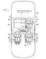
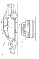
- FIG. 1 is a diagram illustrating an overall configuration of a system using a vehicle seat according to an embodiment. It is the side view (a) of the vehicle in which the alerting
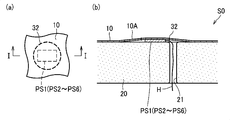
- FIG. 28A is a plan view showing a position display unit according to a first modification
- FIG. 28B is a plan view showing a position display unit according to a first modification
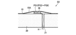
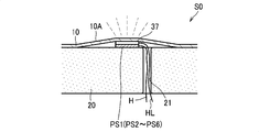
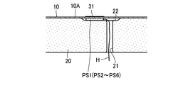
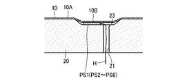
- 27B is a cross-sectional view taken along the line II in FIG. It is sectional drawing which shows the position display part which concerns on a 2nd modification. It is sectional drawing which shows the position display part which concerns on a 3rd modification. It is sectional drawing which shows the position display part which concerns on a 4th modification. It is sectional drawing which shows the position display part which concerns on a 5th modification. It is sectional drawing which shows the position display part which concerns on a 6th modification. It is a flowchart which shows operation
- the vehicle seat S of the present embodiment is an example of a seat, and is configured as a vehicle seat installed in a vehicle CR, for example.
- the vehicle seat S includes a seat body S0 and a control device 100.
- vehicle seats S are provided on four seats of two front seats and two rear seats.
- a control device as an example of a control unit that communicates with a smartphone SP that is an example of a target device 100 is provided.
- the system SYS of the vehicle seat S is configured by the control device 100, the plurality of seat bodies S0, and the smartphone SP.
- the smartphone SP of each seated person P and each seat body S0 are associated in advance by communication via the control device 100.
- the vehicle seat S of this embodiment provides a 100-m running game on the smartphone SP that is the target device.
- the smartphone SP includes a display DSP (see FIG. 4), and the control device 100 operates the character in the game displayed on the display DSP by alternately moving the left and right legs up and down on the seat body S0. Outputs a signal to perform
- the control device 100 is configured to be able to output a notification signal for notifying the notification device other than the smartphone SP that the smartphone SP is being used.
- the vehicle CR includes a door illumination 42 ⁇ / b> A and an electric bulletin board 12 as an example of a notification device.
- the door illumination 42A and the electronic bulletin board 12 are connected to the control device 100 by wire or wirelessly.
- the door illumination 42A is an example of an illumination component and a display device, and includes, for example, a long thin LED (Light Emitting Diode) illumination.
- the door illumination 42 ⁇ / b> A is arranged at the boundary between each side door 41 as an example of a door and the side window 42.
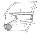
- the door illumination 42 ⁇ / b> A is provided on the upper edge portion of the door trim 21 ⁇ / b> A constituting the interior of the side door 41. That is, the door illumination 42A can be seen from the outside of the vehicle CR and can also be seen from the inside of the vehicle CR.
- the electronic bulletin board 12 is disposed behind the rear seat in the vehicle CR at a position that can be recognized from the outside of the vehicle CR through the rear window 43.
- An electric bulletin board is an example of a display.
- the seat body S0 has a seat cushion S1 and a seat back S2.
- the seat cushion S ⁇ b> 1 and the seat back S ⁇ b> 2 include a cushion pad 20 and a skin 10 that covers the cushion pad 20.
- the cushion pad 20 is made of urethane foam or the like and is supported by a frame (not shown).
- the skin 10 is made of synthetic leather or fabric.
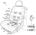
- the seat cushion S1 and the seat back S2 are provided with a plurality of pressure sensors PS1 to PS6 under the skin 10.
- the pressure sensors PS1 to PS6 are sensors that acquire information on the seated person sitting on the seat body S0.
- the pressure sensors PS1 to PS6 are sensors that acquire measurement values for specifying the motion of the seated person P.
- the pressure sensors PS1 to PS6 are arranged so as to be able to detect the state of the seating surface facing the seated person P sitting on the seat body S0, and acquire the pressure value from the seated person P sitting on the seat body S0.
- Each of the pressure sensors PS1 to PS6 is provided in a pair symmetrically with respect to the left and right centers of the vehicle seat S.
- pressure sensors PS1 to PS3 are provided in the seat cushion S1.
- the pressure sensor PS1 and the pressure sensor PS2 are disposed at positions corresponding to the buttocks of the seated person P in the seat cushion S1.
- the pressure sensor PS1 and the pressure sensor PS2 constitute a first cushion sensor SC1 that measures the pressure from the buttocks of the seated person P.
- the pressure sensor PS2 is disposed slightly before the pressure sensor PS1.
- the first cushion sensor SC1 may include only one of the pressure sensor PS1 and the pressure sensor PS2.
- the pressure sensor PS3 is located under the thigh of the seated person P.
- the pressure sensor PS3 constitutes a second cushion sensor SC2 that measures the pressure value from the thigh of the seated person P.
- the pressure sensor PS3 is arranged far away from the pressure sensor PS1 and the pressure sensor PS2.
- the seat back S2 is provided with pressure sensors PS4 to PS6.
- the pressure sensor PS4 is provided at a position corresponding to the back of the waist of the seated person P.
- the pressure sensor PS5 is disposed slightly above the pressure sensor PS4.
- Both of the pressure sensor PS4 and the pressure sensor PS5 constitute a first back sensor SB1 that measures the pressure from the waist of the seated person P.
- the first back sensor SB1 may include only one of the pressure sensor PS4 and the pressure sensor PS5.
- the pressure sensor PS6 is disposed far away from the pressure sensor PS4 and the pressure sensor PS5.
- the pressure sensor PS6 is positioned corresponding to the upper part of the back of the seated person P.
- the pressure sensor PS6 constitutes a second back sensor SB2 that measures the pressure value from the upper part of the back of the seated person P.
- the pressure sensors PS1 to PS6 are elements whose electric resistance changes according to external pressure, for example, and the voltage of the detection signal increases (or decreases) as the pressure value increases.
- the pressure sensors PS1 to PS6 are arranged between the skin 10 and the cushion pad 20.
- the wiring H of each pressure sensor PS1 to PS6 is connected to the control device 100 (see FIG. 4) through a hole 21 formed in the cushion pad 20.
- a paint 31 as an example of a position display unit is applied to positions corresponding to the pressure sensors PS1 to PS6 on the outer surface 10A of the skin 10.
- the coating material 31 is exposed to the outside of the skin 10 by being applied to the outer surface 10 ⁇ / b> A of the skin 10.
- the color of the paint 31 is different from that of the outer surface 10 ⁇ / b> A of the skin 10.
- the color of the paint 31 can be a conspicuous color with respect to black, such as yellow.
- such a paint 31 displays the positions of the pressure sensors PS1 to PS6 so as to be visible from the outside of the seat body S0 before the seated person sits on the vehicle seat S.
- the pressure values acquired by the pressure sensors PS1 to PS6 are P1 to P6, respectively, and the right and left pressure values are appended with R and L, such as P1 R and P1 L , respectively. Indicated by letters.
- the pressure sensors PS1 to PS6 are, for example, elements whose electrical resistance changes due to external pressure, and the voltage of the detection signal increases (or decreases) as the pressure value increases. For this reason, the magnitude of the pressure value is actually compared based on the magnitude of the voltage value, but in this specification, for the sake of easy understanding, description will be made in the form of determining by the magnitude of the pressure value.
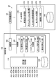
- the control device 100 includes a measurement value acquisition unit 110, a processing unit 120, a communication unit 130, and a storage unit 190.
- the smartphone SP includes a game processing unit 210 and a storage unit 290.
- the control device 100 and the smartphone SP have a CPU, a ROM, a RAM, a rewritable nonvolatile memory, and the like (not shown), and each functional unit is realized by executing a program stored in advance.
- the control device 100 can communicate with the smartphone SP via the communication unit 130 and the short-range communication device 3A, and provides the smartphone SP with a predetermined screen and sound in cooperation with an application installed on the smartphone SP. Data input by the SP can be acquired.
- short-range wireless communication such as Bluetooth (registered trademark) or Wi-Fi (registered trademark).
- the control device 100 can communicate with the smartphone SP via the communication unit 130 and the short-range communication device 3A, and provides the smartphone SP with a predetermined screen and sound in cooperation with an application installed on the smartphone SP. Data input by the SP can be acquired.
- the measurement value acquisition unit 110 has a function of acquiring a pressure measurement value from each of the pressure sensors PS1 to PS6 every fixed control cycle.
- the measurement value acquired by the measurement value acquisition unit 110 is stored in the storage unit 190 and used by the processing unit 120.
- the storage unit 190 is used to appropriately store data necessary for calculation, processing, and the like.
- the processing unit 120 communicates with the smartphone SP and executes a process of transmitting an operation signal for operating the 100 m running game application provided by the smartphone SP.
- the processing unit 120 has a function of notifying the outside through the door illumination 42 ⁇ / b> A and the electronic bulletin board 12 that an application running 100 m is being used on the smartphone SP.
- the processing unit 120 includes a Yes signal output unit 121, a No signal output unit 122, a calibration processing unit 124, a step signal output unit 125, and a notification signal output unit 126.
- the processing unit 120 has a first operation mode for outputting an operation signal based on measured values of the pressure sensors PS1 to PS6, and a second operation mode for not outputting an operation signal. And it can operate
- the Yes signal output unit 121 and the No signal output unit 122 output a Yes signal or a No signal to the smartphone SP according to the operation of the seated person P after the processing unit 120 receives the participation acceptance signal from the smartphone SP.
- the Yes signal output unit 121 outputs a Yes signal on condition that the pressure value P6 R obtained from the right pressure sensor PS6 (first pressure sensor) exceeds a predetermined threshold value P6th.
- the No signal output unit 122 outputs a No signal on condition that the pressure value P6 L obtained from the left pressure sensor PS6 (second pressure sensor) exceeds a predetermined threshold value P6th.
- the first operation for starting the game of the smartphone SP is assigned to the Yes signal
- the second operation for selecting not to perform the game is assigned to the No signal.
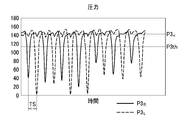
- the calibration processing unit 124 acquires the pressure values P3 R and P3 L of the left and right pressure sensors PS3 after the processing unit 120 receives the calibration start signal from the smartphone SP. Then, a normal pressure P3 n that is an average pressure of the seated person P sitting at that time and a threshold value P3th for detecting a peak of the pressure value are determined, and an average leg of the seated person P is determined. to calculate the normal step cycle TS n is the period to move the output to the smartphone the SP.
- the pressure values P3 R and P3 L change, for example, as shown in FIG. In FIG. 7, the portion where the pressure is suddenly reduced indicates that the pressure of the portion of the pressure sensor PS3 is reduced due to the seated person P raising his leg. That is, the pressure value near 140 where the pressure is not reduced becomes an average normal pressure P3 n when the legs are not raised.
- the normal pressure P3 n for example, the difference between the previous value and the current value of the pressure values P3 R and P3 L (the value obtained by subtracting the previous value P3 (n ⁇ 1) from the current value P3 (n)).
- Is equal to or less than a predetermined value that is, when the change in value is small
- the current values may be aggregated and averaged.
- the threshold value P3th is a threshold value for determining that the leg is being raised. For example, in the case of FIG. 7, a value of about 100 to 120 may be used. Therefore, the threshold P3th may use a value obtained by multiplying a predetermined value to the normal pressure P3 n. For example, a value obtained by multiplying the normal pressure P3 n by a predetermined value of about 0.6 to 0.9 can be set as the threshold value P3th.
- the normal step period TS n is an average value of the step period TS which is a time interval between the peaks of the pressure values P3 R and P3 L.
- the pressure values P3 R and P3 L are such that the difference between the previous value and the current value is negative to positive under the condition that the pressure values P3 R and P3 L are smaller than the threshold value P3th (exceeding from the upper side to the lower side). It can be determined that the peak has been reached when the value changes to, and the previous value P3 (n-1) at this time can be set as the peak value Pm.
- the step signal output unit 125 detects the peaks of the pressure values P3 R and P3 L according to the movement of the seated person P, and calculates the peak value Pm. . Peak detection and peak value Pm calculation can be performed in the same manner as the calibration processing unit 124. Then, the step strength F (F R , F L ), which is the size of raising the leg, is calculated.
- the step intensity F can be a peak size, that is, a value obtained by subtracting the peak value Pm from the normal pressure P3. In this embodiment, in order to eliminate the difference due to the size of the seated person P, the value is normalized by the normal pressure P3 n .
- the step signal output unit 125 detects the peaks of the pressure values P3 R and P3 L
- the step signal output unit 125 outputs the peak value Pm and the step intensity F to the smartphone SP.
- the step signal output unit 125 outputs a signal based on the change in the pressure value P3 obtained from the pressure sensor PS3.
- the notification signal output unit 126 outputs a notification signal for notifying that the smartphone SP is in use to the door illumination 42 ⁇ / b> A and the electric bulletin board 12 that are notification devices when the communication with the smartphone SP is possible. Configured to do.
- the notification signal output unit 126 outputs a notification signal from the reception of the race start signal from the smartphone SP until the reception of the race end signal.
- the notification signal output unit 126 may output a notification signal to all the door lights 42A when at least one vehicle seat S satisfies the condition, or one vehicle seat S satisfies the condition.
- the notification signal may be output only to the door illumination 42A of the side door 41 corresponding to the vehicle seat S.
- a notification signal is output to the electronic bulletin board 12 when at least one vehicle seat S satisfies the condition.
- the door illumination 42A is configured to light up or blink when it receives a notification signal.
- the electronic bulletin board 12 receives the notification signal, as shown in FIG. 2 (b), the electronic bulletin board 12 displays that the 100m running application is being used by characters, such as “100m running play!”.
- the game processing unit 210 of the smartphone SP executes a game progress process when the application is launched.
- the game processing unit 210 includes a participation reception processing unit 211, a calibration instruction unit 212, a character movement processing unit 213, an onomatopoeia determination unit 214, and a result output unit 219.
- the game processing unit 210 stores the signal received from the control device 100 in the storage unit 290 together with the reception time.
- the storage unit 290 is used for appropriately storing data necessary for calculation, processing, and the like.
- the game processing unit 210 appropriately transmits data such as the calculated travel distance L and the result of the exercise to the control device 100 so as to share the data with the smartphone SP corresponding to the other vehicle seat S. It is configured.
- the control device 100 accumulates these data in the storage unit 190.
- the participation acceptance processing unit 211 displays a start screen for accepting participation on the display DSP, transmits a participation acceptance signal to the control device 100, and accepts a Yes signal or a No signal from the control device 100 for a predetermined time.
- the start screen is, for example, a screen as shown in FIG. 16, and a message “Do you want to participate? Please press the seat with your shoulders” and “No left shoulder right shoulder Yes” as a notification prompting the seated person P to move.
- the display is output to the display DSP.
- the display of Yes and No may give the function of the button which can touch the display DSP and can input Yes signal or No signal to smart phone SP, respectively.
- the participation reception processing unit 211 performs a process of proceeding to the game progress process when the Yes signal is received, and terminates the application without proceeding to the game progress process when the No signal is received.
- the game processing unit 210 receives neither the Yes signal nor the No signal and the predetermined time has elapsed, the game processing unit 210 transmits an acceptance end signal to the control device 100 to end the application.
- the calibration instruction unit 212 displays a calibration screen, transmits a calibration start signal to the control device 100, and receives a calibration-related signal from the control device 100 for a predetermined time. When the predetermined time has elapsed, the calibration instruction unit 212 outputs a calibration end signal to the control device 100.
- the character movement processing unit 213 When the character movement processing unit 213 receives the step strength F during the race of 100 m running, the character movement processing unit 213 moves the character on the display DSP toward the goal. The amount of movement at this time depends on the magnitude of the step strength F. For example, the character movement processing unit 213 moves the character toward the goal by F [m].
- the onomatopoeia determination unit 214 determines an onomatopoeia (a mimetic word such as “Tobachiichi”) that expresses how the seated person P is running during a 100-m race, and outputs the onomatopoeia on the display DSP.
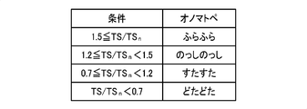
- the determination of onomatopoeia can be made, for example, by comparing the step period TS, which is the period in which the seated person P moves the leg, with the determination condition shown in FIG.
- the step period TS is a period of the step strength F received from the control device 100, but since the interval at which the step strength F is received is not constant, for example, it can be calculated with an average period of the past 20 m. it can.
- determining a representation of onomatopoeia by comparing the value obtained by dividing the step period TS in the normal step cycle TS n and threshold. For example, when the TS / TS n is long periods at 1.5 or more, and a "dizzy", 1.2 or more, in the case of less than 1.5 "Nosshinosshi", 0.7 or more to less than 1.2 In the case of, it is determined to be “sutasuta”, and in the case of less than 0.7, it is determined to be “smooth”.
- the result output unit 219 determines the exercise result and advice and outputs the result on the display DSP after the seated person P has scored in the 100 m running game.
- the result of the exercise is transmitted to the control device 100.
- the result output unit 219 determines the exercise level, the exercise amount, the exercise intensity, and the advice as the exercise result.
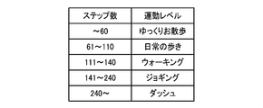
- the exercise level is determined with reference to the exercise level determination table of FIG. 9 based on the number of steps while running 100 m. For example, in the exercise level determination table, when the number of steps is 60 or less, “slow walk”, 61-110, “daily walk”, 111-140, “walking”, 141-240, For “jogging” and 240 or more, “dash” is set.
- the amount of exercise can be obtained, for example, by the cumulative value of the step strength F while running 100 m.
- the exercise intensity is indicated by METs (Metabolic (equivalents).
- the value of the exercise intensity can be determined by, for example, multiplying the number of steps while running 100 m by a predetermined coefficient.
- Advice can be determined with reference to an advice table stored in the storage unit 290 in advance.
- the advice table for example, parameters such as the number of steps, a goal time of 100 m, an average step period, and the like are associated with predetermined advice. Then, after the goal of 100 m running, advice can be searched from these parameters and determined.
- the result output unit 219 determines the exercise level, the exercise amount, the exercise intensity, and the advice, and then displays these results on the display DSP.
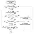
- the processing unit 120 first executes steps S11 to S17 related to game participation. Specifically, first, it is determined whether or not a participation acceptance signal has been received (S11). When the participation acceptance signal is received (S11, Yes), the processing unit 120 acquires the pressure values P6 R and P6 L (S12), and determines whether the right pressure value P6 R is larger than the threshold value P6th (S13). ). When P6 R is larger than P6th (S13, Yes), a Yes signal is transmitted (S14), and the process related to game participation is terminated.
- P6 If R is not greater than P6th (S13, No), the processing unit 120, the left pressure value P6 L determines whether P6th greater (S15). When P6 L is larger than P6th (S15, Yes), a No signal is transmitted (S16), and the process related to game participation is terminated.
- the processing unit 120 determines whether or not an acceptance end signal has been received (S17), and when not received (S17, No), the processing from step S12 If the process is repeated and received (S17, Yes), the process related to game participation is terminated.
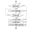
- the calibration processing unit 124 of the processing unit 120 executes steps S21 to S26 related to the calibration process as shown in FIG.
- the processing unit 120 determines whether or not a calibration start signal has been received (S21), and if received (S21, Yes), acquires and stores the pressure values P3 R and P3 L (S22). Then, it is determined whether or not a calibration end signal has been received, and steps S22 to S23 are repeated until the calibration end signal is received (S23, No), and if received (S23, Yes), the process proceeds to step S24.
- step S24 the calibration processing unit 124 calculates a normal pressure P3 n based on the pressure values P3 R and P3 L acquired and stored for a predetermined period. Then, to set the threshold P3th from normal pressure P3 n (S25). Moreover, to calculate the normal step cycle TS n, and transmits to the smartphone SP (S26). In step S21, when the calibration start signal is not received (No), the calibration processing unit 124 proceeds to step S30 (see FIG. 12) without performing the calibration process.
- the processing unit 120 performs processing related to the race in steps S30 to S40. As shown in FIG. 12, first, the processing unit 120 determines whether or not a race start signal has been received from the smartphone SP (S30). When the race start signal has not been received (S30, No), the processing unit 120 ends the process. When the race start signal is received (S30, Yes), the notification signal output unit 126 starts outputting the notification signal (S51). Next, the step signal output unit 125 acquires and stores the pressure values P3 R and P3 L (S31).
- step signal output unit 125 calculates the step strength F R from the normal pressure P3 n and the pressure value P3 R (S34). Then, it transmits the calculated step strength F R smartphone SP (S35).
- the step signal output unit 125 Step strength F R The process proceeds to step S36 without calculating and transmitting.
- step S36 ⁇ S39 step signal output unit 125 performs the left pressure value P3 L, calculation of the detection steps strength F L of the peak, the process of transmission. Since these processes are the same as steps S31 to S35, description thereof will be omitted.
- step S40 the processing unit 120 determines whether or not a race end signal has been received. If not received (S40, No), the processing from step S31 is repeated and received (S40, Yes). After the signal output unit 126 finishes outputting the notification signal (S52), the process is finished.
- the smartphone SP starts application processing, and displays a start screen on the display DSP as shown in FIG. 13 (S110).
- the start screen is, for example, a screen as shown in FIG.
- an explanation indicating that the left shoulder is “No” and the right shoulder is “Yes” is displayed together with the letters “Do you want to participate? Please press the sheet with your shoulder”. Also, the remaining time for participation can be displayed.
- the participation reception process part 211 transmits a participation reception signal to the control apparatus 100 (S111).
- the participation reception processing unit 211 determines whether or not a Yes signal has been received (S112), and if received (S112, Yes), transmits a reception end signal to the control device 100 (S118), and a game progress process (S200). After that, the process ends.
- the game progress process will be described later.
- the participation reception processing unit 211 determines whether or not the No signal has been received when the Yes signal has not been received (S112, No), and ends the process when received (S113, Yes). On the other hand, when the No signal is not received (S113, No), a count indicating the remaining time is displayed (S114), and it is determined whether the count is 0 (S115). When the count is not 0 (S115, No), the participation acceptance from Step S112 is continued, and when the count is 0 (S115, Yes), an acceptance end signal is transmitted to the control device 100 (S116). The process is terminated.
- the calibration instruction unit 212 displays a calibration screen on the display DSP (S211).
- the calibration screen displays, for example, an instruction with characters “warming up, please raise the legs alternately while sitting” and the remaining time for calibration as shown in FIG.
- an animation in which a character CH1 such as a seat is running is displayed on the display DSP, it is easy to understand what the seated person P should do.
- indication part 212 transmits a calibration start signal to the control apparatus 100 (S212). Then, the remaining time count is updated and displayed on the display DSP (S213), and it is determined whether the count has reached 0 (S214). When the count is not 0 (S214, No), the countdown display in step S213 is continued. When the count is 0 (S214, Yes), a calibration end signal is transmitted to the control device 100 (S215). ).
- the game processing unit 210 displays a race start screen as shown in FIG. 15 (S220).
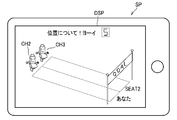
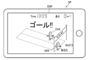
- the race start screen is, for example, a screen as shown in FIG. 18, and displays characters “About position! Yoi” and a countdown number until the start.
- the race screen also displays a 100 m competitive lane and seat characters CH2 and CH3 in each lane. For example, when a plurality of lanes are displayed, and there are other seated persons P who participate at the same time, the characters “you” indicating the player and the characters “SEAT2” indicating that they are participants of other seats are displayed. Displayed in the lane.
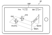
- the game processing unit 210 transmits a race start signal to the control device 100 (S221). Then, the character movement processing unit 213, Step strength F R, determines whether it has received the F L (S222). When receiving (S222, Yes), the character movement processing section 213 performs processing of moving the character CH2 according to the magnitude of the steps strength F R, F L (S223) . Then, the travel distance L is updated, and the travel distance L is transmitted to the control device 100. Further, the character movement processing unit 213 displays the remaining distance on the display DSP (S224).
- onomatopoeia determination unit 214 determines a onomatopoeias be displayed from step period TS and the normal step cycle TS n, on a display DSP (S225).
- a display DSP DSP
- the game processing unit 210 also displays the time from the start.
- Character movement processing unit 213 proceeds to Step strength F R, if not received F L (S222, No), step S226 without executing the steps S223 ⁇ S225.
- the game processing unit 210 acquires the travel distance L of the character CH3 of the seated person P of the other seat from the control device 100, and moves the character CH3 of the other seat as necessary (S226).
- the character movement processing unit 213 determines whether or not the travel distance L is 100 or more (S227), and if it is less than 100, repeats the race processing from step S222. On the other hand, when the travel distance L becomes 100 or more (S227, Yes), a race end signal is transmitted to the control device 100 (S228). At the end of the race, for example, a screen as shown in FIG. 20 is displayed. On this screen, the remaining distance is 0 m, and the time at the goal is displayed.
- the result output unit 219 determines the exercise level, the exercise amount, the exercise intensity, and the advice as a result of the exercise, and outputs them on the display DSP (S229).
- the result screen is, for example, a screen as shown in FIG. In the result screen, it is preferable to display the ranking among the competitors so far from the data accumulated in the control device 100 so far.
- a happy face character CH5 is displayed.
- a character with a disappointing face is displayed.
- the result output unit 219 displays the result of the exercise, the application process ends.
- the seated person P can view the position of the paint 31 applied to the seat body S0 before sitting on the seat body S0, the position of each pressure sensor PS1 to PS6 can be easily confirmed. As a result, the seated person P can appropriately set his / her left and right thighs on the left / right pressure sensors PS3, and thus can enjoy the game by effectively using each pressure sensor PS3.
- the position display part is compared with a case where a position display part (spacer 36: see FIG. 31) hidden by the skin 10 as described later is employed. 31) can be easily recognized.
- the position display part (paint 31) can be more easily recognized.
- control device 100 Since the control device 100 outputs the pressure values acquired from the pressure sensors PS1 to PS6 to the smartphone SP as an operation signal for operating the game application of the smartphone SP, the seated person P sitting on the vehicle seat S
- the smartphone SP can be operated by moving a leg or shoulder on the seat body S0.
- the smartphone SP can be operated by moving the body on the seat body S0. For this reason, when the user gets tired in the vehicle, the body can be appropriately moved and refreshed.
- the electric bulletin board 12 displays that the 100 m running application is being used. For this reason, it is possible to notify the outside of the vehicle CR that other people are using the 100 m running application. That is, the seated person P can share with the person outside the vehicle CR that the 100 m application is being used. In particular, according to the electronic bulletin board 12, it is possible to display the fact that the 100 m running application is being used to the outside in an easy-to-understand manner.
- the pressure sensors PS1 to PS6 can detect the state of the seating surfaces S21 and S22 facing the seated person P, the seated person P can easily access the pressure sensors PS1 to PS6. That is, since the seated person can operate the target device by changing the state of the seating surface, it is easy to operate the smartphone SP.
- the Yes signal and the No signal are output on condition that the pressure value P6 exceeds the threshold value P6th, and the step strength F is also determined on the condition that the pressure value P3 exceeds the threshold value P3th from the top to the bottom. Therefore, the smartphone SP can be prevented from being erroneously operated against the intention of the seated person P.
- the present invention is applied to the operation of a 100-m run game as an example of the game, but can be applied to the operation of other games.
- the target device to be operated is not limited to a smartphone, but may be a personal computer, a tablet PC, a navigation system, or the like.
- the display is not limited to a device, and may be a telephone, audio, or the like.
- the target device does not include the vehicle itself (targeting the driving operation of the vehicle). However, as long as the operation is other than driving the vehicle, the target device may be fixedly provided on the vehicle, and the operation may be an operation of moving the air conditioner or the window glass up and down.
- the notification signal is output between the time when the race start signal is received and the time when the race end signal is received.
- the notification signal may be output during other periods.
- a notification signal may be output while a predetermined application of the smartphone SP is launched and communication with the control device 100 is possible.
- the notification device is arranged inside the vehicle, but the notification device may be provided on the outer surface of the vehicle.
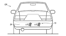
- the rear bumper 24 may be provided with a lighting component 13 that shines in a shape representing a running person as a notification device.
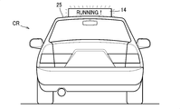
- the notification device may be an indicator lamp 14 installed on the roof 25 of the vehicle CR. For example, characters “RUNNING!” Are displayed on the indicator lamp 14. By lighting or blinking such a lighting component 13, it is possible to effectively notify that the target device is being used outside the vehicle CR. In particular, when the indicator lamp 14 is used, it can be easily displayed outside that the target device is being used.
- reporting apparatus etc. may be the illumination components etc. which were provided in sheet
- the notification device inside the vehicle CR such as the seat body S0
- the passenger can be notified of the use of the target device.
- the lighting component inside the vehicle CR is arranged at a position that can be recognized from the outside of the vehicle CR, it is possible to notify the person outside the vehicle CR of the use of the target device.
- the notification device may be an information sharing server that is connected to a plurality of users' terminals via a network and transmits the received information to the plurality of terminals in order to share the information.
- the system SYS2 includes a vehicle seat S having the same function as that of the embodiment and an information sharing server 60.
- the vehicle seat S and the information sharing server 60 are communicably connected via the Internet N as an example of a network.
- the control device 100 for the vehicle seat S is configured to be able to acquire position information from the smartphone SP.
- the control device 100 is configured to output the notification signal including the position information when outputting the notification signal to the information sharing server 60.
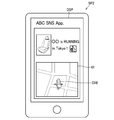
- the information sharing server 60 is configured such that a plurality of other smartphones SP2 in which a dedicated SNS (Social Networking Service) application is installed can be connected. Then, the information sharing server 60 transmits information transmitted from the smartphone SP in response to a request from the SNS application or when a predetermined condition is satisfied (in particular, notification information including position information here). By transmitting to SP2, information can be shared among a plurality of users.
- SNS Social Networking Service
- the application of the smartphone SP2 displays the map 61 on the display DSP, and the position corresponding to the position information included in the received notification information on the map 61. Then, a process of displaying the sheet character CH6 is executed. Furthermore, the city name is determined from the location information, and a process of displaying information indicating that the target device is in use on the display DSP, such as “XXis RUNNING in Tokyo (city name)”, is executed. To do. In order to determine the city name from the position information, a database storing the relationship between the range of the position information and the city name is stored in advance in the information sharing server 60, and the city name is searched from the position information.
- the displayed map may be a map displayed on the navigation system instead of the smartphone SP2.
- the position information is not limited to being acquired from the smartphone SP.
- the seat body S0 may include a GPS (Global Positioning System) that acquires position information.
- seats are not limited to those installed on vehicles.
- it can be applied to seats of stadiums and arenas. An example of this form will be described with reference to FIG.
- the sheet S10 includes a plurality of pressure sensors PS, a control unit 100A, a speaker SPK as an example of a target device, and a lighting member 18 as an example of a notification device in the sheet body S0.
- a control unit 100A for example, two pressure sensors PS are provided side by side on the seat back and two side by side on the seat cushion.
- the pressure sensor PS is connected to the control unit 100A.
- the control unit 100A acquires the pressure value from each pressure sensor PS, and uses the tone color corresponding to the position of each pressure sensor PS (for example, the type of instrument such as a trumpet or a drum) to obtain the pressure value acquired from the pressure sensor PS. A process of producing a sound from the speaker SPK with a sound having a volume corresponding to the loudness is executed.
- the control unit 100A is configured to output power (signal) that causes the illumination member 18 to emit light, at the same time as performing the process of producing sound from the speaker SPK. That is, the control unit 100A outputs a notification signal to the illumination member 18 that is a notification device when the control unit 100A can communicate with the speaker that is the target device. It is desirable that the electric power for emitting light from the illumination member 18 has a magnitude corresponding to the magnitude of the pressure value acquired from the pressure sensor PS.
- the seat S10 having such a configuration, for example, when a baseball game is being held in a stadium, a seated person sitting on the seat S10 applies pressure to the pressure sensor PS of the seat S10, thereby causing the speaker SPK to You can cheer with a sound.
- the lighting member 18 indicates that the speaker SPK of the sheet S10 is in use, and other spectators feel that they are going to try it. be able to. For this reason, the support which made the sound can be gradually expanded in the stadium, and the support can be performed enormously.
- the paint 31 is used as a form for indicating the position of the sensor.
- the means for indicating the position of the sensor is not limited to the paint. Another mode for indicating the position of the sensor will be described next.
- the thread member 32 sewn into the skin 10 is exemplified as the position display section.
- the thread member 32 may be, for example, a thread made of fibers such as cotton, wool, silk, nylon, or a string made of leather.
- a part of the thread member 32 is exposed to the outside of the skin 10 as a pattern by being sewn into the skin 10.
- the pattern formed by the thread member 32 is arranged at a position corresponding to each pressure sensor PS1 to PS6.
- the pattern may be any pattern. For example, as shown in FIG. 27A, a circular pattern surrounding the pressure sensor PS1 may be employed.
- the color of the thread member 32 is different from the color of the skin 10. Even if it is the 1st modification comprised as mentioned above, the effect similar to the said embodiment can be acquired.
- the hook-and-loop fastener 33 is illustrated as a position display part.
- the surface fastener 33 includes a first member 33A provided on the skin 10 and a second member 33B that can be attached to and detached from the first member 33A.
- the first member 33A is arranged at a position corresponding to each pressure sensor PS1 to PS6 in the skin 10.
- the first member 33A may be formed integrally with the skin 10 or may be fixed to the skin 10 with an adhesive or the like.
- the first member 33A has a hook portion raised in a hook shape.
- the second member 33B has a loop portion raised in a loop shape.
- the loop portion of the second member 33B can be engaged / disengaged with respect to the hook portion of the first member 33A.
- the hook portion may be provided on the second member 33B and the loop portion may be provided on the first member 33A. In this case, since the clothes of the seated person are not caught by the loop portion of the first member 33A in a state where the second member 33B is removed, it is preferable.
- the first member 33A is exposed to the outside of the skin 10 in a state where the second member 33B is removed.
- the second member 33B is exposed to the outside of the skin 10 in a state where it is attached to the first member 33A.
- the color of the surface exposed to the outside of the second member 33B is different from that of the skin 10.
- the color of the first member 33A may be any color, but may be the same color as the skin 10, for example, the same color.
- the position of each of the pressure sensors PS1 to PS6 is different from that of the skin 10 by attaching the second member 33B to the first member 33A.
- the second member 33B can be made conspicuous.
- the appearance of the seat body S0 can be improved by removing the second member 33B.
- the remaining effects of this modification are similar to those of the aforementioned embodiment.
- a snap button including a convex metal fitting and a concave metal fitting can be cited.
- a display skin 34 different from the skin 10 that occupies most of the exterior of the sheet main body S0 is exemplified as the position display unit.
- display skins 34 are integrally sewn at positions corresponding to the pressure sensors PS1 to PS6 in the skin 10.
- the display skin 34 is made of a material different from that of the skin 10 or a different color.
- the display skin 34 is exposed outside the skin 10. Even in the third modified example configured as described above, it is possible to obtain the same effect as that of the above embodiment.
- a push button type switch 35 as a sensor and a position display unit.
- holes 11 are formed in the skin 10 at positions corresponding to the pressure sensors PS1 to PS6.
- surroundings of the hole 11 are folded inward and put together by sewing.
- the switch 35 includes a base 35A and a push button 35B.
- a substrate constituting a switch function is accommodated in the base 35A.
- the wiring H connected to the substrate or the like is connected to the control device 100 through the hole 21 of the cushion pad 20 as in the above embodiment.
- the base 35A is disposed between the skin 10 and the cushion pad 20.
- the push button 35 ⁇ / b> B is exposed to the outside by protruding outward from the skin 10 through the hole 11 from the base 35 ⁇ / b> A.
- the color of the push button 35 ⁇ / b> B is a color different from that of the skin 10.
- the pressure sensor PS1 may be exposed from the hole 11 to the outside. Further, another member provided on the pressure sensor PS1 may be exposed from the hole 11. Moreover, when using a sensor as a position display part like this modified example, this sensor is good also as a position display part by sticking a sensor on the outer surface of a skin, for example.
- the spacer 36 disposed between the skin 10 and the pressure sensor PS1 is exemplified as the position display unit.
- the spacer 36 is made of, for example, resin, and a part of the skin 10 is protruded from a part around the part.
- the protruding amount of a part of the epidermis 10 is a somewhat large protruding amount so that a seated person can visually recognize the protruding amount. Even in this form, the same effect as in the above embodiment can be obtained.
- a planar light-emitting body 37 as an example of a light-emitting member is illustrated as a position display unit.
- the planar light-emitting body 37 is a member that emits light to the outside of the skin 10 and emits light when energized.
- the planar light emitter 37 is disposed between the skin 10 and the pressure sensor PS1.
- the wiring HL of the planar light emitter 37 is connected to the control device 100 through the hole 21 of the cushion pad 20.
- the skin 10 is made of a material that can transmit light from the planar light-emitting body 37, for example, a mesh-like material. Note that a small hole may be provided in the skin 10 and light from the planar light-emitting body 37 may be emitted to the outside through this hole.
- control device 100 executes the control shown in FIG.
- the control device 100 constantly executes the control shown in FIG.
- control device 100 first determines whether or not communication with the smartphone SP is possible (S311). If it is determined in step S311 that communication is not possible (No), the control device 100 ends this control.
- step S311 When it is determined in step S311 that communication is possible (Yes), the control device 100 performs energization to the planar light emitter 37 to cause the planar light emitter 37 to emit light (S312). After step S312, the control device 100 determines whether or not the seated person is seated on the seat body S0 based on information from the pressure sensors PS1 to PS6 (S313).
- step S313 If it is determined in step S313 that the user is not seated (No), the control device 100 ends this control. When it is determined that the user is seated in step S313 (Yes), the control device 100 stops energizing the planar light emitter 37, turns off the planar light emitter 37 (S314), and ends this control. To do.
- the control device 100 can communicate with the smartphone SP, that is, when the occupant uses the pressure sensors PS1 to PS6, the planar light emitter 37 emits light, so that the planar light emitter 37 shines unnecessarily when not in use. Can be suppressed. Since the planar light-emitting body 37 does not shine when not in use, the appearance of the sheet body S0 can be improved.
- planar light-emitting body 37 Since the planar light-emitting body 37 is turned off after the seated person sits on the seat body S0, for example, power consumption can be suppressed as compared with a mode in which the planar light-emitting body 37 continues to emit light after sitting.
- the light-emitting member is not limited to the planar light-emitting body 37, and may be, for example, an LED. In the case of a non-planar light emitting member such as an LED, it may be embedded in a cushion pad around the sensor. Moreover, you may affix a planar light-emitting body on the outer surface of an outer_skin
- the portion where the pressure sensors PS1 to PS6 are provided in the outer skin 10 is configured to protrude outward, but the present invention is not limited to this.
- the cushion pad 20 may be provided with a recess 22 having a depth corresponding to the thickness of the pressure sensors PS1 to PS6, and the outer surface 10A of the skin 10 may be made flat. Even in this case, the same effect as in the above embodiment can be obtained by providing a position display section such as the paint 31 at positions corresponding to the pressure sensors PS1 to PS6 in the skin 10.
- the cushion pad 20 is provided with a recess 23 having a depth larger than the thickness of the pressure sensors PS1 to PS6, and corresponds to the pressure sensors PS1 to PS6 in the skin 10. You may dent the done part. That is, in this modification, the outer surface 10A of the skin 10 is formed with a recess 10B disposed at a position corresponding to the pressure sensors PS1 to PS6. In this modification, since the recess 10B functions as a position display unit, the same effect as in the above embodiment can be obtained.
- the present invention can also be implemented in other forms as follows.
- the position display unit that displays the position of the sensor from the outside of the seat main body is provided.
- the position display There may be no part. That is, the position of the sensor may not be visible from the outside of the seat body.
- the pressure sensor is exemplified as the sensor, but the sensor may be another type of sensor, for example, a capacitance sensor. Moreover, when measuring a pressure, a pressure distribution sensor can also be employ
- the seated person information is not limited to information for specifying the seated person's movement, and may be, for example, the blood pressure of the seated person.
- control device 100 and a part of the smartphone SP constitute the control unit as a whole, but only the control device 100 may constitute the control unit, or only the smartphone constitutes the control unit. May be. Moreover, it communicates with the computer provided in another place like what is called a cloud computer, and the said cloud computer can also comprise a part or all of a control part.
- the target device is not limited to the smartphone SP, and may be a tablet terminal, for example. Further, the operation signal for operating the target device may be power itself for driving a motor or the like.
- control device and the smartphone are connected by wireless communication, but may be connected by wired communication.
- the operation for operating the target device only the operation of raising and lowering the leg and pressing the shoulder against the seat back is exemplified, but the operation of twisting the upper body, the operation of swinging back and forth, left and right or turning
- the target device may be configured to be operated by other operations such as an operation of shaking the buttocks.
- the seat mounted on the vehicle of the automobile is exemplified as the vehicle seat.
- the vehicle seat may be a seat of a vehicle such as a railway other than the automobile, or a ship other than the vehicle, an aircraft It may be a sheet such as a rocket.
- the seat may be a seat other than a vehicle, for example, a seat chair or a chair used in a room such as a house.
Landscapes
- Engineering & Computer Science (AREA)
- Mechanical Engineering (AREA)
- Aviation & Aerospace Engineering (AREA)
- Transportation (AREA)
- Physics & Mathematics (AREA)
- General Physics & Mathematics (AREA)
- Seats For Vehicles (AREA)
- Chair Legs, Seat Parts, And Backrests (AREA)
- Measurement Of The Respiration, Hearing Ability, Form, And Blood Characteristics Of Living Organisms (AREA)
Abstract
【課題】シート(S)は、シート本体(S0)と、シート本体(S0)に設けられ、シート本体(S0)に座っている着座者の情報を取得するセンサ(PS1~PS6)と、を備える。シート(S)は、シート本体(S0)の外側からセンサの位置を視認可能に表示する位置表示部としての塗料(31)を備える。
Description
本発明は、シート本体に座っている着座者の情報を取得するセンサを備えるシートに関する。
従来、運転者のシートに圧力センサ等を搭載して、着座者の着座姿勢を推定する装置が知られている(特許文献1)。
ところで、従来の装置は、運転者の着座姿勢を評価して提示するだけであるので、あまり有効に利用できないという問題がある。有効に利用する例として、例えば、正しい着座姿勢を運転者に提示し、運転者の現在の着座姿勢が正しい着座姿勢となるように運転者に動作を促すことが考えられる。しかしながら、この場合、運転者がセンサの位置を知らないと、自分の身体をどのように動かしてよいか分からないという問題が生じる。
そこで、本発明は、着座者が容易にセンサの位置を知ることができ、適切にセンサを利用することができるシートを提供することを目的とする。
また、本発明は、シートの新たな価値を提案するべく、シート上の動作により対象機器を操作することができるとともに、この機能を使用中であることを他の人に知らせることが可能なシートを提供することを目的とする。
前記した課題を解決する本発明は、シート本体と、シート本体に設けられ、シート本体に座っている着座者の情報を取得するセンサと、を備えるシートである。
シートは、シート本体の外側からセンサの位置を視認可能に表示する位置表示部を備える。
シートは、シート本体の外側からセンサの位置を視認可能に表示する位置表示部を備える。
この構成によれば、位置表示部によってシート本体の外側からセンサの位置を視認することができるので、着座者が容易にセンサの位置を知ることができ、適切にセンサを利用することができる
また、シート本体は、クッションパッドと、クッションパッドを被覆する表皮とを備え、センサは、クッションパッドと表皮との間に配置されていてもよい。
また、位置表示部は、表皮の外側に露出していてもよい。
これによれば、位置表示部が表皮の外側に露出するので、位置表示部を視認しやすくすることができる。
また、位置表示部の色は、表皮の色と異なっていてもよい。
これによれば、位置表示部の色が表皮と異なるので、位置表示部を視認しやすくすることができる。
また、表皮は、センサに対応した位置に孔を有し、位置表示部は、孔を通して表皮の外側に露出していてもよい。
これによれば、位置表示部が孔を通して表皮の外側に露出するので、位置表示部を視認しやすくすることができる。
また、位置表示部は、表皮とセンサとの間に配置され、表皮の一部を当該一部の周囲の部分よりも突出させてもよい。
これによれば、表皮の一部が周囲の部分よりも突出することで、着座者が容易にセンサの位置を知ることができる。
また、位置表示部は、表皮の外側に光を出射する発光部材であってもよい。
これによれば、光によって着座者が容易にセンサの位置を知ることができる。
また、シートは、センサから情報を取得可能にセンサと接続されるとともに、シート本体外の対象機器と通信可能に接続される制御部をさらに備えていてもよい。
また、位置表示部は、表皮の外側に光を出射する発光部材であり、制御部は、対象機器と通信可能になった場合に、発光部材を発光させてもよい。
これによれば、制御部が対象機器と通信可能な場合、つまり着座者がセンサを使用する場合に、発光部材が発光するので、非使用時に発光部材が不必要に光るのを抑制することができる。
また、制御部は、センサからの情報に基づいて着座者が着座したと判断した場合に、発光部材を消灯させてもよい。
これによれば、例えば着座後も発光部材を発光させ続ける形態と比べ、電力消費を抑えることができる。
また、位置表示部は、センサであってもよい。
これによれば、位置表示部としてセンサとは別の部材を設ける必要がないので、コストを削減することができる。
センサは、着座者の動作を検出するための測定値を情報として取得するものであってもよい。この場合、制御部は、測定値に基づいて、対象機器を操作するための操作信号を出力可能であり、対象機器と通信可能な状態になっている場合に、対象機器以外の報知機器に対象機器を使用中であることを報知するための報知信号を出力するように構成される。
このような構成によれば、制御部が、センサから取得された測定値を、対象機器を操作するための信号として対象機器に出力するので、シートに座った着座者は、シート本体上で、例えば、上体や脚を動かすなどの動作をすることで、対象機器を操作することができる。
このため、従来であれば、対象機器を操作する場合に、対象機器や、その対象機器のコントローラを手で操作しなければならなかったところを、シート上の動作によって行うことが可能となる。例えば、手を使いたくない場合や、手を使えない身障者などであっても、体の一部を動かしたり、一部の筋肉に力を入れたりするなどして対象機器を操作することも可能となる。
そして、報知機器に、対象機器を使用中であることを報知するための報知信号を出力することができるので、他の人に、対象機器を使用中であることを知らせることができる。
このため、従来であれば、対象機器を操作する場合に、対象機器や、その対象機器のコントローラを手で操作しなければならなかったところを、シート上の動作によって行うことが可能となる。例えば、手を使いたくない場合や、手を使えない身障者などであっても、体の一部を動かしたり、一部の筋肉に力を入れたりするなどして対象機器を操作することも可能となる。
そして、報知機器に、対象機器を使用中であることを報知するための報知信号を出力することができるので、他の人に、対象機器を使用中であることを知らせることができる。
前記したシートにおいて、シート本体は、乗物内に設けられていてもよい。そして、報知機器は、対象機器を使用中であることを乗物外に報知するように構成されていてもよい。
このような構成によれば、着座者は、シートを使用していることを、乗物外の人と共有することができる。
この場合において、報知機器は、乗物の外表面、または、乗物内における乗物の外部から認識可能な位置に配置された表示器であってもよい。
報知機器は、乗物の照明部品であってもよい。この場合、制御部は、報知信号として、照明部品を点灯または点滅させる信号を出力することができる。
また、照明部品は、乗物のドアの上縁部に配置されていてもよい。
報知機器は、電光掲示板であってもよい。また、報知機器は、乗物の屋根の上に設置された表示灯であってもよい。
電光掲示板または屋根の上の表示灯を使用することで、対象機器を使用中であることを分かりやすく外部に表示することができる。
報知機器は、ネットワークを介して複数のユーザの端末と接続されるとともに、受信した情報を複数のユーザ間で共有するために、複数の端末に送信する情報共有サーバであってもよい。
このような構成によれば、ネットワークを介して、複数の人と、対象機器を使用中であることを共有することができる。
この場合に、制御部は、シート本体または対象機器から位置情報を取得可能であり、情報共有サーバに、報知信号に位置情報を含めて出力することができる。
このような構成によれば、サーバが、対象機器を使用中であることを、位置情報を含めてユーザの端末に送信することで、ナビゲーションシステムや、地図アプリ上で着座者の位置を示すことができ、よりリアルタイムな情報を共有することができる。
前記したシートにおいて、報知機器は、シート本体に設けられていてもよい。
前記したシートにおいて、センサは、シート本体に着座する着座者に対向する座面の状態を検知可能に配置されていることが望ましい。また、センサは、シート本体に着座する着座者からの圧力値を取得可能であることが望ましい。
この構成によれば、着座者が座面の状態を変えることで対象機器の操作が可能であるので、対象機器の操作が容易である。
次に、本発明の一実施形態について、適宜図面を参照しながら詳細に説明する。
図1に示すように、本実施形態の乗物用シートSは、シートの一例であり、例えば、車両CRに設置される車両用シートとして構成される。乗物用シートSは、シート本体S0と制御装置100とからなる。車両CRには、例えば、2つの前席と2つの後席の4つのシートに乗物用シートSが設けられている。そして、車両CRでは、この4つの乗物用シートSの間で情報を統合し、これらを連携して動作させるとともに、対象機器の一例であるスマートフォンSPと通信を行う制御部の一例としての制御装置100が設けられている。
このように車両CRには、制御装置100と、複数のシート本体S0と、スマートフォンSPとによって、乗物用シートSのシステムSYSが構成されている。なお、各着座者PのスマートフォンSPと、各シート本体S0とは、予め、制御装置100を介した通信により対応づけられているものとする。
本実施形態の乗物用シートSは、対象機器であるスマートフォンSP上で、100m走のゲームを提供するものとする。スマートフォンSPはディスプレイDSP(図4参照)を含み、制御装置100は、シート本体S0上で、左右の脚を交互に上下させることで、ディスプレイDSP上に表示されたゲーム内のキャラクタを走らせる操作をする信号を出力する。
制御装置100は、スマートフォンSP以外の報知機器にスマートフォンSPを使用中であることを報知するための報知信号を出力することが可能に構成されている。車両CRには、報知機器の一例として、ドア照明42Aと、電光掲示板12とを備えている。ドア照明42Aおよび電光掲示板12は、制御装置100と有線または無線により接続されている。
ドア照明42Aは、照明部品および表示器の一例であり、例えば、長細いLED(Light Emitting Diode)照明からなる。ドア照明42Aは、図2(a)に示すように、ドアの一例としての各サイドドア41の、サイドウィンドウ42との境目に配置されている。ドア照明42Aは、図3に示すように、サイドドア41の内装を構成するドアトリム21Aの上縁部に設けられている。すなわち、ドア照明42Aは、車両CRの外部から見ることができるとともに、車両CRの内部からも見ることができる。
電光掲示板12は、図1および図2(b)に示すように、車両CR内における後部座席の後ろで、リアウィンドウ43を通して車両CRの外部から認識可能な位置に配置されている。電光掲示板は、表示器の一例である。
電光掲示板12は、図1および図2(b)に示すように、車両CR内における後部座席の後ろで、リアウィンドウ43を通して車両CRの外部から認識可能な位置に配置されている。電光掲示板は、表示器の一例である。
図4に示すように、シート本体S0は、シートクッションS1およびシートバックS2を有する。シートクッションS1およびシートバックS2は、クッションパッド20と、クッションパッド20を被覆する表皮10とを備えている。クッションパッド20は、ウレタンフォームなどからなり、図示せぬフレームによって支持されている。表皮10は、合成皮革や布地などからなっている。
シートクッションS1とシートバックS2には、表皮10の下に複数の圧力センサPS1~PS6が設けられている。圧力センサPS1~PS6は、シート本体S0に座っている着座者の情報を取得するセンサであり、特に、本実施形態では着座者Pの動作を特定するための測定値を取得するセンサである。圧力センサPS1~PS6は、シート本体S0に着座する着座者Pに対向する座面の状態を検知可能に配置され、シート本体S0に座っている着座者Pからの圧力値を取得する。
各圧力センサPS1~PS6は、乗物用シートSの左右の中心に対して左右対称に1対ずつ設けられている。
具体的には、シートクッションS1には、圧力センサPS1~PS3が設けられている。圧力センサPS1および圧力センサPS2は、シートクッションS1における着座者Pの臀部に対応する位置に配置されている。圧力センサPS1および圧力センサPS2は、着座者Pの臀部からの圧力を測定する第1クッションセンサSC1を構成している。圧力センサPS2は、圧力センサPS1の少し前に配置されている。なお、第1クッションセンサSC1は、圧力センサPS1および圧力センサPS2のいずれか一方のみを備えていてもよい。
具体的には、シートクッションS1には、圧力センサPS1~PS3が設けられている。圧力センサPS1および圧力センサPS2は、シートクッションS1における着座者Pの臀部に対応する位置に配置されている。圧力センサPS1および圧力センサPS2は、着座者Pの臀部からの圧力を測定する第1クッションセンサSC1を構成している。圧力センサPS2は、圧力センサPS1の少し前に配置されている。なお、第1クッションセンサSC1は、圧力センサPS1および圧力センサPS2のいずれか一方のみを備えていてもよい。
圧力センサPS3は、着座者Pの大腿の下に位置している。圧力センサPS3は、着座者Pの大腿からの圧力値を測定する第2クッションセンサSC2を構成している。圧力センサPS3は、圧力センサPS1および圧力センサPS2から前方に大きく離れて配置されている。
シートバックS2には、圧力センサPS4~PS6が設けられている。圧力センサPS4は、着座者Pの腰の後ろに対応する位置に設けられている。圧力センサPS5は、圧力センサPS4の少し上に配置されている。圧力センサPS4および圧力センサPS5は、いずれも、着座者Pの腰からの圧力を測定する第1バックセンサSB1を構成している。なお、第1バックセンサSB1は、圧力センサPS4および圧力センサPS5のいずれか一方のみを備えていてもよい。
圧力センサPS6は、圧力センサPS4および圧力センサPS5から上方に大きく離れて配置されている。圧力センサPS6は、着座者Pの背中の上部に対応して位置している。圧力センサPS6は、着座者Pの背中の上部からの圧力値を測定する第2バックセンサSB2を構成している。
なお、圧力センサPS1~PS6は、例えば、外部からの圧力によって電気抵抗が変化する素子であり、圧力値が大きい程、検出信号の電圧が高くなる(もしくは低くなる)。
図5に示すように、各圧力センサPS1~PS6は、表皮10とクッションパッド20との間に配置されている。各圧力センサPS1~PS6の配線Hは、クッションパッド20に形成された孔21を通して制御装置100(図4参照)に接続されている。
表皮10の外面10Aにおける各圧力センサPS1~PS6に対応した位置には、位置表示部の一例としての塗料31が塗布されている。塗料31は、表皮10の外面10Aに塗布されることで、表皮10の外側に露出している。塗料31の色は、表皮10の外面10Aとは異なる色となっている。具体的には、例えば表皮10の外面10Aが黒色である場合には、塗料31の色は、黄色などの黒色に対して目立つ色とすることができる。
このような塗料31は、図4に示すように、着座者が乗物用シートSに着座する前に、シート本体S0の外側から各圧力センサPS1~PS6の位置を視認可能に表示している。
なお、以下の説明においては、圧力センサPS1~PS6で取得した圧力値を、それぞれP1~P6とし、右、左の圧力値を、それぞれ、P1R、P1Lのように、R,Lの添え字で示す。なお、圧力センサPS1~PS6は、例えば、外部からの圧力によって電気抵抗が変化する素子であり、圧力値が大きい程、検出信号の電圧が高くなる(もしくは低くなる)。そのため、圧力値の大小は、実際には、電圧値の大小によって比較するが、本明細書においては、理解の容易のため、圧力値の大小で判定する形で説明する。
図6に示すように、制御装置100は、測定値取得部110と、処理部120と、通信部130と、記憶部190とを有している。また、スマートフォンSPは、ゲーム処理部210と記憶部290とを有している。制御装置100およびスマートフォンSPは、図示しないCPU、ROM、RAM、書換可能な不揮発性メモリ等を有し、予め記憶されたプログラムを実行することで各機能部が実現されている。
制御装置100には、ブルートゥース(登録商標)またはWi-Fi(登録商標)などの近距離無線通信を可能にする近距離通信機3Aが接続されている。制御装置100は、通信部130および近距離通信機3Aを介してスマートフォンSPと通信可能であり、スマートフォンSPにインストールされたアプリと連携してスマートフォンSPに所定の画面や音声を提供するとともに、スマートフォンSPで入力されたデータを取得することができるようになっている。
測定値取得部110は、各圧力センサPS1~PS6から、一定の制御サイクルごとに圧力の測定値を取得する機能を有する。測定値取得部110が取得した測定値は、記憶部190に記憶され、処理部120で利用される。なお、記憶部190は、計算、処理等に必要なデータを適宜記憶するために使用される。
処理部120は、スマートフォンSPと通信し、スマートフォンSPで提供される100m走ゲームのアプリを操作するための操作信号を送信する処理を実行する。また、処理部120は、スマートフォンSPで100m走のアプリを使用中であることをドア照明42Aおよび電光掲示板12を通して外部に報知する機能を有する。処理部120は、Yes信号出力部121と、No信号出力部122と、キャリブレーション処理部124と、ステップ信号出力部125と、報知信号出力部126とを有する。
処理部120は、圧力センサPS1~PS6の測定値に基づいて操作信号を出力する第1動作モードと、操作信号を出力しない第2動作モードとを有している。そして、スマートフォンSPを介して着座者Pに動作を促す通知をした後でのみ第1動作モードで動作することができる。具体的には、後述するように、スマートフォンSPから各種信号の受付信号を受けた後は、操作信号を出力する第1動作モードとなり、受付終了信号を受けた後は、操作信号を出力しない第2動作モードとなる。
Yes信号出力部121およびNo信号出力部122は、処理部120が、スマートフォンSPから参加受付信号を受信した後に、着座者Pの動作に応じてYes信号またはNo信号をスマートフォンSPに出力する。
具体的には、Yes信号出力部121は、右の圧力センサPS6(第1圧力センサ)から得られた圧力値P6Rが所定のしきい値P6thを超えたことを条件として、Yes信号を出力する。また、No信号出力部122は、左の圧力センサPS6(第2圧力センサ)から得られた圧力値P6Lが所定のしきい値P6thを超えたことを条件として、No信号を出力する。
スマートフォンSPのゲーム処理部210においては、Yes信号に対してスマートフォンSPのゲームを開始する第1操作が割り当てられ、No信号に対してゲームを行わない選択をする第2操作が割り当てられている。
具体的には、Yes信号出力部121は、右の圧力センサPS6(第1圧力センサ)から得られた圧力値P6Rが所定のしきい値P6thを超えたことを条件として、Yes信号を出力する。また、No信号出力部122は、左の圧力センサPS6(第2圧力センサ)から得られた圧力値P6Lが所定のしきい値P6thを超えたことを条件として、No信号を出力する。
スマートフォンSPのゲーム処理部210においては、Yes信号に対してスマートフォンSPのゲームを開始する第1操作が割り当てられ、No信号に対してゲームを行わない選択をする第2操作が割り当てられている。
キャリブレーション処理部124は、処理部120が、スマートフォンSPからキャリブレーション開始信号を受信した後、左右の圧力センサPS3の圧力値P3R,P3Lを取得する。そして、そのときに座っている着座者Pの平均的な圧力であるノーマル圧力P3nと、圧力値のピーク検出のためのしきい値P3thを決定するとともに、その着座者Pの平均的な脚を動かす周期であるノーマルステップ周期TSnを算出してスマートフォンSPに出力する。
具体的には、着座者Pが脚を交互に上げた場合、圧力値P3R,P3Lは、例えば図7のように変化する。図7において、圧力が急に小さくなっている部分は、着座者Pが脚を上げたことにより、圧力センサPS3の部分の圧力が小さくなっていることを示す。つまり、圧力が小さくなっていない140付近の圧力値が、脚を上げていないときの平均なノーマル圧力P3nとなる。ノーマル圧力P3nを算出するには、例えば、圧力値P3R,P3Lの前回値と今回値の差(今回値P3(n)から前回値P3(n-1)を引いた値とする。)の絶対値が所定値以下である場合(つまり、値の変化が小さいとき)の今回値を集計して平均すればよい。
また、しきい値P3thは、脚を上げている最中であることを判定するためのしきい値であり、例えば、図7の場合であれば、100~120程度の値を用いればよい。このため、しきい値P3thは、ノーマル圧力P3nに所定値を乗じた値を用いることができる。例えば、ノーマル圧力P3nに0.6~0.9程度の所定値を乗じた値をしきい値P3thとすることができる。
ノーマルステップ周期TSnは、圧力値P3R,P3Lのピーク同士の時間間隔であるステップ周期TSの平均値である。
圧力値P3R,P3Lは、各圧力値P3R,P3Lが、しきい値P3thより小さい(上側から下側へ超えた)という条件下で、前回値と今回値の差が負から正に変化したときにピークに達したと判定することができ、このときの前回値P3(n-1)をピーク値Pmとすることができる。
圧力値P3R,P3Lは、各圧力値P3R,P3Lが、しきい値P3thより小さい(上側から下側へ超えた)という条件下で、前回値と今回値の差が負から正に変化したときにピークに達したと判定することができ、このときの前回値P3(n-1)をピーク値Pmとすることができる。
ステップ信号出力部125は、処理部120が、スマートフォンSPからレース開始信号を受信した後に、着座者Pの動作に応じて圧力値P3R,P3Lのピークを検出し、ピーク値Pmを算出する。ピークの検出およびピーク値Pmの算出は、キャリブレーション処理部124と同様に行うことができる。そして、脚を上げた大きさであるステップ強度F(FR,FL)を算出する。ステップ強度Fは、ピークの大きさ、つまり、ノーマル圧力P3から、ピーク値Pmを引いた値とすることができる。本実施形態においては、着座者Pの体格の大きさによる違いをなくすため、ノーマル圧力P3nで規格化した値とする。例えば、ステップ強度Fは、
F=(P3n-Pm)/P3n
とする。ステップ信号出力部125は、圧力値P3R,P3Lのピークを検出すると、ピーク値Pmおよびステップ強度FをスマートフォンSPに出力する。このように、ステップ信号出力部125は、圧力センサPS3から得られた圧力値P3の変化に基づいて信号を出力している。
F=(P3n-Pm)/P3n
とする。ステップ信号出力部125は、圧力値P3R,P3Lのピークを検出すると、ピーク値Pmおよびステップ強度FをスマートフォンSPに出力する。このように、ステップ信号出力部125は、圧力センサPS3から得られた圧力値P3の変化に基づいて信号を出力している。
報知信号出力部126は、スマートフォンSPと通信可能な状態になっている場合に、報知機器であるドア照明42Aおよび電光掲示板12にスマートフォンSPを使用中であることを報知するための報知信号を出力するように構成される。
具体的には、報知信号出力部126は、スマートフォンSPからレース開始信号を受信してからレース終了信号を受信するまで報知信号を出力する。なお、報知信号出力部126は、少なくとも1つの乗物用シートSが条件を満たした場合に、すべてのドア照明42Aに報知信号を出力してもよいし、1つの乗物用シートSが条件を満たした場合に、その乗物用シートSに対応するサイドドア41のドア照明42Aのみに報知信号を出力してもよい。電光掲示板12に対しては、少なくとも1つの乗物用シートSが条件を満たした場合に報知信号を出力する。
ドア照明42Aは、報知信号を受信すると、点灯または点滅するように構成されている。
電光掲示板12は、報知信号を受信すると、図2(b)に示すように、「100m走プレイ中!」のように文字により100m走アプリを使用中であることを表示する。
電光掲示板12は、報知信号を受信すると、図2(b)に示すように、「100m走プレイ中!」のように文字により100m走アプリを使用中であることを表示する。
一方、スマートフォンSPのゲーム処理部210は、アプリが立ち上げられたときにゲームの進行処理を実行する。ゲーム処理部210は、参加受付処理部211と、キャリブレーション指示部212と、キャラクタ移動処理部213と、オノマトペ判定部214と、結果出力部219とを有している。ゲーム処理部210は、制御装置100から受信した信号を、その受信時刻とともに記憶部290に記憶する。なお、記憶部290は、計算、処理等に必要なデータを適宜記憶するために使用される。また、ゲーム処理部210は、算出した走行距離Lや、運動の結果などのデータを、適宜、制御装置100に送信して、他の乗物用シートSに対応したスマートフォンSPとデータを共有するように構成されている。制御装置100は、これらのデータを記憶部190に蓄積する。
参加受付処理部211は、ディスプレイDSP上に参加を受け付ける開始画面を表示するとともに、参加受付信号を制御装置100に送信し、所定時間の間、制御装置100からのYes信号またはNo信号を受け付ける。開始画面は、例えば、図16のような画面であり、着座者Pに動作を促す通知として、「参加しますか?肩でシートを押してください」の文字と、「No 左肩 右肩 Yes」の表示をディスプレイDSPに出力する。なお、Yes、Noの表示は、ディスプレイDSPにタッチしてそれぞれYes信号またはNo信号をスマートフォンSPに入力できるボタンの機能を持たせてもよい。参加受付処理部211は、Yes信号を受信した場合には、ゲーム進行処理に進む処理を行い、No信号を受信した場合には、ゲーム進行処理に進まずにアプリを終了させる。ゲーム処理部210は、Yes信号およびNo信号のいずれも受信せずに所定時間が経過した場合には、受付終了信号を制御装置100に送信してアプリを終了させる。
キャリブレーション指示部212は、キャリブレーション画面を表示するとともに、キャリブレーション開始信号を制御装置100に送信し、所定時間の間、制御装置100からキャリブレーションに関する信号を受け付ける。所定時間が経過したら、キャリブレーション指示部212は、キャリブレーション終了信号を制御装置100に出力する。
キャラクタ移動処理部213は、100m走のレース中に、ステップ強度Fを受信すると、ディスプレイDSP上のキャラクタをゴールへ向けて移動させる。このときの移動量は、ステップ強度Fの大きさに応じたものである。キャラクタ移動処理部213は、例えば、F[m]分だけゴールへ向けてキャラクタを移動させる。
オノマトペ判定部214は、100m走のレース中に、着座者Pの走っている様子を表現するオノマトペ(「よちよち」などの擬態語)を判定し、ディスプレイDSP上に出力する。オノマトペの判定は、例えば、着座者Pが脚を動かしている周期であるステップ周期TSを図8に示した判定条件と比較して行うことができる。なお、ステップ周期TSは、制御装置100から受信したステップ強度Fの周期であるが、ステップ強度Fを受信する間隔は一定ではないので、例えば、過去の20m分の平均の周期で算出することができる。
本実施形態においては、着座者Pの個人差の影響を減らすため、ステップ周期TSをノーマルステップ周期TSnで割った値をしきい値と比較してオノマトペの表現を判定する。例えば、TS/TSnが1.5以上で周期が長い場合には、「ふらふら」とし、1.2以上、1.5未満の場合には「のっしのっし」、0.7以上、1.2未満の場合には「すたすた」、0.7未満の場合には「どたどた」などと決められている。
結果出力部219は、着座者Pが100m走ゲームでゴールした後、運動の結果とアドバイスを決定してディスプレイDSP上に出力する。また、運動の結果は、制御装置100に送信する。
具体的には、結果出力部219は、運動の結果として、運動レベルと、運動量と、運動強度と、アドバイスを決定する。
具体的には、結果出力部219は、運動の結果として、運動レベルと、運動量と、運動強度と、アドバイスを決定する。
運動レベルは、100m走る間のステップ数に基づき、図9の運動レベル判定テーブルを参照して判定する。例えば、運動レベル判定テーブルは、ステップ数が60以下の場合、「ゆっくりお散歩」、61~110の場合、「日常の歩き」、111~140の場合、「ウォーキング」、141~240の場合、「ジョギング」、240以上の場合、「ダッシュ」などと設定されている。
運動量は、例えば、100m走る間のステップ強度Fの累積値で求めることができる。
運動強度は、METs(Metabolic equivalents)で示す。運動強度の値は、例えば、100m走る間のステップ数に、所定の係数を掛けることで決めることができる。
アドバイスは、記憶部290に予め記憶しておいたアドバイステーブルを参照して決めることができる。アドバイステーブルは、例えば、ステップ数、100mのゴールタイム、平均のステップ周期などのパラメータと、予め決めておいたアドバイスとを対応させたものとしておく。そして、100m走のゴール後に、これらのパラメータからアドバイスを検索して決定することができる。
そして、結果出力部219は、運動レベルと、運動量と、運動強度と、アドバイスを決定した後、ディスプレイDSP上にこれらの結果を表示する。
次に、ゲーム処理部210の他の処理も含めて、制御装置100およびアプリの処理の一例をフローチャートを参照して説明する。
まず、制御装置100の処理について説明する。
図10~図13の処理は、繰り返し行われる。
図10に示すように、処理部120は、まず、ゲーム参加に関するステップS11~17を実行する。具体的には、まず、参加受付信号を受信したか否かを判定する(S11)。
参加受付信号を受信した場合(S11,Yes)、処理部120は、圧力値P6R,P6Lを取得し(S12)、右の圧力値P6Rがしきい値P6thより大きいか判定する(S13)。P6RがP6thより大きい場合(S13,Yes)、Yes信号を送信して(S14)、ゲーム参加に関する処理を終了する。
P6RがP6thより大きくなかった場合(S13,No)、処理部120は、左の圧力値P6LがP6thより大きいか判定する(S15)。P6LがP6thより大きい場合(S15,Yes)、No信号を送信して(S16)、ゲーム参加に関する処理を終了する。
P6LがP6thより大きくなかった場合(S15,No)、処理部120は、受付終了信号を受信したか否か判定し(S17)、受信していない場合(S17,No)、ステップS12からの処理を繰り返し、受信した場合(S17,Yes)、ゲーム参加に関する処理を終了する。
ゲーム参加に関する処理の後、処理部120のキャリブレーション処理部124は、図11に示すように、キャリブレーション処理に関するステップS21~S26を実行する。
処理部120は、キャリブレーション開始信号を受信したか否か判定し(S21)、受信した場合(S21,Yes)、圧力値P3R,P3Lを取得し、記憶する(S22)。そして、キャリブレーション終了信号を受信したか否かを判定し、受信するまで(S23,No)ステップS22~S23を繰り返し、受信したら(S23,Yes)、ステップS24に進む。
処理部120は、キャリブレーション開始信号を受信したか否か判定し(S21)、受信した場合(S21,Yes)、圧力値P3R,P3Lを取得し、記憶する(S22)。そして、キャリブレーション終了信号を受信したか否かを判定し、受信するまで(S23,No)ステップS22~S23を繰り返し、受信したら(S23,Yes)、ステップS24に進む。
ステップS24において、キャリブレーション処理部124は、所定期間取得して記憶した圧力値P3R,P3Lに基づいてノーマル圧力P3nを算出する。そして、ノーマル圧力P3nからしきい値P3thを設定する(S25)。さらに、ノーマルステップ周期TSnを算出し、スマートフォンSPに送信する(S26)。
ステップS21において、キャリブレーション開始信号を受信していない場合(No)、キャリブレーション処理部124は、キャリブレーション処理を行うことなくステップS30(図12参照)へ進む。
ステップS21において、キャリブレーション開始信号を受信していない場合(No)、キャリブレーション処理部124は、キャリブレーション処理を行うことなくステップS30(図12参照)へ進む。
次に、処理部120は、ステップS30~S40のレースに関する処理を行う。
図12に示すように、まず、処理部120は、スマートフォンSPからレース開始信号を受信したか否か判定する(S30)。レース開始信号を受信していない場合(S30,No)、処理部120は処理を終了する。レース開始信号を受信した場合(S30,Yes)、報知信号出力部126は、報知信号の出力を開始する(S51)。次に、ステップ信号出力部125は、圧力値P3R,P3Lを取得し、記憶する(S31)。
図12に示すように、まず、処理部120は、スマートフォンSPからレース開始信号を受信したか否か判定する(S30)。レース開始信号を受信していない場合(S30,No)、処理部120は処理を終了する。レース開始信号を受信した場合(S30,Yes)、報知信号出力部126は、報知信号の出力を開始する(S51)。次に、ステップ信号出力部125は、圧力値P3R,P3Lを取得し、記憶する(S31)。
そして、右の圧力値P3Rがしきい値P3thより小さいか判定し(S32)、小さい場合(S32,Yes)、さらに、圧力値P3Rの前回値と今回値からピークを検出したか判定する(S33)。ピークを検出した場合(S33,Yes)、ステップ信号出力部125は、ノーマル圧力P3nと圧力値P3Rからステップ強度FRを算出する(S34)。そして、算出したステップ強度FRをスマートフォンSPに送信する(S35)。
一方、右の圧力値P3Rがしきい値P3thより小さくなかった場合(S32,No)、または、ピークを検出しなかった場合(S33,No)、ステップ信号出力部125は、ステップ強度FRの算出、送信をすることなくステップS36へ進む。
一方、右の圧力値P3Rがしきい値P3thより小さくなかった場合(S32,No)、または、ピークを検出しなかった場合(S33,No)、ステップ信号出力部125は、ステップ強度FRの算出、送信をすることなくステップS36へ進む。
ステップS36~S39において、ステップ信号出力部125は、左の圧力値P3Lについて、ピークの検出とステップ強度FLの算出、送信の処理を行う。これらの処理は、ステップS31~S35と同様であるので説明を省略する。
ステップS40において、処理部120は、レース終了信号を受信したか否か判定し、受信していない場合(S40,No)、ステップS31からの処理を繰り返し、受信した場合(S40,Yes)、報知信号出力部126が報知信号の出力を終了した後(S52)、処理を終了する。
次に、スマートフォンSPのアプリ(ゲーム処理部210)における処理を説明する。
スマートフォンSPは、アプリが立ち上げられると、アプリの処理を開始し、図13に示すように、開始画面をディスプレイDSP上に表示する(S110)。開始画面は、例えば、図16に示すような画面である。開始画面においては、「参加しますか?肩でシートを押してください」の文字とともに、左肩がNo、右肩がYesであることを教える説明が表示されている。また、参加することができる残り時間が表示される。
スマートフォンSPは、アプリが立ち上げられると、アプリの処理を開始し、図13に示すように、開始画面をディスプレイDSP上に表示する(S110)。開始画面は、例えば、図16に示すような画面である。開始画面においては、「参加しますか?肩でシートを押してください」の文字とともに、左肩がNo、右肩がYesであることを教える説明が表示されている。また、参加することができる残り時間が表示される。
そして、参加受付処理部211は、制御装置100に参加受付信号を送信する(S111)。参加受付処理部211は、Yes信号を受信したか否か判定し(S112)、受信した場合(S112,Yes)、受付終了信号を制御装置100に送信し(S118)、ゲーム進行処理(S200)の後、処理を終了する。ゲーム進行処理については後述する。
参加受付処理部211は、Yes信号を受信していない場合(S112,No)、No信号を受信したか否か判定し(S113)、受信した場合(S113,Yes)、処理を終了する。
一方、No信号を受信していない場合(S113,No)、残り時間を示すカウントを表示し(S114)、カウントが0になったか判定する(S115)。カウントが0になっていない場合(S115,No)、ステップS112からの参加受付を継続し、カウントが0になった場合(S115,Yes)、受付終了信号を制御装置100に送信し(S116)、処理を終了する。
一方、No信号を受信していない場合(S113,No)、残り時間を示すカウントを表示し(S114)、カウントが0になったか判定する(S115)。カウントが0になっていない場合(S115,No)、ステップS112からの参加受付を継続し、カウントが0になった場合(S115,Yes)、受付終了信号を制御装置100に送信し(S116)、処理を終了する。
図14に示すように、ゲーム進行処理(S200)においては、まず、キャリブレーション指示部212が、ディスプレイDSP上にキャリブレーション画面を表示する(S211)。キャリブレーション画面は、例えば、図17に示すような、「ウォーミングUP 座ったまま脚を交互に上げてください」の文字による指示と、キャリブレーションを行う残り時間を表示している。ディスプレイDSP上には、シート等のキャラクタCH1が走っているアニメーションを表示すると、着座者Pが何をするべきかわかりやすい。
そして、キャリブレーション指示部212は、制御装置100にキャリブレーション開始信号を送信する(S212)。そして、残り時間のカウントを更新してディスプレイDSP上に表示し(S213)、カウントが0になったか判定する(S214)。カウントが0になっていない場合(S214,No)、ステップS213のカウントダウンの表示を継続し、カウントが0になった場合(S214,Yes)、キャリブレーション終了信号を制御装置100に送信する(S215)。
キャリブレーションが終了すると、ゲーム処理部210は、図15に示すように、レース開始画面を表示する(S220)。レース開始画面は、例えば、図18に示すような画面であり、「位置について!ヨーイ」の文字と、スタートまでのカウントダウンの数字が表示されている。また、レース画面には100mの競争レーンと、シートのキャラクタCH2,CH3が各レーンに表示されている。
例えば、レーンは複数表示されており、同時に参加する他の着座者Pがいる場合、プレイヤーを示す「あなた」の文字と、他のシートの参加者であることを示す「SEAT2」の文字が各レーンに表示される。
例えば、レーンは複数表示されており、同時に参加する他の着座者Pがいる場合、プレイヤーを示す「あなた」の文字と、他のシートの参加者であることを示す「SEAT2」の文字が各レーンに表示される。
レース開始画面において、カウントダウン後(フロー省略)、レースがスタートすると、ゲーム処理部210は、レース開始信号を制御装置100に送信する(S221)。そして、キャラクタ移動処理部213は、ステップ強度FR,FLを受信したか否か判定する(S222)。受信した場合(S222,Yes)、キャラクタ移動処理部213は、ステップ強度FR,FLの大きさに応じてキャラクタCH2を移動させる処理を行う(S223)。そして、走行距離Lを更新し、走行距離Lを制御装置100に送信する。また、キャラクタ移動処理部213は、ディスプレイDSP上に、残り距離を表示する(S224)。
次に、オノマトペ判定部214は、ステップ周期TSおよびノーマルステップ周期TSnから表示すべきオノマトペを決定し、ディスプレイDSP上に表示する(S225)。これにより、レース中は、図19に示すように、キャラクタCH2,CH3が各レーンを走っているアニメーションと、残り距離と、「すたすた」などの擬態語が表示される。また、ゲーム処理部210はスタートからの時間も表示する。
キャラクタ移動処理部213は、ステップ強度FR,FLを受信していない場合(S222,No)、ステップS223~S225を実行することなくステップS226へ進む。
キャラクタ移動処理部213は、ステップ強度FR,FLを受信していない場合(S222,No)、ステップS223~S225を実行することなくステップS226へ進む。
そして、ゲーム処理部210は、制御装置100から、他のシートの着座者PのキャラクタCH3の走行距離Lを取得し、必要に応じて他のシートのキャラクタCH3を移動させる(S226)。
次に、キャラクタ移動処理部213は、走行距離Lが100以上か否か判定し(S227)、100未満であれば、ステップS222からのレースの処理を繰り返す。一方、走行距離Lが100以上になったら(S227,Yes)、レース終了信号を制御装置100に送信する(S228)。レース終了時は、例えば、図20のような画面を表示する。この画面では残りの距離が0mになり、ゴール時のタイムが表示される。
そして、結果出力部219は、運動の結果として、運動レベルと、運動量と、運動強度と、アドバイスを決定し、これらをディスプレイDSP上に出力する(S229)。結果画面は、例えば、図21のような画面である。結果画面においては、今までの制御装置100に蓄積されたデータから、これまでの競技者の中での順位を表示するとよい。また、結果が良かった場合には、喜んだ顔のキャラクタCH5を表示し、良くなかった場合には、残念な顔をしたキャラクタを表示するとよい。
結果出力部219が運動の結果を表示すると、アプリの処理は終了する。
結果出力部219が運動の結果を表示すると、アプリの処理は終了する。
以上のようにして、本実施形態の乗物用シートSによれば、次のような効果を奏することができる。
着座者Pは、シート本体S0に着座する前に、シート本体S0に塗布された塗料31の位置を視認することができるので、各圧力センサPS1~PS6の位置を容易に確認することができる。これにより、着座者Pは、自分の左右の大腿を左右の圧力センサPS3の上に適切にセットすることができるため、各圧力センサPS3を有効に利用して、ゲームを楽しむことができる。
位置表示部である塗料31が表皮10の外側に露出するので、例えば後述するような表皮10によって隠される位置表示部(スペーサ36:図31参照)を採用する場合と比べ、位置表示部(塗料31)を視認しやすくすることができる。
塗料31の色を表皮10とは異なる色にしたので、位置表示部(塗料31)をより視認しやすくすることができる。
制御装置100は、圧力センサPS1~PS6から取得された圧力値を、スマートフォンSPのゲームアプリを操作するための操作信号としてスマートフォンSPに出力するので、乗物用シートSに座った着座者Pは、シート本体S0上で、脚や肩を動かすことによってスマートフォンSPの操作をすることができる。
このため、従来であれば、スマートフォンSPの操作を手で行わなければならなかったところ、シート本体S0上で体を動かすことにより操作することが可能となる。このため、乗り物内において疲れたときなどに適度に体を動かしてリフレッシュすることができる。
このため、従来であれば、スマートフォンSPの操作を手で行わなければならなかったところ、シート本体S0上で体を動かすことにより操作することが可能となる。このため、乗り物内において疲れたときなどに適度に体を動かしてリフレッシュすることができる。
そして、制御装置100が、スマートフォンSPからレース開始信号を受信してからレース終了信号を受信するまでの間、図2(a)、(b)に示すように、ドア照明42Aが点灯または点滅し、電光掲示板12が、100m走アプリを使用中であることを表示する。このため、他の人に、100m走アプリを使用中であることを車両CRの外に報知することができる。すなわち、着座者Pは、100mアプリを使用中であることを、車両CRの外の人と共有することができる。特に、電光掲示板12によれば、100m走アプリを使用中であることを外部に分かりやすく表示することができる。
また、これらの報知により、車両CRの外部から、これらの表示を見た者が、自分もゲームをやりたいと思う動機付けを得ることができるので、乗物用シートSの機能を積極的に使用させることができる。
また、圧力センサPS1~PS6は、着座者Pに対向する座面S21,S22の状態を検知可能であることで、着座者Pが圧力センサPS1~PS6に対してアクセスし易い。すなわち、着座者が座面の状態を変えることで対象機器の操作が可能であるので、スマートフォンSPの操作を行いやすい。
また、Yes信号やNo信号は、圧力値P6がしきい値P6thを超えたことを条件として出力され、ステップ強度Fも、圧力値P3がしきい値P3thを上から下へ超えたことを条件として出力されるので、着座者Pの意図に反して、誤ってスマートフォンSPを操作することを抑制することができる。
また、右の圧力センサPS6の測定値に基づいてYes信号を出力し、左の圧力センサPS6の測定値に基づいてNo信号を出力するので、誤操作を抑制することができる。
以上に本発明の一実施形態について説明したが、本発明は前記した実施形態に限定されるものではない。具体的な構成については、本発明の趣旨を逸脱しない範囲で適宜変更が可能である。
例えば、前記実施形態においては、ゲームの一例として100m走のゲームの操作に本発明を適用したが、他のゲームの操作に適用することもできる。また、操作対象となる対象機器は、スマートフォンに限らず、パソコン、タブレットPC、ナビゲーションシステムなどであってもよい。また、これらのディスプレイがある機器に限らず、電話、オーディオなどであってもよい。なお、本発明において、対象機器は、乗物自体(乗物の運転操作を対象とすること)は含まない。しかし、乗物の運転以外の操作であれば、対象機器は乗物に固定的に備えられたものであってもよく、その操作は、エアコンや、窓ガラスの上下動の操作であってもよい。
このように、乗物用シート上の動作で対象機器を操作できるようにすることで、手を使いたくない場合や、手を使えない身体障害者などであっても、体の一部を動かしたり、一部の筋肉に力を入れたりするなどして対象機器を操作することも可能となる。
このように、乗物用シート上の動作で対象機器を操作できるようにすることで、手を使いたくない場合や、手を使えない身体障害者などであっても、体の一部を動かしたり、一部の筋肉に力を入れたりするなどして対象機器を操作することも可能となる。
また、前記実施形態においては、レース開始信号を受信してからレース終了信号を受信するまでの間に報知信号を出力することとしたが、それ以外の期間に報知信号を出力してもよい。例えば、スマートフォンSPの所定のアプリが立ち上げられ、制御装置100との間で通信が可能となっている間、ずっと報知信号を出力してもよい。
前記実施形態においては、乗物の内部に報知機器が配置されていたが、報知機器は、乗物の外表面に設けられていてもよい。
例えば、図22の車両CRのように、後部バンパー24に、走っている人の姿を表した形状で光る照明部品13を報知機器として設けることもできる。
もしくは、図23の車両CRのように、報知機器は、車両CRの屋根25の上に設置された表示灯14であってもよい。表示灯14には、例えば、「RUNNING!」と文字が表示されている。
このような照明部品13を点灯または点滅させることによっても、効果的に車両CRの外部に対象機器を使用していることを報知することができる。特に、表示灯14を用いると、対象機器を使用中であることを分かりやすく外部に表示することができる。
また、図示は省略するが、報知機器は、乗物用シートSのシート本体S0自体に設けられた照明部品等であってもよい。シート本体S0などの車両CRの内部に報知機器が設けられていることで、同乗者に、対象機器の使用を知らせることができる。また、車両CRの内部にある照明部品が、車両CRの外部から認識可能な位置に配置されていれば、車両CRの外部の人に対象機器の使用を知らせることもできる。
さらに、報知機器は、ネットワークを介して複数のユーザの端末と接続されるとともに、受信した情報を複数のユーザ間で共有するために、複数の端末に送信する情報共有サーバであってもよい。
この形態のシステムを図24、図25を参照して説明する。
システムSYS2は、前記実施形態と同様の機能を有する乗物用シートSと、情報共有サーバ60とを有している。
システムSYS2は、前記実施形態と同様の機能を有する乗物用シートSと、情報共有サーバ60とを有している。
乗物用シートSおよび情報共有サーバ60は、ネットワークの一例としてのインターネットNを介して通信可能に接続されている。
乗物用シートSの制御装置100は、スマートフォンSPから位置情報を取得可能に構成されている。そして、制御装置100は、情報共有サーバ60に報知信号を出力する際に、報知信号に位置情報を含めて出力するように構成されている。
乗物用シートSの制御装置100は、スマートフォンSPから位置情報を取得可能に構成されている。そして、制御装置100は、情報共有サーバ60に報知信号を出力する際に、報知信号に位置情報を含めて出力するように構成されている。
情報共有サーバ60は、専用のSNS(Social Networking Service)アプリがインストールされた他の複数のスマートフォンSP2が接続可能に構成されている。そして、情報共有サーバ60が、SNSアプリの要求に応じて、または、所定の条件が満たされた場合に、スマートフォンSPから送信された情報(ここでは、特に、位置情報を含む報知情報)をスマートフォンSP2に送信することで、複数のユーザ間で情報を共有することが可能となっている。
また、スマートフォンSP2のアプリは、図25に示すように、報知情報を受信すると、地図61をディスプレイDSP上に表示するとともに、地図61上の、受信した報知情報に含まれる位置情報に対応する位置に、シートのキャラクタCH6を表示する処理を実行する。さらに、位置情報から都市名を決定し、「○○is RUNNING in Tokyo(都市名)」のように、対象機器を使用中であることを示す内容の情報をディスプレイDSP上に表示する処理を実行する。なお、位置情報から都市名を決定するには、位置情報の範囲と都市名の関係を記憶したデータベースを、情報共有サーバ60に予め記憶しておき、位置情報から都市名を検索するとよい。
このようなシステムSYS2によれば、インターネットNを介して複数の人に対象機器を使用中であることを報知し、複数の人と、対象機器を使用中であることを現実感とともに共有することができる。
なお、この形態においては、表示される地図は、スマートフォンSP2のものではなく、ナビゲーションシステムで表示される地図であってもよい。また、位置情報は、スマートフォンSPから取得する場合に限られない。例えば、シート本体S0に位置情報を取得するGPS(Global Positioning System)を備えていてもよい。
なお、この形態においては、表示される地図は、スマートフォンSP2のものではなく、ナビゲーションシステムで表示される地図であってもよい。また、位置情報は、スマートフォンSPから取得する場合に限られない。例えば、シート本体S0に位置情報を取得するGPS(Global Positioning System)を備えていてもよい。
また、シートは、乗物に設置されるものには限られない。例えば、スタジアムやアリーナのシートに適用することもできる。この形態の一例について図26を参照して説明する。
シートS10は、シート本体S0に、複数の圧力センサPSと、制御部100Aと、対象機器の一例としてのスピーカSPKと、報知機器の一例としての照明部材18とを備えている。圧力センサPSは、例えば、シートバックに左右に並んで2つ、シートクッションに左右に並んで2つ設けられている。圧力センサPSは、制御部100Aに接続されている。
制御部100Aは、各圧力センサPSからの圧力値を取得し、各圧力センサPSの位置に応じた音色(例えば、ラッパ、太鼓などの楽器の種類)で、圧力センサPSから取得した圧力値の大きさに応じた音量の音で、スピーカSPKから音を出す処理を実行するように構成されている。また、制御部100Aは、スピーカSPKから音を出す処理をすると同時に、照明部材18に、照明部材18を発光させる電力(信号)を出力するように構成されている。すなわち、制御部100Aは、対象機器であるスピーカと通信可能な状態となっている場合に、報知機器である照明部材18に報知信号を出力する。照明部材18を発光するための電力は、圧力センサPSから取得した圧力値の大きさに応じた大きさであることが望ましい。
このような構成のシートS10によれば、例えば、スタジアムで野球の試合が開催されている場合、シートS10に座った着座者は、シートS10の圧力センサPSに圧力を加えることで、スピーカSPKから音を出して応援することができる。そして、1人がこのシートS10を使って音を出すと、シートS10のスピーカSPKが使用中であることが照明部材18で表示されて、他の観戦者も、自分もやってみようという気分になることができる。このため、音を出した応援をスタジアム内で徐々に広げることができ、応援を盛大に行うことができる。
また、前記実施形態において、センサの位置を示す形態として、塗料31を用いたが、センサの位置を示す手段は、塗料には限らない。センサの位置を示す他の形態について、次に説明する。
図27に示す第1変形例では、表皮10に縫い込まれた糸部材32を位置表示部として例示する。糸部材32は、例えば、綿、羊毛、絹、ナイロンなどの繊維からなる糸であってもよいし、革などからなる紐であってもよい。
糸部材32は、表皮10に縫い込まれることで、その一部が模様として表皮10の外側に露出している。糸部材32で形成される模様は、各圧力センサPS1~PS6に対応した位置に配置されている。模様としては、どのような模様であってもよいが、例えば、図27(a)に示すように、圧力センサPS1を囲うような円模様などを採用することができる。
糸部材32の色は、表皮10の色と異なっている。以上のように構成される第1変形例であっても、前記実施形態と同様の効果を得ることができる。
図28に示す第2変形例では、面ファスナー33を位置表示部として例示する。面ファスナー33は、表皮10に設けられる第1部材33Aと、第1部材33Aに対して着脱可能な第2部材33Bとを備えている。第1部材33Aは、表皮10における各圧力センサPS1~PS6に対応した位置に配置されている。なお、第1部材33Aは、表皮10に一体に形成されていてもよいし、表皮10に接着剤などによって固定されていてもよい。
第1部材33Aは、フック状に起毛されたフック部を有している。第2部材33Bは、ループ状に起毛されたループ部を有している。そして、第2部材33Bのループ部は、第1部材33Aのフック部に対して係合・離脱可能となっている。なお、本変形例とは逆に、フック部を第2部材33Bに設け、ループ部を第1部材33Aに設けてもよい。この場合には、第2部材33Bを取り外した状態において、着座者の衣服が第1部材33Aのループ部に引っ掛からないため、好ましい。
第1部材33Aは、第2部材33Bが取り外された状態において、表皮10の外側に露出する。第2部材33Bは、第1部材33Aに取り付けられた状態において、表皮10の外側に露出する。
第2部材33Bの外側に露出する面の色は、表皮10と異なる色となっている。第1部材33Aの色は、どのような色であってもよいが、例えば表皮10と同系統の色、例えば同じ色にすることができる。この場合、着座者がシート本体S0をゲームのコントローラとして使用する際には、第2部材33Bを第1部材33Aに取り付けることで、各圧力センサPS1~PS6の位置を、表皮10とは異なる色の第2部材33Bによって目立たせることができる。また、着座者がシート本体S0をコントローラとして使用しない場合には、第2部材33Bを取り外すことで、シート本体S0の外観を向上させることができる。なお、本変形例によるその他の効果は、前記実施形態と同様である。
なお、表皮10に対して着脱可能となる部材のその他の例としては、例えば、凸状の金具と凹状の金具を備えるスナップボタンなどが挙げられる。
図29に示す第3変形例では、シート本体S0の外装の大部分を占める表皮10とは別の表示用表皮34を、位置表示部として例示する。この変形例において、表皮10のうち各圧力センサPS1~PS6に対応した位置には、表示用表皮34が一体に縫い込まれている。
表示用表皮34は、表皮10とは異なる材料または異なる色で構成されている。表示用表皮34は、表皮10の外側に露出している。以上のように構成される第3変形例であっても、前記実施形態と同様の効果を得ることができる。
図30に示す第4変形例では、押しボタン式のスイッチ35を、センサおよび位置表示部として例示する。この変形例において、表皮10のうち各圧力センサPS1~PS6に対応した位置には、孔11が形成されている。なお、孔11の周囲は、内側に折り畳まれて、縫製によりまとめられている。
スイッチ35は、基台35Aと、押しボタン35Bとを備えている。基台35A内には、スイッチ機能を構成する基板等が収容されている。基板等に接続される配線Hは、前記実施形態と同様にクッションパッド20の孔21を通って制御装置100に接続されている。
基台35Aは、表皮10とクッションパッド20との間に配置されている。押しボタン35Bは、基台35Aから孔11を通って表皮10よりも外側に突出することによって、外部に露出している。押しボタン35Bの色は、表皮10とは異なる色となっている。
この変形例では、センサであるスイッチ35が位置表示部として機能するので、例えば位置表示部としてセンサとは別の部材を設ける構造に比べ、コストを削減することができる。なお、本変形例によるその他の効果は、前記実施形態と同様である。
なお、この変形例のように表皮10に孔11を形成する形態では、圧力センサPS1を孔11から外部に露出させてもよい。また、圧力センサPS1上に設ける他の部材を、孔11から露出させてもよい。また、この変形例のようにセンサを位置表示部として利用する場合には、例えば表皮の外面にセンサを貼り付けることで、このセンサを位置表示部としてもよい。
図31に示す第5変形例では、表皮10と圧力センサPS1との間に配置されるスペーサ36を、位置表示部として例示する。スペーサ36は、例えば樹脂などからなり、表皮10の一部を当該一部の周囲の部分よりも突出させている。ここで、表皮10の一部の突出量は、着座者が目視により突出していることが分かるような、ある程度大きめの突出量となっている。この形態でも、前記実施形態と同様の効果を得ることができる。
図32に示す第6変形例では、発光部材の一例としての面状発光体37を、位置表示部として例示する。面状発光体37は、表皮10の外側に光を出射する部材であり、通電により発光する。面状発光体37は、表皮10と圧力センサPS1との間に配置されている。面状発光体37の配線HLは、クッションパッド20の孔21を通って制御装置100に接続されている。
なお、面状発光体37としては、例えば有機EL照明パネルなどが挙げられる。また、表皮10は、面状発光体37からの光を透過できる材料、例えばメッシュ状の材料で形成されている。なお、表皮10に小さな孔を設け、この孔を通して面状発光体37からの光を外部に出射させてもよい。
この変形において、制御装置100は、図33に示す制御を実行する。制御装置100は、図33に示す制御を常時繰り返し実行している。
図33に示す制御において、制御装置100は、まず、スマートフォンSPと通信可能であるか否かを判断する(S311)。ステップS311において通信可能でないと判断した場合には(No)、制御装置100は、本制御を終了する。
ステップS311において通信可能であると判断した場合には(Yes)、制御装置100は、面状発光体37への通電を実行して、面状発光体37を発光させる(S312)。ステップS312の後、制御装置100は、各圧力センサPS1~PS6からの情報に基づいて、着座者がシート本体S0に着座したか否かを判断する(S313)。
ステップS313において着座していないと判断した場合には(No)、制御装置100は、本制御を終了する。ステップS313において着座したと判断した場合には(Yes)、制御装置100は、面状発光体37への通電を停止して、面状発光体37を消灯させて(S314)、本制御を終了する。
以上、この変形例によれば、前記実施形態と同様の効果を奏する他、以下に示す効果を奏する。
制御装置100がスマートフォンSPと通信可能な場合、つまり着座者が圧力センサPS1~PS6を使用する場合に、面状発光体37が発光するので、非使用時に面状発光体37が不必要に光るのを抑制することができる。そして、非使用時には面状発光体37が光らないので、シート本体S0の外観を良好にすることができる。
制御装置100がスマートフォンSPと通信可能な場合、つまり着座者が圧力センサPS1~PS6を使用する場合に、面状発光体37が発光するので、非使用時に面状発光体37が不必要に光るのを抑制することができる。そして、非使用時には面状発光体37が光らないので、シート本体S0の外観を良好にすることができる。
着座者がシート本体S0に着座した後は面状発光体37を消灯させるので、例えば着座後も面状発光体37を発光させ続ける形態と比べ、電力消費を抑えることができる。
なお、発光部材としては、面状発光体37に限らず、例えば、LEDなどであってもよい。なお、LEDなどの面状でない発光部材の場合には、センサの周りでクッションパッドに埋め込んでもいい。また、面状発光体を表皮の外面に貼り付けてもよい。
前記実施形態では、表皮10のうち圧力センサPS1~PS6を設けた箇所が外側に突出するように構成したが、本発明はこれに限定されるものではない。例えば、図34に示す第7変形例のように、クッションパッド20に、圧力センサPS1~PS6の厚み分の深さを有する凹部22を設けて、表皮10の外面10Aをフラットにしてもよい。この場合であっても、表皮10のうち圧力センサPS1~PS6に対応した位置に、塗料31などの位置表示部を設けることで、前記実施形態と同様の効果を得ることができる。
また、図35に示す第8変形例のように、クッションパッド20に、圧力センサPS1~PS6の厚みよりも大きな深さを有する凹部23を設けて、表皮10のうち圧力センサPS1~PS6に対応した箇所を凹ませてもよい。つまり、この変形例では、表皮10の外面10Aに、圧力センサPS1~PS6に対応した位置に配置される凹部10Bが形成されている。この変形例では、凹部10Bが位置表示部として機能するので、前記実施形態と同様の効果を得ることができる。
また、本発明は、以下のような他の形態で実施することもできる。
前記実施形態では、シート本体の外側からセンサの位置を視認可能に表示する位置表示部を備えていたが、対象機器を使用中であることを報知する点を発明の主題とする場合、位置表示部はなくてもよい。すなわち、シート本体の外側からセンサの位置が視認可能でなくてもよい。
前記実施形態では、シート本体の外側からセンサの位置を視認可能に表示する位置表示部を備えていたが、対象機器を使用中であることを報知する点を発明の主題とする場合、位置表示部はなくてもよい。すなわち、シート本体の外側からセンサの位置が視認可能でなくてもよい。
前記実施形態においては、センサとして圧力センサを例示したが、センサは、他の種類のセンサ、例えば、静電容量センサなどであってもよい。また、圧力を測定する場合、圧力分布センサを採用することもできる。
着座者の情報としては、着座者の動作を特定するための情報に限らず、例えば、着座者の血圧などであってもよい。
前記実施形態においては、制御装置100とスマートフォンSPの一部が全体として制御部を構成していたが、制御装置100だけが制御部を構成してもよいし、スマートフォンだけが制御部を構成してもよい。また、いわゆるクラウドコンピュータのような、別の場所に設けられたコンピュータと通信を行い、当該クラウドコンピュータが制御部の一部または全部を構成することもできる。
対象機器は、スマートフォンSPに限らず、例えばタブレット端末などであってもよい。
また、対象機器を操作するための操作信号は、モータなどを駆動する電力自体であってもよい。
また、対象機器を操作するための操作信号は、モータなどを駆動する電力自体であってもよい。
前記実施形態においては、無線通信により制御装置とスマートフォンを接続していたが、有線の通信により接続されていてもよい。
前記実施形態においては、対象機器を操作するための動作として、脚の上げ下げと、肩をシートバックに押し付ける動作のみを例示したが、上体をひねる動作や、前後や左右または回すように揺らす動作、おしりを揺らす動作など他の動作で対象機器を操作するように構成してもよい。
前記実施形態においては、乗物用シートとして自動車の車両に搭載されるシートを例示したが、乗物用シートは、自動車以外の鉄道などの車両のシートであってもよいし、車両以外の船舶、航空機、ロケットなどのシートであってもよい。また、シートは、乗物以外のシート、例えば、家屋などの室内で使用される座椅子や椅子などであってもよい。
また、本明細書に記載した各実施形態および各変形例で説明した各要素は、適宜組み合わせて実施することが可能である。
Claims (23)
- シート本体と、
前記シート本体に設けられ、前記シート本体に座っている着座者の情報を取得するセンサと、を備えるシートであって、
前記シート本体の外側から前記センサの位置を視認可能に表示する位置表示部を備えることを特徴とするシート。 - 前記シート本体は、クッションパッドと、クッションパッドを被覆する表皮とを備え、
前記センサは、前記クッションパッドと前記表皮との間に配置されていることを特徴とする請求項1に記載のシート。 - 前記位置表示部は、前記表皮の外側に露出することを特徴とする請求項2に記載のシート。
- 前記位置表示部の色は、前記表皮の色と異なることを特徴とする請求項3に記載のシート。
- 前記表皮は、前記センサに対応した位置に孔を有し、
前記位置表示部は、前記孔を通して前記表皮の外側に露出することを特徴とする請求項2から請求項4のいずれか1項に記載のシート。 - 前記位置表示部は、前記表皮と前記センサとの間に配置され、前記表皮の一部を当該一部の周囲の部分よりも突出させることを特徴とする請求項2に記載のシート。
- 前記位置表示部は、前記表皮の外側に光を出射する発光部材であることを特徴とする請求項2に記載のシート。
- 前記センサから前記情報を取得可能に前記センサと接続されるとともに、前記シート本体外の対象機器と通信可能に接続される制御部をさらに備えることを特徴とする請求項2から請求項6のいずれか1項に記載のシート。
- 前記位置表示部は、前記表皮の外側に光を出射する発光部材であり、
前記制御部は、前記対象機器と通信可能になった場合に、前記発光部材を発光させることを特徴とする請求項8に記載のシート。 - 前記制御部は、前記センサからの情報に基づいて着座者が着座したと判断した場合に、前記発光部材を消灯させることを特徴とする請求項9に記載のシート。
- 前記位置表示部は、前記センサであることを特徴とする請求項1から請求項5のいずれか1項に記載のシート。
- 前記センサは、着座者の動作を検出するための測定値を前記情報として取得し、
前記制御部は、
前記測定値に基づいて、前記対象機器を操作するための操作信号を出力可能であり、
前記対象機器と通信可能な状態になっている場合に、前記対象機器以外の報知機器に前記対象機器を使用中であることを報知するための報知信号を出力するように構成されたことを特徴とする請求項8に記載のシート。 - 前記シート本体は、乗物内に設けられ、
前記報知機器は、前記対象機器を使用中であることを前記乗物外に報知するように構成されていることを特徴とする請求項12に記載のシート。 - 前記報知機器は、前記乗物の外表面、または、前記乗物内における前記乗物の外部から認識可能な位置に配置された表示器であることを特徴とする請求項13に記載のシート。
- 前記報知機器は、前記乗物の照明部品であり、
前記制御部は、前記報知信号として、前記照明部品を点灯または点滅させる信号を出力することを特徴とする請求項14に記載のシート。 - 前記照明部品は、前記乗物のドアの上縁部に配置されたことを特徴とする請求項15に記載のシート。
- 前記報知機器は、電光掲示板であることを特徴とする請求項14に記載のシート。
- 前記報知機器は、前記乗物の屋根の上に設置された表示灯であることを特徴とする請求項14に記載のシート。
- 前記報知機器は、ネットワークを介して複数のユーザの端末と接続されるとともに、受信した情報を前記複数のユーザ間で共有するために、複数の前記端末に送信する情報共有サーバであることを特徴とする請求項12に記載のシート。
- 前記制御部は、
前記シート本体または前記対象機器から位置情報を取得可能であり、
前記情報共有サーバに、前記報知信号に前記位置情報を含めて出力することを特徴とする請求項19に記載のシート。 - 前記報知機器は、前記シート本体に設けられていることを特徴とする請求項12から請求項14のいずれか1項に記載のシート。
- 前記センサは、前記シート本体に着座する着座者に対向する座面の状態を検知可能に配置されていることを特徴とする請求項12から請求項21のいずれか1項に記載のシート。
- 前記センサは、前記シート本体に着座する着座者からの圧力値を取得可能であることを特徴とする請求項12から請求項22のいずれか1項に記載のシート。
Priority Applications (2)
| Application Number | Priority Date | Filing Date | Title |
|---|---|---|---|
| US17/046,262 US11958385B2 (en) | 2018-04-09 | 2019-03-29 | Seat |
| US18/601,363 US12304385B2 (en) | 2018-04-09 | 2024-03-11 | Seat |
Applications Claiming Priority (4)
| Application Number | Priority Date | Filing Date | Title |
|---|---|---|---|
| JP2018-074636 | 2018-04-09 | ||
| JP2018074636A JP6982241B2 (ja) | 2018-04-09 | 2018-04-09 | シート |
| JP2018-075487 | 2018-04-10 | ||
| JP2018075487A JP7089165B2 (ja) | 2018-04-10 | 2018-04-10 | シート |
Related Child Applications (2)
| Application Number | Title | Priority Date | Filing Date |
|---|---|---|---|
| US17/046,262 A-371-Of-International US11958385B2 (en) | 2018-04-09 | 2019-03-29 | Seat |
| US18/601,363 Continuation US12304385B2 (en) | 2018-04-09 | 2024-03-11 | Seat |
Publications (1)
| Publication Number | Publication Date |
|---|---|
| WO2019198543A1 true WO2019198543A1 (ja) | 2019-10-17 |
Family
ID=68162929
Family Applications (1)
| Application Number | Title | Priority Date | Filing Date |
|---|---|---|---|
| PCT/JP2019/013945 Ceased WO2019198543A1 (ja) | 2018-04-09 | 2019-03-29 | シート |
Country Status (2)
| Country | Link |
|---|---|
| US (2) | US11958385B2 (ja) |
| WO (1) | WO2019198543A1 (ja) |
Families Citing this family (4)
| Publication number | Priority date | Publication date | Assignee | Title |
|---|---|---|---|---|
| KR20210068703A (ko) * | 2019-12-02 | 2021-06-10 | 현대자동차주식회사 | 자동차용 시트의 물성 조절 시스템 및 방법 |
| EP4456854A4 (en) * | 2022-02-28 | 2025-07-16 | Univ Michigan State | ARTICULATED CHAIR |
| JP2024115468A (ja) * | 2023-02-14 | 2024-08-26 | 株式会社Subaru | 路面描画機能を有する車両 |
| US20250060750A1 (en) * | 2023-08-09 | 2025-02-20 | The Board Of Trustees Of The University Of Illinois | Estimating Torso-Dynamics of a Seated User for Control of a Device or Avatar in Physical or Virtual Environments |
Citations (3)
| Publication number | Priority date | Publication date | Assignee | Title |
|---|---|---|---|---|
| JPS59135759U (ja) * | 1983-02-28 | 1984-09-11 | 梅村 辰巳 | 磁石入りクツシヨン |
| JP2011121576A (ja) * | 2009-12-10 | 2011-06-23 | Korea Electronics Telecommun | 座席内蔵型着席確認装置及び方法 |
| JP2017196383A (ja) * | 2016-04-22 | 2017-11-02 | テイ・エス テック株式会社 | 椅子 |
Family Cites Families (6)
| Publication number | Priority date | Publication date | Assignee | Title |
|---|---|---|---|---|
| DE19724486A1 (de) * | 1997-06-10 | 1998-12-17 | Draexlmaier Lisa Gmbh | Befestigung eines Lichtwellenleiters zur Konturbeleuchtung |
| JPH1164131A (ja) | 1997-08-12 | 1999-03-05 | Nissan Motor Co Ltd | 車両用着座モニタ装置 |
| JP4430381B2 (ja) * | 2003-11-20 | 2010-03-10 | 本田技研工業株式会社 | 乗員検知装置 |
| US10232770B2 (en) * | 2015-09-08 | 2019-03-19 | Ykk Corporation Of America | Illuminated marker |
| JP6493127B2 (ja) | 2015-09-30 | 2019-04-03 | 日産自動車株式会社 | シート制御装置及びシート制御方法 |
| US9953538B1 (en) * | 2017-01-17 | 2018-04-24 | Lyft, Inc. | Autonomous vehicle notification system |
-
2019
- 2019-03-29 US US17/046,262 patent/US11958385B2/en active Active
- 2019-03-29 WO PCT/JP2019/013945 patent/WO2019198543A1/ja not_active Ceased
-
2024
- 2024-03-11 US US18/601,363 patent/US12304385B2/en active Active
Patent Citations (3)
| Publication number | Priority date | Publication date | Assignee | Title |
|---|---|---|---|---|
| JPS59135759U (ja) * | 1983-02-28 | 1984-09-11 | 梅村 辰巳 | 磁石入りクツシヨン |
| JP2011121576A (ja) * | 2009-12-10 | 2011-06-23 | Korea Electronics Telecommun | 座席内蔵型着席確認装置及び方法 |
| JP2017196383A (ja) * | 2016-04-22 | 2017-11-02 | テイ・エス テック株式会社 | 椅子 |
Also Published As
| Publication number | Publication date |
|---|---|
| US20240208369A1 (en) | 2024-06-27 |
| US20210078448A1 (en) | 2021-03-18 |
| US12304385B2 (en) | 2025-05-20 |
| US11958385B2 (en) | 2024-04-16 |
Similar Documents
| Publication | Publication Date | Title |
|---|---|---|
| JP7381950B2 (ja) | 車両 | |
| US12304385B2 (en) | Seat | |
| JP6719535B2 (ja) | 情報処理システム、サーバシステム、情報処理プログラム、および情報処理方法 | |
| US12296734B2 (en) | Seat | |
| JP2023153849A (ja) | 乗物用シート | |
| JP2023024792A (ja) | シートシステム | |
| US20250326330A1 (en) | Seat system | |
| US20250213972A1 (en) | Seat experience system, seat unit and car | |
| CN120422729A (zh) | 座椅系统 | |
| JP2024111248A (ja) | シートシステム | |
| JP7498410B2 (ja) | ポイント付与システムおよび車両 | |
| US20180364649A1 (en) | Smart watch having display, color of which changes according to state of user | |
| JP2026031666A (ja) | シート体験システム | |
| JP7295452B2 (ja) | シート | |
| JP6982241B2 (ja) | シート | |
| JP7481664B2 (ja) | シート |
Legal Events
| Date | Code | Title | Description |
|---|---|---|---|
| 121 | Ep: the epo has been informed by wipo that ep was designated in this application |
Ref document number: 19785502 Country of ref document: EP Kind code of ref document: A1 |
|
| NENP | Non-entry into the national phase |
Ref country code: DE |
|
| 122 | Ep: pct application non-entry in european phase |
Ref document number: 19785502 Country of ref document: EP Kind code of ref document: A1 |