WO2019191873A1 - Procédé de planification de ressources, procédé de transmission de données et dispositif associé, et système de communication - Google Patents
Procédé de planification de ressources, procédé de transmission de données et dispositif associé, et système de communication Download PDFInfo
- Publication number
- WO2019191873A1 WO2019191873A1 PCT/CN2018/081627 CN2018081627W WO2019191873A1 WO 2019191873 A1 WO2019191873 A1 WO 2019191873A1 CN 2018081627 W CN2018081627 W CN 2018081627W WO 2019191873 A1 WO2019191873 A1 WO 2019191873A1
- Authority
- WO
- WIPO (PCT)
- Prior art keywords
- bwp
- frequency domain
- resource set
- control resource
- domain range
- Prior art date
Links
Images


Classifications
-
- H—ELECTRICITY
- H04—ELECTRIC COMMUNICATION TECHNIQUE
- H04L—TRANSMISSION OF DIGITAL INFORMATION, e.g. TELEGRAPHIC COMMUNICATION
- H04L5/00—Arrangements affording multiple use of the transmission path
- H04L5/0091—Signaling for the administration of the divided path
- H04L5/0094—Indication of how sub-channels of the path are allocated
-
- H—ELECTRICITY
- H04—ELECTRIC COMMUNICATION TECHNIQUE
- H04L—TRANSMISSION OF DIGITAL INFORMATION, e.g. TELEGRAPHIC COMMUNICATION
- H04L5/00—Arrangements affording multiple use of the transmission path
- H04L5/0001—Arrangements for dividing the transmission path
- H04L5/0003—Two-dimensional division
- H04L5/0005—Time-frequency
- H04L5/0007—Time-frequency the frequencies being orthogonal, e.g. OFDM(A), DMT
- H04L5/001—Time-frequency the frequencies being orthogonal, e.g. OFDM(A), DMT the frequencies being arranged in component carriers
-
- H—ELECTRICITY
- H04—ELECTRIC COMMUNICATION TECHNIQUE
- H04L—TRANSMISSION OF DIGITAL INFORMATION, e.g. TELEGRAPHIC COMMUNICATION
- H04L5/00—Arrangements affording multiple use of the transmission path
- H04L5/003—Arrangements for allocating sub-channels of the transmission path
- H04L5/0053—Allocation of signaling, i.e. of overhead other than pilot signals
-
- H—ELECTRICITY
- H04—ELECTRIC COMMUNICATION TECHNIQUE
- H04L—TRANSMISSION OF DIGITAL INFORMATION, e.g. TELEGRAPHIC COMMUNICATION
- H04L5/00—Arrangements affording multiple use of the transmission path
- H04L5/003—Arrangements for allocating sub-channels of the transmission path
- H04L5/0058—Allocation criteria
- H04L5/0064—Rate requirement of the data, e.g. scalable bandwidth, data priority
-
- H—ELECTRICITY
- H04—ELECTRIC COMMUNICATION TECHNIQUE
- H04L—TRANSMISSION OF DIGITAL INFORMATION, e.g. TELEGRAPHIC COMMUNICATION
- H04L5/00—Arrangements affording multiple use of the transmission path
- H04L5/0091—Signaling for the administration of the divided path
- H04L5/0092—Indication of how the channel is divided
-
- H—ELECTRICITY
- H04—ELECTRIC COMMUNICATION TECHNIQUE
- H04L—TRANSMISSION OF DIGITAL INFORMATION, e.g. TELEGRAPHIC COMMUNICATION
- H04L5/00—Arrangements affording multiple use of the transmission path
- H04L5/0091—Signaling for the administration of the divided path
- H04L5/0096—Indication of changes in allocation
- H04L5/0098—Signalling of the activation or deactivation of component carriers, subcarriers or frequency bands
-
- H—ELECTRICITY
- H04—ELECTRIC COMMUNICATION TECHNIQUE
- H04W—WIRELESS COMMUNICATION NETWORKS
- H04W72/00—Local resource management
- H04W72/12—Wireless traffic scheduling
- H04W72/1263—Mapping of traffic onto schedule, e.g. scheduled allocation or multiplexing of flows
-
- H—ELECTRICITY
- H04—ELECTRIC COMMUNICATION TECHNIQUE
- H04W—WIRELESS COMMUNICATION NETWORKS
- H04W72/00—Local resource management
- H04W72/20—Control channels or signalling for resource management
- H04W72/23—Control channels or signalling for resource management in the downlink direction of a wireless link, i.e. towards a terminal
-
- H—ELECTRICITY
- H04—ELECTRIC COMMUNICATION TECHNIQUE
- H04W—WIRELESS COMMUNICATION NETWORKS
- H04W72/00—Local resource management
- H04W72/04—Wireless resource allocation
- H04W72/044—Wireless resource allocation based on the type of the allocated resource
- H04W72/0453—Resources in frequency domain, e.g. a carrier in FDMA
Definitions
- the present invention relates to the field of communications, and in particular, to a resource scheduling method, a data transmitting method, a device thereof, and a communication system.
- the maximum channel bandwidth may reach 400 MHz (ie, a wide carrier). If a broadband capable user equipment is always operating on the above wide carrier, the power consumption will be large. Therefore, part of the bandwidth (BWP, Bandwidth Part) is introduced in the 3rd Generation Partnership Project (3GPP), one of which is to optimize the power consumption of the terminal equipment.
- 3GPP 3rd Generation Partnership Project
- multiple uplink or downlink bandwidth can be configured for one terminal device, including initial BWP (initial BWP).
- BWP default BWP
- activates BWP active BWP
- activates one or more BWPs within a predetermined time so that the user equipment performs data transmission and reception on resources allocated on the activated uplink and downlink BWPs within a predetermined time.
- the network device may send a public message such as a system message, a paging message, and a random access response message through the initial BWP in the initial access phase, or may send a system message, a paging message, and a random connection on the activated BWP.
- a public message such as a response message
- the activation BWP is separately configured for each terminal device, and if a system message, a paging message, and a random access response message are transmitted on the activated BWP configured for each terminal device,
- the system overhead is relatively large.
- the activated BWP can be switched according to the actual data transmission needs, but the inventors have found that if the terminal device does not receive the indication information indicating the BWP handover or the error decoding, the terminal The device and the network device are ambiguous about the understanding of the currently activated BWP, that is, the terminal device also works on the original activated BWP, and the network device has already sent the indication information of the BWP handover, and therefore, the terminal device is considered to be switched to the new device. Activating BWP eventually results in downlink data being unreachable.
- an embodiment of the present invention provides a resource scheduling method, a data sending method, a device thereof, and a communication system, which enable more terminal devices to receive and share a common message, thereby saving system resource overhead, and can also be used for The special message of the terminal device is received to ensure the robustness of the BWP handover, and the existing problems are solved.
- a resource scheduling apparatus including:
- a first receiving unit configured to receive downlink control information carried by the first control resource set on the first BWP;
- a determining unit configured to determine, when the size of the downlink control information is determined by the second BWP, that the first starting position of the frequency domain scheduling on the first BWP is the second of the frequency domain range of the first control resource set starting point.
- a resource scheduling apparatus including:
- a first receiving unit configured to receive downlink control information carried by the first control resource set on the first BWP;
- a determining unit configured to determine, when the size of the downlink control information is determined by the second BWP, that the first starting position of the frequency domain scheduling on the first BWP is the third starting position included in the first BWP,
- the third starting position is equal to a starting position plus frequency domain offset of the second control resource set configured by the network device on the second BWP;
- the determining unit determines that the first starting location is a starting position of the second BWP.
- a data transmitting apparatus including:
- a first sending unit configured to send downlink control information to the terminal device on the first BWP
- a data mapping unit for mapping data onto a predetermined resource; wherein, when the size of the downlink control information is determined by the second BWP, the first starting location on the predetermined resource to which the data can be mapped is a configuration a second starting position of a frequency domain range of the first control resource set on the first BWP;
- a second sending unit configured to send the data to the terminal device on the predetermined resource.
- a resource scheduling method including:
- the second BWP determines that the first starting position of the frequency domain scheduling on the first BWP is the second starting position of the frequency domain range of the first control resource set.
- a resource scheduling method including:
- the second BWP determines that the first starting position of the frequency domain scheduling on the first BWP is the third starting position included in the first BWP, the third starting position Equivalent to a start location plus a frequency domain offset of the second control resource set configured by the network device on the second BWP;
- the size of the downlink control information is determined by the second BWP, and when the first BWP includes the second BWP, determining that the first starting location is a starting location of the second BWP.
- a data sending method including:
- the first starting location on the predetermined resource that the data can be mapped to is configured on the first BWP a second starting position of a frequency domain range of the first control resource set;
- the data is transmitted to the terminal device on the predetermined resource.
- a communication system comprising: a terminal device comprising the resource scheduling apparatus of the first or second aspect.
- An advantageous effect of the embodiment of the present invention is that, according to an embodiment of the present invention, when the size of the downlink control information is determined by a BWP, the starting location of the frequency domain scheduling by the terminal device is a control resource set configured on another BWP.
- the starting position of the frequency domain thereby enabling more terminal devices to receive and share common messages, saving system resource overhead, and additionally for receiving dedicated messages of terminal devices to ensure robustness in BWP handover. , solved the existing problems.
- FIG. 1 is a schematic diagram of a communication system of this embodiment
- Embodiment 2 is a flowchart of a resource scheduling method in Embodiment 1;
- 3 and 4 are schematic diagrams of scheduling start positions, respectively;
- Embodiment 5 is a flowchart of a data transmission method in Embodiment 2.
- 6A-6B are schematic diagrams showing frequency domain ranges of a first/second control resource set in Embodiment 2;
- Embodiment 9 is a schematic structural diagram of a data transmitting apparatus in Embodiment 5.
- FIG. 10 is a schematic structural diagram of a network device in Embodiment 6;
- FIG. 11 is a schematic structural diagram of a resource configuration apparatus in Embodiment 7.
- FIG. 12 is a schematic structural diagram of a network device in Embodiment 8.
- FIG. 13 is a schematic structural diagram of a resource scheduling apparatus in Embodiment 9;
- FIG. 14 is a schematic structural diagram of a terminal device in Embodiment 10.
- FIG. 15 is a schematic structural diagram of a resource scheduling apparatus in Embodiment 11;
- Figure 16 is a block diagram showing the structure of a terminal device in Embodiment 12.
- the terms “first”, “second”, etc. are used to distinguish different elements from the title, but do not indicate the spatial arrangement or chronological order of the elements, and these elements should not be used by these terms. Limited.
- the term “and/or” includes any and all combinations of one or more of the associated listed terms.
- the terms “comprising,” “comprising,” “having,” or “an” are used to distinguish different elements from the title, but do not indicate the spatial arrangement or chronological order of the elements, and these elements should not be used by these terms. Limited.
- the term “and/or” includes any and all combinations of one or more of the associated listed terms.
- the term “communication network” or “wireless communication network” may refer to a network that conforms to any communication standard such as Long Term Evolution (LTE), Enhanced Long Term Evolution (LTE-A, LTE- Advanced), Wideband Code Division Multiple Access (WCDMA), High-Speed Packet Access (HSPA), and the like.
- LTE Long Term Evolution
- LTE-A Enhanced Long Term Evolution
- WCDMA Wideband Code Division Multiple Access
- HSPA High-Speed Packet Access
- the communication between devices in the communication system may be performed according to any phase of the communication protocol, and may include, for example but not limited to, the following communication protocols: 1G (generation), 2G, 2.5G, 2.75G, 3G, 4G, 4.5G, and future. 5G, New Radio (NR), etc., and/or other communication protocols currently known or to be developed in the future.
- the term "network device” refers to, for example, a device in a communication system that accesses a terminal device to a communication network and provides a service for the terminal device.
- the network device may include, but is not limited to, a device: a base station (BS, a base station), an access point (AP, an Access Point), a transmission and reception point (TRP), a broadcast transmitter, and a mobility management entity (MME, Mobile). Management Entity), gateway, server, Radio Network Controller (RNC), Base Station Controller (BSC), and so on.
- BS base station
- AP access point
- TRP transmission and reception point
- MME mobility management entity
- Management Entity gateway
- server Radio Network Controller
- BSC Base Station Controller
- the base station may include, but is not limited to, a Node B (NodeB or NB), an evolved Node B (eNodeB or eNB), and a 5G base station (gNB), and the like, and may further include a Remote Radio Head (RRH). , Remote Radio Unit (RRU), relay or low power node (eg femto, pico, etc.).
- RRH Remote Radio Head
- RRU Remote Radio Unit
- base station may include some or all of their functions, and each base station may provide communication coverage for a particular geographic area.
- the term "cell” can refer to a base station and/or its coverage area, depending on the context in which the term is used.
- the term "user equipment” (UE) or “Terminal Equipment” (TE) refers to, for example, a device that accesses a communication network through a network device and receives a network service.
- the user equipment may be fixed or mobile, and may also be referred to as a mobile station (MS, Mobile Station), a terminal, a subscriber station (SS, Subscriber Station), an access terminal (AT, Access Terminal), a station, and the like.
- the user equipment may include, but is not limited to, a cellular phone (Cellular Phone), a personal digital assistant (PDA, Personal Digital Assistant), a wireless modem, a wireless communication device, a handheld device, a machine type communication device, a laptop computer, Cordless phones, smart phones, smart watches, digital cameras, and more.
- a cellular phone Cellular Phone
- PDA Personal Digital Assistant
- wireless modem Wireless Fidelity
- a wireless communication device a handheld device
- a machine type communication device a laptop computer
- Cordless phones smart phones, smart watches, digital cameras, and more.
- the user equipment may also be a machine or device that performs monitoring or measurement, and may include, but is not limited to, a Machine Type Communication (MTC) terminal, In-vehicle communication terminal, device to device (D2D, Device to Device) terminal, machine to machine (M2M, Machine to Machine) terminal, and the like.
- MTC Machine Type Communication
- D2D Device to Device
- M2M Machine to Machine
- FIG. 1 is a schematic diagram of a communication system according to an embodiment of the present invention.
- the terminal device and the network device are exemplarily illustrated.
- the communication system 100 may include a network device 101 and a terminal device 102.
- FIG. 1 is only described by taking one terminal device and one network device as an example, but the embodiment of the present invention is not limited thereto.
- an existing service or a service that can be implemented in the future can be performed between the network device 101 and the terminal device 102.
- these services may include, but are not limited to, enhanced mobile broadband (eMBB), massive machine type communication (mMTC), and high reliability low latency communication (URLLC, Ultra-Reliable and Low). -Latency Communication), and so on.
- FIG. 2 is a flowchart of a resource scheduling method according to the first embodiment, which is applied to a terminal device side. As shown in Figure 2, the method includes:
- Step 201 Receive downlink control information carried by the first control resource set on the first BWP.
- Step 202 When the size of the downlink control information is determined by the second BWP, determine that the first starting position of the frequency domain scheduling on the first BWP is the second starting position of the frequency domain range of the first control resource set. .
- the first control resource set is a set of physical resource blocks configured by the network device on the first BWP, and may be used to carry a physical downlink channel (Physical Downlink Control Channel, PDCCH).
- the information carried by the PDCCH is downlink control information (DCI), and different DCI functions are different.
- DCI downlink control information
- the downlink scheduling information, the power control information, and the uplink scheduling message are used to distinguish between DCIs in different formats.
- the specific implementation of the above technology may refer to the prior art, and the embodiment is not limited thereto.
- the terminal device demodulates the DCI in the PDCCH by blindly detecting the PDCCH in the first control resource set, to receive the downlink control information, so as to be based on the resource allocation information in the downlink control information.
- the physical downlink shared channel (PDSCH) of the terminal device is demodulated to obtain the data transmitted on the PDSCH, and the search range of the blind device of the terminal device is currently divided into a common search space.
- CSS Dedicated Search Space
- the specific implementation of how to receive DCI may refer to the prior art, for example, PDCCH descrambling received DCI through a predetermined temporary identifier (RNTI), and details are not described herein again.
- the size may be determined by the first BWP, or may be determined by a second BWP different from the first BWP, where The determining, by the second BWP, the size of the downlink control information is: the format of the downlink control information is 1-0, and the downlink control information is detected in a common search space; or the format of the downlink control information is 1-0. And the downlink control information is detected in a dedicated search space.
- the size of the downlink control information is determined by the first BWP.
- the format of the downlink control information is 0-1 or 1-1, and the like is only an example. The present embodiment is not limited thereto.
- the specific format of the format 0-0 or 1-0, 0-1 or 1-1 can be referred to the prior art, for example, 3GPP TS 38.212, Chapter 7.3.1, which will not be repeated here.
- the scheduling information in the DCI may include: a format indicator of the DCI, time-frequency domain resource allocation information, coded modulation information, and the like.
- a format indicator of the DCI For details, refer to 3GPP TS 38.212, Chapter 7.3.1.
- the size of the DCI is determined by the second BWP, it means that the number of bits used in the frequency domain resource allocation information in the DCI is determined according to the second BWP, for example, the number of bits is equal to among them, Indicates the number of downlink resource blocks of the second BWP.
- the format of the DCI may be determined, thereby determining whether the size of the DCI is determined by the second BWP, in the format of the DCI. Is 1-0, and the downlink control information is detected in a common search space; or, the format of the downlink control information is 1-0, and the downlink control information is determined when the dedicated search space is detected, and the size of the DCI is determined.
- the DCI is used for scheduling of the PDSCH; when the size of the downlink control information is determined by the second BWP, determining that the first starting position of the frequency domain scheduling on the first BWP is the a second starting position of the frequency domain range of the first control resource set, that is, the first starting position is aligned with the second starting position of the frequency domain range of the first control resource set, not from the frequency domain of the first BWP
- the starting position is used as the starting point of the downlink resource scheduling, and the first starting position is used as the starting point of the downlink resource scheduling. Further, according to the resource allocation information in the DCI, it is determined on which resources the data transmitted by the network device is received.
- the starting position may be represented by an index of a physical resource block
- the second starting position of the frequency domain range of the first control resource set may be an index in a physical resource block included in the first control resource set.
- the frequency domain start position of the lowest physical resource block, that is, the first start position may be the frequency domain start position of the lowest index physical resource block in the first control resource set.
- FIG. 3 is a schematic diagram of the frequency domain scheduling in the embodiment.
- the first starting position of the frequency domain scheduling for the first BWP of the UE1 and the UE2 is an index in the first control resource set configured on the first BWP.
- the frequency domain start position of the lowest physical resource block, that is, the first start position is aligned with the frequency domain start position of the lowest index physical resource block in the first control resource set.
- the frequency domain width that can be scheduled can be determined according to the size of the second BWP. For example, determining the number of the maximum contiguous physical resource blocks occupied by the frequency domain width that can be scheduled is equal to the number of physical resource blocks occupied by the second BWP, wherein the number of physical resource blocks occupied by the second BWP The highest index minus the lowest index of the physical resource block occupied by the second BWP is increased by one, and the highest index and the lowest index of the physical resource block occupied by the second BWP may be sent by the network device to the third BWP.
- the configuration information is determined, that is, the method may further include: receiving third configuration information of the second BWP sent by the network device, where the third configuration information includes a highest index and a lowest index of the physical resource block occupied by the second BWP;
- the method may further include: receiving second configuration information of the first BWP sent by the network device; the second configuration information includes a physical resource block highest index of the first BWP, the highest index and the The number of physical resource blocks between a starting location is greater than or equal to the number of physical resource blocks occupied by the second BWP. In other words, the terminal device does not expect to receive the physical between the highest index and the first starting location.
- the second configuration information that the number of resource blocks is smaller than the number of physical resource blocks occupied by the second BWP, so as to ensure that the number of the largest contiguous physical resource blocks occupied by the frequency domain width that can be scheduled is equal to the second BWP.
- the number of physical resource blocks is equal to the second BWP.
- the terminal device when performing frequency domain scheduling, performs scheduling according to the subcarrier spacing of the first BWP.
- the “capable” described above indicates the frequency domain width that the terminal device can schedule, but does not indicate that the data is actually received. resource of.
- the second BWP may be an initial BWP, and the first BWP may be a currently activated BWP, but the embodiment is not limited thereto.
- the second BWP may also be a default BWP.
- a BWP can also be a BWP to be switched, and the like.
- the method may further include: receiving, by the network device, first configuration information of the first control resource set configured on the first BWP; the first The configuration information includes the frequency domain range information of the first control resource set.
- the frequency domain range of the first control resource set is determined when the size of the downlink control information carried by the first control resource set is determined by the second BWP.
- the frequency domain range of the second control resource set configured by the network device on the second BWP is the same, or the frequency domain range of the first control resource set is equal to the second control resource set configured by the network device on the second BWP.
- the frequency domain range is multiplied by a predetermined scaling factor.
- the first configuration information includes frequency domain range information of the first control resource set.
- the first configuration information may further include identifier information (ID) of the first control resource set, and demodulation reference signal.
- ID identifier information
- DMRS demodulation reference signal
- REG resource element group
- CCE control channel element
- Each of the bits indicates a predetermined number of physical resource blocks, as shown in the following figure.
- the resource control (RRC) signaling bearer may be configured by using the frequency domain location information in the configuration information, or may be configured by adding an information element of the frequency domain range information to the first configuration information. This embodiment is not limited thereto.
- the mapping manner of the resource unit group to the control channel unit in the first control resource set may be an interleaving (distributed mapping) or a non-interleaving (centralized mapping), which may be specifically configured by using the foregoing configuration information. Configure this mapping method.
- a frequency domain range of the first control resource set configured on the UE is equal to a second control resource set configured on the second BWP.
- a frequency domain range (only an example, which may be equal to a predetermined scaling factor multiplied by a frequency domain range of the second control resource set), where the first starting location of the frequency domain scheduling is in the first control resource set configured on the first BWP
- the frequency domain start position of the lowest physical resource block, that is, the first start position is aligned with the frequency domain start position of the lowest index physical resource block in the first control resource set.
- the size of the downlink control information carried in the first control resource set is determined by the second BWP, but the frequency domain range of the first control resource set and the network device are configured on the second BWP.
- the frequency domain range of the second control resource set is different, or the frequency domain range of the first control resource set is not equal to the frequency domain range of the second control resource set configured by the network device on the second BWP, multiplied by a predetermined scaling factor.
- the mapping manner of the resource unit group to the control channel unit in the first control resource set is non-interleaved, that is, the centralized mapping, and the mapping manner may be configured by using the first configuration information.
- the method may further include (optional, not shown): receiving a public message and/or a dedicated message on the first BWP, in this step, according to the first starting position in step 202 as a scheduling
- the number of the largest contiguous physical resource blocks occupied by the frequency domain width that can be scheduled is equal to the number of physical resource blocks occupied by the second BWP, combined with the resource allocation information in the DCI, on the PDSCH of the first BWP
- the public information and/or the dedicated message is received.
- the terminal device aligns the starting position of the frequency domain scheduling with the frequency domain starting position of the control resource set configured on the other BWP, thereby enabling more terminal devices to receive and Sharing common messages saves system resource overhead, and can also be used to receive dedicated messages of terminal devices to ensure robustness in BWP handover and solve current problems.
- FIG. 5 is a flowchart of a data transmission method according to the second embodiment, which is applied to a network device side. As shown in FIG. 5, the method includes:
- Step 501 Send downlink control information to the terminal device on the first BWP.
- Step 502 Mapping the data to the predetermined resource; wherein, when the size of the downlink control information is determined by the second BWP, the first starting location on the predetermined resource that the data can be mapped is configured in the first a second starting position of a frequency domain range of the first control resource set on the BWP;
- Step 503 Send the data to the terminal device on the predetermined resource.
- step 501 corresponds to step 201 in Embodiment 1, and details are not described herein again.
- step 502 after the network device schedules the resource for transmitting data by transmitting the DCI in step 501, the data assembled at the higher layer needs to be mapped to the physical resource block of the PDSCH, where the size of the DCI is Not determined by the first BWP that sends the DCI, but determined by the second BWP different from the first BWP, the first starting position on the predetermined resource that the data can be mapped to is configured in the first BWP And a second starting position of the frequency domain range of the first control resource set, that is, the first starting position is aligned with the second starting position.
- the specific implementation manner of determining the size of the DCI by the second BWP may refer to Embodiment 1, and details are not described herein again.
- the starting position may be represented by an index of a physical resource block
- the second starting position of the frequency domain range of the first control resource set may be an index in a physical resource block included in the first control resource set.
- the frequency domain start position of the lowest physical resource block, that is, the first start position may be the frequency domain start position of the lowest index physical resource block in the first control resource set.
- the frequency domain width of the predetermined resource to which the data can be mapped is determined according to the size of the second BWP, wherein the frequency domain width of the predetermined resource to which the data can be mapped is determined.
- the number of the maximum contiguous physical resource blocks is equal to the number of physical resource blocks occupied by the second BWP, wherein the number of physical resource blocks occupied by the second BWP is equal to the physical resource block occupied by the second BWP.
- the highest index minus the lowest index plus one, the highest index and the lowest index of the physical resource block occupied by the second BWP may be determined by the configuration information of the second BWP configured by the network device, that is, the method may further include: configuring the network device a second BWP, the third configuration information of the first BWP is sent; the method further includes: the network device configuring the first BWP, sending the second configuration information of the first BWP, the second configuration information, and the second
- the third configuration information refer to Embodiment 1, and details are not described herein again.
- the "capable" described above indicates the frequency domain width to which the data can be mapped, but does not indicate the resource actually transmitted by the data.
- the data may be mapped to a predetermined resource in a centralized mapping or a distributed mapping manner, that is, the virtual resource block is mapped to the physical resource block, and in the centralized resource mapping manner,
- the location of the VRB and the PRB are in one-to-one correspondence.
- the positions of the VRB and the PRB are not one-to-one, that is, the continuous VRBs are mapped to the discontinuous PRBs, and the specific distributed mapping and The centralized mapping can refer to the prior art, and details are not described herein again.
- the data when the distributed mapping is performed, the data is distributedly mapped to a predetermined frequency domain range of the predetermined resource, where the predetermined frequency domain range is equal to the size of the second BWP, and the predetermined frequency domain range is The number of the largest contiguous physical resource blocks occupied by the frequency domain width of the predetermined resource to which the data can be mapped is equal to the number of physical resource blocks occupied by the second BWP.
- step 503 after the mapping of the data is completed, the data is sent on the predetermined resource, where the data may be a public message and/or a dedicated message, etc., which is not used in this embodiment. limit.
- the method may further include (not shown):
- the configuration information includes frequency domain range information of the first control resource set
- the frequency domain range of the first control resource set and the second control resource configured by the network device on the second BWP when the size of the downlink control information carried by the first control resource set is determined by the second BWP The frequency domain range of the set is the same, or the frequency domain range of the first control resource set is equal to a frequency domain range of the second control resource set configured by the network device on the second BWP multiplied by a predetermined scaling factor.
- the second BWP may be an initial BWP, and the first BWP may be a currently activated BWP, but the embodiment is not limited thereto.
- the second BWP may also be a default BWP.
- a BWP can also be a BWP to be switched, and the like.
- the second control resource set is a set of physical resource blocks configured by the network device on the second BWP, and the second control resource set configured by the network device on the second BWP may be an initial downlink control on the initial BWP.
- a set of resources which can be configured to a terminal device by using a broadcast control channel.
- the specific meaning of the first control resource set is as described in Embodiment 1.
- the network device configures the configuration information of the first control resource set for the terminal device on the first BWP, where the first configuration information includes Frequency domain range information of the first control resource set; in addition, the first configuration information may further include identifier information (ID) of the first control resource set, a demodulation reference signal (DMRS) scrambling sequence, and a resource unit group (Resource) Element Group, REG) mapping mode to a Control Channel Element (CCE), and frequency domain location information of the first control resource set in the first BWP (indicated by a bit bitmap, each bit indicating a predetermined For the specific content, refer to the prior art, and the details are not described herein.
- ID identifier information
- DMRS demodulation reference signal
- REG resource unit group
- CCE Control Channel Element
- the first configuration information may be carried by radio resource control (RRC) signaling, and the frequency range is
- RRC radio resource control
- the information may also be configured by the frequency domain location information in the configuration information, or a new frequency domain range information may be added to the configuration information. Is configured, the present embodiment is not limited thereto.
- the size of the downlink control information carried in the first control resource set is determined by the second BWP (refer to the embodiment 1 in the specific implementation manner), instead of the first BWP determining, the first control
- the frequency domain range of the resource set is the same as the frequency domain range of the second control resource set configured by the network device on the second BWP, or the frequency domain range of the first control resource set is equal to the network device on the second BWP.
- the frequency domain range of the configured second set of control resources is multiplied by a predetermined scaling factor.
- the bandwidth of the frequency domain range of the first control resource set and the second control resource set configured by the network device on the second BWP is the same.
- the frequency domain of the first control resource set includes the same number of physical resource blocks as the frequency domain range of the second control resource set, where the number of the physical resource blocks is the same.
- the physical resource blocks occupied by a control resource set and/or the second control resource set are consecutive or discontinuous, and the bandwidth of the frequency domain range may be multiplied by the number of physical resource blocks by the frequency domain range of one physical resource block (12*sub The carrier spacing indicates that the number of physical resource blocks included in the frequency domain range is equal to the highest index minus the lowest index of the physical resource block occupied by the control resource set plus one.
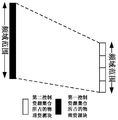
- the frequency domain range of the first control resource set in the embodiment is described below with reference to FIG. 6A.
- the frequency domain range of the second control resource set includes four physical resource blocks, and the first BWP and the second BWP.
- the subcarrier spacing is the same, both are N, that is, the frequency domain range of the first control resource set also includes four physical resource blocks, and the bandwidth of the frequency domain range of the first control resource set and the frequency domain range of the second control resource set
- the bandwidth of the second control resource set in the frequency domain may be continuous (for example, 4 physical resource blocks are occupied), or may be discontinuous (for example, only occupied)
- the first, third, and fourth physical resource blocks, the physical resource blocks occupied by the first control resource set in the frequency domain may be continuous or discontinuous, and the specific implementation manner is the same as the second control resource set. The repetitions are not repeated here.
- the bandwidth of the frequency domain range of the first control resource set is equal to the second control configured by the network device on the second BWP.
- the bandwidth of the frequency domain range of the resource set is multiplied by a predetermined scaling factor, or the number of physical resource blocks included in the frequency domain range of the first control resource set and the physical resource blocks included in the frequency domain range of the second control resource set
- the scaling factor is equal to the ratio of the subcarrier spacing of the first BWP to the subcarrier spacing of the second BWP, wherein the physical resource blocks occupied by the first control resource set and/or the second control resource set are consecutive Or discontinuous, wherein the bandwidth of the frequency domain range may be represented by multiplying the number of physical resource blocks by a frequency domain range (12* subcarrier spacing) of one physical resource block, where the number of physical resource blocks included in the frequency domain range is equal to Equal to the highest index of the physical resource block occupied by the control resource set minus the lowest index plus
- the frequency domain range of the first control resource set in the embodiment is described below with reference to FIG. 6B.
- the subcarrier spacing M of the first BWP is the ⁇ (scaling factor) times of the subcarrier spacing N of the second BWP.
- the bandwidth of the frequency domain range of the second control resource set is 12*4N, and the bandwidth of the frequency domain range of the first control resource set is 12*4M, that is, equal to 12*4 ⁇ N, where the frequency domain range of the first control resource set is
- the number of physical resource blocks included is the same as the number of physical resource blocks included in the frequency domain range of the second control resource set, and is 4; the physical resource blocks occupied by the second control resource set in the frequency domain range may be consecutive (For example, 4 physical resource blocks are occupied), or may be discontinuous (for example, occupy only the first, third, and fourth physical resource blocks), and the first control resource set occupies the physical resource block in the frequency domain.
- the embodiment may be the same as the second control resource set, and the repeated description will not be repeated.
- determining that the first starting position on the predetermined resource that the data can be mapped is the frequency domain range of the first control resource set configured on the first BWP.
- the second starting position thus, more terminal devices can receive and share the common message, saving system resource overhead, and can also be used for receiving the dedicated message of the terminal device to ensure the robustness of the BWP handover. , solved the existing problems.
- FIG. 7 is a flowchart of a resource configuration method according to Embodiment 3, which is applied to a network device side. As shown in Figure 7, the method includes:
- Step 701 Send configuration information of at least one frequency domain offset of the network device configuration relative to a starting position of the second BWP to the terminal device.
- the network device may pre-configure at least one of the frequency domain offsets, and add the start position of the second BWP to the at least one frequency domain offset as a starting position of the at least one virtual second BWP.
- the terminal device For the terminal device to determine the starting position of the frequency domain scheduling according to the starting position of the at least one virtual second BWP, the specific implementation manner of the terminal device side is described in the following embodiment 4. The following specifically describes how the network device configures the at least Configuration information for a frequency domain offset.
- the starting position of the second BWP may be represented by the index #Z or the frequency P of the physical resource block, that is, the starting position of the second BWP is the frequency domain starting position of the physical resource block with the lowest index.
- the index of the physical resource block with the lowest index is #Z.
- the frequency domain offset may be represented by the number of physical resource blocks, for example, the configuration information includes Y frequency domain offsets. , respectively, 1, 2, 3 acrossY, where 1, 2, 3 VietnameseY represents the number of physical resource blocks, and according to the configuration information, the at least one virtual second BWP can be determined.
- the starting position is #Z+1, #Z+2, #Z+3, ..., #Z+Y, which is merely illustrative here, and the embodiment is not limited thereto; in one embodiment,
- the frequency domain offset may be represented by the number of the physical resource blocks and the subcarrier spacing, and the subcarrier spacing may be equal to the subcarrier spacing of the second BWP, or may be configured as needed, and the embodiment is not limited thereto.
- the information includes Y frequency domain offsets and subcarrier spacings N, which are 1, 2, 3, ..., Y, respectively, where 1, 2, 3, ..., Y represent physical
- the number of the source blocks may be determined according to the configuration information, and the starting position of the at least one virtual second BWP is P+1*12*N, P+2*12*N,..., P+Y*12* N;
- the frequency domain offset may be directly represented by a frequency offset, which is not exemplified herein.
- the number of Ys can be determined as needed, and the embodiment is not limited thereto.
- the configuration information may be sent by remaining Minimum System Information (RMSI) and/or RRC signaling.
- RMSI remaining Minimum System Information
- the configuration information may be respectively carried by RMSI or RRC, or may be performed by RMSI and
- the RRC jointly carries the configuration information, where the RMSI and the RRC respectively carry a part of the information in the configuration information, for example, the RMSI carries the at least one frequency domain offset, and the RRC identifies the at least one frequency domain offset by an index, or the bit
- the bitmap indicates the available virtual BWP, and the virtual BWP is a virtual result of the second BWP after the frequency domain offset.
- the embodiment is not limited thereto.
- the specific implementation manner of the second BWP may refer to Embodiment 1, and is not repeated here.
- the network device configures the starting position of the at least one virtual second BWP for the terminal device, so that the terminal device determines the starting position of the frequency domain scheduling according to the virtual starting position, thereby enabling A plurality of terminal devices receive and share a common message, which saves system resource overhead, and can also be used to receive a dedicated message of the terminal device to ensure robustness in BWP handover and solve the existing problems.
- FIG. 8 is a flowchart of a resource scheduling method according to Embodiment 4, which is applied to a terminal device side. As shown in Figure 8, the method includes:
- Step 801 Receive downlink control information carried by the first control resource set on the first BWP.
- Step 802 When the size of the downlink control information is determined by the second BWP, determine that the first starting position of the frequency domain scheduling on the first BWP is the third starting position included in the first BWP, and the third The starting position is equal to a starting position plus frequency domain offset of the second control resource set configured by the network device on the second BWP;
- the size of the downlink control information is determined by the second BWP, and when the first BWP includes the second BWP, determining that the first starting location is a starting location of the second BWP.
- step 801 can refer to step 201 in Embodiment 1, and details are not described herein again.
- step 802 when the size of the downlink control information is determined by the second BWP, determining that the first start position of the frequency domain scheduling on the first BWP is included in the first BWP a third starting position, where the third starting position is equal to a starting position plus frequency domain offset of the second control resource set configured by the network device on the second BWP.
- the size of the downlink control information is determined by the second BWP.
- the second BWP For specific implementations, reference may be made to Embodiment 1, and details are not described herein again.
- the method further includes (not shown): configuration information of the network device configured with respect to at least one frequency domain offset of the starting position of the second BWP, wherein the specific content of the configuration information and the sending For the manner, refer to Embodiment 3, and details are not described herein again.
- the third starting position is equal to a start location plus frequency domain offset of the second control resource set configured by the network device on the second BWP, where the frequency domain offset may be determined according to the configuration information.
- the specific implementation manner of the third starting position may refer to the starting position of the virtual second BWP in Embodiment 3, and the content thereof is referred to herein, and details are not described herein again.
- the third starting position is used as the first starting position.
- a start position where a plurality of (at least two) third start positions are included in the first BWP, that is, when a plurality of third start positions are in a frequency domain range of the first BWP, one of the third positions may be selected.
- the starting position is used as the first starting position, for example, the third starting position with the highest or lowest frequency domain position is selected as the first starting position, but this embodiment is not limited thereto, and the third position of other positions may also be selected.
- the starting position is taken as the first starting position.
- step 802 another implementation manner of step 802 is that the size of the downlink control information is determined by the second BWP, and when the first BWP includes the second BWP, determining that the first starting location is the first The starting position of the second BWP.
- the first BWP includes the second BWP, that is, the frequency domain range of the BWP falls within the frequency domain of the first BWP
- determining that the first starting position is the starting position of the second BWP, that is, The first starting position is aligned with the starting position of the second BWP.
- the starting position of the second BWP may be determined according to the prior art, and may be represented by using frequency information, or a physical resource block index (the lowest index of the PRB occupied by the second BWP), and details are not described herein again.
- the number of the maximum contiguous physical resource blocks that the terminal device can schedule is the number of consecutive physical resource blocks occupied by the second BWP, and is scheduled according to the subcarrier spacing of the first BWP, as described above.
- "Can" indicates the frequency domain width that the terminal device can schedule, but it does not indicate the resources that the data actually receives.
- the specific implementation manner of the first BWP and the second BWP may refer to Embodiment 1, and is not repeated here.
- the method may further include (optional, not shown): receiving a public message and/or a dedicated message on the first BWP, in this step, according to the first starting position in step 802 as a scheduling
- the starting point in combination with the resource allocation information in the DCI, receives the public information on the PDSCH of the first BWP.
- the network device configures the starting position of the at least one virtual second BWP for the terminal device, so that the terminal device determines the starting position of the frequency domain scheduling according to the virtual starting position, thereby enabling A plurality of terminal devices receive and share a common message, which saves system resource overhead, and can also be used to receive a dedicated message of the terminal device to ensure robustness in BWP handover and solve the existing problems.
- the fifth embodiment further provides a data transmitting apparatus. Since the principle of solving the problem is similar to the method of the second embodiment, the specific implementation may refer to the implementation of the method of the second embodiment, and the description of the same portions is not repeated.
- Figure 9 is a diagram showing the data transmitting apparatus of the fifth embodiment. As shown in FIG. 9, the apparatus 900 includes:
- a first sending unit 901 configured to send downlink control information to the terminal device on the first BWP;
- a data mapping unit 902 for mapping data onto a predetermined resource; wherein, when the size of the downlink control information is determined by the second BWP, the first time on the predetermined resource that the data can be mapped to The start position is a second start position of a frequency domain range of the first control resource set configured on the first BWP;
- the second sending unit 903 is configured to send the data to the terminal device on the predetermined resource.
- the first starting location is a lowest index of a physical resource block occupied by the predetermined resource
- the data includes a public message and/or a dedicated message.
- the data mapping unit 902 determines the frequency domain width of the predetermined resource to which the data can be mapped according to the size of the second BWP.
- the data mapping unit 902 determines that the number of the maximum contiguous physical resource blocks occupied by the frequency domain width of the predetermined resource to which the data can be mapped is equal to the number of physical resource blocks occupied by the second BWP. .
- the data mapping unit 902 maps the data to the predetermined resource by using a distributed mapping manner
- the data mapping unit distributes the data to the predetermined frequency domain of the predetermined resource.
- the predetermined frequency domain range is equal to the size of the second BWP.
- the device may further include: (not shown)
- a third sending unit configured to send, to the terminal device, first configuration information of the first control resource set configured by the network device on the first BWP; the first configuration information includes frequency domain range information of the first control resource set;
- the frequency domain range of the first control resource set and the second control resource configured by the network device on the second BWP when the size of the downlink control information carried by the first control resource set is determined by the second BWP The frequency domain range of the set is the same, or the frequency domain range of the first control resource set is equal to a frequency domain range of the second control resource set configured by the network device on the second BWP multiplied by a predetermined scaling factor.
- the bandwidth of the frequency domain range of the first control resource set and the network device are configured on the second BWP.
- the bandwidth of the frequency domain range of the second control resource set is the same; when the subcarrier spacing of the first BWP is different from the subcarrier spacing of the second BWP, the bandwidth of the frequency domain range of the first control resource set is equal to the The bandwidth of the frequency domain range of the second set of control resources configured by the network device on the second BWP is multiplied by a predetermined scaling factor.
- the scaling factor is equal to a ratio of a subcarrier spacing of the first BWP to a subcarrier spacing of the second BWP.
- the frequency domain range of the first control resource set includes the same number of physical resource blocks as the frequency domain range of the second control resource set.
- the physical resource blocks occupied by the first control resource set and/or the second control resource set are consecutive or non-contiguous.
- the second BWP is an initial BWP; the first BWP is a currently activated BWP.
- the size of the downlink control information is determined by the second BWP to include:
- the format of the downlink control information is 1-0, and the downlink control information is detected in a common search space; or
- the format of the downlink control information is 1-0, and the downlink control information is detected in a dedicated search space.
- the specific implementation manners of the first sending unit 901, the data mapping unit 902, and the second sending unit 903 may refer to the embodiment, step 501-503 in FIG. 2, and details are not described herein again.
- determining that the first starting position on the predetermined resource that the data can be mapped is the frequency domain range of the first control resource set configured on the first BWP.
- the second starting position thus, more terminal devices can receive and share the common message, saving system resource overhead, and can also be used for receiving the dedicated message of the terminal device to ensure the robustness of the BWP handover. , solved the existing problems.
- the present embodiment provides a network device.
- the method for solving the problem is similar to the method of the second embodiment. Therefore, the specific implementation may be implemented by referring to the method in the second embodiment.
- FIG. 10 is a schematic structural diagram of a network device according to an embodiment of the present invention.
- network device 1000 can include a central processing unit (CPU) 1001 and memory 1002; and memory 1002 is coupled to central processing unit 1001.
- the memory 1002 can store various data; in addition, a program for data processing is stored, and the program is executed under the control of the central processing unit 1001 to transmit related information.
- the functionality of device 900 can be integrated into central processor 1001.
- the central processing unit 1001 can be configured to implement the data transmission method of Embodiment 2.
- the central processing unit 1001 may be configured to: send downlink control information to the terminal device on the first BWP; map the data to the predetermined resource; wherein, when the size of the downlink control information is determined by the second BWP, the The first starting position on the predetermined resource to which the data can be mapped is a second starting position of a frequency domain range of the first control resource set configured on the first BWP; and the terminal device is sent on the predetermined resource The data.
- the central processing unit 1001 may be configured to: determine a frequency domain width of the predetermined resource to which the data can be mapped, according to a size of the second BWP, a maximum frequency domain width of the predetermined resource to which the data can be mapped
- the number of consecutive physical resource blocks is equal to the number of physical resource blocks occupied by the second BWP.
- the central processing unit 1001 can be configured to: when the data is mapped onto the predetermined resource using a distributed mapping manner, the data is distributedly mapped to a predetermined frequency domain range of the predetermined resource, the predetermined frequency The domain range is equal to the size of the second BWP.
- the central processing unit 1001 may be configured to: send, to the terminal device, first configuration information of the first control resource set configured by the network device on the first BWP; the first configuration information includes a frequency domain of the first control resource set Range information
- the frequency domain range of the first control resource set and the second control resource configured by the network device on the second BWP when the size of the downlink control information carried by the first control resource set is determined by the second BWP The frequency domain range of the set is the same, or the frequency domain range of the first control resource set is equal to a frequency domain range of the second control resource set configured by the network device on the second BWP multiplied by a predetermined scaling factor.
- the foregoing apparatus 900 may be configured separately from the central processing unit 1001.
- the apparatus 900 may be configured as a chip connected to the central processing unit 1001, such as the unit shown in FIG. 10, through the central processing unit 1001. Control is implemented to implement the functionality of device 900.
- the network device 1000 may further include: a transceiver 1003, an antenna 1004, and the like; wherein the functions of the foregoing components are similar to those of the prior art, and details are not described herein again. It should be noted that the network device 1000 does not necessarily have to include all the components shown in FIG. 10; in addition, the network device 1000 may further include components not shown in FIG. 10, and reference may be made to the prior art.
- determining that the first starting position on the predetermined resource that the data can be mapped is the frequency domain range of the first control resource set configured on the first BWP.
- the second starting position thus, more terminal devices can receive and share the common message, saving system resource overhead, and can also be used for receiving the dedicated message of the terminal device to ensure the robustness of the BWP handover. , solved the existing problems.
- the seventh embodiment further provides a resource configuration apparatus. Since the principle of solving the problem is similar to the method of the third embodiment, the specific implementation may refer to the implementation of the method of the third embodiment, and the description of the same portions is not repeated.
- FIG. 11 is a schematic structural diagram of a resource configuration apparatus according to an embodiment of the present invention. As shown in FIG. 11, the apparatus includes:
- the second sending unit 1101 is configured to send, to the terminal device, configuration information of the network device configured with respect to at least one frequency domain offset of the starting position of the second BWP.
- the second sending unit 1101 sends the configuration information by using a broadcast message or a radio resource control signaling.
- the frequency domain offset may be represented by the number of physical resource blocks.
- the specific implementation manner of the second sending unit 1101 may refer to Embodiment 3.
- the specific meanings of the configuration information, the second BWP, the starting position, and the frequency domain offset refer to Embodiment 3, where Let me repeat.
- the network device configures the starting position of the at least one virtual second BWP for the terminal device, so that the terminal device determines the starting position of the frequency domain scheduling according to the virtual starting position, thereby enabling A plurality of terminal devices receive and share a common message, which saves system resource overhead, and can also be used to receive a dedicated message of the terminal device to ensure robustness in BWP handover and solve the existing problems.
- the embodiment 8 provides a network device.
- the method for solving the problem is similar to the method of the third embodiment. Therefore, the specific implementation may be implemented by referring to the method in the third embodiment.
- FIG. 12 is a schematic diagram showing the structure of a network device according to an embodiment of the present invention.
- network device 1200 can include a central processing unit (CPU) 1201 and a memory 1202; and memory 1202 is coupled to central processing unit 1201.
- the memory 1202 can store various data; in addition, a program for data processing is stored, and the program is executed under the control of the central processor 1201 to transmit related information.
- the functionality of device 1100 can be integrated into central processor 1201.
- the central processing unit 1201 may be configured to implement the resource configuration method of Embodiment 3.
- the central processor 1201 can be configured to transmit, to the terminal device, configuration information of the network device configuration with respect to at least one frequency domain offset of the starting position of the second BWP.
- the central processor 1201 can also be configured to transmit the configuration information via a broadcast message or radio resource control signaling.
- the above device 1100 can be configured separately from the central processing unit 1201.
- the device 1100 can be configured as a chip connected to the central processing unit 1201, such as the unit shown in FIG. 12, through the central processing unit 1201. Controls to implement the functionality of device 1100.
- the network device 1200 may further include: a transceiver 1203, an antenna 1204, and the like; wherein the functions of the foregoing components are similar to the prior art, and details are not described herein again. It should be noted that the network device 1200 does not have to include all the components shown in FIG. 12; in addition, the network device 1200 may further include components not shown in FIG. 12, and reference may be made to the prior art.
- the network device configures the starting position of the at least one virtual second BWP for the terminal device, so that the terminal device determines the starting position of the frequency domain scheduling according to the virtual starting position, thereby enabling A plurality of terminal devices receive and share a common message, which saves system resource overhead, and can also be used to receive a dedicated message of the terminal device to ensure robustness in BWP handover and solve the existing problems.
- the embodiment 9 also provides a resource scheduling apparatus. Since the principle of solving the problem is similar to the method of Embodiment 1, the specific implementation may refer to the implementation of the method of Embodiment 1, and the description of the same portions is not repeated.
- FIG. 13 is a schematic structural diagram of a resource scheduling apparatus according to an embodiment of the present invention. As shown in FIG. 13, the apparatus includes:
- a first receiving unit 1301, configured to receive downlink control information carried by the first control resource set on the first BWP;
- a determining unit 1302 configured to determine, when the size of the downlink control information is determined by the second BWP, that the first starting position of the frequency domain scheduling on the first BWP is the frequency domain range of the first control resource set Second starting position.
- the specific implementation manners of the first receiving unit 1301 and the determining unit 1302 may refer to steps 201-202 of Embodiment 1, and details are not described herein again.
- the determining unit 1302 determines the frequency domain width that can be scheduled according to the size of the second BWP.
- the determining unit 1302 determines that the number of the maximum contiguous physical resource blocks occupied by the frequency domain width that can be scheduled is equal to the number of physical resource blocks occupied by the second BWP.
- the device may further include: (not shown)
- a second receiving unit for receiving a public message and/or a dedicated message on the first BWP.
- the device may further include: (not shown)
- a third receiving unit configured to receive first configuration information of the first control resource set configured on the first BWP that is sent by the network device, where the first configuration information includes frequency domain range information of the first control resource set;
- the frequency domain range of the first control resource set and the second control resource configured by the network device on the second BWP when the size of the downlink control information carried by the first control resource set is determined by the second BWP The frequency domain range of the set is the same, or the frequency domain range of the first control resource set is equal to a frequency domain range of the second control resource set configured by the network device on the second BWP multiplied by a predetermined scaling factor.
- the specific implementation manner of the second BWP, the first BWP, and the downlink control information may refer to Embodiment 1, and details are not described herein again.
- the terminal device aligns the starting position of the frequency domain scheduling with the frequency domain starting position of the control resource set configured on the other BWP, thereby enabling more terminal devices to receive and Sharing common messages saves system resource overhead, and can also be used to receive dedicated messages of terminal devices to ensure robustness in BWP handover and solve current problems.
- the embodiment 10 provides a terminal device.
- the method for solving the problem is similar to the method of the first embodiment. Therefore, the specific implementation may be implemented by referring to the method in the first embodiment.
- FIG. 14 is a schematic diagram showing the structure of a terminal device according to an embodiment of the present invention.
- user equipment 1400 can include a central processing unit (CPU) 1401 and a memory 1402; and memory 1402 is coupled to central processing unit 1401.
- the memory 1402 can store various data; in addition, a program for data processing is stored, and the program is executed under the control of the central processor 1401 to receive related information.
- the functionality of device 1300 can be integrated into central processor 1401.
- the central processing unit 1401 may be configured to implement the resource scheduling method described in Embodiment 1.
- the central processing unit 1401 may be configured to: receive downlink control information carried by the first control resource set on the first BWP; and determine, on the first BWP, when the size of the downlink control information is determined by the second BWP
- the first starting position of the frequency domain scheduling is a second starting position of the frequency domain range of the first control resource set.
- the central processing unit 1401 may be configured to determine a frequency domain width that can be scheduled according to the size of the second BWP when the size of the downlink control information is determined by the second BWP.
- the central processing unit 1401 may be configured to: determine that the number of the largest contiguous physical resource blocks occupied by the frequency domain width that can be scheduled is equal to the number of physical resource blocks occupied by the second BWP.
- central processor 1401 can be configured to receive a public message and/or a dedicated message on the first BWP.
- the central processing unit 1401 may be configured to: receive, by the network device, first configuration information of the first control resource set configured on the first BWP, where the first configuration information includes a frequency domain range of the first control resource set information;
- the frequency domain range of the first control resource set and the second control resource configured by the network device on the second BWP when the size of the downlink control information carried by the first control resource set is determined by the second BWP The frequency domain range of the set is the same, or the frequency domain range of the first control resource set is equal to a frequency domain range of the second control resource set configured by the network device on the second BWP multiplied by a predetermined scaling factor.
- the specific implementation manner of the second BWP, the first BWP, and the downlink control information may refer to Embodiment 1, and details are not described herein again.
- the foregoing apparatus 1300 may be configured separately from the central processing unit 1401.
- the apparatus 1300 may be configured as a chip connected to the central processing unit 1401, such as the unit shown in FIG. 14, through the central processing unit 1401. Control is implemented to implement the functionality of device 1300.
- the user equipment 1400 may further include a communication module 1403, an input unit 1404, a display 1406, an audio processor 1405, an antenna 1407, a power source 1408, and the like.
- the functions of the above components are similar to those of the prior art, and are not described herein again. It should be noted that the user equipment 1400 does not have to include all of the components shown in FIG. 14; in addition, the user equipment 1400 may also include components not shown in FIG. 14, and reference may be made to the prior art.
- the terminal device aligns the starting position of the frequency domain scheduling with the frequency domain starting position of the control resource set configured on the other BWP, thereby enabling more terminal devices to receive and Sharing common messages saves system resource overhead, and can also be used to receive dedicated messages of terminal devices to ensure robustness in BWP handover and solve current problems.
- the embodiment 11 further provides a resource scheduling apparatus. Since the principle of solving the problem is similar to the method of the embodiment 4, the specific implementation may refer to the implementation of the method of the embodiment 4, and the description of the same portions is not repeated.
- FIG. 15 is a schematic structural diagram of a resource scheduling apparatus according to an embodiment of the present invention. As shown in FIG. 15, the apparatus includes:
- a first receiving unit 1501 configured to receive downlink control information carried by the first control resource set on the first BWP;
- a determining unit 1502 configured to determine, when the size of the downlink control information is determined by the second BWP, that the first starting position of the frequency domain scheduling on the first BWP is the third starting position included in the first BWP
- the third start position is equal to a start position plus frequency domain offset of the second control resource set configured by the network device on the second BWP; or the size of the downlink control information is determined by the second BWP, and
- the first BWP includes the second BWP, the first starting position is determined to be a starting position of the second BWP.
- the specific implementation manners of the first receiving unit 1501 and the determining unit 1502 may refer to steps 801-802 of Embodiment 4, and details are not described herein again.
- the determining unit 1502 determines that the number of the maximum contiguous physical resource blocks that can be scheduled is equal to the contiguous physical resource blocks occupied by the second BWP. Number.
- the device may further include:
- a second receiving unit (optional, not shown) for receiving a public message and/or a dedicated message on the first BWP.
- the device may further include:
- a fourth receiving unit configured to receive configuration information of at least one of the frequency domain offsets of the network device configuration relative to a starting position of the second BWP.
- the determining unit 1502 determines that the first starting position is the highest or lowest third starting position.
- the fourth receiving unit may receive the configuration information by using a broadcast message or a radio resource control signaling.
- the specific implementation manners of the second receiving unit and the fourth receiving unit may refer to Embodiment 4, and details are not described herein again.
- the network device configures the starting position of the at least one virtual second BWP for the terminal device, so that the terminal device determines the starting position of the frequency domain scheduling according to the virtual starting position, thereby enabling A plurality of terminal devices receive and share a common message, which saves system resource overhead, and can also be used to receive a dedicated message of the terminal device to ensure robustness in BWP handover and solve the existing problems.
- the embodiment 12 provides a terminal device.
- the method for solving the problem is similar to the method in the embodiment 4. Therefore, the specific implementation may be implemented by referring to the method in the embodiment 4.
- FIG. 16 is a schematic diagram showing the structure of a terminal device according to an embodiment of the present invention.
- user device 1600 can include a central processing unit (CPU) 1601 and memory 1602; and memory 1602 coupled to central processor 1601.
- the memory 1602 can store various data; in addition, a program for data processing is stored, and the program is executed under the control of the central processing unit 1601 to receive related information.
- the functionality of device 1500 can be integrated into central processor 1601.
- the central processing unit 1601 may be configured to implement the resource scheduling method described in Embodiment 4.
- the central processing unit 1601 may be configured to: receive downlink control information carried by the first control resource set on the first BWP; and uplink the first BWP when the size of the downlink control information is determined by the second BWP.
- the first starting position of the domain scheduling is a third starting location included in the first BWP, and the third starting location is equal to a starting location of the second control resource set configured by the network device on the second BWP. Offset; or the size of the downlink control information is determined by the second BWP, and when the first BWP includes the second BWP, determining that the first starting position is the starting position of the second BWP.
- the central processing unit 1601 may be configured to: when the size of the downlink control information is determined by the second BWP, determine that the number of the maximum contiguous physical resource blocks that can be scheduled is equal to the contiguous physical resource blocks occupied by the second BWP. The number.
- central processor 1601 can be configured to receive a common message and/or a dedicated message on the first BWP.
- the central processor 1601 can be configured to receive configuration information of at least one of the frequency domain offsets of the network device configuration relative to a starting location of the second BWP.
- the central processor 1601 can be configured to determine that the first starting position is the highest or lowest third starting position when the first BWP includes at least two third starting positions.
- the central processor 1601 can be configured to receive the configuration information via a broadcast message or radio resource control signaling.
- the foregoing apparatus 1500 may be configured separately from the central processing unit 1601.
- the apparatus 1500 may be configured as a chip connected to the central processing unit 1601, such as the unit shown in FIG. 16, through the central processing unit 1601. Control is implemented to implement the functionality of device 1500.
- the user equipment 1600 may further include a communication module 1603, an input unit 1604, a display 1606, an audio processor 1605, an antenna 1607, a power source 1608, and the like.
- the functions of the above components are similar to those of the prior art, and are not described herein again.
- the user equipment 1600 does not necessarily have to include all of the components shown in FIG. 16; further, the user equipment 1600 may also include components not shown in FIG. 16, and reference may be made to the prior art.
- the network device configures the starting position of the at least one virtual second BWP for the terminal device, so that the terminal device determines the starting position of the frequency domain scheduling according to the virtual starting position, thereby enabling A plurality of terminal devices receive and share a common message, which saves system resource overhead, and can also be used to receive a dedicated message of the terminal device to ensure robustness in BWP handover and solve the existing problems.
- the embodiment 13 provides a communication system. As shown in FIG. 1, the communication system includes a network device 101 and/or a terminal device 102.
- the specific implementation of the network device 101 may be the network device 1000 or 1200 in the embodiment 6 or 8.
- the specific implementation manner of the terminal device 102 may refer to the terminal device 1400 or 1600 in the embodiment 10 or 12, and the content thereof. This is incorporated herein and will not be repeated here.
- the embodiment of the present invention further provides a storage medium storing a computer readable program, wherein the computer readable program causes the data transmitting device or the network device to execute the data transmitting method described in Embodiment 2.
- the embodiment of the present invention further provides a computer readable program, wherein the program causes the data transmitting device or the network device to perform the data transmission described in Embodiment 2 when the program is executed in a resource configuration device or a network device method.
- the embodiment of the present invention further provides a storage medium storing a computer readable program, wherein the computer readable program causes a resource configuration device or a network device to execute the resource configuration method described in Embodiment 3.
- the embodiment of the present invention further provides a computer readable program, wherein the program causes the resource configuration device or the network device to perform the resource configuration described in Embodiment 3 when the program is executed in a resource configuration device or a network device method.
- the embodiment of the present invention further provides a storage medium storing a computer readable program, wherein the computer readable program causes the resource determining apparatus or the user equipment to execute the resource scheduling method described in Embodiment 1 or 4.
- the embodiment of the present invention further provides a computer readable program, wherein the program causes the resource determining apparatus or user equipment to perform the method described in Embodiment 1 or 4 when the program is executed in a resource determining apparatus or a user equipment Resource scheduling method.
- the above apparatus and method of the present invention may be implemented by hardware or by hardware in combination with software.
- the present invention relates to a computer readable program that, when executed by a logic component, enables the logic component to implement the apparatus or components described above, or to cause the logic component to implement the various methods described above Or steps.
- the present invention also relates to a storage medium for storing the above program, such as a hard disk, a magnetic disk, an optical disk, a DVD, a flash memory, or the like.
- Each processing method in each device described in connection with the embodiments of the present invention may be directly embodied as hardware, a software module executed by a processor, or a combination of both.
- one or more of the functional blocks shown in Figures 9-17 and/or one or more combinations of functional blocks may correspond to various software modules of a computer program flow, or to individual hardware modules.
- These software modules may correspond to the respective steps shown in Figures 2, 5, 7, and 8, respectively.
- These hardware modules can be implemented, for example, by curing these software modules using a Field Programmable Gate Array (FPGA).
- FPGA Field Programmable Gate Array
- the software module can reside in RAM memory, flash memory, ROM memory, EPROM memory, EEPROM memory, registers, hard disk, removable disk, CD-ROM, or any other form of storage medium known in the art.
- a storage medium can be coupled to the processor to enable the processor to read information from, and write information to, the storage medium; or the storage medium can be an integral part of the processor.
- the processor and the storage medium can be located in an ASIC.
- the software module can be stored in the memory of the mobile terminal or in a memory card that can be inserted into the mobile terminal.
- the software module can be stored in the MEGA-SIM card or a large-capacity flash memory device.
- One or more of the functional blocks described with respect to Figures 9-17 and/or one or more combinations of functional blocks may be implemented as a general purpose processor, digital signal processor (DSP) for performing the functions described herein.
- DSP digital signal processor
- ASIC application specific integrated circuit
- FPGA field programmable gate array
- One or more of the functional blocks described with respect to Figures 9-17 and/or one or more combinations of functional blocks may also be implemented as a combination of computing devices, e.g., a combination of a DSP and a microprocessor, multiple microprocessors One or more microprocessors in conjunction with DSP communication or any other such configuration.
- Attachment 1 a resource scheduling method, comprising:
- the frequency domain width that can be scheduled is determined according to the size of the second BWP.
- a public message and/or a dedicated message is received on the first BWP.
- the network device Receiving, by the network device, first configuration information of the first control resource set configured on the first BWP; the first configuration information includes frequency domain range information of the first control resource set;
- the frequency domain range of the first control resource set and the network device are configured on the second BWP when the size of the downlink control information carried by the first control resource set is determined by the second BWP.
- the frequency domain range of the second control resource set is the same, or the frequency domain range of the first control resource set is equal to the frequency domain range of the second control resource set configured by the network device on the second BWP, multiplied by a predetermined scaling factor.
- the size of the downlink control information is determined by the second BWP to include:
- the format of the downlink control information is 1-0, and the downlink control information is detected in a common search space; or
- the format of the downlink control information is 1-0, and the downlink control information is detected in a dedicated search space.
- the second configuration information includes a physical resource block highest index of the first BWP, and a physicality between the highest index and the first starting location
- the number of resource blocks is greater than or equal to the number of physical resource blocks occupied by the second BWP.
- Appendix 9 a data transmission method, comprising:
- the first starting location on the predetermined resource to which the data can be mapped is configured in the first a second starting position of a frequency domain range of the first set of control resources on a BWP;
- determining a frequency domain width of the predetermined resource to which the data can be mapped occupies a maximum number of consecutive physical resource blocks equal to the second BWP The number of physical resource blocks.
- the predetermined frequency domain range is equal to the size of the second BWP in the frequency domain.
- the data comprises a public message and/or a dedicated message.
- the terminal device Transmitting, by the terminal device, first configuration information of the first control resource set configured by the network device on the first BWP; the first configuration information includes frequency domain range information of the first control resource set;
- the frequency domain range of the first control resource set and the network device are configured on the second BWP when the size of the downlink control information carried by the first control resource set is determined by the second BWP.
- the frequency domain range of the second control resource set is the same, or the frequency domain range of the first control resource set is equal to the frequency domain range of the second control resource set configured by the network device on the second BWP, multiplied by a predetermined scaling factor.
- the frequency domain range of the first control resource set is the same when the subcarrier spacing of the first BWP is the same as the subcarrier spacing of the second BWP
- the bandwidth is the same as the bandwidth of the frequency domain range of the second control resource set configured by the network device on the second BWP; the subcarrier spacing of the first BWP is different from the subcarrier spacing of the second BWP.
- the bandwidth of the frequency domain range of the first control resource set is equal to the bandwidth of the frequency domain range of the second control resource set configured by the network device on the second BWP multiplied by a predetermined scaling factor.
- the scaling factor is equal to a ratio of a subcarrier spacing of the first BWP to a subcarrier spacing of the second BWP.
- the frequency domain range of the first control resource set includes a physical resource block and the physical resource block included in a frequency domain range of the second control resource set The number is the same.
- a resource scheduling method comprising:
- the configuration information includes frequency domain range information of the first control resource set
- the frequency domain range of the first control resource set and the network device are configured on the second BWP when the size of the downlink control information carried by the first control resource set is determined by the second BWP.
- the frequency domain range of the second control resource set is the same, or the frequency domain range of the first control resource set is equal to the frequency domain range of the second control resource set configured by the network device on the second BWP, multiplied by a predetermined scaling factor.
- Supplementary note 22 A resource configuration method, wherein the method includes:
- the configuration information of the at least one frequency domain offset of the network device configuration relative to the start position of the second BWP is transmitted to the terminal device.
- Supplementary note 23 is a communication system, the communication system comprising a terminal device comprising the resource scheduling device of claim 1 or 20.
Abstract
L'invention concerne un procédé de planification de ressources, un procédé de transmission de données et un dispositif associé, ainsi qu'un système de communication. Le dispositif de planification de ressources comprend une première unité de réception utilisée pour recevoir, sur une première partie de bande passante (BWP), des informations de commande de liaison descendante transportées sur un premier ensemble de ressources de commande ; et une unité de détermination utilisée, lors de l'établissement de la taille des informations de commande de liaison descendante par une seconde BWP, pour déterminer qu'une première position initiale à laquelle une planification de domaine fréquentiel est effectuée sur la première BWP est une seconde position initiale dans une plage de domaine fréquentiel du premier ensemble de ressources de commande. L'invention permet à un plus grand nombre d'appareils terminaux de recevoir et de partager un message commun, ce qui permet de réduire le surdébit de ressources système. L'invention peut également être utilisée pour recevoir un message spécifique d'un appareil terminal, garantissant ainsi une robustesse lors de la commutation entre les BWP, et résolvant les problèmes existants.
Priority Applications (4)
| Application Number | Priority Date | Filing Date | Title |
|---|---|---|---|
| PCT/CN2018/081627 WO2019191873A1 (fr) | 2018-04-02 | 2018-04-02 | Procédé de planification de ressources, procédé de transmission de données et dispositif associé, et système de communication |
| JP2020552796A JP7111171B2 (ja) | 2018-04-02 | 2018-04-02 | リソーススケジューリング方法、データ送信方法及びその装置、通信システム |
| CN201880091410.8A CN111919480B (zh) | 2018-04-02 | 2018-04-02 | 资源调度方法、数据发送方法及其装置、通信系统 |
| US17/031,336 US11588605B2 (en) | 2018-04-02 | 2020-09-24 | Resource scheduling method and apparatus, data transmission method and apparatus and communication system |
Applications Claiming Priority (1)
| Application Number | Priority Date | Filing Date | Title |
|---|---|---|---|
| PCT/CN2018/081627 WO2019191873A1 (fr) | 2018-04-02 | 2018-04-02 | Procédé de planification de ressources, procédé de transmission de données et dispositif associé, et système de communication |
Related Child Applications (1)
| Application Number | Title | Priority Date | Filing Date |
|---|---|---|---|
| US17/031,336 Continuation US11588605B2 (en) | 2018-04-02 | 2020-09-24 | Resource scheduling method and apparatus, data transmission method and apparatus and communication system |
Publications (1)
| Publication Number | Publication Date |
|---|---|
| WO2019191873A1 true WO2019191873A1 (fr) | 2019-10-10 |
Family
ID=68099867
Family Applications (1)
| Application Number | Title | Priority Date | Filing Date |
|---|---|---|---|
| PCT/CN2018/081627 WO2019191873A1 (fr) | 2018-04-02 | 2018-04-02 | Procédé de planification de ressources, procédé de transmission de données et dispositif associé, et système de communication |
Country Status (4)
| Country | Link |
|---|---|
| US (1) | US11588605B2 (fr) |
| JP (1) | JP7111171B2 (fr) |
| CN (1) | CN111919480B (fr) |
| WO (1) | WO2019191873A1 (fr) |
Families Citing this family (2)
| Publication number | Priority date | Publication date | Assignee | Title |
|---|---|---|---|---|
| CN115843120A (zh) * | 2022-01-19 | 2023-03-24 | 中兴通讯股份有限公司 | 一种资源配置方法、电子设备和存储介质 |
| CN117042155A (zh) * | 2022-04-29 | 2023-11-10 | 大唐移动通信设备有限公司 | 资源确定方法、装置、终端及网络侧设备 |
Citations (2)
| Publication number | Priority date | Publication date | Assignee | Title |
|---|---|---|---|---|
| CN107659994A (zh) * | 2017-09-05 | 2018-02-02 | 宇龙计算机通信科技(深圳)有限公司 | 资源指示方法、相关设备及通信系统 |
| US20180049203A1 (en) * | 2016-08-11 | 2018-02-15 | Samsung Electronics Co., Ltd. | Method and apparatus of data transmission in next generation cellular networks |
Family Cites Families (4)
| Publication number | Priority date | Publication date | Assignee | Title |
|---|---|---|---|---|
| US9949261B2 (en) * | 2009-10-15 | 2018-04-17 | Qualcomm Incorporated | Method and apparatus for conveying resource assignment for multiple system bandwidths |
| WO2018016907A1 (fr) * | 2016-07-21 | 2018-01-25 | 엘지전자 주식회사 | Procédé d'émission ou de réception d'informations de commande de liaison descendante dans un système de communication sans fil et dispositif associé |
| JP6861891B2 (ja) * | 2017-09-11 | 2021-04-21 | エルジー エレクトロニクス インコーポレイティド | 無線通信システムにおけるダウンリンク制御情報を送信する方法及び装置 |
| WO2019050379A1 (fr) * | 2017-09-11 | 2019-03-14 | Lg Electronics Inc. | Procédé et appareil de transmission d'informations de commande de liaison descendante dans un système de communication sans fil |
-
2018
- 2018-04-02 CN CN201880091410.8A patent/CN111919480B/zh active Active
- 2018-04-02 WO PCT/CN2018/081627 patent/WO2019191873A1/fr active Application Filing
- 2018-04-02 JP JP2020552796A patent/JP7111171B2/ja active Active
-
2020
- 2020-09-24 US US17/031,336 patent/US11588605B2/en active Active
Patent Citations (2)
| Publication number | Priority date | Publication date | Assignee | Title |
|---|---|---|---|---|
| US20180049203A1 (en) * | 2016-08-11 | 2018-02-15 | Samsung Electronics Co., Ltd. | Method and apparatus of data transmission in next generation cellular networks |
| CN107659994A (zh) * | 2017-09-05 | 2018-02-02 | 宇龙计算机通信科技(深圳)有限公司 | 资源指示方法、相关设备及通信系统 |
Non-Patent Citations (2)
| Title |
|---|
| ERICSSON: "Outcome of offline session on 7.1.3.1.4 (DCI contents and formats)", TSG-RAN WG1 #92, RL-1803369, 2 March 2018 (2018-03-02), XP051398538 * |
| ITRI: "Discussion on DCI format 0-0/0-1", 3GPP TSG RAN WG1 MEETING #92, RL-1802089, 2 March 2018 (2018-03-02), XP051396746 * |
Also Published As
| Publication number | Publication date |
|---|---|
| JP2021517427A (ja) | 2021-07-15 |
| US11588605B2 (en) | 2023-02-21 |
| CN111919480B (zh) | 2023-06-16 |
| US20210006383A1 (en) | 2021-01-07 |
| CN111919480A (zh) | 2020-11-10 |
| JP7111171B2 (ja) | 2022-08-02 |
Similar Documents
| Publication | Publication Date | Title |
|---|---|---|
| ES2812878T3 (es) | DRX y SPS para MTC con transmisiones agrupadas | |
| CN108347778B (zh) | 通信方法及装置 | |
| WO2018127021A1 (fr) | Procédé d'indication de ressources, équipement d'utilisateur et dispositif réseau | |
| JP2017532831A (ja) | Mtcデバイス動作のシステム及び方法 | |
| WO2018227483A1 (fr) | Procédé de configuration de ressources, procédé de détermination, dispositif associé, et système de communication | |
| CN111034287B (zh) | 资源配置方法、确定方法及其装置、通信系统 | |
| WO2019157663A1 (fr) | Procédé et dispositif permettant d'indiquer un emplacement de transmission d'une ressource de signal de référence, et système de communication | |
| EP3627733A1 (fr) | Procédé de communication, dispositif de réseau, et dispositif terminal | |
| CN110892767B (zh) | 资源指示方法、装置及通信系统 | |
| CN108811074B (zh) | 信息传输方法及装置 | |
| WO2018112918A1 (fr) | Procédé et appareil de commande de transmission de liaison montante, et système de communication | |
| JP6532932B2 (ja) | ユーザ端末、無線基地局及び無線通信方法 | |
| CN113273115B (zh) | 信息发送和接收方法以及装置 | |
| CN113330709B (zh) | 终端设备、网络设备及其中的方法 | |
| TW202008828A (zh) | 資源配置的方法和終端設備 | |
| US11678239B2 (en) | Communication method, base station, and terminal | |
| CN113517970A (zh) | 一种小区状态管理方法及装置、终端设备、网络设备 | |
| US11588605B2 (en) | Resource scheduling method and apparatus, data transmission method and apparatus and communication system | |
| KR20190060759A (ko) | Ran 프로필 인덱스를 시그널링하기 위한 방법 및 이를 사용하는 무선 통신 장비 | |
| WO2020029299A1 (fr) | Procédé d'indication d'interruption de données et appareil associé, et système de communication | |
| WO2020024298A1 (fr) | Procédé et appareil d'indication de planification de ressources, et système de communication | |
| WO2020006680A1 (fr) | Procédé et appareil d'indication de ressource ainsi que système de communication | |
| WO2019213969A1 (fr) | Procédé de détermination de ressource, dispositif associé et système de communications | |
| WO2018227596A1 (fr) | Procédé d'indication de ressource de domaine temporel, procédé de transmission de données et dispositif et système de communication | |
| WO2019232786A1 (fr) | Procédé d'indication de ressource, dispositif associé et système de communication |
Legal Events
| Date | Code | Title | Description |
|---|---|---|---|
| 121 | Ep: the epo has been informed by wipo that ep was designated in this application |
Ref document number: 18913835 Country of ref document: EP Kind code of ref document: A1 |
|
| ENP | Entry into the national phase |
Ref document number: 2020552796 Country of ref document: JP Kind code of ref document: A |
|
| NENP | Non-entry into the national phase |
Ref country code: DE |
|
| 122 | Ep: pct application non-entry in european phase |
Ref document number: 18913835 Country of ref document: EP Kind code of ref document: A1 |