WO2019189683A1 - Deodorization method - Google Patents
Deodorization method Download PDFInfo
- Publication number
- WO2019189683A1 WO2019189683A1 PCT/JP2019/013851 JP2019013851W WO2019189683A1 WO 2019189683 A1 WO2019189683 A1 WO 2019189683A1 JP 2019013851 W JP2019013851 W JP 2019013851W WO 2019189683 A1 WO2019189683 A1 WO 2019189683A1
- Authority
- WO
- WIPO (PCT)
- Prior art keywords
- circulation system
- water
- minutes
- supplying
- rinsing
- Prior art date
Links
Images


Classifications
-
- B—PERFORMING OPERATIONS; TRANSPORTING
- B67—OPENING, CLOSING OR CLEANING BOTTLES, JARS OR SIMILAR CONTAINERS; LIQUID HANDLING
- B67C—CLEANING, FILLING WITH LIQUIDS OR SEMILIQUIDS, OR EMPTYING, OF BOTTLES, JARS, CANS, CASKS, BARRELS, OR SIMILAR CONTAINERS, NOT OTHERWISE PROVIDED FOR; FUNNELS
- B67C7/00—Concurrent cleaning, filling, and closing of bottles; Processes or devices for at least two of these operations
- B67C7/0073—Sterilising, aseptic filling and closing
-
- B—PERFORMING OPERATIONS; TRANSPORTING
- B67—OPENING, CLOSING OR CLEANING BOTTLES, JARS OR SIMILAR CONTAINERS; LIQUID HANDLING
- B67C—CLEANING, FILLING WITH LIQUIDS OR SEMILIQUIDS, OR EMPTYING, OF BOTTLES, JARS, CANS, CASKS, BARRELS, OR SIMILAR CONTAINERS, NOT OTHERWISE PROVIDED FOR; FUNNELS
- B67C3/00—Bottling liquids or semiliquids; Filling jars or cans with liquids or semiliquids using bottling or like apparatus; Filling casks or barrels with liquids or semiliquids
- B67C3/001—Cleaning of filling devices
-
- A—HUMAN NECESSITIES
- A61—MEDICAL OR VETERINARY SCIENCE; HYGIENE
- A61L—METHODS OR APPARATUS FOR STERILISING MATERIALS OR OBJECTS IN GENERAL; DISINFECTION, STERILISATION OR DEODORISATION OF AIR; CHEMICAL ASPECTS OF BANDAGES, DRESSINGS, ABSORBENT PADS OR SURGICAL ARTICLES; MATERIALS FOR BANDAGES, DRESSINGS, ABSORBENT PADS OR SURGICAL ARTICLES
- A61L2/00—Methods or apparatus for disinfecting or sterilising materials or objects other than foodstuffs or contact lenses; Accessories therefor
- A61L2/02—Methods or apparatus for disinfecting or sterilising materials or objects other than foodstuffs or contact lenses; Accessories therefor using physical phenomena
- A61L2/04—Heat
-
- A—HUMAN NECESSITIES
- A61—MEDICAL OR VETERINARY SCIENCE; HYGIENE
- A61L—METHODS OR APPARATUS FOR STERILISING MATERIALS OR OBJECTS IN GENERAL; DISINFECTION, STERILISATION OR DEODORISATION OF AIR; CHEMICAL ASPECTS OF BANDAGES, DRESSINGS, ABSORBENT PADS OR SURGICAL ARTICLES; MATERIALS FOR BANDAGES, DRESSINGS, ABSORBENT PADS OR SURGICAL ARTICLES
- A61L2/00—Methods or apparatus for disinfecting or sterilising materials or objects other than foodstuffs or contact lenses; Accessories therefor
- A61L2/16—Methods or apparatus for disinfecting or sterilising materials or objects other than foodstuffs or contact lenses; Accessories therefor using chemical substances
- A61L2/18—Liquid substances or solutions comprising solids or dissolved gases
Definitions
- the present invention relates to a deodorizing method for deodorizing a content filling system.
- a content filling system for sterilizing the beverage itself and sterilizing the surge tank, the piping, the filling nozzle, etc. is known.
- a content filling system for example, when a beverage type is switched, a CIP (Cleaning in Place) process is performed, and a SIP (Sterilizing in Place) process is performed (for example, Patent Document 1).
- CIP is for removing the residue of the previous drink adhering to the flow path and tank of a drink, and after flowing the washing liquid which added alkaline chemicals, such as caustic soda, to the flow path of a drink. It is performed by flowing a cleaning liquid obtained by adding an acidic chemical to water.
- SIP is for sterilizing beverage flow paths and tanks to make them sterile, and is performed, for example, by flowing heated steam or hot water into the flow paths cleaned with CIP.
- the present invention has been made in consideration of such points, and an object thereof is to provide a deodorizing method capable of efficiently removing the flavor remaining in the content filling system.
- the present invention relates to a deodorizing method for deodorizing a content filling system by CIP, a first rinsing step of supplying first rinsing water for the first circulation system to a first circulation system including at least a heat sterilizer for heating a beverage; A drug circulation step of supplying and circulating a first circulation system drug to the first circulation system, and a second rinse step of supplying a first circulation system second rinse water to the first circulation system,
- the first circulation system drug is a deodorization method in which the first circulation system is heated to a temperature of 70 ° C. or more and 150 ° C. or less in the first circulation system.
- the present invention is the deodorization method in which, in the drug circulation step, the time for supplying and circulating the first circulation system drug in the first circulation system is 5 minutes or more and 60 minutes or less.
- the present invention is a deodorization method in which, in the second rinsing step, the second rinsing water for the first circulation system is heated to a temperature of 70 ° C. or more and 150 ° C. or less in the first circulation system.
- the present invention is the deodorization method in which, in the second rinsing step, the time for supplying the second rinsing water for the first circulation system to the first circulation system is 5 minutes or more and 60 minutes or less.
- the present invention is a deodorization method in which, in the first rinsing step, the first rinsing water for the first circulation system is heated to a temperature of 30 ° C. or more and 100 ° C. or less in the first circulation system.
- the present invention is the deodorization method in which, in the first rinsing step, the time for supplying the first rinsing water for the first circulation system to the first circulation system is 5 minutes or more and 30 minutes or less.
- the present invention further includes a third rinsing step of supplying a first circulatory system third rinse water to the first circulatory system, wherein in the third rinsing step, the first circulatory system third rinse water is In the first circulation system, the deodorization method is performed at a temperature of 30 ° C. or higher and 100 ° C. or lower.
- the present invention is the deodorization method in which, in the third rinsing step, the time for supplying the third rinsing water for the first circulation system to the first circulation system is 5 minutes or more and 120 minutes or less.
- the present invention relates to a deodorization method for deodorizing a content filling system by CIP, wherein a first rinsing water for a second circulation system is supplied to a second circulation system including at least a filling device for filling a container with the contents.
- the second rinsing water for the second circulation system is heated to a temperature of 40 ° C. or more and 100 ° C. or less in the second circulation system.
- the present invention is the deodorization method in which, in the second rinsing step, the time for supplying the second rinsing water for the second circulation system to the second circulation system is 5 minutes or more and 60 minutes or less.
- the present invention is the deodorization method in which, in the first rinsing step, the first rinsing water for the second circulation system is heated to a temperature of 40 ° C. or more and 100 ° C. or less in the second circulation system.
- the present invention is a deodorization method in which, in the first rinsing step, the time for supplying the first rinsing water for the second circulation system to the second circulation system is 5 minutes or more and 30 minutes or less.
- the present invention further includes a third rinsing step of supplying a second circulatory system third rinse water to the second circulatory system, wherein in the third rinsing step, the second circulatory system third rinse water is In the second circulation system, the deodorization method is performed at a temperature of 40 ° C. or higher and 100 ° C. or lower.
- the present invention is a deodorization method in which, in the third rinsing step, the time for supplying the third rinsing water for the second circulation system to the second circulation system is not less than 5 minutes and not more than 120 minutes.
- the present invention is the deodorization method in which, in the drug circulation step, the second circulation system drug is heated to a temperature of 70 ° C. or more and 150 ° C. or less in the second circulation system.
- the present invention is the deodorization method in which, in the drug circulation step, the time for supplying and circulating the second circulation system drug in the second circulation system is 5 minutes or more and 60 minutes or less.
- the present invention relates to a deodorizing method for deodorizing a content filling system, a first CIP step for performing CIP of a first circulation system including a product heat sterilizer for heating a beverage, and a first SIP step for performing SIP of the first circulation system.
- a second CIP step of performing CIP of the second circulation system including a filling device for filling the contents into the container, a second SIP step of performing SIP of the second circulation system, the first circulation system and the second circulation
- a deodorizing treatment step of performing a deodorizing treatment of the system, and in the deodorizing treatment step, heated water is supplied to the second circulation system after at least the second SIP step is performed.
- the deodorizing treatment step includes a step of supplying water to the first circulation system after the first SIP step is performed, and a step of heating the water supplied to the first circulation system by the product heating sterilizer. And a step of supplying the water heated by the product heat sterilizer to the second circulation system after the second SIP step is performed.
- the present invention is a deodorization method in which, in the step of heating the water supplied to the first circulation system by the product heat sterilizer, the water is heated to a temperature of 70 ° C. or higher and 100 ° C. or lower.
- the present invention provides a deodorization method, wherein in the step of supplying water to the first circulation system in which the first SIP step is performed, the time for supplying the water to the first circulation system is 5 minutes or more and 120 minutes or less. It is.
- the present invention supplies the water to the second circulation system. It is a deodorization method which is 5 minutes or more and 120 minutes or less.
- the second circulatory system includes a tank for storing a sterilized beverage, and a heat sterilizer for producing aseptic water that is connected to a downstream side of the tank and produces aseptic water.
- a heat sterilizer for producing aseptic water that is connected to a downstream side of the tank and produces aseptic water.
- the present invention is a deodorization method in which the water is heated to a temperature of 70 ° C. or higher and 100 ° C. or lower in the step of supplying water to the heat sterilizer for producing sterile water and heating it.
- the present invention supplies the water to the second circulation system.
- the supply time is a deodorization method that is 5 minutes or more and 120 minutes or less.
- the flavor remaining in the content filling system can be efficiently removed.
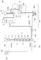
- FIG. 1 is a block diagram showing a content filling system to which a deodorizing method according to a first embodiment of the present invention is applied.
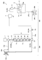
- FIG. 2 is a block diagram showing a deodorizing method according to the first embodiment of the present invention.
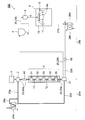
- FIG. 3 is a block diagram showing a deodorizing method according to the first embodiment of the present invention.
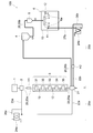
- FIG. 4 is a block diagram showing a deodorizing method according to the first embodiment of the present invention.
- FIG. 5 is a block diagram showing a deodorizing method according to the first embodiment of the present invention.
- FIG. 6 is a block diagram showing a modification of the content filling system to which the deodorizing method according to the first embodiment of the present invention is applied.
- FIG. 1 is a block diagram showing a content filling system to which a deodorizing method according to a first embodiment of the present invention is applied.
- FIG. 2 is a block diagram showing a deodorizing method according to the first embodiment of the present invention.
- FIG. 3 is
- FIG. 7 is a block diagram showing a deodorizing method according to the second embodiment of the present invention.
- FIG. 8 is a block diagram showing a deodorizing method according to the second embodiment of the present invention.
- FIG. 9 is a block diagram showing a modification of the deodorizing method according to the second embodiment of the present invention.
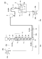
- the content filling system 100 includes a blending device 1, a balance tank 2, a heat sterilizer (product heat sterilizer) (ultra high-temperature, hereinafter referred to as UHT) 3, and a surge tank 4. And a head tank 5 and a filling device (filler) 6.
- the blending device 1, the balance tank 2, the UHT 3, the surge tank (tank) 4, the head tank (tank) 5, and the filling device 6 are arranged in this order from the upstream side to the downstream side along the beverage conveyance direction. ing.
- the preparation apparatus 1, the balance tank 2, UHT3, the surge tank 4, the head tank 5, and the filling apparatus 6 are each connected by the product supply system piping 20 which a drink passes so that it may mention later. Note that at least one of the surge tank 4 and the head tank 5 may be provided.
- the blending device 1 is for blending a product beverage at a desired blending ratio.
- the product include mineral water, carbonated drinks, tea drinks, fruit drinks, coffee drinks, milk drinks, functional drinks, alcoholic drinks, so-called energy drinks including caffeine and arginine.
- the balance tank 2 stores the beverage prepared by the preparation device 1 to facilitate the flow of the beverage.
- the heater H1 is provided in the downstream of this balance tank 2, and a chemical
- the UHT 3 heats and sterilizes the beverage supplied from the balance tank 2.
- the UHT 3 includes a first stage heating unit 31, a second stage heating unit 32, a holding tube 33, a first stage cooling unit 34, and a second stage cooling unit 35.
- the beverage supplied to the UHT 3 is gradually heated by the first stage heating unit 31 and the second stage heating unit 32 and is heated to the target temperature in the holding tube 33.
- the beverage is heated to 60 ° C. or more and 80 ° C. or less by the first stage heating unit 31 and heated to 60 ° C. or more and 150 ° C. or less by the second stage heating unit 32.
- the temperature is maintained in the holding tube 33 for a certain time.
- the beverage that has passed through the holding tube 33 is gradually cooled by the first stage cooling unit 34 and the second stage cooling unit 35. Note that the number of stages of the heating unit and the cooling unit is increased or decreased as necessary.
- the surge tank 4 stores beverage sterilized by the UHT 3.
- the head tank 5 stores a sterilized beverage to be supplied to the filling device 6.
- the filling device 6 is for filling the contents sterilized in advance from the mouth of the container 9 into the container 9.
- the empty container 9 is filled with contents.
- the contents are filled into the container 9 while the plurality of containers 9 are rotated (revolved) together with the filling nozzle 6 a.
- This content may be filled in the container 9 at room temperature.
- the contents are sterilized by heating or the like in advance, cooled to room temperature of 3 ° C. or higher and 40 ° C. or lower, and then filled in the container 9.
- the content filling system 100 has a sterile chamber 10.
- the above-described filling device 6 is accommodated in the sterile chamber 10.
- the inside of the sterilization chamber 10 is maintained in a sterilized state.
- the above-described blending device 1, balance tank 2, UHT 3, surge tank 4, head tank 5 and filling device 6 are connected to each other by a product supply system pipe 20 through which a beverage passes.
- the product supply system pipe 20 includes an upstream supply pipe 20 a located on the upstream side of the manifold valve 21 disposed between the UHT 3 and the surge tank 4, and a downstream supply pipe 20 b located on the downstream side of the manifold valve 21. Including.
- the manifold valve 21 is for switching the flow path. As shown by the thick line in FIG. 1, the manifold valve 21 causes the upstream supply pipe 20a and the downstream supply pipe 20b to communicate with each other when the container 9 is filled with a beverage.
- the manifold valve 21 communicates the upstream supply pipe 20a with an upstream return pipe 22a described later (see FIGS. 2 and 3).
- the downstream supply pipe 20b is communicated with a downstream return pipe 22b described later (see FIGS. 4 and 5).
- An upstream return pipe 22a is connected to the manifold valve 21, and a bypass pipe 23a that connects the upstream return pipe 22a and the balance tank 2 is connected to the downstream side of the upstream return pipe 22a.
- an upstream supply mechanism 24a for supplying chemicals or the like when performing CIP or the like is provided on the downstream side of the bypass piping 23a in the upstream return piping 22a.
- the upstream supply mechanism 24a is connected to an upstream introduction pipe 26a that connects the upstream supply mechanism 24a and the bypass pipe 23a, and supplies medicine and the like to the bypass pipe 23a via the upstream introduction pipe 26a. Is configured to do.
- an upstream circulation system (first circulation system) 25a for performing CIP or the like is formed by the upstream supply pipe 20a, the upstream return pipe 22a, and the bypass pipe 23a.
- a seal member made of, for example, packing is provided at each pipe, a connection portion of each member, and the like, and is configured so that beverages and the like do not leak out.
- PTFE fluororesin
- EPDM EPDM
- NBR NBR
- H-NBR silicone
- fluorine rubber packing or various rubbers covered with PTFE
- an alkaline cleaning liquid can be used as the chemical supplied to the bypass pipe 23a by the upstream supply mechanism 24a described above during CIP.
- the alkaline cleaning liquid contains a desired one of alkali components such as chlorinated alkalis such as sodium hydroxide, potassium hydroxide and sodium hypochlorite.
- alkaline cleaning liquids are composed of hydroxycarboxylic acids such as organic acids such as citric acid, succinic acid and gluconic acid, or phosphoric acid and alkanolamine salts such as alkali metal salts, alkaline earth metal salts, ammonium salts and ethylenediaminetetraacetic acid.
- Sequestering agents such as acid compounds, nonionic surfactants such as anionic surfactants, cationic surfactants, polyoxyethylene alkylphenyl ethers, solubilizers such as sodium cumene sulfonate, polyacrylic acid Or a metal salt thereof, a corrosion inhibitor, an antiseptic, an antioxidant, a dispersant, an antifoaming agent, or the like. Pure water, ion exchange water, distilled water, tap water, and the like are used as water for dissolving them.
- the alkaline cleaning liquid may contain various bleaching agents such as hypochlorite, hydrogen peroxide, peracetic acid, sodium percarbonate, thiourea dioxide and the like.
- Such an alkaline cleaning liquid may contain, for example, sodium hydroxide or potassium hydroxide in an amount of 0.1% by mass to 10% by mass.
- the alkaline cleaning liquid may contain sodium hypochlorite having a chlorine concentration of 100 to 3,000 ppm.
- the cleaning liquid containing sodium hypochlorite having a chlorine concentration of 100 to 3,000 ppm is used as the alkaline cleaning liquid, the bactericidal property can be improved as compared with the case of using the cleaning liquid containing sodium hydroxide.
- the manifold valve 21 is connected to a downstream return pipe 22b provided with a heater H2 for heating a medicine or the like at the time of CIP or the like described later.
- a downstream supply mechanism 24b is provided upstream of the downstream return pipe 22b for supplying chemicals or the like when performing CIP or the like.
- the downstream supply mechanism 24b is connected with a downstream introduction pipe 26b that connects the downstream supply mechanism 24b and the downstream return pipe 22b, and is connected to the downstream return pipe 22b via the downstream introduction pipe 26b. It is comprised so that a chemical
- the downstream return pipe 22b is connected to a drain pipe 27b that receives a medicine or the like that has passed through the filling nozzle 6a of the filling device 6 described above during CIP or the like.
- a cup 11 configured to be removable with respect to each filling nozzle 6a is attached to the drain pipe 27b.
- the cup 11 is put on the filling nozzle 6a by an actuator (not shown) when performing CIP or the like.
- the drain piping 27b is connected to the filling nozzle 6a.
- the downstream supply pipe 20b, the downstream return pipe 22b, and the drain pipe 27b form a downstream circulation system (second circulation system) 25b for performing CIP and the like.
- a seal member made of, for example, packing is provided at each pipe and each member connection portion so that beverages and the like do not leak out.
- the sealing member for example, fluororesin (PTFE), EPDM, NBR, H-NBR, silicone, fluorine rubber packing or various rubbers covered with PTFE can be used. .
- an alkaline cleaning liquid similar to the chemical supplied to the bypass pipe 23a by the upstream supply mechanism 24a is used. be able to.
- the temperature sensor 12 is connected to the upstream supply pipe 20a, the upstream return pipe 22a, the downstream supply pipe 20b, the downstream return pipe 22b, and the drain pipe 27b described above.
- the temperature sensor 12 may be disposed at a location where the temperature does not easily rise when hot water or the like is supplied therein.
- the temperature sensor 12 is disposed between the holding tube 33 of the UHT 3 and the first stage cooling unit 34.
- the temperature sensor 12 may be provided at a place other than the upstream supply pipe 20a, the upstream return pipe 22a, the downstream supply pipe 20b, the downstream return pipe 22b, and the drain pipe 27b.
- the temperature sensor 12 may be provided in a flow path through which the contents pass in the filling device 6. Information on the temperatures measured by these temperature sensors 12 is transmitted to a control device (not shown).
- the product supply system pipe 20 and the like are provided with various switching valves, pumps, and the like, which are also controlled by signals from a control device (not shown). .
- the above-described content filling system 100 may be a high-temperature filling system that fills the content at a high temperature of 85 ° C. or more and less than 100 ° C.
- the intermediate temperature filling system which fills the content under intermediate temperature 55 degreeC or more and less than 85 degreeC may be sufficient.
- FIGS. 2 to 5 pipes through which water and chemicals pass are indicated by bold lines.
- an operation button of a control device (not shown) is operated.
- the CIP is executed in a predetermined procedure (see FIGS. 2 to 5).
- the manifold valve 21 is switched, the upstream supply pipe 20a and the upstream return pipe 22a communicate (see FIGS. 2 and 3), and the downstream supply pipe 20b and the downstream return pipe 22b communicate ( FIG. 4 and FIG. 5).
- the CIP of the upstream circulation system 25a and the CIP of the downstream circulation system 25b may be performed sequentially or in parallel.
- the CIP of the upstream circulation system 25a will be described.
- water (first rinsing water for the first circulation system) is supplied to the upstream circulation system 25a.
- water is supplied into the balance tank 2 from the upstream supply mechanism 24a via the upstream introduction pipe 26a.
- the water supplied to the balance tank 2 passes through the upstream supply pipe 20a, is sent to the UHT 3, and is heated by the UHT 3.
- the water is heated to, for example, a temperature of 30 ° C. or higher and 100 ° C. or lower, for example, 50 ° C.
- the previous beverage remaining in the upstream circulation system 25a can be efficiently washed away.
- survives in the upstream circulation system 25a can be removed efficiently.
- energy saving and cost reduction can be achieved by making the temperature of water into 100 degrees C or less.
- water may be supplied into the balance tank 2 from a pipe or the like (not shown) without using the upstream supply mechanism 24a.
- the water heated by the UHT 3 passes through the manifold valve 21 through the upstream supply pipe 20a. Subsequently, the heated water is supplied to the upstream return pipe 22a, passes through the upstream return pipe 22a, and is discharged to the outside as waste liquid from the upstream supply mechanism 24a. At this time, heat exchange may be performed between the supplied water and the water discharged to the outside in the upstream supply mechanism 24a.
- the time for supplying water to the upstream circulation system 25a may be 5 minutes to 30 minutes, for example, 5 minutes.
- the time for supplying water to the upstream circulation system 25a may be 5 minutes or longer, the previous beverage remaining in the upstream circulation system 25a can be effectively washed away.
- the time for supplying water to the upstream circulation system 25a to 30 minutes or less, downtime can be shortened and energy saving can be achieved.
- a drug (first circulation system drug) is supplied to the upstream circulation system 25 a and circulated.
- the medicine is supplied from the upstream supply mechanism 24a into the balance tank 2 through the upstream introduction pipe 26a.
- an alkaline cleaning solution containing 0.1 to 10% by mass of sodium hydroxide or potassium hydroxide or an alkaline cleaning solution containing sodium hypochlorite having a chlorine concentration of 100 to 3000 ppm can be used.
- the medicine may be supplied into the balance tank 2 or the heater H1 from a pipe or the like (not shown) without using the upstream supply mechanism 24a.
- the medicine supplied to the balance tank 2 passes through the balance tank 2 and is heated by the heater H1 provided on the downstream side of the balance tank 2.
- medical agent heated by the heater H1 passes the upstream supply piping 20a, is sent to UHT3, and is further heated by UHT3.
- the drug is heated to a temperature of 70 ° C. or higher and 150 ° C. or lower, preferably 90 ° C. or higher and 145 ° C. or lower, for example, 140 ° C.
- the drug is heated to a temperature of 70 ° C. or higher and 150 ° C. or lower, preferably 90 ° C. or higher and 145 ° C. or lower, for example, 140 ° C.
- the flavor remaining in the upstream circulation system 25a can be efficiently removed.
- the upstream circulation system 25a The remaining flavor can be removed more efficiently.
- medical agent supplied to the balance tank 2 may be sent to UHT3, without being heated by the heater H1, and may be heated by UHT3.
- the heated medicine passes through the upstream supply pipe 20a and the UHT 3 and the manifold valve 21.
- the heated medicine is supplied to the upstream return pipe 22a and supplied to the bypass pipe 23a connected to the upstream return pipe 22a.
- medical agent is supplied in the balance tank 2 via the bypass piping 23a.
- the drug circulates in the upstream circulation system 25a.
- the medicine may be supplied to the heater H1 via a bypass pipe 23a by a pipe or the like (not shown) and circulate in the upstream circulation system 25a.
- the drug is circulated in the upstream circulation system 25a for a predetermined time, and then discharged from the upstream supply mechanism 24a to the outside as waste liquid (see FIG. 2).
- the time for supplying and circulating the medicine into the upstream circulation system 25a may be 5 minutes or more and 60 minutes or less, for example, 15 minutes.
- the time for supplying and circulating the medicine into the upstream circulation system 25a may be 5 minutes or longer, the flavor remaining in the upstream circulation system 25a can be effectively removed.
- the time for supplying and circulating the medicine into the first circulation system 25a is 60 minutes or less, it is possible to reduce downtime and to save energy.
- a fruit drink or the like is blended as a drink.
- beverages there are also beverages containing many flavors.
- the flavor include ethyl butyrate, ethyl 2-methylbutyrate, isoamyl acetate, limonene, ethyl caproate, isoamyl butyrate, hexyl acetate, allyl caproate, octyl aldehyde, decyl aldehyde and the like.
- representative flavors include ethyl butyrate, ethyl 2-methylbutyrate and limonene.
- the drink which does not contain flavors may be filled the next time of the drink containing many such flavors. At this time, if the flavor remains in the upstream circulation system 25a, the remaining flavor enters the next beverage, and the scent of the previous beverage adheres to the next beverage.
- a fluororesin packing is provided as a seal member at each pipe or at a connection portion of each member.
- the beverage is heated to a temperature of about 60 ° C. or more and 150 ° C. or less by the UHT 3.
- the packing provided at the connection location of each pipe may thermally expand, and a gap may be generated between each pipe and the packing.
- the flavor may enter the gap.
- the flavor that has entered the gap may be interposed between the pipes and the packing in a state of being attached to the packing.
- the flavor interposed between each piping and packing even if it supplies and circulates a chemical
- the flavor which entered into such a clearance gap may enter in the next drink from the clearance gap between each piping and packing which arises when packing is thermally expanded at the time of the filling of the next drink.
- the flavor remaining in the upstream circulation system 25a can be efficiently removed by heating the drug to a temperature of 70 ° C. or higher. That is, by heating the medicine to a temperature of 70 ° C. or higher, it is possible to cause the packing to have the same thermal expansion as that of the packing that occurs when the beverage is filled. Thereby, the flavor which entered into the gap generated when the packing thermally expands can be effectively removed. For this reason, the malfunction that the fragrance of the last drink adheres to the next drink can be suppressed. In this case, in order to obtain a higher deodorizing effect, it is effective to rinse with water at a temperature equal to or higher than the sterilization temperature of the previous product.
- each pipe and each member of the upstream circulation system 25a are connected to each other. Can be sterilized. This makes it possible to omit SIP that is normally performed after CIP. For this reason, downtime can be shortened.
- cleaning with an acidic cleaning liquid may be performed before and after purification with an alkaline cleaning liquid. Further, for example, after purification with an acidic cleaning liquid, purification with an alkaline cleaning liquid may be performed, and then further purification with an acidic cleaning liquid may be performed. Further, after purification with an alkaline cleaning liquid, purification with an acidic cleaning liquid may be performed, and then further purification with an alkaline cleaning liquid may be performed.
- water (second rinsing water for the first circulation system) is supplied to the upstream circulation system 25a.
- water is supplied to the upstream circulation system 25a.
- water is heated to, for example, a temperature of 70 ° C. or higher and 150 ° C. or lower, for example, 140 ° C. in the upstream circulation system 25a.
- the flavors described above include water-soluble flavors such as ethyl butyrate and ethyl 2-methylbutyrate.
- the water-soluble flavor remaining in the upstream circulation system 25a can be efficiently removed. For this reason, the deodorizing effect can be improved. Further, in this case, by heating the water to a temperature of 70 ° C. or higher, as described in the drug circulation step, the flavor that has entered the gap generated when the packing is thermally expanded can be removed. Moreover, energy saving can be achieved by making the temperature of water 150 degrees C or less. Even in this case, water may be supplied into the balance tank 2 from a pipe or the like (not shown) without using the upstream supply mechanism 24a.
- the time for supplying water to the upstream circulation system 25a may be 5 minutes or more and 60 minutes or less, for example, 10 minutes.
- the time for supplying water to the upstream circulation system 25a may be 5 minutes or longer, the flavor remaining in the upstream circulation system 25a can be effectively removed.
- the time for supplying water to the upstream circulation system 25a may be set to 60 minutes or less, downtime can be shortened and energy saving can be achieved.
- water (first circulatory system third rinse water) may be supplied to the upstream circulation system 25a.
- water is supplied to the upstream circulation system 25a as in the first rinsing step and the second rinsing step described above.
- the water is heated, for example, to a temperature of 30 ° C. or higher and 100 ° C. or lower, for example, 40 ° C. in the upstream circulation system 25a.
- water-soluble flavor remaining in the upstream circulation system 25a can be removed more efficiently, and the deodorizing effect can be improved.
- energy saving and cost reduction can be achieved by making the temperature of water into 100 degrees C or less. Even in this case, water may be supplied into the balance tank 2 from a pipe or the like (not shown) without using the upstream supply mechanism 24a.
- the time for supplying water to the upstream circulation system 25a may be 5 minutes or more and 120 minutes or less, for example, 10 minutes.
- the time for supplying water to the upstream circulation system 25a may be 5 minutes or longer, the flavor remaining in the upstream circulation system 25a can be more effectively removed, and the deodorizing effect can be improved.
- the time for supplying water to the upstream circulation system 25a to 120 minutes or less, downtime can be shortened and energy saving can be achieved.
- the CIP of the upstream circulation system 25a is performed, the flavor remaining in the upstream circulation system 25a is removed by the CIP, and the upstream circulation system 25a is deodorized.
- the cup 11 is placed on the filling nozzle 6a.
- the drain pipe 27b is connected to the filling nozzle 6a.
- Second circulatory system first rinse water water (second circulatory system first rinse water) is supplied to the downstream circulation system 25b.
- water is supplied from the downstream supply mechanism 24b to the downstream return pipe 22b via the downstream introduction pipe 26b.
- the water supplied to the downstream return pipe 22b is heated by the heater H2.
- the water is heated to, for example, a temperature of 40 ° C. or higher and 100 ° C. or lower, for example, 40 ° C.
- the previous beverage remaining in the downstream circulation system 25b can be efficiently washed away.
- survives in the downstream circulation system 25b can be removed efficiently.
- energy saving and cost reduction can be achieved by making the temperature of water into 100 degrees C or less.
- the heated water passes through the manifold valve 21 through the downstream return pipe 22b.
- the heated water is supplied to the downstream supply pipe 20b, passes through the downstream supply pipe 20b, the surge tank 4, the head tank 5, the filling device 6, and the drain pipe 27b, and is discharged from the downstream supply mechanism 24b as waste liquid. It is discharged outside.
- the time for supplying water to the downstream circulation system 25b may be 5 minutes or more and 30 minutes or less, for example, 5 minutes.
- the time for supplying water to the downstream circulation system 25b may be 5 minutes or more and 30 minutes or less, for example, 5 minutes.
- a medicine (second circulation system medicine) is supplied to the downstream circulation system 25b and circulated.
- the medicine is supplied from the downstream supply mechanism 24b to the downstream return pipe 22b through the downstream introduction pipe 26b.
- medical agent the alkaline washing
- the medicine supplied to the downstream return pipe 22b is heated by the heater H2.
- the drug is heated to a temperature of, for example, 70 ° C. or higher and 100 ° C. or lower, for example, 80 ° C. By heating the drug to a temperature of 70 ° C.
- the flavor remaining in the downstream circulation system 25b can be removed.
- energy saving and cost reduction can be achieved by setting the temperature of the medicine to 100 ° C. or less.
- the flavor that has entered the gap generated when the packing is thermally expanded is effectively removed. It is possible to suppress the problem that the scent of the previous beverage adheres to the next beverage.
- packing made of ethylene propylene diene rubber (EPDM) can be used. Flavor tends to adhere to the ethylene propylene diene rubber, and the flavor tends to remain in the downstream circulation system 25b.
- the flavor adhering to packing can be effectively removed by heating a chemical
- the heated medicine passes through the manifold valve 21 and passes through the downstream supply pipe 20b, the surge tank 4, the head tank 5, and the filling device 6. And it is supplied to the downstream return piping 22b via the drain piping 27b.
- the drug circulates in the downstream circulation system 25b.
- the drug is circulated in the downstream circulation system 25b for a predetermined time, and then discharged from the downstream supply mechanism 24b to the outside as waste liquid (see FIG. 4).
- the time for supplying and circulating the medicine into the downstream circulation system 25b may be 5 minutes or more and 60 minutes or less, for example, 15 minutes.
- the time for supplying and circulating the medicine into the downstream circulation system 25b By setting the time for supplying and circulating the medicine into the downstream circulation system 25b to be 5 minutes or longer, the flavor remaining in the downstream circulation system 25b can be effectively removed. In addition, by setting the time for supplying and circulating the medicine into the downstream circulation system 25b to be 60 minutes or less, it is possible to reduce downtime and to save energy.
- the cleaning with the acidic cleaning liquid may be performed before and after the purification with the alkaline cleaning liquid as in the upstream circulation system 25a. Further, for example, after purification with an acidic cleaning liquid, purification with an alkaline cleaning liquid may be performed, and then further purification with an acidic cleaning liquid may be performed. Further, after purification with an alkaline cleaning liquid, purification with an acidic cleaning liquid may be performed, and then further purification with an alkaline cleaning liquid may be performed.
- water (second rinsing water for the second circulation system) is supplied to the downstream circulation system 25b.
- water is supplied to the downstream circulation system 25b in the same manner as the first rinsing step in the downstream circulation system 25b described above.
- the water is heated to a temperature of, for example, 40 ° C. or more and 100 ° C. or less, for example, 90 ° C. in the downstream circulation system 25b.
- a temperature of 40 ° C. or higher water-soluble flavor remaining in the downstream circulation system 25b can be efficiently removed as in the upstream circulation system 25a. For this reason, the deodorizing effect can be improved.
- the surge tank 4 etc. can be handled not as the first type pressure vessel but as the second type pressure vessel by setting the temperature of the water to 100 ° C. or less, the deodorizing treatment process can be carried out at a low cost. it can.
- the time for supplying water to the downstream circulation system 25b may be 5 minutes or more and 60 minutes or less, for example, 10 minutes.
- the time for supplying water to the downstream circulation system 25b may be 5 minutes or more and 60 minutes or less, for example, 10 minutes.
- water (second circulatory system third rinse water) may be supplied to the downstream circulation system 25b after the second rinsing step in the downstream circulation system 25b described above.
- water is supplied to the downstream circulation system 25b in the same manner as the first rinse process and the second rinse process in the downstream circulation system 25b described above.
- the water is heated to a temperature of, for example, 40 ° C. or more and 100 ° C. or less, for example, 40 ° C. in the downstream circulation system 25b.
- the water-soluble flavor remaining in the downstream circulation system 25b can be removed more efficiently, and the deodorizing effect can be improved.
- energy saving can be achieved by making the temperature of water into 100 degrees C or less.
- the time for supplying water to the downstream circulation system 25b may be 5 minutes or more and 120 minutes or less, for example, 10 minutes.
- the time for supplying water to the downstream circulation system 25b may be 5 minutes or longer, the flavor remaining in the downstream circulation system 25b can be more effectively removed, and the deodorizing effect can be improved.
- the time for supplying water to the downstream circulation system 25b may be set to 120 minutes or less, downtime can be shortened and energy saving can be achieved.
- the CIP of the downstream circulation system 25b is performed, the flavor remaining in the downstream circulation system 25b is removed by the CIP, and the downstream circulation system 25b is deodorized.
- Deodorization confirmation process Moreover, you may provide the deodorizing confirmation process whether the deodorizing effect was enough.
- the deodorization confirmation process first, water is sent to the content filling system 100. At this time, the water is fed in a state where the temperature at the outlet of the UHT 3 is lowered from about 80 ° C. to about 90 ° C. from the temperature at the second rinsing step in the upstream circulation system 25a (eg, 140 ° C.). And it can carry out by sampling water from the drain piping 27b of the exit of the filling apparatus 6, and confirming whether the smell is removed. At this time, a sensor that can distinguish odors may be provided. Further, the container 6 may be filled with water by the filling device 6 to check the odor. And when a result is NG in this deodorization confirmation process, CIP is performed again. Note that the deodorization confirmation step may be performed individually in the upstream circulation system 25a and the downstream circulation system 25b.
- the drug in the drug circulation step in the upstream circulation system 25a, the drug is heated to a temperature of 70 ° C. or higher in the upstream circulation system 25a.
- the temperature of the medicine is 150 ° C. or lower in the upstream circulation system 25a.
- energy saving can be achieved.
- the time for supplying and circulating the drug in the upstream circulation system 25a or the downstream circulation system 25b is 5 minutes or more. Thereby, the flavor remaining in the upstream circulation system 25a or the downstream circulation system 25b can be effectively removed.
- the time for supplying and circulating the medicine in the upstream circulation system 25a or the downstream circulation system 25b is 60 minutes or less. Thereby, downtime can be shortened and energy saving can be achieved.
- water in the second rinsing step, water is heated to a temperature of 70 ° C. or higher in the upstream circulation system 25a. Further, the water is heated to a temperature of 40 ° C. or higher in the downstream circulation system 25b. Thereby, the water-soluble flavor remaining in the upstream circulation system 25a or the downstream circulation system 25b can be efficiently removed. Moreover, the temperature of water is 150 degrees C or less in the upstream circulation system 25a. Moreover, the temperature of water is 100 degrees C or less in the downstream side circulation system 25b. Thereby, energy saving can be achieved. The fact that the water-soluble flavor remaining in the upstream circulation system 25a can be efficiently removed as described above will be described with reference to examples described later.
- the time for supplying water to the upstream circulation system 25a or the downstream circulation system 25b is 5 minutes or more. Thereby, the flavor remaining in the upstream circulation system 25a or the downstream circulation system 25b can be effectively removed.
- the time for supplying water to the upstream circulation system 25a or the downstream circulation system 25b is 60 minutes or less. Thereby, downtime can be shortened and energy saving can be achieved.
- the example in which the drug is heated to a temperature of 70 ° C. or more and 100 ° C. or less in the drug circulation step in the downstream circulation system 25b has been described. That is, in the above-described embodiment, assuming that the surge tank 4 or the like of the downstream circulation system 25b is handled as the second type pressure vessel, the example in which the medicine is heated to a temperature of 70 ° C. or higher and 100 ° C. or lower. explained. On the other hand, when the surge tank 4 or the like of the downstream circulation system 25b is handled as a first type pressure vessel, the chemical is, for example, at a temperature of 70 ° C. or higher and 150 ° C. or lower, for example, 130 ° C. It may be heated.
- the flavor remaining in the downstream circulation system 25b can be efficiently removed by heating the drug to a temperature of 70 ° C. or higher, and energy saving can be achieved by setting the temperature of the drug to 150 ° C. or lower. Can be planned.
- the flavor remaining in the downstream circulation system 25b can be more efficiently removed by heating the medicine to a high temperature of 130 ° C. as an example.
- the manifold valve 21 is provided in the content filling system 100 .
- the present invention is not limited to this.
- the CIP from the UHT 3 to the filling device 6 may be performed simultaneously without providing the manifold valve 21.
- the content filling system 100 may further include a carbonic acid line 40 provided with a carbonic acid addition device 41 for adding carbonic acid to the beverage.
- the carbonic acid line 40 is connected to the downstream supply pipe 20b through a manifold valve 21b provided between the surge tank 4 and the head tank 5.
- the beverage passes through the downstream supply pipe 20 b and is supplied to the carbonic acid line 40, and carbonic acid is added by the carbonic acid addition device 41.
- the beverage to which carbonic acid has been added passes through the manifold valve 21 b from the carbonic acid line 40 and is supplied to the downstream supply pipe 20 b and the head tank 5, and is filled into the container 9 by the filling device 6.
- the above-described manifold valve 21b may be provided on the downstream side of the head tank 5.
- the heating device for heating water may be, for example, an aseptic water sterilization device used in an aseptic filling machine for bottle rinsing, cap rinsing, etc., or another product heating sterilizer.
- the UHT 3 may be an injection method or an infusion method, and a heat exchanger used for heat exchange in the content filling system 100 such as a heat exchanger of the UHT 3 may be a plate type or a shell and tube type.
- FIGS. 2 to 5, 7 and 8. 7 and 8 the same parts as those in the first embodiment are denoted by the same reference numerals, and detailed description thereof is omitted.
- FIG. 7 and FIG. 8 pipes through which water, chemicals and steam pass are indicated by bold lines.
- the pipe indicated by the thick line may pass through the steam.
- an operation button of a control device (not shown) is operated.
- CIP and SIP are respectively executed in a predetermined procedure (see FIGS. 2 to 5).
- the manifold valve 21 is switched, the upstream supply pipe 20a and the upstream return pipe 22a communicate (see FIGS. 2 and 3), and the downstream supply pipe 20b and the downstream return pipe 22b communicate ( FIG. 4 and FIG. 5).
- the CIP and SIP of the upstream circulation system 25a and the CIP and SIP of the downstream circulation system 25b may be performed sequentially or in parallel.
- the CIP process (first CIP process) and the SIP process (first SIP process) of the upstream circulation system 25a will be described.
- the water supplied to the upstream circulation system 25a passes through the manifold valve 21 through the upstream supply pipe 20a. Subsequently, the water is supplied to the upstream return pipe 22a, passes through the upstream return pipe 22a, and is discharged to the outside as waste liquid from the upstream supply mechanism 24a. At this time, heat exchange may be performed between the supplied water and the water discharged to the outside in the upstream supply mechanism 24a.
- the time for supplying water to the upstream circulation system 25a may be 5 minutes to 30 minutes, for example, 5 minutes.
- the medicine is supplied to the upstream circulation system 25a and circulated.
- the medicine is supplied from the upstream supply mechanism 24a into the balance tank 2 through the upstream introduction pipe 26a.
- an alkaline cleaning solution containing 0.1 to 10% by mass of sodium hydroxide or potassium hydroxide or an alkaline cleaning solution containing sodium hypochlorite having a chlorine concentration of 100 to 3000 ppm can be used.
- the medicine may be supplied into the balance tank 2 or the heater H1 from a pipe or the like (not shown) without using the upstream supply mechanism 24a.
- the medicine supplied to the balance tank 2 passes through the balance tank 2 and is heated by the heater H1 provided on the downstream side of the balance tank 2. Moreover, the chemical
- the heated medicine passes through the upstream supply pipe 20a and the UHT 3 and the manifold valve 21. Subsequently, the heated medicine is supplied to the upstream return pipe 22a and supplied to the bypass pipe 23a connected to the upstream return pipe 22a. And a chemical
- medical agent is supplied in the balance tank 2 via the bypass piping 23a. In this way, the drug circulates in the upstream circulation system 25a.
- the medicine may be supplied to the heater H1 via a bypass pipe 23a by a pipe or the like (not shown) and circulate in the upstream circulation system 25a. Thereafter, the drug is circulated in the upstream circulation system 25a for a predetermined time, and then discharged from the upstream supply mechanism 24a to the outside as waste liquid (see FIG. 2).
- the time for supplying and circulating the medicine into the upstream circulation system 25a may be 5 minutes or more and 60 minutes or less, for example, 15 minutes.
- cleaning with an acidic cleaning liquid may be performed before and after purification with an alkaline cleaning liquid. Further, for example, after purification with an acidic cleaning liquid, purification with an alkaline cleaning liquid may be performed, and then further purification with an acidic cleaning liquid may be performed. Further, after purification with an alkaline cleaning liquid, purification with an acidic cleaning liquid may be performed, and then further purification with an alkaline cleaning liquid may be performed.
- water is supplied to the upstream circulation system 25a.
- water is supplied to the upstream circulation system 25a.
- water is supplied to the upstream circulation system 25a at a temperature of 10 ° C. or higher and 40 ° C. or lower, for example, 15 ° C. as an example.
- the time for supplying water to the upstream circulation system 25a may be 5 minutes or more and 60 minutes or less, for example, 10 minutes. Even in this case, water may be supplied into the balance tank 2 from a pipe or the like (not shown) without using the upstream supply mechanism 24a.
- water may be supplied to the upstream circulation system 25a after the second rinsing step described above.
- water is supplied to the upstream circulation system 25a as in the first rinsing step and the second rinsing step described above.
- water is supplied to the upstream circulation system 25a in the upstream circulation system 25a, for example, at a temperature of 10 ° C. or more and 40 ° C. or less, for example, 15 ° C.
- the time for supplying water to the upstream circulation system 25a may be 5 minutes or more and 60 minutes or less, for example, 10 minutes. Even in this case, water may be supplied into the balance tank 2 from a pipe or the like (not shown) without using the upstream supply mechanism 24a.
- the SIP of the upstream circulation system 25a is performed.
- the water heated by the UHT 3 passes through the manifold valve 21 through the upstream supply pipe 20a. Subsequently, the heated water is supplied to the upstream return pipe 22a and supplied to the bypass pipe 23a connected to the upstream return pipe 22a. And water is supplied in the balance tank 2 via the bypass piping 23a. In this way, water circulates in the upstream circulation system 25a.
- the water may be supplied to the heater H1 via a bypass pipe 23a by a pipe (not shown) or the like and circulate in the upstream circulation system 25a. Thereafter, the water is circulated in the upstream circulation system 25a for a predetermined time, and then discharged to the outside as waste liquid from the upstream supply mechanism 24a (see FIG. 2).
- the water when water is supplied to the upstream circulation system 25a for circulation, the water is supplied to the upstream circulation system 25a and the circulation time is 5 minutes or more and 60 minutes or less, for example, 5 minutes. good.
- the working fluid for sterilization such as steam or the above-described chemicals may be supplied to the upstream circulation system 25a.
- the UHT 3 heated for SIP is cooled to a desired set temperature.
- the supplied water passes through the manifold valve 21 through the downstream return pipe 22b.
- water is supplied to the downstream supply pipe 20b, passes through the downstream supply pipe 20b, the surge tank 4, the head tank 5, the filling device 6, and the drain pipe 27b, and is discharged to the outside as waste liquid from the downstream supply mechanism 24b. Is done.
- the time for supplying water to the downstream circulation system 25b may be 5 minutes or more and 30 minutes or less, for example, 5 minutes.
- the medicine is supplied to the downstream circulation system 25b and circulated.
- the medicine is supplied from the downstream supply mechanism 24b to the downstream return pipe 22b through the downstream introduction pipe 26b.
- cleaning liquid similar to the chemical
- the medicine supplied to the downstream return pipe 22b is heated by the heater H2.
- the drug is heated to a temperature of, for example, 70 ° C. or higher and 150 ° C. or lower, for example, 80 ° C.
- the heated medicine passes through the manifold valve 21 and passes through the downstream supply pipe 20b, the surge tank 4, the head tank 5, and the filling device 6. And it is supplied to the downstream return piping 22b via the drain piping 27b.
- the drug circulates in the downstream circulation system 25b.
- the drug is circulated in the downstream circulation system 25b for a predetermined time, and then discharged from the downstream supply mechanism 24b to the outside as waste liquid (see FIG. 4).
- the time for supplying and circulating the medicine into the downstream circulation system 25b may be 5 minutes or more and 60 minutes or less, for example, 15 minutes.
- the cleaning with the acidic cleaning liquid may be performed before and after the purification with the alkaline cleaning liquid as in the upstream circulation system 25a. Further, for example, after purification with an acidic cleaning liquid, purification with an alkaline cleaning liquid may be performed, and then further purification with an acidic cleaning liquid may be performed. Further, after purification with an alkaline cleaning liquid, purification with an acidic cleaning liquid may be performed, and then further purification with an alkaline cleaning liquid may be performed.
- water is supplied to the downstream circulation system 25b.
- water is supplied to the downstream circulation system 25b in the same manner as the first rinsing step in the downstream circulation system 25b described above.
- water is supplied to the downstream circulation system 25b in the downstream circulation system 25b, for example, at a temperature of 10 ° C. or more and 40 ° C. or less, for example, 15 ° C.
- the time for supplying water to the downstream circulation system 25b may be 5 minutes or more and 60 minutes or less, for example, 10 minutes.
- water may be supplied to the downstream circulation system 25b after the second rinsing step in the downstream circulation system 25b described above.
- water is supplied to the downstream circulation system 25b in the same manner as the first rinse process and the second rinse process in the downstream circulation system 25b described above.
- water is supplied to the downstream circulation system 25b in the downstream circulation system 25b, for example, at a temperature of 10 ° C. or more and 40 ° C. or less, for example, 15 ° C.
- the time for supplying water to the downstream circulation system 25b may be 5 minutes or more and 120 minutes or less, for example, 10 minutes.
- the SIP of the downstream circulation system 25b is performed.
- steam is supplied to the downstream circulation system 25b.
- steam is supplied from the manifold valve 21.
- the steam is supplied to the downstream circulation system 25b at, for example, a temperature of 90 ° C. or higher and 150 ° C. or lower, for example, 135 ° C.
- the steam may be supplied from the upper part of the tanks 4 and 5.
- the steam supplied to the manifold valve 21 is discharged to the outside through the downstream supply pipe 20b, the surge tank 4, the head tank 5, the filling device 6, and the drain pipe 27b.
- the time for supplying the steam to the downstream circulation system 25b may be 5 minutes or more and 60 minutes or less, for example, 5 minutes.
- the downstream circulation system 25b is cooled with aseptic air.
- aseptic air is sent into the downstream supply pipe 20b, and the downstream supply pipe 20b, the surge tank 4, the filling device 6 and the like are cooled.
- cooling with aseptic air is performed until the temperature of the flow path through which the contents pass in the filling device 6 becomes 60 ° C. or more and 100 ° C. or less.
- the downstream circulation system 25b may be cooled by supplying sterile water to the downstream circulation system 25b.
- an operation button of a control device (not shown) is operated. Thereby, the manifold valve 21 is switched, and the upstream supply pipe 20a and the downstream supply pipe 20b communicate with each other (see FIG. 8).
- water is supplied to the upstream circulation system 25a where SIP has been performed.
- water is supplied into the balance tank 2 from the upstream supply mechanism 24a via the upstream introduction pipe 26a.
- the water supplied to the balance tank 2 is sent to the UHT 3 through the upstream supply pipe 20a. Even in this case, water may be supplied into the balance tank 2 from a pipe or the like (not shown) without using the upstream supply mechanism 24a.
- the water supplied to the upstream circulation system 25a is sterilized by heating with UHT3.
- the content filling system 100 can be deodorized while maintaining sterility by heating and sterilizing the supplied water with the UHT 3.
- the temperature at the outlet of the UHT 3 is, for example, a temperature of 70 ° C. or higher and 100 ° C. or lower, for example, 90 ° It is heated to become.
- each tank 4, 5 etc. can be handled not as a 1st type pressure vessel but a 2nd type pressure vessel by making the temperature of water into 90 degrees C or less, a deodorizing process process is implemented at low cost. be able to.
- the tanks 4, 5, etc. may be changed to first type pressure vessels and deodorized with water at 100 ° C. or higher. In this case, when draining water out of the circulation systems 25a and 25b, the temperature may be lowered to less than 100 ° C. and then drained.
- the time for supplying water to the upstream circulation system 25a may be 5 minutes or more and 120 minutes or less, for example, 30 minutes.
- the time for supplying water to the upstream circulation system 25a may be 5 minutes or longer, the flavor remaining in the upstream circulation system 25a can be effectively removed.
- the time for supplying water to the upstream circulation system 25a to 120 minutes or less, downtime can be shortened and energy saving can be achieved.
- water heated by the UHT 3 is supplied to the downstream circulation system 25b where SIP has been performed.
- the water heated by the UHT 3 passes through the manifold valve 21 through the upstream supply pipe 20a. Then, it is supplied to the downstream supply pipe 20b.
- the water supplied to the downstream supply pipe 20b passes through the surge tank 4, the head tank 5, the filling device 6, and the drain pipe 27b, and is discharged to the outside from the downstream supply mechanism 24b as waste liquid.
- the drain pipe 27 b may be removed from the filling nozzle 6 a and the water may be discharged into the aseptic chamber 10. In this case, water is discharged to the outside as waste liquid from a discharge pipe (not shown) connected to the sterilization chamber 10.
- the time for supplying the water to the downstream circulation system 25b is 5 minutes or more and 120 minutes or less, for example, 30 minutes. good.
- the time for supplying water to the downstream circulation system 25b is 5 minutes or more and 120 minutes or less, for example, 30 minutes. good.
- Deodorization confirmation process Moreover, you may provide the deodorizing confirmation process whether the deodorizing effect was enough.
- the deodorization confirmation process first, water is sent to the content filling system 100. At this time, the water is fed in a state where the temperature at the outlet of the UHT 3 is lowered from 30 ° C. to 40 ° C. from the temperature during the deodorization process (for example, 90 ° C.). And it can carry out by sampling water from the drain piping 27b of the exit of the filling apparatus 6, and confirming whether the smell is removed. At this time, a sensor that can distinguish odors may be provided. Further, the container 6 may be filled with water by the filling device 6 to check the odor. And when a result is NG in this deodorization confirmation process, a deodorization process process is performed again.
- a fruit drink or the like is blended as a drink.
- beverages there are also beverages containing many flavors.
- the flavor remains in the upstream circulation system 25a and the downstream circulation system 25b, the remaining flavor enters the next beverage, and the scent of the previous beverage adheres to the next beverage. There is.
- a fluororesin packing is provided as a seal member at each pipe or at a connection portion of each member.
- ethylene propylene diene rubber (EPDM) packing is provided as a sealing member at each pipe, a connection portion of each member, and the like.
- EPDM ethylene propylene diene rubber
- the flavor may enter the gap.
- the flavor that has entered the gap may be interposed between the pipes and the packing in a state of being attached to the packing.
- the flavor which entered into such a clearance gap may enter in the next drink from the clearance gap between each piping and packing which arises when packing is thermally expanded at the time of the filling of the next drink.
- the water remaining at the upstream circulation system 25a and the downstream circulation system 25b is made efficient by heating water to a temperature of 60 ° C. or higher and 150 ° C. or lower. Can be removed well. That is, by heating water to a temperature of 60 ° C. or higher and 150 ° C. or lower, the amount of thermal expansion generated in the packing can be brought close to the amount of thermal expansion of the packing generated when filling the beverage. Thereby, the flavor which entered into the gap generated when the packing thermally expands can be effectively removed. For this reason, the malfunction that the fragrance of the last drink adheres to the next drink can be suppressed.
- packing made of ethylene propylene diene rubber can be used.
- Flavor tends to adhere to the ethylene propylene diene rubber, and the flavor tends to remain in the downstream circulation system 25b.
- the flavor adhering to the packing can be effectively removed by heating the water to a temperature of 60 ° C. or higher and 150 ° C. or lower. In this case, in order to obtain a higher deodorizing effect, it is effective to rinse with water at a temperature equal to or higher than the sterilization temperature of the previous product.
- the flavors described above include water-soluble flavors such as ethyl butyrate and ethyl 2-methylbutyrate.
- the water-soluble flavor remaining in the upstream circulation system 25a and the downstream circulation system 25b can be efficiently removed by heating the water to a temperature of 60 ° C. or more and 150 ° C. or less. For this reason, the deodorizing effect can be improved.
- the deodorizing treatment step is a step of supplying water to the upstream circulation system 25a where SIP is performed, and the water supplied to the upstream circulation system 25a is heated by the UHT 3. And a step of supplying water heated by the UHT 3 to the downstream circulation system 25b where the SIP is performed.
- the upstream side is maintained in a sterile state. The flavor remaining in the circulation system 25a and the downstream circulation system 25b can be removed.
- water is heated to a temperature of 70 ° C. or higher.
- the flavor remaining in the upstream circulation system 25a and the downstream circulation system 25b, in particular, the water-soluble flavor can be efficiently removed.
- the temperature of water is 100 degrees C or less. Thereby, energy saving and cost reduction can be achieved.
- the time for supplying water to the upstream circulation system 25a is 5 minutes or more. Thereby, the flavor remaining in the upstream circulation system 25a can be effectively removed.
- the time for supplying water to the upstream circulation system 25a is 120 minutes or less. Thereby, downtime can be shortened and energy saving can be achieved.
- the time for supplying the water heated by the UHT 3 to the downstream circulation system 25b is 5 minutes or more. Thereby, the flavor remaining in the downstream circulation system 25b can be effectively removed.
- the time for supplying water to the downstream circulation system 25b is 120 minutes or less. Thereby, downtime can be shortened and energy saving can be achieved.
- aseptic air is maintained until the temperature of the flow path through which the contents pass in the filling device 6 becomes 60 ° C. or higher and 100 ° C. or lower.
- the present invention is not limited to this.
- the temperature of the flow path through which the contents pass in the filling device 6 of the downstream circulation system 25b is cooled to a temperature of 80 ° C. or higher and 100 ° C. or lower with aseptic air
- the water heated by the UHT 3 is supplied upstream. It is preferable to supply the circulation system 25a to the downstream circulation system 25b.
- the temperature of the filling device 6 after cooling with aseptic air is 80 ° C.
- the present invention is not limited to this.
- the drug in the CIP drug circulation step, the drug is heated to a temperature of 70 ° C. or higher, and the time for supplying and circulating the drug in the upstream circulation system 25a and the downstream circulation system 25b is 5 minutes or more.
- the pipes and members of the upstream circulation system 25a and the downstream circulation system 25b may be sterilized. This makes it possible to omit SIP that is normally performed after CIP. For this reason, downtime can be shortened.
- the downstream circulation system 25 b is connected to the downstream side of the surge tank 4, and produces a sterilized water heat sterilizer (heat sterilizer for producing sterile water) (hereinafter referred to as UHT).
- UHT sterilized water heat sterilizer
- water may be supplied to the UHT 3b and heated, and the water heated by the UHT 3b may be supplied to the downstream circulation system 25b after SIP is performed.
- the water heated by the UHT 3b passes through the sterile water supply pipe 28b and passes through the manifold valve 21b. Subsequently, after circulating through the carbonic acid line 40, it passes through the manifold valve 21b and is supplied to the downstream supply pipe 20b. The water heated by the UHT 3b may be directly sent to the filling device 6 without passing through the carbonic acid line.
- the water supplied to the downstream supply pipe 20b passes through the head tank 5, the filling device 6, and the drain pipe 27b, and is discharged to the outside as a waste liquid from the downstream supply mechanism 24b.
- the drain pipe 27 b may be removed from the filling nozzle 6 a and the water may be discharged into the aseptic chamber 10. In this case, water is discharged to the outside as waste liquid from a discharge pipe (not shown) connected to the sterilization chamber 10.
- the water may be heated so that the temperature at the outlet of the UHT 3b is 70 ° C. or higher and 100 ° C. or lower, for example, 90 ° C.
- the temperature at the outlet of the UHT 3b is 70 ° C. or higher and 100 ° C. or lower, for example, 90 ° C.
- the deodorizing effect can be improved.
- the head tank 5 etc. can be handled not as a first type pressure vessel but as a second type pressure vessel by setting the water temperature to 90 ° C. or lower, the deodorizing treatment process can be carried out at a low cost. it can.
- the time for supplying water to the downstream circulation system 25b may be 5 minutes or more and 120 minutes or less, for example, 30 minutes.
- the time for supplying water to the downstream circulation system 25b may be 5 minutes or more and 120 minutes or less, for example, 30 minutes.
- the downstream circulation system 25b includes the UHT 3b connected to the downstream side of the surge tank 4, and in the deodorizing process, water is supplied to the UHT 3b and heated, so that SIP is performed. Water heated by the UHT 3b is supplied to the downstream circulation system 25b after being broken. As a result, as shown by the thick line in FIG. 9, during the deodorizing process of the downstream circulation system 25 b, the next product is prepared in the upstream circulation system 25 a where the SIP has been completed, and the surge tank 4 It can also be stored. Thereby, downtime can be reduced significantly.
- the above-described manifold valve 21b is preferably provided on the downstream side of the head tank. is there.
- the heating device for heating water may be, for example, an aseptic water sterilization device used in an aseptic filling machine for bottle rinsing, cap rinsing or the like, or other product heating sterilizer.
- the UHT 3b may be an injection method or an infusion method, like the UHT 3.
- the supply temperature of the fruit drink is 20 ° C.
- the temperature of the fruit drink heated by the holding tube 33 of the UHT 3 is 115 ° C.
- the temperature of the fruit drink that has passed through the second stage cooling unit 35 is 30 ° C. there were.
- the fruit drink was discharged to the outside from the upstream supply mechanism 24a, and the upstream circulation system 25a was CIPed.
- the upstream circulation system 25a was CIPed.
- 15 ° C. water was supplied to the upstream circulation system 25a for 5 minutes.
- the drug was supplied to the upstream circulation system 25a and circulated.
- the time for supplying and circulating the medicine to the upstream circulation system 25a was 15 minutes.
- an alkaline cleaning solution containing 2% by mass of sodium hydroxide was used as a drug.
- the temperature of the drug heated by the holding tube 33 of UHT3 was 140 ° C.
- Table 1 shows the contents of ethyl butyrate, 2-methylbutyrate contained in the sample data obtained in the example with respect to the contents of ethyl butyrate, ethyl 2-methylbutyrate and limonene contained in the sample data obtained in the comparative example.
- the ratio of ethyl butyrate and limonene content is shown.
- the content of ethyl butyrate contained in the rinse water could be 19% relative to the comparative example.
- the content of ethyl 2-methylbutyrate contained in the rinse water could be 33% of the comparative example.
- the content of limonene contained in the rinse water could be 75% of the comparative example.
- the flavor remaining in the upstream circulation system 25a can be efficiently removed.
- the water-soluble flavor remaining in the upstream circulation system 25a can be efficiently removed by heating the water to a temperature of 140 ° C.
Abstract
Provided is a deodorization method including: a first rinsing step of supplying a first rinse water for a first circulation system to a first circulation system (25a) including at least a heat sterilizer (3) for heating a beverage; a reactant circulation step of supplying and circulating a reactant for the first circulation system to the first circulation system (25a); and a second rinsing step of supplying a second rinse water for the first circulation system to the first circulation system (25a). In the reactant circulation step, the reactant for the first circulation system is heated to a temperature of 70°C-150°C in the first circulation system (25a).
Description
本発明は、内容物充填システムを脱臭する脱臭方法に関する。
The present invention relates to a deodorizing method for deodorizing a content filling system.
従来から、飲料をボトル等の容器に充填するシステムとして、飲料自体を殺菌するとともに、サージタンク、配管、充填ノズル等を殺菌して無菌状態にする内容物充填システムが知られている。このような内容物充填システムでは、例えば飲料の種類を切り替える際に、CIP(Cleaning in Place)処理をし、さらに、SIP(Sterilizing in Place)処理をしている(例えば、特許文献1)。
Conventionally, as a system for filling a beverage such as a bottle, a content filling system for sterilizing the beverage itself and sterilizing the surge tank, the piping, the filling nozzle, etc. is known. In such a content filling system, for example, when a beverage type is switched, a CIP (Cleaning in Place) process is performed, and a SIP (Sterilizing in Place) process is performed (for example, Patent Document 1).
CIPは、飲料の流路やタンクに付着した前回の飲料の残留物等を除去するためのものであり、飲料の流路に、例えば水に苛性ソーダ等のアルカリ性薬剤を添加した洗浄液を流した後に、水に酸性薬剤を添加した洗浄液を流すことにより行われる。
CIP is for removing the residue of the previous drink adhering to the flow path and tank of a drink, and after flowing the washing liquid which added alkaline chemicals, such as caustic soda, to the flow path of a drink. It is performed by flowing a cleaning liquid obtained by adding an acidic chemical to water.
SIPは、飲料の流路やタンクを殺菌処理し、無菌状態にするためのものであり、例えば、CIPで洗浄した流路内に加熱蒸気または熱水を流すことによって行われる。
SIP is for sterilizing beverage flow paths and tanks to make them sterile, and is performed, for example, by flowing heated steam or hot water into the flow paths cleaned with CIP.
しかしながら、近年、このような内容物充填システムでは、例えばミネラルウォーター、炭酸飲料、茶系飲料、果実飲料、コーヒー飲料、乳飲料、機能性飲料、アルコール入り飲料、カフェインやアルギニンを含むいわゆるエナジードリンク等の多様な飲料が充填されるようになっている。また、このような多様な飲料には、多くのフレーバーが含有している飲料も存在する。さらに、フレーバーを多く含有する飲料の次回に、例えばミネラルウォーター等のフレーバーを含まない飲料を充填する場合もある。このため、CIPおよびSIP後に、飲料の流路にフレーバーが残存していた場合、残存するフレーバーが次回の飲料に入り込み、前回の飲料の香りが次回の飲料に付着してしまう問題がある。前回の飲料の香りが次回の飲料に付着していた場合、再度CIPおよびSIPを行う必要があり、生産性が著しく悪化する。
However, in recent years, in such a content filling system, for example, mineral water, carbonated drinks, tea-based drinks, fruit drinks, coffee drinks, milk drinks, functional drinks, alcoholic drinks, so-called energy drinks including caffeine and arginine Various drinks such as these are filled. In addition, such a variety of beverages include beverages containing many flavors. Furthermore, the drink which does not contain flavors, such as mineral water, for example may be filled the next time of the drink containing many flavors. For this reason, when the flavor remains in the flow path of the beverage after CIP and SIP, there is a problem that the remaining flavor enters the next beverage, and the scent of the previous beverage adheres to the next beverage. When the scent of the previous beverage is attached to the next beverage, it is necessary to perform CIP and SIP again, and the productivity is significantly deteriorated.
本発明はこのような点を考慮してなされたものであり、内容物充填システムに残存するフレーバーを効率良く除去することが可能な脱臭方法を提供することを目的とする。
The present invention has been made in consideration of such points, and an object thereof is to provide a deodorizing method capable of efficiently removing the flavor remaining in the content filling system.
本発明は、CIPにより内容物充填システムを脱臭する脱臭方法において、飲料を加熱する加熱殺菌機を少なくとも含む第1循環系に、第1循環系用第1すすぎ水を供給する第1すすぎ工程と、前記第1循環系に第1循環系用薬剤を供給して循環させる薬剤循環工程と、前記第1循環系に第1循環系用第2すすぎ水を供給する第2すすぎ工程とを備え、前記薬剤循環工程において、前記第1循環系用薬剤は、前記第1循環系内において、70℃以上150℃以下の温度に加熱される、脱臭方法である。
The present invention relates to a deodorizing method for deodorizing a content filling system by CIP, a first rinsing step of supplying first rinsing water for the first circulation system to a first circulation system including at least a heat sterilizer for heating a beverage; A drug circulation step of supplying and circulating a first circulation system drug to the first circulation system, and a second rinse step of supplying a first circulation system second rinse water to the first circulation system, In the drug circulation step, the first circulation system drug is a deodorization method in which the first circulation system is heated to a temperature of 70 ° C. or more and 150 ° C. or less in the first circulation system.
本発明は、前記薬剤循環工程において、前記第1循環系用薬剤を前記第1循環系内に供給して循環させる時間は、5分以上60分以下である、脱臭方法である。
The present invention is the deodorization method in which, in the drug circulation step, the time for supplying and circulating the first circulation system drug in the first circulation system is 5 minutes or more and 60 minutes or less.
本発明は、前記第2すすぎ工程において、前記第1循環系用第2すすぎ水は、前記第1循環系内において、70℃以上150℃以下の温度に加熱される、脱臭方法である。
The present invention is a deodorization method in which, in the second rinsing step, the second rinsing water for the first circulation system is heated to a temperature of 70 ° C. or more and 150 ° C. or less in the first circulation system.
本発明は、前記第2すすぎ工程において、前記第1循環系用第2すすぎ水を前記第1循環系に供給する時間は、5分以上60分以下である、脱臭方法である。
The present invention is the deodorization method in which, in the second rinsing step, the time for supplying the second rinsing water for the first circulation system to the first circulation system is 5 minutes or more and 60 minutes or less.
本発明は、前記第1すすぎ工程において、前記第1循環系用第1すすぎ水は、前記第1循環系内において、30℃以上100℃以下の温度に加熱される、脱臭方法である。
The present invention is a deodorization method in which, in the first rinsing step, the first rinsing water for the first circulation system is heated to a temperature of 30 ° C. or more and 100 ° C. or less in the first circulation system.
本発明は、前記第1すすぎ工程において、前記第1循環系用第1すすぎ水を前記第1循環系に供給する時間は、5分以上30分以下である、脱臭方法である。
The present invention is the deodorization method in which, in the first rinsing step, the time for supplying the first rinsing water for the first circulation system to the first circulation system is 5 minutes or more and 30 minutes or less.
本発明は、前記第1循環系に第1循環系用第3すすぎ水を供給する第3すすぎ工程を更に備え、前記第3すすぎ工程において、前記第1循環系用第3すすぎ水は、前記第1循環系内において、30℃以上100℃以下の温度に加熱される、脱臭方法である。
The present invention further includes a third rinsing step of supplying a first circulatory system third rinse water to the first circulatory system, wherein in the third rinsing step, the first circulatory system third rinse water is In the first circulation system, the deodorization method is performed at a temperature of 30 ° C. or higher and 100 ° C. or lower.
本発明は、前記第3すすぎ工程において、前記第1循環系用第3すすぎ水を前記第1循環系に供給する時間は、5分以上120分以下である、脱臭方法である。
The present invention is the deodorization method in which, in the third rinsing step, the time for supplying the third rinsing water for the first circulation system to the first circulation system is 5 minutes or more and 120 minutes or less.
本発明は、CIPにより内容物充填システムを脱臭する脱臭方法において、容器に内容物を充填する充填装置を少なくとも含む第2循環系に、第2循環系用第1すすぎ水を供給する第1すすぎ工程と、前記第2循環系に第2循環系用薬剤を供給して循環させる薬剤循環工程と、前記第2循環系に第2循環系用第2すすぎ水を供給する第2すすぎ工程とを備え、前記第2すすぎ工程において、前記第2循環系用第2すすぎ水は、前記第2循環系内において、40℃以上100℃以下の温度に加熱される、脱臭方法である。
The present invention relates to a deodorization method for deodorizing a content filling system by CIP, wherein a first rinsing water for a second circulation system is supplied to a second circulation system including at least a filling device for filling a container with the contents. A step of supplying a second circulatory system drug to the second circulatory system for circulation, and a second rinse step of supplying the second circulatory system second rinse water to the second circulatory system. In the second rinsing step, the second rinsing water for the second circulation system is heated to a temperature of 40 ° C. or more and 100 ° C. or less in the second circulation system.
本発明は、前記第2すすぎ工程において、前記第2循環系用第2すすぎ水を前記第2循環系に供給する時間は、5分以上60分以下である、脱臭方法である。
The present invention is the deodorization method in which, in the second rinsing step, the time for supplying the second rinsing water for the second circulation system to the second circulation system is 5 minutes or more and 60 minutes or less.
本発明は、前記第1すすぎ工程において、前記第2循環系用第1すすぎ水は、前記第2循環系内において、40℃以上100℃以下の温度に加熱される、脱臭方法である。
The present invention is the deodorization method in which, in the first rinsing step, the first rinsing water for the second circulation system is heated to a temperature of 40 ° C. or more and 100 ° C. or less in the second circulation system.
本発明は、前記第1すすぎ工程において、前記第2循環系用第1すすぎ水を前記第2循環系に供給する時間は、5分以上30分以下である、脱臭方法である。
The present invention is a deodorization method in which, in the first rinsing step, the time for supplying the first rinsing water for the second circulation system to the second circulation system is 5 minutes or more and 30 minutes or less.
本発明は、前記第2循環系に第2循環系用第3すすぎ水を供給する第3すすぎ工程を更に備え、前記第3すすぎ工程において、前記第2循環系用第3すすぎ水は、前記第2循環系内において、40℃以上100℃以下の温度に加熱される、脱臭方法である。
The present invention further includes a third rinsing step of supplying a second circulatory system third rinse water to the second circulatory system, wherein in the third rinsing step, the second circulatory system third rinse water is In the second circulation system, the deodorization method is performed at a temperature of 40 ° C. or higher and 100 ° C. or lower.
本発明は、前記第3すすぎ工程において、前記第2循環系用第3すすぎ水を前記第2循環系に供給する時間は、5分以上120分以下である、脱臭方法である。
The present invention is a deodorization method in which, in the third rinsing step, the time for supplying the third rinsing water for the second circulation system to the second circulation system is not less than 5 minutes and not more than 120 minutes.
本発明は、前記薬剤循環工程において、前記第2循環系用薬剤は、前記第2循環系内において、70℃以上150℃以下の温度に加熱される、脱臭方法である。
The present invention is the deodorization method in which, in the drug circulation step, the second circulation system drug is heated to a temperature of 70 ° C. or more and 150 ° C. or less in the second circulation system.
本発明は、前記薬剤循環工程において、前記第2循環系用薬剤を前記第2循環系内に供給して循環させる時間は、5分以上60分以下である、脱臭方法である。
The present invention is the deodorization method in which, in the drug circulation step, the time for supplying and circulating the second circulation system drug in the second circulation system is 5 minutes or more and 60 minutes or less.
本発明は、内容物充填システムを脱臭する脱臭方法において、飲料を加熱する製品加熱殺菌機を含む第1循環系のCIPを行う第1CIP工程と、前記第1循環系のSIPを行う第1SIP工程と、容器に内容物を充填する充填装置を含む第2循環系のCIPを行う第2CIP工程と、前記第2循環系のSIPを行う第2SIP工程と、前記第1循環系および前記第2循環系の脱臭処理を施す脱臭処理工程とを備え、前記脱臭処理工程において、加熱された水を少なくとも前記第2SIP工程が行われた後の前記第2循環系に供給する、脱臭方法である。
The present invention relates to a deodorizing method for deodorizing a content filling system, a first CIP step for performing CIP of a first circulation system including a product heat sterilizer for heating a beverage, and a first SIP step for performing SIP of the first circulation system. A second CIP step of performing CIP of the second circulation system including a filling device for filling the contents into the container, a second SIP step of performing SIP of the second circulation system, the first circulation system and the second circulation A deodorizing treatment step of performing a deodorizing treatment of the system, and in the deodorizing treatment step, heated water is supplied to the second circulation system after at least the second SIP step is performed.
前記脱臭処理工程は、前記第1SIP工程が行われた後の前記第1循環系に水を供給する工程と、前記第1循環系に供給された前記水を前記製品加熱殺菌機により加熱する工程と、前記第2SIP工程が行われた後の前記第2循環系に、前記製品加熱殺菌機により加熱された前記水を供給する工程とを有する、脱臭方法である。
The deodorizing treatment step includes a step of supplying water to the first circulation system after the first SIP step is performed, and a step of heating the water supplied to the first circulation system by the product heating sterilizer. And a step of supplying the water heated by the product heat sterilizer to the second circulation system after the second SIP step is performed.
本発明は、前記第1循環系に供給された前記水を前記製品加熱殺菌機により加熱する工程において、前記水は、70℃以上100℃以下の温度に加熱される、脱臭方法である。
The present invention is a deodorization method in which, in the step of heating the water supplied to the first circulation system by the product heat sterilizer, the water is heated to a temperature of 70 ° C. or higher and 100 ° C. or lower.
本発明は、前記第1SIP工程が行われた前記第1循環系に水を供給する工程において、前記水を前記第1循環系に供給する時間は、5分以上120分以下である、脱臭方法である。
The present invention provides a deodorization method, wherein in the step of supplying water to the first circulation system in which the first SIP step is performed, the time for supplying the water to the first circulation system is 5 minutes or more and 120 minutes or less. It is.
本発明は、前記第2SIP工程が行われた前記第2循環系に、前記製品加熱殺菌機により加熱された前記水を供給する工程において、前記水を前記第2循環系に供給する時間は、5分以上120分以下である、脱臭方法である。
In the step of supplying the water heated by the product heating sterilizer to the second circulation system in which the second SIP step has been performed, the present invention supplies the water to the second circulation system. It is a deodorization method which is 5 minutes or more and 120 minutes or less.
本発明は、前記第2循環系は、殺菌された飲料を貯留するタンクと、前記タンクの下流側に接続され、無菌水を作製する無菌水作製用加熱殺菌機とを含み、前記脱臭処理工程は、前記無菌水作製用加熱殺菌機に水を供給して加熱する工程と、前記第2SIP工程が行われた後の前記第2循環系に、前記無菌水作製用加熱殺菌機により加熱された前記水を供給する工程とを有する、脱臭方法である。
The second circulatory system includes a tank for storing a sterilized beverage, and a heat sterilizer for producing aseptic water that is connected to a downstream side of the tank and produces aseptic water. Was heated by the heat sterilizer for producing sterile water in the second circulation system after the water was supplied to the heat sterilizer for producing sterile water and heated, and the second SIP step was performed. And a step of supplying the water.
本発明は、前記無菌水作製用加熱殺菌機に水を供給して加熱する工程において、前記水は、70℃以上100℃以下の温度に加熱される、脱臭方法である。
The present invention is a deodorization method in which the water is heated to a temperature of 70 ° C. or higher and 100 ° C. or lower in the step of supplying water to the heat sterilizer for producing sterile water and heating it.
本発明は、前記第2SIP工程が行われた後の前記第2循環系に、前記無菌水作製用加熱殺菌機により加熱された前記水を供給する工程において、前記水を前記第2循環系に供給する時間は、5分以上120分以下である、脱臭方法である。
In the step of supplying the water heated by the heat sterilizer for producing sterile water to the second circulation system after the second SIP step is performed, the present invention supplies the water to the second circulation system. The supply time is a deodorization method that is 5 minutes or more and 120 minutes or less.
本発明によれば、内容物充填システムに残存するフレーバーを効率良く除去することができる。
According to the present invention, the flavor remaining in the content filling system can be efficiently removed.
(第1の実施の形態)
以下、図面を参照して本発明の第1の実施の形態について説明する。図1乃至図5は本発明の第1の実施の形態を示す図である。 (First embodiment)
The first embodiment of the present invention will be described below with reference to the drawings. 1 to 5 are views showing a first embodiment of the present invention.
以下、図面を参照して本発明の第1の実施の形態について説明する。図1乃至図5は本発明の第1の実施の形態を示す図である。 (First embodiment)
The first embodiment of the present invention will be described below with reference to the drawings. 1 to 5 are views showing a first embodiment of the present invention.
まず、図1により、本実施の形態による脱臭方法が適用される内容物充填システムの概要について説明する。
First, the outline of the content filling system to which the deodorizing method according to the present embodiment is applied will be described with reference to FIG.
図1に示すように、内容物充填システム100は、調合装置1と、バランスタンク2と、加熱殺菌機(製品加熱殺菌機)(Ultra High-temperature、以下UHTと記す)3と、サージタンク4と、ヘッドタンク5と、充填装置(フィラー)6とを備えている。調合装置1、バランスタンク2、UHT3、サージタンク(タンク)4、ヘッドタンク(タンク)5、および充填装置6は、飲料の搬送方向に沿って、上流側から下流側に向けてこの順に配置されている。また、調合装置1、バランスタンク2、UHT3、サージタンク4、ヘッドタンク5、および充填装置6は、後述するように、飲料が通過する製品供給系配管20によってそれぞれ連結されている。なお、サージタンク4およびヘッドタンク5は、少なくとも一方が設けられていれば良い。
As shown in FIG. 1, the content filling system 100 includes a blending device 1, a balance tank 2, a heat sterilizer (product heat sterilizer) (ultra high-temperature, hereinafter referred to as UHT) 3, and a surge tank 4. And a head tank 5 and a filling device (filler) 6. The blending device 1, the balance tank 2, the UHT 3, the surge tank (tank) 4, the head tank (tank) 5, and the filling device 6 are arranged in this order from the upstream side to the downstream side along the beverage conveyance direction. ing. Moreover, the preparation apparatus 1, the balance tank 2, UHT3, the surge tank 4, the head tank 5, and the filling apparatus 6 are each connected by the product supply system piping 20 which a drink passes so that it may mention later. Note that at least one of the surge tank 4 and the head tank 5 may be provided.
このうち、調合装置1は、製品である飲料を所望の配合割合で調合するものである。製品としては、例えばミネラルウォーター、炭酸飲料、茶系飲料、果実飲料、コーヒー飲料、乳飲料、機能性飲料、アルコール入り飲料、カフェインやアルギニンを含むいわゆるエナジードリンク等が挙げられる。
Of these, the blending device 1 is for blending a product beverage at a desired blending ratio. Examples of the product include mineral water, carbonated drinks, tea drinks, fruit drinks, coffee drinks, milk drinks, functional drinks, alcoholic drinks, so-called energy drinks including caffeine and arginine.
バランスタンク2は、調合装置1によって調合された飲料を貯留することにより、飲料の流れを円滑にするものである。なお、図1に示すように、このバランスタンク2の下流側にヒータH1が設けられ、後述するCIPの際にヒータH1により薬剤を加熱する。
The balance tank 2 stores the beverage prepared by the preparation device 1 to facilitate the flow of the beverage. In addition, as shown in FIG. 1, the heater H1 is provided in the downstream of this balance tank 2, and a chemical | medical agent is heated with the heater H1 in the case of CIP mentioned later.
UHT3は、バランスタンク2から供給された飲料を加熱し殺菌するものである。このUHT3は、第1段加熱部31と、第2段加熱部32と、ホールディングチューブ33と、第1段冷却部34と、第2段冷却部35とを有している。UHT3に供給された飲料は、第1段加熱部31および第2段加熱部32によって徐々に加熱され、ホールディングチューブ33内で目標温度まで加熱されるようになっている。この場合、例えば飲料は、第1段加熱部31によって60℃以上80℃以下に加熱され、第2段加熱部32によって60℃以上150℃以下に加熱される。また、ホールディングチューブ33内で一定時間温度が保持される。ホールディングチューブ33内を通過した飲料は、第1段冷却部34および第2段冷却部35によって徐々に冷却されるようになっている。なお、加熱部や冷却部の段数は必要に応じて増減される。
The UHT 3 heats and sterilizes the beverage supplied from the balance tank 2. The UHT 3 includes a first stage heating unit 31, a second stage heating unit 32, a holding tube 33, a first stage cooling unit 34, and a second stage cooling unit 35. The beverage supplied to the UHT 3 is gradually heated by the first stage heating unit 31 and the second stage heating unit 32 and is heated to the target temperature in the holding tube 33. In this case, for example, the beverage is heated to 60 ° C. or more and 80 ° C. or less by the first stage heating unit 31 and heated to 60 ° C. or more and 150 ° C. or less by the second stage heating unit 32. Further, the temperature is maintained in the holding tube 33 for a certain time. The beverage that has passed through the holding tube 33 is gradually cooled by the first stage cooling unit 34 and the second stage cooling unit 35. Note that the number of stages of the heating unit and the cooling unit is increased or decreased as necessary.
サージタンク4は、UHT3によって殺菌された飲料を貯留するものである。
The surge tank 4 stores beverage sterilized by the UHT 3.
ヘッドタンク5は、充填装置6に供給する、殺菌された飲料を貯留するものである。
The head tank 5 stores a sterilized beverage to be supplied to the filling device 6.
充填装置6は、容器9の口部から容器9内へ、予め殺菌処理された内容物を充填するものである。この充填装置6において、空の状態の容器9に対して内容物が充填される。この充填装置6において、充填ノズル6aとともに複数の容器9が回転(公転)されながら、容器9の内部へ内容物が充填される。この内容物は常温で容器9内に充填されても良い。内容物は予め加熱等により殺菌処理され、3℃以上かつ40℃以下の常温まで冷まされた上で容器9内に充填される。
The filling device 6 is for filling the contents sterilized in advance from the mouth of the container 9 into the container 9. In this filling device 6, the empty container 9 is filled with contents. In the filling device 6, the contents are filled into the container 9 while the plurality of containers 9 are rotated (revolved) together with the filling nozzle 6 a. This content may be filled in the container 9 at room temperature. The contents are sterilized by heating or the like in advance, cooled to room temperature of 3 ° C. or higher and 40 ° C. or lower, and then filled in the container 9.
また、内容物充填システム100は、無菌チャンバ10を有している。無菌チャンバ10の内部に、上述した充填装置6が収容されている。この場合、無菌チャンバ10の内部が無菌状態に保持されている。
In addition, the content filling system 100 has a sterile chamber 10. The above-described filling device 6 is accommodated in the sterile chamber 10. In this case, the inside of the sterilization chamber 10 is maintained in a sterilized state.
上述した調合装置1、バランスタンク2、UHT3、サージタンク4、ヘッドタンク5、および充填装置6は、飲料が通過する製品供給系配管20によってそれぞれ連結されている。この製品供給系配管20は、UHT3とサージタンク4との間に配置されたマニホルドバルブ21の上流側に位置する上流側供給配管20aと、マニホルドバルブ21の下流側に位置する下流側供給配管20bとを含んでいる。ここで、マニホルドバルブ21は、流路の切り換えを行うためのものである。図1の太線に示すように、マニホルドバルブ21は、容器9に飲料を充填する際には、上流側供給配管20aと下流側供給配管20bとを連通させる。一方、マニホルドバルブ21は、CIPおよびSIP(以下、CIP等とも記す)を行う際には、上流側供給配管20aと後述する上流側帰還配管22aとを連通させ(図2および図3参照)、下流側供給配管20bと後述する下流側帰還配管22bとを連通させる(図4および図5参照)。
The above-described blending device 1, balance tank 2, UHT 3, surge tank 4, head tank 5 and filling device 6 are connected to each other by a product supply system pipe 20 through which a beverage passes. The product supply system pipe 20 includes an upstream supply pipe 20 a located on the upstream side of the manifold valve 21 disposed between the UHT 3 and the surge tank 4, and a downstream supply pipe 20 b located on the downstream side of the manifold valve 21. Including. Here, the manifold valve 21 is for switching the flow path. As shown by the thick line in FIG. 1, the manifold valve 21 causes the upstream supply pipe 20a and the downstream supply pipe 20b to communicate with each other when the container 9 is filled with a beverage. On the other hand, when performing the CIP and SIP (hereinafter also referred to as CIP or the like), the manifold valve 21 communicates the upstream supply pipe 20a with an upstream return pipe 22a described later (see FIGS. 2 and 3). The downstream supply pipe 20b is communicated with a downstream return pipe 22b described later (see FIGS. 4 and 5).
このマニホルドバルブ21には、上流側帰還配管22aが接続されており、上流側帰還配管22aの下流側には、上流側帰還配管22aとバランスタンク2とを連結するバイパス配管23aが接続されている。また、上流側帰還配管22aのうち、バイパス配管23aの下流側には、CIP等を行う際に薬剤等を供給するための上流側供給機構24aが設けられている。この上流側供給機構24aには、上流側供給機構24aとバイパス配管23aとを連結する上流側導入配管26aが接続されており、上流側導入配管26aを介して、バイパス配管23aに薬剤等を供給するように構成されている。このような構成により、上流側供給配管20aと、上流側帰還配管22aと、バイパス配管23aとによって、CIP等を行うための上流側循環系(第1循環系)25aが形成されている。なお、上流側循環系25aにおいては、各配管や各部材の接続箇所等に、例えばパッキンからなるシール部材が設けられており、飲料等が漏れ出さないように構成されている。この場合、上流側循環系25aにおいては、シール部材として、例えばフッ素樹脂(PTFE)やEPDM、NBR、H-NBR、シリコーン製、フッ素系のゴムパッキンやPTFEで被覆された各種ゴムが使用され得る。
An upstream return pipe 22a is connected to the manifold valve 21, and a bypass pipe 23a that connects the upstream return pipe 22a and the balance tank 2 is connected to the downstream side of the upstream return pipe 22a. . In addition, an upstream supply mechanism 24a for supplying chemicals or the like when performing CIP or the like is provided on the downstream side of the bypass piping 23a in the upstream return piping 22a. The upstream supply mechanism 24a is connected to an upstream introduction pipe 26a that connects the upstream supply mechanism 24a and the bypass pipe 23a, and supplies medicine and the like to the bypass pipe 23a via the upstream introduction pipe 26a. Is configured to do. With such a configuration, an upstream circulation system (first circulation system) 25a for performing CIP or the like is formed by the upstream supply pipe 20a, the upstream return pipe 22a, and the bypass pipe 23a. In addition, in the upstream circulation system 25a, a seal member made of, for example, packing is provided at each pipe, a connection portion of each member, and the like, and is configured so that beverages and the like do not leak out. In this case, in the upstream circulation system 25a, for example, fluororesin (PTFE), EPDM, NBR, H-NBR, silicone, fluorine rubber packing, or various rubbers covered with PTFE can be used as the sealing member. .
なお、CIPの際に、上述した上流側供給機構24aによってバイパス配管23aに供給される薬剤としては、アルカリ性洗浄液を用いることができる。アルカリ性洗浄液は、アルカリ成分として、水酸化ナトリウム、水酸化カリウム、次亜塩素酸ナトリウム等の塩素化アルカリ等のうち所望のものを含んでいる。また、アルカリ性洗浄液は、クエン酸、コハク酸、グルコン酸などの有機酸、またはリン酸及びこれらのアルカリ金属塩、アルカリ土類金属塩、アンモニウム塩、エチレンジアミン四酢酸などのアルカノールアミン塩等のヒドロキシカルボン酸化合物などの金属イオン封鎖剤、また、アニオン界面活性剤、カチオン界面活性剤、ポリオキシエチレンアルキルフェニルエーテル類などの非イオン系界面活性剤、クメンスルホン酸ナトリウムなどの可溶化剤、ポリアクリル酸などの酸系高分子またはこれらの金属塩、腐食抑制剤、防腐剤、酸化防止剤、分散剤、消泡剤などを含んでいても良い。これらを溶解する水は純水、イオン交換水、蒸留水、水道水などが使用される。また、アルカリ性洗浄液は、次亜塩素酸塩、過酸化水素、過酢酸、過炭酸ナトリウム、二酸化チオ尿素等の各種漂白剤を含んでいても良い。
In addition, an alkaline cleaning liquid can be used as the chemical supplied to the bypass pipe 23a by the upstream supply mechanism 24a described above during CIP. The alkaline cleaning liquid contains a desired one of alkali components such as chlorinated alkalis such as sodium hydroxide, potassium hydroxide and sodium hypochlorite. In addition, alkaline cleaning liquids are composed of hydroxycarboxylic acids such as organic acids such as citric acid, succinic acid and gluconic acid, or phosphoric acid and alkanolamine salts such as alkali metal salts, alkaline earth metal salts, ammonium salts and ethylenediaminetetraacetic acid. Sequestering agents such as acid compounds, nonionic surfactants such as anionic surfactants, cationic surfactants, polyoxyethylene alkylphenyl ethers, solubilizers such as sodium cumene sulfonate, polyacrylic acid Or a metal salt thereof, a corrosion inhibitor, an antiseptic, an antioxidant, a dispersant, an antifoaming agent, or the like. Pure water, ion exchange water, distilled water, tap water, and the like are used as water for dissolving them. The alkaline cleaning liquid may contain various bleaching agents such as hypochlorite, hydrogen peroxide, peracetic acid, sodium percarbonate, thiourea dioxide and the like.
このようなアルカリ性洗浄液としては、例えば、水酸化ナトリウムまたは水酸化カリウムを0.1質量%以上10質量%以下程度含んだものであっても良い。また、アルカリ性洗浄液として、塩素濃度が100~3,000ppmの次亜塩素酸ナトリウムを含んだものであっても良い。アルカリ性洗浄液として、塩素濃度が100~3,000ppmの次亜塩素酸ナトリウムを含んだ洗浄液を用いた場合、水酸化ナトリウムを含んだ洗浄液を用いた場合よりも殺菌性を高めることができる。
Such an alkaline cleaning liquid may contain, for example, sodium hydroxide or potassium hydroxide in an amount of 0.1% by mass to 10% by mass. The alkaline cleaning liquid may contain sodium hypochlorite having a chlorine concentration of 100 to 3,000 ppm. When the cleaning liquid containing sodium hypochlorite having a chlorine concentration of 100 to 3,000 ppm is used as the alkaline cleaning liquid, the bactericidal property can be improved as compared with the case of using the cleaning liquid containing sodium hydroxide.
また、マニホルドバルブ21には、後述するCIP等の際に薬剤等を加熱するヒータH2が設けられた下流側帰還配管22bが接続されている。下流側帰還配管22bの上流には、CIP等を行う際に薬剤等を供給するための下流側供給機構24bが設けられている。この下流側供給機構24bには、下流側供給機構24bと下流側帰還配管22bとを連結する下流側導入配管26bが接続されており、下流側導入配管26bを介して、下流側帰還配管22bに薬剤等を供給するように構成されている。また、下流側帰還配管22bには、CIP等の際に上述した充填装置6の充填ノズル6aを通過した薬剤等を受けるドレン配管27bが接続されている。このドレン配管27bには、各充填ノズル6aに対して取り外し可能に構成されたカップ11が取り付けられている。このカップ11は、CIP等を行う際に図示しないアクチュエータによって充填ノズル6aに被せられる。これにより、ドレン配管27bが充填ノズル6aに接続されるようになっている。このような構成により、下流側供給配管20bと、下流側帰還配管22bと、ドレン配管27bとによって、CIP等を行うための下流側循環系(第2循環系)25bが形成されている。なお、下流側循環系25bにおいても、各配管や各部材の接続箇所には、例えばパッキンからなるシール部材が設けられており、飲料等が漏れ出さないように構成されている。この場合、下流側循環系25bにおいても、シール部材として、例えばフッ素樹脂(PTFE)やEPDM、NBR、H-NBR、シリコーン製、フッ素系のゴムパッキンやPTFEで被覆された各種ゴムが使用され得る。
Further, the manifold valve 21 is connected to a downstream return pipe 22b provided with a heater H2 for heating a medicine or the like at the time of CIP or the like described later. A downstream supply mechanism 24b is provided upstream of the downstream return pipe 22b for supplying chemicals or the like when performing CIP or the like. The downstream supply mechanism 24b is connected with a downstream introduction pipe 26b that connects the downstream supply mechanism 24b and the downstream return pipe 22b, and is connected to the downstream return pipe 22b via the downstream introduction pipe 26b. It is comprised so that a chemical | medical agent etc. may be supplied. The downstream return pipe 22b is connected to a drain pipe 27b that receives a medicine or the like that has passed through the filling nozzle 6a of the filling device 6 described above during CIP or the like. A cup 11 configured to be removable with respect to each filling nozzle 6a is attached to the drain pipe 27b. The cup 11 is put on the filling nozzle 6a by an actuator (not shown) when performing CIP or the like. Thereby, the drain piping 27b is connected to the filling nozzle 6a. With such a configuration, the downstream supply pipe 20b, the downstream return pipe 22b, and the drain pipe 27b form a downstream circulation system (second circulation system) 25b for performing CIP and the like. In the downstream circulation system 25b as well, a seal member made of, for example, packing is provided at each pipe and each member connection portion so that beverages and the like do not leak out. In this case, also in the downstream circulation system 25b, as the sealing member, for example, fluororesin (PTFE), EPDM, NBR, H-NBR, silicone, fluorine rubber packing or various rubbers covered with PTFE can be used. .
なお、CIP等の際に、上述した下流側供給機構24bによって下流側帰還配管22bに供給される薬剤としては、上流側供給機構24aによってバイパス配管23aに供給される薬剤と同様のアルカリ性洗浄液を用いることができる。
In the case of CIP or the like, as the chemical supplied to the downstream return pipe 22b by the downstream supply mechanism 24b described above, an alkaline cleaning liquid similar to the chemical supplied to the bypass pipe 23a by the upstream supply mechanism 24a is used. be able to.
また、上述した上流側供給配管20a、上流側帰還配管22a、下流側供給配管20b、下流側帰還配管22b、ドレン配管27bには、温度センサ12が接続されている。この温度センサ12は、例えば、その中に熱水等が供給された際に温度が上昇しにくい箇所に配置されていても良い。例えば、図1に示すように、温度センサ12は、UHT3のホールディングチューブ33と第1段冷却部34との間等に配置されている。なお、温度センサ12は、上流側供給配管20a、上流側帰還配管22a、下流側供給配管20b、下流側帰還配管22b、ドレン配管27b以外の場所に設けられていても良い。例えば、温度センサ12は、充填装置6のうち内容物が通過する流路に設けられていても良い。これらの温度センサ12によって測定された温度の情報は、図示しない制御装置へ送信される。
Further, the temperature sensor 12 is connected to the upstream supply pipe 20a, the upstream return pipe 22a, the downstream supply pipe 20b, the downstream return pipe 22b, and the drain pipe 27b described above. For example, the temperature sensor 12 may be disposed at a location where the temperature does not easily rise when hot water or the like is supplied therein. For example, as shown in FIG. 1, the temperature sensor 12 is disposed between the holding tube 33 of the UHT 3 and the first stage cooling unit 34. The temperature sensor 12 may be provided at a place other than the upstream supply pipe 20a, the upstream return pipe 22a, the downstream supply pipe 20b, the downstream return pipe 22b, and the drain pipe 27b. For example, the temperature sensor 12 may be provided in a flow path through which the contents pass in the filling device 6. Information on the temperatures measured by these temperature sensors 12 is transmitted to a control device (not shown).
なお、上述した製品供給系配管20等には、上述したマニホルドバルブ21、図示しないアクチュエータのほか、各種切換え弁、ポンプ等が設けられており、これらも図示しない制御装置からの信号によって制御される。
In addition to the manifold valve 21 and the actuator (not shown), the product supply system pipe 20 and the like are provided with various switching valves, pumps, and the like, which are also controlled by signals from a control device (not shown). .
なお、上述した内容物充填システム100は、85℃以上かつ100℃未満の高温下で内容物を充填する高温充填システムであっても良い。また、55℃以上かつ85℃未満の中温下で内容物を充填する中温充填システムであっても良い。
Note that the above-described content filling system 100 may be a high-temperature filling system that fills the content at a high temperature of 85 ° C. or more and less than 100 ° C. Moreover, the intermediate temperature filling system which fills the content under intermediate temperature 55 degreeC or more and less than 85 degreeC may be sufficient.
次に、本実施の形態による作用について説明する。ここでは、CIPにより内容物充填システム100を脱臭する脱臭方法について、図2乃至図5により説明する。なお、図2乃至図5において、水および薬剤が通る配管は、太線で示している。
Next, the operation according to this embodiment will be described. Here, a deodorizing method for deodorizing the content filling system 100 by CIP will be described with reference to FIGS. In FIGS. 2 to 5, pipes through which water and chemicals pass are indicated by bold lines.
まず、内容物充填システム100における飲料の充填が終了した後、図示しない制御装置の操作ボタンを操作する。これにより、後述するように、上流側循環系25aおよび下流側循環系25bにおいて、CIPが各々所定の手順で実行される(図2乃至図5参照)。この際、マニホルドバルブ21が切り替えられ、上流側供給配管20aと上流側帰還配管22aとが連通し(図2および図3参照)、下流側供給配管20bと下流側帰還配管22bとが連通する(図4および図5参照)。なお、上流側循環系25aのCIPおよび下流側循環系25bのCIPは、互いに順を追って行っても良く、または並行して行っても良い。ここでは、まず、上流側循環系25aのCIPについて説明する。
First, after filling of the beverage in the content filling system 100 is completed, an operation button of a control device (not shown) is operated. Thereby, as will be described later, in the upstream circulation system 25a and the downstream circulation system 25b, the CIP is executed in a predetermined procedure (see FIGS. 2 to 5). At this time, the manifold valve 21 is switched, the upstream supply pipe 20a and the upstream return pipe 22a communicate (see FIGS. 2 and 3), and the downstream supply pipe 20b and the downstream return pipe 22b communicate ( FIG. 4 and FIG. 5). Note that the CIP of the upstream circulation system 25a and the CIP of the downstream circulation system 25b may be performed sequentially or in parallel. Here, first, the CIP of the upstream circulation system 25a will be described.
(第1すすぎ工程)
まず、図2に示すように、上流側循環系25aに水(第1循環系用第1すすぎ水)が供給される。この際、まず、上流側供給機構24aから上流側導入配管26aを介してバランスタンク2内に水が供給される。バランスタンク2に供給された水は、上流側供給配管20aを通りUHT3に送られ、UHT3によって加熱される。この際、水は、例えば30℃以上100℃以下の温度、一例として50℃に加熱される。水を30℃以上の温度に加熱することにより、上流側循環系25aに残存する前回の飲料を効率良く洗い流すことができる。これにより、後述する薬剤循環工程において、上流側循環系25aに残存するフレーバーを効率良く除去することができる。また、水の温度を100℃以下とすることにより、省エネルギー化および低コスト化を図ることができる。なお、この際、上流側供給機構24aを使用することなく、図示しない配管等からバランスタンク2内に水が供給されても良い。 (First rinse step)
First, as shown in FIG. 2, water (first rinsing water for the first circulation system) is supplied to theupstream circulation system 25a. At this time, first, water is supplied into the balance tank 2 from the upstream supply mechanism 24a via the upstream introduction pipe 26a. The water supplied to the balance tank 2 passes through the upstream supply pipe 20a, is sent to the UHT 3, and is heated by the UHT 3. At this time, the water is heated to, for example, a temperature of 30 ° C. or higher and 100 ° C. or lower, for example, 50 ° C. By heating the water to a temperature of 30 ° C. or higher, the previous beverage remaining in the upstream circulation system 25a can be efficiently washed away. Thereby, in the chemical | medical agent circulation process mentioned later, the flavor which remain | survives in the upstream circulation system 25a can be removed efficiently. Moreover, energy saving and cost reduction can be achieved by making the temperature of water into 100 degrees C or less. At this time, water may be supplied into the balance tank 2 from a pipe or the like (not shown) without using the upstream supply mechanism 24a.
まず、図2に示すように、上流側循環系25aに水(第1循環系用第1すすぎ水)が供給される。この際、まず、上流側供給機構24aから上流側導入配管26aを介してバランスタンク2内に水が供給される。バランスタンク2に供給された水は、上流側供給配管20aを通りUHT3に送られ、UHT3によって加熱される。この際、水は、例えば30℃以上100℃以下の温度、一例として50℃に加熱される。水を30℃以上の温度に加熱することにより、上流側循環系25aに残存する前回の飲料を効率良く洗い流すことができる。これにより、後述する薬剤循環工程において、上流側循環系25aに残存するフレーバーを効率良く除去することができる。また、水の温度を100℃以下とすることにより、省エネルギー化および低コスト化を図ることができる。なお、この際、上流側供給機構24aを使用することなく、図示しない配管等からバランスタンク2内に水が供給されても良い。 (First rinse step)
First, as shown in FIG. 2, water (first rinsing water for the first circulation system) is supplied to the
次に、UHT3で加熱された水は、上流側供給配管20aを通りマニホルドバルブ21を通過する。続いて、加熱された水は、上流側帰還配管22aに供給され、上流側帰還配管22aを通り、上流側供給機構24aから廃液として外部に排出される。この際、上流側供給機構24aにおいて、供給する水と外部に排出される水との間で熱交換が行われても良い。
Next, the water heated by the UHT 3 passes through the manifold valve 21 through the upstream supply pipe 20a. Subsequently, the heated water is supplied to the upstream return pipe 22a, passes through the upstream return pipe 22a, and is discharged to the outside as waste liquid from the upstream supply mechanism 24a. At this time, heat exchange may be performed between the supplied water and the water discharged to the outside in the upstream supply mechanism 24a.
上述したように上流側循環系25aに水を供給する場合、水を上流側循環系25aに供給する時間は、5分以上30分以下、一例として5分であっても良い。上流側循環系25aに水を供給する時間を5分以上とすることにより、上流側循環系25aに残存する前回の飲料を効果的に洗い流すことができる。また、上流側循環系25aに水を供給する時間を30分以下とすることにより、ダウンタイムを短縮することができるとともに、省エネルギー化を図ることができる。
As described above, when water is supplied to the upstream circulation system 25a, the time for supplying water to the upstream circulation system 25a may be 5 minutes to 30 minutes, for example, 5 minutes. By setting the time for supplying water to the upstream circulation system 25a to be 5 minutes or longer, the previous beverage remaining in the upstream circulation system 25a can be effectively washed away. In addition, by setting the time for supplying water to the upstream circulation system 25a to 30 minutes or less, downtime can be shortened and energy saving can be achieved.
(薬剤循環工程)
次いで、図3に示すように、上流側循環系25aに薬剤(第1循環系用薬剤)を供給して循環させる。この際、まず、上流側供給機構24aから上流側導入配管26aを介してバランスタンク2内に薬剤が供給される。この場合、薬剤としては、水酸化ナトリウム又は水酸化カリウムを0.1~10質量%含んだアルカリ性洗浄液や、塩素濃度が100~3000ppmの次亜塩素酸ナトリウムを含んだアルカリ性洗浄液を用いることができる。なお、この際、上流側供給機構24aを使用することなく、図示しない配管等からバランスタンク2やヒータH1内に薬剤が供給されても良い。 (Drug circulation process)
Next, as shown in FIG. 3, a drug (first circulation system drug) is supplied to theupstream circulation system 25 a and circulated. At this time, first, the medicine is supplied from the upstream supply mechanism 24a into the balance tank 2 through the upstream introduction pipe 26a. In this case, as the chemical, an alkaline cleaning solution containing 0.1 to 10% by mass of sodium hydroxide or potassium hydroxide or an alkaline cleaning solution containing sodium hypochlorite having a chlorine concentration of 100 to 3000 ppm can be used. . At this time, the medicine may be supplied into the balance tank 2 or the heater H1 from a pipe or the like (not shown) without using the upstream supply mechanism 24a.
次いで、図3に示すように、上流側循環系25aに薬剤(第1循環系用薬剤)を供給して循環させる。この際、まず、上流側供給機構24aから上流側導入配管26aを介してバランスタンク2内に薬剤が供給される。この場合、薬剤としては、水酸化ナトリウム又は水酸化カリウムを0.1~10質量%含んだアルカリ性洗浄液や、塩素濃度が100~3000ppmの次亜塩素酸ナトリウムを含んだアルカリ性洗浄液を用いることができる。なお、この際、上流側供給機構24aを使用することなく、図示しない配管等からバランスタンク2やヒータH1内に薬剤が供給されても良い。 (Drug circulation process)
Next, as shown in FIG. 3, a drug (first circulation system drug) is supplied to the
バランスタンク2に供給された薬剤は、バランスタンク2を通過し、バランスタンク2の下流側に設けられたヒータH1によって加熱される。また、ヒータH1によって加熱された薬剤は、上流側供給配管20aを通りUHT3に送られ、UHT3によって更に加熱される。この際、薬剤は、例えば70℃以上150℃以下の温度、好ましくは90℃以上、145℃以下の温度、一例として140℃に加熱される。薬剤を70℃以上の温度に加熱することにより、上流側循環系25aに残存するフレーバーを効率良く除去することができ、薬剤を90℃以上の温度に加熱することにより、上流側循環系25aに残存するフレーバーを更に効率良く除去することができる。また、薬剤の温度を150℃以下とすることにより、省エネルギー化を図ることができ、薬剤の温度を145℃以下とすることにより、更に省エネルギー化を図ることができるとともに、上流側循環系25aの各配管、各部材及びシール部材への熱による損傷を低減させることができる。なお、バランスタンク2に供給された薬剤が、ヒータH1によって加熱されることなく、UHT3に送られ、UHT3によって加熱されても良い。
The medicine supplied to the balance tank 2 passes through the balance tank 2 and is heated by the heater H1 provided on the downstream side of the balance tank 2. Moreover, the chemical | medical agent heated by the heater H1 passes the upstream supply piping 20a, is sent to UHT3, and is further heated by UHT3. At this time, the drug is heated to a temperature of 70 ° C. or higher and 150 ° C. or lower, preferably 90 ° C. or higher and 145 ° C. or lower, for example, 140 ° C. By heating the drug to a temperature of 70 ° C. or higher, the flavor remaining in the upstream circulation system 25a can be efficiently removed. By heating the drug to a temperature of 90 ° C. or higher, the upstream circulation system 25a The remaining flavor can be removed more efficiently. Further, energy can be saved by setting the temperature of the drug to 150 ° C. or lower, and further energy saving can be achieved by setting the temperature of the drug to 145 ° C. or lower, and the upstream circulation system 25a Damage to each pipe, each member, and seal member due to heat can be reduced. In addition, the chemical | medical agent supplied to the balance tank 2 may be sent to UHT3, without being heated by the heater H1, and may be heated by UHT3.
次に、加熱された薬剤は、上流側供給配管20aを通りUHT3およびマニホルドバルブ21を通過する。この際、加熱された薬剤は、上流側帰還配管22aに供給され、上流側帰還配管22aに接続されたバイパス配管23aに供給される。そして、薬剤は、バイパス配管23aを介してバランスタンク2内に供給される。このようにして、薬剤が上流側循環系25aを循環する。なお、薬剤は、図示しない配管等により、バイパス配管23aを介してヒータH1に供給され上流側循環系25aを循環しても良い。その後、薬剤は、上流側循環系25a内を所定の時間循環した後に、上流側供給機構24aから廃液として外部に排出される(図2参照)。この場合、薬剤を上流側循環系25a内に供給して循環させる時間は、5分以上60分以下、一例として15分であっても良い。上流側循環系25a内に薬剤を供給して循環させる時間を5分以上とすることにより、上流側循環系25aに残存するフレーバーを効果的に除去することができる。また、第1循環系25a内に薬剤を供給して循環させる時間を60分以下とすることにより、ダウンタイムを短縮することができるとともに、省エネルギー化を図ることができる。
Next, the heated medicine passes through the upstream supply pipe 20a and the UHT 3 and the manifold valve 21. At this time, the heated medicine is supplied to the upstream return pipe 22a and supplied to the bypass pipe 23a connected to the upstream return pipe 22a. And a chemical | medical agent is supplied in the balance tank 2 via the bypass piping 23a. In this way, the drug circulates in the upstream circulation system 25a. Note that the medicine may be supplied to the heater H1 via a bypass pipe 23a by a pipe or the like (not shown) and circulate in the upstream circulation system 25a. Thereafter, the drug is circulated in the upstream circulation system 25a for a predetermined time, and then discharged from the upstream supply mechanism 24a to the outside as waste liquid (see FIG. 2). In this case, the time for supplying and circulating the medicine into the upstream circulation system 25a may be 5 minutes or more and 60 minutes or less, for example, 15 minutes. By setting the time for supplying and circulating the medicine into the upstream circulation system 25a to be 5 minutes or longer, the flavor remaining in the upstream circulation system 25a can be effectively removed. In addition, by setting the time for supplying and circulating the medicine into the first circulation system 25a to be 60 minutes or less, it is possible to reduce downtime and to save energy.
ところで、上述したように、調合装置1では、例えば果実飲料等が飲料として調合される。このような飲料には、多くのフレーバーが含有している飲料も存在する。フレーバーとしては、酪酸エチル、2-メチル酪酸エチル、酢酸イソアミル、リモネン、カプロン酸エチル、酪酸イソアミル、酢酸ヘキシル、カプロン酸アリル、オクチルアルデヒド、デシルアルデヒド等が挙げられる。とりわけ、代表的なフレーバーとして、酪酸エチル、2-メチル酪酸エチルおよびリモネンが挙げられる。また、このようなフレーバーを多く含有する飲料の次回に、例えばミネラルウォーターや緑茶等のフレーバーを含まない飲料を充填する場合もある。この際、上流側循環系25aにフレーバーが残存していると、残存するフレーバーが次回の飲料に入り込んでしまい、前回の飲料の香りが次回の飲料に付着してしまう問題がある。
Incidentally, as described above, in the blending apparatus 1, for example, a fruit drink or the like is blended as a drink. Among such beverages, there are also beverages containing many flavors. Examples of the flavor include ethyl butyrate, ethyl 2-methylbutyrate, isoamyl acetate, limonene, ethyl caproate, isoamyl butyrate, hexyl acetate, allyl caproate, octyl aldehyde, decyl aldehyde and the like. In particular, representative flavors include ethyl butyrate, ethyl 2-methylbutyrate and limonene. Moreover, the drink which does not contain flavors, such as mineral water and green tea, may be filled the next time of the drink containing many such flavors. At this time, if the flavor remains in the upstream circulation system 25a, the remaining flavor enters the next beverage, and the scent of the previous beverage adheres to the next beverage.
とりわけ、上述したように、上流側循環系25aにおいては、各配管や各部材の接続箇所等には、シール部材として、例えばフッ素樹脂製のパッキンが設けられている。また、上述したように、飲料を容器9(図1参照)に充填する際には、飲料は、UHT3によって60℃以上150℃以下程度の温度に加熱される。この際、例えば各配管の接続箇所に設けられたパッキンが熱膨張し、各配管とパッキンとの間に隙間が生じるおそれがある。このように、各配管とパッキンとの間に隙間が生じると、当該隙間にフレーバーが入り込んでしまう場合がある。この場合、パッキンが冷却され収縮した際に、当該隙間に入り込んだフレーバーが、パッキンに付着した状態で、各配管とパッキンとの間に介在する可能性がある。また、各配管とパッキンとの間に介在するフレーバーについては、上流側循環系25aに薬剤を供給して循環させたとしても、当該フレーバーを除去することが困難な場合がある。そして、このような隙間に入り込んだフレーバーは、次回の飲料の充填時に、パッキンが熱膨張することにより生じる、各配管とパッキンとの間の隙間から、次回の飲料内に入り込む可能性がある。
In particular, as described above, in the upstream circulation system 25a, for example, a fluororesin packing is provided as a seal member at each pipe or at a connection portion of each member. Further, as described above, when filling the beverage in the container 9 (see FIG. 1), the beverage is heated to a temperature of about 60 ° C. or more and 150 ° C. or less by the UHT 3. At this time, for example, the packing provided at the connection location of each pipe may thermally expand, and a gap may be generated between each pipe and the packing. Thus, if a gap is generated between each pipe and the packing, the flavor may enter the gap. In this case, when the packing is cooled and contracted, the flavor that has entered the gap may be interposed between the pipes and the packing in a state of being attached to the packing. Moreover, about the flavor interposed between each piping and packing, even if it supplies and circulates a chemical | medical agent to the upstream circulation system 25a, it may be difficult to remove the said flavor. And the flavor which entered into such a clearance gap may enter in the next drink from the clearance gap between each piping and packing which arises when packing is thermally expanded at the time of the filling of the next drink.
これに対して本実施の形態によれば、薬剤を70℃以上の温度に加熱することにより、上流側循環系25aに残存するフレーバーを効率良く除去することができる。すなわち、薬剤を70℃以上の温度に加熱することにより、飲料を充填する際に生じるパッキンの熱膨張と同程度の熱膨張をパッキンに生じさせることができる。これにより、パッキンが熱膨張した際に生じた隙間に入り込んだフレーバーを効果的に取り除くことができる。このため、次回の飲料に前回の飲料の香りが付着する不具合を抑制することができる。この場合、より高い脱臭効果を得るには、前の製品の殺菌温度と同等以上の温度の水ですすぐことが有効である。また、薬剤を70℃以上の温度に加熱するとともに、上流側循環系25a内に薬剤を供給して循環させる時間を5分以上とすることにより、上流側循環系25aの各配管および各部材を殺菌することができる。これにより、通常はCIPの後に行われるSIPを省略することができる。このため、ダウンタイムを短縮することができる。
In contrast, according to the present embodiment, the flavor remaining in the upstream circulation system 25a can be efficiently removed by heating the drug to a temperature of 70 ° C. or higher. That is, by heating the medicine to a temperature of 70 ° C. or higher, it is possible to cause the packing to have the same thermal expansion as that of the packing that occurs when the beverage is filled. Thereby, the flavor which entered into the gap generated when the packing thermally expands can be effectively removed. For this reason, the malfunction that the fragrance of the last drink adheres to the next drink can be suppressed. In this case, in order to obtain a higher deodorizing effect, it is effective to rinse with water at a temperature equal to or higher than the sterilization temperature of the previous product. In addition, while heating the drug to a temperature of 70 ° C. or higher and supplying and circulating the drug into the upstream circulation system 25a for 5 minutes or longer, each pipe and each member of the upstream circulation system 25a are connected to each other. Can be sterilized. This makes it possible to omit SIP that is normally performed after CIP. For this reason, downtime can be shortened.
なお、必要に応じて、アルカリ性洗浄液による浄化の前後に、酸性洗浄液による洗浄が行われても良い。また、例えば、酸性洗浄液による浄化の後にアルカリ性洗浄液による浄化を行い、その後更に酸性洗浄液による浄化を行っても良い。また、アルカリ性洗浄液による浄化の後に酸性洗浄液による浄化を行い、その後更にアルカリ性洗浄液による浄化を行っても良い。
Note that, if necessary, cleaning with an acidic cleaning liquid may be performed before and after purification with an alkaline cleaning liquid. Further, for example, after purification with an acidic cleaning liquid, purification with an alkaline cleaning liquid may be performed, and then further purification with an acidic cleaning liquid may be performed. Further, after purification with an alkaline cleaning liquid, purification with an acidic cleaning liquid may be performed, and then further purification with an alkaline cleaning liquid may be performed.
(第2すすぎ工程)
次に、図2に示すように、上流側循環系25aに水(第1循環系用第2すすぎ水)が供給される。この際、上述した第1すすぎ工程と同様に、上流側循環系25aに水が供給される。この場合、水は、上流側循環系25a内において、例えば70℃以上150℃以下の温度、一例として140℃に加熱される。水を70℃以上の温度に加熱することにより、上流側循環系25aに残存するフレーバーを効率良く除去することができる。すなわち、上述したフレーバーには、例えば、酪酸エチルおよび2-メチル酪酸エチルのように、水溶性のフレーバーが存在する。この場合、水を70℃以上の温度に加熱することにより、上流側循環系25aに残存する水溶性のフレーバーを効率良く除去することができる。このため、脱臭効果を向上させることができる。また、この場合、水を70℃以上の温度に加熱することにより、薬剤循環工程において説明したように、パッキンが熱膨張した際に生じた隙間に入り込んだフレーバーを取り除くこともできる。また、水の温度を150℃以下とすることにより、省エネルギー化を図ることができる。なお、この場合においても、上流側供給機構24aを使用することなく、図示しない配管等からバランスタンク2内に水が供給されても良い。 (Second rinse step)
Next, as shown in FIG. 2, water (second rinsing water for the first circulation system) is supplied to theupstream circulation system 25a. At this time, similarly to the first rinsing step described above, water is supplied to the upstream circulation system 25a. In this case, water is heated to, for example, a temperature of 70 ° C. or higher and 150 ° C. or lower, for example, 140 ° C. in the upstream circulation system 25a. By heating the water to a temperature of 70 ° C. or higher, the flavor remaining in the upstream circulation system 25a can be efficiently removed. That is, the flavors described above include water-soluble flavors such as ethyl butyrate and ethyl 2-methylbutyrate. In this case, by heating the water to a temperature of 70 ° C. or higher, the water-soluble flavor remaining in the upstream circulation system 25a can be efficiently removed. For this reason, the deodorizing effect can be improved. Further, in this case, by heating the water to a temperature of 70 ° C. or higher, as described in the drug circulation step, the flavor that has entered the gap generated when the packing is thermally expanded can be removed. Moreover, energy saving can be achieved by making the temperature of water 150 degrees C or less. Even in this case, water may be supplied into the balance tank 2 from a pipe or the like (not shown) without using the upstream supply mechanism 24a.
次に、図2に示すように、上流側循環系25aに水(第1循環系用第2すすぎ水)が供給される。この際、上述した第1すすぎ工程と同様に、上流側循環系25aに水が供給される。この場合、水は、上流側循環系25a内において、例えば70℃以上150℃以下の温度、一例として140℃に加熱される。水を70℃以上の温度に加熱することにより、上流側循環系25aに残存するフレーバーを効率良く除去することができる。すなわち、上述したフレーバーには、例えば、酪酸エチルおよび2-メチル酪酸エチルのように、水溶性のフレーバーが存在する。この場合、水を70℃以上の温度に加熱することにより、上流側循環系25aに残存する水溶性のフレーバーを効率良く除去することができる。このため、脱臭効果を向上させることができる。また、この場合、水を70℃以上の温度に加熱することにより、薬剤循環工程において説明したように、パッキンが熱膨張した際に生じた隙間に入り込んだフレーバーを取り除くこともできる。また、水の温度を150℃以下とすることにより、省エネルギー化を図ることができる。なお、この場合においても、上流側供給機構24aを使用することなく、図示しない配管等からバランスタンク2内に水が供給されても良い。 (Second rinse step)
Next, as shown in FIG. 2, water (second rinsing water for the first circulation system) is supplied to the
また、水を上流側循環系25aに供給する時間は、5分以上60分以下、一例として10分であっても良い。上流側循環系25aに水を供給する時間を5分以上とすることにより、上流側循環系25aに残存するフレーバーを効果的に除去することができる。また、上流側循環系25aに水を供給する時間を60分以下とすることにより、ダウンタイムを短縮することができるとともに、省エネルギー化を図ることができる。
Further, the time for supplying water to the upstream circulation system 25a may be 5 minutes or more and 60 minutes or less, for example, 10 minutes. By setting the time for supplying water to the upstream circulation system 25a to be 5 minutes or longer, the flavor remaining in the upstream circulation system 25a can be effectively removed. In addition, by setting the time for supplying water to the upstream circulation system 25a to 60 minutes or less, downtime can be shortened and energy saving can be achieved.
(第3すすぎ工程)
また、必要に応じて、上述した第2すすぎ工程の後に、上流側循環系25aに水(第1循環系用第3すすぎ水)が供給されても良い。この際、上述した第1すすぎ工程および第2すすぎ工程と同様に、上流側循環系25aに水が供給される。この場合、水は、上流側循環系25a内において、例えば30℃以上100℃以下の温度、一例として40℃に加熱される。水を30℃以上の温度に加熱することにより、上流側循環系25aに残存する水溶性のフレーバーを更に効率良く除去することができ、脱臭効果を向上させることができる。また、水の温度を100℃以下とすることにより、省エネルギー化および低コスト化を図ることができる。なお、この場合においても、上流側供給機構24aを使用することなく、図示しない配管等からバランスタンク2内に水が供給されても良い。 (Third rinse step)
Further, if necessary, after the second rinsing step described above, water (first circulatory system third rinse water) may be supplied to theupstream circulation system 25a. At this time, water is supplied to the upstream circulation system 25a as in the first rinsing step and the second rinsing step described above. In this case, the water is heated, for example, to a temperature of 30 ° C. or higher and 100 ° C. or lower, for example, 40 ° C. in the upstream circulation system 25a. By heating water to a temperature of 30 ° C. or higher, water-soluble flavor remaining in the upstream circulation system 25a can be removed more efficiently, and the deodorizing effect can be improved. Moreover, energy saving and cost reduction can be achieved by making the temperature of water into 100 degrees C or less. Even in this case, water may be supplied into the balance tank 2 from a pipe or the like (not shown) without using the upstream supply mechanism 24a.
また、必要に応じて、上述した第2すすぎ工程の後に、上流側循環系25aに水(第1循環系用第3すすぎ水)が供給されても良い。この際、上述した第1すすぎ工程および第2すすぎ工程と同様に、上流側循環系25aに水が供給される。この場合、水は、上流側循環系25a内において、例えば30℃以上100℃以下の温度、一例として40℃に加熱される。水を30℃以上の温度に加熱することにより、上流側循環系25aに残存する水溶性のフレーバーを更に効率良く除去することができ、脱臭効果を向上させることができる。また、水の温度を100℃以下とすることにより、省エネルギー化および低コスト化を図ることができる。なお、この場合においても、上流側供給機構24aを使用することなく、図示しない配管等からバランスタンク2内に水が供給されても良い。 (Third rinse step)
Further, if necessary, after the second rinsing step described above, water (first circulatory system third rinse water) may be supplied to the
また、水を上流側循環系25aに供給する時間は、5分以上120分以下、一例として10分であっても良い。上流側循環系25aに水を供給する時間を5分以上とすることにより、上流側循環系25aに残存するフレーバーを更に効果的に除去することができ、脱臭効果を向上させることができる。また、上流側循環系25aに水を供給する時間を120分以下とすることにより、ダウンタイムを短縮することができるとともに、省エネルギー化を図ることができる。
Further, the time for supplying water to the upstream circulation system 25a may be 5 minutes or more and 120 minutes or less, for example, 10 minutes. By setting the time for supplying water to the upstream circulation system 25a to be 5 minutes or longer, the flavor remaining in the upstream circulation system 25a can be more effectively removed, and the deodorizing effect can be improved. In addition, by setting the time for supplying water to the upstream circulation system 25a to 120 minutes or less, downtime can be shortened and energy saving can be achieved.
このようにして、上流側循環系25aのCIPが行われ、CIPにより上流側循環系25aに残存していたフレーバーが除去され、上流側循環系25aが脱臭される。
In this way, the CIP of the upstream circulation system 25a is performed, the flavor remaining in the upstream circulation system 25a is removed by the CIP, and the upstream circulation system 25a is deodorized.
次に、下流側循環系25bのCIPについて説明する。
Next, the CIP of the downstream circulation system 25b will be described.
まず、図4に示すように、カップ11が、充填ノズル6aに被せられる。これにより、ドレン配管27bが充填ノズル6aに接続される。
First, as shown in FIG. 4, the cup 11 is placed on the filling nozzle 6a. Thereby, the drain pipe 27b is connected to the filling nozzle 6a.
(第1すすぎ工程)
次に、下流側循環系25bに水(第2循環系用第1すすぎ水)が供給される。この際、まず、下流側供給機構24bから下流側導入配管26bを介して下流側帰還配管22bに水が供給される。下流側帰還配管22bに供給された水は、ヒータH2により加熱される。この際、水は、例えば40℃以上100℃以下の温度、一例として40℃に加熱される。水を40℃以上の温度に加熱することにより、下流側循環系25bに残存する前回の飲料を効率良く洗い流すことができる。これにより、後述する薬剤循環工程において、下流側循環系25bに残存するフレーバーを効率良く除去することができる。また、水の温度を100℃以下とすることにより、省エネルギー化および低コスト化を図ることができる。 (First rinse step)
Next, water (second circulatory system first rinse water) is supplied to thedownstream circulation system 25b. At this time, first, water is supplied from the downstream supply mechanism 24b to the downstream return pipe 22b via the downstream introduction pipe 26b. The water supplied to the downstream return pipe 22b is heated by the heater H2. At this time, the water is heated to, for example, a temperature of 40 ° C. or higher and 100 ° C. or lower, for example, 40 ° C. By heating the water to a temperature of 40 ° C. or higher, the previous beverage remaining in the downstream circulation system 25b can be efficiently washed away. Thereby, in the chemical | medical agent circulation process mentioned later, the flavor which remain | survives in the downstream circulation system 25b can be removed efficiently. Moreover, energy saving and cost reduction can be achieved by making the temperature of water into 100 degrees C or less.
次に、下流側循環系25bに水(第2循環系用第1すすぎ水)が供給される。この際、まず、下流側供給機構24bから下流側導入配管26bを介して下流側帰還配管22bに水が供給される。下流側帰還配管22bに供給された水は、ヒータH2により加熱される。この際、水は、例えば40℃以上100℃以下の温度、一例として40℃に加熱される。水を40℃以上の温度に加熱することにより、下流側循環系25bに残存する前回の飲料を効率良く洗い流すことができる。これにより、後述する薬剤循環工程において、下流側循環系25bに残存するフレーバーを効率良く除去することができる。また、水の温度を100℃以下とすることにより、省エネルギー化および低コスト化を図ることができる。 (First rinse step)
Next, water (second circulatory system first rinse water) is supplied to the
次いで、加熱された水は、下流側帰還配管22bを通りマニホルドバルブ21を通過する。この際、加熱された水は、下流側供給配管20bに供給され、下流側供給配管20b、サージタンク4、ヘッドタンク5、充填装置6およびドレン配管27bを通り、下流側供給機構24bから廃液として外部に排出される。
Next, the heated water passes through the manifold valve 21 through the downstream return pipe 22b. At this time, the heated water is supplied to the downstream supply pipe 20b, passes through the downstream supply pipe 20b, the surge tank 4, the head tank 5, the filling device 6, and the drain pipe 27b, and is discharged from the downstream supply mechanism 24b as waste liquid. It is discharged outside.
上述したように下流側循環系25bに水を供給する場合、水を下流側循環系25bに供給する時間は、5分以上30分以下、一例として5分であっても良い。下流側循環系25bに水を供給する時間を5分以上とすることにより、下流側循環系25bに残存する前回の飲料を効果的に洗い流すことができる。また、下流側循環系25bに水を供給する時間を30分以下とすることにより、ダウンタイムを短縮することができるとともに、省エネルギー化を図ることができる。
As described above, when water is supplied to the downstream circulation system 25b, the time for supplying water to the downstream circulation system 25b may be 5 minutes or more and 30 minutes or less, for example, 5 minutes. By setting the time for supplying water to the downstream circulation system 25b to 5 minutes or more, the previous beverage remaining in the downstream circulation system 25b can be effectively washed away. In addition, by setting the time for supplying water to the downstream circulation system 25b to 30 minutes or less, downtime can be shortened and energy saving can be achieved.
(薬剤循環工程)
次に、図5に示すように、下流側循環系25bに薬剤(第2循環系用薬剤)を供給して循環させる。この際、まず、下流側供給機構24bから下流側導入配管26bを介して下流側帰還配管22bに薬剤が供給される。薬剤としては、上流側循環系25aをCIPした際に使用した薬剤と同様のアルカリ性洗浄液を用いることができる。下流側帰還配管22bに供給された薬剤は、ヒータH2により加熱される。この際、薬剤は、例えば70℃以上100℃以下の温度、一例として80℃に加熱される。薬剤を70℃以上の温度に加熱することにより、下流側循環系25bに残存するフレーバーを除去することができる。また、薬剤の温度を100℃以下とすることにより、省エネルギー化および低コスト化を図ることができる。また、この場合、上述した上流側循環系25aの場合と同様に、薬剤を70℃以上の温度に加熱することにより、パッキンが熱膨張した際に生じた隙間に入り込んだフレーバーを効果的に取り除くことができ、次回の飲料に前回の飲料の香りが付着する不具合を抑制することができる。とりわけ、下流側循環系25bにおいては、エチレンプロピレンジエンゴム(EPDM)製のパッキンが使用され得る。このエチレンプロピレンジエンゴムにはフレーバーが付着しやすく、下流側循環系25bには、フレーバーが残存しやすい傾向がある。これに対して、薬剤を70℃以上の温度に加熱することにより、パッキンに付着したフレーバーを効果的に取り除くことができる。また、薬剤を70℃以上の温度に加熱するとともに、下流側循環系25b内に薬剤を供給して循環させる時間を5分以上とすることにより、SIPを省略することができ、ダウンタイムを短縮することができる。 (Drug circulation process)
Next, as shown in FIG. 5, a medicine (second circulation system medicine) is supplied to thedownstream circulation system 25b and circulated. At this time, first, the medicine is supplied from the downstream supply mechanism 24b to the downstream return pipe 22b through the downstream introduction pipe 26b. As a chemical | medical agent, the alkaline washing | cleaning liquid similar to the chemical | medical agent used when CIPing the upstream circulation system 25a can be used. The medicine supplied to the downstream return pipe 22b is heated by the heater H2. At this time, the drug is heated to a temperature of, for example, 70 ° C. or higher and 100 ° C. or lower, for example, 80 ° C. By heating the drug to a temperature of 70 ° C. or higher, the flavor remaining in the downstream circulation system 25b can be removed. Moreover, energy saving and cost reduction can be achieved by setting the temperature of the medicine to 100 ° C. or less. Further, in this case, as in the case of the upstream circulation system 25a described above, by heating the chemical to a temperature of 70 ° C. or higher, the flavor that has entered the gap generated when the packing is thermally expanded is effectively removed. It is possible to suppress the problem that the scent of the previous beverage adheres to the next beverage. In particular, in the downstream circulation system 25b, packing made of ethylene propylene diene rubber (EPDM) can be used. Flavor tends to adhere to the ethylene propylene diene rubber, and the flavor tends to remain in the downstream circulation system 25b. On the other hand, the flavor adhering to packing can be effectively removed by heating a chemical | medical agent to the temperature of 70 degreeC or more. Also, by heating the drug to a temperature of 70 ° C. or higher and supplying and circulating the drug into the downstream circulation system 25b for 5 minutes or longer, SIP can be omitted and downtime is shortened. can do.
次に、図5に示すように、下流側循環系25bに薬剤(第2循環系用薬剤)を供給して循環させる。この際、まず、下流側供給機構24bから下流側導入配管26bを介して下流側帰還配管22bに薬剤が供給される。薬剤としては、上流側循環系25aをCIPした際に使用した薬剤と同様のアルカリ性洗浄液を用いることができる。下流側帰還配管22bに供給された薬剤は、ヒータH2により加熱される。この際、薬剤は、例えば70℃以上100℃以下の温度、一例として80℃に加熱される。薬剤を70℃以上の温度に加熱することにより、下流側循環系25bに残存するフレーバーを除去することができる。また、薬剤の温度を100℃以下とすることにより、省エネルギー化および低コスト化を図ることができる。また、この場合、上述した上流側循環系25aの場合と同様に、薬剤を70℃以上の温度に加熱することにより、パッキンが熱膨張した際に生じた隙間に入り込んだフレーバーを効果的に取り除くことができ、次回の飲料に前回の飲料の香りが付着する不具合を抑制することができる。とりわけ、下流側循環系25bにおいては、エチレンプロピレンジエンゴム(EPDM)製のパッキンが使用され得る。このエチレンプロピレンジエンゴムにはフレーバーが付着しやすく、下流側循環系25bには、フレーバーが残存しやすい傾向がある。これに対して、薬剤を70℃以上の温度に加熱することにより、パッキンに付着したフレーバーを効果的に取り除くことができる。また、薬剤を70℃以上の温度に加熱するとともに、下流側循環系25b内に薬剤を供給して循環させる時間を5分以上とすることにより、SIPを省略することができ、ダウンタイムを短縮することができる。 (Drug circulation process)
Next, as shown in FIG. 5, a medicine (second circulation system medicine) is supplied to the
次いで、加熱された薬剤は、マニホルドバルブ21を通過し、下流側供給配管20b、サージタンク4、ヘッドタンク5および充填装置6を通過する。そして、ドレン配管27bを介して下流側帰還配管22bに供給される。このようにして、薬剤が下流側循環系25bを循環する。その後、薬剤は、下流側循環系25b内を所定の時間循環した後に、下流側供給機構24bから廃液として外部に排出される(図4参照)。この場合、薬剤を下流側循環系25b内に供給して循環させる時間は、5分以上60分以下、一例として15分であっても良い。下流側循環系25b内に薬剤を供給して循環させる時間を5分以上とすることにより、下流側循環系25bに残存するフレーバーを効果的に除去することができる。また、下流側循環系25b内に薬剤を供給して循環させる時間を60分以下とすることにより、ダウンタイムを短縮することができるとともに、省エネルギー化を図ることができる。
Next, the heated medicine passes through the manifold valve 21 and passes through the downstream supply pipe 20b, the surge tank 4, the head tank 5, and the filling device 6. And it is supplied to the downstream return piping 22b via the drain piping 27b. In this way, the drug circulates in the downstream circulation system 25b. Thereafter, the drug is circulated in the downstream circulation system 25b for a predetermined time, and then discharged from the downstream supply mechanism 24b to the outside as waste liquid (see FIG. 4). In this case, the time for supplying and circulating the medicine into the downstream circulation system 25b may be 5 minutes or more and 60 minutes or less, for example, 15 minutes. By setting the time for supplying and circulating the medicine into the downstream circulation system 25b to be 5 minutes or longer, the flavor remaining in the downstream circulation system 25b can be effectively removed. In addition, by setting the time for supplying and circulating the medicine into the downstream circulation system 25b to be 60 minutes or less, it is possible to reduce downtime and to save energy.
なお、必要に応じて、上流側循環系25aと同様に、アルカリ性洗浄液による浄化の前後に、酸性洗浄液による洗浄が行われても良い。また、例えば、酸性洗浄液による浄化の後にアルカリ性洗浄液による浄化を行い、その後更に酸性洗浄液による浄化を行っても良い。また、アルカリ性洗浄液による浄化の後に酸性洗浄液による浄化を行い、その後更にアルカリ性洗浄液による浄化を行っても良い。
In addition, if necessary, the cleaning with the acidic cleaning liquid may be performed before and after the purification with the alkaline cleaning liquid as in the upstream circulation system 25a. Further, for example, after purification with an acidic cleaning liquid, purification with an alkaline cleaning liquid may be performed, and then further purification with an acidic cleaning liquid may be performed. Further, after purification with an alkaline cleaning liquid, purification with an acidic cleaning liquid may be performed, and then further purification with an alkaline cleaning liquid may be performed.
(第2すすぎ工程)
次に、図4に示すように、下流側循環系25bに水(第2循環系用第2すすぎ水)が供給される。この際、上述した下流側循環系25bにおける第1すすぎ工程と同様に、下流側循環系25bに水が供給される。この場合、水は、下流側循環系25b内において、例えば40℃以上100℃以下の温度、一例として90℃に加熱される。水を40℃以上の温度に加熱することにより、上流側循環系25aの場合と同様に、下流側循環系25bに残存する水溶性のフレーバーを効率良く除去することができる。このため、脱臭効果を向上させることができる。また、水の温度を100℃以下とすることにより、サージタンク4等を第一種圧力容器ではなく、第二種圧力容器として取り扱うことができるため、脱臭処理工程を低コストで実施することができる。 (Second rinse step)
Next, as shown in FIG. 4, water (second rinsing water for the second circulation system) is supplied to thedownstream circulation system 25b. At this time, water is supplied to the downstream circulation system 25b in the same manner as the first rinsing step in the downstream circulation system 25b described above. In this case, the water is heated to a temperature of, for example, 40 ° C. or more and 100 ° C. or less, for example, 90 ° C. in the downstream circulation system 25b. By heating the water to a temperature of 40 ° C. or higher, water-soluble flavor remaining in the downstream circulation system 25b can be efficiently removed as in the upstream circulation system 25a. For this reason, the deodorizing effect can be improved. Moreover, since the surge tank 4 etc. can be handled not as the first type pressure vessel but as the second type pressure vessel by setting the temperature of the water to 100 ° C. or less, the deodorizing treatment process can be carried out at a low cost. it can.
次に、図4に示すように、下流側循環系25bに水(第2循環系用第2すすぎ水)が供給される。この際、上述した下流側循環系25bにおける第1すすぎ工程と同様に、下流側循環系25bに水が供給される。この場合、水は、下流側循環系25b内において、例えば40℃以上100℃以下の温度、一例として90℃に加熱される。水を40℃以上の温度に加熱することにより、上流側循環系25aの場合と同様に、下流側循環系25bに残存する水溶性のフレーバーを効率良く除去することができる。このため、脱臭効果を向上させることができる。また、水の温度を100℃以下とすることにより、サージタンク4等を第一種圧力容器ではなく、第二種圧力容器として取り扱うことができるため、脱臭処理工程を低コストで実施することができる。 (Second rinse step)
Next, as shown in FIG. 4, water (second rinsing water for the second circulation system) is supplied to the
また、水を下流側循環系25bに供給する時間は、5分以上60分以下、一例として10分であっても良い。下流側循環系25bに水を供給する時間を5分以上とすることにより、下流側循環系25bに残存するフレーバーを効果的に除去することができる。また、下流側循環系25bに水を供給する時間を60分以下とすることにより、ダウンタイムを短縮することができるとともに、省エネルギー化を図ることができる。
Further, the time for supplying water to the downstream circulation system 25b may be 5 minutes or more and 60 minutes or less, for example, 10 minutes. By setting the time for supplying water to the downstream circulation system 25b to 5 minutes or more, the flavor remaining in the downstream circulation system 25b can be effectively removed. In addition, by setting the time for supplying water to the downstream circulation system 25b to 60 minutes or less, downtime can be shortened and energy saving can be achieved.
(第3すすぎ工程)
また、必要に応じて、上述した下流側循環系25bにおける第2すすぎ工程の後に、下流側循環系25bに水(第2循環系用第3すすぎ水)が供給されても良い。この際、上述した下流側循環系25bにおける第1すすぎ工程および第2すすぎ工程と同様に、下流側循環系25bに水が供給される。この場合、水は、下流側循環系25b内において、例えば40℃以上100℃以下の温度、一例として40℃に加熱される。水を40℃以上の温度に加熱することにより、下流側循環系25bに残存する水溶性のフレーバーを更に効率良く除去することができ、脱臭効果を向上させることができる。また、水の温度を100℃以下とすることにより、省エネルギー化を図ることができる。 (Third rinse step)
Further, if necessary, water (second circulatory system third rinse water) may be supplied to thedownstream circulation system 25b after the second rinsing step in the downstream circulation system 25b described above. At this time, water is supplied to the downstream circulation system 25b in the same manner as the first rinse process and the second rinse process in the downstream circulation system 25b described above. In this case, the water is heated to a temperature of, for example, 40 ° C. or more and 100 ° C. or less, for example, 40 ° C. in the downstream circulation system 25b. By heating the water to a temperature of 40 ° C. or higher, the water-soluble flavor remaining in the downstream circulation system 25b can be removed more efficiently, and the deodorizing effect can be improved. Moreover, energy saving can be achieved by making the temperature of water into 100 degrees C or less.
また、必要に応じて、上述した下流側循環系25bにおける第2すすぎ工程の後に、下流側循環系25bに水(第2循環系用第3すすぎ水)が供給されても良い。この際、上述した下流側循環系25bにおける第1すすぎ工程および第2すすぎ工程と同様に、下流側循環系25bに水が供給される。この場合、水は、下流側循環系25b内において、例えば40℃以上100℃以下の温度、一例として40℃に加熱される。水を40℃以上の温度に加熱することにより、下流側循環系25bに残存する水溶性のフレーバーを更に効率良く除去することができ、脱臭効果を向上させることができる。また、水の温度を100℃以下とすることにより、省エネルギー化を図ることができる。 (Third rinse step)
Further, if necessary, water (second circulatory system third rinse water) may be supplied to the
また、水を下流側循環系25bに供給する時間は、5分以上120分以下、一例として10分であっても良い。下流側循環系25bに水を供給する時間を5分以上とすることにより、下流側循環系25bに残存するフレーバーを更に効果的に除去することができ、脱臭効果を向上させることができる。また、下流側循環系25bに水を供給する時間を120分以下とすることにより、ダウンタイムを短縮することができるとともに、省エネルギー化を図ることができる。
Further, the time for supplying water to the downstream circulation system 25b may be 5 minutes or more and 120 minutes or less, for example, 10 minutes. By setting the time for supplying water to the downstream circulation system 25b to be 5 minutes or longer, the flavor remaining in the downstream circulation system 25b can be more effectively removed, and the deodorizing effect can be improved. In addition, by setting the time for supplying water to the downstream circulation system 25b to 120 minutes or less, downtime can be shortened and energy saving can be achieved.
このようにして、下流側循環系25bのCIPが行われ、CIPにより下流側循環系25bに残存していたフレーバーが除去され、下流側循環系25bが脱臭される。
In this way, the CIP of the downstream circulation system 25b is performed, the flavor remaining in the downstream circulation system 25b is removed by the CIP, and the downstream circulation system 25b is deodorized.
(脱臭確認工程)
また、脱臭効果が十分であったか、脱臭確認工程を設けても良い。この脱臭確認工程は、まず、内容物充填システム100に水を送液する。この際、水は、UHT3の出口における温度が、上流側循環系25aにおける第2すすぎ工程時の温度(例えば140℃)から80℃以上90℃以下程度まで下げた状態で、送液される。そして、充填装置6の出口のドレン配管27bから水をサンプリングし、臭いが除去されているか否かを確認することにより行うことが出来る。この際、臭いを分別できるセンサを設けても良い。また、充填装置6で水を容器に充填し、臭いを確認しても良い。そして、この脱臭確認工程で結果がNGであった場合、再度CIPを行う。なお、脱臭確認工程は、上流側循環系25aおよび下流側循環系25bにおいて、個別に行われても良い。 ( Deodorization confirmation process )
Moreover, you may provide the deodorizing confirmation process whether the deodorizing effect was enough. In the deodorization confirmation process, first, water is sent to thecontent filling system 100. At this time, the water is fed in a state where the temperature at the outlet of the UHT 3 is lowered from about 80 ° C. to about 90 ° C. from the temperature at the second rinsing step in the upstream circulation system 25a (eg, 140 ° C.). And it can carry out by sampling water from the drain piping 27b of the exit of the filling apparatus 6, and confirming whether the smell is removed. At this time, a sensor that can distinguish odors may be provided. Further, the container 6 may be filled with water by the filling device 6 to check the odor. And when a result is NG in this deodorization confirmation process, CIP is performed again. Note that the deodorization confirmation step may be performed individually in the upstream circulation system 25a and the downstream circulation system 25b.
また、脱臭効果が十分であったか、脱臭確認工程を設けても良い。この脱臭確認工程は、まず、内容物充填システム100に水を送液する。この際、水は、UHT3の出口における温度が、上流側循環系25aにおける第2すすぎ工程時の温度(例えば140℃)から80℃以上90℃以下程度まで下げた状態で、送液される。そして、充填装置6の出口のドレン配管27bから水をサンプリングし、臭いが除去されているか否かを確認することにより行うことが出来る。この際、臭いを分別できるセンサを設けても良い。また、充填装置6で水を容器に充填し、臭いを確認しても良い。そして、この脱臭確認工程で結果がNGであった場合、再度CIPを行う。なお、脱臭確認工程は、上流側循環系25aおよび下流側循環系25bにおいて、個別に行われても良い。 ( Deodorization confirmation process )
Moreover, you may provide the deodorizing confirmation process whether the deodorizing effect was enough. In the deodorization confirmation process, first, water is sent to the
以上のように本実施の形態によれば、上流側循環系25aにおける薬剤循環工程において、薬剤は、上流側循環系25a内において、70℃以上の温度に加熱される。これにより、上流側循環系25aに残存するフレーバーを効率良く除去することができる。また、薬剤の温度は、上流側循環系25a内において、150℃以下になっている。これにより、省エネルギー化を図ることができる。なお、このように上流側循環系25aに残存するフレーバーを効率良く除去することができることは、後述する実施例によって説明する。
As described above, according to the present embodiment, in the drug circulation step in the upstream circulation system 25a, the drug is heated to a temperature of 70 ° C. or higher in the upstream circulation system 25a. Thereby, the flavor remaining in the upstream circulation system 25a can be efficiently removed. The temperature of the medicine is 150 ° C. or lower in the upstream circulation system 25a. Thereby, energy saving can be achieved. The fact that the flavor remaining in the upstream circulation system 25a can be efficiently removed as described above will be described with reference to examples described later.
また、本実施の形態によれば、薬剤循環工程において、薬剤を上流側循環系25a内または下流側循環系25b内に供給して循環させる時間は、5分以上である。これにより、上流側循環系25aまたは下流側循環系25bに残存するフレーバーを効果的に除去することができる。また、薬剤を上流側循環系25a内または下流側循環系25b内に供給して循環させる時間は、60分以下である。これにより、ダウンタイムを短縮することができるとともに、省エネルギー化を図ることができる。
Further, according to the present embodiment, in the drug circulation step, the time for supplying and circulating the drug in the upstream circulation system 25a or the downstream circulation system 25b is 5 minutes or more. Thereby, the flavor remaining in the upstream circulation system 25a or the downstream circulation system 25b can be effectively removed. The time for supplying and circulating the medicine in the upstream circulation system 25a or the downstream circulation system 25b is 60 minutes or less. Thereby, downtime can be shortened and energy saving can be achieved.
また、本実施の形態によれば、第2すすぎ工程において、水は、上流側循環系25a内において、70℃以上の温度に加熱される。また、水は、下流側循環系25b内において、40℃以上の温度に加熱される。これにより、上流側循環系25aまたは下流側循環系25bに残存する水溶性のフレーバーを効率良く除去することができる。また、水の温度は、上流側循環系25a内において、150℃以下になっている。また、水の温度は、下流側循環系25b内において、100℃以下になっている。これにより、省エネルギー化を図ることができる。なお、このように上流側循環系25aに残存する水溶性のフレーバーを効率良く除去することができることは、後述する実施例によって説明する。
Further, according to the present embodiment, in the second rinsing step, water is heated to a temperature of 70 ° C. or higher in the upstream circulation system 25a. Further, the water is heated to a temperature of 40 ° C. or higher in the downstream circulation system 25b. Thereby, the water-soluble flavor remaining in the upstream circulation system 25a or the downstream circulation system 25b can be efficiently removed. Moreover, the temperature of water is 150 degrees C or less in the upstream circulation system 25a. Moreover, the temperature of water is 100 degrees C or less in the downstream side circulation system 25b. Thereby, energy saving can be achieved. The fact that the water-soluble flavor remaining in the upstream circulation system 25a can be efficiently removed as described above will be described with reference to examples described later.
また、本実施の形態によれば、第2すすぎ工程において、水を上流側循環系25aまたは下流側循環系25bに供給する時間は、5分以上である。これにより、上流側循環系25aまたは下流側循環系25bに残存するフレーバーを効果的に除去することができる。また、水を上流側循環系25aまたは下流側循環系25bに供給する時間は、60分以下である。これにより、ダウンタイムを短縮することができるとともに、省エネルギー化を図ることができる。
Further, according to the present embodiment, in the second rinsing step, the time for supplying water to the upstream circulation system 25a or the downstream circulation system 25b is 5 minutes or more. Thereby, the flavor remaining in the upstream circulation system 25a or the downstream circulation system 25b can be effectively removed. The time for supplying water to the upstream circulation system 25a or the downstream circulation system 25b is 60 minutes or less. Thereby, downtime can be shortened and energy saving can be achieved.
なお、上述した実施の形態においては、下流側循環系25bにおける薬剤循環工程において、薬剤が70℃以上100℃以下の温度に加熱される例について説明したがこれに限られることはない。すなわち、上述した実施の形態においては、下流側循環系25bのサージタンク4等を第二種圧力容器として取り扱う場合を想定して、薬剤が70℃以上100℃以下の温度に加熱される例について説明した。一方、下流側循環系25bのサージタンク4等を第一種圧力容器として取り扱う場合、下流側循環系25bの薬剤循環工程において、薬剤が例えば70℃以上150℃以下の温度、一例として130℃に加熱されても良い。この場合においても薬剤を70℃以上の温度に加熱することにより、下流側循環系25bに残存するフレーバーを効率良く除去することができ、薬剤の温度を150℃以下とすることにより、省エネルギー化を図ることができる。また、薬剤を一例として130℃の高温に加熱することにより、下流側循環系25bに残存するフレーバーを更に効率良く除去することもできる。
In the above-described embodiment, the example in which the drug is heated to a temperature of 70 ° C. or more and 100 ° C. or less in the drug circulation step in the downstream circulation system 25b has been described. That is, in the above-described embodiment, assuming that the surge tank 4 or the like of the downstream circulation system 25b is handled as the second type pressure vessel, the example in which the medicine is heated to a temperature of 70 ° C. or higher and 100 ° C. or lower. explained. On the other hand, when the surge tank 4 or the like of the downstream circulation system 25b is handled as a first type pressure vessel, the chemical is, for example, at a temperature of 70 ° C. or higher and 150 ° C. or lower, for example, 130 ° C. It may be heated. In this case as well, the flavor remaining in the downstream circulation system 25b can be efficiently removed by heating the drug to a temperature of 70 ° C. or higher, and energy saving can be achieved by setting the temperature of the drug to 150 ° C. or lower. Can be planned. In addition, the flavor remaining in the downstream circulation system 25b can be more efficiently removed by heating the medicine to a high temperature of 130 ° C. as an example.
また、上述した実施の形態においては、内容物充填システム100にマニホルドバルブ21が設けられている例について説明したが、これに限られることはない。例えば、マニホルドバルブ21を設けることなく、UHT3から充填装置6までのCIPを同時に行っても良い。
In the above-described embodiment, the example in which the manifold valve 21 is provided in the content filling system 100 has been described. However, the present invention is not limited to this. For example, the CIP from the UHT 3 to the filling device 6 may be performed simultaneously without providing the manifold valve 21.
さらに、図6に示すように、内容物充填システム100が、飲料に炭酸を添加する炭酸添加装置41が設けられた炭酸ライン40を更に備えていても良い。この場合、炭酸ライン40は、サージタンク4とヘッドタンク5との間に設けられたマニホルドバルブ21bを介して下流側供給配管20bに接続されている。これにより、図6の太線に示すように、飲料は、下流側供給配管20bを通過して炭酸ライン40に供給され、炭酸添加装置41によって炭酸が添加される。そして、炭酸が添加された飲料は、炭酸ライン40からマニホルドバルブ21bを通過して下流側供給配管20bおよびヘッドタンク5に供給され、充填装置6により容器9に充填される。
Furthermore, as shown in FIG. 6, the content filling system 100 may further include a carbonic acid line 40 provided with a carbonic acid addition device 41 for adding carbonic acid to the beverage. In this case, the carbonic acid line 40 is connected to the downstream supply pipe 20b through a manifold valve 21b provided between the surge tank 4 and the head tank 5. Thereby, as shown by the thick line in FIG. 6, the beverage passes through the downstream supply pipe 20 b and is supplied to the carbonic acid line 40, and carbonic acid is added by the carbonic acid addition device 41. The beverage to which carbonic acid has been added passes through the manifold valve 21 b from the carbonic acid line 40 and is supplied to the downstream supply pipe 20 b and the head tank 5, and is filled into the container 9 by the filling device 6.
なお、内容物充填システム100において、サージタンク4が設けられることなく、ヘッドタンク5のみが設けられていた場合、上述したマニホルドバルブ21bは、ヘッドタンク5の下流側に設けられていても良い。
In addition, in the content filling system 100, when only the head tank 5 is provided without the surge tank 4, the above-described manifold valve 21b may be provided on the downstream side of the head tank 5.
なお、CIPにおいて、水を加熱する加熱装置は、例えば、ボトルリンス、キャップリンス等のために無菌充填機で使用する無菌水殺菌装置でも良く、他の製品加熱殺菌機でも良い。
In CIP, the heating device for heating water may be, for example, an aseptic water sterilization device used in an aseptic filling machine for bottle rinsing, cap rinsing, etc., or another product heating sterilizer.
また、UHT3はインジェクション方式でもインフュージョン方式でも良く、UHT3の熱交換器等、内容物充填システム100において熱交換を行うために使用される熱交換機はプレート式でもシェル&チューブ式でも良い。
Further, the UHT 3 may be an injection method or an infusion method, and a heat exchanger used for heat exchange in the content filling system 100 such as a heat exchanger of the UHT 3 may be a plate type or a shell and tube type.
(第2の実施の形態)
次に、図2乃至図5、図7および図8を参照して本発明の第2の実施の形態による脱臭方法ついて説明する。図7および図8において、第1の実施の形態と同一部分には同一の符号を付して詳細な説明は省略する。なお、図7および図8において、水、薬剤および蒸気が通る配管は、太線で示している。また、上述した第1の実施の形態で参照した図2乃至図5を用いて本実施の形態による脱臭方法を説明する場合、太線で示した配管は、蒸気が通る場合もある。 (Second Embodiment)
Next, a deodorizing method according to the second embodiment of the present invention will be described with reference to FIGS. 2 to 5, 7 and 8. 7 and 8, the same parts as those in the first embodiment are denoted by the same reference numerals, and detailed description thereof is omitted. In FIG. 7 and FIG. 8, pipes through which water, chemicals and steam pass are indicated by bold lines. In addition, when the deodorizing method according to the present embodiment is described with reference to FIGS. 2 to 5 referred to in the first embodiment, the pipe indicated by the thick line may pass through the steam.
まず、内容物充填システム100における飲料の充填が終了した後、図示しない制御装置の操作ボタンを操作する。これにより、後述するように、上流側循環系25aおよび下流側循環系25bにおいて、CIPおよびSIPが各々所定の手順で実行される(図2乃至図5参照)。この際、マニホルドバルブ21が切り替えられ、上流側供給配管20aと上流側帰還配管22aとが連通し(図2および図3参照)、下流側供給配管20bと下流側帰還配管22bとが連通する(図4および図5参照)。なお、上流側循環系25aのCIPおよびSIP、並びに下流側循環系25bのCIPおよびSIPは、互いに順を追って行っても良く、または並行して行っても良い。ここでは、まず、上流側循環系25aのCIP工程(第1CIP工程)およびSIP工程(第1SIP工程)について説明する。
First, after filling of the beverage in the content filling system 100 is completed, an operation button of a control device (not shown) is operated. Thereby, as will be described later, in the upstream circulation system 25a and the downstream circulation system 25b, CIP and SIP are respectively executed in a predetermined procedure (see FIGS. 2 to 5). At this time, the manifold valve 21 is switched, the upstream supply pipe 20a and the upstream return pipe 22a communicate (see FIGS. 2 and 3), and the downstream supply pipe 20b and the downstream return pipe 22b communicate ( FIG. 4 and FIG. 5). Note that the CIP and SIP of the upstream circulation system 25a and the CIP and SIP of the downstream circulation system 25b may be performed sequentially or in parallel. Here, first, the CIP process (first CIP process) and the SIP process (first SIP process) of the upstream circulation system 25a will be described.
(CIP工程)
(第1すすぎ工程)
まず、図2に示すように、上流側循環系25aに水が供給される。この際、まず、上流側供給機構24aから上流側導入配管26aを介してバランスタンク2内に水が供給される。この際、水は、例えば10℃以上40℃以下の温度、一例として15℃の温度で上流側循環系25aに供給される。なお、この際、上流側供給機構24aを使用することなく、図示しない配管等からバランスタンク2内に水が供給されても良い。 ( CIP process )
(First rinse step)
First, as shown in FIG. 2, water is supplied to theupstream circulation system 25a. At this time, first, water is supplied into the balance tank 2 from the upstream supply mechanism 24a via the upstream introduction pipe 26a. At this time, the water is supplied to the upstream circulation system 25a at a temperature of 10 ° C. or more and 40 ° C. or less, for example, 15 ° C., for example. At this time, water may be supplied into the balance tank 2 from a pipe or the like (not shown) without using the upstream supply mechanism 24a.
(第1すすぎ工程)
まず、図2に示すように、上流側循環系25aに水が供給される。この際、まず、上流側供給機構24aから上流側導入配管26aを介してバランスタンク2内に水が供給される。この際、水は、例えば10℃以上40℃以下の温度、一例として15℃の温度で上流側循環系25aに供給される。なお、この際、上流側供給機構24aを使用することなく、図示しない配管等からバランスタンク2内に水が供給されても良い。 ( CIP process )
(First rinse step)
First, as shown in FIG. 2, water is supplied to the
次に、上流側循環系25aに供給された水は、上流側供給配管20aを通りマニホルドバルブ21を通過する。続いて、水は、上流側帰還配管22aに供給され、上流側帰還配管22aを通り、上流側供給機構24aから廃液として外部に排出される。この際、上流側供給機構24aにおいて、供給する水と外部に排出される水との間で熱交換が行われても良い。
Next, the water supplied to the upstream circulation system 25a passes through the manifold valve 21 through the upstream supply pipe 20a. Subsequently, the water is supplied to the upstream return pipe 22a, passes through the upstream return pipe 22a, and is discharged to the outside as waste liquid from the upstream supply mechanism 24a. At this time, heat exchange may be performed between the supplied water and the water discharged to the outside in the upstream supply mechanism 24a.
上述したように上流側循環系25aに水を供給する場合、水を上流側循環系25aに供給する時間は、5分以上30分以下、一例として5分であっても良い。
As described above, when water is supplied to the upstream circulation system 25a, the time for supplying water to the upstream circulation system 25a may be 5 minutes to 30 minutes, for example, 5 minutes.
(薬剤循環工程)
次いで、図3に示すように、上流側循環系25aに薬剤を供給して循環させる。この際、まず、上流側供給機構24aから上流側導入配管26aを介してバランスタンク2内に薬剤が供給される。この場合、薬剤としては、水酸化ナトリウム又は水酸化カリウムを0.1~10質量%含んだアルカリ性洗浄液や、塩素濃度が100~3000ppmの次亜塩素酸ナトリウムを含んだアルカリ性洗浄液を用いることができる。なお、この際、上流側供給機構24aを使用することなく、図示しない配管等からバランスタンク2やヒータH1内に薬剤が供給されても良い。 (Drug circulation process)
Next, as shown in FIG. 3, the medicine is supplied to theupstream circulation system 25a and circulated. At this time, first, the medicine is supplied from the upstream supply mechanism 24a into the balance tank 2 through the upstream introduction pipe 26a. In this case, as the chemical, an alkaline cleaning solution containing 0.1 to 10% by mass of sodium hydroxide or potassium hydroxide or an alkaline cleaning solution containing sodium hypochlorite having a chlorine concentration of 100 to 3000 ppm can be used. . At this time, the medicine may be supplied into the balance tank 2 or the heater H1 from a pipe or the like (not shown) without using the upstream supply mechanism 24a.
次いで、図3に示すように、上流側循環系25aに薬剤を供給して循環させる。この際、まず、上流側供給機構24aから上流側導入配管26aを介してバランスタンク2内に薬剤が供給される。この場合、薬剤としては、水酸化ナトリウム又は水酸化カリウムを0.1~10質量%含んだアルカリ性洗浄液や、塩素濃度が100~3000ppmの次亜塩素酸ナトリウムを含んだアルカリ性洗浄液を用いることができる。なお、この際、上流側供給機構24aを使用することなく、図示しない配管等からバランスタンク2やヒータH1内に薬剤が供給されても良い。 (Drug circulation process)
Next, as shown in FIG. 3, the medicine is supplied to the
バランスタンク2に供給された薬剤は、バランスタンク2を通過し、バランスタンク2の下流側に設けられたヒータH1によって加熱される。また、ヒータH1によって加熱された薬剤は、上流側供給配管20aを通りUHT3に送られ、UHT3によって更に加熱される。この際、薬剤は、例えば70℃以上150℃以下の温度、一例として80℃に加熱される。
The medicine supplied to the balance tank 2 passes through the balance tank 2 and is heated by the heater H1 provided on the downstream side of the balance tank 2. Moreover, the chemical | medical agent heated by the heater H1 passes the upstream supply piping 20a, is sent to UHT3, and is further heated by UHT3. At this time, the drug is heated to a temperature of, for example, 70 ° C. or higher and 150 ° C. or lower, for example, 80 ° C.
次に、加熱された薬剤は、上流側供給配管20aを通りUHT3およびマニホルドバルブ21を通過する。続いて、加熱された薬剤は、上流側帰還配管22aに供給され、上流側帰還配管22aに接続されたバイパス配管23aに供給される。そして、薬剤は、バイパス配管23aを介してバランスタンク2内に供給される。このようにして、薬剤が上流側循環系25aを循環する。なお、薬剤は、図示しない配管等により、バイパス配管23aを介してヒータH1に供給され上流側循環系25aを循環しても良い。その後、薬剤は、上流側循環系25a内を所定の時間循環した後に、上流側供給機構24aから廃液として外部に排出される(図2参照)。この場合、薬剤を上流側循環系25a内に供給して循環させる時間は、5分以上60分以下、一例として15分であっても良い。
Next, the heated medicine passes through the upstream supply pipe 20a and the UHT 3 and the manifold valve 21. Subsequently, the heated medicine is supplied to the upstream return pipe 22a and supplied to the bypass pipe 23a connected to the upstream return pipe 22a. And a chemical | medical agent is supplied in the balance tank 2 via the bypass piping 23a. In this way, the drug circulates in the upstream circulation system 25a. Note that the medicine may be supplied to the heater H1 via a bypass pipe 23a by a pipe or the like (not shown) and circulate in the upstream circulation system 25a. Thereafter, the drug is circulated in the upstream circulation system 25a for a predetermined time, and then discharged from the upstream supply mechanism 24a to the outside as waste liquid (see FIG. 2). In this case, the time for supplying and circulating the medicine into the upstream circulation system 25a may be 5 minutes or more and 60 minutes or less, for example, 15 minutes.
なお、必要に応じて、アルカリ性洗浄液による浄化の前後に、酸性洗浄液による洗浄が行われても良い。また、例えば、酸性洗浄液による浄化の後にアルカリ性洗浄液による浄化を行い、その後更に酸性洗浄液による浄化を行っても良い。また、アルカリ性洗浄液による浄化の後に酸性洗浄液による浄化を行い、その後更にアルカリ性洗浄液による浄化を行っても良い。
Note that, if necessary, cleaning with an acidic cleaning liquid may be performed before and after purification with an alkaline cleaning liquid. Further, for example, after purification with an acidic cleaning liquid, purification with an alkaline cleaning liquid may be performed, and then further purification with an acidic cleaning liquid may be performed. Further, after purification with an alkaline cleaning liquid, purification with an acidic cleaning liquid may be performed, and then further purification with an alkaline cleaning liquid may be performed.
(第2すすぎ工程)
次に、図2に示すように、上流側循環系25aに水が供給される。この際、上述した第1すすぎ工程と同様に、上流側循環系25aに水が供給される。この場合、水は、例えば10℃以上40℃以下の温度、一例として15℃の温度で上流側循環系25aに供給される。また、水を上流側循環系25aに供給する時間は、5分以上60分以下、一例として10分であっても良い。なお、この場合においても、上流側供給機構24aを使用することなく、図示しない配管等からバランスタンク2内に水が供給されても良い。 (Second rinse step)
Next, as shown in FIG. 2, water is supplied to theupstream circulation system 25a. At this time, similarly to the first rinsing step described above, water is supplied to the upstream circulation system 25a. In this case, water is supplied to the upstream circulation system 25a at a temperature of 10 ° C. or higher and 40 ° C. or lower, for example, 15 ° C. as an example. The time for supplying water to the upstream circulation system 25a may be 5 minutes or more and 60 minutes or less, for example, 10 minutes. Even in this case, water may be supplied into the balance tank 2 from a pipe or the like (not shown) without using the upstream supply mechanism 24a.
次に、図2に示すように、上流側循環系25aに水が供給される。この際、上述した第1すすぎ工程と同様に、上流側循環系25aに水が供給される。この場合、水は、例えば10℃以上40℃以下の温度、一例として15℃の温度で上流側循環系25aに供給される。また、水を上流側循環系25aに供給する時間は、5分以上60分以下、一例として10分であっても良い。なお、この場合においても、上流側供給機構24aを使用することなく、図示しない配管等からバランスタンク2内に水が供給されても良い。 (Second rinse step)
Next, as shown in FIG. 2, water is supplied to the
(第3すすぎ工程)
また、必要に応じて、上述した第2すすぎ工程の後に、上流側循環系25aに水が供給されても良い。この際、上述した第1すすぎ工程および第2すすぎ工程と同様に、上流側循環系25aに水が供給される。この場合、水は、上流側循環系25a内において、例えば10℃以上40℃以下の温度、一例として15℃の温度で上流側循環系25aに供給される。また、水を上流側循環系25aに供給する時間は、5分以上60分以下、一例として10分であっても良い。なお、この場合においても、上流側供給機構24aを使用することなく、図示しない配管等からバランスタンク2内に水が供給されても良い。 (Third rinse step)
Further, if necessary, water may be supplied to theupstream circulation system 25a after the second rinsing step described above. At this time, water is supplied to the upstream circulation system 25a as in the first rinsing step and the second rinsing step described above. In this case, water is supplied to the upstream circulation system 25a in the upstream circulation system 25a, for example, at a temperature of 10 ° C. or more and 40 ° C. or less, for example, 15 ° C. The time for supplying water to the upstream circulation system 25a may be 5 minutes or more and 60 minutes or less, for example, 10 minutes. Even in this case, water may be supplied into the balance tank 2 from a pipe or the like (not shown) without using the upstream supply mechanism 24a.
また、必要に応じて、上述した第2すすぎ工程の後に、上流側循環系25aに水が供給されても良い。この際、上述した第1すすぎ工程および第2すすぎ工程と同様に、上流側循環系25aに水が供給される。この場合、水は、上流側循環系25a内において、例えば10℃以上40℃以下の温度、一例として15℃の温度で上流側循環系25aに供給される。また、水を上流側循環系25aに供給する時間は、5分以上60分以下、一例として10分であっても良い。なお、この場合においても、上流側供給機構24aを使用することなく、図示しない配管等からバランスタンク2内に水が供給されても良い。 (Third rinse step)
Further, if necessary, water may be supplied to the
このようにして、上流側循環系25aのCIPが行われる。
Thus, the CIP of the upstream circulation system 25a is performed.
そして、上流側循環系25aのCIPが行われた後に、上流側循環系25aのSIPが行われる。
Then, after the CIP of the upstream circulation system 25a is performed, the SIP of the upstream circulation system 25a is performed.
(SIP工程)
まず、図3に示すように、上流側循環系25aに水を供給して循環させる。この際、まず、上流側供給機構24aから上流側導入配管26aを介してバランスタンク2内に水が供給される。バランスタンク2に供給された水は、上流側供給配管20aを通りUHT3に送られ、UHT3によって加熱されて殺菌される。この際、水は、例えば90℃以上150℃以下の温度、一例として95℃に加熱される。なお、この際、上流側供給機構24aを使用することなく、図示しない配管等からバランスタンク2やヒータH1内に水が供給されても良い。 ( SIP process )
First, as shown in FIG. 3, water is supplied to theupstream circulation system 25a and circulated. At this time, first, water is supplied into the balance tank 2 from the upstream supply mechanism 24a via the upstream introduction pipe 26a. The water supplied to the balance tank 2 passes through the upstream supply pipe 20a, is sent to the UHT 3, and is heated and sterilized by the UHT 3. At this time, the water is heated to, for example, a temperature of 90 ° C. or higher and 150 ° C. or lower, for example, 95 ° C. At this time, water may be supplied into the balance tank 2 and the heater H1 from a pipe or the like (not shown) without using the upstream supply mechanism 24a.
まず、図3に示すように、上流側循環系25aに水を供給して循環させる。この際、まず、上流側供給機構24aから上流側導入配管26aを介してバランスタンク2内に水が供給される。バランスタンク2に供給された水は、上流側供給配管20aを通りUHT3に送られ、UHT3によって加熱されて殺菌される。この際、水は、例えば90℃以上150℃以下の温度、一例として95℃に加熱される。なお、この際、上流側供給機構24aを使用することなく、図示しない配管等からバランスタンク2やヒータH1内に水が供給されても良い。 ( SIP process )
First, as shown in FIG. 3, water is supplied to the
次に、UHT3で加熱された水は、上流側供給配管20aを通りマニホルドバルブ21を通過する。続いて、加熱された水は、上流側帰還配管22aに供給され、上流側帰還配管22aに接続されたバイパス配管23aに供給される。そして、水は、バイパス配管23aを介してバランスタンク2内に供給される。このようにして、水が上流側循環系25aを循環する。なお、水は、図示しない配管等により、バイパス配管23aを介してヒータH1に供給され上流側循環系25aを循環しても良い。その後、水は、上流側循環系25a内を所定の時間循環した後に、上流側供給機構24aから廃液として外部に排出される(図2参照)。
Next, the water heated by the UHT 3 passes through the manifold valve 21 through the upstream supply pipe 20a. Subsequently, the heated water is supplied to the upstream return pipe 22a and supplied to the bypass pipe 23a connected to the upstream return pipe 22a. And water is supplied in the balance tank 2 via the bypass piping 23a. In this way, water circulates in the upstream circulation system 25a. The water may be supplied to the heater H1 via a bypass pipe 23a by a pipe (not shown) or the like and circulate in the upstream circulation system 25a. Thereafter, the water is circulated in the upstream circulation system 25a for a predetermined time, and then discharged to the outside as waste liquid from the upstream supply mechanism 24a (see FIG. 2).
上述したように上流側循環系25aに水を供給して循環する場合、水を上流側循環系25aに供給し、循環する時間は、5分以上60分以下、一例として5分であっても良い。
As described above, when water is supplied to the upstream circulation system 25a for circulation, the water is supplied to the upstream circulation system 25a and the circulation time is 5 minutes or more and 60 minutes or less, for example, 5 minutes. good.
なお、上流側循環系25aに水ではなく、蒸気等の殺菌用作業流体や上述の薬剤を供給しても良い。
In addition, instead of water, the working fluid for sterilization such as steam or the above-described chemicals may be supplied to the upstream circulation system 25a.
このようにして、上流側循環系25aのSIPが行われる。
In this way, SIP of the upstream circulation system 25a is performed.
その後、無菌状態を維持したまま、SIPのために加熱したUHT3等を所望の設定温度まで冷却する。
Thereafter, while maintaining the aseptic condition, the UHT 3 heated for SIP is cooled to a desired set temperature.
次に、下流側循環系25bのCIP工程(第2CIP工程)およびSIP工程(第2SIP工程)について説明する。
Next, the CIP process (second CIP process) and the SIP process (second SIP process) of the downstream circulation system 25b will be described.
(CIP工程)
まず、図4に示すように、カップ11が、充填ノズル6aに被せられる。これにより、ドレン配管27bが充填ノズル6aに接続される。 ( CIP process )
First, as shown in FIG. 4, thecup 11 is put on the filling nozzle 6a. Thereby, the drain pipe 27b is connected to the filling nozzle 6a.
まず、図4に示すように、カップ11が、充填ノズル6aに被せられる。これにより、ドレン配管27bが充填ノズル6aに接続される。 ( CIP process )
First, as shown in FIG. 4, the
(第1すすぎ工程)
次に、下流側循環系25bに水が供給される。この際、まず、下流側供給機構24bから下流側導入配管26bを介して下流側帰還配管22bに水が供給される。この際、水は、例えば5℃以上40℃以下の温度、一例として15℃の温度で下流側循環系25bに供給される。 (First rinse step)
Next, water is supplied to thedownstream circulation system 25b. At this time, first, water is supplied from the downstream supply mechanism 24b to the downstream return pipe 22b via the downstream introduction pipe 26b. At this time, water is supplied to the downstream circulation system 25b at a temperature of, for example, 5 ° C. or more and 40 ° C. or less, for example, a temperature of 15 ° C.
次に、下流側循環系25bに水が供給される。この際、まず、下流側供給機構24bから下流側導入配管26bを介して下流側帰還配管22bに水が供給される。この際、水は、例えば5℃以上40℃以下の温度、一例として15℃の温度で下流側循環系25bに供給される。 (First rinse step)
Next, water is supplied to the
次いで、供給された水は、下流側帰還配管22bを通りマニホルドバルブ21を通過する。この際、水は、下流側供給配管20bに供給され、下流側供給配管20b、サージタンク4、ヘッドタンク5、充填装置6およびドレン配管27bを通り、下流側供給機構24bから廃液として外部に排出される。
Next, the supplied water passes through the manifold valve 21 through the downstream return pipe 22b. At this time, water is supplied to the downstream supply pipe 20b, passes through the downstream supply pipe 20b, the surge tank 4, the head tank 5, the filling device 6, and the drain pipe 27b, and is discharged to the outside as waste liquid from the downstream supply mechanism 24b. Is done.
上述したように下流側循環系25bに水を供給する場合、水を下流側循環系25bに供給する時間は、5分以上30分以下、一例として5分であっても良い。
As described above, when water is supplied to the downstream circulation system 25b, the time for supplying water to the downstream circulation system 25b may be 5 minutes or more and 30 minutes or less, for example, 5 minutes.
(薬剤循環工程)
次に、図5に示すように、下流側循環系25bに薬剤を供給して循環させる。この際、まず、下流側供給機構24bから下流側導入配管26bを介して下流側帰還配管22bに薬剤が供給される。薬剤としては、上流側循環系25aをCIPした際に使用した薬剤と同様のアルカリ性洗浄液を用いることができる。下流側帰還配管22bに供給された薬剤は、ヒータH2により加熱される。この際、薬剤は、例えば70℃以上150℃以下の温度、一例として80℃に加熱される。 (Drug circulation process)
Next, as shown in FIG. 5, the medicine is supplied to thedownstream circulation system 25b and circulated. At this time, first, the medicine is supplied from the downstream supply mechanism 24b to the downstream return pipe 22b through the downstream introduction pipe 26b. As a chemical | medical agent, the alkaline washing | cleaning liquid similar to the chemical | medical agent used when CIPing the upstream circulation system 25a can be used. The medicine supplied to the downstream return pipe 22b is heated by the heater H2. At this time, the drug is heated to a temperature of, for example, 70 ° C. or higher and 150 ° C. or lower, for example, 80 ° C.
次に、図5に示すように、下流側循環系25bに薬剤を供給して循環させる。この際、まず、下流側供給機構24bから下流側導入配管26bを介して下流側帰還配管22bに薬剤が供給される。薬剤としては、上流側循環系25aをCIPした際に使用した薬剤と同様のアルカリ性洗浄液を用いることができる。下流側帰還配管22bに供給された薬剤は、ヒータH2により加熱される。この際、薬剤は、例えば70℃以上150℃以下の温度、一例として80℃に加熱される。 (Drug circulation process)
Next, as shown in FIG. 5, the medicine is supplied to the
次いで、加熱された薬剤は、マニホルドバルブ21を通過し、下流側供給配管20b、サージタンク4、ヘッドタンク5および充填装置6を通過する。そして、ドレン配管27bを介して下流側帰還配管22bに供給される。このようにして、薬剤が下流側循環系25bを循環する。その後、薬剤は、下流側循環系25b内を所定の時間循環した後に、下流側供給機構24bから廃液として外部に排出される(図4参照)。この場合、薬剤を下流側循環系25b内に供給して循環させる時間は、5分以上60分以下、一例として15分であっても良い。
Next, the heated medicine passes through the manifold valve 21 and passes through the downstream supply pipe 20b, the surge tank 4, the head tank 5, and the filling device 6. And it is supplied to the downstream return piping 22b via the drain piping 27b. In this way, the drug circulates in the downstream circulation system 25b. Thereafter, the drug is circulated in the downstream circulation system 25b for a predetermined time, and then discharged from the downstream supply mechanism 24b to the outside as waste liquid (see FIG. 4). In this case, the time for supplying and circulating the medicine into the downstream circulation system 25b may be 5 minutes or more and 60 minutes or less, for example, 15 minutes.
なお、必要に応じて、上流側循環系25aと同様に、アルカリ性洗浄液による浄化の前後に、酸性洗浄液による洗浄が行われても良い。また、例えば、酸性洗浄液による浄化の後にアルカリ性洗浄液による浄化を行い、その後更に酸性洗浄液による浄化を行っても良い。また、アルカリ性洗浄液による浄化の後に酸性洗浄液による浄化を行い、その後更にアルカリ性洗浄液による浄化を行っても良い。
In addition, if necessary, the cleaning with the acidic cleaning liquid may be performed before and after the purification with the alkaline cleaning liquid as in the upstream circulation system 25a. Further, for example, after purification with an acidic cleaning liquid, purification with an alkaline cleaning liquid may be performed, and then further purification with an acidic cleaning liquid may be performed. Further, after purification with an alkaline cleaning liquid, purification with an acidic cleaning liquid may be performed, and then further purification with an alkaline cleaning liquid may be performed.
(第2すすぎ工程)
次に、図4に示すように、下流側循環系25bに水が供給される。この際、上述した下流側循環系25bにおける第1すすぎ工程と同様に、下流側循環系25bに水が供給される。この場合、水は、下流側循環系25b内において、例えば10℃以上40℃以下の温度、一例として15℃の温度で下流側循環系25bに供給される。また、水を下流側循環系25bに供給する時間は、5分以上60分以下、一例として10分であっても良い。 (Second rinse step)
Next, as shown in FIG. 4, water is supplied to thedownstream circulation system 25b. At this time, water is supplied to the downstream circulation system 25b in the same manner as the first rinsing step in the downstream circulation system 25b described above. In this case, water is supplied to the downstream circulation system 25b in the downstream circulation system 25b, for example, at a temperature of 10 ° C. or more and 40 ° C. or less, for example, 15 ° C. The time for supplying water to the downstream circulation system 25b may be 5 minutes or more and 60 minutes or less, for example, 10 minutes.
次に、図4に示すように、下流側循環系25bに水が供給される。この際、上述した下流側循環系25bにおける第1すすぎ工程と同様に、下流側循環系25bに水が供給される。この場合、水は、下流側循環系25b内において、例えば10℃以上40℃以下の温度、一例として15℃の温度で下流側循環系25bに供給される。また、水を下流側循環系25bに供給する時間は、5分以上60分以下、一例として10分であっても良い。 (Second rinse step)
Next, as shown in FIG. 4, water is supplied to the
(第3すすぎ工程)
また、必要に応じて、上述した下流側循環系25bにおける第2すすぎ工程の後に、下流側循環系25bに水が供給されても良い。この際、上述した下流側循環系25bにおける第1すすぎ工程および第2すすぎ工程と同様に、下流側循環系25bに水が供給される。この場合、水は、下流側循環系25b内において、例えば10℃以上40℃以下の温度、一例として15℃の温度で下流側循環系25bに供給される。また、水を下流側循環系25bに供給する時間は、5分以上120分以下、一例として10分であっても良い。 (Third rinse step)
Further, if necessary, water may be supplied to thedownstream circulation system 25b after the second rinsing step in the downstream circulation system 25b described above. At this time, water is supplied to the downstream circulation system 25b in the same manner as the first rinse process and the second rinse process in the downstream circulation system 25b described above. In this case, water is supplied to the downstream circulation system 25b in the downstream circulation system 25b, for example, at a temperature of 10 ° C. or more and 40 ° C. or less, for example, 15 ° C. The time for supplying water to the downstream circulation system 25b may be 5 minutes or more and 120 minutes or less, for example, 10 minutes.
また、必要に応じて、上述した下流側循環系25bにおける第2すすぎ工程の後に、下流側循環系25bに水が供給されても良い。この際、上述した下流側循環系25bにおける第1すすぎ工程および第2すすぎ工程と同様に、下流側循環系25bに水が供給される。この場合、水は、下流側循環系25b内において、例えば10℃以上40℃以下の温度、一例として15℃の温度で下流側循環系25bに供給される。また、水を下流側循環系25bに供給する時間は、5分以上120分以下、一例として10分であっても良い。 (Third rinse step)
Further, if necessary, water may be supplied to the
このようにして、下流側循環系25bのCIPが行われる。
In this way, the CIP of the downstream circulation system 25b is performed.
そして、下流側循環系25bのCIPが行われた後に、下流側循環系25bのSIPが行われる。
Then, after the CIP of the downstream circulation system 25b is performed, the SIP of the downstream circulation system 25b is performed.
(SIP工程)
まず、図7に示すように、下流側循環系25bに蒸気が供給される。この際、まず、マニホルドバルブ21から蒸気が供給される。この際、蒸気は、例えば90℃以上150℃以下の温度、一例として135℃の温度で下流側循環系25bに供給される。なお、蒸気は、各タンク4、5の上部から供給しても良い。 ( SIP process )
First, as shown in FIG. 7, steam is supplied to thedownstream circulation system 25b. At this time, first, steam is supplied from the manifold valve 21. At this time, the steam is supplied to the downstream circulation system 25b at, for example, a temperature of 90 ° C. or higher and 150 ° C. or lower, for example, 135 ° C. The steam may be supplied from the upper part of the tanks 4 and 5.
まず、図7に示すように、下流側循環系25bに蒸気が供給される。この際、まず、マニホルドバルブ21から蒸気が供給される。この際、蒸気は、例えば90℃以上150℃以下の温度、一例として135℃の温度で下流側循環系25bに供給される。なお、蒸気は、各タンク4、5の上部から供給しても良い。 ( SIP process )
First, as shown in FIG. 7, steam is supplied to the
次いで、マニホルドバルブ21に供給された蒸気は、下流側供給配管20b、サージタンク4、ヘッドタンク5、充填装置6およびドレン配管27bを通り外部に排出される。
Next, the steam supplied to the manifold valve 21 is discharged to the outside through the downstream supply pipe 20b, the surge tank 4, the head tank 5, the filling device 6, and the drain pipe 27b.
上述したように下流側循環系25bに蒸気を供給する場合、蒸気を下流側循環系25bに供給する時間は、5分以上60分以下、一例として5分であっても良い。
As described above, when supplying steam to the downstream circulation system 25b, the time for supplying the steam to the downstream circulation system 25b may be 5 minutes or more and 60 minutes or less, for example, 5 minutes.
なお、下流側循環系25bに蒸気ではなく、水等の殺菌用作業流体やCIP洗浄に使用した前述の薬剤を供給しても良い。
In addition, you may supply the above-mentioned chemical | medical agent used for sterilization working fluids, such as water, and CIP instead of a vapor | steam to the downstream circulation system 25b.
このようにして、下流側循環系25bのSIPが行われる。
In this way, SIP of the downstream circulation system 25b is performed.
その後、下流側循環系25bを無菌エアにより冷却する。この際、下流側供給配管20b内に無菌エアが送り込まれ、下流側供給配管20b、サージタンク4、充填装置6等が冷却される。この際、例えば、充填装置6のうち内容物が通過する流路の温度が60℃以上100℃以下になるまで無菌エアによる冷却が行われる。なお、その後、下流側循環系25bに無菌水が供給されることにより下流側循環系25bの冷却が行われても良い。
Thereafter, the downstream circulation system 25b is cooled with aseptic air. At this time, aseptic air is sent into the downstream supply pipe 20b, and the downstream supply pipe 20b, the surge tank 4, the filling device 6 and the like are cooled. At this time, for example, cooling with aseptic air is performed until the temperature of the flow path through which the contents pass in the filling device 6 becomes 60 ° C. or more and 100 ° C. or less. Thereafter, the downstream circulation system 25b may be cooled by supplying sterile water to the downstream circulation system 25b.
(脱臭処理工程)
次に、上流側循環系25aおよび下流側循環系25bの脱臭処理を施す脱臭処理工程について説明する。 ( Deodorization process )
Next, the deodorizing process which performs the deodorizing process of theupstream circulation system 25a and the downstream circulation system 25b is demonstrated.
次に、上流側循環系25aおよび下流側循環系25bの脱臭処理を施す脱臭処理工程について説明する。 ( Deodorization process )
Next, the deodorizing process which performs the deodorizing process of the
まず、上流側循環系25aおよび下流側循環系25bのSIPが終了した後、図示しない制御装置の操作ボタンを操作する。これにより、マニホルドバルブ21が切り替えられ、上流側供給配管20aと下流側供給配管20bとが連通する(図8参照)。
First, after the SIP of the upstream circulation system 25a and the downstream circulation system 25b is completed, an operation button of a control device (not shown) is operated. Thereby, the manifold valve 21 is switched, and the upstream supply pipe 20a and the downstream supply pipe 20b communicate with each other (see FIG. 8).
次に、SIPが行われた上流側循環系25aに水が供給される。この際、図8に示すように、上流側供給機構24aから上流側導入配管26aを介してバランスタンク2内に水が供給される。バランスタンク2に供給された水は、上流側供給配管20aを通りUHT3に送られる。なお、この場合においても、上流側供給機構24aを使用することなく、図示しない配管等からバランスタンク2内に水が供給されても良い。
Next, water is supplied to the upstream circulation system 25a where SIP has been performed. At this time, as shown in FIG. 8, water is supplied into the balance tank 2 from the upstream supply mechanism 24a via the upstream introduction pipe 26a. The water supplied to the balance tank 2 is sent to the UHT 3 through the upstream supply pipe 20a. Even in this case, water may be supplied into the balance tank 2 from a pipe or the like (not shown) without using the upstream supply mechanism 24a.
次いで、上流側循環系25aに供給された水をUHT3により加熱して殺菌する。供給された水をUHT3によって加熱して殺菌することにより無菌状態を維持したままで、内容物充填システム100の脱臭処理を行うことができる。この際、水は、次に製造する製品殺菌条件以上の殺菌価以上の熱負荷がかかる条件で殺菌した後、UHT3の出口における温度が、例えば70℃以上100℃以下の温度、一例として90℃となるように加熱される。水を90℃以上の温度に加熱することにより、上流側循環系25aに残存するフレーバー、とりわけ水溶性のフレーバーを効率良く除去することができる。このため、脱臭効果を向上させることができる。また、水の温度を90℃以下とすることにより、各タンク4、5等を第一種圧力容器ではなく、第二種圧力容器として取り扱うことができるため、脱臭処理工程を低コストで実施することができる。なお、脱臭効果をあげるために、高コストではあるが、各タンク4、5等を第一種圧力容器に変更して、100℃以上の水で脱臭しても良い。この場合、水を各循環系25a、25b外に排液する際、100℃未満に温度を下げてから排液しても良い。
Next, the water supplied to the upstream circulation system 25a is sterilized by heating with UHT3. The content filling system 100 can be deodorized while maintaining sterility by heating and sterilizing the supplied water with the UHT 3. At this time, after the water is sterilized under a condition where a heat load equal to or higher than the sterilization value of the product to be manufactured next is applied, the temperature at the outlet of the UHT 3 is, for example, a temperature of 70 ° C. or higher and 100 ° C. or lower, for example, 90 ° It is heated to become. By heating the water to a temperature of 90 ° C. or higher, the flavor remaining in the upstream circulation system 25a, particularly the water-soluble flavor, can be efficiently removed. For this reason, the deodorizing effect can be improved. Moreover, since each tank 4, 5 etc. can be handled not as a 1st type pressure vessel but a 2nd type pressure vessel by making the temperature of water into 90 degrees C or less, a deodorizing process process is implemented at low cost. be able to. In order to increase the deodorizing effect, although it is expensive, the tanks 4, 5, etc. may be changed to first type pressure vessels and deodorized with water at 100 ° C. or higher. In this case, when draining water out of the circulation systems 25a and 25b, the temperature may be lowered to less than 100 ° C. and then drained.
また、水を上流側循環系25aに供給する時間は、5分以上120分以下、一例として30分であっても良い。上流側循環系25aに水を供給する時間を5分以上とすることにより、上流側循環系25aに残存するフレーバーを効果的に除去することができる。また、上流側循環系25aに水を供給する時間を120分以下とすることにより、ダウンタイムを短縮することができるとともに、省エネルギー化を図ることができる。
Further, the time for supplying water to the upstream circulation system 25a may be 5 minutes or more and 120 minutes or less, for example, 30 minutes. By setting the time for supplying water to the upstream circulation system 25a to be 5 minutes or longer, the flavor remaining in the upstream circulation system 25a can be effectively removed. In addition, by setting the time for supplying water to the upstream circulation system 25a to 120 minutes or less, downtime can be shortened and energy saving can be achieved.
次に、SIPが行われた下流側循環系25bに、UHT3により加熱された水が供給される。この際、UHT3で加熱された水は、上流側供給配管20aを通りマニホルドバルブ21を通過する。続いて、下流側供給配管20bに供給される。
Next, water heated by the UHT 3 is supplied to the downstream circulation system 25b where SIP has been performed. At this time, the water heated by the UHT 3 passes through the manifold valve 21 through the upstream supply pipe 20a. Then, it is supplied to the downstream supply pipe 20b.
次いで、下流側供給配管20bに供給された水は、サージタンク4、ヘッドタンク5、充填装置6およびドレン配管27bを通り、下流側供給機構24bから廃液として外部に排出される。なお、この際、ドレン配管27bを充填ノズル6aから取り外し、無菌チャンバ10内に水を排出しても良い。この場合、水は、無菌チャンバ10に接続された図示しない排出配管から廃液として外部に排出される。
Next, the water supplied to the downstream supply pipe 20b passes through the surge tank 4, the head tank 5, the filling device 6, and the drain pipe 27b, and is discharged to the outside from the downstream supply mechanism 24b as waste liquid. At this time, the drain pipe 27 b may be removed from the filling nozzle 6 a and the water may be discharged into the aseptic chamber 10. In this case, water is discharged to the outside as waste liquid from a discharge pipe (not shown) connected to the sterilization chamber 10.
上述したように下流側循環系25bに、UHT3により加熱された水を供給する場合、水を下流側循環系25bに供給する時間は、5分以上120分以下、一例として30分であっても良い。下流側循環系25bに水を供給する時間を5分以上とすることにより、下流側循環系25bに残存するフレーバーを効果的に除去することができる。また、下流側循環系25bに水を供給する時間を120分以下とすることにより、ダウンタイムを短縮することができるとともに、省エネルギー化を図ることができる。
As described above, when the water heated by the UHT 3 is supplied to the downstream circulation system 25b, the time for supplying the water to the downstream circulation system 25b is 5 minutes or more and 120 minutes or less, for example, 30 minutes. good. By setting the time for supplying water to the downstream circulation system 25b to 5 minutes or more, the flavor remaining in the downstream circulation system 25b can be effectively removed. In addition, by setting the time for supplying water to the downstream circulation system 25b to 120 minutes or less, downtime can be shortened and energy saving can be achieved.
(脱臭確認工程)
また、脱臭効果が十分であったか、脱臭確認工程を設けても良い。この脱臭確認工程は、まず、内容物充填システム100に水を送液する。この際、水は、UHT3の出口における温度が、脱臭処理工程時の温度(例えば90℃)から30℃以上40℃以下程度まで下げた状態で、送液される。そして、充填装置6の出口のドレン配管27bから水をサンプリングし、臭いが除去されているか否かを確認することにより行うことが出来る。この際、臭いを分別できるセンサーを設けても良い。また、充填装置6で水を容器に充填し、臭いを確認しても良い。そして、この脱臭確認工程で結果がNGであった場合、再度脱臭処理工程を行う。 ( Deodorization confirmation process )
Moreover, you may provide the deodorizing confirmation process whether the deodorizing effect was enough. In the deodorization confirmation process, first, water is sent to thecontent filling system 100. At this time, the water is fed in a state where the temperature at the outlet of the UHT 3 is lowered from 30 ° C. to 40 ° C. from the temperature during the deodorization process (for example, 90 ° C.). And it can carry out by sampling water from the drain piping 27b of the exit of the filling apparatus 6, and confirming whether the smell is removed. At this time, a sensor that can distinguish odors may be provided. Further, the container 6 may be filled with water by the filling device 6 to check the odor. And when a result is NG in this deodorization confirmation process, a deodorization process process is performed again.
また、脱臭効果が十分であったか、脱臭確認工程を設けても良い。この脱臭確認工程は、まず、内容物充填システム100に水を送液する。この際、水は、UHT3の出口における温度が、脱臭処理工程時の温度(例えば90℃)から30℃以上40℃以下程度まで下げた状態で、送液される。そして、充填装置6の出口のドレン配管27bから水をサンプリングし、臭いが除去されているか否かを確認することにより行うことが出来る。この際、臭いを分別できるセンサーを設けても良い。また、充填装置6で水を容器に充填し、臭いを確認しても良い。そして、この脱臭確認工程で結果がNGであった場合、再度脱臭処理工程を行う。 ( Deodorization confirmation process )
Moreover, you may provide the deodorizing confirmation process whether the deodorizing effect was enough. In the deodorization confirmation process, first, water is sent to the
ところで、上述したように、調合装置1では、例えば果実飲料等が飲料として調合される。このような飲料には、多くのフレーバーが含有している飲料も存在する。この際、上流側循環系25aおよび下流側循環系25bにフレーバーが残存していると、残存するフレーバーが次回の飲料に入り込んでしまい、前回の飲料の香りが次回の飲料に付着してしまう問題がある。
Incidentally, as described above, in the blending apparatus 1, for example, a fruit drink or the like is blended as a drink. Among such beverages, there are also beverages containing many flavors. At this time, if the flavor remains in the upstream circulation system 25a and the downstream circulation system 25b, the remaining flavor enters the next beverage, and the scent of the previous beverage adheres to the next beverage. There is.
とりわけ、上述したように、上流側循環系25aにおいては、各配管や各部材の接続箇所等には、シール部材として、例えばフッ素樹脂製のパッキンが設けられている。また、上述したように、下流側循環系25bにおいては、各配管や各部材の接続箇所等には、シール部材として、例えばエチレンプロピレンジエンゴム(EPDM)製のパッキンが設けられている。さらに、上述したように、飲料を容器9(図1参照)に充填する際には、飲料は、UHT3によって60℃以上150℃以下程度の温度に加熱される。この際、例えば各配管の接続箇所に設けられたパッキンが熱膨張し、各配管とパッキンとの間に隙間が生じるおそれがある。このように、各配管とパッキンとの間に隙間が生じると、当該隙間にフレーバーが入り込んでしまう場合がある。この場合、パッキンが冷却され収縮した際に、当該隙間に入り込んだフレーバーが、パッキンに付着した状態で、各配管とパッキンとの間に介在する可能性がある。また、各配管とパッキンとの間に介在するフレーバーについては、上流側循環系25aおよび下流側循環系25bに水を供給したり、薬剤を循環させたとしても、当該フレーバーを除去することが困難な場合がある。そして、このような隙間に入り込んだフレーバーは、次回の飲料の充填時に、パッキンが熱膨張することにより生じる、各配管とパッキンとの間の隙間から、次回の飲料内に入り込む可能性がある。
In particular, as described above, in the upstream circulation system 25a, for example, a fluororesin packing is provided as a seal member at each pipe or at a connection portion of each member. In addition, as described above, in the downstream circulation system 25b, for example, ethylene propylene diene rubber (EPDM) packing is provided as a sealing member at each pipe, a connection portion of each member, and the like. Furthermore, as described above, when the beverage is filled in the container 9 (see FIG. 1), the beverage is heated to a temperature of about 60 ° C. or more and 150 ° C. or less by the UHT 3. At this time, for example, the packing provided at the connection location of each pipe may thermally expand, and a gap may be generated between each pipe and the packing. Thus, if a gap is generated between each pipe and the packing, the flavor may enter the gap. In this case, when the packing is cooled and contracted, the flavor that has entered the gap may be interposed between the pipes and the packing in a state of being attached to the packing. In addition, regarding the flavor interposed between each pipe and the packing, it is difficult to remove the flavor even if water is supplied to the upstream circulation system 25a and the downstream circulation system 25b or the medicine is circulated. There are cases. And the flavor which entered into such a clearance gap may enter in the next drink from the clearance gap between each piping and packing which arises when packing is thermally expanded at the time of the filling of the next drink.
これに対して本実施の形態によれば、脱臭処理工程において、水を60℃以上150℃以下の温度に加熱することにより、上流側循環系25aおよび下流側循環系25bに残存するフレーバーを効率良く除去することができる。すなわち、水を60℃以上150℃以下の温度に加熱することにより、パッキンに生じる熱膨張量を、飲料を充填する際に生じたパッキンの熱膨張量に近づけることができる。これにより、パッキンが熱膨張した際に生じた隙間に入り込んだフレーバーを効果的に取り除くことができる。このため、次回の飲料に前回の飲料の香りが付着する不具合を抑制することができる。とりわけ、下流側循環系25bにおいては、エチレンプロピレンジエンゴム(EPDM)製のパッキンが使用され得る。このエチレンプロピレンジエンゴムにはフレーバーが付着しやすく、下流側循環系25bには、フレーバーが残存しやすい傾向がある。これに対して、水を60℃以上150℃以下の温度に加熱することにより、パッキンに付着したフレーバーを効果的に取り除くことができる。この場合、より高い脱臭効果を得るには、前の製品の殺菌温度と同等以上の温度の水ですすぐことが有効である。また、上述したフレーバーには、例えば、酪酸エチルおよび2-メチル酪酸エチルのように、水溶性のフレーバーが存在する。この場合、水を60℃以上150℃以下の温度に加熱することにより、上流側循環系25aおよび下流側循環系25bに残存する水溶性のフレーバーを効率良く除去することができる。このため、脱臭効果を向上させることができる。
On the other hand, according to the present embodiment, in the deodorizing treatment step, the water remaining at the upstream circulation system 25a and the downstream circulation system 25b is made efficient by heating water to a temperature of 60 ° C. or higher and 150 ° C. or lower. Can be removed well. That is, by heating water to a temperature of 60 ° C. or higher and 150 ° C. or lower, the amount of thermal expansion generated in the packing can be brought close to the amount of thermal expansion of the packing generated when filling the beverage. Thereby, the flavor which entered into the gap generated when the packing thermally expands can be effectively removed. For this reason, the malfunction that the fragrance of the last drink adheres to the next drink can be suppressed. In particular, in the downstream circulation system 25b, packing made of ethylene propylene diene rubber (EPDM) can be used. Flavor tends to adhere to the ethylene propylene diene rubber, and the flavor tends to remain in the downstream circulation system 25b. On the other hand, the flavor adhering to the packing can be effectively removed by heating the water to a temperature of 60 ° C. or higher and 150 ° C. or lower. In this case, in order to obtain a higher deodorizing effect, it is effective to rinse with water at a temperature equal to or higher than the sterilization temperature of the previous product. In addition, the flavors described above include water-soluble flavors such as ethyl butyrate and ethyl 2-methylbutyrate. In this case, the water-soluble flavor remaining in the upstream circulation system 25a and the downstream circulation system 25b can be efficiently removed by heating the water to a temperature of 60 ° C. or more and 150 ° C. or less. For this reason, the deodorizing effect can be improved.
以上のように本実施の形態によれば、脱臭処理工程が、SIPが行われた上流側循環系25aに水を供給する工程と、上流側循環系25aに供給された水をUHT3により加熱する工程と、SIPが行われた下流側循環系25bに、UHT3により加熱された水を供給する工程とを有している。このように、SIP処理が行われた上流側循環系25aに水を供給して加熱し、加熱された水を下流側循環系25bに供給することにより、無菌状態を維持したままで、上流側循環系25aおよび下流側循環系25bに残存するフレーバーを除去することができる。
As described above, according to the present embodiment, the deodorizing treatment step is a step of supplying water to the upstream circulation system 25a where SIP is performed, and the water supplied to the upstream circulation system 25a is heated by the UHT 3. And a step of supplying water heated by the UHT 3 to the downstream circulation system 25b where the SIP is performed. In this way, by supplying water to the upstream circulation system 25a subjected to the SIP treatment and heating, and supplying the heated water to the downstream circulation system 25b, the upstream side is maintained in a sterile state. The flavor remaining in the circulation system 25a and the downstream circulation system 25b can be removed.
また、本実施の形態によれば、脱臭処理工程において、水は、70℃以上の温度に加熱される。これにより、上流側循環系25aおよび下流側循環系25bに残存するフレーバー、とりわけ水溶性のフレーバーを効率良く除去することができる。また、水の温度は、100℃以下になっている。これにより、省エネルギー化および低コスト化を図ることができる。
Further, according to the present embodiment, in the deodorizing treatment step, water is heated to a temperature of 70 ° C. or higher. As a result, the flavor remaining in the upstream circulation system 25a and the downstream circulation system 25b, in particular, the water-soluble flavor can be efficiently removed. Moreover, the temperature of water is 100 degrees C or less. Thereby, energy saving and cost reduction can be achieved.
また、本実施の形態によれば、脱臭処理工程において、水を上流側循環系25aに供給する時間は、5分以上である。これにより、上流側循環系25aに残存するフレーバーを効果的に除去することができる。また、水を上流側循環系25aに供給する時間は、120分以下である。これにより、ダウンタイムを短縮することができるとともに、省エネルギー化を図ることができる。
Moreover, according to the present embodiment, in the deodorization treatment step, the time for supplying water to the upstream circulation system 25a is 5 minutes or more. Thereby, the flavor remaining in the upstream circulation system 25a can be effectively removed. The time for supplying water to the upstream circulation system 25a is 120 minutes or less. Thereby, downtime can be shortened and energy saving can be achieved.
また、本実施の形態によれば、脱臭処理工程において、UHT3により加熱された水を下流側循環系25bに供給する時間は、5分以上である。これにより、下流側循環系25bに残存するフレーバーを効果的に除去することができる。また、下流側循環系25bに水を供給する時間は、120分以下である。これにより、ダウンタイムを短縮することができるとともに、省エネルギー化を図ることができる。
Further, according to the present embodiment, in the deodorizing treatment step, the time for supplying the water heated by the UHT 3 to the downstream circulation system 25b is 5 minutes or more. Thereby, the flavor remaining in the downstream circulation system 25b can be effectively removed. The time for supplying water to the downstream circulation system 25b is 120 minutes or less. Thereby, downtime can be shortened and energy saving can be achieved.
なお、上述した実施の形態においては、下流側循環系25bのSIPが行われた後に、充填装置6のうち内容物が通過する流路の温度が60℃以上100℃以下になるまで、無菌エアにより冷却が行われる例について説明したが、これに限られることはない。例えば、下流側循環系25bの充填装置6のうち内容物が通過する流路の温度が、無菌エアにより80℃以上100℃以下の温度に冷却された後、UHT3により加熱された水を上流側循環系25aから下流側循環系25bに供給することが好ましい。下流側循環系25bにおいて、無菌エアによる冷却後の充填装置6の温度が、80℃以上であることにより、下流側循環系25bのパッキンが熱膨張している状態において、UHT3により加熱された水(70以上100℃以下)を上流側循環系25aから下流側循環系25bに供給することができる。このため、パッキンが熱膨張した際に生じた隙間に入り込んだフレーバーを効果的に取り除くことができ、次回の飲料に前回の飲料の香りが付着する不具合を抑制することができる。
In the above-described embodiment, after SIP of the downstream circulation system 25b is performed, aseptic air is maintained until the temperature of the flow path through which the contents pass in the filling device 6 becomes 60 ° C. or higher and 100 ° C. or lower. However, the present invention is not limited to this. For example, after the temperature of the flow path through which the contents pass in the filling device 6 of the downstream circulation system 25b is cooled to a temperature of 80 ° C. or higher and 100 ° C. or lower with aseptic air, the water heated by the UHT 3 is supplied upstream. It is preferable to supply the circulation system 25a to the downstream circulation system 25b. In the downstream circulation system 25b, when the temperature of the filling device 6 after cooling with aseptic air is 80 ° C. or higher, the water heated by the UHT 3 in a state where the packing of the downstream circulation system 25b is thermally expanded. (70 to 100 ° C.) can be supplied from the upstream circulation system 25a to the downstream circulation system 25b. For this reason, the flavor which entered into the gap generated when the packing was thermally expanded can be effectively removed, and the problem that the scent of the previous beverage adheres to the next beverage can be suppressed.
また、上述した実施の形態においても、内容物充填システム100にマニホルドバルブ21が設けられている例について説明したが、これに限られることはない。例えば、マニホルドバルブ21を設けることなく、UHT3から充填装置6までのCIPおよびSIPを同時に行っても良い。
In the above-described embodiment, the example in which the manifold valve 21 is provided in the content filling system 100 has been described. However, the present invention is not limited to this. For example, CIP and SIP from UHT 3 to filling device 6 may be performed simultaneously without providing manifold valve 21.
また、上述した実施の形態においては、上流側循環系25aおよび下流側循環系25bにおいて、CIPの後にSIPを行う例について説明したが、これに限られることはない。例えば、CIPの薬剤循環工程において、薬剤を70℃以上の温度に加熱するとともに、上流側循環系25aおよび下流側循環系25b内に薬剤を供給して循環させる時間を5分以上とすることにより、上流側循環系25aおよび下流側循環系25bの各配管および各部材を殺菌しても良い。これにより、通常はCIPの後に行われるSIPを省略することができる。このため、ダウンタイムを短縮することができる。
In the above-described embodiment, an example in which SIP is performed after CIP in the upstream circulation system 25a and the downstream circulation system 25b has been described. However, the present invention is not limited to this. For example, in the CIP drug circulation step, the drug is heated to a temperature of 70 ° C. or higher, and the time for supplying and circulating the drug in the upstream circulation system 25a and the downstream circulation system 25b is 5 minutes or more. The pipes and members of the upstream circulation system 25a and the downstream circulation system 25b may be sterilized. This makes it possible to omit SIP that is normally performed after CIP. For this reason, downtime can be shortened.
また、上述した実施の形態においては、脱臭処理工程において、UHT3により水を加熱する例について説明したが、これに限られることはない。例えば、図9に示すように、下流側循環系25bが、サージタンク4の下流側に接続され、無菌水を作製する加熱殺菌機(無菌水作製用加熱殺菌機)(以下、UHTと記す)3bを含み、脱臭処理工程において、UHT3bに水を供給して加熱し、SIPが行われた後の下流側循環系25bに、UHT3bにより加熱された水を供給しても良い。
In the above-described embodiment, the example in which water is heated by the UHT 3 in the deodorizing treatment step has been described. However, the present invention is not limited to this. For example, as shown in FIG. 9, the downstream circulation system 25 b is connected to the downstream side of the surge tank 4, and produces a sterilized water heat sterilizer (heat sterilizer for producing sterile water) (hereinafter referred to as UHT). In the deodorizing treatment step, water may be supplied to the UHT 3b and heated, and the water heated by the UHT 3b may be supplied to the downstream circulation system 25b after SIP is performed.
この場合、UHT3bで加熱された水は、無菌水供給配管28bを通りマニホルドバルブ21bを通過する。続いて、炭酸ライン40を循環した後に、マニホルドバルブ21bを通過し、下流側供給配管20bに供給される。なお、UHT3bで加熱された水は、炭酸ラインを経由せずに直接充填装置6に送液しても良い。
In this case, the water heated by the UHT 3b passes through the sterile water supply pipe 28b and passes through the manifold valve 21b. Subsequently, after circulating through the carbonic acid line 40, it passes through the manifold valve 21b and is supplied to the downstream supply pipe 20b. The water heated by the UHT 3b may be directly sent to the filling device 6 without passing through the carbonic acid line.
次いで、下流側供給配管20bに供給された水は、ヘッドタンク5、充填装置6およびドレン配管27bを通り、下流側供給機構24bから廃液として外部に排出される。なお、この際、ドレン配管27bを充填ノズル6aから取り外し、無菌チャンバ10内に水を排出しても良い。この場合、水は、無菌チャンバ10に接続された図示しない排出配管から廃液として外部に排出される。
Next, the water supplied to the downstream supply pipe 20b passes through the head tank 5, the filling device 6, and the drain pipe 27b, and is discharged to the outside as a waste liquid from the downstream supply mechanism 24b. At this time, the drain pipe 27 b may be removed from the filling nozzle 6 a and the water may be discharged into the aseptic chamber 10. In this case, water is discharged to the outside as waste liquid from a discharge pipe (not shown) connected to the sterilization chamber 10.
この際、水は、UHT3bの出口における温度が、70℃以上100℃以下の温度、一例として90℃となるように加熱されても良い。水を90℃以上の温度に加熱することにより、下流側循環系25bに残存するフレーバー、とりわけ水溶性のフレーバーを効率良く除去することができる。このため、脱臭効果を向上させることができる。また、水の温度を90℃以下とすることにより、ヘッドタンク5等を第一種圧力容器ではなく、第二種圧力容器として取り扱うことができるため、脱臭処理工程を低コストで実施することができる。
At this time, the water may be heated so that the temperature at the outlet of the UHT 3b is 70 ° C. or higher and 100 ° C. or lower, for example, 90 ° C. By heating the water to a temperature of 90 ° C. or higher, the flavor remaining in the downstream circulation system 25b, particularly the water-soluble flavor, can be efficiently removed. For this reason, the deodorizing effect can be improved. Moreover, since the head tank 5 etc. can be handled not as a first type pressure vessel but as a second type pressure vessel by setting the water temperature to 90 ° C. or lower, the deodorizing treatment process can be carried out at a low cost. it can.
また、水を下流側循環系25bに供給する時間は、5分以上120分以下、一例として30分であっても良い。下流側循環系25bに水を供給する時間を5分以上とすることにより、下流側循環系25bに残存するフレーバーを効果的に除去することができる。また、下流側循環系25bに水を供給する時間を120分以下とすることにより、ダウンタイムを短縮することができるとともに、省エネルギー化を図ることができる。
Also, the time for supplying water to the downstream circulation system 25b may be 5 minutes or more and 120 minutes or less, for example, 30 minutes. By setting the time for supplying water to the downstream circulation system 25b to 5 minutes or more, the flavor remaining in the downstream circulation system 25b can be effectively removed. In addition, by setting the time for supplying water to the downstream circulation system 25b to 120 minutes or less, downtime can be shortened and energy saving can be achieved.
このように、本変形例によれば、下流側循環系25bが、サージタンク4の下流側に接続されたUHT3bを含み、脱臭処理工程において、UHT3bに水を供給して加熱し、SIPが行われた後の下流側循環系25bに、UHT3bにより加熱された水を供給する。これにより、図9の太線に示すように、下流側循環系25bの脱臭処理工程を行っている際に、SIPが終了した上流側循環系25aにおいて、次回の製品の調合を行い、サージタンク4に貯留しておくこともできる。これにより、ダウンタイムを大幅に短縮することができる。
As described above, according to this modification, the downstream circulation system 25b includes the UHT 3b connected to the downstream side of the surge tank 4, and in the deodorizing process, water is supplied to the UHT 3b and heated, so that SIP is performed. Water heated by the UHT 3b is supplied to the downstream circulation system 25b after being broken. As a result, as shown by the thick line in FIG. 9, during the deodorizing process of the downstream circulation system 25 b, the next product is prepared in the upstream circulation system 25 a where the SIP has been completed, and the surge tank 4 It can also be stored. Thereby, downtime can be reduced significantly.
なお、内容物充填システム100において、各タンク4、5の一方が設けられることなく、ヘッドタンクが1つの場合、上述したマニホルドバルブ21bは、ヘッドタンクの下流側に設けられていることが好適である。
In the content filling system 100, when one head tank is provided without providing one of the tanks 4 and 5, the above-described manifold valve 21b is preferably provided on the downstream side of the head tank. is there.
なお、脱臭処理工程において、水を加熱する加熱装置は、例えば、ボトルリンス、キャップリンス等のために無菌充填機で使用する無菌水殺菌装置でも良く、他の製品加熱殺菌機でも良い。
In the deodorizing treatment step, the heating device for heating water may be, for example, an aseptic water sterilization device used in an aseptic filling machine for bottle rinsing, cap rinsing or the like, or other product heating sterilizer.
また、UHT3bは、UHT3と同様にインジェクション方式でもインフュージョン方式でも良い。
Also, the UHT 3b may be an injection method or an infusion method, like the UHT 3.
次に本発明の具体的実施例について説明する。
Next, specific examples of the present invention will be described.
(実施例)
まず、図1に示す構成からなる、内容物充填システム100の上流側循環系25aに果実飲料を供給し、上流側循環系25aを4時間循環させた。 (Example)
First, a fruit drink was supplied to theupstream circulation system 25a of the content filling system 100 having the configuration shown in FIG. 1, and the upstream circulation system 25a was circulated for 4 hours.
まず、図1に示す構成からなる、内容物充填システム100の上流側循環系25aに果実飲料を供給し、上流側循環系25aを4時間循環させた。 (Example)
First, a fruit drink was supplied to the
この際、果実飲料の供給温度は20℃であり、UHT3のホールディングチューブ33によって加熱された果実飲料の温度は115℃であり、第2段冷却部35を通過した果実飲料の温度は30℃であった。
At this time, the supply temperature of the fruit drink is 20 ° C., the temperature of the fruit drink heated by the holding tube 33 of the UHT 3 is 115 ° C., and the temperature of the fruit drink that has passed through the second stage cooling unit 35 is 30 ° C. there were.
次に、果実飲料を上流側供給機構24aから外部に排出し、上流側循環系25aのCIPを行った。この際、まず、第1すすぎ工程として、上流側循環系25aに、15℃の水を5分間供給した。
Next, the fruit drink was discharged to the outside from the upstream supply mechanism 24a, and the upstream circulation system 25a was CIPed. At this time, first, as the first rinsing step, 15 ° C. water was supplied to the upstream circulation system 25a for 5 minutes.
次いで、薬剤循環工程として、上流側循環系25aに薬剤を供給して循環させた。この際、上流側循環系25aに薬剤を供給して循環させた時間は、15分間だった。また、この際、薬剤として、水酸化ナトリウムを2質量%含んだアルカリ性洗浄液を使用した。また、UHT3のホールディングチューブ33によって加熱された薬剤の温度は、140℃であった。
Next, as a drug circulation step, the drug was supplied to the upstream circulation system 25a and circulated. At this time, the time for supplying and circulating the medicine to the upstream circulation system 25a was 15 minutes. At this time, an alkaline cleaning solution containing 2% by mass of sodium hydroxide was used as a drug. The temperature of the drug heated by the holding tube 33 of UHT3 was 140 ° C.
次に、第2すすぎ工程として、上流側循環系25aに、水を10分間供給した。この際、UHT3のホールディングチューブ33によって加熱された水の温度は、140℃であった。
Next, as a second rinsing step, water was supplied to the upstream circulation system 25a for 10 minutes. At this time, the temperature of water heated by the holding tube 33 of UHT3 was 140 ° C.
次いで、第3すすぎ工程として、上流側循環系25aに、15℃の水を10分間供給した。また、第3すすぎ工程に使用した水を回収しサンプルデータを得た。
Next, as a third rinsing step, 15 ° C. water was supplied to the upstream circulation system 25a for 10 minutes. Moreover, the water used for the 3rd rinse process was collect | recovered and sample data was obtained.
そして、代表的なフレーバーとして、得られたサンプルデータに含まれる酪酸エチル、2-メチル酪酸エチルおよびリモネンの含有量を測定した(表1)。
Then, as representative flavors, the contents of ethyl butyrate, ethyl 2-methylbutyrate and limonene contained in the obtained sample data were measured (Table 1).
(比較例)
薬剤循環工程において、UHT3のホールディングチューブ33によって加熱された薬剤の温度が、80℃であったこと、第2すすぎ工程として、上流側循環系25aに、15℃の水を20分間供給したこと、第2すすぎ工程に使用した水を回収しサンプルデータを得たこと、第3すすぎ工程を行わなかったこと、以外は、実施例と同様にして、上流側循環系25aのCIPを行った。また、得られたサンプルデータに含まれる酪酸エチル、2-メチル酪酸エチルおよびリモネンの含有量を測定した(表1)。 (Comparative example)
In the medicine circulation step, the temperature of the medicine heated by the holdingtube 33 of UHT3 was 80 ° C., and as the second rinsing step, 15 ° C. water was supplied to the upstream circulation system 25a for 20 minutes, CIP of the upstream circulation system 25a was performed in the same manner as in the example except that the water used in the second rinsing process was collected to obtain sample data and the third rinsing process was not performed. In addition, the contents of ethyl butyrate, ethyl 2-methylbutyrate and limonene contained in the obtained sample data were measured (Table 1).
薬剤循環工程において、UHT3のホールディングチューブ33によって加熱された薬剤の温度が、80℃であったこと、第2すすぎ工程として、上流側循環系25aに、15℃の水を20分間供給したこと、第2すすぎ工程に使用した水を回収しサンプルデータを得たこと、第3すすぎ工程を行わなかったこと、以外は、実施例と同様にして、上流側循環系25aのCIPを行った。また、得られたサンプルデータに含まれる酪酸エチル、2-メチル酪酸エチルおよびリモネンの含有量を測定した(表1)。 (Comparative example)
In the medicine circulation step, the temperature of the medicine heated by the holding

ここで、表1は、比較例で得られたサンプルデータに含まれる酪酸エチル、2-メチル酪酸エチルおよびリモネンの含有量に対する、実施例で得られたサンプルデータに含まれる酪酸エチル、2-メチル酪酸エチルおよびリモネンの含有量の割合を示している。
Here, Table 1 shows the contents of ethyl butyrate, 2-methylbutyrate contained in the sample data obtained in the example with respect to the contents of ethyl butyrate, ethyl 2-methylbutyrate and limonene contained in the sample data obtained in the comparative example. The ratio of ethyl butyrate and limonene content is shown.
表1に示すように、実施例においては、すすぎ水に含有する酪酸エチルの含有量を比較例に対して19%とすることができた。また、実施例においては、すすぎ水に含有する2-メチル酪酸エチルの含有量を比較例に対して33%とすることができた。さらに、すすぎ水に含有するリモネンの含有量を比較例に対して75%とすることができた。
As shown in Table 1, in the examples, the content of ethyl butyrate contained in the rinse water could be 19% relative to the comparative example. In the examples, the content of ethyl 2-methylbutyrate contained in the rinse water could be 33% of the comparative example. Furthermore, the content of limonene contained in the rinse water could be 75% of the comparative example.
このように、実施例においては、上流側循環系25aに残存するフレーバーを効率良く除去することができる。とりわけ、第2すすぎ工程において、水を140℃の温度に加熱することにより、上流側循環系25aに残存する水溶性のフレーバーを効率良く除去することができる。
Thus, in the embodiment, the flavor remaining in the upstream circulation system 25a can be efficiently removed. In particular, in the second rinsing step, the water-soluble flavor remaining in the upstream circulation system 25a can be efficiently removed by heating the water to a temperature of 140 ° C.
上記各実施の形態および変形例に開示されている複数の構成要素を必要に応じて適宜組合せることも可能である。あるいは、上記各実施の形態および変形例に示される全構成要素から幾つかの構成要素を削除してもよい。
It is also possible to appropriately combine a plurality of constituent elements disclosed in the above embodiments and modifications as necessary. Or you may delete a some component from all the components shown by said each embodiment and modification.
Claims (24)
- CIPにより内容物充填システムを脱臭する脱臭方法において、
飲料を加熱する加熱殺菌機を少なくとも含む第1循環系に、第1循環系用第1すすぎ水を供給する第1すすぎ工程と、
前記第1循環系に第1循環系用薬剤を供給して循環させる薬剤循環工程と、
前記第1循環系に第1循環系用第2すすぎ水を供給する第2すすぎ工程とを備え、
前記薬剤循環工程において、前記第1循環系用薬剤は、前記第1循環系内において、70℃以上150℃以下の温度に加熱される、脱臭方法。 In the deodorization method for deodorizing the content filling system by CIP,
A first rinsing step of supplying a first rinsing water for the first circulation system to a first circulation system including at least a heat sterilizer for heating the beverage;
A drug circulation step of supplying and circulating a first circulation system drug to the first circulation system;
A second rinsing step of supplying the first circulatory system second rinse water to the first circulatory system,
In the medicine circulation step, the first circulation system medicine is heated to a temperature of 70 ° C. or more and 150 ° C. or less in the first circulation system. - 前記薬剤循環工程において、前記第1循環系用薬剤を前記第1循環系内に供給して循環させる時間は、5分以上60分以下である、請求項1に記載の脱臭方法。 The deodorization method according to claim 1, wherein, in the drug circulation step, a time for supplying and circulating the first circulation system drug in the first circulation system is 5 minutes or more and 60 minutes or less.
- 前記第2すすぎ工程において、前記第1循環系用第2すすぎ水は、前記第1循環系内において、70℃以上150℃以下の温度に加熱される、請求項1に記載の脱臭方法。 The deodorization method according to claim 1, wherein, in the second rinsing step, the second rinsing water for the first circulation system is heated to a temperature of 70 ° C or higher and 150 ° C or lower in the first circulation system.
- 前記第2すすぎ工程において、前記第1循環系用第2すすぎ水を前記第1循環系に供給する時間は、5分以上60分以下である、請求項3に記載の脱臭方法。 The deodorizing method according to claim 3, wherein in the second rinsing step, the time for supplying the second rinsing water for the first circulation system to the first circulation system is 5 minutes or more and 60 minutes or less.
- 前記第1すすぎ工程において、前記第1循環系用第1すすぎ水は、前記第1循環系内において、30℃以上100℃以下の温度に加熱される、請求項1に記載の脱臭方法。 The deodorization method according to claim 1, wherein, in the first rinsing step, the first rinsing water for the first circulation system is heated to a temperature of 30 ° C to 100 ° C in the first circulation system.
- 前記第1すすぎ工程において、前記第1循環系用第1すすぎ水を前記第1循環系に供給する時間は、5分以上30分以下である、請求項5に記載の脱臭方法。 The deodorizing method according to claim 5, wherein, in the first rinsing step, the time for supplying the first rinsing water for the first circulation system to the first circulation system is not less than 5 minutes and not more than 30 minutes.
- 前記第1循環系に第1循環系用第3すすぎ水を供給する第3すすぎ工程を更に備え、
前記第3すすぎ工程において、前記第1循環系用第3すすぎ水は、前記第1循環系内において、30℃以上100℃以下の温度に加熱される、請求項1に記載の脱臭方法。 A third rinsing step of supplying a first circulatory system third rinse water to the first circulatory system;
2. The deodorization method according to claim 1, wherein in the third rinsing step, the third rinsing water for the first circulation system is heated to a temperature of 30 ° C. or more and 100 ° C. or less in the first circulation system. - 前記第3すすぎ工程において、前記第1循環系用第3すすぎ水を前記第1循環系に供給する時間は、5分以上120分以下である、請求項7に記載の脱臭方法。 The deodorizing method according to claim 7, wherein, in the third rinsing step, a time for supplying the first rinsing water for the first circulation system to the first circulation system is 5 minutes or more and 120 minutes or less.
- CIPにより内容物充填システムを脱臭する脱臭方法において、
容器に内容物を充填する充填装置を少なくとも含む第2循環系に、第2循環系用第1すすぎ水を供給する第1すすぎ工程と、
前記第2循環系に第2循環系用薬剤を供給して循環させる薬剤循環工程と、
前記第2循環系に第2循環系用第2すすぎ水を供給する第2すすぎ工程とを備え、
前記第2すすぎ工程において、前記第2循環系用第2すすぎ水は、前記第2循環系内において、40℃以上100℃以下の温度に加熱される、脱臭方法。 In the deodorization method for deodorizing the content filling system by CIP,
A first rinsing step of supplying a second circulatory system first rinsing water to a second circulatory system including at least a filling device for filling a container with contents;
A drug circulation step of supplying and circulating a second circulation system drug to the second circulation system;
A second rinsing step of supplying a second circulatory system second rinse water to the second circulatory system,
In the second rinsing step, the second rinsing water for the second circulation system is heated to a temperature of 40 ° C. or more and 100 ° C. or less in the second circulation system. - 前記第2すすぎ工程において、前記第2循環系用第2すすぎ水を前記第2循環系に供給する時間は、5分以上60分以下である、請求項9に記載の脱臭方法。 10. The deodorizing method according to claim 9, wherein, in the second rinsing step, a time for supplying the second rinsing water for the second circulation system to the second circulation system is not less than 5 minutes and not more than 60 minutes.
- 前記第1すすぎ工程において、前記第2循環系用第1すすぎ水は、前記第2循環系内において、40℃以上100℃以下の温度に加熱される、請求項9に記載の脱臭方法。 The deodorization method according to claim 9, wherein, in the first rinsing step, the first rinsing water for the second circulation system is heated to a temperature of 40 ° C or higher and 100 ° C or lower in the second circulation system.
- 前記第1すすぎ工程において、前記第2循環系用第1すすぎ水を前記第2循環系に供給する時間は、5分以上30分以下である、請求項11に記載の脱臭方法。 The deodorizing method according to claim 11, wherein, in the first rinsing step, the time for supplying the first rinsing water for the second circulation system to the second circulation system is 5 minutes or more and 30 minutes or less.
- 前記第2循環系に第2循環系用第3すすぎ水を供給する第3すすぎ工程を更に備え、
前記第3すすぎ工程において、前記第2循環系用第3すすぎ水は、前記第2循環系内において、40℃以上100℃以下の温度に加熱される、請求項9に記載の脱臭方法。 A third rinsing step of supplying a second circulatory system third rinse water to the second circulatory system;
The deodorization method according to claim 9, wherein, in the third rinsing step, the third rinsing water for the second circulation system is heated to a temperature of 40 ° C or higher and 100 ° C or lower in the second circulation system. - 前記第3すすぎ工程において、前記第2循環系用第3すすぎ水を前記第2循環系に供給する時間は、5分以上120分以下である、請求項13に記載の脱臭方法。 The deodorizing method according to claim 13, wherein, in the third rinsing step, the time for supplying the third rinsing water for the second circulation system to the second circulation system is not less than 5 minutes and not more than 120 minutes.
- 前記薬剤循環工程において、前記第2循環系用薬剤は、前記第2循環系内において、70℃以上150℃以下の温度に加熱される、請求項9に記載の脱臭方法。 The deodorization method according to claim 9, wherein, in the drug circulation step, the second circulation system drug is heated to a temperature of 70 ° C or higher and 150 ° C or lower in the second circulation system.
- 前記薬剤循環工程において、前記第2循環系用薬剤を前記第2循環系内に供給して循環させる時間は、5分以上60分以下である、請求項15に記載の脱臭方法。 The deodorization method according to claim 15, wherein in the drug circulation step, a time for supplying and circulating the second circulation system drug into the second circulation system is 5 minutes or more and 60 minutes or less.
- 内容物充填システムを脱臭する脱臭方法において、
飲料を加熱する製品加熱殺菌機を含む第1循環系のCIPを行う第1CIP工程と、
前記第1循環系のSIPを行う第1SIP工程と、
容器に内容物を充填する充填装置を含む第2循環系のCIPを行う第2CIP工程と、
前記第2循環系のSIPを行う第2SIP工程と、
前記第1循環系および前記第2循環系の脱臭処理を施す脱臭処理工程とを備え、
前記脱臭処理工程において、加熱された水を少なくとも前記第2SIP工程が行われた後の前記第2循環系に供給する、脱臭方法。 In the deodorization method for deodorizing the content filling system,
A first CIP process for CIP of a first circulation system including a product heat sterilizer for heating a beverage;
A first SIP step of performing SIP of the first circulation system;
A second CIP step of performing CIP of the second circulation system including a filling device for filling the contents in the container;
A second SIP step of performing SIP of the second circulation system;
A deodorization treatment step for performing deodorization treatment of the first circulation system and the second circulation system,
In the deodorization treatment step, a deodorization method in which heated water is supplied to the second circulation system after at least the second SIP step is performed. - 前記脱臭処理工程は、前記第1SIP工程が行われた後の前記第1循環系に水を供給する工程と、前記第1循環系に供給された前記水を前記製品加熱殺菌機により加熱する工程と、前記第2SIP工程が行われた後の前記第2循環系に、前記製品加熱殺菌機により加熱された前記水を供給する工程とを有する、請求項17に記載の脱臭方法。 The deodorizing treatment step includes a step of supplying water to the first circulation system after the first SIP step is performed, and a step of heating the water supplied to the first circulation system by the product heating sterilizer. And a step of supplying the water heated by the product heat sterilizer to the second circulation system after the second SIP step is performed.
- 前記第1循環系に供給された前記水を前記製品加熱殺菌機により加熱する工程において、前記水は、70℃以上100℃以下の温度に加熱される、請求項18に記載の脱臭方法。 The deodorization method according to claim 18, wherein, in the step of heating the water supplied to the first circulation system by the product heat sterilizer, the water is heated to a temperature of 70 ° C or higher and 100 ° C or lower.
- 前記第1SIP工程が行われた前記第1循環系に水を供給する工程において、前記水を前記第1循環系に供給する時間は、5分以上120分以下である、請求項18に記載の脱臭方法。 The step of supplying water to the first circulation system in which the first SIP step is performed, the time for supplying the water to the first circulation system is 5 minutes or more and 120 minutes or less. Deodorization method.
- 前記第2SIP工程が行われた前記第2循環系に、前記製品加熱殺菌機により加熱された前記水を供給する工程において、前記水を前記第2循環系に供給する時間は、5分以上120分以下である、請求項18に記載の脱臭方法。 In the step of supplying the water heated by the product heat sterilizer to the second circulation system in which the second SIP step has been performed, the time for supplying the water to the second circulation system is 5 minutes or more 120 The deodorizing method according to claim 18, wherein the deodorizing method is less than or equal to minutes.
- 前記第2循環系は、殺菌された飲料を貯留するタンクと、前記タンクの下流側に接続され、無菌水を作製する無菌水作製用加熱殺菌機とを含み、
前記脱臭処理工程は、前記無菌水作製用加熱殺菌機に水を供給して加熱する工程と、前記第2SIP工程が行われた後の前記第2循環系に、前記無菌水作製用加熱殺菌機により加熱された前記水を供給する工程とを有する、請求項17に記載の脱臭方法。 The second circulation system includes a tank for storing a sterilized beverage, and a heat sterilizer for producing sterile water that is connected to the downstream side of the tank and produces sterile water,
The deodorizing treatment step includes the steps of supplying water to the heat sterilizer for producing aseptic water and heating, and the second circulatory system after the second SIP step being performed. The deodorizing method according to claim 17, further comprising a step of supplying the water heated by. - 前記無菌水作製用加熱殺菌機に水を供給して加熱する工程において、前記水は、70℃以上100℃以下の温度に加熱される、請求項22に記載の脱臭方法。 The deodorization method according to claim 22, wherein in the step of supplying water to the heat sterilizer for producing sterile water and heating the water, the water is heated to a temperature of 70 ° C or higher and 100 ° C or lower.
- 前記第2SIP工程が行われた後の前記第2循環系に、前記無菌水作製用加熱殺菌機により加熱された前記水を供給する工程において、前記水を前記第2循環系に供給する時間は、5分以上120分以下である、請求項22に記載の脱臭方法。 In the step of supplying the water heated by the heat sterilizer for producing sterile water to the second circulation system after the second SIP step is performed, the time for supplying the water to the second circulation system is as follows: The deodorizing method according to claim 22, wherein the deodorizing method is not shorter than 5 minutes and not longer than 120 minutes.
Priority Applications (4)
| Application Number | Priority Date | Filing Date | Title |
|---|---|---|---|
| CN202210774003.5A CN115159431B (en) | 2018-03-29 | 2019-03-28 | Deodorization method |
| CN201980018300.3A CN111836777B (en) | 2018-03-29 | 2019-03-28 | Deodorization method |
| EP19774269.5A EP3778466A4 (en) | 2018-03-29 | 2019-03-28 | Deodorization method |
| US16/981,411 US20210009396A1 (en) | 2018-03-29 | 2019-03-28 | Deodorizing method |
Applications Claiming Priority (4)
| Application Number | Priority Date | Filing Date | Title |
|---|---|---|---|
| JP2018-065920 | 2018-03-29 | ||
| JP2018-065906 | 2018-03-29 | ||
| JP2018065920A JP6801686B2 (en) | 2018-03-29 | 2018-03-29 | Deodorizing method |
| JP2018065906A JP6801685B2 (en) | 2018-03-29 | 2018-03-29 | Deodorizing method |
Publications (1)
| Publication Number | Publication Date |
|---|---|
| WO2019189683A1 true WO2019189683A1 (en) | 2019-10-03 |
Family
ID=68059247
Family Applications (1)
| Application Number | Title | Priority Date | Filing Date |
|---|---|---|---|
| PCT/JP2019/013851 WO2019189683A1 (en) | 2018-03-29 | 2019-03-28 | Deodorization method |
Country Status (4)
| Country | Link |
|---|---|
| US (1) | US20210009396A1 (en) |
| EP (1) | EP3778466A4 (en) |
| CN (2) | CN111836777B (en) |
| WO (1) | WO2019189683A1 (en) |
Citations (7)
| Publication number | Priority date | Publication date | Assignee | Title |
|---|---|---|---|---|
| JPH0930597A (en) * | 1995-07-18 | 1997-02-04 | Mitsubishi Heavy Ind Ltd | Method and device for cleaning food changing valve |
| JP2007022600A (en) | 2005-07-19 | 2007-02-01 | Toyo Seikan Kaisha Ltd | Method for cleaning and sterilizing pipe system of filling machine in food filling system |
| WO2014077319A1 (en) * | 2012-11-16 | 2014-05-22 | 大日本印刷株式会社 | Method for cleaning beverage bottling apparatus |
| WO2014098058A1 (en) * | 2012-12-21 | 2014-06-26 | 大日本印刷株式会社 | Beverage filling method |
| JP2015006920A (en) * | 2014-07-03 | 2015-01-15 | 大日本印刷株式会社 | Sterilization method and apparatus for beverage supply system piping |
| JP2015174692A (en) * | 2014-03-18 | 2015-10-05 | 三菱重工食品包装機械株式会社 | beverage filling system |
| WO2017135449A1 (en) * | 2016-02-05 | 2017-08-10 | サントリーホールディングス株式会社 | Purification method |
Family Cites Families (10)
| Publication number | Priority date | Publication date | Assignee | Title |
|---|---|---|---|---|
| DE19741242C1 (en) * | 1997-09-18 | 1999-07-08 | Diversey Lever Gmbh | Plant for cleaning a bottling plant |
| KR100379239B1 (en) * | 2001-02-16 | 2003-04-08 | (주)에코에이드 | Post mix type drink despenser with sterilizer |
| US9296600B2 (en) * | 2007-07-11 | 2016-03-29 | Stokely-Van Camp, Inc. | Active sterilization zone for container filling |
| DE102009034693A1 (en) * | 2009-07-24 | 2011-03-17 | Khs Gmbh | Plant for processing and / or processing liquid products and process for cleaning plant components of such plants |
| JP5574025B1 (en) * | 2013-06-25 | 2014-08-20 | 大日本印刷株式会社 | Sterilization method and apparatus for beverage supply system piping |
| JP5804151B2 (en) * | 2014-07-03 | 2015-11-04 | 大日本印刷株式会社 | Sterilization method and apparatus for beverage supply system piping |
| US20170057800A1 (en) * | 2015-08-26 | 2017-03-02 | Stokely-Van Camp, Inc. | Method and apparatus for assisted heat transfer for containers |
| JP6712885B2 (en) * | 2015-10-09 | 2020-06-24 | サントリーホールディングス株式会社 | Storage tank, deodorization system and deodorization method |
| DE102016113673A1 (en) * | 2016-07-25 | 2018-01-25 | Friedrich Fischer | Dosierspendersystem |
| CN106428849B (en) * | 2016-10-24 | 2019-05-03 | 广州达意隆包装机械股份有限公司 | A kind of filling piping line system |
-
2019
- 2019-03-28 US US16/981,411 patent/US20210009396A1/en active Pending
- 2019-03-28 CN CN201980018300.3A patent/CN111836777B/en active Active
- 2019-03-28 WO PCT/JP2019/013851 patent/WO2019189683A1/en active Application Filing
- 2019-03-28 EP EP19774269.5A patent/EP3778466A4/en active Pending
- 2019-03-28 CN CN202210774003.5A patent/CN115159431B/en active Active
Patent Citations (7)
| Publication number | Priority date | Publication date | Assignee | Title |
|---|---|---|---|---|
| JPH0930597A (en) * | 1995-07-18 | 1997-02-04 | Mitsubishi Heavy Ind Ltd | Method and device for cleaning food changing valve |
| JP2007022600A (en) | 2005-07-19 | 2007-02-01 | Toyo Seikan Kaisha Ltd | Method for cleaning and sterilizing pipe system of filling machine in food filling system |
| WO2014077319A1 (en) * | 2012-11-16 | 2014-05-22 | 大日本印刷株式会社 | Method for cleaning beverage bottling apparatus |
| WO2014098058A1 (en) * | 2012-12-21 | 2014-06-26 | 大日本印刷株式会社 | Beverage filling method |
| JP2015174692A (en) * | 2014-03-18 | 2015-10-05 | 三菱重工食品包装機械株式会社 | beverage filling system |
| JP2015006920A (en) * | 2014-07-03 | 2015-01-15 | 大日本印刷株式会社 | Sterilization method and apparatus for beverage supply system piping |
| WO2017135449A1 (en) * | 2016-02-05 | 2017-08-10 | サントリーホールディングス株式会社 | Purification method |
Non-Patent Citations (1)
| Title |
|---|
| See also references of EP3778466A4 |
Also Published As
| Publication number | Publication date |
|---|---|
| US20210009396A1 (en) | 2021-01-14 |
| EP3778466A1 (en) | 2021-02-17 |
| CN111836777B (en) | 2022-07-26 |
| CN115159431B (en) | 2024-01-02 |
| EP3778466A4 (en) | 2021-12-22 |
| CN115159431A (en) | 2022-10-11 |
| CN111836777A (en) | 2020-10-27 |
Similar Documents
| Publication | Publication Date | Title |
|---|---|---|
| JP6460181B2 (en) | Beverage filling method | |
| JP5472627B2 (en) | Aseptic filling method and apparatus | |
| JP6233315B2 (en) | Purification method for beverage filling device | |
| JP6696516B2 (en) | Beverage filling machine cleaning and sterilization method | |
| CN112188982B (en) | Method for maintaining positive pressure in tank and device for maintaining positive pressure in tank | |
| JP6801686B2 (en) | Deodorizing method | |
| JP7434749B2 (en) | Sterilization method and sterilization device in sterile water supply piping of aseptic filling machine | |
| WO2019189683A1 (en) | Deodorization method | |
| JP7047886B2 (en) | Deodorizing method | |
| JP6801685B2 (en) | Deodorizing method | |
| JP7104903B2 (en) | Deodorizing method | |
| JP7307902B2 (en) | Deodorizing method | |
| JP7112681B2 (en) | Deodorizing method | |
| JP7112682B2 (en) | Deodorizing method | |
| JP2022102465A (en) | Cleaning and sterilization method of carbonic acid gas line of aseptic filling machine and aseptic filling machine | |
| JP6761606B2 (en) | Beverage processing system | |
| CN113614020A (en) | Method for sterilizing beverage filling device and beverage filling device | |
| JP7070816B2 (en) | Cleaning and sterilization method of aseptic filling machine and aseptic filling machine | |
| JP2023055367A (en) | Sterilization method and sterilization apparatus for inside of sterile water supply pipeline of aseptic filling machine | |
| JP2024035820A (en) | System with container processing equipment and CIP processing |
Legal Events
| Date | Code | Title | Description |
|---|---|---|---|
| 121 | Ep: the epo has been informed by wipo that ep was designated in this application |
Ref document number: 19774269 Country of ref document: EP Kind code of ref document: A1 |
|
| NENP | Non-entry into the national phase |
Ref country code: DE |
|
| WWE | Wipo information: entry into national phase |
Ref document number: 2019774269 Country of ref document: EP |
|
| ENP | Entry into the national phase |
Ref document number: 2019774269 Country of ref document: EP Effective date: 20201029 |