WO2019189649A1 - Plate denture production method, plate denture, and plate denture production device - Google Patents
Plate denture production method, plate denture, and plate denture production device Download PDFInfo
- Publication number
- WO2019189649A1 WO2019189649A1 PCT/JP2019/013775 JP2019013775W WO2019189649A1 WO 2019189649 A1 WO2019189649 A1 WO 2019189649A1 JP 2019013775 W JP2019013775 W JP 2019013775W WO 2019189649 A1 WO2019189649 A1 WO 2019189649A1
- Authority
- WO
- WIPO (PCT)
- Prior art keywords
- denture
- data
- artificial tooth
- resin
- artificial
- Prior art date
Links
Images


Classifications
-
- A—HUMAN NECESSITIES
- A61—MEDICAL OR VETERINARY SCIENCE; HYGIENE
- A61C—DENTISTRY; APPARATUS OR METHODS FOR ORAL OR DENTAL HYGIENE
- A61C13/00—Dental prostheses; Making same
- A61C13/0003—Making bridge-work, inlays, implants or the like
- A61C13/0004—Computer-assisted sizing or machining of dental prostheses
-
- A—HUMAN NECESSITIES
- A61—MEDICAL OR VETERINARY SCIENCE; HYGIENE
- A61C—DENTISTRY; APPARATUS OR METHODS FOR ORAL OR DENTAL HYGIENE
- A61C13/00—Dental prostheses; Making same
- A61C13/10—Fastening of artificial teeth to denture palates or the like
- A61C13/1003—Fastening of artificial teeth to denture palates or the like by embedding in base material
- A61C13/1013—Arch forms
- A61C13/1016—Methods or apparatus for mounting, holding or positioning a set of teeth
-
- A—HUMAN NECESSITIES
- A61—MEDICAL OR VETERINARY SCIENCE; HYGIENE
- A61C—DENTISTRY; APPARATUS OR METHODS FOR ORAL OR DENTAL HYGIENE
- A61C13/00—Dental prostheses; Making same
- A61C13/0003—Making bridge-work, inlays, implants or the like
- A61C13/0006—Production methods
-
- A—HUMAN NECESSITIES
- A61—MEDICAL OR VETERINARY SCIENCE; HYGIENE
- A61C—DENTISTRY; APPARATUS OR METHODS FOR ORAL OR DENTAL HYGIENE
- A61C13/00—Dental prostheses; Making same
- A61C13/0003—Making bridge-work, inlays, implants or the like
- A61C13/0006—Production methods
- A61C13/0019—Production methods using three dimensional printing
-
- A—HUMAN NECESSITIES
- A61—MEDICAL OR VETERINARY SCIENCE; HYGIENE
- A61C—DENTISTRY; APPARATUS OR METHODS FOR ORAL OR DENTAL HYGIENE
- A61C13/00—Dental prostheses; Making same
- A61C13/0003—Making bridge-work, inlays, implants or the like
- A61C13/0022—Blanks or green, unfinished dental restoration parts
-
- A—HUMAN NECESSITIES
- A61—MEDICAL OR VETERINARY SCIENCE; HYGIENE
- A61C—DENTISTRY; APPARATUS OR METHODS FOR ORAL OR DENTAL HYGIENE
- A61C13/00—Dental prostheses; Making same
- A61C13/01—Palates or other bases or supports for the artificial teeth; Making same
-
- A—HUMAN NECESSITIES
- A61—MEDICAL OR VETERINARY SCIENCE; HYGIENE
- A61C—DENTISTRY; APPARATUS OR METHODS FOR ORAL OR DENTAL HYGIENE
- A61C13/00—Dental prostheses; Making same
- A61C13/01—Palates or other bases or supports for the artificial teeth; Making same
- A61C13/04—Palates or other bases or supports for the artificial teeth; Making same made by casting
-
- A—HUMAN NECESSITIES
- A61—MEDICAL OR VETERINARY SCIENCE; HYGIENE
- A61C—DENTISTRY; APPARATUS OR METHODS FOR ORAL OR DENTAL HYGIENE
- A61C13/00—Dental prostheses; Making same
- A61C13/10—Fastening of artificial teeth to denture palates or the like
- A61C13/1003—Fastening of artificial teeth to denture palates or the like by embedding in base material
-
- A—HUMAN NECESSITIES
- A61—MEDICAL OR VETERINARY SCIENCE; HYGIENE
- A61C—DENTISTRY; APPARATUS OR METHODS FOR ORAL OR DENTAL HYGIENE
- A61C13/00—Dental prostheses; Making same
- A61C13/34—Making or working of models, e.g. preliminary castings, trial dentures; Dowel pins [4]
-
- B—PERFORMING OPERATIONS; TRANSPORTING
- B29—WORKING OF PLASTICS; WORKING OF SUBSTANCES IN A PLASTIC STATE IN GENERAL
- B29C—SHAPING OR JOINING OF PLASTICS; SHAPING OF MATERIAL IN A PLASTIC STATE, NOT OTHERWISE PROVIDED FOR; AFTER-TREATMENT OF THE SHAPED PRODUCTS, e.g. REPAIRING
- B29C66/00—General aspects of processes or apparatus for joining preformed parts
- B29C66/01—General aspects dealing with the joint area or with the area to be joined
- B29C66/03—After-treatments in the joint area
- B29C66/032—Mechanical after-treatments
-
- B—PERFORMING OPERATIONS; TRANSPORTING
- B33—ADDITIVE MANUFACTURING TECHNOLOGY
- B33Y—ADDITIVE MANUFACTURING, i.e. MANUFACTURING OF THREE-DIMENSIONAL [3-D] OBJECTS BY ADDITIVE DEPOSITION, ADDITIVE AGGLOMERATION OR ADDITIVE LAYERING, e.g. BY 3-D PRINTING, STEREOLITHOGRAPHY OR SELECTIVE LASER SINTERING
- B33Y10/00—Processes of additive manufacturing
-
- B—PERFORMING OPERATIONS; TRANSPORTING
- B33—ADDITIVE MANUFACTURING TECHNOLOGY
- B33Y—ADDITIVE MANUFACTURING, i.e. MANUFACTURING OF THREE-DIMENSIONAL [3-D] OBJECTS BY ADDITIVE DEPOSITION, ADDITIVE AGGLOMERATION OR ADDITIVE LAYERING, e.g. BY 3-D PRINTING, STEREOLITHOGRAPHY OR SELECTIVE LASER SINTERING
- B33Y50/00—Data acquisition or data processing for additive manufacturing
- B33Y50/02—Data acquisition or data processing for additive manufacturing for controlling or regulating additive manufacturing processes
-
- B—PERFORMING OPERATIONS; TRANSPORTING
- B33—ADDITIVE MANUFACTURING TECHNOLOGY
- B33Y—ADDITIVE MANUFACTURING, i.e. MANUFACTURING OF THREE-DIMENSIONAL [3-D] OBJECTS BY ADDITIVE DEPOSITION, ADDITIVE AGGLOMERATION OR ADDITIVE LAYERING, e.g. BY 3-D PRINTING, STEREOLITHOGRAPHY OR SELECTIVE LASER SINTERING
- B33Y80/00—Products made by additive manufacturing
Definitions
- the present invention relates to a method for manufacturing a plate denture in which artificial teeth are arranged on a denture base, a plate denture, and a device for manufacturing a plate denture.
- a denture is a denture in which one or more artificial teeth are arranged on the denture base on the basis of the denture base, and the mucosal facing surface of the denture base is in close contact with the gingival mucosa surface in the oral cavity. Installed.
- Japanese Patent Publication No. 2013-512695 proposes a method of acquiring denture digital data and manufacturing a bed denture from the acquired digital data.
- digital data is separated into dental arch model data and denture base model data, and a plurality of artificial artificial arch model data is obtained from the dental arch model data using cutting or modeling techniques.
- a dental arch with integrated teeth is manufactured, and a denture base is manufactured from denture base model data. Thereafter, it is proposed to obtain a denture by bonding or joining the manufactured dental arch and a denture base.
- the dentures installed in the oral cavity are required to be compatible with the mucosal surface and have reproducibility of the occlusal relationship.
- the reproducibility of the occlusal relationship is reduced, so that the denture does not function effectively in the oral cavity.
- Conventional methods for manufacturing dentures using CAD / CAM technology can obtain a good fit with the mucosal surface, but as in the technique of Patent Document 1, artificial teeth and denture bases are manufactured.
- the manufactured artificial tooth is joined to the denture base, the accuracy of joining the artificial tooth correctly to the predetermined position (the return accuracy of the artificial tooth) according to the digital data of the denture cannot be obtained, and the reproducibility of the occlusal relationship is There is a problem that it cannot be obtained.
- the present invention has been made in view of the above-mentioned facts, and an object thereof is to provide a method for producing a denture capable of firmly joining an artificial tooth and a denture base, a bed denture, and a device for producing a bed denture.
- a method for producing a denture according to an aspect of the present invention includes a three-dimensional denture base data of a denture base, an artificial tooth arranged in the denture base, and an arrangement of the artificial tooth for the denture to be produced.
- a data creation step for creating original artificial tooth data and creating three-dimensional denture data, and arranging the artificial tooth in the frame based on the artificial tooth data, and arranging the artificial tooth in the frame A step of preparing a resin block by filling a base resin forming the denture base in the body, and cutting the resin block on the basis of the denture data using the cutting device using a cutting device; Cutting a plate-like denture in which the artificial teeth are arranged.
- the denture according to the aspect of the present invention the three-dimensional artificial tooth data including the three-dimensional denture base data of the denture base, and the artificial teeth arranged in the denture base and the arrangement of the artificial teeth,
- a cutting step for cutting the denture for cutting the denture.
- An apparatus for producing a denture includes a three-dimensional denture base data of a denture base, an artificial tooth arranged in the denture base, and an arrangement of the artificial tooth for the denture to be produced.
- a design unit that creates original artificial tooth data and creates three-dimensional denture data, and the artificial tooth is arranged based on the artificial tooth data in the frame, and the artificial tooth is arranged in the frame
- a control unit that cuts out the denture with the artificial teeth arranged in the denture base.
- FIG. 5 is a perspective view showing a disk frame partially filled with a floor resin. It is a perspective view which shows the disk frame with which the floor resin was filled. It is a perspective view which shows the cut resin disc.
- a three-dimensional artificial tooth data including a three-dimensional denture base data of the denture base and an artificial tooth arranged on the denture base and an arrangement of the artificial tooth is prepared for the denture to be manufactured,
- Block production step for producing a resin block by filling, and a denture with the artificial teeth arranged in the denture base by cutting the resin block based on the denture data using a cutting device A method of manufacturing a denture having a cutting step.
- ⁇ 2> The method for manufacturing a denture according to ⁇ 1>, wherein the cutting step includes cutting the artificial tooth based on the artificial tooth data.
- ⁇ 3> The method for manufacturing a denture according to ⁇ 1> or ⁇ 2>, wherein the artificial tooth is positioned with respect to the frame body based on the artificial tooth data and arranged in a bottom plate in the frame body.
- a fitting portion into which the occlusal surface side portion of the artificial tooth or the base side portion opposite to the occlusal surface is inserted is the frame body.
- the artificial tooth arranged in the frame body is provided with a positioning portion for positioning the artificial tooth with respect to the cutting device. Production method.
- a modeling apparatus including a modeling step of modeling the frame based on the three-dimensional frame data of the frame, the frame data is produced in accordance with the denture data ⁇ 1 > To ⁇ 5>.
- the frame body data is created with a relative position determined such that a floor denture image represented by the floor denture data is accommodated in a frame body image represented by the frame body data.
- the frame data is obtained by overlapping the occlusal surface side portion of the artificial tooth or the base side portion opposite to the occlusal surface of the artificial denture image on the bottom plate of the frame image.
- a three-dimensional artificial tooth data including a three-dimensional denture base data of a denture base and an artificial tooth arranged on the denture base and an arrangement of the artificial tooth for the denture to be manufactured,
- a cutting device that performs cutting on the filled resin block, and the cutting device is controlled so that the resin block is cut based on the denture data, and the artificial teeth are arranged in the denture base.
- a control unit that scrapes the dentured denture.
- CAD Computer Aided Design
- CAM Computer Aided Manufacturing
- the bed denture according to this embodiment may be an upper denture or a lower denture.
- the partial denture which concerns on this embodiment may be a partial denture (partial denture), and may be a complete denture (complete denture).
- FIG. 1 is a perspective view showing the external appearance of a lower denture and a full denture 10 as a complete denture according to this embodiment.
- the Z-axis direction is the upper side
- the X-axis direction corresponds to the throat side in the oral cavity
- the Y-axis direction corresponds to the left cheek side in the oral cavity.
- the denture 10 includes a denture base 12 on the gingival side and a plurality of artificial teeth 14 arranged on the denture base 12.
- the denture base 12 is substantially mountain-shaped (substantially arcuate) in plan view, and the top is the lip side in the oral cavity. Further, the denture base 12 has a substantially mountain-shaped cross section along the vertical direction (the cross section is not shown), and the top of the substantially mountain-shaped cross section is the alveolar portion 16.
- the gingiva on the lower jaw side is curved toward the upper jaw side (upper side), and the alveolar portion 16A covering the throat side curved portion of the gingiva is provided in the alveolar portion 16 of the denture base 12. Is formed.
- the denture base 12 has a throat side portion as a lingual floor wing portion 18 in the oral cavity, a lip side portion as a lip side floor wing portion 20 in the oral cavity, and both cheek sides of the lip side floor wing portion 20. (Both sides in the left-right direction) are the cheek floor wings 22.
- each of the labial floor wing part 20 and the buccal floor wing part 22 and the lingual floor wing part 18 are integrated in the alveolar part 16.
- the inner surface between the lip side floor wing part 20 and the buccal side floor wing part 22 and the lingual side floor wing part 18 serves as a mounting surface 24.
- the mounting surface 24 is in close contact with the gingival (gingival) mucosa of the lower jaw.
- the plurality of artificial teeth 14 are substantially bilaterally symmetric (substantially bilaterally symmetrical in plan view) from the lip side of the alveolar part 16 toward the throat side (the throat side alveolar part 16A side). It is arranged.
- each of the artificial teeth 14 is in a planted state in which at least a part of the base side opposite to the occlusal surface is embedded in the alveolar portion 16.
- FIG. 2 shows a schematic configuration of a manufacturing system 30 using CAD / CAM technology as a manufacturing apparatus according to the present embodiment, and the manufacturing system 30 is used for manufacturing the bedded denture 10.
- the manufacturing system 30 is provided with a main processing device 32 including a control unit and a design unit.
- a main processing device 32 for example, a personal computer is used.
- the manufacturing system 30 is provided with a 3D printer 34 as a modeling apparatus (three-dimensional modeling apparatus) and a milling machine 36 as a cutting apparatus.
- the main processing device 32 includes a main processing unit 38 to which a CPU, a ROM, a RAM, and the like are connected by a bus (all not shown).
- the main processing device 32 includes an HDD 40 as a nonvolatile storage medium, an input device 42 such as a keyboard and a mouse, a display device 44 such as a liquid crystal monitor (LCD), a communication interface 46, an input / output interface 48, and the like.
- the main processing unit 38, the HDD 40, the input device 42, the display device 44, the communication interface 46, and the input / output interface 48 are connected so as to exchange data with each other.
- the main processing device 32 operates when the CPU reads out an OS (operating system) stored in the ROM in the main processing unit 38 and executes it while expanding it in the RAM.
- the HDD 40 is provided with a storage area 50 for storing various data and an application program.
- the application program functions when the CPU reads the application program and executes it while expanding it in the RAM.
- the main processing device 32 is connected to a LAN or a public communication line network (Internet) via the communication interface 46, so that data and programs can be transmitted and received via the LAN or the public communication line network. ing.
- the main processing unit 38 may execute a program acquired via the communication interface 46.
- the application programs stored in the HDD 40 include a CAD program (three-dimensional CAD software) 52 and a CAM program 54, and the CAM program 54 includes a modeling program 54A and a cutting program 54B.
- the 3D printer 34 and the milling machine 36 are connected to the input / output interface 48 of the main processing device 32, and the 3D printer 34 and the milling machine 36 are controlled by the main processing unit 38.
- the main processing device 32 functions as a design unit that creates three-dimensional data by reading and executing the CAD program 52 in the main processing unit 38.
- the main processing device 32 uses the modeling unit and the milling machine 36 as a modeling process using the 3D printer 34 by reading and executing the modeling program 54A and the cutting program 54B in the main processing unit 38. It functions as a cutting part as a cutting process.
- the main processing unit 38 functions as a control unit in the modeling process and the cutting process.
- FIG. 3 is a flowchart showing the manufacturing process of the plate denture 10 using the manufacturing system 30, and
- FIG. 4 is a perspective view showing the outer appearance of the disk frame 60.
- the disk frame 60 has a bottomed cylindrical shape, and the disk frame 60 includes a cylindrical frame portion 62.
- the frame portion 62 is formed with a resin filling portion 64 that is filled with a floor resin 76 for forming the denture base 12.
- a partition plate 62A and a substantially mountain-shaped (substantially pentagonal) partition portion 62B are provided in the frame portion 62, and a space surrounded by the frame portion 62, the partition plate 62A, and the partition portion 62B is a resin filling portion 64. It is said that.
- a bottom plate 66 is formed in the resin filling portion 64 of the disk frame 60, and the resin filling portion 64 is closed on one side in the axial direction of the disk frame 60 by the bottom plate 66.
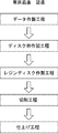
- a data production process as a data production step As shown in FIG. 3, in this embodiment, a data production process as a data production step, a disk frame production process as a modeling step, a resin disk production process as a block production step, a cutting process and a finishing process as a cutting step are performed.
- the base denture 10 By performing in order, the base denture 10 is manufactured.
- the data preparation process is also a design process.
- the CAD program 52 is activated in the main processing device 32, and the denture data as the three-dimensional data of the base denture 10 to be manufactured and the tertiary of the disk frame 60. Production (design) of the disk frame data as original data is performed.
- FIG. 5 is a perspective view illustrating an example of a display image of the display device 44.
- a denture image 10 ⁇ / b> A as a three-dimensional image of the plate denture 10 (denture base 12 and artificial tooth 14) to be manufactured and a disk as a three-dimensional image of the disk frame 60.
- the input device 42 such as a keyboard and a mouse is operated so that the frame image 60 ⁇ / b> A is displayed on the display device 44.
- CAD / CAM technology is widely used in the field of dentistry, and it is a CAD application software that allows the design of denture bases, artificial teeth, artificial tooth arrangements, and dentures with artificial teeth arranged in the denture base that are suitable for the subject.
- CAD program 52 not only the dedicated application software but also any of the provided CAD application software may be applied, and the artificial teeth 14 are arranged in the denture base 12 so as to suit the subject.
- the platen denture 10 is designed.
- an artificial tooth In the field of dentistry, various types of ready-made artificial teeth that take into consideration various physical properties such as durability, hardness, and shape as well as aesthetics are provided.
- An artificial tooth can be formed using a crown-colored resin, but it can be said that it is more efficient to use a ready-made artificial tooth with a well-established physical properties and aesthetics rather than forming an artificial tooth with a crown-colored resin. . From here, it is preferable to use the artificial tooth selected from the ready-made artificial teeth so that the color and the shape are suitable for the subject as the artificial teeth 14 for the prepared denture 10 to be manufactured.
- the three-dimensional data of the artificial tooth 14 the three-dimensional data of the selected ready-made artificial tooth is used.
- three-dimensional data in which the arrangement of the denture base 12, the artificial teeth 14, and the artificial teeth 14 is suitable for the subject can be easily obtained for the base denture 10 to be manufactured. That is, based on the three-dimensional denture base data of the denture base 12 and the three-dimensional artificial tooth data including the artificial teeth 14 arranged in the denture base 12 and the arrangement of the artificial teeth 14, the three-dimensional denture data is obtained. Produced.
- the disk frame 60 is designed according to the bedded denture 10 and the milling machine 36 used in the cutting process, and disk frame data as three-dimensional data of the disk frame 60 is produced. As shown in FIG. 5, the disk frame data is created such that the disk frame image 60 ⁇ / b> A has a ring portion 68 as a positioning portion added to the frame portion 62. The ring portion 68 is used for positioning the disk frame 60 with respect to the milling machine 36. The ring portion 68 protrudes outward from the outer peripheral surface at the axially intermediate portion of the frame portion 62 and is formed over the entire periphery of the frame portion 62.
- the position of the ring portion 68 in the axial direction of the frame portion 62 (for example, the center position in the axial direction), the width (dimension in the axial direction), and the protruding height along the radial direction of the frame portion 62 match the milling machine 36. Determined.
- the positioning portion of the disk frame 60 is formed in accordance with the milling machine 36 used in the cutting process, and is not necessarily limited to the ring portion 68.
- the disk frame data (disk frame image 60A) is configured such that the holding holes 70 are added in pairs on both sides in the diameter direction of the frame portion 62 (in this embodiment, the lip side and the throat side in the denture image 10A).
- the pair of holding holes 70 are added so as to penetrate the frame portion 62 in the axial direction.
- the pair of holding holes 70 is added so that a line connecting the axes of the pair of holding holes 70 in the plan view is a symmetric line of the resin filling portion 64.
- the holding hole 70 is also added in accordance with the milling machine 36 and is not necessarily limited to the holding hole 70.
- the occlusal surface side of the artificial tooth 14 is directed to the bottom plate 66 side of the resin filling portion 64, and the arrangement of the denture base 12 and the artificial tooth 14 is a pair of holdings.
- the plate denture image 10 ⁇ / b> A and the disk frame image 60 ⁇ / b> A are overlapped.
- the disk frame data is produced so that the plate denture image 10A (the denture base 12 and the artificial tooth 14) is accommodated in the resin filling portion 64 in the disk frame image 60A. Further, when the plate denture image 10 ⁇ / b> A is superimposed on the disk frame image 60 ⁇ / b> A, each occlusal surface side portion of the artificial tooth 14 is disposed so as to be fitted into the bottom plate 66.
- the bottom plate 66 is formed as a positioning part for positioning the artificial tooth 14 on the disk frame 60 by removing a portion overlapping each artificial tooth 14 as a concave fitting part 72.
- the bottom plate 66 in the disc frame data includes the throat side alveolar portion 16A and A recess 74 for preventing the interference is formed. That is, the resin filling unit 64 may be of a minimum size necessary for accommodating the denture image 10A, and as shown in FIG. 4, in this embodiment, the partition plate 62A, The partition part 62B and the recessed part 74 are formed.
- the relative position between the plate denture data (bed denture image 10A) and the disk frame data (disk frame image 60A) is determined, and the denture base data that becomes the three-dimensional data of the denture base 12 And denture data and disc frame data including artificial tooth data that is three-dimensional data of each artificial tooth 14 (including the arrangement).
- the modeling program 54A is activated in the main processing device 32, and the disk frame 60 is modeled by the 3D printer 34 from the three-dimensional data of the disk frame 60.
- the rapid prototype method is applied to produce the disk frame 60 as a stereoscopic image.
- Modeling methods in the rapid prototype method include binder injection method, directed energy volume method, material extraction method, material injection method, powder bed melt bonding method, sheet lamination method, liquid tank photopolymerization method, additive manufacturing method, There are an optical modeling method, a powder modeling method, a hot melt lamination method, an inkjet method, and the like. Any method may be applied in the disk frame manufacturing process.
- a three-dimensional modeling apparatus that models a three-dimensional object by a stereolithography method using a photocurable resin liquid (a photocurable resin) as a modeling material has become widespread.
- a 3D printer to which the law is applied for example, Form2: trade name manufactured by Formlabs is used.
- the cross-sectional data (slice data) obtained by dividing the disk frame data by the stacking pitch is used, and light corresponding to the cross-sectional data is irradiated to the platform (tray) in the photocurable resin liquid.
- a photocurable resin liquid is photocured to form a cured layer on the lower surface of the platform.
- the hardened layer is laminated by repeating the light irradiation according to the cross-sectional data while moving (raising) the platform on which the hardened layer is formed by the lamination pitch.
- the 3D printer 34 forms the disk frame 60 from the disk frame data.
- a ring portion 68 and a pair of holding holes 70 are formed in the frame portion 62, and the fitting portions 72 and the denture base 12 of the artificial teeth 14 are formed in the bottom plate 66 of the resin filling portion 64.
- a recess 74 corresponding to the throat side alveolar part 16A is formed.
- the frame portion 62 is formed with a partition plate 62A and a partition portion 62B.
- the artificial teeth 14 are arranged on the bottom plate 66 of the disk frame 60, and the liquid floor resin 76 forming the denture base 12 is poured into the resin filling portion 64 in which the artificial teeth 14 are arranged on the bottom plate 66 ( Resin filling step).
- the floor resin 76 poured into the resin filling portion 64 is polymerized and cured (curing process).
- FIG. 6A is a perspective view showing the disk frame 60 in a state where the artificial teeth 14 are arranged.
- 6B is a perspective view of the disk frame 60 in the middle of filling the floor resin 76
- FIG. 6C is a perspective view of the disk frame 60 filled with the floor resin 76 (corresponding to the resin disk 78 described below). It is shown in the figure.
- the artificial teeth 14 arranged in the disk frame 60 artificial teeth (off-the-shelf artificial teeth) applied (selected) in the data preparation process are used. Therefore, like the conventional full denture that does not use CAD / CAM technology, the artificial tooth 14 has a reputation for aesthetics.
- the bottom plate 66 of the disk frame 60 is formed with a recessed fitting portion 72 corresponding to each occlusal surface side portion of the artificial tooth 14.
- each of the artificial teeth 14 is arranged on the bottom plate 66 with the occlusal surface side portion inserted into the fitting portion 72.
- an adhesive is applied to the inner surface of each of the fitting portions 72 of the bottom plate 66 to bond each of the artificial teeth 14 to the bottom plate 66.
- the artificial teeth 14 are positioned on the bottom plate 66 and joined to the bottom plate 66 (disk frame 60), so that the artificial teeth 14 are arranged on the bottom plate 66 and temporarily fixed according to the artificial tooth data.
- the fitting portion 72 may not be concave as long as the artificial teeth 14 can be arranged based on the artificial tooth data.
- the artificial tooth 14 may be positioning that does not depend on the fitting portion 72, simply fitting into the fitting portion 72 without using an adhesive or the like, or temporary fixing to the fitting portion 72 with an adhesive or the like.
- a liquid floor resin 76 is poured into the resin filling portion 64 of the disk frame 60.
- various floor resins (resin materials) for forming the denture base 12 are provided.
- the floor resin 76 a resin (resin) that is cured by polymerization is used.
- the floor resin 76 has low water absorption, excellent dimensional stability, excellent impact resistance in a wide temperature range, excellent wear resistance, self-lubricating properties, excellent chemical resistance, low specific gravity, A resin having various properties as a denture base such as excellent weather resistance and biocompatibility is applied. Further, as the floor resin 76, a resin capable of obtaining a color suitable for the subject is applied.
- a room temperature polymerization resin (for example, a fit resin: trade name manufactured by Matsukaze Co., Ltd.) is used as the floor resin 76.
- the floor resin 76 is not limited to a room temperature polymerization resin, and other types of resins such as a heat polymerization resin, a pressure polymerization resin, and a photopolymerization resin can be used, and is not limited to a casting resin.
- each of the artificial teeth 14 is positioned on the bottom plate 66 and temporarily fixed. For this reason, when the liquid floor resin 76 is poured into the resin filling portion 64, the artificial teeth 14 can be prevented from being detached from the bottom plate 66, and the inclination of the artificial teeth 14 with respect to the bottom plate 66 can be suppressed. Each of the teeth 14 can be maintained positioned relative to the disk frame 60.
- the floor resin 76 poured into the resin filling part 64 is polymerized and cured.
- the disk frame 60 in which the resin filling portion 64 is filled with the liquid floor resin 76 is placed in a predetermined heating polymerization environment (for example, 0.2 MPa, 50 ° C.) for a predetermined time (for example, 30 minutes). Do it while promoting.
- the resin disk 78 shown in FIG. 6C is manufactured.
- the resin disk 78 is a so-called customized disk in which artificial teeth 14 having a shape and arrangement suitable for the subject are embedded in the floor resin 76.
- a ring portion 68 and a pair of holding holes 70 are formed in a frame portion 62 that forms an outer peripheral portion.
- FIG. 7 is a perspective view of the resin disk 78 cut in the cutting process.
- a cutting device for example, DWX52D: DWX52D: which can be simultaneously controlled and numerically controlled by the holder with respect to the cutting tool on the X axis, the Y axis, the Z axis, and five axes around these two axes. DGSSHAPA product name
- the resin disk 78 for example, the ring portion 68 is fitted into an annular (ring-shaped) holder of the milling machine 36, and a positioning pin for the milling machine 36 is inserted into each of the pair of holding holes 70. Accordingly, the resin disk 78 is positioned and held and fixed to the milling machine 36 (illustration of the mounted state is omitted).
- the cutting program 54B is started in the main processing device 32, and the denture data is read, and the main processing device 32 performs milling so as to cut the resin disk 78 based on the denture data.
- the machine 36 is controlled.
- the floor resin 76 in the resin filling portion 64 is cut in accordance with the bed denture data, and the denture base 12 is cut out from the floor resin 76.
- the artificial teeth 14 are arranged in the bottom plate 66 of the disc frame 60 and embedded in the floor resin 76.
- the resin disc 78 (the bottom plate 66 and the floor resin 76 of the disc frame 60) is cut based on the three-dimensional data of the bedded denture 10, whereby the denture base 12 is cut out and the floor covering the artificial teeth 14 is cut.
- the resin 76 is removed from the surface of the artificial tooth 14. Further, the surface of the artificial tooth 14 is also cut. Thereby, the denture base 10 in which the denture base 12 and the artificial tooth 14 are integrated is cut out from the resin disk 78.
- the denture base 10 is removed from the remaining resin disc 78, and the surface finish of the denture base 12 and each artificial tooth 14 is adjusted according to the subject. Thereby, the base denture 10 (refer FIG. 1) suitable for a test subject is obtained.
- the denture base 12 is cut out using the three-dimensional data of the base denture 10, and the floor resin 76 attached to the artificial tooth 14 is removed, and the surface of the artificial tooth 14 is polished. Cut.
- the three-dimensional data (bed denture data) of the denture 10 produced by the arrangement of the artificial teeth 14 due to a slight misalignment or the like when the artificial teeth 14 are fitted to the bottom plate 66 of the disk frame 60 are completely obtained. Even if they do not match, the plate denture 10 can be finished according to the three-dimensional data, and the return accuracy of the artificial tooth 14 can be improved.
- the artificial teeth 14 arranged according to the three-dimensional data of the plate denture 10 need not be cut.
- the denture base data of the denture base 12 and the artificial tooth data of the artificial tooth 14 arranged in the denture base 12 are manufactured.
- the base denture data of the base denture 10 including is produced.
- a liquid floor resin 76 is poured into the resin filling portion 64 of the disk frame 60 in which the occlusal surface side of the artificial tooth 14 is the bottom plate 66 side and the artificial tooth 14 is arranged on the bottom plate 66 based on the artificial tooth data.
- a resin disc 78 in which the artificial tooth 14 is embedded in the floor resin 76 is produced.
- the prepared resin disc 78 is obtained by cutting the denture base 12 by cutting the base resin 76 based on the denture data, and the base side of the artificial tooth 14 embedded in the denture base 12. 10 is manufactured.
- the artificial tooth 14 is bonded to the bottom plate 66 of the disk frame 60, and the base side of the artificial tooth 14 is superposed on the floor resin 76, so that the artificial tooth 14 is firmly attached to the floor resin 76.
- the artificial tooth 14 is firmly joined to the denture base 12. For this reason, in the denture base 10, it is suppressed that the artificial tooth 14 remove
- the denture base 12 since the denture base 12 is cut out from the floor resin 76 in the state in which the artificial tooth 14 is embedded, the return accuracy of the artificial tooth 14 can be improved.
- the artificial tooth 14 and the denture base 12 may be joined not only by chemical joining but also by physical joining such as fitting the base side of the artificial tooth 14 and the floor resin 76.
- the artificial tooth and the denture base are manufactured separately and the artificial tooth is fitted into the denture base, if there is an undercut on the base side of the artificial tooth, it is difficult to fit the artificial tooth into the denture base. Become.
- the liquid floor resin 76 is poured into the resin filling portion 64 in which the artificial teeth 14 are arranged, the undercut portion of the artificial teeth 14 can be appropriately embedded in the floor resin 76, and the artificial teeth 14 are dentured. It can be firmly joined to the floor 12 (without a gap).
- the artificial tooth 14 is positioned with respect to the disk frame 60 and arranged based on the artificial tooth data. For this reason, it can suppress that the position of the artificial tooth 14 with respect to the denture base 12 can be suppressed, and the base denture 10 can be manufactured with high precision.
- a fitting portion 72 is formed on the bottom plate 66 of the disk frame 60, and the portion on the occlusal surface side of the artificial tooth 14 is fitted to the fitting portion 72.
- the artificial tooth 14 can be easily and accurately positioned with respect to the disk frame 60, and the positional deviation of the artificial tooth 14 can be suppressed, and the return accuracy of the artificial tooth 14 can be improved.
- the bottom plate 66 of the disk frame 60 is formed with a recess 74 corresponding to the throat side alveolar portion 16A of the denture base 12.
- the occlusal surface side of the artificial tooth 14 is fitted into the fitting part 72, the floor resin 76 of the throat side alveolar part 16A is insufficient, and the throat side alveolar part 16A can be cut into an appropriate shape. It can prevent becoming impossible, and can manufacture the denture 10 of the appropriate shape without a chip
- the resin disc 78 manufactured using the disc frame 60 can be accurately positioned on the milling machine 36. For this reason, the artificial tooth 14 can be accurately positioned with respect to the milling machine 36, and it is possible to effectively suppress the displacement of the artificial tooth 14 with respect to the denture base 12.
- the bed denture 10 is overlapped on the disk frame 60 to prepare the bed denture data and the disk frame data, and the disk frame 60 is formed using the produced disk frame data. Thereby, the disk frame 60 adapted to the size of the denture 10 can be manufactured.
- the disk frame 60 is provided with a partition plate 62A and a partition portion 62B, and a recess 74 is formed in the bottom plate 66, so that the minimum volume necessary for filling the resin capable of scraping the denture base 12 is provided.
- a resin filling portion 64 is formed. For this reason, the capacity
- the occlusal surface side portion of the artificial tooth 14 of the denture image 10A is superimposed on the bottom plate 66 of the disc frame image 60A.
- the artificial teeth 14 can be properly positioned and arranged on the bottom plate 66 of the disk frame 60.
- the artificial teeth 14 can be easily positioned with respect to the disk frame 60.
- the substantially cylindrical disk frame 60 is used.
- the frame is not limited to a bottomed cylindrical shape, and the artificial teeth 14 can be arranged inside and the floor resin 76 can be filled. Good.
- the height of the frame body only needs to be a height at which the denture base 12 can be formed by the filled floor resin 76.
- the outer shape of the frame is not limited to a circular shape in plan view, and may be a polygon such as a triangle or a quadrangle, or a semicircle. Since the outer shape in plan view of the frame is a polygonal shape or a semicircular shape, the corners can be used for positioning with respect to the cutting device, and therefore the positioning holes such as the holding holes 70 can be omitted.
- the floor resin 76 is filled up to the upper end of the disk frame 60, but the floor is formed to such an extent that the denture base 12 can be formed (for example, slightly more than FIG. 6B). Cutting may be performed with the resin 76 filled.
- the fitting portion 72 in which the occlusal surface side portion of the artificial tooth 14 is inserted into the bottom plate 66 of the disk frame 60 is formed.
- the frame may be formed with a fitting portion into which the base side opposite to the occlusal surface of the artificial tooth is inserted.
- the resin used for producing the frame is not limited, but it is preferable to use the same resin as the floor resin for the frame.
- sequence of the artificial tooth may be formed in a frame, and a fitting part may be formed in this raised part. Thereby, a frame can be used as a part of denture base.
- the base side of the artificial teeth is firmly fixed to the frame body by using a fixing means such as an adhesive.
- a fixing means such as an adhesive.
- the floor resin is placed so that the base side of the artificial tooth is embedded in the denture base in the denture. What is necessary is just to fill, and this can suppress the quantity of the floor resin with which a frame is filled.
- the base side of the artificial tooth is positioned on the frame, it is possible to produce a resin block that is a so-called customized disk in which artificial teeth 14 having a shape and arrangement suitable for the subject are embedded in the floor resin 76. become.
- the resin block produced in this way is cut based on the bed denture data using a cutting device such as a milling machine 36, whereby a bed denture based on the bed denture data is manufactured.
- the plate denture is cut out with respect to the frame body in a direction different from that in FIG. 7 (upside down direction).
- the dentures manufactured in this way a part of the frame is used as a denture base, and the base side of the artificial tooth is embedded in the floor resin, so that the artificial tooth and the denture base can be made stronger. Can be joined. An artificial tooth excellent in aesthetics can be used for the denture. Furthermore, since the resin block is cut based on the denture data and the denture is cut out, a denture with good return accuracy of the artificial tooth can be manufactured.
- the main processing device 32 of the manufacturing system 30 three-dimensional denture data for the denture 10 including the denture base data and artificial tooth data was created.
- the plate denture data may be created by another CAD device different from the main processing device 32.
- the manufacturing system 30 may function so as to include the data acquisition step in the data preparation step.
- the denture denture data produced by the main processing device 32 using another CAD device is obtained via a network line or a portable (or portable) storage medium (such as a USB memory). What is necessary is just to manufacture the plate denture 10 using the prepared plate denture data.
- the denture and the denture 10 as a full denture have been described as examples.
- the denture is not limited to this, and the denture may be a partial denture. Good.
- the denture is not limited to the lower denture and may be an upper denture.
Abstract
In the present invention, disk frame data for a disk frame for accommodating a plate denture is generated while generating plate denture data for the plate denture, and the disk frame is formed on the basis of the disk frame data. Next, synthetic teeth are arranged within the disk frame and a plate resin is cured to provide a resin disk in which the synthetic teeth are implanted. The resin disk is cut on the basis of the plate denture data to cut out a denture plate, thereby producing a plate denture in which the root parts of the synthetic teeth are implanted in the denture plate. Accordingly, it is possible to produce a plate denture using synthetic teeth that are aesthetically appealing, the plate denture allowing for secure bonding between the synthetic teeth and the denture plate and accurate positioning of the synthetic teeth.
Description
本発明は、義歯床に人工歯が排列された有床義歯の製造方法、有床義歯及び有床義歯の製造装置に関する。
The present invention relates to a method for manufacturing a plate denture in which artificial teeth are arranged on a denture base, a plate denture, and a device for manufacturing a plate denture.
口腔内における歯科補綴物には、部分床義歯や全部床義歯などの有床義歯がある。有床義歯は、義歯床を土台として義歯床上に一つ又は複数の人工歯が排列された義歯であり、有床義歯は、義歯床の粘膜対向面が口腔内において歯肉粘膜面に密着されて装着される。
歯 科 Dental prostheses in the oral cavity include base dentures such as partial dentures and complete dentures. A denture is a denture in which one or more artificial teeth are arranged on the denture base on the basis of the denture base, and the mucosal facing surface of the denture base is in close contact with the gingival mucosa surface in the oral cavity. Installed.
近年、切削技術及び造形技術の向上に伴い、高精度な切削加工や造形が可能となっている。ここから、CAD/CAM技術を利用して人工歯や義歯床を製造して、有床義歯を製造する各種の方法が提案されている。
In recent years, with the improvement of cutting technology and modeling technology, highly accurate cutting and modeling are possible. From here, various methods of manufacturing artificial dentures and denture bases using CAD / CAM technology and manufacturing base dentures have been proposed.
例えば、特表2013-512695号公報では、義歯のデジタルデータを取得し、取得したデジタルデータから有床義歯を製造する方法が提案されている。特表2013-512695号公報の技術では、デジタルデータを歯列弓のモデルデータと義歯床のモデルデータとに分離し、切削技術又は造形技術を用いて、歯列弓のモデルデータから複数の人工歯を一体化した歯列弓を製造すると共に、義歯床のモデルデータから義歯床を製造する。この後、製造した歯列弓と義歯床とを接着あるいは接合することで、有床義歯を得るように提案している。
For example, Japanese Patent Publication No. 2013-512695 proposes a method of acquiring denture digital data and manufacturing a bed denture from the acquired digital data. In the technique of Japanese translations of PCT publication No. 2013-512695, digital data is separated into dental arch model data and denture base model data, and a plurality of artificial artificial arch model data is obtained from the dental arch model data using cutting or modeling techniques. A dental arch with integrated teeth is manufactured, and a denture base is manufactured from denture base model data. Thereafter, it is proposed to obtain a denture by bonding or joining the manufactured dental arch and a denture base.
ところで、口腔内に装着される有床義歯には、粘膜面との適合精度及び咬合関係の再現性が要求される。特に咬合関係の再現性が低下することで、口腔内において有床義歯が有効に機能しなくなる。これまでのCAD/CAM技術を応用した有床義歯の製造方法は、粘膜面との良好な適合は得ることができるが、特許文献1の技術のように人工歯と義歯床とを製造して、製造した人工歯を義歯床に接合した場合、義歯のデジタルデータ通りに人工歯を正しく所定の位置に接合させる精度(人工歯の戻り精度)を得ることができず、咬合関係の再現性が得られないという問題がある。また、特許文献1の技術のような歯列弓では、個々の人工歯の審美性が悪くなる(審美性が得られなくなる)という問題がある。さらに、個別に製造された人工歯と義歯床とは、強固な接合が難しいという問題もある。
By the way, the dentures installed in the oral cavity are required to be compatible with the mucosal surface and have reproducibility of the occlusal relationship. In particular, the reproducibility of the occlusal relationship is reduced, so that the denture does not function effectively in the oral cavity. Conventional methods for manufacturing dentures using CAD / CAM technology can obtain a good fit with the mucosal surface, but as in the technique of Patent Document 1, artificial teeth and denture bases are manufactured. When the manufactured artificial tooth is joined to the denture base, the accuracy of joining the artificial tooth correctly to the predetermined position (the return accuracy of the artificial tooth) according to the digital data of the denture cannot be obtained, and the reproducibility of the occlusal relationship is There is a problem that it cannot be obtained. Moreover, in the dental arch like the technique of patent document 1, there exists a problem that the aesthetics of each artificial tooth will worsen (the aesthetics will no longer be obtained). Furthermore, there is a problem in that it is difficult to bond the artificial tooth and the denture base manufactured separately.
本発明は上記事実に鑑みてなされたものであり、人工歯と義歯床とを強固に接合可能な有床義歯の製造方法、有床義歯及び有床義歯の製造装置の提供を目的とする。
The present invention has been made in view of the above-mentioned facts, and an object thereof is to provide a method for producing a denture capable of firmly joining an artificial tooth and a denture base, a bed denture, and a device for producing a bed denture.
本発明の態様に係る有床義歯の製造方法は、製造する有床義歯について、義歯床の三次元の義歯床データ、及び前記義歯床に排列する人工歯と該人工歯の排列とを含む三次元の人工歯データを作製して、三次元の有床義歯データを作製するデータ作製ステップと、枠体内に前記人工歯データに基づいて前記人工歯を排列し、前記人工歯を排列した前記枠体内に前記義歯床を形成する床レジンを充填することでレジンブロックを作製するブロック作製ステップと、切削装置を用いて前記レジンブロックを前記有床義歯データに基づいて切削することで、前記義歯床に前記人工歯が排列された有床義歯を削り出す切削ステップと、を含む。
A method for producing a denture according to an aspect of the present invention includes a three-dimensional denture base data of a denture base, an artificial tooth arranged in the denture base, and an arrangement of the artificial tooth for the denture to be produced. A data creation step for creating original artificial tooth data and creating three-dimensional denture data, and arranging the artificial tooth in the frame based on the artificial tooth data, and arranging the artificial tooth in the frame A step of preparing a resin block by filling a base resin forming the denture base in the body, and cutting the resin block on the basis of the denture data using the cutting device using a cutting device; Cutting a plate-like denture in which the artificial teeth are arranged.
本発明の態様に係る有床義歯は、義歯床の三次元の義歯床データ、及び前記義歯床に排列する人工歯と該人工歯の排列とを含む三次元の人工歯データを作製して、三次元の有床義歯データを作製するデータ作製ステップと、枠体内に前記人工歯データに基づいて前記人工歯を排列し、前記人工歯を排列した前記枠体内に前記義歯床を形成する床レジンを充填することでレジンブロックを作製するブロック作製ステップと、切削装置を用いて前記レジンブロックを前記有床義歯データに基づいて切削することで、前記義歯床に前記人工歯が排列された有床義歯を削り出す切削ステップと、を含む有床義歯の製造方法により製造されている。
The denture according to the aspect of the present invention, the three-dimensional artificial tooth data including the three-dimensional denture base data of the denture base, and the artificial teeth arranged in the denture base and the arrangement of the artificial teeth, A data preparation step for generating three-dimensional denture data, and a floor resin that arranges the artificial teeth in the frame based on the artificial tooth data and forms the denture base in the frame in which the artificial teeth are arranged A block production step of producing a resin block by filling the base plate, and a bed with the artificial teeth arranged in the denture base by cutting the resin block based on the base denture data using a cutting device And a cutting step for cutting the denture.
本発明の態様に係る有床義歯の製造装置は、製造する有床義歯について、義歯床の三次元の義歯床データ、及び前記義歯床に排列する人工歯と該人工歯の排列とを含む三次元の人工歯データを作製して、三次元の有床義歯データを作製する設計部と、枠体内に前記人工歯データに基づいて前記人工歯が排列され、前記人工歯を排列した前記枠体内に前記義歯床を形成する床レジンが充填されたレジンブロックに対し、切削加工を行う切削装置と、前記有床義歯データに基づいて前記レジンブロックが切削されるように前記切削装置を制御して、前記義歯床に前記人工歯が排列された有床義歯を削り出す制御部と、を含む。
An apparatus for producing a denture according to an aspect of the present invention includes a three-dimensional denture base data of a denture base, an artificial tooth arranged in the denture base, and an arrangement of the artificial tooth for the denture to be produced. A design unit that creates original artificial tooth data and creates three-dimensional denture data, and the artificial tooth is arranged based on the artificial tooth data in the frame, and the artificial tooth is arranged in the frame A cutting device for cutting the resin block filled with the floor resin forming the denture base, and controlling the cutting device so that the resin block is cut based on the denture data And a control unit that cuts out the denture with the artificial teeth arranged in the denture base.
以上説明したように本発明の態様によれば、人工歯と義歯床とを強固に接合した有床義歯を製造できる、という効果を有する。しかも、本発明の態様によれば、人工歯の戻り精度が良好で、審美性に優れた人工歯を使用することができて、高品質の有床義歯を製造できる。
As described above, according to the aspect of the present invention, there is an effect that it is possible to manufacture a denture with a strong joint between an artificial tooth and a denture base. Moreover, according to the aspect of the present invention, it is possible to use an artificial tooth with good return accuracy of the artificial tooth and excellent aesthetics, and it is possible to manufacture a high-quality denture.
本実施形態では、以下の態様を含む。
<1> 製造する有床義歯について、義歯床の三次元の義歯床データ、及び前記義歯床に排列する人工歯と該人工歯の排列とを含む三次元の人工歯データを作製して、三次元の有床義歯データを作製するデータ作製ステップと、枠体内に前記人工歯データに基づいて前記人工歯を排列し、前記人工歯を排列した前記枠体内に前記義歯床を形成する床レジンを充填することでレジンブロックを作製するブロック作製ステップと、切削装置を用いて前記レジンブロックを前記有床義歯データに基づいて切削することで、前記義歯床に前記人工歯が排列された有床義歯を削り出す切削ステップと、を含む有床義歯の製造方法。 The present embodiment includes the following aspects.
<1> A three-dimensional artificial tooth data including a three-dimensional denture base data of the denture base and an artificial tooth arranged on the denture base and an arrangement of the artificial tooth is prepared for the denture to be manufactured, A data production step for creating original denture data, and a floor resin for arranging the artificial tooth in the frame based on the artificial tooth data and forming the denture base in the frame in which the artificial tooth is arranged Block production step for producing a resin block by filling, and a denture with the artificial teeth arranged in the denture base by cutting the resin block based on the denture data using a cutting device A method of manufacturing a denture having a cutting step.
<2> 前記切削ステップは、前記人工歯を前記人工歯データに基づいて切削することを含む<1>の有床義歯の製造方法。
<2> The method for manufacturing a denture according to <1>, wherein the cutting step includes cutting the artificial tooth based on the artificial tooth data.
<3> 前記人工歯は、前記人工歯データに基づいて前記枠体に対して位置決めされて前記枠体内の底板に排列される<1>又は<2>の有床義歯の製造方法。
<3> The method for manufacturing a denture according to <1> or <2>, wherein the artificial tooth is positioned with respect to the frame body based on the artificial tooth data and arranged in a bottom plate in the frame body.
<4> 前記人工歯が前記人工歯データに基づいて排列された際に、前記人工歯の咬合面側部分又は咬合面とは反対側の基部側部分が嵌入される嵌合部が前記枠体内の底板に設けられる<1>から<3>の何れか1の有床義歯の製造方法。
<4> When the artificial tooth is arranged based on the artificial tooth data, a fitting portion into which the occlusal surface side portion of the artificial tooth or the base side portion opposite to the occlusal surface is inserted is the frame body. <1> to <3> provided in the baseplate of any one of <1>.
<5> 前記枠体内に排列される前記人工歯が、前記切削装置に対して位置決めされる位置決め部が前記枠体に設けられた<1>から<4>の何れか1の有床義歯の製造方法。
<5> The artificial tooth arranged in the frame body is provided with a positioning portion for positioning the artificial tooth with respect to the cutting device. Production method.
<6> 造形装置を用い、前記枠体を該枠体の三次元の枠体データに基づいて造形する造形ステップを含み、前記有床義歯データに合せて前記枠体データが作製される<1>から<5>の何れか1の有床義歯の製造方法。
<6> Using a modeling apparatus, including a modeling step of modeling the frame based on the three-dimensional frame data of the frame, the frame data is produced in accordance with the denture data <1 > To <5>.
<7> 前記枠体データは、前記有床義歯データで表される有床義歯画像が前記枠体データで表される枠体画像内に収容されるように相対位置が定められて作製される<6>の有床義歯の製造方法。
<8> 前記枠体データは、前記枠体画像の底板に前記有床義歯画像の人工歯の咬合面側部分又は咬合面とは反対側の基部側部分が重ねられることで、該重なり部分が前記枠体画像の底板から除かれて作製される、ことを含む<7>の有床義歯の製造方法。 <7> The frame body data is created with a relative position determined such that a floor denture image represented by the floor denture data is accommodated in a frame body image represented by the frame body data. <6> The manufacturing method of the denture of dentures.
<8> The frame data is obtained by overlapping the occlusal surface side portion of the artificial tooth or the base side portion opposite to the occlusal surface of the artificial denture image on the bottom plate of the frame image. <7> The method for manufacturing a denture according to <7>, comprising removing the bottom image from the bottom plate of the frame image.
<9> <1>から<8>の何れか1の有床義歯の製造方法により製造された有床義歯。
<10> 製造する有床義歯について、義歯床の三次元の義歯床データ、及び前記義歯床に排列する人工歯と該人工歯の排列とを含む三次元の人工歯データを作製して、三次元の有床義歯データを作製するデータ設計部と、枠体内に前記人工歯データに基づいて前記人工歯が排列され、前記人工歯を排列した前記枠体内に前記義歯床を形成する床レジンが充填されたレジンブロックに対し、切削加工を行う切削装置と、前記有床義歯データに基づいて前記レジンブロックが切削されるように前記切削装置を制御して、前記義歯床に前記人工歯が排列された有床義歯を削り出す制御部と、を含む有床義歯の製造装置。 <9> A plate denture manufactured by the method for manufacturing a plate denture according to any one of <1> to <8>.
<10> A three-dimensional artificial tooth data including a three-dimensional denture base data of a denture base and an artificial tooth arranged on the denture base and an arrangement of the artificial tooth for the denture to be manufactured, A data design unit for producing original denture data, and a floor resin in which the artificial teeth are arranged based on the artificial tooth data in the frame, and the denture base is formed in the frame in which the artificial teeth are arranged. A cutting device that performs cutting on the filled resin block, and the cutting device is controlled so that the resin block is cut based on the denture data, and the artificial teeth are arranged in the denture base. And a control unit that scrapes the dentured denture.
以下、図面を参照して本態様の実施形態を詳細に説明する。
本実施形態では、有床義歯の製造を説明する。本実施形態では、CAD(Computer Aided Design、コンピュータ支援による設計)技術及びCAM(Computer Aided Manufacturing、コンピュータ支援による製造)技術(CAD/CAM技術)を用いて被験者(患者)に適合した有床義歯を製造する。 Hereinafter, embodiments of the present aspect will be described in detail with reference to the drawings.
In the present embodiment, the manufacture of a plate denture will be described. In this embodiment, a denture suitable for a subject (patient) using CAD (Computer Aided Design) technology and CAM (Computer Aided Manufacturing) technology (CAD / CAM technology) is used. To manufacture.
本実施形態に係る有床義歯は、上顎義歯であってもよく、下顎義歯であってもよい。また、本実施形態に係る有床義歯は、部分床義歯(一部義歯)であってもよく、全部床義歯(総義歯)であってもよい。
The bed denture according to this embodiment may be an upper denture or a lower denture. Moreover, the partial denture which concerns on this embodiment may be a partial denture (partial denture), and may be a complete denture (complete denture).
図1には、本実施形態に係る下顎義歯及び全部床義歯としての有床義歯10の外観が斜視図にて示されている。なお、図面では、Z軸方向が上側とされ、X軸方向が口腔内における咽喉側に対応され、Y軸方向が口腔内における左頬側に対応されている。
FIG. 1 is a perspective view showing the external appearance of a lower denture and a full denture 10 as a complete denture according to this embodiment. In the drawing, the Z-axis direction is the upper side, the X-axis direction corresponds to the throat side in the oral cavity, and the Y-axis direction corresponds to the left cheek side in the oral cavity.
図1に示すように、有床義歯10は、歯肉側の義歯床12及び義歯床12上に排列された複数の人工歯14を備えている。義歯床12は、平面視において略山形状(略弓状)とされており、頂部が口腔内の唇側とされる。また、義歯床12は、上下方向い沿う断面(断面の図示は省略)が略山形状とされており、略山形状断面における頂部が歯槽部16とされている。口腔内において下顎側の歯肉は、咽喉側部分が上顎側(上側)に向けて湾曲しており、義歯床12の歯槽部16には、歯肉の咽喉側湾曲部分を覆う咽喉側歯槽部16Aが形成されている。
As shown in FIG. 1, the denture 10 includes a denture base 12 on the gingival side and a plurality of artificial teeth 14 arranged on the denture base 12. The denture base 12 is substantially mountain-shaped (substantially arcuate) in plan view, and the top is the lip side in the oral cavity. Further, the denture base 12 has a substantially mountain-shaped cross section along the vertical direction (the cross section is not shown), and the top of the substantially mountain-shaped cross section is the alveolar portion 16. In the oral cavity, the gingiva on the lower jaw side is curved toward the upper jaw side (upper side), and the alveolar portion 16A covering the throat side curved portion of the gingiva is provided in the alveolar portion 16 of the denture base 12. Is formed.
義歯床12は、口腔内において咽喉側部分が舌側床翼部18とされ、口腔内において唇側部分が唇側床翼部20とされていると共に、唇側床翼部20の両頬側(左右方向両側)が頬側床翼部22とされている。義歯床12では、唇側床翼部20及び頬側床翼部22の各々と舌側床翼部18とが歯槽部16において一体にされている。
The denture base 12 has a throat side portion as a lingual floor wing portion 18 in the oral cavity, a lip side portion as a lip side floor wing portion 20 in the oral cavity, and both cheek sides of the lip side floor wing portion 20. (Both sides in the left-right direction) are the cheek floor wings 22. In the denture base 12, each of the labial floor wing part 20 and the buccal floor wing part 22 and the lingual floor wing part 18 are integrated in the alveolar part 16.
義歯床12では、唇側床翼部20及び頬側床翼部22と舌側床翼部18との間の内面が装着面24とされている。義歯床12(有床義歯10)は、口腔内に装着される際、装着面24が下顎の歯肉(歯茎)粘膜に密着される。
In the denture base 12, the inner surface between the lip side floor wing part 20 and the buccal side floor wing part 22 and the lingual side floor wing part 18 serves as a mounting surface 24. When the denture base 12 (bed denture 10) is mounted in the oral cavity, the mounting surface 24 is in close contact with the gingival (gingival) mucosa of the lower jaw.
複数の人工歯14は、義歯床12の歯槽部16において、歯槽部16の唇側から咽喉側(咽喉側歯槽部16A側)の各々に向かって略左右対称(平面視において略左右対称)に排列されている。また、人工歯14の各々は、咬合面とは反対側の基部側の少なくとも一部が歯槽部16に埋入されて植立状態にされている。
In the alveolar part 16 of the denture base 12, the plurality of artificial teeth 14 are substantially bilaterally symmetric (substantially bilaterally symmetrical in plan view) from the lip side of the alveolar part 16 toward the throat side (the throat side alveolar part 16A side). It is arranged. In addition, each of the artificial teeth 14 is in a planted state in which at least a part of the base side opposite to the occlusal surface is embedded in the alveolar portion 16.
図2には、本実施形態に係る製造装置としてのCAD/CAM技術を利用した製造システム30の概略構成が示されており、製造システム30は、有床義歯10の製造に用いられる。
FIG. 2 shows a schematic configuration of a manufacturing system 30 using CAD / CAM technology as a manufacturing apparatus according to the present embodiment, and the manufacturing system 30 is used for manufacturing the bedded denture 10.
図2に示すように、製造システム30には、制御部及び設計部が構成される主処理装置32が設けられており、主処理装置32には、例えば、パーソナルコンピュータが用いられる。また、製造システム30には、造形装置(三次元造形装置)としての3Dプリンタ34、及び切削装置としてのミリングマシン36が設けられている。
As shown in FIG. 2, the manufacturing system 30 is provided with a main processing device 32 including a control unit and a design unit. For the main processing device 32, for example, a personal computer is used. The manufacturing system 30 is provided with a 3D printer 34 as a modeling apparatus (three-dimensional modeling apparatus) and a milling machine 36 as a cutting apparatus.
主処理装置32は、CPU、ROM、RAM等がバス(何れも図示省略)によって接続された主処理部38を備えている。また、主処理装置32は、不揮発性記憶媒体としてのHDD40、キーボードやマウス等の入力デバイス42、液晶モニタ(LCD)等の表示デバイス44、通信インターフェース46、及び入出力インターフェース48等を備えている。主処理装置32では、主処理部38、HDD40、入力デバイス42、表示デバイス44、通信インターフェース46、及び入出力インターフェース48が相互にデータ交換可能に接続されている。
The main processing device 32 includes a main processing unit 38 to which a CPU, a ROM, a RAM, and the like are connected by a bus (all not shown). The main processing device 32 includes an HDD 40 as a nonvolatile storage medium, an input device 42 such as a keyboard and a mouse, a display device 44 such as a liquid crystal monitor (LCD), a communication interface 46, an input / output interface 48, and the like. . In the main processing device 32, the main processing unit 38, the HDD 40, the input device 42, the display device 44, the communication interface 46, and the input / output interface 48 are connected so as to exchange data with each other.
主処理装置32は、主処理部38においてROMに記憶されたOS(オペレーティングシステム)をCPUが読み出してRAMに展開しながら実行することで動作する。また、HDD40には、各種のデータが記憶される記憶領域50が設けられていると共に、アプリケーションプログラムが記憶されている。主処理部38では、CPUがアプリケーションプログラムを読み出してRAMに展開しながら実行することで、アプリケーションプログラムが機能する。なお、主処理装置32は、通信インターフェース46を介して、LANや公衆通信回線網(インターネット)に接続されることで、LANや公衆通信回線網を介したデータやプログラム等の送受信が可能となっている。主処理部38は、通信インターフェース46を介して取得されるプログラムを実行してもよい。
The main processing device 32 operates when the CPU reads out an OS (operating system) stored in the ROM in the main processing unit 38 and executes it while expanding it in the RAM. In addition, the HDD 40 is provided with a storage area 50 for storing various data and an application program. In the main processing unit 38, the application program functions when the CPU reads the application program and executes it while expanding it in the RAM. The main processing device 32 is connected to a LAN or a public communication line network (Internet) via the communication interface 46, so that data and programs can be transmitted and received via the LAN or the public communication line network. ing. The main processing unit 38 may execute a program acquired via the communication interface 46.
HDD40に記憶されるアプリケーションプログラムには、CADプログラム(三次元CADソフトウェア)52及びCAMプログラム54が含まれており、CAMプログラム54には、造形プログラム54A及び切削プログラム54Bが含まれている。また、主処理装置32の入出力インターフェース48には、3Dプリンタ34及びミリングマシン36が接続されており、3Dプリンタ34及びミリングマシン36は、主処理部38によって制御される。
The application programs stored in the HDD 40 include a CAD program (three-dimensional CAD software) 52 and a CAM program 54, and the CAM program 54 includes a modeling program 54A and a cutting program 54B. The 3D printer 34 and the milling machine 36 are connected to the input / output interface 48 of the main processing device 32, and the 3D printer 34 and the milling machine 36 are controlled by the main processing unit 38.
主処理装置32は、主処理部38においてCADプログラム52が読み出されて実行されることで、三次元データを作製する設計部として機能する。また、主処理装置32は、主処理部38において造形プログラム54A及び切削プログラム54Bが読み出されて実行されることで、3Dプリンタ34を用いた造形工程としての造形部、及びミリングマシン36を用いた切削工程としての切削部として機能する。また、主処理部38は、造形工程及び切削工程における制御部として機能する。
The main processing device 32 functions as a design unit that creates three-dimensional data by reading and executing the CAD program 52 in the main processing unit 38. The main processing device 32 uses the modeling unit and the milling machine 36 as a modeling process using the 3D printer 34 by reading and executing the modeling program 54A and the cutting program 54B in the main processing unit 38. It functions as a cutting part as a cutting process. The main processing unit 38 functions as a control unit in the modeling process and the cutting process.
以下に、製造システム30における有床義歯10の製造を説明する。
製造システム30では、有床義歯10の製造に、枠体としてのディスク枠60を用いている。図3には、製造システム30を用いた有床義歯10の製造工程が流れ図にて示され、図4には、ディスク枠60の外観が斜視図にて示されている。 Below, manufacture of thebase denture 10 in the manufacturing system 30 is demonstrated.
In themanufacturing system 30, the disk frame 60 as a frame is used for manufacturing the bedded denture 10. FIG. 3 is a flowchart showing the manufacturing process of the plate denture 10 using the manufacturing system 30, and FIG. 4 is a perspective view showing the outer appearance of the disk frame 60.
製造システム30では、有床義歯10の製造に、枠体としてのディスク枠60を用いている。図3には、製造システム30を用いた有床義歯10の製造工程が流れ図にて示され、図4には、ディスク枠60の外観が斜視図にて示されている。 Below, manufacture of the
In the
図4に示すように、ディスク枠60は、有底筒状とされており、ディスク枠60は、円筒状の枠部62を備えている。枠部62には、義歯床12を形成するための床レジン76が充填されるレジン充填部64が形成されている。枠部62内には、仕切り板62A及び略山形状(略五角形状)の仕切り部62Bが設けられており、枠部62、仕切り板62A及び仕切り部62Bに囲われた空間がレジン充填部64とされている。ディスク枠60のレジン充填部64には、底板66が形成されており、レジン充填部64は、底板66によりディスク枠60の軸方向の一側が閉塞されている。
As shown in FIG. 4, the disk frame 60 has a bottomed cylindrical shape, and the disk frame 60 includes a cylindrical frame portion 62. The frame portion 62 is formed with a resin filling portion 64 that is filled with a floor resin 76 for forming the denture base 12. A partition plate 62A and a substantially mountain-shaped (substantially pentagonal) partition portion 62B are provided in the frame portion 62, and a space surrounded by the frame portion 62, the partition plate 62A, and the partition portion 62B is a resin filling portion 64. It is said that. A bottom plate 66 is formed in the resin filling portion 64 of the disk frame 60, and the resin filling portion 64 is closed on one side in the axial direction of the disk frame 60 by the bottom plate 66.
図3に示すように、本実施形態では、データ作製ステップとしてのデータ作製工程、造形ステップとしてのディスク枠作製工程、ブロック作製ステップとしてのレジンディスク作製工程、切削ステップとしての切削工程及び仕上げ工程が順に実行されることで、有床義歯10が製造される。
As shown in FIG. 3, in this embodiment, a data production process as a data production step, a disk frame production process as a modeling step, a resin disk production process as a block production step, a cutting process and a finishing process as a cutting step are performed. By performing in order, the base denture 10 is manufactured.
〔データ作製工程〕
データ作製工程は、設計工程でもあり、データ作製工程では、主処理装置32においてCADプログラム52が起動されて、製造する有床義歯10の三次元データとしての有床義歯データ及びディスク枠60の三次元データとしてのディスク枠データの作製(設計)が行われる。図5には、表示デバイス44の表示画像の一例が斜視図にて示されている。 [Data production process]
The data preparation process is also a design process. In the data preparation process, theCAD program 52 is activated in the main processing device 32, and the denture data as the three-dimensional data of the base denture 10 to be manufactured and the tertiary of the disk frame 60. Production (design) of the disk frame data as original data is performed. FIG. 5 is a perspective view illustrating an example of a display image of the display device 44.
データ作製工程は、設計工程でもあり、データ作製工程では、主処理装置32においてCADプログラム52が起動されて、製造する有床義歯10の三次元データとしての有床義歯データ及びディスク枠60の三次元データとしてのディスク枠データの作製(設計)が行われる。図5には、表示デバイス44の表示画像の一例が斜視図にて示されている。 [Data production process]
The data preparation process is also a design process. In the data preparation process, the
図5に示すように、データ作製工程では、製造する有床義歯10(義歯床12及び人工歯14)の三次元画像としての有床義歯画像10A、及びディスク枠60の三次元画像としてのディスク枠画像60Aが表示デバイス44に表示されるように、キーボード及びマウス等の入力デバイス42が操作される。
As shown in FIG. 5, in the data preparation process, a denture image 10 </ b> A as a three-dimensional image of the plate denture 10 (denture base 12 and artificial tooth 14) to be manufactured and a disk as a three-dimensional image of the disk frame 60. The input device 42 such as a keyboard and a mouse is operated so that the frame image 60 </ b> A is displayed on the display device 44.
歯科医療の分野では、CAD/CAM技術が普及しており、被験者に適合した義歯床、人工歯、人工歯排列及び人工歯を義歯床に排列した有床義歯の設計が可能なCAD用アプリケーションソフトが各種提供されている。CADプログラム52には、専用のアプリケーションソフトを用いるだけでなく、提供されるCAD用アプリケーションソフトの何れかを適用してもよく、被験者に適合するように、義歯床12に人工歯14が排列された有床義歯10の設計が行われる。
CAD / CAM technology is widely used in the field of dentistry, and it is a CAD application software that allows the design of denture bases, artificial teeth, artificial tooth arrangements, and dentures with artificial teeth arranged in the denture base that are suitable for the subject. There are various types. As the CAD program 52, not only the dedicated application software but also any of the provided CAD application software may be applied, and the artificial teeth 14 are arranged in the denture base 12 so as to suit the subject. The platen denture 10 is designed.
また、歯科医療の分野では、審美性はいうまでもなく、耐久性、硬さ、形状などの各種の物性が考慮された既製の人工歯が各種提供されている。人工歯は、歯冠色レジンを用いて形成することができるが、歯冠色レジンで人工歯を形成するよりも、物性や審美性に定評のある既製の人工歯を用いるほうが効率的といえる。ここから、製造する有床義歯10には、既製の人工歯から色や形状が被験者に適合するように選択した人工歯を人工歯14として用いることが好ましい。人工歯14の三次元データには、選択した既製の人工歯の三次元データが用いられる。
In the field of dentistry, various types of ready-made artificial teeth that take into consideration various physical properties such as durability, hardness, and shape as well as aesthetics are provided. An artificial tooth can be formed using a crown-colored resin, but it can be said that it is more efficient to use a ready-made artificial tooth with a well-established physical properties and aesthetics rather than forming an artificial tooth with a crown-colored resin. . From here, it is preferable to use the artificial tooth selected from the ready-made artificial teeth so that the color and the shape are suitable for the subject as the artificial teeth 14 for the prepared denture 10 to be manufactured. As the three-dimensional data of the artificial tooth 14, the three-dimensional data of the selected ready-made artificial tooth is used.
これにより、製造する有床義歯10について、義歯床12、人工歯14及び人工歯14の排列が被験者に適合した三次元データが容易に得られる。すなわち、義歯床12の三次元の義歯床データ、及び義歯床12に排列する人工歯14と人工歯14の排列とを含む三次元の人工歯データに基づいて、三次元の有床義歯データが作製される。
Thus, three-dimensional data in which the arrangement of the denture base 12, the artificial teeth 14, and the artificial teeth 14 is suitable for the subject can be easily obtained for the base denture 10 to be manufactured. That is, based on the three-dimensional denture base data of the denture base 12 and the three-dimensional artificial tooth data including the artificial teeth 14 arranged in the denture base 12 and the arrangement of the artificial teeth 14, the three-dimensional denture data is obtained. Produced.
ディスク枠60は、有床義歯10及び切削工程に用いられるミリングマシン36に合せて設計されて、ディスク枠60の三次元データとしてのディスク枠データが作製される。図5に示すように、ディスク枠データは、ディスク枠画像60Aが枠部62に位置決め部としてのリング部68が付加されるように作製される。リング部68は、ミリングマシン36に対してのディスク枠60の位置決めに用いられる。リング部68は、枠部62の軸方向中間部おいて外周面から外方に突出されると共に、枠部62の全周に渡って形成されている。また、枠部62の軸方向におけるリング部68の位置(例えば、軸方向の中心位置)、幅(軸方向の寸法)、枠部62の径方向に沿う突出高さは、ミリングマシン36に合せて定められる。なお、ディスク枠60の位置決め部は、切削工程に用いられるミリングマシン36に合せて形成されるものであり、必ずしもリング部68に限らない。
The disk frame 60 is designed according to the bedded denture 10 and the milling machine 36 used in the cutting process, and disk frame data as three-dimensional data of the disk frame 60 is produced. As shown in FIG. 5, the disk frame data is created such that the disk frame image 60 </ b> A has a ring portion 68 as a positioning portion added to the frame portion 62. The ring portion 68 is used for positioning the disk frame 60 with respect to the milling machine 36. The ring portion 68 protrudes outward from the outer peripheral surface at the axially intermediate portion of the frame portion 62 and is formed over the entire periphery of the frame portion 62. Further, the position of the ring portion 68 in the axial direction of the frame portion 62 (for example, the center position in the axial direction), the width (dimension in the axial direction), and the protruding height along the radial direction of the frame portion 62 match the milling machine 36. Determined. The positioning portion of the disk frame 60 is formed in accordance with the milling machine 36 used in the cutting process, and is not necessarily limited to the ring portion 68.
また、ディスク枠データ(ディスク枠画像60A)は、枠部62の直径方向の両側(本実施形態では、有床義歯画像10Aにおいて唇側と喉側)に対で保持孔70が付加されるように作製される。一対の保持孔70は、枠部62を軸方向に貫通するように付加される。本実施形態では、平面視において一対の保持孔70の軸心を結ぶ線がレジン充填部64の対称線となるように、一対の保持孔70が付加される。なお、保持孔70もミリングマシン36に合せて付加されるものであり、必ずしも保持孔70に限らない。
In addition, the disk frame data (disk frame image 60A) is configured such that the holding holes 70 are added in pairs on both sides in the diameter direction of the frame portion 62 (in this embodiment, the lip side and the throat side in the denture image 10A). To be made. The pair of holding holes 70 are added so as to penetrate the frame portion 62 in the axial direction. In the present embodiment, the pair of holding holes 70 is added so that a line connecting the axes of the pair of holding holes 70 in the plan view is a symmetric line of the resin filling portion 64. The holding hole 70 is also added in accordance with the milling machine 36 and is not necessarily limited to the holding hole 70.
有床義歯データ及びディスク枠データを作製する際は、人工歯14の咬合面側がレジン充填部64の内の底板66側に向けられると共に、義歯床12及び人工歯14の排列が、一対の保持孔70の軸心を結ぶ線において左右に振り分けられて、有床義歯画像10Aとディスク枠画像60Aとが重ねられる。
When preparing the denture data and the disk frame data, the occlusal surface side of the artificial tooth 14 is directed to the bottom plate 66 side of the resin filling portion 64, and the arrangement of the denture base 12 and the artificial tooth 14 is a pair of holdings. In the line connecting the axial centers of the holes 70, the plate denture image 10 </ b> A and the disk frame image 60 </ b> A are overlapped.
ディスク枠データは、ディスク枠画像60Aにおいて、有床義歯画像10A(義歯床12及び人工歯14)がレジン充填部64内に収容されるように作製される。また、有床義歯画像10Aをディスク枠画像60Aに重ねる際には、人工歯14の各々の咬合面側部分が、底板66に嵌入されるように配置される。ディスク枠データにおいて底板66は、各人工歯14と重なる部分が凹状の嵌合部72とされて除かれて、人工歯14をディスク枠60に位置決めする位置決め部として形成される。また、人工歯14の咬合面側部分を底板66に重ねることで、義歯床12の咽喉側歯槽部16Aが底板66に干渉する場合、ディスク枠データにおいて底板66には、咽喉側歯槽部16Aとの干渉を防止する凹部74が形成される。すなわち、レジン充填部64は、有床義歯画像10Aの収容に必要な最小限の大きさであればよく、そのため、図4に示すように、本実施形態では、ディスク枠60に仕切り板62A、仕切り部62B、及び凹部74を形成している。
The disk frame data is produced so that the plate denture image 10A (the denture base 12 and the artificial tooth 14) is accommodated in the resin filling portion 64 in the disk frame image 60A. Further, when the plate denture image 10 </ b> A is superimposed on the disk frame image 60 </ b> A, each occlusal surface side portion of the artificial tooth 14 is disposed so as to be fitted into the bottom plate 66. In the disk frame data, the bottom plate 66 is formed as a positioning part for positioning the artificial tooth 14 on the disk frame 60 by removing a portion overlapping each artificial tooth 14 as a concave fitting part 72. In addition, when the occlusal surface side portion of the artificial tooth 14 overlaps the bottom plate 66 and the throat side alveolar portion 16A of the denture base 12 interferes with the bottom plate 66, the bottom plate 66 in the disc frame data includes the throat side alveolar portion 16A and A recess 74 for preventing the interference is formed. That is, the resin filling unit 64 may be of a minimum size necessary for accommodating the denture image 10A, and as shown in FIG. 4, in this embodiment, the partition plate 62A, The partition part 62B and the recessed part 74 are formed.
これにより、データ作製工程では、有床義歯データ(有床義歯画像10A)とディスク枠データ(ディスク枠画像60A)との相対位置が定められて、義歯床12の三次元データとなる義歯床データと各人工歯14(排列を含む)の三次元データとなる人工歯データとを含む有床義歯データ、及びディスク枠データが作製される。
As a result, in the data preparation process, the relative position between the plate denture data (bed denture image 10A) and the disk frame data (disk frame image 60A) is determined, and the denture base data that becomes the three-dimensional data of the denture base 12 And denture data and disc frame data including artificial tooth data that is three-dimensional data of each artificial tooth 14 (including the arrangement).
〔ディスク枠作製工程〕
ディスク枠作製工程では、主処理装置32において造形プログラム54Aが起動され、ディスク枠60の三次元データから3Dプリンタ34によりディスク枠60を造形する。 [Disc frame manufacturing process]
In the disk frame production process, themodeling program 54A is activated in the main processing device 32, and the disk frame 60 is modeled by the 3D printer 34 from the three-dimensional data of the disk frame 60.
ディスク枠作製工程では、主処理装置32において造形プログラム54Aが起動され、ディスク枠60の三次元データから3Dプリンタ34によりディスク枠60を造形する。 [Disc frame manufacturing process]
In the disk frame production process, the
ディスク枠作製工程においては、ラピッドプロトタイプ法を応用して立体像としてのディスク枠60を作製する。ラピッドプロトタイプ法における造形手法としては、結合剤噴射法、指向性エネルギー体積法、材料抽出法、材料噴射法、粉末床溶融結合法、シート積層法、液槽光重合法のほか、積層造形法、光造形法、粉末造形法、熱溶解積層法、及びインクジェット法等がある。ディスク枠作製工程では、何れの手法が適用されてもよい。
In the disk frame production process, the rapid prototype method is applied to produce the disk frame 60 as a stereoscopic image. Modeling methods in the rapid prototype method include binder injection method, directed energy volume method, material extraction method, material injection method, powder bed melt bonding method, sheet lamination method, liquid tank photopolymerization method, additive manufacturing method, There are an optical modeling method, a powder modeling method, a hot melt lamination method, an inkjet method, and the like. Any method may be applied in the disk frame manufacturing process.
近年、造形材料として光硬化性樹脂液(光硬化性レジン)を使用して光造形法によって立体物を造形する三次元造形装置(3Dプリンタ)が普及しており、本実施形態では、光造形法が適用された3Dプリンタ(例えば、Form2:Formlabs社製の商品名)を用いている。
In recent years, a three-dimensional modeling apparatus (3D printer) that models a three-dimensional object by a stereolithography method using a photocurable resin liquid (a photocurable resin) as a modeling material has become widespread. A 3D printer to which the law is applied (for example, Form2: trade name manufactured by Formlabs) is used.
3Dプリンタ34を用いた光造形では、ディスク枠データを積層ピッチで分割した断面データ(スライスデータ)を用い、断面データに応じた光を光硬化性樹脂液中のプラットフォーム(トレイ)に照射し、光硬化性樹脂液を光硬化させることで、プラットフォームの下面に硬化層を形成する。また、硬化層が形成されたプラットフォームを積層ピッチずつ移動(上昇)させながら、断面データに応じた光照射を繰り返すことで硬化層を積層する。これにより、3Dプリンタ34において、ディスク枠データからディスク枠60が造形される。
In stereolithography using the 3D printer 34, the cross-sectional data (slice data) obtained by dividing the disk frame data by the stacking pitch is used, and light corresponding to the cross-sectional data is irradiated to the platform (tray) in the photocurable resin liquid. A photocurable resin liquid is photocured to form a cured layer on the lower surface of the platform. Further, the hardened layer is laminated by repeating the light irradiation according to the cross-sectional data while moving (raising) the platform on which the hardened layer is formed by the lamination pitch. As a result, the 3D printer 34 forms the disk frame 60 from the disk frame data.
造形されたディスク枠60には、枠部62にリング部68及び一対の保持孔70が形成されると共に、レジン充填部64の底板66に各人工歯14に対する嵌合部72及び義歯床12の咽喉側歯槽部16Aに対応する凹部74が形成される。また、枠部62には、仕切り板62A及び仕切り部62Bが形成される。
In the shaped disk frame 60, a ring portion 68 and a pair of holding holes 70 are formed in the frame portion 62, and the fitting portions 72 and the denture base 12 of the artificial teeth 14 are formed in the bottom plate 66 of the resin filling portion 64. A recess 74 corresponding to the throat side alveolar part 16A is formed. Further, the frame portion 62 is formed with a partition plate 62A and a partition portion 62B.
〔レジンディスク作製工程〕
レジンディスク作製工程では、ディスク枠60の底板66に人工歯14を排列し、底板66に人工歯14を排列したレジン充填部64内に、義歯床12を形成する液状の床レジン76を流し込む(レジン充填工程)。また、レジンディスク作製工程では、レジン充填部64に流し込んだ床レジン76を重合させて硬化させる(硬化工程)。 [Resin disk manufacturing process]
In the resin disk manufacturing process, theartificial teeth 14 are arranged on the bottom plate 66 of the disk frame 60, and the liquid floor resin 76 forming the denture base 12 is poured into the resin filling portion 64 in which the artificial teeth 14 are arranged on the bottom plate 66 ( Resin filling step). In the resin disk manufacturing process, the floor resin 76 poured into the resin filling portion 64 is polymerized and cured (curing process).
レジンディスク作製工程では、ディスク枠60の底板66に人工歯14を排列し、底板66に人工歯14を排列したレジン充填部64内に、義歯床12を形成する液状の床レジン76を流し込む(レジン充填工程)。また、レジンディスク作製工程では、レジン充填部64に流し込んだ床レジン76を重合させて硬化させる(硬化工程)。 [Resin disk manufacturing process]
In the resin disk manufacturing process, the
図6Aには、人工歯14が排列された状態のディスク枠60が斜視図にて示されている。また、図6Bには、床レジン76の充填途中のディスク枠60が斜視図にて示され、図6Cには、床レジン76が充填されたディスク枠60(下記レジンディスク78に対応)が斜視図にて示されている。
FIG. 6A is a perspective view showing the disk frame 60 in a state where the artificial teeth 14 are arranged. 6B is a perspective view of the disk frame 60 in the middle of filling the floor resin 76, and FIG. 6C is a perspective view of the disk frame 60 filled with the floor resin 76 (corresponding to the resin disk 78 described below). It is shown in the figure.
ディスク枠60に排列する人工歯14には、データ作製工程において適用(選択)した人工歯(既製の人工歯)が用いられる。そのため、CAD/CAM技術を用いない従来の全部床義歯と同様に、人工歯14は、審美性に定評のあるものになる。ディスク枠60の底板66には、人工歯14の各々の咬合面側部分に対応する凹みのある嵌合部72が形成されている。
As the artificial teeth 14 arranged in the disk frame 60, artificial teeth (off-the-shelf artificial teeth) applied (selected) in the data preparation process are used. Therefore, like the conventional full denture that does not use CAD / CAM technology, the artificial tooth 14 has a reputation for aesthetics. The bottom plate 66 of the disk frame 60 is formed with a recessed fitting portion 72 corresponding to each occlusal surface side portion of the artificial tooth 14.
ここから、図6Aに示すように、人工歯14の各々は、咬合面側部分が嵌合部72に嵌入されて底板66上に排列される。人工歯14を排列する際には、底板66の嵌合部72の各々の内面に接着剤を塗布し、人工歯14の各々を底板66に接着する。これにより、人工歯14は、底板66上に位置決めされて、底板66(ディスク枠60)に対して接合されることで、人工歯データ通りに底板66に排列されて仮止めされる。なお、人工歯データに基づいて人工歯14を排列できれば、嵌合部72は、凹状でなくてもよい。また、人工歯14は、嵌合部72によらない位置決め、接着剤等を用いない単なる嵌合部72への嵌入、接着剤等による嵌合部72への仮止めであってよい。
From here, as shown in FIG. 6A, each of the artificial teeth 14 is arranged on the bottom plate 66 with the occlusal surface side portion inserted into the fitting portion 72. When arranging the artificial teeth 14, an adhesive is applied to the inner surface of each of the fitting portions 72 of the bottom plate 66 to bond each of the artificial teeth 14 to the bottom plate 66. As a result, the artificial teeth 14 are positioned on the bottom plate 66 and joined to the bottom plate 66 (disk frame 60), so that the artificial teeth 14 are arranged on the bottom plate 66 and temporarily fixed according to the artificial tooth data. Note that the fitting portion 72 may not be concave as long as the artificial teeth 14 can be arranged based on the artificial tooth data. Further, the artificial tooth 14 may be positioning that does not depend on the fitting portion 72, simply fitting into the fitting portion 72 without using an adhesive or the like, or temporary fixing to the fitting portion 72 with an adhesive or the like.
次に、図6Bに示すように、ディスク枠60のレジン充填部64内に液状の床レジン76を流し込む。歯科医療の分野においては、義歯床12を形成するための各種の床レジン(樹脂材料)が提供されており、床レジン76としては、重合することで硬化するレジン(樹脂)が用いられる。また、床レジン76としては、吸水性が低く寸度安定性に優れる、幅広い温度領域において耐衝撃性に優れる、耐摩耗性に優れ自己潤滑性を備える、耐薬品性に優れる、比重が小さい、耐候性に優れる、生体親和性に優れる等の義歯床としての各種の特性を備えたレジンが適用される。さらに、床レジン76としては、被験者に適合する色が得られるレジンが適用される。本実施形態では、床レジン76として常温重合レジン(例えば、フィットレジン:松風社製の商品名)を用いている。なお、床レジン76は、常温重合レジンに限らず、加熱重合レジン、加圧重合レジン、光重合レジンなど、他のタイプのレジンを用いることができ、流し込みレジンに限定されるものではない。
Next, as shown in FIG. 6B, a liquid floor resin 76 is poured into the resin filling portion 64 of the disk frame 60. In the field of dentistry, various floor resins (resin materials) for forming the denture base 12 are provided. As the floor resin 76, a resin (resin) that is cured by polymerization is used. The floor resin 76 has low water absorption, excellent dimensional stability, excellent impact resistance in a wide temperature range, excellent wear resistance, self-lubricating properties, excellent chemical resistance, low specific gravity, A resin having various properties as a denture base such as excellent weather resistance and biocompatibility is applied. Further, as the floor resin 76, a resin capable of obtaining a color suitable for the subject is applied. In the present embodiment, a room temperature polymerization resin (for example, a fit resin: trade name manufactured by Matsukaze Co., Ltd.) is used as the floor resin 76. The floor resin 76 is not limited to a room temperature polymerization resin, and other types of resins such as a heat polymerization resin, a pressure polymerization resin, and a photopolymerization resin can be used, and is not limited to a casting resin.
ここで、人工歯14の各々は、底板66に位置決めされると共に、仮止めされている。このため、液状の床レジン76をレジン充填部64に流し込んだ際に、人工歯14が底板66から外れたり、底板66に対する人工歯14の傾きが変ったりしてしまうのを抑制できて、人工歯14の各々をディスク枠60に対して位置決めされた状態に維持できる。
Here, each of the artificial teeth 14 is positioned on the bottom plate 66 and temporarily fixed. For this reason, when the liquid floor resin 76 is poured into the resin filling portion 64, the artificial teeth 14 can be prevented from being detached from the bottom plate 66, and the inclination of the artificial teeth 14 with respect to the bottom plate 66 can be suppressed. Each of the teeth 14 can be maintained positioned relative to the disk frame 60.
次に、レジン充填部64に流し込んだ床レジン76を重合硬化させる。重合は、レジン充填部64に液状の床レジン76が充填されたディスク枠60を所定の加熱重合環境下(例えば、0.2MPa、50°C)に所定時間(例えば、30min)配置して重合促進しながら行う。
Next, the floor resin 76 poured into the resin filling part 64 is polymerized and cured. For the polymerization, the disk frame 60 in which the resin filling portion 64 is filled with the liquid floor resin 76 is placed in a predetermined heating polymerization environment (for example, 0.2 MPa, 50 ° C.) for a predetermined time (for example, 30 minutes). Do it while promoting.
これにより、図6Cに示すレジンディスク78が製造される。このレジンディスク78は、被験者に適合された形状及び排列の人工歯14が床レジン76に埋入された所謂カスタマイズドディスクとなっている。このレジンディスク78では、外周部分を形成する枠部62にリング部68及び一対の保持孔70が形成されている。
Thereby, the resin disc 78 shown in FIG. 6C is manufactured. The resin disk 78 is a so-called customized disk in which artificial teeth 14 having a shape and arrangement suitable for the subject are embedded in the floor resin 76. In the resin disk 78, a ring portion 68 and a pair of holding holes 70 are formed in a frame portion 62 that forms an outer peripheral portion.
〔切削工程〕
切削工程においては、有床義歯データ(義歯床データでもよい)を用いて、レジンディスク78の切削加工を行う。図7には、切削工程において切削されたレジンディスク78が斜視図にて示されている。 [Cutting process]
In the cutting process, theresin disk 78 is cut using the denture data (or denture base data). FIG. 7 is a perspective view of the resin disk 78 cut in the cutting process.
切削工程においては、有床義歯データ(義歯床データでもよい)を用いて、レジンディスク78の切削加工を行う。図7には、切削工程において切削されたレジンディスク78が斜視図にて示されている。 [Cutting process]
In the cutting process, the
切削工程では、ミリングマシン36として、切削工具に対してホルダがX軸、Y軸、Z軸及びこれらのうちの2軸周りの5軸について同時制御及び数値制御可能な切削装置(例えば、DWX52D:DGSHAPA社製の商品名)が用いられる。レジンディスク78は、例えば、リング部68がミリングマシン36の円環状(リング状)のホルダに嵌め込まれると共に、一対の保持孔70の各々にミリングマシン36の位置決め用のピンが挿入される。これにより、レジンディスク78がミリングマシン36に位置決めされて保持固定される(装着状態の図示は省略)。
In the cutting process, as the milling machine 36, a cutting device (for example, DWX52D: DWX52D: which can be simultaneously controlled and numerically controlled by the holder with respect to the cutting tool on the X axis, the Y axis, the Z axis, and five axes around these two axes. DGSSHAPA product name) is used. In the resin disk 78, for example, the ring portion 68 is fitted into an annular (ring-shaped) holder of the milling machine 36, and a positioning pin for the milling machine 36 is inserted into each of the pair of holding holes 70. Accordingly, the resin disk 78 is positioned and held and fixed to the milling machine 36 (illustration of the mounted state is omitted).
また、切削工程では、主処理装置32において切削プログラム54Bが起動されると共に、有床義歯データが読み込まれ、主処理装置32は、有床義歯データに基づいてレジンディスク78を切削するようにミリングマシン36を制御する。
In the cutting process, the cutting program 54B is started in the main processing device 32, and the denture data is read, and the main processing device 32 performs milling so as to cut the resin disk 78 based on the denture data. The machine 36 is controlled.
これにより、図7に示すように、レジンディスク78では、レジン充填部64内の床レジン76が有床義歯データに合せて切削されて、床レジン76から義歯床12が削り出される。
Thus, as shown in FIG. 7, in the resin disc 78, the floor resin 76 in the resin filling portion 64 is cut in accordance with the bed denture data, and the denture base 12 is cut out from the floor resin 76.
ここで、レジンディスク78では、人工歯14がディスク枠60の底板66に排列されて床レジン76に埋入されている。有床義歯10の三次元データに基づいてレジンディスク78(ディスク枠60の底板66及び床レジン76)が切削されることで、義歯床12が削り出されると共に、人工歯14を覆っている床レジン76が人工歯14の表面から除去される。また、人工歯14の表面も切削される。これにより、義歯床12と人工歯14とが一体とされた有床義歯10がレジンディスク78から削り出される。
Here, in the resin disc 78, the artificial teeth 14 are arranged in the bottom plate 66 of the disc frame 60 and embedded in the floor resin 76. The resin disc 78 (the bottom plate 66 and the floor resin 76 of the disc frame 60) is cut based on the three-dimensional data of the bedded denture 10, whereby the denture base 12 is cut out and the floor covering the artificial teeth 14 is cut. The resin 76 is removed from the surface of the artificial tooth 14. Further, the surface of the artificial tooth 14 is also cut. Thereby, the denture base 10 in which the denture base 12 and the artificial tooth 14 are integrated is cut out from the resin disk 78.
〔仕上げ工程〕
仕上げ工程では、残ったレジンディスク78から有床義歯10を取り外して、義歯床12及び各人工歯14の表面仕上げ、被験者に合わせた調整等を行う。これにより、被験者に適合した有床義歯10(図1参照)が得られる。 [Finishing process]
In the finishing step, thedenture base 10 is removed from the remaining resin disc 78, and the surface finish of the denture base 12 and each artificial tooth 14 is adjusted according to the subject. Thereby, the base denture 10 (refer FIG. 1) suitable for a test subject is obtained.
仕上げ工程では、残ったレジンディスク78から有床義歯10を取り外して、義歯床12及び各人工歯14の表面仕上げ、被験者に合わせた調整等を行う。これにより、被験者に適合した有床義歯10(図1参照)が得られる。 [Finishing process]
In the finishing step, the
なお、切削工程では、有床義歯10の三次元データを用いて義歯床12を削り出すと共に、人工歯14に付着している床レジン76を除去し、人工歯14の表面を研磨するように切削した。これにより、ディスク枠60の底板66に人工歯14を嵌合させる際の微妙な位置ずれ等によって人工歯14の排列が製造する有床義歯10の三次元データ(有床義歯データ)と完全に一致しない場合であっても、有床義歯10を三次元データ通りの仕上りにでき、人工歯14の戻り精度を向上できる。ただし、有床義歯10の三次元データ通りに排列されている人工歯14は、切削しなくてもよい。
In the cutting process, the denture base 12 is cut out using the three-dimensional data of the base denture 10, and the floor resin 76 attached to the artificial tooth 14 is removed, and the surface of the artificial tooth 14 is polished. Cut. As a result, the three-dimensional data (bed denture data) of the denture 10 produced by the arrangement of the artificial teeth 14 due to a slight misalignment or the like when the artificial teeth 14 are fitted to the bottom plate 66 of the disk frame 60 are completely obtained. Even if they do not match, the plate denture 10 can be finished according to the three-dimensional data, and the return accuracy of the artificial tooth 14 can be improved. However, the artificial teeth 14 arranged according to the three-dimensional data of the plate denture 10 need not be cut.
このように本実施形態では、義歯床12に人工歯14が排列された有床義歯10を製造する際、義歯床12の義歯床データ及び義歯床12に排列された人工歯14の人工歯データを含む有床義歯10の有床義歯データを作製する。次に、人工歯14の咬合面側が底板66側とされて人工歯データに基づいて底板66に人工歯14が排列されたディスク枠60のレジン充填部64に液状の床レジン76を流し込み、重合硬化させることで、人工歯14が床レジン76に埋入されたレジンディスク78を作製する。作製されたレジンディスク78は、有床義歯データに基づいて床レジン76が切削されることで義歯床12が削り出されて、人工歯14の基部側が義歯床12に埋入された有床義歯10が製造される。
Thus, in this embodiment, when manufacturing the denture base 10 in which the artificial tooth 14 was arranged in the denture base 12, the denture base data of the denture base 12 and the artificial tooth data of the artificial tooth 14 arranged in the denture base 12 are manufactured. The base denture data of the base denture 10 including is produced. Next, a liquid floor resin 76 is poured into the resin filling portion 64 of the disk frame 60 in which the occlusal surface side of the artificial tooth 14 is the bottom plate 66 side and the artificial tooth 14 is arranged on the bottom plate 66 based on the artificial tooth data. By curing, a resin disc 78 in which the artificial tooth 14 is embedded in the floor resin 76 is produced. The prepared resin disc 78 is obtained by cutting the denture base 12 by cutting the base resin 76 based on the denture data, and the base side of the artificial tooth 14 embedded in the denture base 12. 10 is manufactured.
ここで、レジンディスク78では、ディスク枠60の底板66に人工歯14が接着されている上に、人工歯14の基部側が床レジン76に重合して、人工歯14が床レジン76に強固に接合されており、人工歯14が義歯床12に強固に接合されている。このため、有床義歯10では、人工歯14が義歯床12から外れたり浮いたりしてしまうのが抑制される。また、有床義歯10では、人工歯14が埋入された状態で床レジン76から義歯床12が削り出されるので、人工歯14の戻り精度を良好にできる。なお、人工歯14と義歯床12との接合は、化学的な接合だけでなく、人工歯14の基部側と床レジン76とを嵌合させるなどの物理的な接合としてもよい。
Here, in the resin disk 78, the artificial tooth 14 is bonded to the bottom plate 66 of the disk frame 60, and the base side of the artificial tooth 14 is superposed on the floor resin 76, so that the artificial tooth 14 is firmly attached to the floor resin 76. The artificial tooth 14 is firmly joined to the denture base 12. For this reason, in the denture base 10, it is suppressed that the artificial tooth 14 remove | deviates from the denture base 12, or floats. Moreover, in the denture base 10, since the denture base 12 is cut out from the floor resin 76 in the state in which the artificial tooth 14 is embedded, the return accuracy of the artificial tooth 14 can be improved. The artificial tooth 14 and the denture base 12 may be joined not only by chemical joining but also by physical joining such as fitting the base side of the artificial tooth 14 and the floor resin 76.
また、人工歯と義歯床とを別々に製造して、人工歯を義歯床に嵌め込むようにした場合、人工歯の基部側にアンダーカットがあると、義歯床への人工歯の嵌め込みが難しくなる。これに対して、人工歯14が排列されたレジン充填部64に液状の床レジン76を流し込むので、人工歯14のアンダーカット部分を床レジン76に適切に埋入できて、人工歯14を義歯床12に強固に(隙無く)接合できる。
In addition, when the artificial tooth and the denture base are manufactured separately and the artificial tooth is fitted into the denture base, if there is an undercut on the base side of the artificial tooth, it is difficult to fit the artificial tooth into the denture base. Become. On the other hand, since the liquid floor resin 76 is poured into the resin filling portion 64 in which the artificial teeth 14 are arranged, the undercut portion of the artificial teeth 14 can be appropriately embedded in the floor resin 76, and the artificial teeth 14 are dentured. It can be firmly joined to the floor 12 (without a gap).
さらに、有床義歯10では、人工歯データに基づいて人工歯14がディスク枠60に対して位置決めされて排列される。このため、義歯床12に対して人工歯14の位置がずれるのを抑制できて、有床義歯10を高精度に製造できる。
Further, in the plate denture 10, the artificial tooth 14 is positioned with respect to the disk frame 60 and arranged based on the artificial tooth data. For this reason, it can suppress that the position of the artificial tooth 14 with respect to the denture base 12 can be suppressed, and the base denture 10 can be manufactured with high precision.
また、ディスク枠60の底板66に嵌合部72を形成して、嵌合部72に人工歯14の咬合面側の部分を嵌合させている。これにより、ディスク枠60に対して人工歯14を容易にかつ精度よく位置決めできると共に、人工歯14に位置ずれの生じるのを抑制できて、人工歯14の戻り精度を良好にできる。しかも、ディスク枠60の底板66には、義歯床12の咽喉側歯槽部16Aに対応する凹部74が形成されている。このため、人工歯14の咬合面側を嵌合部72に嵌め込んだために、咽喉側歯槽部16A部分の床レジン76が不足して、咽喉側歯槽部16Aを適切な形状に切り出すことができなくなってしまうのを防止できて、欠け等の無い適切な形状の有床義歯10を製造できる。
Also, a fitting portion 72 is formed on the bottom plate 66 of the disk frame 60, and the portion on the occlusal surface side of the artificial tooth 14 is fitted to the fitting portion 72. As a result, the artificial tooth 14 can be easily and accurately positioned with respect to the disk frame 60, and the positional deviation of the artificial tooth 14 can be suppressed, and the return accuracy of the artificial tooth 14 can be improved. In addition, the bottom plate 66 of the disk frame 60 is formed with a recess 74 corresponding to the throat side alveolar portion 16A of the denture base 12. For this reason, since the occlusal surface side of the artificial tooth 14 is fitted into the fitting part 72, the floor resin 76 of the throat side alveolar part 16A is insufficient, and the throat side alveolar part 16A can be cut into an appropriate shape. It can prevent becoming impossible, and can manufacture the denture 10 of the appropriate shape without a chip | tip etc.
さらに、ディスク枠60には、リング部68及び一対の保持孔70が形成されているので、ディスク枠60を用いて製造したレジンディスク78をミリングマシン36に精度よく位置決めできる。このため、ミリングマシン36に対して人工歯14を精度よく位置決めできて、義歯床12に対して人工歯14に位置ずれが生じるのを効果的に抑制できる。
Further, since the ring portion 68 and the pair of holding holes 70 are formed in the disc frame 60, the resin disc 78 manufactured using the disc frame 60 can be accurately positioned on the milling machine 36. For this reason, the artificial tooth 14 can be accurately positioned with respect to the milling machine 36, and it is possible to effectively suppress the displacement of the artificial tooth 14 with respect to the denture base 12.
また、データ作製工程では、ディスク枠60に有床義歯10を重ねて、有床義歯データ及びディスク枠データを作製し、作製したディスク枠データを用いてディスク枠60を造形している。これにより、有床義歯10のサイズに適合したディスク枠60を製造できる。
In the data preparation process, the bed denture 10 is overlapped on the disk frame 60 to prepare the bed denture data and the disk frame data, and the disk frame 60 is formed using the produced disk frame data. Thereby, the disk frame 60 adapted to the size of the denture 10 can be manufactured.
さらに、ディスク枠60には、仕切り板62A及び仕切り部62Bが設けられ、底板66に凹部74が形成されて、義歯床12を削り出し可能な量のレジンが充填可能な必要最小限の容積のレジン充填部64が形成されている。このため、レジンディスク78を製造する際の床レジン76の容量を抑制できて、コスト低下を図ることができる。しかも、光造形法によってディスク枠60を造形しているので、被験者に適合する有床義歯10の製造が容易になると共に、製造コストを抑制できる。
Further, the disk frame 60 is provided with a partition plate 62A and a partition portion 62B, and a recess 74 is formed in the bottom plate 66, so that the minimum volume necessary for filling the resin capable of scraping the denture base 12 is provided. A resin filling portion 64 is formed. For this reason, the capacity | capacitance of the floor resin 76 at the time of manufacturing the resin disc 78 can be suppressed, and cost reduction can be aimed at. And since the disk frame 60 is modeled by the optical modeling method, while the manufacture of the denture 10 suitable for a test subject becomes easy, manufacturing cost can be suppressed.
また、有床義歯データ及びディスク枠データを作製する際、ディスク枠画像60Aの底板66に有床義歯画像10Aの人工歯14の咬合面側部分を重ねている。このため、ディスク枠60の底板66に人工歯14を適正に位置決めして排列できる。しかも、ディスク枠60に対して人工歯14の位置決めを容易にできる。
Also, when preparing the denture data and disc frame data, the occlusal surface side portion of the artificial tooth 14 of the denture image 10A is superimposed on the bottom plate 66 of the disc frame image 60A. For this reason, the artificial teeth 14 can be properly positioned and arranged on the bottom plate 66 of the disk frame 60. Moreover, the artificial teeth 14 can be easily positioned with respect to the disk frame 60.
なお、以上説明した本実施の形態では、略円筒状のディスク枠60を用いたが、枠体は、有底筒状に限らず、内部に人工歯14を排列し、床レジン76を充填できればよい。また、枠体の高さは、充填した床レジン76によって義歯床12が形成できる高さであればよい。さらに、枠体の外形は平面視円形に限らず、三角形や四角形などの多角形であってもよく、半円形などであってもよい。枠体として平面視の外形が多角形状又は半円形状にすることで、角部を切削装置に対する位置決めに用いることができるので、保持孔70等の位置決め孔を省略できる。
In the present embodiment described above, the substantially cylindrical disk frame 60 is used. However, the frame is not limited to a bottomed cylindrical shape, and the artificial teeth 14 can be arranged inside and the floor resin 76 can be filled. Good. Further, the height of the frame body only needs to be a height at which the denture base 12 can be formed by the filled floor resin 76. Furthermore, the outer shape of the frame is not limited to a circular shape in plan view, and may be a polygon such as a triangle or a quadrangle, or a semicircle. Since the outer shape in plan view of the frame is a polygonal shape or a semicircular shape, the corners can be used for positioning with respect to the cutting device, and therefore the positioning holes such as the holding holes 70 can be omitted.
また、本実施形態では、図6Cに示すように、ディスク枠60の上端まで床レジン76を充填したが、義歯床12を形成できる程度(例えば、図6Bよりも僅かに多くなる程度)に床レジン76を充填した状態で切削加工を行ってもよい。
Further, in this embodiment, as shown in FIG. 6C, the floor resin 76 is filled up to the upper end of the disk frame 60, but the floor is formed to such an extent that the denture base 12 can be formed (for example, slightly more than FIG. 6B). Cutting may be performed with the resin 76 filled.
また、本実施形態では、ディスク枠60の底板66に人工歯14の咬合面側部分が嵌入される嵌合部72を形成した。しかしながら、枠体には、人工歯の咬合面とは反対側の基部側が嵌入される嵌合部が形成されてもよい。枠体に人工歯の基部側が嵌入される嵌合部を形成して、嵌合部に人工歯の基部側を嵌入させることで、人工歯の基部側を枠体に位置決めして排列することができる。
Further, in the present embodiment, the fitting portion 72 in which the occlusal surface side portion of the artificial tooth 14 is inserted into the bottom plate 66 of the disk frame 60 is formed. However, the frame may be formed with a fitting portion into which the base side opposite to the occlusal surface of the artificial tooth is inserted. By forming a fitting portion in which the base side of the artificial tooth is inserted into the frame body, and inserting the base side of the artificial tooth into the fitting portion, the base side of the artificial tooth can be positioned and arranged in the frame body. it can.
この場合、枠体の作製に用いるレジンに制限はないが、枠体には、床レジンと同様のレジンを用いることが好ましい。また、枠体には、人工歯の排列に合わせた隆起部を形成し、この隆起部に嵌合部を形成してもよい。これにより、枠体を義歯床の一部として用いることができる。
In this case, the resin used for producing the frame is not limited, but it is preferable to use the same resin as the floor resin for the frame. Moreover, the raised part according to the arrangement | sequence of the artificial tooth may be formed in a frame, and a fitting part may be formed in this raised part. Thereby, a frame can be used as a part of denture base.
また、枠体に人工歯を排列する際、人工歯の基部側は、接着剤等の固着手段が用いられて、枠体に強固に固着されることが好ましい。また、人工歯の基部側を固定した枠体を用いてレジンブロックを作製する際は、図6Bに示すように、有床義歯において人工歯の基部側が義歯床に埋入する程度に床レジンを充填すればよく、これにより、枠体に充填する床レジンの量を抑制できる。
Further, when the artificial teeth are arranged on the frame body, it is preferable that the base side of the artificial teeth is firmly fixed to the frame body by using a fixing means such as an adhesive. Further, when producing a resin block using a frame in which the base side of the artificial tooth is fixed, as shown in FIG. 6B, the floor resin is placed so that the base side of the artificial tooth is embedded in the denture base in the denture. What is necessary is just to fill, and this can suppress the quantity of the floor resin with which a frame is filled.
したがって、枠体に人工歯の基部側を位置決めした場合においても、被験者に適合された形状及び排列の人工歯14が床レジン76に埋入された所謂カスタマイズドディスクとなるレジンブロックの製作が可能になる。このようにして製作されたレジンブロックをミリングマシン36等の切削装置を用い、有床義歯データに基づいて切削加工することで、有床義歯データに基づいた有床義歯が製造される。なお、この場合、有床義歯は、枠体に対して図7とは異なる向き(上下が反転された向き)で削り出される。
Therefore, even when the base side of the artificial tooth is positioned on the frame, it is possible to produce a resin block that is a so-called customized disk in which artificial teeth 14 having a shape and arrangement suitable for the subject are embedded in the floor resin 76. become. The resin block produced in this way is cut based on the bed denture data using a cutting device such as a milling machine 36, whereby a bed denture based on the bed denture data is manufactured. In this case, the plate denture is cut out with respect to the frame body in a direction different from that in FIG. 7 (upside down direction).
このようにして製造された有床義歯は、枠体の一部が義歯床として用いられるのと共に、人工歯の基部側が床レジンに埋入されているので、人工歯と義歯床とをより強固に接合できる。また、有床義歯には、審美性に優れた人工歯を用いることができる。さらに、有床義歯データに基づいてレジンブロックが切削されて有床義歯が削り出されるので、人工歯の戻り精度が良好な有床義歯を製造できる。
In the dentures manufactured in this way, a part of the frame is used as a denture base, and the base side of the artificial tooth is embedded in the floor resin, so that the artificial tooth and the denture base can be made stronger. Can be joined. An artificial tooth excellent in aesthetics can be used for the denture. Furthermore, since the resin block is cut based on the denture data and the denture is cut out, a denture with good return accuracy of the artificial tooth can be manufactured.
さらに、本実施形態では、製造システム30の主処理装置32において、義歯床データ及び人工歯データを含む有床義歯10の三次元の有床義歯データを作製したが、製造する有床義歯10の有床義歯データは、主処理装置32とは異なる他のCAD装置によって作製されたものであってもよい。この場合、製造システム30では、データ作製ステップにデータ取得ステップを含むように機能すればよい。また、製造システム30では、主処理装置32が他のCAD装置によって作製された有床義歯データを、ネットワーク回線や可搬式(又は携帯式)記憶媒体(USBメモリなど)を介して取得し、取得した有床義歯データを用いて有床義歯10を製造すればよい。
Furthermore, in this embodiment, in the main processing device 32 of the manufacturing system 30, three-dimensional denture data for the denture 10 including the denture base data and artificial tooth data was created. The plate denture data may be created by another CAD device different from the main processing device 32. In this case, the manufacturing system 30 may function so as to include the data acquisition step in the data preparation step. In the manufacturing system 30, the denture denture data produced by the main processing device 32 using another CAD device is obtained via a network line or a portable (or portable) storage medium (such as a USB memory). What is necessary is just to manufacture the plate denture 10 using the prepared plate denture data.
また、本実施形態では、下顎義歯及び全部床義歯としての有床義歯10を例に説明したが、有床義歯は、これに限るものではなく、有床義歯は、部分床義歯であってもよい。また、有床義歯は、下顎義歯に限らず上顎義歯であってもよい。
In this embodiment, the denture and the denture 10 as a full denture have been described as examples. However, the denture is not limited to this, and the denture may be a partial denture. Good. Further, the denture is not limited to the lower denture and may be an upper denture.
日本国特許出願2018-065256号の開示は、その全体が参照により本明細書に取り込まれる。
本明細書に記載された全ての文献、特許出願及びその技術規格には、個々の文献、特許出願及び技術規格が参照により取り込まれることが具体的かつ個々に記載された場合と同程度に、本明細書中に参照により取り込まれる。 The disclosure of Japanese Patent Application No. 2018-065256 is incorporated herein by reference in its entirety.
All references, patent applications and technical standards described in this specification are as specific and individually stated that each reference, patent application and technical standard is incorporated by reference, Incorporated herein by reference.
Claims (7)
- 製造する有床義歯について、義歯床の三次元の義歯床データ、及び前記義歯床に排列する人工歯と該人工歯の排列とを含む三次元の人工歯データを作製して、三次元の有床義歯データを作製するデータ作製ステップと、
枠体内に前記人工歯データに基づいて前記人工歯を排列し、前記人工歯を排列した前記枠体内に前記義歯床を形成する床レジンを充填することでレジンブロックを作製するブロック作製ステップと、
切削装置を用いて前記レジンブロックを前記有床義歯データに基づいて切削することで、前記義歯床に前記人工歯が排列された有床義歯を削り出す切削ステップと、
を含む有床義歯の製造方法。 For the denture to be manufactured, three-dimensional artificial tooth data including three-dimensional denture base data of the denture base and artificial teeth arranged in the denture base and the arrangement of the artificial teeth is prepared. A data creation step for creating denture data;
A block production step of arranging a resin block by arranging the artificial teeth in a frame body based on the artificial tooth data, and filling a floor resin forming the denture base in the frame body in which the artificial teeth are arranged;
By cutting the resin block based on the plate denture data using a cutting device, a cutting step of cutting the plate denture in which the artificial teeth are arranged on the denture base, and
A method for manufacturing a denture containing a base. - 前記切削ステップは、前記人工歯を前記人工歯データに基づいて切削することを含む請求項1に記載の有床義歯の製造方法。 The method of manufacturing a denture according to claim 1, wherein the cutting step includes cutting the artificial tooth based on the artificial tooth data.
- 前記人工歯は、前記人工歯データに基づいて前記枠体に対して位置決めされて前記枠体内の底板に排列される請求項1又は請求項2に記載の有床義歯の製造方法。 3. The method for manufacturing a denture according to claim 1, wherein the artificial tooth is positioned with respect to the frame body based on the artificial tooth data and arranged in a bottom plate in the frame body.
- 前記人工歯が前記人工歯データに基づいて排列された際に、前記人工歯の咬合面側部分又は咬合面とは反対側の基部側部分が嵌入される嵌合部が前記枠体内の底板に設けられた請求項1から請求項3の何れか1項に記載の有床義歯の製造方法。 When the artificial tooth is arranged based on the artificial tooth data, a fitting portion into which the occlusal surface side portion of the artificial tooth or the base side portion opposite to the occlusal surface is fitted is formed on the bottom plate in the frame body. The manufacturing method of the denture of any one of Claims 1-3 provided.
- 前記枠体内に排列される前記人工歯が、前記切削装置に対して位置決めされる位置決め部が前記枠体に設けられた請求項1から請求項4の何れか1項に記載の有床義歯の製造方法。 The artificial denture according to any one of claims 1 to 4, wherein a positioning portion for positioning the artificial teeth arranged in the frame body with respect to the cutting device is provided in the frame body. Production method.
- 請求項1から請求項5の何れか1項に記載の有床義歯の製造方法により製造された有床義歯。 A plate denture manufactured by the method for manufacturing a plate denture according to any one of claims 1 to 5.
- 製造する有床義歯について、義歯床の三次元の義歯床データ、及び前記義歯床に排列する人工歯と該人工歯の排列とを含む三次元の人工歯データを作製して、三次元の有床義歯データを作製する設計部と、
枠体内に前記人工歯データに基づいて前記人工歯が排列され、前記人工歯を排列した前記枠体内に前記義歯床を形成する床レジンが充填されたレジンブロックに対し、切削加工を行う切削装置と、
前記有床義歯データに基づいて前記レジンブロックが切削されるように前記切削装置を制御して、前記義歯床に前記人工歯が排列された有床義歯を削り出す制御部と、
を含む有床義歯の製造装置。 For the denture to be manufactured, three-dimensional artificial tooth data including three-dimensional denture base data of the denture base and artificial teeth arranged in the denture base and the arrangement of the artificial teeth is prepared. A design department that produces denture data;
A cutting device that performs cutting on a resin block in which the artificial teeth are arranged in a frame based on the artificial tooth data, and the floor resin that forms the denture base is filled in the frame in which the artificial teeth are arranged. When,
A control unit for controlling the cutting device so that the resin block is cut based on the denture data, and cutting out the denture in which the artificial teeth are arranged on the denture base;
For the production of dentures including
Priority Applications (3)
| Application Number | Priority Date | Filing Date | Title |
|---|---|---|---|
| JP2020511030A JP7209375B2 (en) | 2018-03-29 | 2019-03-28 | Method for manufacturing denture with denture, denture with denture, and apparatus for manufacturing denture with denture |
| US17/043,048 US20210015592A1 (en) | 2018-03-29 | 2019-03-28 | Method of manufacturing removable denture, removable denture, and removable denture manufacturing apparatus |
| EP19777932.5A EP3777758A4 (en) | 2018-03-29 | 2019-03-28 | Plate denture production method, plate denture, and plate denture production device |
Applications Claiming Priority (2)
| Application Number | Priority Date | Filing Date | Title |
|---|---|---|---|
| JP2018-065256 | 2018-03-29 | ||
| JP2018065256 | 2018-03-29 |
Publications (1)
| Publication Number | Publication Date |
|---|---|
| WO2019189649A1 true WO2019189649A1 (en) | 2019-10-03 |
Family
ID=68060156
Family Applications (1)
| Application Number | Title | Priority Date | Filing Date |
|---|---|---|---|
| PCT/JP2019/013775 WO2019189649A1 (en) | 2018-03-29 | 2019-03-28 | Plate denture production method, plate denture, and plate denture production device |
Country Status (4)
| Country | Link |
|---|---|
| US (1) | US20210015592A1 (en) |
| EP (1) | EP3777758A4 (en) |
| JP (1) | JP7209375B2 (en) |
| WO (1) | WO2019189649A1 (en) |
Cited By (2)
| Publication number | Priority date | Publication date | Assignee | Title |
|---|---|---|---|---|
| WO2023074353A1 (en) * | 2021-10-26 | 2023-05-04 | 株式会社トクヤマデンタル | Mill blank for dentures, cut member for front tooth, and production method for dentures |
| US11931215B2 (en) | 2021-01-26 | 2024-03-19 | DGSHAPE Corporation | Plate denture manufacturing method, denture mold, and plate denture manufacturing kit |
Families Citing this family (2)
| Publication number | Priority date | Publication date | Assignee | Title |
|---|---|---|---|---|
| JP1642389S (en) * | 2019-02-20 | 2019-09-30 | ||
| CN113262064B (en) * | 2021-05-18 | 2022-05-27 | 深圳市金悠然科技有限公司 | Combined denture with hemispherical magnets and preparation method thereof |
Citations (5)
| Publication number | Priority date | Publication date | Assignee | Title |
|---|---|---|---|---|
| JP2013512695A (en) | 2009-12-04 | 2013-04-18 | ヘレーウス クルツァー ゲゼルシャフト ミット ベシュレンクテル ハフツング | Production of individual dentures by CAD / CAM and rapid manufacturing / rapid prototyping from digital impression data |
| JP2014500749A (en) * | 2010-11-10 | 2014-01-16 | ヘラウス デンタル アーベー | Dental bridge and dental superstructure and method for producing them |
| US20150342711A1 (en) * | 2014-03-03 | 2015-12-03 | Global Dental Science Llc | System and method for manufacturing layered dentures |
| JP2016517308A (en) * | 2013-03-15 | 2016-06-16 | グッド フィット テクノロジーズ インコーポレイテッド | Dental instruments and dental systems and methods for making them |
| JP2018065256A (en) | 2016-10-17 | 2018-04-26 | セイコーエプソン株式会社 | Liquid discharge device, cleaning device, and cleaning method |
Family Cites Families (4)
| Publication number | Priority date | Publication date | Assignee | Title |
|---|---|---|---|---|
| DE102011118320A1 (en) * | 2011-11-11 | 2013-05-16 | Merz Dental Gmbh | Milling block, milling block system and corresponding manufacturing method thereof |
| US10251733B2 (en) * | 2014-03-03 | 2019-04-09 | Global Dental Science Llc | System and method for manufacturing layered dentures |
| DE102014117222A1 (en) | 2014-11-25 | 2016-05-25 | Heraeus Kulzer Gmbh | Production of a dental prosthesis by imprinting the denture base on the denture teeth |
| CA2979090C (en) * | 2015-03-09 | 2023-09-05 | 3Drpd Inc. | Computer-aided design and manufacturing of removable partial denture frameworks with enhanced biomechanical properties |
-
2019
- 2019-03-28 US US17/043,048 patent/US20210015592A1/en active Pending
- 2019-03-28 EP EP19777932.5A patent/EP3777758A4/en active Pending
- 2019-03-28 WO PCT/JP2019/013775 patent/WO2019189649A1/en active Search and Examination
- 2019-03-28 JP JP2020511030A patent/JP7209375B2/en active Active
Patent Citations (5)
| Publication number | Priority date | Publication date | Assignee | Title |
|---|---|---|---|---|
| JP2013512695A (en) | 2009-12-04 | 2013-04-18 | ヘレーウス クルツァー ゲゼルシャフト ミット ベシュレンクテル ハフツング | Production of individual dentures by CAD / CAM and rapid manufacturing / rapid prototyping from digital impression data |
| JP2014500749A (en) * | 2010-11-10 | 2014-01-16 | ヘラウス デンタル アーベー | Dental bridge and dental superstructure and method for producing them |
| JP2016517308A (en) * | 2013-03-15 | 2016-06-16 | グッド フィット テクノロジーズ インコーポレイテッド | Dental instruments and dental systems and methods for making them |
| US20150342711A1 (en) * | 2014-03-03 | 2015-12-03 | Global Dental Science Llc | System and method for manufacturing layered dentures |
| JP2018065256A (en) | 2016-10-17 | 2018-04-26 | セイコーエプソン株式会社 | Liquid discharge device, cleaning device, and cleaning method |
Non-Patent Citations (1)
| Title |
|---|
| See also references of EP3777758A4 |
Cited By (2)
| Publication number | Priority date | Publication date | Assignee | Title |
|---|---|---|---|---|
| US11931215B2 (en) | 2021-01-26 | 2024-03-19 | DGSHAPE Corporation | Plate denture manufacturing method, denture mold, and plate denture manufacturing kit |
| WO2023074353A1 (en) * | 2021-10-26 | 2023-05-04 | 株式会社トクヤマデンタル | Mill blank for dentures, cut member for front tooth, and production method for dentures |
Also Published As
| Publication number | Publication date |
|---|---|
| JP7209375B2 (en) | 2023-01-20 |
| US20210015592A1 (en) | 2021-01-21 |
| EP3777758A4 (en) | 2021-05-26 |
| JPWO2019189649A1 (en) | 2021-05-27 |
| EP3777758A1 (en) | 2021-02-17 |
Similar Documents
| Publication | Publication Date | Title |
|---|---|---|
| WO2019189649A1 (en) | Plate denture production method, plate denture, and plate denture production device | |
| JP6469865B2 (en) | Preparation of dental prosthesis by printing denture base on artificial teeth | |
| US9675432B2 (en) | Method and apparatus for preparing removable dental prosthesis | |
| US10463455B2 (en) | Formed denture and method of making same | |
| US9918810B2 (en) | Method for producing a dental prosthesis with a template | |
| EP2536347B1 (en) | Method of composing and designing a set of teeth | |
| JP5767252B2 (en) | Support for removable components in tooth models produced by CAM | |
| US9011149B2 (en) | Preventing interference between tooth models | |
| US7819662B2 (en) | Multi-component dental appliances and a method for constructing the same | |
| KR101682285B1 (en) | Method for producing dentures | |
| WO2013124452A1 (en) | Virtually reducing and milling artificial teeth | |
| JP2010221020A (en) | Method of making dental surgical template | |
| JP6815068B2 (en) | Manufacturing method of denture base, denture, denture base and denture | |
| AU2014202799B2 (en) | Method for producing a denture | |
| JP2016513480A (en) | Denture base manufacturing method | |
| CN104116569A (en) | Computer fabrication of dental prosthetic | |
| EP2624782B1 (en) | Designing a double crown comprising an internal crown and an external crown | |
| JP2019170608A (en) | Auxiliary device and 3-dimensional image data creation method using the same | |
| EP3982870B1 (en) | Additively manufactured denture base with bracing body | |
| JP2021159329A (en) | Three-d data acquisition method of plate denture and production method of plate denture, and three-d data acquisition method of denture base and production method of denture base |
Legal Events
| Date | Code | Title | Description |
|---|---|---|---|
| 121 | Ep: the epo has been informed by wipo that ep was designated in this application |
Ref document number: 19777932 Country of ref document: EP Kind code of ref document: A1 |
|
| DPE1 | Request for preliminary examination filed after expiration of 19th month from priority date (pct application filed from 20040101) | ||
| ENP | Entry into the national phase |
Ref document number: 2020511030 Country of ref document: JP Kind code of ref document: A |
|
| NENP | Non-entry into the national phase |
Ref country code: DE |
|
| ENP | Entry into the national phase |
Ref document number: 2019777932 Country of ref document: EP Effective date: 20201029 |