WO2019187828A1 - 超音速機の機体形状の設計方法、超音速機の生産方法及び超音速機 - Google Patents
超音速機の機体形状の設計方法、超音速機の生産方法及び超音速機 Download PDFInfo
- Publication number
- WO2019187828A1 WO2019187828A1 PCT/JP2019/006509 JP2019006509W WO2019187828A1 WO 2019187828 A1 WO2019187828 A1 WO 2019187828A1 JP 2019006509 W JP2019006509 W JP 2019006509W WO 2019187828 A1 WO2019187828 A1 WO 2019187828A1
- Authority
- WO
- WIPO (PCT)
- Prior art keywords
- sectional area
- shape
- design
- supersonic aircraft
- aircraft
- Prior art date
- Legal status (The legal status is an assumption and is not a legal conclusion. Google has not performed a legal analysis and makes no representation as to the accuracy of the status listed.)
- Ceased
Links
Images














Classifications
-
- B—PERFORMING OPERATIONS; TRANSPORTING
- B64—AIRCRAFT; AVIATION; COSMONAUTICS
- B64F—GROUND OR AIRCRAFT-CARRIER-DECK INSTALLATIONS SPECIALLY ADAPTED FOR USE IN CONNECTION WITH AIRCRAFT; DESIGNING, MANUFACTURING, ASSEMBLING, CLEANING, MAINTAINING OR REPAIRING AIRCRAFT, NOT OTHERWISE PROVIDED FOR; HANDLING, TRANSPORTING, TESTING OR INSPECTING AIRCRAFT COMPONENTS, NOT OTHERWISE PROVIDED FOR
- B64F5/00—Designing, manufacturing, assembling, cleaning, maintaining or repairing aircraft, not otherwise provided for; Handling, transporting, testing or inspecting aircraft components, not otherwise provided for
- B64F5/10—Manufacturing or assembling aircraft, e.g. jigs therefor
-
- B—PERFORMING OPERATIONS; TRANSPORTING
- B64—AIRCRAFT; AVIATION; COSMONAUTICS
- B64C—AEROPLANES; HELICOPTERS
- B64C30/00—Supersonic type aircraft
-
- G—PHYSICS
- G06—COMPUTING OR CALCULATING; COUNTING
- G06F—ELECTRIC DIGITAL DATA PROCESSING
- G06F30/00—Computer-aided design [CAD]
- G06F30/10—Geometric CAD
- G06F30/15—Vehicle, aircraft or watercraft design
-
- B—PERFORMING OPERATIONS; TRANSPORTING
- B64—AIRCRAFT; AVIATION; COSMONAUTICS
- B64C—AEROPLANES; HELICOPTERS
- B64C1/00—Fuselages; Constructional features common to fuselages, wings, stabilising surfaces or the like
- B64C1/0009—Aerodynamic aspects
-
- B—PERFORMING OPERATIONS; TRANSPORTING
- B64—AIRCRAFT; AVIATION; COSMONAUTICS
- B64C—AEROPLANES; HELICOPTERS
- B64C1/00—Fuselages; Constructional features common to fuselages, wings, stabilising surfaces or the like
- B64C2001/0045—Fuselages characterised by special shapes
-
- B—PERFORMING OPERATIONS; TRANSPORTING
- B64—AIRCRAFT; AVIATION; COSMONAUTICS
- B64C—AEROPLANES; HELICOPTERS
- B64C23/00—Influencing air flow over aircraft surfaces, not otherwise provided for
- B64C23/04—Influencing air flow over aircraft surfaces, not otherwise provided for by generating shock waves
-
- B—PERFORMING OPERATIONS; TRANSPORTING
- B64—AIRCRAFT; AVIATION; COSMONAUTICS
- B64F—GROUND OR AIRCRAFT-CARRIER-DECK INSTALLATIONS SPECIALLY ADAPTED FOR USE IN CONNECTION WITH AIRCRAFT; DESIGNING, MANUFACTURING, ASSEMBLING, CLEANING, MAINTAINING OR REPAIRING AIRCRAFT, NOT OTHERWISE PROVIDED FOR; HANDLING, TRANSPORTING, TESTING OR INSPECTING AIRCRAFT COMPONENTS, NOT OTHERWISE PROVIDED FOR
- B64F5/00—Designing, manufacturing, assembling, cleaning, maintaining or repairing aircraft, not otherwise provided for; Handling, transporting, testing or inspecting aircraft components, not otherwise provided for
-
- G—PHYSICS
- G06—COMPUTING OR CALCULATING; COUNTING
- G06F—ELECTRIC DIGITAL DATA PROCESSING
- G06F2111/00—Details relating to CAD techniques
- G06F2111/10—Numerical modelling
-
- G—PHYSICS
- G06—COMPUTING OR CALCULATING; COUNTING
- G06F—ELECTRIC DIGITAL DATA PROCESSING
- G06F2113/00—Details relating to the application field
- G06F2113/28—Fuselage, exterior or interior
Definitions
- the present invention relates to a supersonic aircraft body shape design method for reducing sonic boom, a supersonic aircraft production method, and a supersonic aircraft.
- shock wave generation pattern is an acoustic phenomenon affecting structures such as humans, animals, and buildings on the ground during supersonic flight in order to satisfy environmental compatibility requirements.
- Sonic boom reduction methods have been studied for many years, and the most promising method is to change the shock wave generation pattern by devising the shape of the fuselage to reduce the sonic boom strength on the ground.
- the shock waves generated from each part of a normal supersonic aircraft are two strong shock waves, the nose and the tail, accompanied by the phenomenon that waves with large pressure fluctuations propagate faster in the atmosphere as they propagate through the atmosphere. It is integrated and observed as an N-type pressure wave with a large pressure rise of 2 degrees on the ground.
- the shock wave generated and propagated by the supersonic aircraft propagates in a cone shape and reaches the ground.
- equivalent cross section when simply saying "equivalent cross section”, it means the sum of volume equivalent cross section and lift equivalent cross section.
- the equivalent cross-sectional area of the aircraft refers to the distribution of the projected area in the body axis direction of the cross-sectional area cut by the Mach plane determined by the cruise Mach number of the aircraft. Note that, due to a geometrical relationship, the cross-sectional area coincides with a value obtained by multiplying the projected area by a cruise Mach number.
- volume equivalent cross section and lift equivalent cross section are calculated from aircraft shape and lift distribution, but Lee et al. Devised a method to calculate equivalent cross section from near-field waveform and applied the conventional sonic boom reduction method. Easy (Non-patent Document 3).
- the airframe shape is designed, and the process of matching the equivalent cross-sectional area of the designed shape with the target equivalent cross-sectional area is performed.
- This process is formulated as the following optimization problem (1).
- i discrete point in the axial direction
- Ae equivalent cross-sectional area at position i in the axial direction
- Ae Target target equivalent cross-sectional area at point i in the axial direction
- Design accuracy is an issue.
- it is a problem to reduce the number of repetitions of the process of making the equivalent cross-sectional area of the design shape coincide with the target equivalent cross-sectional area.
- Non-Patent Document 5 a body design method for a supersonic aircraft to realize an equivalent cross-sectional area that forms a low sonic boom pressure waveform.
- a three-dimensional shape is formed by connecting each two-dimensional cross section defined on a plane perpendicular to the axis, and each two-dimensional shape is obtained until the equivalent cross-sectional area of the design shape matches the target equivalent cross-sectional area. This is a method of repeating the design of the cross section.
- design time and design accuracy are problems.
- Winzer et al Defined not only the fuselage but also the main wing, tail wing, and nacelle in two-dimensional sections using the same technique as Burger, and applied the sonic boom reduction method to show the results suggesting design time and design accuracy issues. (Non-patent document 6).
- an object of the present invention is to improve design accuracy in the process of matching the equivalent cross section of the design shape of the supersonic aircraft with the target equivalent cross section of the sonic boom reduction method based on the equivalent cross section.
- Another object of the present invention is to provide a supersonic aircraft body shape design method, a supersonic aircraft production method, and a supersonic aircraft capable of reducing design time.
- each two-dimensional section (design curve) constituting the three-dimensional shape is defined on a “plane not parallel to the Mach plane”.
- the aircraft shape design method for a supersonic aircraft is to set the initial shape of the aircraft and the target equivalent cross-sectional area of the aircraft, and assume that the supersonic aircraft flew at a cruising speed.
- the change in the equivalent cross-sectional area with respect to the design curve is one-to-one.
- the process of matching the equivalent cross section of the design shape of the supersonic aircraft with the target cross section of the sonic boom reduction method based on the equivalent cross section is formulated as the following optimization problem (2). That is, the optimization problem (1) is divided into a plurality of small optimization problems. As a result, each optimization problem becomes simple, and improvement in design accuracy and reduction in design time can be realized.
- the area of the region surrounded by the initial curve and the design curve on the Mach plane is set to the target equivalent cross-sectional area at the position corresponding to the region.
- the design curve may be set on the Mach plane by matching the difference from the cross-sectional area with a value obtained by multiplying the cruise Mach number corresponding to the cruise speed.
- an intermediate point of the design curve on the Mach plane is set as a control point, the position of the control point is set as a design variable, and the area is matched with the multiplied value.
- the control point may be optimized.
- the target equivalent sectional area may be set based on the equivalent sectional area of the initial shape.
- the near-field pressure waveform may be estimated by a wind tunnel test or numerical calculation.
- the equivalent sectional area may be evaluated based on the following equation.
- a supersonic aircraft production method according to an embodiment of the present invention is a supersonic aircraft designed using the supersonic aircraft fuselage shape design method described above, and a supersonic aircraft having a fuselage shape based on the design results. To manufacture.
- a supersonic aircraft sets an initial shape of a fuselage and a target equivalent cross-sectional area of the fuselage for at least a part of the shape of the supersonic aircraft, and the supersonic aircraft flies at a cruising speed.
- An aircraft in which a design curve corresponding to an initial curve at which the initial shape of the aircraft intersects the Mach plane is set on the Mach plane so that a Mach plane is set and the equivalent sectional area approaches the target equivalent sectional area It has the shape of
- the design accuracy is improved and the design time is shortened. Can do.
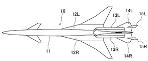
- FIG. 1 is a plan view showing the appearance of a supersonic aircraft according to an embodiment of the present invention
- FIG. 2 is a side view thereof
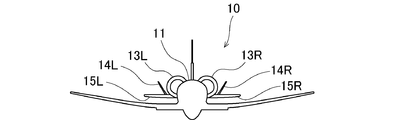
- FIG. 3 is a front view thereof.
- the fuselage 11 of the fuselage 10 is provided with a pair of main wings 12R and 12L, a pair of engine nacelles 13R and 13L, and a pair of horizontal tails 14R and 14L. Fins 15R and 15L are provided on the pair of horizontal tails 14R and 14L, respectively.
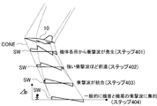
- a shock wave SW is generated from each part of the airframe 10 as shown in FIG. 4 (step 401).
- a wave with a large pressure fluctuation propagates faster in the atmosphere (step 402) and is integrated into two strong shock waves SW, the nose and the tail (step 403), Is observed as an N-type pressure wave with a large pressure rise of 2 degrees (step 404).
- the shock wave SW generated and propagated by the supersonic machine propagates in a cone-shaped CONE and reaches the ground.
- the cone-shaped CONE is sometimes called a Mach cone.
- the shock wave SW reached on the ground is observed as a sonic boom.
- the present invention reduces the sonic boom by devising the shape of the fuselage 10.
- FIG. 6 is a flowchart showing a method for designing the shape of a supersonic aircraft according to an embodiment of the present invention. The first embodiment will be described along the following flowchart.
- ⁇ Setting of initial shape and target equivalent sectional area (step 601)>
- equivalent cross-sectional area it means the sum of volume equivalent cross-sectional area and lift equivalent cross-sectional area.
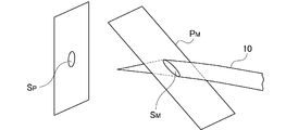
- the equivalent cross-sectional area of the supersonic aircraft as shown in FIG. 7, the aircraft 10 to the body axis direction of the cross-sectional area S M cut Mach plane P M that is determined by the number of cruise Mach supersonic is that of the distribution of the projected area S P output.
- the Mach plane P M, the angle ⁇ sin-1 (1 / M) tilted plane normal vector with respect to body axes.
- the cross-sectional area S M coincides with a value obtained by multiplying the projected area SP by the cruise Mach number M due to a geometric relationship.
- FIG. 8 is a diagram showing an initial shape of the supersonic aircraft in this embodiment. This figure is the figure which looked down at the airframe 10 from diagonally downward. A region indicated by diagonal lines is a region whose shape is optimized as will be described later.
- FIG. 9 is a graph showing the target equivalent cross-sectional area. In this embodiment, the target equivalent sectional area is determined empirically so that the sonic boom can be reduced based on the equivalent sectional area of the initial shape.
- the representative example is illustrated by the patent document 1 and the nonpatent literature 2. FIG. The descriptions of these documents are included in the disclosure of this specification.
- Step 602 the near-field pressure waveform is evaluated.
- a near-field pressure waveform is estimated for the initial shape of the airframe 10 when it is assumed that the supersonic aircraft flew at the cruising speed.
- the cruise speed of the supersonic aircraft is, for example, Mach 1.6.
- the near field is a position immediately below the body 10 and close to the body 10. For example, when the length of the body 10 is 1, the position is 0.3 below the body 10.
- the near-field pressure waveform for the initial shape can typically be obtained by a wind tunnel model test or a numerical calculation model.
- FIG. 10 shows the near-field pressure waveform for the initial shape obtained by the numerical calculation model.
- step 603 the equivalent cross-sectional area of the airframe 10 is evaluated from the near-field pressure waveform with respect to the initial shape shown in FIG.
- the equivalent cross-sectional area was evaluated using the following formula.
- FIG. 11 shows an equivalent cross-sectional area obtained from the near-field waveform with respect to the initial shape.
- step 604 a Mach plane corresponding to the cruising speed (Mach 1.6) of the supersonic aircraft is set, so that the equivalent cross-sectional area shown in FIG. 11 approaches the target equivalent cross-sectional area shown in FIG.
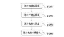
- a design curve corresponding to an initial curve at which the initial shape intersects the Mach plane is set on the Mach plane. In this embodiment, as shown in FIG. 12, four steps are taken.
- FIG. 13 is a graph comparing the initial equivalent cross-sectional area with the target equivalent cross-sectional area shown in FIG. From the figure, it can be seen that there is a section in which there is a large difference between the equivalent cross-sectional area and the target equivalent cross-sectional area.
- the point of this embodiment is that the shape of the section is designed so that the equivalent sectional area is close to the target equivalent sectional area with high accuracy, and that the design can be performed by simple processing.
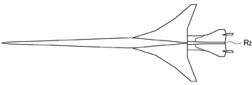
- the design range is set according to the section of the axle where the equivalent sectional area and the target equivalent sectional area are greatly different. Specifically, cut by Mach plane passing through the start and end points of the interval I of shaft respectively (FIG. 14 (a)), the design range R 1 a region where the Mach plane is sandwiched by a line which corresponds to the lower surface of the fuselage 10 (FIG. 14B).
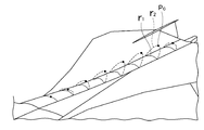
- Design plane setting (step 1202) As shown in FIGS. 17 and 18, a plurality of Mach planes, for example, eight Mach planes P M (design planes) that intersect with the lower surface of the rear part of the fuselage of the initial shape are set, and a curve is designed on these Mach planes P M. To do. R 1 shown in FIG. 18 shows a curve and rear fuselage underside of the Mach plane P M and the initial geometry intersects.
- the design plane is a plane that is not parallel to the Mach plane (Non-Patent Documents 5 and 6), but the Mach plane is a design plane in this embodiment.
- Design variable setting (step 1203) As shown in FIG. 19, the midpoint of the design curve r 2 on each of the eight Mach plane P M as a control point P c, is set to design variables the position of each control point P c.
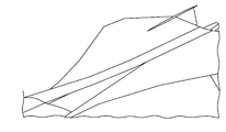
- Design variable optimization (step 1204) As shown in FIG. 20, the area (hatched line in the figure) of the region R 3 surrounded by the initial shape curve r 1 and the design shape curve r 2 is optimized. That is, the area of the region R 3, match the multiplied value of the difference between cruise Mach number of equivalent cross-sectional area in a position corresponding to the design plane. This is shown in the following equation.
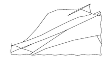
- FIG. 21 shows the initial shape of the lower back of the fuselage
- FIG. 22 shows the design shape.
- step 606 the ground waveform is evaluated.
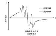
- FIG. 23 shows approximate field waveforms of the initial shape and the design shape in this embodiment.
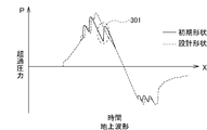
- FIG. 24 is a graph showing the ground waveform of the initial shape and the design shape. In this embodiment, as shown in FIG. 24, it can be seen that the waveform portion corresponding to the rear end boom of the ground waveform is optimized and the sonic boom noise level is improved. In this example, since the change in the lift equivalent cross-sectional area can be ignored, it was possible to design without repetition (one design). In a region where the change in lift equivalent cross-sectional area cannot be ignored, step 604 may be repeated until accuracy is obtained.
- the input / output relationship is a simple one-to-one system. Because of the one-to-one correspondence, a more precise design that considers even first-order differentiation is possible, and the design accuracy is improved. Since it is a simple system, the number of repetitions of the process of matching the equivalent cross-sectional area of the design shape with the target equivalent cross-sectional area is reduced, and the design time is shortened. In particular, if the change in lift equivalent cross sectional area is negligible, the equivalent cross sectional area can be matched to the target equivalent cross sectional area without repeating the process.
- the Mach plane is a design plane
- the change in volume equivalent cross-sectional area with respect to the change in two-dimensional cross section is a simple one-to-one correspondence. More precise design becomes possible, and the design is completed in a shorter period of time.
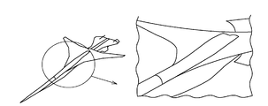
- FIG. 26 is a bird's-eye view of the initial-shaped aircraft according to the second embodiment as seen obliquely from below.
- FIG. 27 is a bird's-eye view of the aircraft with the designed shape as seen from obliquely below.
- the design shape was obtained by the design method according to the flowchart of FIG.
- the local pressure increase in the near-field waveform middle vicinity 291 and the ground waveform middle vicinity 301 is eliminated, and the sonic boom noise level is improved.
- a precise design requiring control up to the first derivative of the equivalent cross-sectional area was achieved.
- the present invention is not limited to the above-described embodiment, and various modifications and applications can be made within the scope of the technical idea.
- the scope of its implementation also belongs to the technical scope of the present invention.
- the design shape according to the present invention is obtained for a part of the fuselage.
- the shape is not limited to this, and the entire fuselage may be used, or only the main wing, or the fuselage and the main wing may be used.
- the present invention can be applied to places.
- the shape of the supersonic aircraft based on the design method of the present invention has a remarkable effect of reducing the sonic boom, and is different from the conventional shape in that respect and can be distinguished. That is, the initial shape of the aircraft and the target equivalent cross-sectional area of the aircraft were set, and the near-field pressure waveform with respect to the initial shape of the aircraft was estimated when the supersonic aircraft flew at the cruise speed, and the estimated Evaluating the equivalent cross-sectional area from the near-field pressure waveform with respect to the initial shape of the airframe, setting a Mach plane corresponding to the cruise speed for the portion, and so that the equivalent cross-sectional area approaches the target equivalent cross-sectional area
- the shape of the fuselage with the design curve corresponding to the initial curve where the initial shape intersects the Mach plane is set on the Mach plane is a new shape that has not existed before, and the shape can be obtained with a simple design process, In addition, the sonic boom can be reduced.
Landscapes
- Engineering & Computer Science (AREA)
- Physics & Mathematics (AREA)
- Aviation & Aerospace Engineering (AREA)
- Geometry (AREA)
- General Physics & Mathematics (AREA)
- Manufacturing & Machinery (AREA)
- Theoretical Computer Science (AREA)
- Automation & Control Theory (AREA)
- Transportation (AREA)
- Computational Mathematics (AREA)
- Mathematical Analysis (AREA)
- Mathematical Optimization (AREA)
- Pure & Applied Mathematics (AREA)
- Computer Hardware Design (AREA)
- Evolutionary Computation (AREA)
- General Engineering & Computer Science (AREA)
- Aerodynamic Tests, Hydrodynamic Tests, Wind Tunnels, And Water Tanks (AREA)
Abstract
Description
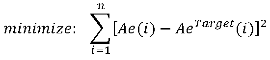
i:機軸方向の離散点
Ae(i):機軸方向の位置i点での等価断面積
AeTarget(i):機軸方向の位置i点での目標等価断面積
そのプロセスにおいて、設計時間と設計確度が課題となる。設計時間に関して、設計形状の等価断面積を目標等価断面積に一致させるプロセスの繰返し回数を減らすことが課題である。設計確度に関して、設計形状の等価断面積と目標等価断面積の一致に加えて、それらの一階微分の一致ないし整合が課題であると、本発明者らの検討結果から示唆される(非特許文献4)。

前記設計曲線をマッハ平面上に設定するステップでは、前記マッハ平面の前記設計曲線の中間点を制御点とし、前記制御点の位置を設計変数と設定し、前記面積を前記乗算した値と一致させるように、前記制御点を最適化してもよい。

Ae(x):機軸方向の位置x点での等価断面積
r:機体から近傍場までの距離
M:巡航マッハ数
γ:空気の比熱比
Δp/p:近傍場圧力
x0:近傍場圧力開始点
本発明の一形態に係る超音速機の生産方法は、上記に記載の超音速機の機体形状の設計方法を用いて超音速機を設計し、設計結果に基づく機体形状の超音速機を製作する。
ようにこの実施形態に係る超音速機は、機体10の胴体11に一対の主翼12R、12L、一対のエンジンナセル13R、13Lと、一対の水平尾翼14R、14Lが設けられている。一対の水平尾翼14R、14L上には、それぞれフィン15R、15Lが設けられている。
本発明は、機体10の形状を工夫することによりソニックブームを低減するものである。
本実施形態において、単に"等価断面積"と言う場合、それは体積等価断面積と揚力等価断面積の和を指す。ここで、超音速機の等価断面積とは、図7に示すように、機体10を超音速機の巡航マッハ数で決定されるマッハ平面PMで切断した断面積SMの機体軸方向への投影面積SPの分布のことである。マッハ平面PMとは、法線ベクトルを機体軸に対して角度μ=sin-1(1/M)傾けた平面である。なお、幾何学的関係により、前記断面積SMは前記投影面積SPに巡航マッハ数Mを乗算した値と一致する。
図8はこの実施形態における超音速機の初期形状を示す図である。この図は機体10を斜め下から俯瞰した図である。斜線で示される領域は後に説明するが形状を最適化する領域である。
図9は目標等価断面積を示すグラフである。この実施形態においては、目標等価断面積は初期形状の等価断面積をもとにしてソニックブームが低減できるように経験的に定めた。なお、ソニックブーム低減化の等価断面積については、特許文献1や非特許文献2に代表例が例示されている。これら文献の記載は本明細書の開示に含まれるものである。
ステップ602では、近傍場の圧力波形を評価する。
超音速機が巡航速度で飛行したと仮定したときの機体10の初期形状に対する近傍場の圧力波形を推定する。
ここで、超音速機が巡航速度とは、例えばMach1.6である。
近傍場とは、機体10の直下で機体10に近い位置であり、例えば機体10の長さを1としたとき、機体10より0.3だけ下にある位置である。
初期形状に対する近傍場の圧力波形は、典型的には、風洞模型試験や数値計算モデルによって取得できる。
図10に数値計算モデルによって取得された初期形状に対する近傍場の圧力波形を示す。
ステップ603では、図10に示した初期形状に対する近傍場の圧力波形から機体10の等価断面積を評価する。
本実施形態では、下記の式を使って等価断面積を評価した。

Ae(x):近傍場x点での等価断面積
r:機体から近傍場までの距離
M:巡航マッハ数
γ:空気の比熱比
Δp/p:近傍場圧力
x0:近傍場圧力開始点
図11に初期形状に対する近傍場波形から得られた等価断面積を示す。
ステップ604では、当該超音速機の巡航速度(Mach1.6)に応じたマッハ平面を設定し、図11に示した等価断面積が図9に示した目標等価断面積に近づくように、機体10の初期形状とマッハ平面とが交差する初期曲線に対応する設計曲線をマッハ平面上に設定する。この実施形態においては、図12に示すように、4つのステップを踏む。
・設計範囲の設定(ステップ1201)
図13は初期形状の等価断面積と図9に示した目標等価断面積とを比較したグラフである。同図より、等価断面積と目標等価断面積とは大きく相違がみられる区間が存在することが分かる。この相違する区間において、等価断面積が目標等価断面積に精度よく近づけるように当該区間の形状を設計する点、及びその設計を簡単な処理で行える点が本実施形態のポイントである。
図14に示した設計範囲R1には、胴体、主翼、ナセル、尾翼などが含まれるが、典型的な例としては図15及び図16に示すように、胴体の後部下面に設計範囲を絞る(R2)。
図17及び図18に示すように、初期形状の胴体後部下面と交差する複数のマッハ平面、例えば8つのマッハ平面PM(設計平面)を設定し、これらのマッハ平面PM上で曲線を設計する。図18に示すr1はマッハ平面PMと初期形状の胴体後部下面とが交差する曲線を示している。
すなわち、従来はマッハ平面と平行でない平面を設計平面としていた(非特許文献5及び6)のに対して、本実施形態ではマッハ平面を設計平面としている点が異なる。
図19に示すように、8つの各マッハ平面PM上の設計曲線r2の中間点を制御点Pcとし、各制御点Pcの位置を設計変数と設定する。
図20に示すように、初期形状の曲線r1と設計形状の曲線r2で囲まれる領域R3の面積(図中斜線)を最適化する。すなわち、領域R3の面積を、その設計平面に対応する位置での等価断面積の差分と巡航マッハ数との乗算値に一致させる。このことを下記の式に示す。
ここで、ΔA:目標等価断面積と初期形状の等価断面積との差分
Mach:巡航マッハ数
図21に胴体後部下面の初期形状を示し、図22にその設計形状を示す。
ステップ606において、地上波形を評価する。
図23にこの実施形態における初期形状と設計形状の近似場波形を示す。また、図24にその初期形状と設計形状の地上波形を示すグラフである。
この実施形態では、図24に示すように、地上波形の後端ブームに相当する波形部分が最適化され、ソニックブーム騒音レベルが改善したことが分かる。また、この例では、揚力等価断面積の変化が無視できる領域なので、繰返しなしで(一回の設計)で設計できた。揚力等価断面積の変化が無視できない領域の場合には、精度が得られるまでステップ604を繰り返えせばよい。
先行技術の実施形態では、図25に示すように、機軸に垂直な平面上で定義された二次元断面の断面積を変化させたときに、体積等価断面積は 区間t1<x<t2 で変化してしまう。つまり、二次元断面の変化を"入力"、体積等価断面積の変化を"出力"と考えたときに、入出力の関係が一対一ではない複雑な系である。
本実施形態では、マッハ平面上で定義された二次元断面の断面積を変化させたときに、体積等価断面積は同一位置x=tのみで変化する。つまり、入出力の関係が一対一の単純な系となる。一対一対応のために、一階微分までを考慮したより緻密な設計が可能となり設計確度が向上する。単純な系であるために、設計形状の等価断面積を目標等価断面積に一致させるプロセスの繰返し回数が減り、設計時間が短縮される。特に、揚力等価断面積の変化が無視できる場合には、プロセスの繰返しなしで等価断面積を目標等価断面積に一致させることができる。
図26は第2の実施形態に係る初期形状の機体を斜め下からみた俯瞰図である。図27はその設計形状の機体を斜め下からみた俯瞰図である。
この実施形態では、図28に示すように、機体10の中部下面の局所的な区間I'について図6のフローチャートに従った設計手法により設計形状を得た。
この実施形態では、図29及び図30に示すように、近傍場波形中間付近291及び地上波形中間付近301の局所的な圧力上昇がなくなり、ソニックブーム騒音レベルが改善した。そして、等価断面積の一階微分までの制御を要する緻密な設計ができた。
本発明は上記の実施形態には限定されずその技術思想の範囲内で様々な変形や応用による実施が可能である。その実施の範囲も本発明の技術的範囲に属する。
例えば、上記の実施形態では、胴体の一部について本発明による設計形状を得ていたが、これに限らず、胴体全体であってもよく、あるいは主翼のみ、あるいは胴体と主翼など、機体のあらゆる個所に本発明を適用することができる。
PM :マッハ平面
Pc :制御点
SM :断面積
r2 :設計曲線
Claims (9)
- 超音速機の機体の形状を設計する方法であって、
前記機体の初期形状及び前記機体の目標等価断面積を設定し、
前記超音速機が巡航速度で飛行したと仮定したときの前記機体の初期形状に対する近傍場圧力波形を推定し、
前記推定した機体の初期形状に対する近傍場圧力波形から等価断面積を評価し、
前記巡航速度に応じたマッハ平面を設定し、前記等価断面積が前記目標等価断面積に近づくように、前記機体の初期形状と前記マッハ平面とが交差する初期曲線に対応する設計曲線を前記マッハ平面上に設定する
超音速機の機体形状の設計方法。 - 請求項1に記載の超音速機の機体形状の設計方法であって、
前記設計曲線をマッハ平面上に設定するステップでは、前記マッハ平面上で前記初期曲線及び前記設計曲線により囲まれた領域の面積を、前記領域に対応する位置での前記目標等価断面積と前記等価断面積との差分に前記巡航速度に応じた巡航マッハ数を乗算した値と一致させることで、前記設計曲線を前記マッハ平面上に設定する
超音速機の機体形状の設計方法。 - 請求項2に記載の超音速機の機体形状の設計方法であって、
前記設計曲線をマッハ平面上に設定するステップでは、前記マッハ平面の前記設計曲線の中間点を制御点とし、前記制御点の位置を設計変数と設定し、前記面積を前記乗算した値と一致させるように、前記制御点を最適化する
超音速機の機体形状の設計方法。 - 請求項1乃至3のうちいずれか一項に記載の超音速機の機体形状の設計方法であって、
前記機体の初期形状及び前記機体の目標等価断面積を設定するステップでは、前記目標等価断面積を初期形状の等価断面積に基づき設定する
超音速機の機体形状の設計方法。 - 請求項1乃至4のうちいずれか一項に記載の超音速機の機体形状の設計方法であって、
前記設計曲線をマッハ平面上に設定するステップの後に、
前記超音速機が巡航速度で飛行したと仮定したときの前記機体の前記設計曲線に応じた形状に対する近傍場圧力波形を推定し、
前記推定した機体の前記設計曲線に応じた形状に対する近傍場圧力波形から等価断面積を評価し、
前記巡航速度に応じたマッハ平面を設定し、前記等価断面積が前記目標等価断面積に近づくように、前記機体の前記設計曲線に応じた形状と前記マッハ平面とが交差する曲線に対応する設計曲線を前記マッハ平面上に再設定する
超音速機の機体形状の設計方法。 - 請求項1乃至5のうちいずれか一項に記載の超音速機の機体形状の設計方法であって、
前記近傍場圧力波形を推定するステップでは、風洞試験又は数値計算により前記近傍場圧力波形を推定する
超音速機の機体形状の設計方法。 - 請求項1乃至5のうちいずれか一項に記載の超音速機の機体形状の設計方法であって、
前記等価断面積を評価するステップでは、下記式に基づき前記等価断面積を評価する
超音速機の機体形状の設計方法。
ここで、
Ae(x):近傍場x点での等価断面積
r:機体から近傍場までの距離
M:巡航マッハ数
γ:空気の比熱比
Δp/p:近傍場圧力
x0:近傍場圧力開始点 - 請求項1乃至7に記載の超音速機の機体形状の設計方法を用いて超音速機を設計し、
設計結果に基づく機体形状の超音速機を製作する
超音速機の生産方法。 - 超音速機の機体の少なくとも一部の形状について、
機体の初期形状及び前記機体の目標等価断面積を設定し、
前記超音速機が巡航速度で飛行したと仮定したときの前記機体の初期形状に対する近傍場圧力波形を推定し、
前記推定した機体の初期形状に対する近傍場圧力波形から等価断面積を評価し、
前記部分について、前記巡航速度に応じたマッハ平面を設定し、前記等価断面積が前記目標等価断面積に近づくように、前記機体の初期形状と前記マッハ平面とが交差する初期曲線に対応する設計曲線を前記マッハ平面上に設定した
機体の形状を有する超音速機。
Priority Applications (3)
| Application Number | Priority Date | Filing Date | Title |
|---|---|---|---|
| EP19775252.0A EP3778389B1 (en) | 2018-03-29 | 2019-02-21 | Method for designing shape of fuselage of supersonic aircraft, supersonic aircraft production method, and supersonic aircraft |
| JP2020510433A JP7076156B2 (ja) | 2018-03-29 | 2019-02-21 | 超音速機の機体形状の設計方法、超音速機の生産方法 |
| US17/042,720 US12017800B2 (en) | 2018-03-29 | 2019-02-21 | Method of designing a shape of an airframe of a supersonic aircraft, production method of a supersonic aircraft, and supersonic aircraft |
Applications Claiming Priority (2)
| Application Number | Priority Date | Filing Date | Title |
|---|---|---|---|
| JP2018-064900 | 2018-03-29 | ||
| JP2018064900 | 2018-03-29 |
Publications (1)
| Publication Number | Publication Date |
|---|---|
| WO2019187828A1 true WO2019187828A1 (ja) | 2019-10-03 |
Family
ID=68059792
Family Applications (1)
| Application Number | Title | Priority Date | Filing Date |
|---|---|---|---|
| PCT/JP2019/006509 Ceased WO2019187828A1 (ja) | 2018-03-29 | 2019-02-21 | 超音速機の機体形状の設計方法、超音速機の生産方法及び超音速機 |
Country Status (4)
| Country | Link |
|---|---|
| US (1) | US12017800B2 (ja) |
| EP (1) | EP3778389B1 (ja) |
| JP (1) | JP7076156B2 (ja) |
| WO (1) | WO2019187828A1 (ja) |
Cited By (4)
| Publication number | Priority date | Publication date | Assignee | Title |
|---|---|---|---|---|
| US20210016900A1 (en) * | 2018-03-29 | 2021-01-21 | Japan Aerospace Exploration Agency | Method of designing a shape of an airframe of a supersonic aircraft, production method of a supersonic aircraft, and supersonic aircraft |
| CN112380786A (zh) * | 2020-10-30 | 2021-02-19 | 中国运载火箭技术研究院 | 空气舵热环境建模方法、设备及存储介质 |
| JPWO2021186940A1 (ja) * | 2020-03-16 | 2021-09-23 | ||
| CN114524110A (zh) * | 2022-03-30 | 2022-05-24 | 西北工业大学 | 一种针对超声速民机的旋成体静音锥快速设计方法 |
Families Citing this family (4)
| Publication number | Priority date | Publication date | Assignee | Title |
|---|---|---|---|---|
| CN112797856B (zh) * | 2021-01-30 | 2023-01-03 | 中国民航大学 | 运输类飞机最小风险炸弹位置载荷快速评估方法 |
| CN113946904B (zh) * | 2021-08-31 | 2024-06-11 | 中国航天空气动力技术研究院 | 一种大尺寸低噪声喷管设计方法 |
| CN114756969B (zh) * | 2022-04-20 | 2024-06-11 | 北京航空航天大学 | 一种飞机容积和表面积计算系统及方法 |
| CN120024504A (zh) * | 2025-01-23 | 2025-05-23 | 西北工业大学 | 一种超声速民机低声爆概念布局综合设计方法 |
Citations (4)
| Publication number | Priority date | Publication date | Assignee | Title |
|---|---|---|---|---|
| US20050116107A1 (en) * | 2003-11-11 | 2005-06-02 | Supersonic Aerospace International, Llc | Area ruling for vertical stabilizers |
| US20050116108A1 (en) * | 2003-11-14 | 2005-06-02 | Supersonic Aerospace International, Llc | System, apparatus, and method for redistributing forces to meet performance goals and shock wave disturbance constraints |
| JP5057374B2 (ja) | 2007-07-06 | 2012-10-24 | 独立行政法人 宇宙航空研究開発機構 | 後端ソニックブーム低減化のための超音速航空機形状 |
| US20150108269A1 (en) * | 2012-12-07 | 2015-04-23 | Richard H. Lugg | Hypersonic aircraft |
Family Cites Families (14)
| Publication number | Priority date | Publication date | Assignee | Title |
|---|---|---|---|---|
| PL351779A1 (en) * | 2002-01-18 | 2003-07-28 | Advanced Digital Broadcast Ltd | Apparatus for storing data and method of subdividing te data storage area |
| US7546977B2 (en) * | 2003-07-03 | 2009-06-16 | Lockheed-Martin Corporation | Passive aerodynamic sonic boom suppression for supersonic aircraft |
| WO2005047102A2 (en) | 2003-11-11 | 2005-05-26 | Supersonic Aerospace International Llc | Systems and methods for configuring aircraft to meet performance goals and shock wave disturbance constraints |
| US6942178B2 (en) * | 2003-11-11 | 2005-09-13 | Supersonic Aerospace International, Llc | Mach weighted area ruling for supersonic vehicles |
| JP3855064B2 (ja) * | 2003-12-18 | 2006-12-06 | 独立行政法人 宇宙航空研究開発機構 | 超音速航空機の胴体形状の決定方法および胴体前胴部形状 |
| JP4171913B2 (ja) * | 2004-04-13 | 2008-10-29 | 独立行政法人 宇宙航空研究開発機構 | 低ブーム特性と低抵抗特性を両立する可変前進翼超音速航空機 |
| US7252263B1 (en) * | 2004-07-29 | 2007-08-07 | Hawker Beechcraft Corporation | Design methods and configurations for supersonic aircraft |
| US20060038063A1 (en) * | 2004-08-18 | 2006-02-23 | Northrop Grumman Corporation | Shaped sonic boom aircraft |
| US20080105783A1 (en) * | 2006-11-03 | 2008-05-08 | Cessna Aircraft Company | Fuselage design for sonic boom suppression of supersonic aircraft |
| US8403256B1 (en) * | 2009-03-25 | 2013-03-26 | The Boeing Company | Swept-wing powered-lift aircraft |
| RU2440916C1 (ru) * | 2010-07-28 | 2012-01-27 | Открытое акционерное общество "ОКБ Сухого" | Самолет интегральной аэродинамической компоновки |
| JP5747343B2 (ja) * | 2010-12-14 | 2015-07-15 | 国立研究開発法人宇宙航空研究開発機構 | 超音速航空機の実機相当レイノルズ数における自然層流翼の設計方法 |
| US11325700B2 (en) * | 2017-07-21 | 2022-05-10 | The Government Of The United States Of America, As Represented By The Secretary Of The Navy | Hypersonic waverider stream surface actuation for variable design point operation |
| JP7076156B2 (ja) * | 2018-03-29 | 2022-05-27 | 国立研究開発法人宇宙航空研究開発機構 | 超音速機の機体形状の設計方法、超音速機の生産方法 |
-
2019
- 2019-02-21 JP JP2020510433A patent/JP7076156B2/ja active Active
- 2019-02-21 WO PCT/JP2019/006509 patent/WO2019187828A1/ja not_active Ceased
- 2019-02-21 US US17/042,720 patent/US12017800B2/en active Active
- 2019-02-21 EP EP19775252.0A patent/EP3778389B1/en active Active
Patent Citations (4)
| Publication number | Priority date | Publication date | Assignee | Title |
|---|---|---|---|---|
| US20050116107A1 (en) * | 2003-11-11 | 2005-06-02 | Supersonic Aerospace International, Llc | Area ruling for vertical stabilizers |
| US20050116108A1 (en) * | 2003-11-14 | 2005-06-02 | Supersonic Aerospace International, Llc | System, apparatus, and method for redistributing forces to meet performance goals and shock wave disturbance constraints |
| JP5057374B2 (ja) | 2007-07-06 | 2012-10-24 | 独立行政法人 宇宙航空研究開発機構 | 後端ソニックブーム低減化のための超音速航空機形状 |
| US20150108269A1 (en) * | 2012-12-07 | 2015-04-23 | Richard H. Lugg | Hypersonic aircraft |
Non-Patent Citations (8)
| Title |
|---|
| BARGER, R.L.: "Fuselage Design for a Specified Mach-Sliced Area Distribution", NASA-TP-2975, 1990 |
| DARDEN, C.: "Sonic Boom Minimization With Nose-Bluntness Relaxation", NASA TP-1348, 1979 |
| LI, W. ET AL.: "Inverse design of low- boom supersonic concepts using reversed equivalent-area targets", JOURNAL OF AIRCRAFT, vol. 51, no. 1, 2014, pages 29 - 36, XP009523830, ISSN: 0021-8669, DOI: 10.2514/1.C031551 * |
| LI, W.RALLABHANDI, S.: "Inverse Design of Low-Boom Supersonic Concepts Using Reversed Equivalent-Area Targets", JOURNAL OF AIRCRAFT, vol. 51, no. 1, 2014, pages 29 - 36, XP009523830, DOI: 10.2514/1.C031551 |
| See also references of EP3778389A4 |
| SEEBASS, R.GEORGE, A.: "Sonic-Boom Minimization", JOURNAL OF THE ACOUSTICAL SOCIETY OF AMERICA, vol. 51, no. 2, 1972, pages 686 - 694, XP002367687, DOI: 10.1121/1.1912902 |
| TATSUNORI YUHARAATSHUSHI UENOYOSHIKAZU MAKINO: "urvature distribution of equivalent cross-sectional area for purpose of reducing rear end boom", THE JAPAN SOCIETY FOR AERONAUTICAL AND SPACE SCIENCES, 55TH AIRCRAFT SYMPOSIUM, 3A09, SHIMANE CIVIC CENTER, 2017 |
| WINTZER, M. ET AL.: "Under-Track CFD-Based Shape Optimization for a Low-Boom Demonstrator Concept", AIAA 2015-2260, 2015 |
Cited By (10)
| Publication number | Priority date | Publication date | Assignee | Title |
|---|---|---|---|---|
| US20210016900A1 (en) * | 2018-03-29 | 2021-01-21 | Japan Aerospace Exploration Agency | Method of designing a shape of an airframe of a supersonic aircraft, production method of a supersonic aircraft, and supersonic aircraft |
| US12017800B2 (en) * | 2018-03-29 | 2024-06-25 | Japan Aerospace Exploration Agency | Method of designing a shape of an airframe of a supersonic aircraft, production method of a supersonic aircraft, and supersonic aircraft |
| JPWO2021186940A1 (ja) * | 2020-03-16 | 2021-09-23 | ||
| WO2021186940A1 (ja) | 2020-03-16 | 2021-09-23 | 国立研究開発法人宇宙航空研究開発機構 | 超音速機の機体形状の設計方法、超音速機の生産方法及び超音速機 |
| JP7323964B2 (ja) | 2020-03-16 | 2023-08-09 | 国立研究開発法人宇宙航空研究開発機構 | 超音速機の機体形状の設計方法、超音速機の生産方法及び超音速機 |
| EP4122819A4 (en) * | 2020-03-16 | 2024-03-13 | Japan Aerospace Exploration Agency | Method of designing airframe shape of supersonic aircraft, method of producing supersonic aircraft, and supersonic aircraft |
| CN112380786A (zh) * | 2020-10-30 | 2021-02-19 | 中国运载火箭技术研究院 | 空气舵热环境建模方法、设备及存储介质 |
| CN112380786B (zh) * | 2020-10-30 | 2024-04-05 | 中国运载火箭技术研究院 | 空气舵热环境建模方法、设备及存储介质 |
| CN114524110A (zh) * | 2022-03-30 | 2022-05-24 | 西北工业大学 | 一种针对超声速民机的旋成体静音锥快速设计方法 |
| CN114524110B (zh) * | 2022-03-30 | 2023-03-10 | 西北工业大学 | 一种针对超声速民机的旋成体静音锥快速设计方法 |
Also Published As
| Publication number | Publication date |
|---|---|
| EP3778389A4 (en) | 2021-05-19 |
| EP3778389B1 (en) | 2026-02-11 |
| JP7076156B2 (ja) | 2022-05-27 |
| US20210016900A1 (en) | 2021-01-21 |
| JPWO2019187828A1 (ja) | 2021-01-07 |
| US12017800B2 (en) | 2024-06-25 |
| EP3778389A1 (en) | 2021-02-17 |
Similar Documents
| Publication | Publication Date | Title |
|---|---|---|
| JP7076156B2 (ja) | 超音速機の機体形状の設計方法、超音速機の生産方法 | |
| CN116186904A (zh) | 一种具有升力面在流体中运动的机械总体气动布局方法 | |
| US20150108269A1 (en) | Hypersonic aircraft | |
| Kennedy et al. | The application of advanced beamforming techniques for the noise characterization of installed counter rotating open rotors | |
| CN114201819A (zh) | 一种融合声阵列和在桨控制的直升机主动噪声抑制装置 | |
| CN110525680B (zh) | 一种适用于复杂高超声速飞行器机理研究模型简化设计方法 | |
| Ueno et al. | Multi-fidelity low-boom design based on near-field pressure signature | |
| JP2005178491A (ja) | 超音速航空機の胴体形状の決定方法および胴体前胴部形状 | |
| Ueda et al. | Supersonic natural-laminar-flow wing-design concept at high-Reynolds-number conditions | |
| US7546977B2 (en) | Passive aerodynamic sonic boom suppression for supersonic aircraft | |
| CN108170939A (zh) | 一种基于后缘襟翼的降低旋翼噪声的方法及系统 | |
| US11420759B2 (en) | Supersonic aircraft and method of reducing sonic booms | |
| JP7323964B2 (ja) | 超音速機の機体形状の設計方法、超音速機の生産方法及び超音速機 | |
| CN108021772A (zh) | 一种基于射流的降低旋翼噪声的方法及系统 | |
| US6588703B1 (en) | Passive aerodynamic sonic boom suppression for supersonic aircraft | |
| Kim et al. | Mail-slot nacelle shape design for N3-X hybrid wing-body configuration | |
| Ueno et al. | Robust low-boom design in primary boom carpet | |
| CN115618499A (zh) | 一种考虑三维影响的宽速域薄翼型多目标优化设计方法 | |
| Zha et al. | Toward zero sonic-boom and high efficiency supersonic flight, part I: a novel concept of supersonic bi-directional flying wing | |
| JP2009012686A (ja) | 後端ソニックブーム低減化のための超音速航空機形状 | |
| Kornev et al. | Aerodynamic design method of integrated aircraft with submerged intake devices and power plant included into airframe carrying system | |
| CN120270530B (zh) | 基于兼顾后体效应的翼身融合宽速域飞行器布局设计方法 | |
| KR20100078734A (ko) | 항공기 면적곡선 분석 방법 | |
| CN105589995B (zh) | 一种超声速飞行器低音爆气动布局优化方法 | |
| Pankratov et al. | Acoustic tests of contra rotating propellers in the" Dream" project. |
Legal Events
| Date | Code | Title | Description |
|---|---|---|---|
| 121 | Ep: the epo has been informed by wipo that ep was designated in this application |
Ref document number: 19775252 Country of ref document: EP Kind code of ref document: A1 |
|
| ENP | Entry into the national phase |
Ref document number: 2020510433 Country of ref document: JP Kind code of ref document: A |
|
| NENP | Non-entry into the national phase |
Ref country code: DE |
|
| WWE | Wipo information: entry into national phase |
Ref document number: 2019775252 Country of ref document: EP |
|
| ENP | Entry into the national phase |
Ref document number: 2019775252 Country of ref document: EP Effective date: 20201029 |
|
| WWG | Wipo information: grant in national office |
Ref document number: 2019775252 Country of ref document: EP |