WO2019186932A1 - 電池及び電池パック - Google Patents
電池及び電池パック Download PDFInfo
- Publication number
- WO2019186932A1 WO2019186932A1 PCT/JP2018/013376 JP2018013376W WO2019186932A1 WO 2019186932 A1 WO2019186932 A1 WO 2019186932A1 JP 2018013376 W JP2018013376 W JP 2018013376W WO 2019186932 A1 WO2019186932 A1 WO 2019186932A1
- Authority
- WO
- WIPO (PCT)
- Prior art keywords
- negative electrode
- exterior
- positive electrode
- battery
- current collecting
- Prior art date
Links
Images


Classifications
-
- H—ELECTRICITY
- H01—ELECTRIC ELEMENTS
- H01M—PROCESSES OR MEANS, e.g. BATTERIES, FOR THE DIRECT CONVERSION OF CHEMICAL ENERGY INTO ELECTRICAL ENERGY
- H01M50/00—Constructional details or processes of manufacture of the non-active parts of electrochemical cells other than fuel cells, e.g. hybrid cells
- H01M50/50—Current conducting connections for cells or batteries
-
- H—ELECTRICITY
- H01—ELECTRIC ELEMENTS
- H01M—PROCESSES OR MEANS, e.g. BATTERIES, FOR THE DIRECT CONVERSION OF CHEMICAL ENERGY INTO ELECTRICAL ENERGY
- H01M50/00—Constructional details or processes of manufacture of the non-active parts of electrochemical cells other than fuel cells, e.g. hybrid cells
- H01M50/10—Primary casings, jackets or wrappings of a single cell or a single battery
- H01M50/102—Primary casings, jackets or wrappings of a single cell or a single battery characterised by their shape or physical structure
- H01M50/103—Primary casings, jackets or wrappings of a single cell or a single battery characterised by their shape or physical structure prismatic or rectangular
-
- H—ELECTRICITY
- H01—ELECTRIC ELEMENTS
- H01M—PROCESSES OR MEANS, e.g. BATTERIES, FOR THE DIRECT CONVERSION OF CHEMICAL ENERGY INTO ELECTRICAL ENERGY
- H01M50/00—Constructional details or processes of manufacture of the non-active parts of electrochemical cells other than fuel cells, e.g. hybrid cells
- H01M50/10—Primary casings, jackets or wrappings of a single cell or a single battery
- H01M50/172—Arrangements of electric connectors penetrating the casing
- H01M50/174—Arrangements of electric connectors penetrating the casing adapted for the shape of the cells
- H01M50/176—Arrangements of electric connectors penetrating the casing adapted for the shape of the cells for prismatic or rectangular cells
-
- H—ELECTRICITY
- H01—ELECTRIC ELEMENTS
- H01M—PROCESSES OR MEANS, e.g. BATTERIES, FOR THE DIRECT CONVERSION OF CHEMICAL ENERGY INTO ELECTRICAL ENERGY
- H01M50/00—Constructional details or processes of manufacture of the non-active parts of electrochemical cells other than fuel cells, e.g. hybrid cells
- H01M50/20—Mountings; Secondary casings or frames; Racks, modules or packs; Suspension devices; Shock absorbers; Transport or carrying devices; Holders
- H01M50/204—Racks, modules or packs for multiple batteries or multiple cells
- H01M50/207—Racks, modules or packs for multiple batteries or multiple cells characterised by their shape
- H01M50/209—Racks, modules or packs for multiple batteries or multiple cells characterised by their shape adapted for prismatic or rectangular cells
-
- H—ELECTRICITY
- H01—ELECTRIC ELEMENTS
- H01M—PROCESSES OR MEANS, e.g. BATTERIES, FOR THE DIRECT CONVERSION OF CHEMICAL ENERGY INTO ELECTRICAL ENERGY
- H01M50/00—Constructional details or processes of manufacture of the non-active parts of electrochemical cells other than fuel cells, e.g. hybrid cells
- H01M50/50—Current conducting connections for cells or batteries
- H01M50/543—Terminals
- H01M50/547—Terminals characterised by the disposition of the terminals on the cells
- H01M50/548—Terminals characterised by the disposition of the terminals on the cells on opposite sides of the cell
-
- H—ELECTRICITY
- H01—ELECTRIC ELEMENTS
- H01M—PROCESSES OR MEANS, e.g. BATTERIES, FOR THE DIRECT CONVERSION OF CHEMICAL ENERGY INTO ELECTRICAL ENERGY
- H01M50/00—Constructional details or processes of manufacture of the non-active parts of electrochemical cells other than fuel cells, e.g. hybrid cells
- H01M50/50—Current conducting connections for cells or batteries
- H01M50/543—Terminals
- H01M50/552—Terminals characterised by their shape
- H01M50/553—Terminals adapted for prismatic, pouch or rectangular cells
-
- H—ELECTRICITY
- H01—ELECTRIC ELEMENTS
- H01M—PROCESSES OR MEANS, e.g. BATTERIES, FOR THE DIRECT CONVERSION OF CHEMICAL ENERGY INTO ELECTRICAL ENERGY
- H01M50/00—Constructional details or processes of manufacture of the non-active parts of electrochemical cells other than fuel cells, e.g. hybrid cells
- H01M50/50—Current conducting connections for cells or batteries
- H01M50/543—Terminals
- H01M50/562—Terminals characterised by the material
-
- Y—GENERAL TAGGING OF NEW TECHNOLOGICAL DEVELOPMENTS; GENERAL TAGGING OF CROSS-SECTIONAL TECHNOLOGIES SPANNING OVER SEVERAL SECTIONS OF THE IPC; TECHNICAL SUBJECTS COVERED BY FORMER USPC CROSS-REFERENCE ART COLLECTIONS [XRACs] AND DIGESTS
- Y02—TECHNOLOGIES OR APPLICATIONS FOR MITIGATION OR ADAPTATION AGAINST CLIMATE CHANGE
- Y02E—REDUCTION OF GREENHOUSE GAS [GHG] EMISSIONS, RELATED TO ENERGY GENERATION, TRANSMISSION OR DISTRIBUTION
- Y02E60/00—Enabling technologies; Technologies with a potential or indirect contribution to GHG emissions mitigation
- Y02E60/10—Energy storage using batteries
Definitions
- Embodiments of the present invention relate to a battery and a battery pack.
- Batteries such as a primary battery and a secondary battery generally include an electrode group including a positive electrode and a negative electrode, and an exterior member that houses the electrode group.
- an exterior member that can be thinned and improved in flexibility and excellent in reliability and a battery pack that combines the battery have been developed.
- the battery of the present embodiment includes a positive electrode, a positive electrode current collecting tab electrically connected to the positive electrode, a negative electrode, and a negative electrode current collecting tab electrically connected to the negative electrode.
- a rectangular box shape having a flange portion at the opening, and includes two concave portions each having an inclined surface provided on each of the first side facing the first end surface and the second side corresponding to the second end surface.
- the perspective view of the battery which concerns on 1st embodiment The disassembled perspective view of the battery which concerns on 1st embodiment.
- the perspective view of the electrode group which concerns on 1st and 2nd embodiment The perspective view which shows the state which expanded the electrode group which concerns on 1st and 2nd embodiment partially.
- the perspective view of the battery which concerns on 2nd embodiment The perspective view of the battery pack which concerns on 2nd embodiment.
- the perspective view of the battery pack which concerns on 2nd embodiment The partial exploded perspective view of the battery pack which concerns on 2nd embodiment.
- the battery 100 shown in FIG. 1 is a nonaqueous electrolyte battery.
- the battery 100 includes an exterior member 1, an electrode group (not shown), a positive electrode terminal 3, a negative electrode terminal 4, and a non-aqueous electrolyte (not shown).
- FIG. 2 is an exploded perspective view of the battery 100.
- the electrode group 2 is simplified, but a more detailed perspective view of the electrode group 2 is shown in FIG. 3.
- the exterior member 1 includes a first exterior part 5 and a second exterior part 6.
- the 1st exterior part 5 is a square tube container with a bottom, and has the flange part 5b in the opening part 5a.
- the 1st exterior part 5 consists of stainless steel substantially, for example, or consists of nickel plating steel substantially. When the 1st exterior part 5 is made from stainless steel, the 1st exterior part 5 is produced by shallow drawing, for example from a stainless steel plate. As shown in FIGS.
- the first exterior part 5 has a surface having the maximum area, a long side wall and a short side wall connected to the surface, and a short side wall of the first exterior part 5.
- a concave portion projecting inward is provided near the center of the corner connecting the bottom portion, and the bottom of the concave portion is an inclined surface 5d.
- the first exterior portion 5 has a depth shorter than the long side length when the opening 5a is substantially rectangular.
- the more preferable first exterior portion 5 has a depth shorter than the short side length when the opening 5a is substantially rectangular.
- this recess is provided at the end of the short side wall of the first exterior portion 5, and the recess having the negative electrode terminal 4 described later is the same as the first exterior portion. It is provided on a diagonal line with a surface having a maximum area of 5 as a reference.
- the second exterior portion 6 is a rectangular plate substantially made of stainless steel or substantially made of nickel-plated steel.
- the electrode group 2 is housed in a space formed by welding the flange portion 5 b of the first exterior portion 5 to the four sides of the second exterior portion 6.
- resistance seam welding is used. Resistance seam welding can achieve high hermeticity and heat resistance at a lower cost than laser welding.
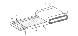
- the electrode group 2 has a flat shape, and includes a positive electrode 7, a negative electrode 8, and a separator 9 disposed between the positive electrode 7 and the negative electrode 8.
- the positive electrode 7 has a strip-shaped positive electrode current collector made of, for example, a foil, and this positive electrode current collector includes a positive electrode current collecting tab 7a having one end parallel to the long side of the positive electrode current collector, and at least a positive electrode current collector. And a positive electrode material layer (positive electrode active material-containing layer) 7b formed on the positive electrode current collector excluding the portion of the tab 7a.
- the negative electrode 8 has a strip-shaped negative electrode current collector made of, for example, a foil, and the negative electrode current collector includes a negative electrode current collecting tab 8a having one end parallel to the long side of the negative electrode current collector, and at least the negative electrode A negative electrode material layer (negative electrode active material-containing layer) 8b formed on the negative electrode current collector, excluding the portion of the current collecting tab 8a.
- the positive electrode material layer 7 b of the positive electrode 7 and the negative electrode material layer 8 b of the negative electrode 8 are opposed to each other through the separator 9, and the positive electrode current collecting tab 7 a is disposed on one side of the winding shaft more than the negative electrode 8 and the separator 9.
- the positive electrode 7, the separator 9, and the negative electrode 8 are wound in a flat shape so that the negative electrode current collecting tab 8a protrudes from the positive electrode 7 and the separator 9 on the other side. Therefore, in the electrode group 2, the positive electrode current collecting tab 7a wound in a flat spiral shape is located on the first end surface perpendicular to the winding axis. Moreover, the negative electrode current collection tab 8a wound by the flat spiral shape is located in the 2nd end surface perpendicular
- the insulating sheet 10 covers a portion of the outermost periphery of the electrode group 2 excluding the positive electrode current collecting tab 7a and the negative electrode current collecting tab 8a.
- the electrode group 2 holds a nonaqueous electrolyte (not shown).
- the positive electrode lead 12 is formed by bending a conductive plate into a U shape.
- the positive electrode current collecting tabs 7a are brought into close contact with each other with a portion (near the center) except the curved portions at both ends of the positive electrode current collecting tab 7a. Yes.
- the positive electrode lead 12 and the positive electrode current collecting tab 7a are integrated by welding. The welding is performed by, for example, ultrasonic welding. Since the positive electrode lead 12 is electrically connected to the positive electrode terminal 3 which will be described in detail later, the positive electrode terminal 3 is connected to the positive electrode current collecting tab 7a through the positive electrode lead 12.
- the negative electrode lead 14 is formed by bending a conductive plate into a U shape, and the negative electrode current collecting tabs 8a are brought into close contact with each other with a portion (near the center) except for the curved portions at both ends of the negative electrode current collecting tab 8a. Yes. Moreover, the negative electrode lead 14 and the negative electrode current collection tab 8a are integrated by welding. The welding is performed by, for example, ultrasonic welding. Since the negative electrode lead 14 is electrically connected to the negative electrode terminal 4 which will be described in detail later, the negative electrode terminal 4 is connected to the negative electrode current collecting tab 8 a via the negative electrode lead 14.
- the positive electrode terminal 3 includes a head portion and a cylindrical shaft portion (not shown).
- the positive electrode terminal 3 is formed of a conductive material such as aluminum or an aluminum alloy, for example.
- FIG. 5 shows the opening of the first exterior portion 5 from the back side, and a through hole 15 is formed in the inclined surface 5d.
- a shaft portion (not shown) provided on the positive electrode terminal is inserted into the through-hole 15
- plastic deformation occurs by caulking.
- the positive electrode terminal 3 is integrated with the first exterior portion 5.
- the boundary between the end face of the shaft portion of the positive electrode terminal 3 and the through hole 15 may be welded with a laser or the like to make a stronger connection. Since the negative electrode terminal 4 has the same configuration as the positive electrode terminal, description thereof is omitted.
- the insulating cover 11 is formed so that the positive electrode terminal 3 and the negative electrode terminal 4 are wider than the area where the positive electrode terminal 3 and the negative electrode terminal 4 are opposed to the first exterior part 5, and the positive electrode terminal 3 and the negative electrode terminal 4 are electrically connected to the first exterior part 5. Is not connected.
- the insulating cover 11 is made of, for example, tetrafluoroethylene / perfluoroalkyl vinyl ether copolymer (PFA), polypropylene (PP), polyethylene (PE), nylon, polybutylene terephthalate (PBT), polyethylene terephthalate (PET), poly It is formed from a thermoplastic resin such as tetrafluoroethylene (PTFE), polyphenylene sulfide (PPS), and polyether ether ketone (PEEK).
- PFA tetrafluoroethylene / perfluoroalkyl vinyl ether copolymer
- PP polypropylene
- PE polyethylene
- nylon nylon
- PBT polybutylene terephthalate
- PET polyethylene terephthalate
- PTFE tetrafluoroethylene
- PPS polyphenylene sulfide
- PEEK polyether ether ketone
- the electrode group 2 is accommodated in the first exterior portion 5 so that the first end surface 7 a faces the positive electrode terminal 3 and the second end surface 8 a faces the negative electrode terminal 4.
- the corner part connecting the short side wall of the first exterior part 5 and the bottom part 5c there are gaps between the first end face 7a and the second end face 8a of the electrode group 2, respectively.
- the volume of the battery is reduced by the volume of the concave portion. Therefore, the volume energy density of the battery can be increased.
- the installation area of the terminal portion can be increased as compared with the case where the positive electrode terminal 3 and the negative electrode terminal 4 are provided on the short side surface having no inclined surface. Can do. Therefore, since the diameter of the shaft portion of the positive electrode terminal 3 and the shaft portion of the negative electrode terminal 4 can be increased, a large current (high rate current) can be flowed with low resistance.
- the second exterior part 6 functions as a lid for the first exterior part 5.
- the electrode group 2 is sealed in the exterior member 1 by welding the four sides of the flange portion 5 b of the first exterior portion 5 and the second exterior portion 6.
- the battery described above is an exterior member in which an electrode group is accommodated in a space formed by welding a stainless steel first exterior part and a stainless steel second exterior part having a flange part in an opening. including. Since the first and second exterior portions are made of stainless steel, high strength can be maintained even when the plate thickness of the first and second exterior portions is reduced. As a result, since the flexibility of the exterior member can be increased, the electrode group can be easily restrained by applying a load from the outside of the reduced pressure seal or the exterior member. Thereby, the distance between the electrodes of the electrode group can be stabilized and the resistance can be lowered, and the battery pack having vibration resistance and impact resistance can be easily realized. Furthermore, if the flexibility of the first and second exterior parts is high, it is easy to reduce the distance from the inner surfaces of the first and second exterior parts to the electrode group, so that the heat dissipation of the battery can be improved. .
- Stainless steel first and second exterior parts are easy to weld and can be sealed by inexpensive resistance seam welding. Therefore, it is possible to realize an exterior member having a higher gas sealing property than a laminate film container at a low cost. Moreover, the heat resistance of the exterior member can be improved.
- SUS304 has a melting point of 1400 ° C.
- Al has a melting point of 650 ° C.
- the battery of the embodiment high strength and reliability can be obtained even when the thickness of the first and second exterior parts is reduced, so that the flexibility and heat dissipation are excellent, and the strength is high.
- a highly reliable battery can be provided.
- the opening area of the first exterior part is increased.
- the second exterior part is welded to the four sides of the first exterior part, but as the opening area increases, the length of one side to be welded increases, so the three sides are welded first and the remaining one side It becomes easy to inject the electrolyte from the gap.
- the exterior member can be temporarily sealed by providing a location where the welding strength is lower than the others, a temporary sealing component (for example, a rubber plug) can be made unnecessary.
- the exterior member has a flat shape, the heat dissipation of the battery can be improved.
- the first exterior portion includes a concave portion having an inclined surface, and the dead space in the first exterior portion can be reduced by arranging the terminal portion on the inclined surface, and the external terminal having a thick shaft portion diameter Therefore, it is possible to flow a large current (high rate current) with a low resistance.
- the plate thickness of the first exterior part and the second exterior part is preferably in the range of 0.02 mm to 0.3 mm. By setting it within this range, the conflicting properties of mechanical strength and flexibility can be achieved. A more preferable range of the plate thickness is 0.05 mm or more and 0.15 mm or less.
- the exterior member can further include a safety valve or the like that can release the pressure inside the battery when the internal pressure of the battery rises above a specified value.
- the positive electrode terminal 3 and the negative electrode terminal 4 are provided diagonally with reference to the surface having the maximum area of the first exterior portion 5.
- the irradiation distance can be shortened because the laser irradiation target is formed at the end of the battery. Therefore, the output of the laser can be reduced, and the welding equipment can be simplified.
- the battery according to the first embodiment may be a primary battery or a secondary battery.
- An example of the battery according to the first embodiment is a lithium ion secondary battery.
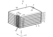
- FIG. 6 is a perspective view of the battery pack 101
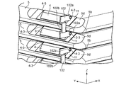
- FIG. 7 is a partially enlarged side view of the vicinity of the positive electrode terminal 3 and the negative electrode terminal 4 of the battery pack 101.
- the battery 100 is laminated so that the first exterior portion 5 thereof faces the second exterior portion 6 of the other battery 100, and the positive electrode terminal 3 and the negative electrode terminal 4 are stacked. Are arranged so that the positive electrode terminal 3 and the negative electrode terminal 4 appear alternately on one end surface of the battery pack 101.
- the positive electrode terminal 3 and the negative electrode terminal 4 of the battery 100 constituting the battery pack 101 are connected by a bus bar 102.
- Both ends of the bus bar 102 are connected to the positive terminal 3 and the negative terminal 4 by welding, and the positive terminal 3 and the negative terminal 4 are electrically connected.
- the positive electrode terminal 3 has, for example, a cylindrical connection portion 3-3 protruding from both side surfaces in the Y-axis direction, and the negative electrode terminal 4 similarly protrudes from both side surfaces in the Y-axis direction, for example, cylindrical connection It has part 4-3.
- the bus bar 102 has a substantially U-shape when viewed from the Y-axis direction, and has, for example, a cylindrical connection portion 3-3 that the positive electrode terminal 3 has at both ends and a cylindrical shape that the negative electrode terminal 4 has, for example.
- a through hole 102a is formed through which the connecting portion 4-3 can be inserted.
- a stress relaxation portion is formed at a portion connecting both ends of the bus bar 102.
- the stress relaxation portion has a substantially U-shaped cross section in the YZ cross section, and even when a force acts in the Z-axis direction, the stress relaxation portion can relieve the force.
- connection part of the positive electrode terminal 3 and the negative electrode terminal 4 is passed through the through hole 102a of the bus bar 102, and the respective connection part and the through hole 102a are fixed by welding, whereby the positive electrode terminal 3 and the negative electrode terminal 4 are fixed. Connect electrically.
- a portion of the bus bar 102 that connects the positive electrode terminal 3 and the negative electrode terminal 4 projects outward from the first exterior portion 5 and the second exterior portion 6 of the battery 100 so that the bus bar 102 does not interfere with the exterior member 5. It has become.
- the above-described stress relieving portion is provided in a portion protruding outward from the first exterior portion 5 and the second exterior portion 6. That is, the contact with the first exterior part 5 and the second exterior part 6 can be avoided by providing the stress relaxation part.
- the bus bar 102 can pass the through hole 102 a through the connection portion of the positive electrode terminal 3 and the negative electrode terminal 4, so when the bus bar 102 is welded to the positive electrode terminal 3 and the negative electrode terminal 4, It becomes easier to fix the bus bar to the welding location, and the welding accuracy can be improved.
- the welding surfaces of the bus bar 102, the positive electrode terminal 3, and the negative electrode terminal 4 are XZ planes, for example, when welding with a laser, the laser irradiation direction is determined in the Y-axis direction. Since the welding direction is constant, the efficiency of the welding operation is improved.
- the positive electrode terminal 3 and the negative electrode terminal 4 are close to one side of the battery 100. For this reason, the welding surfaces of the bus bar 102, the positive electrode terminal 3, and the negative electrode terminal 4 also approach one side of the battery 100. Since the distance between the welding target location and the laser irradiation source is closer to one side than the case where the positive electrode terminal 3 and the negative electrode terminal 4 are in the center of the battery, the laser irradiation distance is reduced. It can be shortened and processing becomes easy. Further, when the XZ plane is the lower surface, the bus bar 102 can be welded in a state of being placed on the positive electrode terminal 3 and the negative electrode terminal 4, so that processing becomes easy.
- the battery 103 shown in FIG. 8 is a nonaqueous electrolyte battery, similar to the battery 100 described in the first embodiment. Similarly to the battery 100, the battery 103 includes an exterior member 40, an electrode group (not shown), a positive electrode terminal 3, a negative electrode terminal 4, and a nonaqueous electrolyte (not shown).
- the exterior member 40 includes a first exterior part 50 and a second exterior part 60.
- the 1st exterior part 50 is a square tube container with a bottom, and has the flange part 50b in the opening part 50a.
- the 1st exterior part 50 consists of stainless steel substantially, for example, or consists of nickel plating steel substantially. When the 1st exterior part 50 is made from stainless steel, the 1st exterior part 50 is produced by shallow drawing, for example from a stainless steel plate.
- the first exterior part 50 has a surface having a maximum area, a long side wall and a short side wall connected to the surface, and a short side wall and a bottom part of the first exterior part 50 are connected to each other.
- a concave portion protruding inward is provided near the center of the corner to be connected, and the bottom of the concave portion is an inclined surface 50d.
- the first exterior portion 50 has a depth shorter than the long side length when the opening 50a is substantially rectangular.
- the more preferable first exterior portion 50 has a depth shorter than the short side length when the opening 50a is substantially rectangular.
- this recessed part is provided in the edge part of the short side wall of the 1st exterior part 50, and the recessed part provided with the positive electrode terminal 3 and the recessed part provided with the negative electrode terminal 4 are provided in the edge part of the same side.
- the bus bar 102 and the positive electrode terminal 3 or the negative electrode terminal 4 of the battery are irradiated with a laser or the like. Then, when welding, it is only necessary to irradiate a laser from one end side, so that the welding operation becomes efficient. Moreover, since the positive electrode terminal 3 and the negative electrode terminal 4 which are the laser irradiation object are formed in the edge part of the battery 103, irradiation distance can be shortened and processing becomes easy.
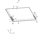
- FIG. 9 is a perspective view of the battery pack 104.
- the battery 103 is stuck so that the second exterior portion thereof faces the fixing plate 70.
- the battery 103 is similarly attached to the back surface of the fixed plate 70 so that the second exterior portion and the fixed plate 70 face each other.
- the battery 103 is fixed to the fixing plate 70 so that the positive electrode terminal 3 and the negative electrode terminal 4 of the battery 103 attached to the fixing plate 70 are on the same side.
- the fixing plate 70 may be made of metal or resin, and may have a water cooling function inside the fixing plate. In the case of a metal, an insulating film may be attached or an insulating coating may be applied. Further, the insulating plate 71 may be sandwiched between the second exterior portion of the battery 103 and the fixing plate 70. The insulating plate 71 is larger than the area of the second exterior portion of the battery 103 and smaller than the maximum area of the fixed plate 70.
- FIG. 10 is a perspective view of a combination of two battery packs 104 shown in FIG. As shown in FIG. 10, the battery 103 is attached to the front and back of the fixed plate 70, and the fixed plates 70 are connected so that the batteries 103 are arranged side by side.
- the positive electrode terminal 3 and the negative electrode terminal 4 of the batteries 103 that are lined up are connected by a bus bar 102.
- the positive terminal 3 and the negative terminal 4 of the battery 103 fixed on the front and back of the fixing plate 70 are also connected by the bus bar 102.
- connection method of the bus bar 102 is the same as that described in the first embodiment, detailed description thereof is omitted.
- the positive electrode terminal 3 and the negative electrode terminal 4 of the battery 103 are provided at the end on the same side, when a plurality of batteries 103 are combined as shown in FIG.
- the distance between the negative electrode terminals 4 is shortened, and the positive electrode terminal 3 and the negative electrode terminal 4 can be connected by a short bus bar such as the bus bar 102. Therefore, the configuration of the bus bar can be made compact, and the energy loss at the bus bar can be minimized.
- the welding surface is an XZ plane, and when laser welding is performed, the laser irradiation direction is all in the Y-axis direction. Since the welding direction is constant, the efficiency of the welding operation is improved.
- FIG. 11 shows a combination of four battery packs shown in FIG.
- the pack exterior 105 can be divided into upper and lower parts, and the upper exterior is omitted in FIG.
- control board 106 for monitoring and controlling the state of the battery is provided on the upper part of these battery packs.
- the wiring connecting the control board 106 and each battery is omitted.
- the battery attached to the fixing plate 70 can be accommodated in the pack exterior 105 as a lump, the assemblability of the battery pack is improved. Furthermore, since the positive electrode terminal 3 and the negative electrode terminal 4 of the battery 103 are all on the control board 106 side, the wiring connecting the positive electrode terminal 3 and the negative electrode terminal 4 and the control board 106 may be shortened in order to measure current and voltage. As a result, assemblability improves. Moreover, heat generation is suppressed by shortening the current path, and charging / discharging at a higher rate is possible.
- a pipe through which a refrigerant flows is embedded in the bottom surface 105a of the pack exterior 105 so that the refrigerant can flow there. If the fixing plate 70 is metallic, the heat is also generated when the battery 103 generates heat. The battery 103 can be cooled by flowing from 70 to the bottom surface 105 a of the pack exterior 105.
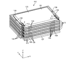
- FIG. 12 shows a battery pack in which a plurality of batteries 103 are stacked.
- the two batteries 103 are bonded together via the insulating plate 72.
- the positive electrode terminal 3 and the negative electrode terminal 4 are bonded together so as to be located on the same side.
- the insulating plate 72 is larger than the area of the second exterior portion 60, and a plurality of through holes 109 are formed in a portion protruding from the second exterior portion 60.
- the through-hole 109 can pass through the fixing rod 108 extending in the Z-axis direction from the peripheral edge of the base 107 provided on the lower side of the plurality of batteries 103 in the Z-axis direction.
- a plurality of laminated batteries 103 are stacked in the Z-axis direction.
- the positive electrode terminal 3 and the negative electrode terminal 4 of the battery 103 are connected to each other by the bus bar 102.
- the battery pack formed by laminating in this way is easy to assemble because it can be formed into a battery pack simply by laminating the two batteries 103 bonded together.
- the plurality of batteries 103 are fixed by the plurality of fixing bars 108, stability can be ensured.
- the irradiation distance is shortened because the positive electrode terminal 3 and the negative electrode terminal 4 to be irradiated with the laser are formed at one end. Can be processed easily. Moreover, since the laser irradiation direction is also constant, the efficiency of the welding operation can be improved.
- the positive electrode, negative electrode, separator, and nonaqueous electrolyte of the batteries according to the first and second embodiments will be described below.
- the positive electrode can include, for example, a positive electrode current collector, a positive electrode material layer held on the positive electrode current collector, and a positive electrode current collector tab.
- the positive electrode material layer can include, for example, a positive electrode active material, a conductive agent, and a binder.
- an oxide or a sulfide can be used as the positive electrode active material.
- oxides and sulfides include manganese dioxide (MnO 2 ) that occludes lithium, iron oxide, copper oxide, nickel oxide, lithium manganese composite oxide (eg, Li x Mn 2 O 4 or Li x MnO 2 ), Lithium nickel composite oxide (eg Li x NiO 2 ), lithium cobalt composite oxide (eg Li x CoO 2 ), lithium nickel cobalt composite oxide (eg LiNi 1-y Co y O 2 ), lithium manganese cobalt composite oxide (For example, Li x Mn y Co 1-y O 2 ), lithium manganese nickel composite oxide having a spinel structure (for example, Li x Mn 2-y Ni y O 4 ), lithium phosphorous oxide having an olivine structure (for example, Li x FePO 4, Li x Fe 1- y Mn y PO 4, Li x CoPO 4), Iron (Fe 2 (SO 4) 3
- V 2 O 5 V 2 O 5
- active material examples include lithium-nickel-cobalt-manganese composite oxide.
- these compounds may be used alone, or a plurality of compounds may be used in combination.
- the binder is blended to bind the active material and the current collector.
- the binder include polytetrafluoroethylene (PTFE), polyvinylidene fluoride (PVdF), and fluorine-based rubber.
- the conductive agent is blended as necessary in order to enhance the current collecting performance and suppress the contact resistance between the active material and the current collector.
- Examples of the conductive agent include carbonaceous materials such as acetylene black, carbon black, and graphite.
- the positive electrode active material and the binder are preferably blended at a ratio of 80% by mass to 98% by mass and 2% by mass to 20% by mass, respectively.
- a sufficient electrode strength can be obtained by setting the binder to an amount of 2% by mass or more. Moreover, the content of the insulating material of an electrode can be reduced by setting it as 20 mass% or less, and internal resistance can be reduced.
- the positive electrode active material, the binder, and the conductive agent are 77% by mass or more and 95% by mass or less, 2% by mass or more and 20% by mass or less, and 3% by mass or more and 15% by mass or less, respectively. It is preferable to mix
- the conductive agent can exhibit the above-described effects by adjusting the amount to 3% by mass or more. Moreover, by setting it as 15 mass% or less, decomposition
- the positive electrode current collector is preferably an aluminum foil or an aluminum alloy foil containing at least one element selected from Mg, Ti, Zn, Ni, Cr, Mn, Fe, Cu and Si.
- the positive electrode current collector is preferably integral with the positive electrode current collecting tab.
- the positive electrode current collector may be a separate body from the positive electrode current collector tab.
- Negative electrode A negative electrode can contain the negative electrode collector, the negative electrode material layer hold
- the negative electrode material layer can include, for example, a negative electrode active material, a conductive agent, and a binder.
- the negative electrode active material for example, a metal oxide, metal nitride, alloy, carbon, or the like that can occlude and release lithium ions can be used. It is preferable to use, as the negative electrode active material, a material capable of inserting and extracting lithium ions at a potential of 0.4 V or higher (vs. Li / Li +).
- the conductive agent is blended in order to enhance the current collecting performance and suppress the contact resistance between the negative electrode active material and the current collector.
- Examples of the conductive agent include carbonaceous materials such as acetylene black, carbon black, and graphite.
- the binder is blended to fill a gap between the dispersed negative electrode active materials and to bind the negative electrode active material and the current collector.
- the binder include polytetrafluoroethylene (PTFE), polyvinylidene fluoride (PVdF), fluorine-based rubber, and styrene butadiene rubber.
- the active material, the conductive agent, and the binder in the negative electrode material layer are blended at a ratio of 68% by mass to 96% by mass, 2% by mass to 30% by mass, and 2% by mass to 30% by mass, respectively. It is preferable.
- the amount of the conductive agent By setting the amount of the conductive agent to 2% by mass or more, the current collecting performance of the negative electrode layer can be improved. Further, by setting the amount of the binder to 2% by mass or more, the binding property between the negative electrode material layer and the current collector can be sufficiently exhibited, and excellent cycle characteristics can be expected.
- the conductive agent and the binder are each preferably 28% by mass or less in order to increase the capacity.
- the current collector a material that is electrochemically stable at the lithium insertion / release potential of the negative electrode active material is used.
- the current collector is preferably made of copper, nickel, stainless steel or aluminum or an aluminum alloy containing at least one element selected from Mg, Ti, Zn, Mn, Fe, Cu and Si.
- the thickness of the current collector is preferably in the range of 5 to 20 ⁇ m. A current collector having such a thickness can balance the strength and weight reduction of the negative electrode.
- the negative electrode current collector is preferably integral with the negative electrode current collecting tab.
- the negative electrode current collector may be a separate body from the negative electrode current collection tab.
- the negative electrode is prepared by suspending a negative electrode active material, a binder and a conductive agent in a commonly used solvent to prepare a slurry, and applying this slurry to a current collector and drying to form a negative electrode material layer It is produced by applying a press.
- the negative electrode may also be produced by forming a negative electrode active material, a binder, and a conductive agent in the form of a pellet to form a negative electrode material layer, which is disposed on a current collector.
- the separator may be formed of, for example, a porous film containing polyethylene, polypropylene, cellulose, or polyvinylidene fluoride (PVdF), or a synthetic resin nonwoven fabric.
- a porous film formed from polyethylene or a polypropylene can melt
- security can be improved.
- At least one organic material selected from the group consisting of polyamideimide, polyamide, polyolefin, polyether, polyimide, polyketone, polysulfone, cellulose, polyvinyl alcohol (PVA), and polyvinylidene fluoride (PVdF) is formed into a string to form an electrode. You may make it adhere and function as a separator.
- Electrolytic Solution for example, a nonaqueous electrolyte can be used.
- the non-aqueous electrolyte may be, for example, a liquid non-aqueous electrolyte prepared by dissolving an electrolyte in an organic solvent, or a gel non-aqueous electrolyte in which a liquid electrolyte and a polymer material are combined.
- the liquid non-aqueous electrolyte is preferably obtained by dissolving the electrolyte in an organic solvent at a concentration of 0.5 mol / L or more and 2.5 mol / L or less.
- Examples of the electrolyte dissolved in the organic solvent include lithium perchlorate (LiClO 4 ), lithium hexafluorophosphate (LiPF 6 ), lithium tetrafluoroborate (LiBF 4 ), and lithium arsenic hexafluoride (LiAsF 6). ), Lithium trifluoromethanesulfonate (LiCF 3 SO 3 ), and lithium salts such as lithium bistrifluoromethylsulfonylimide [LiN (CF 3 SO 2 ) 2 ], and mixtures thereof.
- the electrolyte is preferably one that is difficult to oxidize even at a high potential, and LiPF 6 is most preferred.
- organic solvents examples include cyclic carbonates such as propylene carbonate (PC), ethylene carbonate (EC), and vinylene carbonate; such as diethyl carbonate (DEC), dimethyl carbonate (DMC), and methyl ethyl carbonate (MEC).
- Chain carbonates cyclic ethers such as tetrahydrofuran (THF), 2 methyltetrahydrofuran (2MeTHF), and dioxolane (DOX); chain ethers such as dimethoxyethane (DME) and diethoxyethane (DEE); ⁇ -butyrolactone (GBL), acetonitrile (AN), and sulfolane (SL) are included.
- These organic solvents can be used alone or as a mixed solvent.
- polymer material examples include polyvinylidene fluoride (PVdF), polyacrylonitrile (PAN), and polyethylene oxide (PEO).
- PVdF polyvinylidene fluoride
- PAN polyacrylonitrile
- PEO polyethylene oxide
- a room temperature molten salt (ionic melt) containing lithium ions a polymer solid electrolyte, an inorganic solid electrolyte, or the like may be used as the non-aqueous electrolyte.
- Room temperature molten salt refers to a compound that can exist as a liquid at room temperature (15 to 25 ° C.) among organic salts composed of a combination of an organic cation and an anion.
- the room temperature molten salt includes a room temperature molten salt that exists alone as a liquid, a room temperature molten salt that becomes liquid when mixed with an electrolyte, and a room temperature molten salt that becomes liquid when dissolved in an organic solvent.
- the melting point of a room temperature molten salt used for a nonaqueous electrolyte battery is 25 ° C. or less.
- the organic cation generally has a quaternary ammonium skeleton.
- Exterior member 50 First exterior part 50a ... Opening part 50b ... Flange part 50d ... Inclined surface 60 ... Second exterior part 70 ... Fixing plate 100 ... Battery 101 ... Battery pack 102 ... Bus bar 102a ... Through hole 103 ... Battery 104 ... Battery pack 105 ... Pack exterior 105a ... Bottom surface 106 ... Control board 107 ... Base 108 ... Fixing rod 109 ... Through hole
Abstract
新規な電池及び電池パックの形状については、改善の余地が残されている。 第一端面に対向する第1の辺と第二端面に対応する第2の辺にそれぞれ設けられ傾斜面を有する2つの凹部を含む第1の外装部と、矩形状である第2の外装部とを含み、第1の外装部のフランジ部と第2の外装部が溶接されて形成された空間内に電極群が収納された外装部材と、第1の辺の凹部に設けられた正極端子と、第2の辺の凹部に設けられた負極端子と、を有し、第1の辺及び第2の辺の端部に凹部が設けられる。
Description
本発明の実施形態は、電池及び電池パックに関する。
一次電池及び二次電池などの電池は、一般に、正極及び負極を備えた電極群と、この電極群を収納する外装部材とを具備する。また、様々な用途に適応するため、薄型化柔軟性の向上が可能で、かつ信頼性に優れる外装部材を備えた電池とそれを組み合わせた電池パックが開発されている。
このような新規な電池及び電池パックの形状については、改善の余地が残されている。
上記の課題を解決するために、本実施形態の電池は、正極、前記正極と電気的に接続された正極集電タブ、負極、及び、前記負極と電気的に接続された負極集電タブを含み、前記正極と前記負極がセパレータを介して扁平形状に巻回し、捲回軸の一端面に正極集電タブが位置し、他端に負極集電タブが位置する扁平形状の電極群と、開口部にフランジ部を有する矩形箱状であり、前記第一端面に対向する第1の辺と前記第二端面に対応する第2の辺にそれぞれ設けられ傾斜面を有する2つの凹部を含む第1の外装部と、矩形状である第2の外装部とを含み、前記第1の外装部の前記フランジ部と前記第2の外装部が溶接されて形成された空間内に前記電極群が収納された外装部材と、前記第1の辺の前記凹部に設けられた正極端子と、前記第2の辺の前記凹部に設けられた負極端子と、を有し、前記第1の辺及び前記第2の辺の端部に前記凹部が設けられる。
以下に、実施形態について図面を参照しながら説明する。なお、実施形態を通して共通の構成には同一の符号を付すものとし、重複する説明は省略する。また、各図は実施の形態の説明とその理解を促すための模式図であり、その形状や寸法、比などは実際の装置と異なる個所があるが、これらは以下の説明と公知の技術とを参酌して、適宜設計変更することができる。なお、以下の各図では便宜上、方向が規定されている。X方向は、電池100の長手方向に沿い、Y方向は電池100の短手方向に沿い、Z方向は電池100の厚み方向に沿っている。X方向、Y方向、およびZ方向は、互いに直交している。
(第一の実施形態)
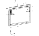
図1に示す電池100は、非水電解質電池である。電池100は、外装部材1と、電極群(図示しない)と、正極端子3と、負極端子4と、非水電解質(図示しない)とを含む。
図1に示す電池100は、非水電解質電池である。電池100は、外装部材1と、電極群(図示しない)と、正極端子3と、負極端子4と、非水電解質(図示しない)とを含む。
図2は電池100の分解斜視図である。図2においては、電極群2を簡略化しているが、図3により詳細な電極群2の斜視図を示す。図1及び図2に示すように、外装部材1は、第1の外装部5と、第2の外装部6とを含む。第1の外装部5は、底付き角筒容器であり、開口部5aにフランジ部5bを有する。第1の外装部5は、例えば、実質的にステンレス鋼からなるか、又は、実質的にニッケルメッキ鋼からなる。第1の外装部5がステンレス鋼製である場合、第1の外装部5は、例えばステンレス鋼板から浅絞り加工によって作製される。図1及び図2に示すように、第1の外装部5は、最大面積を有する面と、それに接続する長辺側壁と短辺側壁を有し、第1の外装部5の短辺側壁と底部とを繋ぐコーナの中央付近に内側に張り出した凹部が設けられており、凹部の底部が傾斜面5dになっている。第1の外装部5は、開口部5aを略長方形とした時の長辺長さよりも短い深さを有するものである。より好ましい第1の外装部5は、開口部5aを略長方形とした時の短辺長さよりも短い深さを有するものである。
また、この凹部は第1の外装部5の短辺側壁の端部に設けられ、後に説明する正極端子3を備える凹部と同じく後に説明する負極端子4を備える凹部とは、第1の外装部5の最大面積を有する面を基準として、対角線上に設けられている。
一方、第2の外装部6は、実質的にステンレス鋼製、又は、実質的にニッケルメッキ鋼からなる矩形板である。第1の外装部5のフランジ部5bが第2の外装部6の四辺に溶接されて形成された空間内に電極群2が収納される。溶接には、例えば、抵抗シーム溶接が用いられる。抵抗シーム溶接は、レーザー溶接に比して低いコストで高い気密性と耐熱性を実現することができる。
電極群2は、図4に示すように、扁平形状で、正極7と、負極8と、正極7と負極8の間に配置されたセパレータ9とを含む。正極7は、例えば箔からなる帯状の正極集電体を有し、この正極集電体は、正極集電体の長辺に平行な一端部からなる正極集電タブ7aと、少なくとも正極集電タブ7aの部分を除いて正極集電体に形成された正極材料層(正極活物質含有層)7bとを含む。一方、負極8は、例えば箔からなる帯状の負極集電体を有し、この負極集電体は、負極集電体の長辺に平行な一端部からなる負極集電タブ8aと、少なくとも負極集電タブ8aの部分を除いて負極集電体に形成された負極材料層(負極活物質含有層)8bとを含む。電極群2は、正極7の正極材料層7bと負極8の負極材料層8bがセパレータ9を介して対向すると共に、捲回軸の一方側に正極集電タブ7aが負極8及びセパレータ9よりも突出し、かつ他方側に負極集電タブ8aが正極7及びセパレータ9よりも突出するように、正極7、セパレータ9及び負極8が扁平形状に捲回されたものである。よって、電極群2において、捲回軸と垂直な第一端面に、扁平の渦巻き状に捲回された正極集電タブ7aが位置する。また、捲回軸と垂直な第二端面に、扁平の渦巻き状に捲回された負極集電タブ8aが位置する。絶縁シート10は、電極群2の最外周のうち、正極集電タブ7a及び負極集電タブ8aを除いた部分を被覆している。なお、電極群2は、非水電解質(図示しない)を保持している。
正極リード12は、導電性の板をU字形状に折り曲げたもので、正極集電タブ7aの両端の湾曲部を除いた部分(中央付近)を挟んで正極集電タブ7a同士を密着させている。また、正極リード12と正極集電タブ7aは溶接により一体化されている。溶接は、例えば超音波溶接により行われる。この正極リード12は後に詳しく説明する正極端子3と電気的に接続されるため、正極端子3は正極リード12を介して正極集電タブ7aに接続されることになる。
負極リード14は、導電性の板をU字形状に折り曲げたもので、負極集電タブ8aの両端の湾曲部を除いた部分(中央付近)を挟んで負極集電タブ8a同士を密着させている。また、負極リード14と負極集電タブ8aは溶接により一体化されている。溶接は、例えば超音波溶接により行われる。この負極リード14は後に詳しく説明する負極端子4と電気的に接続されるため、負極端子4は負極リード14を介して負極集電タブ8aに接続されることになる。
次に、正極端子3について説明する。正極端子3は、頭部と、円筒状の軸部(図示せず)とを含む。正極端子3は、例えば、アルミニウム、アルミニウム合金等の導電性材料から形成される。
図5は、第1の外装部5の開口部を裏側から表したものであるが、傾斜面5dには貫通孔15が形成されている。正極端子に設けられた軸部(図示せず)を貫通孔15に挿入された後、かしめ加工によって塑性変形を生じる。その結果、正極端子3が第1の外装部5と一体化される。なお、正極端子3の軸部の端面と貫通孔15との境界部をレーザーなどで溶接し、より強固な接続を施してもよい。負極端子4も、正極端子と同様の構成であるから、説明を省略する。
正極端子3及び負極端子4を夫々貫通孔15に挿入する際に、絶縁カバー11を正極端子3及び負極端子4と第1の外装部5との間に挟みこむことも可能である。
この絶縁カバー11は、正極端子3及び負極端子4が第1の外装部5と対向する面積よりも広く形成されており、正極端子3及び負極端子4が第1の外装部5に対して電気的に接続されないようになっている。
絶縁カバー11は、例えば、テトラフルオロエチレン・パーフルオロアルキルビニルエーテル共重合体(PFA)、ポリプロピレン(PP)、ポリエチレン(PE)、ナイロン、ポリブチレンテレフタラート(PBT)、ポリエチレンテレフタラート(PET)、ポリテトラフロロエチレン(PTFE)、ポリフェニレンサルファイド(PPS)、及びポリエーテルエーテルケトン(PEEK)等の熱可塑性樹脂から形成される。
電極群2は、第1の外装部5内に、第一端面7aが正極端子3と対向し、かつ第二端面8aが負極端子4と対向するように収納される。
第1の外装部5の短辺側壁と底部5cとを繋ぐコーナ部においては、電極群2の第一端面7aとの間、第二端面8aとの間、それぞれに隙間が存在する。第1の外装部5の短辺側壁と底部とを繋ぐコーナ部に内側に張り出した凹部を設け、凹部の底部を傾斜面5dとすることにより、その凹部の体積分だけ電池の体積が減少するので、電池の体積エネルギー密度を高くすることが可能となる。また、傾斜面5dそれぞれに正極端子3、負極端子4を配置することにより、傾斜面を持たない短辺側面に正極端子3及び負極端子4を設ける場合よりも、端子部の設置面積を増やすことができる。そのため、正極端子3の軸部及び負極端子4の軸部の径を太くすることが可能になるため、低抵抗で大きな電流(ハイレート電流)を流すことが可能となる。
第2の外装部6は、第1の外装部5の蓋として機能する。第1の外装部5のフランジ部5bと第2の外装部6の四辺が溶接されることにより、電極群2が外装部材1内に封止される。
以上説明した電池は、開口部にフランジ部を有するステンレス鋼製の第1の外装部とステンレス鋼製の第2の外装部が溶接されて形成された空間内に電極群が収納される外装部材を含む。第1、第2の外装部がステンレス鋼製であるため、第1、第2の外装部の板厚を薄くした際にも高い強度を保つことができる。その結果、外装部材の柔軟性を高めることができるため、減圧封止又は外装部材の外側から荷重を加える等により電極群を拘束しやすくなる。これにより、電極群の極間距離が安定して抵抗を低くすることができると共に、耐振動性と耐衝撃性を有する電池パックの実現が容易になる。さらに、第1、第2の外装部の柔軟性が高いと、第1、第2の外装部の内面から電極群までの距離を縮めることが容易となるため、電池の放熱性を改善し得る。
ステンレス鋼製の第1、第2の外装部は、溶接がし易く、安価な抵抗シーム溶接により封止が可能である。よって、ラミネートフィルム製容器よりも気体シール性の高い外装部材を低コストで実現することができる。また、外装部材の耐熱性を向上することができる。例えば、SUS304の融点が1400℃であるのに対し、Alの融点は650℃である。
よって、実施形態の電池によれば、第1、第2の外装部の板厚を薄くした際にも高い強度と信頼性を得ることができるため、柔軟性と放熱性に優れ、かつ強度と信頼性の高い電池を提供することができる。
第1の外装部を、開口部の最大長以下の深さを有するものにすると、第1の外装部の開口部面積が広くなる。第1の外装部の四辺に第2の外装部が溶接されるが、開口部面積が大きくなると、溶接される一辺の長さが長くなるため、三辺を先に溶接して残りの一辺の隙間から電解液を注液するのが容易となる。また、溶接強度が他よりも低い箇所を設ける等により外装部材を仮封止することができるため、仮封止用の部品(例えばゴム栓)を不要にすることができる。さらに、外装部材が扁平形状になるため、電池の放熱性を向上することができる。
第1の外装部が傾斜面を有する凹部を含み、傾斜面に端子部を配置することにより、第1の外装部内のデッドスペースを削減することができ、また、軸部の径が太い外部端子を使用することが可能になるため、低抵抗で大きな電流(ハイレート電流)を流すことが可能となる。
第1の外装部及び第2の外装部の板厚は、0.02mm以上0.3mm以下の範囲にすることが望ましい。この範囲にすることにより、機械的強度と柔軟性という相反する性質を両立させることができる。板厚のより好ましい範囲は、0.05mm以上0.15mm以下である。
外装部材は、電池内圧が規定値以上に上昇した際に電池内部の圧力を開放することができる安全弁などを更に備えることもできる。
第一の実施形態に係る電池では、正極端子3と負極端子4が、第1の外装部5の最大面積を有する面を基準として、対角線上に設けられている。電池の正極端子3若しくは負極端子4に対してレーザー等を照射して溶接する際、そのレーザー照射対象が電池の端部に形成されているため照射距離を短くすることができる。よって、レーザーの出力を低下することができ、その溶接設備の簡略化も可能となる。
第1の実施形態に係る電池は、一次電池であってもよいし、又は二次電池であってもよい。第1の実施形態に係る電池の一例としては、リチウムイオン二次電池が挙げられる。
次に、電池100を複数用いた電池パック101について説明する。図6は電池パック101の斜視図、図7は電池パック101の正極端子3及び負極端子4付近を一部拡大した側面図である。
図6及び図7に示した通り、電池100はその第1の外装部5と他の電池100の第2の外装部6とが対向するように積層され、また、正極端子3と負極端子4が接続できるように、電池パック101の一端面に正極端子3と負極端子4が交互に現れるように配置されている。
電池パック101を構成する電池100の正極端子3及び負極端子4はバスバー102により接続される。
より詳しく説明する。バスバー102はその両端部が正極端子3及び負極端子4に溶接により接続され、正極端子3及び負極端子4を電気的に接続している。正極端子3はその両側面からY軸方向に飛び出した、例えば円筒状の接続部位3-3を有し、負極端子4も同様にその両側面からY軸方向に飛び出した、例えば円筒状の接続部位4-3を有している。一方、バスバー102はY軸方向から見て略コの字形状を有しており、その両端部には正極端子3が有する例えば円筒状の接続部位3-3及び負極端子4が有する例えば円筒状の接続部位4-3が挿通可能な透孔102aが形成されている。
また、バスバー102の両端部をつなぐ部分には、応力緩和部が形成されている。応力緩和部は、例えば、YZ断面において略コの字状の断面を有しており、Z軸方向に力が働いた場合であっても、この応力緩和部により力を緩和することが出来る。
電池パック101において、正極端子3及び負極端子4の接続部位をバスバー102の透孔102aに通し、それぞれの接続部位と透孔102aとを溶接により固定することで、正極端子3及び負極端子4を電気的に接続する。
バスバー102のうち正極端子3及び負極端子4をつなぐ部位は、電池100の第1の外装部5および第2の外装部6よりも外側に張り出しており、バスバー102が外装部材5に干渉しないようになっている。また、第1の外装部5および第2の外装部6よりも外側に張り出した部分に、上述した応力緩和部を有する。つまり、応力緩和部を備えることで第1の外装部5および第2の外装部6との接触を回避することができる。
このような電池パック101においては、バスバー102がその透孔102aを正極端子3及び負極端子4の接続部位に通すことが出来るので、バスバー102を正極端子3及び負極端子4に溶接する際に、バスバーを溶接個所に固定しやすくなり、溶接の精度を向上することが出来る。
さらに、バスバー102と正極端子3及び負極端子4の溶接面はXZ平面となるため、例えばレーザーにより溶接する際には、そのレーザー照射方向はY軸方向に定まる。その溶接方向が一定であることから、溶接作業の効率が向上する。
また、正極端子3及び負極端子4は電池100の片側に寄っている。そのため、バスバー102と正極端子3及び負極端子4の溶接面も電池100の片側に寄ることになる。溶接対象箇所とレーザー照射元との距離とが、正極端子3及び負極端子4が電池の中央部にあった場合よりも、片側に寄っている場合の方が近くなるため、レーザーの照射距離を短くすることができ、加工が容易になる。また、XZ平面を下面にした場合、バスバー102を正極端子3及び負極端子4の上に載せた状態で溶接することができるため、加工が容易になる。
(第二の実施形態)
続いて第二の実施形態について説明する。本実施形態は基本的に第一の実施形態と同一の構成であるが、一部異なる部分がある。ここでは第一の実施形態と同一の説明は適宜省略する。
続いて第二の実施形態について説明する。本実施形態は基本的に第一の実施形態と同一の構成であるが、一部異なる部分がある。ここでは第一の実施形態と同一の説明は適宜省略する。
図8に示す電池103は、第一の実施形態で説明した電池100と同様に、非水電解質電池である。電池103は、電池100と同様に外装部材40と、電極群(図示しない)と、正極端子3と、負極端子4と、非水電解質(図示しない)とを含む。
図8に示すように、外装部材40は第1の外装部50と、第2の外装部60とを含む。第1の外装部50は、底付き角筒容器であり、開口部50aにフランジ部50bを有する。第1の外装部50は、例えば、実質的にステンレス鋼からなるか、又は、実質的にニッケルメッキ鋼からなる。第1の外装部50がステンレス鋼製である場合、第1の外装部50は、例えばステンレス鋼板から浅絞り加工によって作製される。図8に示すように、第1の外装部50は、最大面積を有する面と、それに接続する長辺側壁と短辺側壁を有し、第1の外装部50の短辺側壁と底部とを繋ぐコーナの中央付近に内側に張り出した凹部が設けられており、凹部の底部が傾斜面50dになっている。第1の外装部50は、開口部50aを略長方形とした時の長辺長さよりも短い深さを有するものである。より好ましい第1の外装部50は、開口部50aを略長方形とした時の短辺長さよりも短い深さを有するものである。
また、この凹部は第1の外装部50の短辺側壁の端部に設けられ、正極端子3を備える凹部と負極端子4を備える凹部とは、同じ側の端部に設けられている。
その他の構成については、第一の実施形態で説明した電池100と同様であるから、説明を省略する。
第二の実施形態に係る電池103では、正極端子3と負極端子4が、同じ側の端部に設けられているため、バスバー102と電池の正極端子3若しくは負極端子4とをレーザー等を照射して溶接する際、一方の端部側からレーザーを照射すればよく、溶接作業が効率化する。また、そのレーザー照射対象である正極端子3及び負極端子4が電池103の端部に形成されているため、照射距離を短くすることができ、加工が容易になる。
次に、電池103を複数用いた電池パック104について説明する。図9は電池パック104の斜視図である。
図9に示した通り、電池103はその第二の外装部が固定板70に対向するように張り付いている。また、図示していないが、固定板70の裏面にも同様に電池103がその第二の外装部と固定板70が対向するように張り付いている。
この際、固定板70に張り付いている電池103の正極端子3と負極端子4が同じ側になるように、電池103を固定板70に固定していることが好ましい。
固定板70は金属製でも樹脂製でもよく、固定板内部に水冷機能を備えていてもよい。金属であった場合は、絶縁フィルムが貼られていたり、絶縁コーティングがされたものでもよい。また、電池103の第二の外装部と固定板70との間に絶縁板71を挟み込んでいてもよい。絶縁板71は電池103の第二の外装部の面積よりも大きく、固定板70の最大面積よりも小さい。
図10は、図9に示した電池パック104を二つ組み合わせたものの斜視図である。図10に示す通り、電池103を固定板70の表裏に貼り付け、電池103が横並びになるように固定板70同士を接続している。
横並びになった電池103の正極端子3及び負極端子4は、バスバー102によって接続されている。また、固定板70の表裏に固定された電池103の正極端子3及び負極端子4も同様にバスバー102によって接続されている。
バスバー102の接続方法は、第一の実施形態で説明したものと同様であるから、詳しい説明は省略する。
このように、電池103の正極端子3と負極端子4が、同じ側の端部に設けられているため、複数の電池103を図10に示すように組み合わせた場合、電池103の正極端子3及び負極端子4同士の距離が短くなり、バスバー102のように短いバスバーによって正極端子3及び負極端子4を接続することが可能となる。そのため、バスバーの構成をコンパクトにでき、バスバーでのエネルギーロスを最小化することが出来る。
また、図10に示す通り、正極端子3及び負極端子4が同じ側の端部に設けられていることから、それらを接続するバスバー102もすべて同じ側に設けられることになる。図10においては、その溶接面はXZ平面であり、レーザー溶接をする場合は、そのレーザーの照射方向はすべてY軸方向である。その溶接方向が一定であることから、溶接作業の効率が向上する。
図11は、図10に示した電池パックを4つ組み合わせ、それをパック外装105に収容したものを示している。パック外装105は上下の二つに分割することができ、図11においては、その上側の外装を省略している。
また、それらの電池パックの上部には、電池の状態を監視、制御する制御基板106が設けられている。図11においては、制御基板106と各電池をつなぐ配線は省略している。
このように、固定板70に貼り付けた電池を塊としてパック外装105に収容することが出来るので、電池パックの組み立て性が向上する。さらに、電池103の正極端子3及び負極端子4はすべて制御基板106側にあるため、電流や電圧を測定するために正極端子3及び負極端子4と制御基板106とを結ぶ配線を短くすることができるため、組立性などが改善する。また、電流経路を短くすることで発熱を抑え、より高レートでの充放電が可能となる。
また、パック外装105の底面105aに冷媒が流れるパイプを埋め込み、そこに冷媒を流すことができる構成とし、固定板70が金属性であれば、電池103が発熱した際も、その熱が固定板70からパック外装105の底面105aに流れることで、電池103を冷却することが可能となる。
さらに、図11に示すように、パック外装105の上下が分かれる分割位置をパック外装105の上方に設けることで、パック外装105が浸水した場合であっても、その水が内部に侵入する可能性を低減することができる。
図12は、複数の電池103を積層した電池パックを示している。ここでは、二つの電池103を絶縁板72を介して張り合わせている。この際、正極端子3及び負極端子4は同じ側に位置するように張り合わせる。
絶縁板72は第2の外装部60の面積よりも大きく、第2の外装部60からはみ出した部分に、透孔109が複数形成されている。
この透孔109は、複数の電池103のZ軸方向下側に備わる、土台107の周縁部からZ軸方向に延伸している固定棒108を通すことができ、絶縁板72を介して二つの電池103を張り合わせたものを複数個、Z軸方向に積層している。ここでは、電池103の正極端子3及び負極端子4同士はバスバー102によって接続されている。
このように積層してなる電池パックは、二つの電池103を張り合わせたものを積層するだけで電池パック化できるため組立性がよい。また、複数の電池103は複数の固定棒108により固定されているので、安定性も担保することができる。
電池の正極端子3若しくは負極端子4に対してレーザー等を照射して溶接する際、そのレーザー照射対象である正極端子3及び負極端子4が一方の端部に形成されているため照射距離を短くすることができ、加工が容易になる。また、レーザー照射方向も一定であるため、溶接作業の効率化を図ることができる。
第一の実施形態及び第二の実施形態に係る電池の正極、負極、セパレータ及び非水電解質について、以下に説明する。
1)正極
正極は、例えば、正極集電体と、正極集電体に保持された正極材料層と、正極集電タブとを含むことができる。正極材料層は、例えば、正極活物質、導電剤、及び結着剤を含むことができる。
正極は、例えば、正極集電体と、正極集電体に保持された正極材料層と、正極集電タブとを含むことができる。正極材料層は、例えば、正極活物質、導電剤、及び結着剤を含むことができる。
正極活物質としては、例えば、酸化物又は硫化物を用いることができる。酸化物及び硫化物の例には、リチウムを吸蔵する二酸化マンガン(MnO2)、酸化鉄、酸化銅、酸化ニッケル、リチウムマンガン複合酸化物(例えばLixMn2O4またはLixMnO2)、リチウムニッケル複合酸化物(例えばLixNiO2)、リチウムコバルト複合酸化物(例えばLixCoO2)、リチウムニッケルコバルト複合酸化物(例えばLiNi1-yCoyO2)、リチウムマンガンコバルト複合酸化物(例えばLixMnyCo1-yO2)、スピネル構造を有するリチウムマンガンニッケル複合酸化物(例えばLixMn2-yNiyO4)、オリビン構造を有するリチウムリン酸化物(例えばLixFePO4、LixFe1-yMnyPO4、LixCoPO4)、硫酸鉄(Fe2(SO4)3)、バナジウム酸化物(例えばV2O5)及び、リチウムニッケルコバルトマンガン複合酸化物が挙げられる。上記の式において、0<x≦1であり、0<y≦1である。活物質として、これらの化合物を単独で用いてもよく、或いは、複数の化合物を組合せて用いてもよい。
結着剤は、活物質と集電体とを結着させるために配合される。結着剤の例としては、ポリテトラフルオロエチレン(PTFE)、ポリフッ化ビニリデン(PVdF)、フッ素系ゴムが挙げられる。
導電剤は、集電性能を高め、且つ、活物質と集電体との接触抵抗を抑えるために必要に応じて配合される。導電剤の例としては、アセチレンブラック、カーボンブラック及び黒鉛のような炭素質物が挙げられる。
正極材料層において、正極活物質及び結着剤は、それぞれ、80質量%以上98質量%以下及び2質量%以上20質量%以下の割合で配合することが好ましい。
結着剤は、2質量%以上の量にすることにより十分な電極強度を得ることができる。また、20質量%以下にすることにより電極の絶縁材の配合量を減少させ、内部抵抗を減少できる。
導電剤を加える場合には、正極活物質、結着剤及び導電剤は、それぞれ、77質量%以上95質量%以下、2質量%以上20質量%以下、及び3質量%以上15質量%以下の割合で配合することが好ましい。導電剤は、3質量%以上の量にすることにより上述した効果を発揮することができる。また、15質量%以下にすることにより、高温保存下での正極導電剤表面での非水電解質の分解を低減することができる。
正極集電体は、アルミニウム箔、又は、Mg、Ti、Zn、Ni、Cr、Mn、Fe、Cu及びSiから選択される少なくとも1種類の元素を含むアルミニウム合金箔であることが好ましい。
正極集電体は、正極集電タブと一体であることが好ましい。或いは、正極集電体は、正極集電タブと別体でもよい。
2)負極
負極は、例えば、負極集電体と、負極集電体に保持された負極材料層と、負極集電タブとを含むことができる。負極材料層は、例えば、負極活物質、導電剤、及び結着剤を含むことができる。
負極は、例えば、負極集電体と、負極集電体に保持された負極材料層と、負極集電タブとを含むことができる。負極材料層は、例えば、負極活物質、導電剤、及び結着剤を含むことができる。
負極活物質としては、例えば、リチウムイオンを吸蔵及び放出することができる、金属酸化物、金属窒化物、合金、炭素等を用いることができる。0.4V以上(対Li/Li+)貴な電位でリチウムイオンの吸蔵及び放出が可能な物質を負極活物質として用いることが好ましい。
導電剤は、集電性能を高め、且つ、負極活物質と集電体との接触抵抗を抑えるために配合される。導電剤の例としては、アセチレンブラック、カーボンブラック及び黒鉛のような炭素質物が挙げられる。
結着剤は、分散された負極活物質の間隙を埋め、また、負極活物質と集電体とを結着させるために配合される。結着剤の例としては、ポリテトラフルオロエチレン(PTFE)、ポリフッ化ビニリデン(PVdF)、フッ素系ゴム、及びスチレンブタジェンゴムが挙げられる。
負極材料層中の活物質、導電剤及び結着剤は、それぞれ、68質量%以上96質量%以下、2質量%以上30質量%以下、及び2質量%以上30質量%以下の割合で配合することが好ましい。導電剤の量を2質量%以上とすることにより、負極層の集電性能を向上させることができる。また、結着剤の量を2質量%以上とすることにより、負極材料層と集電体との結着性を十分に発現することができ、優れたサイクル特性を期待できる。一方、導電剤及び結着剤はそれぞれ28質量%以下にすることが高容量化を図る上で好ましい。
集電体としては、負極活物質のリチウムの吸蔵電位及び放出電位において電気化学的に安定である材料が用いられる。集電体は、銅、ニッケル、ステンレス又はアルミニウム、或いは、Mg、Ti、Zn、Mn、Fe、Cu、及びSiから選択される少なくとも1種類の元素を含むアルミニウム合金から作られることが好ましい。集電体の厚さは5~20μmの範囲内にあることが好ましい。このような厚さを有する集電体は、負極の強度と軽量化とのバランスをとることができる。
負極集電体は、負極集電タブと一体であることが好ましい。或いは、負極集電体は、負極集電タブと別体でもよい。
負極は、例えば負極活物質、結着剤および導電剤を汎用されている溶媒に懸濁してスラリーを調製し、このスラリーを集電体に塗布し、乾燥させて、負極材料層を形成した後、プレスを施すことにより作製される。負極はまた、負極活物質、結着剤及び導電剤をペレット状に形成して負極材料層とし、これを集電体上に配置することにより作製されてもよい。
3)セパレータ
セパレータは、例えば、ポリエチレン、ポリプロピレン、セルロース、またはポリフッ化ビニリデン(PVdF)を含む多孔質フィルム、または、合成樹脂製不織布から形成されてよい。中でも、ポリエチレン又はポリプロピレンから形成された多孔質フィルムは、一定温度において溶融し、電流を遮断することが可能であるため、安全性を向上できる。
セパレータは、例えば、ポリエチレン、ポリプロピレン、セルロース、またはポリフッ化ビニリデン(PVdF)を含む多孔質フィルム、または、合成樹脂製不織布から形成されてよい。中でも、ポリエチレン又はポリプロピレンから形成された多孔質フィルムは、一定温度において溶融し、電流を遮断することが可能であるため、安全性を向上できる。
また、ポリアミドイミド、ポリアミド、ポリオレフィン、ポリエーテル、ポリイミド、ポリケトン、ポリスルホン、セルロース、ポリビニルアルコール(PVA)及びポリフッ化ビニリデン(PVdF)からなる群から選択される少なくとも1つの有機材料を糸状にして電極に付着させてセパレータとして機能させてもよい。
4)電解液
電解液としては、例えば、非水電解質を用いることができる。
電解液としては、例えば、非水電解質を用いることができる。
非水電解質は、例えば、電解質を有機溶媒に溶解することにより調製される液状非水電解質、又は、液状電解質と高分子材料を複合化したゲル状非水電解質であってよい。
液状非水電解質は、電解質を0.5モル/L以上2.5モル/L以下の濃度で有機溶媒に溶解したものであることが好ましい。
有機溶媒に溶解させる電解質の例には、過塩素酸リチウム(LiClO4)、六フッ化リン酸リチウム(LiPF6)、四フッ化ホウ酸リチウム(LiBF4)、六フッ化砒素リチウム(LiAsF6)、トリフルオロメタンスルホン酸リチウム(LiCF3SO3)、及びビストリフルオロメチルスルホニルイミドリチウム[LiN(CF3SO2)2]のようなリチウム塩、及び、これらの混合物が含まれる。電解質は高電位でも酸化し難いものであることが好ましく、LiPF6が最も好ましい。
有機溶媒の例には、プロピレンカーボネート(PC)、エチレンカーボネート(EC)、及びビニレンカーボネートのような環状カーボネート;ジエチルカーボネート(DEC)、ジメチルカーボネート(DMC)、及びメチルエチルカーボネート(MEC)のような鎖状カーボネート;テトラヒドロフラン(THF)、2メチルテトラヒドロフラン(2MeTHF)、及びジオキソラン(DOX)のような環状エーテル;ジメトキシエタン(DME)、及びジエトキシエタン(DEE)のような鎖状エーテル;γ-ブチロラクトン(GBL)、アセトニトリル(AN)、及びスルホラン(SL)が含まれる。これらの有機溶媒は、単独で、又は混合溶媒として用いることができる。
高分子材料の例には、ポリフッ化ビニリデン(PVdF)、ポリアクリロニトリル(PAN)、及びポリエチレンオキサイド(PEO)が含まれる。
或いは、非水電解質として、リチウムイオンを含有した常温溶融塩(イオン性融体)、高分子固体電解質、無機固体電解質等を用いてもよい。
常温溶融塩(イオン性融体)は、有機物カチオンとアニオンとの組合せからなる有機塩のうち、常温(15~25℃)で液体として存在し得る化合物を指す。常温溶融塩には、単体で液体として存在する常温溶融塩、電解質と混合させることで液体となる常温溶融塩、及び有機溶媒に溶解させることで液体となる常温溶融塩が含まれる。一般に、非水電解質電池に用いられる常温溶融塩の融点は、25℃以下である。また、有機物カチオンは、一般に4級アンモニウム骨格を有する。
本発明のいくつかの実施形態を説明したが、これらの実施形態は、例として提示したものであり、発明の範囲を限定することは意図していない。これら実施形態は、その他の様々な形態で実施されることが可能であり、発明の要旨を逸脱しない範囲で、種々の省略、置き換え、変更を行うことができる。これら実施形態やその変形は、発明の範囲や要旨に含まれると同様に、特許請求の範囲に記載された発明とその均等の範囲に含まれるものである。
1…外装部材
2…電極群
3…正極端子
3-3…接続部位
4…負極端子
4-3…接続部位
5…第1の外装部
5a…開口部
5b…フランジ部
5c…底部
5d…傾斜面
6…第2の外装部
7…正極
7a…第一端面
7a…正極集電タブ
7b…正極材料層
8…負極
8a…負極集電タブ
8a…第二端面
8b…負極材料層
9…セパレータ
10…絶縁シート
11…絶縁カバー
12…正極リード
14…負極リード
15…貫通孔
40…外装部材
50…第1の外装部
50a…開口部
50b…フランジ部
50d…傾斜面
60…第2の外装部
70…固定板
100…電池
101…電池パック
102…バスバー
102a…透孔
103…電池
104…電池パック
105…パック外装
105a…底面
106…制御基板
107…土台
108…固定棒
109…透孔
Claims (7)
- 正極、前記正極と電気的に接続された正極集電タブ、負極、及び、前記負極と電気的に接続された負極集電タブを含み、前記正極と前記負極がセパレータを介して扁平形状に巻回し、捲回軸の一端面に正極集電タブが位置し、他端に負極集電タブが位置する扁平形状の電極群と、
開口部にフランジ部を有する矩形箱状であり、前記第一端面に対向する第1の辺と前記第二端面に対応する第2の辺にそれぞれ設けられ傾斜面を有する2つの凹部を含む第1の外装部と、矩形状である第2の外装部とを含み、前記第1の外装部の前記フランジ部と前記第2の外装部が溶接されて形成された空間内に前記電極群が収納された外装部材と、
前記第1の辺の前記凹部に設けられた正極端子と、
前記第2の辺の前記凹部に設けられた負極端子と、を有し、
前記第1の辺及び前記第2の辺の端部に前記凹部が設けられる電池。 - 前記2つの凹部は、前記第1の辺と前記第2の辺の同じ側に設けられた、請求項1に記載の電池。
- 前記2つの凹部は、前記第1の辺と前記第2の辺に対角線上に設けられた、請求項1に記載の電池。
- 前記第1の外装部と前記第2の外装部はステンレス鋼製である、請求項1乃至請求項3のいずれか一項に記載の電池。
- 前記第1の外装部と前記第2の外装部はニッケルメッキ鋼製である、請求項1乃至請求項3のいずれか一項に記載の電池。
- 正極、前記正極と電気的に接続された正極集電タブ、負極、及び、前記負極と電気的に接続された負極集電タブを含み、前記正極と前記負極がセパレータを介して扁平形状に巻回し、捲回軸の一端面に正極集電タブが位置し、他端に負極集電タブが位置する扁平形状の電極群と、開口部にフランジ部を有する矩形箱状であり、前記第一端面に対向する第1の辺と前記第二端面に対応する第2の辺にそれぞれ設けられ傾斜面を有する二つの凹部を含む第1の外装部と、矩形状である第2の外装部とを含み、前記第1の外装部の前記フランジ部と前記第2の外装部が溶接されて形成された空間内に前記電極群が収納された外装部材と、前記第1の辺の前記凹部に設けられた正極端子と、
前記第2の辺の前記凹部に設けられた負極端子と、を有し、前記第1の辺及び前記第二辺の端部に前記凹部が設けられた複数の電池を備え、
前記電池を前記第2の外装部同士が対向するように積層し、前記正極端子と前記負極端子を電気的に接続した、電池パック。 - 正極、前記正極と電気的に接続された正極集電タブ、負極、及び、前記負極と電気的に接続された負極集電タブを含み、前記正極と前記負極がセパレータを介して扁平形状に巻回し、捲回軸の一端面に正極集電タブが位置し、他端に負極集電タブが位置する扁平形状の電極群と、開口部にフランジ部を有する矩形箱状であり、前記第一端面に対向する第1の辺と前記第二端面に対応する第2の辺にそれぞれ設けられ傾斜面を有する二つの凹部を含む第1の外装部と、矩形状である第2の外装部とを含み、前記第1の外装部の前記フランジ部と前記第2の外装部が溶接されて形成された空間内に前記電極群が収納された外装部材と、前記第1の辺の前記凹部に設けられた正極端子と、
前記第2の辺の前記凹部に設けられた負極端子と、を有し、前記第1の辺及び前記第二辺の端部に前記凹部が設けられた複数の電池を備え、
前記電池を前記第2の外装部と垂直な方向に積層し、前記正極端子と前記負極端子を電気的に接続した、電池パック。
Priority Applications (1)
| Application Number | Priority Date | Filing Date | Title |
|---|---|---|---|
| PCT/JP2018/013376 WO2019186932A1 (ja) | 2018-03-29 | 2018-03-29 | 電池及び電池パック |
Applications Claiming Priority (1)
| Application Number | Priority Date | Filing Date | Title |
|---|---|---|---|
| PCT/JP2018/013376 WO2019186932A1 (ja) | 2018-03-29 | 2018-03-29 | 電池及び電池パック |
Publications (1)
| Publication Number | Publication Date |
|---|---|
| WO2019186932A1 true WO2019186932A1 (ja) | 2019-10-03 |
Family
ID=68059599
Family Applications (1)
| Application Number | Title | Priority Date | Filing Date |
|---|---|---|---|
| PCT/JP2018/013376 WO2019186932A1 (ja) | 2018-03-29 | 2018-03-29 | 電池及び電池パック |
Country Status (1)
| Country | Link |
|---|---|
| WO (1) | WO2019186932A1 (ja) |
Cited By (3)
| Publication number | Priority date | Publication date | Assignee | Title |
|---|---|---|---|---|
| WO2023063328A1 (ja) * | 2021-10-13 | 2023-04-20 | 株式会社Gsユアサ | 蓄電素子 |
| EP4181310A1 (en) * | 2021-11-11 | 2023-05-17 | Toyota Jidosha Kabushiki Kaisha | Secondary battery |
| EP4254610A4 (en) * | 2021-10-22 | 2024-03-13 | Contemporary Amperex Technology Co Ltd | BATTERY, ELECTRICAL DEVICE, METHOD FOR PRODUCING A BATTERY CELL AND DEVICE |
Citations (5)
| Publication number | Priority date | Publication date | Assignee | Title |
|---|---|---|---|---|
| JP2001135358A (ja) * | 1999-08-24 | 2001-05-18 | Toyota Central Res & Dev Lab Inc | 密閉二次電池 |
| JP2002533908A (ja) * | 1998-12-24 | 2002-10-08 | エルジー・ケミカル・リミテッド | 陥没面を有する角柱状容器を利用したリチウムイオン電池 |
| JP2009016122A (ja) * | 2007-07-03 | 2009-01-22 | Nec Tokin Corp | 積層型二次電池および組電池 |
| JP2009507339A (ja) * | 2005-09-02 | 2009-02-19 | エルジー・ケム・リミテッド | 電池モジュールの製作に適した電池 |
| WO2016204147A1 (ja) * | 2015-06-15 | 2016-12-22 | 株式会社 東芝 | 電池及び電池パック |
-
2018
- 2018-03-29 WO PCT/JP2018/013376 patent/WO2019186932A1/ja active Application Filing
Patent Citations (5)
| Publication number | Priority date | Publication date | Assignee | Title |
|---|---|---|---|---|
| JP2002533908A (ja) * | 1998-12-24 | 2002-10-08 | エルジー・ケミカル・リミテッド | 陥没面を有する角柱状容器を利用したリチウムイオン電池 |
| JP2001135358A (ja) * | 1999-08-24 | 2001-05-18 | Toyota Central Res & Dev Lab Inc | 密閉二次電池 |
| JP2009507339A (ja) * | 2005-09-02 | 2009-02-19 | エルジー・ケム・リミテッド | 電池モジュールの製作に適した電池 |
| JP2009016122A (ja) * | 2007-07-03 | 2009-01-22 | Nec Tokin Corp | 積層型二次電池および組電池 |
| WO2016204147A1 (ja) * | 2015-06-15 | 2016-12-22 | 株式会社 東芝 | 電池及び電池パック |
Cited By (3)
| Publication number | Priority date | Publication date | Assignee | Title |
|---|---|---|---|---|
| WO2023063328A1 (ja) * | 2021-10-13 | 2023-04-20 | 株式会社Gsユアサ | 蓄電素子 |
| EP4254610A4 (en) * | 2021-10-22 | 2024-03-13 | Contemporary Amperex Technology Co Ltd | BATTERY, ELECTRICAL DEVICE, METHOD FOR PRODUCING A BATTERY CELL AND DEVICE |
| EP4181310A1 (en) * | 2021-11-11 | 2023-05-17 | Toyota Jidosha Kabushiki Kaisha | Secondary battery |
Similar Documents
| Publication | Publication Date | Title |
|---|---|---|
| JP6794502B2 (ja) | 電池及び電池パック | |
| US10559806B2 (en) | Battery and battery module | |
| JP6173730B2 (ja) | 電池 | |
| JP6173729B2 (ja) | 電池の製造方法 | |
| JP6972175B2 (ja) | 電池パック | |
| CN111886715B (zh) | 电池、电池组、蓄电装置、车辆以及飞翔体 | |
| WO2019186932A1 (ja) | 電池及び電池パック | |
| JP7024109B2 (ja) | 電池、電池パック、電池モジュール、蓄電装置、車両及び飛翔体 | |
| JP7011044B2 (ja) | 電池、電池パック、蓄電装置、車両及び飛翔体 | |
| CN113169368B (zh) | 电池、电池包、蓄电装置、车辆以及飞行体 | |
| WO2019186868A1 (ja) | 電池と電池パック | |
| WO2019049377A1 (ja) | 電池及び電池パック | |
| WO2019187024A1 (ja) | 電池及び電池パック |
Legal Events
| Date | Code | Title | Description |
|---|---|---|---|
| 121 | Ep: the epo has been informed by wipo that ep was designated in this application |
Ref document number: 18911854 Country of ref document: EP Kind code of ref document: A1 |
|
| NENP | Non-entry into the national phase |
Ref country code: DE |
|
| 122 | Ep: pct application non-entry in european phase |
Ref document number: 18911854 Country of ref document: EP Kind code of ref document: A1 |
|
| NENP | Non-entry into the national phase |
Ref country code: JP |