WO2019186927A1 - Steel sheet for hot stamping - Google Patents
Steel sheet for hot stamping Download PDFInfo
- Publication number
- WO2019186927A1 WO2019186927A1 PCT/JP2018/013360 JP2018013360W WO2019186927A1 WO 2019186927 A1 WO2019186927 A1 WO 2019186927A1 JP 2018013360 W JP2018013360 W JP 2018013360W WO 2019186927 A1 WO2019186927 A1 WO 2019186927A1
- Authority
- WO
- WIPO (PCT)
- Prior art keywords
- less
- hot stamping
- martensite
- grain boundary
- steel sheet
- Prior art date
Links
Images
Classifications
-
- C—CHEMISTRY; METALLURGY
- C22—METALLURGY; FERROUS OR NON-FERROUS ALLOYS; TREATMENT OF ALLOYS OR NON-FERROUS METALS
- C22C—ALLOYS
- C22C38/00—Ferrous alloys, e.g. steel alloys
- C22C38/04—Ferrous alloys, e.g. steel alloys containing manganese
-
- C—CHEMISTRY; METALLURGY
- C21—METALLURGY OF IRON
- C21D—MODIFYING THE PHYSICAL STRUCTURE OF FERROUS METALS; GENERAL DEVICES FOR HEAT TREATMENT OF FERROUS OR NON-FERROUS METALS OR ALLOYS; MAKING METAL MALLEABLE, e.g. BY DECARBURISATION OR TEMPERING
- C21D1/00—General methods or devices for heat treatment, e.g. annealing, hardening, quenching or tempering
- C21D1/18—Hardening; Quenching with or without subsequent tempering
-
- C—CHEMISTRY; METALLURGY
- C21—METALLURGY OF IRON
- C21D—MODIFYING THE PHYSICAL STRUCTURE OF FERROUS METALS; GENERAL DEVICES FOR HEAT TREATMENT OF FERROUS OR NON-FERROUS METALS OR ALLOYS; MAKING METAL MALLEABLE, e.g. BY DECARBURISATION OR TEMPERING
- C21D9/00—Heat treatment, e.g. annealing, hardening, quenching or tempering, adapted for particular articles; Furnaces therefor
- C21D9/46—Heat treatment, e.g. annealing, hardening, quenching or tempering, adapted for particular articles; Furnaces therefor for sheet metals
-
- C—CHEMISTRY; METALLURGY
- C22—METALLURGY; FERROUS OR NON-FERROUS ALLOYS; TREATMENT OF ALLOYS OR NON-FERROUS METALS
- C22C—ALLOYS
- C22C38/00—Ferrous alloys, e.g. steel alloys
-
- C—CHEMISTRY; METALLURGY
- C22—METALLURGY; FERROUS OR NON-FERROUS ALLOYS; TREATMENT OF ALLOYS OR NON-FERROUS METALS
- C22C—ALLOYS
- C22C38/00—Ferrous alloys, e.g. steel alloys
- C22C38/001—Ferrous alloys, e.g. steel alloys containing N
-
- C—CHEMISTRY; METALLURGY
- C22—METALLURGY; FERROUS OR NON-FERROUS ALLOYS; TREATMENT OF ALLOYS OR NON-FERROUS METALS
- C22C—ALLOYS
- C22C38/00—Ferrous alloys, e.g. steel alloys
- C22C38/02—Ferrous alloys, e.g. steel alloys containing silicon
-
- C—CHEMISTRY; METALLURGY
- C22—METALLURGY; FERROUS OR NON-FERROUS ALLOYS; TREATMENT OF ALLOYS OR NON-FERROUS METALS
- C22C—ALLOYS
- C22C38/00—Ferrous alloys, e.g. steel alloys
- C22C38/06—Ferrous alloys, e.g. steel alloys containing aluminium
-
- C—CHEMISTRY; METALLURGY
- C22—METALLURGY; FERROUS OR NON-FERROUS ALLOYS; TREATMENT OF ALLOYS OR NON-FERROUS METALS
- C22C—ALLOYS
- C22C38/00—Ferrous alloys, e.g. steel alloys
- C22C38/12—Ferrous alloys, e.g. steel alloys containing tungsten, tantalum, molybdenum, vanadium, or niobium
-
- C—CHEMISTRY; METALLURGY
- C22—METALLURGY; FERROUS OR NON-FERROUS ALLOYS; TREATMENT OF ALLOYS OR NON-FERROUS METALS
- C22C—ALLOYS
- C22C38/00—Ferrous alloys, e.g. steel alloys
- C22C38/18—Ferrous alloys, e.g. steel alloys containing chromium
- C22C38/40—Ferrous alloys, e.g. steel alloys containing chromium with nickel
- C22C38/44—Ferrous alloys, e.g. steel alloys containing chromium with nickel with molybdenum or tungsten
-
- C—CHEMISTRY; METALLURGY
- C22—METALLURGY; FERROUS OR NON-FERROUS ALLOYS; TREATMENT OF ALLOYS OR NON-FERROUS METALS
- C22C—ALLOYS
- C22C38/00—Ferrous alloys, e.g. steel alloys
- C22C38/18—Ferrous alloys, e.g. steel alloys containing chromium
- C22C38/40—Ferrous alloys, e.g. steel alloys containing chromium with nickel
- C22C38/48—Ferrous alloys, e.g. steel alloys containing chromium with nickel with niobium or tantalum
-
- C—CHEMISTRY; METALLURGY
- C22—METALLURGY; FERROUS OR NON-FERROUS ALLOYS; TREATMENT OF ALLOYS OR NON-FERROUS METALS
- C22C—ALLOYS
- C22C38/00—Ferrous alloys, e.g. steel alloys
- C22C38/18—Ferrous alloys, e.g. steel alloys containing chromium
- C22C38/40—Ferrous alloys, e.g. steel alloys containing chromium with nickel
- C22C38/50—Ferrous alloys, e.g. steel alloys containing chromium with nickel with titanium or zirconium
-
- C—CHEMISTRY; METALLURGY
- C22—METALLURGY; FERROUS OR NON-FERROUS ALLOYS; TREATMENT OF ALLOYS OR NON-FERROUS METALS
- C22C—ALLOYS
- C22C38/00—Ferrous alloys, e.g. steel alloys
- C22C38/18—Ferrous alloys, e.g. steel alloys containing chromium
- C22C38/40—Ferrous alloys, e.g. steel alloys containing chromium with nickel
- C22C38/54—Ferrous alloys, e.g. steel alloys containing chromium with nickel with boron
-
- C—CHEMISTRY; METALLURGY
- C22—METALLURGY; FERROUS OR NON-FERROUS ALLOYS; TREATMENT OF ALLOYS OR NON-FERROUS METALS
- C22C—ALLOYS
- C22C38/00—Ferrous alloys, e.g. steel alloys
- C22C38/18—Ferrous alloys, e.g. steel alloys containing chromium
- C22C38/40—Ferrous alloys, e.g. steel alloys containing chromium with nickel
- C22C38/58—Ferrous alloys, e.g. steel alloys containing chromium with nickel with more than 1.5% by weight of manganese
-
- C—CHEMISTRY; METALLURGY
- C22—METALLURGY; FERROUS OR NON-FERROUS ALLOYS; TREATMENT OF ALLOYS OR NON-FERROUS METALS
- C22C—ALLOYS
- C22C38/00—Ferrous alloys, e.g. steel alloys
- C22C38/60—Ferrous alloys, e.g. steel alloys containing lead, selenium, tellurium, or antimony, or more than 0.04% by weight of sulfur
-
- C—CHEMISTRY; METALLURGY
- C21—METALLURGY OF IRON
- C21D—MODIFYING THE PHYSICAL STRUCTURE OF FERROUS METALS; GENERAL DEVICES FOR HEAT TREATMENT OF FERROUS OR NON-FERROUS METALS OR ALLOYS; MAKING METAL MALLEABLE, e.g. BY DECARBURISATION OR TEMPERING
- C21D2211/00—Microstructure comprising significant phases
- C21D2211/002—Bainite
-
- C—CHEMISTRY; METALLURGY
- C21—METALLURGY OF IRON
- C21D—MODIFYING THE PHYSICAL STRUCTURE OF FERROUS METALS; GENERAL DEVICES FOR HEAT TREATMENT OF FERROUS OR NON-FERROUS METALS OR ALLOYS; MAKING METAL MALLEABLE, e.g. BY DECARBURISATION OR TEMPERING
- C21D2211/00—Microstructure comprising significant phases
- C21D2211/003—Cementite
-
- C—CHEMISTRY; METALLURGY
- C21—METALLURGY OF IRON
- C21D—MODIFYING THE PHYSICAL STRUCTURE OF FERROUS METALS; GENERAL DEVICES FOR HEAT TREATMENT OF FERROUS OR NON-FERROUS METALS OR ALLOYS; MAKING METAL MALLEABLE, e.g. BY DECARBURISATION OR TEMPERING
- C21D2211/00—Microstructure comprising significant phases
- C21D2211/008—Martensite
Definitions
- the present invention relates to a steel sheet for hot stamping, which is used as a material for a hot stamping molded body excellent in strength and bending deformability, particularly for structural members and reinforcing members of automobiles and structures that require strength.
- Hot stamping in which press forming is performed after heating a steel sheet to a high temperature in the austenite region, is being promoted.
- Hot stamping has been attracting attention as a technology that achieves both molding on automobile members and ensuring strength, because quenching is performed in the mold simultaneously with pressing.
- a molded body formed by hot stamping a high-strength steel sheet is required to have a performance to absorb an impact at the time of collision.
- Patent Document 1 discloses that a steel sheet for hot stamping is annealed, and Mn and Cr are concentrated in the carbide to form a carbide that is difficult to dissolve. A technique for suppressing growth and reducing the size is disclosed.
- Patent Document 2 discloses a technique for refining austenite by heating at a heating rate of 90 ° C./s or less during hot stamping.
- Patent Literature 3 Patent Literature 4, and Patent Literature 5 also disclose a technique for improving toughness by refining austenite.
- Patent Documents 1 to 5 it is difficult to obtain finer austenite, and it is not possible to obtain strength or bending deformability higher than conventional.
- the present invention provides a hot stamped steel sheet that solves the above problems by securing higher strength or bending deformability in a hot stamped molded body of a high strength steel sheet. With the goal.
- the present inventors diligently studied a method for solving the above problems. As a result, it has been found that when the particle size of the prior austenite of the hot stamped molded product is 3 ⁇ m or less, a strength superior to that of the conventional one can be obtained.
- the number density of cementite or epsilon carbide is 1 ⁇ 10 16 pieces / cm 3 or more in the steel sheet before forming, and further, Nb and Mo It has been found that one or two types may be dissolved in the prior austenite grain boundaries to increase the embrittlement strength of the grain boundaries.
- the texture memory of austenite and martensite is controlled by controlling the X-ray random intensity ratio of ⁇ 112 ⁇ ⁇ 111> which is the crystal orientation of lower bainite, martensite or tempered martensite.
- the present invention has been made based on the above findings and has been further studied, and the gist thereof is as follows.
- thermoforming steel plate that is a material of a hot stamping molded body having excellent strength or bending deformability.
- the feature of the present invention is that the number density of cementite or epsilon carbide is 1 ⁇ 10 16 pieces / cm 3 or more, and further, one or two kinds of Nb and Mo are solid-dissolved in the prior austenite grain boundaries to embrittle the grain boundaries. It is to increase the strength. Furthermore, it is to control the X-ray random intensity ratio of ⁇ 112 ⁇ ⁇ 111> which is the crystal orientation of the crystal grains of the lower bainite, martensite or tempered martensite of the steel sheet. As a result of intensive studies, the present inventors have found that the above structure can be obtained by the following method.
- the amount of molten steel cast per unit time is controlled. Thereby, the microsegregation of Mn in the steel slab is suppressed, the precipitation of Mo and Nb is further suppressed, and the solid solution amount of Mo and Nb in the steel is increased.
- both the finely dispersed carbide and the high-density dislocations become austenite reverse transformation sites, thereby refining the prior austenite grains.
- it is desirable that the carbide is easily dissolved. Therefore, it is important not to concentrate an element that inhibits dissolution of carbides such as Mn and Cr into carbides.
- Mn concentration in the carbide is suppressed, finely-dissolved carbides are formed, and the strength of austenite is introduced by introducing high-density dislocations in the steel.
- this is a crystal orientation that is advantageous to relieve stress generated by transformation, but is preferentially produced.
- the ⁇ 112 ⁇ ⁇ 111> X-ray random intensity ratio of the crystal grains can be controlled.
- These steel sheets for hot stamping exhibit different characteristics by controlling the heating rate in the hot stamping process.
- C 0.35% or more, 0.75% or less
- C is an important element for the hot stamping molded body to obtain a tensile strength of 2000 MPa or more. If it is less than 0.35%, martensite is soft and it is difficult to ensure a tensile strength of 2000 MPa or more, so C is 0.35% or more. Preferably it is 0.37% or more. Considering the balance between required strength and early break suppression, the upper limit is made 0.75%.
- Si 0.005% or more, 0.25% or less
- Si is an element that enhances the deformability and contributes to the improvement of the shock absorption capability. If it is less than 0.005%, the deformability is poor and the impact absorbing ability of the hot stamped article is deteriorated, so 0.005% or more is added. Preferably it is 0.01% or more. On the other hand, if it exceeds 0.25%, the amount of solid solution in the carbide increases and the carbide is difficult to dissolve, making it impossible to control the particle size of the prior austenite of the hot stamped article to 3 ⁇ m, so the upper limit is 0.25% And Preferably it is 0.22% or less.
- Mn 0.5% to 3.0%
- Mn is an element that contributes to improvement in strength by solid solution strengthening. If it is less than 0.5%, the solid solution strengthening ability is poor and the martensite becomes soft, and it is difficult for the hot stamped molded product to secure a tensile strength of 2000 MPa or more, so 0.5% or more is added. Preferably it is 0.7% or more. On the other hand, if added over 3.0%, the amount of solid solution in the carbide increases and the carbide is difficult to dissolve, making it impossible to control the particle size of the prior austenite of the hot stamped article to 3 ⁇ m or less. % Is the upper limit. Preferably, it is 2.5% or less.
- Al is an element that acts to deoxidize molten steel and to make the steel sound. If it is less than 0.0002%, deoxidation is sufficient and a coarse oxide having a diameter of 5 ⁇ m or more is generated to cause early breakage. Al is made 0.0002% or more. Preferably it is 0.0010% or more. On the other hand, if added over 3.0%, a coarse oxide is generated and toughness is impaired, so the content is made 3.0% or less. Preferably it is 2.5% or less, More preferably, it is 0.5% or less.
- Cr 0.05% or more, 1.00% or less
- Cr is an element that contributes to improvement in strength by solid solution strengthening. If it is less than 0.05%, the solid solution strengthening ability is poor and the martensite becomes soft, and it is difficult for the hot stamped molded product to ensure a tensile strength of 2000 MPa or more, so 0.05% or more is added. Preferably it is 0.1% or more. On the other hand, if added over 1.00%, the amount of solid solution in the carbide increases and the carbide is difficult to dissolve, making it impossible to control the particle size of the prior austenite of the hot stamped article to 3 ⁇ m or less. % Is the upper limit. Preferably, it is 0.8% or less.
- B 0.0005% or more and 0.010% or less
- B is an element that contributes to improving the strength by solid solution strengthening. If it is less than 0.0005%, the solid solution strengthening ability is poor and the martensite becomes soft, and it is difficult for the hot stamped molded product to secure a tensile strength of 2000 MPa or more, so 0.0005% or more is added. Preferably it is 0.0008% or more. On the other hand, if added over 0.010%, the amount of solid solution in the carbide increases and the carbide is difficult to dissolve, making it impossible to control the particle size of the prior austenite of the hot stamped article to 3 ⁇ m or less. % Is the upper limit. Preferably, it is 0.007% or less.
- Nb 0.01% or more and 0.15% or less
- Nb is an element that dissolves in the grain boundary of prior austenite and increases the strength of the grain boundary.
- Nb improves the embrittlement strength of the grain boundary because it dissolves at the grain boundary and inhibits P grain boundary segregation.
- the strength of austenite can be increased by dissolving Nb and Mo in the austenite immediately after finish rolling and further controlling the coil winding conditions, from austenite to lower bainite, martensite or tempered martensite.
- the crystal orientation is advantageous to relieve the stress generated by the transformation, but it is preferentially generated. As a result, the ⁇ 112 ⁇ ⁇ 111> X-ray random intensity ratio of the crystal grains can be controlled.
- 0.01% or more is added. Preferably it is 0.030% or more.
- it if added over 0.15%, it becomes easy to precipitate as a carbide, and the amount of solid solution at the grain boundary decreases, so it is made 0.15% or less.
- it is 0.12% or less.
- Mo 0.005% or more and 1.00% or less
- Mo is an element that dissolves in the grain boundary of prior austenite and increases the strength of the grain boundary.
- Mo inhibits P grain boundary segregation by forming a solid solution at the grain boundary, the embrittlement strength of the grain boundary is improved.
- the strength of austenite can be increased by dissolving Nb and Mo in the austenite immediately after finish rolling and further controlling the coil winding conditions, from austenite to lower bainite, martensite or tempered martensite.
- the crystal orientation is advantageous to relieve the stress generated by the transformation, but it is preferentially generated. As a result, the ⁇ 112 ⁇ ⁇ 111> X-ray random intensity ratio of the crystal grains can be controlled.
- 0.005% or more is added.
- it is 0.030% or more.
- the content is made 1.00% or less.
- it is 0.80% or less.
- Ti 0% or more, 0.15% or less
- Ti is not an essential element, but Ti is an element that contributes to improvement in strength by solid solution strengthening, and may be added as necessary.
- it is preferable to set it as 0.01% or more.
- it is 0.02%.
- coarse carbides and nitrides having a diameter of 5 ⁇ m or more are formed to cause early fracture, so the content is made 0.15% or less.
- it is 0.12% or less.
- Ni 0% or more and 3.00% or less
- Ni is not an essential element, it is an element that contributes to improvement in strength by solid solution strengthening, and may be added as necessary.
- it is preferable to set it as 0.01% or more.
- it is 0.02%.
- the steel becomes brittle and causes premature fracture, so the content is made 3.00% or less.
- it is 2.00% or less.
- P 0.10% or less
- P is an impurity element and is an element that easily segregates at the grain boundary and lowers the embrittlement strength of the grain boundary. If it exceeds 0.10%, the embrittlement strength of the grain boundary is remarkably lowered and premature fracture is caused, so P is made 0.10% or less. Preferably it is 0.050% or less.
- the lower limit is not particularly limited, but if it is reduced to less than 0.0001%, the de-P cost increases significantly and becomes economically disadvantageous, so 0.0001% is a practical lower limit on a practical steel sheet.
- S is an impurity element and is an element that forms inclusions. If it exceeds 0.10%, inclusions are generated and cause early breakage, so S is made 0.10% or less. Preferably it is 0.0050% or less.
- the lower limit is not particularly limited, but if it is reduced to less than 0.0015%, the de-S cost is significantly increased, which is economically disadvantageous, so 0.0015% is a practical lower limit on a practical steel sheet.
- N 0.010% or less
- N is an impurity element, and forms nitrides and causes early breakage. Therefore, the N content is set to 0.010% or less. Preferably it is 0.0075% or less.
- the lower limit is not particularly limited, but if it is reduced to less than 0.0001%, the de-N cost greatly increases and becomes economically disadvantageous, so 0.0001% is a practical lower limit on a practical steel sheet.
- the balance of the component composition is Fe and impurities.
- impurities include elements that are allowed from steel raw materials or scraps and / or inevitably mixed in the steel making process, and are allowed to the extent that they do not impair the properties of the hot stamped article of the present invention.
- the microstructure of the steel sheet for hot stamping needs to contain martensite or tempered martensite having an area ratio of 90% or more. Preferably it is 94% or more.
- the microstructure may be lower bainite. The remainder is not particularly defined, and examples thereof include upper bainite, retained austenite, and pearlite.
- the area ratio of lower bainite, martensite, and tempered martensite is measured as follows.
- the corroded sample is washed with acetone or ethyl alcohol, dried, and subjected to observation with a scanning electron microscope.
- the scanning electron microscope used is assumed to be equipped with a two-electron detector.
- the sample was irradiated with an electron beam at an acceleration voltage of 10 kV and an irradiation current level of 8, and the sample thickness was 1/8 to 3/8 centered on the 1/4 position.
- a secondary electron image of the range is taken.
- the photographing magnification is 10,000 times on the basis of a screen of 386 mm wide ⁇ 290 mm long, and the number of photographing fields is 10 fields or more.
- the crystal grain boundary and the carbide are captured with a bright contrast, and therefore the structure can be easily determined by the position of the crystal grain boundary and the carbide.
- carbide is formed inside the crystal grain, it is tempered martensite or lower bainite, and the structure where the carbide is not observed inside the crystal grain is martensite.
- the structure in which carbides are formed at the grain boundaries is upper bainite or pearlite.
- the same field of view as the position where the secondary electron image is taken is measured by an electron backscatter diffraction method.
- the scanning electron microscope to be used is equipped with a camera capable of electron backscatter diffraction.
- the sample In a vacuum of 9.6 ⁇ 10 ⁇ 5 or less, the sample is irradiated with an electron beam at an acceleration voltage of 25 kV and an irradiation current level of 16, and a face-centered cubic lattice map is created from the obtained measurement data.
- the imaging magnification is to create a mesh of 2 ⁇ m intervals on a photograph taken at a magnification of 10,000 with reference to a screen of horizontal 386 mm ⁇ longitudinal 290 mm, and select a microstructure located at the intersection of the mesh.
- a value obtained by dividing the number of intersections of each structure by all the intersections is defined as the area fraction of the microstructure. This operation is performed in 10 fields of view, and the average value is calculated as the area ratio of the microstructure.
- the grain boundary solid solution ratio Z defined by equation (1) is 0.4 or more
- the grain boundary solid solution ratio Z defined by the above formula (1) is an important structural factor in securing excellent shock absorbing ability, and is an index adopted by the present inventors for evaluating shock absorbing ability. is there.
- Nb and / or Mo When Nb and / or Mo is dissolved at the grain boundary, P is less likely to segregate at the grain boundary, and the bonding strength of the grain boundary is increased, so that the embrittlement strength of the grain boundary is increased and the shock absorbing ability is improved. If the grain boundary solid solution ratio Z of the hot stamped product is less than 0.4, the grain boundary strengthening effect of Nb and / or Mo cannot be sufficiently obtained, and the required impact absorbing ability cannot be obtained.
- the grain boundary solid solution amount of Nb and Mo is reduced by heat treatment, so the grain boundary solid solution ratio Z is set to 0.4 or more. Preferably it is 0.5 or more.
- the upper limit is not particularly limited, but theoretically 1.0 is the upper limit.
- the grain boundary solid solution ratio Z is measured as follows.
- test piece is immersed in a 20% ammonium thiocyanate solution for 72 to 120 hours.
- the test piece is set in the analyzer and is broken from the cut portion of the test piece in a vacuum of 9.6 ⁇ 10 ⁇ 5 or less to expose the prior austenite grain boundaries.
- the exposed prior austenite grain boundary is irradiated with an electron beam at an acceleration voltage of 1 to 30 kV, and the mass% (concentration) of Nb and / or Mo at the grain boundary is measured.
- the measurement is carried out at 10 or more old austenite grain boundaries. Complete the measurement within 30 minutes after failure to prevent grain boundary contamination.
- the average value of mass% (concentration) of the obtained Nb and / or Mo is calculated, and the value obtained by dividing by the mass% of added Nb and / or Mo is defined as the grain boundary solid solution ratio Z.
- the X-ray random intensity ratio is 2.8 or more.
- the X-ray random intensity ratio is preferably 3.0 or more.
- a mirror surface is finished using a liquid in which a diamond powder having a particle size of 1 to 6 ⁇ m is dispersed in a diluent such as alcohol or pure water.
- finish polishing is performed using a standard colloidal silica suspension (particle size: 0.04 ⁇ m).
- the polished sample is washed with acetone or ethyl alcohol, dried, and set in a scanning electron microscope.
- the scanning electron microscope used is assumed to be equipped with an EBSD detector (TSL DVC5 detector).
- Crystal orientation information is obtained by EBSD measurement at a measurement interval of 0.2 ⁇ m in the range of 500 ⁇ m in the plate thickness direction and 1000 ⁇ m in the rolling direction at the plate thickness 3/8 to 5/8 positions.
- the measurement conditions are a vacuum level of 9.6 ⁇ 10 ⁇ 5 or less, an acceleration voltage of 15 kV, an irradiation current level of 13, a binning size of 8 ⁇ 8, and an exposure time of 62 seconds.
- the measurement data is analyzed using software “OIM Analysis (registered trademark)” attached to the EBSD analyzer, and the X-ray random intensity ratio of ⁇ 112 ⁇ ⁇ 111> is calculated.
- Using the “Texture” function and the “Crystal orientation distribution function” function, which are parameters installed in the software, a crystal orientation distribution function of ⁇ 2 45 ° cross section is drawn.
- the X-ray random intensity ratio at the ⁇ 112 ⁇ ⁇ 111> pole position is read from the drawn image.
- the total number density of cementite and epsilon carbide with a particle size of 50 nm or less is 1 ⁇ 10 16 / cm 3 or more” If the total number density of cementite and epsilon carbide having a particle size of 50 nm or less is 1 ⁇ 10 16 pieces / cm 3 or more, the finely dispersed carbides become the reverse transformation sites of austenite, so that The prior austenite grains can be refined. If the number density is less than 1 ⁇ 10 16 pieces / cm 3 , the effect cannot be obtained, so 1 ⁇ 10 16 pieces / cm 3 is the lower limit. Preferably, it is 3 ⁇ 10 16 pieces / cm 3 .
- the upper limit is not particularly defined, the upper limit is set to 1000 ⁇ 10 16 pieces / cm 3 in view of the balance between required strength and early fracture suppression.
- generated will become a cementite and an epsilon carbide
- a mirror surface is finished using a liquid in which a diamond powder having a particle size of 1 ⁇ m to 6 ⁇ m is dispersed in a diluent such as alcohol or pure water.
- the observation surface of the sample is immersed in an acetylacetone-based electrolytic solution, and electrolysis is performed for 2 seconds at an electrolytic potential of 300 mV.
- the sample after the electric field is washed with acetone or ethyl alcohol, dried, and set in a scanning electron microscope.
- the scanning electron microscope used is a model equipped with a secondary electron detector. In a vacuum of 9.6 ⁇ 10 ⁇ 5 or less, the sample was irradiated with an electron beam at an acceleration voltage of 10 kV and an irradiation current level of 8.
- the sample had a plate thickness of 3/8 to 5/8, and 386 mm wide ⁇ 290 mm long. 10 fields of view having a magnification of 30000 times are observed on the basis of the screen.
- the molten steel which has the above-mentioned chemical composition is made into a steel piece (slab) by a continuous casting method.
- the molten steel casting amount per unit time is set to 6 ton / min or less.
- the casting amount (casting speed) per unit time of molten steel exceeds 6 ton / min during continuous casting, microsegregation of Mn increases and the nucleation amount of precipitates mainly composed of Mo and Nb increases. .
- the casting amount is 5 ton / min or less.
- the lower limit of the casting amount is not particularly limited, but is preferably 0.1 ton / min or more from the viewpoint of operation cost.
- Hot rolling process The above-mentioned steel slab is hot-rolled to obtain a steel plate. At that time, the hot rolling is finished in a temperature range defined by the formula (2) of A3 transformation temperature + 30 ° C. or more and A3 transformation temperature + 200 ° C. or less, and the final rolling reduction at that time is set to 12% or more. Cooling is started within 1 second after the completion, and the temperature range from the finish rolling finish temperature to 550 ° C. is cooled at a cooling rate of 100 ° C./second or more and wound at a temperature of less than 500 ° C.
- A3 transformation temperature 850 + 10 ⁇ (C + N) ⁇ Mn + 350 ⁇ Nb + 250 ⁇ Ti + 40 ⁇ B + 10 ⁇ Cr + 100 ⁇ Mo (2)
- the austenite recrystallization is promoted by setting the finish rolling temperature to A3 transformation temperature + 30 ° C. or higher. Thereby, the formation of a low-angle grain boundary in the crystal grains is suppressed, and the precipitation sites of Nb and Mo can be reduced.
- it is A3 transformation temperature +50 degreeC or more.
- finish rolling temperature By setting the finish rolling temperature to A3 transformation temperature + 200 ° C. or less, excessive grain growth of austenite is suppressed.
- finish rolling in a temperature range of A3 transformation temperature + 200 ° C. or less recrystallization of austenite is promoted, and excessive grain growth does not occur. Therefore, fine carbides can be obtained in the winding process.
- it is A3 transformation temperature +150 degrees C or less.
- Austenite recrystallization is promoted by setting the reduction ratio of finish rolling to 12% or more. Thereby, the formation of a low-angle grain boundary in the crystal grains is suppressed, and the precipitation sites of Nb and Mo can be reduced. Preferably, it is 15% or more.
- Nb and Mo in austenite By starting cooling within 1 second after finishing rolling, preferably within 0.8 seconds, and cooling the temperature range from the finishing rolling finishing temperature to 550 ° C. at a cooling rate of 100 ° C./second or more, Nb and The residence time in the temperature range where the precipitation of Mn is promoted can be reduced. As a result, precipitation of Nb and Mo in austenite can be suppressed, and the amount of Nb and Mo dissolved in the austenite grain boundary increases.
- the coiling temperature By making the coiling temperature less than 500 ° C., the above effect is enhanced, and Mn concentration in the carbide is suppressed, easily dissolving fine carbides are generated, and high density dislocations are introduced into the steel. To do. Preferably it is less than 480 degreeC.
- the coiling temperature exceeds 500 ° C., the number density of cementite and epsilon carbide having a particle diameter of 50 nm or less does not become 1 ⁇ 10 16 pieces / cm 3 or more in total.
- the lower limit is not particularly defined, but it is difficult to wind up at room temperature or lower in actual operation, so the room temperature is the lower limit.
- Nb and Mo are dissolved in austenite.
- an advantageous crystal orientation is preferentially generated, so as described above, cooling is started within 1 second after the finish rolling is finished, and the finish rolling finish temperature is increased to 550 ° C.
- cooling the temperature range at a cooling rate of 100 ° C./second or more the ⁇ 112 ⁇ ⁇ 111> X-ray random intensity ratio of the crystal grains can be controlled.
- a plating layer may be formed on the surface of the steel sheet for the purpose of improving corrosion resistance.
- the plating layer may be either an electroplating layer or a hot dipping layer.
- Examples of the electroplating layer include an electrogalvanizing layer and an electro Zn—Ni alloy plating layer.
- the hot dip galvanized layer includes hot dip galvanized layer, alloyed hot dip galvanized layer, hot dip aluminum plated layer, hot dip Zn-Al alloy plated layer, hot dip Zn-Al-Mg alloy plated layer, hot dip Zn-Al-Mg-Si alloy.
- a plating layer etc. are illustrated.
- the adhesion amount of the plating layer is not particularly limited and may be a general adhesion amount.
- Manufacturing method A Manufacturing method for obtaining a hot stamping molded body having excellent strength Heating and holding a steel sheet for hot stamping at a temperature range of 500 ° C. or higher and A3 or lower at an average heating rate of 100 ° C./s or higher and less than 200 ° C./s Then, hot stamping is performed, and after molding, the molded body is cooled to room temperature. In order to adjust the strength, a part or all of the hot stamping body may be tempered at a temperature of 200 ° C. or higher and 500 ° C. or lower.
- both easily soluble fine carbides and high-density dislocations become nucleation sites of prior austenite.
- the average particle size of the prior austenite can be controlled to 3 ⁇ m or less.
- precipitation of NbC and MoC during heating is suppressed, and this contributes to an increase in the solid solution ratio of one or two of Nb and Mo at the grain boundaries of the prior austenite.
- it is 120 ° C./s or more.
- the upper limit is 200 ° C./s. Preferably, it is less than 180 ° C./s.
- the holding temperature at the time of hot stamping is preferably A3 point + 50 ° C. or higher and A3 point + 150 ° C. or lower.
- the cooling rate after hot stamping is preferably 10 ° C./s or more.
- the holding temperature at the time of hot stamping is preferably A3 point + 10 ° C. or higher and A3 point + 150 ° C. or lower.
- the cooling rate after hot stamping is preferably 10 ° C./s or more.
- the conditions in the examples are one example of conditions used for confirming the feasibility and effects of the present invention, and the present invention is based on this one example of conditions. It is not limited.
- the present invention can adopt various conditions as long as the object of the present invention is achieved without departing from the gist of the present invention.
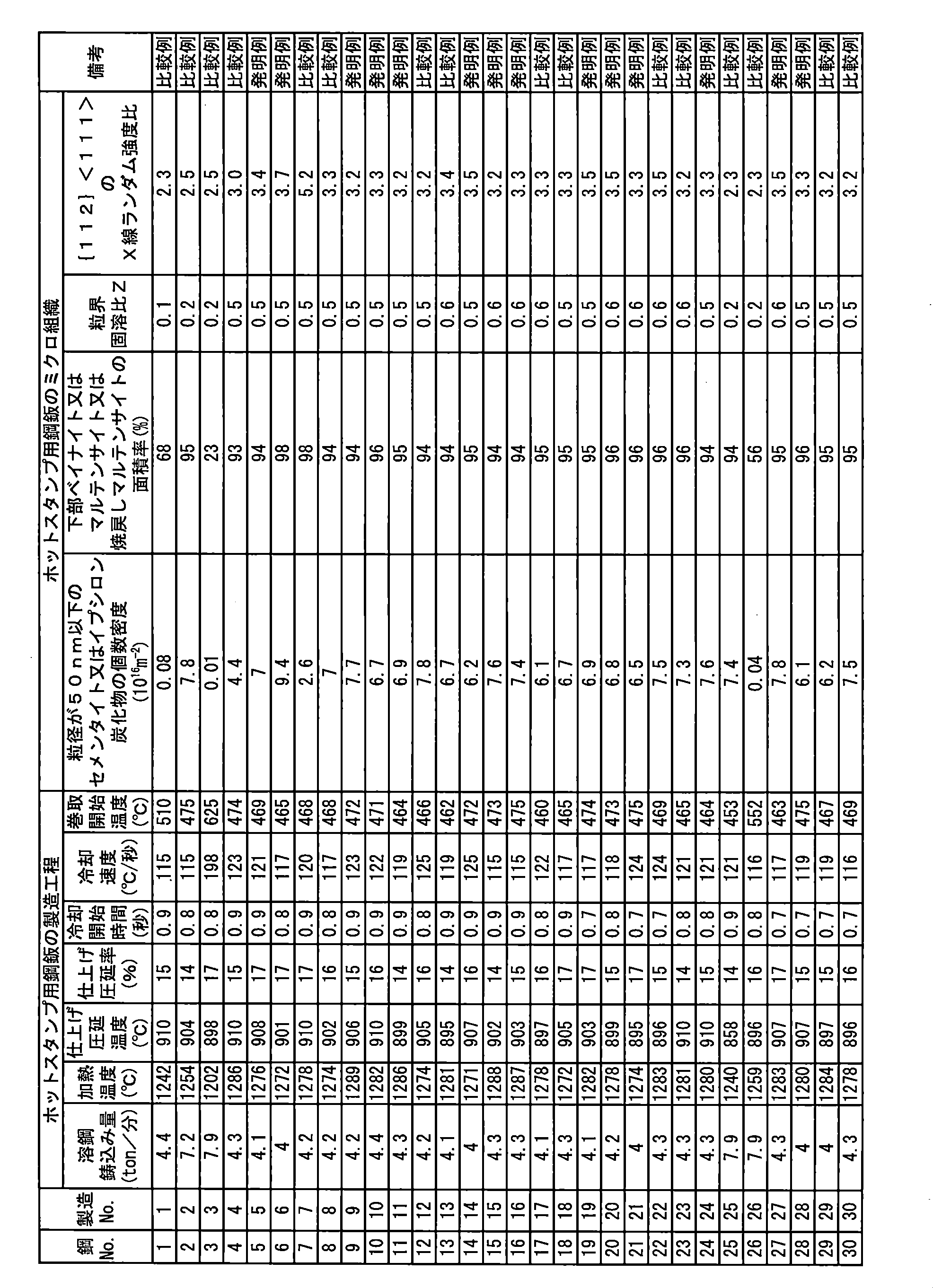
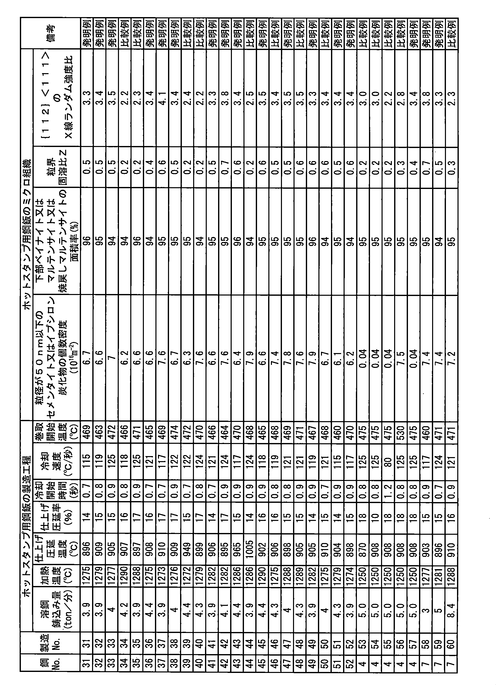
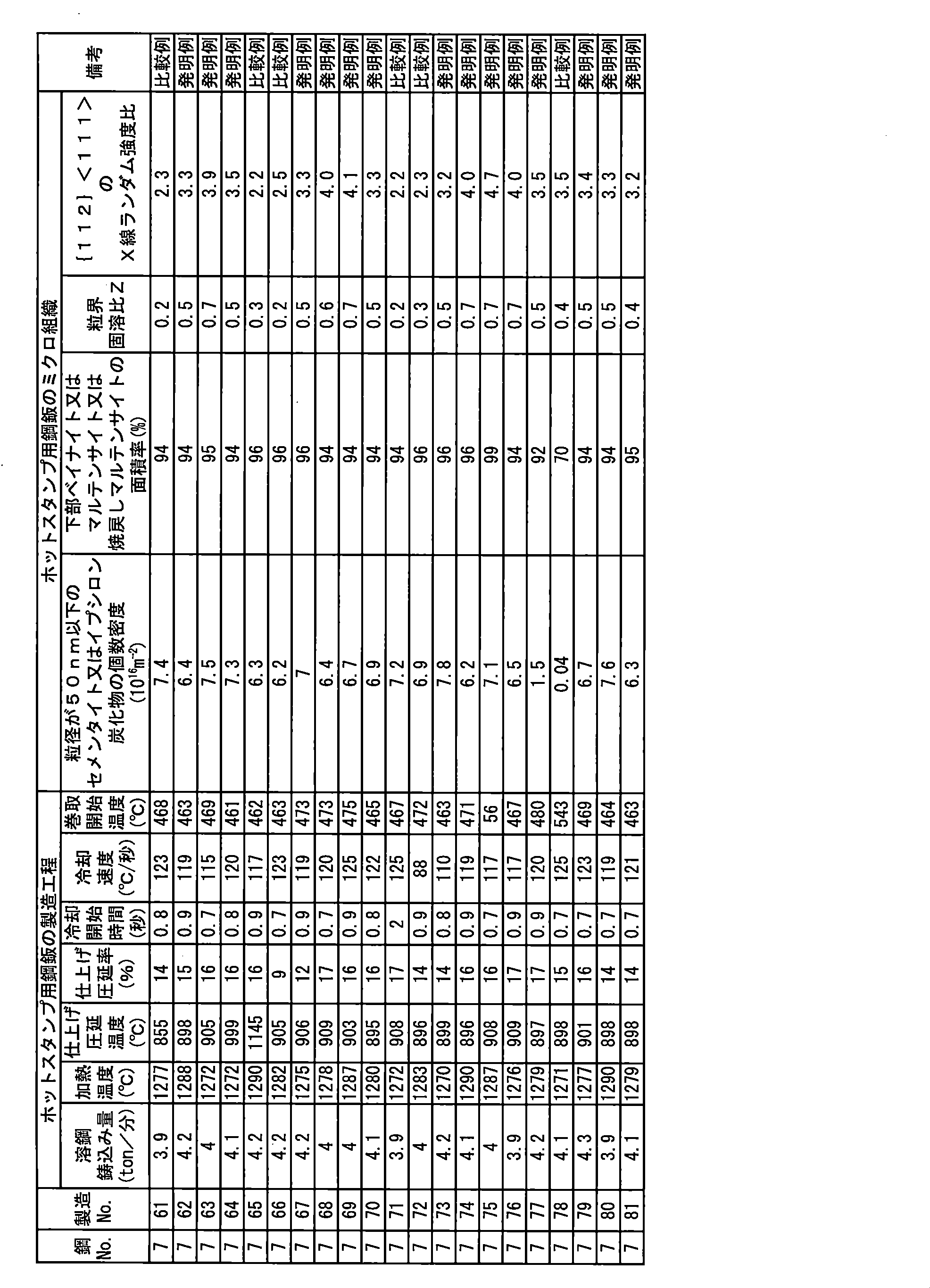
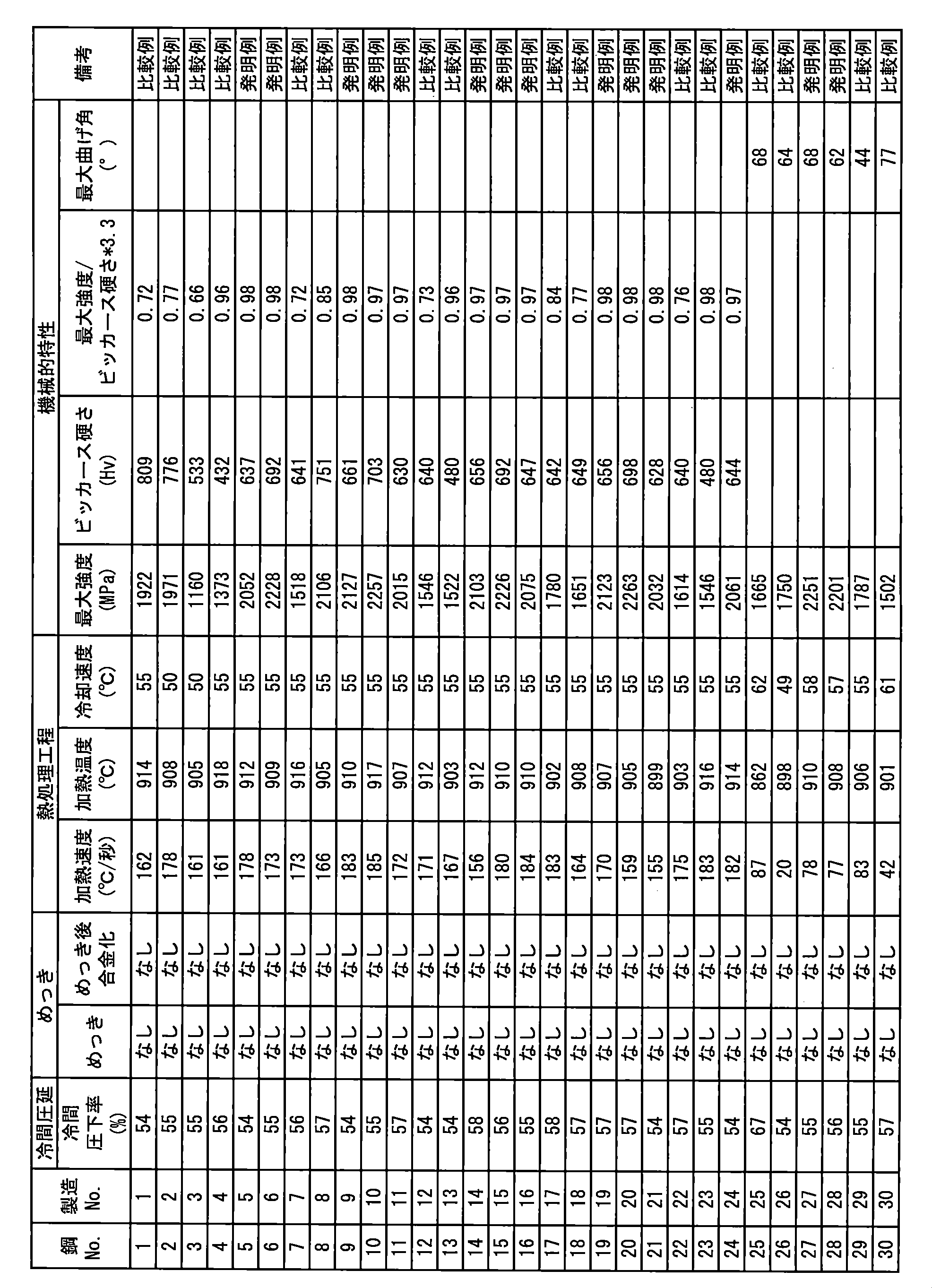
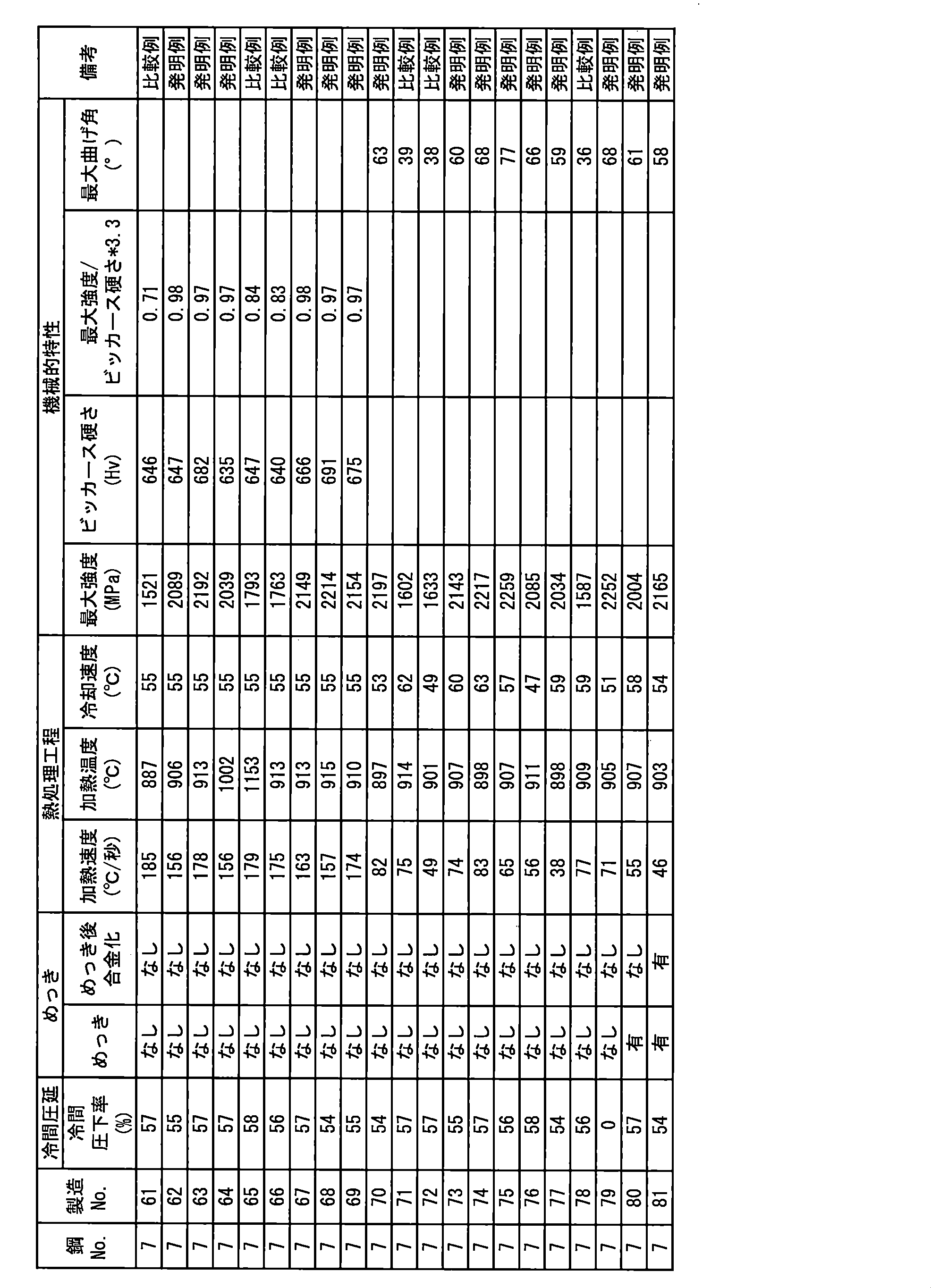
- the steel pieces produced by casting molten steel having the composition shown in Table 1 were hot-rolled as shown in Table 2 to obtain hot stamping steel plates.
- the ⁇ 112 ⁇ ⁇ 111> X-ray random intensity ratio and the number density of cementite and epsilon carbide having a particle size of 50 nm or less were measured.
- hot stamping steel plate cold rolling and plating were performed under the conditions shown in Table 3 to prepare a hot stamping molded body.
- the heat treatment at the time of hot stamping was performed at various speeds in an average heating rate in a temperature range of 500 ° C. or higher and A3 point or lower.
- the samples prepared with the hot stamping molded article at an average heating rate in the temperature range of 500 ° C. or higher and A3 point or lower at 100 ° C./s or higher were measured for tensile strength and further evaluated for impact absorbing ability.
- the samples prepared with the hot stamping molded bodies at an average heating rate in the temperature range of 500 ° C. or more and A3 points or less and less than 100 ° C./s were measured for tensile strength and further evaluated for bending deformability.
- the impact absorbing ability was evaluated by the presence or absence of early breakage, and a material that did not break early according to the following evaluation criteria was accepted.
- Excellent shock absorption means that the amount of energy absorbed at the time of collision is large. That is, the integrated value in the stress-strain curve is large, and this can be evaluated by not breaking early (breaking after reaching the maximum stress).
- the Vickers hardness of the material was measured by the following method.
- a section perpendicular to the plate surface is cut out from the hot stamping body, the measurement surface is polished using # 600 to # 1500 silicon carbide paper, and then diamond powder with a particle size of 1 to 6 ⁇ m is diluted with alcohol or other pure solution. Use a liquid dispersed in water to give a mirror finish. Using a Vickers hardness tester, 10 points were measured at a load of 1 kgf at a thickness of 1/4 position at an interval of 3 times or more of the indentation, and the average value was defined as the hardness of the steel plate.
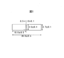
- the bending deformability was evaluated under the following measurement conditions based on the VDA standard (VDA238-100) defined by the German Automobile Manufacturers Association.
- VDA238-100 the displacement at the maximum load obtained by a bending test is converted into an angle based on the VDA, the maximum bending angle is obtained, and a material having a maximum bending angle of 50 ° or more is regarded as acceptable.
- the steel sheet for hot stamping of the present invention has a tensile strength of 2000 MPa or more and was confirmed to have an excellent bending deformability. On the other hand, in the example where the chemical composition and the manufacturing method are not appropriate, the target characteristics were not obtained.
Abstract
Description
Cは、ホットスタンプ成形体が2000MPa以上の引張強さを得るために重要な元素である。0.35%未満では、マルテンサイトが軟らかく、2000MPa以上の引張強さを確保することが困難であるので、Cは0.35%以上とする。好ましくは0.37%以上である。要求される強度と早期破断抑制のバランスを鑑みて、上限は0.75%とする。 "C: 0.35% or more, 0.75% or less"
C is an important element for the hot stamping molded body to obtain a tensile strength of 2000 MPa or more. If it is less than 0.35%, martensite is soft and it is difficult to ensure a tensile strength of 2000 MPa or more, so C is 0.35% or more. Preferably it is 0.37% or more. Considering the balance between required strength and early break suppression, the upper limit is made 0.75%.
Siは、変形能を高めて衝撃吸収能の向上に寄与する元素である。0.005%未満では変形能が乏しくホットスタンプ成形体の衝撃吸収能が劣化するため、0.005%以上添加する。好ましくは0.01%以上である。一方、0.25%を超えると、炭化物への固溶量が増加して炭化物が溶解しにくくなりホットスタンプ成形体の旧オーステナイトの粒径を3μmに制御できなくなるため、上限を0.25%とする。好ましくは0.22%以下である。 “Si: 0.005% or more, 0.25% or less”
Si is an element that enhances the deformability and contributes to the improvement of the shock absorption capability. If it is less than 0.005%, the deformability is poor and the impact absorbing ability of the hot stamped article is deteriorated, so 0.005% or more is added. Preferably it is 0.01% or more. On the other hand, if it exceeds 0.25%, the amount of solid solution in the carbide increases and the carbide is difficult to dissolve, making it impossible to control the particle size of the prior austenite of the hot stamped article to 3 μm, so the upper limit is 0.25% And Preferably it is 0.22% or less.
Mnは、固溶強化で強度の向上に寄与する元素である。0.5%未満では固溶強化能が乏しくマルテンサイトが軟らかくなり、ホットスタンプ成形体が2000MPa以上の引張強さを確保することが困難であるので、0.5%以上添加する。好ましくは0.7%以上である。一方、3.0%を超えて添加すると、炭化物への固溶量が増加して炭化物が溶解しにくくなりホットスタンプ成形体の旧オーステナイトの粒径を3μm以下に制御できなくなるため、3.0%を上限とする。好ましくは、2.5%以下である。 “Mn: 0.5% to 3.0%”
Mn is an element that contributes to improvement in strength by solid solution strengthening. If it is less than 0.5%, the solid solution strengthening ability is poor and the martensite becomes soft, and it is difficult for the hot stamped molded product to secure a tensile strength of 2000 MPa or more, so 0.5% or more is added. Preferably it is 0.7% or more. On the other hand, if added over 3.0%, the amount of solid solution in the carbide increases and the carbide is difficult to dissolve, making it impossible to control the particle size of the prior austenite of the hot stamped article to 3 μm or less. % Is the upper limit. Preferably, it is 2.5% or less.
Alは、溶鋼を脱酸して鋼を健全化する作用をなす元素である。0.0002%未満では、脱酸が十分で直径5μm以上の粗大な酸化物が生成して早期破断を引き起こすため、sol.Alは0.0002%以上とする。好ましくは0.0010%以上である。一方、3.0%を超えて添加すると、粗大な酸化物が生成し靭性が損なわれるため、3.0%以下とする。好ましくは2.5%以下であり、より好ましくは0.5%以下である。 “Sol.Al: 0.0002% or more, 3.0% or less”
Al is an element that acts to deoxidize molten steel and to make the steel sound. If it is less than 0.0002%, deoxidation is sufficient and a coarse oxide having a diameter of 5 μm or more is generated to cause early breakage. Al is made 0.0002% or more. Preferably it is 0.0010% or more. On the other hand, if added over 3.0%, a coarse oxide is generated and toughness is impaired, so the content is made 3.0% or less. Preferably it is 2.5% or less, More preferably, it is 0.5% or less.
Crは、固溶強化で強度の向上に寄与する元素である。0.05%未満では固溶強化能が乏しくマルテンサイトが軟らかくなり、ホットスタンプ成形体が2000MPa以上の引張強さを確保することが困難であるので、0.05%以上添加する。好ましくは0.1%以上である。一方、1.00%を超えて添加すると、炭化物への固溶量が増加して炭化物が溶解しにくくなりホットスタンプ成形体の旧オーステナイトの粒径を3μm以下に制御できなくなるため、1.00%を上限とする。好ましくは、0.8%以下である。 "Cr: 0.05% or more, 1.00% or less"
Cr is an element that contributes to improvement in strength by solid solution strengthening. If it is less than 0.05%, the solid solution strengthening ability is poor and the martensite becomes soft, and it is difficult for the hot stamped molded product to ensure a tensile strength of 2000 MPa or more, so 0.05% or more is added. Preferably it is 0.1% or more. On the other hand, if added over 1.00%, the amount of solid solution in the carbide increases and the carbide is difficult to dissolve, making it impossible to control the particle size of the prior austenite of the hot stamped article to 3 μm or less. % Is the upper limit. Preferably, it is 0.8% or less.
Bは、固溶強化で強度の向上に寄与する元素である。0.0005%未満では固溶強化能が乏しくマルテンサイトが軟らかくなり、ホットスタンプ成形体が2000MPa以上の引張強さを確保することが困難であるので、0.0005%以上添加する。好ましくは0.0008%以上である。一方、0.010%を超えて添加すると、炭化物への固溶量が増加して炭化物が溶解しにくくなりホットスタンプ成形体の旧オーステナイトの粒径を3μm以下に制御できなくなるため、0.010%を上限とする。好ましくは、0.007%以下である。 “B: 0.0005% or more and 0.010% or less”
B is an element that contributes to improving the strength by solid solution strengthening. If it is less than 0.0005%, the solid solution strengthening ability is poor and the martensite becomes soft, and it is difficult for the hot stamped molded product to secure a tensile strength of 2000 MPa or more, so 0.0005% or more is added. Preferably it is 0.0008% or more. On the other hand, if added over 0.010%, the amount of solid solution in the carbide increases and the carbide is difficult to dissolve, making it impossible to control the particle size of the prior austenite of the hot stamped article to 3 μm or less. % Is the upper limit. Preferably, it is 0.007% or less.
Nbは、旧オーステナイトの粒界に固溶して粒界の強度を上昇させる元素である。また、Nbは、粒界に固溶することでPの粒界偏析を阻害するため、粒界の脆化強度を向上させる。さらに、仕上げ圧延直後のオーステナイト中にNbとMoを固溶させ、さらにコイル巻取条件を制御することにより、オーステナイトの強度を上昇させることができ、オーステナイトから下部ベイナイト又はマルテンサイト又は焼戻しマルテンサイトへと相変態する際に、変態により発生する応力を緩和するために有利な結晶方位であるが優先的に生成する。その結果、結晶粒の{112}<111>のX線ランダム強度比を制御すことができる。そのため、0.01%以上添加する。好ましくは0.030%以上である。一方、0.15%を超えて添加すると、炭化物として析出しやすくなり、粒界への固溶量が低下してしまうため0.15%以下とする。好ましくは0.12%以下である。 “Nb: 0.01% or more and 0.15% or less”
Nb is an element that dissolves in the grain boundary of prior austenite and increases the strength of the grain boundary. In addition, Nb improves the embrittlement strength of the grain boundary because it dissolves at the grain boundary and inhibits P grain boundary segregation. Furthermore, the strength of austenite can be increased by dissolving Nb and Mo in the austenite immediately after finish rolling and further controlling the coil winding conditions, from austenite to lower bainite, martensite or tempered martensite. In the phase transformation, the crystal orientation is advantageous to relieve the stress generated by the transformation, but it is preferentially generated. As a result, the {112} <111> X-ray random intensity ratio of the crystal grains can be controlled. Therefore, 0.01% or more is added. Preferably it is 0.030% or more. On the other hand, if added over 0.15%, it becomes easy to precipitate as a carbide, and the amount of solid solution at the grain boundary decreases, so it is made 0.15% or less. Preferably it is 0.12% or less.
Moは、旧オーステナイトの粒界に固溶して粒界の強度を上昇させる元素である。また、Moは、粒界に固溶することでPの粒界偏析を阻害するため、粒界の脆化強度を向上させる。さらに、仕上げ圧延直後のオーステナイト中にNbとMoを固溶させ、さらにコイル巻取条件を制御することにより、オーステナイトの強度を上昇させることができ、オーステナイトから下部ベイナイト又はマルテンサイト又は焼戻しマルテンサイトへと相変態する際に、変態により発生する応力を緩和するために有利な結晶方位であるが優先的に生成する。その結果、結晶粒の{112}<111>のX線ランダム強度比を制御すことができる。そのため、0.005%以上添加する。好ましくは0.030%以上である。一方、1.00%を超えて添加すると、炭化物として析出しやすくなり、粒界への固溶量が低下してしまうため1.00%以下とする。好ましくは0.80%以下である。 “Mo: 0.005% or more and 1.00% or less”
Mo is an element that dissolves in the grain boundary of prior austenite and increases the strength of the grain boundary. Moreover, since Mo inhibits P grain boundary segregation by forming a solid solution at the grain boundary, the embrittlement strength of the grain boundary is improved. Furthermore, the strength of austenite can be increased by dissolving Nb and Mo in the austenite immediately after finish rolling and further controlling the coil winding conditions, from austenite to lower bainite, martensite or tempered martensite. In the phase transformation, the crystal orientation is advantageous to relieve the stress generated by the transformation, but it is preferentially generated. As a result, the {112} <111> X-ray random intensity ratio of the crystal grains can be controlled. Therefore, 0.005% or more is added. Preferably it is 0.030% or more. On the other hand, if added over 1.00%, it becomes easy to precipitate as a carbide, and the amount of solid solution at the grain boundary decreases, so the content is made 1.00% or less. Preferably it is 0.80% or less.
Tiは、必須の元素ではないが、固溶強化で強度の向上に寄与する元素であるため、必要に応じて添加してもよい。Tiを添加する場合、添加の効果を得るためには、0.01%以上とするのが好ましい。好ましくは0.02%である。一方、0.15%を超えて添加すると、直径5μm以上の粗大な炭化物や窒化物を形成して早期破断を引き起こすため、0.15%以下とする。好ましくは0.12%以下である。 "Ti: 0% or more, 0.15% or less"
Ti is not an essential element, but Ti is an element that contributes to improvement in strength by solid solution strengthening, and may be added as necessary. When adding Ti, in order to acquire the effect of addition, it is preferable to set it as 0.01% or more. Preferably it is 0.02%. On the other hand, if added over 0.15%, coarse carbides and nitrides having a diameter of 5 μm or more are formed to cause early fracture, so the content is made 0.15% or less. Preferably it is 0.12% or less.
Niは、必須の元素ではないが、固溶強化で強度の向上に寄与する元素であるため、必要に応じて添加してもよい。Niを添加する場合、添加の効果を得るためには、0.01%以上とするのが好ましい。好ましくは0.02%である。一方、3.00%を超えて添加すると、鋼が脆くなり早期破断を引き起こすため、3.00%以下とする。好ましくは2.00%以下である。 "Ni: 0% or more and 3.00% or less"
Although Ni is not an essential element, it is an element that contributes to improvement in strength by solid solution strengthening, and may be added as necessary. When adding Ni, in order to acquire the effect of addition, it is preferable to set it as 0.01% or more. Preferably it is 0.02%. On the other hand, if added over 3.00%, the steel becomes brittle and causes premature fracture, so the content is made 3.00% or less. Preferably it is 2.00% or less.
Pは不純物元素であり、粒界に偏析しやすく、粒界の脆化強度を低下させる元素である。0.10%を超えると、粒界の脆化強度が著しく低下し、早期破断を引き起こすため、Pは0.10%以下とする。好ましくは0.050%以下である。下限は、特に限定しないが、0.0001%未満に低減すると、脱Pコストが大幅に上昇し、経済的に不利になるので、実用鋼板上、0.0001%が実質的な下限である。 “P: 0.10% or less”
P is an impurity element and is an element that easily segregates at the grain boundary and lowers the embrittlement strength of the grain boundary. If it exceeds 0.10%, the embrittlement strength of the grain boundary is remarkably lowered and premature fracture is caused, so P is made 0.10% or less. Preferably it is 0.050% or less. The lower limit is not particularly limited, but if it is reduced to less than 0.0001%, the de-P cost increases significantly and becomes economically disadvantageous, so 0.0001% is a practical lower limit on a practical steel sheet.
Sは不純物元素であり、介在物を形成する元素である。0.10%を超えると、介在物が生成し早期破断を引き起こすため、Sは0.10%以下とする。好ましくは0.0050%以下である。下限は、特に限定しないが、0.0015%未満に低減すると、脱Sコストが大幅に上昇し、経済的に不利になるので、実用鋼板上、0.0015%が実質的な下限である。 “S: 0.10% or less”
S is an impurity element and is an element that forms inclusions. If it exceeds 0.10%, inclusions are generated and cause early breakage, so S is made 0.10% or less. Preferably it is 0.0050% or less. The lower limit is not particularly limited, but if it is reduced to less than 0.0015%, the de-S cost is significantly increased, which is economically disadvantageous, so 0.0015% is a practical lower limit on a practical steel sheet.
Nは不純物元素であり、窒化物を形成して早期破断を引き起こすため、0.010%以下とする。好ましくは0.0075%以下である。下限は、特に限定しないが、0.0001%未満に低減すると、脱Nコストが大幅に上昇し、経済的に不利になるので、実用鋼板上、0.0001%が実質的な下限である。 “N: 0.010% or less”
N is an impurity element, and forms nitrides and causes early breakage. Therefore, the N content is set to 0.010% or less. Preferably it is 0.0075% or less. The lower limit is not particularly limited, but if it is reduced to less than 0.0001%, the de-N cost greatly increases and becomes economically disadvantageous, so 0.0001% is a practical lower limit on a practical steel sheet.
粒径が50nm以下のセメンタイト及びイプシロン炭化物の個数密度が合計で1×10¹⁶個/cm3以上であれば、微細に分散した炭化物がオーステナイトの逆変態サイトとなることで、ホットスタンプ成形体の旧オーステナイト粒を微細化することができる。個数密度が1×1016個/cm3未満では効果が得られないため、1×1016個/cm3を下限とする。好ましくは、3×1016個/cm3である。上限は特に定めないが、要求される強度と早期破断抑制のバランスを鑑みて、上限を1000×1016個/cm3とする。なお、本願で定める製造条件で製造された鋼板であれば、生成する炭化物は主としてセメンタイト及びイプシロン炭化物となる。 “The total number density of cementite and epsilon carbide with a particle size of 50 nm or less is 1 × 10 16 / cm 3 or more”
If the total number density of cementite and epsilon carbide having a particle size of 50 nm or less is 1 × 10 16 pieces / cm 3 or more, the finely dispersed carbides become the reverse transformation sites of austenite, so that The prior austenite grains can be refined. If the number density is less than 1 × 10 16 pieces / cm 3 , the effect cannot be obtained, so 1 × 10 16 pieces / cm 3 is the lower limit. Preferably, it is 3 × 10 16 pieces / cm 3 . Although the upper limit is not particularly defined, the upper limit is set to 1000 × 10 16 pieces / cm 3 in view of the balance between required strength and early fracture suppression. In addition, if it is the steel plate manufactured on the manufacturing conditions defined by this application, the carbide | carbonized_material produced | generated will become a cementite and an epsilon carbide | carbonized_material mainly.
上述の化学組成を有する溶鋼を連続鋳造法により、鋼片(スラブ)にする。この連続鋳造工程では、単位時間当たりの溶鋼鋳込み量を6ton/分以下とする。連続鋳造時に溶鋼の単位時間あたりの鋳込み量(鋳込み速度)が6ton/分を超えると、Mnのミクロ偏析が増加するとともに、MoやNbを主体とする析出物の核生成量が増加してしまう。鋳込み量を5ton/分を以下とすることがさらに好ましい。鋳込み量の下限は特に限定されないが、操業コストの観点から、0.1ton/分以上であることが好ましい。 (1) Continuous casting process The molten steel which has the above-mentioned chemical composition is made into a steel piece (slab) by a continuous casting method. In this continuous casting process, the molten steel casting amount per unit time is set to 6 ton / min or less. When the casting amount (casting speed) per unit time of molten steel exceeds 6 ton / min during continuous casting, microsegregation of Mn increases and the nucleation amount of precipitates mainly composed of Mo and Nb increases. . More preferably, the casting amount is 5 ton / min or less. The lower limit of the casting amount is not particularly limited, but is preferably 0.1 ton / min or more from the viewpoint of operation cost.
上述の鋼片を熱間圧延して鋼板とする。その際、式(2)で定義されるA3変態温度+30℃以上かつA3変態温度+200℃以下の温度域で熱間圧延を終了し、その際の最終段圧下率を12%以上とし、仕上げ圧延終了後から1秒以内に冷却を開始し、仕上げ圧延終了温度から550℃までの温度域を100℃/秒以上の冷却速度で冷却し、500℃未満の温度で巻き取る。 (2) Hot rolling process The above-mentioned steel slab is hot-rolled to obtain a steel plate. At that time, the hot rolling is finished in a temperature range defined by the formula (2) of A3 transformation temperature + 30 ° C. or more and A3 transformation temperature + 200 ° C. or less, and the final rolling reduction at that time is set to 12% or more. Cooling is started within 1 second after the completion, and the temperature range from the finish rolling finish temperature to 550 ° C. is cooled at a cooling rate of 100 ° C./second or more and wound at a temperature of less than 500 ° C.
鋼板の表面上に、耐食性の向上等を目的として、めっき層を形成してもよい。めっき層は、電気めっき層及び溶融めっき層のいずれでもよい。電気めっき層としては、電気亜鉛めっき層、電気Zn-Ni合金めっき層等が例示される。溶融めっき層としては、溶融亜鉛めっき層、合金化溶融亜鉛めっき層、溶融アルミニウムめっき層、溶融Zn-Al合金めっき層、溶融Zn-Al-Mg合金めっき層、溶融Zn-Al-Mg-Si合金めっき層等が例示される。めっき層の付着量は、特に制限されず一般的な付着量でよい。 (3) Formation of plating layer A plating layer may be formed on the surface of the steel sheet for the purpose of improving corrosion resistance. The plating layer may be either an electroplating layer or a hot dipping layer. Examples of the electroplating layer include an electrogalvanizing layer and an electro Zn—Ni alloy plating layer. The hot dip galvanized layer includes hot dip galvanized layer, alloyed hot dip galvanized layer, hot dip aluminum plated layer, hot dip Zn-Al alloy plated layer, hot dip Zn-Al-Mg alloy plated layer, hot dip Zn-Al-Mg-Si alloy. A plating layer etc. are illustrated. The adhesion amount of the plating layer is not particularly limited and may be a general adhesion amount.
ホットスタンプ用鋼板の製造においては、その他、酸洗、冷間圧延、調質圧延等、公知の製法を含んでもよい。 (4) Other processes In manufacturing the hot stamping steel sheet, other known manufacturing methods such as pickling, cold rolling, and temper rolling may be included.
次に、本発明に係るホットスタンプ用鋼板を用いてホットスタンプ成形体を得るための製造方法の形態を説明する。ホットスタンプ成形体を得るための方法は、以下の形態に限定されるものではない。 <Example of manufacturing process of hot stamping molded body>
Next, the form of the manufacturing method for obtaining a hot stamping molded object using the hot stamping steel plate according to the present invention will be described. The method for obtaining a hot stamping body is not limited to the following form.
ホットスタンプ用鋼板を、500℃以上A3点以下の温度域を100℃/s以上200℃/s未満の平均加熱速度で加熱して保持した後、ホットスタンプ成形し、成形後、成形体を、室温まで冷却する。また、強度を調整するために、ホットスタンプ成形体の一部の領域又は全ての領域を200℃以上、500℃以下の温度で焼戻してもよい。 (Manufacturing method A) Manufacturing method for obtaining a hot stamping molded body having excellent strength Heating and holding a steel sheet for hot stamping at a temperature range of 500 ° C. or higher and A3 or lower at an average heating rate of 100 ° C./s or higher and less than 200 ° C./s Then, hot stamping is performed, and after molding, the molded body is cooled to room temperature. In order to adjust the strength, a part or all of the hot stamping body may be tempered at a temperature of 200 ° C. or higher and 500 ° C. or lower.
ホットスタンプ用鋼板をそのまま、又は、該鋼板に冷間圧延を施した鋼板、又は、該鋼板にめっきを施した鋼板を、A3点以上に平均速度100℃/s未満で加熱して保持した後、ホットスタンプ成形し、成形後、成形体を、室温まで冷却する。また、強度を調整するために、ホットスタンプ成形体の一部の領域又は全ての領域を200℃以上、500℃以下の温度で焼戻してもよい。 (Production method B: Production method for obtaining a hot stamping molded body excellent in bending deformation)
After holding a steel sheet for hot stamping as it is, or a steel sheet cold-rolled to the steel sheet, or a steel sheet plated with the steel sheet at A3 point or higher at an average speed of less than 100 ° C / s. After hot stamping and molding, the molded body is cooled to room temperature. In order to adjust the strength, a part or all of the hot stamping body may be tempered at a temperature of 200 ° C. or higher and 500 ° C. or lower.


曲げ稜線:圧延と直角な方向
試験方法:ロール支持、ポンチ押し込み
ロール径:φ30mm
ポンチ形状:先端R=0.4mm
ロール間距離:2.0×1.0(mm)+0.5mm
押し込み速度:20mm/min
試験機:SHIMADZU AUTOGRAPH 20kN Specimen size: 60 mm (rolling direction) × 30 mm (perpendicular to rolling), plate thickness 1.0 mm
Bending ridge line: direction perpendicular to rolling Test method: roll support, punch push-in roll diameter: φ30mm
Punch shape: Tip R = 0.4mm
Distance between rolls: 2.0 x 1.0 (mm) + 0.5 mm
Pushing speed: 20mm / min
Testing machine: SHIMADZU AUTOGRAPH 20kN
Claims (2)
- 成分組成が、質量%で、
C :0.35%以上、0.75%以下、
Si:0.005%以上、0.25%以下、
Mn:0.5%以上、3.0%以下、
sol.Al:0.0002%以上、3.0%以下、
Cr:0.05%以上、1.00%以下、
B :0.0005%以上、0.010%以下、
Nb:0.01%以上、0.15%以下、
Mo:0.005%以上、1.00%以下、
Ti:0%以上、0.15%以下、
Ni:0以上、3.00%以下、
P :0.10%以下、
S :0.10%以下、
N :0.010%以下
を含有し、残部がFe及び不可避的不純物であり、
ミクロ組織が、下部ベイナイト、マルテンサイト及び焼戻しマルテンサイトの少なくとも1種を面積率で90%以上含み、
Z=(粒界におけるNb及びMoの1種又は2種の質量%)/(溶解時のNb及びMoの1種又は2種の質量%)定義される粒界固溶比Zが0.4以上であり、
上記下部ベイナイト、マルテンサイト、又は焼戻しマルテンサイトを構成する結晶粒の{112}<111>のX線ランダム強度比が2.8以上であり、
粒径が50nm以下のセメンタイト及びイプシロン炭化物の個数密度が合計で1×10¹⁶個/cm3以上である
ことを特徴とするホットスタンプ用鋼板。 Ingredient composition is mass%,
C: 0.35% or more, 0.75% or less,
Si: 0.005% or more, 0.25% or less,
Mn: 0.5% or more, 3.0% or less,
sol. Al: 0.0002% or more, 3.0% or less,
Cr: 0.05% or more, 1.00% or less,
B: 0.0005% or more, 0.010% or less,
Nb: 0.01% or more, 0.15% or less,
Mo: 0.005% or more, 1.00% or less,
Ti: 0% or more, 0.15% or less,
Ni: 0 or more and 3.00% or less,
P: 0.10% or less,
S: 0.10% or less,
N: not more than 0.010%, the balance being Fe and inevitable impurities,
The microstructure contains at least one of lower bainite, martensite and tempered martensite in an area ratio of 90% or more,
Z = (1% or 2% by mass of Nb and Mo at the grain boundary) / (1% or 2% by mass of Nb and Mo at the time of dissolution) The grain boundary solid solution ratio Z defined is 0.4. That's it,
{112} <111> X-ray random intensity ratio of crystal grains constituting the lower bainite, martensite, or tempered martensite is 2.8 or more,
A steel sheet for hot stamping, wherein the total number density of cementite and epsilon carbide having a particle size of 50 nm or less is 1 × 10 16 pieces / cm 3 or more. - めっき層を有することを特徴とする請求項1に記載のホットスタンプ用鋼板。 The steel sheet for hot stamping according to claim 1, further comprising a plating layer.
Priority Applications (7)
| Application Number | Priority Date | Filing Date | Title |
|---|---|---|---|
| EP18911370.7A EP3778948A4 (en) | 2018-03-29 | 2018-03-29 | Steel sheet for hot stamping |
| JP2018536313A JP6460287B1 (en) | 2018-03-29 | 2018-03-29 | Steel sheet for hot stamping |
| KR1020207024269A KR102450162B1 (en) | 2018-03-29 | 2018-03-29 | Steel plate for hot stamping |
| CN201880087502.9A CN111630198B (en) | 2018-03-29 | 2018-03-29 | Steel sheet for hot stamping |
| US17/042,319 US11453935B2 (en) | 2018-03-29 | 2018-03-29 | Steel sheet for hot stamping use |
| PCT/JP2018/013360 WO2019186927A1 (en) | 2018-03-29 | 2018-03-29 | Steel sheet for hot stamping |
| MX2020010257A MX2020010257A (en) | 2018-03-29 | 2018-03-29 | Steel sheet for hot stamping. |
Applications Claiming Priority (1)
| Application Number | Priority Date | Filing Date | Title |
|---|---|---|---|
| PCT/JP2018/013360 WO2019186927A1 (en) | 2018-03-29 | 2018-03-29 | Steel sheet for hot stamping |
Publications (1)
| Publication Number | Publication Date |
|---|---|
| WO2019186927A1 true WO2019186927A1 (en) | 2019-10-03 |
Family
ID=65228999
Family Applications (1)
| Application Number | Title | Priority Date | Filing Date |
|---|---|---|---|
| PCT/JP2018/013360 WO2019186927A1 (en) | 2018-03-29 | 2018-03-29 | Steel sheet for hot stamping |
Country Status (7)
| Country | Link |
|---|---|
| US (1) | US11453935B2 (en) |
| EP (1) | EP3778948A4 (en) |
| JP (1) | JP6460287B1 (en) |
| KR (1) | KR102450162B1 (en) |
| CN (1) | CN111630198B (en) |
| MX (1) | MX2020010257A (en) |
| WO (1) | WO2019186927A1 (en) |
Cited By (1)
| Publication number | Priority date | Publication date | Assignee | Title |
|---|---|---|---|---|
| WO2021125878A1 (en) * | 2019-12-20 | 2021-06-24 | 주식회사 포스코 | Steel for hot forming, hot-formed member, and manufacturing methods therefor |
Families Citing this family (4)
| Publication number | Priority date | Publication date | Assignee | Title |
|---|---|---|---|---|
| CN113439127A (en) * | 2019-02-22 | 2021-09-24 | 杰富意钢铁株式会社 | Hot-pressed member, method for producing same, and method for producing steel sheet for hot-pressed member |
| CN113874537B (en) * | 2019-05-31 | 2022-11-01 | 日本制铁株式会社 | Steel plate for hot pressing |
| CN113906151B (en) * | 2019-05-31 | 2022-11-11 | 日本制铁株式会社 | Hot-pressed molded body |
| CN113182776A (en) * | 2021-04-22 | 2021-07-30 | 惠州市丰源钢结构有限公司 | Process for manufacturing hot-formed steel plate member |
Citations (11)
| Publication number | Priority date | Publication date | Assignee | Title |
|---|---|---|---|---|
| JPS5114691B1 (en) | 1969-08-14 | 1976-05-11 | ||
| JP2002309345A (en) | 2001-02-07 | 2002-10-23 | Nkk Corp | Thin steel sheet having excllent impact characteristic after quenching and production method therefor |
| JP2010174283A (en) * | 2009-01-28 | 2010-08-12 | Jfe Steel Corp | Hot press member having excellent ductility, steel sheet for the hot press member and method for producing the hot press member |
| WO2011158818A1 (en) * | 2010-06-14 | 2011-12-22 | 新日本製鐵株式会社 | Hot-stamp-molded article, process for production of steel sheet for hot stamping, and process for production of hot-stamp-molded article |
| JP2013527312A (en) * | 2010-04-01 | 2013-06-27 | ティッセンクルップ スチール ヨーロッパ アクチェンゲゼルシャフト | Steel, steel plate products, steel parts, and manufacturing method of steel parts |
| JP5369714B2 (en) | 2009-01-28 | 2013-12-18 | Jfeスチール株式会社 | Hot press member excellent in ductility, steel plate for hot press member, and method for producing hot press member |
| JP2014015638A (en) | 2012-07-06 | 2014-01-30 | Nippon Steel & Sumitomo Metal | Hot press steel sheet member, method for producing the same and steel sheet for hot press |
| JP2014118613A (en) * | 2012-12-18 | 2014-06-30 | Nippon Steel & Sumitomo Metal | Hot stamp molded body excellent in strength and hydrogen embrittlement resistance and its manufacturing method |
| WO2015147216A1 (en) | 2014-03-26 | 2015-10-01 | 新日鐵住金株式会社 | High-strength hot-formed steel sheet member |
| JP2017043825A (en) * | 2015-08-28 | 2017-03-02 | 新日鐵住金株式会社 | Steel sheet for hot stamp and production method therefor, and hot stamp steel sheet member |
| JP6187729B1 (en) * | 2017-01-17 | 2017-08-30 | 新日鐵住金株式会社 | Steel sheet for hot stamping |
Family Cites Families (11)
| Publication number | Priority date | Publication date | Assignee | Title |
|---|---|---|---|---|
| CN101280352B (en) * | 2008-05-21 | 2010-06-09 | 钢铁研究总院 | Producing method of thermoforming martensitic steel parts |
| JP5043236B2 (en) * | 2009-08-31 | 2012-10-10 | 新日本製鐵株式会社 | Spot welding joint and spot welding method |
| JP5327106B2 (en) * | 2010-03-09 | 2013-10-30 | Jfeスチール株式会社 | Press member and manufacturing method thereof |
| JP6001884B2 (en) * | 2012-03-09 | 2016-10-05 | 株式会社神戸製鋼所 | Manufacturing method of press-molded product and press-molded product |
| JP6225988B2 (en) * | 2013-04-02 | 2017-11-08 | 新日鐵住金株式会社 | Hot stamped molded body, cold-rolled steel sheet, and method for producing hot stamped molded body |
| CA2916941C (en) * | 2013-09-18 | 2018-01-09 | Nippon Steel & Sumitomo Metal Corporation | Hot-stamped part and method of manufacturing the same |
| WO2015080242A1 (en) * | 2013-11-29 | 2015-06-04 | 新日鐵住金株式会社 | Hot-formed steel sheet member, method for producing same, and steel sheet for hot forming |
| WO2016016676A1 (en) * | 2014-07-30 | 2016-02-04 | ArcelorMittal Investigación y Desarrollo, S.L. | Process for manufacturing steel sheets, for press hardening, and parts obtained by means of this process |
| JP6515360B1 (en) * | 2018-03-29 | 2019-05-22 | 日本製鉄株式会社 | Hot stamped molded body |
| CN111655885B (en) * | 2018-03-29 | 2021-11-19 | 日本制铁株式会社 | Hot stamp-molded body |
| CN111448328B (en) * | 2018-03-29 | 2022-05-24 | 日本制铁株式会社 | Hot-stamped molded body |
-
2018
- 2018-03-29 CN CN201880087502.9A patent/CN111630198B/en active Active
- 2018-03-29 WO PCT/JP2018/013360 patent/WO2019186927A1/en active Application Filing
- 2018-03-29 US US17/042,319 patent/US11453935B2/en active Active
- 2018-03-29 EP EP18911370.7A patent/EP3778948A4/en active Pending
- 2018-03-29 MX MX2020010257A patent/MX2020010257A/en unknown
- 2018-03-29 KR KR1020207024269A patent/KR102450162B1/en active IP Right Grant
- 2018-03-29 JP JP2018536313A patent/JP6460287B1/en active Active
Patent Citations (11)
| Publication number | Priority date | Publication date | Assignee | Title |
|---|---|---|---|---|
| JPS5114691B1 (en) | 1969-08-14 | 1976-05-11 | ||
| JP2002309345A (en) | 2001-02-07 | 2002-10-23 | Nkk Corp | Thin steel sheet having excllent impact characteristic after quenching and production method therefor |
| JP2010174283A (en) * | 2009-01-28 | 2010-08-12 | Jfe Steel Corp | Hot press member having excellent ductility, steel sheet for the hot press member and method for producing the hot press member |
| JP5369714B2 (en) | 2009-01-28 | 2013-12-18 | Jfeスチール株式会社 | Hot press member excellent in ductility, steel plate for hot press member, and method for producing hot press member |
| JP2013527312A (en) * | 2010-04-01 | 2013-06-27 | ティッセンクルップ スチール ヨーロッパ アクチェンゲゼルシャフト | Steel, steel plate products, steel parts, and manufacturing method of steel parts |
| WO2011158818A1 (en) * | 2010-06-14 | 2011-12-22 | 新日本製鐵株式会社 | Hot-stamp-molded article, process for production of steel sheet for hot stamping, and process for production of hot-stamp-molded article |
| JP2014015638A (en) | 2012-07-06 | 2014-01-30 | Nippon Steel & Sumitomo Metal | Hot press steel sheet member, method for producing the same and steel sheet for hot press |
| JP2014118613A (en) * | 2012-12-18 | 2014-06-30 | Nippon Steel & Sumitomo Metal | Hot stamp molded body excellent in strength and hydrogen embrittlement resistance and its manufacturing method |
| WO2015147216A1 (en) | 2014-03-26 | 2015-10-01 | 新日鐵住金株式会社 | High-strength hot-formed steel sheet member |
| JP2017043825A (en) * | 2015-08-28 | 2017-03-02 | 新日鐵住金株式会社 | Steel sheet for hot stamp and production method therefor, and hot stamp steel sheet member |
| JP6187729B1 (en) * | 2017-01-17 | 2017-08-30 | 新日鐵住金株式会社 | Steel sheet for hot stamping |
Non-Patent Citations (2)
| Title |
|---|
| FUMIO KUROSAWAISAMU TAGUCHIRYUTARO MATSUMOTO, JOURNAL OF THE JAPAN INSTITUTE OF METAL MATERIALS, vol. 43, 1979, pages 1068 |
| See also references of EP3778948A4 |
Cited By (1)
| Publication number | Priority date | Publication date | Assignee | Title |
|---|---|---|---|---|
| WO2021125878A1 (en) * | 2019-12-20 | 2021-06-24 | 주식회사 포스코 | Steel for hot forming, hot-formed member, and manufacturing methods therefor |
Also Published As
| Publication number | Publication date |
|---|---|
| KR102450162B1 (en) | 2022-10-04 |
| CN111630198A (en) | 2020-09-04 |
| CN111630198B (en) | 2022-06-24 |
| MX2020010257A (en) | 2020-10-22 |
| JPWO2019186927A1 (en) | 2020-04-30 |
| US20210115544A1 (en) | 2021-04-22 |
| JP6460287B1 (en) | 2019-01-30 |
| US11453935B2 (en) | 2022-09-27 |
| EP3778948A4 (en) | 2021-10-20 |
| KR20200111753A (en) | 2020-09-29 |
| EP3778948A1 (en) | 2021-02-17 |
Similar Documents
| Publication | Publication Date | Title |
|---|---|---|
| JP6477978B1 (en) | Hot stamping body | |
| JP6477980B1 (en) | Hot stamping body | |
| JP6460287B1 (en) | Steel sheet for hot stamping | |
| JP6966023B2 (en) | Hot stamp molding | |
| JP6515360B1 (en) | Hot stamped molded body | |
| JP7243854B2 (en) | Hot-rolled steel sheet and manufacturing method thereof | |
| KR20230085173A (en) | hot rolled steel | |
| JP7151889B2 (en) | Steel plate for hot stamping | |
| TWI663265B (en) | Hot stamping steel plate | |
| WO2024009812A1 (en) | Hot-rolled steel sheet | |
| TWI663267B (en) | Hot stamping | |
| WO2023095870A1 (en) | Zinc-plated steel sheet | |
| WO2023095866A1 (en) | Hot-rolled steel sheet | |
| KR20230040349A (en) | hot rolled steel |
Legal Events
| Date | Code | Title | Description |
|---|---|---|---|
| ENP | Entry into the national phase |
Ref document number: 2018536313 Country of ref document: JP Kind code of ref document: A |
|
| 121 | Ep: the epo has been informed by wipo that ep was designated in this application |
Ref document number: 18911370 Country of ref document: EP Kind code of ref document: A1 |
|
| ENP | Entry into the national phase |
Ref document number: 20207024269 Country of ref document: KR Kind code of ref document: A |
|
| NENP | Non-entry into the national phase |
Ref country code: DE |
|
| WWE | Wipo information: entry into national phase |
Ref document number: 2018911370 Country of ref document: EP |
|
| ENP | Entry into the national phase |
Ref document number: 2018911370 Country of ref document: EP Effective date: 20201029 |