WO2019181877A1 - 燃焼器 - Google Patents
燃焼器 Download PDFInfo
- Publication number
- WO2019181877A1 WO2019181877A1 PCT/JP2019/011252 JP2019011252W WO2019181877A1 WO 2019181877 A1 WO2019181877 A1 WO 2019181877A1 JP 2019011252 W JP2019011252 W JP 2019011252W WO 2019181877 A1 WO2019181877 A1 WO 2019181877A1
- Authority
- WO
- WIPO (PCT)
- Prior art keywords
- oxygen
- oxygen supply
- outer peripheral
- inner peripheral
- gas
- Prior art date
- Legal status (The legal status is an assumption and is not a legal conclusion. Google has not performed a legal analysis and makes no representation as to the accuracy of the status listed.)
- Ceased
Links
Images


Classifications
-
- F—MECHANICAL ENGINEERING; LIGHTING; HEATING; WEAPONS; BLASTING
- F23—COMBUSTION APPARATUS; COMBUSTION PROCESSES
- F23R—GENERATING COMBUSTION PRODUCTS OF HIGH PRESSURE OR HIGH VELOCITY, e.g. GAS-TURBINE COMBUSTION CHAMBERS
- F23R3/00—Continuous combustion chambers using liquid or gaseous fuel
- F23R3/02—Continuous combustion chambers using liquid or gaseous fuel characterised by the air-flow or gas-flow configuration
- F23R3/04—Air inlet arrangements
- F23R3/06—Arrangement of apertures along the flame tube
-
- F—MECHANICAL ENGINEERING; LIGHTING; HEATING; WEAPONS; BLASTING
- F23—COMBUSTION APPARATUS; COMBUSTION PROCESSES
- F23R—GENERATING COMBUSTION PRODUCTS OF HIGH PRESSURE OR HIGH VELOCITY, e.g. GAS-TURBINE COMBUSTION CHAMBERS
- F23R3/00—Continuous combustion chambers using liquid or gaseous fuel
- F23R3/02—Continuous combustion chambers using liquid or gaseous fuel characterised by the air-flow or gas-flow configuration
- F23R3/16—Continuous combustion chambers using liquid or gaseous fuel characterised by the air-flow or gas-flow configuration with devices inside the flame tube or the combustion chamber to influence the air or gas flow
- F23R3/18—Flame stabilising means, e.g. flame holders for after-burners of jet-propulsion plants
- F23R3/20—Flame stabilising means, e.g. flame holders for after-burners of jet-propulsion plants incorporating fuel injection means
-
- F—MECHANICAL ENGINEERING; LIGHTING; HEATING; WEAPONS; BLASTING
- F02—COMBUSTION ENGINES; HOT-GAS OR COMBUSTION-PRODUCT ENGINE PLANTS
- F02C—GAS-TURBINE PLANTS; AIR INTAKES FOR JET-PROPULSION PLANTS; CONTROLLING FUEL SUPPLY IN AIR-BREATHING JET-PROPULSION PLANTS
- F02C3/00—Gas-turbine plants characterised by the use of combustion products as the working fluid
- F02C3/20—Gas-turbine plants characterised by the use of combustion products as the working fluid using a special fuel, oxidant, or dilution fluid to generate the combustion products
- F02C3/24—Gas-turbine plants characterised by the use of combustion products as the working fluid using a special fuel, oxidant, or dilution fluid to generate the combustion products the fuel or oxidant being liquid at standard temperature and pressure
-
- F—MECHANICAL ENGINEERING; LIGHTING; HEATING; WEAPONS; BLASTING
- F02—COMBUSTION ENGINES; HOT-GAS OR COMBUSTION-PRODUCT ENGINE PLANTS
- F02C—GAS-TURBINE PLANTS; AIR INTAKES FOR JET-PROPULSION PLANTS; CONTROLLING FUEL SUPPLY IN AIR-BREATHING JET-PROPULSION PLANTS
- F02C3/00—Gas-turbine plants characterised by the use of combustion products as the working fluid
- F02C3/20—Gas-turbine plants characterised by the use of combustion products as the working fluid using a special fuel, oxidant, or dilution fluid to generate the combustion products
- F02C3/30—Adding water, steam or other fluids for influencing combustion, e.g. to obtain cleaner exhaust gases
-
- F—MECHANICAL ENGINEERING; LIGHTING; HEATING; WEAPONS; BLASTING
- F23—COMBUSTION APPARATUS; COMBUSTION PROCESSES
- F23R—GENERATING COMBUSTION PRODUCTS OF HIGH PRESSURE OR HIGH VELOCITY, e.g. GAS-TURBINE COMBUSTION CHAMBERS
- F23R3/00—Continuous combustion chambers using liquid or gaseous fuel
- F23R3/02—Continuous combustion chambers using liquid or gaseous fuel characterised by the air-flow or gas-flow configuration
- F23R3/26—Controlling the air flow
-
- F—MECHANICAL ENGINEERING; LIGHTING; HEATING; WEAPONS; BLASTING
- F23—COMBUSTION APPARATUS; COMBUSTION PROCESSES
- F23R—GENERATING COMBUSTION PRODUCTS OF HIGH PRESSURE OR HIGH VELOCITY, e.g. GAS-TURBINE COMBUSTION CHAMBERS
- F23R3/00—Continuous combustion chambers using liquid or gaseous fuel
- F23R3/28—Continuous combustion chambers using liquid or gaseous fuel characterised by the fuel supply
- F23R3/34—Feeding into different combustion zones
- F23R3/346—Feeding into different combustion zones for staged combustion
-
- F—MECHANICAL ENGINEERING; LIGHTING; HEATING; WEAPONS; BLASTING
- F02—COMBUSTION ENGINES; HOT-GAS OR COMBUSTION-PRODUCT ENGINE PLANTS
- F02C—GAS-TURBINE PLANTS; AIR INTAKES FOR JET-PROPULSION PLANTS; CONTROLLING FUEL SUPPLY IN AIR-BREATHING JET-PROPULSION PLANTS
- F02C3/00—Gas-turbine plants characterised by the use of combustion products as the working fluid
- F02C3/20—Gas-turbine plants characterised by the use of combustion products as the working fluid using a special fuel, oxidant, or dilution fluid to generate the combustion products
- F02C3/22—Gas-turbine plants characterised by the use of combustion products as the working fluid using a special fuel, oxidant, or dilution fluid to generate the combustion products the fuel or oxidant being gaseous at standard temperature and pressure
-
- F—MECHANICAL ENGINEERING; LIGHTING; HEATING; WEAPONS; BLASTING
- F23—COMBUSTION APPARATUS; COMBUSTION PROCESSES
- F23R—GENERATING COMBUSTION PRODUCTS OF HIGH PRESSURE OR HIGH VELOCITY, e.g. GAS-TURBINE COMBUSTION CHAMBERS
- F23R3/00—Continuous combustion chambers using liquid or gaseous fuel
- F23R3/28—Continuous combustion chambers using liquid or gaseous fuel characterised by the fuel supply
- F23R3/286—Continuous combustion chambers using liquid or gaseous fuel characterised by the fuel supply having fuel-air premixing devices
-
- F—MECHANICAL ENGINEERING; LIGHTING; HEATING; WEAPONS; BLASTING
- F23—COMBUSTION APPARATUS; COMBUSTION PROCESSES
- F23R—GENERATING COMBUSTION PRODUCTS OF HIGH PRESSURE OR HIGH VELOCITY, e.g. GAS-TURBINE COMBUSTION CHAMBERS
- F23R3/00—Continuous combustion chambers using liquid or gaseous fuel
- F23R3/28—Continuous combustion chambers using liquid or gaseous fuel characterised by the fuel supply
- F23R3/34—Feeding into different combustion zones
- F23R3/343—Pilot flames, i.e. fuel nozzles or injectors using only a very small proportion of the total fuel to insure continuous combustion
Definitions
- the present invention relates to a combustor.
- This application claims priority on Japanese Patent Application No. 2018-053512 filed in Japan on March 20, 2018, the contents of which are incorporated herein by reference.
- a gas turbine includes a compressor, a combustor, and a turbine.
- the gas turbine compresses air with a compressor to produce high-temperature and high-pressure compressed air.
- fuel is supplied to the compressed air and burned, and the turbine is driven by high-temperature and high-pressure combustion gas.
- power can be generated by driving a generator connected to the turbine.
- a gasification furnace is applied to such a gas turbine.
- solid fuel or liquid fuel is gasified in a gasification furnace, and the generated gas is supplied as fuel to a gas turbine for combustion.
- the turbine is driven by the generated combustion gas to generate electricity.
- high-temperature exhaust gas discharged from the gas turbine is sent to a boiler to generate steam, and the steam turbine is driven by the generated steam to generate electric power.
- Patent Document 1 describes a combined power generation system that combines a gasification furnace and a closed gas turbine that mixes and combusts exhaust gas with gas fuel and oxygen.
- oxygen is mixed into the exhaust gas circulating from the compressor and burned by a combustor.
- oxygen is introduced immediately before the combustion region in consideration of safety and the pressure loss of the combustor.
- Patent Document 1 describes a combustor that supplies oxygen adjacent to both the radially inner side and the radially outer side of gas fuel. This combustor realizes efficient combustion by promoting mixing of gas fuel and oxygen. On the other hand, in the field of combustors, there is a demand for further improving the combustion state.
- the present invention provides a combustor that can further improve the combustion state.
- the combustor has a cylindrical shape centered on the axis and a cylindrical shape centered on the axis, and jets fuel from the upstream side of the combustion cylinder.
- a fuel supply unit wherein an inert gas is introduced radially inward of the axis to define an inner circumferential space for supplying the combustion cylinder with the inert gas, and the inert gas is radially outward
- a fuel supply section that defines and forms an outer peripheral space for supplying an inert gas to the combustion cylinder, an inner oxygen supply section that supplies oxygen to the inner peripheral space, and oxygen in the outer peripheral space.
- An outer peripheral oxygen supply unit to be supplied; and an adjustment unit that adjusts a relative amount of oxygen supplied from the inner peripheral oxygen supply unit and oxygen supplied from the outer peripheral oxygen supply unit.
- the adjustment unit may individually adjust an oxygen supply amount supplied from the inner peripheral oxygen supply unit and an oxygen supply amount supplied from the outer peripheral oxygen supply unit.
- the inner peripheral oxygen supply section includes a cylindrical inner peripheral nozzle extending in the axial direction, and a plurality of inner peripheral oxygen injection holes provided at a tip of the inner peripheral nozzle.
- the inner peripheral oxygen injection hole is disposed as radially outer as possible
- the outer peripheral oxygen supply section includes a cylindrical outer peripheral nozzle extending in the axial direction, and an outer peripheral nozzle A plurality of outer peripheral oxygen injection holes provided at the tip, and the outer peripheral oxygen injection holes may be arranged on the radially inner side as much as possible.
- the inner peripheral oxygen supply section includes a cylindrical inner peripheral nozzle extending in the axial direction, and a plurality of inner peripheral oxygen injection holes provided at a tip of the inner peripheral nozzle.
- the outer peripheral oxygen supply section has a cylindrical outer peripheral nozzle extending in the axial direction, and a plurality of outer peripheral oxygen injection holes provided at the tip of the outer peripheral nozzle, The position in the axial direction of the inner peripheral oxygen injection hole may be different from the position in the axial direction of the outer peripheral oxygen injection hole.
- the axial position of the inner peripheral oxygen injection hole may be arranged downstream of the outer peripheral oxygen injection hole in the axial direction.
- the combustibility of fuel and oxygen is activated on the inner peripheral side and the flame holding property is improved, and the flame temperature is suppressed on the outer peripheral side. Therefore, the temperature rise on the wall surface side of the combustion cylinder can be suppressed.
- the combustor includes a CO concentration measurement device that measures the CO concentration of the combustion gas flowing in the combustion cylinder, and the adjustment unit has an inner circumference when the CO concentration at the center is higher than the CO concentration at the radially outer side.
- the oxygen supply amount of the side oxygen supply unit is increased and the oxygen supply amount of the outer periphery side oxygen supply unit is decreased and the CO concentration at the center is lower than the CO concentration at the radially outer side, The oxygen supply amount may be decreased, and the oxygen supply amount of the outer peripheral oxygen supply unit may be increased.
- the oxygen concentration can be brought closer to a more suitable state in accordance with the combustion state of the fuel. Thereby, CO concentration in combustion gas can be reduced.
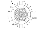
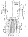
- FIG. 4 is a cross-sectional view taken along the line IV-IV in FIG. 3, as viewed from the downstream side. It is a flowchart explaining the control method of the combustor of 1st embodiment of this invention. It is detail drawing of the combustor of 2nd embodiment of this invention. It is detail drawing of the combustor of 3rd embodiment of this invention.
- the power generation system 1 of the present embodiment includes a gasification furnace 11, a gas purification device 12, an oxygen production device 13, a gas turbine 14 including a combustor 22, and a driving force of the gas turbine 14.
- This is a combined power generation system including a first generator 15 that generates electric power, an exhaust heat recovery boiler 16 (HRSG), a steam turbine 17, and a second generator 18.
- HRSG exhaust heat recovery boiler 16
- the gasifier 11 incompletely burns pulverized coal (coal) as a solid fuel to generate unburned gas (H 2 , CO, CO 2 , N 2, etc.).
- the gas purifier 12 purifies the gas fuel F (H 2 , CO) by removing impurities by performing a purification process or the like from the unburned gas generated in the gasification furnace 11. That is, by passing the unburned gas generated in the gasification furnace 11 through various devices of the gas purification device 12, it is possible to remove sulfur compounds, nitrogen compounds, and other harmful substances by their own heat.
- the gasification furnace 11 may be configured to gasify the liquid fuel.
- the oxygen production device 13 produces high concentration pure oxygen from the atmosphere.
- the oxygen production apparatus 13 is, for example, a technique such as a cryogenic fractionation (liquefaction fractionation), a pressure sweep adsorption (PSA) method using a zeolite adsorbent, or a pressure sweep adsorption (PSA) method using a carbon molecular sieve. It is possible to employ a device using
- the gas turbine 14 includes a compressor 21, a combustor 22, and a turbine 23.
- the compressor 21 and the turbine 23 are connected via a turbine shaft 24.
- the gas turbine 14 and the first generator 15 are connected via a turbine shaft 24.
- the compressor 21 and the combustor 22 of the gas turbine 14 are connected by an exhaust circulation gas supply line 25.
- the combustor 22 and the gas purification device 12 are connected by a gas fuel supply line 26.
- the combustor 22 and the oxygen production device 13 are connected by an oxygen supply line 27.
- the combustor 22 and the turbine 23 are connected by a combustion gas supply line 28.
- the exhaust heat recovery boiler 16 includes, for example, a high pressure boiler, an intermediate pressure boiler, and a low pressure boiler.
- the exhaust heat recovery boiler 16 can generate steam in each boiler by the exhaust gas discharged from the gas turbine 14.
- the turbine 23 and the exhaust heat recovery boiler 16 are connected by an exhaust gas discharge line 29.
- Exhaust gas E (CO 2 + H 2 O) discharged from the turbine 23 is introduced into the exhaust gas discharge line 29.
- the exhaust heat recovery boiler 16 and the compressor 21 of the gas turbine 14 are connected by an exhaust gas return line 30.
- An exhaust gas recovery line 31 branches from the exhaust gas return line 30.
- the steam turbine 17 is driven by the supply of steam generated in the exhaust heat recovery boiler 16, and can operate the connected second generator 18.
- the steam supplied to the steam turbine 17 is sent to a condenser (not shown) and condensed, and then sent to the exhaust heat recovery boiler 16 by a condensate pump.
- the gas turbine 14 and the steam turbine 17 may be arranged on the same axis, and one generator may be shared.
- the exhaust gas supply line 25, the combustion gas supply line 28, the exhaust gas discharge line 29, and the exhaust gas return line 30 constitute the exhaust gas E circulation path.
- the gas discharged from the turbine 23 is referred to as exhaust gas E.
- the gas compressed by the compressor 21 and supplied to the combustor 22 by the exhaust circulation gas supply line 25 is referred to as exhaust circulation gas E.
- the exhaust gas E and the exhaust gas circulation E are different in temperature and pressure, but are the same quality.
- the exhaust gas E and the exhaust circulation gas E function as an inert gas.
- the operation of the power generation system 1 of the present embodiment will be described.
- oxygen, nitrogen, and pulverized coal are supplied, and the pulverized coal is combusted inside to generate unburned gas.
- the unburned gas is cooled by a heat exchanger and then char is removed.
- the gas purification device 12 removes sulfur compounds, nitrogen compounds, and other harmful substances, and the gas fuel F is purified.
- the exhaust gas E taken into the compressor 21 through the exhaust gas return line 30 is compressed to become high-temperature and high-pressure compressed gas (exhaust circulation gas E).
- the compressed gas is sent to the combustor 22 via the exhaust gas supply line 25 as the exhaust gas E.
- the gas fuel F purified by the gas purification device 12 is sent to the combustor 22 through the gas fuel supply line 26, and oxygen (O 2 ) produced by the oxygen production device 13 is passed through the oxygen supply line 27. Sent to.
- the mixed gas of the exhaust circulation gas E, the gas fuel F, and oxygen is ignited and burned.
- the high-temperature and high-pressure combustion gas generated in the combustor 22 is sent to the turbine 23 via the combustion gas supply line 28 and passes through a plurality of stationary blades and moving blades (not shown) to drive and rotate the turbine shaft 24. .
- the 1st generator 15 act operates and electric power generation is performed.
- the exhaust gas E discharged from the turbine 23 is sent to the exhaust heat recovery boiler 16 through the exhaust gas discharge line 29.
- steam is generated by the high-temperature and high-pressure exhaust gas E.
- the generated steam is sent to the steam turbine 17, and by driving the steam turbine 17, the second generator 18 is operated to generate power.
- the exhaust gas recovered by the exhaust heat recovery boiler 16 is returned to the compressor 21 via the exhaust gas return line 30, and a part is recovered through the exhaust gas recovery line 31.
- the exhaust gas E, the gas fuel F, and oxygen are supplied to the combustor 22 and burned. Therefore, it is necessary to mix gas fuel F and oxygen sufficiently and burn them efficiently.
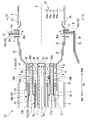
- the combustor 22 includes an inner cylinder 2, an outer cylinder 3, a combustion cylinder 4, a pilot nozzle 5 and a main nozzle 6 (fuel supply unit), a scoop 7, and a plurality of oxygen supply units. 32, a CO concentration measurement device 10, an analysis unit 19, and an adjustment unit 20.
- the inner cylinder 2 has a cylindrical shape with the axis A as the center.
- the outer cylinder 3 is provided coaxially with the axis A of the inner cylinder 2 on the outer peripheral side of the inner cylinder 2.
- the combustion cylinder 4 is connected to the downstream side Da2 of the inner cylinder 2 and further extends to the downstream side Da2.
- the pilot nozzle 5 and the main nozzle 6 are disposed in the inner cylinder 2.
- the scoop 7 is formed so as to penetrate the combustion cylinder 4.
- the plurality of oxygen supply units 32 supplies oxygen into the combustion cylinder 4.
- the CO concentration measuring device 10 g measures the CO concentration of the combustion gas flowing through the combustion cylinder 4.
- the analysis unit 19 analyzes the CO concentration measured by the CO concentration measurement device 10.
- the adjustment unit 20 adjusts the oxygen supply amount supplied to the oxygen supply unit 32 based on the result analyzed by the analysis unit 19.
- the direction in which the axis A of the inner cylinder 2 extends is defined as the axis direction Da.
- the direction orthogonal to the axis A is the radial direction.
- the side away from the axis A in the radial direction is referred to as the radially outer side.
- the side approaching the axis A in the radial direction is referred to as the radial inner side.
- the left side of FIGS. 2 and 3 is referred to as an upstream side Da1
- the right side of FIGS. 2 and 3 is referred to as a downstream side Da2.
- oxygen is indicated by a solid line arrow
- the exhaust circulation gas E is indicated by a one-dot chain line arrow
- the gas fuel F is indicated by a two-dot chain line arrow.
- an exhaust circulation gas flow path R for introducing the exhaust circulation gas E so as to be reversed at the end 2a of the inner cylinder 2 toward the downstream Da2. That is, the exhaust gas circulation gas E is introduced into the exhaust gas circulation gas channel R through the exhaust gas circulation gas supply line 25.
- the exhaust gas E that has flowed into the combustor 22 from between the outer cylinder 3 and the combustion cylinder 4 turns 180 ° at the end wall of the outer cylinder 3 (not shown) and is supplied to the inside of the inner cylinder 2 (main nozzle 6). Is done.
- the combustion cylinder 4 has a cylindrical shape centered on the axis A, and has a plurality of openings 33 through which the exhaust circulation gas E flows on the downstream side Da2.
- the exhaust gas E flowing from the opening 33 functions as a film fluid.
- the scoop 7 is a tubular member that penetrates the outer peripheral surface of the combustion cylinder 4 from the radially outer side toward the center of the combustion cylinder 4.
- Four scoops 7 are provided at equal intervals in the circumferential direction.
- the number of scoops 7 is not limited to this, and may be eight, for example.
- the pilot nozzle 5 is provided on the upstream side Da ⁇ b> 1 of the combustion cylinder 4 along the axis A of the inner cylinder 2.
- the pilot nozzle 5 injects the gas fuel F supplied from the gas purification device 12 from the tip side to the downstream Da2, and ignites the gas fuel F to generate a flame. That is, a part of the gas fuel F introduced into the combustor 22 through the gas fuel supply line 26 is supplied to the pilot nozzle 5.
- the main nozzle 6 is a ring-shaped nozzle that is provided on the radially inner side of the inner cylinder 2 and on the radially outer side of the pilot nozzle 5 and is coaxial with the inner cylinder 2.
- the combustor 22 includes four systems of oxygen supply units 32 including an inner peripheral oxygen supply unit 32a, an outer peripheral oxygen supply unit 32b, a scoop oxygen supply unit 32c, and a pilot nozzle oxygen supply unit 32d.
- the inner peripheral oxygen supply unit 32 a supplies oxygen to the radially inner side of the main nozzle 6.
- the outer peripheral oxygen supply unit 32 b supplies oxygen to the radially outer side of the main nozzle 6.
- the scoop oxygen supply unit 32 c supplies oxygen to the scoop 7.
- the pilot nozzle oxygen supply unit 32 d supplies oxygen to the pilot nozzle 5.
- the oxygen supply line 27 into which oxygen is introduced from the oxygen production apparatus 13 is branched into four.
- the inner peripheral side oxygen supply part 32a has the inner peripheral side nozzle 37a (refer FIG. 3) connected to the 1st oxygen supply line 27a.
- the outer periphery side oxygen supply part 32b has the outer periphery side nozzle 37b (refer FIG. 3) connected to the 2nd oxygen supply line 27b.
- the scoop oxygen supply unit 32c has a scoop nozzle 38 (see FIG. 3) connected to the third oxygen supply line 27c.
- the pilot nozzle oxygen supply part 32d has the pilot nozzle 5 connected to the fourth oxygen supply line 27d. That is, the pilot nozzle 5 functions as the oxygen supply unit 32.
- the first oxygen supply line 27a is provided with a first adjustment valve 42a for adjusting the flow rate of oxygen flowing through the first oxygen supply line 27a.
- the second oxygen supply line 27b is provided with a second adjustment valve 42b for adjusting the flow rate of oxygen flowing through the second oxygen supply line 27b.
- the third oxygen supply line 27c is provided with a third adjustment valve 42c for adjusting the flow rate of oxygen flowing through the third oxygen supply line 27c.
- the fourth oxygen supply line 27d is provided with a fourth adjustment valve 42d for adjusting the flow rate of oxygen flowing through the fourth oxygen supply line 27d.
- the gas fuel F supplied from the gas purification device 12 is introduced into the pilot nozzle 5 and the main nozzle 6.
- the exhaust circulation gas E supplied from the exhaust circulation gas supply line 25 is introduced into the exhaust circulation gas flow path R and the scoop 7.
- the exhaust circulation gas E is introduced from the scoop 7 to the center of the combustion cylinder 4 and flows forward and backward (upstream Da1 and downstream Da2) in the flow direction of the combustion gas.
- the main nozzle 6 of the present embodiment includes a first ring 8 that is an annular member provided on the radially outer side of the pilot nozzle 5 and an annular member provided on the radially outer side of the first ring 8. And a second ring 9 which is a member.
- An inner circumferential space 34 a into which the exhaust gas circulation gas E, which is an inert gas, is introduced is defined between the pilot nozzle 5 and the first ring 8 on the radially inner side of the main nozzle 6.
- An outer peripheral side space 34 b into which the exhaust gas circulation gas E that is an inert gas is introduced is defined between the second ring 9 and the inner cylinder 2 outside the main nozzle 6 in the radial direction. That is, a part of the exhaust circulation gas E supplied from the exhaust circulation gas supply line 25 is divided into an inner peripheral space 34 a radially inside the main nozzle 6 and an outer peripheral space 34 b radially outside the main nozzle 6. After being introduced, it is supplied to the combustion cylinder 4.
- a swirler 36 (swirl blade) is provided in the inner peripheral space 34a and the outer peripheral space 34b. The swirler 36 applies a turning force to the flow in the inner circumferential side space 34a and the outer circumferential side space 34b.
- the radial width of the inner peripheral space 34a of the present embodiment is larger than the radial width of the outer peripheral space 34b.
- the main nozzle 6 is provided between the first ring 8 and the second ring 9 and has a fuel injection nozzle portion 35 for injecting the gaseous fuel F.
- a plurality of fuel injection holes 35 a are formed at the tip of the fuel injection nozzle portion 35. That is, part of the gas fuel F supplied from the gas fuel supply line 26 is introduced into the fuel injection nozzle portion 35.
- the fuel injection nozzle portion 35 functions as a fuel supply portion that supplies the gas fuel F into the combustion cylinder 4.
- a plurality of fuel injection holes 5 a and a plurality of oxygen injection holes 5 b are formed at the tip of the pilot nozzle 5. As shown in FIG. 4, the plurality of fuel injection holes 5 a are formed at intervals in the circumferential direction with the axis A as the center. The plurality of oxygen injection holes 5b are formed on the radially inner side of the plurality of fuel injection holes 5a at intervals in the circumferential direction.
- the inner peripheral oxygen supply part 32a has an inner peripheral nozzle 37a extending from the downstream Da2 toward the upstream Da1 between the main nozzle 6 and the pilot nozzle 5 (a radial gap). .
- the inner circumferential side nozzle 37 a is a cylindrical nozzle disposed in the inner circumferential side space 34 a between the main nozzle 6 and the pilot nozzle 5.
- the inner peripheral nozzle 37a is connected to the first oxygen supply line 27a.
- a plurality of inner peripheral oxygen injection holes 40a are formed at the tip of the inner peripheral nozzle 37a.
- the inner circumferential side oxygen injection hole 40a (the tip of the inner circumferential side nozzle 37a) is disposed on the upstream side Da1 from the swirler 36.
- the outer peripheral oxygen supply unit 32b includes an outer peripheral nozzle 37b extending from the downstream Da2 toward the upstream Da1 between the main nozzle 6 and the inner cylinder 2 (a radial gap).
- the outer peripheral side nozzle 37 b is a cylindrical nozzle disposed in the outer peripheral side space 34 b between the main nozzle 6 and the inner cylinder 2.
- the outer peripheral side nozzle 37b is connected to the second oxygen supply line 27b.
- a plurality of outer peripheral oxygen injection holes 40b are formed at the tip of the outer peripheral nozzle 37b.
- the outer peripheral oxygen injection hole 40b (the tip of the outer peripheral nozzle 37b) is disposed on the upstream Da1 side from the swirler 36.
- the scoop oxygen supply unit 32 c has a scoop nozzle 38 that extends along the central axis of the scoop 7 on the inner peripheral side of the scoop 7. Similar to the scoop 7, the scoop nozzle 38 is formed so as to penetrate the combustion cylinder 4. An oxygen injection hole 40 c is formed at the tip of the scoop nozzle 38. Oxygen injected from the oxygen injection hole 40 c of the scoop nozzle 38 is introduced into the center of the combustion cylinder 4 together with the exhaust circulation gas E introduced through the scoop 7.
- the pilot nozzle 5 functions as the oxygen supply unit 32. That is, oxygen supplied to the pilot nozzle 5 via the fourth oxygen supply line 27d is injected from the oxygen injection hole 5b formed at the tip of the pilot nozzle 5. The oxygen introduced into the pilot nozzle 5 via the fourth oxygen supply line 27d is supplied from the radial center of the upstream side Da1 of the combustion cylinder 4 toward the downstream Da2.
- the CO concentration measuring device 10 is a device that measures the CO concentration (carbon monoxide concentration) of the combustion gas flowing through the combustion cylinder 4.
- the CO concentration measuring device 10 is attached to the inner peripheral surface of the combustion cylinder 4.
- the CO concentration measuring apparatus 10 has a plurality of measurement points 10a that are spaced apart in the radial direction.
- the measurement points 10a are disposed at least near the center in the radial direction of the combustion cylinder 4 and radially outside the combustion cylinder 4 (near the inner peripheral surface of the combustion cylinder 4).
- the CO concentration measurement device 10 is electrically connected to the analysis unit 19.
- the analyzing unit 19 analyzes the CO concentration of the combustion gas measured by the CO concentration measuring device 10.
- the analysis unit 19 can calculate, for example, a difference D between the CO concentration at the center of the combustion cylinder 4 and the CO concentration at the radially outer side.
- the analysis unit 19 and the adjustment unit 20 are electrically connected. Moreover, the adjustment part 20 and the 1st adjustment valve 42a are electrically connected, and the adjustment part 20 and the 2nd adjustment valve 42b are electrically connected.
- the adjustment unit 20 adjusts the opening degrees of the first adjustment valve 42a and the second adjustment valve 42b based on the difference D between the CO concentration at the center of the combustion cylinder 4 calculated by the analysis unit 19 and the CO concentration on the radially outer side. It has a function to do. That is, the adjustment unit 20 has a function of adjusting the relative amount of oxygen supplied from the inner peripheral oxygen supply unit 32a and oxygen supplied from the outer peripheral oxygen supply unit 32b.
- the adjustment unit 20 determines whether or not the difference D is within a predetermined value. If the difference D is not within the predetermined value, the adjustment unit 20 adjusts the opening degrees of the first adjustment valve 42a and the second adjustment valve 42b. Specifically, when the difference D is not within the predetermined value and the CO concentration in the central portion is higher than the radially outer CO concentration, the adjustment unit 20 sets the oxygen supply amount of the inner peripheral oxygen supply unit 32a. The opening degree of the first adjustment valve 42a and the second adjustment valve 42b is adjusted so as to increase and decrease the oxygen supply amount of the outer peripheral oxygen supply unit 32b.
- the adjusting unit 20 decreases the oxygen supply amount of the inner peripheral oxygen supply unit 32a and the oxygen supply amount of the outer peripheral oxygen supply unit 32b.
- the degree of opening of the first adjustment valve 42a and the second adjustment valve 42b is adjusted so as to increase.
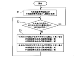
- the combustor control method includes an oxygen supply step S1, a concentration difference determination step S2, and an oxygen supply amount change step S3.
- oxygen is supplied from the inner peripheral oxygen supply part 32a and the outer peripheral oxygen supply part 32b.
- concentration difference determination step S2 it is determined whether the difference D between the CO concentration at the center of the combustion cylinder 4 and the CO concentration at the radially outer side is within a predetermined value.
- oxygen supply amount changing step S3 the oxygen supply amount is changed when the difference D is not within a predetermined value.
- oxygen is supplied from the inner peripheral oxygen supply part 32a and the outer peripheral oxygen supply part 32b.
- the oxygen supply amount supplied from the inner peripheral side oxygen supply part 32a and the oxygen supply amount supplied from the outer peripheral side oxygen supply part 32b can be made equal.
- the concentration difference determination step S2 when the difference D between the CO concentration at the center of the combustion cylinder 4 and the CO concentration outside in the radial direction is within a predetermined value, the oxygen supply is continued as it is. On the other hand, when the difference D is not within the predetermined value, the oxygen supply amount changing step S3 is executed.
- the oxygen supply amount changing step S3 when the CO concentration in the central portion is higher than the CO concentration on the radially outer side, the oxygen supply amount of the inner peripheral oxygen supply portion 32a is increased and the oxygen supply of the outer peripheral oxygen supply portion 32b is increased.
- the opening degree of the first adjustment valve 42a and the second adjustment valve 42b is adjusted so as to decrease the amount. Further, when the CO concentration in the central portion is lower than the CO concentration on the outer side in the radial direction, the oxygen supply amount of the inner peripheral side oxygen supply unit 32a is decreased, and the oxygen supply amount of the outer peripheral side oxygen supply unit 32b is increased.
- the opening degree of the first adjustment valve 42a and the second adjustment valve 42b is adjusted. By these controls, the CO concentration in the combustion cylinder 4 can be made uniform.
- the gas fuel F and oxygen are injected from the main nozzle 6.
- the exhaust circulation gas E and oxygen are injected from the inner circumferential space 34a and the outer circumferential space 34b.
- Gas fuel F and oxygen are injected from the pilot nozzle 5.
- Exhaust gas E and oxygen are injected from the scoop 7 toward the center. Therefore, the gas fuel F and oxygen are mixed and ignited in the space sandwiched by the exhaust gas circulation E. As a result, sufficient mixing is possible, and a flame surface FL (see FIG. 2) is formed at an appropriate position to efficiently burn.
- the gas fuel F injected from the fuel injection nozzle portion 35 of the main nozzle 6 is supplied radially outward from the exhaust circulation gas E supplied from the scoop 7. Further, oxygen injected from the nozzles 37a and 37b is introduced into the main nozzle 6 and then mixed with the exhaust circulation gas E in the inner peripheral space 34a and the outer peripheral space 34b. This air-fuel mixture is supplied radially outward from the exhaust circulation gas E supplied to the center of the combustion cylinder 4 via the scoop 7.
- the relative amount of oxygen supplied to the inner peripheral space 34a and oxygen supplied to the outer peripheral space 34b is adjusted. Therefore, it is possible to approach an oxygen concentration that is more suitable for the combustion state of the fuel. Thereby, CO concentration in combustion gas can be reduced.
- the adjustment unit 20 individually adjusts the oxygen supply amount supplied from the inner peripheral oxygen supply unit 32a and the oxygen supply amount supplied from the outer peripheral oxygen supply unit 32b. Thereby, the optimal oxygen concentration according to the combustion state of the fuel can be set.
- the gas fuel F and oxygen are supplied adjacent to the outside of the exhaust circulation gas E (inert gas) supplied to the central portion in the combustion cylinder 4. Therefore, the mixing of the gas fuel F and oxygen is good. Thereby, the utilization rate of oxygen by combustion can be brought close to 100%. Therefore, the residual oxygen in the exhaust gas E can be suppressed and the combustion efficiency can be improved.
- oxygen is supplied from the scoop 7 through the scoop nozzle 38, and oxygen is supplied in two stages. Thereby, reduction of combustion gas temperature and radiation intensity can be aimed at. Furthermore, even when the gaseous fuel F contains a nitrogen component, the production of NOx can be suppressed.
- pilot nozzle 5 as the oxygen supply part 32 that supplies oxygen from the radial center of the upstream side Da1 of the combustion cylinder 4 toward the downstream side Da2, oxygen is supplied in three stages. Thereby, further reduction of combustion gas temperature and radiation intensity can be aimed at.
- oxygen is supplied from the tip of the pilot nozzle 5. Thereby, the flame holding property at the time of starting of the gas turbine 14 can be improved.
- the exhaust gas E that is an inert gas contains carbon dioxide. By circulating this exhaust gas E, the amount of carbon dioxide emission can be suppressed.
- the oxygen supply amount supplied from the inner peripheral oxygen supply unit 32a and the oxygen supply amount supplied from the outer peripheral oxygen supply unit 32b are individually adjusted. There is no.
- the second adjustment valve 42b may be eliminated, and the relative amount of oxygen supplied to the inner peripheral space 34a and oxygen supplied to the outer peripheral space 34b may be adjusted using only the first adjustment valve 42a.
- the inner peripheral side nozzle 37a (inner peripheral side oxygen injection hole 40a) of the present embodiment is installed at a position biased toward the main nozzle 6 in the radial direction.
- the inner peripheral side nozzle 37a of the present embodiment is disposed as far as possible in the radial direction.
- the outer peripheral side nozzle 37b (outer peripheral side oxygen injection hole 40b) of the present embodiment is installed at a position biased toward the main nozzle 6 side.
- the outer peripheral side nozzle 37b of the present embodiment is arranged on the radially inner side as much as possible.
- the oxygen concentration on the main nozzle 6 side that is the fuel supply unit is increased. Therefore, the combustion of fuel is promoted, and the CO concentration in the combustion gas can be further reduced.
- FIG. 7 the position in the axial direction of the inner peripheral oxygen injection hole 40 a and the position in the axial direction of the outer peripheral oxygen injection hole 40 b in the present embodiment are different. Specifically, the position in the axial direction of the inner peripheral oxygen injection hole 40a is arranged on the downstream side Da2 with respect to the position in the axial direction of the outer peripheral oxygen injection hole 40b.
- the combustibility of the gas fuel F and oxygen is activated on the inner peripheral side and the flame holding property is improved, and the flame temperature is suppressed on the outer peripheral side. Therefore, the temperature rise on the wall surface side of the combustion cylinder 4 can be suppressed.
- the position of the inner peripheral oxygen injection hole 40a in the axial direction is disposed on the downstream side Da2 relative to the position of the outer peripheral oxygen injection hole 40b in the axial direction.
- the present invention is not limited to this.
- the mixing distance between the exhaust gas circulation and the oxygen the oxygen mixing at the nozzle outlet can be distributed.
- the oxygen concentration can be brought closer to a more suitable state in accordance with the combustion state of the fuel. Thereby, CO concentration in combustion gas can be reduced.
Landscapes
- Engineering & Computer Science (AREA)
- Chemical & Material Sciences (AREA)
- Combustion & Propulsion (AREA)
- Mechanical Engineering (AREA)
- General Engineering & Computer Science (AREA)
Priority Applications (1)
| Application Number | Priority Date | Filing Date | Title |
|---|---|---|---|
| US16/980,904 US11346556B2 (en) | 2018-03-20 | 2019-03-18 | Combustor having inner and outer tubular oxygen nozzles about a tubular fuel supply unit |
Applications Claiming Priority (2)
| Application Number | Priority Date | Filing Date | Title |
|---|---|---|---|
| JP2018-053512 | 2018-03-20 | ||
| JP2018053512A JP6956035B2 (ja) | 2018-03-20 | 2018-03-20 | 燃焼器 |
Publications (1)
| Publication Number | Publication Date |
|---|---|
| WO2019181877A1 true WO2019181877A1 (ja) | 2019-09-26 |
Family
ID=67987832
Family Applications (1)
| Application Number | Title | Priority Date | Filing Date |
|---|---|---|---|
| PCT/JP2019/011252 Ceased WO2019181877A1 (ja) | 2018-03-20 | 2019-03-18 | 燃焼器 |
Country Status (3)
| Country | Link |
|---|---|
| US (1) | US11346556B2 (https=) |
| JP (1) | JP6956035B2 (https=) |
| WO (1) | WO2019181877A1 (https=) |
Families Citing this family (7)
| Publication number | Priority date | Publication date | Assignee | Title |
|---|---|---|---|---|
| US11248789B2 (en) | 2018-12-07 | 2022-02-15 | Raytheon Technologies Corporation | Gas turbine engine with integral combustion liner and turbine nozzle |
| WO2022181694A1 (ja) | 2021-02-25 | 2022-09-01 | 三菱パワー株式会社 | 燃焼器用筒、燃焼器、及びガスタービン |
| US11725824B2 (en) * | 2021-04-08 | 2023-08-15 | Raytheon Technologies Corporation | Turbulence generator mixer for rotating detonation engine |
| US11846426B2 (en) | 2021-06-24 | 2023-12-19 | General Electric Company | Gas turbine combustor having secondary fuel nozzles with plural passages for injecting a diluent and a fuel |
| CN114353121B (zh) * | 2022-01-18 | 2022-12-20 | 上海交通大学 | 一种用于燃气轮机的多喷嘴燃料注入方法 |
| CN117588753B (zh) * | 2023-11-21 | 2025-12-26 | 清华大学 | 一种掺氨燃料多级微分解旋流燃烧器及低NOx控制方法 |
| US20260078905A1 (en) * | 2024-09-17 | 2026-03-19 | General Electric Company | Turbine engine with combustion section and fuel passage that supplies hydrogen-containing fuel to combustion section |
Citations (3)
| Publication number | Priority date | Publication date | Assignee | Title |
|---|---|---|---|---|
| JP2008249187A (ja) * | 2007-03-29 | 2008-10-16 | Hitachi Ltd | 火力発電プラントの制御装置、及び火力発電プラントの制御方法 |
| JP2011094573A (ja) * | 2009-10-30 | 2011-05-12 | Mitsubishi Heavy Ind Ltd | ガスタービン燃焼器及び発電システム |
| JP2016505101A (ja) * | 2012-11-02 | 2016-02-18 | エクソンモービル アップストリーム リサーチ カンパニー | 化学量論的排気ガス再循環ガスタービンシステム内の拡散燃焼のためのシステム及び方法 |
Family Cites Families (8)
| Publication number | Priority date | Publication date | Assignee | Title |
|---|---|---|---|---|
| US6684641B2 (en) | 1999-12-15 | 2004-02-03 | Osaka Gas Co., Ltd. | Fluid distributor, burner device, gas turbine engine, and cogeneration system |
| JP4508474B2 (ja) * | 2001-06-07 | 2010-07-21 | 三菱重工業株式会社 | 燃焼器 |
| JP2007262951A (ja) | 2006-03-28 | 2007-10-11 | Jfe Steel Kk | ガスタービン発電装置の運転方法およびその装置 |
| US9719419B2 (en) * | 2011-03-16 | 2017-08-01 | Mitsubishi Heavy Industries, Ltd. | Gas turbine combustor with top hat nozzle arrangements |
| JP6004976B2 (ja) * | 2013-03-21 | 2016-10-12 | 三菱重工業株式会社 | 燃焼器及びガスタービン |
| US9835089B2 (en) * | 2013-06-28 | 2017-12-05 | General Electric Company | System and method for a fuel nozzle |
| JP6934359B2 (ja) * | 2017-08-21 | 2021-09-15 | 三菱パワー株式会社 | 燃焼器及びその燃焼器を備えるガスタービン |
| JP6995696B2 (ja) * | 2018-05-28 | 2022-01-17 | 三菱重工業株式会社 | 燃料噴射装置及びガスタービン |
-
2018
- 2018-03-20 JP JP2018053512A patent/JP6956035B2/ja active Active
-
2019
- 2019-03-18 WO PCT/JP2019/011252 patent/WO2019181877A1/ja not_active Ceased
- 2019-03-18 US US16/980,904 patent/US11346556B2/en active Active
Patent Citations (3)
| Publication number | Priority date | Publication date | Assignee | Title |
|---|---|---|---|---|
| JP2008249187A (ja) * | 2007-03-29 | 2008-10-16 | Hitachi Ltd | 火力発電プラントの制御装置、及び火力発電プラントの制御方法 |
| JP2011094573A (ja) * | 2009-10-30 | 2011-05-12 | Mitsubishi Heavy Ind Ltd | ガスタービン燃焼器及び発電システム |
| JP2016505101A (ja) * | 2012-11-02 | 2016-02-18 | エクソンモービル アップストリーム リサーチ カンパニー | 化学量論的排気ガス再循環ガスタービンシステム内の拡散燃焼のためのシステム及び方法 |
Also Published As
| Publication number | Publication date |
|---|---|
| US11346556B2 (en) | 2022-05-31 |
| JP6956035B2 (ja) | 2021-10-27 |
| US20210025323A1 (en) | 2021-01-28 |
| JP2019163757A (ja) | 2019-09-26 |
Similar Documents
| Publication | Publication Date | Title |
|---|---|---|
| WO2019181877A1 (ja) | 燃焼器 | |
| US11371710B2 (en) | Gas turbine combustor assembly with a trapped vortex feature | |
| RU2457397C2 (ru) | Смеситель топлива с воздухом для камер сгорания | |
| AU2013337647B8 (en) | System and method for load control with diffusion combustion in a stoichiometric exhaust gas recirculation gas turbine system | |
| US8099960B2 (en) | Triple counter rotating swirler and method of use | |
| US20100170253A1 (en) | Method and apparatus for fuel injection in a turbine engine | |
| JP2008096099A (ja) | ガスタービンエンジン排出物を低減する方法及び装置 | |
| KR101774630B1 (ko) | 가스 터빈 엔진에 사용되는 예비혼합된 연료와 공기를 가진 접선방향의 애뉼러형 연소실 | |
| WO2015166597A1 (ja) | ガスタービン燃焼器、ガスタービン、制御装置及び制御方法 | |
| KR101774094B1 (ko) | 가스 터빈 엔진에서 사용되는 예비혼합형 접선방향 연료-공기 노즐을 가진 캔-애뉼러형 연소실 | |
| KR20140082658A (ko) | 가스 터빈 엔진에서 사용되는 스테이지가 형성되고 접선방향으로 형성된 연료-공기 노즐을 가진 캔-애뉼러형 연소실 | |
| JP2015132462A (ja) | 希釈ガスを用いる2段燃焼配列 | |
| US9453646B2 (en) | Method for air entry in liner to reduce water requirement to control NOx | |
| JP7023051B2 (ja) | ガスタービン燃焼器及び発電システム | |
| EP2119966A1 (en) | Combustor with reduced carbon monoxide emissions | |
| US10316746B2 (en) | Turbine system with exhaust gas recirculation, separation and extraction | |
| JP5627831B2 (ja) | タービンエンジン内に流体を噴射するための装置 | |
| US10253690B2 (en) | Turbine system with exhaust gas recirculation, separation and extraction | |
| EP2104803B1 (en) | Gas-turbine burner that uses, as fuel, gas with low calorific value | |
| US20130160856A1 (en) | Multi-port injector system and method | |
| TW201441479A (zh) | 化學計量廢氣再循環燃氣渦輪系統中之以擴散燃燒進行負載控制之系統及方法 |
Legal Events
| Date | Code | Title | Description |
|---|---|---|---|
| 121 | Ep: the epo has been informed by wipo that ep was designated in this application |
Ref document number: 19771079 Country of ref document: EP Kind code of ref document: A1 |
|
| NENP | Non-entry into the national phase |
Ref country code: DE |
|
| 122 | Ep: pct application non-entry in european phase |
Ref document number: 19771079 Country of ref document: EP Kind code of ref document: A1 |