WO2019181237A1 - ドアハンドル - Google Patents
ドアハンドル Download PDFInfo
- Publication number
- WO2019181237A1 WO2019181237A1 PCT/JP2019/003710 JP2019003710W WO2019181237A1 WO 2019181237 A1 WO2019181237 A1 WO 2019181237A1 JP 2019003710 W JP2019003710 W JP 2019003710W WO 2019181237 A1 WO2019181237 A1 WO 2019181237A1
- Authority
- WO
- WIPO (PCT)
- Prior art keywords
- detection electrode
- electrode
- door handle
- capacitance
- door
- Prior art date
- Legal status (The legal status is an assumption and is not a legal conclusion. Google has not performed a legal analysis and makes no representation as to the accuracy of the status listed.)
- Ceased
Links
Images








Classifications
-
- B—PERFORMING OPERATIONS; TRANSPORTING
- B60—VEHICLES IN GENERAL
- B60J—WINDOWS, WINDSCREENS, NON-FIXED ROOFS, DOORS, OR SIMILAR DEVICES FOR VEHICLES; REMOVABLE EXTERNAL PROTECTIVE COVERINGS SPECIALLY ADAPTED FOR VEHICLES
- B60J5/00—Doors
-
- E—FIXED CONSTRUCTIONS
- E05—LOCKS; KEYS; WINDOW OR DOOR FITTINGS; SAFES
- E05B—LOCKS; ACCESSORIES THEREFOR; HANDCUFFS
- E05B81/00—Power-actuated vehicle locks
- E05B81/54—Electrical circuits
- E05B81/64—Monitoring or sensing, e.g. by using switches or sensors
- E05B81/76—Detection of handle operation; Detection of a user approaching a handle; Electrical switching actions performed by door handles
-
- E—FIXED CONSTRUCTIONS
- E05—LOCKS; KEYS; WINDOW OR DOOR FITTINGS; SAFES
- E05B—LOCKS; ACCESSORIES THEREFOR; HANDCUFFS
- E05B85/00—Details of vehicle locks not provided for in groups E05B77/00 - E05B83/00
- E05B85/10—Handles
- E05B85/14—Handles pivoted about an axis parallel to the wing
- E05B85/16—Handles pivoted about an axis parallel to the wing a longitudinal grip part being pivoted at one end about an axis perpendicular to the longitudinal axis of the grip part
Definitions
- the present invention relates to a door handle.
- a door of an automobile or the like is provided with a door handle for opening and closing the door.
- a door can be locked or unlocked by performing a gesture operation by bringing a hand close to the door handle. What can be done has also appeared.
- Such a door handle is provided with an electrostatic sensor or the like for detecting a hand operation.
- the locking electrostatic sensor for locking the door is installed inside the door handle case.
- the finger of a human hand approaches the door handle and is detected by the locking electrostatic sensor, the door is moved. Locked.
- the electrostatic lock sensor since the electrostatic lock sensor is placed inside the door handle case, the exact position cannot be determined from the outside, and the finger of the hand approaches the wiring connected to the electrostatic lock sensor. Even in this case, the door may be locked. For example, when you try to unlock the door and you bring your hand close to the unlocking electrostatic sensor on the door handle, the finger of your hand gets close to the wiring connected to the locking electrostatic sensor. Will lock the door.
- a door handle that can prevent a false detection that an operation unintended by the user such as the door being locked is performed, and can detect a lock operation only when the door is desired to be locked. Is required.
- a door handle case a detection electrode installed in the door handle case, and the vicinity of the detection electrode or the detection electrode in the door handle case
- An auxiliary electrode installed so as to cover a part
- a control unit connected to the detection electrode and the auxiliary electrode, wherein the detection electrode and the auxiliary electrode measure a capacitance with an operating body.
- the control unit performs an operation by the operating body based on the first capacitance detected at the detection electrode and the second capacitance detected at the auxiliary electrode. It is characterized by judging.
- the disclosed door handle it is possible to prevent a false detection that an operation unintended by the user such as the door is locked when the door is unlocked, and the lock operation is performed only when the door is desired to be locked. Can be detected.
- the X1-X2 direction, the Y1-Y2 direction, and the Z1-Z2 direction are directions orthogonal to each other.
- a plane including the X1-X2 direction and the Y1-Y2 direction is referred to as an XY plane
- a plane including the Y1-Y2 direction and the Z1-Z2 direction is referred to as a YZ plane
- the Z1-Z2 direction and the X1-X2 direction are referred to as YZ plane.
- the plane including the surface is referred to as a ZX plane.
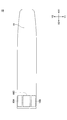
- FIGS. 1 is a perspective view of the door handle 10, FIG. 2 is a top view, and FIG. 3 is a front view.
- FIG. 4 is a front view of the first door handle case 11 removed, and
- FIG. 5 is a perspective view.
- the door handle 10 is attached to the outside of a vehicle door such as an automobile.
- a door handle case serving as a housing portion of the door handle 10 is formed by a first door handle case 11 and a second door handle case 12, and the first door handle case 11 and the second door handle case 12 are formed.
- the door handle 10 is formed by covering the electrostatic sensor 100. Therefore, the electrostatic sensor 100 is provided inside the door handle 10.
- the central portion of the inner surface 12a of the second door handle case 12 is recessed toward the Z1 side so that it can be easily gripped by a human hand.
- the second door handle case 12 is provided with a through hole 13 for passing the wiring 113 connected to the electrostatic sensor 100 and the like.
- the wiring 113 is for making an electrical connection with the outside of the door handle 10.
- an unlock detection electrode which is an electrode of an electrostatic sensor for unlocking (not shown) for detecting unlocking is formed on the surface or inside of a flat substrate 111 formed of an insulator. ing.
- the substrate 111 of the electrostatic sensor 100 is formed in a substantially rectangular shape, and when the longitudinal direction of the door handle 10 is the X1-X2 direction, the longitudinal direction of the substrate 111 inside the door handle 10 is X1-X2.
- the substrate surface of the substrate 111 of the electrostatic sensor 100 is substantially parallel to the XY direction.
- a lock electrostatic sensor electrode that is, a lock detection electrode 120 is provided on the X2 direction side of the substrate 111.
- the lock detection electrode 120 includes an upper lock detection electrode 121 provided on the Y2 direction side which is the upper surface side, and a lower lock detection electrode 122 provided on the Y1 direction side which is the lower side.
- the detection electrode 121 and the lower lock detection electrode 122 are connected by a connection electrode 123, and the connection electrode 123 is connected to the substrate 111 by a wiring electrode 124.
- the upper lock detection electrode 121 may be referred to as a first lock detection electrode
- the lower lock detection electrode 122 may be referred to as a second lock detection electrode.
- the unlock detection electrode is provided on the surface or inside of the substrate 111, and a finger or the like touches the inner surface 12 a of the second door handle case 12 to detect the detected capacitance. When the predetermined value is exceeded, it is detected that the operation is to unlock the door.
- the middle region 10C between the upper detection region 10A and the lower detection region 10B is also handed. Your finger etc. may get close.
- the intermediate region 10C is provided with a connection electrode 123 and a wiring electrode 124. Even when a finger or the like of the hand approaches the intermediate region 10C, static electricity between the connection electrode 123 or the wiring electrode 124 and the finger of the hand or the like can be obtained. Since the capacitance changes, in this case as well, if the detected capacitance exceeds a predetermined value, it is erroneously detected that the lock operation has been performed.
- a finger or the like is placed on the X2 side end of the door handle, on the upper detection area 10A on the Y2 direction side, or on the lower detection area 10B on the Y1 direction side.
- a finger or the like is placed on the detection area 6A of the upper lock detection electrode 121 of the lock detection electrode 120 inside the door handle case or the detection area 6B of the lower lock detection electrode 122.
- Approaches For this reason, when the capacitance detected by the lock detection electrode 120 exceeds a predetermined value, it is detected as a door locking operation. Further, in the door handle 10 shown in FIG.
- the upper lock detection electrode 121 provided on the door handle 10 is not erroneously detected as a lock operation.
- FIGS. 7-9 the door handle in 1st Embodiment is demonstrated based on FIGS. 7-9.
- the door handle in the present embodiment has the same appearance as the door handle shown in FIGS. 1 to 3, and is attached to the outside of the door of a vehicle such as an automobile.
- FIG. 7 is a front view of the door handle in the present embodiment with the first door handle case 11 removed
- FIG. 8 is a perspective view
- FIG. 9 is a side view.
- the auxiliary electrode 130 is provided on the side in the Z1 direction of the connection electrode 123 and the wiring electrode 124 installed in the door handle case, that is, on the side closer to the finger of the hand. Yes.
- the auxiliary electrode 130 is connected to the substrate 111 by the wiring electrode 131. Therefore, the auxiliary electrode 130 covers a part of the Z1 side surface of the connection electrode 123 and the wiring electrode 124, but does not cover the upper lock detection electrode 121 and the lower lock detection electrode 122.
- an auxiliary electrode 130 that covers the connection electrode 123 of the lock detection electrode 120 and the Z1 side surface of the wiring electrode 124 is provided, and a ground potential or a constant bias potential is applied to the auxiliary electrode 130 to prevent a certain degree of erroneous detection. It is possible, but it is not enough to eliminate false positives.
- the substrate 111 is provided with a control unit 140.
- the control unit 140 includes a capacitance measurement unit 141, a calculation unit 142, a storage unit 143, an output unit 144, and the like. ing.
- the capacitance measuring unit 141 includes a switch 145, an amplifier 146, an ADC (Analog-to-digital converter) (AD converter) 147, and the like.
- the switch 145 is connected to the lock detection electrode 120 and the auxiliary electrode 130. By closing the switch 145, a predetermined voltage Vdd is applied to the lock detection electrode 120 and the auxiliary electrode 130, and the lock detection electrode 120 and the auxiliary electrode 130 are applied. The potential at each of these can be detected.
- the detected potential is amplified by the amplifier 146, and the analog signal is converted into a digital signal by the ADC 147. Based on the digital signal thus converted, the capacitance value of the finger 200 or the like and the lock detection electrode 120 and the capacitance value of the finger 200 or the like and the auxiliary electrode 130 can be obtained. Based on the value of the electrostatic capacity, the calculation unit 142 performs calculations, comparisons, and the like, and the output unit 144 outputs a lock signal.
- the finger 200 or the like of the hand may be described as an operating body.
- the auxiliary electrode 130 when a finger or the like of the door handle 10 approaches the intermediate region 10C of the door handle 10, the auxiliary electrode 130 is positioned more than the connection electrode 123 or the wiring electrode 124 of the lock detection electrode 120. Therefore, the capacitance change in the auxiliary electrode 130 becomes more significant than the capacitance change in the lock detection electrode 120. Therefore, it is possible to measure the electrostatic capacitance at the lock detection electrode 120 and the electrostatic capacitance at the auxiliary electrode 130 and determine whether the operation with the finger 200 or the like of the hand is an operation for locking the door. it can.
- the lock detection electrode 120 may be only one of the upper lock detection electrode 121 and the lower lock detection electrode 122, and the auxiliary electrode 130 is the upper lock detection electrode of the lock detection electrode 120.
- 121 may be installed around the detection region 6A or around the detection region 6B of the lower lock detection electrode 122, but as shown in FIGS. 7 and 8, the upper lock detection electrode 121 and the lower lock detection electrode 121 A configuration in which both detection electrodes 122 are provided is preferable from the viewpoint of manufacturing.
- the capacitance measuring unit 141 applies a predetermined voltage to the lock detection electrode 120, and measures the voltage at the lock detection electrode 120, whereby the lock detection electrode 120 and The capacitance with the finger 200 of the hand is measured.
- a ground potential or a predetermined bias potential may be applied to the auxiliary electrode 130.
- the capacitance between the lock detection electrode 120 and the finger 200 or the like measured at this time may be referred to as a first capacitance.
- the capacitance measuring unit 141 applies a predetermined voltage to the auxiliary electrode 130, and measures the voltage at the auxiliary electrode 130, whereby the auxiliary electrode 130 and the finger of the hand are measured.
- the capacitance is measured with 200 or the like.
- the capacitance between the auxiliary electrode 130 measured at this time and the finger 200 of the hand may be referred to as a second capacitance.
- step 106 is the first capacitance, that is, whether the capacitance between the lock detection electrode 120 and the finger 200 of the hand is equal to or greater than a predetermined first reference capacitance? It is determined whether or not. This determination is made by the calculation unit 142 or the like.
- the value of the first reference capacitance is a value that serves as a reference for determining that a lock operation has been performed when the finger 200 or the like of the hand approaches the lock detection electrode 120, and is stored in advance in the storage unit in the control unit 140. 143 or the like. If the first capacitance is greater than or equal to the first reference capacitance, the process proceeds to step 108. If the first capacitance is less than the first reference capacitance, the process proceeds to step 102, and again the static capacitance is Measure the capacitance.
- step 108 whether or not the second capacitance, that is, the capacitance between the auxiliary electrode 130 and the finger 200 of the hand is equal to or greater than a predetermined second reference capacitance.
- the value of the second reference capacitance is a value that serves as a reference for determination of false detection when the finger 200 or the like of the hand approaches the auxiliary electrode 130, and the storage unit 143 or the like in the control unit 140 in advance. Is remembered. If the second capacitance is greater than or equal to the second reference capacitance, the process proceeds to step 102 and the capacitance is measured again. If the second capacitance is less than the second reference capacitance, the process proceeds to step 110.
- step 110 a lock signal for locking the door is output from the output unit 144. Thereby, the door is locked.
- step 102 and step 104 may be reversed, and the order of step 106 and step 108 may be reversed.
- the finger 200 or the like of the hand approaches the connection electrode 123 or the like of the lock detection electrode 120, and the first electrostatic force detected by the lock detection electrode 120 is detected. If the capacity is greater than or equal to the first reference capacity, a lock signal is output.
- the auxiliary electrode 130 is provided, and when the second capacitance detected by the auxiliary electrode 130 is equal to or higher than the second reference capacitance, the finger 200 or the like of this hand It is determined that the operation by is not an operation intended to lock the door, and no lock signal is output. Thereby, it is possible to prevent erroneous detection of the operation of the finger of the hand and to detect that only the operation intended to lock the door is the lock operation.
- the capacitance measuring unit 141 applies a predetermined voltage to the lock detection electrode 120 and measures the voltage at the lock detection electrode 120, thereby The capacitance with the finger 200 of the hand, that is, the first capacitance is measured.
- the capacitance measuring unit 141 applies a predetermined voltage to the auxiliary electrode 130 and measures the voltage at the auxiliary electrode 130, whereby the auxiliary electrode 130 and the finger of the hand are measured.
- a capacitance of 200 or the like, that is, a second capacitance is measured.
- step 208 it is determined whether or not the capacitance difference is greater than or equal to a predetermined capacitance difference.
- the predetermined capacity difference is a value serving as a reference for determining the lock operation, and is stored in advance in the storage unit 143 or the like in the control unit 140. This determination is made by the calculation unit 142 or the like.
- the capacitance difference is equal to or larger than the predetermined capacitance difference, the finger 200 of the hand is closer to the upper lock detection electrode 121 and the lower lock detection electrode 122 of the lock detection electrode 120 than the auxiliary electrode 130 is. Therefore, it is determined that the operation with the finger of the hand or the like is an operation intended to lock the door, and the process proceeds to Step 210.
- the finger 200 or the like is closer to the auxiliary electrode 130 than the upper lock detection electrode 121 or the lower lock detection electrode 122 of the lock detection electrode 120. It is considered that the operation with the fingers of the hand is not an operation intended to lock the door, but it is determined as a false detection, the lock signal is not output, the process proceeds to step 202, and the capacitance is measured again. I do.
- step 210 a lock signal for locking the door is output from the output unit 144. Thereby, the door is locked.
Landscapes
- Engineering & Computer Science (AREA)
- Mechanical Engineering (AREA)
- Lock And Its Accessories (AREA)
Abstract
ドアハンドルケースと、前記ドアハンドルケースの中に設置された検出電極と、前記ドアハンドルケースの中において、前記検出電極の近傍、または、前記検出電極の一部を覆うように設置された補助電極と、前記検出電極及び前記補助電極に接続された制御部と、を有し、前記検出電極及び前記補助電極は、操作体との静電容量を測定するものであって、前記制御部は、前記検出電極において検出された第1の静電容量と、前記補助電極において検出された第2の静電容量と、に基づき、前記操作体による操作を判断することを特徴とするドアハンドル。
Description
本発明は、ドアハンドルに関するものである。
自動車等のドアには、ドアを開閉するためのドアハンドルが設けられており、近年は、ドアハンドルに手を近づけてジェスチャ操作することにより、ドアの開閉のロックまたはロックの解除を行うことのできるものも登場している。このようなドアハンドルには、手の操作を検知するための静電センサ等が内部に設置されている。
ところで、ドアをロックをするためのロック用静電センサは、ドアハンドルケースの内部に設置されており、人の手の指がドアハンドルに近づきロック用静電センサにより検知されると、ドアがロックされる。しかしながら、ロック用静電センサは、ドアハンドルケースの内部に入れられているため、外からは正確な位置が解らず、ロック用静電センサに接続されている配線等に手の指が近づいた場合であっても、ドアがロックされてしまう場合がある。例えば、ドアのロックを解除しようとして、ドアハンドルのアンロック用静電センサの近傍に手を近づけた際に、手の指がロック用静電センサに接続されている配線等に近づいた場合には、ドアがロックされてしまう。
このため、ドアをアンロックしたい場合に、ドアがロックされてしまうといったユーザが意図しない動作が行われるような誤検出を防ぎ、ドアをロックしたい場合にのみロック操作を検出することのできるドアハンドルが求められている。
本実施の形態の一観点によれば、ドアハンドルケースと、前記ドアハンドルケースの中に設置された検出電極と、前記ドアハンドルケースの中において、前記検出電極の近傍、または、前記検出電極の一部を覆うように設置された補助電極と、前記検出電極及び前記補助電極に接続された制御部と、を有し、前記検出電極及び前記補助電極は、操作体との静電容量を測定するものであって、前記制御部は、前記検出電極において検出された第1の静電容量と、前記補助電極において検出された第2の静電容量と、に基づき、前記操作体による操作を判断することを特徴とする。
開示のドアハンドルによれば、ドアをアンロックしたい場合に、ドアがロックされてしまうといったユーザが意図しない動作が行われるような誤検出を防ぐことができ、ドアをロックしたい場合にのみロック操作を検出することができる。
実施するための形態について、以下に説明する。尚、同じ部材等については、同一の符号を付して説明を省略する。また、本願においては、X1-X2方向、Y1-Y2方向、Z1-Z2方向を相互に直交する方向とする。また、X1-X2方向及びY1-Y2方向を含む面をXY面と記載し、Y1-Y2方向及びZ1-Z2方向を含む面をYZ面と記載し、Z1-Z2方向及びX1-X2方向を含む面をZX面と記載する。
〔第1の実施の形態〕
図1から図4に基づきドアハンドル10について説明する。図1はドアハンドル10の斜視図であり、図2は上面図であり、図3は正面図である。図4は第1のドアハンドルケース11を取り除いた状態の正面図であり、図5は斜視図である。
図1から図4に基づきドアハンドル10について説明する。図1はドアハンドル10の斜視図であり、図2は上面図であり、図3は正面図である。図4は第1のドアハンドルケース11を取り除いた状態の正面図であり、図5は斜視図である。
ドアハンドル10は、自動車等の車両のドアの外側に取り付けられている。ドアハンドル10の筐体部分となるドアハンドルケースは、第1のドアハンドルケース11と第2のドアハンドルケース12により形成されており、第1のドアハンドルケース11と第2のドアハンドルケース12とにより静電センサ100を覆うことによりドアハンドル10が形成される。従って、静電センサ100はドアハンドル10の内部に設けられている。尚、第2のドアハンドルケース12の内側の表面12aの中央部分は、人の手により握りやすいように、Z1側に凹んでいる。また、第2のドアハンドルケース12には、静電センサ100に接続されている配線113等を通すために貫通穴13が設けられている。配線113は、ドアハンドル10の外部と電気的な接続をするためのものである。
静電センサ100は、絶縁体により形成された平坦な基板111の表面又は内部には、アンロックを検知するための不図示のアンロック用静電センサの電極であるアンロック検出電極が形成されている。静電センサ100の基板111は略長方形の形状で形成されており、ドアハンドル10の長手方向をX1-X2方向とした場合に、ドアハンドル10の内部の基板111は、長手方向がX1-X2方向となっており、静電センサ100の基板111の基板面は、XY方向と略平行となっている。この静電センサ100においては、アンロック検出電極と指等との間の静電容量の変化により、指等によりロックを解除する操作を検知することができる。
また、基板111のX2方向側には、ロック用静電センサの電極、即ち、ロック検出電極120が設けられている。ロック検出電極120は、上面側となるY2方向側に設けられた上側ロック検出電極121と、下側となるY1方向側に設けられた下側ロック検出電極122とを有しており、上側ロック検出電極121と下側ロック検出電極122とは接続電極123により接続され、接続電極123は配線電極124により、基板111に接続されている。本願においては、上側ロック検出電極121を第1のロック検出電極と記載し、下側ロック検出電極122を第2のロック検出電極と記載する場合がある。
このようなドアハンドル10では、図3に示されるように、ドアハンドルのX2側の端部であって、Y2方向側の上側検出領域10A又はY1方向側の下側検出領域10Bに、手の指等を近づけると、上側ロック検出電極121や、下側ロック検出電極122と、手の指等との静電容量が変化し、検出される静電容量が所定の値を超えると、ドアのロック操作として検知される。
また、ドアのロックを解除する際には、手の指等をアンロック検出電極に近づける。これにより、アンロック検出電極と手の指等との静電容量が変化し、検出される静電容量が所定の値を超えると、ドアのロックが解除される。具体的には、アンロック検出電極は、基板111の表面または内部に設けられており、第2のドアハンドルケース12の内側の表面12aに手の指等が触れ、検出される静電容量が所定の値を超えると、ドアのロック解除の操作であることが検知される。
ところで、ドアのロックを解除するため、第2のドアハンドルケース12の内側の表面12aに手を近づけた際に、上側検出領域10Aと下側検出領域10Bとの間の中間領域10Cにも手の指等が近づいてしまう場合がある。中間領域10Cには、接続電極123や配線電極124が設けられており、手の指等が中間領域10Cに近づいた場合にも、接続電極123や配線電極124と手の指等の間の静電容量が変化するため、この場合にも、検出される静電容量が所定の値を超えると、ロック操作がなされたものと誤検出されてしまう。
即ち、図3に示されるドアハンドル10において、ドアハンドルのX2側の端部であって、Y2方向側の上側検出領域10Aや、Y1方向側の下側検出領域10Bに、手の指等が近づいた場合には、図6に示すような、ドアハンドルケースの内部のロック検出電極120の上側ロック検出電極121の検出領域6Aや、下側ロック検出電極122の検出領域6Bに手の指等が近づく。このため、ロック検出電極120において検出される静電容量が所定の値を超えると、ドアのロック操作として検知される。また、図3に示されるドアハンドル10において、上側検出領域10Aと下側検出領域10Bとの間の中間領域10Cに、手の指等が近づいた場合には、図6に示すような、ドアハンドルケースの内部のロック検出電極120の接続電極123及び配線電極124の検出領域6Cに、手の指等が近づく。このため、ロック検出電極120において検出される静電容量が所定の値を超えると、ドアのロック操作として誤検知されてしまう。
従って、ドアハンドル10の中間領域10Cの近くに手の指等が近づいた場合であっても、ロック操作であると誤検出されることがなく、ドアハンドル10に設けられた上側ロック検出電極121及び下側ロック検出電極122の近傍に、手の指等が近づいた場合にのみドアをロック操作であることが検知されるドアハンドルが求められている。
(ドアハンドル)
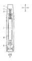
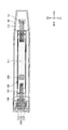
次に、第1の実施の形態におけるドアハンドルについて、図7から図9に基づき説明する。本実施の形態におけるドアハンドルは、外観は図1から図3に示されるドアハンドルと同じであり、自動車等の車両のドアの外側に取り付けられている。尚、図7は本実施の形態におけるドアハンドルにおいて、第1のドアハンドルケース11を取り除いた状態の正面図であり、図8は斜視図であり、図9は側面図である。
次に、第1の実施の形態におけるドアハンドルについて、図7から図9に基づき説明する。本実施の形態におけるドアハンドルは、外観は図1から図3に示されるドアハンドルと同じであり、自動車等の車両のドアの外側に取り付けられている。尚、図7は本実施の形態におけるドアハンドルにおいて、第1のドアハンドルケース11を取り除いた状態の正面図であり、図8は斜視図であり、図9は側面図である。
本実施の形態におけるドアハンドルは、ドアハンドルケースの中に設置されている接続電極123及び配線電極124のZ1方向の側、即ち、手の指等が近づく側に、補助電極130が設けられている。尚、補助電極130は、配線電極131により、基板111に接続されている。従って、補助電極130は、接続電極123及び配線電極124の一部のZ1側の面を覆っているが、上側ロック検出電極121及び下側ロック検出電極122は覆ってはいない。また、ロック検出電極120の接続電極123及び配線電極124のZ1側の面を覆う補助電極130を設け、補助電極130に接地電位や一定のバイアス電位を印加することにより、ある程度の誤検出を防ぐことは可能ではあるが、誤検出を排除することは十分ではない。
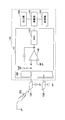
また、基板111には制御部140が設けられており、図10に示されるように、制御部140は、静電容量測定部141、演算部142、記憶部143、出力部144等を有している。静電容量測定部141は、スイッチ145、アンプ146、ADC(Analog-to-digital converter:ADコンバータ)147等を有している。スイッチ145は、ロック検出電極120及び補助電極130と接続されており、スイッチ145を閉じることにより、ロック検出電極120及び補助電極130に所定の電圧Vddを印加し、ロック検出電極120、補助電極130の各々における電位を検出することができる。検出された電位はアンプ146により増幅され、ADC147によりアナログ信号をデジタル信号に変換される。このように変換されたデジタル信号に基づき、手の指200等とロック検出電極120における静電容量の値、手の指200等と補助電極130における静電容量の値を得ることができ、これらの静電容量の値に基づき演算部142において演算や比較等がなされ、出力部144よりロック信号が出力される。本願においては、手の指200等は操作体と記載する場合がある。
本実施の形態においては、ドアハンドル10の中間領域10Cの近くに手の指等が近づいた場合には、ロック検出電極120の接続電極123や配線電極124よりも、補助電極130が手の指等に近くなるため、ロック検出電極120における静電容量の変化よりも、補助電極130における静電容量の変化が顕著となる。よって、ロック検出電極120における静電容量と、補助電極130における静電容量とを測定し、手の指200等による操作が、ドアをロックするための操作であるか否かを判断することができる。
本実施の形態においては、ロック検出電極120は、上側ロック検出電極121または下側ロック検出電極122のいずれか一方のみであってもよく、補助電極130は、ロック検出電極120の上側ロック検出電極121の検出領域6Aの周囲や、下側ロック検出電極122の検出領域6Bの周囲に設置されていてもよいが、図7及び図8に示されるように、上側ロック検出電極121及び下側ロック検出電極122の双方が設けられている構成のものの方が、製造上の観点等から好ましい。
(ドアハンドルのロック)
次に、本実施の形態におけるドアハンドルのロック操作について、図11に基づき説明する。尚、下記のロック操作の制御は、制御部140において行われる。
次に、本実施の形態におけるドアハンドルのロック操作について、図11に基づき説明する。尚、下記のロック操作の制御は、制御部140において行われる。
最初に、ステップ102(S102)に示すように、静電容量測定部141において、ロック検出電極120に所定の電圧を印加し、ロック検出電極120における電圧を測定することにより、ロック検出電極120と手の指200等との静電容量の測定を行う。ロック検出電極120における電圧を測定する際には、補助電極130に、接地電位または所定のバイアス電位等を印加してもよい。本願においては、この際測定されるロック検出電極120と手の指200等との静電容量を第1の静電容量と記載する場合がある。
次に、ステップ104(S104)に示すように、静電容量測定部141において、補助電極130に所定の電圧を印加し、補助電極130における電圧を測定することにより、補助電極130と手の指200等との静電容量の測定を行う。本願においては、この際測定される補助電極130と手の指200等との静電容量を第2の静電容量と記載する場合がある。
次に、ステップ106(S106)に示すように、第1の静電容量、即ち、ロック検出電極120と手の指200等との静電容量が、所定の第1の基準容量以上であるか否かが判断される。この判断は演算部142等により行われる。第1の基準容量の値は、ロック検出電極120に手の指200等が近づいた際に、ロック操作がなされたことの判断の基準となる値であり、予め、制御部140内の記憶部143等に記憶されている。第1の静電容量が第1の基準容量以上である場合にはステップ108に移行し、第1の静電容量が第1の基準容量未満である場合にはステップ102に移行し、再び静電容量の測定を行う。
次に、ステップ108(S108)に示すように、第2の静電容量、即ち、補助電極130と手の指200等との静電容量が、所定の第2の基準容量以上であるか否かが判断される。第2の基準容量の値は、補助電極130に手の指200等が近づいた際に、誤検出であることの判断の基準となる値であり、予め、制御部140内の記憶部143等に記憶されている。第2の静電容量が第2の基準容量以上である場合にはステップ102に移行し、再び静電容量の測定を行う。第2の静電容量が第2の基準容量未満である場合にはステップ110に移行する。
次に、ステップ110(S110)に示すように、ドアをロックするためのロック信号が出力部144より出力される。これにより、ドアがロックされる。
尚、本実施の形態においては、ステップ102とステップ104の順序は逆であってもよく、また、ステップ106とステップ108の順序は逆であってもよい。
以上のように、図3から図5に示される構造のドアハンドルでは、ロック検出電極120の接続電極123等に手の指200等が近づき、ロック検出電極120において検出される第1の静電容量が、第1の基準容量以上である場合には、ロック信号が出力される。本実施の形態においては、補助電極130が設けられており、補助電極130において検出される第2の静電容量が、第2の基準容量以上となった場合には、この手の指200等による操作は、ドアのロックをすることを意図した操作ではないものと判断され、ロック信号は出力されない。これにより、手の指等の操作の誤検出を防ぎ、ドアのロックを意図した操作のみロック操作であることを検出することが可能となる。
〔第2の実施の形態〕
次に、第2の実施の形態におけるドアハンドルのロック操作について、図12に基づき説明する。尚、下記のロック操作の制御は、制御部140において行われる。
次に、第2の実施の形態におけるドアハンドルのロック操作について、図12に基づき説明する。尚、下記のロック操作の制御は、制御部140において行われる。
最初に、ステップ202(S202)に示すように、静電容量測定部141において、ロック検出電極120に所定の電圧を印加し、ロック検出電極120における電圧を測定することにより、ロック検出電極120と手の指200等との静電容量、即ち、第1の静電容量の測定を行う。
次に、ステップ204(S204)に示すように、静電容量測定部141において、補助電極130に所定の電圧を印加し、補助電極130における電圧を測定することにより、補助電極130と手の指200等との静電容量、即ち、第2の静電容量の測定を行う。
次に、ステップ206(S206)に示すように、第1の静電容量と第2の静電容量との静電容量差を算出する。具体的には、演算部142等により、静電容量差を、静電容量差=第1の静電容量-第2の静電容量より算出する。
次に、ステップ208(S208)に示すように、静電容量差が所定の容量差以上であるか否かが判断される。この所定の容量差は、ロック操作の判断の基準となる値であり、予め、制御部140内の記憶部143等に記憶されている。この判断は演算部142等により行われる。静電容量差が所定の容量差以上である場合には、手の指200等は、補助電極130よりも、ロック検出電極120の上側ロック検出電極121や下側ロック検出電極122の近くにあるものと考えられ、手の指等による操作は、ドアをロックすることを意図した操作であるものと判断され、ステップ210に移行する。静電容量差が所定の容量差未満である場合には、手の指200等は、ロック検出電極120の上側ロック検出電極121や下側ロック検出電極122よりも、補助電極130の近くにあるものと考えられ、手の指等による操作は、ドアをロックすることを意図した操作ではなく、誤検出と判断され、ロック信号は出力されず、ステップ202に移行し、再び静電容量の測定を行う。
次に、ステップ210(S210)に示すように、ドアをロックするためのロック信号が出力部144より出力される。これにより、ドアがロックされる。
尚、上記以外の内容については、第1の実施の形態と同様である。
以上、実施の形態について詳述したが、特定の実施形態に限定されるものではなく、請求の範囲に記載された範囲内において、種々の変形及び変更が可能である。
尚、本国際出願は、2018年3月23日に出願した日本国特許出願第2018-056213号に基づく優先権を主張するものであり、その出願の全内容は本国際出願に援用する。
10 ドアハンドル
11 第1のドアハンドルケース
12 第2のドアハンドルケース
12a 表面
100 静電センサ
111 基板
113 配線
120 ロック検出電極
121 上側ロック検出電極
122 下側ロック検出電極
123 接続電極
124 配線電極
130 補助電極
131 配線電極
140 制御部
141 静電容量測定部
142 演算部
143 記憶部
144 出力部
145 スイッチ
146 アンプ
147 ADC
200 手の指
11 第1のドアハンドルケース
12 第2のドアハンドルケース
12a 表面
100 静電センサ
111 基板
113 配線
120 ロック検出電極
121 上側ロック検出電極
122 下側ロック検出電極
123 接続電極
124 配線電極
130 補助電極
131 配線電極
140 制御部
141 静電容量測定部
142 演算部
143 記憶部
144 出力部
145 スイッチ
146 アンプ
147 ADC
200 手の指
Claims (8)
- ドアハンドルケースと、
前記ドアハンドルケースの中に設置された検出電極と、
前記ドアハンドルケースの中において、前記検出電極の近傍、または、前記検出電極の一部を覆うように設置された補助電極と、
前記検出電極及び前記補助電極に接続された制御部と、
を有し、
前記検出電極及び前記補助電極は、操作体との静電容量を測定するものであって、
前記制御部は、前記検出電極において検出された第1の静電容量と、前記補助電極において検出された第2の静電容量と、に基づき、前記操作体による操作を判断することを特徴とするドアハンドル。 - 前記制御部は、
前記第1の静電容量が第1の基準容量以上であって、前記第2の静電容量が第2の基準容量未満である場合には、前記操作体による操作がなされたものと判断することを特徴とする請求項1に記載のドアハンドル。 - 前記制御部は、
前記第2の静電容量が第2の基準容量以上である場合には、前記操作体による操作がなされなかったものと判断することを特徴とする請求項1または2に記載のドアハンドル。 - 前記制御部は、
前記第1の静電容量と前記第2の静電容量との静電容量差が、所定の容量差以上である場合には、前記操作体による操作がなされたものと判断することを特徴とする請求項1に記載のドアハンドル。 - 前記制御部は、前記検出電極において第1の静電容量を検出する際には、前記補助電極には、接地電位、または、所定の電位が印加されていることを特徴とする請求項1または2に記載のドアハンドル。
- 前記検出電極は、第1の検出電極と、第2の検出電極と、前記第1の検出電極と前記第2の検出電極とを接続する接続電極により形成されており、
前記補助電極は、前記接続電極の一部を覆っていることを特徴とする請求項1から5のいずれかに記載のドアハンドル。 - 前記ドアハンドルは車両のドアに取り付けられており、
前記検出電極は、ロック検出電極であって、
前記操作体による操作は、前記ドアをロックするための操作であることを特徴とする請求項1から6のいずれかに記載のドアハンドル。 - ドアハンドルケースと、
前記ドアハンドルケースの中に入れられている検出電極と、
前記ドアハンドルケースの中において、前記検出電極の近傍、または、前記検出電極の一部を覆うように設けられた補助電極と、
前記検出電極及び前記補助電極に接続された制御部と、
を有し、
前記検出電極及び前記補助電極は、操作体との静電容量を測定するものであって、
前記検出電極は、第1の検出電極と、第2の検出電極と、前記第1の検出電極と前記第2の検出電極とを接続する接続電極により形成されており、
前記補助電極は、前記接続電極の一部を覆っていることを特徴とするドアハンドル。
Applications Claiming Priority (2)
| Application Number | Priority Date | Filing Date | Title |
|---|---|---|---|
| JP2018-056213 | 2018-03-23 | ||
| JP2018056213A JP2021080626A (ja) | 2018-03-23 | 2018-03-23 | ドアハンドル |
Publications (1)
| Publication Number | Publication Date |
|---|---|
| WO2019181237A1 true WO2019181237A1 (ja) | 2019-09-26 |
Family
ID=67987714
Family Applications (1)
| Application Number | Title | Priority Date | Filing Date |
|---|---|---|---|
| PCT/JP2019/003710 Ceased WO2019181237A1 (ja) | 2018-03-23 | 2019-02-01 | ドアハンドル |
Country Status (2)
| Country | Link |
|---|---|
| JP (1) | JP2021080626A (ja) |
| WO (1) | WO2019181237A1 (ja) |
Citations (5)
| Publication number | Priority date | Publication date | Assignee | Title |
|---|---|---|---|---|
| JP2008108534A (ja) * | 2006-10-25 | 2008-05-08 | Fujikura Ltd | 人体接近検出装置 |
| JP2009030360A (ja) * | 2007-07-27 | 2009-02-12 | Aisin Seiki Co Ltd | ドアハンドル装置 |
| JP2010024797A (ja) * | 2008-07-24 | 2010-02-04 | Aisin Seiki Co Ltd | ドアハンドル装置 |
| JP2010239587A (ja) * | 2009-03-31 | 2010-10-21 | Fujikura Ltd | 車両用ドア開閉装置 |
| JP2013113626A (ja) * | 2011-11-25 | 2013-06-10 | Aisin Seiki Co Ltd | 操作入力検知装置及び開閉部材制御装置 |
-
2018
- 2018-03-23 JP JP2018056213A patent/JP2021080626A/ja active Pending
-
2019
- 2019-02-01 WO PCT/JP2019/003710 patent/WO2019181237A1/ja not_active Ceased
Patent Citations (5)
| Publication number | Priority date | Publication date | Assignee | Title |
|---|---|---|---|---|
| JP2008108534A (ja) * | 2006-10-25 | 2008-05-08 | Fujikura Ltd | 人体接近検出装置 |
| JP2009030360A (ja) * | 2007-07-27 | 2009-02-12 | Aisin Seiki Co Ltd | ドアハンドル装置 |
| JP2010024797A (ja) * | 2008-07-24 | 2010-02-04 | Aisin Seiki Co Ltd | ドアハンドル装置 |
| JP2010239587A (ja) * | 2009-03-31 | 2010-10-21 | Fujikura Ltd | 車両用ドア開閉装置 |
| JP2013113626A (ja) * | 2011-11-25 | 2013-06-10 | Aisin Seiki Co Ltd | 操作入力検知装置及び開閉部材制御装置 |
Also Published As
| Publication number | Publication date |
|---|---|
| JP2021080626A (ja) | 2021-05-27 |
Similar Documents
| Publication | Publication Date | Title |
|---|---|---|
| JP5605205B2 (ja) | 静電容量検出装置および接触検知センサ | |
| JP6121397B2 (ja) | 携帯デバイスへの接近の検出のための測定デバイスおよび方法 | |
| JP6860742B2 (ja) | ドアハンドル | |
| JP5405874B2 (ja) | 静電容量式入力装置および車載機器制御装置 | |
| JP7203235B2 (ja) | ドアハンドルおよび制御装置 | |
| JP2010239587A (ja) | 車両用ドア開閉装置 | |
| US11150769B2 (en) | Method for capacitively detecting contact and actuation | |
| JP6876815B2 (ja) | 操作入力装置及びドアハンドル | |
| JP6379708B2 (ja) | タッチスイッチ | |
| KR102509067B1 (ko) | 사용자 인증장치, 그것의 입력 센싱 모듈 및 사용자 인증방법 | |
| JP2021080626A (ja) | ドアハンドル | |
| US20220075464A1 (en) | Case for electronic device | |
| KR102544697B1 (ko) | 힘 검출 센서 | |
| US11946294B2 (en) | Door handle | |
| JP6212824B2 (ja) | アウトドアハンドル装置 | |
| JP6936385B2 (ja) | 操作検知装置及びドアハンドル | |
| KR20250021848A (ko) | 차량 도어핸들시스템 및 그의 제어방법 | |
| US11850925B2 (en) | Control apparatus of door for vehicle | |
| JP2020100983A (ja) | ドアハンドル | |
| WO2019171848A1 (ja) | 操作検知装置及びドアハンドル |
Legal Events
| Date | Code | Title | Description |
|---|---|---|---|
| 121 | Ep: the epo has been informed by wipo that ep was designated in this application |
Ref document number: 19771695 Country of ref document: EP Kind code of ref document: A1 |
|
| NENP | Non-entry into the national phase |
Ref country code: DE |
|
| 122 | Ep: pct application non-entry in european phase |
Ref document number: 19771695 Country of ref document: EP Kind code of ref document: A1 |
|
| NENP | Non-entry into the national phase |
Ref country code: JP |