WO2019176145A1 - 位置検出装置、位置検出方法、及びコンピュータ読み取り可能な記録媒体 - Google Patents
位置検出装置、位置検出方法、及びコンピュータ読み取り可能な記録媒体 Download PDFInfo
- Publication number
- WO2019176145A1 WO2019176145A1 PCT/JP2018/034491 JP2018034491W WO2019176145A1 WO 2019176145 A1 WO2019176145 A1 WO 2019176145A1 JP 2018034491 W JP2018034491 W JP 2018034491W WO 2019176145 A1 WO2019176145 A1 WO 2019176145A1
- Authority
- WO
- WIPO (PCT)
- Prior art keywords
- emitting element
- light emitting
- light
- axis
- signal
- Prior art date
- Legal status (The legal status is an assumption and is not a legal conclusion. Google has not performed a legal analysis and makes no representation as to the accuracy of the status listed.)
- Ceased
Links
Images

Classifications
-
- G—PHYSICS
- G01—MEASURING; TESTING
- G01B—MEASURING LENGTH, THICKNESS OR SIMILAR LINEAR DIMENSIONS; MEASURING ANGLES; MEASURING AREAS; MEASURING IRREGULARITIES OF SURFACES OR CONTOURS
- G01B11/00—Measuring arrangements characterised by the use of optical techniques
-
- G—PHYSICS
- G06—COMPUTING OR CALCULATING; COUNTING
- G06F—ELECTRIC DIGITAL DATA PROCESSING
- G06F3/00—Input arrangements for transferring data to be processed into a form capable of being handled by the computer; Output arrangements for transferring data from processing unit to output unit, e.g. interface arrangements
- G06F3/01—Input arrangements or combined input and output arrangements for interaction between user and computer
- G06F3/03—Arrangements for converting the position or the displacement of a member into a coded form
- G06F3/033—Pointing devices displaced or positioned by the user, e.g. mice, trackballs, pens or joysticks; Accessories therefor
- G06F3/0346—Pointing devices displaced or positioned by the user, e.g. mice, trackballs, pens or joysticks; Accessories therefor with detection of the device orientation or free movement in a three-dimensional [3D] space, e.g. 3D mice, 6-DOF [six degrees of freedom] pointers using gyroscopes, accelerometers or tilt-sensors
-
- G—PHYSICS
- G06—COMPUTING OR CALCULATING; COUNTING
- G06F—ELECTRIC DIGITAL DATA PROCESSING
- G06F3/00—Input arrangements for transferring data to be processed into a form capable of being handled by the computer; Output arrangements for transferring data from processing unit to output unit, e.g. interface arrangements
- G06F3/01—Input arrangements or combined input and output arrangements for interaction between user and computer
- G06F3/03—Arrangements for converting the position or the displacement of a member into a coded form
- G06F3/041—Digitisers, e.g. for touch screens or touch pads, characterised by the transducing means
- G06F3/042—Digitisers, e.g. for touch screens or touch pads, characterised by the transducing means by opto-electronic means
Definitions
- the present invention relates to a position detection device and a position detection method for detecting the position of an object, and further relates to a computer-readable recording medium on which a program for realizing these is recorded.
- an optical position detection device that detects the position of an object using a light emitting diode and a photodiode has been proposed (see, for example, Patent Document 1).
- the light emitted from the light emitting diode is reflected by the object and then received by the photodiode. Since the photodiode outputs a signal with an output value corresponding to the intensity of received light, the position of the object is detected by analyzing the output signal.
- Patent Document 1 discloses an optical position detection device provided on a display screen of a portable terminal device.
- the position detection device disclosed in Patent Document 1 includes first and second light emitting elements and first and second light receiving elements, which are provided in a transparent housing.
- the light emitting elements emit light alternately, and the phases of the light emitted from the light emitting elements are different from each other. Further, when the light emitted from each light emitting element is reflected by an object on the display screen, it is received by each light receiving element.
- the control unit of the position detection device receives the signal output by the first light receiving element after receiving the light emission of the first light emitting element, and the first light receiving element receives the light emission of the second light emitting element. Get the output signal.
- the control unit also obtains a signal output by the second light receiving element after receiving light emitted from the first light emitting element, and a signal output by the second light receiving element after receiving light emitted from the second light emitting element. To do.
- a control part detects the two-dimensional coordinate of an object based on these four types of signals.
- the position detection device disclosed in Patent Document 1 can detect only the position of an object on the display screen, that is, the two-dimensional coordinates of the object, and cannot be used for position detection of the object in a three-dimensional space. is there.
- depth sensors represented by TOF (Time Of Flight) sensors have been developed.
- TOF Time Of Flight
- the position of the object in the three-dimensional space can be detected only by the signal output from the depth sensor.
- the cost of the depth sensor is very high, which increases the manufacturing cost of the position detection device.
- An example of an object of the present invention is to solve the above-described problem and suppress an increase in manufacturing cost while detecting a position of an object in a three-dimensional space, a position detection apparatus, a position detection method, and a computer-readable recording medium Is to provide.
- a position detection apparatus is an apparatus for detecting the position of an object in a three-dimensional space, A first light emitting element, a second light emitting element, a third light emitting element, a light receiving element, and a control device; The first light emitting element, the second light emitting element, and the third light emitting element are disposed on the same reference plane, The light receiving element is configured so that light emitted from each of the first light emitting element, the second light emitting element, and the third light emitting element is reflected by the object and then enters the light receiving element.
- the control device includes: A lighting controller that alternately turns on the first light emitting element, the second light emitting element, and the third light emitting element; From the first signal output by the light receiving element when the first light emitting element is turned on and the second signal output by the light receiving element when the second light emitting element is turned on, the first light emitting element and Calculating a first position of the object on a first axis parallel to a line connecting the second light emitting element; A second line parallel to a line connecting the second light emitting element and the third light emitting element is obtained from the second signal and the third signal output from the light receiving element when the third light emitting element is turned on.
- Calculating a second position of the object on two axes Further, the height of the object on the first axis or the second axis is calculated, And a calculation processing unit that calculates a position of the object in a three-dimensional space based on the first position, the second position, and the height. It is characterized by that.
- a position detection method includes a first light emitting element, a second light emitting element, a third light emitting element, and a light receiving element.
- a method for detecting a position in a three-dimensional space The first light-emitting element, the second light-emitting element, and the third light-emitting element are disposed on the same reference plane, and the light-receiving element is the first light-emitting element and the second light-emitting element.
- the light emitted from each of the light emitting element and the third light emitting element is reflected in the object and then executed so as to be incident on the light receiving element.
- a computer-readable recording medium according to one aspect of the present invention.
- the first light emitting element, the second light emitting element, and the third light emitting element are disposed on the same reference plane,
- the light receiving element is configured so that light emitted from each of the first light emitting element, the second light emitting element, and the third light emitting element is reflected by the object and then enters the light receiving element.
- a computer-readable recording medium in which a program in the position detecting device is recorded In the computer, (A) alternately lighting each of the first light emitting element, the second light emitting element, and the third light emitting element; (B) From the first signal output by the light receiving element when the first light emitting element is turned on and the second signal output by the light receiving element when the second light emitting element is turned on, Calculating a first position of the object on a first axis parallel to a line connecting the light emitting element and the second light emitting element; (C) A line connecting the second light emitting element and the third light emitting element from the second signal and the third signal output by the light receiving element when the third light emitting element is turned on.
- FIG. 1 is a configuration diagram showing a configuration of a position detection device according to an embodiment of the present invention.
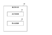
- FIG. 2 is a block diagram illustrating a configuration of a control device provided in the position detection device according to the embodiment of the present invention.
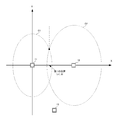
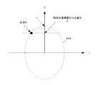
- FIG. 3 is an explanatory diagram illustrating processing when the first position of the object is calculated by the control device.
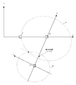
- FIG. 4 is an explanatory diagram illustrating processing when the second position of the object is calculated by the control device.
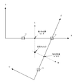
- FIG. 5 is an explanatory diagram for explaining processing when the intersection of the third axis and the fourth axis is obtained by the control device.
- FIG. 6 is an explanatory diagram for explaining processing when the height of the object from the reference plane in the three-dimensional space is calculated by the control device.
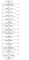
- FIG. 7 is a flowchart showing the operation of the position detection apparatus according to the embodiment of the present invention.
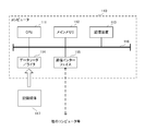
- FIG. 8 is a block diagram illustrating an example of a computer that implements a control device used in the position detection device according to the embodiment
- FIG. 1 is a configuration diagram showing a configuration of a position detection device according to an embodiment of the present invention.
- FIG. 2 is a block diagram illustrating a configuration of a control device provided in the position detection device according to the embodiment of the present invention.
- the position detection device 10 includes a first light emitting element 11, a second light emitting element 12, a third light emitting element 13, a light receiving element 14, and a control device 20. .
- the first light emitting element 11, the second light emitting element 12, and the third light emitting element 13 are disposed on the same reference plane.
- the light receiving element 14 is incident on the light receiving element 14 after the light emitted from the first light emitting element 11, the second light emitting element 12, and the third light emitting element 13 is reflected by the object 30. To be arranged.
- the control device 20 includes a lighting control unit 21 and a calculation processing unit 22.
- the lighting control unit 21 turns on the first light emitting element 11, the second light emitting element 12, and the third light emitting element 13 alternately.
- the calculation processing unit 22 outputs a first signal output from the light receiving element 14 when the first light emitting element 11 is turned on, a second signal output from the light receiving element 14 when the second light emitting element 12 is turned on, The third signal output from the light receiving element 14 when the third light emitting element 13 is turned on is acquired.
- the calculation processing unit 22 determines, based on the first signal and the second signal, the object 30 on the first axis parallel to the line connecting the first light emitting element 11 and the second light emitting element 12. A first position and a first height from the reference plane of the object 30 are calculated.
- calculation processing unit 22 uses the second signal and the third signal from the second signal and the third signal on the second axis parallel to the line connecting the second light emitting element 12 and the third light emitting element 13. 2 and the second height from the reference plane of the object 30 are calculated.
- the calculation processing unit 22 determines the position of the object 30 in the three-dimensional space based on the first position, the second position, and at least one of the first height and the second height. Is calculated.
- the position of the object 30 in the three-dimensional space can be detected by using the three light emitting elements 11 to 13 and the light receiving element 14 without using a depth sensor. That is, according to the present embodiment, it is possible to detect the position of the object 30 in the three-dimensional space while suppressing an increase in manufacturing cost.
- the configuration of the position detection apparatus 10 in the present embodiment will be set up in more detail with reference to FIG.
- the first light-emitting element 11, the second light-emitting element 12, the third light-emitting element 13, and the light-receiving element 14 are arranged on a substrate 15 provided with wiring. Is arranged. Therefore, the mounting surface of the substrate 15 becomes the reference surface described above.
- the first light emitting element 11, the second light emitting element 12, the third light emitting element 13, and the light receiving element 14 are electrically connected to the control device 20 via wiring provided on the substrate 15. Yes.
- An axis (first axis) parallel to a line connecting the first light emitting element 11 and the second light emitting element 12 is defined as an X axis, and an axis perpendicular to the X axis and parallel to the reference plane is defined.
- the Y axis is assumed.
- an axis parallel to the normal direction of the reference plane is taken as a Z axis. Note that, as shown in FIGS. 3 to 6 to be described later, in this embodiment, the X axis passes through the center of the first light emitting element and the center of the second light emitting element.
- the Y axis passes through the center of the first light emitting element.
- the first light emitting element 11, the second light emitting element 12, and the third light emitting element 13 are LEDs (Light Emitting Diode).
- the light receiving element 14 is a PD (Phot Diode) and outputs a signal corresponding to the amount of received light.
- the control device 20 is constructed by installing a program to be described later in a computer and executing the program.
- FIG. 3 is an explanatory diagram illustrating processing when the first position of the object is calculated by the control device.
- FIG. 4 is an explanatory diagram illustrating processing when the second position of the object is calculated by the control device.
- FIG. 5 is an explanatory diagram for explaining processing when the intersection of the third axis and the fourth axis is obtained by the control device.
- FIG. 6 is an explanatory diagram illustrating processing when the height of the object from the reference plane in the three-dimensional space is calculated by the control device.
- the lighting control unit 21 turns on the first light emitting element 11, the second light emitting element 12, and the third light emitting element 13 alternately at regular intervals.
- the light receiving element 14 outputs the first signal, the second signal, and the third signal corresponding to the light amount of the received light at regular intervals.
- the calculation process part 22 acquires the 1st signal, the 2nd signal, and the 3rd signal which the light receiving element 14 output, and specifies a light quantity for every acquired signal.
- the calculation processing unit 22 determines the light amount specified from the first signal, the light emission characteristics of the first light emitting element 11, the light amount specified from the second signal, and the second light emitting element.
- the ellipse O1 corresponding to the first light emitting element 11 and the O2 corresponding to the second light emitting element 12 are drawn using the light emission characteristics of 12.
- the calculation processing unit 22 includes an ellipse O1 indicating the amount of light of the first light emitting element 11 on the virtual plane (XY plane) including the X axis and parallel to the reference plane, and the second light emitting element 12.
- An ellipse O2 indicating the amount of light is drawn.
- the calculation processing unit 22 draws an ellipse O1 using the following formula 1, and draws an ellipse O2 using the following formula 2.
- a and b indicate parameters specified by the characteristics of the first light emitting element 11.
- c represents the distance between the first light emitting element 11 and the second light emitting element 12, and d and e represent parameters specified by the characteristics of the second light emitting element 12. .
- the calculation processing unit 22 calculates the first position (x1, 0) on the X axis from the position of the intersection of the ellipse O1 and the ellipse O2.
- the light emitting element since the light amount of the light emitting element has directivity, the light emitting element has a light emission characteristic that the light amount on the front surface is large and decreases toward the periphery.
- the parameters specified by the characteristics of the light-emitting element described above define such characteristics. Specifically, in the above formulas 1 and 2, each parameter is determined such that the long axis of the ellipse indicates the amount of light at the front and the short axis of the ellipse indicates the amount of light at the periphery.
- the calculation processing unit 22 determines the light amount specified from the second signal, the light emission characteristics of the second light emitting element 12, the light amount specified from the third signal, and the third light emitting element. Using eleven emission characteristics, an ellipse V1 corresponding to the second light emitting element and an ellipse V2 corresponding to the third light emitting element are drawn.
- an axis (second axis) parallel to a line connecting the second light emitting element 12 and the third light emitting element 13 is defined as an X ′ axis.
- the X ′ axis passes through the center of the second light emitting element 12 and the center of the third light emitting element 13.
- an axis parallel to the XY plane and perpendicular to the X ′ axis is taken as the Y ′ axis, and the Y ′ axis passes through the center of the second light emitting element 12.
- the calculation processing unit 22 includes an ellipse V1 indicating the light amount of the second light emitting element 12 on a virtual plane (X′Y ′ plane) including the X ′ axis and parallel to the reference plane, and a third An ellipse V2 indicating the light quantity of the light emitting element 13 is drawn.
- the calculation processing unit 22 draws the ellipse V1 using the following formula 3, and draws the ellipse V1 using the following formula 4.
- d and e indicate parameters specified by the characteristics of the second light emitting element 12 as described above.
- f represents the distance between the second light emitting element 12 and the third light emitting element 13
- g and h represent parameters specified by the characteristics of the third light emitting element 13.
- the calculation processing unit 22 calculates the second position (x′2, 0) on the X ′ axis from the position of the intersection of the ellipse V1 and the ellipse V2.
- the positional relationship among the first light emitting element 11, the second light emitting element 12, and the third light emitting element 13 is determined in advance, and the relationship between the X axis and the Y axis, and the X ′ axis and the Y ′ axis. Is also predetermined. For this reason, the calculation process part 22 can convert the coordinate of a 2nd position into XY coordinate system using this relationship.
- the calculation processing unit 22 also applies the light amount of the first light emitting element 11 to the virtual plane (XZ plane) including the X axis and perpendicular to the reference plane, similarly to the case where the ellipse O1 and the ellipse O2 are drawn. It is also possible to draw an ellipse O11 shown and an ellipse O12 showing the light quantity of the second light emitting element 12.
- the calculation processing unit 22 draws an ellipse OV1 using the following formula 5, and draws an ellipse OV2 using the following formula 6.
- the calculation processing unit 22 calculates the height from the reference plane of the object 30 on the X axis from the position of the intersection of the two ellipses OV1 and OV2 drawn on the virtual plane (XZ plane) perpendicular to the reference plane. Z is calculated.
- the calculation processing unit 22 sets the L axis, which is perpendicular to the X axis and has the first position (x1, 0) as the origin, and is perpendicular to the X ′ axis. Yes, and the M axis is set with the second position (x′2, 0) as the origin.
- the L axis is represented by the following formula 7 in the XY coordinate system
- the M axis is represented by the following formula 8 in the XY coordinate system.
- ⁇ and ⁇ are coefficients determined by the positional relationship of the first light emitting element 11, the second light emitting element 12, and the third light emitting element 13.
- the calculation processing unit 22 obtains the position of the intersection A between the L axis and the M axis using the above equations 7 and 8.
- the coordinates of the intersection are (x1, y1).
- the calculation processing unit 22 has the height z calculated previously and the light emission of the first light emitting element 11 on a virtual plane (LZ plane) including the L axis and perpendicular to the reference plane.
- the ellipse 0V3 is drawn using the characteristics and the light emission characteristics of the second light emitting element 12. Specifically, the calculation processing unit 22 draws the ellipse OV3 using the following formula 7.
- the calculation processing unit 22 obtains a point that matches the intersection (x1, y1) of the L axis and the M axis on the drawn ellipse OV3, and calculates the height of the obtained point from the reference plane of the object 30.
- FIG. 7 is a flowchart showing the operation of the position detection apparatus according to the embodiment of the present invention.
- FIGS. 1 to 6 are referred to as appropriate.
- the position detection method is implemented by operating the position detection device. Therefore, the description of the position detection method in the present embodiment is replaced with the following description of the operation of the position detection device 10.
- the lighting control unit 21 temporarily turns off all the light emitting elements (step A1).
- the lighting control unit 21 turns on the first light emitting element 11 (step A2).
- step A2 When step A2 is executed, the light emitted from the first light emitting element 11 is reflected by the object 30, enters the light receiving element 14, and the light receiving element 14 outputs the first signal. 22 acquires the first signal (step A3). In addition, the calculation processing unit 22 identifies the amount of light of the first light emitting element 11 from the acquired first signal.
- the lighting control unit 21 turns off the first light emitting element 11 (step A4) and turns on the second light emitting element 12 (step A5).
- step A5 When step A5 is executed, the light emitted from the second light emitting element 12 is reflected by the object 30, enters the light receiving element 14, and the light receiving element 14 outputs the second signal. 22 acquires the second signal (step A6). In addition, the calculation processing unit 22 specifies the light amount of the second light emitting element 12 from the acquired second signal.
- step A6 the lighting control unit 21 turns off the second light emitting element 12 (step A7).
- the calculation processing unit 22 has an ellipse O1 indicating the light amount of the first light emitting element 11 and an ellipse O2 indicating the light amount of the second light emitting element 12 on the virtual plane (XY plane). And the first position (x1, 0) on the X axis is calculated from the position of the intersection of these ellipses (step A8).
- the lighting control unit 21 turns on the third light emitting element 13 (step A9).
- step A9 the light emitted from the third light emitting element 13 is reflected by the object 30 and enters the light receiving element 14, and the light receiving element 14 outputs the third signal, so that the calculation processing unit 22 acquires the third signal (step A10).
- the calculation processing unit 22 specifies the amount of light of the third light emitting element 13 from the acquired third signal.
- step A10 the lighting control unit 21 turns off the second light emitting element 12 (step A11).
- the calculation processing unit 22 sets an ellipse V ⁇ b> 1 indicating the light amount of the second light emitting element 12 and the light amount of the third light emitting element 13 on the virtual plane (X′Y ′ plane).
- the ellipse V2 shown is drawn, and the second position (x′2, 0) on the X ′ axis is calculated from the position of the intersection of these ellipses (step A12).
- the calculation processing unit 22 draws an ellipse O11 indicating the light amount of the first light emitting element 11 and an ellipse O12 indicating the light amount of the second light emitting element 12 on the virtual plane (XZ plane).
- the height z from the reference plane of the object 30 on the X axis is calculated from the position of the intersection of the ellipses (step A13).
- the calculation processing unit 22 sets the L axis, which is perpendicular to the X axis and has the first position (x1, 0) as the origin, is perpendicular to the X ′ axis, and is The M axis is set with the position (x′2, 0) as the origin. Then, the calculation processing unit 22 calculates the intersection A (x1, y1) between the L axis and the M axis (step A14).
- the calculation processing unit 22 calculates the position of the object 30 in the three-dimensional space (step A15). Specifically, as illustrated in FIG. 6, the calculation processing unit 22 includes, on a virtual plane (LZ plane), the height z calculated in Step A13, the light emission characteristics of the first light emitting element 11, and the second An ellipse 0V3 is drawn using the light emission characteristics of the light emitting element 12. Then, the calculation processing unit 22 obtains a point that matches the intersection (x1, y1) of the L axis and the M axis on the drawn ellipse OV3, and calculates the height z1 of the obtained point from the reference plane as the object 30. The position (x1, y1, z1) of the object 30 in the three-dimensional space is calculated as the height from the reference plane in the three-dimensional space.
- step A15 if the position detection device 10 is not instructed to end, step A1 is executed again.
- the position of the object 30 is detected continuously.
- the position of the object 30 in the three-dimensional space can be detected by using the three light emitting elements 11 to 13 and the light receiving element 14. Therefore, according to the present embodiment, it is possible to detect the position of the object 30 in the three-dimensional space while suppressing an increase in manufacturing cost.
- step A13 the height z in the XZ plane is obtained by using the light amount of the first light emitting element 11 and the light amount of the second light emitting element 12, but in this embodiment, the second light emission is performed.
- the height in the X′Z plane may be obtained using the light amount of the element 12 and the light amount of the third light emitting element 13.
- the calculation processing unit 22 draws an ellipse on the MZ plane and calculates the height z1 of the object.
- the program in the present embodiment may be a program that causes a computer to execute steps A1 to A15 shown in FIG.
- the computer includes a computer that functions as the control device 20, and the processor of the computer functions as the lighting control unit 21 and the calculation processing unit 22 to perform processing.
- each computer may function as any one of the lighting control unit 21 and the calculation processing unit 22.
- FIG. 8 is a block diagram illustrating an example of a computer that implements a control device used in the position detection device according to the embodiment of the present invention.
- the computer 110 includes a CPU (Central Processing Unit) 111, a main memory 112, a storage device 113, a data reader / writer 114, and a communication interface 115. These units are connected to each other via a bus 116 so that data communication is possible.
- the computer 110 may include a GPU (GraphicsGraphProcessing Unit) or an FPGA (Field-Programmable Gate Array) in addition to or instead of the CPU 111.
- the CPU 111 performs various operations by developing the program (code) in the present embodiment stored in the storage device 113 in the main memory 112 and executing them in a predetermined order.
- the main memory 112 is typically a volatile storage device such as a DRAM (Dynamic Random Access Memory).
- the program in the present embodiment is provided in a state of being stored in a computer-readable recording medium 117. Note that the program in the present embodiment may be distributed on the Internet connected via the communication interface 115.
- the storage device 113 includes a hard disk drive and a semiconductor storage device such as a flash memory.
- the data reader / writer 114 mediates data transmission between the CPU 111 and the recording medium 117, and reads a program from the recording medium 117 and writes a processing result in the computer 110 to the recording medium 117.
- the communication interface 115 mediates data transmission between the CPU 111 and another computer.
- the recording medium 117 include a general-purpose semiconductor storage device such as CF (Compact Flash (registered trademark)) and SD (Secure Digital), a magnetic recording medium such as a flexible disk (CD), or a CD- Optical recording media such as ROM (Compact Disk Read Only Memory) are listed.
- CF Compact Flash
- SD Secure Digital
- CD- Optical recording media such as ROM (Compact Disk Read Only Memory) are listed.
- control device 20 in the present embodiment can be realized by using hardware corresponding to each unit instead of the computer in which the program is installed. Furthermore, a part of the control device 20 may be realized by a program, and the remaining part may be realized by hardware.
- Appendix 1 An apparatus for detecting the position of an object in a three-dimensional space, A first light emitting element, a second light emitting element, a third light emitting element, a light receiving element, and a control device; The first light emitting element, the second light emitting element, and the third light emitting element are disposed on the same reference plane, The light receiving element is configured so that light emitted from each of the first light emitting element, the second light emitting element, and the third light emitting element is reflected by the object and then enters the light receiving element.
- the control device includes: A lighting controller that alternately turns on the first light emitting element, the second light emitting element, and the third light emitting element; From the first signal output by the light receiving element when the first light emitting element is turned on and the second signal output by the light receiving element when the second light emitting element is turned on, the first light emitting element and Calculating a first position of the object on a first axis parallel to a line connecting the second light emitting element; A second line parallel to a line connecting the second light emitting element and the third light emitting element is obtained from the second signal and the third signal output from the light receiving element when the third light emitting element is turned on.
- a position detecting device characterized by that.
- the calculation processing unit includes: Using the light quantity specified by the first signal, the light emission characteristic of the first light emitting element, the light quantity specified by the second signal, and the light emission characteristic of the second light emitting element, the first light emitting element is used.
- An ellipse that indicates the light amount of the first light emitting element and an ellipse that indicates the light amount of the second light emitting element are drawn on a virtual plane that includes an axis and is parallel to the reference plane.
- a third axis is set that is perpendicular to the first axis and that has the first position as the origin, is perpendicular to the second axis, and has the second position as the origin
- Set a fourth axis determine the position of the intersection of the third axis and the fourth axis, Then, the calculated height on the first axis and the light emission characteristics of the first light emitting element or the light emission of the second light emitting element on a virtual plane perpendicular to the reference plane including the third axis.
- a position detecting device characterized by that.
- Appendix 4 A method for detecting a position of an object in a three-dimensional space using a first light emitting element, a second light emitting element, a third light emitting element, and a light receiving element,
- the first light-emitting element, the second light-emitting element, and the third light-emitting element are disposed on the same reference plane, and the light-receiving element is the first light-emitting element and the second light-emitting element.
- the light emitted from each of the light emitting element and the third light emitting element is reflected in the object and then executed so as to be incident on the light receiving element.
- step (c) Using the light quantity specified by the second signal, the light emission characteristic of the second light emitting element, the light quantity specified by the third signal, and the light emission characteristic of the third light emitting element, An ellipse indicating the light amount of the second light emitting element and an ellipse indicating the light amount of the third light emitting element are drawn on a virtual plane parallel to the reference plane including the axis, and Calculating the second position from the position of the intersection; A position detection method characterized by the above.
- the height on the first axis is calculated,
- a third axis is set that is perpendicular to the first axis and that has the first position as the origin, is perpendicular to the second axis, and has the second position as the origin
- Set a fourth axis determine the position of the intersection of the third axis and the fourth axis. Then, the calculated height on the first axis and the light emission characteristics of the first light emitting element or the light emission of the second light emitting element on a virtual plane perpendicular to the reference plane including the third axis.
- the first light emitting element, the second light emitting element, and the third light emitting element are disposed on the same reference plane,
- the light receiving element is configured so that light emitted from each of the first light emitting element, the second light emitting element, and the third light emitting element is reflected by the object and then enters the light receiving element.
- a computer-readable recording medium in which a program in the position detecting device is recorded In the computer, (A) alternately lighting each of the first light emitting element, the second light emitting element, and the third light emitting element; (B) From the first signal output by the light receiving element when the first light emitting element is turned on and the second signal output by the light receiving element when the second light emitting element is turned on, Calculating a first position of the object on a first axis parallel to a line connecting the light emitting element and the second light emitting element; (C) A line connecting the second light emitting element and the third light emitting element from the second signal and the third signal output by the light receiving element when the third light emitting element is turned on.
- step (c) Using the light quantity specified by the second signal, the light emission characteristic of the second light emitting element, the light quantity specified by the third signal, and the light emission characteristic of the third light emitting element, An ellipse indicating the light amount of the second light emitting element and an ellipse indicating the light amount of the third light emitting element are drawn on a virtual plane parallel to the reference plane including the axis, and Calculating the second position from the position of the intersection; A computer-readable recording medium.
- the height on the first axis is calculated,
- a third axis is set that is perpendicular to the first axis and that has the first position as the origin, is perpendicular to the second axis, and has the second position as the origin
- Set a fourth axis determine the position of the intersection of the third axis and the fourth axis. Then, the calculated height on the first axis and the light emission characteristics of the first light emitting element or the light emission of the second light emitting element on a virtual plane perpendicular to the reference plane including the third axis.
- the present invention it is possible to detect the position of an object in a three-dimensional space while suppressing an increase in manufacturing cost.
- the present invention is useful in the field where detection of an object, for example, a position in a three-dimensional space of a hand is required.
Landscapes
- Physics & Mathematics (AREA)
- General Physics & Mathematics (AREA)
- Length Measuring Devices By Optical Means (AREA)
- Position Input By Displaying (AREA)
Abstract
位置検出装置は、発光素子11、発光素子12、発光素子13、受光素子14、制御装置20を備える。制御装置20は、発光素子を交互に点灯させ、発光素子11の点灯時に受光素子14が出力した第1の信号と、第2の発光素子12の点灯時に受光素子14が出力した第2の信号とから、発光素子11と発光素子12とを結ぶ線に平行な軸上の物体30の第1の位置を算出し、第2の信号と、発光素子13の点灯時に受光素子14が出力した第3の信号とから、発光素子12と発光素子13とを結ぶ線に平行な軸上の物体30の第2の位置を算出し、いずれかの軸上での物体30の高さを算出し、第1及び第2の位置と、軸上の高さとに基づいて、物体30の3次元空間上の位置を算出する。
Description
本発明は、物体の位置を検出するための、位置検出装置、及び位置検出方法に関し、更には、これらを実現するためのプログラムを記録したコンピュータ読み取り可能な記録媒体に関する。
近年、発光ダイオードとフォトダイオードとを用いて物体の位置を検出する、光学式の位置検出装置が提案されている(例えば、特許文献1参照)。このような装置では、発光ダイオードから出射された光は、物体で反射された後に、フォトダイオードによって受光される。フォトダイオードは、受光した光の強度に応じた出力値で信号を出力するので、出力された信号を分析することで、物体の位置が検出される。
具体的には、特許文献1は、携帯型端末装置の表示画面上に設けられる光学式の位置検出装置を開示している。特許文献1に開示された位置検出装置は、第1及び第2の発光素子と、第1及び第2の受光素子とを備え、これらは透明なハウジング内に備えられている。
更に、特許文献1に開示された位置検出装置では、各発光素子は、交互に光を出射すると共に、各発光素子から出射される光の位相は互いに異なっている。また、各発光素子から出射された光は、表示画面上の物体で反射されると、各受光素子で受光される。
そして、この位置検出装置の制御部は、第1の受光素子が、第1の発光素子の発光を受けて出力した信号と、第1の受光素子が、第2の発光素子の発光を受けて出力した信号とを取得する。また、制御部は、第2の受光素子が、第1の発光素子の発光を受けて出力した信号と、第2の受光素子が、第2の発光素子の発光を受けて出力した信号も取得する。そして、制御部は、これらの4種類の信号に基づいて、物体の2次元座標を検出する。
しかしながら、特許文献1に開示された位置検出装置では、物体の表示画面上での位置、即ち、物体の2次元座標しか検出できず、3次元空間での物体の位置検出に利用できないという問題がある。
一方、近年においては、TOF(Time Of Flight)センサに代表されるデプスセンサが開発されている。デプスセンサによれば、それが出力する信号のみで、物体の3次元空間における位置を検出することができる。但し、デプスセンサのコストは非常に高く、位置検出装置の製造コストを押し上げてしまう。
本発明の目的の一例は、上記問題を解消し、製造コストの増加を抑制しつつ、物体の3次元空間における位置を検出し得る、位置検出装置、位置検出方法、及びコンピュータ読み取り可能な記録媒体を提供することにある。
上記目的を達成するため、本発明の一側面における位置検出装置は、物体の3次元空間上の位置を検出するための装置であって、
第1の発光素子と、第2の発光素子と、第3の発光素子と、受光素子と、制御装置とを備え、
前記第1の発光素子、前記第2の発光素子、前記第3の発光素子は、同一の基準面上に配置され、
前記受光素子は、前記第1の発光素子、前記第2の発光素子、及び前記第3の発光素子、それぞれから出射された光が、前記物体に反射された後に、当該受光素子に入射するように、配置され、
前記制御装置は、
前記第1の発光素子、前記第2の発光素子、及び前記第3の発光素子をそれぞれ交互に点灯させる、点灯制御部と、
前記第1の発光素子の点灯時に前記受光素子が出力した第1の信号と、前記第2の発光素子の点灯時に前記受光素子が出力した第2の信号とから、前記第1の発光素子と前記第2の発光素子とを結ぶ線に平行な第1の軸上における、前記物体の第1の位置を算出し、
前記第2の信号と、前記第3の発光素子の点灯時に前記受光素子が出力した第3の信号とから、前記第2の発光素子と前記第3の発光素子とを結ぶ線に平行な第2の軸上における、前記物体の第2の位置を算出し、
更に、前記第1の軸上又は前記第2の軸上における前記物体の高さを算出し、
そして、前記第1の位置と、前記第2の位置と、前記高さとに基づいて、前記物体の3次元空間上の位置を算出する、算出処理部と、を備えている、
ことを特徴とする。
第1の発光素子と、第2の発光素子と、第3の発光素子と、受光素子と、制御装置とを備え、
前記第1の発光素子、前記第2の発光素子、前記第3の発光素子は、同一の基準面上に配置され、
前記受光素子は、前記第1の発光素子、前記第2の発光素子、及び前記第3の発光素子、それぞれから出射された光が、前記物体に反射された後に、当該受光素子に入射するように、配置され、
前記制御装置は、
前記第1の発光素子、前記第2の発光素子、及び前記第3の発光素子をそれぞれ交互に点灯させる、点灯制御部と、
前記第1の発光素子の点灯時に前記受光素子が出力した第1の信号と、前記第2の発光素子の点灯時に前記受光素子が出力した第2の信号とから、前記第1の発光素子と前記第2の発光素子とを結ぶ線に平行な第1の軸上における、前記物体の第1の位置を算出し、
前記第2の信号と、前記第3の発光素子の点灯時に前記受光素子が出力した第3の信号とから、前記第2の発光素子と前記第3の発光素子とを結ぶ線に平行な第2の軸上における、前記物体の第2の位置を算出し、
更に、前記第1の軸上又は前記第2の軸上における前記物体の高さを算出し、
そして、前記第1の位置と、前記第2の位置と、前記高さとに基づいて、前記物体の3次元空間上の位置を算出する、算出処理部と、を備えている、
ことを特徴とする。
また、上記目的を達成するため、本発明の一側面における位置検出方法は、第1の発光素子と、第2の発光素子と、第3の発光素子と、受光素子とを用いて、物体の3次元空間上の位置を検出するための方法であって、
前記第1の発光素子、前記第2の発光素子、及び前記第3の発光素子を、同一の基準面上に配置し、更に、前記受光素子を、前記第1の発光素子、前記第2の発光素子、及び前記第3の発光素子、それぞれから出射された光が、前記物体に反射された後に、当該受光素子に入射するように、配置した状態で実行され、
(a)前記第1の発光素子、前記第2の発光素子、及び前記第3の発光素子をそれぞれ交互に点灯させる、ステップと、
(b)前記第1の発光素子の点灯時に前記受光素子が出力した第1の信号と、前記第2の発光素子の点灯時に前記受光素子が出力した第2の信号とから、前記第1の発光素子と前記第2の発光素子とを結ぶ線に平行な第1の軸上における、前記物体の第1の位置を算出する、ステップと、
(c)前記第2の信号と、前記第3の発光素子の点灯時に前記受光素子が出力した第3の信号とから、前記第2の発光素子と前記第3の発光素子とを結ぶ線に平行な第2の軸上における、前記物体の第2の位置を算出する、ステップと、
(d)前記第1の軸上又は前記第2の軸上における前記物体の高さを算出する、ステップと、
(e)前記第1の位置と、前記第2の位置と、前記高さとに基づいて、前記物体の3次元空間上の位置を算出する、ステップと、を有する、
ことを特徴とする。
前記第1の発光素子、前記第2の発光素子、及び前記第3の発光素子を、同一の基準面上に配置し、更に、前記受光素子を、前記第1の発光素子、前記第2の発光素子、及び前記第3の発光素子、それぞれから出射された光が、前記物体に反射された後に、当該受光素子に入射するように、配置した状態で実行され、
(a)前記第1の発光素子、前記第2の発光素子、及び前記第3の発光素子をそれぞれ交互に点灯させる、ステップと、
(b)前記第1の発光素子の点灯時に前記受光素子が出力した第1の信号と、前記第2の発光素子の点灯時に前記受光素子が出力した第2の信号とから、前記第1の発光素子と前記第2の発光素子とを結ぶ線に平行な第1の軸上における、前記物体の第1の位置を算出する、ステップと、
(c)前記第2の信号と、前記第3の発光素子の点灯時に前記受光素子が出力した第3の信号とから、前記第2の発光素子と前記第3の発光素子とを結ぶ線に平行な第2の軸上における、前記物体の第2の位置を算出する、ステップと、
(d)前記第1の軸上又は前記第2の軸上における前記物体の高さを算出する、ステップと、
(e)前記第1の位置と、前記第2の位置と、前記高さとに基づいて、前記物体の3次元空間上の位置を算出する、ステップと、を有する、
ことを特徴とする。
更に、上記目的を達成するため、本発明の一側面におけるコンピュータ読み取り可能な記録媒体は、
第1の発光素子と、第2の発光素子と、第3の発光素子と、受光素子と、コンピュータとを備え、
前記第1の発光素子、前記第2の発光素子、及び前記第3の発光素子は、同一の基準面上に配置され、
前記受光素子は、前記第1の発光素子、前記第2の発光素子、及び前記第3の発光素子、それぞれから出射された光が、前記物体に反射された後に、当該受光素子に入射するように、配置されている、位置検出装置におけるプログラムを記録したコンピュータ読み取り可能な記録媒体であって、
前記コンピュータに、
(a)前記第1の発光素子、前記第2の発光素子、及び前記第3の発光素子をそれぞれ交互に点灯させる、ステップと、
(b)前記第1の発光素子の点灯時に前記受光素子が出力した第1の信号と、前記第2の発光素子の点灯時に前記受光素子が出力した第2の信号とから、前記第1の発光素子と前記第2の発光素子とを結ぶ線に平行な第1の軸上における、前記物体の第1の位置を算出する、ステップと、
(c)前記第2の信号と、前記第3の発光素子の点灯時に前記受光素子が出力した第3の信号とから、前記第2の発光素子と前記第3の発光素子とを結ぶ線に平行な第2の軸上における、前記物体の第2の位置を算出する、ステップと、
(d)前記第1の軸上又は前記第2の軸上における前記物体の高さを算出する、ステップと、
(e)前記第1の位置と、前記第2の位置と、前記高さとに基づいて、前記物体の3次元空間上の位置を算出する、ステップと、
を実行させる命令を含む、プログラムを記録している、
ことを特徴とする。
第1の発光素子と、第2の発光素子と、第3の発光素子と、受光素子と、コンピュータとを備え、
前記第1の発光素子、前記第2の発光素子、及び前記第3の発光素子は、同一の基準面上に配置され、
前記受光素子は、前記第1の発光素子、前記第2の発光素子、及び前記第3の発光素子、それぞれから出射された光が、前記物体に反射された後に、当該受光素子に入射するように、配置されている、位置検出装置におけるプログラムを記録したコンピュータ読み取り可能な記録媒体であって、
前記コンピュータに、
(a)前記第1の発光素子、前記第2の発光素子、及び前記第3の発光素子をそれぞれ交互に点灯させる、ステップと、
(b)前記第1の発光素子の点灯時に前記受光素子が出力した第1の信号と、前記第2の発光素子の点灯時に前記受光素子が出力した第2の信号とから、前記第1の発光素子と前記第2の発光素子とを結ぶ線に平行な第1の軸上における、前記物体の第1の位置を算出する、ステップと、
(c)前記第2の信号と、前記第3の発光素子の点灯時に前記受光素子が出力した第3の信号とから、前記第2の発光素子と前記第3の発光素子とを結ぶ線に平行な第2の軸上における、前記物体の第2の位置を算出する、ステップと、
(d)前記第1の軸上又は前記第2の軸上における前記物体の高さを算出する、ステップと、
(e)前記第1の位置と、前記第2の位置と、前記高さとに基づいて、前記物体の3次元空間上の位置を算出する、ステップと、
を実行させる命令を含む、プログラムを記録している、
ことを特徴とする。
以上のように、本発明によれば、製造コストの増加を抑制しつつ、物体の3次元空間における位置を検出することができる。
(実施の形態)
以下、本発明の実施の形態における、位置検出装置、位置検出方法、及びプログラムについて、図1~図8を参照しながら説明する。
以下、本発明の実施の形態における、位置検出装置、位置検出方法、及びプログラムについて、図1~図8を参照しながら説明する。
[装置構成]
最初に、図1及び図2を用いて、本実施の形態における位置検出装置の構成について説明する。図1は、本発明の実施の形態における位置検出装置の構成を示す構成図である。図2は、本発明の実施の形態における位置検出装置に備えられる制御装置の構成を示すブロック図である。
最初に、図1及び図2を用いて、本実施の形態における位置検出装置の構成について説明する。図1は、本発明の実施の形態における位置検出装置の構成を示す構成図である。図2は、本発明の実施の形態における位置検出装置に備えられる制御装置の構成を示すブロック図である。
図1に示す、本実施の形態における位置検出装置10は、物体30の3次元空間上の位置を検出するための装置である。図1に示すように、位置検出装置10は、第1の発光素子11と、第2の発光素子12と、第3の発光素子13と、受光素子14と、制御装置20とを備えている。
第1の発光素子11、第2の発光素子12、第3の発光素子13は、同一の基準面上に配置されている。また、受光素子14は、第1の発光素子11、第2の発光素子12、及び第3の発光素子13、それぞれから出射された光が、物体30に反射された後に、受光素子14に入射するように、配置されている。
また、図2に示すように、制御装置20は、点灯制御部21と、算出処理部22とを備えている。このうち、点灯制御部21は、第1の発光素子11、第2の発光素子12、及び第3の発光素子13をそれぞれ交互に点灯させる。
算出処理部22は、まず、第1の発光素子11の点灯時に受光素子14が出力した第1の信号と、第2の発光素子12の点灯時に受光素子14が出力した第2の信号と、第3の発光素子13の点灯時に受光素子14が出力した第3の信号とを取得する。
続いて、算出処理部22は、第1の信号及び第2の信号から、第1の発光素子11と第2の発光素子12とを結ぶ線に平行な第1の軸上における、物体30の第1の位置、及び物体30の基準面からの第1の高さを算出する。
また、算出処理部22は、第2の信号及び第3の信号から、第2の発光素子12と第3の発光素子13とを結ぶ線に平行な第2の軸上における、物体30の第2の位置、及び物体30の基準面からの第2の高さを算出する。
その後、算出処理部22は、第1の位置と、第2の位置と、第1の高さ及び第2の高さのうちの少なくとも一方とに基づいて、物体30の3次元空間上の位置を算出する。
このように、本実施の形態では、デプスセンサを用いることなく、3つの発光素子11~13と受光素子14とを用いることで、物体30の3次元空間上の位置を検出することができる。つまり、本実施の形態によれば、製造コストの増加を抑制しつつ、物体30の3次元空間における位置を検出することができる。
続いて、図1を用いて、本実施の形態における位置検出装置10の構成をより詳細に設営する。まず、図1に示すように、本実施の形態では、第1の発光素子11、第2の発光素子12、第3の発光素子13、及び受光素子14は、配線が設けられた基板15上に配置されている。よって、基板15の実装面が、上述の基準面となる。また、第1の発光素子11、第2の発光素子12、第3の発光素子13、及び受光素子14は、基板15に設けられた配線を介して、制御装置20に電気的に接続されている。
そして、第1の発光素子11と第2の発光素子12とを結ぶ線に平行な軸(第1の軸)をX軸とし、X軸に垂直であって、且つ基準面に平行な軸をY軸とする。また、基準面の法線方向に平行な軸をZ軸とする。なお、後述の図3~図6に示すように、本実施の形態では、X軸は、第1の発光素子の中心と第2の発光素子の中心とを通るものとする。また、Y軸は、第1の発光素子の中心を通るものとする。
また、本実施の形態では、第1の発光素子11、第2の発光素子12、及び第3の発光素子13は、LED(Light Emitting Diode)である。受光素子14は、PD(Phot Diode)であり、受光した光の光量に応じた信号を出力する。更に、制御装置20は、コンピュータに、後述するプログラムをインストールし、このプログラムを実行することによって構築されている。
続いて、図3~図6を用いて、制御装置20の機能についてより詳細に設営する。図3は、制御装置によって物体の第1の位置を算出する際の処理を説明する説明図である。図4は、制御装置によって物体の第2の位置を算出する際の処理を説明する説明図である。図5は、制御装置によって第3の軸と第4の軸との交点を求める際の処理を説明する説明図である。図6は、制御装置によって物体の3次元空間における基準面からの高さを算出する際の処理を説明する説明図である。
まず、点灯制御部21は、第1の発光素子11、第2の発光素子12、及び第3の発光素子13をそれぞれ交互に一定間隔で点灯させる。これにより、受光素子14は、一定間隔で、受光した光の光量に応じた、第1の信号、第2の信号、及び第3の信号を出力する。そして、算出処理部22は、受光素子14が出力した、第1の信号、第2の信号、及び第3の信号を取得し、取得した信号毎に、光量を特定する。
続いて、図3に示すように、算出処理部22は、第1の信号から特定した光量、第1の発光素子11の発光特性、第2の信号から特定した光量、及び第2の発光素子12の発光特性を用いて、第1の発光素子11に対応する楕円O1と、第2の発光素子12に対応するO2とを描画する。
本実施の形態では、算出処理部22は、X軸を含む、基準面に平行な仮想面(XY平面)に、第1の発光素子11の光量を示す楕円O1と、第2の発光素子12の光量を示す楕円O2とを描画する。
具体的には、算出処理部22は、下記の数1を用いて、楕円O1を描画し、下記の数2を用いて、楕円O2を描画する。下記の数1において、a及びbは、第1の発光素子11の特性によって特定されるパラメータを示している。下記の数2において、cは、第1の発光素子11と第2の発光素子12との距離を示し、d及びeは、第2の発光素子12の特性によって特定されるパラメータを示している。そして、算出処理部22は、楕円O1と楕円O2との交点の位置から、X軸上の第1の位置(x1,0)を算出する。
(数1)
(X/a)2+(Y/b)2=1
(X/a)2+(Y/b)2=1
(数2)
((X-c)/d)2+(Y/e)2=1
((X-c)/d)2+(Y/e)2=1
また、発光素子の光量には指向性があることから、発光素子には、正面の光量が大きく、周辺に行くほど小さくなる、という発光特性がある。上述した、発光素子の特性によって特定されるパラメータは、このような特性を規定している。具体的には、上記の数1及び数2において、各パラメータは、楕円の長軸が正面での光量を示し、楕円の短軸が周辺の光量を示すように決定される。
続いて、図4に示すように、算出処理部22は、第2の信号から特定した光量、第2の発光素子12の発光特性、第3の信号から特定した光量、及び第3の発光素子13の発光特性を用いて、第2の発光素子に対応する楕円V1と、第3の発光素子に対応する楕円V2とを描画する。
ここで、第2の発光素子12と第3の発光素子13とを結ぶ線に平行な軸(第2の軸)をX’軸とする。また、X’軸は、第2の発光素子12の中心と第3の発光素子13の中心とを通るものとする。更に、XY平面に平行であり、且つ、X’軸に垂直な軸をY’軸とする、更に、Y’軸は、第2の発光素子12の中心を通るものとする。
本実施の形態では、算出処理部22は、X’軸を含む、基準面に平行な仮想面(X’Y’平面)に、第2の発光素子12の光量を示す楕円V1と、第3の発光素子13の光量を示す楕円V2とを描画する。
具体的には、算出処理部22は、下記の数3を用いて、楕円V1を描画し、下記の数4を用いて、楕円V1を描画する。下記の数3において、d及びeは、上述したように第2の発光素子12の特性によって特定されるパラメータを示している。下記の数4において、fは、第2の発光素子12と第3の発光素子13との距離を示し、g及びhは、第3の発光素子13の特性によって特定されるパラメータを示している。そして、算出処理部22は、楕円V1と楕円V2との交点の位置から、X’軸上の第2の位置(x’2,0)を算出する。
(数3)
(X’/d)2+(Y’/e)2=1
(X’/d)2+(Y’/e)2=1
(数4)
((X’-f)/g)2+(Y’/h)2=1
((X’-f)/g)2+(Y’/h)2=1
また、第1の発光素子11、第2の発光素子12、及び第3の発光素子13の位置関係は予め定められており、X軸及びY軸と、X’軸及びY’軸との関係も予め定まっている。このため、算出処理部22は、この関係を用いて、第2の位置の座標を、XY座標系に変換することができる。
また、算出処理部22は、楕円O1及び楕円O2を描画した場合と同様にして、X軸を含む、基準面に垂直な仮想面(XZ平面)にも、第1の発光素子11の光量を示す楕円O11と、第2の発光素子12の光量を示す楕円O12とを描画することもできる。
具体的には、算出処理部22は、下記の数5を用いて、楕円OV1を描画し、下記の数6を用いて、楕円OV2を描画する。
(数5)
(X/a)2+(Z/b)2=1
(X/a)2+(Z/b)2=1
(数6)
((X-c)/d)2+(Z/e)2=1
((X-c)/d)2+(Z/e)2=1
そして、算出処理部22は、基準面に垂直な仮想面(XZ平面)に描画された、2つの楕円OV1と楕円OV2との交点の位置から、X軸上における物体30の基準面からの高さzを算出する。
また、図5に示すように、算出処理部22は、X軸に垂直であり、且つ、第1の位置(x1,0)を原点とする、L軸を設定し、X’軸に垂直であり、且つ、第2の位置(x’2,0)を原点とする、M軸を設定する。具体的には、L軸はXY座標系では下記の数7で表され、M軸はXY座標系では下記の数8で表される。下記の数7において、α及びβは、第1の発光素子11、第2の発光素子12、及び第3の発光素子13の位置関係によって定められる係数である。
(数7)
X=x1
X=x1
(数8)
Y=αX+β
Y=αX+β
また、算出処理部22は、上記数7及び数8を用いて、L軸とM軸との交点Aの位置を求める。ここで、交点の座標を(x1,y1)とする。
更に、図6に示すように、算出処理部22は、L軸を含む、基準面に垂直な仮想面(LZ平面)に、先に算出した高さzと、第1の発光素子11の発光特性と、第2の発光素子12の発光特性とを用いて、楕円0V3を描画する。具体的には、算出処理部22は、下記の数7を用いて、楕円OV3を描画する。
(数9)
(L/i)2+(Z/j)2=1
(L/i)2+(Z/j)2=1
また、上記数9において、i及びjの値は、図5に示すように、L=0の時に、Z=zとなることを条件として、第1の発光素子11及び第2の発光素子の発光特性に基づいて決定される。
その後、算出処理部22は、描画した楕円OV3上において、L軸とM軸との交点(x1,y1)に整合する点を求め、求めた点の基準面からの高さを、物体30の3次元空間における基準面からの高さとする。具体的には、上記数9にy1を代入し、得られたZの値(z1)を交点Aの高さ、即ち、物体30の3次元空間における基準面からの高さとする。
[装置動作]
次に、本実施の形態における位置検出装置10の動作について図7を用いて説明する。図7は、本発明の実施の形態における位置検出装置の動作を示すフロー図である。以下の説明においては、適宜図1~図6を参酌する。また、本実施の形態では、位置検出装置を動作させることによって、位置検出方法が実施される。よって、本実施の形態における位置検出方法の説明は、以下の位置検出装置10の動作説明に代える。
次に、本実施の形態における位置検出装置10の動作について図7を用いて説明する。図7は、本発明の実施の形態における位置検出装置の動作を示すフロー図である。以下の説明においては、適宜図1~図6を参酌する。また、本実施の形態では、位置検出装置を動作させることによって、位置検出方法が実施される。よって、本実施の形態における位置検出方法の説明は、以下の位置検出装置10の動作説明に代える。
図7に示すように、最初に、制御装置20において、点灯制御部21は、全ての発光素子を一旦消灯させる(ステップA1)。次に、点灯制御部21は、第1の発光素子11を点灯させる(ステップA2)。
ステップA2が実行されると、第1の発光素子11から出射された光が物体30で反射して、受光素子14に入射し、受光素子14は第1の信号を出力するので、算出処理部22は、第1の信号を取得する(ステップA3)。また、算出処理部22は、取得した第1の信号から第1の発光素子11の光量を特定する。
次に、点灯制御部21は、第1の発光素子11を消灯させ(ステップA4)、第2の発光素子12を点灯させる(ステップA5)。
ステップA5が実行されると、第2の発光素子12から出射された光が物体30で反射して、受光素子14に入射し、受光素子14は第2の信号を出力するので、算出処理部22は、第2の信号を取得する(ステップA6)。また、算出処理部22は、取得した第2の信号から第2の発光素子12の光量を特定する。
次に、ステップA6の実行後、点灯制御部21は、第2の発光素子12を消灯させる(ステップA7)。
次に、算出処理部22は、図3に示すように、仮想面(XY平面)に、第1の発光素子11の光量を示す楕円O1と、第2の発光素子12の光量を示す楕円O2とを描画し、これらの楕円の交点の位置から、X軸上の第1の位置(x1,0)を算出する(ステップA8)
次に、点灯制御部21は、第3の発光素子13を点灯させる(ステップA9)。
ステップA9が実行されると、第3の発光素子13から出射された光が物体30で反射して、受光素子14に入射し、受光素子14は第3の信号を出力するので、算出処理部22は、第3の信号を取得する(ステップA10)。また、算出処理部22は、取得した第3の信号から第3の発光素子13の光量を特定する。
次に、ステップA10の実行後、点灯制御部21は、第2の発光素子12を消灯させる(ステップA11)。
次に、算出処理部22は、図4に示すように、仮想面(X’Y’平面)に、第2の発光素子12の光量を示す楕円V1と、第3の発光素子13の光量を示す楕円V2とを描画し、これらの楕円の交点の位置から、X’軸上の第2の位置(x’2,0)を算出する(ステップA12)。
次に、算出処理部22は、仮想面(XZ平面)にも、第1の発光素子11の光量を示す楕円O11と、第2の発光素子12の光量を示す楕円O12とを描画し、これらの楕円の交点の位置から、X軸上における物体30の基準面からの高さzを算出する(ステップA13)。
次に、算出処理部22は、X軸に垂直であり、且つ、第1の位置(x1,0)を原点とする、L軸を設定し、X’軸に垂直であり、且つ、第2の位置(x’2,0)を原点とする、M軸を設定する。そして、算出処理部22は、L軸とM軸との交点A(x1,y1)を算出する(ステップA14)。
次に、算出処理部22は、物体30の3次元空間上の位置を算出する(ステップA15)。具体的には、図6に示すように、算出処理部22は、仮想面(LZ平面)に、ステップA13で算出した高さzと、第1の発光素子11の発光特性と、第2の発光素子12の発光特性とを用いて、楕円0V3を描画する。そして、算出処理部22は、描画した楕円OV3上において、L軸とM軸との交点(x1,y1)に整合する点を求め、求めた点の基準面からの高さz1を、物体30の3次元空間における基準面からの高さとして、物体30の3次元空間上の位置(x1,y1,z1)を算出する。
また、ステップA15の実行後、位置検出装置10に対して終了が指示されていない場合は、再度、ステップA1が実行される。本実施の形態では、物体30の位置は連続して検出される。
以上のように、本実施の形態によれば、3つの発光素子11~13と受光素子14とを用いることで、物体30の3次元空間上の位置を検出することができる。従って、本実施の形態によれば、製造コストの増加を抑制しつつ、物体30の3次元空間における位置を検出することができる。
また、ステップA13では、第1の発光素子11の光量と第2の発光素子12の光量とを用いて、XZ平面における高さzを求めているが、本実施の形態では、第2の発光素子12の光量と第3の発光素子13の光量とを用いて、X’Z平面における高さを求めても良い。この場合、算出処理部22は、ステップA15において、MZ平面における楕円を描画して、物体の高さz1を算出することになる。
[プログラム]
本実施の形態におけるプログラムは、コンピュータに、図7に示すステップA1~A15を実行させるプログラムであれば良い。このプログラムをコンピュータにインストールし、実行することによって、本実施の形態における位置検出装置と位置検出方法とを実現することができる。この場合、コンピュータとしては、制御装置20として機能するコンピュータ挙げられ、コンピュータのプロセッサは、点灯制御部21及び算出処理部22として機能し、処理を行なう。
本実施の形態におけるプログラムは、コンピュータに、図7に示すステップA1~A15を実行させるプログラムであれば良い。このプログラムをコンピュータにインストールし、実行することによって、本実施の形態における位置検出装置と位置検出方法とを実現することができる。この場合、コンピュータとしては、制御装置20として機能するコンピュータ挙げられ、コンピュータのプロセッサは、点灯制御部21及び算出処理部22として機能し、処理を行なう。
また、本実施の形態におけるプログラムは、複数のコンピュータによって構築されたコンピュータシステムによって実行されても良い。この場合は、例えば、各コンピュータが、それぞれ、点灯制御部21及び算出処理部22のいずれかとして機能しても良い。
ここで、本実施の形態におけるプログラムを実行することによって、制御装置20を実現するコンピュータについて図8を用いて説明する。図8は、本発明の実施の形態における位置検出装置で用いられる制御装置を実現するコンピュータの一例を示すブロック図である。
図8に示すように、コンピュータ110は、CPU(Central Processing Unit)111と、メインメモリ112と、記憶装置113と、データリーダ/ライタ114と、通信インターフェイス115とを備える。これらの各部は、バス116を介して、互いにデータ通信可能に接続される。なお、コンピュータ110は、CPU111に加えて、又はCPU111に代えて、GPU(Graphics Processing Unit)、又はFPGA(Field-Programmable Gate Array)を備えていても良い。
CPU111は、記憶装置113に格納された、本実施の形態におけるプログラム(コード)をメインメモリ112に展開し、これらを所定順序で実行することにより、各種の演算を実施する。メインメモリ112は、典型的には、DRAM(Dynamic Random Access Memory)等の揮発性の記憶装置である。また、本実施の形態におけるプログラムは、コンピュータ読み取り可能な記録媒体117に格納された状態で提供される。なお、本実施の形態におけるプログラムは、通信インターフェイス115を介して接続されたインターネット上で流通するものであっても良い。
また、記憶装置113の具体例としては、ハードディスクドライブの他、フラッシュメモリ等の半導体記憶装置が挙げられる。データリーダ/ライタ114は、CPU111と記録媒体117との間のデータ伝送を仲介し、記録媒体117からのプログラムの読み出し、及びコンピュータ110における処理結果の記録媒体117への書き込みを実行する。通信インターフェイス115は、CPU111と、他のコンピュータとの間のデータ伝送を仲介する。
また、記録媒体117の具体例としては、CF(Compact Flash(登録商標))及びSD(Secure Digital)等の汎用的な半導体記憶デバイス、フレキシブルディスク(Flexible Disk)等の磁気記録媒体、又はCD-ROM(Compact Disk Read Only Memory)などの光学記録媒体が挙げられる。
なお、本実施の形態における制御装置20は、プログラムがインストールされたコンピュータではなく、各部に対応したハードウェアを用いることによっても実現可能である。更に、制御装置20は、一部がプログラムで実現され、残りの部分がハードウェアで実現されていてもよい。
上述した実施の形態の一部又は全部は、以下に記載する(付記1)~(付記9)によって表現することができるが、以下の記載に限定されるものではない。
(付記1)
物体の3次元空間上の位置を検出するための装置であって、
第1の発光素子と、第2の発光素子と、第3の発光素子と、受光素子と、制御装置とを備え、
前記第1の発光素子、前記第2の発光素子、前記第3の発光素子は、同一の基準面上に配置され、
前記受光素子は、前記第1の発光素子、前記第2の発光素子、及び前記第3の発光素子、それぞれから出射された光が、前記物体に反射された後に、当該受光素子に入射するように、配置され、
前記制御装置は、
前記第1の発光素子、前記第2の発光素子、及び前記第3の発光素子をそれぞれ交互に点灯させる、点灯制御部と、
前記第1の発光素子の点灯時に前記受光素子が出力した第1の信号と、前記第2の発光素子の点灯時に前記受光素子が出力した第2の信号とから、前記第1の発光素子と前記第2の発光素子とを結ぶ線に平行な第1の軸上における、前記物体の第1の位置を算出し、
前記第2の信号と、前記第3の発光素子の点灯時に前記受光素子が出力した第3の信号とから、前記第2の発光素子と前記第3の発光素子とを結ぶ線に平行な第2の軸上における、前記物体の第2の位置を算出し、
更に、前記第1の軸上又は前記第2の軸上における前記物体の高さを算出し、
そして、前記第1の位置と、前記第2の位置と、前記高さとに基づいて、前記物体の3次元空間上の位置を算出する、算出処理部と、を備えている、
ことを特徴とする位置検出装置。
物体の3次元空間上の位置を検出するための装置であって、
第1の発光素子と、第2の発光素子と、第3の発光素子と、受光素子と、制御装置とを備え、
前記第1の発光素子、前記第2の発光素子、前記第3の発光素子は、同一の基準面上に配置され、
前記受光素子は、前記第1の発光素子、前記第2の発光素子、及び前記第3の発光素子、それぞれから出射された光が、前記物体に反射された後に、当該受光素子に入射するように、配置され、
前記制御装置は、
前記第1の発光素子、前記第2の発光素子、及び前記第3の発光素子をそれぞれ交互に点灯させる、点灯制御部と、
前記第1の発光素子の点灯時に前記受光素子が出力した第1の信号と、前記第2の発光素子の点灯時に前記受光素子が出力した第2の信号とから、前記第1の発光素子と前記第2の発光素子とを結ぶ線に平行な第1の軸上における、前記物体の第1の位置を算出し、
前記第2の信号と、前記第3の発光素子の点灯時に前記受光素子が出力した第3の信号とから、前記第2の発光素子と前記第3の発光素子とを結ぶ線に平行な第2の軸上における、前記物体の第2の位置を算出し、
更に、前記第1の軸上又は前記第2の軸上における前記物体の高さを算出し、
そして、前記第1の位置と、前記第2の位置と、前記高さとに基づいて、前記物体の3次元空間上の位置を算出する、算出処理部と、を備えている、
ことを特徴とする位置検出装置。
(付記2)
付記1に記載の位置検出装置であって、
前記制御装置において、前記算出処理部は、
前記第1の信号によって特定される光量、前記第1の発光素子の発光特性、前記第2の信号によって特定される光量、及び前記第2の発光素子の発光特性を用いて、前記第1の軸を含む、前記基準面に平行な仮想面に、前記第1の発光素子の光量を示す楕円と、前記第2の発光素子の光量を示す楕円とを描画し、そして、2つの前記楕円の交点の位置から、前記第1の位置を算出し、
前記第2の信号によって特定される光量、前記第2の発光素子の発光特性、前記第3の信号によって特定される光量、及び前記第3の発光素子の発光特性を用いて、前記第2の軸を含む、前記基準面に平行な仮想面に、前記第2の発光素子の光量を示す楕円と、前記第3の発光素子の光量を示す楕円とを描画し、そして、2つの前記楕円の交点の位置から、前記第2の位置を算出する、
ことを特徴とする位置検出装置。
付記1に記載の位置検出装置であって、
前記制御装置において、前記算出処理部は、
前記第1の信号によって特定される光量、前記第1の発光素子の発光特性、前記第2の信号によって特定される光量、及び前記第2の発光素子の発光特性を用いて、前記第1の軸を含む、前記基準面に平行な仮想面に、前記第1の発光素子の光量を示す楕円と、前記第2の発光素子の光量を示す楕円とを描画し、そして、2つの前記楕円の交点の位置から、前記第1の位置を算出し、
前記第2の信号によって特定される光量、前記第2の発光素子の発光特性、前記第3の信号によって特定される光量、及び前記第3の発光素子の発光特性を用いて、前記第2の軸を含む、前記基準面に平行な仮想面に、前記第2の発光素子の光量を示す楕円と、前記第3の発光素子の光量を示す楕円とを描画し、そして、2つの前記楕円の交点の位置から、前記第2の位置を算出する、
ことを特徴とする位置検出装置。
(付記3)
付記2に記載の位置検出装置であって、
前記制御装置において、
前記算出処理部は、
前記第1の信号によって特定される光量、前記第1の発光素子の発光特性、前記第2の信号によって特定される光量、及び前記第2の発光素子の発光特性を用いて、前記第1の軸を含む、前記基準面に垂直な仮想面に、前記第1の発光素子の光量を示す楕円と、前記第2の発光素子の光量を示す楕円とを描画し、前記基準面に垂直な仮想面に描画された、これら2つの前記楕円の交点の位置から、前記第1の軸上の高さを算出し、更に、
前記第1の軸に垂直であり、且つ、前記第1の位置を原点とする、第3の軸を設定し、前記第2の軸に垂直であり、且つ、前記第2の位置を原点とする、第4の軸を設定し、前記第3の軸と前記第4の軸との交点の位置を求め、
そして、前記第3の軸を含む、前記基準面に垂直な仮想面に、算出した前記第1の軸上の高さと、前記第1の発光素子の発光特性又は前記第2の発光素子の発光特性とを用いて、楕円を描画し、
描画した楕円上において、前記第3の軸と前記第4の軸との交点に整合する点を求め、求めた点の前記基準面からの高さを、前記物体の3次元空間における前記基準面からの高さとする、
ことを特徴とする位置検出装置。
付記2に記載の位置検出装置であって、
前記制御装置において、
前記算出処理部は、
前記第1の信号によって特定される光量、前記第1の発光素子の発光特性、前記第2の信号によって特定される光量、及び前記第2の発光素子の発光特性を用いて、前記第1の軸を含む、前記基準面に垂直な仮想面に、前記第1の発光素子の光量を示す楕円と、前記第2の発光素子の光量を示す楕円とを描画し、前記基準面に垂直な仮想面に描画された、これら2つの前記楕円の交点の位置から、前記第1の軸上の高さを算出し、更に、
前記第1の軸に垂直であり、且つ、前記第1の位置を原点とする、第3の軸を設定し、前記第2の軸に垂直であり、且つ、前記第2の位置を原点とする、第4の軸を設定し、前記第3の軸と前記第4の軸との交点の位置を求め、
そして、前記第3の軸を含む、前記基準面に垂直な仮想面に、算出した前記第1の軸上の高さと、前記第1の発光素子の発光特性又は前記第2の発光素子の発光特性とを用いて、楕円を描画し、
描画した楕円上において、前記第3の軸と前記第4の軸との交点に整合する点を求め、求めた点の前記基準面からの高さを、前記物体の3次元空間における前記基準面からの高さとする、
ことを特徴とする位置検出装置。
(付記4)
第1の発光素子と、第2の発光素子と、第3の発光素子と、受光素子とを用いて、物体の3次元空間上の位置を検出するための方法であって、
前記第1の発光素子、前記第2の発光素子、及び前記第3の発光素子を、同一の基準面上に配置し、更に、前記受光素子を、前記第1の発光素子、前記第2の発光素子、及び前記第3の発光素子、それぞれから出射された光が、前記物体に反射された後に、当該受光素子に入射するように、配置した状態で実行され、
(a)前記第1の発光素子、前記第2の発光素子、及び前記第3の発光素子をそれぞれ交互に点灯させる、ステップと、
(b)前記第1の発光素子の点灯時に前記受光素子が出力した第1の信号と、前記第2の発光素子の点灯時に前記受光素子が出力した第2の信号とから、前記第1の発光素子と前記第2の発光素子とを結ぶ線に平行な第1の軸上における、前記物体の第1の位置を算出する、ステップと、
(c)前記第2の信号と、前記第3の発光素子の点灯時に前記受光素子が出力した第3の信号とから、前記第2の発光素子と前記第3の発光素子とを結ぶ線に平行な第2の軸上における、前記物体の第2の位置を算出する、ステップと、
(d)前記第1の軸上又は前記第2の軸上における前記物体の高さを算出する、ステップと、
(e)前記第1の位置と、前記第2の位置と、前記高さとに基づいて、前記物体の3次元空間上の位置を算出する、ステップと、を有する、
ことを特徴とする位置検出方法。
第1の発光素子と、第2の発光素子と、第3の発光素子と、受光素子とを用いて、物体の3次元空間上の位置を検出するための方法であって、
前記第1の発光素子、前記第2の発光素子、及び前記第3の発光素子を、同一の基準面上に配置し、更に、前記受光素子を、前記第1の発光素子、前記第2の発光素子、及び前記第3の発光素子、それぞれから出射された光が、前記物体に反射された後に、当該受光素子に入射するように、配置した状態で実行され、
(a)前記第1の発光素子、前記第2の発光素子、及び前記第3の発光素子をそれぞれ交互に点灯させる、ステップと、
(b)前記第1の発光素子の点灯時に前記受光素子が出力した第1の信号と、前記第2の発光素子の点灯時に前記受光素子が出力した第2の信号とから、前記第1の発光素子と前記第2の発光素子とを結ぶ線に平行な第1の軸上における、前記物体の第1の位置を算出する、ステップと、
(c)前記第2の信号と、前記第3の発光素子の点灯時に前記受光素子が出力した第3の信号とから、前記第2の発光素子と前記第3の発光素子とを結ぶ線に平行な第2の軸上における、前記物体の第2の位置を算出する、ステップと、
(d)前記第1の軸上又は前記第2の軸上における前記物体の高さを算出する、ステップと、
(e)前記第1の位置と、前記第2の位置と、前記高さとに基づいて、前記物体の3次元空間上の位置を算出する、ステップと、を有する、
ことを特徴とする位置検出方法。
(付記5)
付記4に記載の位置検出方法であって、
前記(b)のステップにおいて、
前記第1の信号によって特定される光量、前記第1の発光素子の発光特性、前記第2の信号によって特定される光量、及び前記第2の発光素子の発光特性を用いて、前記第1の軸を含む、前記基準面に平行な仮想面に、前記第1の発光素子の光量を示す楕円と、前記第2の発光素子の光量を示す楕円とを描画し、そして、2つの前記楕円の交点の位置から、前記第1の位置を算出し、
前記(c)のステップにおいて、
前記第2の信号によって特定される光量、前記第2の発光素子の発光特性、前記第3の信号によって特定される光量、及び前記第3の発光素子の発光特性を用いて、前記第2の軸を含む、前記基準面に平行な仮想面に、前記第2の発光素子の光量を示す楕円と、前記第3の発光素子の光量を示す楕円とを描画し、そして、2つの前記楕円の交点の位置から、前記第2の位置を算出する、
ことを特徴とする位置検出方法。
付記4に記載の位置検出方法であって、
前記(b)のステップにおいて、
前記第1の信号によって特定される光量、前記第1の発光素子の発光特性、前記第2の信号によって特定される光量、及び前記第2の発光素子の発光特性を用いて、前記第1の軸を含む、前記基準面に平行な仮想面に、前記第1の発光素子の光量を示す楕円と、前記第2の発光素子の光量を示す楕円とを描画し、そして、2つの前記楕円の交点の位置から、前記第1の位置を算出し、
前記(c)のステップにおいて、
前記第2の信号によって特定される光量、前記第2の発光素子の発光特性、前記第3の信号によって特定される光量、及び前記第3の発光素子の発光特性を用いて、前記第2の軸を含む、前記基準面に平行な仮想面に、前記第2の発光素子の光量を示す楕円と、前記第3の発光素子の光量を示す楕円とを描画し、そして、2つの前記楕円の交点の位置から、前記第2の位置を算出する、
ことを特徴とする位置検出方法。
(付記6)
付記5に記載の位置検出方法であって、
前記(d)のステップにおいて、
前記第1の信号によって特定される光量、前記第1の発光素子の発光特性、前記第2の信号によって特定される光量、及び前記第2の発光素子の発光特性を用いて、前記第1の軸を含む、前記基準面に垂直な仮想面に、前記第1の発光素子の光量を示す楕円と、前記第2の発光素子の光量を示す楕円とを描画し、前記基準面に垂直な仮想面に描画された、これら2つの前記楕円の交点の位置から、前記第1の軸上の高さを算出し、
前記(e)のステップにおいて、
前記第1の軸に垂直であり、且つ、前記第1の位置を原点とする、第3の軸を設定し、前記第2の軸に垂直であり、且つ、前記第2の位置を原点とする、第4の軸を設定し、前記第3の軸と前記第4の軸との交点の位置を求め、
そして、前記第3の軸を含む、前記基準面に垂直な仮想面に、算出した前記第1の軸上の高さと、前記第1の発光素子の発光特性又は前記第2の発光素子の発光特性とを用いて、楕円を描画し、
描画した楕円上において、前記第3の軸と前記第4の軸との交点に整合する点を求め、求めた点の前記基準面からの高さを、前記物体の3次元空間における前記基準面からの高さとする、
ことを特徴とする位置検出方法。
付記5に記載の位置検出方法であって、
前記(d)のステップにおいて、
前記第1の信号によって特定される光量、前記第1の発光素子の発光特性、前記第2の信号によって特定される光量、及び前記第2の発光素子の発光特性を用いて、前記第1の軸を含む、前記基準面に垂直な仮想面に、前記第1の発光素子の光量を示す楕円と、前記第2の発光素子の光量を示す楕円とを描画し、前記基準面に垂直な仮想面に描画された、これら2つの前記楕円の交点の位置から、前記第1の軸上の高さを算出し、
前記(e)のステップにおいて、
前記第1の軸に垂直であり、且つ、前記第1の位置を原点とする、第3の軸を設定し、前記第2の軸に垂直であり、且つ、前記第2の位置を原点とする、第4の軸を設定し、前記第3の軸と前記第4の軸との交点の位置を求め、
そして、前記第3の軸を含む、前記基準面に垂直な仮想面に、算出した前記第1の軸上の高さと、前記第1の発光素子の発光特性又は前記第2の発光素子の発光特性とを用いて、楕円を描画し、
描画した楕円上において、前記第3の軸と前記第4の軸との交点に整合する点を求め、求めた点の前記基準面からの高さを、前記物体の3次元空間における前記基準面からの高さとする、
ことを特徴とする位置検出方法。
(付記7)
第1の発光素子と、第2の発光素子と、第3の発光素子と、受光素子と、コンピュータとを備え、
前記第1の発光素子、前記第2の発光素子、及び前記第3の発光素子は、同一の基準面上に配置され、
前記受光素子は、前記第1の発光素子、前記第2の発光素子、及び前記第3の発光素子、それぞれから出射された光が、前記物体に反射された後に、当該受光素子に入射するように、配置されている、位置検出装置におけるプログラムを記録したコンピュータ読み取り可能な記録媒体であって、
前記コンピュータに、
(a)前記第1の発光素子、前記第2の発光素子、及び前記第3の発光素子をそれぞれ交互に点灯させる、ステップと、
(b)前記第1の発光素子の点灯時に前記受光素子が出力した第1の信号と、前記第2の発光素子の点灯時に前記受光素子が出力した第2の信号とから、前記第1の発光素子と前記第2の発光素子とを結ぶ線に平行な第1の軸上における、前記物体の第1の位置を算出する、ステップと、
(c)前記第2の信号と、前記第3の発光素子の点灯時に前記受光素子が出力した第3の信号とから、前記第2の発光素子と前記第3の発光素子とを結ぶ線に平行な第2の軸上における、前記物体の第2の位置を算出する、ステップと、
(d)前記第1の軸上又は前記第2の軸上における前記物体の高さを算出する、ステップと、
(e)前記第1の位置と、前記第2の位置と、前記高さとに基づいて、前記物体の3次元空間上の位置を算出する、ステップと、
を実行させる命令を含む、プログラムを記録している、
ことを特徴とするコンピュータ読み取り可能な記録媒体。
第1の発光素子と、第2の発光素子と、第3の発光素子と、受光素子と、コンピュータとを備え、
前記第1の発光素子、前記第2の発光素子、及び前記第3の発光素子は、同一の基準面上に配置され、
前記受光素子は、前記第1の発光素子、前記第2の発光素子、及び前記第3の発光素子、それぞれから出射された光が、前記物体に反射された後に、当該受光素子に入射するように、配置されている、位置検出装置におけるプログラムを記録したコンピュータ読み取り可能な記録媒体であって、
前記コンピュータに、
(a)前記第1の発光素子、前記第2の発光素子、及び前記第3の発光素子をそれぞれ交互に点灯させる、ステップと、
(b)前記第1の発光素子の点灯時に前記受光素子が出力した第1の信号と、前記第2の発光素子の点灯時に前記受光素子が出力した第2の信号とから、前記第1の発光素子と前記第2の発光素子とを結ぶ線に平行な第1の軸上における、前記物体の第1の位置を算出する、ステップと、
(c)前記第2の信号と、前記第3の発光素子の点灯時に前記受光素子が出力した第3の信号とから、前記第2の発光素子と前記第3の発光素子とを結ぶ線に平行な第2の軸上における、前記物体の第2の位置を算出する、ステップと、
(d)前記第1の軸上又は前記第2の軸上における前記物体の高さを算出する、ステップと、
(e)前記第1の位置と、前記第2の位置と、前記高さとに基づいて、前記物体の3次元空間上の位置を算出する、ステップと、
を実行させる命令を含む、プログラムを記録している、
ことを特徴とするコンピュータ読み取り可能な記録媒体。
(付記8)
付記7に記載のコンピュータ読み取り可能な記録媒体であって、
前記(b)のステップにおいて、
前記第1の信号によって特定される光量、前記第1の発光素子の発光特性、前記第2の信号によって特定される光量、及び前記第2の発光素子の発光特性を用いて、前記第1の軸を含む、前記基準面に平行な仮想面に、前記第1の発光素子の光量を示す楕円と、前記第2の発光素子の光量を示す楕円とを描画し、そして、2つの前記楕円の交点の位置から、前記第1の位置を算出し、
前記(c)のステップにおいて、
前記第2の信号によって特定される光量、前記第2の発光素子の発光特性、前記第3の信号によって特定される光量、及び前記第3の発光素子の発光特性を用いて、前記第2の軸を含む、前記基準面に平行な仮想面に、前記第2の発光素子の光量を示す楕円と、前記第3の発光素子の光量を示す楕円とを描画し、そして、2つの前記楕円の交点の位置から、前記第2の位置を算出する、
ことを特徴とするコンピュータ読み取り可能な記録媒体。
付記7に記載のコンピュータ読み取り可能な記録媒体であって、
前記(b)のステップにおいて、
前記第1の信号によって特定される光量、前記第1の発光素子の発光特性、前記第2の信号によって特定される光量、及び前記第2の発光素子の発光特性を用いて、前記第1の軸を含む、前記基準面に平行な仮想面に、前記第1の発光素子の光量を示す楕円と、前記第2の発光素子の光量を示す楕円とを描画し、そして、2つの前記楕円の交点の位置から、前記第1の位置を算出し、
前記(c)のステップにおいて、
前記第2の信号によって特定される光量、前記第2の発光素子の発光特性、前記第3の信号によって特定される光量、及び前記第3の発光素子の発光特性を用いて、前記第2の軸を含む、前記基準面に平行な仮想面に、前記第2の発光素子の光量を示す楕円と、前記第3の発光素子の光量を示す楕円とを描画し、そして、2つの前記楕円の交点の位置から、前記第2の位置を算出する、
ことを特徴とするコンピュータ読み取り可能な記録媒体。
(付記9)
付記8に記載のコンピュータ読み取り可能な記録媒体であって、
前記(d)のステップにおいて、
前記第1の信号によって特定される光量、前記第1の発光素子の発光特性、前記第2の信号によって特定される光量、及び前記第2の発光素子の発光特性を用いて、前記第1の軸を含む、前記基準面に垂直な仮想面に、前記第1の発光素子の光量を示す楕円と、前記第2の発光素子の光量を示す楕円とを描画し、前記基準面に垂直な仮想面に描画された、これら2つの前記楕円の交点の位置から、前記第1の軸上の高さを算出し、
前記(e)のステップにおいて、
前記第1の軸に垂直であり、且つ、前記第1の位置を原点とする、第3の軸を設定し、前記第2の軸に垂直であり、且つ、前記第2の位置を原点とする、第4の軸を設定し、前記第3の軸と前記第4の軸との交点の位置を求め、
そして、前記第3の軸を含む、前記基準面に垂直な仮想面に、算出した前記第1の軸上の高さと、前記第1の発光素子の発光特性又は前記第2の発光素子の発光特性とを用いて、楕円を描画し、
描画した楕円上において、前記第3の軸と前記第4の軸との交点に整合する点を求め、求めた点の前記基準面からの高さを、前記物体の3次元空間における前記基準面からの高さとする、
ことを特徴とするコンピュータ読み取り可能な記録媒体。
付記8に記載のコンピュータ読み取り可能な記録媒体であって、
前記(d)のステップにおいて、
前記第1の信号によって特定される光量、前記第1の発光素子の発光特性、前記第2の信号によって特定される光量、及び前記第2の発光素子の発光特性を用いて、前記第1の軸を含む、前記基準面に垂直な仮想面に、前記第1の発光素子の光量を示す楕円と、前記第2の発光素子の光量を示す楕円とを描画し、前記基準面に垂直な仮想面に描画された、これら2つの前記楕円の交点の位置から、前記第1の軸上の高さを算出し、
前記(e)のステップにおいて、
前記第1の軸に垂直であり、且つ、前記第1の位置を原点とする、第3の軸を設定し、前記第2の軸に垂直であり、且つ、前記第2の位置を原点とする、第4の軸を設定し、前記第3の軸と前記第4の軸との交点の位置を求め、
そして、前記第3の軸を含む、前記基準面に垂直な仮想面に、算出した前記第1の軸上の高さと、前記第1の発光素子の発光特性又は前記第2の発光素子の発光特性とを用いて、楕円を描画し、
描画した楕円上において、前記第3の軸と前記第4の軸との交点に整合する点を求め、求めた点の前記基準面からの高さを、前記物体の3次元空間における前記基準面からの高さとする、
ことを特徴とするコンピュータ読み取り可能な記録媒体。
以上、実施の形態を参照して本願発明を説明したが、本願発明は上記実施の形態に限定されるものではない。本願発明の構成や詳細には、本願発明のスコープ内で当業者が理解し得る様々な変更をすることができる。
この出願は、2018年3月12日に出願された日本出願特願2018-44757を基礎とする優先権を主張し、その開示の全てをここに取り込む。
以上のように、本発明によれば、製造コストの増加を抑制しつつ、物体の3次元空間における位置を検出することができる。本発明は、物体、例えば手の3次元空間上の位置の検出が求められている分野に有用である。
10 位置検出装置
11 第1の発光素子
12 第2の発光素子
13 第3の発光素子
14 受光素子
15 基板
20 制御装置
21 点灯制御部
22 算出処理部
30 物体
110 コンピュータ
111 CPU
112 メインメモリ
113 記憶装置
114 データリーダ/ライタ
115 通信インターフェイス
116 バス
117 記録媒体
11 第1の発光素子
12 第2の発光素子
13 第3の発光素子
14 受光素子
15 基板
20 制御装置
21 点灯制御部
22 算出処理部
30 物体
110 コンピュータ
111 CPU
112 メインメモリ
113 記憶装置
114 データリーダ/ライタ
115 通信インターフェイス
116 バス
117 記録媒体
Claims (9)
- 物体の3次元空間上の位置を検出するための装置であって、
第1の発光素子と、第2の発光素子と、第3の発光素子と、受光素子と、制御装置とを備え、
前記第1の発光素子、前記第2の発光素子、前記第3の発光素子は、同一の基準面上に配置され、
前記受光素子は、前記第1の発光素子、前記第2の発光素子、及び前記第3の発光素子、それぞれから出射された光が、前記物体に反射された後に、当該受光素子に入射するように、配置され、
前記制御装置は、
前記第1の発光素子、前記第2の発光素子、及び前記第3の発光素子をそれぞれ交互に点灯させる、点灯制御部と、
前記第1の発光素子の点灯時に前記受光素子が出力した第1の信号と、前記第2の発光素子の点灯時に前記受光素子が出力した第2の信号とから、前記第1の発光素子と前記第2の発光素子とを結ぶ線に平行な第1の軸上における、前記物体の第1の位置を算出し、
前記第2の信号と、前記第3の発光素子の点灯時に前記受光素子が出力した第3の信号とから、前記第2の発光素子と前記第3の発光素子とを結ぶ線に平行な第2の軸上における、前記物体の第2の位置を算出し、
更に、前記第1の軸上又は前記第2の軸上における前記物体の高さを算出し、
そして、前記第1の位置と、前記第2の位置と、前記高さとに基づいて、前記物体の3次元空間上の位置を算出する、算出処理部と、を備えている、
ことを特徴とする位置検出装置。 - 請求項1に記載の位置検出装置であって、
前記制御装置において、前記算出処理部は、
前記第1の信号によって特定される光量、前記第1の発光素子の発光特性、前記第2の信号によって特定される光量、及び前記第2の発光素子の発光特性を用いて、前記第1の軸を含む、前記基準面に平行な仮想面に、前記第1の発光素子の光量を示す楕円と、前記第2の発光素子の光量を示す楕円とを描画し、そして、2つの前記楕円の交点の位置から、前記第1の位置を算出し、
前記第2の信号によって特定される光量、前記第2の発光素子の発光特性、前記第3の信号によって特定される光量、及び前記第3の発光素子の発光特性を用いて、前記第2の軸を含む、前記基準面に平行な仮想面に、前記第2の発光素子の光量を示す楕円と、前記第3の発光素子の光量を示す楕円とを描画し、そして、2つの前記楕円の交点の位置から、前記第2の位置を算出する、
ことを特徴とする位置検出装置。 - 請求項2に記載の位置検出装置であって、
前記制御装置において、
前記算出処理部は、
前記第1の信号によって特定される光量、前記第1の発光素子の発光特性、前記第2の信号によって特定される光量、及び前記第2の発光素子の発光特性を用いて、前記第1の軸を含む、前記基準面に垂直な仮想面に、前記第1の発光素子の光量を示す楕円と、前記第2の発光素子の光量を示す楕円とを描画し、前記基準面に垂直な仮想面に描画された、これら2つの前記楕円の交点の位置から、前記第1の軸上の高さを算出し、更に、
前記第1の軸に垂直であり、且つ、前記第1の位置を原点とする、第3の軸を設定し、前記第2の軸に垂直であり、且つ、前記第2の位置を原点とする、第4の軸を設定し、前記第3の軸と前記第4の軸との交点の位置を求め、
そして、前記第3の軸を含む、前記基準面に垂直な仮想面に、算出した前記第1の軸上の高さと、前記第1の発光素子の発光特性又は前記第2の発光素子の発光特性とを用いて、楕円を描画し、
描画した楕円上において、前記第3の軸と前記第4の軸との交点に整合する点を求め、求めた点の前記基準面からの高さを、前記物体の3次元空間における前記基準面からの高さとする、
ことを特徴とする位置検出装置。 - 第1の発光素子と、第2の発光素子と、第3の発光素子と、受光素子とを用いて、物体の3次元空間上の位置を検出するための方法であって、
前記第1の発光素子、前記第2の発光素子、及び前記第3の発光素子を、同一の基準面上に配置し、更に、前記受光素子を、前記第1の発光素子、前記第2の発光素子、及び前記第3の発光素子、それぞれから出射された光が、前記物体に反射された後に、当該受光素子に入射するように、配置した状態で実行され、
(a)前記第1の発光素子、前記第2の発光素子、及び前記第3の発光素子をそれぞれ交互に点灯させる、ステップと、
(b)前記第1の発光素子の点灯時に前記受光素子が出力した第1の信号と、前記第2の発光素子の点灯時に前記受光素子が出力した第2の信号とから、前記第1の発光素子と前記第2の発光素子とを結ぶ線に平行な第1の軸上における、前記物体の第1の位置を算出する、ステップと、
(c)前記第2の信号と、前記第3の発光素子の点灯時に前記受光素子が出力した第3の信号とから、前記第2の発光素子と前記第3の発光素子とを結ぶ線に平行な第2の軸上における、前記物体の第2の位置を算出する、ステップと、
(d)前記第1の軸上又は前記第2の軸上における前記物体の高さを算出する、ステップと、
(e)前記第1の位置と、前記第2の位置と、前記高さとに基づいて、前記物体の3次元空間上の位置を算出する、ステップと、を有する、
ことを特徴とする位置検出方法。 - 請求項4に記載の位置検出方法であって、
前記(b)のステップにおいて、
前記第1の信号によって特定される光量、前記第1の発光素子の発光特性、前記第2の信号によって特定される光量、及び前記第2の発光素子の発光特性を用いて、前記第1の軸を含む、前記基準面に平行な仮想面に、前記第1の発光素子の光量を示す楕円と、前記第2の発光素子の光量を示す楕円とを描画し、そして、2つの前記楕円の交点の位置から、前記第1の位置を算出し、
前記(c)のステップにおいて、
前記第2の信号によって特定される光量、前記第2の発光素子の発光特性、前記第3の信号によって特定される光量、及び前記第3の発光素子の発光特性を用いて、前記第2の軸を含む、前記基準面に平行な仮想面に、前記第2の発光素子の光量を示す楕円と、前記第3の発光素子の光量を示す楕円とを描画し、そして、2つの前記楕円の交点の位置から、前記第2の位置を算出する、
ことを特徴とする位置検出方法。 - 請求項5に記載の位置検出方法であって、
前記(d)のステップにおいて、
前記第1の信号によって特定される光量、前記第1の発光素子の発光特性、前記第2の信号によって特定される光量、及び前記第2の発光素子の発光特性を用いて、前記第1の軸を含む、前記基準面に垂直な仮想面に、前記第1の発光素子の光量を示す楕円と、前記第2の発光素子の光量を示す楕円とを描画し、前記基準面に垂直な仮想面に描画された、これら2つの前記楕円の交点の位置から、前記第1の軸上の高さを算出し、
前記(e)のステップにおいて、
前記第1の軸に垂直であり、且つ、前記第1の位置を原点とする、第3の軸を設定し、前記第2の軸に垂直であり、且つ、前記第2の位置を原点とする、第4の軸を設定し、前記第3の軸と前記第4の軸との交点の位置を求め、
そして、前記第3の軸を含む、前記基準面に垂直な仮想面に、算出した前記第1の軸上の高さと、前記第1の発光素子の発光特性又は前記第2の発光素子の発光特性とを用いて、楕円を描画し、
描画した楕円上において、前記第3の軸と前記第4の軸との交点に整合する点を求め、求めた点の前記基準面からの高さを、前記物体の3次元空間における前記基準面からの高さとする、
ことを特徴とする位置検出方法。 - 第1の発光素子と、第2の発光素子と、第3の発光素子と、受光素子と、コンピュータとを備え、
前記第1の発光素子、前記第2の発光素子、及び前記第3の発光素子は、同一の基準面上に配置され、
前記受光素子は、前記第1の発光素子、前記第2の発光素子、及び前記第3の発光素子、それぞれから出射された光が、物体に反射された後に、当該受光素子に入射するように、配置されている、位置検出装置におけるプログラムを記録したコンピュータ読み取り可能な記録媒体であって、
前記コンピュータに、
(a)前記第1の発光素子、前記第2の発光素子、及び前記第3の発光素子をそれぞれ交互に点灯させる、ステップと、
(b)前記第1の発光素子の点灯時に前記受光素子が出力した第1の信号と、前記第2の発光素子の点灯時に前記受光素子が出力した第2の信号とから、前記第1の発光素子と前記第2の発光素子とを結ぶ線に平行な第1の軸上における、前記物体の第1の位置を算出する、ステップと、
(c)前記第2の信号と、前記第3の発光素子の点灯時に前記受光素子が出力した第3の信号とから、前記第2の発光素子と前記第3の発光素子とを結ぶ線に平行な第2の軸上における、前記物体の第2の位置を算出する、ステップと、
(d)前記第1の軸上又は前記第2の軸上における前記物体の高さを算出する、ステップと、
(e)前記第1の位置と、前記第2の位置と、前記高さとに基づいて、前記物体の3次元空間上の位置を算出する、ステップと、
を実行させる命令を含む、プログラムを記録している、
ことを特徴とするコンピュータ読み取り可能な記録媒体。 - 請求項7に記載のコンピュータ読み取り可能な記録媒体であって、
前記(b)のステップにおいて、
前記第1の信号によって特定される光量、前記第1の発光素子の発光特性、前記第2の信号によって特定される光量、及び前記第2の発光素子の発光特性を用いて、前記第1の軸を含む、前記基準面に平行な仮想面に、前記第1の発光素子の光量を示す楕円と、前記第2の発光素子の光量を示す楕円とを描画し、そして、2つの前記楕円の交点の位置から、前記第1の位置を算出し、
前記(c)のステップにおいて、
前記第2の信号によって特定される光量、前記第2の発光素子の発光特性、前記第3の信号によって特定される光量、及び前記第3の発光素子の発光特性を用いて、前記第2の軸を含む、前記基準面に平行な仮想面に、前記第2の発光素子の光量を示す楕円と、前記第3の発光素子の光量を示す楕円とを描画し、そして、2つの前記楕円の交点の位置から、前記第2の位置を算出する、
ことを特徴とするコンピュータ読み取り可能な記録媒体。 - 請求項8に記載のコンピュータ読み取り可能な記録媒体であって、
前記(d)のステップにおいて、
前記第1の信号によって特定される光量、前記第1の発光素子の発光特性、前記第2の信号によって特定される光量、及び前記第2の発光素子の発光特性を用いて、前記第1の軸を含む、前記基準面に垂直な仮想面に、前記第1の発光素子の光量を示す楕円と、前記第2の発光素子の光量を示す楕円とを描画し、前記基準面に垂直な仮想面に描画された、これら2つの前記楕円の交点の位置から、前記第1の軸上の高さを算出し、
前記(e)のステップにおいて、
前記第1の軸に垂直であり、且つ、前記第1の位置を原点とする、第3の軸を設定し、前記第2の軸に垂直であり、且つ、前記第2の位置を原点とする、第4の軸を設定し、前記第3の軸と前記第4の軸との交点の位置を求め、
そして、前記第3の軸を含む、前記基準面に垂直な仮想面に、算出した前記第1の軸上の高さと、前記第1の発光素子の発光特性又は前記第2の発光素子の発光特性とを用いて、楕円を描画し、
描画した楕円上において、前記第3の軸と前記第4の軸との交点に整合する点を求め、求めた点の前記基準面からの高さを、前記物体の3次元空間における前記基準面からの高さとする、
ことを特徴とするコンピュータ読み取り可能な記録媒体。
Priority Applications (1)
| Application Number | Priority Date | Filing Date | Title |
|---|---|---|---|
| JP2020506117A JP7025060B2 (ja) | 2018-03-12 | 2018-09-18 | 位置検出装置、位置検出方法、及びプログラム |
Applications Claiming Priority (2)
| Application Number | Priority Date | Filing Date | Title |
|---|---|---|---|
| JP2018-044757 | 2018-03-12 | ||
| JP2018044757 | 2018-03-12 |
Publications (1)
| Publication Number | Publication Date |
|---|---|
| WO2019176145A1 true WO2019176145A1 (ja) | 2019-09-19 |
Family
ID=67907034
Family Applications (1)
| Application Number | Title | Priority Date | Filing Date |
|---|---|---|---|
| PCT/JP2018/034491 Ceased WO2019176145A1 (ja) | 2018-03-12 | 2018-09-18 | 位置検出装置、位置検出方法、及びコンピュータ読み取り可能な記録媒体 |
Country Status (2)
| Country | Link |
|---|---|
| JP (1) | JP7025060B2 (ja) |
| WO (1) | WO2019176145A1 (ja) |
Citations (3)
| Publication number | Priority date | Publication date | Assignee | Title |
|---|---|---|---|---|
| JPS56147008A (en) * | 1980-04-16 | 1981-11-14 | Kensuke Hasegawa | Distance detector |
| JP2011185815A (ja) * | 2010-03-10 | 2011-09-22 | Seiko Epson Corp | 光学式位置検出装置 |
| US20130088725A1 (en) * | 2009-03-06 | 2013-04-11 | Industrial Technology Research Institute | Positioning method and positioning system based on light intensity |
-
2018
- 2018-09-18 WO PCT/JP2018/034491 patent/WO2019176145A1/ja not_active Ceased
- 2018-09-18 JP JP2020506117A patent/JP7025060B2/ja active Active
Patent Citations (3)
| Publication number | Priority date | Publication date | Assignee | Title |
|---|---|---|---|---|
| JPS56147008A (en) * | 1980-04-16 | 1981-11-14 | Kensuke Hasegawa | Distance detector |
| US20130088725A1 (en) * | 2009-03-06 | 2013-04-11 | Industrial Technology Research Institute | Positioning method and positioning system based on light intensity |
| JP2011185815A (ja) * | 2010-03-10 | 2011-09-22 | Seiko Epson Corp | 光学式位置検出装置 |
Also Published As
| Publication number | Publication date |
|---|---|
| JP7025060B2 (ja) | 2022-02-24 |
| JPWO2019176145A1 (ja) | 2021-03-11 |
Similar Documents
| Publication | Publication Date | Title |
|---|---|---|
| CN103473794B (zh) | 深度图像产生方法及设备和深度图像处理方法 | |
| CN111458692B (zh) | 深度信息处理方法及其系统和电子设备 | |
| KR102524982B1 (ko) | 흐림 처리가 수행된 이미지에 노이즈 패턴을 반영하는 방법 및 장치 | |
| KR102552923B1 (ko) | 복수의 카메라들 또는 깊이 센서 중 적어도 하나를 이용하여 깊이 정보를 획득하는 전자 장치 | |
| KR102835449B1 (ko) | 비디오 내에서 보케 효과를 제공하기 위한 전자 장치, 방법, 및 컴퓨터 판독가능 매체 | |
| US11204668B2 (en) | Electronic device and method for acquiring biometric information using light of display | |
| JP5143312B2 (ja) | 情報取得装置、投射装置および物体検出装置 | |
| CN112630750A (zh) | 传感器标定方法和传感器标定装置 | |
| US12055662B2 (en) | Electronic device including sensor and method of operation therefor | |
| KR20200111519A (ko) | 변형가능한 디스플레이 패널 내의 화면의 표시를 위한 전자 장치, 방법, 및 컴퓨터 판독가능 매체 | |
| CN108072879A (zh) | 一种光学测距的方法及装置 | |
| KR102370763B1 (ko) | 외부 광에 기반하여 카메라를 제어하는 전자 장치 및 제어 방법 | |
| US20220021178A1 (en) | Electronic device and method for controlling output of light sources of electronic device | |
| CN111670575A (zh) | 图像的白平衡处理方法和装置 | |
| WO2020155142A1 (zh) | 一种点云重采样的方法、装置和系统 | |
| US10735665B2 (en) | Method and system for head mounted display infrared emitter brightness optimization based on image saturation | |
| CN107782354B (zh) | 动作传感器检测系统以及方法 | |
| JP7025060B2 (ja) | 位置検出装置、位置検出方法、及びプログラム | |
| US20210264625A1 (en) | Structured light code overlay | |
| CN115291242A (zh) | 飞行时间(tof)相机设备 | |
| KR20200101803A (ko) | 뎁스 맵을 생성하는 전자 장치 및 방법 | |
| KR102519743B1 (ko) | 센서의 감도를 향상시키기 위한 전자 장치 | |
| JP2010002280A (ja) | 撮像装置、測距装置及び視差算出方法 | |
| KR20210099379A (ko) | 전자 장치 및 af 수행 방법 | |
| CN117043639B (zh) | 一种控制方法、激光雷达及终端设备 |
Legal Events
| Date | Code | Title | Description |
|---|---|---|---|
| 121 | Ep: the epo has been informed by wipo that ep was designated in this application |
Ref document number: 18909623 Country of ref document: EP Kind code of ref document: A1 |
|
| ENP | Entry into the national phase |
Ref document number: 2020506117 Country of ref document: JP Kind code of ref document: A |
|
| NENP | Non-entry into the national phase |
Ref country code: DE |
|
| 122 | Ep: pct application non-entry in european phase |
Ref document number: 18909623 Country of ref document: EP Kind code of ref document: A1 |