WO2019171824A1 - 撮影装置、撮影方法及び撮影プログラム並びに撮影システム - Google Patents
撮影装置、撮影方法及び撮影プログラム並びに撮影システム Download PDFInfo
- Publication number
- WO2019171824A1 WO2019171824A1 PCT/JP2019/002766 JP2019002766W WO2019171824A1 WO 2019171824 A1 WO2019171824 A1 WO 2019171824A1 JP 2019002766 W JP2019002766 W JP 2019002766W WO 2019171824 A1 WO2019171824 A1 WO 2019171824A1
- Authority
- WO
- WIPO (PCT)
- Prior art keywords
- shooting
- evaluation
- photographing
- information
- imaging
- Prior art date
Links
- 238000000034 method Methods 0.000 title claims abstract description 60
- 238000011156 evaluation Methods 0.000 claims abstract description 644
- 238000003384 imaging method Methods 0.000 claims description 310
- 230000006870 function Effects 0.000 description 138
- 238000012545 processing Methods 0.000 description 37
- 238000010586 diagram Methods 0.000 description 34
- 238000004364 calculation method Methods 0.000 description 25
- 238000012986 modification Methods 0.000 description 18
- 230000004048 modification Effects 0.000 description 18
- 238000007689 inspection Methods 0.000 description 13
- 230000003287 optical effect Effects 0.000 description 7
- 238000004891 communication Methods 0.000 description 5
- 238000012937 correction Methods 0.000 description 4
- 238000005265 energy consumption Methods 0.000 description 4
- 238000011960 computer-aided design Methods 0.000 description 3
- 238000010187 selection method Methods 0.000 description 3
- 230000006866 deterioration Effects 0.000 description 2
- 239000000284 extract Substances 0.000 description 2
- 238000000605 extraction Methods 0.000 description 2
- 238000005457 optimization Methods 0.000 description 2
- 238000013459 approach Methods 0.000 description 1
- 230000001174 ascending effect Effects 0.000 description 1
- 230000015556 catabolic process Effects 0.000 description 1
- 238000011109 contamination Methods 0.000 description 1
- 238000006731 degradation reaction Methods 0.000 description 1
- 238000013461 design Methods 0.000 description 1
- 238000011161 development Methods 0.000 description 1
- 238000002845 discoloration Methods 0.000 description 1
- 238000009826 distribution Methods 0.000 description 1
- 238000004519 manufacturing process Methods 0.000 description 1
- 239000000203 mixture Substances 0.000 description 1
- 239000004065 semiconductor Substances 0.000 description 1
- 230000035945 sensitivity Effects 0.000 description 1
Images


Classifications
-
- H—ELECTRICITY
- H04—ELECTRIC COMMUNICATION TECHNIQUE
- H04N—PICTORIAL COMMUNICATION, e.g. TELEVISION
- H04N17/00—Diagnosis, testing or measuring for television systems or their details
- H04N17/002—Diagnosis, testing or measuring for television systems or their details for television cameras
-
- H—ELECTRICITY
- H04—ELECTRIC COMMUNICATION TECHNIQUE
- H04N—PICTORIAL COMMUNICATION, e.g. TELEVISION
- H04N23/00—Cameras or camera modules comprising electronic image sensors; Control thereof
- H04N23/60—Control of cameras or camera modules
- H04N23/64—Computer-aided capture of images, e.g. transfer from script file into camera, check of taken image quality, advice or proposal for image composition or decision on when to take image
-
- B—PERFORMING OPERATIONS; TRANSPORTING
- B64—AIRCRAFT; AVIATION; COSMONAUTICS
- B64C—AEROPLANES; HELICOPTERS
- B64C39/00—Aircraft not otherwise provided for
- B64C39/02—Aircraft not otherwise provided for characterised by special use
- B64C39/024—Aircraft not otherwise provided for characterised by special use of the remote controlled vehicle type, i.e. RPV
-
- E—FIXED CONSTRUCTIONS
- E01—CONSTRUCTION OF ROADS, RAILWAYS, OR BRIDGES
- E01D—CONSTRUCTION OF BRIDGES, ELEVATED ROADWAYS OR VIADUCTS; ASSEMBLY OF BRIDGES
- E01D22/00—Methods or apparatus for repairing or strengthening existing bridges ; Methods or apparatus for dismantling bridges
-
- E—FIXED CONSTRUCTIONS
- E04—BUILDING
- E04G—SCAFFOLDING; FORMS; SHUTTERING; BUILDING IMPLEMENTS OR AIDS, OR THEIR USE; HANDLING BUILDING MATERIALS ON THE SITE; REPAIRING, BREAKING-UP OR OTHER WORK ON EXISTING BUILDINGS
- E04G23/00—Working measures on existing buildings
-
- G—PHYSICS
- G01—MEASURING; TESTING
- G01C—MEASURING DISTANCES, LEVELS OR BEARINGS; SURVEYING; NAVIGATION; GYROSCOPIC INSTRUMENTS; PHOTOGRAMMETRY OR VIDEOGRAMMETRY
- G01C21/00—Navigation; Navigational instruments not provided for in groups G01C1/00 - G01C19/00
- G01C21/20—Instruments for performing navigational calculations
-
- G—PHYSICS
- G03—PHOTOGRAPHY; CINEMATOGRAPHY; ANALOGOUS TECHNIQUES USING WAVES OTHER THAN OPTICAL WAVES; ELECTROGRAPHY; HOLOGRAPHY
- G03B—APPARATUS OR ARRANGEMENTS FOR TAKING PHOTOGRAPHS OR FOR PROJECTING OR VIEWING THEM; APPARATUS OR ARRANGEMENTS EMPLOYING ANALOGOUS TECHNIQUES USING WAVES OTHER THAN OPTICAL WAVES; ACCESSORIES THEREFOR
- G03B15/00—Special procedures for taking photographs; Apparatus therefor
-
- G—PHYSICS
- G05—CONTROLLING; REGULATING
- G05D—SYSTEMS FOR CONTROLLING OR REGULATING NON-ELECTRIC VARIABLES
- G05D1/00—Control of position, course, altitude or attitude of land, water, air or space vehicles, e.g. using automatic pilots
- G05D1/0094—Control of position, course, altitude or attitude of land, water, air or space vehicles, e.g. using automatic pilots involving pointing a payload, e.g. camera, weapon, sensor, towards a fixed or moving target
-
- H—ELECTRICITY
- H04—ELECTRIC COMMUNICATION TECHNIQUE
- H04N—PICTORIAL COMMUNICATION, e.g. TELEVISION
- H04N23/00—Cameras or camera modules comprising electronic image sensors; Control thereof
- H04N23/60—Control of cameras or camera modules
-
- B—PERFORMING OPERATIONS; TRANSPORTING
- B64—AIRCRAFT; AVIATION; COSMONAUTICS
- B64U—UNMANNED AERIAL VEHICLES [UAV]; EQUIPMENT THEREFOR
- B64U10/00—Type of UAV
- B64U10/10—Rotorcrafts
- B64U10/13—Flying platforms
-
- B—PERFORMING OPERATIONS; TRANSPORTING
- B64—AIRCRAFT; AVIATION; COSMONAUTICS
- B64U—UNMANNED AERIAL VEHICLES [UAV]; EQUIPMENT THEREFOR
- B64U2101/00—UAVs specially adapted for particular uses or applications
- B64U2101/30—UAVs specially adapted for particular uses or applications for imaging, photography or videography
-
- B—PERFORMING OPERATIONS; TRANSPORTING
- B64—AIRCRAFT; AVIATION; COSMONAUTICS
- B64U—UNMANNED AERIAL VEHICLES [UAV]; EQUIPMENT THEREFOR
- B64U2201/00—UAVs characterised by their flight controls
- B64U2201/10—UAVs characterised by their flight controls autonomous, i.e. by navigating independently from ground or air stations, e.g. by using inertial navigation systems [INS]
-
- G—PHYSICS
- G05—CONTROLLING; REGULATING
- G05D—SYSTEMS FOR CONTROLLING OR REGULATING NON-ELECTRIC VARIABLES
- G05D1/00—Control of position, course, altitude or attitude of land, water, air or space vehicles, e.g. using automatic pilots
- G05D1/0088—Control of position, course, altitude or attitude of land, water, air or space vehicles, e.g. using automatic pilots characterized by the autonomous decision making process, e.g. artificial intelligence, predefined behaviours
-
- G—PHYSICS
- G05—CONTROLLING; REGULATING
- G05D—SYSTEMS FOR CONTROLLING OR REGULATING NON-ELECTRIC VARIABLES
- G05D1/00—Control of position, course, altitude or attitude of land, water, air or space vehicles, e.g. using automatic pilots
- G05D1/10—Simultaneous control of position or course in three dimensions
- G05D1/101—Simultaneous control of position or course in three dimensions specially adapted for aircraft
Definitions
- the present invention relates to a photographing apparatus, a photographing method, a photographing program, and a photographing system.
- Patent Document 1 proposes a technique in which a two-dimensional barcode on which information such as imaging conditions is recorded is arranged on a structure, and the inspection is performed by reading the two-dimensional barcode.
- the present invention has been made in view of such circumstances, and an object of the present invention is to provide a photographing apparatus, a photographing method, a photographing program, and a photographing system capable of easily formulating a photographing plan.
- An imaging apparatus comprising: an evaluation map acquisition unit; and a shooting point selection unit that selects a shooting point suitable for shooting a subject and a shooting condition at the shooting point based on the acquired shooting evaluation map.
- a shooting point suitable for shooting a subject and a shooting condition at the shooting point are automatically selected.
- the shooting point and shooting conditions are selected based on the shooting evaluation map.
- the shooting evaluation map an evaluation value representing shooting evaluation when a subject is shot from a specific position under a specific shooting condition is determined for each of a plurality of shooting conditions for a plurality of shooting candidate positions. Therefore, by taking this shooting evaluation map into consideration, it is possible to determine from which position and under what shooting conditions a good image can be shot.
- the shooting point selection unit selects shooting points suitable for shooting the subject and shooting conditions at the shooting points based on the shooting evaluation map. This makes it easy to generate a shooting plan.
- a photographic equipment information acquisition unit that acquires information on the photographic equipment to be used is further provided, and the photographic point selection unit includes a photographic point suitable for photographing the subject, And the imaging device of said (1) which selects the imaging conditions in an imaging
- the shooting point suitable for shooting the subject and the shooting condition at the shooting point are selected based on the information of the shooting equipment to be used. This makes it easier to generate a shooting plan.
- a shooting point suitable for shooting a subject and shooting conditions at the shooting point are selected based on information on a plurality of available shooting equipment. This makes it easier to generate a shooting plan.
- the photographing equipment information acquired by the photographing equipment information acquisition unit includes at least one piece of information of a shootable time, a shootable number of images, and a usable time.
- the acquired information about the photographic equipment includes at least one information of the shootable time, the number of shootable images, and the usable time.
- the shootable time here means a time during which a movie can be shot.
- the time during which a movie can be shot is determined by the capacity of the media installed in the shooting equipment and the recording image quality.
- the number of shootable images means the number of still images that can be shot.
- the number of still images that can be taken is determined by the capacity of the media installed in the photography equipment, the recording image quality, and the like.
- the usable time means a time when the photographing equipment can be used.
- the time that the photographic equipment can be used is determined by the capacity of the battery installed in the photographic equipment.
- a mobile equipment information acquisition unit that acquires information on the mobile equipment to be used is further provided, and the imaging point selection unit performs imaging of the subject based on the acquired imaging evaluation map, information on the imaging equipment, and information on the mobile equipment.
- the photographing apparatus according to any one of (2) to (4), wherein a suitable photographing point and photographing conditions at the photographing point are selected.
- the shooting point suitable for shooting the subject and the shooting conditions at the shooting point are selected based on the information of the moving equipment to be used. This makes it easier to generate a shooting plan.
- a shooting point suitable for shooting a subject and shooting conditions at the shooting point are selected based on information on a plurality of usable mobile devices. This makes it easier to generate a shooting plan.
- the information on the mobile equipment includes information on the usable time.
- the usable time means a time during which the mobile equipment can be used. The time when the mobile equipment can be used is determined by the capacity of the battery mounted on the mobile equipment.
- the photographing apparatus according to any one of (1) to (7), further including a movement route selection unit that selects a movement route suitable for photographing at each selected photographing point.
- a travel route suitable for shooting at each selected shooting point is automatically selected. This makes it easier to generate a shooting plan.
- the evaluation value for each imaging condition at each imaging candidate position sets a plurality of characteristic parts for the subject, sets imaging evaluation criteria based on the imaging candidate positions and imaging conditions for each characteristic part, and features according to the evaluation criteria
- the imaging apparatus according to any one of (1) to (8), wherein an individual evaluation value is calculated for each part, and is calculated as a sum of the individual evaluation values for each characteristic part obtained.
- the evaluation value for each imaging condition at each imaging candidate position in the imaging evaluation map is calculated as the sum of the individual evaluation values for each of the plurality of characteristic parts set for the subject.
- the individual evaluation value is calculated for each feature part according to the evaluation criteria set for each feature part.
- the evaluation criterion is set based on the photographing candidate position and the photographing condition.
- An imaging system comprising: an imaging control device that controls an autonomous mobile robot.
- the photographing is automatically performed with the photographing point, the photographing condition, and the moving route selected by the photographing device of (9) above.
- Photographing is performed using an autonomous mobile robot equipped with a photographing unit.
- the autonomous mobile robot is controlled by the imaging control device.
- the imaging control apparatus acquires the imaging point, imaging conditions, and movement route selected by the imaging apparatus of (9) as control information, and controls the autonomous mobile robot.
- the movement form of the autonomous mobile robot is not particularly limited.
- the autonomous walking robot can employ various movement modes such as flight, traveling, navigation, and walking.
- Photographing in which an evaluation value representing an evaluation of photographing when a subject is photographed from a specific position under a specific photographing condition is acquired for a plurality of photographing candidate positions for a plurality of photographing conditions.
- the shooting device information acquisition unit that acquires information on a plurality of available shooting devices, and the acquired shooting evaluation map and shooting device information, a shooting device suitable for shooting the subject is selected.
- An imaging device comprising an imaging equipment selection unit.
- a photographing device suitable for photographing a subject is automatically selected from a plurality of usable photographing devices. This makes it easy to generate a shooting plan.
- the evaluation value for each imaging condition at each imaging candidate position sets a plurality of characteristic parts for the subject, sets imaging evaluation criteria based on the imaging candidate positions and imaging conditions for each characteristic part, and features according to the evaluation criteria
- the evaluation value for each imaging condition at each imaging candidate position in the imaging evaluation map is calculated as the sum of the individual evaluation values for each of the plurality of characteristic parts set for the subject.
- the individual evaluation value is calculated for each feature part according to the evaluation criteria set for each feature part.
- the evaluation criterion is set based on the photographing candidate position and the photographing condition.
- a mobile device suitable for photographing a subject is automatically selected from information on a plurality of usable mobile devices. This makes it easy to generate a shooting plan.
- the evaluation value for each imaging condition at each imaging candidate position sets a plurality of characteristic parts for the subject, sets imaging evaluation criteria based on the imaging candidate positions and imaging conditions for each characteristic part, and features according to the evaluation criteria
- the evaluation value for each imaging condition at each imaging candidate position in the imaging evaluation map is calculated as the sum of the individual evaluation values for each of the plurality of characteristic parts set for the subject.
- the individual evaluation value is calculated for each feature part according to the evaluation criteria set for each feature part.
- the evaluation criterion is set based on the photographing candidate position and the photographing condition.
- Photographing that obtains a photographing evaluation map for each of a plurality of photographing candidate positions with an evaluation value representing photographing evaluation when a subject is photographed from a specific position under a specific photographing condition.
- Evaluation map acquisition unit imaging device information acquisition unit that acquires information on available imaging equipment, mobile equipment information acquisition unit that acquires information on available moving equipment, acquired imaging evaluation map, imaging equipment and movement
- An imaging apparatus comprising: an imaging plan generation unit that generates an imaging plan suitable for imaging an object based on information on equipment.
- a photographing plan suitable for photographing a subject is automatically generated.
- the photographing plan is generated based on information on usable photographing equipment, information on usable moving equipment, and a photographing evaluation map.
- the shooting evaluation map an evaluation value representing shooting evaluation when a subject is shot from a specific position under a specific shooting condition is determined for each of a plurality of shooting conditions for a plurality of shooting candidate positions. Therefore, by taking this shooting evaluation map into consideration, it is possible to determine from which position and under what shooting conditions a good image can be shot.
- the shooting plan generation unit generates a shooting plan suitable for shooting from the conditions of usable shooting equipment and moving equipment based on the shooting evaluation map.
- a moving route, a shooting point, and shooting conditions at the shooting point are determined as a shooting plan.
- the evaluation value for each photographing condition at each photographing candidate position is set by setting a plurality of characteristic parts for the subject, setting photographing evaluation criteria based on the photographing candidate positions and photographing conditions for each characteristic part, and characterizing according to the evaluation criteria.
- the evaluation value for each imaging condition at each imaging candidate position in the imaging evaluation map is calculated as the sum of the individual evaluation values for each of the plurality of characteristic parts set for the subject.
- the individual evaluation value is calculated for each feature part according to the evaluation criteria set for each feature part.
- the evaluation criterion is set based on the photographing candidate position and the photographing condition.
- An imaging system comprising: an imaging control device that controls a robot.
- photographing is automatically performed based on the photographing plan generated by the photographing devices (1) to (11).
- Photographing is performed using an autonomous mobile robot equipped with a photographing unit.
- the autonomous mobile robot is controlled by the imaging control device.
- the imaging control device controls the autonomous mobile robot so that imaging according to the imaging plan is executed.
- the movement form of the autonomous mobile robot is not particularly limited.
- the autonomous walking robot can employ various movement modes such as flight, traveling, navigation, and walking.
- a shooting point suitable for shooting a subject and a shooting condition at the shooting point are automatically selected.
- a photographing device suitable for photographing a subject is automatically selected from a plurality of usable photographing devices.
- a mobile device suitable for photographing a subject is automatically selected from a plurality of usable mobile devices.
- a photographing plan suitable for photographing a subject is automatically generated.
- a shooting point suitable for shooting a subject and a shooting condition at the shooting point are automatically selected.
- a computer having a function of acquiring information on a plurality of usable photographing equipment and a function of selecting a photographing equipment suitable for photographing a subject based on the obtained photographing evaluation map and information on the photographing equipment.
- a photographing device suitable for photographing a subject is automatically selected from a plurality of usable photographing devices.
- a mobile device suitable for photographing a subject is automatically selected from a plurality of usable mobile devices.
- a photographing plan suitable for photographing a subject is automatically generated.
- an appropriate shooting plan can be easily generated.
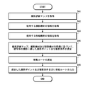
- FIG. 2 is a block diagram showing a schematic configuration of a shooting evaluation map generation apparatus realized by installing a shooting evaluation map generation program in a computer.
- Block diagram of functions realized by shooting evaluation map generation device The figure which shows an example of the setting of coordinate space The figure which shows an example of a setting of imaging
- the shooting evaluation map generating device has a shooting evaluation map in which an evaluation value indicating shooting evaluation when a subject is shot from a specific position under a specific shooting condition is determined for each of a plurality of shooting conditions for a plurality of shooting candidate positions. Is generated.
- the shooting evaluation map generation device is configured by a computer in which a predetermined shooting evaluation map generation program is installed.
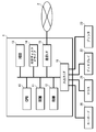
- FIG. 1 is a block diagram showing a schematic configuration of a shooting evaluation map generation apparatus realized by installing a shooting evaluation map generation program in a computer.
- the imaging evaluation map generating device 1 includes a CPU (Central Processing Unit) 10, a ROM (Read Only Memory) 11, a RAM (Random Access Memory) 12, a hard disk drive (Hard Disk Drive, HDD) 13, An optical disk drive 14, a communication interface (interface, I / F) 15, an input / output interface (interface, I / F) 16, and the like are provided.
- a CPU Central Processing Unit
- ROM Read Only Memory
- RAM Random Access Memory
- HDD Hard Disk Drive
- An optical disk drive 14 a communication interface (interface, I / F) 15, an input / output interface (interface, I / F) 16, and the like are provided.
- the photographing evaluation map generation device 1 is connected to the network 2 via the communication interface 15 and connected to other devices such as a server via the network 2 so as to be communicable.
- the imaging evaluation map generating device 1 is connected to input devices such as a keyboard 20 and a mouse 21 via an input / output interface 16. Further, an output device such as a display 22 and a printer 23 is connected to the photographing evaluation map generating device 1 through an input / output interface 16.
- the shooting evaluation map generation program is recorded and distributed on a non-transitory computer-readable medium (recording medium) such as a DVD (Digital Versatile Disc) or a CD-ROM (Compact Disk Read Only Memory). To be installed. Alternatively, it is stored on the network in a state where it can be accessed from the outside, downloaded to a computer upon request, and installed on the computer.
- a non-transitory computer-readable medium such as a DVD (Digital Versatile Disc) or a CD-ROM (Compact Disk Read Only Memory).
- recording medium such as a DVD (Digital Versatile Disc) or a CD-ROM (Compact Disk Read Only Memory).
- DVD Digital Versatile Disc
- CD-ROM Compact Disk Read Only Memory
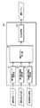
- FIG. 2 is a block diagram of functions realized by the imaging evaluation map generation device.
- the imaging evaluation map generating apparatus 1 includes a coordinate space setting unit 31 that sets a coordinate space, a shooting candidate position setting unit 32 that sets a shooting candidate position, a shooting condition setting unit 33 that sets shooting conditions, and a feature part that sets a feature part.
- the coordinate space setting unit 31 sets a coordinate space including the subject.
- the coordinate space setting unit 31 receives input of subject information and sets a coordinate space. For example, when a three-dimensional structure is used as a subject, input of the three-dimensional model data is accepted and a coordinate space is set. Further, for example, when a plane is an object, input of plane data (plane image data, map data, etc.) is accepted and a coordinate space is set.
- plane data plane image data, map data, etc.
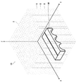
- FIG. 3 is a diagram showing an example of setting the coordinate space.
- the coordinate space CS is defined by three orthogonal axes (X axis, Y axis, and Z axis), and is set to include the entire subject OB to be imaged.
- the shooting candidate position setting unit 32 sets shooting candidate positions.
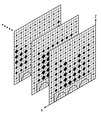
- a plurality of photographing candidate positions are set in the coordinate space set by the coordinate space setting unit 31.
- a finite space including the subject OB is divided into a plurality of blocks B, and the position of the center of each block B is set as a photographing candidate position.
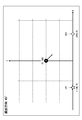
- FIG. 4 is a diagram illustrating an example of setting of photographing candidate positions. This figure shows an example of setting of the photographing candidate position in a specific XZ section. This figure shows an example in which a finite space S including the subject OB is divided into a plurality of blocks B and set to the photographing candidate position PP (Xn, Yn, Zn) at the center position of each block B. ing.
- the photographing candidate position setting unit 32 automatically sets the photographing candidate position based on the set coordinate space.
- the shooting condition setting unit 33 sets shooting conditions for the subject.
- the imaging conditions refer to various parameter groups that affect the imaging results, such as the imaging direction (the direction of the lens optical axis), the imaging field angle (focal length), the number of recording pixels, the imaging wavelength, and the positional relationship with the light source.
- the shooting condition setting unit 33 automatically sets a plurality of shooting conditions. For example, a plurality of shooting conditions are automatically set by changing the shooting direction (the direction of the lens optical axis), the shooting angle of view (focal length), the number of recording pixels, and the like.
- the feature part setting unit 34 sets a plurality of feature parts for the subject.
- the “characteristic part” of the subject is the “appearance (appearance (appearance, appearance, appearance))” of the object directly or indirectly related to “information about the object”.
- the three-dimensional shape of the inspection target object which is the subject, the texture of the surface, and the like are typical feature parts.
- Specific components of a three-dimensional shape that is useful “appearance” include vertices, ridge lines, and the like.
- specific components of the surface texture that are useful “appear” include surface contamination (stains, discoloration, etc.), degradation sites such as cracks.
- points, lines, and regions that are useful “appearances” of the subject are characteristic portions.
- the positions, orientations, and the like of the points, lines, and regions that are set as feature parts are specified on the coordinate space.
- the range (size) is specified.
- the direction is the direction in which the characteristic part is facing.
- the feature part setting unit 34 automatically sets a feature part based on the data of the subject. For example, vertices, ridge lines, etc. are automatically extracted from the three-dimensional model data of the subject, and the extracted vertices, ridge lines, etc. are set as feature parts. Also, for example, feature points are automatically extracted from planar image data, and the extracted feature points are set as feature parts.
- the feature part setting unit 34 receives the specification of the feature part from the user and sets the feature part. For example, a three-dimensional model (for example, a triangular mesh model) of the subject is displayed on the display 22 and designation (position and orientation) of a part as a characteristic part is accepted. Alternatively, an image group obtained by photographing the subject from a plurality of viewpoints is displayed on the display 22, and designation of a part to be a characteristic part on the image is accepted. The user designates a part as a characteristic part by designating with a cursor or the like. For example, a feature region is designated by designating a region where a deterioration phenomenon such as dirt or a crack appears or a region assumed to appear.
- a three-dimensional model for example, a triangular mesh model
- designation position and orientation
- an image group obtained by photographing the subject from a plurality of viewpoints is displayed on the display 22, and designation of a part to be a characteristic part on the image is accepted.
- the user designates a
- the feature part setting unit 34 receives an instruction from the user and cancels the setting of the feature part that has been automatically set.
- the evaluation criterion setting unit 35 sets an evaluation criterion for evaluating photographing.
- This evaluation standard is an evaluation standard based on each characteristic part. That is, the quality of imaging is evaluated from the viewpoint from each characteristic part. Therefore, it is individually set for each characteristic part.
- the evaluation standard is defined by a function (evaluation function) having the position and shooting conditions as parameters. Therefore, the element used as a parameter in this evaluation function is a shooting condition set by the shooting condition setting unit 33. Therefore, for example, when the shooting direction, the shooting angle of view, and the number of recorded pixels are parameters of the evaluation function, the shooting condition setting unit 33 sets at least the shooting direction, the shooting angle of view, and the number of recorded pixels as the shooting conditions. .
- the evaluation standard is set so that a relatively high evaluation is calculated with respect to the position and imaging conditions where the characteristic part for which the evaluation standard is set is satisfactorily imaged. For example, in the case of a characteristic part that can be photographed better from the front rather than from the oblique direction, a relatively high evaluation is given for the condition photographed from the front rather than the condition photographed from the oblique direction. Set to be calculated.
- the evaluation criterion setting unit 35 individually sets the evaluation function for each characteristic part based on a predetermined setting rule. For example, the evaluation function of each characteristic part is individually set so that a relatively high evaluation can be obtained with respect to imaging from the front. The evaluation function for each characteristic part is individually set so that a relatively high evaluation can be obtained with respect to the images laid out in the center of the screen. The evaluation function for each characteristic part is individually set so that a relatively high evaluation can be obtained for the image captured at a predetermined size in the screen.
- the evaluation value calculation unit 36 calculates an evaluation value representing an evaluation of shooting when each subject is shot from each shooting candidate position under each set shooting condition for each shooting candidate position and each shooting condition.
- the evaluation value is calculated as the sum of the evaluations obtained by evaluating the imaging at the imaging candidate position and the imaging conditions to be evaluated at all the characteristic parts. That is, imaging is evaluated from the viewpoint of each characteristic part, and the sum total of evaluations from the obtained characteristic parts is set as an evaluation value of the imaging. For example, it is assumed that an image is taken from a certain photographing candidate position under certain photographing conditions.
- the imaging is evaluated individually for all the characteristic parts. In this case, various evaluations are made from each characteristic part.
- the sum total of the evaluation of all the characteristic parts becomes the evaluation value of the imaging to be evaluated.
- the evaluation value calculation unit 36 calculates an evaluation value according to the following procedure.
- the evaluation value calculation unit 36 specifies a photographing candidate position and a photographing condition to be evaluated.
- the evaluation value calculation unit 36 obtains an evaluation obtained from each characteristic part when the image is taken under the specified conditions. This evaluation is calculated as an individual evaluation value, and is calculated for all feature parts.
- the individual evaluation value is calculated according to an evaluation standard defined for each characteristic part. As described above, the evaluation criterion is defined as an evaluation function using the position and the shooting conditions as parameters. Therefore, the evaluation value calculation unit 36 substitutes the specified imaging candidate position and imaging conditions for the evaluation function, and calculates the individual evaluation value of each feature part. When the individual evaluation values are obtained for all the characteristic parts, the evaluation value calculation unit 36 obtains the sum. The obtained sum is taken as an evaluation value at the photographing candidate position and photographing conditions to be evaluated.
- FIG. 5 is a graph showing the relationship between individual evaluation values and evaluation values obtained when shooting is performed under certain shooting conditions from a certain shooting candidate position.
- the shooting evaluation map generation unit 37 generates a shooting evaluation map based on the calculation result of the evaluation value calculation unit 36.
- a shooting evaluation map is generated in which an evaluation value representing shooting evaluation when a subject is shot from a specific position under a specific shooting condition is determined for each of a plurality of shooting conditions for a plurality of shooting candidate positions.
- the evaluation value calculation unit 36 calculates an evaluation value representing the evaluation of shooting for each shooting candidate position and shooting condition.
- the shooting evaluation map generation unit 37 generates a shooting evaluation map based on the calculation result of the evaluation value calculation unit 36.
- the shooting evaluation map is generated in a predetermined format, and at least evaluation value information is generated and the shooting candidate position and shooting condition information from which the evaluation value is calculated are associated with each other.
- FIG. 6 is a diagram showing an example of the data structure of the shooting evaluation map.
- the shooting evaluation map data includes at least shooting candidate positions PP (X1, Y1, Z1) to PP (Xn, Yn, Zn) information, shooting conditions SC1 to SCn information, and evaluation.
- the information of the evaluation values ⁇ 1 (X1, Y1, Z1) to ⁇ n (Xn, Yn, Zn) is the imaging candidate position where the evaluation values ⁇ 1 (X1, Y1, Z1) to ⁇ n (Xn, Yn, Zn) are calculated.
- the information is recorded in association with the information of PP (X1, Y1, Z1) to PP (Xn, Yn, Zn) and the information of photographing conditions SC1 to SCn.
- the shooting evaluation map output processing unit 38 outputs the generated shooting evaluation map to the output device in a predetermined output format.
- the shooting evaluation map is output in a table format, a graph format, or the like, for example.
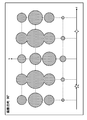
- FIG. 7 is a diagram showing an example when the shooting evaluation map is displayed in a graph format.
- This figure shows a graph of evaluation values according to photographing conditions in a certain XZ plane.
- the circle displayed on each graph indicates the evaluation value at that position (imaging candidate position), and the higher the diameter, the higher the evaluation value.
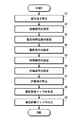
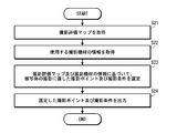
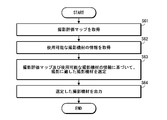
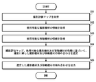
- FIG. 8 is a flowchart showing a procedure for generating a shooting evaluation map.
- a subject to be imaged is specified (step S1).
- the subject is specified by inputting subject data.
- subject data For example, the subject 3D model data, plane data, etc. are input and specified.
- step S2 a coordinate space including the subject is set (step S2).
- step S3 a plurality of photographing candidate positions are set in the set coordinate space.
- shooting conditions are set (step S4).
- the shooting conditions are set based on the parameters of the evaluation function. For example, when the evaluation function uses the shooting angle of view and the shooting direction as parameters, conditions for the shooting angle of view and the shooting direction are set. At this time, a plurality of shooting conditions having different contents are set. For example, a plurality of shooting conditions with different shooting angles or shooting directions are set. Alternatively, a plurality of shooting conditions with different shooting angles and shooting directions are set.
- a characteristic part is set (step S5).
- the characteristic part is automatically set based on subject data. That is, a part that is useful is automatically extracted and set as a characteristic part. Moreover, it is set manually as necessary.
- an evaluation standard is set for each set feature part (step S6).
- the evaluation standard is defined by an evaluation function using the position and shooting conditions as parameters.
- the evaluation function of the characteristic part is set so that a relatively high evaluation is calculated with respect to a condition in which the characteristic part is well imaged.
- an evaluation value is calculated based on the set imaging candidate position, imaging conditions, characteristic part, and evaluation function (step S7).
- the evaluation value is calculated for each shooting candidate position and each shooting condition.
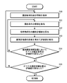
- FIG. 9 is a flowchart showing an evaluation value calculation procedure.
- the evaluation value is calculated for each shooting candidate position by switching shooting conditions. That is, when the evaluation values for all the shooting conditions are calculated for one shooting candidate position, the evaluation value for the next shooting candidate position is calculated.
- step S10 information on the first photographing candidate position is acquired (step S10).
- step S11 information on the first imaging condition is acquired (step S11).
- step S12 an individual evaluation value of each feature part is calculated based on the acquired imaging candidate position and imaging conditions (step S12).
- the individual evaluation value of each characteristic part is calculated by substituting information on the imaging candidate position and imaging conditions into the evaluation function. After calculating the individual evaluation values of all the characteristic parts, the sum is calculated and set as the evaluation value under the condition (step S13).
- step S14 it is determined whether or not the evaluation values for all shooting conditions have been calculated for the shooting candidate position. If the evaluation values for all the shooting conditions are not completed, the process returns to step S11 to acquire information on the next shooting condition. Then, an evaluation value is calculated under the obtained photographing conditions.
- step S15 If calculation of evaluation values for all shooting conditions is completed for the shooting candidate position, it is next determined whether or not evaluation values have been calculated for all shooting candidate positions (step S15). If the calculation of the evaluation values is not completed for all the photographing candidate positions, the process returns to step S10, and information on the next photographing candidate position is acquired. Then, the shooting conditions are switched under the acquired shooting candidate positions, and the respective evaluation values are calculated. When the calculation of the evaluation values is completed for all the photographing candidate positions, the process ends.
- a shooting evaluation map is generated based on the calculation result (step S8).
- the shooting evaluation map is generated in a predetermined format, and at least evaluation value information and a shooting candidate position and shooting condition information for which the evaluation value is calculated are associated with each other (see FIG. 6). ).
- the generated shooting evaluation map is output to the output device in a predetermined output format (step S9).
- the data is output to the display 22 in a graph format (see FIG. 7).
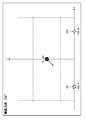
- FIG. 10 is a diagram illustrating an example of a subject.
- a specific area on the ground surface is the subject OB.
- a plane including the subject OB that is a plane is set as a ZX plane, and a plane orthogonal to the ZX plane is set as an XY plane.
- the X axis, the Y axis, and the Z axis are set so as to pass through the center of the subject OB, respectively.
- the photographing candidate position is set in the set coordinate space. As described above, in this example, shooting is performed while moving in a two-dimensional space. Therefore, the photographing candidate position is set in the two-dimensional space. In this example, a photographing candidate position is set on the XY plane. A photographing candidate position is represented by a coordinate position (x, y).
- Feature Part As described above, a part that appears in “appearance” is set as the feature part. As shown in FIG. 10, it is assumed that two parts appear as “visible” on the subject OB. In this case, a part that appears as “appearance” is set as a characteristic part. One feature part is referred to as a first feature part CP1, and the other feature part is referred to as a second feature part CP2.
- An evaluation function for each feature part is set as an evaluation reference for each feature part.
- the evaluation function is the shooting candidate position (x, y).
- a function having the shooting direction ⁇ as a parameter is set.
- the “photographing distance suitable for photographing the characteristic part” varies depending on the resolving ability of the photographing equipment to be used, the photographing object, and the like, and is appropriately set in consideration of these factors.
- the imaging direction suitable for imaging of the characteristic part also varies depending on the imaging target and the like, it is appropriately set in consideration of the imaging target and the like. Generally, photographing from the front, that is, photographing in front is more preferable.
- Evaluation function based on each criterion >> (A) Evaluation function based on criterion a (evaluation criterion relating to imaging position) (A1) Evaluation function of first feature region CP1 based on criterion a The evaluation function of first feature region CP1 based on criterion a is expressed as f1a (x, y, ⁇ ).
- the distance (shooting distance) between each imaging candidate position (x, y) and the first feature part CP1 is the sum of squares of the differences d1.
- d1 (X ⁇ x1) 2 + (y ⁇ y1) 2
- an imaging distance suitable for imaging the first characteristic part CP1 is D1
- this numerical value becomes smaller as it is closer to D1.
- the evaluation function f1a (x, y, ⁇ ) of the first characteristic part CP1 based on the reference a can be set as the following expression, for example.
- the imaging distance suitable for imaging the second characteristic part CP2 is D2
- the evaluation function f2a (x, y, ⁇ ) of the second feature part CP2 based on the reference a can be set as the following expression, for example.
- the evaluation function f1b (x, y, ⁇ ) of the first characteristic part CP1 based on the reference b can be set as follows, for example.
- f1b (x, y, ⁇ ) 1.0 ⁇
- f2b (x, y, ⁇ ) be an evaluation function of the second feature part CP2 based on the reference b.
- the evaluation function f2b (x, y, ⁇ ) of the second feature part CP2 based on the reference b can be set as follows, for example.
- the evaluation function set for each feature part is the individual evaluation function f1a (x, y, ⁇ ), f1b (x, y, ⁇ ), f2a (x, y, ⁇ ), f2b ( x, y, ⁇ ) in combination.
- the product is set as follows.
- Evaluation function F1 (x, y, ⁇ ) of the first characteristic part CP1 F1 (x, y, ⁇ ) f1a (x, y, ⁇ ) ⁇ f1b (x, y, ⁇ )
- Evaluation function F2 (x, y, ⁇ ) of the second characteristic part CP2 F2 (x, y, ⁇ ) f2a (x, y, ⁇ ) ⁇ f2b (x, y, ⁇ )
- the sum is calculated and set as follows.
- Evaluation function F1 (x, y, ⁇ ) of the first characteristic part CP1 F1 (x, y, ⁇ ) f1a (x, y, ⁇ ) + f1b (x, y, ⁇ )
- Evaluation function F2 (x, y, ⁇ ) of the second characteristic part CP2 F2 (x, y, ⁇ ) f2a (x, y, ⁇ ) + f2b (x, y, ⁇ )
- a weighted sum is calculated and set as follows (k1 and k2 are weights).
- Evaluation function F1 (x, y, ⁇ ) of the first characteristic part CP1 F1 (x, y, ⁇ ) k1 ⁇ f1a (x, y, ⁇ ) + k2 ⁇ f1b (x, y, ⁇ )
- Evaluation function F2 (x, y, ⁇ ) of the second characteristic part CP2 F2 (x, y, ⁇ ) k1 ⁇ f2a (x, y, ⁇ ) + k2 ⁇ f2b (x, y, ⁇ ) (6) Calculation of evaluation value
- the evaluation function F (X, Y, ⁇ ) Is set as follows:
- the evaluation value can be calculated by inputting information about the imaging candidate position and the imaging condition to be evaluated into the evaluation function F (X, Y, ⁇ ).
- An example of evaluation value calculation is shown below.
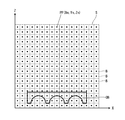
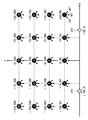
- FIG. 11 is a diagram showing an example of setting of the shooting candidate position and shooting conditions (shooting direction).
- the evaluation value of each shooting condition (shooting direction) at each shooting candidate position is calculated in an example in which 20 shooting candidate positions and three shooting conditions (shooting directions) are used.
- the photographing candidate positions (x, y) are set to a total of 20 positions, 4 positions at equal intervals in the vertical direction (y direction) and 5 positions at equal intervals in the horizontal direction (x direction).
- the lower right photographing candidate position is defined as a first photographing candidate position
- the upper left photographing candidate position is defined as a twentieth photographing candidate position.
- the shooting direction ( ⁇ ), which is a shooting condition, is set to 45 °, 90 °, and 135 °. It is assumed that 90 ° is the shooting direction in the vertical direction.
- an imaging distance D1 suitable for imaging the first feature site CP1 is 140
- an imaging distance D2 suitable for imaging the second feature site CP2 is 140.
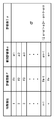
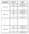
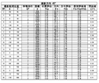
- FIG. 12 is a table showing a list of evaluation values obtained at each photographing candidate position when the photographing direction is 45 °.
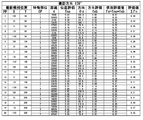
- FIG. 13 is a table showing a list of evaluation values obtained at each photographing candidate position when the photographing direction is 90 °.
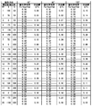
- FIG. 14 is a table showing a list of evaluation values obtained at each photographing candidate position when the photographing direction is 135 °.
- the column “shooting candidate position” represents the number of the shooting candidate position (see FIG. 11) and its coordinates (x, y).
- the “characteristic part” column indicates the characteristic part number. “1” represents the first feature portion and “2” represents the second feature portion.
- the “distance” column represents the distance of each imaging candidate position with respect to each characteristic part.
- the column “Position Evaluation” represents an evaluation value calculated by the evaluation function fna based on the criterion a (evaluation criterion relating to the shooting position).
- the “direction” column represents the angle of a straight line connecting each imaging candidate position and each characteristic part.
- the column of “direction evaluation” represents an evaluation value calculated by the evaluation function fnb based on the criterion b (evaluation criterion regarding the shooting direction).
- the column of “Individual evaluation value” indicates the evaluation value at each characteristic part.
- a shooting evaluation map is generated based on the calculation result of the evaluation value.
- FIG. 15 is a diagram showing an example of the data structure of the shooting evaluation map.
- the evaluation value obtained for each photographing condition is associated with information on the photographing candidate position and information on the photographing condition (photographing direction). To be recorded.
- information on individual evaluation values when the evaluation values are obtained is also recorded.
- Output of shooting evaluation map The generated shooting evaluation map is output to an output device in a predetermined output format.
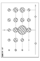
- FIG. 16 to 18 are diagrams showing an example of the case where the evaluation values obtained at each photographing candidate position are graphed according to photographing conditions and output.
- FIG. 16 is a diagram illustrating an example of a case where the evaluation value obtained at each photographing candidate position is graphed and output when the photographing direction is 45 °.
- FIG. 17 is a diagram illustrating an example of a case where the evaluation value obtained at each photographing candidate position is graphed and output when the photographing direction is 90 °.
- FIG. 18 is a diagram illustrating an example of a case where the evaluation value obtained at each photographing candidate position is graphed and output when the photographing direction is 135 °.
- a circle displayed on the graph indicates an evaluation value at that position (imaging candidate position), and indicates that the higher the diameter, the higher the evaluation value.
- shooting direction is 90 °
- shooting at the shooting candidate position (75, 100) and shooting candidate position ( ⁇ 75, 100) has the highest evaluation.
- the 3D model can be generated using a known method such as SfM (Structure from Motion).
- SfM is a technique for reproducing a three-dimensional model of a subject from a plurality of images (a multi-viewpoint image) obtained by shooting the subject from a plurality of viewpoints.
- the shooting evaluation map generation device When realizing a function for generating a three-dimensional model of a subject in the shooting evaluation map generation device, the shooting evaluation map generation device includes a subject image acquisition unit that acquires a plurality of images obtained by shooting the subject from a plurality of viewpoints, and A three-dimensional model generation unit that generates a three-dimensional model of the subject based on the plurality of images is further provided.
- the subject image acquisition unit and the 3D model generation unit are realized by a computer executing a predetermined program.
- the three-dimensional model generation unit generates a three-dimensional model (for example, a three-dimensional mesh model) using a known method such as SfM.
- the coordinate space setting unit 31 acquires information on the three-dimensional model of the subject generated by the three-dimensional model generation unit, and sets the coordinate space based on the obtained three-dimensional model.
- ⁇ Modification of shooting candidate position setting unit It is preferable to set the shooting candidate position set by the shooting candidate position setting unit 32 in consideration of the shooting target, shooting purpose, and the like. Further, the photographing candidate position may be set manually. Further, the shooting candidate position may be set on a straight line in consideration of the case of moving and shooting on a straight line. Further, in consideration of the case of shooting while moving in the plane, the configuration may be set in the plane.
- the shooting conditions set by the shooting condition setting unit 33 may be automatically set according to the subject, or may be set appropriately by the user. In addition, the user may appropriately modify the shooting conditions automatically set according to the subject. In the case of automatic setting, it is preferable to automatically select necessary shooting conditions in consideration of the shooting target, shooting purpose, and the like.
- a plurality of shooting conditions having different contents can be set for one item.
- a plurality of shooting conditions with different shooting directions can be set.
- a plurality of evaluation values with different shooting directions are obtained for the same shooting candidate position.
- a plurality of shooting conditions with different shooting angles of view may be set. Thereby, a plurality of evaluation values having different shooting angles of view are obtained for the same shooting candidate position.
- a function of switching the shooting angle of view zoom function
- changing the shooting angle of view is synonymous with changing the focal length.
- a plurality of shooting conditions may be set by changing the number of recording pixels. Thereby, a plurality of evaluation values with different numbers of recording pixels are obtained for the same photographing candidate position. This makes it easy to select equipment suitable for shooting.
- the number of recorded pixels is the number of pixels when a captured image is recorded on a medium.
- it is synonymous with resolution. That is, the higher the number of recorded pixels, the higher the resolution.
- a plurality of shooting conditions with different exposure correction amounts may be set. Thereby, a plurality of evaluation values having different exposure correction amounts are obtained for the same photographing candidate position. Thereby, for example, when shooting with equipment capable of correcting exposure, the shooting plan can be easily formulated.
- a plurality of shooting conditions with different frame rates may be set. Thereby, a plurality of evaluation values having different frame rates are obtained for the same photographing candidate position. This makes it easy to select equipment suitable for shooting.
- ⁇ Modification of characteristic part setting unit ⁇ parts (points, lines, and regions) that are useful “appearances” of the subject are taken as characteristic parts.
- the characteristic part is preferably set in consideration of the subject to be photographed, the purpose of photographing and the like.
- the three-dimensional shape (vertex, ridgeline, etc.) of the subject and the texture of the surface (degraded part of the surface, cracks, etc.) are the typical characteristic parts when photographing for the purpose of checking the structure.
- vertex, ridgeline, etc. information on the vertex, ridgeline, etc. is obtained from the design data (drawings, CAD (Computer Aided Design) data, etc.) of the subject structure And set it as a characteristic part. It is also possible to measure (survey) the actual product, acquire information on the positions and orientations of the vertices and ridges, and set the information as feature regions.
- the surface texture (deteriorated part of surface dirt, cracks, etc.) is a characteristic part
- the deterioration of dirt, cracks, etc. from the data (drawings, CAD data, etc.) at the time of designing the structure to be the subject It is possible to set a characteristic part by estimating a place where a phenomenon may occur and specifying its position, orientation, and size (range). Alternatively, it is possible to visually observe the actual product, find a spot where dirt, cracks, etc. are generated, and use it as a characteristic part.
- the characteristic part can also be set with reference to the past photographing history.
- the characteristic part can also be set with reference to the past photographing history. For example, in the case of shooting for the purpose of inspection of a structure, when the structure has been shot in the past, information on the deteriorated part can be acquired by referring to the past shooting history and set as a characteristic part. .
- a part that becomes a feature part can be automatically extracted from the subject and set as the feature part. For example, when the imaging evaluation map is generated for the purpose of inspecting a structure or the like, the feature part can be set in the next step.
- First step First, a plurality of images obtained by photographing a subject from a plurality of viewpoints are acquired.
- Second step Next, vertices and ridge lines useful for estimating the three-dimensional structure or shape of the subject are extracted from the obtained image group.
- a texture (not limited to dirt, cracks, etc.) related to the surface shape of the subject is extracted.
- the extraction process uses a known image recognition technique.
- Third step Next, the three-dimensional structure or shape of the subject is estimated based on the information obtained in the second step.
- elements useful for inspection are extracted from the three-dimensional structure or shape of the subject obtained in the third step by image processing.
- image processing For example, an image recognition technique is used to recognize dirt, cracks, and the like and extract elements useful for inspection.
- the position, orientation, and range (size) of the extracted element are specified and set as a characteristic part.
- the feature part can be set in the next step.
- First step First, a plurality of images obtained by photographing a subject from a plurality of viewpoints are acquired.
- Second step Next, feature points are roughly detected from the obtained image group by a technique such as SfM to obtain point cloud data.
- Third step Next, a point cloud distribution is analyzed from the obtained point cloud data to generate a three-dimensional mesh model.
- Vertices and ridge lines are extracted from the generated three-dimensional mesh model and set as feature parts.
- the photographing evaluation map generation device includes a subject image acquisition unit that acquires a plurality of images obtained by photographing a subject from a plurality of viewpoints, and a three-dimensional model of the subject based on the plurality of images obtained.
- a three-dimensional model generation unit is further provided.
- the subject image acquisition unit, the three-dimensional model generation unit, and the feature part extraction unit are realized by a computer executing a predetermined program.
- a part that can be a characteristic part is extracted from a plurality of images obtained by photographing a subject from a plurality of viewpoints and information of three-dimensional model data generated from the image group. It is good also as composition to do.
- the characteristic part can also be set with reference to the past photographing history. For example, in the case of shooting for the purpose of inspection of the structure, if the structure has been shot in the past, the past shooting information is acquired, and the information on the deteriorated part is automatically extracted from the obtained information Then, the characteristic part may be set automatically.
- the feature part When the feature part is automatically set, the user may manually add or delete the feature part as necessary. That is, the feature part may be set by combining automatic and manual. Thereby, a mutual fault can be complemented and a characteristic part can be set efficiently.
- the evaluation criteria may be set manually or may be set automatically.
- the evaluation standard is set so that the characteristic part of the part where the mesh direction is dispersed (the part with severe unevenness) is highly evaluated for photographing from an oblique direction as well as the front.
- the evaluation criteria for each feature part is set using the feature point information obtained in the process of generating the three-dimensional model. It is preferable. For example, it is possible to set an evaluation criterion for each feature part using information on the density of detected feature points. For example, an evaluation criterion is set so that a high-resolution image is highly evaluated for a feature part at a high density of feature points.
- an evaluation criterion is set such that the higher the resolution is, the higher the evaluation is.
- an evaluation criterion is set so as to be highly evaluated for photographing not only from the front but also from an oblique direction.
- the feature part of the point that should be photographed must be highly evaluated for the conditions (photographing position and / or photographing direction) that ensure that the feature part is photographed. Evaluation criteria are set so that
- the evaluation function can be generated by setting a standard for evaluation, setting a function for each predetermined standard, and appropriately combining the set functions.
- a function that evaluates the position, a function that evaluates the shooting direction, and a function that evaluates the shooting angle of view are set.
- Generate an evaluation function. The combination is set according to the evaluation mode. If each item is highly evaluated at the same time, the evaluation function is generated by multiplying the functions of the functions.
- an evaluation function that takes the sum of each function is generated.
- a weight is assigned and an evaluation function is generated. For example, in the above example, when importance is attached to the shooting direction, a relatively high weight is assigned to a function for evaluating the shooting direction, and an evaluation function is generated by taking the sum of the functions.
- the evaluation value is calculated as the sum of the evaluation values (individual evaluation values) obtained at all the characteristic parts.
- a weight may be given to each feature part. For example, in the case where a photographing evaluation map is generated for the purpose of inspection of a structure and the like, when a deteriorated part (dirt, crack, etc.) on the surface of the structure is a characteristic part, it is relatively higher than the deteriorated part An evaluation value may be calculated by assigning a weight. Alternatively, the evaluation value may be calculated by assigning a relatively high weight to the feature part designated as the part to be noted.
- the imaging evaluation map generation device When calculating an evaluation value by assigning a weight to each feature part, the imaging evaluation map generation device further includes a weight setting unit.
- the weight setting unit sets a weight for each feature part.
- the weight setting unit is realized by a computer executing a predetermined program.
- the evaluation value calculation unit 36 calculates, as the evaluation value, a sum obtained by multiplying the obtained individual evaluation value for each feature part by the weight when calculating the evaluation value.
- the weighting unit when generating an imaging evaluation map for the purpose of inspecting a structure, acquires information on a deteriorated part set as a characteristic part and assigns a relatively high weight to the deteriorated part. .
- a weight can be given to each characteristic part using the past imaging information. For example, a relatively high weight is given to a characteristic portion of a point that should be photographed from past photographing information.
- information about past damage history can be acquired, a weight can be appropriately given to the characteristic part from the information.
- a target region selection unit is separately provided.
- the attention site selection unit performs a process of selecting a target region (target region) from among the plurality of set feature regions. The selection is performed, for example, by displaying a plurality of set feature parts on the display 22 and allowing the user to select a feature part as a target part.
- the weight assigning unit assigns a relatively high weight to the selected site of interest.
- weight given to each feature part may be manually given. Moreover, it is preferable that the set weight can be appropriately adjusted.
- the shooting evaluation map generated by the shooting evaluation map generating unit 37 only needs to include at least evaluation value information and shooting candidate positions and shooting condition information from which the evaluation values are calculated. Furthermore, by recording useful information in association with the evaluation value, a more useful shooting evaluation map can be generated.
- the generated shooting evaluation map is not necessarily displayed and may be output as data.
- processing such as display, processing for generating a shooting plan using a shooting evaluation map, and the like are performed by an external device that has acquired the data.
- Photographing device ⁇ In the shooting evaluation map, an evaluation value representing shooting evaluation when a subject is shot from a specific position under a specific shooting condition is determined for each of a plurality of shooting conditions for a plurality of shooting candidate positions. Therefore, by taking this shooting evaluation map into consideration, it is possible to determine from which position and under what shooting conditions a good image can be shot.
- the photographing apparatus is composed of a computer in which a predetermined photographing program is installed.
- the hardware configuration is substantially the same as the hardware configuration of the above-described imaging evaluation map generation device (see FIG. 1). Therefore, description of the specific configuration is omitted here.
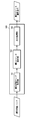
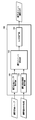
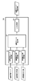
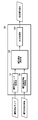
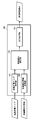
- FIG. 19 is a block diagram of functions realized by the photographing apparatus.
- the imaging apparatus 100 includes an imaging evaluation map acquisition unit 101 that acquires an imaging evaluation map, and an imaging point selection unit that selects an imaging point and an imaging condition at the imaging point based on the acquired imaging evaluation map. And an output processing unit 103 that outputs the selected shooting point and shooting conditions.
- the shooting evaluation map acquisition unit 101 acquires a shooting evaluation map.
- the photographing evaluation map acquisition unit 101 acquires the photographing evaluation map generated by the photographing evaluation map generating apparatus as it is. That is, a shooting evaluation map is acquired directly from the shooting evaluation map generation unit 37.
- it acquires using the optical disc drive 14, the communication interface 15, the input / output interface 16, etc. (refer FIG. 1).
- a shooting evaluation map generated for the purpose of shooting for inspection of the structure is acquired.
- the three-dimensional shape (vertex, ridge line, etc.) of the structure that is the subject, the surface texture (degraded part such as dirt, cracks, etc.), etc. are set as characteristic parts.
- the shooting point selection unit 102 selects a shooting point (shooting position) suitable for shooting a subject and shooting conditions at the shooting point based on the shooting evaluation map acquired by the shooting evaluation map acquisition unit 101.
- the shooting point selection unit 102 extracts a condition with a high evaluation value (a combination of shooting candidate positions and shooting conditions) from the shooting evaluation map, and selects shooting points and shooting conditions so as to satisfy the conditions. For example, conditions up to the top N evaluation values (combination of shooting candidate positions and shooting conditions) are extracted, and shooting points and shooting conditions are selected so as to satisfy the extracted conditions. Alternatively, a condition (combination of photographing candidate positions and photographing conditions) having an evaluation value equal to or greater than a threshold is extracted, and photographing points and photographing conditions are selected so as to satisfy the extracted conditions.
- the simplest selection method is a method in which the extracted shooting candidate position and its shooting conditions are directly set as the shooting point and the shooting conditions.
- shooting points and shooting conditions are selected as follows.
- the position (75, 150) and the position ( ⁇ 75, 150) are suitable shooting points.
- the position (x1, D1) and the position (x2, D2) are set as preferable imaging points (the coordinate position of the first characteristic part CP1 is (x1, y1), the first An imaging distance D1 suitable for imaging of one feature site CP1, a coordinate position of the second feature site CP2 is (x2, y2), and an imaging distance D2 suitable for imaging the second feature site CP2.
- photographing that changes the photographing direction at the position (0, 100) is a preferable condition. That is, at the position (0, 100), shooting performed at a shooting direction of 45 ° and shooting performed at a shooting direction of 135 ° are preferable conditions. Furthermore, an imaging point can be selected in consideration of an imaging distance suitable for imaging each characteristic part.
- the cost of moving is higher than the cost required to change the shooting direction (high power consumption).
- power consumption is consumed in the order of ascending> level flight> hovering> descending.
- the output processing unit 103 outputs the shooting points and shooting conditions selected by the shooting point selection unit 102 in a predetermined output format.
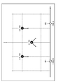
- FIG. 20 is a diagram showing an example of outputting the selected shooting point and shooting conditions to the display.
- the shooting candidate positions selected as shooting points and the shooting conditions are displayed on the display 22.
- information on the shooting direction which is a shooting condition, is indicated by the direction of the arrow extending from each shooting candidate position.
- FIGS. 21 to 23 show another example of outputting the selected shooting point and shooting conditions to the display.
- FIGS. 21 to 23 show an example in which the selected shooting points are displayed according to shooting conditions.
- FIG. 21 shows a display example when the shooting direction is 45 °.
- FIG. 22 shows a display example when the shooting direction is 90 °.
- FIG. 23 shows a display example when the shooting direction is 135 °.
- the selected conditions can be easily identified by displaying according to the shooting conditions in this way.
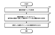
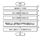
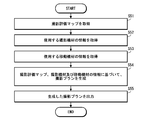
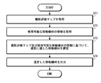
- FIG. 24 is a flowchart showing a procedure for selecting a shooting point and shooting conditions.
- a shooting evaluation map is acquired (step S11).
- a shooting point suitable for shooting the subject and shooting conditions at the shooting point are selected (step S12).
- the selected shooting point and shooting conditions are output (step S13). The user formulates a shooting plan based on the output shooting point and shooting condition information.
- a travel route For the selection of the movement route, for example, an algorithm for solving a known combination optimization problem can be adopted. For example, an algorithm that solves the traveling salesman problem can be adopted to select a travel route.
- ⁇ Modification> For selection of shooting points and shooting conditions, for example, a learned model generated using a learning data set based on an evaluation map may be used.
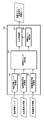
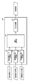
- FIG. 25 is a block diagram of functions realized by the imaging apparatus according to the second embodiment.
- the photographing apparatus 100 further includes a photographing equipment information acquisition unit 104 that obtains information on the photographing equipment to be used, and takes a photographing point and a photographing in consideration of the information on the photographing equipment to be used. It is different from the photographing apparatus 100 of the first embodiment in that the conditions are selected. Therefore, in the following, only differences from the imaging device of the first embodiment will be described.
- the photographic equipment information acquisition unit 104 acquires information on photographic equipment to be used.
- the information about the photographic equipment is information such as the specifications of the photographic equipment.
- the camera body specification information includes image sensor size information, effective pixel number information, settable sensitivity information, settable exposure compensation amount information, presence / absence of a camera shake correction function, and selectable shutter.
- Various information of the camera body that affects the shooting such as speed information and continuous shooting speed information, is included.
- the lens specification information includes various information on the lens that affects the shooting, such as focal length information, settable aperture value information, zoom magnification information, and presence / absence of a camera shake correction function.
- the information on the photographing equipment includes information on the possible shooting time, the number of possible shots, and the usable time.
- the recordable time means a time during which a moving image can be captured. The time during which a movie can be shot is determined by the capacity of the media installed in the shooting equipment and the recording image quality.
- the number of shootable images means the number of still images that can be shot. The number of still images that can be taken is determined by the capacity of the media installed in the photography equipment, the recording image quality, and the like.
- the usable time means a time when the photographing equipment can be used. The time that the photographic equipment can be used is determined by the capacity of the battery installed in the photographic equipment.
- the photographic equipment information acquisition unit 104 displays a predetermined input screen on the display 22 and accepts input of information on the photographic equipment to be used.
- the user inputs information on the photographing equipment to be used by using an input device such as the keyboard 20 and the mouse 21.
- the photographic equipment information acquisition unit 104 acquires the input information as information on the photographic equipment to be used.
- model information product name, model number, etc.
- it accepts input of model information (product name, model number, etc.) of the photographic equipment to be used, and obtains information of the photographic equipment to be used by referring to a predetermined database.
- the shooting point selection unit 102 based on the shooting evaluation map acquired by the shooting evaluation map acquisition unit 101 and the information of the shooting equipment acquired by the shooting equipment information acquisition unit 104, the shooting point suitable for shooting the subject, and its shooting Select shooting conditions at points. In other words, taking into account information on the photographing equipment, photographing points and photographing conditions suitable for photographing are selected. This is because some photography cannot be performed depending on the photography equipment used.
- FIG. 26 is a flowchart showing a procedure for selecting a shooting point and shooting conditions.
- a shooting evaluation map is acquired (step S21).
- information on the photographing equipment to be used is acquired (step S22).
- shooting points suitable for shooting the subject and shooting conditions at the shooting points are selected (step S23).
- the selected shooting point and shooting conditions are output (step S24). The user formulates a shooting plan based on the output shooting point and shooting condition information.
- the photographing point and photographing conditions suitable for photographing are selected in consideration of the photographing equipment to be used, so that the photographing plan can be more easily formulated.
- the photographic equipment information acquisition unit 104 may acquire information on a plurality of usable photographic equipment, and may select a shooting point and shooting conditions suitable for shooting based on the acquired information on the plurality of photographic equipment.
- a configuration may be adopted in which shooting points and shooting conditions suitable for shooting are selected for each shooting device.
- a configuration may be adopted in which the most suitable shooting device is selected from the available shooting devices, and the shooting point and shooting conditions suitable for shooting are selected based on the selected shooting device.
- FIG. 27 is a block diagram of functions realized by the imaging apparatus according to the third embodiment.
- the imaging apparatus 100 further includes a mobile equipment information acquisition unit 105 that acquires information about the mobile equipment to be used. It is different from the photographing apparatus 100 of the second embodiment in that the photographing condition is selected. Therefore, in the following, only differences from the imaging apparatus of the second embodiment will be described.
- the mobile equipment information acquisition unit 105 acquires information on the mobile equipment to be used.
- the moving equipment here is information on equipment that moves the photographing equipment. For example, when shooting using a drone, the drone becomes a mobile device.
- the moving equipment includes various moving means such as an unmanned vehicle, an unmanned navigation ship, and a walking robot.
- the person shoots by hand the person becomes a mobile equipment.
- the information on the mobile equipment includes information on the usable time of the mobile equipment. For example, in the case of a drone, information on a flight time is included. Further, the information on the moving equipment includes information on the presence / absence of a function for controlling the shooting direction of the mounted shooting equipment. That is, it includes information on the presence / absence of a function for switching the shooting direction (the direction of the lens optical axis) of the mounted shooting equipment.
- the mobile equipment information acquisition unit 105 displays a predetermined input screen on the display 22 and accepts input of information on the mobile equipment to be used.
- the user uses the input device such as the keyboard 20 and the mouse 21 to input information on the mobile equipment to be used.
- the mobile equipment information acquisition unit 105 acquires the input information as information on the mobile equipment to be used.
- model information product name, model number, etc.
- it accepts input of model information (product name, model number, etc.) of the mobile equipment to be used, and obtains information on the mobile equipment to be used by referring to a predetermined database.
- the shooting point selection unit 102 includes the shooting evaluation map acquired by the shooting evaluation map acquisition unit 101, the information of the shooting device acquired by the shooting device information acquisition unit 104, and the information of the moving device acquired by the moving device information acquisition unit 105. Based on this, a shooting point suitable for shooting the subject and a shooting condition at the shooting point are selected. That is, the shooting point and shooting conditions suitable for shooting are selected in consideration of information on the moving equipment. This is because there are some shootings that cannot be performed depending on the mobile equipment used.
- FIG. 28 is a flowchart showing a procedure for selecting a shooting point and shooting conditions.
- a shooting evaluation map is acquired (step S31).
- information on the photographing equipment to be used is acquired (step S32).
- information on the mobile equipment to be used is acquired (step S33).
- a shooting point suitable for shooting the subject and shooting conditions at the shooting point are selected (step S34).
- the selected shooting point and shooting conditions are output (step S35). The user formulates a shooting plan based on the output shooting point and shooting condition information.
- the photographing point and photographing conditions suitable for photographing are selected in consideration of the moving equipment to be used, so that the photographing plan can be more easily formulated.
- the mobile equipment information acquisition unit 105 may acquire information on a plurality of usable imaging equipment, and select shooting points and imaging conditions suitable for imaging based on the acquired information on the plurality of mobile equipments.
- a configuration may be adopted in which shooting points and shooting conditions suitable for shooting are selected for each mobile device.
- a mobile device most suitable for shooting may be selected from the available mobile devices, and a shooting point and shooting conditions suitable for shooting may be selected based on the selected mobile device.
- FIG. 29 is a block diagram of functions realized by the photographing apparatus according to the fourth embodiment.
- the imaging apparatus 100 further includes a movement route selection unit 106 that selects a movement route based on information on the selected imaging point and imaging conditions. This is different from the photographing apparatus 100 of the embodiment. Therefore, in the following, only differences from the imaging apparatus of the third embodiment will be described.
- the movement route selection unit 106 selects a movement route suitable for shooting at each shooting point selected by the shooting point selection unit 102.
- route selection for example, an algorithm for solving a known combination optimization problem can be adopted.
- an algorithm that solves the traveling salesman problem can be adopted to select a travel route.
- the output processing unit 103 outputs the shooting points and shooting conditions selected by the shooting point selection unit 102 and the movement route selected by the movement route selection unit 106 in a predetermined output format.
- FIG. 30 is a flowchart showing a procedure for selecting a shooting point, shooting conditions, and a moving route.
- a shooting evaluation map is acquired (step S41).
- information on the photographing equipment to be used is acquired (step S42).
- information on the mobile equipment to be used is acquired (step S43).
- a shooting point suitable for shooting the subject and shooting conditions at the shooting point are selected (step S44).
- a movement route is selected based on the selected photographing point (step S45).
- the selected shooting point, shooting conditions, and movement route are output (step S46).
- the moving route is automatically generated, so that a photographing plan can be formulated more easily.
- the travel route selected by the travel route selection unit 106 does not necessarily have to pass through all selected photographing points.
- An optimum shooting point and shooting conditions may be further selected, and a movement route may be selected so that shooting is performed with the selected shooting point and shooting conditions.
- a plurality of movement routes may be selected by the movement route selection unit 106.
- a plurality of travel routes with different costs (energy consumption) or shooting roughness may be selected.
- the display arrangement can be changed according to a request from the user.
- FIG. 31 is a block diagram of functions realized by the photographing apparatus according to the fifth embodiment.
- the imaging apparatus 100 includes an imaging evaluation map acquisition unit 101 that acquires an imaging evaluation map, an imaging equipment information acquisition unit 104 that acquires information on imaging equipment to be used, and mobile equipment to be used. Based on the acquired shooting evaluation map, the acquired shooting equipment information, and the moving equipment information, the shooting plan generating section 110 that generates a shooting plan, and the generated shooting plan.
- An output processing unit 103 is provided.
- the functions of the imaging evaluation map acquisition unit 101, the imaging equipment information acquisition unit 104, and the moving equipment information acquisition unit 105 are the same as the imaging evaluation map acquisition unit 101 and the imaging equipment information provided in the imaging apparatus according to the first to third embodiments.
- the functions of the acquisition unit 104 and the mobile equipment information acquisition unit 105 are substantially the same. Therefore, here, the shooting plan generation unit 110 will be described.
- the shooting plan generation unit 110 generates a shooting plan based on the acquired shooting evaluation map, shooting equipment information, and moving equipment information.
- the shooting plan is generated by selecting shooting points suitable for shooting, shooting conditions at the shooting points, and moving routes from the shooting evaluation map.
- the selection of the shooting point and the shooting condition at the shooting point is the same as the processing in the shooting point selection unit 102.
- the selection of the travel route is the same as the processing in the travel route selection unit 106.
- the output processing unit 103 outputs the shooting plan generated by the shooting plan generation unit 110 in a predetermined output format.
- FIG. 32 is a flowchart illustrating the procedure of the shooting plan generation process.
- a shooting evaluation map is acquired (step S51).
- information on the photographing equipment to be used is acquired (step S52).
- information on the mobile equipment to be used is acquired (step S53).
- a shooting plan suitable for shooting a subject is generated based on the acquired shooting evaluation map, shooting equipment, and moving equipment information (step S54).
- the generated shooting plan is output (step S55).
- ⁇ Modification> There may be a plurality of shooting plans generated by the shooting plan generation unit 110. For example, a plurality of shooting plans having different costs (energy consumption) or shooting roughness may be generated. In addition, a plurality of shooting plans may be generated by acquiring information on a plurality of usable shooting equipment and moving equipment. When a plurality of shooting plans are generated, it is preferable that the display arrangement can be changed according to a request from the user.
- FIG. 33 is a block diagram of functions realized by the imaging apparatus according to the sixth embodiment.
- the photographing apparatus 100 automatically selects photographing equipment suitable for photographing based on the photographing evaluation map.
- the imaging apparatus 100 includes an imaging evaluation map acquisition unit 101 that acquires an imaging evaluation map, an imaging equipment information acquisition unit 104 that acquires information on usable imaging equipment, and acquired imaging. Based on the evaluation map and information on usable photographing equipment, a photographing equipment selecting section 120 that selects photographing equipment suitable for photographing and an output processing section 103 that outputs information on the selected photographing equipment are provided.
- the functions of the imaging evaluation map acquisition unit 101 and the imaging equipment information acquisition unit 104 are substantially the same as those of the imaging evaluation map acquisition unit 101 and the imaging equipment information acquisition unit 104 of the imaging apparatus according to the second embodiment. Therefore, in the following, only differences from the imaging apparatus of the second embodiment will be described.
- the photographing equipment selection unit 120 selects photographing equipment suitable for photographing based on the photographing evaluation map acquired by the photographing evaluation map acquisition unit 101 and information on usable photographing equipment acquired by the photographing equipment information acquisition unit 104. Specifically, photographing conditions having a high evaluation value are extracted, and photographing equipment capable of photographing under the extracted photographing conditions is selected. For example, the top N imaging conditions with the highest evaluation values are extracted, and imaging equipment capable of imaging under the extracted imaging conditions is selected. Alternatively, the photographing condition having an evaluation value equal to or greater than the threshold is extracted, and photographing equipment capable of photographing with the extracted photographing condition is selected.
- the output processing unit 103 outputs the photographic equipment selected by the photographic equipment selection unit 120 as a recommended photographic equipment in a predetermined output format.
- FIG. 34 is a flowchart showing a procedure of recommended photographing equipment selection processing.
- a shooting evaluation map is acquired (step S61).
- information on available photographic equipment is acquired (step S62). At least one piece of information about available photographic equipment is acquired.
- a shooting equipment suitable for shooting the subject is selected (step S63).
- the selected photographic equipment is output as a recommended photographic equipment (step S64).
- the imaging equipment selection unit 120 may select a plurality of imaging equipments. In this case, it is preferable to select a ranking. In addition, information on mobile equipment to be used in combination may be acquired, and imaging equipment may be selected in consideration of the acquired information on mobile equipment.
- FIG. 35 is a block diagram of functions realized by the photographing apparatus according to the seventh embodiment.
- the photographing apparatus 100 automatically selects mobile equipment suitable for photographing based on the photographing evaluation map.
- the imaging apparatus 100 includes an imaging evaluation map acquisition unit 101 that acquires an imaging evaluation map, a mobile equipment information acquisition unit 105 that acquires information on a plurality of usable mobile equipments, and acquisition.
- the mobile device selection unit 130 selects a mobile device suitable for shooting based on the captured evaluation map and the information on the available mobile device, and the output processing unit 103 outputs the information on the selected mobile device.
- the functions of the imaging evaluation map acquisition unit 101 and the moving equipment information acquisition unit 105 are substantially the same as those of the imaging evaluation map acquisition unit 101 and the mobile equipment information acquisition unit 105 of the imaging apparatus according to the third embodiment. Therefore, in the following, only differences from the imaging apparatus of the third embodiment will be described.
- the mobile equipment selection unit 130 selects a mobile equipment suitable for imaging based on the imaging evaluation map acquired by the imaging evaluation map acquisition unit 101 and the information on available mobile equipment acquired by the mobile equipment information acquisition unit 105. Specifically, a shooting condition with a high evaluation value is extracted, and a mobile device capable of shooting under the extracted shooting condition is selected. For example, the top N shooting conditions with high evaluation values are extracted, and a mobile device capable of shooting under the extracted shooting conditions is selected. Alternatively, a shooting condition having an evaluation value equal to or higher than the threshold is extracted, and a mobile device capable of shooting under the extracted shooting condition is selected.
- the output processing unit 103 outputs the mobile equipment selected by the mobile equipment selection unit 130 as a recommended mobile equipment in a predetermined output format.
- FIG. 36 is a flowchart showing a procedure of recommended mobile equipment selection processing.
- a shooting evaluation map is acquired (step S71).
- information on usable mobile equipment is acquired (step S72).
- At least one piece of information on available mobile equipment is acquired.
- a moving equipment suitable for shooting the subject is selected (step S73).
- the selected mobile device is output as a recommended mobile device (step S74).
- the mobile equipment selection unit 130 may select a plurality of mobile equipment. In this case, it is preferable to select a ranking. Further, it is also possible to acquire information on photographing equipment to be used in combination and select moving equipment in consideration of the information on the obtained photographing equipment.
- FIG. 37 is a block diagram of functions realized by the photographing apparatus according to the eighth embodiment.
- the photographing apparatus 100 automatically selects photographing equipment and moving equipment suitable for photographing based on the photographing evaluation map.
- the imaging apparatus 100 includes an imaging evaluation map acquisition unit 101 that acquires an imaging evaluation map, an imaging equipment information acquisition unit 104 that acquires information on available imaging equipment, and an available usage.
- Mobile equipment information acquisition unit 105 that acquires information on mobile equipment, equipment selection that selects a combination of photography equipment and mobile equipment suitable for photography based on the obtained photography evaluation map, usable photography equipment and information on mobile equipment Part 140 is provided.
- the functions of the imaging evaluation map acquisition unit 101, the imaging equipment information acquisition unit 104, and the moving equipment information acquisition unit 105 are the same as the imaging evaluation map acquisition unit 101, the imaging equipment information acquisition unit 104, and the movement of the imaging apparatus according to the third embodiment. This is substantially the same as the equipment information acquisition unit 105. Therefore, in the following, only differences from the imaging apparatus of the third embodiment will be described.
- the equipment selection unit 140 includes a photography evaluation map acquired by the photography evaluation map acquisition unit 101, information on usable photography equipment acquired by the photography equipment information acquisition unit 104, and usable information obtained by the mobile equipment information acquisition unit 105. Based on information on mobile equipment, select a suitable combination of photography equipment and mobile equipment for photography. Specifically, a shooting condition with a high evaluation value is extracted, and a combination of shooting equipment and mobile equipment capable of shooting under the extracted shooting condition is selected. For example, the top N shooting conditions with high evaluation values are extracted, and a combination of shooting equipment and mobile equipment capable of shooting under the extracted shooting conditions is selected. Alternatively, shooting conditions having an evaluation value equal to or greater than the threshold are extracted, and a combination of shooting equipment and mobile equipment capable of shooting under the extracted shooting conditions is selected.
- the output processing unit 103 outputs the combination of the photographing equipment and the mobile equipment selected by the mobile equipment selection unit 130 as a recommended equipment in a predetermined output format.
- FIG. 38 is a flowchart showing a procedure of recommended equipment selection processing.
- a shooting evaluation map is acquired (step S81).
- information on available photographic equipment is acquired (step S82). At least one piece of information about the available photographic equipment is acquired.
- information on usable mobile equipment is acquired (step S83). At least one piece of information on available mobile equipment is acquired.
- a combination of photographing equipment and moving equipment suitable for photographing the subject is selected (step S84).
- the selected combination of photographing equipment and moving equipment is output as recommended equipment (step S85).
- ⁇ Modification> There may be a plurality of combinations of photographing equipment and moving equipment selected by the equipment selection unit 140. In this case, it is preferable to select a ranking.
- FIG. 39 is a diagram illustrating an example of a system configuration of the photographing system.
- the photographing system 200 of the present embodiment includes a photographing device 100, a drone 300, and a control terminal 400.
- the photographing apparatus 100 generates a photographing plan from a photographing evaluation map of a subject to be inspected.
- the photographing plan is generated using the drone 300 as the moving equipment and the photographing unit provided in the drone 300 as the photographing equipment.
- the drone 300 is an example of an autonomous mobile robot that includes the imaging unit 310.
- the drone 300 is configured so that it can automatically fly based on a designated flight path, and can be automatically photographed under designated conditions.
- An autonomous mobile robot autonomous flying robot
- An autonomous mobile robot autonomous flying robot such as a drone having this type of function is well known, and a description of its specific configuration is omitted.
- the control terminal 400 is an example of an imaging control device.
- the control terminal 400 controls the flight and shooting of the drone 300. Specifically, information on a shooting point, shooting conditions, and a moving route is acquired as shooting control information from the shooting apparatus, and flight and shooting of the drone 300 are controlled based on the acquired shooting control information. Alternatively, shooting plan information including shooting point information, shooting conditions, and travel route information is acquired from the shooting device, and flight and shooting of the drone 300 are controlled based on the acquired shooting plan information.
- the control terminal 400 is composed of, for example, a portable computer (tablet computer, notebook computer, etc.) having a wireless communication function, and communicates with the drone 300 wirelessly to transmit and receive various types of information including control information.
- a portable computer tablet computer, notebook computer, etc.
- the control terminal 400 includes a monitor, and displays an image captured by the drone 300 during flight in real time as necessary.
- FIG. 40 is a flowchart illustrating a shooting processing procedure performed by the shooting system.
- the shooting evaluation map generation apparatus 1 generates a shooting evaluation map to be inspected (step S91).
- the shooting evaluation map is generated from the viewpoint of inspection. Therefore, the characteristic part, the evaluation standard set for each characteristic part, the imaging conditions, and the like are set from the viewpoint of inspection.
- a shooting plan is generated based on the acquired shooting evaluation map (step S92).
- the photographing apparatus 100 acquires a photographing evaluation map to be inspected and generates a photographing plan suitable for photographing the inspection target.
- the shooting plan includes information on shooting points, shooting conditions at the shooting points, and travel routes.
- the photographing apparatus 100 When the photographing apparatus 100 generates a photographing plan, the photographing apparatus 100 acquires information on photographing equipment and moving equipment to be used, and creates a photographing plan.
- information on the imaging unit 310 provided in the drone 300 is acquired as information on the imaging equipment.
- information on the drone 300 is acquired as information on the mobile equipment.
- the photographing apparatus 100 generates a photographing plan suitable for photographing using the drone 300 from the photographing evaluation map.
- the shooting may be a still image or a moving image. Moreover, the photography which combined both may be sufficient.
- the control terminal 400 acquires information about the generated shooting plan, controls the drone 300 based on the acquired shooting plan, and performs shooting of the generated shooting plan. That is, it moves (flies) according to the set moving route, and performs shooting with the set shooting point and shooting conditions.
- the photographing system of the present embodiment it is possible to automate from the development of the photographing plan to the actual photographing.
- the imaging control device (control terminal 400) and the autonomous mobile robot (drone 300) are configured separately. Good.
- a plan for shooting in multiple times may be generated.
- the shooting evaluation map to be used may be switched.
- the weight given to each feature part may be changed each time an image is taken.
- the shooting plan may be generated by feeding back the result of the previous shooting. For example, for a feature part that has been imaged once under a high satisfaction condition, it may be interpreted that the imaging desire has been satisfied, and the weight to be multiplied in the overall evaluation may be reduced.
- the functions realized by the computer can be realized by various processors.
- Various processors include a general-purpose processor that functions as a processing unit that executes programs and performs various processes, and a PLD that is a processor whose circuit configuration can be changed after manufacturing, such as an FPGA (Field Programmable Gate Array). (Programmable Logic Device), a dedicated electric circuit which is a processor having a circuit configuration designed exclusively for executing specific processing such as ASIC (Application Specific Integrated Circuit).
- One function may be realized by two or more processors of the same type or different types.
- a configuration realized by a plurality of FPGAs or a configuration realized by a combination of a CPU and an FPGA may be used.
- a plurality of functions may be configured with a single processor.
- a single processor As an example of a configuration that realizes a plurality of functions by a single processor, first, as represented by a computer such as a client and a server, a single processor is configured by a combination of one or more CPUs and software. There is a form in which the processor realizes a plurality of functions. Second, as represented by a system-on-chip (SoC), there is a form of using a processor that realizes a plurality of functions with a single IC chip (IC: integrated circuit). In this way, various functions are realized by using one or more of the various processors as a hardware structure.
- SoC system-on-chip
- the hardware structure of these various processors is more specifically an electric circuit in which circuit elements such as semiconductor elements are combined.
- photographing evaluation map generation device 2 network 10 CPU (Central Processing Unit) 11 ROM (Read Only Memory) 12 RAM (Random Access Memory) 13 Hard disk drive (HDD) 14 optical disk drive 15 communication interface 16 input / output interface 20 keyboard 21 mouse 22 display 23 printer 31 coordinate space setting unit 32 imaging candidate position setting unit 33 imaging condition setting unit 34 characteristic part setting unit 35 evaluation reference setting unit 36 evaluation value calculation unit 37 shooting evaluation map generation unit 38 shooting evaluation map output processing unit 100 shooting apparatus 101 shooting evaluation map acquisition unit 102 shooting point selection unit 103 output processing unit 104 shooting equipment information acquisition unit 105 moving equipment information acquisition unit 106 travel route selection unit 110 shooting Plan generator 120 Imaging equipment selection section 130 Moving equipment selection section 140 Equipment selection section 200 Imaging system 300 Drone 310 Imaging section 400 Control terminal B Block CP1 First feature part CP2 Second feature part CS Coordinate space OB Subject Finite space S1 to S9 Shooting evaluation map generation procedure S10 to S15 Evaluation value calculation procedure S21 to S24 Shooting point and shooting condition selection process S31 to S35 Shooting point and shooting condition selection process S41 to S46 Shooting
Landscapes
- Engineering & Computer Science (AREA)
- Radar, Positioning & Navigation (AREA)
- Remote Sensing (AREA)
- Architecture (AREA)
- Physics & Mathematics (AREA)
- General Physics & Mathematics (AREA)
- Multimedia (AREA)
- Signal Processing (AREA)
- Aviation & Aerospace Engineering (AREA)
- Automation & Control Theory (AREA)
- Structural Engineering (AREA)
- Civil Engineering (AREA)
- General Health & Medical Sciences (AREA)
- Biomedical Technology (AREA)
- Health & Medical Sciences (AREA)
- Chemical & Material Sciences (AREA)
- Chemical Kinetics & Catalysis (AREA)
- Electrochemistry (AREA)
- Mechanical Engineering (AREA)
- Studio Devices (AREA)
Abstract
撮影プランの策定を容易にできる撮影装置、撮影方法及び撮影プログラム並びに撮影システムを提供する。撮影装置(100)は、撮影評価マップを取得する撮影評価マップ取得部(101)と、取得した撮影評価マップに基づいて、被写体の撮影に適した撮影ポイント、及び、その撮影ポイントでの撮影条件を選定する撮影ポイント選定部(102)と、を備える。撮影評価マップには、特定の位置から特定の撮影条件で被写体を撮影した場合の撮影の評価を表わす評価値が、複数の撮影候補位置について、複数の撮影条件ごとに定められる。
Description
本発明は、撮影装置、撮影方法及び撮影プログラム並びに撮影システムに関する。
橋梁、トンネル、ダムなどの構造物の表面を撮影装置で撮影し、得られた画像を解析することによって、構造物を検査、点検等する技術が知られている。
特許文献1には、撮影条件等の情報が記録された二次元バーコードを構造物に配置し、その二次元バーコードを読み取って、点検用の撮影を実施する技術が提案されている。
ところで、点検等を目的として構造物を撮影する際、どのような機材を用いて、どのような位置から、どのような条件で撮影すればよいかの判断は熟練度を要する。特に、ドローン(無人航空機(Unmanned aerial vehicle, UAV))などの自律移動ロボットを用いて撮影する場合には、移動ルートの選定も必要になり、その撮影プランの策定には高度な判断が要求される。
本発明は、このような事情に鑑みてなされたもので、撮影プランの策定を容易できる撮影装置、撮影方法及び撮影プログラム並びに撮影システムを提供することを目的とする。
上記課題を解決するための手段は、次のとおりである。
(1)特定の位置から特定の撮影条件で被写体を撮影した場合の撮影の評価を表わす評価値が、複数の撮影候補位置について、複数の撮影条件ごとに定められた撮影評価マップを取得する撮影評価マップ取得部と、取得した撮影評価マップに基づいて、被写体の撮影に適した撮影ポイント、及び、撮影ポイントでの撮影条件を選定する撮影ポイント選定部と、を備えた撮影装置。
本態様によれば、被写体の撮影に適した撮影ポイントと、その撮影ポイントでの撮影条件が自動的に選定される。撮影ポイント及び撮影条件は、撮影評価マップに基づいて選定される。撮影評価マップには、特定の位置から特定の撮影条件で被写体を撮影した場合の撮影の評価を表わす評価値が、複数の撮影候補位置について、複数の撮影条件ごとに定められている。したがって、この撮影評価マップを参酌することにより、どの位置から、どのような撮影条件で撮影すれば、良好な画像が撮影できるかを判別できる。撮影ポイント選定部は、撮影評価マップに基づいて、被写体の撮影に適した撮影ポイントと、その撮影ポイントでの撮影条件とを選定する。これにより、撮影プランの生成を容易にできる。
(2)使用する撮影機材の情報を取得する撮影機材情報取得部を更に備え、撮影ポイント選定部は、取得した撮影評価マップ及び撮影機材の情報に基づいて、被写体の撮影に適した撮影ポイント、及び、撮影ポイントでの撮影条件を選定する、上記(1)の撮影装置。
本態様によれば、使用する撮影機材の情報に基づいて、被写体の撮影に適した撮影ポイントと、その撮影ポイントでの撮影条件が選定される。これにより、撮影プランの生成をより容易にできる。
(3)撮影機材情報取得部は、使用可能な複数の撮影機材の情報を取得する、上記(2)の撮影装置。
本態様によれば、使用可能な複数の撮影機材の情報に基づいて、被写体の撮影に適した撮影ポイントと、その撮影ポイントでの撮影条件が選定される。これにより、撮影プランの生成をより容易にできる。
(4)撮影機材情報取得部で取得される撮影機材の情報には、撮影可能時間、撮影可能枚数及び使用可能時間の少なくとも1つの情報が含まれる、上記(2)又は(3)の撮影装置。
本態様によれば、取得される撮影機材の情報に、撮影可能時間、撮影可能枚数及び使用可能時間の少なくとも1つの情報が含まれる。これにより、使用する撮影機材の撮影可能時間、撮影可能枚数及び使用可能時間等に合わせた撮影プランを生成できる。なお、ここでの撮影可能時間とは、動画を撮影できる時間を意味する。動画を撮影できる時間は、撮影機材に搭載されているメディアの容量及び記録画質等によって定まる。また、撮影可能枚数とは、静止画を撮影できる枚数を意味する。静止画を撮影できる枚数は、撮影機材に搭載されているメディアの容量、記録画質等によって定まる。使用可能時間とは、撮影機材を使用できる時間を意味する。撮影機材を使用できる時間は、撮影機材に搭載されているバッテリの容量等によって定まる。
(5)使用する移動機材の情報を取得する移動機材情報取得部を更に備え、撮影ポイント選定部は、取得した撮影評価マップ、撮影機材の情報及び移動機材の情報に基づいて、被写体の撮影に適した撮影ポイント、及び、撮影ポイントでの撮影条件を選定する、上記(2)から(4)のいずれか一の撮影装置。
本態様によれば、使用する移動機材の情報に基づいて、被写体の撮影に適した撮影ポイントと、その撮影ポイントでの撮影条件が選定される。これにより、撮影プランの生成をより容易にできる。
(6)移動機材情報取得部は、使用可能な複数の移動機材の情報を取得する、上記(5)の撮影装置。
本態様によれば、使用可能な複数の移動機材の情報に基づいて、被写体の撮影に適した撮影ポイントと、その撮影ポイントでの撮影条件が選定される。これにより、撮影プランの生成をより容易にできる。
(7)移動機材情報取得部が取得する移動機材の情報には、使用可能時間の情報が含まれる、上記(5)又は(6)の撮影装置。
本態様によれば、移動機材の情報には、使用可能時間の情報が含まれる。これにより、移動機材の使用可能時間に合わせた撮影プランを生成できる。なお、ここでの使用可能時間とは、移動機材を使用できる時間を意味する。移動機材を使用できる時間は、移動機材に搭載されているバッテリの容量等によって定まる。
(8)選定された各撮影ポイントでの撮影に適した移動ルートを選定する移動ルート選定部を更に備えた、上記(1)から(7)のいずれか一の撮影装置。
本態様によれば、選定された各撮影ポイントでの撮影に適した移動ルートが自動的に選定される。これにより、撮影プランの生成をより容易にできる。
(9)各撮影候補位置における撮影条件ごとの評価値は、被写体に複数の特徴部位を設定し、撮影候補位置及び撮影条件に基づく撮影の評価基準を特徴部位ごとに設定し、評価基準に従って特徴部位ごとに個別評価値を算出し、得られた特徴部位ごとの個別評価値の総和として算出される、上記(1)から(8)のいずれか一の撮影装置。
本態様によれば、撮影評価マップにおける各撮影候補位置の撮影条件ごとの評価値が、被写体に設定された複数の特徴部位ごとの個別評価値の総和として算出される。個別評価値は、特徴部位ごとに設定された評価基準に従って特徴部位ごとに算出される。評価基準は、撮影候補位置及び撮影条件に基づいて設定される。
(10)撮影部を備えた自律移動ロボットと、上記(9)の撮影装置で選定された撮影ポイント、撮影条件及び移動ルートの情報を撮影制御情報として取得し、取得した撮影制御情報に基づいて、自律移動ロボットを制御する撮影制御装置と、を備えた撮影システム。
本態様によれば、上記(9)の撮影装置で選定された撮影ポイント、撮影条件及び移動ルートで撮影が自動的に実施される。撮影は撮影部を備えた自律移動ロボットを用いて実施される。自律移動ロボットは、撮影制御装置によって制御される。撮影制御装置は、上記(9)の撮影装置で選定された撮影ポイント、撮影条件及び移動ルートを制御情報として取得し、自律移動ロボットを制御する。自律移動ロボットの移動形態は、特に限定されない。自律歩行ロボットは、飛行、走行、航行、歩行等の各種移動形態を採用できる。
(11)特定の位置から特定の撮影条件で被写体を撮影した場合の撮影の評価を表わす評価値が、複数の撮影候補位置について、複数の撮影条件ごとに定められた撮影評価マップを取得する撮影評価マップ取得部と、使用可能な複数の撮影機材の情報を取得する撮影機材情報取得部と、取得した撮影評価マップ及び撮影機材の情報に基づいて、被写体の撮影に適した撮影機材を選定する撮影機材選定部と、を備えた撮影装置。
本態様によれば、使用可能な複数の撮影機材の中から被写体の撮影に適した撮影機材が自動的に選定される。これにより、撮影プランの生成を容易にできる。
(12)各撮影候補位置における撮影条件ごとの評価値は、被写体に複数の特徴部位を設定し、撮影候補位置及び撮影条件に基づく撮影の評価基準を特徴部位ごとに設定し、評価基準に従って特徴部位ごとに個別評価値を算出し、得られた特徴部位ごとの個別評価値の総和として算出される、上記(11)の撮影装置。
本態様によれば、撮影評価マップにおける各撮影候補位置の撮影条件ごとの評価値が、被写体に設定された複数の特徴部位ごとの個別評価値の総和として算出される。個別評価値は、特徴部位ごとに設定された評価基準に従って特徴部位ごとに算出される。評価基準は、撮影候補位置及び撮影条件に基づいて設定される。
(13)特定の位置から特定の撮影条件で被写体を撮影した場合の撮影の評価を表わす評価値が、複数の撮影候補位置について、複数の撮影条件ごとに定められた撮影評価マップを取得する撮影評価マップ取得部と、使用可能な複数の移動機材の情報を取得する移動機材情報取得部と、取得した撮影評価マップ及び移動機材の情報に基づいて、被写体の撮影に適した移動機材を選定する移動機材選定部と、を備えた撮影装置。
本態様によれば、使用可能な複数の移動機材の情報の中から被写体の撮影に適した移動機材が自動的に選定される。これにより、撮影プランの生成を容易にできる。
(14)各撮影候補位置における撮影条件ごとの評価値は、被写体に複数の特徴部位を設定し、撮影候補位置及び撮影条件に基づく撮影の評価基準を特徴部位ごとに設定し、評価基準に従って特徴部位ごとに個別評価値を算出し、得られた特徴部位ごとの個別評価値の総和として算出される、上記(13)の撮影装置。
本態様によれば、撮影評価マップにおける各撮影候補位置の撮影条件ごとの評価値が、被写体に設定された複数の特徴部位ごとの個別評価値の総和として算出される。個別評価値は、特徴部位ごとに設定された評価基準に従って特徴部位ごとに算出される。評価基準は、撮影候補位置及び撮影条件に基づいて設定される。
(15)特定の位置から特定の撮影条件で被写体を撮影した場合の撮影の評価を表わす評価値が、複数の撮影候補位置について、複数の撮影条件ごとに定められた撮影評価マップを取得する撮影評価マップ取得部と、使用可能な撮影機材の情報を取得する撮影機材情報取得部と、使用可能な移動機材の情報を取得する移動機材情報取得部と、取得した撮影評価マップ、撮影機材及び移動機材の情報に基づいて、被写体の撮影に適した撮影プランを生成する撮影プラン生成部と、を備えた撮影装置。
本態様によれば、使用可能な撮影機材及び移動機材を特定することにより、被写体の撮影に適した撮影プランが自動的に生成される。撮影プランは、使用可能な撮影機材の情報と、使用可能な移動機材の情報と、撮影評価マップに基づいて生成される。撮影評価マップには、特定の位置から特定の撮影条件で被写体を撮影した場合の撮影の評価を表わす評価値が、複数の撮影候補位置について、複数の撮影条件ごとに定められている。したがって、この撮影評価マップを参酌することにより、どの位置から、どのような撮影条件で撮影すれば、良好な画像が撮影できるかを判別できる。撮影プラン生成部は、撮影評価マップに基づいて、使用可能な撮影機材及び移動機材の条件から撮影に適した撮影プランを生成する。
(16)撮影プランには、移動ルート、撮影ポイント、及び、撮影ポイントでの撮影条件が含まれる、上記(15)の撮影装置。
本態様によれば、撮影プランとして、移動ルートと、撮影ポイントと、その撮影ポイントでの撮影条件と、が定められる。
(17)各撮影候補位置における撮影条件ごとの評価値は、被写体に複数の特徴部位を設定し、撮影候補位置及び撮影条件に基づく撮影の評価基準を特徴部位ごとに設定し、評価基準に従って特徴部位ごとに個別評価値を算出し、得られた特徴部位ごとの個別評価値の総和として算出される、上記(15)又は(16)の撮影装置。
本態様によれば、撮影評価マップにおける各撮影候補位置の撮影条件ごとの評価値が、被写体に設定された複数の特徴部位ごとの個別評価値の総和として算出される。個別評価値は、特徴部位ごとに設定された評価基準に従って特徴部位ごとに算出される。評価基準は、撮影候補位置及び撮影条件に基づいて設定される。
(18)撮影部を備えた自律移動ロボットと、上記(15)から(17)のいずれか一の撮影装置で生成された撮影プランの情報を取得し、取得した撮影プランに基づいて、自律移動ロボットを制御する撮影制御装置と、を備えた撮影システム。
本態様によれば、上記(1)から(11)の撮影装置で生成された撮影プランに基づいて、撮影が自動的に実施される。撮影は撮影部を備えた自律移動ロボットを用いて実施される。自律移動ロボットは、撮影制御装置によって制御される。撮影制御装置は、撮影プランに従った撮影が実行されるように、自律移動ロボットを制御する。自律移動ロボットの移動形態は、特に限定されない。自律歩行ロボットは、飛行、走行、航行、歩行等の各種移動形態を採用できる。
(19)特定の位置から特定の撮影条件で被写体を撮影した場合の撮影の評価を表わす評価値が、複数の撮影候補位置について、複数の撮影条件ごとに定められた撮影評価マップを取得するステップと、取得した撮影評価マップに基づいて、被写体の撮影に適した撮影ポイント、及び、撮影ポイントでの撮影条件を選定するステップと、を含む撮影方法。
本態様によれば、被写体の撮影に適した撮影ポイントと、その撮影ポイントでの撮影条件が自動的に選定される。
(20)特定の位置から特定の撮影条件で被写体を撮影した場合の撮影の評価を表わす評価値が、複数の撮影候補位置について、複数の撮影条件ごとに定められた撮影評価マップを取得するステップと、使用可能な複数の撮影機材の情報を取得するステップと、取得した撮影評価マップ及び撮影機材の情報に基づいて、被写体の撮影に適した撮影機材を選定するステップと、を含む撮影方法。
本態様によれば、使用可能な複数の撮影機材の中から被写体の撮影に適した撮影機材が自動的に選定される。
(21)特定の位置から特定の撮影条件で被写体を撮影した場合の撮影の評価を表わす評価値が、複数の撮影候補位置について、複数の撮影条件ごとに定められた撮影評価マップを取得するステップと、使用可能な複数の移動機材の情報を取得するステップと、取得した撮影評価マップ及び移動機材の情報に基づいて、被写体の撮影に適した移動機材を選定するステップと、を含む撮影方法。
本態様によれば、使用可能な複数の移動機材の中から被写体の撮影に適した移動機材が自動的に選定される。
(22)特定の位置から特定の撮影条件で被写体を撮影した場合の撮影の評価を表わす評価値が、複数の撮影候補位置について、複数の撮影条件ごとに定められた撮影評価マップを取得するステップと、使用可能な撮影機材の情報を取得するステップと、使用可能な移動機材の情報を取得するステップと、取得した撮影評価マップ、撮影機材及び移動機材の情報に基づいて、被写体の撮影に適した撮影プランを生成するステップと、を含む撮影方法。
本態様によれば、使用可能な撮影機材及び移動機材を特定することにより、被写体の撮影に適した撮影プランが自動的に生成される。
(23)特定の位置から特定の撮影条件で被写体を撮影した場合の撮影の評価を表わす評価値が、複数の撮影候補位置について、複数の撮影条件ごとに定められた撮影評価マップを取得する機能と、取得した撮影評価マップに基づいて、被写体の撮影に適した撮影ポイント、及び、撮影ポイントでの撮影条件を選定する機能と、をコンピュータに実現させる撮影プログラム。
本態様によれば、被写体の撮影に適した撮影ポイントと、その撮影ポイントでの撮影条件が自動的に選定される。
(24)特定の位置から特定の撮影条件で被写体を撮影した場合の撮影の評価を表わす評価値が、複数の撮影候補位置について、複数の撮影条件ごとに定められた撮影評価マップを取得する機能と、使用可能な複数の撮影機材の情報を取得する機能と、取得した撮影評価マップ及び撮影機材の情報に基づいて、被写体の撮影に適した撮影機材を選定する機能と、をコンピュータに実現させる撮影プログラム。
本態様によれば、使用可能な複数の撮影機材の中から被写体の撮影に適した撮影機材が自動的に選定される。
(25)特定の位置から特定の撮影条件で被写体を撮影した場合の撮影の評価を表わす評価値が、複数の撮影候補位置について、複数の撮影条件ごとに定められた撮影評価マップを取得する機能と、使用可能な複数の移動機材の情報を取得する機能と、取得した撮影評価マップ及び移動機材の情報に基づいて、被写体の撮影に適した移動機材を選定する機能と、をコンピュータに実現させる撮影プログラム。
本態様によれば、使用可能な複数の移動機材の中から被写体の撮影に適した移動機材が自動的に選定される。
(26)特定の位置から特定の撮影条件で被写体を撮影した場合の撮影の評価を表わす評価値が、複数の撮影候補位置について、複数の撮影条件ごとに定められた撮影評価マップを取得する機能と、使用可能な撮影機材の情報を取得する機能と、使用可能な移動機材の情報を取得する機能と、取得した撮影評価マップ、撮影機材及び移動機材の情報に基づいて、被写体の撮影に適した撮影プランを生成する機能と、をコンピュータに実現させる撮影プログラム。
本態様によれば、使用可能な撮影機材及び移動機材を特定することにより、被写体の撮影に適した撮影プランが自動的に生成される。
本発明によれば、適切な撮影プランを容易に生成できる。
以下、添付図面に従って本発明の好ましい実施の形態について詳説する。
◆◆撮影評価マップ生成装置◆◆
[撮影評価マップ生成装置]
撮影評価マップ生成装置は、特定の位置から特定の撮影条件で被写体を撮影した場合の撮影の評価を表わす評価値が、複数の撮影候補位置について、複数の撮影条件ごとに定められた撮影評価マップを生成する。
[撮影評価マップ生成装置]
撮影評価マップ生成装置は、特定の位置から特定の撮影条件で被写体を撮影した場合の撮影の評価を表わす評価値が、複数の撮影候補位置について、複数の撮影条件ごとに定められた撮影評価マップを生成する。
《撮影評価マップ生成装置のハードウェア構成》
撮影評価マップ生成装置は、所定の撮影評価マップ生成プログラムをインストールしたコンピュータで構成される。
撮影評価マップ生成装置は、所定の撮影評価マップ生成プログラムをインストールしたコンピュータで構成される。
図1は、コンピュータに撮影評価マップ生成プログラムをインストールすることにより実現される撮影評価マップ生成装置の概略構成を示すブロック図である。
同図に示すように、撮影評価マップ生成装置1は、CPU(Central Processing Unit)10、ROM(Read Only Memory)11、RAM(Random Access Memory)12、ハードディスクドライブ(Hard Disk Drive , HDD)13、光学ディスクドライブ14、通信インターフェース(interface , I/F)15、入出力インターフェース(interface , I/F)16等を備える。
撮影評価マップ生成装置1は、通信インターフェース15を介して、ネットワーク2に接続され、ネットワーク2を介して、サーバ等の他の装置と通信可能に接続される。
撮影評価マップ生成装置1には、入出力インターフェース16を介して、キーボード20、マウス21等の入力装置が接続される。また、撮影評価マップ生成装置1には、入出力インターフェース16を介して、ディスプレイ22、プリンタ23等の出力装置が接続される。
撮影評価マップ生成プログラムは、DVD(Digital Versatile Disc)、CD-ROM(Compact Disk Read Only Memory)等の非一時的かつコンピュータ読取可能なメディア(記録媒体)に記録されて配布され、そのメディアからコンピュータにインストールされる。あるいは、ネットワーク上に外部からアクセス可能な状態で保存され、要求に応じてコンピュータにダウンロードされて、コンピュータにインストールされる。
《撮影評価マップ生成装置が実現する機能》
図2は、撮影評価マップ生成装置が実現する機能のブロック図である。
図2は、撮影評価マップ生成装置が実現する機能のブロック図である。
撮影評価マップ生成装置1は、座標空間を設定する座標空間設定部31、撮影候補位置を設定する撮影候補位置設定部32、撮影条件を設定する撮影条件設定部33、特徴部位を設定する特徴部位設定部34、撮影の評価基準を設定する評価基準設定部35、撮影の評価を表わす評価値を算出する評価値算出部36、撮影評価マップを生成する撮影評価マップ生成部37、及び、生成された撮影評価マップを所定のフォーマットで出力する撮影評価マップ出力処理部38として機能する。
〈座標空間設定部〉
座標空間設定部31は、被写体を含む座標空間を設定する。座標空間設定部31は、被写体の情報の入力を受け付けて、座標空間を設定する。たとえば、三次元構造物を被写体とする場合、その三次元モデルデータの入力を受け付けて、座標空間を設定する。また、たとえば、平面を被写体とする場合は、平面データ(平面の画像データ、地図データなど)の入力を受け付けて、座標空間を設定する。
座標空間設定部31は、被写体を含む座標空間を設定する。座標空間設定部31は、被写体の情報の入力を受け付けて、座標空間を設定する。たとえば、三次元構造物を被写体とする場合、その三次元モデルデータの入力を受け付けて、座標空間を設定する。また、たとえば、平面を被写体とする場合は、平面データ(平面の画像データ、地図データなど)の入力を受け付けて、座標空間を設定する。
図3は、座標空間の設定の一例を示す図である。座標空間CSは、直交する3軸(X軸、Y軸、Z軸)で定義され、撮影対象となる被写体OBの全体が含まれるように設定される。
〈撮影候補位置設定部〉
撮影候補位置設定部32は、撮影候補位置を設定する。撮影候補位置は、座標空間設定部31によって設定された座標空間内に複数設定される。たとえば、被写体OBを含む有限の空間を複数のブロックBに分割し、各ブロックBの中心の位置を撮影候補位置に設定する。図4は、撮影候補位置の設定の一例を示す図である。同図は、特定のXZ断面における撮影候補位置の設定の一例を示している。同図には、被写体OBを含む有限の空間Sを複数のブロックBに分割し、各ブロックBの中心の位置に撮影候補位置PP(Xn,Yn,Zn)に設定した場合の例が示されている。撮影候補位置設定部32は、設定された座標空間に基づいて、自動的に撮影候補位置を設定する。
撮影候補位置設定部32は、撮影候補位置を設定する。撮影候補位置は、座標空間設定部31によって設定された座標空間内に複数設定される。たとえば、被写体OBを含む有限の空間を複数のブロックBに分割し、各ブロックBの中心の位置を撮影候補位置に設定する。図4は、撮影候補位置の設定の一例を示す図である。同図は、特定のXZ断面における撮影候補位置の設定の一例を示している。同図には、被写体OBを含む有限の空間Sを複数のブロックBに分割し、各ブロックBの中心の位置に撮影候補位置PP(Xn,Yn,Zn)に設定した場合の例が示されている。撮影候補位置設定部32は、設定された座標空間に基づいて、自動的に撮影候補位置を設定する。
〈撮影条件設定部〉
撮影条件設定部33は、被写体の撮影条件を設定する。撮影条件とは、撮影方向(レンズ光軸の向き)、撮影画角(焦点距離)、記録画素数、撮影波長、光源との位置関係など、撮影結果に影響を与えるさまざまなパラメータ群をいう。撮影条件設定部33は、複数の撮影条件を自動的に設定する。たとえば、撮影方向(レンズ光軸の向き)、撮影画角(焦点距離)、記録画素数などを変えた複数の撮影条件を自動的に設定する。
撮影条件設定部33は、被写体の撮影条件を設定する。撮影条件とは、撮影方向(レンズ光軸の向き)、撮影画角(焦点距離)、記録画素数、撮影波長、光源との位置関係など、撮影結果に影響を与えるさまざまなパラメータ群をいう。撮影条件設定部33は、複数の撮影条件を自動的に設定する。たとえば、撮影方向(レンズ光軸の向き)、撮影画角(焦点距離)、記録画素数などを変えた複数の撮影条件を自動的に設定する。
〈特徴部位設定部〉
特徴部位設定部34は、被写体に複数の特徴部位を設定する。被写体の「特徴部位」とは、「対象についての情報」に直接又は間接に関連する対象の「見え(見え=appearance(外観、外見、見掛け))」である。たとえば、構造物の点検を目的とした撮影では、被写体である点検対象物の立体形状、表面のテクスチャ等が代表的な特徴部位とされる。有用な「見え」となる立体的形状の具体的な構成要素としては、頂点、稜線等が例示される。また、有用な「見え」となる表面のテクスチャの具体的な構成要素としては、表面の汚れ(しみ、変色等)、ひび割れ等の劣化部位が例示される。このように、被写体の有用な「見え」となる点、線及び領域が特徴部位とされる。特徴部位とされた点、線及び領域は、その位置及び方位が座標空間上で特定される。また、一定の領域を特徴部位とした場合には、その範囲(大きさ)が特定される。方位は、その特徴部位が向いている方向である。
特徴部位設定部34は、被写体に複数の特徴部位を設定する。被写体の「特徴部位」とは、「対象についての情報」に直接又は間接に関連する対象の「見え(見え=appearance(外観、外見、見掛け))」である。たとえば、構造物の点検を目的とした撮影では、被写体である点検対象物の立体形状、表面のテクスチャ等が代表的な特徴部位とされる。有用な「見え」となる立体的形状の具体的な構成要素としては、頂点、稜線等が例示される。また、有用な「見え」となる表面のテクスチャの具体的な構成要素としては、表面の汚れ(しみ、変色等)、ひび割れ等の劣化部位が例示される。このように、被写体の有用な「見え」となる点、線及び領域が特徴部位とされる。特徴部位とされた点、線及び領域は、その位置及び方位が座標空間上で特定される。また、一定の領域を特徴部位とした場合には、その範囲(大きさ)が特定される。方位は、その特徴部位が向いている方向である。
特徴部位設定部34は、被写体のデータに基づいて、自動的に特徴部位を設定する。たとえば、被写体の三次元モデルデータから頂点、稜線等を自動的に抽出し、抽出した頂点、稜線等を特徴部位に設定する。また、たとえば、平面の画像データから特徴点を自動的に抽出し、抽出した特徴点を特徴部位に設定する。
また、特徴部位設定部34は、ユーザから特徴部位の指定を受け付けて、特徴部位を設定する。たとえば、被写体の三次元モデル(たとえば、三角メッシュモデル等)をディスプレイ22に表示させ、特徴部位とする部位の指定(位置及び方位)を受け付ける。あるいは、被写体を複数の視点で撮影した画像群をディスプレイ22に表示させ、画像上で特徴部位とする部位の指定を受け付ける。ユーザは、カーソル等で指定して、特徴部位とする部位を指定する。たとえば、汚れ、ひび割れ等の劣化現象が現れている領域、あるいは、現れると想定される領域を指定して、特徴部位を指定する。
また、特徴部位設定部34は、ユーザから指示を受け付け、自動で設定された特徴部位の設定を解除する。
〈評価基準設定部〉
評価基準設定部35は、撮影を評価するための評価基準を設定する。この評価基準は、各特徴部位を基準とした評価基準である。すなわち、各特徴部位からの視点で撮影の良否を評価するものである。したがって、特徴部位ごとに個別に設定される。
評価基準設定部35は、撮影を評価するための評価基準を設定する。この評価基準は、各特徴部位を基準とした評価基準である。すなわち、各特徴部位からの視点で撮影の良否を評価するものである。したがって、特徴部位ごとに個別に設定される。
評価基準は、位置及び撮影条件をパラメータとする関数(評価関数)で規定される。したがって、この評価関数でパラメータとされる要素が、撮影条件設定部33で設定される撮影条件となる。したがって、たとえば、撮影方向、撮影画角、記録画素数が評価関数のパラメータとされている場合、撮影条件設定部33では、少なくとも撮影方向、撮影画角、記録画素数が撮影条件として設定される。
評価基準は、その評価基準が設定される特徴部位が、良好に撮影される位置及び撮影条件に対して、相対的に高い評価が算出されるように設定される。たとえば、斜めから撮影されるよりも正面から撮影される方が良好に撮影され得る特徴部位の場合、斜めから撮影される条件よりも正面から撮影される条件に対して、相対的に高い評価が算出されるように設定される。
評価基準設定部35は、所定の設定規則に基づいて、各特徴部位の評価関数を個別に設定する。たとえば、正面からの撮影に対して相対的に高い評価が得られるように、各特徴部位の評価関数を個別に設定する。画面中央にレイアウトされる撮影に対して相対的に高い評価が得られるように、各特徴部位の評価関数を個別に設定する。画面内に所定のサイズで撮影される撮影に対して相対的に高い評価が得られるように、各特徴部位の評価関数を個別に設定する。
〈評価値算出部〉
評価値算出部36は、設定された各撮影条件で各撮影候補位置から被写体を撮影した場合の撮影の評価を表わす評価値を撮影候補位置ごと及び撮影条件ごとに算出する。評価値は、評価対象とする撮影候補位置及び撮影条件での撮影をすべての特徴部位で評価し、その評価の総和として算出される。すなわち、各特徴部位の視点で撮影を評価し、得られた各特徴部位から評価の総和を、その撮影の評価値とする。たとえば、ある撮影候補位置からある撮影条件で撮影したとする。その撮影をすべての特徴部位で個別に評価する。この場合、各特徴部位からは、高低さまざまな評価が下される。そのすべての特徴部位の評価の総和が、評価対象とする撮影の評価値となる。評価値算出部36は、以下の手順で評価値を算出する。
評価値算出部36は、設定された各撮影条件で各撮影候補位置から被写体を撮影した場合の撮影の評価を表わす評価値を撮影候補位置ごと及び撮影条件ごとに算出する。評価値は、評価対象とする撮影候補位置及び撮影条件での撮影をすべての特徴部位で評価し、その評価の総和として算出される。すなわち、各特徴部位の視点で撮影を評価し、得られた各特徴部位から評価の総和を、その撮影の評価値とする。たとえば、ある撮影候補位置からある撮影条件で撮影したとする。その撮影をすべての特徴部位で個別に評価する。この場合、各特徴部位からは、高低さまざまな評価が下される。そのすべての特徴部位の評価の総和が、評価対象とする撮影の評価値となる。評価値算出部36は、以下の手順で評価値を算出する。
まず、評価値算出部36は、評価対象とする撮影候補位置及び撮影条件を特定する。次に、評価値算出部36は、特定された条件で撮影した場合に各特徴部位から得られる評価を求める。この評価は、個別評価値として算出され、すべての特徴部位について算出される。個別評価値は、特徴部位ごとに定められた評価基準に従って算出される。上記のように、評価基準は、位置及び撮影条件をパラメータとする評価関数として規定されている。したがって、評価値算出部36は、特定された撮影候補位置及び撮影条件を評価関数に代入して、各特徴部位の個別評価値を算出する。すべての特徴部位について、個別評価値が求められたら、評価値算出部36は、その総和を求める。求めた総和が、評価対象とする撮影候補位置及び撮影条件での評価値とされる。
図5は、ある撮影候補位置からある撮影条件で撮影する場合に得られる個別評価値及び評価値の関係を示すグラフである。
同図に示すように、特徴部位がn個存在する場合、そのそれぞれについて評価関数F1~Fnが定められる。そして、個別に定められた評価関数F1~Fnを用いて、各特徴部位の個別評価値α1~αnが個別に算出される。算出されたすべての特徴部位の個別評価値α1~αnの総和Σα=α1+α2+…+αn-1+αnが、当該撮影候補位置及び撮影条件での評価値σとされる。
〈撮影評価マップ生成部〉
撮影評価マップ生成部37は、評価値算出部36の算出結果に基づいて、撮影評価マップを生成する。すなわち、特定の位置から特定の撮影条件で被写体を撮影した場合の撮影の評価を表わす評価値が、複数の撮影候補位置について、複数の撮影条件ごとに定められた撮影評価マップを生成する。
撮影評価マップ生成部37は、評価値算出部36の算出結果に基づいて、撮影評価マップを生成する。すなわち、特定の位置から特定の撮影条件で被写体を撮影した場合の撮影の評価を表わす評価値が、複数の撮影候補位置について、複数の撮影条件ごとに定められた撮影評価マップを生成する。
上記のように、評価値算出部36では、撮影候補位置ごと及び撮影条件ごとに撮影の評価を表わす評価値が算出される。撮影評価マップ生成部37は、評価値算出部36の算出結果に基づいて、撮影評価マップを生成する。
撮影評価マップは、所定のフォーマットで生成され、少なくとも評価値の情報と、その評価値が算出された撮影候補位置及び撮影条件の情報とが相互に関連付けられたものが生成される。
図6は、撮影評価マップのデータ構造の一例を示す図である。
同図に示すように、撮影評価マップのデータには、少なくとも撮影候補位置PP(X1,Y1,Z1)~PP(Xn,Yn,Zn)の情報と、撮影条件SC1~SCnの情報と、評価値σ1(X1,Y1,Z1)~σn(Xn,Yn,Zn)の情報と、が含まれる。評価値σ1(X1,Y1,Z1)~σn(Xn,Yn,Zn)の情報は、その評価値σ1(X1,Y1,Z1)~σn(Xn,Yn,Zn)が算出された撮影候補位置PP(X1,Y1,Z1)~PP(Xn,Yn,Zn)の情報及び撮影条件SC1~SCnの情報に関連付けられて記録される。これにより、撮影候補位置及び撮影条件を特定すれば、その撮影候補位置及び撮影条件に対応する評価値が一意に求められる。
〈撮影評価マップ出力処理部〉
撮影評価マップ出力処理部38は、生成された撮影評価マップを所定の出力フォーマットで出力装置に出力する。撮影評価マップは、たとえば、表形式、グラフ形式等で出力される。
撮影評価マップ出力処理部38は、生成された撮影評価マップを所定の出力フォーマットで出力装置に出力する。撮影評価マップは、たとえば、表形式、グラフ形式等で出力される。
図7は、撮影評価マップをグラフ形式で表示する場合の一例を示す図である。同図は、あるXZ平面における撮影条件別の評価値のグラフを示している。各グラフに表示された円は、その位置(撮影候補位置)における評価値を示し、直径が大きくなるほど高い評価値であることを示している。このようにグラフ化することにより、高い評価値が得られる条件(撮影候補位置及び撮影条件)を容易に把握することが可能になる。
[撮影評価マップの生成手順]
次に、上記のように構成される撮影評価マップ生成装置1を用いた撮影評価マップの生成手順(撮影評価マップ生成方法)について説明する。
次に、上記のように構成される撮影評価マップ生成装置1を用いた撮影評価マップの生成手順(撮影評価マップ生成方法)について説明する。
図8は、撮影評価マップの生成手順を示すフローチャートである。
まず、撮影対象である被写体を特定する(ステップS1)。被写体の特定は、被写体のデータを入力して特定する。たとえば、被写体の三次元モデルデータ、平面データ等を入力して特定する。
次に、特定された被写体に基づいて、被写体を含む座標空間を設定する(ステップS2)。
次に、設定された座標空間内に複数の撮影候補位置を設定する(ステップS3)。
次に、撮影条件を設定する(ステップS4)。撮影条件は、評価関数のパラメータに基づいて設定する。たとえば、評価関数が、撮影画角及び撮影方向をパラメータとする場合、撮影画角及び撮影方向の条件を設定する。この際、内容の異なる複数の撮影条件を設定する。たとえば、撮影画角又は撮影方向の異なる複数の撮影条件を設定する。あるいは、撮影画角及び撮影方向の異なる複数の撮影条件を設定する。
次に、特徴部位を設定する(ステップS5)。特徴部位は、被写体のデータに基づいて自動で設定される。すなわち、有用な見えとなる部位が自動で抽出されて、特徴部位に設定される。また、必要に応じて手動で設定される。
次に、設定された特徴部位ごとに評価基準を設定する(ステップS6)。評価基準は、位置及び撮影条件をパラメータとする評価関数で規定される。特徴部位の評価関数は、その特徴部位が良好に撮影される条件に対して相対的に高い評価が算出されるように設定される。
次に、設定された撮影候補位置、撮影条件、特徴部位及び評価関数に基づいて評価値を算出する(ステップS7)。評価値は、撮影候補位置ごと及び撮影条件ごとに算出される。
図9は、評価値の算出手順を示すフローチャートである。
評価値は、撮影条件を切り換えて撮影候補位置ごとに算出される。すなわち、1つの撮影候補位置について、すべての撮影条件の評価値が算出されたら、次の撮影候補位置の評価値が算出される。
まず、第1の撮影候補位置の情報を取得する(ステップS10)。次に、第1の撮影条件の情報を取得する(ステップS11)。次に、取得した撮影候補位置及び撮影条件に基づいて、各特徴部位の個別評価値を算出する(ステップS12)。各特徴部位の個別評価値は、撮影候補位置及び撮影条件の情報を評価関数に代入して算出する。すべての特徴部位の個別評価値を算出後、その総和を算出し、当該条件での評価値とする(ステップS13)。
評価値の算出後、当該撮影候補位置について、すべての撮影条件の評価値が算出されたか否かを判定する(ステップS14)。すべての撮影条件の評価値が完了していない場合は、ステップS11に戻り、次の撮影条件の情報を取得する。そして、得られた撮影条件の下で評価値を算出する。
当該撮影候補位置について、すべての撮影条件の評価値の算出が完了した場合は、次に、すべての撮影候補位置について、評価値の算出が完了したか否かを判定する(ステップS15)。すべての撮影候補位置について、評価値の算出が完了していない場合は、ステップS10に戻り、次の撮影候補位置の情報を取得する。そして、取得した撮影候補位置の下で撮影条件を切り換えて、それぞれの評価値を算出する。すべての撮影候補位置について、評価値の算出が完了した場合は、処理を終了する。
すべての撮影候補位置におけるすべての撮影条件の評価値を算出後、その算出結果に基づいて、撮影評価マップを生成する(ステップS8)。撮影評価マップは、所定のフォーマットで生成され、少なくとも評価値の情報と、その評価値が算出された撮影候補位置及び撮影条件の情報とが相互に関連付けられたものが生成される(図6参照)。
生成された撮影評価マップを所定の出力フォーマットで出力装置に出力する(ステップS9)。たとえば、グラフ形式(図7参照)でディスプレイ22に出力する。
[撮影評価マップの作成の実施例]
以下に撮影評価マップの作成の実施例を説明する。なお、説明を簡単にするため、以下においては、二次元空間を移動して撮影する場合の撮影評価マップの生成例について説明する。
以下に撮影評価マップの作成の実施例を説明する。なお、説明を簡単にするため、以下においては、二次元空間を移動して撮影する場合の撮影評価マップの生成例について説明する。
図10は、被写体の一例を示す図である。
本例では、地表面の特定の領域を被写体OBとする。
(1)座標空間の設定
図10に示すように、被写体OBを含む座標空間を設定する。
図10に示すように、被写体OBを含む座標空間を設定する。
本例では、平面である被写体OBを含む面をZX平面、ZX平面に直交する面をXY平面として設定している。X軸、Y軸、Z軸は、それぞれ被写体OBの中心を通るように設定されている。
(2)撮影候補位置の設定
設定された座標空間に撮影候補位置を設定する。上記のように、本例では、二次元空間を移動して撮影する。したがって、撮影候補位置は、二次元空間内に設定される。本例では、XY平面に撮影候補位置が設定される。撮影候補位置を座標位置(x,y)で表わす。
設定された座標空間に撮影候補位置を設定する。上記のように、本例では、二次元空間を移動して撮影する。したがって、撮影候補位置は、二次元空間内に設定される。本例では、XY平面に撮影候補位置が設定される。撮影候補位置を座標位置(x,y)で表わす。
(3)撮影条件の設定
本例では、撮影方向(レンズ光軸の向き)の異なる複数の撮影条件が設定される。撮影方向をθで表わす。
本例では、撮影方向(レンズ光軸の向き)の異なる複数の撮影条件が設定される。撮影方向をθで表わす。
(4)特徴部位の設定
上記のように、特徴部位は「見え」に現れる部位が設定される。図10に示すように、被写体OBに2つの部位が「見え」として現れていると仮定する。この場合、「見え」として現れた部位が、特徴部位として設定される。一方の特徴部位を第1特徴部位CP1、他方の特徴部位を第2特徴部位CP2とする。
上記のように、特徴部位は「見え」に現れる部位が設定される。図10に示すように、被写体OBに2つの部位が「見え」として現れていると仮定する。この場合、「見え」として現れた部位が、特徴部位として設定される。一方の特徴部位を第1特徴部位CP1、他方の特徴部位を第2特徴部位CP2とする。
(5)評価基準の設定
各特徴部位の評価基準として、各特徴部位の評価関数を設定する。本例では、各撮影候補位置(x,y)において、撮影方向θの異なる複数の撮影条件で撮影する場合の撮影評価マップを作成するので、評価関数は、撮影候補位置(x,y)と撮影方向θをパラメータとする関数が設定される。
各特徴部位の評価基準として、各特徴部位の評価関数を設定する。本例では、各撮影候補位置(x,y)において、撮影方向θの異なる複数の撮影条件で撮影する場合の撮影評価マップを作成するので、評価関数は、撮影候補位置(x,y)と撮影方向θをパラメータとする関数が設定される。
本例では、(基準a)撮影位置に関して、当該特徴部位の撮影に好適な撮影距離に近付くほど高い評価値を出力するように評価関数を設定する、(基準b)撮影方向に関して、当該特徴部位の撮影に好適な撮影方向に近付くほど高い評価値を出力するように評価関数を設定する、という基準で評価関数を設定するものとする。
なお、「当該特徴部位の撮影に好適な撮影距離」は、使用する撮影機材の解像能力、撮影対象等により異なるものであるため、これらの要素を考慮して適宜設定される。
また、「当該特徴部位の撮影に好適な撮影方向」も撮影対象等によって異なるので、撮影対象等を考慮して適宜設定される。一般に、正面からの撮影、すなわち、正対した撮影ほど好適とされる。
《各基準に基づく評価関数》
(A)基準a(撮影位置に関する評価基準)に基づく評価関数
(A1)基準aに基づく第1特徴部位CP1の評価関数
基準aに基づく第1特徴部位CP1の評価関数をf1a(x,y,θ)とする。
(A)基準a(撮影位置に関する評価基準)に基づく評価関数
(A1)基準aに基づく第1特徴部位CP1の評価関数
基準aに基づく第1特徴部位CP1の評価関数をf1a(x,y,θ)とする。
第1特徴部位CP1の座標位置を(x1,y1)とすると、各撮影候補位置(x,y)と第1特徴部位CP1との間の距離(撮影距離)は、差の二乗和であるd1=(x-x1)2+(y-y1)2で評価できる。第1特徴部位CP1の撮影に好適な撮影距離をD1とすると、D1に近いほど、この数値は小さくなる。
よって、基準aに基づく第1特徴部位CP1の評価関数f1a(x,y,θ)については、たとえば、次式のように設定できる。
f1a(x,y,θ)=2.0×(0.5-|D12-d1|/|D12+d1|)
なお、|D12-d1|は(D12-d1)の絶対値、|D12+d1|は(D12+d1)の絶対値である。
なお、|D12-d1|は(D12-d1)の絶対値、|D12+d1|は(D12+d1)の絶対値である。
(A2)基準aに基づく第2特徴部位CP2の評価関数
基準aに基づく第2特徴部位CP2の評価関数をf2a(x,y,θ)とする。
基準aに基づく第2特徴部位CP2の評価関数をf2a(x,y,θ)とする。
第2特徴部位CP2の座標位置を(x2,y2)とすると、各撮影候補位置(x,y)と第2特徴部位CP2との間の距離(撮影距離)は、差の二乗和であるd2=(x-x2)2+(y-y2)2で評価できる。第2特徴部位CP2の撮影に好適な撮影距離をD2とすると、D2に近いほど、この数値は小さくなる。
よって、基準aに基づく第2特徴部位CP2の評価関数f2a(x,y,θ)については、たとえば、次式のように設定できる。
f2a(x,y,θ)=2.0×(0.5-|D22-d2|/|D22+d2|)
なお、|D22-d2|は(D22-d2)の絶対値、|D22+d2|は(D22+d2)の絶対値である。
なお、|D22-d2|は(D22-d2)の絶対値、|D22+d2|は(D22+d2)の絶対値である。
(B)基準b(撮影方向に関する評価基準)に基づく評価関数
(B1)基準bに基づく第1特徴部位CP1の評価関数
基準bに基づく第1特徴部位CP1の評価関数をf1b(x,y,θ)とする。
(B1)基準bに基づく第1特徴部位CP1の評価関数
基準bに基づく第1特徴部位CP1の評価関数をf1b(x,y,θ)とする。
第1特徴部位CP1の座標位置を(x1,y1)とすると、各撮影候補位置(x,y)と第1特徴部位CP1とを結ぶ直線の角度θ1は、θ1=ATAN[(y-y1)/(x-x1)]である。
正対した撮影ほど高評価であるとすると、基準bに基づく第1特徴部位CP1の評価関数f1b(x,y,θ)は、たとえば、次式のように設定できる。
f1b(x,y,θ)=1.0-|θ-θ1|
(B2)基準bに基づく第2特徴部位CP2の評価関数
基準bに基づく第2特徴部位CP2の評価関数をf2b(x,y,θ)とする。
(B2)基準bに基づく第2特徴部位CP2の評価関数
基準bに基づく第2特徴部位CP2の評価関数をf2b(x,y,θ)とする。
第2特徴部位CP2の座標位置を(x2,y2)とすると、各撮影候補位置(x,y)と第2特徴部位CP2とを結ぶ直線の角度θ2は、θ2=ATAN[(y-y2)/(x-x2)]である。
正対した撮影ほど高評価であるとすると、基準bに基づく第2特徴部位CP2の評価関数f2b(x,y,θ)は、たとえば、次式のように設定できる。
f2b(x,y,θ)=1.0-|θ-θ2|
《各特徴部位に設定する評価関数》
第1特徴部位CP1の評価関数をF1(x,y,θ)とし、第2特徴部位CP2の評価関数をF2(x,y,θ)とする。
《各特徴部位に設定する評価関数》
第1特徴部位CP1の評価関数をF1(x,y,θ)とし、第2特徴部位CP2の評価関数をF2(x,y,θ)とする。
各特徴部位に設定する評価関数は、上記のようにして生成した個別の評価関数f1a(x,y,θ)、f1b(x,y,θ)、f2a(x,y,θ)、f2b(x,y,θ)を組み合わせて生成する。
たとえば、基準aに基づく評価と基準bに基づく評価とが同時に高評価の場合に、一層高評価になるようにするのであれば、積をとって次のように設定する。
第1特徴部位CP1の評価関数F1(x,y,θ)
F1(x,y,θ)=f1a(x,y,θ)×f1b(x,y,θ)
第2特徴部位CP2の評価関数F2(x,y,θ)
F2(x,y,θ)=f2a(x,y,θ)×f2b(x,y,θ)
また、たとえば、基準aに基づく評価と基準bに基づく評価とを独立に扱うのであれば、和をとって次のように設定する。
F1(x,y,θ)=f1a(x,y,θ)×f1b(x,y,θ)
第2特徴部位CP2の評価関数F2(x,y,θ)
F2(x,y,θ)=f2a(x,y,θ)×f2b(x,y,θ)
また、たとえば、基準aに基づく評価と基準bに基づく評価とを独立に扱うのであれば、和をとって次のように設定する。
第1特徴部位CP1の評価関数F1(x,y,θ)
F1(x,y,θ)=f1a(x,y,θ)+f1b(x,y,θ)
第2特徴部位CP2の評価関数F2(x,y,θ)
F2(x,y,θ)=f2a(x,y,θ)+f2b(x,y,θ)
あるいは、重み付きの和をとって次のように設定する(k1、k2は重み)。
F1(x,y,θ)=f1a(x,y,θ)+f1b(x,y,θ)
第2特徴部位CP2の評価関数F2(x,y,θ)
F2(x,y,θ)=f2a(x,y,θ)+f2b(x,y,θ)
あるいは、重み付きの和をとって次のように設定する(k1、k2は重み)。
第1特徴部位CP1の評価関数F1(x,y,θ)
F1(x,y,θ)=k1×f1a(x,y,θ)+k2×f1b(x,y,θ)
第2特徴部位CP2の評価関数F2(x,y,θ)
F2(x,y,θ)=k1×f2a(x,y,θ)+k2×f2b(x,y,θ)
(6)評価値の算出
ある撮影候補位置(x,y)における、ある撮影条件(θ)での評価関数をF(x,y,θ)とすると、評価関数F(X,Y,θ)は、次式のように設定される。
F1(x,y,θ)=k1×f1a(x,y,θ)+k2×f1b(x,y,θ)
第2特徴部位CP2の評価関数F2(x,y,θ)
F2(x,y,θ)=k1×f2a(x,y,θ)+k2×f2b(x,y,θ)
(6)評価値の算出
ある撮影候補位置(x,y)における、ある撮影条件(θ)での評価関数をF(x,y,θ)とすると、評価関数F(X,Y,θ)は、次式のように設定される。
F(X,Y,θ)=ΣFn(X,Y,θ)=F1(X,Y,θ)+F2(X,Y,θ)
したがって、評価関数F(X,Y,θ)に評価対象の撮影候補位置及び撮影条件の情報を入力すれば、その評価値を算出できる。以下に評価値の算出例を示す。
したがって、評価関数F(X,Y,θ)に評価対象の撮影候補位置及び撮影条件の情報を入力すれば、その評価値を算出できる。以下に評価値の算出例を示す。
図11は、撮影候補位置及び撮影条件(撮影方向)の設定の一例を示す図である。
一例として、図11に示すように、撮影候補位置を20箇所、撮影条件(撮影方向)を3つにした例で各撮影候補位置における各撮影条件(撮影方向)の評価値を算出する。
撮影候補位置(x、y)は、鉛直方向(y方向)に等間隔で4箇所、水平方向(x方向)に等間隔で5箇所の計20箇所に設定する。図11において、右下の撮影候補位置を第1の撮影候補位置とし、左上の撮影候補位置を第20の撮影候補位置とする。
撮影条件である撮影方向(θ)は、45°、90°、135°に設定する。90°が鉛直方向下向きの撮影方向とする。
第1特徴部位CP1の評価関数F1(x,y,θ)をF1(x,y,θ)=f1a(x,y,θ)×f1b(x,y,θ)、第2特徴部位CP2の評価関数F2(x,y,θ)をF2(x,y,θ)=f2a(x,y,θ)×f2b(x,y,θ)とする。すなわち、評価関数fnaで得られる評価と評価関数fnbで得られる評価とが同時に高評価の場合に一層高評価になるように、各特徴部位の評価関数Fnを設定する(n=1,2)。
本例では、第1特徴部位CP1の撮影に好適な撮影距離D1を140、第2特徴部位CP2の撮影に好適な撮影距離D2を140とする。
図12は、撮影方向が45°の場合に各撮影候補位置で得られる評価値の一覧を示す表である。図13は、撮影方向が90°の場合に各撮影候補位置で得られる評価値の一覧を示す表である。図14は、撮影方向が135°の場合に各撮影候補位置で得られる評価値の一覧を示す表である。
図12から図14に示す表において、「撮影候補位置」の欄は、撮影候補位置の番号(図11参照)と、その座標(x、y)を表わしている。
「特徴部位」の欄は、特徴部位の番号を示している。「1」が第1特徴部位、「2」が第2特徴部位を表わしている。
「距離」の欄は、各特徴部位に対する各撮影候補位置の距離を表わしている。
「位置評価」の欄は、基準a(撮影位置に関する評価基準)に基づく評価関数fnaで算出される評価値を表わしている。
「方向」の欄は、各撮影候補位置と各特徴部位とを結ぶ直線の角度を表わしている。
「方向評価」の欄は、基準b(撮影方向に関する評価基準)に基づく評価関数fnbで算出される評価値を表わしている。
「個別評価値」の欄は、各特徴部位での評価値を表わしている。本例では、第1特徴部位CP1に関して、F1(x,y,θ)=f1a(x,y,θ)×f1b(x,y,θ)で算出され、第2特徴部位CP2に関して、F2(x,y,θ)=f2a(x,y,θ)×f2b(x,y,θ)で算出される。
「評価値」の欄は、各撮影候補位置での評価値を表わしている。上記のように、評価値は、各特徴部位での個別評価の総和であるので、F(X,Y,θ)=F1(X,Y,θ)+F2(X,Y,θ)で算出される。
(7)撮影評価マップの生成
評価値の算出結果に基づいて、撮影評価マップを生成する。
評価値の算出結果に基づいて、撮影評価マップを生成する。
図15は、撮影評価マップのデータ構造の一例を示す図である。
同図に示すように、各撮影候補位置(x,y)において、撮影条件(撮影方向)別に求められた評価値が、撮影候補位置の情報及び撮影条件(撮影方向)の情報に関連付けられて記録される。本例では、その評価値を求めた際の個別評価値の情報も記録している。
本例では、撮影候補位置を20箇所、撮影条件として撮影方向を3方向設定しているので、20×3=60の評価値を備えた撮影評価マップが生成される。すなわち、60通りの撮影を評価した撮影評価マップが生成される。
(8)撮影評価マップの出力
生成された撮影評価マップを所定の出力フォーマットで出力装置に出力する。
生成された撮影評価マップを所定の出力フォーマットで出力装置に出力する。
図16から図18は、各撮影候補位置で得られる評価値を撮影条件別にグラフ化して出力する場合の一例を示す図である。図16は、撮影方向が45°の場合に各撮影候補位置で得られる評価値をグラフ化して出力する場合の一例を示す図である。図17は、撮影方向が90°の場合に各撮影候補位置で得られる評価値をグラフ化して出力する場合の一例を示す図である。図18は、撮影方向が135°の場合に各撮影候補位置で得られる評価値をグラフ化して出力する場合の一例を示す図である。
各図において、グラフに表示された円は、その位置(撮影候補位置)における評価値を示し、直径が大きくなるほど高い評価値であることを示している。
図16から図18に示すように、グラフ化することにより、高い評価値が得られる条件(撮影候補位置及び撮影条件)を容易に把握できる。
たとえば、撮影方向が45°の条件では、図16から撮影候補位置(0,100)での撮影が最も高評価であることが分かる。
また、撮影方向が90°の条件では、図17から撮影候補位置(75,100)及び撮影候補位置(-75,100)での撮影が最も高評価であることが分かる。
また、撮影方向が135°の条件では、図18から撮影候補位置(0,100)での撮影が最も高評価であることが分かる。
[撮影評価マップ生成装置の変形例]
《座標空間設定部の変形例》
上記のように、座標空間設定部31は、三次元構造物を被写体とする場合、その三次元モデルデータの入力を受け付けて、座標空間を設定する。
《座標空間設定部の変形例》
上記のように、座標空間設定部31は、三次元構造物を被写体とする場合、その三次元モデルデータの入力を受け付けて、座標空間を設定する。
三次元モデルについては、SfM(Structure from Motion)などの公知の手法を用いて生成することができる。SfMとは、 被写体を複数の視点から撮影した複数の画像(複視点の画像)から被写体の三次元モデルを再現する手法である。
撮影評価マップ生成装置で被写体の三次元モデルを生成する機能を実現する場合、撮影評価マップ生成装置には、被写体を複数の視点から撮影した複数の画像を取得する被写体画像取得部、及び、得られた複数の画像に基づいて、被写体の三次元モデルを生成する三次元モデル生成部が更に備えられる。被写体画像取得部及び三次元モデル生成部は、コンピュータが所定のプログラムを実行することにより実現される。三次元モデル生成部は、たとえば、SfM等の公知の手法を用いて、三次元モデル(たとえば、三次元メッシュモデル)を生成する。
座標空間設定部31は、三次元モデル生成部で生成された被写体の三次元モデルの情報を取得し、得られた三次元モデルに基づいて、座標空間を設定する。
《撮影候補位置設定部の変形例》
撮影候補位置設定部32で設定する撮影候補位置は、撮影対象、撮影目的等を考慮して設定することが好ましい。また、撮影候補位置は、手動で設定する構成とすることもできる。更に、撮影候補位置は、直線上を移動して撮影する場合を考慮して、直線上に設定する構成としてもよい。また、平面内を移動して撮影する場合を考慮して、平面内に設定する構成としてもよい。
撮影候補位置設定部32で設定する撮影候補位置は、撮影対象、撮影目的等を考慮して設定することが好ましい。また、撮影候補位置は、手動で設定する構成とすることもできる。更に、撮影候補位置は、直線上を移動して撮影する場合を考慮して、直線上に設定する構成としてもよい。また、平面内を移動して撮影する場合を考慮して、平面内に設定する構成としてもよい。
《撮影条件設定部の変形例》
撮影条件設定部33で設定する撮影条件は、被写体に応じて自動的に設定されるようにしてもよいし、ユーザが適宜設定できるようにしてもよい。また、被写体に応じて自動的に設定された撮影条件に対して、ユーザが適宜修正してもよい。自動で設定する場合は、撮影対象、撮影の目的等を考慮して、必要な撮影条件を自動的に選別することが好ましい。
撮影条件設定部33で設定する撮影条件は、被写体に応じて自動的に設定されるようにしてもよいし、ユーザが適宜設定できるようにしてもよい。また、被写体に応じて自動的に設定された撮影条件に対して、ユーザが適宜修正してもよい。自動で設定する場合は、撮影対象、撮影の目的等を考慮して、必要な撮影条件を自動的に選別することが好ましい。
また、撮影条件は、必ずしも複数である必要はなく、少なくとも1つ設定されていればよい。使用する機材によっては、撮影条件を変えられない場合もあるからである。この場合、設定された1つの撮影条件に基づく、撮影候補位置ごとの撮影の評価が定められた撮影評価マップが生成される。
また、複数の撮影条件を設定する場合、1つの項目について、内容の異なる複数の撮影条件を設定することができる。たとえば、上記実施の形態で説明したように、撮影方向の異なる複数の撮影条件を設定することができる。これにより、同じ撮影候補位置に対して、撮影方向が異なる複数の評価値が得られる。これにより、たとえば、撮影方向を切り換える機能を備えた機材で撮影する際に、その撮影プランの策定を容易にできる。
この他、撮影画角を変えた複数の撮影条件を設定してもよい。これにより、同じ撮影候補位置に対して、撮影画角が異なる複数の評価値が得られる。これにより、たとえば、撮影画角を切り換える機能(ズーム機能)を備えた機材で撮影する際に、その撮影プランの策定を容易にできる。なお、撮影画角を変えることは、焦点距離を変えることと同義である。
また、記録画素数を変えた複数の撮影条件を設定してもよい。これにより、同じ撮影候補位置に対して、記録画素数が異なる複数の評価値が得られる。これにより、撮影に適した機材の選択等を容易にできる。なお、記録画素数とは、撮影した画像をメディアに記録する際の画素数である。ここでは、解像度と同義である。すなわち、記録画素数が大きいほど高解像度での撮影となる。
更に、露出補正量を変えた複数の撮影条件を設定してもよい。これにより、同じ撮影候補位置に対して、露出補正量が異なる複数の評価値が得られる。これにより、たとえば、露出補正が可能な機材で撮影する際に、その撮影プランの策定を容易にできる。
また、動画撮影する場合において、フレームレートを変えた複数の撮影条件を設定してもよい。これにより、同じ撮影候補位置に対して、フレームレートの異なる複数の評価値が得られる。これにより、撮影に適した機材の選択等を容易にできる。
《特徴部位設定部の変形例》
上記のように、被写体の有用な「見え」となる部位(点、線及び領域)が、特徴部位とされる。特徴部位は、撮影対象、撮影目的等考慮して設定することが好ましい。上記のように、構造物の点検を目的とした撮影では、被写体の立体形状(頂点、稜線等)、表面のテクスチャ(表面の汚れ、ひび割れ等の劣化部位など)が代表的な特徴部位とされる。
上記のように、被写体の有用な「見え」となる部位(点、線及び領域)が、特徴部位とされる。特徴部位は、撮影対象、撮影目的等考慮して設定することが好ましい。上記のように、構造物の点検を目的とした撮影では、被写体の立体形状(頂点、稜線等)、表面のテクスチャ(表面の汚れ、ひび割れ等の劣化部位など)が代表的な特徴部位とされる。
特徴部位の設定には、種々の手法を採用できる。以下、その一例について説明する。
〈手動で特徴部位を設定する場合〉
被写体の有用な「見え」となる部位が既知の場合、その部位を手動で設定することができる。
被写体の有用な「見え」となる部位が既知の場合、その部位を手動で設定することができる。
たとえば、被写体の立体形状(頂点、稜線等)を特徴部位とする場合、被写体となる構造物の設計時のデータ(図面、CAD(Computer Aided Design)データ等)から頂点、稜線等の情報を取得し、特徴部位に設定する。また、現物を計測(測量)して、その頂点、稜線の位置及び方位の情報を取得し、特徴部位に設定することもできる。
また、表面のテクスチャ(表面の汚れ、ひび割れ等の劣化部位等)を特徴部位とする場合は、被写体となる構造物の設計時のデータ(図面、CADデータ等)から、汚れ、ひび割れ等の劣化現象が生じる可能性のある箇所を推定し、その位置、方位、大きさ(範囲)を特定して、特徴部位を設定することができる。あるいは、現物を目視で観察して、汚れ、ひび割れ等が生じている箇所を見つけ、特徴部位とすることもできる。
また、過去に当該被写体を撮影している場合には、過去の撮影履歴を参照して、特徴部位を設定することもできる。たとえば、構造物の点検等を目的とした撮影において、過去にも当該構造物を撮影している場合、その過去の撮影履歴を参照して、劣化部位の情報を取得し、特徴部位に設定できる。
〈自動で特徴部位を設定する場合〉
自動で特徴部位を設定する場合は、被写体から特徴部位となる部位を自動で抽出し、特徴部位に設定できる。たとえば、構造物の点検等を目的として撮影評価マップを生成する場合、次のステップで特徴部位の設定を行うことができる。
自動で特徴部位を設定する場合は、被写体から特徴部位となる部位を自動で抽出し、特徴部位に設定できる。たとえば、構造物の点検等を目的として撮影評価マップを生成する場合、次のステップで特徴部位の設定を行うことができる。
第1ステップ:まず、被写体を複数の視点から撮影した複数の画像を取得する。
第2ステップ:次に、得られた画像群から被写体の三次元構造又は形状の推定に有用な頂点及び稜線を抽出する。また、被写体の表面形状に関連するテクスチャー(汚れ、ひび割れ等に限らない)を抽出する。抽出の処理は、公知の画像認識技術を利用する。
第3ステップ:次に、上記第2ステップで得られた情報に基づいて、被写体の三次元構造又は形状を推定する。
第4ステップ:次に、上記第3ステップで得られた被写体の三次元構造又は形状から、点検に有用な要素(有用な「見え」)を画像処理で抽出する。たとえば、画像認識技術により、汚れ、ひび割れ等を認識し、点検に有用な要素を抽出する。抽出された要素の位置、方位及び範囲(大きさ)を特定し、特徴部位に設定する。
また、次のステップで特徴部位の設定を行うこともできる。
第1ステップ:まず、被写体を複数の視点から撮影した複数の画像を取得する。
第2ステップ:次に、得られた画像群からSfMなどの手法で粗く特徴点を検出し、点群データを得る。
第3ステップ:次に、得られた点群データから点群の分布を解析して、三次元メッシュモデルを生成する。
第4ステップ:生成された三次元メッシュモデルから頂点、稜線を抽出し、特徴部位に設定する。
本構成の場合、撮影評価マップ生成装置には、被写体を複数の視点から撮影した複数の画像を取得する被写体画像取得部、及び、得られた複数の画像に基づいて、被写体の三次元モデルを生成する三次元モデル生成部が、更に備えられる。被写体画像取得部、三次元モデル生成部及び特徴部位抽出部は、コンピュータが所定のプログラムを実行することにより実現される。
この他、たとえば、学習済みのモデルを利用して、被写体を複数の視点から撮影した複数の画像、及び、その画像群から生成される三次元モデルデータの情報から、特徴部位となり得る部位を抽出する構成としてもよい。
また、過去に当該被写体を撮影している場合には、過去の撮影履歴を参照して、特徴部位を設定することもできる。たとえば、構造物の点検等を目的とした撮影において、過去にも当該構造物を撮影している場合、その過去の撮影情報を取得し、得られた情報から劣化部位の情報を自動的に抽出して、特徴部位を自動で設定してもよい。
自動で特徴部位の設定を行った場合は、必要に応じてユーザが手動で特徴部位の追加、削除等を行ってもよい。すなわち、自動と手動とを組み合わせて、特徴部位の設定を行ってもよい。これにより、相互の欠点を補完して、効率よく特徴部位を設定することができる。
〈評価基準設定部の変形例〉
評価基準は、手動で設定する構成としてもよいし、自動で設定する構成としてもよい。
評価基準は、手動で設定する構成としてもよいし、自動で設定する構成としてもよい。
上記のように、被写体の三次元モデルを生成して、特徴部位を設定する場合は、評価基準も自動で設定することが好ましい。すなわち、生成された三次元モデルに基づいて、自動で評価基準を設定することが好ましい。たとえば、三次元メッシュモデルを生成する場合、生成された三次元メッシュモデルのメッシュの向きを解析することにより、各特徴部位の評価基準を設定することができる。たとえば、メッシュの向きが分散している箇所(凹凸の激しい箇所)の特徴部位は、正面だけでなく斜め方向からの撮影に対して高評価となるように、評価基準を設定する。
また、三次元モデルに基づいて、各特徴部位の評価基準を設定する場合は、三次元モデルの生成の処理過程で得られる特徴点の情報も利用して、各特徴部位の評価基準を設定することが好ましい。たとえば、検出された特徴点の密度の情報を利用して、各特徴部位の評価基準を設定することができる。たとえば、特徴点の密度の高い箇所の特徴部位では、高解像度な撮影ほど高評価となるように、評価基準を設定する。
評価基準の設定の際には、撮影対象、撮影目的等を考慮することが好ましい。撮影対象によって良好とされる画像は異なるからである。また、同じ被写体を撮影する場合であっても、目的が異なれば、良好とされる画像も異なるからである。たとえば、汚れ、ひび割れのように、画像的な情報が必要な特徴部位では、高解像なほど高評価になるような評価基準が設定される。また、構造的な情報(三次元形状、変形など)が必要な特徴部位では、正面だけでなく斜め方向からの撮影に対して高評価になるように、評価基準が設定される。更に、構造上あるいは過去の損傷履歴などから、必ず撮影されるべき地点の特徴部位には、その特徴部位が確実に写されるような条件(撮影位置及び/又は撮影方向)に対して高評価になるように、評価基準が設定される。
評価関数については、上記実施の形態で説明したように、評価する基準を定め、定められた基準ごとに関数を設定し、設定された関数を適宜組み合わせることで生成できる。位置と、撮影方向と、撮影画角とを評価する場合、位置を評価する関数と、撮影方向を評価する関数と、撮影画角を評価する関数を設定し、設定した関数を組み合わせて1つの評価関数を生成する。組み合わせ方は、評価の態様に応じて設定する。各項目が同時に高評価の場合に一層高評価となるようにするならば、各関数の積を取った評価関数を生成する。各項目の評価を独立に扱う場合は、各関数の和を取った評価関数を生成する。また、特定の項目を重要視する場合は、重みを付与して、評価関数を生成する。たとえば、上記例において、撮影方向を重要視する場合は、撮影方向を評価する関数について、相対的に高い重みを付与し、各関数の和を取った評価関数を生成する。
〈評価値算出部の変形例〉
上記のように、評価値は、すべての特徴部位で得られる評価値(個別評価値)の総和として算出される。この評価値を算出する際、各特徴部位に重みを付与してもよい。たとえば、構造物の点検等を目的として撮影評価マップを生成する場合において、構造物の表面の劣化部位(汚れ、ひび割れ等)を特徴部位とする場合、当該劣化部位に対して、相対的に高い重みを付与して、評価値を算出するようにしてもよい。あるいは、注目すべき部位として指定された特徴部位に対して、相対的に高い重みを付与して、評価値を算出するようにしてもよい。
上記のように、評価値は、すべての特徴部位で得られる評価値(個別評価値)の総和として算出される。この評価値を算出する際、各特徴部位に重みを付与してもよい。たとえば、構造物の点検等を目的として撮影評価マップを生成する場合において、構造物の表面の劣化部位(汚れ、ひび割れ等)を特徴部位とする場合、当該劣化部位に対して、相対的に高い重みを付与して、評価値を算出するようにしてもよい。あるいは、注目すべき部位として指定された特徴部位に対して、相対的に高い重みを付与して、評価値を算出するようにしてもよい。
特徴部位ごとに重みを付与して評価値を算出する場合、撮影評価マップ生成装置には、重み設定部が更に備えられる。重み設定部は、特徴部位ごとに重みを設定する。重み設定部は、コンピュータが所定のプログラムを実行することにより実現される。重みが設定された場合、評価値算出部36は、評価値を算出する際、得られた特徴部位ごとの個別評価値に重みを乗じた総和を評価値として算出する。
たとえば、構造物の点検等を目的として撮影評価マップを生成する場合、重み付与部は、特徴部位として設定された劣化部位の情報を取得し、劣化部位に対して相対的に高い重みを付与する。また、過去の撮影情報を取得できる場合は、過去の撮影情報を利用して、各特徴部位に重みを付与することもできる。たとえば、過去の撮影情報から必ず撮影されるべき地点の特徴部位は、相対的に高い重みを付与する。同様に、過去の損傷履歴の情報などを取得できる場合は、その情報から適宜特徴部位に重みを付与することができる。
また、注目部位に対して相対的に高い重みを付与する場合は、別途、注目部位選択部を備える。注目部位選択部は、設定された複数の特徴部位の中から注目する部位(注目部位)を選択する処理を行う。選択は、たとえば、設定された複数の特徴部位をディスプレイ22に表示させ、注目部位とする特徴部位をユーザに選択させることにより行う。重み付与部は、選択された注目部位に対して相対的に高い重みを付与する。
このように重みを付与して評価値を算出することにより、重要度に応じた評価が得られ、重要度に応じた撮影評価マップが生成される。これにより、より容易に撮影プランを生成できる。
なお、各特徴部位に付与する重みは、手動で付与する構成としてもよい。また、設定した重みは、適宜、調整できるようにすることが好ましい。
〈撮影評価マップ生成部の変形例〉
撮影評価マップ生成部37で生成する撮影評価マップは、少なくとも評価値の情報と、その評価値が算出された撮影候補位置及び撮影条件の情報とが、含まれていればよい。更に、有用な情報を評価値に関連付けて記録することにより、より有用な撮影評価マップを生成できる。
撮影評価マップ生成部37で生成する撮影評価マップは、少なくとも評価値の情報と、その評価値が算出された撮影候補位置及び撮影条件の情報とが、含まれていればよい。更に、有用な情報を評価値に関連付けて記録することにより、より有用な撮影評価マップを生成できる。
〈撮影評価マップ出力処理部の変形例〉
生成された撮影評価マップは、必ずしも表示する必要はなく、データとして出力するようにしてもよい。この場合、データを取得した外部の装置で表示等の処理、撮影評価マップを利用した撮影プランの生成処理等が行われる。
生成された撮影評価マップは、必ずしも表示する必要はなく、データとして出力するようにしてもよい。この場合、データを取得した外部の装置で表示等の処理、撮影評価マップを利用した撮影プランの生成処理等が行われる。
◆◆撮影装置◆◆
撮影評価マップには、特定の位置から特定の撮影条件で被写体を撮影した場合の撮影の評価を表わす評価値が、複数の撮影候補位置について、複数の撮影条件ごとに定められている。したがって、この撮影評価マップを参酌することにより、どの位置から、どのような撮影条件で撮影すれば、良好な画像が撮影できるかを判別できる。
撮影評価マップには、特定の位置から特定の撮影条件で被写体を撮影した場合の撮影の評価を表わす評価値が、複数の撮影候補位置について、複数の撮影条件ごとに定められている。したがって、この撮影評価マップを参酌することにより、どの位置から、どのような撮影条件で撮影すれば、良好な画像が撮影できるかを判別できる。
以下、この撮影評価マップを利用した、撮影方法について説明する。
[撮影装置の第1の実施の形態]
ここでは、撮影評価マップから被写体の撮影に適した撮影ポイントと、その撮影ポイントでの撮影条件を自動的に選定する場合を例に説明する。特に、本実施の形態では、構造物の点検を目的とした撮影を行う場合を例に説明する。
ここでは、撮影評価マップから被写体の撮影に適した撮影ポイントと、その撮影ポイントでの撮影条件を自動的に選定する場合を例に説明する。特に、本実施の形態では、構造物の点検を目的とした撮影を行う場合を例に説明する。
《撮影装置のハードウェア構成》
撮影装置は、所定の撮影プログラムをインストールしたコンピュータで構成される。そのハードウェア構成は、上述した撮影評価マップ生成装置のハードウェア構成と実質的に同じである(図1参照)。したがって、ここでは、その具体的な構成についての説明は省略する。
撮影装置は、所定の撮影プログラムをインストールしたコンピュータで構成される。そのハードウェア構成は、上述した撮影評価マップ生成装置のハードウェア構成と実質的に同じである(図1参照)。したがって、ここでは、その具体的な構成についての説明は省略する。
《撮影装置が実現する機能》
図19は、撮影装置が実現する機能のブロック図である。
図19は、撮影装置が実現する機能のブロック図である。
同図に示すように、撮影装置100は、撮影評価マップを取得する撮影評価マップ取得部101、取得した撮影評価マップに基づいて撮影ポイント及びその撮影ポイントでの撮影条件を選定する撮影ポイント選定部102、及び、選定された撮影ポイント及び撮影条件を出力する出力処理部103を備える。
〈撮影評価マップ取得部〉
撮影評価マップ取得部101は、撮影評価マップを取得する。撮影装置として機能するコンピュータが、撮影評価マップ生成装置としても機能する場合は、撮影評価マップ生成装置で生成された撮影評価マップをそのまま撮影評価マップ取得部101で取得する。すなわち、撮影評価マップ生成部37から直接撮影評価マップを取得する。外部の装置から取得する場合は、光学ディスクドライブ14、通信インターフェース15、入出力インターフェース16等を利用して取得する(図1参照)。
撮影評価マップ取得部101は、撮影評価マップを取得する。撮影装置として機能するコンピュータが、撮影評価マップ生成装置としても機能する場合は、撮影評価マップ生成装置で生成された撮影評価マップをそのまま撮影評価マップ取得部101で取得する。すなわち、撮影評価マップ生成部37から直接撮影評価マップを取得する。外部の装置から取得する場合は、光学ディスクドライブ14、通信インターフェース15、入出力インターフェース16等を利用して取得する(図1参照)。
上記のように、本例では、構造物の点検を目的とした撮影を行うので、構造物の点検用の撮影を目的として生成された撮影評価マップが取得される。上記のように、この種の撮影評価マップは、被写体である構造物の立体形状(頂点、稜線等)、表面のテクスチャ(汚れ、ひび割れ等の劣化部位)等が特徴部位として設定される。
〈撮影ポイント選定部〉
撮影ポイント選定部102は、撮影評価マップ取得部101が取得した撮影評価マップに基づいて、被写体の撮影に適した撮影ポイント(撮影位置)、及び、その撮影ポイントでの撮影条件を選定する。
撮影ポイント選定部102は、撮影評価マップ取得部101が取得した撮影評価マップに基づいて、被写体の撮影に適した撮影ポイント(撮影位置)、及び、その撮影ポイントでの撮影条件を選定する。
撮影ポイント選定部102は、撮影評価マップから、評価値の高い条件(撮影候補位置及び撮影条件の組み合わせ)を抽出し、その条件を満たすように撮影ポイント及び撮影条件を選定する。たとえば、評価値が上位N個までの条件(撮影候補位置及び撮影条件の組み合わせ)を抽出し、抽出した条件を満たすように、撮影ポイント及び撮影条件を選定する。あるいは、評価値が閾値以上の条件(撮影候補位置及び撮影条件の組み合わせ)を抽出し、抽出した条件を満たすように、撮影ポイント及び撮影条件を選定する。
一例として、図15に示す撮影評価マップにおいて、評価値が上位4個の条件(撮影候補位置及び撮影条件の組み合わせ)を抽出すると、次の4つとなる。
撮影候補位置:(0,100) 撮影方向:45° 評価値:0.99
撮影候補位置:(0,100) 撮影方向:135° 評価値:0.99
撮影候補位置:(75,150) 撮影方向:90° 評価値:0.58
撮影候補位置:(-75,150) 撮影方向:90° 評価値:0.58
抽出した条件(撮影候補位置及び撮影条件の組み合わせ)を満たすように、撮影ポイント及び撮影条件を選定する。
撮影候補位置:(0,100) 撮影方向:135° 評価値:0.99
撮影候補位置:(75,150) 撮影方向:90° 評価値:0.58
撮影候補位置:(-75,150) 撮影方向:90° 評価値:0.58
抽出した条件(撮影候補位置及び撮影条件の組み合わせ)を満たすように、撮影ポイント及び撮影条件を選定する。
最もシンプルな選定方法は、抽出した撮影候補位置及びその撮影条件をそのまま撮影ポイント及びその撮影条件に設定する方法である。この場合、次のように撮影ポイント及び撮影条件が選定される。
(A)位置(0,100)、撮影方向45°
(B)位置(0,100)、撮影方向135°
(C)位置(75,150)、撮影方向90°
(D)位置(-75,150)、撮影方向90°
この他、更に、撮影の自由度、撮影に好適な撮影距離、撮影に要するコスト(特に、撮影条件を変更する際に要するコスト(移動に要するコスト、撮影方向を変えるのに要するコスト等))等の情報を考慮して、撮影ポイント及び撮影条件を選定することもできる。これにより、よりユーザの要求に適合した撮影ポイント及び撮影条件を選定できる。
(B)位置(0,100)、撮影方向135°
(C)位置(75,150)、撮影方向90°
(D)位置(-75,150)、撮影方向90°
この他、更に、撮影の自由度、撮影に好適な撮影距離、撮影に要するコスト(特に、撮影条件を変更する際に要するコスト(移動に要するコスト、撮影方向を変えるのに要するコスト等))等の情報を考慮して、撮影ポイント及び撮影条件を選定することもできる。これにより、よりユーザの要求に適合した撮影ポイント及び撮影条件を選定できる。
たとえば、撮影方向を90°に限定する場合、位置(75,150)及び位置(-75,150)が好適な撮影ポイントとされる。更に、撮影に好適な撮影距離を考慮すると、位置(x1,D1)及び位置(x2,D2)が好適な撮影ポイントとされる(第1特徴部位CP1の座標位置を(x1,y1)、第1特徴部位CP1の撮影に好適な撮影距離D1、第2特徴部位CP2の座標位置を(x2,y2)、第2特徴部位CP2の撮影に好適な撮影距離D2とする。)。
また、撮影に要するコストを考慮すると、一箇所での撮影が最も消費エネルギが少なくコストの低い撮影となる。この場合、位置(0,100)において撮影方向を変える撮影が好適な条件とされる。すなわち、位置(0,100)において、撮影方向45°で行う撮影と撮影方向135°で行う撮影が、好適な条件とされる。更に、各特徴部位の撮影に好適な撮影距離を考慮して、撮影ポイントを選定することもできる。
一般に、ドローンを用いた撮影では、撮影方向を変えるのに要するコストよりも移動するコストの方が高い(電力消費量が大きい)。移動についても、上昇>水平飛行>ホバリング>降下の順で電力を消費する。
〈出力処理部〉
出力処理部103は、撮影ポイント選定部102で選定された撮影ポイント及び撮影条件を所定の出力フォーマットで出力する。
出力処理部103は、撮影ポイント選定部102で選定された撮影ポイント及び撮影条件を所定の出力フォーマットで出力する。
図20は、選定された撮影ポイント及び撮影条件をディスプレイに出力する場合の一例を示す図である。
同図に示すように、撮影ポイントとして選定された撮影候補位置と、その撮影条件がディスプレイ22に表示される。本例では、撮影条件である撮影方向の情報が、各撮影候補位置から延びる矢印の方向で示されている。
このように、撮影ポイント及び撮影条件を表示することにより、撮影に適した撮影ポイント、及び、その撮影条件を容易に把握できる。
図21から図23は、選定された撮影ポイント及び撮影条件をディスプレイに出力する場合の他の一例を示している。
図21から図23は、選出された撮影ポイントを撮影条件別に表示する場合の例を示している。図21は、撮影方向が45°の場合の表示例を示している。図22は、撮影方向が90°の場合の表示例を示している。図23は、撮影方向が135°の場合の表示例を示している。
選出される撮影ポイントが多い場合には、このように撮影条件別に表示することにより、選出された条件を判別しやすくできる。
《撮影装置の作用》
図24は、撮影ポイント及び撮影条件の選出の処理の手順を示すフローチャートである。
図24は、撮影ポイント及び撮影条件の選出の処理の手順を示すフローチャートである。
まず、撮影評価マップを取得する(ステップS11)。次に、取得した撮影評価マップに基づいて、被写体の撮影に適した撮影ポイント、及び、撮影ポイントでの撮影条件を選定する(ステップS12)。次に、選出した撮影ポイント及び撮影条件を出力する(ステップS13)。ユーザは、出力された撮影ポイント及び撮影条件の情報に基づいて、撮影プランを策定する。
撮影プランの策定の際には、移動ルートの選定も行う。移動ルートの選定には、たとえば、公知の組み合わせ最適化問題を解くアルゴリズムを採用できる。たとえば、巡回セールスマン問題を解くアルゴリズムを採用して、移動ルートを選定することができる。
《変形例》
撮影ポイント及び撮影条件の選定には、たとえば、評価マップに基づく学習用データセットを利用して生成した学習済みモデルを利用してもよい。
撮影ポイント及び撮影条件の選定には、たとえば、評価マップに基づく学習用データセットを利用して生成した学習済みモデルを利用してもよい。
[撮影装置の第2の実施の形態]
《撮影装置が実現する機能》
図25は、第2の実施の形態の撮影装置が実現する機能のブロック図である。
《撮影装置が実現する機能》
図25は、第2の実施の形態の撮影装置が実現する機能のブロック図である。
同図に示すように、本実施の形態の撮影装置100は、使用する撮影機材の情報を取得する撮影機材情報取得部104を更に備え、使用する撮影機材の情報を考慮して撮影ポイント及び撮影条件を選定する点で、上記第1の実施の形態の撮影装置100と相違する。したがって、以下においては、上記第1の実施の形態の撮影装置との相違点についてのみ説明する。
〈撮影機材情報取得部〉
撮影機材情報取得部104は、使用する撮影機材の情報を取得する。ここで、撮影機材の情報とは、撮影機材の仕様等の情報である。たとえば、レンズ交換式のデジタルカメラを使用する場合、カメラ本体の仕様の情報、装着するレンズの仕様の情報等である。カメラ本体の仕様の情報には、イメージセンサのサイズの情報、有効画素数の情報、設定可能な感度の情報、設定可能な露出補正量の情報、手振れ補正機能の有無の情報、選択可能なシャッタ速度の情報、連写速度の情報等、撮影に及ぼすカメラ本体の種々の情報が含まれる。また、レンズの仕様の情報には、焦点距離の情報、設定可能な絞り値の情報、ズーム倍率の情報、手振れ補正機能の有無の情報等、撮影に及ぼすレンズの種々の情報が含まれる。
撮影機材情報取得部104は、使用する撮影機材の情報を取得する。ここで、撮影機材の情報とは、撮影機材の仕様等の情報である。たとえば、レンズ交換式のデジタルカメラを使用する場合、カメラ本体の仕様の情報、装着するレンズの仕様の情報等である。カメラ本体の仕様の情報には、イメージセンサのサイズの情報、有効画素数の情報、設定可能な感度の情報、設定可能な露出補正量の情報、手振れ補正機能の有無の情報、選択可能なシャッタ速度の情報、連写速度の情報等、撮影に及ぼすカメラ本体の種々の情報が含まれる。また、レンズの仕様の情報には、焦点距離の情報、設定可能な絞り値の情報、ズーム倍率の情報、手振れ補正機能の有無の情報等、撮影に及ぼすレンズの種々の情報が含まれる。
また、撮影機材の情報には、撮影可能時間、撮影可能枚数及び使用可能時間の情報が含まれる。撮影可能時間とは、動画を撮影できる時間を意味する。動画を撮影できる時間は、撮影機材に搭載されているメディアの容量及び記録画質等によって定まる。また、撮影可能枚数とは、静止画を撮影できる枚数を意味する。静止画を撮影できる枚数は、撮影機材に搭載されているメディアの容量、記録画質等によって定まる。使用可能時間とは、撮影機材を使用できる時間を意味する。撮影機材を使用できる時間は、撮影機材に搭載されているバッテリの容量等によって定まる。
撮影機材情報取得部104は、所定の入力画面をディスプレイ22に表示し、使用する撮影機材の情報の入力を受け付ける。ユーザは、キーボード20、マウス21等の入力装置を利用して、使用する撮影機材の情報を入力する。撮影機材情報取得部104は、入力された情報を使用する撮影機材の情報として取得する。
あるいは、使用する撮影機材の機種の情報(製品名、型番等)の入力を受け付け、所定のデータベースを参照して、使用する撮影機材の情報を取得する。
〈撮影ポイント選定部〉
撮影ポイント選定部102は、撮影評価マップ取得部101が取得した撮影評価マップ及び撮影機材情報取得部104が取得した撮影機材の情報に基づいて、被写体の撮影に適した撮影ポイント、及び、その撮影ポイントでの撮影条件を選定する。すなわち、更に撮影機材の情報を考慮して、撮影に適した撮影ポイント及び撮影条件を選定する。使用する撮影機材によっては、実施できない撮影もあるからである。
撮影ポイント選定部102は、撮影評価マップ取得部101が取得した撮影評価マップ及び撮影機材情報取得部104が取得した撮影機材の情報に基づいて、被写体の撮影に適した撮影ポイント、及び、その撮影ポイントでの撮影条件を選定する。すなわち、更に撮影機材の情報を考慮して、撮影に適した撮影ポイント及び撮影条件を選定する。使用する撮影機材によっては、実施できない撮影もあるからである。
《撮影装置の作用》
図26は、撮影ポイント及び撮影条件の選出処理の手順を示すフローチャートである。
図26は、撮影ポイント及び撮影条件の選出処理の手順を示すフローチャートである。
まず、撮影評価マップを取得する(ステップS21)。次に、使用する撮影機材の情報を取得する(ステップS22)。次に、取得した撮影評価マップ及び撮影機材の情報に基づいて、被写体の撮影に適した撮影ポイント、及び、撮影ポイントでの撮影条件を選定する(ステップS23)。次に、選出した撮影ポイント及び撮影条件を出力する(ステップS24)。ユーザは、出力された撮影ポイント及び撮影条件の情報に基づいて、撮影プランを策定する。
本実施の形態の撮影装置によれば、使用する撮影機材を考慮して、撮影に適した撮影ポイント及び撮影条件が選出されるため、より撮影プランの策定を容易にできる。
《変形例》
撮影機材情報取得部104において、使用可能な複数の撮影機材の情報を取得し、取得した複数の撮影機材の情報に基づいて、撮影に適した撮影ポイント及び撮影条件を選出する構成としてもよい。
撮影機材情報取得部104において、使用可能な複数の撮影機材の情報を取得し、取得した複数の撮影機材の情報に基づいて、撮影に適した撮影ポイント及び撮影条件を選出する構成としてもよい。
この場合、撮影機材ごとに撮影に適した撮影ポイント及び撮影条件を選出する構成としてもよい。また、使用可能な撮影機材の中から最も撮影に適した撮影機材を選別し、選別した撮影機材に基づいて、撮影に適した撮影ポイント及び撮影条件を選出する構成としてもよい。
[撮影装置の第3の実施の形態]
《撮影装置が実現する機能》
図27は、第3の実施の形態の撮影装置が実現する機能のブロック図である。
《撮影装置が実現する機能》
図27は、第3の実施の形態の撮影装置が実現する機能のブロック図である。
同図に示すように、本実施の形態の撮影装置100は、使用する移動機材の情報を取得する移動機材情報取得部105を更に備え、使用する撮影機材の情報を更に考慮して撮影ポイント及び撮影条件を選定する点で、上記第2の実施の形態の撮影装置100と相違する。したがって、以下においては、上記第2の実施の形態の撮影装置との相違点についてのみ説明する。
〈移動機材情報取得部〉
移動機材情報取得部105は、使用する移動機材の情報を取得する。ここでの移動機材とは、撮影機材を移動させる機材の情報である。たとえば、ドローンを使用して撮影する場合は、ドローンが移動機材となる。移動機材には、この他、無人走行する車、無人航行する船舶、歩行するロボット等の各種移動手段が含まれる。また、人が手持ちで撮影する場合には、人が移動機材となる。
移動機材情報取得部105は、使用する移動機材の情報を取得する。ここでの移動機材とは、撮影機材を移動させる機材の情報である。たとえば、ドローンを使用して撮影する場合は、ドローンが移動機材となる。移動機材には、この他、無人走行する車、無人航行する船舶、歩行するロボット等の各種移動手段が含まれる。また、人が手持ちで撮影する場合には、人が移動機材となる。
また、移動機材の情報には、その移動機材の使用可能時間の情報が含まれる。たとえば、ドローンであれば、飛行可能時間の情報が含まれる。更に、移動機材の情報には、搭載される撮影機材の撮影方向の制御機能の有無の情報が含まれる。すなわち、搭載された撮影機材の撮影方向(レンズ光軸の向き)を切り換える機能の有無の情報が含まれる。
移動機材情報取得部105は、所定の入力画面をディスプレイ22に表示し、使用する移動機材の情報の入力を受け付ける。ユーザは、キーボード20、マウス21等の入力装置を利用して、使用する移動機材の情報を入力する。移動機材情報取得部105は、入力された情報を使用する移動機材の情報として取得する。
あるいは、使用する移動機材の機種の情報(製品名、型番等)の入力を受け付け、所定のデータベースを参照して、使用する移動機材の情報を取得する。
〈撮影ポイント選定部〉
撮影ポイント選定部102は、撮影評価マップ取得部101が取得した撮影評価マップ、撮影機材情報取得部104が取得した撮影機材の情報、及び、移動機材情報取得部105が取得した移動機材の情報に基づいて、被写体の撮影に適した撮影ポイント、及び、その撮影ポイントでの撮影条件を選定する。すなわち、更に移動機材の情報を考慮して、撮影に適した撮影ポイント及び撮影条件を選定する。使用する移動機材によっては、実施できない撮影もあるからである。
撮影ポイント選定部102は、撮影評価マップ取得部101が取得した撮影評価マップ、撮影機材情報取得部104が取得した撮影機材の情報、及び、移動機材情報取得部105が取得した移動機材の情報に基づいて、被写体の撮影に適した撮影ポイント、及び、その撮影ポイントでの撮影条件を選定する。すなわち、更に移動機材の情報を考慮して、撮影に適した撮影ポイント及び撮影条件を選定する。使用する移動機材によっては、実施できない撮影もあるからである。
《撮影装置の作用》
図28は、撮影ポイント及び撮影条件の選出処理の手順を示すフローチャートである。
図28は、撮影ポイント及び撮影条件の選出処理の手順を示すフローチャートである。
まず、撮影評価マップを取得する(ステップS31)。次に、使用する撮影機材の情報を取得する(ステップS32)。次に、使用する移動機材の情報を取得する(ステップS33)。次に、取得した撮影評価マップ、撮影機材及び移動機材の情報に基づいて、被写体の撮影に適した撮影ポイント、及び、撮影ポイントでの撮影条件を選定する(ステップS34)。次に、選出した撮影ポイント及び撮影条件を出力する(ステップS35)。ユーザは、出力された撮影ポイント及び撮影条件の情報に基づいて、撮影プランを策定する。
本実施の形態の撮影装置によれば、更に使用する移動機材を考慮して、撮影に適した撮影ポイント及び撮影条件が選出されるため、より撮影プランの策定を容易にできる。
《変形例》
移動機材情報取得部105において、使用可能な複数の撮影機材の情報を取得し、取得した複数の移動機材の情報に基づいて、撮影に適した撮影ポイント及び撮影条件を選出する構成としてもよい。
移動機材情報取得部105において、使用可能な複数の撮影機材の情報を取得し、取得した複数の移動機材の情報に基づいて、撮影に適した撮影ポイント及び撮影条件を選出する構成としてもよい。
この場合、移動機材ごとに撮影に適した撮影ポイント及び撮影条件を選出する構成としてもよい。また、使用可能な移動機材の中から最も撮影に適した移動機材を選別し、選別した移動機材に基づいて、撮影に適した撮影ポイント及び撮影条件を選出する構成としてもよい。
[撮影装置の第4の実施の形態]
《撮影装置が実現する機能》
図29は、第4の実施の形態の撮影装置が実現する機能のブロック図である。
《撮影装置が実現する機能》
図29は、第4の実施の形態の撮影装置が実現する機能のブロック図である。
同図に示すように、本実施の形態の撮影装置100は、選定された撮影ポイント及び撮影条件の情報に基づいて、移動ルートを選定する移動ルート選定部106を更に備える点で、上記第3の実施の形態の撮影装置100と相違する。したがって、以下においては、上記第3の実施の形態の撮影装置との相違点についてのみ説明する。
〈移動ルート選定部〉
移動ルート選定部106は、撮影ポイント選定部102で選定された各撮影ポイントでの撮影に適した移動ルートを選定する。ルートの選定には、たとえば、公知の組み合わせ最適化問題を解くアルゴリズムを採用できる。たとえば、巡回セールスマン問題を解くアルゴリズムを採用して、移動ルートを選定することができる。
移動ルート選定部106は、撮影ポイント選定部102で選定された各撮影ポイントでの撮影に適した移動ルートを選定する。ルートの選定には、たとえば、公知の組み合わせ最適化問題を解くアルゴリズムを採用できる。たとえば、巡回セールスマン問題を解くアルゴリズムを採用して、移動ルートを選定することができる。
〈出力処理部〉
出力処理部103は、撮影ポイント選定部102で選定された撮影ポイント及び撮影条件、並びに、移動ルート選定部106で選定された移動ルートを所定の出力フォーマットで出力する。
出力処理部103は、撮影ポイント選定部102で選定された撮影ポイント及び撮影条件、並びに、移動ルート選定部106で選定された移動ルートを所定の出力フォーマットで出力する。
《撮影装置の作用》
図30は、撮影ポイント及び撮影条件並びに移動ルートの選出処理の手順を示すフローチャートである。
図30は、撮影ポイント及び撮影条件並びに移動ルートの選出処理の手順を示すフローチャートである。
まず、撮影評価マップを取得する(ステップS41)。次に、使用する撮影機材の情報を取得する(ステップS42)。次に、使用する移動機材の情報を取得する(ステップS43)。次に、取得した撮影評価マップ、撮影機材及び移動機材の情報に基づいて、被写体の撮影に適した撮影ポイント、及び、撮影ポイントでの撮影条件を選定する(ステップS44)。次に、選定した撮影ポイントに基づいて移動ルートを選定する(ステップS45)。次に、選出した撮影ポイント及び撮影条件並びに移動ルートを出力する(ステップS46)。
本実施の形態の撮影装置によれば、移動ルートも自動で生成されるので、更に容易に撮影プランを策定できる。
《変形例》
移動ルート選定部106で選定する移動ルートは、必ずしも選定されたすべての撮影ポイントを通過するものである必要はない。最適な撮影ポイント及び撮影条件を更に選定し、選定した撮影ポイント及び撮影条件で撮影が行われるように移動ルートを選定するようにしてもよい。最適な撮影ポイント及び撮影条件の選定の際には、コスト(消費エネルギ)、要求される撮影の粗さ等を考慮することが好ましい。
移動ルート選定部106で選定する移動ルートは、必ずしも選定されたすべての撮影ポイントを通過するものである必要はない。最適な撮影ポイント及び撮影条件を更に選定し、選定した撮影ポイント及び撮影条件で撮影が行われるように移動ルートを選定するようにしてもよい。最適な撮影ポイント及び撮影条件の選定の際には、コスト(消費エネルギ)、要求される撮影の粗さ等を考慮することが好ましい。
また、移動ルート選定部106が選定する移動ルートは、複数であってもよい。たとえば、コスト(消費エネルギ)又は撮影の粗さの異なる複数の移動ルートを選定してもよい。複数の移動ルートを選定した場合には、ユーザからの要求に応じて、表示の並びを変更できるようにすることが好ましい。
[撮影装置の第5の実施の形態]
《撮影装置が実現する機能》
図31は、第5の実施の形態の撮影装置が実現する機能のブロック図である。
《撮影装置が実現する機能》
図31は、第5の実施の形態の撮影装置が実現する機能のブロック図である。
同図に示すように、本実施の形態の撮影装置100は、撮影評価マップを取得する撮影評価マップ取得部101、使用する撮影機材の情報を取得する撮影機材情報取得部104、使用する移動機材の情報を取得する移動機材情報取得部105、取得した撮影評価マップ、撮影機材の情報及び移動機材の情報に基づいて、撮影プランを生成する撮影プラン生成部110、及び、生成された撮影プランを出力する出力処理部103を備える。
撮影評価マップ取得部101、撮影機材情報取得部104、移動機材情報取得部105の機能は、上記第1から3の実施の形態の撮影装置に備えられた撮影評価マップ取得部101、撮影機材情報取得部104、移動機材情報取得部105の機能と実質的に同じである。したがって、ここでは撮影プラン生成部110について説明する。
〈撮影プラン生成部〉
撮影プラン生成部110は、取得した撮影評価マップ、撮影機材の情報及び移動機材の情報に基づいて、撮影プランを生成する。撮影プランは、撮影評価マップから撮影に適した撮影ポイント、その撮影ポイントでの撮影条件、及び、移動ルートを選定して生成する。撮影ポイント及びその撮影ポイントでの撮影条件の選定については、上記撮影ポイント選定部102での処理と同じである。また、移動ルートの選定については、上記移動ルート選定部106での処理と同じである。
撮影プラン生成部110は、取得した撮影評価マップ、撮影機材の情報及び移動機材の情報に基づいて、撮影プランを生成する。撮影プランは、撮影評価マップから撮影に適した撮影ポイント、その撮影ポイントでの撮影条件、及び、移動ルートを選定して生成する。撮影ポイント及びその撮影ポイントでの撮影条件の選定については、上記撮影ポイント選定部102での処理と同じである。また、移動ルートの選定については、上記移動ルート選定部106での処理と同じである。
〈出力処理部〉
出力処理部103は、撮影プラン生成部110で生成された撮影プランを所定の出力フォーマットで出力する。
出力処理部103は、撮影プラン生成部110で生成された撮影プランを所定の出力フォーマットで出力する。
《撮影装置の作用》
図32は、撮影プランの生成処理の手順を示すフローチャートである。
図32は、撮影プランの生成処理の手順を示すフローチャートである。
まず、撮影評価マップを取得する(ステップS51)。次に、使用する撮影機材の情報を取得する(ステップS52)。次に、使用する移動機材の情報を取得する(ステップS53)。次に、取得した撮影評価マップ、撮影機材及び移動機材の情報に基づいて、被写体の撮影に適した撮影プランを生成する(ステップS54)。次に、生成した撮影プランを出力する(ステップS55)。
《変形例》
撮影プラン生成部110が生成する撮影プランは、複数であってもよい。たとえば、コスト(消費エネルギ)又は撮影の粗さの異なる複数の撮影プランを生成してもよい。また、使用可能な複数の撮影機材及び移動機材の情報を取得して、複数の撮影プランを生成してもよい。複数の撮影プランを生成した場合には、ユーザからの要求に応じて、表示の並びを変更できるようにすることが好ましい。
撮影プラン生成部110が生成する撮影プランは、複数であってもよい。たとえば、コスト(消費エネルギ)又は撮影の粗さの異なる複数の撮影プランを生成してもよい。また、使用可能な複数の撮影機材及び移動機材の情報を取得して、複数の撮影プランを生成してもよい。複数の撮影プランを生成した場合には、ユーザからの要求に応じて、表示の並びを変更できるようにすることが好ましい。
[撮影装置の第6の実施の形態]
《撮影装置が実現する機能》
図33は、第6の実施の形態の撮影装置が実現する機能のブロック図である。
《撮影装置が実現する機能》
図33は、第6の実施の形態の撮影装置が実現する機能のブロック図である。
本実施の形態の撮影装置100は、撮影評価マップに基づいて、撮影に適した撮影機材を自動的に選定する。
図33に示すように、本実施の形態の撮影装置100は、撮影評価マップを取得する撮影評価マップ取得部101、使用可能な撮影機材の情報を取得する撮影機材情報取得部104、取得した撮影評価マップ及び使用可能な撮影機材の情報に基づいて、撮影に適した撮影機材を選定する撮影機材選定部120、及び、選定された撮影機材の情報を出力する出力処理部103を備える。
撮影評価マップ取得部101及び撮影機材情報取得部104の機能は、上記第2の実施の形態の撮影装置の撮影評価マップ取得部101及び撮影機材情報取得部104と実質的に同じである。したがって、以下においては、上記第2の実施の形態の撮影装置との相違点についてのみ説明する。
〈撮影機材選定部〉
撮影機材選定部120は、撮影評価マップ取得部101が取得した撮影評価マップ及び撮影機材情報取得部104が取得した使用可能な撮影機材の情報に基づいて、撮影に適した撮影機材を選定する。具体的には、評価値の高い撮影条件を抽出し、抽出した撮影条件の撮影が可能な撮影機材を選定する。たとえば、評価値の高い上位N個の撮影条件を抽出し、抽出した撮影条件の撮影が可能な撮影機材を選定する。あるいは、閾値以上の評価値の撮影条件を抽出し、抽出した撮影条件の撮影が可能な撮影機材を選定する。
撮影機材選定部120は、撮影評価マップ取得部101が取得した撮影評価マップ及び撮影機材情報取得部104が取得した使用可能な撮影機材の情報に基づいて、撮影に適した撮影機材を選定する。具体的には、評価値の高い撮影条件を抽出し、抽出した撮影条件の撮影が可能な撮影機材を選定する。たとえば、評価値の高い上位N個の撮影条件を抽出し、抽出した撮影条件の撮影が可能な撮影機材を選定する。あるいは、閾値以上の評価値の撮影条件を抽出し、抽出した撮影条件の撮影が可能な撮影機材を選定する。
〈出力処理部〉
出力処理部103は、撮影機材選定部120で選定された撮影機材を推奨撮影機材として所定の出力フォーマットで出力する。
出力処理部103は、撮影機材選定部120で選定された撮影機材を推奨撮影機材として所定の出力フォーマットで出力する。
《撮影装置の作用》
図34は、推奨する撮影機材の選定処理の手順を示すフローチャートである。
図34は、推奨する撮影機材の選定処理の手順を示すフローチャートである。
まず、撮影評価マップを取得する(ステップS61)。次に、使用可能な撮影機材の情報を取得する(ステップS62)。使用可能な撮影機材の情報は、少なくとも1つ取得される。次に、取得した撮影評価マップ及び使用可能な撮影機材の情報に基づいて、被写体の撮影に適した撮影機材を選定する(ステップS63)。次に、選定した撮影機材を推奨撮影機材として出力する(ステップS64)。
《変形例》
撮影機材選定部120が選定する撮影機材は、複数であってもよい。この場合、順位付けして選定することが好ましい。また、組み合わせて使用する移動機材の情報を取得し、取得した移動機材の情報を考慮して、撮影機材を選定してもよい。
撮影機材選定部120が選定する撮影機材は、複数であってもよい。この場合、順位付けして選定することが好ましい。また、組み合わせて使用する移動機材の情報を取得し、取得した移動機材の情報を考慮して、撮影機材を選定してもよい。
[撮影装置の第7の実施の形態]
《撮影装置が実現する機能》
図35は、第7の実施の形態の撮影装置が実現する機能のブロック図である。
《撮影装置が実現する機能》
図35は、第7の実施の形態の撮影装置が実現する機能のブロック図である。
本実施の形態の撮影装置100は、撮影評価マップに基づいて、撮影に適した移動機材を自動的に選定する。
図35に示すように、本実施の形態の撮影装置100は、撮影評価マップを取得する撮影評価マップ取得部101、使用可能な複数の移動機材の情報を取得する移動機材情報取得部105、取得した撮影評価マップ及び使用可能な移動機材の情報に基づいて、撮影に適した移動機材を選定する移動機材選定部130、及び、選定した移動機材の情報を出力する出力処理部103を備える。
撮影評価マップ取得部101及び移動機材情報取得部105の機能は、上記第3の実施の形態の撮影装置の撮影評価マップ取得部101及び移動機材情報取得部105と実質的に同じである。したがって、以下においては、上記第3の実施の形態の撮影装置との相違点についてのみ説明する。
〈移動機材選定部〉
移動機材選定部130は、撮影評価マップ取得部101が取得した撮影評価マップ及び移動機材情報取得部105が取得した使用可能な移動機材の情報に基づいて、撮影に適した移動機材を選定する。具体的には、評価値の高い撮影条件を抽出し、抽出した撮影条件の撮影が可能な移動機材を選定する。たとえば、評価値の高い上位N個の撮影条件を抽出し、抽出した撮影条件の撮影が可能な移動機材を選定する。あるいは、閾値以上の評価値の撮影条件を抽出し、抽出した撮影条件の撮影が可能な移動機材を選定する。
移動機材選定部130は、撮影評価マップ取得部101が取得した撮影評価マップ及び移動機材情報取得部105が取得した使用可能な移動機材の情報に基づいて、撮影に適した移動機材を選定する。具体的には、評価値の高い撮影条件を抽出し、抽出した撮影条件の撮影が可能な移動機材を選定する。たとえば、評価値の高い上位N個の撮影条件を抽出し、抽出した撮影条件の撮影が可能な移動機材を選定する。あるいは、閾値以上の評価値の撮影条件を抽出し、抽出した撮影条件の撮影が可能な移動機材を選定する。
〈出力処理部〉
出力処理部103は、移動機材選定部130で選定された移動機材を推奨移動機材として所定の出力フォーマットで出力する。
出力処理部103は、移動機材選定部130で選定された移動機材を推奨移動機材として所定の出力フォーマットで出力する。
《撮影装置の作用》
図36は、推奨する移動機材の選定処理の手順を示すフローチャートである。
図36は、推奨する移動機材の選定処理の手順を示すフローチャートである。
まず、撮影評価マップを取得する(ステップS71)。次に、使用可能な移動機材の情報を取得する(ステップS72)。使用可能な移動機材の情報は少なくとも1つ取得される。次に、取得した撮影評価マップ及び使用可能な移動機材の情報に基づいて、被写体の撮影に適した移動機材を選定する(ステップS73)。次に、選定した移動機材を推奨移動機材として出力する(ステップS74)。
《変形例》
移動機材選定部130が選定する移動機材は、複数であってもよい。この場合、順位付けして選定することが好ましい。また、組み合わせて使用する撮影機材の情報を取得し、取得した撮影機材の情報を考慮して、移動機材を選定してもよい。
移動機材選定部130が選定する移動機材は、複数であってもよい。この場合、順位付けして選定することが好ましい。また、組み合わせて使用する撮影機材の情報を取得し、取得した撮影機材の情報を考慮して、移動機材を選定してもよい。
[撮影装置の第8の実施の形態]
《撮影装置が実現する機能》
図37は、第8の実施の形態の撮影装置が実現する機能のブロック図である。
《撮影装置が実現する機能》
図37は、第8の実施の形態の撮影装置が実現する機能のブロック図である。
本実施の形態の撮影装置100は、撮影評価マップに基づいて、撮影に適した撮影機材及び移動機材を自動的に選定する。
図37に示すように、本実施の形態の撮影装置100は、撮影評価マップを取得する撮影評価マップ取得部101、使用可能な撮影機材の情報を取得する撮影機材情報取得部104、使用可能な移動機材の情報を取得する移動機材情報取得部105、取得した撮影評価マップ、使用可能な撮影機材及び移動機材の情報に基づいて、撮影に適した撮影機材及び移動機材の組み合わせを選定する機材選定部140を備える。
撮影評価マップ取得部101、撮影機材情報取得部104及び移動機材情報取得部105の機能は、上記第3の実施の形態の撮影装置の撮影評価マップ取得部101、撮影機材情報取得部104及び移動機材情報取得部105と実質的に同じである。したがって、以下においては、上記第3の実施の形態の撮影装置との相違点についてのみ説明する。
〈機材選定部〉
機材選定部140は、撮影評価マップ取得部101が取得した撮影評価マップ、撮影機材情報取得部104が取得した使用可能な撮影機材の情報、及び、移動機材情報取得部105が取得した使用可能な移動機材の情報に基づいて、撮影に適した撮影機材及び移動機材の組み合わせを選定する。具体的には、評価値の高い撮影条件を抽出し、抽出した撮影条件の撮影が可能な撮影機材及び移動機材の組み合わせを選定する。たとえば、評価値の高い上位N個の撮影条件を抽出し、抽出した撮影条件の撮影が可能な撮影機材及び移動機材の組み合わせを選定する。あるいは、閾値以上の評価値の撮影条件を抽出し、抽出した撮影条件の撮影が可能な撮影機材及び移動機材の組み合わせを選定する。
機材選定部140は、撮影評価マップ取得部101が取得した撮影評価マップ、撮影機材情報取得部104が取得した使用可能な撮影機材の情報、及び、移動機材情報取得部105が取得した使用可能な移動機材の情報に基づいて、撮影に適した撮影機材及び移動機材の組み合わせを選定する。具体的には、評価値の高い撮影条件を抽出し、抽出した撮影条件の撮影が可能な撮影機材及び移動機材の組み合わせを選定する。たとえば、評価値の高い上位N個の撮影条件を抽出し、抽出した撮影条件の撮影が可能な撮影機材及び移動機材の組み合わせを選定する。あるいは、閾値以上の評価値の撮影条件を抽出し、抽出した撮影条件の撮影が可能な撮影機材及び移動機材の組み合わせを選定する。
〈出力処理部〉
出力処理部103は、移動機材選定部130で選定された撮影機材及び移動機材の組み合わせを推奨機材として所定の出力フォーマットで出力する。
出力処理部103は、移動機材選定部130で選定された撮影機材及び移動機材の組み合わせを推奨機材として所定の出力フォーマットで出力する。
《撮影装置の作用》
図38は、推奨機材の選定処理の手順を示すフローチャートである。
図38は、推奨機材の選定処理の手順を示すフローチャートである。
まず、撮影評価マップを取得する(ステップS81)。次に、使用可能な撮影機材の情報を取得する(ステップS82)。使用可能な撮影機材の情報は、少なくとも1つ取得される。次に、使用可能な移動機材の情報を取得する(ステップS83)。使用可能な移動機材の情報は少なくとも1つ取得される。次に、取得した撮影評価マップ、使用可能な撮影機材及び移動機材の情報に基づいて、被写体の撮影に適した撮影機材及び移動機材の組み合わせを選定する(ステップS84)。次に、選定した撮影機材及び移動機材の組み合わせを推奨機材として出力する(ステップS85)。
《変形例》
機材選定部140が選定する撮影機材及び移動機材の組み合わせは、複数であってもよい。この場合、順位付けして選定することが好ましい。
機材選定部140が選定する撮影機材及び移動機材の組み合わせは、複数であってもよい。この場合、順位付けして選定することが好ましい。
◆◆撮影システム◆◆
以下では、上記撮影装置で選定された条件(撮影ポイント、その撮影ポイントでの撮影条件、及び、移動ルート)、あるいは、撮影プランに従って自動で撮影を実施するシステムについて説明する。
以下では、上記撮影装置で選定された条件(撮影ポイント、その撮影ポイントでの撮影条件、及び、移動ルート)、あるいは、撮影プランに従って自動で撮影を実施するシステムについて説明する。
[撮影システム]
ここでは、ドローンを用いて橋梁等の構造物の点検を目的とした撮影を行う場合を例に説明する。
ここでは、ドローンを用いて橋梁等の構造物の点検を目的とした撮影を行う場合を例に説明する。
図39は、撮影システムのシステム構成の一例を示す図である。
同図に示すように、本実施の形態の撮影システム200は、撮影装置100、ドローン300、及び、制御端末400を備える。
《撮影装置》
撮影装置100は、点検対象である被写体の撮影評価マップから撮影プランを生成する。本例では、点検対象である被写体をドローンで撮影するので、ドローン300を移動機材、ドローン300に備えられた撮影部を撮影機材として、撮影プランが生成される。
撮影装置100は、点検対象である被写体の撮影評価マップから撮影プランを生成する。本例では、点検対象である被写体をドローンで撮影するので、ドローン300を移動機材、ドローン300に備えられた撮影部を撮影機材として、撮影プランが生成される。
《ドローン》
ドローン300は、撮影部310を備えた自律移動ロボットの一例である。ドローン300は、指定された飛行経路に基づいて自動飛行できるように構成され、かつ、指定された条件で自動撮影できるように構成される。この種の機能を備えたドローン等の自律移動ロボット(自律飛行ロボット)は、公知であるので、その具体的な構成についての説明は省略する。
ドローン300は、撮影部310を備えた自律移動ロボットの一例である。ドローン300は、指定された飛行経路に基づいて自動飛行できるように構成され、かつ、指定された条件で自動撮影できるように構成される。この種の機能を備えたドローン等の自律移動ロボット(自律飛行ロボット)は、公知であるので、その具体的な構成についての説明は省略する。
《制御端末》
制御端末400は、撮影制御装置の一例である。制御端末400は、ドローン300の飛行及び撮影を制御する。具体的には、撮影装置から撮影ポイント、撮影条件及び移動ルートの情報を撮影制御情報として取得し、取得した撮影制御情報に基づいて、ドローン300の飛行及び撮影を制御する。あるいは、撮影装置から撮影ポイント、撮影条件及び移動ルートの情報を含む撮影プランの情報を取得し、取得した撮影プランの情報に基づいて、ドローン300の飛行及び撮影を制御する。
制御端末400は、撮影制御装置の一例である。制御端末400は、ドローン300の飛行及び撮影を制御する。具体的には、撮影装置から撮影ポイント、撮影条件及び移動ルートの情報を撮影制御情報として取得し、取得した撮影制御情報に基づいて、ドローン300の飛行及び撮影を制御する。あるいは、撮影装置から撮影ポイント、撮影条件及び移動ルートの情報を含む撮影プランの情報を取得し、取得した撮影プランの情報に基づいて、ドローン300の飛行及び撮影を制御する。
制御端末400は、たとえば、無線通信機能を備えた携帯型のコンピュータ(タブレット型コンピュータ、ノート型コンピュータ等)で構成され、ドローン300と無線で通信して、制御情報を含む各種情報を送受信する。
制御端末400は、モニタを備え、必要に応じて、ドローン300が飛行中に撮影している画像をリアルタイムに表示する。
[撮影システムの作用]
図40は、撮影システムによる撮影の処理手順を示すフローチャートである。
図40は、撮影システムによる撮影の処理手順を示すフローチャートである。
まず、撮影評価マップ生成装置1において、点検対象の撮影評価マップを生成する(ステップS91)。撮影評価マップは、点検を目的とした観点で生成する。したがって、特徴部位、各特徴部位に設定する評価基準、撮影条件等は、点検を目的とした観点で設定する。
次に、得られた撮影評価マップに基づいて、撮影プランを生成する(ステップS92)。撮影装置100は、点検対象の撮影評価マップを取得し、点検対象の撮影に適した撮影プランを生成する。撮影プランは、撮影ポイント、その撮影ポイントでの撮影条件、及び、移動ルートの情報が含まれる。
撮影装置100は、撮影プランを生成する際、使用する撮影機材及び移動機材の情報を取得して、撮影プランを生成する。本例では、撮影機材の情報として、ドローン300に備えられた撮影部310の情報が取得される。また、移動機材の情報として、ドローン300の情報が取得される。撮影装置100は、当該ドローン300を用いた撮影に適した撮影プランを撮影評価マップから生成する。撮影は、静止画の撮影でもよいし、動画の撮影でもよい。また、双方を組み合わせた撮影でもよい。
次に、生成された撮影プランに基づいて、撮影を実行する(ステップS93)。制御端末400は、生成された撮影プランの情報を取得し、取得した撮影プランに基づいて、ドローン300を制御して、生成された撮影プランの撮影を実施する。すなわち、設定された移動ルートに従って移動(飛行)し、設定された撮影ポイント及び撮影条件で撮影を実施する。
このように、本実施の形態の撮影システムによれば、撮影プランの策定から実際の撮影までを自動化できる。
[変形例]
上記実施の形態では、ドローンを用いた撮影を例に説明したが、使用する撮影機材、移動機材は、適宜変更できる。
上記実施の形態では、ドローンを用いた撮影を例に説明したが、使用する撮影機材、移動機材は、適宜変更できる。
また、上記実施の形態では、撮影制御装置(制御端末400)と自律移動ロボット(ドローン300)とが分かれて構成されているが、自律移動ロボットに撮影制御装置の機能を一体的に備えてもよい。
また、撮影プランを生成する際には、複数回に分けて撮影を実施するプランを生成してもよい。この場合、使用する撮影評価マップを切り換えてもよい。たとえば、撮影のたびに各特徴部位に付与する重みを変更するようにしてもよい。
また、前回の撮影の結果をフィードバックして、撮影プランを生成するようにしてもよい。たとえば、一度満足度の高い条件で撮影された特徴部位に対しては、撮影欲求が満たされただろうと解釈して、総合評価で乗じる重みを下げるようにしてもよい。
◆◆その他の実施の形態◆◆
上記の実施の形態において、コンピュータに実現させている機能は、各種のプロセッサに実現させることができる。各種のプロセッサには、プログラムを実行して各種の処理を行う処理部として機能する汎用的なプロセッサであるCPU、FPGA(Field Programmable Gate Array)などの製造後に回路構成を変更可能なプロセッサであるPLD(Programmable Logic Device)、ASIC(Application Specific Integrated Circuit)などの特定の処理を実行させるために専用に設計された回路構成を有するプロセッサである専用電気回路などが含まれる。
上記の実施の形態において、コンピュータに実現させている機能は、各種のプロセッサに実現させることができる。各種のプロセッサには、プログラムを実行して各種の処理を行う処理部として機能する汎用的なプロセッサであるCPU、FPGA(Field Programmable Gate Array)などの製造後に回路構成を変更可能なプロセッサであるPLD(Programmable Logic Device)、ASIC(Application Specific Integrated Circuit)などの特定の処理を実行させるために専用に設計された回路構成を有するプロセッサである専用電気回路などが含まれる。
一つの機能は、同種又は異種の二つ以上のプロセッサに実現させてもよい。たとえば、複数のFPGAで実現させる構成としてもよいし、CPU及びFPGAの組み合わせで実現させる構成としてもよい。
また、複数の機能を一つのプロセッサで構成してもよい。複数の機能を一つのプロセッサで実現する構成の例としては、第1に、クライアント、サーバなどのコンピュータに代表されるように、一つ以上のCPUとソフトウェアとの組合せで一つのプロセッサを構成し、このプロセッサに複数の機能を実現させる形態がある。第2に、システムオンチップ(SoC:System On Chip)などに代表されるように、複数の機能を一つのICチップ(IC:Integrated Circuit)で実現するプロセッサを使用する形態がある。このように、各種の機能は、ハードウェア的な構造として、上記各種のプロセッサを一つ以上用いて実現される。
更に、これらの各種のプロセッサのハードウェア的な構造は、より具体的には、半導体素子などの回路素子を組み合わせた電気回路である。
1 撮影評価マップ生成装置
2 ネットワーク
10 CPU(Central Processing Unit)
11 ROM(Read Only Memory)
12 RAM(Random Access Memory)
13 ハードディスクドライブ(HDD)
14 光学ディスクドライブ
15 通信インターフェース
16 入出力インターフェース
20 キーボード
21 マウス
22 ディスプレイ
23 プリンタ
31 座標空間設定部
32 撮影候補位置設定部
33 撮影条件設定部
34 特徴部位設定部
35 評価基準設定部
36 評価値算出部
37 撮影評価マップ生成部
38 撮影評価マップ出力処理部
100 撮影装置
101 撮影評価マップ取得部
102 撮影ポイント選定部
103 出力処理部
104 撮影機材情報取得部
105 移動機材情報取得部
106 移動ルート選定部
110 撮影プラン生成部
120 撮影機材選定部
130 移動機材選定部
140 機材選定部
200 撮影システム
300 ドローン
310 撮影部
400 制御端末
B ブロック
CP1 第1特徴部位
CP2 第2特徴部位
CS 座標空間
OB 被写体
S 有限の空間
S1~S9 撮影評価マップの生成手順
S10~S15 評価値の算出手順
S21~S24 撮影ポイント及び撮影条件の選出処理の手順
S31~S35 撮影ポイント及び撮影条件の選出処理の手順
S41~S46 撮影ポイント及び撮影条件並びに移動ルートの選出処理の手順
S51~S55 撮影プランの生成処理の手順
S61~S64 推奨する撮影機材の選定処理の手順
S71~S74 推奨する移動機材の選定処理の手順
S81~S85 推奨機材の選定処理
S91~S93 撮影システムによる撮影の処理手順
Claims (30)
- 特定の位置から特定の撮影条件で被写体を撮影した場合の撮影の評価を表わす評価値が、複数の撮影候補位置について、複数の撮影条件ごとに定められた撮影評価マップを取得する撮影評価マップ取得部と、
取得した前記撮影評価マップに基づいて、前記被写体の撮影に適した撮影ポイント、及び、前記撮影ポイントでの撮影条件を選定する撮影ポイント選定部と、
を備えた撮影装置。 - 使用する撮影機材の情報を取得する撮影機材情報取得部を更に備え、
前記撮影ポイント選定部は、取得した前記撮影評価マップ及び前記撮影機材の情報に基づいて、前記被写体の撮影に適した撮影ポイント、及び、前記撮影ポイントでの撮影条件を選定する、
請求項1に記載の撮影装置。 - 前記撮影機材情報取得部は、使用可能な複数の前記撮影機材の情報を取得する、
請求項2に記載の撮影装置。 - 前記撮影機材情報取得部で取得される前記撮影機材の情報には、撮影可能時間、撮影可能枚数及び使用可能時間の少なくとも1つの情報が含まれる、
請求項2又は3に記載の撮影装置。 - 使用する移動機材の情報を取得する移動機材情報取得部を更に備え、
前記撮影ポイント選定部は、取得した前記撮影評価マップ、前記撮影機材の情報及び前記移動機材の情報に基づいて、前記被写体の撮影に適した撮影ポイント、及び、前記撮影ポイントでの撮影条件を選定する、
請求項2から4のいずれか1項に記載の撮影装置。 - 前記移動機材情報取得部は、使用可能な複数の前記移動機材の情報を取得する、
請求項5に記載の撮影装置。 - 前記移動機材情報取得部が取得する前記移動機材の情報には、使用可能時間の情報が含まれる、
請求項5又は6に記載の撮影装置。 - 選定された各前記撮影ポイントでの撮影に適した移動ルートを選定する移動ルート選定部を更に備えた、
請求項1から7のいずれか1項に記載の撮影装置。 - 各前記撮影候補位置における前記撮影条件ごとの前記評価値は、前記被写体に複数の特徴部位を設定し、前記撮影候補位置及び前記撮影条件に基づく撮影の評価基準を前記特徴部位ごとに設定し、前記評価基準に従って前記特徴部位ごとに個別評価値を算出し、得られた前記特徴部位ごとの前記個別評価値の総和として算出される、
請求項1から8のいずれか1項に記載の撮影装置。 - 撮影部を備えた自律移動ロボットと、
請求項9に記載の撮影装置で選定された撮影ポイント、撮影条件及び移動ルートの情報を撮影制御情報として取得し、取得した前記撮影制御情報に基づいて、前記自律移動ロボットを制御する撮影制御装置と、
を備えた撮影システム。 - 特定の位置から特定の撮影条件で被写体を撮影した場合の撮影の評価を表わす評価値が、複数の撮影候補位置について、複数の撮影条件ごとに定められた撮影評価マップを取得する撮影評価マップ取得部と、
使用可能な複数の撮影機材の情報を取得する撮影機材情報取得部と、
取得した前記撮影評価マップ及び前記撮影機材の情報に基づいて、前記被写体の撮影に適した前記撮影機材を選定する撮影機材選定部と、
を備えた撮影装置。 - 各前記撮影候補位置における前記撮影条件ごとの前記評価値は、前記被写体に複数の特徴部位を設定し、前記撮影候補位置及び前記撮影条件に基づく撮影の評価基準を前記特徴部位ごとに設定し、前記評価基準に従って前記特徴部位ごとに個別評価値を算出し、得られた前記特徴部位ごとの前記個別評価値の総和として算出される、
請求項11に記載の撮影装置。 - 特定の位置から特定の撮影条件で被写体を撮影した場合の撮影の評価を表わす評価値が、複数の撮影候補位置について、複数の撮影条件ごとに定められた撮影評価マップを取得する撮影評価マップ取得部と、
使用可能な複数の移動機材の情報を取得する移動機材情報取得部と、
取得した前記撮影評価マップ及び前記移動機材の情報に基づいて、前記被写体の撮影に適した前記移動機材を選定する移動機材選定部と、
を備えた撮影装置。 - 各前記撮影候補位置における前記撮影条件ごとの前記評価値は、前記被写体に複数の特徴部位を設定し、前記撮影候補位置及び前記撮影条件に基づく撮影の評価基準を前記特徴部位ごとに設定し、前記評価基準に従って前記特徴部位ごとに個別評価値を算出し、得られた前記特徴部位ごとの前記個別評価値の総和として算出される、
請求項13に記載の撮影装置。 - 特定の位置から特定の撮影条件で被写体を撮影した場合の撮影の評価を表わす評価値が、複数の撮影候補位置について、複数の撮影条件ごとに定められた撮影評価マップを取得する撮影評価マップ取得部と、
使用可能な撮影機材の情報を取得する撮影機材情報取得部と、
使用可能な移動機材の情報を取得する移動機材情報取得部と、
取得した前記撮影評価マップ、前記撮影機材及び前記移動機材の情報に基づいて、前記被写体の撮影に適した撮影プランを生成する撮影プラン生成部と、
を備えた撮影装置。 - 前記撮影プランには、移動ルート、撮影ポイント、及び、前記撮影ポイントでの撮影条件が含まれる、
請求項15に記載の撮影装置。 - 各前記撮影候補位置における前記撮影条件ごとの前記評価値は、前記被写体に複数の特徴部位を設定し、前記撮影候補位置及び前記撮影条件に基づく撮影の評価基準を前記特徴部位ごとに設定し、前記評価基準に従って前記特徴部位ごとに個別評価値を算出し、得られた前記特徴部位ごとの前記個別評価値の総和として算出される、
請求項15又は16に記載の撮影装置。 - 撮影部を備えた自律移動ロボットと、
請求項15から17のいずれか1項に記載の撮影装置で生成された撮影プランの情報を取得し、取得した撮影プランに基づいて、前記自律移動ロボットを制御する撮影制御装置と、
を備えた撮影システム。 - 特定の位置から特定の撮影条件で被写体を撮影した場合の撮影の評価を表わす評価値が、複数の撮影候補位置について、複数の撮影条件ごとに定められた撮影評価マップを取得するステップと、
取得した前記撮影評価マップに基づいて、前記被写体の撮影に適した撮影ポイント、及び、前記撮影ポイントでの撮影条件を選定するステップと、
を含む撮影方法。 - 特定の位置から特定の撮影条件で被写体を撮影した場合の撮影の評価を表わす評価値が、複数の撮影候補位置について、複数の撮影条件ごとに定められた撮影評価マップを取得するステップと、
使用可能な複数の撮影機材の情報を取得するステップと、
取得した前記撮影評価マップ及び前記撮影機材の情報に基づいて、前記被写体の撮影に適した前記撮影機材を選定するステップと、
を含む撮影方法。 - 特定の位置から特定の撮影条件で被写体を撮影した場合の撮影の評価を表わす評価値が、複数の撮影候補位置について、複数の撮影条件ごとに定められた撮影評価マップを取得するステップと、
使用可能な複数の移動機材の情報を取得するステップと、
取得した前記撮影評価マップ及び前記移動機材の情報に基づいて、前記被写体の撮影に適した前記移動機材を選定するステップと、
を含む撮影方法。 - 特定の位置から特定の撮影条件で被写体を撮影した場合の撮影の評価を表わす評価値が、複数の撮影候補位置について、複数の撮影条件ごとに定められた撮影評価マップを取得するステップと、
使用可能な撮影機材の情報を取得するステップと、
使用可能な移動機材の情報を取得するステップと、
取得した前記撮影評価マップ、前記撮影機材及び前記移動機材の情報に基づいて、前記被写体の撮影に適した撮影プランを生成するステップと、
を含む撮影方法。 - 特定の位置から特定の撮影条件で被写体を撮影した場合の撮影の評価を表わす評価値が、複数の撮影候補位置について、複数の撮影条件ごとに定められた撮影評価マップを取得する機能と、
取得した前記撮影評価マップに基づいて、前記被写体の撮影に適した撮影ポイント、及び、前記撮影ポイントでの撮影条件を選定する機能と、
をコンピュータに実現させる撮影プログラム。 - 特定の位置から特定の撮影条件で被写体を撮影した場合の撮影の評価を表わす評価値が、複数の撮影候補位置について、複数の撮影条件ごとに定められた撮影評価マップを取得する機能と、
使用可能な複数の撮影機材の情報を取得する機能と、
取得した前記撮影評価マップ及び前記撮影機材の情報に基づいて、前記被写体の撮影に適した前記撮影機材を選定する機能と、
をコンピュータに実現させる撮影プログラム。 - 特定の位置から特定の撮影条件で被写体を撮影した場合の撮影の評価を表わす評価値が、複数の撮影候補位置について、複数の撮影条件ごとに定められた撮影評価マップを取得する機能と、
使用可能な複数の移動機材の情報を取得する機能と、
取得した前記撮影評価マップ及び前記移動機材の情報に基づいて、前記被写体の撮影に適した前記移動機材を選定する機能と、
をコンピュータに実現させる撮影プログラム。 - 特定の位置から特定の撮影条件で被写体を撮影した場合の撮影の評価を表わす評価値が、複数の撮影候補位置について、複数の撮影条件ごとに定められた撮影評価マップを取得する機能と、
使用可能な撮影機材の情報を取得する機能と、
使用可能な移動機材の情報を取得する機能と、
取得した前記撮影評価マップ、前記撮影機材及び前記移動機材の情報に基づいて、前記被写体の撮影に適した撮影プランを生成する機能と、
をコンピュータに実現させる撮影プログラム。 - 非一時的かつコンピュータ読取可能な記録媒体であって、前記記録媒体に格納された指令がコンピュータによって読み取られた場合に、
特定の位置から特定の撮影条件で被写体を撮影した場合の撮影の評価を表わす評価値が、複数の撮影候補位置について、複数の撮影条件ごとに定められた撮影評価マップを取得する機能と、
取得した前記撮影評価マップに基づいて、前記被写体の撮影に適した撮影ポイント、及び、前記撮影ポイントでの撮影条件を選定する機能と、
を含む撮影機能をコンピュータに実現させる記録媒体。 - 非一時的かつコンピュータ読取可能な記録媒体であって、前記記録媒体に格納された指令がコンピュータによって読み取られた場合に、
特定の位置から特定の撮影条件で被写体を撮影した場合の撮影の評価を表わす評価値が、複数の撮影候補位置について、複数の撮影条件ごとに定められた撮影評価マップを取得する機能と、
使用可能な複数の撮影機材の情報を取得する機能と、
取得した前記撮影評価マップ及び前記撮影機材の情報に基づいて、前記被写体の撮影に適した前記撮影機材を選定する機能と、
を含む撮影機能をコンピュータに実現させる記録媒体。 - 非一時的かつコンピュータ読取可能な記録媒体であって、前記記録媒体に格納された指令がコンピュータによって読み取られた場合に、
特定の位置から特定の撮影条件で被写体を撮影した場合の撮影の評価を表わす評価値が、複数の撮影候補位置について、複数の撮影条件ごとに定められた撮影評価マップを取得する機能と、
使用可能な複数の移動機材の情報を取得する機能と、
取得した前記撮影評価マップ及び前記移動機材の情報に基づいて、前記被写体の撮影に適した前記移動機材を選定する機能と、
を含む撮影機能をコンピュータに実現させる記録媒体。 - 非一時的かつコンピュータ読取可能な記録媒体であって、前記記録媒体に格納された指令がコンピュータによって読み取られた場合に、
特定の位置から特定の撮影条件で被写体を撮影した場合の撮影の評価を表わす評価値が、複数の撮影候補位置について、複数の撮影条件ごとに定められた撮影評価マップを取得する機能と、
使用可能な撮影機材の情報を取得する機能と、
使用可能な移動機材の情報を取得する機能と、
取得した前記撮影評価マップ、前記撮影機材及び前記移動機材の情報に基づいて、前記被写体の撮影に適した撮影プランを生成する機能と、
を含む撮影機能をコンピュータに実現させる記録媒体。
Priority Applications (4)
| Application Number | Priority Date | Filing Date | Title |
|---|---|---|---|
| JP2020504848A JP7015377B2 (ja) | 2018-03-06 | 2019-01-28 | 撮影装置、撮影方法及び撮影プログラム並びに撮影システム |
| EP19764756.3A EP3764635A4 (en) | 2018-03-06 | 2019-01-28 | PHOTOGRAPHING DEVICE, PHOTOGRAPHING METHOD, PHOTOGRAPHING PROGRAM, AND PHOTOGRAPHING SYSTEM |
| CN201980017459.3A CN111819839B (zh) | 2018-03-06 | 2019-01-28 | 摄影装置、摄影方法、摄影程序以及摄影系统 |
| US17/008,587 US11546506B2 (en) | 2018-03-06 | 2020-08-31 | Imaging apparatus, imaging method, imaging program, and imaging system |
Applications Claiming Priority (2)
| Application Number | Priority Date | Filing Date | Title |
|---|---|---|---|
| JP2018039977 | 2018-03-06 | ||
| JP2018-039977 | 2018-03-06 |
Related Child Applications (1)
| Application Number | Title | Priority Date | Filing Date |
|---|---|---|---|
| US17/008,587 Continuation US11546506B2 (en) | 2018-03-06 | 2020-08-31 | Imaging apparatus, imaging method, imaging program, and imaging system |
Publications (1)
| Publication Number | Publication Date |
|---|---|
| WO2019171824A1 true WO2019171824A1 (ja) | 2019-09-12 |
Family
ID=67846043
Family Applications (1)
| Application Number | Title | Priority Date | Filing Date |
|---|---|---|---|
| PCT/JP2019/002766 WO2019171824A1 (ja) | 2018-03-06 | 2019-01-28 | 撮影装置、撮影方法及び撮影プログラム並びに撮影システム |
Country Status (5)
| Country | Link |
|---|---|
| US (1) | US11546506B2 (ja) |
| EP (1) | EP3764635A4 (ja) |
| JP (1) | JP7015377B2 (ja) |
| CN (1) | CN111819839B (ja) |
| WO (1) | WO2019171824A1 (ja) |
Cited By (2)
| Publication number | Priority date | Publication date | Assignee | Title |
|---|---|---|---|---|
| WO2021177139A1 (ja) * | 2020-03-06 | 2021-09-10 | ソニーグループ株式会社 | 情報処理方法、情報処理装置およびプログラム |
| JP2022176098A (ja) * | 2021-05-13 | 2022-11-25 | Kddi株式会社 | 情報処理装置、情報処理プログラム、情報処理方法及び飛行装置 |
Families Citing this family (3)
| Publication number | Priority date | Publication date | Assignee | Title |
|---|---|---|---|---|
| CN109447326B (zh) * | 2018-09-30 | 2021-11-30 | 深圳眸瞳科技有限公司 | 无人机迁移轨迹生成方法、装置、电子设备和存储介质 |
| JP2021131652A (ja) * | 2020-02-19 | 2021-09-09 | 株式会社トプコン | データ構造、記録媒体、プログラム、及びシステム |
| WO2022254542A1 (ja) * | 2021-05-31 | 2022-12-08 | 日本電信電話株式会社 | 点検管理装置、点検管理方法及び点検管理プログラム |
Citations (5)
| Publication number | Priority date | Publication date | Assignee | Title |
|---|---|---|---|---|
| JP2000175183A (ja) * | 1998-12-09 | 2000-06-23 | Ntt Data Corp | 撮影画像管理方法及び遠隔撮影システム |
| JP2005045398A (ja) * | 2003-07-24 | 2005-02-17 | Canon Inc | 撮影支援方法、撮影支援装置及び撮影装置 |
| JP2011010133A (ja) * | 2009-06-26 | 2011-01-13 | Hitachi Ltd | 撮影装置及び情報共有システム |
| JP2012094979A (ja) * | 2010-10-25 | 2012-05-17 | Canon Inc | 撮影支援システム、情報処理装置、プログラム、撮影支援方法 |
| JP2017031740A (ja) | 2015-08-05 | 2017-02-09 | ローム株式会社 | 構造物の点検方法 |
Family Cites Families (11)
| Publication number | Priority date | Publication date | Assignee | Title |
|---|---|---|---|---|
| US20020113865A1 (en) | 1997-09-02 | 2002-08-22 | Kotaro Yano | Image processing method and apparatus |
| JP3833486B2 (ja) * | 2000-04-19 | 2006-10-11 | 富士写真フイルム株式会社 | 撮像装置 |
| CN102661742B (zh) * | 2012-05-30 | 2014-04-02 | 北京信息科技大学 | 基于曲率特征加权质心点约束的自适应标志点布局方法 |
| JP6613554B2 (ja) | 2014-09-30 | 2019-12-04 | 株式会社ニコン | 画像処理装置およびプログラム |
| JP2016072864A (ja) | 2014-09-30 | 2016-05-09 | 株式会社ニコン | 電子機器、再生装置、記録媒体、記録プログラム、再生プログラム、記録方法および再生方法 |
| US9704298B2 (en) | 2015-06-23 | 2017-07-11 | Paofit Holdings Pte Ltd. | Systems and methods for generating 360 degree mixed reality environments |
| JP6740033B2 (ja) * | 2016-06-28 | 2020-08-12 | キヤノン株式会社 | 情報処理装置、計測システム、情報処理方法及びプログラム |
| EP3264298B1 (en) * | 2016-06-28 | 2020-04-08 | Ebit srl | Radiotherapy information system with treatment plan evaluation |
| US10352912B2 (en) | 2016-09-15 | 2019-07-16 | Kabushiki Kaisha Toshiba | Structure evaluation system, structure evaluation apparatus, and structure evaluation method |
| JP6775776B2 (ja) * | 2017-03-09 | 2020-10-28 | 株式会社岩根研究所 | 自由視点移動表示装置 |
| US11840334B2 (en) * | 2018-01-24 | 2023-12-12 | Honeywell International Inc. | Solar panel inspection by unmanned aerial vehicle |
-
2019
- 2019-01-28 JP JP2020504848A patent/JP7015377B2/ja active Active
- 2019-01-28 CN CN201980017459.3A patent/CN111819839B/zh active Active
- 2019-01-28 EP EP19764756.3A patent/EP3764635A4/en active Pending
- 2019-01-28 WO PCT/JP2019/002766 patent/WO2019171824A1/ja unknown
-
2020
- 2020-08-31 US US17/008,587 patent/US11546506B2/en active Active
Patent Citations (5)
| Publication number | Priority date | Publication date | Assignee | Title |
|---|---|---|---|---|
| JP2000175183A (ja) * | 1998-12-09 | 2000-06-23 | Ntt Data Corp | 撮影画像管理方法及び遠隔撮影システム |
| JP2005045398A (ja) * | 2003-07-24 | 2005-02-17 | Canon Inc | 撮影支援方法、撮影支援装置及び撮影装置 |
| JP2011010133A (ja) * | 2009-06-26 | 2011-01-13 | Hitachi Ltd | 撮影装置及び情報共有システム |
| JP2012094979A (ja) * | 2010-10-25 | 2012-05-17 | Canon Inc | 撮影支援システム、情報処理装置、プログラム、撮影支援方法 |
| JP2017031740A (ja) | 2015-08-05 | 2017-02-09 | ローム株式会社 | 構造物の点検方法 |
Non-Patent Citations (1)
| Title |
|---|
| See also references of EP3764635A4 |
Cited By (2)
| Publication number | Priority date | Publication date | Assignee | Title |
|---|---|---|---|---|
| WO2021177139A1 (ja) * | 2020-03-06 | 2021-09-10 | ソニーグループ株式会社 | 情報処理方法、情報処理装置およびプログラム |
| JP2022176098A (ja) * | 2021-05-13 | 2022-11-25 | Kddi株式会社 | 情報処理装置、情報処理プログラム、情報処理方法及び飛行装置 |
Also Published As
| Publication number | Publication date |
|---|---|
| CN111819839A (zh) | 2020-10-23 |
| JPWO2019171824A1 (ja) | 2021-04-08 |
| US20200404166A1 (en) | 2020-12-24 |
| US11546506B2 (en) | 2023-01-03 |
| EP3764635A4 (en) | 2021-07-14 |
| CN111819839B (zh) | 2022-06-14 |
| JP7015377B2 (ja) | 2022-02-02 |
| EP3764635A1 (en) | 2021-01-13 |
Similar Documents
| Publication | Publication Date | Title |
|---|---|---|
| WO2019171824A1 (ja) | 撮影装置、撮影方法及び撮影プログラム並びに撮影システム | |
| KR101835434B1 (ko) | 투영 이미지 생성 방법 및 그 장치, 이미지 픽셀과 깊이값간의 매핑 방법 | |
| JP2022514974A (ja) | 物体検出方法、装置、電子機器、及びコンピュータプログラム | |
| Becerik-Gerber et al. | Assessment of target types and layouts in 3D laser scanning for registration accuracy | |
| JP6594129B2 (ja) | 情報処理装置、情報処理方法、プログラム | |
| JPWO2017119202A1 (ja) | 構造物の部材特定装置及び方法 | |
| Remondino et al. | Design and implement a reality-based 3D digitisation and modelling project | |
| US20180204387A1 (en) | Image generation device, image generation system, and image generation method | |
| JP6907206B2 (ja) | 運動計画の方法、運動計画のための装置及び非一時的コンピュータ可読記録媒体 | |
| US10893190B2 (en) | Tracking image collection for digital capture of environments, and associated systems and methods | |
| US20210264666A1 (en) | Method for obtaining photogrammetric data using a layered approach | |
| CN106170676A (zh) | 用于确定移动平台的移动的方法、设备以及系统 | |
| WO2019171823A1 (ja) | 撮影評価マップ、撮影評価マップ生成装置、撮影評価マップ生成方法及び撮影評価マップ生成プログラム | |
| Kim et al. | As-is geometric data collection and 3D visualization through the collaboration between UAV and UGV | |
| Ibrahim et al. | Metrics and methods for evaluating model‐driven reality capture plans | |
| JP2009175012A (ja) | 計測装置および計測方法 | |
| JP2021035002A (ja) | 画像特定システムおよび画像特定方法 | |
| JPWO2020121406A1 (ja) | 3次元計測装置、移動ロボット、手押し車型移動装置および3次元計測処理方法 | |
| Pratama et al. | An Overview of Generating VR Models for Disaster Zone Reconstruction Using Drone Footage | |
| JP2023072353A (ja) | 移動体の移動経路決定装置、移動体の移動経路決定方法及び移動体の移動経路決定プログラム | |
| CN113836337A (zh) | Bim的展示方法、装置、设备及存储介质 | |
| JP2024043326A (ja) | 撮影制御装置、および、撮影制御方法 | |
| JP7311327B2 (ja) | 撮影シミュレーション装置、撮影シミュレーション方法およびコンピュータプログラム | |
| JP2019179529A (ja) | 管制装置 | |
| JP7467206B2 (ja) | 映像管理支援システムおよび映像管理支援方法 |
Legal Events
| Date | Code | Title | Description |
|---|---|---|---|
| 121 | Ep: the epo has been informed by wipo that ep was designated in this application |
Ref document number: 19764756 Country of ref document: EP Kind code of ref document: A1 |
|
| ENP | Entry into the national phase |
Ref document number: 2020504848 Country of ref document: JP Kind code of ref document: A |
|
| NENP | Non-entry into the national phase |
Ref country code: DE |
|
| ENP | Entry into the national phase |
Ref document number: 2019764756 Country of ref document: EP Effective date: 20201006 |