WO2019167441A1 - Toxin separator - Google Patents
Toxin separator Download PDFInfo
- Publication number
- WO2019167441A1 WO2019167441A1 PCT/JP2019/000595 JP2019000595W WO2019167441A1 WO 2019167441 A1 WO2019167441 A1 WO 2019167441A1 JP 2019000595 W JP2019000595 W JP 2019000595W WO 2019167441 A1 WO2019167441 A1 WO 2019167441A1
- Authority
- WO
- WIPO (PCT)
- Prior art keywords
- toxin
- activated carbon
- blood
- biological fluid
- protein
- Prior art date
Links
Images

Classifications
-
- A—HUMAN NECESSITIES
- A61—MEDICAL OR VETERINARY SCIENCE; HYGIENE
- A61M—DEVICES FOR INTRODUCING MEDIA INTO, OR ONTO, THE BODY; DEVICES FOR TRANSDUCING BODY MEDIA OR FOR TAKING MEDIA FROM THE BODY; DEVICES FOR PRODUCING OR ENDING SLEEP OR STUPOR
- A61M1/00—Suction or pumping devices for medical purposes; Devices for carrying-off, for treatment of, or for carrying-over, body-liquids; Drainage systems
- A61M1/36—Other treatment of blood in a by-pass of the natural circulatory system, e.g. temperature adaptation, irradiation ; Extra-corporeal blood circuits
- A61M1/3679—Other treatment of blood in a by-pass of the natural circulatory system, e.g. temperature adaptation, irradiation ; Extra-corporeal blood circuits by absorption
-
- A—HUMAN NECESSITIES
- A61—MEDICAL OR VETERINARY SCIENCE; HYGIENE
- A61M—DEVICES FOR INTRODUCING MEDIA INTO, OR ONTO, THE BODY; DEVICES FOR TRANSDUCING BODY MEDIA OR FOR TAKING MEDIA FROM THE BODY; DEVICES FOR PRODUCING OR ENDING SLEEP OR STUPOR
- A61M1/00—Suction or pumping devices for medical purposes; Devices for carrying-off, for treatment of, or for carrying-over, body-liquids; Drainage systems
- A61M1/34—Filtering material out of the blood by passing it through a membrane, i.e. hemofiltration or diafiltration
- A61M1/3413—Diafiltration
- A61M1/3417—Diafiltration using distinct filters for dialysis and ultra-filtration
-
- A—HUMAN NECESSITIES
- A61—MEDICAL OR VETERINARY SCIENCE; HYGIENE
- A61M—DEVICES FOR INTRODUCING MEDIA INTO, OR ONTO, THE BODY; DEVICES FOR TRANSDUCING BODY MEDIA OR FOR TAKING MEDIA FROM THE BODY; DEVICES FOR PRODUCING OR ENDING SLEEP OR STUPOR
- A61M1/00—Suction or pumping devices for medical purposes; Devices for carrying-off, for treatment of, or for carrying-over, body-liquids; Drainage systems
- A61M1/34—Filtering material out of the blood by passing it through a membrane, i.e. hemofiltration or diafiltration
- A61M1/3472—Filtering material out of the blood by passing it through a membrane, i.e. hemofiltration or diafiltration with treatment of the filtrate
- A61M1/3486—Biological, chemical treatment, e.g. chemical precipitation; treatment by absorbents
-
- B—PERFORMING OPERATIONS; TRANSPORTING
- B01—PHYSICAL OR CHEMICAL PROCESSES OR APPARATUS IN GENERAL
- B01D—SEPARATION
- B01D15/00—Separating processes involving the treatment of liquids with solid sorbents; Apparatus therefor
- B01D15/08—Selective adsorption, e.g. chromatography
- B01D15/26—Selective adsorption, e.g. chromatography characterised by the separation mechanism
- B01D15/38—Selective adsorption, e.g. chromatography characterised by the separation mechanism involving specific interaction not covered by one or more of groups B01D15/265 - B01D15/36
-
- B—PERFORMING OPERATIONS; TRANSPORTING
- B01—PHYSICAL OR CHEMICAL PROCESSES OR APPARATUS IN GENERAL
- B01J—CHEMICAL OR PHYSICAL PROCESSES, e.g. CATALYSIS OR COLLOID CHEMISTRY; THEIR RELEVANT APPARATUS
- B01J20/00—Solid sorbent compositions or filter aid compositions; Sorbents for chromatography; Processes for preparing, regenerating or reactivating thereof
- B01J20/02—Solid sorbent compositions or filter aid compositions; Sorbents for chromatography; Processes for preparing, regenerating or reactivating thereof comprising inorganic material
- B01J20/20—Solid sorbent compositions or filter aid compositions; Sorbents for chromatography; Processes for preparing, regenerating or reactivating thereof comprising inorganic material comprising free carbon; comprising carbon obtained by carbonising processes
-
- B—PERFORMING OPERATIONS; TRANSPORTING
- B01—PHYSICAL OR CHEMICAL PROCESSES OR APPARATUS IN GENERAL
- B01J—CHEMICAL OR PHYSICAL PROCESSES, e.g. CATALYSIS OR COLLOID CHEMISTRY; THEIR RELEVANT APPARATUS
- B01J20/00—Solid sorbent compositions or filter aid compositions; Sorbents for chromatography; Processes for preparing, regenerating or reactivating thereof
- B01J20/28—Solid sorbent compositions or filter aid compositions; Sorbents for chromatography; Processes for preparing, regenerating or reactivating thereof characterised by their form or physical properties
- B01J20/28014—Solid sorbent compositions or filter aid compositions; Sorbents for chromatography; Processes for preparing, regenerating or reactivating thereof characterised by their form or physical properties characterised by their form
- B01J20/28016—Particle form
- B01J20/28019—Spherical, ellipsoidal or cylindrical
-
- B—PERFORMING OPERATIONS; TRANSPORTING
- B01—PHYSICAL OR CHEMICAL PROCESSES OR APPARATUS IN GENERAL
- B01J—CHEMICAL OR PHYSICAL PROCESSES, e.g. CATALYSIS OR COLLOID CHEMISTRY; THEIR RELEVANT APPARATUS
- B01J20/00—Solid sorbent compositions or filter aid compositions; Sorbents for chromatography; Processes for preparing, regenerating or reactivating thereof
- B01J20/28—Solid sorbent compositions or filter aid compositions; Sorbents for chromatography; Processes for preparing, regenerating or reactivating thereof characterised by their form or physical properties
- B01J20/28054—Solid sorbent compositions or filter aid compositions; Sorbents for chromatography; Processes for preparing, regenerating or reactivating thereof characterised by their form or physical properties characterised by their surface properties or porosity
- B01J20/28057—Surface area, e.g. B.E.T specific surface area
- B01J20/28059—Surface area, e.g. B.E.T specific surface area being less than 100 m2/g
-
- B—PERFORMING OPERATIONS; TRANSPORTING
- B01—PHYSICAL OR CHEMICAL PROCESSES OR APPARATUS IN GENERAL
- B01J—CHEMICAL OR PHYSICAL PROCESSES, e.g. CATALYSIS OR COLLOID CHEMISTRY; THEIR RELEVANT APPARATUS
- B01J20/00—Solid sorbent compositions or filter aid compositions; Sorbents for chromatography; Processes for preparing, regenerating or reactivating thereof
- B01J20/28—Solid sorbent compositions or filter aid compositions; Sorbents for chromatography; Processes for preparing, regenerating or reactivating thereof characterised by their form or physical properties
- B01J20/28054—Solid sorbent compositions or filter aid compositions; Sorbents for chromatography; Processes for preparing, regenerating or reactivating thereof characterised by their form or physical properties characterised by their surface properties or porosity
- B01J20/28069—Pore volume, e.g. total pore volume, mesopore volume, micropore volume
- B01J20/28071—Pore volume, e.g. total pore volume, mesopore volume, micropore volume being less than 0.5 ml/g
-
- B—PERFORMING OPERATIONS; TRANSPORTING
- B01—PHYSICAL OR CHEMICAL PROCESSES OR APPARATUS IN GENERAL
- B01J—CHEMICAL OR PHYSICAL PROCESSES, e.g. CATALYSIS OR COLLOID CHEMISTRY; THEIR RELEVANT APPARATUS
- B01J20/00—Solid sorbent compositions or filter aid compositions; Sorbents for chromatography; Processes for preparing, regenerating or reactivating thereof
- B01J20/28—Solid sorbent compositions or filter aid compositions; Sorbents for chromatography; Processes for preparing, regenerating or reactivating thereof characterised by their form or physical properties
- B01J20/28054—Solid sorbent compositions or filter aid compositions; Sorbents for chromatography; Processes for preparing, regenerating or reactivating thereof characterised by their form or physical properties characterised by their surface properties or porosity
- B01J20/28078—Pore diameter
- B01J20/2808—Pore diameter being less than 2 nm, i.e. micropores or nanopores
-
- B—PERFORMING OPERATIONS; TRANSPORTING
- B01—PHYSICAL OR CHEMICAL PROCESSES OR APPARATUS IN GENERAL
- B01J—CHEMICAL OR PHYSICAL PROCESSES, e.g. CATALYSIS OR COLLOID CHEMISTRY; THEIR RELEVANT APPARATUS
- B01J20/00—Solid sorbent compositions or filter aid compositions; Sorbents for chromatography; Processes for preparing, regenerating or reactivating thereof
- B01J20/28—Solid sorbent compositions or filter aid compositions; Sorbents for chromatography; Processes for preparing, regenerating or reactivating thereof characterised by their form or physical properties
- B01J20/28054—Solid sorbent compositions or filter aid compositions; Sorbents for chromatography; Processes for preparing, regenerating or reactivating thereof characterised by their form or physical properties characterised by their surface properties or porosity
- B01J20/28078—Pore diameter
- B01J20/28083—Pore diameter being in the range 2-50 nm, i.e. mesopores
-
- B—PERFORMING OPERATIONS; TRANSPORTING
- B01—PHYSICAL OR CHEMICAL PROCESSES OR APPARATUS IN GENERAL
- B01J—CHEMICAL OR PHYSICAL PROCESSES, e.g. CATALYSIS OR COLLOID CHEMISTRY; THEIR RELEVANT APPARATUS
- B01J20/00—Solid sorbent compositions or filter aid compositions; Sorbents for chromatography; Processes for preparing, regenerating or reactivating thereof
- B01J20/28—Solid sorbent compositions or filter aid compositions; Sorbents for chromatography; Processes for preparing, regenerating or reactivating thereof characterised by their form or physical properties
- B01J20/28054—Solid sorbent compositions or filter aid compositions; Sorbents for chromatography; Processes for preparing, regenerating or reactivating thereof characterised by their form or physical properties characterised by their surface properties or porosity
- B01J20/28078—Pore diameter
- B01J20/28085—Pore diameter being more than 50 nm, i.e. macropores
-
- A—HUMAN NECESSITIES
- A61—MEDICAL OR VETERINARY SCIENCE; HYGIENE
- A61M—DEVICES FOR INTRODUCING MEDIA INTO, OR ONTO, THE BODY; DEVICES FOR TRANSDUCING BODY MEDIA OR FOR TAKING MEDIA FROM THE BODY; DEVICES FOR PRODUCING OR ENDING SLEEP OR STUPOR
- A61M1/00—Suction or pumping devices for medical purposes; Devices for carrying-off, for treatment of, or for carrying-over, body-liquids; Drainage systems
- A61M1/14—Dialysis systems; Artificial kidneys; Blood oxygenators ; Reciprocating systems for treatment of body fluids, e.g. single needle systems for hemofiltration or pheresis
- A61M1/16—Dialysis systems; Artificial kidneys; Blood oxygenators ; Reciprocating systems for treatment of body fluids, e.g. single needle systems for hemofiltration or pheresis with membranes
-
- A—HUMAN NECESSITIES
- A61—MEDICAL OR VETERINARY SCIENCE; HYGIENE
- A61M—DEVICES FOR INTRODUCING MEDIA INTO, OR ONTO, THE BODY; DEVICES FOR TRANSDUCING BODY MEDIA OR FOR TAKING MEDIA FROM THE BODY; DEVICES FOR PRODUCING OR ENDING SLEEP OR STUPOR
- A61M2202/00—Special media to be introduced, removed or treated
- A61M2202/04—Liquids
- A61M2202/0496—Urine
- A61M2202/0498—Urea
-
- B—PERFORMING OPERATIONS; TRANSPORTING
- B01—PHYSICAL OR CHEMICAL PROCESSES OR APPARATUS IN GENERAL
- B01D—SEPARATION
- B01D15/00—Separating processes involving the treatment of liquids with solid sorbents; Apparatus therefor
Definitions
- the present invention relates to a toxin separation instrument for separating toxin from a biological fluid.
- a blood circulation path is formed outside the patient's body, the patient's blood is taken out of the body, and the purification process outside the body is performed, and then again. Treatment methods have been used to return blood to the patient.
- a porous separation membrane such as a polysulfone dialysis membrane has been conventionally used.
- a specific example is a hollow fiber dialyzer in which a housing is filled with a polysulfone hollow fiber membrane (porous separation membrane).
- a polysulfone hollow fiber membrane porous separation membrane
- the conventional porous separation membrane has a controlled pore size, and removes low molecular weight toxins such as urea and creatine by filtration and diffusion from the blood side to the dialysate side, while blood cells, platelets, Useful proteins such as albumin and complement are prevented from passing. Therefore, it is difficult to remove a solute having a relatively large molecular weight from blood.
- a method using activated carbon is known to remove toxins having a relatively large molecular weight.
- the diameter is 0.1 to 1 mm
- H / C is 0.14 or less
- the pore volume of pores having a pore diameter of 5 to 1000 nm is 0.25 to 0.00.
- This spherical activated carbon for direct perfusion has an adsorption capacity for toxic substances having a molecular weight of about 100 to 1000, which is at least the same as that of conventional spherical activated carbon, but has an adsorption capacity for toxic substances having a molecular weight of about 1000 to 10,000, compared to conventional spherical activated carbon. It is described that it improves.
- indoxyl sulfate which is a toxin
- albumin molecular weight of about 66000
- toxins bound to these proteins can hardly be removed by dialysis using a conventional porous separation membrane.
- Patent Document 1 does not mention a toxin bound to a protein as an adsorption target. Moreover, in the spherical activated carbon described in Patent Document 1, not only the toxin but also the protein may be removed.
- An oral adsorbent containing spherical activated carbon as described in Patent Document 2 cannot be reduced by directly adsorbing toxins such as indoxyl sulfate already present in blood.
- the use in dialysis patients is practically off-label, and the current situation is limited to use in patients with chronic renal failure in conservative phase for the purpose of delaying introduction into hemodialysis.
- an object of one embodiment of the present invention is to isolate a toxin that can selectively separate the toxin from the toxin and the protein with respect to the toxin that is bound to the protein and present in the biological fluid. It is to provide equipment.
- a toxin separation device is a toxin separation device that separates a toxin from a biological fluid, and the toxin binds to a protein in the biological fluid.
- activated carbon having a pore diameter of 1.4 to 35 nm measured by a nitrogen adsorption method and having a pore volume of 0.06 cm 3 / g or more.
- One embodiment of the present invention also provides a blood purification system comprising the toxin separating instrument and a dialyzer.
- One embodiment of the present invention is also a method for separating a toxin from a biological fluid, wherein the toxin is bound to a protein and is present in the biological fluid, and the biological fluid is attached to the toxin separation instrument.
- a method for separating toxins comprising a step of passing through.
- One embodiment of the present invention is also activated carbon for separating toxin from biological fluid, wherein the toxin is bound to protein and present in the biological fluid, and is measured by a nitrogen adsorption method.
- an activated carbon for toxin separation wherein the pore volume of pores having a pore diameter of 1.4 to 35 nm is 0.06 cm 3 / g or more.
- the toxin can be selectively separated from the toxin and the protein with respect to the toxin bound to the protein and present in the biological fluid. Therefore, harmful toxicity can be efficiently removed from the biological fluid while the useful protein remains in the biological fluid.
- a toxin separation device is a toxin separation device for separating a toxin from a biological fluid, wherein the toxin is bound to a protein and present in the biological fluid, and a nitrogen adsorption method.
- Activated carbon having a pore diameter of 1.4 to 35 nm measured by the above and having a pore volume of 0.06 cm 3 / g or more.
- the biological fluid refers to a liquid obtained from a biological body.
- the biological fluid include body fluids such as blood, plasma, serum, urine and ascites, and cell culture fluid.
- the biological fluid may be untreated or may be subjected to any treatment.
- the biological fluid is blood obtained from a patient in need of hemodialysis.
- the origin organism is not particularly limited, and includes mammals, birds, reptiles, etc., preferably pets such as dogs and cats; domestic animals such as cows, horses and pigs; and mammals including humans.
- the toxin separated by the toxin separation device is a toxin (protein-bound toxin) that is bound to a protein and is present in a biological fluid.
- toxins include uremic toxins.
- Protein binding uremic toxins include indoxyl sulfate, 3-carboxy-4-methyl-5-propyl-2-furanpropionic acid (CMPF), hippuric acid, homocysteine, indole-3-acetic acid, N-carboxyl Examples include uremic toxins of low molecular weight (less than 500 molecular weight) such as methyl lysine, p-cresyl sulfate, pentosidine, phenyl sulfate, quinolinic acid, spermidine, and glyoxal. In one example, the molecular weight of the toxin can be greater than or equal to 58 and less than 500.
- the toxin does not need to be 100% bound to the protein in the biological fluid, and at least a part (for example, 10% or more, 20% or more, 30% or more, 40% or more, 50% or more, 60% or more, 70% or more, 80% or more, 90% or more, 95% or more, or 99% or more) may be bonded.
- Proteins to which the toxin binds include albumin and ⁇ 1-acid glycoprotein.
- the protein is a protein useful for a living body.
- the molecular weight of the protein can be, for example, 10,000 or more, 30000 or more, or 60000 or more.
- the toxin separation device separates the toxin from a biological fluid for one or more types of protein-binding toxins.
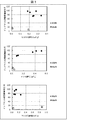
- a toxin separation device has a pore volume (mesopore volume) of a pore (referred to herein as “mesopore”) having a pore diameter measured by a nitrogen adsorption method of 1.4 to 35 nm. ) Is provided with activated carbon having 0.06 cm 3 / g or more.
- Mesopore volume is preferably 0.08 cm 3 / g or more, more preferably 0.10 cm 3 / g or more, further preferably 0.12 cm 3 / g or more. It is not an upper limit particularly limited mesopore volume, from the viewpoint of strength, preferably at 1.0 cm 3 / g or less, and more preferably less 0.80 cm 3 / g.
- the specific method of measuring the mesopore volume by the nitrogen adsorption method is as in the examples described later.
- micropore volume a pore volume of a pore having a pore diameter of 0.5 to 1.4 nm
- micropore The pore volume (macropore volume) of pores having a pore diameter of 50 to 10,000 nm (referred to herein as “macropores”) has no correlation with the adsorption rate of the toxin to be separated, and only the mesopores It has been found that there is a correlation with the adsorption rate of the toxin to be separated.
- the micropore volume refers to that measured by the carbon dioxide adsorption method
- macropore volume refers to that measured by the mercury intrusion method.
- the toxin separation device separates toxins from biological fluids by the action of activated carbon. Specifically, activated carbon selectively adsorbs the toxin out of the toxin and the protein. Therefore, the protein is left in the biological fluid.
- the adsorption rate of the protein is lower than the adsorption rate of the toxin. In one example, the adsorption rate of the protein is less than 1%, preferably 0%.
- the activated carbon preferably has a pore (macropore) surface area of 0.10 m 2 / g or more with a pore diameter of 50 to 10,000 nm measured by mercury porosimetry.
- a pore (macropore) surface area of 0.10 m 2 / g or more with a pore diameter of 50 to 10,000 nm measured by mercury porosimetry.
- the toxin adsorption rate (particularly, the initial adsorption rate) is increased.
- Macropore surface area is more preferably 0.25 m 2 / g or more, more preferably 0.40 m 2 / g or more.
- the specific method of measuring the macropore surface area by the mercury intrusion method is as in the examples described later.
- the bulk density of the activated carbon is not particularly limited, but is preferably 0.30 g / cm 3 or more and more preferably 0.40 g / cm 3 or more from the viewpoint of crushing strength. In terms of adsorption properties, it is preferably 0.70 g / cm 3 or less, more preferably 0.60 g / cm 3 or less.
- the bulk density is a value obtained by dividing the dry weight W (g) of activated carbon when the container is filled with activated carbon by the volume V (cm 3 ) of the activated carbon filled.
- the crushing strength of the activated carbon is not particularly limited, but is preferably 100 g / grain or more, and more preferably 200 g / grain or more from the viewpoint of reducing the generation of fine powder.
- the crushing strength of activated carbon can be measured according to the examples described later.
- the crushing strength of the activated carbon is not particularly limited, but is preferably 2.0 kg / mm 3 or more and more preferably 3.5 mg / mm 3 or more from the viewpoint of reducing the generation of fine powder.
- the crushing strength of activated carbon can be measured according to the below-mentioned Example.
- the shape of the activated carbon is not particularly limited, and examples thereof include a spherical shape, a fibrous shape, a powder shape, and a granulated product.
- the activated carbon is preferably spherical.
- a spherical shape since the contact area between the activated carbons is small, it is easy for the biological fluid to pass between the activated carbons. Further, since the structure has no corners, it is difficult to chip and fine powder is not easily generated, so that clogging can be reduced. Therefore, it is easy for the biological fluid to pass through and the safety is improved.
- the average particle size is not particularly limited, but is preferably 100 ⁇ m or more, more preferably 200 ⁇ m or more, and further preferably 250 ⁇ m or more from the viewpoint of pressure loss. Further, from the viewpoint of the adsorption rate, it is preferably 1500 ⁇ m or less, more preferably 800 ⁇ m or less, and even more preferably 600 ⁇ m or less.
- the average particle diameter means a particle diameter (D v50 ) at a particle size accumulation ratio of 50% in a volume-based particle size accumulation diagram.
- activated carbon produced as a lump rather than granulated with fine powder activated carbon with a binder or the like is preferable to use.
- Activated carbon can use any carbon-containing material as a carbon source.
- the carbon-containing material include synthetic resin and pitch.
- the synthetic resin any of a heat-meltable resin (thermosetting resin) and a heat-infusible resin (thermoplastic resin) can be used.
- the pitch include petroleum pitch and coal pitch.
- Activated carbon used as a plant raw material may be used, and examples include fruit shells such as wood, charcoal, rice husk, coconut husk and palm husk. From the viewpoint of a small amount of impurities, a synthetic resin or pitch is preferable.
- Activated carbon can be manufactured according to the below-mentioned Example, for example.
- the toxin separation device includes the activated carbon.
- the toxin separation device is a column.
- the amount of activated carbon in the column is not particularly limited, and may be appropriately selected depending on the type of biological fluid, the amount of biological fluid, the shape of activated carbon, and the like.
- the toxin separation device is a blood purification column, and the amount of activated carbon is preferably, for example, 50 to 500 g / column, more preferably 75 to 400 g / column, and 100 to 300 g / column. More preferably, it is a column.
- the size of the column housing is not particularly limited, and may be appropriately selected according to the purpose.
- the toxin separation device is a filter.
- the size of the filter is not particularly limited, and may be appropriately selected depending on the type of biological fluid, the amount of biological fluid, the shape of activated carbon, and the like.
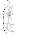
- FIG. 1 is a schematic diagram showing an example of a blood purification system 100 according to an embodiment of the present invention.
- the blood purification system 100 includes at least a toxin separation instrument 1 and a dialyzer 3.
- the toxin separation instrument 1 is a column (blood purification column) having a large number of activated carbons 2 therein.
- the toxin separation device 1 has a blood inlet 1a for allowing blood to flow in and a blood outlet 1b for discharging purified blood.
- the dialyzer 3 is an existing dialyzer (for example, a hollow fiber type dialyzer).
- the dialyzer 3 has a pore size of the porous separation membrane adjusted, and removes low molecular weight toxins such as urea and creatine by filtration and diffusion from the blood side to the dialysate side, while blood cells and platelets in the blood are removed. Proteins such as albumin and complement are prevented from passing through.
- the dialyzer 3 has a blood inlet 3a for allowing blood to flow in and a blood outlet 3b for allowing purified blood to flow out.
- the dialyzer 3 has a dialysate inlet 3c for allowing dialysate to flow in and a dialysate outlet 3d for allowing dialysate to flow out.
- the dialysate inflow port 3 c is connected to a dialysate supply unit (for example, including a dialysate supply device and a dialysis monitoring device) 16 via a tube 17.
- a tube 18 is connected to the dialysate outlet 3d.
- the dialysate flows from the dialysate supply unit 16 in the order of the tube 17, dialyzer 3, and tube 18, and the dialysate recovery unit (not shown, for example, in the dialysis monitoring device) downstream of the tube 18 It may be).
- the toxin separation device 1 is disposed on the upstream side of the dialyzer 3, and the blood outlet 1b of the toxin separation device 1 and the blood inlet 3a of the dialyzer 3 are connected by a tube 14. Therefore, the blood that has passed through the toxin separation device 1 is configured to flow into the dialyzer 3.
- a tube 13 is connected to the blood inlet 1a of the toxin separation instrument 1. Further, a pump 12 for feeding blood is connected to the tube 13. Further, a tube 11 is connected to the pump 12. The tube 11 is inserted into a blood vessel of a dialysis patient when the blood purification system 100 is used.
- a tube 15 is connected to the blood outlet 3 b of the dialyzer 3.
- the tube 15 is inserted into a blood vessel of a dialysis patient when the blood purification system 100 is used.
- the blood purification system 100 is configured by further disposing the toxin separating device 1 in front of the dialyzer 3 (upstream side) in a conventional typical hemodialysis configuration.
- the other member may be inserted in arbitrary positions.
- the blood purification system 100 is configured to include at least the toxin separation instrument 1 and the dialyzer 3, but other members (for example, the above-described members) may be optionally included in the blood purification system 100.
- the toxin separation device 1 may be disposed on the downstream side of the dialyzer 3.
- purification means that at least a part of at least one (one or more) protein-binding toxins in a biological fluid is separated from the biological fluid.
- 40% or more, preferably 70% or more, more preferably 90% or more of at least one (one or more) protein-binding toxins in the biological fluid are derived from the biological fluid. To be separated.
- a toxin separation method is a method for separating a toxin from a biological fluid, wherein the toxin is bound to a protein and is present in the biological fluid. A step of passing the biological fluid.
- FIG. 2 is a schematic diagram for explaining the separation of protein-binding toxins when the blood purification system 100 is used.
- the blood that has flowed into the toxin separation device 1 contacts the activated carbon 2 in the toxin separation device 1.
- the specific mechanism is not particularly limited, but the activated carbon 2 adsorbs the toxin 22 in the toxin-protein complex 21.
- activated carbon 2 does not adsorb protein 23.
- the removal amount of the toxin 22 existing in the blood by binding to the protein 23 is dramatically increased.
- a plurality of types of toxins 22 may be separated by the toxin separation instrument 1.
- toxins that do not bind to proteins may also be separated by the toxin separation instrument 1.
- the toxin separation method further includes a step of passing the biological fluid through a dialyzer before or after the step of passing the biological fluid through the toxin separation instrument.
- the “toxin separation method” can also be referred to as the “biological fluid purification method”.
- toxin separation device is used in vitro, and therefore the toxin separation method is performed in vitro.
- the activated carbon for toxin separation is activated carbon for separating a toxin from a biological fluid, wherein the toxin is bound to a protein and present in the biological fluid, and is adsorbed with nitrogen.
- the pore volume of pores having a pore diameter measured by the method of 1.4 to 35 nm is 0.06 cm 3 / g or more.
- the present invention also provides a dialysis method using the above-described toxin separation device or the above-described blood purification system.
- the present invention also provides a method for treating or preventing uremia using the above-described toxin separation device or the above-described blood purification system.
- the method treats or prevents uremia caused by protein-bound uremic toxins.
- the present invention also provides activated carbon having a pore diameter of 1.4 to 35 nm measured by a nitrogen adsorption method and a volume of 0.06 cm 3 / g or more.
- the present invention also provides a column packing material for packing a column for separating toxin from a biological fluid, wherein the toxin is present in the biological fluid by binding to a protein and measured by a nitrogen adsorption method.
- a column filler made of activated carbon having a pore diameter of 1.4 to 35 nm and a pore volume of 0.06 cm 3 / g or more.
- a particle size cumulative diagram was prepared according to JIS K 1474.
- the horizontal line is drawn on the horizontal axis from the intersection of the vertical line at the 50% point on the horizontal axis and the particle size cumulative line to obtain the mesh size (mm) of the sieve indicated by the intersection.
- the average particle size was used.
- the bulk density After filling the graduated cylinder with activated carbon, tapping was repeated until the bulk did not change. The bulk density was calculated by dividing the dry weight W (g) of the activated carbon at this time by the volume V (cm 3 ) of the activated carbon.
- crushing strength was calculated by dividing the crushing strength by the volume calculated from the average particle diameter.
- the specific surface area Based on the method defined in JIS Z 8830, the specific surface area (SSA) was measured. That is, the specific surface area can be calculated by the following equation by measuring the gas adsorption amount of activated carbon using a specific surface area measuring instrument (for example, “ASAP2010” manufactured by MICROMERITICS) by a gas adsorption method. Specifically, activated carbon as a sample was filled in a sample tube, dried under reduced pressure at 300 ° C., and the weight of the sample after drying was measured.
- a specific surface area measuring instrument for example, “ASAP2010” manufactured by MICROMERITICS
- the sample tube was cooled to ⁇ 196 ° C., nitrogen was introduced into the sample tube, nitrogen was adsorbed on the spherical activated carbon sample, and the relationship between nitrogen partial pressure and adsorption amount (adsorption isotherm) was measured.
- MA is the cross-sectional area of the nitrogen molecule, and 0.162 nm 2 was substituted.
- [Micropore volume] Measurement was carried out using “Autosorb (registered trademark) -iQ” manufactured by Cantachrome Instruments. First, a sample was filled in a sample tube and dried under reduced pressure at 200 ° C. for 12 hours to perform a pretreatment for removing impurities such as moisture in pores in the sample. Next, the sample temperature was lowered to ⁇ 78 ° C. using dry ice ethanol while reducing the pressure. Here, it introduce
- NLDFT delocalized density functional method
- [Mesopore volume] The pore volume was measured using “Autosorb (registered trademark) -iQ” manufactured by Cantachrome Instruments. First, a sample was filled in a sample tube and dried under reduced pressure at 200 ° C. for 12 hours to perform a pretreatment for removing impurities such as moisture in pores in the sample. Next, the sample temperature was lowered to -196 ° C. using liquid nitrogen while reducing the pressure. Here, it introduced in steps, changing the pressure of nitrogen, and the amount of nitrogen adsorption of the sample at each pressure was measured. From the relationship between the obtained pressure and the amount of nitrogen adsorbed, the volume (cm 3 / g) of pores having a pore diameter of 1.5 to 35 nm was measured using the Barrett Joyner Hallenda method.
- a mercury porosimeter for example, “AUTOPOREIV 9500” manufactured by MICROMERITICS.
- the volume of mercury injected into the sample from a pressure (0.01 MPa) corresponding to a pore diameter of 89 ⁇ m to a maximum pressure (414 MPa: equivalent to a pore diameter of 3 nm) was measured.
- the surface tension of mercury is 484 dyne / cm
- the contact angle between mercury and carbon is 130 degrees
- the pressure P is MPa
- the relationship between the pressure P and the pore diameter D was determined.
- the pore volume having a pore diameter in the range of 50 nm to 300 nm in the present invention corresponds to the volume V of mercury injected from a mercury intrusion pressure of 4.2 MPa to 25.4 MPa.
- a container for example, “Mobicol Polypropylene Column” manufactured by Mobitech Co., Ltd.
- the membrane filter after the filtration treatment was dried at 110 ° C. for 1 hour, then allowed to cool in a desiccator for 30 minutes, and weighed to 0.1 mg with a precision chemical balance.
- Indoxyl sulfate adsorption rate (%) (C 0 -C) / C 0 ⁇ 100
- C 0 Indoxyl sulfate initial concentration before treatment
- C Indoxyl sulfate residual concentration after treatment
- Indoxyl sulfate initial concentration before treatment C 0 is obtained by adding 0.1 mL of physiological saline to a round bottom tube made of polypropylene (PP). After mixing, 0.9 mL of the test solution was added and immediately centrifuged at 3000 g for 10 minutes using a centrifuge, and the supernatant was obtained as a pre-treatment plasma sample. The indoxyl sulfate concentration in the bovine blood at this time was 3.5 to 3.8 mg / dL.
- the initial albumin concentration and the residual concentration were measured using a biochemical automatic analyzer (for example, “Unicel DxC600 Clinical System” manufactured by Beckman Coulter, Inc.), and the albumin adsorption rate was calculated using the above-described adsorption rate calculation formula. Calculated.
- the initial adsorption rate of indoxyl sulfate was calculated by dividing the amount of adsorbed indoxyl sulfate after 5 minutes by time (5 minutes).
- Adsorption test 2 immersion method
- adsorption experiments of indole-3-acetic acid, phenylsulfuric acid, p-cresylsulfuric acid, and hippuric acid were performed by the following method.
- a plasma sample after treatment was obtained in the same manner as in adsorption test 1 except that a 5-component mixed solution obtained by adding the above-mentioned 4 components was added instead of adding an aqueous solution of indoxyl sulfate.
- the adsorption rate was calculated in the same manner as indoxyl sulfate.
- a mini-module was manufactured by filling 200 mg of the activated carbon sample into a container (for example, “Mobicol Polypropylene Column” manufactured by Mobitech Co., Ltd.) having an inlet for inflow and an outlet for outflow.
- An aqueous solution of indoxyl sulfate (potassium salt, manufactured by Sigma-Aldrich) prepared to 5 mg / mL was added to bovine blood anticoagulated by addition of heparin (10 U / mL) to prepare a test solution.
- test solution was passed through the minimodule using a peristaltic pump, the test solution flowing out from the outlet was collected 30 minutes later, centrifuged at 3000 g for 10 minutes using a centrifuge, and the supernatant was obtained as a plasma sample after processing.
- the indoxyl sulfate adsorption rate was calculated in the same manner as in adsorption test 1.
- Example 1 A 70 kg petroleum pitch with a softening point of 205 ° C. and an H / C atomic ratio of 0.65 and 30 kg of naphthalene are charged into a 300 liter pressure vessel equipped with a stirring blade and an outlet nozzle, and heated, melted and mixed at 190 ° C. After cooling to 80 to 90 ° C., the inside of the pressure vessel was pressurized with nitrogen gas, and the contents were extruded from the outlet nozzle to obtain a string-like molded body having a diameter of about 500 ⁇ m.
- this string-like molded body was pulverized so that the ratio (L / D) of the diameter (D) to the length (L) was about 1.5, and the obtained crushed material was heated to 93 ° C.
- the solution was poured into an aqueous solution in which 53% by mass of polyvinyl alcohol (saponification degree 88%) was dissolved, stirred and dispersed, and cooled to obtain a spherical pitch molded body slurry. After most of the water was removed by filtration, naphthalene in the pitch formed body was extracted and removed with n-hexane having a mass about 6 times that of the spherical pitch formed body.
- the porous spherical pitch obtained in this manner was heated to 260 ° C. while passing through heated air using a fluidized bed, oxidized at a temperature of 260 ° C. for 2 hours, and insoluble to heat. Spherical oxidized pitch was obtained.
- a porous spherical oxidation pitch is put in a vertical tubular furnace having a diameter of 50 mm, heated to 200 ° C./h up to 850 ° C. under nitrogen gas flow, held at 850 ° C. for 1 hour, and pre-baked.
- a carbon precursor was obtained.
- the obtained carbon precursor was subjected to activation treatment at 850 ° C. in a nitrogen gas containing 50 vol% of water vapor until the bulk density became 0.46 g / cm 3 to obtain spherical activated carbon 1.
- Example 2 A porous spherical pitch similar to that in Example 1 was heated to 240 ° C. while passing through heated air using a fluidized bed, and maintained at 240 ° C. for 2 hours to oxidize and porous infusible to heat. Spherical oxidized pitch was obtained. Next, 40 g of porous spherical oxidation pitch is put in a tubular furnace, heated to 1350 ° C. at 250 ° C./h under a nitrogen gas flow, and kept at 1350 ° C. for 4 hours to carry out preliminary firing to obtain a carbon precursor. It was. Next, the obtained carbon precursor was subjected to activation treatment at 900 ° C. in a nitrogen gas containing 50 vol% of water vapor until the bulk density became 0.47 g / cm 3 to obtain spherical activated carbon 2.
- Example 3 Spherical activated carbon 3 was obtained in the same manner as in Example 1 except that the activation treatment was performed until the bulk density reached 0.60 g / cm 3 .
- Example 4 A porous spherical pitch similar to that in Example 1 was heated to 210 ° C. while passing through heated air using a fluidized bed, oxidized at a temperature of 210 ° C. for 2 hours, and insoluble to heat. Spherical oxidized pitch was obtained. 100 g was put into a vertical tubular furnace having a diameter of 50 mm, heated to 200 ° C./h up to 850 ° C. under a nitrogen gas flow, and kept at 850 ° C. for 1 hour to perform preliminary firing to obtain a carbon precursor. Next, the obtained carbon precursor was subjected to activation treatment at 850 ° C. in nitrogen gas containing 50 vol% of water vapor until the bulk density became 0.60 g / cm 3 to obtain spherical activated carbon 4.
- Example 5 40 g of porous spherical oxidation pitch similar to that in Example 4 was put in a tubular furnace, heated to 1200 ° C. at 250 ° C./h under nitrogen gas flow, held at 1200 ° C. for 4 hours, pre-fired, and carbon A precursor was obtained. Next, the obtained carbon precursor was subjected to activation treatment at 900 ° C. in a nitrogen gas containing 50 vol% of water vapor until the bulk density became 0.45 g / cm 3 to obtain spherical activated carbon 5.
- Example 6 Spherical white birch (manufactured by Osaka Gas Chemical Company) was used as the activated carbon.
- this activated carbon is not manufactured as a lump, but is obtained by granulating finely powdered activated carbon with a binder.
- Example 7 Petroleum pitch and SiO 2 were homogeneously mixed with each other at a weight ratio of 25:75, stirred while heating at 300 ° C., and then cooled to room temperature to prepare a composite pitch material in which SiO 2 was dispersed.
- the obtained composite pitch was roughly pulverized with a hammer mill and then pulverized with a jet mill (Hosokawa Micron Corporation / 100-AFG) to obtain a finely pulverized composite pitch.
- the finely pulverized composite pitch was heated to an air atmosphere of 260 ° C. and held at 260 ° C. for 1 hour to perform an infusibilization treatment.
- the obtained infusible finely pulverized composite pitch was held at 650 ° C. for 1 hour, and then treated with a hydrofluoric acid aqueous solution to remove SiO 2 to obtain a porous carbon material. After putting 30 g of this porous carbon material in a crucible and holding it at 850 ° C. for 1 hour under a nitrogen gas flow in a vertical tubular furnace, the bulk density becomes 0.16 g / cm 3 in nitrogen gas containing 50 vol% of water vapor. Until then, activation treatment was performed at 850 ° C., and powdered activated carbon 1 was obtained.
- Example 8 Powdered activated carbon 2 was obtained in the same manner as in Example 7 except that the activation treatment was performed until the bulk density became 0.20 g / cm 3 .
- Example 9 30 g of a phenol resin (Asahi Organic Material: BEAPS) was put in a crucible, and pre-baked by holding at 850 ° C. for 1 hour under a nitrogen gas flow in a vertical tubular furnace to obtain a carbon precursor. Next, the obtained carbon precursor was subjected to activation treatment at 850 ° C. in nitrogen gas containing 50 vol% of water vapor until the bulk density became 0.51 g / cm 3 to obtain spherical activated carbon 8.
- a phenol resin Asahi Organic Material: BEAPS
- Example 10 In place of the spherical activated carbon, activated carbon fiber (Soene Co.) was used.
- Example 11 220 g of deionized water and 58 g of methylcellulose were placed in a 1 L separable flask, and 105 g of styrene, 57% divinylbenzene (57% divinylbenzene and 43% ethylvinylbenzene) 184 g, 2,2'-azobis 2.68 g of 2,4-dimethylvaleronitrile) and 63 g of 1-butanol as a porogen were appropriately added. Next, the inside of the system was replaced with nitrogen gas, and this two-phase system was stirred at 150 rpm, heated to 55 ° C., and held for 20 hours.
- the obtained resin was filtered and dried on a rotary evaporator, and then 1-butanol was removed from the resin by distillation in a vacuum dryer, and then dried at 90 ° C. for 12 hours, and spherical porous particles having an average particle size of 180 ⁇ m.
- a synthetic resin was obtained. 100 g of the obtained spherical porous synthetic resin was charged into a reaction tube with a mesh dish and subjected to infusibilization treatment in a vertical tubular furnace.
- the infusibilization condition is that a spherical porous oxide resin is obtained by flowing dry air from the lower part of the reaction tube to the upper part at 3 L / min, raising the temperature to 260 ° C.
- the bulk density is 0.50 g / cm 3 at 820 ° C. in a nitrogen gas atmosphere containing 64.5 vol% of water vapor using a fluidized bed.
- the activation treatment was performed until the spherical activated carbon 9 was obtained.
- Powdered activated carbon 3 was obtained in the same manner as in Example 7 except that the activation treatment was not performed.
- Example 8 having a large macropore surface area had a higher adsorption rate (initial adsorption rate).
- indole-3-acetic acid, phenylsulfuric acid, p-cresylsulfuric acid, and hippuric acid also showed the same adsorption as indoxylsulfuric acid.
- the same results as in the case of indoxyl sulfate were obtained.
- the albumin adsorption rate was 0% in experiments using indole-3-acetic acid, phenylsulfuric acid, p-cresylsulfuric acid, and hippuric acid.
- Table 4 shows the results of the liquid passing method. Here, the result after 30 minutes of Example 1 is shown as a representative.
- the present invention can be used for hemodialysis and the like.
Landscapes
- Chemical & Material Sciences (AREA)
- Health & Medical Sciences (AREA)
- Analytical Chemistry (AREA)
- Chemical Kinetics & Catalysis (AREA)
- Organic Chemistry (AREA)
- Engineering & Computer Science (AREA)
- Heart & Thoracic Surgery (AREA)
- Vascular Medicine (AREA)
- Nanotechnology (AREA)
- Life Sciences & Earth Sciences (AREA)
- Biomedical Technology (AREA)
- Anesthesiology (AREA)
- General Health & Medical Sciences (AREA)
- Veterinary Medicine (AREA)
- Public Health (AREA)
- Hematology (AREA)
- Animal Behavior & Ethology (AREA)
- Cardiology (AREA)
- Inorganic Chemistry (AREA)
- Biodiversity & Conservation Biology (AREA)
- Cell Biology (AREA)
- Molecular Biology (AREA)
- External Artificial Organs (AREA)
- Solid-Sorbent Or Filter-Aiding Compositions (AREA)
- Treatment Of Liquids With Adsorbents In General (AREA)
- Carbon And Carbon Compounds (AREA)
- Medicines Containing Antibodies Or Antigens For Use As Internal Diagnostic Agents (AREA)
- Medicines Containing Material From Animals Or Micro-Organisms (AREA)
- Medicines That Contain Protein Lipid Enzymes And Other Medicines (AREA)
Abstract
Provided is a toxin separator or the like that is to be used for a toxin bound to a protein and present in an organism-derived liquid and that is capable of selectively separating the toxin from between the toxin and the protein. The toxin separator according to the present invention includes an activated charcoal in which the volume of pores, of which the diameters measured by a nitrogen adsorption method are 1.4-35 nm, is not less than 0.06 cm3/g.
Description
本発明は、生体由来液から毒素を分離する毒素分離器具等に関する。
The present invention relates to a toxin separation instrument for separating toxin from a biological fluid.
腎疾患患者などの血液中に含まれる毒素を除去する目的で、患者の体外に血液循環路を形成し、患者の血液を体内から体外へ取り出し、体外での浄化処理を実施してから、再び患者体内へ血液を戻す治療方法が行われている。このような血液浄化の代表的手段として、従来から、ポリスルホン製透析膜等の多孔質分離膜が利用されてきた。具体的な例として、ポリスルホン製の中空糸膜(多孔質分離膜)をハウジングに充填した中空糸型ダイアライザーが挙げられる。一般的な中空糸型ダイアライザーでは、中空糸の内側に血液を流し、中空糸の外側に透析液を流す。従来の多孔質分離膜は、細孔径が調整されており、血液側から透析液側への濾過および拡散によって、尿素およびクレアチンなどの低分子量の毒素を除去する一方、血液中の血球、血小板、アルブミンおよび補体などの有用なタンパク質は通過しないようになっている。そのため、比較的分子量の大きい溶質は、血液から除去することが困難である。
For the purpose of removing toxins contained in the blood of patients with kidney disease, etc., a blood circulation path is formed outside the patient's body, the patient's blood is taken out of the body, and the purification process outside the body is performed, and then again. Treatment methods have been used to return blood to the patient. As a representative means for such blood purification, a porous separation membrane such as a polysulfone dialysis membrane has been conventionally used. A specific example is a hollow fiber dialyzer in which a housing is filled with a polysulfone hollow fiber membrane (porous separation membrane). In a general hollow fiber type dialyzer, blood is allowed to flow inside the hollow fiber and dialysate is allowed to flow outside the hollow fiber. The conventional porous separation membrane has a controlled pore size, and removes low molecular weight toxins such as urea and creatine by filtration and diffusion from the blood side to the dialysate side, while blood cells, platelets, Useful proteins such as albumin and complement are prevented from passing. Therefore, it is difficult to remove a solute having a relatively large molecular weight from blood.
そこで、比較的分子量の大きい毒素を除去するために、活性炭を用いる方法が知られている。例えば、特許文献1には、直径が0.1~1mmであり、H/Cが0.14以下であり、そして細孔直径5~1000nmの細孔の細孔容積が0.25~0.55mL/gである、血液の直接灌流用球状活性炭が記載されている。この直接灌流用球状活性炭は、分子量約100~1000の毒性物質に対する吸着能は従来の球状活性炭と少なくとも同程度であるが、分子量約1000~10000の毒性物質に対する吸着能が従来の球状活性炭よりも向上することが記載されている。
Therefore, a method using activated carbon is known to remove toxins having a relatively large molecular weight. For example, in Patent Document 1, the diameter is 0.1 to 1 mm, H / C is 0.14 or less, and the pore volume of pores having a pore diameter of 5 to 1000 nm is 0.25 to 0.00. A spherical activated carbon for direct perfusion of blood, which is 55 mL / g, is described. This spherical activated carbon for direct perfusion has an adsorption capacity for toxic substances having a molecular weight of about 100 to 1000, which is at least the same as that of conventional spherical activated carbon, but has an adsorption capacity for toxic substances having a molecular weight of about 1000 to 10,000, compared to conventional spherical activated carbon. It is described that it improves.
一方、血液中には、タンパク質と結合している毒素も存在する。例えば、毒素であるインドキシル硫酸は、腎疾患患者の血液中ではアルブミン(分子量約66000)と結合して顕著に蓄積していることが知られている。さらに、インドキシル硫酸が腎疾患患者(特に血液透析患者)の種々の病態(掻痒感および心血管疾患など)に関与していることも報告されている。しかしながら、これらのタンパク質と結合している毒素は、従来の多孔質分離膜を用いた透析では、ほとんど除去することができない。そこでインドキシル硫酸の蓄積を低減するための解決法として、球状活性炭を含む経口吸着剤を用いて、インドキシル硫酸の前駆体であるインドールを消化管内で吸着し、インドキシル硫酸の生成を抑制する方法がある。例えば、特許文献2には、インドールを大量に吸着することができる経口投与用吸着剤として、(細孔直径3nm未満の細孔の細孔容積)/(細孔直径3~50nmの細孔の細孔容積)が3.0以上である球状活性炭を含む経口投与用吸着剤が記載されている。
On the other hand, there are toxins bound to proteins in blood. For example, it is known that indoxyl sulfate, which is a toxin, is significantly accumulated by binding to albumin (molecular weight of about 66000) in the blood of patients with renal diseases. Furthermore, it has been reported that indoxyl sulfate is involved in various pathological conditions (pruritus and cardiovascular disease, etc.) of renal disease patients (particularly hemodialysis patients). However, toxins bound to these proteins can hardly be removed by dialysis using a conventional porous separation membrane. Therefore, as a solution to reduce the accumulation of indoxyl sulfate, indole, the precursor of indoxyl sulfate, is adsorbed in the digestive tract using an oral adsorbent containing spherical activated carbon, and the production of indoxyl sulfate is suppressed. There is a way. For example, in Patent Document 2, as an adsorbent for oral administration capable of adsorbing a large amount of indole, (pore volume of pore having a pore diameter of less than 3 nm) / (pore diameter of 3 to 50 nm). An adsorbent for oral administration containing spherical activated carbon having a pore volume) of 3.0 or more is described.
しかしながら、特許文献1では、タンパク質と結合している毒素は吸着対象として言及されてはいない。また、特許文献1に記載の球状活性炭では、毒素だけでなく当該タンパク質も除去される虞がある。
However, Patent Document 1 does not mention a toxin bound to a protein as an adsorption target. Moreover, in the spherical activated carbon described in Patent Document 1, not only the toxin but also the protein may be removed.
特許文献2に記載されているような球状活性炭を含む経口吸着剤では、既に血液中に存在しているインドキシル硫酸等の毒素を直接吸着することにより低減させることはできない。また、実質的には透析患者での使用は適応外であり、血液透析への導入を遅らせることを目的として、保存期慢性腎不全患者での使用に限られているのが現状である。
An oral adsorbent containing spherical activated carbon as described in Patent Document 2 cannot be reduced by directly adsorbing toxins such as indoxyl sulfate already present in blood. In addition, the use in dialysis patients is practically off-label, and the current situation is limited to use in patients with chronic renal failure in conservative phase for the purpose of delaying introduction into hemodialysis.
したがって、本発明の一実施形態の目的は、タンパク質と結合して生体由来液中に存在している毒素について、当該毒素と当該タンパク質とのうち当該毒素を選択的に分離することができる毒素分離器具等を提供することである。
Therefore, an object of one embodiment of the present invention is to isolate a toxin that can selectively separate the toxin from the toxin and the protein with respect to the toxin that is bound to the protein and present in the biological fluid. It is to provide equipment.
前記の課題を解決するために、本発明の一実施形態に係る毒素分離器具は、生体由来液から毒素を分離する毒素分離器具であって、前記毒素はタンパク質と結合して前記生体由来液中に存在しており、窒素吸着法によって測定した細孔直径が1.4~35nmの細孔の細孔容積が0.06cm3/g以上である活性炭を備える。
In order to solve the above-described problem, a toxin separation device according to an embodiment of the present invention is a toxin separation device that separates a toxin from a biological fluid, and the toxin binds to a protein in the biological fluid. And activated carbon having a pore diameter of 1.4 to 35 nm measured by a nitrogen adsorption method and having a pore volume of 0.06 cm 3 / g or more.
本発明の一実施形態はまた、前記毒素分離器具と、ダイアライザーとを備える、血液浄化システムを提供する。
One embodiment of the present invention also provides a blood purification system comprising the toxin separating instrument and a dialyzer.
本発明の一実施形態はまた、生体由来液から毒素を分離する方法であって、前記毒素はタンパク質と結合して前記生体由来液中に存在しており、前記毒素分離器具に前記生体由来液を通液する工程を含む、毒素分離方法を提供する。
One embodiment of the present invention is also a method for separating a toxin from a biological fluid, wherein the toxin is bound to a protein and is present in the biological fluid, and the biological fluid is attached to the toxin separation instrument. There is provided a method for separating toxins, comprising a step of passing through.
本発明の一実施形態はまた、生体由来液から毒素を分離するための活性炭であって、前記毒素はタンパク質と結合して前記生体由来液中に存在しており、窒素吸着法によって測定した細孔直径が1.4~35nmの細孔の細孔容積が0.06cm3/g以上である、毒素分離用活性炭を提供する。
One embodiment of the present invention is also activated carbon for separating toxin from biological fluid, wherein the toxin is bound to protein and present in the biological fluid, and is measured by a nitrogen adsorption method. Provided is an activated carbon for toxin separation, wherein the pore volume of pores having a pore diameter of 1.4 to 35 nm is 0.06 cm 3 / g or more.
本発明の一実施形態によれば、タンパク質と結合して生体由来液中に存在している毒素について、当該毒素と当該タンパク質とのうち当該毒素を選択的に分離することができる。したがって、有用なタンパク質を生体由来液中に残したまま、有害な毒性を効率的に生体由来液中から除去することができる。
According to one embodiment of the present invention, the toxin can be selectively separated from the toxin and the protein with respect to the toxin bound to the protein and present in the biological fluid. Therefore, harmful toxicity can be efficiently removed from the biological fluid while the useful protein remains in the biological fluid.
以下、本発明の一実施形態について説明する。なお、本明細書において「~」とはその前後に記載される数値を下限値および上限値として含む意味で使用される。
〔1.毒素分離器具〕
本発明の一実施形態に係る毒素分離器具は、生体由来液から毒素を分離する毒素分離器具であって、前記毒素はタンパク質と結合して前記生体由来液中に存在しており、窒素吸着法によって測定した細孔直径が1.4~35nmの細孔の細孔容積が0.06cm3/g以上である活性炭を備える。 Hereinafter, an embodiment of the present invention will be described. In the present specification, “˜” is used to mean that the numerical values described before and after it are included as a lower limit value and an upper limit value.
[1. Toxin separator
A toxin separation device according to an embodiment of the present invention is a toxin separation device for separating a toxin from a biological fluid, wherein the toxin is bound to a protein and present in the biological fluid, and a nitrogen adsorption method. Activated carbon having a pore diameter of 1.4 to 35 nm measured by the above and having a pore volume of 0.06 cm 3 / g or more.
(生体由来液)
本明細書において、生体由来液とは、生体から取得された液体を指す。生体由来液としては、血液、血漿、血清、尿および腹水等の体液、ならびに細胞培養液等が挙げられる。生体由来液は、未処理であってもよいし、任意の処理が施されていてもよい。一例において、生体由来液は、血液透析を必要とする患者から取得された血液である。由来生物は特に限定されず、哺乳類、鳥類、および爬虫類等が挙げられ、好ましくは、イヌおよびネコ等のペット;ウシ、ウマおよびブタ等の家畜;ならびにヒト等を含む哺乳類である。 (Biological fluid)
In this specification, the biological fluid refers to a liquid obtained from a biological body. Examples of the biological fluid include body fluids such as blood, plasma, serum, urine and ascites, and cell culture fluid. The biological fluid may be untreated or may be subjected to any treatment. In one example, the biological fluid is blood obtained from a patient in need of hemodialysis. The origin organism is not particularly limited, and includes mammals, birds, reptiles, etc., preferably pets such as dogs and cats; domestic animals such as cows, horses and pigs; and mammals including humans.
(毒素)
本発明の一実施形態に係る毒素分離器具によって分離される毒素は、タンパク質と結合して生体由来液中に存在している毒素(タンパク質結合性毒素(protein-bound toxin))である。そのような毒素としては、尿毒症毒素が挙げられる。タンパク質結合性の尿毒症毒素としては、インドキシル硫酸、3-カルボキシ-4-メチル-5-プロピル-2-フランプロピオン酸(CMPF)、馬尿酸、ホモシステイン、インドール-3-酢酸、N-カルボキシメチルリジン、p-クレジル硫酸、ペントシジン、フェニル硫酸、キノリン酸、スペルミジン、およびグリオキサール等の低分子(分子量500未満)の尿毒症毒素が挙げられる。一例において、毒素の分子量は、58以上500未満であり得る。 (toxin)
The toxin separated by the toxin separation device according to an embodiment of the present invention is a toxin (protein-bound toxin) that is bound to a protein and is present in a biological fluid. Such toxins include uremic toxins. Protein binding uremic toxins include indoxyl sulfate, 3-carboxy-4-methyl-5-propyl-2-furanpropionic acid (CMPF), hippuric acid, homocysteine, indole-3-acetic acid, N-carboxyl Examples include uremic toxins of low molecular weight (less than 500 molecular weight) such as methyl lysine, p-cresyl sulfate, pentosidine, phenyl sulfate, quinolinic acid, spermidine, and glyoxal. In one example, the molecular weight of the toxin can be greater than or equal to 58 and less than 500.
なお、毒素は、生体由来液中で、100%がタンパク質と結合している必要はなく、少なくとも一部(例えば、10%以上、20%以上、30%以上、40%以上、50%以上、60%以上、70%以上、80%以上、90%以上、95%以上、または99%以上)が結合しているものであってもよい。
The toxin does not need to be 100% bound to the protein in the biological fluid, and at least a part (for example, 10% or more, 20% or more, 30% or more, 40% or more, 50% or more, 60% or more, 70% or more, 80% or more, 90% or more, 95% or more, or 99% or more) may be bonded.
毒素が結合するタンパク質としては、アルブミン、およびα1-酸性糖たんぱく質等が挙げられる。一例において、当該タンパク質は、生体にとって有用なタンパク質である。タンパク質の分子量は、例えば、10000以上、30000以上、または60000以上であり得る。
Proteins to which the toxin binds include albumin and α1-acid glycoprotein. In one example, the protein is a protein useful for a living body. The molecular weight of the protein can be, for example, 10,000 or more, 30000 or more, or 60000 or more.
一実施形態に係る毒素分離器具は、1種類または複数種類のタンパク質結合性毒素について、当該毒素を生体由来液から分離する。
The toxin separation device according to one embodiment separates the toxin from a biological fluid for one or more types of protein-binding toxins.
(活性炭)
本発明の一実施形態に係る毒素分離器具は、窒素吸着法によって測定した細孔直径が1.4~35nmの細孔(本明細書では「メソ孔」という)の細孔容積(メソ孔容積)が0.06cm3/g以上である活性炭を備える。メソ孔容積は、0.08cm3/g以上であることが好ましく、0.10cm3/g以上であることがより好ましく、0.12cm3/g以上であることがさらに好ましい。メソ孔容積の上限は特に限定されないが、強度の観点からは、1.0cm3/g以下であることが好ましく、0.80cm3/g以下であることがより好ましい。窒素吸着法によるメソ孔容積の測定の具体的な方法は、後述の実施例のとおりである。 (Activated carbon)
A toxin separation device according to an embodiment of the present invention has a pore volume (mesopore volume) of a pore (referred to herein as “mesopore”) having a pore diameter measured by a nitrogen adsorption method of 1.4 to 35 nm. ) Is provided with activated carbon having 0.06 cm 3 / g or more. Mesopore volume is preferably 0.08 cm 3 / g or more, more preferably 0.10 cm 3 / g or more, further preferably 0.12 cm 3 / g or more. It is not an upper limit particularly limited mesopore volume, from the viewpoint of strength, preferably at 1.0 cm 3 / g or less, and more preferably less 0.80 cm 3 / g. The specific method of measuring the mesopore volume by the nitrogen adsorption method is as in the examples described later.
本願発明者らは、後述の実施例で示されるように、細孔直径が0.5~1.4nmの細孔(本明細書では「ミクロ孔」という)の細孔容積(ミクロ孔容積)および細孔直径が50~10000nmの細孔(本明細書では「マクロ孔」という)の細孔容積(マクロ孔容積)は、分離対象である毒素の吸着率と相関がなく、メソ孔のみが分離対象である毒素の吸着率と相関していることを見出している。なお、本明細書において、ミクロ孔容積は、二酸化炭素吸着法によって測定したものを指し、マクロ孔容積は、水銀圧入法によって測定したものを指す。これらの具体的な方法は、後述の実施例のとおりである。
The inventors of the present application, as shown in Examples below, have a pore volume (micropore volume) of a pore having a pore diameter of 0.5 to 1.4 nm (referred to herein as “micropore”). The pore volume (macropore volume) of pores having a pore diameter of 50 to 10,000 nm (referred to herein as “macropores”) has no correlation with the adsorption rate of the toxin to be separated, and only the mesopores It has been found that there is a correlation with the adsorption rate of the toxin to be separated. In the present specification, the micropore volume refers to that measured by the carbon dioxide adsorption method, and the macropore volume refers to that measured by the mercury intrusion method. These specific methods are as in Examples described later.
本実施形態に係る毒素分離器具は、活性炭の働きによって、生体由来液から毒素を分離する。具体的には、活性炭が、前記毒素と前記タンパク質とのうち毒素を選択的に吸着する。したがって、タンパク質は、生体由来液に残される。前記タンパク質の吸着率は、前記毒素の吸着率よりも低く、一例において、前記タンパク質の吸着率は、1%未満であり、好ましくは0%である。
The toxin separation device according to this embodiment separates toxins from biological fluids by the action of activated carbon. Specifically, activated carbon selectively adsorbs the toxin out of the toxin and the protein. Therefore, the protein is left in the biological fluid. The adsorption rate of the protein is lower than the adsorption rate of the toxin. In one example, the adsorption rate of the protein is less than 1%, preferably 0%.
活性炭は、水銀圧入法によって測定した細孔直径が50~10000nmの細孔(マクロ孔)表面積が0.10m2/g以上であることが好ましい。この場合、毒素の吸着速度(特には、初期吸着速度)が速くなる。マクロ孔表面積は、0.25m2/g以上であることがより好ましく、0.40m2/g以上であることがさらに好ましい。水銀圧入法によるマクロ孔表面積の測定の具体的な方法は、後述の実施例のとおりである。
The activated carbon preferably has a pore (macropore) surface area of 0.10 m 2 / g or more with a pore diameter of 50 to 10,000 nm measured by mercury porosimetry. In this case, the toxin adsorption rate (particularly, the initial adsorption rate) is increased. Macropore surface area is more preferably 0.25 m 2 / g or more, more preferably 0.40 m 2 / g or more. The specific method of measuring the macropore surface area by the mercury intrusion method is as in the examples described later.
活性炭の嵩密度は、特に限定されないが、圧壊強力の観点で、0.30g/cm3以上であることが好ましく、0.40g/cm3以上であることがより好ましい。吸着特性の観点で、0.70g/cm3以下であることが好ましく、0.60g/cm3以下であることがより好ましい。なお、本明細書において、嵩密度は、容器に活性炭を充填したときの活性炭の乾燥重量W(g)を充填された活性炭の体積V(cm3)で除した値である。
The bulk density of the activated carbon is not particularly limited, but is preferably 0.30 g / cm 3 or more and more preferably 0.40 g / cm 3 or more from the viewpoint of crushing strength. In terms of adsorption properties, it is preferably 0.70 g / cm 3 or less, more preferably 0.60 g / cm 3 or less. In the present specification, the bulk density is a value obtained by dividing the dry weight W (g) of activated carbon when the container is filled with activated carbon by the volume V (cm 3 ) of the activated carbon filled.
活性炭の圧壊強力は、特に限定されないが、微粉の発生を低減する観点から、100g/粒以上であることが好ましく、200g/粒以上であることがより好ましい。本明細書において、活性炭の圧壊強力は、後述の実施例に従い測定することができる。
The crushing strength of the activated carbon is not particularly limited, but is preferably 100 g / grain or more, and more preferably 200 g / grain or more from the viewpoint of reducing the generation of fine powder. In this specification, the crushing strength of activated carbon can be measured according to the examples described later.
活性炭の圧壊強度は、特に限定されないが、微粉の発生を低減する観点から、2.0kg/mm3以上であることが好ましく、3.5mg/mm3以上であることがより好ましい。本明細書において、活性炭の圧壊強度は、後述の実施例に従い測定することができる。
The crushing strength of the activated carbon is not particularly limited, but is preferably 2.0 kg / mm 3 or more and more preferably 3.5 mg / mm 3 or more from the viewpoint of reducing the generation of fine powder. In this specification, the crushing strength of activated carbon can be measured according to the below-mentioned Example.
活性炭の形状は特に限定されず、例えば、球状、繊維状、粉末状、および造粒物等が挙げられる。活性炭の形状は、球状であることが好ましい。球状である場合、活性炭どうしの接触面積が小さいため、生体由来液が活性炭の間を通りやすい。また、角のない構造であるため欠けにくく、微粉が発生しにくいので、詰まりを低減することができる。そのため、生体由来液が通りやすく、また、安全性も高まる。
The shape of the activated carbon is not particularly limited, and examples thereof include a spherical shape, a fibrous shape, a powder shape, and a granulated product. The activated carbon is preferably spherical. In the case of a spherical shape, since the contact area between the activated carbons is small, it is easy for the biological fluid to pass between the activated carbons. Further, since the structure has no corners, it is difficult to chip and fine powder is not easily generated, so that clogging can be reduced. Therefore, it is easy for the biological fluid to pass through and the safety is improved.
活性炭が球状である場合、平均粒子径は特に限定されないが、圧力損失の観点から、100μm以上であることが好ましく、200μm以上であることがより好ましく、250μm以上であることがさらに好ましい。また、吸着速度の観点から、1500μm以下であることが好ましく、800μm以下であることがより好ましく、600μm以下であることがさらに好ましい。本明細書において平均粒子径とは、体積基準の粒度累積線図において粒度累積率50%における粒子径(Dv50)をいう。
When the activated carbon is spherical, the average particle size is not particularly limited, but is preferably 100 μm or more, more preferably 200 μm or more, and further preferably 250 μm or more from the viewpoint of pressure loss. Further, from the viewpoint of the adsorption rate, it is preferably 1500 μm or less, more preferably 800 μm or less, and even more preferably 600 μm or less. In the present specification, the average particle diameter means a particle diameter (D v50 ) at a particle size accumulation ratio of 50% in a volume-based particle size accumulation diagram.
活性炭は、微粉の発生を抑えて安全性を確保する観点から、微粉状の活性炭を結着剤等で造粒させたものではなく、一塊りとして製造されたものを用いることが好ましい。
From the viewpoint of ensuring the safety by suppressing the generation of fine powder, it is preferable to use activated carbon produced as a lump rather than granulated with fine powder activated carbon with a binder or the like.
活性炭は、炭素源として、任意の炭素含有材料を用いることができる。炭素含有材料としては、例えば、合成樹脂またはピッチ等が挙げられる。合成樹脂としては、熱溶融性樹脂(熱硬化性樹脂)および熱不融性樹脂(熱可塑性樹脂)のいずれも用いることができる。ピッチとしては、石油ピッチおよび石炭ピッチが挙げられる。また、植物の原料とする活性炭を用いてもよく、木材、木炭、もみ殻、ヤシ殻およびパーム殻などの果実殻などが挙げられる。不純物の少なさの観点から、合成樹脂またはピッチが好ましい。
Activated carbon can use any carbon-containing material as a carbon source. Examples of the carbon-containing material include synthetic resin and pitch. As the synthetic resin, any of a heat-meltable resin (thermosetting resin) and a heat-infusible resin (thermoplastic resin) can be used. Examples of the pitch include petroleum pitch and coal pitch. Activated carbon used as a plant raw material may be used, and examples include fruit shells such as wood, charcoal, rice husk, coconut husk and palm husk. From the viewpoint of a small amount of impurities, a synthetic resin or pitch is preferable.
活性炭は、例えば、後述の実施例に従って製造することができる。
Activated carbon can be manufactured according to the below-mentioned Example, for example.
毒素分離器具は、前記活性炭を備える。一実施形態において、毒素分離器具はカラムである。カラムにおける活性炭の量は特に限定されず、生体由来液の種類、生体由来液の量、および活性炭の形状等によって、適宜選択すればよい。一実施形態において、毒素分離器具は血液浄化用カラムであり、活性炭の量は、例えば、50~500g/カラムであることが好ましく、75~400g/カラムであることがより好ましく、100~300g/カラムであることがさらに好ましい。
The toxin separation device includes the activated carbon. In one embodiment, the toxin separation device is a column. The amount of activated carbon in the column is not particularly limited, and may be appropriately selected depending on the type of biological fluid, the amount of biological fluid, the shape of activated carbon, and the like. In one embodiment, the toxin separation device is a blood purification column, and the amount of activated carbon is preferably, for example, 50 to 500 g / column, more preferably 75 to 400 g / column, and 100 to 300 g / column. More preferably, it is a column.
また、カラムのハウジングの大きさも特に限定されず、目的に応じて適宜選択すればよい。
Further, the size of the column housing is not particularly limited, and may be appropriately selected according to the purpose.
別の一実施形態において、毒素分離器具はフィルターである。フィルターの大きさは特に限定されず、生体由来液の種類、生体由来液の量、および活性炭の形状等によって、適宜選択すればよい。
In another embodiment, the toxin separation device is a filter. The size of the filter is not particularly limited, and may be appropriately selected depending on the type of biological fluid, the amount of biological fluid, the shape of activated carbon, and the like.
〔2.血液浄化システム〕
本発明の一実施形態に係る血液浄化システムは、上述の毒素分離器具と、ダイアライザーとを備える。以下、図1を参照して血液浄化システムを説明する。図1は、本発明の一実施形態に係る血液浄化システム100の一例を示す模式図である。 [2. (Blood purification system)
The blood purification system which concerns on one Embodiment of this invention is equipped with the above-mentioned toxin separation instrument and a dialyzer. Hereinafter, the blood purification system will be described with reference to FIG. FIG. 1 is a schematic diagram showing an example of ablood purification system 100 according to an embodiment of the present invention.
本発明の一実施形態に係る血液浄化システムは、上述の毒素分離器具と、ダイアライザーとを備える。以下、図1を参照して血液浄化システムを説明する。図1は、本発明の一実施形態に係る血液浄化システム100の一例を示す模式図である。 [2. (Blood purification system)
The blood purification system which concerns on one Embodiment of this invention is equipped with the above-mentioned toxin separation instrument and a dialyzer. Hereinafter, the blood purification system will be described with reference to FIG. FIG. 1 is a schematic diagram showing an example of a
図1に示されるとおり、血液浄化システム100は、毒素分離器具1と、ダイアライザー3とを少なくとも備える。
1, the blood purification system 100 includes at least a toxin separation instrument 1 and a dialyzer 3.
毒素分離器具1は、その中に多数の活性炭2を備えるカラム(血液浄化用カラム)である。毒素分離器具1は、血液を流入させるための血液流入口1aおよび浄化した血液を流出させるための血液流出口1bを有している。
The toxin separation instrument 1 is a column (blood purification column) having a large number of activated carbons 2 therein. The toxin separation device 1 has a blood inlet 1a for allowing blood to flow in and a blood outlet 1b for discharging purified blood.
ダイアライザー3は、既存のダイアライザー(例えば、中空糸型ダイアライザー)である。ダイアライザー3は、多孔質分離膜の細孔径が調整されており、血液側から透析液側への濾過および拡散によって、尿素およびクレアチンなどの低分子量の毒素を除去する一方、血液中の血球、血小板、アルブミンおよび補体などのタンパク質は通過しないようになっている。ダイアライザー3は、血液を流入させるための血液流入口3aおよび浄化した血液を流出させるための血液流出口3bを有している。また、ダイアライザー3は、透析液を流入させるための透析液流入口3cおよび透析液を流出させるための透析液流出口3dを有している。透析液流入口3cは、透析液供給部(例えば、透析液供給装置および透析用監視装置を備える)16とチューブ17を介して連結されている。透析液流出口3dには、チューブ18が接続されている。使用時において、透析液は、透析液供給部16から、チューブ17、ダイアライザー3、チューブ18の順番で流れ、チューブ18の下流にある透析液回収部(図示せず,例えば前記透析用監視装置であってもよい)等に捨てられる。
The dialyzer 3 is an existing dialyzer (for example, a hollow fiber type dialyzer). The dialyzer 3 has a pore size of the porous separation membrane adjusted, and removes low molecular weight toxins such as urea and creatine by filtration and diffusion from the blood side to the dialysate side, while blood cells and platelets in the blood are removed. Proteins such as albumin and complement are prevented from passing through. The dialyzer 3 has a blood inlet 3a for allowing blood to flow in and a blood outlet 3b for allowing purified blood to flow out. The dialyzer 3 has a dialysate inlet 3c for allowing dialysate to flow in and a dialysate outlet 3d for allowing dialysate to flow out. The dialysate inflow port 3 c is connected to a dialysate supply unit (for example, including a dialysate supply device and a dialysis monitoring device) 16 via a tube 17. A tube 18 is connected to the dialysate outlet 3d. In use, the dialysate flows from the dialysate supply unit 16 in the order of the tube 17, dialyzer 3, and tube 18, and the dialysate recovery unit (not shown, for example, in the dialysis monitoring device) downstream of the tube 18 It may be).
血液浄化システム100では、毒素分離器具1は、ダイアライザー3の上流側に配置されており、毒素分離器具1の血液流出口1bとダイアライザー3の血液流入口3aとがチューブ14で連結されている。そのため、毒素分離器具1を通過した血液はダイアライザー3に流入するよう構成されている。
In the blood purification system 100, the toxin separation device 1 is disposed on the upstream side of the dialyzer 3, and the blood outlet 1b of the toxin separation device 1 and the blood inlet 3a of the dialyzer 3 are connected by a tube 14. Therefore, the blood that has passed through the toxin separation device 1 is configured to flow into the dialyzer 3.
毒素分離器具1の血液流入口1aには、チューブ13が接続されている。さらにチューブ13には、血液を送り出すためのポンプ12が接続されている。さらにポンプ12には、チューブ11が接続されている。チューブ11は、血液浄化システム100の使用時において、透析患者の血管に挿入される。
A tube 13 is connected to the blood inlet 1a of the toxin separation instrument 1. Further, a pump 12 for feeding blood is connected to the tube 13. Further, a tube 11 is connected to the pump 12. The tube 11 is inserted into a blood vessel of a dialysis patient when the blood purification system 100 is used.
ダイアライザー3の血液流出口3bには、チューブ15が接続されている。チューブ15は、血液浄化システム100の使用時において、透析患者の血管に挿入される。
A tube 15 is connected to the blood outlet 3 b of the dialyzer 3. The tube 15 is inserted into a blood vessel of a dialysis patient when the blood purification system 100 is used.
すなわち、血液浄化システム100は、従来の典型的な血液透析における構成において、ダイアライザー3の前(上流側)にさらに毒素分離器具1を配置させたものである。
That is, the blood purification system 100 is configured by further disposing the toxin separating device 1 in front of the dialyzer 3 (upstream side) in a conventional typical hemodialysis configuration.
なお、前記構成の説明は単純化しているため、任意の位置に他の部材が挿入されていてもよい。また、血液浄化システム100は、毒素分離器具1とダイアライザー3とを少なくとも備える構成であるが、それ以外の部材(例えば上述した部材等)も任意で血液浄化システム100に含まれ得る。
In addition, since description of the said structure is simplified, the other member may be inserted in arbitrary positions. In addition, the blood purification system 100 is configured to include at least the toxin separation instrument 1 and the dialyzer 3, but other members (for example, the above-described members) may be optionally included in the blood purification system 100.
血液浄化システム100の使用時において、血液は、透析患者から、チューブ11、ポンプ12、チューブ13、毒素分離器具1、チューブ14、ダイアライザー3、チューブ15の順番で流れ、透析患者へと戻る。
When using the blood purification system 100, blood flows from the dialysis patient in the order of the tube 11, the pump 12, the tube 13, the toxin separation device 1, the tube 14, the dialyzer 3, and the tube 15, and returns to the dialysis patient.
なお、他の実施形態において、毒素分離器具1はダイアライザー3の下流側に配置してもよい。
In other embodiments, the toxin separation device 1 may be disposed on the downstream side of the dialyzer 3.
なお、本発明細書において、「浄化」とは、生体由来液中の少なくとも1種類(1種類または複数種類)のタンパク質結合性毒素の少なくとも一部の毒素が当該生体由来液から分離されることをいう。一実施形態において、生体由来液中の少なくとも1種類(1種類または複数種類)のタンパク質結合性毒素の40%以上、好ましくは70%以上、より好ましくは90%以上の毒素が当該生体由来液から分離される。
In the present specification, “purification” means that at least a part of at least one (one or more) protein-binding toxins in a biological fluid is separated from the biological fluid. Say. In one embodiment, 40% or more, preferably 70% or more, more preferably 90% or more of at least one (one or more) protein-binding toxins in the biological fluid are derived from the biological fluid. To be separated.
〔3.毒素分離方法〕
本発明の一実施形態に係る毒素分離方法は、生体由来液から毒素を分離する方法であって、前記毒素はタンパク質と結合して前記生体由来液中に存在しており、上述の毒素分離器具に前記生体由来液を通液する工程を含む。生体由来液、毒素、およびタンパク質等の説明は、〔1.毒素分離器具〕に記載したとおりである。 [3. (Toxin separation method)
A toxin separation method according to an embodiment of the present invention is a method for separating a toxin from a biological fluid, wherein the toxin is bound to a protein and is present in the biological fluid. A step of passing the biological fluid. For a description of biological fluids, toxins, proteins, etc., see [1. Toxin separation apparatus].
毒素分離方法の一例として、毒素分離器具1に血液を通液する工程を含む方法を、図2を参照して説明する。図2は、血液浄化システム100の使用時におけるタンパク質結合性毒素の分離を説明する模式図である。
As an example of the toxin separation method, a method including a step of passing blood through the toxin separation device 1 will be described with reference to FIG. FIG. 2 is a schematic diagram for explaining the separation of protein-binding toxins when the blood purification system 100 is used.
(a)まず、透析患者からの血液(生体由来液)が血液流入口1aから毒素分離器具1内に流入する。血液中には、タンパク質結合性の毒素22(例えば、タンパク質結合性の尿毒症毒素)がタンパク質23と結合している毒素-タンパク質複合体21が存在する。
(A) First, blood (biological fluid) from a dialysis patient flows into the toxin separation device 1 from the blood inlet 1a. In the blood, there is a toxin-protein complex 21 in which a protein-binding toxin 22 (for example, a protein-binding uremic toxin) is bound to a protein 23.
(b)毒素分離器具1内に流入した血液は、毒素分離器具1内の活性炭2に接触する。このとき、具体的なメカニズムは特に限定されないが、活性炭2が、毒素-タンパク質複合体21における毒素22を吸着する。一方、活性炭2はタンパク質23を吸着しない。
(B) The blood that has flowed into the toxin separation device 1 contacts the activated carbon 2 in the toxin separation device 1. At this time, the specific mechanism is not particularly limited, but the activated carbon 2 adsorbs the toxin 22 in the toxin-protein complex 21. On the other hand, activated carbon 2 does not adsorb protein 23.
(c)次いで、血液は血液流出口1bから流出する。血液流出口1bから流出する血液では、活性炭2に吸着された分だけ毒素22の量が減少している。このように、毒素分離器具1に血液を通液することによって、血液から、タンパク質23と結合して当該血液中に存在している毒素22を分離することができる。
(C) Next, blood flows out from the blood outlet 1b. In the blood flowing out from the blood outlet 1b, the amount of the toxin 22 is reduced by the amount adsorbed on the activated carbon 2. In this manner, by passing blood through the toxin separation instrument 1, the toxin 22 existing in the blood by being bound to the protein 23 can be separated from the blood.
(d)さらに、毒素分離器具1から流出した血液をダイアライザー3に通液して、従来の透析を行う。これにより、他の毒素が除去される。このとき、血液中のタンパク質23は、上述のとおり、ダイアライザー3によっては除去されない。
(D) Further, blood that has flowed out from the toxin separation device 1 is passed through the dialyzer 3 and conventional dialysis is performed. This removes other toxins. At this time, the protein 23 in the blood is not removed by the dialyzer 3 as described above.
(e)そのため、ダイアライザー3から流出する血液中には、アルブミンなどのタンパク質23が残されたままとなる。
(E) Therefore, the protein 23 such as albumin remains in the blood flowing out from the dialyzer 3.
このように、血液浄化システム100によれば、従来(すなわち、ダイアライザー3のみを用いる構成)と比較して、タンパク質23と結合して血液中に存在している毒素22の除去量が飛躍的に高まる。毒素分離器具1によって複数種類の毒素22が分離されてもよい。また、毒素分離器具1によってタンパク質と結合しない毒素(タンパク質結合性ではない毒素)も分離されてもよい。
Thus, according to the blood purification system 100, compared with the conventional case (that is, the configuration using only the dialyzer 3), the removal amount of the toxin 22 existing in the blood by binding to the protein 23 is dramatically increased. Rise. A plurality of types of toxins 22 may be separated by the toxin separation instrument 1. In addition, toxins that do not bind to proteins (toxins that are not protein-binding) may also be separated by the toxin separation instrument 1.
なお、毒素分離方法において、前記(d)および(e)は任意である。一実施形態において、毒素分離方法は、上述の毒素分離器具に前記生体由来液を通液する工程の前または後に、ダイアライザーに前記生体由来液を通液する工程をさらに含む。
In the toxin separation method, (d) and (e) are optional. In one embodiment, the toxin separation method further includes a step of passing the biological fluid through a dialyzer before or after the step of passing the biological fluid through the toxin separation instrument.
また、この毒素分離方法によって生体由来液が浄化されるため、「毒素分離方法」は「生体由来液浄化方法」とも換言し得る。
In addition, since the biological fluid is purified by this toxin separation method, the “toxin separation method” can also be referred to as the “biological fluid purification method”.
なお、本実施形態に係る毒素分離器具は生体外で用いられるものであり、それゆえ、毒素分離方法は生体外で行われるものである。
Note that the toxin separation device according to this embodiment is used in vitro, and therefore the toxin separation method is performed in vitro.
〔4.毒素分離用活性炭〕
本発明の一実施形態に係る毒素分離用活性炭は、生体由来液から毒素を分離するための活性炭であって、前記毒素はタンパク質と結合して前記生体由来液中に存在しており、窒素吸着法によって測定した細孔直径が1.4~35nmの細孔の細孔容積が0.06cm3/g以上である。 [4. Activated carbon for toxin separation
The activated carbon for toxin separation according to one embodiment of the present invention is activated carbon for separating a toxin from a biological fluid, wherein the toxin is bound to a protein and present in the biological fluid, and is adsorbed with nitrogen. The pore volume of pores having a pore diameter measured by the method of 1.4 to 35 nm is 0.06 cm 3 / g or more.
生体由来液、毒素、およびタンパク質等の説明、ならびに、活性炭の具体的な説明は、〔1.毒素分離器具〕に記載したとおりである。
For explanation of biological fluids, toxins, proteins, etc., and specific explanation of activated carbon, refer to [1. Toxin separation apparatus].
〔5.その他〕
本発明はまた、上述の毒素分離器具または上述の血液浄化システムを用いる透析方法を提供する。 [5. Others]
The present invention also provides a dialysis method using the above-described toxin separation device or the above-described blood purification system.
本発明はまた、上述の毒素分離器具または上述の血液浄化システムを用いる透析方法を提供する。 [5. Others]
The present invention also provides a dialysis method using the above-described toxin separation device or the above-described blood purification system.
本発明はまた、上述の毒素分離器具または上述の血液浄化システムを用いる尿毒症の治療または予防方法を提供する。当該方法では、特に、タンパク質結合性の尿毒症毒素によって引き起こされる尿毒症が治療または予防される。
The present invention also provides a method for treating or preventing uremia using the above-described toxin separation device or the above-described blood purification system. In particular, the method treats or prevents uremia caused by protein-bound uremic toxins.
本発明はまた、窒素吸着法によって測定した細孔直径が1.4~35nmの細孔容積が0.06cm3/g以上である活性炭を提供する。
The present invention also provides activated carbon having a pore diameter of 1.4 to 35 nm measured by a nitrogen adsorption method and a volume of 0.06 cm 3 / g or more.
本発明はまた、生体由来液から毒素を分離するカラムに充填するためのカラム充填剤であって、前記毒素はタンパク質と結合して前記生体由来液中に存在しており、窒素吸着法によって測定した細孔直径が1.4~35nmの細孔の細孔容積が0.06cm3/g以上である活性炭からなる、カラム充填剤を提供する。
The present invention also provides a column packing material for packing a column for separating toxin from a biological fluid, wherein the toxin is present in the biological fluid by binding to a protein and measured by a nitrogen adsorption method. There is provided a column filler made of activated carbon having a pore diameter of 1.4 to 35 nm and a pore volume of 0.06 cm 3 / g or more.
以下に実施例を示し、本発明の実施の形態についてさらに詳しく説明する。もちろん、本発明は以下の実施例に限定されるものではなく、細部については様々な態様が可能であることはいうまでもない。さらに、本発明は上述した実施形態に限定されるものではなく、請求項に示した範囲で種々の変更が可能であり、それぞれ開示された技術的手段を適宜組み合わせて得られる実施形態についても本発明の技術的範囲に含まれる。また、本明細書中に記載された文献の全てが参考として援用される。
Examples will be shown below, and the embodiments of the present invention will be described in more detail. Of course, the present invention is not limited to the following examples, and it goes without saying that various aspects are possible in detail. Further, the present invention is not limited to the above-described embodiments, and various modifications can be made within the scope shown in the claims, and the present invention is also applied to the embodiments obtained by appropriately combining the disclosed technical means. It is included in the technical scope of the invention. Moreover, all the literatures described in this specification are used as reference.
<各種測定方法>
[平均粒子径]
球状炭素炭についてJIS K 1474に準じて粒度累積線図を作成した。平均粒子径は、粒度累積線図において、横軸の50%の点の垂直線と粒度累積線との交点から、横軸に水平線を引いて交点の示すふるいの目開き(mm)を求めて、平均粒子径とした。 <Various measurement methods>
[Average particle size]
For spherical carbon charcoal, a particle size cumulative diagram was prepared according to JIS K 1474. For the average particle diameter, in the particle size cumulative diagram, the horizontal line is drawn on the horizontal axis from the intersection of the vertical line at the 50% point on the horizontal axis and the particle size cumulative line to obtain the mesh size (mm) of the sieve indicated by the intersection. The average particle size was used.
[嵩密度]
メスシリンダーに活性炭を充填した後、嵩が変化しなくなるまで、繰り返しタップした。この時の活性炭の乾燥重量W(g)を活性炭の体積V(cm3)で除すことにより嵩密度を算出した。 [The bulk density]
After filling the graduated cylinder with activated carbon, tapping was repeated until the bulk did not change. The bulk density was calculated by dividing the dry weight W (g) of the activated carbon at this time by the volume V (cm 3 ) of the activated carbon.
[圧壊強力]
平均粒子径と同等径の篩に挟まった球状活性炭一粒に力を加えていき、球状活性炭が割れた時の力をN=30で計測し、その平均を圧壊強力とした。 [Crushing strength]
A force was applied to one spherical activated carbon sandwiched between sieves having the same diameter as the average particle diameter, the force when the spherical activated carbon was broken was measured at N = 30, and the average was regarded as the crushing strength.
[圧壊強度〕
上記圧壊強力を平均粒子径から算出した体積で除すことによって、圧壊強度を算出した。 [Crushing strength]
The crushing strength was calculated by dividing the crushing strength by the volume calculated from the average particle diameter.
上記圧壊強力を平均粒子径から算出した体積で除すことによって、圧壊強度を算出した。 [Crushing strength]
The crushing strength was calculated by dividing the crushing strength by the volume calculated from the average particle diameter.
[比表面積]
JIS Z 8830に定められた方法に準拠し、比表面積(SSA)を測定した。すなわち、ガス吸着法による比表面積測定器(例えば、MICROMERITICS社製「ASAP2010」)を用いて、活性炭のガス吸着量を測定し、下記の式により比表面積を計算することができる。具体的には、試料である活性炭を試料管に充填し、300℃で減圧乾燥した後、乾燥後の試料重量を測定した。次に、試料管を-196℃に冷却し、試料管に窒素を導入し球状活性炭試料に窒素を吸着させ、窒素分圧と吸着量の関係(吸着等温線)を測定した。 [Specific surface area]
Based on the method defined in JIS Z 8830, the specific surface area (SSA) was measured. That is, the specific surface area can be calculated by the following equation by measuring the gas adsorption amount of activated carbon using a specific surface area measuring instrument (for example, “ASAP2010” manufactured by MICROMERITICS) by a gas adsorption method. Specifically, activated carbon as a sample was filled in a sample tube, dried under reduced pressure at 300 ° C., and the weight of the sample after drying was measured. Next, the sample tube was cooled to −196 ° C., nitrogen was introduced into the sample tube, nitrogen was adsorbed on the spherical activated carbon sample, and the relationship between nitrogen partial pressure and adsorption amount (adsorption isotherm) was measured.
窒素の相対圧をp、その時の吸着量をv(cm3/g STP)とし、BETプロットを行う。すなわち、縦軸にp/(v(1-p))、横軸にpを取り、pが0.02~0.20の範囲でプロットし、そのときの傾きb(単位=g/cm3)および切片c(単位=g/cm3)から、比表面積S(単位=m2/g)を下記の式により求めた。

ここで、MAは窒素分子の断面積であり、0.162nm2を代入した。
BET plotting is performed with the relative pressure of nitrogen as p and the adsorption amount at that time as v (cm 3 / g STP). That is, the vertical axis is p / (v (1-p)), the horizontal axis is p, and p is plotted in the range of 0.02 to 0.20, and the slope b (unit = g / cm 3) at that time is plotted. ) And the intercept c (unit = g / cm 3 ), the specific surface area S (unit = m 2 / g) was determined by the following formula.
Here, MA is the cross-sectional area of the nitrogen molecule, and 0.162 nm 2 was substituted.
[ミクロ孔容積]
カンタクローム・インスツルメンツ社製「Autosorb(登録商標)-iQ」を用いて測定した。まず、試料を試料管内に充填し、200℃で12時間減圧加熱乾燥を行って、試料における細孔内の水分などの不純物を除去する前処理を行った。次いで、減圧しながら、ドライアイスエタノールを用いて、試料温度を-78℃に低下させた。ここで、二酸化炭素の圧力を変えながら段階的に導入し、各圧力における試料の二酸化炭素の吸着量を測定した。得られた圧力と二酸化炭素吸着量との関係から、非局在化密度汎関数法(NLDFT)を用いて細孔径0.4~1.5nmの細孔の容積(cm3/g)を測定した。 [Micropore volume]
Measurement was carried out using “Autosorb (registered trademark) -iQ” manufactured by Cantachrome Instruments. First, a sample was filled in a sample tube and dried under reduced pressure at 200 ° C. for 12 hours to perform a pretreatment for removing impurities such as moisture in pores in the sample. Next, the sample temperature was lowered to −78 ° C. using dry ice ethanol while reducing the pressure. Here, it introduce | transduced in steps, changing the pressure of a carbon dioxide, and the adsorption amount of the carbon dioxide of the sample in each pressure was measured. From the relationship between the obtained pressure and the amount of carbon dioxide adsorbed, the volume (cm 3 / g) of pores having a pore diameter of 0.4 to 1.5 nm was measured using a delocalized density functional method (NLDFT). did.
[メソ孔容積]
カンタクローム・インスツルメンツ社製「Autosorb(登録商標)-iQ」を用いて細孔容積を測定した。まず、試料を試料管内に充填し、200℃で12時間減圧加熱乾燥を行って、試料における細孔内の水分などの不純物を除去する前処理を行った。次いで、減圧しながら、液体窒素を用いて、試料温度を-196℃に低下させた。ここで、窒素の圧力を変えながら段階的に導入し、各圧力における試料の窒素の吸着量を測定した。得られた圧力と窒素吸着量との関係から、Barrett Joyner Hallenda法を用いて細孔径1.5~35nmの細孔の容積(cm3/g)を測定した。 [Mesopore volume]
The pore volume was measured using “Autosorb (registered trademark) -iQ” manufactured by Cantachrome Instruments. First, a sample was filled in a sample tube and dried under reduced pressure at 200 ° C. for 12 hours to perform a pretreatment for removing impurities such as moisture in pores in the sample. Next, the sample temperature was lowered to -196 ° C. using liquid nitrogen while reducing the pressure. Here, it introduced in steps, changing the pressure of nitrogen, and the amount of nitrogen adsorption of the sample at each pressure was measured. From the relationship between the obtained pressure and the amount of nitrogen adsorbed, the volume (cm 3 / g) of pores having a pore diameter of 1.5 to 35 nm was measured using the Barrett Joyner Hallenda method.
[マクロ孔容積]
水銀ポロシメーター(例えば、MICROMERITICS社製「AUTOPOREIV 9500」)を用いて細孔容積を測定した。まず、試料を試料容器に入れ、2.67Pa以下の圧力で30分間脱気した。次いで、水銀を試料容器内に導入し、徐々に加圧して水銀を圧入した(最高圧力=414MPa)。このときの圧力と水銀の圧入量との関係から以下の各計算式を用いて細孔容積分布を測定した。具体的には、細孔直径89μmに相当する圧力(0.01MPa)から最高圧力(414MPa:細孔直径3nm相当)までに試料に圧入された水銀の体積を測定した。細孔直径の算出は、直径(D)の円筒形の細孔に水銀を圧力(P)で圧入する場合、水銀の表面張力を「γ」とし、水銀と細孔壁との接触角を「θ」とすると、表面張力と細孔断面に働く圧力の釣り合いから、次式:-πDγcosθ=π(D/2)2・Pが成り立つ。従って、
D=(-4γcosθ)/P
となる。 [Macropore volume]
The pore volume was measured using a mercury porosimeter (for example, “AUTOPOREIV 9500” manufactured by MICROMERITICS). First, the sample was put into a sample container and deaerated at a pressure of 2.67 Pa or less for 30 minutes. Next, mercury was introduced into the sample container and gradually pressurized to inject mercury (maximum pressure = 414 MPa). From the relationship between the pressure at this time and the intrusion amount of mercury, the pore volume distribution was measured using the following formulas. Specifically, the volume of mercury injected into the sample from a pressure (0.01 MPa) corresponding to a pore diameter of 89 μm to a maximum pressure (414 MPa: equivalent to a pore diameter of 3 nm) was measured. The pore diameter is calculated when mercury is pressed into a cylindrical pore having a diameter (D) at a pressure (P), where the surface tension of mercury is “γ” and the contact angle between the mercury and the pore wall is “ Assuming that “θ”, the following formula: −πDγcos θ = π (D / 2) 2 · P is established from the balance between the surface tension and the pressure acting on the pore cross section. Therefore,
D = (− 4γcos θ) / P
It becomes.
本明細書においては、水銀の表面張力を484dyne/cmとし、水銀と炭素との接触角を130度とし、圧力PをMPaとし、そして細孔直径Dをμmで表示し、下記式:D=1.27/P
により圧力Pと細孔直径Dの関係を求めた。例えば、本発明における細孔直径50nm~300nmの範囲の細孔容積とは、水銀圧入圧4.2MPaから25.4MPaまでに圧入された水銀の体積Vに相当する。 In this specification, the surface tension of mercury is 484 dyne / cm, the contact angle between mercury and carbon is 130 degrees, the pressure P is MPa, and the pore diameter D is expressed in μm, and the following formula: D = 1.27 / P
Thus, the relationship between the pressure P and the pore diameter D was determined. For example, the pore volume having a pore diameter in the range of 50 nm to 300 nm in the present invention corresponds to the volume V of mercury injected from a mercury intrusion pressure of 4.2 MPa to 25.4 MPa.
[マクロ孔表面積]
細孔の形状を円筒形と仮定すると、体積はV=πD2L/4、側面積A=πDLとなりD=4V/Aと表せる。ある測定区間(細孔径区間)での体積増加dVが、あるひとつの平均細孔径を有する円筒細孔によるものと仮定すれば、その区間で増加した比表面積はdA=4dV/Dav(Davは平均細孔径)と求められる。平均細孔径が50~10000nmにおける積算比表面積ΣAを計算することで細孔表面積を求めた。 [Macropore surface area]
Assuming that the shape of the pores is cylindrical, the volume is V = πD 2 L / 4, and the side area A = πDL, so that D = 4 V / A. Assuming that the volume increase dV in a certain measurement section (pore diameter section) is due to a cylindrical pore having a certain average pore diameter, the increased specific surface area is dA = 4 dV / Dav (Dav is an average) Pore diameter). The pore surface area was determined by calculating the integrated specific surface area ΣA at an average pore diameter of 50 to 10,000 nm.
[圧力損失]
活性炭試料を流体が通過する際の圧力損失(透過抵抗)を測定した。流体を流入させるための流入口と流出させるための流出口を有した容器(例えばモビテック社製「モビコール・ポリプロピレンカラム」)に活性炭試料200mgを充填してミニモジュールを作成した。ペリスタポンプを用いて水を通液させ、ミニモジュールの入口側の圧力(P1)およびミニモジュールの出口側の圧力(P2)を測定し、ミニモジュール前後の圧力降下(ΔP=P1-P2)を求めた。 [Pressure loss]
The pressure loss (permeation resistance) when the fluid passed through the activated carbon sample was measured. A mini-module was prepared by filling 200 mg of the activated carbon sample into a container (for example, “Mobicol Polypropylene Column” manufactured by Mobitech Co., Ltd.) having an inlet for inflow of fluid and an outlet for outlet of fluid. Using a peristaltic pump, let water flow, measure the pressure (P1) on the inlet side of the mini module and the pressure (P2) on the outlet side of the mini module, and determine the pressure drop (ΔP = P1-P2) before and after the mini module. It was.
[微粉発生量]
活性炭試料に水を加え、付着しているダストを超音波洗浄によってふるい落とし、この懸濁液をメンブランフィルターでろ過し、乾燥後の重量増加分をカーボンダスト量とした。具体的には、最初に、100mLの三角フラスコに活性炭試料5.0gをとり、精密化学天秤で0.1mgまで秤量した。前記三角フラスコに純水100mLを加え、超音波洗浄機に3分間かけ、懸濁液を目開き105μmのふるいでろ過し、懸濁ろ過液と活性炭とを分離した。一方、メンブランフィルターを110℃で1時間乾燥した後、デシケーター中で放冷し、精密化学天秤で0.1mgまで秤量した。こうして秤量したメンブランフィルターをミリポアフィルター吸引装置にセットし、前記の懸濁ろ過液をろ過した。前記のふるい上に残った活性炭を三角フラスコに戻し、水道水100mLを加え、超音波洗浄および懸濁ろ過液と活性炭との分離の操作を計3回繰り返した。 [Amount of fine powder generated]
Water was added to the activated carbon sample, the adhering dust was screened off by ultrasonic cleaning, this suspension was filtered with a membrane filter, and the weight increase after drying was defined as the amount of carbon dust. Specifically, first, 5.0 g of the activated carbon sample was taken in a 100 mL Erlenmeyer flask and weighed to 0.1 mg with a fine chemical balance. 100 mL of pure water was added to the Erlenmeyer flask, and it was passed through an ultrasonic cleaner for 3 minutes, and the suspension was filtered through a sieve having an opening of 105 μm to separate the suspension filtrate and activated carbon. On the other hand, the membrane filter was dried at 110 ° C. for 1 hour, allowed to cool in a desiccator, and weighed to 0.1 mg with a fine chemical balance. The membrane filter weighed in this way was set in a Millipore filter suction device, and the suspension filtrate was filtered. The activated carbon remaining on the sieve was returned to the Erlenmeyer flask, 100 mL of tap water was added, and the operations of ultrasonic cleaning and separation of the suspension filtrate and activated carbon were repeated three times in total.
ろ過処理後のメンブランフィルターを110℃で1時間乾燥した後、デシケーターの中で30分間放冷し、精密化学天秤で0.1mgまで秤量した。カーボンダスト量(D)は次の式:
D(ppm)=[(B-A)/S]×106
によって算出した。前記式で、Aは、最初のろ過前のメンブランフィルターの質量(g)であり、Bは、3回目のろ過後のメンブランフィルターの質量(g)であり、Sは、最初に三角フラスコに投入した活性炭試料の質量(g)である。 The membrane filter after the filtration treatment was dried at 110 ° C. for 1 hour, then allowed to cool in a desiccator for 30 minutes, and weighed to 0.1 mg with a precision chemical balance. The amount of carbon dust (D) is given by the following formula:
D (ppm) = [(BA) / S] × 10 6
Calculated by In the above formula, A is the mass (g) of the membrane filter before the first filtration, B is the mass (g) of the membrane filter after the third filtration, and S is first put into the Erlenmeyer flask. Mass (g) of the activated carbon sample.
[吸着試験1(浸漬法)]
活性炭試料に関して、インドキシル硫酸およびアルブミン吸着実験を以下の方法で実施した。ヘパリン添加(10U/mL)により抗凝固化した牛血に、5mg/mLに調製したインドキシル硫酸(カリウム塩、Sigma-Aldrich社製)水溶液を加え試験溶液とした。2.0mL容量のポリプロピレン(PP)製の丸底チューブに活性炭試料50mg(表1)または10mg(表2)を量りとり、生理食塩水0.1mLを添加して混和した後、試験溶液0.9mLを添加し、室温でチューブローテーターを用いて転倒混和(10回転/分)させた。その後(5、30、60分)、遠心機を用いて3000gで10分間遠心し、上清を処理後血漿サンプルとして取得した。取得した処理後血漿サンプルを用いて、活性炭試料のインドキシル硫酸吸着率を算出した。吸着率算出式を以下に示す。血漿中のインドキシル硫酸濃度は、液体クロマトグラフィー質量分析を用いて測定した。
インドキシル硫酸吸着率(%)=(C0-C)/C0×100
C0:処理前インドキシル硫酸初期濃度
C :処理後インドキシル硫酸残存濃度
処理前インドキシル硫酸初期濃度C0は、ポリプロピレン(PP)製の丸底チューブに生理食塩水0.1mLを添加して混和した後、試験溶液0.9mLを添加後、直ちに遠心機を用いて3000gで10分間遠心し、上清を処理前血漿サンプルとして取得した。このときの牛血中インドキシル硫酸濃度は3.5~3.8mg/dLであった。 [Adsorption test 1 (immersion method)]
For the activated carbon samples, indoxyl sulfate and albumin adsorption experiments were performed in the following manner. An aqueous solution of indoxyl sulfate (potassium salt, manufactured by Sigma-Aldrich) prepared to 5 mg / mL was added to bovine blood anticoagulated by addition of heparin (10 U / mL) to prepare a test solution. A 50 mL (Table 1) or 10 mg (Table 2) activated carbon sample is weighed into a 2.0 mL polypropylene (PP) round bottom tube, and 0.1 mL of physiological saline is added and mixed. 9 mL was added and mixed by inversion (10 rotations / min) using a tube rotator at room temperature. Thereafter (5, 30, 60 minutes), the mixture was centrifuged at 3000 g for 10 minutes using a centrifuge, and the supernatant was obtained as a processed plasma sample. Using the obtained post-treatment plasma sample, the indoxyl sulfate adsorption rate of the activated carbon sample was calculated. The adsorption rate calculation formula is shown below. The concentration of indoxyl sulfate in plasma was measured using liquid chromatography mass spectrometry.
Indoxyl sulfate adsorption rate (%) = (C 0 -C) / C 0 × 100
C 0 : Indoxyl sulfate initial concentration before treatment C: Indoxyl sulfate residual concentration after treatment Indoxyl sulfate initial concentration before treatment C 0 is obtained by adding 0.1 mL of physiological saline to a round bottom tube made of polypropylene (PP). After mixing, 0.9 mL of the test solution was added and immediately centrifuged at 3000 g for 10 minutes using a centrifuge, and the supernatant was obtained as a pre-treatment plasma sample. The indoxyl sulfate concentration in the bovine blood at this time was 3.5 to 3.8 mg / dL.
同様の試料についてアルブミン初期濃度および残存濃度を生化学自動分析装置(例えば、ベックマン・コールター社製「ユニセルDxC600クリニカルシステム」)を用いて測定し、前述の吸着率算出式を用いてアルブミン吸着率を算出した。
For the same sample, the initial albumin concentration and the residual concentration were measured using a biochemical automatic analyzer (for example, “Unicel DxC600 Clinical System” manufactured by Beckman Coulter, Inc.), and the albumin adsorption rate was calculated using the above-described adsorption rate calculation formula. Calculated.
インドキシル硫酸の初期吸着速度は、5分後のインドキシル硫酸吸着量を時間(5分)で除すことにより算出した。
The initial adsorption rate of indoxyl sulfate was calculated by dividing the amount of adsorbed indoxyl sulfate after 5 minutes by time (5 minutes).
[吸着試験2(浸漬法)]
活性炭試料に関して、インドール-3-酢酸、フェニル硫酸、p-クレジル硫酸、および馬尿酸の吸着実験を以下の方法で実施した。インドキシル硫酸水溶液を加える代わりに前述の4成分を足した5成分混合溶液を加える以外は吸着試験1と同様の方法で処理後血漿サンプルを取得した。取得した処理後血漿サンプルを用いて、インドキシル硫酸と同様の方法で吸着率を算出した。 [Adsorption test 2 (immersion method)]
With respect to the activated carbon sample, adsorption experiments of indole-3-acetic acid, phenylsulfuric acid, p-cresylsulfuric acid, and hippuric acid were performed by the following method. A plasma sample after treatment was obtained in the same manner as inadsorption test 1 except that a 5-component mixed solution obtained by adding the above-mentioned 4 components was added instead of adding an aqueous solution of indoxyl sulfate. Using the obtained plasma sample after treatment, the adsorption rate was calculated in the same manner as indoxyl sulfate.
活性炭試料に関して、インドール-3-酢酸、フェニル硫酸、p-クレジル硫酸、および馬尿酸の吸着実験を以下の方法で実施した。インドキシル硫酸水溶液を加える代わりに前述の4成分を足した5成分混合溶液を加える以外は吸着試験1と同様の方法で処理後血漿サンプルを取得した。取得した処理後血漿サンプルを用いて、インドキシル硫酸と同様の方法で吸着率を算出した。 [Adsorption test 2 (immersion method)]
With respect to the activated carbon sample, adsorption experiments of indole-3-acetic acid, phenylsulfuric acid, p-cresylsulfuric acid, and hippuric acid were performed by the following method. A plasma sample after treatment was obtained in the same manner as in
[吸着試験3(通液法)]
流体を流入させるための流入口と流出させるための流出口を有した容器(例えばモビテック社製「モビコール・ポリプロピレンカラム」)に活性炭試料200mgを充填してミニモジュールを作製した。ヘパリン添加(10U/mL)により抗凝固化した牛血に、5mg/mLに調製したインドキシル硫酸(カリウム塩、Sigma-Aldrich社製)水溶液を加え、試験溶液とした。ペリスタポンプを用いてミニモジュールに試験溶液を通液させ、出口より流出する試験溶液を30分後に採取し、遠心機を用いて3000gで10分間遠心し、上清を処理後血漿サンプルとして取得した。取得した処理後血漿サンプルを用いて、吸着試験1と同様の方法でインドキシル硫酸吸着率を算出した。 [Adsorption test 3 (liquid flow method)]
A mini-module was manufactured by filling 200 mg of the activated carbon sample into a container (for example, “Mobicol Polypropylene Column” manufactured by Mobitech Co., Ltd.) having an inlet for inflow and an outlet for outflow. An aqueous solution of indoxyl sulfate (potassium salt, manufactured by Sigma-Aldrich) prepared to 5 mg / mL was added to bovine blood anticoagulated by addition of heparin (10 U / mL) to prepare a test solution. The test solution was passed through the minimodule using a peristaltic pump, the test solution flowing out from the outlet was collected 30 minutes later, centrifuged at 3000 g for 10 minutes using a centrifuge, and the supernatant was obtained as a plasma sample after processing. Using the obtained treated plasma sample, the indoxyl sulfate adsorption rate was calculated in the same manner as inadsorption test 1.
流体を流入させるための流入口と流出させるための流出口を有した容器(例えばモビテック社製「モビコール・ポリプロピレンカラム」)に活性炭試料200mgを充填してミニモジュールを作製した。ヘパリン添加(10U/mL)により抗凝固化した牛血に、5mg/mLに調製したインドキシル硫酸(カリウム塩、Sigma-Aldrich社製)水溶液を加え、試験溶液とした。ペリスタポンプを用いてミニモジュールに試験溶液を通液させ、出口より流出する試験溶液を30分後に採取し、遠心機を用いて3000gで10分間遠心し、上清を処理後血漿サンプルとして取得した。取得した処理後血漿サンプルを用いて、吸着試験1と同様の方法でインドキシル硫酸吸着率を算出した。 [Adsorption test 3 (liquid flow method)]
A mini-module was manufactured by filling 200 mg of the activated carbon sample into a container (for example, “Mobicol Polypropylene Column” manufactured by Mobitech Co., Ltd.) having an inlet for inflow and an outlet for outflow. An aqueous solution of indoxyl sulfate (potassium salt, manufactured by Sigma-Aldrich) prepared to 5 mg / mL was added to bovine blood anticoagulated by addition of heparin (10 U / mL) to prepare a test solution. The test solution was passed through the minimodule using a peristaltic pump, the test solution flowing out from the outlet was collected 30 minutes later, centrifuged at 3000 g for 10 minutes using a centrifuge, and the supernatant was obtained as a plasma sample after processing. Using the obtained treated plasma sample, the indoxyl sulfate adsorption rate was calculated in the same manner as in
<活性炭の調製>
[実施例1]
軟化点205℃、H/C原子比0.65の石油ピッチ70kgと、ナフタレン30kgとを、撹拌翼および出口ノズルのついた内容積300リットルの耐圧容器に仕込み、190℃で加熱溶融混合を行った後、80~90℃に冷却し、耐圧容器内を窒素ガスにより加圧して、内容物を出口ノズルから押出し、直径約500μmの紐状成型体を得た。次いで、この紐状成型体を直径(D)と長さ(L)の比(L/D)が約1.5になるように粉砕し、得られた破砕物を93℃に加熱した0.53質量%のポリビニルアルコール(ケン化度88%)を溶解した水溶液中に投入し、撹拌分散し、冷却して球状ピッチ成型体スラリーを得た。大部分の水をろ過により取り除いた後、球状ピッチ成形体の約6倍量の質量のn-ヘキサンでピッチ成形体中のナフタレンを抽出除去した。このようにして得た多孔性球状ピッチを、流動床を用いて、加熱空気を通じながら、260℃まで昇温し、260℃に2時間保持して酸化し、熱に対して不融性の多孔性球状酸化ピッチを得た。 <Preparation of activated carbon>
[Example 1]
A 70 kg petroleum pitch with a softening point of 205 ° C. and an H / C atomic ratio of 0.65 and 30 kg of naphthalene are charged into a 300 liter pressure vessel equipped with a stirring blade and an outlet nozzle, and heated, melted and mixed at 190 ° C. After cooling to 80 to 90 ° C., the inside of the pressure vessel was pressurized with nitrogen gas, and the contents were extruded from the outlet nozzle to obtain a string-like molded body having a diameter of about 500 μm. Subsequently, this string-like molded body was pulverized so that the ratio (L / D) of the diameter (D) to the length (L) was about 1.5, and the obtained crushed material was heated to 93 ° C. The solution was poured into an aqueous solution in which 53% by mass of polyvinyl alcohol (saponification degree 88%) was dissolved, stirred and dispersed, and cooled to obtain a spherical pitch molded body slurry. After most of the water was removed by filtration, naphthalene in the pitch formed body was extracted and removed with n-hexane having a mass about 6 times that of the spherical pitch formed body. The porous spherical pitch obtained in this manner was heated to 260 ° C. while passing through heated air using a fluidized bed, oxidized at a temperature of 260 ° C. for 2 hours, and insoluble to heat. Spherical oxidized pitch was obtained.
次に多孔性球状酸化ピッチ100gを直径50mmの縦型管状炉に入れ、窒素ガス流通下、850℃まで200℃/hで昇温し、850℃で1時間保持して予備焼成を実施し、炭素前駆体を得た。次に、得られた炭素前駆体を、水蒸気50vol%を含む窒素ガス中、嵩密度が0.46g/cm3になるまで、850℃で賦活処理を実施し、球状活性炭1を得た。
Next, 100 g of a porous spherical oxidation pitch is put in a vertical tubular furnace having a diameter of 50 mm, heated to 200 ° C./h up to 850 ° C. under nitrogen gas flow, held at 850 ° C. for 1 hour, and pre-baked. A carbon precursor was obtained. Next, the obtained carbon precursor was subjected to activation treatment at 850 ° C. in a nitrogen gas containing 50 vol% of water vapor until the bulk density became 0.46 g / cm 3 to obtain spherical activated carbon 1.
[実施例2]
実施例1と同様の多孔性球状ピッチを、流動床を用いて、加熱空気を通じながら、240℃まで昇温し、240℃に2時間保持して酸化し、熱に対して不融性の多孔性球状酸化ピッチを得た。次に多孔性球状酸化ピッチ40gを管状炉に入れ、窒素ガス流通下、1350℃まで250℃/hで昇温し、1350℃で4時間保持して予備焼成を実施し、炭素前駆体を得た。次に、得られた炭素前駆体を、水蒸気50vol%を含む窒素ガス中、嵩密度が0.47g/cm3になるまで、900℃で賦活処理を実施し、球状活性炭2を得た。 [Example 2]
A porous spherical pitch similar to that in Example 1 was heated to 240 ° C. while passing through heated air using a fluidized bed, and maintained at 240 ° C. for 2 hours to oxidize and porous infusible to heat. Spherical oxidized pitch was obtained. Next, 40 g of porous spherical oxidation pitch is put in a tubular furnace, heated to 1350 ° C. at 250 ° C./h under a nitrogen gas flow, and kept at 1350 ° C. for 4 hours to carry out preliminary firing to obtain a carbon precursor. It was. Next, the obtained carbon precursor was subjected to activation treatment at 900 ° C. in a nitrogen gas containing 50 vol% of water vapor until the bulk density became 0.47 g / cm 3 to obtain spherical activatedcarbon 2.
実施例1と同様の多孔性球状ピッチを、流動床を用いて、加熱空気を通じながら、240℃まで昇温し、240℃に2時間保持して酸化し、熱に対して不融性の多孔性球状酸化ピッチを得た。次に多孔性球状酸化ピッチ40gを管状炉に入れ、窒素ガス流通下、1350℃まで250℃/hで昇温し、1350℃で4時間保持して予備焼成を実施し、炭素前駆体を得た。次に、得られた炭素前駆体を、水蒸気50vol%を含む窒素ガス中、嵩密度が0.47g/cm3になるまで、900℃で賦活処理を実施し、球状活性炭2を得た。 [Example 2]
A porous spherical pitch similar to that in Example 1 was heated to 240 ° C. while passing through heated air using a fluidized bed, and maintained at 240 ° C. for 2 hours to oxidize and porous infusible to heat. Spherical oxidized pitch was obtained. Next, 40 g of porous spherical oxidation pitch is put in a tubular furnace, heated to 1350 ° C. at 250 ° C./h under a nitrogen gas flow, and kept at 1350 ° C. for 4 hours to carry out preliminary firing to obtain a carbon precursor. It was. Next, the obtained carbon precursor was subjected to activation treatment at 900 ° C. in a nitrogen gas containing 50 vol% of water vapor until the bulk density became 0.47 g / cm 3 to obtain spherical activated
[実施例3]
嵩密度が0.60g/cm3になるまで賦活処理をしたこと以外は実施例1と同様の方法で球状活性炭3を得た。 [Example 3]
Spherical activated carbon 3 was obtained in the same manner as in Example 1 except that the activation treatment was performed until the bulk density reached 0.60 g / cm 3 .
嵩密度が0.60g/cm3になるまで賦活処理をしたこと以外は実施例1と同様の方法で球状活性炭3を得た。 [Example 3]
Spherical activated carbon 3 was obtained in the same manner as in Example 1 except that the activation treatment was performed until the bulk density reached 0.60 g / cm 3 .
[実施例4]
実施例1と同様の多孔性球状ピッチを、流動床を用いて、加熱空気を通じながら、210℃まで昇温し、210℃に2時間保持して酸化し、熱に対して不融性の多孔性球状酸化ピッチを得た。100gを直径50mmの縦型管状炉に入れ、窒素ガス流通下、850℃まで200℃/hで昇温し、850℃で1時間保持して予備焼成を実施し、炭素前駆体を得た。次に、得られた炭素前駆体を、水蒸気50vol%を含む窒素ガス中、嵩密度が0.60g/cm3になるまで、850℃で賦活処理を実施し、球状活性炭4を得た。 [Example 4]
A porous spherical pitch similar to that in Example 1 was heated to 210 ° C. while passing through heated air using a fluidized bed, oxidized at a temperature of 210 ° C. for 2 hours, and insoluble to heat. Spherical oxidized pitch was obtained. 100 g was put into a vertical tubular furnace having a diameter of 50 mm, heated to 200 ° C./h up to 850 ° C. under a nitrogen gas flow, and kept at 850 ° C. for 1 hour to perform preliminary firing to obtain a carbon precursor. Next, the obtained carbon precursor was subjected to activation treatment at 850 ° C. in nitrogen gas containing 50 vol% of water vapor until the bulk density became 0.60 g / cm 3 to obtain spherical activated carbon 4.
[実施例5]
実施例4と同様の多孔性球状酸化ピッチ40gを管状炉に入れ、窒素ガス流通下、1200℃まで250℃/hで昇温し、1200℃で4時間保持して予備焼成を実施し、炭素前駆体を得た。次に、得られた炭素前駆体を、水蒸気50vol%を含む窒素ガス中、嵩密度が0.45g/cm3になるまで、900℃で賦活処理を実施し、球状活性炭5を得た。 [Example 5]
40 g of porous spherical oxidation pitch similar to that in Example 4 was put in a tubular furnace, heated to 1200 ° C. at 250 ° C./h under nitrogen gas flow, held at 1200 ° C. for 4 hours, pre-fired, and carbon A precursor was obtained. Next, the obtained carbon precursor was subjected to activation treatment at 900 ° C. in a nitrogen gas containing 50 vol% of water vapor until the bulk density became 0.45 g / cm 3 to obtain spherical activated carbon 5.
[実施例6]
活性炭として球状白鷺(大阪ガスケミカル社製)を用いた。なお、この活性炭は、一塊として製造されたものではなく、微粉状の活性炭を結着剤で造粒させたものである。 [Example 6]
Spherical white birch (manufactured by Osaka Gas Chemical Company) was used as the activated carbon. In addition, this activated carbon is not manufactured as a lump, but is obtained by granulating finely powdered activated carbon with a binder.
[比較例1]
実施例4と同様の多孔性球状酸化ピッチ40gを管状炉に入れ、窒素ガス流通下、1350℃まで250℃/hで昇温し、1350℃で4時間保持して予備焼成を実施し、炭素前駆体を得た。次に、得られた炭素前駆体を、水蒸気50vol%を含む窒素ガス中、嵩密度が0.45g/cm3になるまで、900℃で賦活処理を実施し、球状活性炭6を得た。 [Comparative Example 1]
40 g of porous spherical oxidation pitch similar to that in Example 4 was placed in a tubular furnace, heated to 1350 ° C. at 250 ° C./h under nitrogen gas flow, maintained at 1350 ° C. for 4 hours, pre-fired, and carbon A precursor was obtained. Next, the obtained carbon precursor was subjected to activation treatment at 900 ° C. in a nitrogen gas containing 50 vol% of water vapor until the bulk density was 0.45 g / cm 3 to obtain spherical activated carbon 6.
[比較例2]
嵩密度が0.84g/cm3になるまで賦活処理をしたこと以外は実施例1と同様の方法で球状活性炭7を得た。 [Comparative Example 2]
Spherical activated carbon 7 was obtained in the same manner as in Example 1 except that the activation treatment was performed until the bulk density became 0.84 g / cm 3 .
嵩密度が0.84g/cm3になるまで賦活処理をしたこと以外は実施例1と同様の方法で球状活性炭7を得た。 [Comparative Example 2]
Spherical activated carbon 7 was obtained in the same manner as in Example 1 except that the activation treatment was performed until the bulk density became 0.84 g / cm 3 .
[実施例7]
石油ピッチとSiO2とを、25:75の重量比で互いに均質に混合した後、300℃で加熱しながら撹拌した後、室温まで冷却することによりSiO2が分散した複合ピッチ材料を調製した。得られた複合ピッチをハンマーミルにより粗粉砕した後に、ジェットミル(ホソカワミクロン株式会社/100-AFG)により粉砕し、微粉砕複合ピッチを得た。次いで、微粉砕複合ピッチを、空気雰囲気260℃まで昇温し、260℃で1時間保持することにより不融化処理を実施した。得られた不融性の微粉砕複合ピッチを650℃で1時間保持後、フッ化水素酸水溶液で処理することによりSiO2を除去し、多孔質炭素材料を得た。この多孔質炭素材料30gを坩堝に入れ、縦型管状炉で窒素ガス流通下、850℃で1時間保持した後、水蒸気50vol%を含む窒素ガス中、嵩密度が0.16g/cm3になるまで、850℃で賦活処理を実施し、粉末状活性炭1を得た。 [Example 7]
Petroleum pitch and SiO 2 were homogeneously mixed with each other at a weight ratio of 25:75, stirred while heating at 300 ° C., and then cooled to room temperature to prepare a composite pitch material in which SiO 2 was dispersed. The obtained composite pitch was roughly pulverized with a hammer mill and then pulverized with a jet mill (Hosokawa Micron Corporation / 100-AFG) to obtain a finely pulverized composite pitch. Subsequently, the finely pulverized composite pitch was heated to an air atmosphere of 260 ° C. and held at 260 ° C. for 1 hour to perform an infusibilization treatment. The obtained infusible finely pulverized composite pitch was held at 650 ° C. for 1 hour, and then treated with a hydrofluoric acid aqueous solution to remove SiO 2 to obtain a porous carbon material. After putting 30 g of this porous carbon material in a crucible and holding it at 850 ° C. for 1 hour under a nitrogen gas flow in a vertical tubular furnace, the bulk density becomes 0.16 g / cm 3 in nitrogen gas containing 50 vol% of water vapor. Until then, activation treatment was performed at 850 ° C., and powdered activatedcarbon 1 was obtained.
石油ピッチとSiO2とを、25:75の重量比で互いに均質に混合した後、300℃で加熱しながら撹拌した後、室温まで冷却することによりSiO2が分散した複合ピッチ材料を調製した。得られた複合ピッチをハンマーミルにより粗粉砕した後に、ジェットミル(ホソカワミクロン株式会社/100-AFG)により粉砕し、微粉砕複合ピッチを得た。次いで、微粉砕複合ピッチを、空気雰囲気260℃まで昇温し、260℃で1時間保持することにより不融化処理を実施した。得られた不融性の微粉砕複合ピッチを650℃で1時間保持後、フッ化水素酸水溶液で処理することによりSiO2を除去し、多孔質炭素材料を得た。この多孔質炭素材料30gを坩堝に入れ、縦型管状炉で窒素ガス流通下、850℃で1時間保持した後、水蒸気50vol%を含む窒素ガス中、嵩密度が0.16g/cm3になるまで、850℃で賦活処理を実施し、粉末状活性炭1を得た。 [Example 7]
Petroleum pitch and SiO 2 were homogeneously mixed with each other at a weight ratio of 25:75, stirred while heating at 300 ° C., and then cooled to room temperature to prepare a composite pitch material in which SiO 2 was dispersed. The obtained composite pitch was roughly pulverized with a hammer mill and then pulverized with a jet mill (Hosokawa Micron Corporation / 100-AFG) to obtain a finely pulverized composite pitch. Subsequently, the finely pulverized composite pitch was heated to an air atmosphere of 260 ° C. and held at 260 ° C. for 1 hour to perform an infusibilization treatment. The obtained infusible finely pulverized composite pitch was held at 650 ° C. for 1 hour, and then treated with a hydrofluoric acid aqueous solution to remove SiO 2 to obtain a porous carbon material. After putting 30 g of this porous carbon material in a crucible and holding it at 850 ° C. for 1 hour under a nitrogen gas flow in a vertical tubular furnace, the bulk density becomes 0.16 g / cm 3 in nitrogen gas containing 50 vol% of water vapor. Until then, activation treatment was performed at 850 ° C., and powdered activated
[実施例8]
嵩密度が0.20g/cm3になるまで賦活処理をしたこと以外は実施例7と同様の方法で粉末状活性炭2を得た。 [Example 8]
Powdered activatedcarbon 2 was obtained in the same manner as in Example 7 except that the activation treatment was performed until the bulk density became 0.20 g / cm 3 .
嵩密度が0.20g/cm3になるまで賦活処理をしたこと以外は実施例7と同様の方法で粉末状活性炭2を得た。 [Example 8]
Powdered activated
[実施例9]
フェノール樹脂(旭有機材:BEAPS)30gを坩堝に入れ、縦型管状炉で窒素ガス流通下、850℃で1時間保持し予備焼成を実施し、炭素前駆体を得た。次に、得られた炭素前駆体を、水蒸気50vol%を含む窒素ガス中、嵩密度が0.51g/cm3になるまで、850℃で賦活処理を実施し、球状活性炭8を得た。 [Example 9]
30 g of a phenol resin (Asahi Organic Material: BEAPS) was put in a crucible, and pre-baked by holding at 850 ° C. for 1 hour under a nitrogen gas flow in a vertical tubular furnace to obtain a carbon precursor. Next, the obtained carbon precursor was subjected to activation treatment at 850 ° C. in nitrogen gas containing 50 vol% of water vapor until the bulk density became 0.51 g / cm 3 to obtain spherical activated carbon 8.
[実施例10]
球状活性炭に代わって活性炭素繊維(ソーエン社)を用いた。 [Example 10]
In place of the spherical activated carbon, activated carbon fiber (Soene Co.) was used.
球状活性炭に代わって活性炭素繊維(ソーエン社)を用いた。 [Example 10]
In place of the spherical activated carbon, activated carbon fiber (Soene Co.) was used.
[実施例11]
脱イオン交換水220gおよびメチルセルロース58gを1Lのセパラブルフラスコに入れ、これにスチレン105g、純度57%ジビニルベンゼン(57%のジビニルベンゼンと43%のエチルビニルベンゼン)184g、2,2’-アゾビス(2,4-ジメチルバレロニトリル)1.68g、およびポロゲンとして1-ブタノール63gを適宜加えた。次いで、窒素ガスで系内を置換し、この二相系を150rpmで攪拌し、55℃に加熱してからそのまま20時間保持した。得られた樹脂を濾過し、ロータリーエバポレーターで乾燥させた後、減圧乾燥機にて1-ブタノールを樹脂から蒸留により除去してから、90℃において12時間乾燥させ、平均粒子径180μmの球状の多孔性合成樹脂を得た。得られた球状の多孔性合成樹脂100gを目皿付き反応管に仕込み、縦型管状炉にて不融化処理を行った。不融化条件は、3L/minで乾燥空気を反応管下部より上部に向かって流し、5℃/hで260℃まで昇温した後、260℃で4時間保持することにより球状の多孔性酸化樹脂を得た。球状の多孔性酸化樹脂を窒素雰囲気中600℃で1時間熱処理したのち、流動床を用い、64.5vol%の水蒸気を含む窒素ガス雰囲気中、820℃で嵩密度が0.50g/cm3になるまで賦活処理を行い、球状活性炭9を得た。 [Example 11]
220 g of deionized water and 58 g of methylcellulose were placed in a 1 L separable flask, and 105 g of styrene, 57% divinylbenzene (57% divinylbenzene and 43% ethylvinylbenzene) 184 g, 2,2'-azobis 2.68 g of 2,4-dimethylvaleronitrile) and 63 g of 1-butanol as a porogen were appropriately added. Next, the inside of the system was replaced with nitrogen gas, and this two-phase system was stirred at 150 rpm, heated to 55 ° C., and held for 20 hours. The obtained resin was filtered and dried on a rotary evaporator, and then 1-butanol was removed from the resin by distillation in a vacuum dryer, and then dried at 90 ° C. for 12 hours, and spherical porous particles having an average particle size of 180 μm. A synthetic resin was obtained. 100 g of the obtained spherical porous synthetic resin was charged into a reaction tube with a mesh dish and subjected to infusibilization treatment in a vertical tubular furnace. The infusibilization condition is that a spherical porous oxide resin is obtained by flowing dry air from the lower part of the reaction tube to the upper part at 3 L / min, raising the temperature to 260 ° C. at 5 ° C./h, and holding at 260 ° C. for 4 hours. Got. After heat-treating the spherical porous oxide resin at 600 ° C. for 1 hour in a nitrogen atmosphere, the bulk density is 0.50 g / cm 3 at 820 ° C. in a nitrogen gas atmosphere containing 64.5 vol% of water vapor using a fluidized bed. The activation treatment was performed until the spherical activated carbon 9 was obtained.
[比較例3]
賦活処理を行わなかったこと以外は実施例7と同様にして粉末状活性炭3を得た。 [Comparative Example 3]
Powdered activated carbon 3 was obtained in the same manner as in Example 7 except that the activation treatment was not performed.
賦活処理を行わなかったこと以外は実施例7と同様にして粉末状活性炭3を得た。 [Comparative Example 3]
Powdered activated carbon 3 was obtained in the same manner as in Example 7 except that the activation treatment was not performed.
<結果>
各実施例および比較例のインドキシル硫酸についての結果を、表1~2および図3に示す。図3におけるインドキシル硫酸吸着割合は30分後における値である。 <Result>
The results for indoxyl sulfate of each example and comparative example are shown in Tables 1-2 and FIG. The indoxyl sulfate adsorption ratio in FIG. 3 is the value after 30 minutes.
各実施例および比較例のインドキシル硫酸についての結果を、表1~2および図3に示す。図3におけるインドキシル硫酸吸着割合は30分後における値である。 <Result>
The results for indoxyl sulfate of each example and comparative example are shown in Tables 1-2 and FIG. The indoxyl sulfate adsorption ratio in FIG. 3 is the value after 30 minutes.


表1~2および図3に示すとおり、インドキシル硫酸の吸着割合は、ミクロ孔容積およびマクロ孔容積とは相関していない一方、メソ孔容積と非常に相関していることが明らかとなった。また、各実施例では、さらに時間が経過すると、吸着割合は上昇して100%に近づいた。一方、比較例では、さらに時間が経過しても、吸着割合はほとんど上昇せず、低いままであった。また、各実施例および比較例において、アルブミンは全く吸着されなかった。
As shown in Tables 1 and 2 and FIG. 3, it was revealed that the adsorption ratio of indoxyl sulfate was not correlated with the micropore volume and the macropore volume, but was highly correlated with the mesopore volume. . Moreover, in each Example, when time passed further, the adsorption | suction ratio rose and it approached 100%. On the other hand, in the comparative example, the adsorption ratio hardly increased and remained low even when time passed. In each example and comparative example, albumin was not adsorbed at all.
また、メソ孔容積が近い実施例3と実施例8とを比較すると、マクロ孔表面積が大きい実施例8の方が、吸着速度(初期吸着速度)が速いことがわかった。
Further, when Example 3 and Example 8 having a close mesopore volume were compared, it was found that Example 8 having a large macropore surface area had a higher adsorption rate (initial adsorption rate).
インドール-3-酢酸、フェニル硫酸、p-クレジル硫酸、および馬尿酸についての結果を表3に示す。ここでは代表して実施例5、実施例11、比較例1および比較例2の30分後における結果を示している。
The results for indole-3-acetic acid, phenylsulfuric acid, p-cresylsulfuric acid, and hippuric acid are shown in Table 3. Here, as a representative, the results after 30 minutes of Example 5, Example 11, Comparative Example 1, and Comparative Example 2 are shown.

表3から明らかなとおり、インドール-3-酢酸、フェニル硫酸、p-クレジル硫酸、および馬尿酸においても、インドキシル硫酸と同等の吸着が示された。なお、他の実施例および比較例でも、インドキシル硫酸の場合と同様の結果が得られた。また、アルブミン吸着割合は、インドール-3-酢酸、フェニル硫酸、p-クレジル硫酸、および馬尿酸を用いた実験でも0%であった。
As apparent from Table 3, indole-3-acetic acid, phenylsulfuric acid, p-cresylsulfuric acid, and hippuric acid also showed the same adsorption as indoxylsulfuric acid. In other examples and comparative examples, the same results as in the case of indoxyl sulfate were obtained. Also, the albumin adsorption rate was 0% in experiments using indole-3-acetic acid, phenylsulfuric acid, p-cresylsulfuric acid, and hippuric acid.
さらに、通液法による結果を、表4に示す。ここでは代表して実施例1の30分後における結果を示している。
Furthermore, Table 4 shows the results of the liquid passing method. Here, the result after 30 minutes of Example 1 is shown as a representative.

表4から明らかなとおり、通液法による場合にも、浸漬法と同様に、良好なインドキシル硫酸の吸着割合を示した。また、さらに時間が経過すると、吸着割合は上昇して100%に近づいた。なお、他の実施例および比較例でも、通液法による場合において浸漬法と同様の結果が得られた。また、アルブミン吸着割合は、通液法でも0%であった。
As is clear from Table 4, when the liquid flow method was used, a good indoxyl sulfate adsorption ratio was exhibited as in the dipping method. Moreover, as time further passed, the adsorption rate increased and approached 100%. In the other examples and comparative examples, the same results as in the dipping method were obtained in the liquid passing method. Moreover, the albumin adsorption ratio was 0% even in the liquid passing method.
本発明は、血液透析などに利用することができる。
The present invention can be used for hemodialysis and the like.
1 毒素分離器具
1a 血液流入口
1b 血液流出口
2 活性炭
3 ダイアライザー
3a 血液流入口
3b 血液流出口
3c 透析液流入口
3d 透析液流出口
11 チューブ
12 ポンプ
13 チューブ
14 チューブ
15 チューブ
16 透析液供給部
17 チューブ
18 チューブ
100 血液浄化システム DESCRIPTION OFSYMBOLS 1 Toxin separation instrument 1a Blood inlet 1b Blood outlet 2 Activated carbon 3 Dialyzer 3a Blood inlet 3b Blood outlet 3c Dialysate inlet 3d Dialysate outlet 11 Tube 12 Pump 13 Tube 14 Tube 15 Tube 16 Dialysate supply part 17 Tube 18 Tube 100 Blood purification system
1a 血液流入口
1b 血液流出口
2 活性炭
3 ダイアライザー
3a 血液流入口
3b 血液流出口
3c 透析液流入口
3d 透析液流出口
11 チューブ
12 ポンプ
13 チューブ
14 チューブ
15 チューブ
16 透析液供給部
17 チューブ
18 チューブ
100 血液浄化システム DESCRIPTION OF
Claims (9)
- 生体由来液から毒素を分離する毒素分離器具であって、
前記毒素はタンパク質と結合して前記生体由来液中に存在しており、
窒素吸着法によって測定した細孔直径が1.4~35nmの細孔の細孔容積が0.06cm3/g以上である活性炭を備える、毒素分離器具。 A toxin separation device for separating toxin from biological fluid,
The toxin is bound to a protein and present in the biological fluid;
A toxin separation device comprising activated carbon having a pore diameter of 1.4 to 35 nm measured by a nitrogen adsorption method and having a pore volume of 0.06 cm 3 / g or more. - 前記毒素は尿毒症毒素である、請求項1に記載の毒素分離器具。 The toxin separation device according to claim 1, wherein the toxin is a uremic toxin.
- 前記活性炭は水銀圧入法によって測定した細孔直径が50~10000nmの細孔の細孔表面積が0.10m2/g以上である、請求項1または2に記載の毒素分離器具。 The toxin separation device according to claim 1 or 2, wherein the activated carbon has a pore surface area of 0.10 m 2 / g or more of pores having a pore diameter of 50 to 10,000 nm measured by a mercury intrusion method.
- 前記活性炭は球状である、請求項1~3のいずれか1項に記載の毒素分離器具。 The toxin separating apparatus according to any one of claims 1 to 3, wherein the activated carbon is spherical.
- 前記生体由来液は血液である、請求項1~4のいずれか1項に記載の毒素分離器具。 The toxin separation device according to any one of claims 1 to 4, wherein the biological fluid is blood.
- 血液浄化用カラムである、請求項1~5のいずれか1項に記載の毒素分離器具。 6. The toxin separation device according to any one of claims 1 to 5, which is a blood purification column.
- 請求項1~6のいずれか1項に記載の毒素分離器具と、ダイアライザーとを備える、血液浄化システム。 A blood purification system comprising the toxin separating device according to any one of claims 1 to 6 and a dialyzer.
- 生体由来液から毒素を分離する方法であって、
前記毒素はタンパク質と結合して前記生体由来液中に存在しており、
請求項1~6のいずれか1項に記載の毒素分離器具に前記生体由来液を通液する工程を含む、毒素分離方法。 A method for separating a toxin from a biological fluid,
The toxin is bound to a protein and present in the biological fluid;
A toxin separation method comprising a step of passing the biological fluid through the toxin separation device according to any one of claims 1 to 6. - 生体由来液から毒素を分離するための活性炭であって、
前記毒素はタンパク質と結合して前記生体由来液中に存在しており、
窒素吸着法によって測定した細孔直径が1.4~35nmの細孔の細孔容積が0.06cm3/g以上である、毒素分離用活性炭。 Activated carbon for separating toxins from biological fluids,
The toxin is bound to a protein and present in the biological fluid;
Activated carbon for separation of toxins, wherein the pore volume of pores having a pore diameter of 1.4 to 35 nm measured by a nitrogen adsorption method is 0.06 cm 3 / g or more.
Priority Applications (3)
| Application Number | Priority Date | Filing Date | Title |
|---|---|---|---|
| ES19761567T ES2917609T3 (en) | 2018-03-01 | 2019-01-10 | toxin separator |
| EP19761567.7A EP3760247B1 (en) | 2018-03-01 | 2019-01-10 | Toxin separator |
| US16/969,590 US10967115B2 (en) | 2018-03-01 | 2019-01-10 | Toxin separator |
Applications Claiming Priority (2)
| Application Number | Priority Date | Filing Date | Title |
|---|---|---|---|
| JP2018036930A JP7008540B2 (en) | 2018-03-01 | 2018-03-01 | Toxin separator |
| JP2018-036930 | 2018-03-01 |
Publications (1)
| Publication Number | Publication Date |
|---|---|
| WO2019167441A1 true WO2019167441A1 (en) | 2019-09-06 |
Family
ID=67804985
Family Applications (1)
| Application Number | Title | Priority Date | Filing Date |
|---|---|---|---|
| PCT/JP2019/000595 WO2019167441A1 (en) | 2018-03-01 | 2019-01-10 | Toxin separator |
Country Status (6)
| Country | Link |
|---|---|
| US (1) | US10967115B2 (en) |
| EP (1) | EP3760247B1 (en) |
| JP (1) | JP7008540B2 (en) |
| ES (1) | ES2917609T3 (en) |
| TW (1) | TWI712414B (en) |
| WO (1) | WO2019167441A1 (en) |
Cited By (3)
| Publication number | Priority date | Publication date | Assignee | Title |
|---|---|---|---|---|
| JP2021147252A (en) * | 2020-03-17 | 2021-09-27 | 株式会社クラレ | Activated carbon and method for suppressing mold odor with the same |
| WO2021229885A1 (en) * | 2020-05-11 | 2021-11-18 | 株式会社クレハ | Method for purifying protein, column, kit and activated carbon particles |
| WO2023085229A1 (en) * | 2021-11-15 | 2023-05-19 | パナソニックIpマネジメント株式会社 | Desulfurizing agent |
Families Citing this family (1)
| Publication number | Priority date | Publication date | Assignee | Title |
|---|---|---|---|---|
| ES2971056T3 (en) * | 2018-07-25 | 2024-06-03 | Univ Twente | Compositions for use in the simultaneous removal of endotoxins and uremic solutes during the treatment of patients |
Citations (4)
| Publication number | Priority date | Publication date | Assignee | Title |
|---|---|---|---|---|
| JP2004256324A (en) | 2003-02-24 | 2004-09-16 | Kureha Chem Ind Co Ltd | Spherical activated carbon for direct hemoperfusion and method of manufacturing the same |
| JP2008303193A (en) * | 2007-06-11 | 2008-12-18 | Teikoku Medix Kk | Adsorbing agent for medical use |
| WO2016031908A1 (en) | 2014-08-27 | 2016-03-03 | 株式会社クレハ | Adsorbent for oral administration, therapeutic agent for renal diseases and therapeutic agent for hepatic diseases |
| JP2016117650A (en) * | 2013-02-22 | 2016-06-30 | 株式会社クレハ | Absorbent for oral administration, as well as therapeutic agent for renal disease and therapeutic agent for hepatic disease |
Family Cites Families (2)
| Publication number | Priority date | Publication date | Assignee | Title |
|---|---|---|---|---|
| GB0921528D0 (en) * | 2009-12-09 | 2010-01-27 | Mast Carbon Internat Ltd | Carbon and its use in blood cleansing applications |
| TW201440819A (en) * | 2013-02-22 | 2014-11-01 | Kureha Corp | Adsorbent for oral administration, and agent for treating renal or liver disease |
-
2018
- 2018-03-01 JP JP2018036930A patent/JP7008540B2/en active Active
-
2019
- 2019-01-10 WO PCT/JP2019/000595 patent/WO2019167441A1/en active Application Filing
- 2019-01-10 EP EP19761567.7A patent/EP3760247B1/en active Active
- 2019-01-10 US US16/969,590 patent/US10967115B2/en active Active
- 2019-01-10 ES ES19761567T patent/ES2917609T3/en active Active
- 2019-01-22 TW TW108102343A patent/TWI712414B/en active
Patent Citations (4)
| Publication number | Priority date | Publication date | Assignee | Title |
|---|---|---|---|---|
| JP2004256324A (en) | 2003-02-24 | 2004-09-16 | Kureha Chem Ind Co Ltd | Spherical activated carbon for direct hemoperfusion and method of manufacturing the same |
| JP2008303193A (en) * | 2007-06-11 | 2008-12-18 | Teikoku Medix Kk | Adsorbing agent for medical use |
| JP2016117650A (en) * | 2013-02-22 | 2016-06-30 | 株式会社クレハ | Absorbent for oral administration, as well as therapeutic agent for renal disease and therapeutic agent for hepatic disease |
| WO2016031908A1 (en) | 2014-08-27 | 2016-03-03 | 株式会社クレハ | Adsorbent for oral administration, therapeutic agent for renal diseases and therapeutic agent for hepatic diseases |
Cited By (5)
| Publication number | Priority date | Publication date | Assignee | Title |
|---|---|---|---|---|
| JP2021147252A (en) * | 2020-03-17 | 2021-09-27 | 株式会社クラレ | Activated carbon and method for suppressing mold odor with the same |
| JP7477999B2 (en) | 2020-03-17 | 2024-05-02 | 株式会社クラレ | Activated carbon and method for suppressing moldy odor using the same |
| WO2021229885A1 (en) * | 2020-05-11 | 2021-11-18 | 株式会社クレハ | Method for purifying protein, column, kit and activated carbon particles |
| JPWO2021229885A1 (en) * | 2020-05-11 | 2021-11-18 | ||
| WO2023085229A1 (en) * | 2021-11-15 | 2023-05-19 | パナソニックIpマネジメント株式会社 | Desulfurizing agent |
Also Published As
| Publication number | Publication date |
|---|---|
| JP7008540B2 (en) | 2022-01-25 |
| EP3760247A4 (en) | 2021-05-05 |
| ES2917609T3 (en) | 2022-07-11 |
| TWI712414B (en) | 2020-12-11 |
| EP3760247A1 (en) | 2021-01-06 |
| JP2019150261A (en) | 2019-09-12 |
| TW201936202A (en) | 2019-09-16 |
| US10967115B2 (en) | 2021-04-06 |
| EP3760247B1 (en) | 2022-05-18 |
| US20210001034A1 (en) | 2021-01-07 |
Similar Documents
| Publication | Publication Date | Title |
|---|---|---|
| WO2019167441A1 (en) | Toxin separator | |
| JP4908216B2 (en) | Adsorber for direct blood perfusion filled with adsorbent from which water-insoluble fine particles have been removed, and method for obtaining adsorbent for direct blood perfusion from which water-insoluble fine particles have been removed | |
| AU2013349976B2 (en) | Filter device combining beads and fibers | |
| CA2644732C (en) | Regeneratable filter for extracorporal treatment of liquids containing particles and use thereof | |
| AU2013349975B2 (en) | Integrated device for liver support system | |
| CN110269867B (en) | Composition for biological fluid purification | |
| Clark et al. | Extracorporeal sorbent technologies: basic concepts and clinical application | |
| US20100276359A1 (en) | Adsorption column for purifying body fluid | |
| JPWO2017082423A1 (en) | Phosphorous adsorbent for blood processing, blood processing system and blood processing method | |
| WO2004098680A1 (en) | Low density lipoprotein/fibrinogen adsorbent and adsorption apparatus capable of whole blood treatment | |
| JP5332230B2 (en) | Blood processing column | |
| EP3290067B1 (en) | Liver support system | |
| JP2007222596A (en) | Sucker for leukocyte and cytokine | |
| US4963265A (en) | Plasma processing device with anaphylatoxin remover | |
| WO2005099789A1 (en) | Treatment of sepsis | |
| JP2008206753A (en) | Inflammatory disease treating column | |
| JP2020081165A (en) | AMYLOID β REMOVAL TOOL, ORGANISM DERIVED LIQUID PURIFICATION SYSTEM, AMYLOID β REMOVAL METHOD AND AMYLOID β REMOVAL ADSORBENT | |
| CN108175888A (en) | Blood toxicity absorber | |
| CN201171818Y (en) | Protein circulation absorption filtration system | |
| JP2007296118A (en) | Absorbent material, absorption method and absorption apparatus for hypotensive peptide | |
| JP4837221B2 (en) | Adsorbent of cardiac glycoside, adsorption removal method and adsorber | |
| JPH10179732A (en) | Whole blood treating device and whole blood treatment | |
| JP2005296033A (en) | Body fluid purifying adsorbent material |
Legal Events
| Date | Code | Title | Description |
|---|---|---|---|
| 121 | Ep: the epo has been informed by wipo that ep was designated in this application |
Ref document number: 19761567 Country of ref document: EP Kind code of ref document: A1 |
|
| DPE1 | Request for preliminary examination filed after expiration of 19th month from priority date (pct application filed from 20040101) | ||
| NENP | Non-entry into the national phase |
Ref country code: DE |
|
| WWE | Wipo information: entry into national phase |
Ref document number: 2019761567 Country of ref document: EP |
|
| ENP | Entry into the national phase |
Ref document number: 2019761567 Country of ref document: EP Effective date: 20201001 |