WO2019167366A1 - メタデータ生成装置、メタデータ生成方法及びプログラム - Google Patents
メタデータ生成装置、メタデータ生成方法及びプログラム Download PDFInfo
- Publication number
- WO2019167366A1 WO2019167366A1 PCT/JP2018/043935 JP2018043935W WO2019167366A1 WO 2019167366 A1 WO2019167366 A1 WO 2019167366A1 JP 2018043935 W JP2018043935 W JP 2018043935W WO 2019167366 A1 WO2019167366 A1 WO 2019167366A1
- Authority
- WO
- WIPO (PCT)
- Prior art keywords
- sensing device
- metadata
- probability density
- input
- density function
- Prior art date
- Legal status (The legal status is an assumption and is not a legal conclusion. Google has not performed a legal analysis and makes no representation as to the accuracy of the status listed.)
- Ceased
Links
Images


Classifications
-
- G—PHYSICS
- G06—COMPUTING OR CALCULATING; COUNTING
- G06F—ELECTRIC DIGITAL DATA PROCESSING
- G06F16/00—Information retrieval; Database structures therefor; File system structures therefor
- G06F16/90—Details of database functions independent of the retrieved data types
- G06F16/907—Retrieval characterised by using metadata, e.g. metadata not derived from the content or metadata generated manually
- G06F16/908—Retrieval characterised by using metadata, e.g. metadata not derived from the content or metadata generated manually using metadata automatically derived from the content
-
- G—PHYSICS
- G06—COMPUTING OR CALCULATING; COUNTING
- G06F—ELECTRIC DIGITAL DATA PROCESSING
- G06F11/00—Error detection; Error correction; Monitoring
- G06F11/30—Monitoring
- G06F11/3058—Monitoring arrangements for monitoring environmental properties or parameters of the computing system or of the computing system component, e.g. monitoring of power, currents, temperature, humidity, position, vibrations
-
- G—PHYSICS
- G06—COMPUTING OR CALCULATING; COUNTING
- G06F—ELECTRIC DIGITAL DATA PROCESSING
- G06F11/00—Error detection; Error correction; Monitoring
- G06F11/30—Monitoring
- G06F11/3089—Monitoring arrangements determined by the means or processing involved in sensing the monitored data, e.g. interfaces, connectors, sensors, probes, agents
-
- G—PHYSICS
- G06—COMPUTING OR CALCULATING; COUNTING
- G06F—ELECTRIC DIGITAL DATA PROCESSING
- G06F11/00—Error detection; Error correction; Monitoring
- G06F11/30—Monitoring
- G06F11/34—Recording or statistical evaluation of computer activity, e.g. of down time, of input/output operation ; Recording or statistical evaluation of user activity, e.g. usability assessment
- G06F11/3452—Performance evaluation by statistical analysis
-
- G—PHYSICS
- G16—INFORMATION AND COMMUNICATION TECHNOLOGY [ICT] SPECIALLY ADAPTED FOR SPECIFIC APPLICATION FIELDS
- G16Y—INFORMATION AND COMMUNICATION TECHNOLOGY SPECIALLY ADAPTED FOR THE INTERNET OF THINGS [IoT]
- G16Y40/00—IoT characterised by the purpose of the information processing
- G16Y40/10—Detection; Monitoring
-
- G—PHYSICS
- G16—INFORMATION AND COMMUNICATION TECHNOLOGY [ICT] SPECIALLY ADAPTED FOR SPECIFIC APPLICATION FIELDS
- G16Y—INFORMATION AND COMMUNICATION TECHNOLOGY SPECIALLY ADAPTED FOR THE INTERNET OF THINGS [IoT]
- G16Y40/00—IoT characterised by the purpose of the information processing
- G16Y40/30—Control
- G16Y40/35—Management of things, i.e. controlling in accordance with a policy or in order to achieve specified objectives
-
- H—ELECTRICITY
- H04—ELECTRIC COMMUNICATION TECHNIQUE
- H04Q—SELECTING
- H04Q9/00—Arrangements in telecontrol or telemetry systems for selectively calling a substation from a main station, in which substation desired apparatus is selected for applying a control signal thereto or for obtaining measured values therefrom
Definitions
- the present invention relates to a metadata generation device, a metadata generation method, and a program.
- Patent Document 1 discloses a device network system including a device network and a device management system that manages each device (for example, a sensor) included in the device network.
- a physical device master DB database
- the user can search for a device having a desired attribute among a plurality of devices included in the device network by referring to the physical device master DB (see Patent Document 1).
- information indicating the “type” and “installation location” of each device is managed by the physical device master DB. That is, in the physical device master DB, it can be said that information indicating “type” and “installation location” is given to each device as metadata. For example, the user can search for a device that satisfies a desired condition regarding “type” and “installation location” by referring to the metadata.
- a data sheet is provided for each “manufacturer” “product number”.
- the data sheet includes information (hereinafter referred to as “input / output relationship”) indicating a correspondence relationship between a physical quantity input to the sensing device and an output value of the sensing device when the physical quantity is input (hereinafter also referred to as “input / output relationship”). It is often referred to as “input / output related information”).
- input / output relationship information information
- the present inventor has considered that it is effective to assign input / output relationship information as metadata to each sensing device, for example, in order to search for a sensing device having a desired input / output relationship.
- the input / output related information included in the data sheet is representative only. Accordingly, even sensing devices of the same “manufacturer” and “product number” may have different input / output relationships strictly for each sensing device. Also, even when the same physical quantity is input to the same sensing device, different values are output depending on the sensing device (the output value varies) due to various factors (installation state of the sensing device, ambient environment, etc.) )Sometimes. That is, the input / output relationship information included in the data sheet does not necessarily indicate the input / output relationship of each sensing device accurately.
- the present invention has been made to solve such a problem, and an object of the present invention is to provide a metadata generation apparatus and a metadata generation apparatus capable of generating metadata that more accurately indicates the input / output relationship of each sensing device. It is to provide a method and program.
- the metadata generation device is configured to generate metadata associated with a sensing device.
- the sensing device is configured to generate an output value based on an input physical quantity.
- the metadata generation apparatus includes a probability density function generation unit and a metadata generation unit.
- the probability density function generation unit is configured to generate a probability density function of an output value when a specific physical quantity is input to the sensing device.
- the metadata generation unit is configured to generate metadata based on the probability density function.
- Metadata is generated based on the probability density function of the output value of the sensing device when a specific physical quantity is input. According to the probability density function, the difference in the input / output relationship of each sensing device to which the same product number is assigned and the fluctuation of the output value in the same sensing device are sufficiently expressed. Therefore, according to this metadata generation apparatus, it is possible to generate metadata that more accurately indicates the input / output relationship of each sensing device.
- the probability density function generation unit may be configured to generate a plurality of probability density functions. Each of the plurality of probability density functions is output when a specific physical quantity that is different from the specific physical quantity input to the sensing device when the other probability density functions included in the plurality of probability density functions are generated is input to the sensing device. It may be a probability density function of values.
- this metadata generation apparatus a probability density function of an output value is generated for each physical quantity (input value), and metadata is generated based on the generated plurality of probability density functions. Therefore, according to this metadata generation apparatus, it is possible to generate metadata that shows the input / output relationship of each sensing device in more detail.
- the metadata generation apparatus may further include a physical quantity specifying unit configured to specify the physical quantity input to the sensing device with higher accuracy than the sensing device.
- the probability density function generating unit may be configured to generate a probability density function based on the physical quantity specified by the physical quantity specifying unit and the output value.
- the physical quantity input to the sensing device is specified by the physical quantity specifying unit, and the physical quantity specifying accuracy by the physical quantity specifying unit is higher than that of the sensing device. Therefore, according to this metadata generation apparatus, since the physical quantity input to the sensing device is specified with high accuracy, the input / output relationship of the sensing device can be specified with high accuracy.
- the sensing device may be installed in an actual use environment.
- This metadata generation device can generate metadata indicating the input / output relationship of the sensing device in the actual usage environment.
- the metadata generation method generates metadata associated with the sensing device.
- the sensing device is configured to generate an output value based on an input physical quantity.
- the metadata generation method includes a step of generating a probability density function of an output value when a specific physical quantity is input to the sensing device, and a step of generating metadata based on the probability density function.
- Metadata is generated based on the probability density function of the output value of the sensing device when a specific physical quantity is input. According to the probability density function, the difference in the input / output relationship of each sensing device and the fluctuation of the output value in the same sensing device are sufficiently expressed. Therefore, according to this metadata generation method, it is possible to generate metadata that more accurately indicates the input / output relationship of each sensing device.
- a program causes a computer to execute processing for generating metadata associated with a sensing device.
- the sensing device is configured to generate an output value based on an input physical quantity.
- the program is configured to cause a computer to execute a step of generating a probability density function of an output value when a specific physical quantity is input to the sensing device and a step of generating metadata based on the probability density function. Yes.
- this program When this program is executed by a computer, metadata is generated based on the probability density function of the output value of the sensing device when a specific physical quantity is input. According to the probability density function, the difference in the input / output relationship of each sensing device and the fluctuation of the output value in the same sensing device are sufficiently expressed. Therefore, according to this program, it is possible to generate metadata that more accurately indicates the input / output relationship of each sensing device.
- the present invention it is possible to provide a metadata generation device, a metadata generation method, and a program that can generate metadata that more accurately indicates the input / output relationship of each sensing device.
- this embodiment an embodiment according to one aspect of the present invention (hereinafter, also referred to as “this embodiment”) will be described in detail with reference to the drawings.
- the same or corresponding portions are denoted by the same reference numerals and description thereof will not be repeated.
- the present embodiment described below is merely an example of the present invention in all respects.
- Various improvements and modifications can be made to the present embodiment within the scope of the present invention. That is, in carrying out the present invention, a specific configuration can be appropriately adopted according to the embodiment.
- FIG. 1 is a diagram for describing an overview of a metadata generation apparatus 100 according to the present embodiment.
- the sensing device 12 generates sensing data based on an input physical quantity (for example, temperature, humidity, sound pressure, speed, acceleration), and generates the generated sensing data (output value). Output.
- an input physical quantity for example, temperature, humidity, sound pressure, speed, acceleration
- a virtual sensor outputs, as sensing data, observation results of an object different from the object observed by the input sensor based on sensing data generated by the input sensor (for example, the sensing device 12) observing the object.
- the virtual sensor includes one or more sensing devices 12 and a processing module (described later).
- the processing module has a plurality of input ports, and the sensing data output by the sensing device 12 is input to each input port.
- the processing module is configured to generate output data different from the input data based on the input sensing data (hereinafter also referred to as “input data”).
- each sensing device 12 In order to facilitate searching for an appropriate sensing device 12, it is conceivable to associate each sensing device 12 with metadata indicating the attribute of the sensing device 12.
- metadata When the metadata is associated with each sensing device 12, for example, an appropriate sensing device 12 can be searched simply by referring to the metadata.
- One important attribute of the sensing device 12 is a correspondence relationship (input / output relationship) between a physical quantity input to the sensing device 12 and an output value of the sensing device 12 when the physical quantity is input.
- Each sensing device 12 is provided with a data sheet for each “manufacturer” “product number”. Data sheets often include input / output related information of the sensing device 12. The present inventor considered that it is effective to assign the input / output relationship information as metadata to each sensing device 12 for searching for the sensing device 12 having a desired input / output relationship, for example.
- the input / output related information included in the data sheet is representative only. Therefore, even the sensing devices 12 of the same “manufacturer” and “product number” may have strictly different input / output relationships for each sensing device 12. Even if the same physical quantity is input to the same sensing device 12, different values are output depending on the sensing device 12 due to various factors (installation state of the sensing device 12, ambient environment, etc.) (output) The value may fluctuate). That is, the input / output relationship information included in the data sheet does not necessarily indicate the input / output relationship of each sensing device 12 accurately.
- the metadata generation apparatus 100 includes a probability density function generation unit 152 and a metadata generation unit 154.
- the probability density function generation unit 152 is configured to generate a probability density function of an output value when a specific physical quantity is input to the sensing device 12.
- the metadata generation unit 154 is configured to generate metadata based on the probability density function generated by the probability density function generation unit 152. That is, in the metadata generation apparatus 100, the metadata of the sensing device 12 is generated based on the probability density function of the output value of the sensing device 12 when a specific physical quantity is input. According to the probability density function, the difference in the input / output relationship of each sensing device 12 to which the same product number is assigned and the fluctuation of the output value in the same sensing device 12 are sufficiently expressed. Therefore, according to the metadata generation apparatus 100, metadata that more accurately indicates the input / output relationship of each sensing device 12 can be generated.
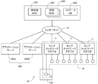
- FIG. 2 is a diagram showing an example of the sensor network system 10 including the metadata generation apparatus 100 according to the present embodiment.
- the sensor network system 10 includes a sensor network unit 14, a metadata generation device 100, a sensor management server 200, and an application server 300.
- the sensor network unit 14, the metadata generation device 100, the sensor management server 200, and the application server 300 are connected to each other via the Internet 15 so as to be able to communicate with each other.
- the number of components (sensor management server 200, application server 300, sensor network adapter 11, sensing device 12, and metadata generation apparatus 100, etc.) included in the sensor network system 10 is limited to that shown in FIG. Not.
- sensing data generated by the sensing device 12 or the like can be distributed.
- sensing data generated by the sensing device 12 can be distributed to the sensor management server 200
- sensing data generated by a virtual sensor generated by the sensor management server 200
- the sensor network unit 14 includes, for example, a plurality of sensor network adapters 11.
- a plurality of sensing devices 12 are connected to each of the plurality of sensor network adapters 11, and each sensing device 12 is connected to the Internet 15 via the sensor network adapter 11.
- the sensing device 12 is configured to obtain sensing data by observing an object.
- the sensing device 12 includes, for example, an image sensor (camera), a temperature sensor, a humidity sensor, an illuminance sensor, a force sensor, a sound sensor, a speed sensor, an acceleration sensor, an RFID (Radio Frequency IDentification) sensor, an infrared sensor, a posture sensor, and a rain sensor. Including radioactivity sensors and gas sensors.
- the sensing device 12 does not necessarily need to be a fixed type, and may be a mobile type such as a mobile phone, a smartphone, and a tablet.
- each sensing device 12 does not necessarily need to be comprised with the single sensor, and may be comprised with the some sensor.
- the sensing device 12 may be installed for any purpose. For example, for factory FA (Factory Automation) and production management, urban traffic control, environmental measurement such as weather, health care, crime prevention, etc. It may be installed.
- each sensor network adapter 11 is disposed at a separate (distant) location, and each sensing device 12 connected to each sensor network adapter 11 is disposed at the same (near) location.
- These arrangement locations are not limited to this.
- the metadata generation apparatus 100 is configured to generate metadata associated with the sensing device 12.
- the sensing device 12 is accommodated in the metadata generation apparatus 100 when the sensing device 12 is shipped, when the sensing device 12 is installed in the usage environment, or when the sensing device 12 is maintained.
- the metadata generation apparatus 100 In a state where the sensing device 12 is housed inside, the metadata generation apparatus 100 generates metadata of the sensing device 12.
- the metadata indicates, for example, the input / output relationship of the sensing device 12.
- the generated metadata is transmitted to the sensor management server 200 via, for example, the Internet 15 and registered in the metadata DB 292 (described later). The details of the metadata and the method for generating the metadata will be described in detail later.
- Each application server 300 (300A, 300B) is configured to execute an application that uses sensing data, and is realized by, for example, a general-purpose computer.
- the application server 300 acquires necessary sensing data via the Internet 15.
- the sensor management server 200 is a server for realizing a virtual sensor and managing each sensing device 12.
- a plurality of processing modules 254 and a preprocessing module 252 are realized, and a metadata DB 292 is managed.
- Each of the plurality of processing modules 254 and the preprocessing module 252 is, for example, a software module.
- the processing module 254 includes at least one input port, and is configured to generate output data different from the input data based on the input data input to each input port.
- the processing module 254 can switch the sensing device 12 that outputs input data to the input port as necessary. For example, when the sensing device 12 that is currently outputting input data to the input port fails, the processing module 254 can switch the input sensor to another sensing device 12.
- the processing module 254 may be configured to output data indicating the number of persons existing in the room based on, for example, input data (voice data) output by a sound sensor arranged in the room.
- input data voice data
- a virtual sensor that detects the number of people in the room can be realized by the processing module 254 and the sensing device 12 (sound sensor).
- the preprocessing module 252 is configured to preprocess input data to the processing module 254.
- the metadata DB 292 is configured to manage metadata associated with each sensing device 12 included in the sensor network unit 14.
- the preprocessing module 252 determines whether or not to preprocess the input data to the processing module 254 by referring to the metadata DB 292, for example.
- the metadata DB 292 Each software module and metadata DB 292 will be described in detail later.
- the metadata managed in the metadata DB 292 may be used, for example, to select the sensing device 12 that outputs sensing data to the processing module 254, or weighting of a plurality of input data in the processing module 254. It may be used for optimization. That is, various forms of metadata can be used.
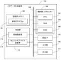
- FIG. 3 is a diagram illustrating an example of a hardware configuration of the metadata generation apparatus 100.
- the metadata generation apparatus 100 is realized by, for example, a housing unit that houses the sensing device 12 and a general-purpose computer that adjusts the internal environment of the housing unit.
- the metadata generation apparatus 100 includes a storage unit 170, a control unit 180, a communication I / F (interface) 195, an input unit 196, an output unit 197, and a storage unit 190. Each component is electrically connected via a bus 198.
- the housing part 170 is configured to form a sealed space inside, and the sensing device 12 is housed in the sealed space.
- the accommodating part 170 is a box-shaped member capable of forming a sealed space inside.
- the storage unit 170 includes an environment adjustment unit 172 and a sensing device installation unit 174.
- the environment adjustment unit 172 is configured to adjust the environment inside the storage unit 170. For example, the environment adjustment unit 172 adjusts the temperature inside the storage unit 170 to the temperature indicated by the instruction from the control unit 180.
- the environment adjusting unit 172 includes, for example, an air conditioning device.
- the sensing device installation unit 174 is configured to be electrically connectable to the sensing device 12. The sensing device 12 outputs sensing data to the control unit 180 via the bus 198 while being installed in the sensing device installation unit 174.
- the control unit 180 includes a CPU (Central Processing Unit) 182, a RAM (Random Access Memory) 184, a ROM (Read Only Memory) 186, and the like, and is configured to control each component according to information processing. .
- CPU Central Processing Unit
- RAM Random Access Memory
- ROM Read Only Memory
- the communication I / F 195 is configured to communicate with an external device (for example, the sensor management server 200 (FIG. 2)) provided outside the metadata generation device 100 via the Internet 15.
- the communication I / F 195 includes, for example, a wired LAN (Local Area Network) module or a wireless LAN module.
- the input unit 196 includes, for example, an input I / F such as a touch panel, a keyboard, and an input button.
- the input unit 196 receives an instruction to start generating metadata associated with the sensing device 12 installed in the storage unit 170 from the user.
- the output unit 197 includes, for example, an output I / F such as a display and a speaker.
- the output unit 197 is configured to output information about the generated metadata (image output, audio output, etc.).
- the storage unit 190 is an auxiliary storage device such as a hard disk drive or a solid state drive.
- the storage unit 190 is configured to store a control program 191, for example.
- the control program 191 is a control program for the metadata generation apparatus 100 that is executed by the control unit 180.
- the environment in the storage unit 170 is adjusted by the control unit 180 executing the control program 191.
- the control program 191 is expanded in the RAM 184.
- the control unit 180 controls each component by interpreting and executing the control program 191 expanded in the RAM 184 by the CPU 182.
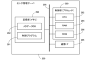
- FIG. 4 is a diagram illustrating an example of a hardware configuration of the sensor management server 200.
- the sensor management server 200 is realized by a general-purpose computer, for example.
- the sensor management server 200 includes a control unit 280, a communication I / F 295, and a storage unit 290, and each component is electrically connected via a bus 298.
- the control unit 280 includes a CPU 282, a RAM 284, a ROM 286, and the like, and is configured to control each component according to information processing.
- the communication I / F 295 communicates with external devices (for example, the metadata generation device 100, the application server 300, and the sensor network unit 14 (FIG. 2)) provided outside the sensor management server 200 via the Internet 15. It is configured.
- the communication I / F 295 is constituted by, for example, a wired LAN module or a wireless LAN module.
- the storage unit 290 is an auxiliary storage device such as a hard disk drive or a solid state drive.
- the storage unit 290 is configured to store, for example, a metadata DB 292 and a control program 291.
- the metadata DB 292 manages the metadata of each sensing device 12 included in the sensor network unit 14.
- Each metadata managed by the metadata DB 292 is generated by the metadata generation device 100, for example.
- the metadata generated by the metadata generation apparatus 100 is, for example, the correspondence (input) between the physical quantity input to the sensing device 12 and the output value of the sensing device 12 when the physical quantity is input. Output relation). Details of the metadata will be described in detail later.
- the control program 291 is a control program of the sensor management server 200 that is executed by the control unit 280.
- the processing module 254 and the preprocessing module 252 may be realized by the control unit 280 executing the control program 291.
- the control program 291 is expanded in the RAM 284.
- the control unit 280 controls each component by interpreting and executing the control program 291 expanded in the RAM 284 by the CPU 282.
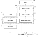
- FIG. 5 is a diagram illustrating an example of a software configuration of the metadata generation apparatus 100.
- the control unit 180 executes the control program 191 (FIG. 3)
- the environment control unit 150 controls the probability density function generation unit 152 and the metadata generation unit 154.
- the metadata transmission unit 156 Is realized.
- the environment control unit 150 receives an instruction from the user via the input unit 196 and adjusts the environment in the storage unit 170 (FIG. 3). Specifically, the environment control unit 150 controls the environment adjustment unit 172 so that the environment in the storage unit 170 becomes a target value. For example, the environment control unit 150 controls the environment adjustment unit 172 so that the temperature in the housing unit 170 becomes the target temperature. Note that the accuracy of environmental adjustment by the environmental adjustment unit 172 is higher than the detection accuracy of the environment by the sensing device 12. Therefore, the target value of the environment instructed by the environment control unit 150 is closer to the actual environment in the housing unit 170 than the output value of the sensing device 12.
- the sensing device 12 When the environment in the storage unit 170 reaches the target value, the physical quantity under the environment is input to the sensing device 12.
- the sensing device 12 generates sensing data based on the input physical quantity, and outputs the generated sensing data.
- the probability density function generation unit 152 collects sensing data output by the sensing device 12.
- the probability density function generation unit 152 is input with a specific physical quantity (physical quantity corresponding to the environment adjusted by the environment adjustment unit 172) based on the collected data and the target value of the environment in the storage unit 170.
- a probability density function of the output value of the sensing device 12 in the case is generated.
- the probability density function generation unit 152 generates a plurality of probability density functions by changing the environment in the accommodation unit 170 by the environment adjustment unit 172 (by changing the physical quantity input to the sensing device 12). Is done.
- each of the plurality of probability density functions has a specific physical quantity different from the specific physical quantity input to the sensing device 12 when the other probability density functions included in the plurality of probability density functions are generated in the sensing device 12. This is a probability density function of sensing data (output value) when input.
- the metadata generation unit 154 generates metadata based on the plurality of probability density functions generated by the probability density function generation unit 152.
- the metadata generated by the metadata generation unit 154 is metadata associated with the sensing device 12 installed in the sensing device installation unit 174 (FIG. 3).
- FIG. 6 is a diagram illustrating an example of metadata generated by the metadata generation unit 154.
- the sensing device 12 is a temperature sensor.
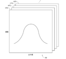
- the metadata 160 includes a probability density function of sensing data (output value) when the temperature in the storage unit 170 is 15 ° C., and a probability of sensing data when the temperature in the storage unit 170 is 16 ° C. It includes a density function, a probability density function of sensing data when the temperature in the accommodating part 170 is 17 ° C., and a probability density function of sensing data when the temperature in the accommodating part 170 is 18 ° C. These probability density functions indicate the input / output relationship of the sensing device 12 in detail.
- the metadata transmission unit 156 includes information that can identify the metadata generated by the metadata generation unit 154 and the sensing device 12 installed in the sensing device installation unit 174 (hereinafter, “ Is also transmitted to the sensor management server 200 via the communication I / F 195.
- the sensing device identification information is, for example, an ID (identification) allocated in advance to the sensing device 12 by the sensor management server 200 or the IP address of the sensing device 12.
- the transmitted metadata is registered in the metadata DB 292 (FIG. 2) in the sensor management server 200.
- FIG. 7 is a diagram illustrating an example of a software configuration of the sensor management server 200.
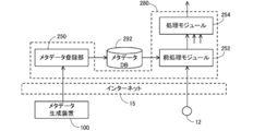
- the metadata registration unit 250, the preprocessing module 252, and the processing module 254 are realized by the control unit 280 executing the control program 291 (FIG. 4).
- the metadata registration unit 250 receives metadata and sensing device specifying information from the metadata generation apparatus 100 via the Internet 15.
- the metadata registration unit 250 registers the received metadata in the metadata DB 292 in association with the sensing device 12 specified by the sensing device specifying information.
- the metadata registered in the metadata DB 292 is used for various purposes.
- the metadata is used for preprocessing input data to the processing module 254, for example.
- the pre-processing module 252 reads metadata associated with the sensing device 12 that is outputting input data to the processing module 254 from the metadata DB 292. The preprocessing module 252 determines whether or not preprocessing for input data is necessary based on the read metadata. If it is determined that preprocessing is necessary, the preprocessing module 252 performs preprocessing on the input data. A method for determining the necessity of pre-processing will be described in detail later.
- the preprocessed input data is input to the processing module 254.
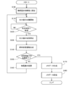
- FIG. 8 is a flowchart illustrating an example of a metadata generation operation in the metadata generation apparatus 100.
- the processing shown in this flowchart is performed when, for example, a metadata generation instruction is received from the user via the input unit 196 with the sensing device 12 installed in the sensing device installation unit 174 (FIG. 3).
- the unit 180 is executed by functioning as the environment control unit 150 (FIG. 5), the probability density function generation unit 152, the metadata generation unit 154, or the metadata transmission unit 156.
- control unit 180 controls environment adjustment unit 172 so that the physical quantity input to sensing device 12 installed in sensing device installation unit 174 becomes an initial value (step S100).
- the initial value of the physical quantity is determined in advance in the control program 191 (FIG. 3), for example.
- control unit 180 starts collecting sensing data (output value) output by the sensing device 12 (step S110).
- the controller 180 determines whether or not a predetermined time T1 has elapsed since the start of sensing data collection (step S120). When it is determined that predetermined time T1 has not elapsed (NO in step S120), control unit 180 continues collecting sensing data until predetermined time T1 has elapsed.
- the predetermined time T1 is a time during which the amount of sensing data necessary for generating a probability density function described later can be collected, and is predetermined in the control program 191.
- control unit 180 stops collecting sensing data (step S130). Then, the control unit 180 receives a specific physical quantity (a physical quantity corresponding to the environment adjusted by the environment adjusting unit 172) based on the physical quantity input to the sensing device 12 and the collected sensing data. The probability density function of the output value of the sensing device 12 is generated (step S140).
- the control unit 180 determines whether or not the collection of sensing data with all physical quantities predetermined in the control program 191 has ended (step S150).
- each type of the sensing device 12 temperature sensor, humidity sensor, sound pressure sensor, speed sensor, acceleration sensor, etc.
- a plurality of types of physical quantities are predetermined.
- the control program 191 determines, for example, a plurality of types of temperatures input to the sensing device 12 (for example, 10 It is predetermined that the temperature is changed by 1 ° C. from 30 ° C. to 30 ° C.).
- step S150 If it is determined in step S150 that the collection of sensing data for all physical quantities is not completed (NO in step S150), the control unit 180 is input to the sensing device 12 by controlling the environment adjustment unit 172. The physical quantity to be changed is changed (step S160). And the control part 180 repeats the process from step S110 to step S150 until the collection of the sensing data by all the physical quantities is complete
- control unit 180 determines whether the collection of sensing data for all physical quantities has been completed (YES in step S150). If it is determined in step S150 that the collection of sensing data for all physical quantities has been completed (YES in step S150), control unit 180 generates metadata based on the generated plurality of probability density functions. . The control unit 180 controls the communication I / F 195 so as to transmit the sensing device specifying information of the sensing device 12 installed in the sensing device installation unit 174 and the generated metadata to the sensor management server 200 (step S180). ).
- the metadata of the sensing device 12 is generated based on the probability density function of the output value of the sensing device 12 when a specific physical quantity is input.
- the probability density function the difference in the input / output relationship of each sensing device 12 to which the same product number is assigned and the fluctuation of the output value in the same sensing device 12 are sufficiently expressed. Therefore, according to the metadata generation apparatus 100, metadata that more accurately indicates the input / output relationship of each sensing device 12 can be generated.
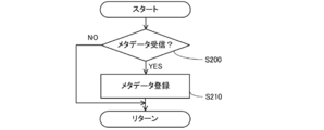
- FIG. 9 is a flowchart illustrating an example of metadata registration operation in the sensor management server 200. The processing shown in this flowchart is executed by the control unit 280 functioning as the metadata registration unit 250 (FIG. 7) while the sensor management server 200 is operating.
- control unit 280 determines whether or not metadata and sensing device specifying information have been received from metadata generation apparatus 100 via communication I / F 295 (step S200). If it is determined that the metadata and the sensing device specifying information have not been received (NO in step S200), the process proceeds to return.
- control unit 280 associates the received metadata and sensing device identification information with each other and registers them in metadata DB 292 ( Step S210).
- FIG. 10 is a flowchart showing an example of the preprocessing operation in the sensor management server 200.
- the processing illustrated in this flowchart is executed by the control unit 280 functioning as the preprocessing module 252.
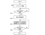
- control unit 280 starts buffering of sensing data output by sensing device 12 (step S300).
- the sensing data is temporarily stored in a partial area of storage unit 290 (FIG. 4).
- the control unit 280 determines whether or not the predetermined time T2 has elapsed after starting sensing data buffering (step S310). If it is determined that predetermined time T2 has not elapsed (NO in step S310), control unit 280 continues to buffer sensing data until predetermined time T2 has elapsed.
- the predetermined time T2 is a time during which an amount of sensing data necessary for environment estimation in step S320 (described later) can be collected, and is predetermined in the control program 291.
- control unit 280 includes metadata associated with the sensing device 12 that is outputting input data to the processing module 254, and buffering. Based on the sensed data, the current environment around the sensing device 12 is estimated (step S320).
- control unit 280 generates a probability density function of the buffered sensing data, and calculates a similarity between the generated probability density function and each of the plurality of probability density functions included in the metadata. To do. Various known methods can be used to calculate the similarity.
- the control unit 280 extracts a probability density function having the highest similarity to the probability density function of the buffered sensing data from among the plurality of probability density functions included in the metadata.
- the control unit 280 estimates that the physical quantity associated with the extracted probability density function indicates the current environment around the sensing device 12.
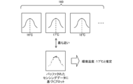
- FIG. 11 is a diagram for explaining an example of a method for estimating the current environment around the sensing device 12.
- the sensing device 12 outputting input data to the processing module 254 is a temperature sensor.
- the metadata 160 includes a probability density function of sensing data when the temperature (physical quantity input to the sensing device 12) is 16 ° C., a probability density function of sensing data when the temperature is 17 ° C., and a temperature of 18 Includes the probability density function of the sensing data in the case of ° C.
- the control unit 280 generates a probability density function of the buffered sensing data, and calculates a similarity between the generated probability density function and each of the plurality of probability density functions included in the metadata 160.
- the similarity between the probability density function of the buffered sensing data and the probability density function when the temperature is 17 ° C. is the highest.
- the control unit 280 estimates that the current temperature around the sensing device 12 is 17 ° C.
- control unit 280 continuously determines whether or not preprocessing is necessary and performs preprocessing when necessary (Ste S330). Specifically, the control unit 280 extracts a probability density function corresponding to the environment estimated in step S320 from a plurality of probability density functions included in the metadata associated with the sensing device 12. . The control unit 280 determines whether or not preprocessing is necessary by using the extracted probability density function, and performs preprocessing when necessary.
- FIG. 12 is a diagram for explaining a method for determining whether or not preprocessing is necessary, and an example of preprocessing.
- the metadata 160 output values of V1 or lower and V2 or higher are predetermined as outliers.
- the reference (V1, V2) of the outlier is determined by the control unit 180 (FIG. 3) when the metadata 160 is generated, for example.
- the control program 191 executed by the control unit 180 it is predetermined that an output value whose appearance frequency (probability) is less than a predetermined value is regarded as an outlier.
- the control unit 280 can regard output values of V1 or lower and V2 or higher as outliers by referring to a probability density function corresponding to the current environment (temperature: 17 ° C.). Therefore, when the sensing data output by the sensing device 12 is V1 or lower or V2 or higher, the control unit 280 determines that the sensing data is an outlier and needs preprocessing. Then, when the sensing data is an outlier, for example, the control unit 280 deletes the outlier as preprocessing.
- control unit 280 determines whether or not a predetermined time T3 has elapsed since the processing in step S330 was started (step S340). When it is determined that the predetermined time T3 has not elapsed (NO in step S340), the control unit 280 determines whether or not preprocessing is necessary and performs preprocessing when necessary until the predetermined time T3 has elapsed. continue.
- the predetermined time T3 is a time during which the environment estimated in step S320 hardly changes, and is predetermined in the control program 291. On the other hand, when it is determined that predetermined time T3 has elapsed (YES in step S340), the process proceeds to return.
- metadata probability density function
- the sensing device 12 determines whether or not preprocessing of input data to the processing module 254 is necessary.
- the sensor management server 200 for example, by using the reference values (V1, V2 (FIG. 12)) determined as outliers included in the metadata, it is possible to easily determine whether or not preprocessing is necessary.
- the metadata of the sensing device 12 is generated based on the probability density function of the output value of the sensing device 12 when a specific physical quantity is input.
- the probability density function the difference in the input / output relationship of each sensing device 12 to which the same product number is assigned and the fluctuation of the output value in the same sensing device 12 are sufficiently expressed. Therefore, according to the metadata generation apparatus 100, metadata that more accurately indicates the input / output relationship of each sensing device 12 can be generated.
- the sensing device 12 is an example of the “sensing device” in the present invention
- the metadata generation apparatus 100 is an example of the “metadata generation apparatus” in the present invention.
- the probability density function generation unit 152 is an example of the “probability density function generation unit” of the present invention
- the metadata generation unit 154 is an example of the “metadata generation unit” of the present invention.
- the environment control unit 150 is an example of the “physical quantity specifying unit” in the present invention.
- the probability density function of the output value of the sensing device 12 when a specific physical quantity is input is used as metadata.
- the probability density function itself does not necessarily have to be metadata.
- the control unit 180 generates a probability density function, and determines outlier reference (V1, V2 in FIG. 12) based on the generated probability density function. Then, the control unit 180 may use the generated outlier reference as metadata.
- the metadata generation apparatus 100 is provided separately from the sensing device 12.
- the metadata generation apparatus 100 is not necessarily separate from the sensing device 12.
- the sensing device 12 and the metadata generation apparatus 100 may be integrated. That is, the sensing device 12 may have a metadata generation function.
- the sensing device 12 is installed in the sensing device installation unit 174 in advance.
- the storage unit 170 is opened, and the sensing device 12 can observe the surrounding environment (the environment outside the storage unit 170).
- metadata was produced
- the metadata does not necessarily have to be generated in a state where the sensing device 12 is sealed in the housing unit 170.
- the metadata may be generated in a state where the sensing device 12 is installed in an actual use environment.
- the metadata generation apparatus 100 does not include the accommodating unit 170.
- the metadata generation apparatus 100 includes a sensor (reference machine) with higher accuracy than the sensing device 12 that is the generation target of the metadata.
- this sensor has an environmental detection accuracy one digit or more higher than that of the sensing device 12.
- the control unit 180 continues the collection of the physical quantity detected by the sensor and the collection of the sensing data generated by the sensing device 12 for a predetermined time.
- the control unit 180 associates the physical quantity collected at the same time with the sensing data.
- the control unit 180 generates a plurality of probability density functions of output values of the sensing device 12 when a specific physical quantity is input, based on the collected physical quantity and sensing data.
- Each probability density function is a probability density function of an output value when a different physical quantity is input to the sensing device 12.
- the control part 180 produces
- the metadata is generated by such a method, the metadata is generated based on the sensing data in the actual usage environment. Therefore, the metadata indicating the input / output relationship of the sensing device 12 in the actual usage environment is generated. Can do.
- the processing performed by the sensor management server 200 may be realized by a plurality of servers or the like.
Landscapes
- Engineering & Computer Science (AREA)
- Theoretical Computer Science (AREA)
- Physics & Mathematics (AREA)
- General Engineering & Computer Science (AREA)
- General Physics & Mathematics (AREA)
- Quality & Reliability (AREA)
- Computing Systems (AREA)
- Databases & Information Systems (AREA)
- Library & Information Science (AREA)
- Evolutionary Biology (AREA)
- Bioinformatics & Computational Biology (AREA)
- Life Sciences & Earth Sciences (AREA)
- Probability & Statistics with Applications (AREA)
- Computer Hardware Design (AREA)
- Bioinformatics & Cheminformatics (AREA)
- Data Mining & Analysis (AREA)
- Business, Economics & Management (AREA)
- General Business, Economics & Management (AREA)
- Computer Networks & Wireless Communication (AREA)
- Testing Or Calibration Of Command Recording Devices (AREA)
- Selective Calling Equipment (AREA)
Abstract
各センシングデバイスの入出力関係をより正確に示すメタデータを生成可能なメタデータ生成装置、メタデータ生成方法及びプログラムを提供する。センシングデバイスは、入力される物理量に基づいて出力値を生成するように構成されている。メタデータ生成装置は、確率密度関数生成部と、メタデータ生成部とを備える。確率密度関数生成部は、センシングデバイスに特定の物理量が入力された場合における出力値の確率密度関数を生成するように構成されている。メタデータ生成部は、確率密度関数に基づいてメタデータを生成するように構成されている。
Description
本発明は、メタデータ生成装置、メタデータ生成方法及びプログラムに関する。
国際公開WO2015/128954号公報(特許文献1)は、デバイスネットワークと、該デバイスネットワークに含まれる各デバイス(たとえば、センサ)を管理するデバイス管理システムとを含むデバイスネットワークシステムを開示する。デバイス管理システムにおいては、デバイスネットワークに含まれる各デバイスの属性情報を管理する物理デバイスマスターDB(database)が設けられている。ユーザは、物理デバイスマスターDBを参照することによって、デバイスネットワークに含まれる複数のデバイスのうち所望の属性を有するデバイスを検索することができる(特許文献1参照)。
上記特許文献1においては、各デバイスの「種別」及び「設置箇所」等を示す情報が物理デバイスマスターDBで管理される。すなわち、物理デバイスマスターDBにおいては、「種別」及び「設置箇所」を示す情報がメタデータとして各デバイスに付与されているといえる。たとえば、ユーザは、該メタデータを参照することによって、「種別」及び「設置箇所」に関して所望の条件を満たすデバイスを検索することができる。
たとえば、センシングデバイスには、各「メーカ」の「品番」毎にデータシートが設けられる。データシートには、センシングデバイスに入力される物理量と、該物理量が入力された場合のセンシングデバイスの出力値との対応関係(以下、「入出力関係」とも称する。)を示す情報(以下、「入出力関係情報」とも称する。)が含まれる場合が多い。本発明者は、たとえば、所望の入出力関係を有するセンシングデバイスの検索のために、入出力関係情報をメタデータとして各センシングデバイスに付与することが有効であると考えた。
しかしながら、データシートに含まれる入出力関係情報は、あくまでも代表的なものである。したがって、同一の「メーカ」、「品番」のセンシングデバイスであっても、厳密にはセンシングデバイス毎に異なる入出力関係を有する場合もある。また、同一のセンシングデバイスに同一の物理量が入力された場合であっても、様々な要因(センシングデバイスの設置状態、周囲環境等)により、センシングデバイスによって異なる値が出力される(出力値がぶれる)こともある。すなわち、データシートに含まれる入出力関係情報は、必ずしも各センシングデバイスの入出力関係を正確に示しているとはいえない。
本発明は、このような問題を解決するためになされたものであって、その目的は、各センシングデバイスの入出力関係をより正確に示すメタデータを生成可能なメタデータ生成装置、メタデータ生成方法及びプログラムを提供することである。
本発明のある局面に従うメタデータ生成装置は、センシングデバイスに対応付けられるメタデータを生成するように構成されている。センシングデバイスは、入力される物理量に基づいて出力値を生成するように構成されている。メタデータ生成装置は、確率密度関数生成部と、メタデータ生成部とを備える。確率密度関数生成部は、センシングデバイスに特定の物理量が入力された場合における出力値の確率密度関数を生成するように構成されている。メタデータ生成部は、確率密度関数に基づいてメタデータを生成するように構成されている。
このメタデータ生成装置においては、特定の物理量が入力された場合におけるセンシングデバイスの出力値の確率密度関数に基づいてメタデータが生成される。該確率密度関数によれば、同一品番が付与された各センシングデバイスの入出力関係の違い、及び、同一のセンシングデバイスにおける出力値のぶれが十分に表される。したがって、このメタデータ生成装置によれば、各センシングデバイスの入出力関係をより正確に示すメタデータを生成することができる。
また、上記メタデータ生成装置において、確率密度関数生成部は、複数の確率密度関数を生成するように構成されてもよい。複数の確率密度関数の各々は、複数の確率密度関数に含まれる他の確率密度関数の生成時にセンシングデバイスに入力された特定の物理量とは異なる特定の物理量がセンシングデバイスに入力された場合における出力値の確率密度関数であってもよい。
このメタデータ生成装置においては、物理量(入力値)毎に出力値の確率密度関数が生成され、生成された複数の確率密度関数に基づいてメタデータが生成される。したがって、このメタデータ生成装置によれば、各センシングデバイスの入出力関係をより詳細に示すメタデータを生成することができる。
また、上記メタデータ生成装置は、センシングデバイスに入力される物理量をセンシングデバイスよりも高精度に特定するように構成された物理量特定部をさらに備えてもよい。確率密度関数生成部は、物理量特定部によって特定された物理量と出力値とに基づいて確率密度関数を生成するように構成されてもよい。
このメタデータ生成装置においては、物理量特定部によってセンシングデバイスに入力される物理量が特定され、物理量特定部による物理量の特定精度はセンシングデバイスよりも高い。したがって、このメタデータ生成装置によれば、センシングデバイスに入力される物理量が高精度に特定されるため、センシングデバイスの入出力関係を高精度に特定することができる。
また、センシングデバイスは、実際の使用環境において設置されていてもよい。
このメタデータ生成装置によれば、実際の使用環境におけるセンシングデバイスの入出力関係を示すメタデータを生成することができる。
また、本発明の別の曲面に従うメタデータ生成方法は、センシングデバイスに対応付けられるメタデータを生成する。センシングデバイスは、入力される物理量に基づいて出力値を生成するように構成されている。メタデータ生成方法は、センシングデバイスに特定の物理量が入力された場合における出力値の確率密度関数を生成するステップと、確率密度関数に基づいてメタデータを生成するステップとを含む。
このメタデータ生成方法においては、特定の物理量が入力された場合におけるセンシングデバイスの出力値の確率密度関数に基づいてメタデータが生成される。該確率密度関数によれば、各センシングデバイスの入出力関係の違い、及び、同一のセンシングデバイスにおける出力値のぶれが十分に表される。したがって、このメタデータ生成方法によれば、各センシングデバイスの入出力関係をより正確に示すメタデータを生成することができる。
また、本発明の別の局面に従うプログラムは、センシングデバイスに対応付けられるメタデータを生成する処理をコンピュータに実行させる。センシングデバイスは、入力される物理量に基づいて出力値を生成するように構成されている。プログラムは、センシングデバイスに特定の物理量が入力された場合における出力値の確率密度関数を生成するステップと、確率密度関数に基づいてメタデータを生成するステップとをコンピュータに実行させるように構成されている。
このプログラムがコンピュータによって実行されると、特定の物理量が入力された場合におけるセンシングデバイスの出力値の確率密度関数に基づいてメタデータが生成される。該確率密度関数によれば、各センシングデバイスの入出力関係の違い、及び、同一のセンシングデバイスにおける出力値のぶれが十分に表される。したがって、このプログラムによれば、各センシングデバイスの入出力関係をより正確に示すメタデータを生成することができる。
本発明によれば、各センシングデバイスの入出力関係をより正確に示すメタデータを生成可能なメタデータ生成装置、メタデータ生成方法及びプログラムを提供することができる。
以下、本発明の一側面に係る実施の形態(以下、「本実施の形態」とも称する。)について、図面を用いて詳細に説明する。なお、図中同一又は相当部分には同一符号を付してその説明は繰り返さない。また、以下で説明する本実施の形態は、あらゆる点において本発明の例示にすぎない。本実施の形態は、本発明の範囲内において、種々の改良や変更が可能である。すなわち、本発明の実施にあたっては、実施の形態に応じて具体的構成を適宜採用することができる。
[1.概要]
図1は、本実施の形態に従うメタデータ生成装置100の概要を説明するための図である。図1に示されるように、センシングデバイス12は、入力される物理量(たとえば、温度、湿度、音圧、速度、加速度)に基づいてセンシングデータを生成し、生成されたセンシングデータ(出力値)を出力する。
図1は、本実施の形態に従うメタデータ生成装置100の概要を説明するための図である。図1に示されるように、センシングデバイス12は、入力される物理量(たとえば、温度、湿度、音圧、速度、加速度)に基づいてセンシングデータを生成し、生成されたセンシングデータ(出力値)を出力する。
たとえば、複数のセンシングデバイス12から一部のセンシングデバイス12を選択し、所望の仮想センサを生成する場合を考える。仮想センサとは、入力センサ(たとえば、センシングデバイス12)が対象を観測することによって生成されたセンシングデータに基づいて、入力センサによって観測された対象とは異なる対象の観測結果をセンシングデータとして出力するセンサモジュールである。たとえば、仮想センサは、1又は複数のセンシングデバイス12と、処理モジュール(後述)とによって構成される。たとえば、処理モジュールは複数の入力ポートを有し、各入力ポートにはセンシングデバイス12によって出力されたセンシングデータが入力される。処理モジュールは、入力されたセンシングデータ(以下、「入力データ」とも称する。)に基づいて入力データとは異なる出力データを生成するように構成されている。
所望の仮想センサを生成するためには、処理モジュールの入力センサとして適切なセンシングデバイス12を選択することが重要である。すなわち、複数のセンシングデバイス12から適切なセンシングデバイス12を検索することが重要である。また、仮想センサを生成する場合以外にも、複数のセンシングデバイス12から適切なセンシングデバイス12を検索することが重要な場面は多々存在すると考えられる。
適切なセンシングデバイス12の検索を容易にするために、各センシングデバイス12に該センシングデバイス12の属性を示すメタデータを対応付けることが考えられる。各センシングデバイス12に該メタデータが対応付けられている場合には、たとえば、該メタデータを参照するだけで適切なセンシングデバイス12を検索することができる。センシングデバイス12の重要な属性の一つは、センシングデバイス12に入力される物理量と、該物理量が入力された場合のセンシングデバイス12の出力値との対応関係(入出力関係)である。
各センシングデバイス12には、各「メーカ」の「品番」毎にデータシートが設けられている。データシートには、センシングデバイス12の入出力関係情報が含まれる場合が多い。本発明者は、たとえば、所望の入出力関係を有するセンシングデバイス12の検索のために、入出力関係情報をメタデータとして各センシングデバイス12に付与することが有効であると考えた。
しかしながら、データシートに含まれる入出力関係情報は、あくまでも代表的なものである。したがって、同一の「メーカ」、「品番」のセンシングデバイス12であっても、厳密にはセンシングデバイス12毎に異なる入出力関係を有する場合もある。また、同一のセンシングデバイス12に同一の物理量が入力された場合であっても、様々な要因(センシングデバイス12の設置状態、周囲環境等)により、センシングデバイス12によって異なる値が出力される(出力値がぶれる)こともある。すなわち、データシートに含まれる入出力関係情報は、必ずしも各センシングデバイス12の入出力関係を正確に示しているとはいえない。
本実施の形態に従うメタデータ生成装置100は、確率密度関数生成部152と、メタデータ生成部154とを備える。確率密度関数生成部152は、センシングデバイス12に特定の物理量が入力された場合における出力値の確率密度関数を生成するように構成されている。メタデータ生成部154は、確率密度関数生成部152によって生成された確率密度関数に基づいてメタデータを生成するように構成されている。すなわち、メタデータ生成装置100においては、特定の物理量が入力された場合におけるセンシングデバイス12の出力値の確率密度関数に基づいて、センシングデバイス12のメタデータが生成される。該確率密度関数によれば、同一品番が付与された各センシングデバイス12の入出力関係の違い、及び、同一のセンシングデバイス12における出力値のぶれが十分に表される。したがって、メタデータ生成装置100によれば、各センシングデバイス12の入出力関係をより正確に示すメタデータを生成することができる。
[2.構成]
<2-1.システム全体の構成>
図2は、本実施の形態に従うメタデータ生成装置100を含むセンサネットワークシステム10の一例を示す図である。図2の例において、センサネットワークシステム10は、センサネットワーク部14と、メタデータ生成装置100と、センサ管理サーバ200と、アプリケーションサーバ300とを含む。
<2-1.システム全体の構成>
図2は、本実施の形態に従うメタデータ生成装置100を含むセンサネットワークシステム10の一例を示す図である。図2の例において、センサネットワークシステム10は、センサネットワーク部14と、メタデータ生成装置100と、センサ管理サーバ200と、アプリケーションサーバ300とを含む。
センサネットワーク部14、メタデータ生成装置100、センサ管理サーバ200及びアプリケーションサーバ300は、インターネット15を介して相互に通信可能に接続されている。なお、センサネットワークシステム10に含まれる各構成要素(センサ管理サーバ200、アプリケーションサーバ300、センサネットワークアダプタ11、センシングデバイス12及びメタデータ生成装置100等)の数は、図2に示されるものに限定されない。
センサネットワークシステム10においては、センシングデバイス12等によって生成されたセンシングデータが流通可能である。たとえば、センシングデバイス12によって生成されたセンシングデータはセンサ管理サーバ200に流通し得るし、仮想センサ(センサ管理サーバ200によって生成される。)によって生成されたセンシングデータはアプリケーションサーバ300に流通し得る。
センサネットワーク部14は、たとえば、複数のセンサネットワークアダプタ11を含む。複数のセンサネットワークアダプタ11の各々には複数のセンシングデバイス12が接続されており、各センシングデバイス12はセンサネットワークアダプタ11を介してインターネット15に接続されている。
センシングデバイス12は、対象を観測することによってセンシングデータを得るように構成されている。センシングデバイス12は、たとえば、画像センサ(カメラ)、温度センサ、湿度センサ、照度センサ、力センサ、音センサ、速度センサ、加速度センサ、RFID(Radio Frequency IDentification)センサ、赤外線センサ、姿勢センサ、降雨センサ、放射能センサ及びガスセンサ等を含む。また、センシングデバイス12は、必ずしも固設型である必要はなく、携帯電話、スマートフォン及びタブレット等の移動型であってもよい。また、各センシングデバイス12は、必ずしも単一のセンサで構成されている必要はなく、複数のセンサによって構成されていてもよい。また、センシングデバイス12は、どのような目的で設置されていてもよく、たとえば、工場におけるFA(Factory Automation)及び生産管理、都市交通制御、気象等の環境計測、ヘルスケア並びに防犯等のために設置されていてもよい。
センサネットワーク部14において、たとえば、各センサネットワークアダプタ11は別々の(遠い)場所に配置され、各センサネットワークアダプタ11に接続される各センシングデバイス12は同一の(近い)場所に配置されるが、これらの配置場所はこれに限定されない。
メタデータ生成装置100は、センシングデバイス12に対応付けられるメタデータを生成するように構成されている。たとえば、センシングデバイス12の出荷時、センシングデバイス12の使用環境における設置時、又は、センシングデバイス12のメンテナンス時に、センシングデバイス12は、メタデータ生成装置100内に収容される。センシングデバイス12を内部に収容した状態で、メタデータ生成装置100は、センシングデバイス12のメタデータを生成する。メタデータは、たとえば、センシングデバイス12の入出力関係を示す。生成されたメタデータは、たとえば、インターネット15を介してセンサ管理サーバ200に送信され、メタデータDB292(後述)に登録される。メタデータの内容、及び、メタデータの生成方法については後程詳しく説明する。
各アプリケーションサーバ300(300A,300B)は、センシングデータを利用するアプリケーションを実行するように構成されており、たとえば、汎用のコンピュータによって実現されている。アプリケーションサーバ300は、インターネット15を介して必要なセンシングデータを取得する。
センサ管理サーバ200は、仮想センサを実現するとともに各センシングデバイス12を管理するためのサーバである。センサ管理サーバ200においては、複数の処理モジュール254と、前処理モジュール252とが実現されるとともに、メタデータDB292が管理される。複数の処理モジュール254及び前処理モジュール252の各々は、たとえば、ソフトウェアモジュールである。
上述のように、処理モジュール254は、少なくとも1つの入力ポートを含み、各入力ポートに入力される入力データに基づいて入力データとは異なる出力データを生成するように構成されている。処理モジュール254は、必要に応じて入力ポートへ入力データを出力するセンシングデバイス12を切り替え可能である。たとえば、現在入力ポートに入力データを出力しているセンシングデバイス12が故障した場合に、処理モジュール254は、入力センサを他のセンシングデバイス12に切り替えることができる。
処理モジュール254は、たとえば、室内に配置された音センサによって出力される入力データ(音声データ)に基づいて、該室内に存在する人の数を示すデータを出力するように構成されてもよい。この場合には、処理モジュール254と、センシングデバイス12(音センサ)とによって、室内の人の数を検知する仮想センサを実現することができる。
前処理モジュール252は、処理モジュール254への入力データに前処理を施すように構成されている。メタデータDB292は、センサネットワーク部14に含まれる各センシングデバイス12に対応付けられたメタデータを管理するように構成されている。
センサ管理サーバ200において、前処理モジュール252は、たとえば、メタデータDB292を参照することによって、処理モジュール254への入力データに前処理を施すか否かを決定する。各ソフトウェアモジュール及びメタデータDB292については後程詳しく説明する。
また、メタデータDB292において管理されるメタデータは、たとえば、処理モジュール254にセンシングデータを出力するセンシングデバイス12を選択するために用いられてもよいし、処理モジュール254における複数の入力データの重み付けの最適化に用いられてもよい。すなわち、このメタデータの用途としては、様々な形態が考えられる。
<2-2.メタデータ生成装置のハードウェア構成>
図3は、メタデータ生成装置100のハードウェア構成の一例を示す図である。なお、本実施の形態において、メタデータ生成装置100は、たとえば、センシングデバイス12を収容する収容部と、収容部の内部環境を調節する汎用コンピュータとによって実現される。
図3は、メタデータ生成装置100のハードウェア構成の一例を示す図である。なお、本実施の形態において、メタデータ生成装置100は、たとえば、センシングデバイス12を収容する収容部と、収容部の内部環境を調節する汎用コンピュータとによって実現される。
図3の例において、メタデータ生成装置100は、収容部170と、制御部180と、通信I/F(interface)195と、入力部196と、出力部197と、記憶部190とを含み、各構成は、バス198を介して電気的に接続されている。
収容部170は、内部に密閉空間を形成するように構成されており、該密閉空間にセンシングデバイス12が収容される。たとえば、収容部170は、内部に密閉空間を形成可能な箱状部材である。収容部170は、環境調節部172と、センシングデバイス設置部174とを含む。
環境調節部172は、収容部170内部の環境を調節するように構成されている。たとえば、環境調節部172は、収容部170内部の温度を、制御部180からの指示が示す温度に調節する。環境調節部172は、たとえば、冷暖房機器を含む。また、センシングデバイス設置部174は、センシングデバイス12を電気的に接続可能に構成されている。センシングデバイス設置部174に設置されている状態で、センシングデバイス12は、バス198を介して、センシングデータを制御部180に出力する。
制御部180は、CPU(Central Processing Unit)182、RAM(Random Access Memory)184及びROM(Read Only Memory)186等を含み、情報処理に応じて各構成要素の制御を行なうように構成されている。
通信I/F195は、インターネット15を介して、メタデータ生成装置100の外部に設けられた外部装置(たとえば、センサ管理サーバ200(図2))と通信するように構成されている。通信I/F195は、たとえば、有線LAN(Local Area Network)モジュールや無線LANモジュールで構成される。
入力部196は、たとえば、タッチパネル、キーボード、入力ボタン等の入力I/Fで構成されている。入力部196は、たとえば、収容部170内に設置されたセンシングデバイス12に対応付けられるメタデータの生成開始指示をユーザから受け付ける。
出力部197は、たとえば、ディスプレイ、スピーカ等の出力I/Fで構成されている。出力部197は、たとえば、生成されたメタデータに関する情報を出力(画像出力、音声出力等)するように構成されている。
記憶部190は、たとえば、ハードディスクドライブ、ソリッドステートドライブ等の補助記憶装置である。記憶部190は、たとえば、制御プログラム191を記憶するように構成されている。制御プログラム191は、制御部180によって実行されるメタデータ生成装置100の制御プログラムである。たとえば、制御部180が制御プログラム191を実行することによって、収容部170内の環境が調節される。制御部180が制御プログラム191を実行する場合に、制御プログラム191は、RAM184に展開される。そして、制御部180は、RAM184に展開された制御プログラム191をCPU182によって解釈及び実行することにより、各構成要素を制御する。
<2-3.センサ管理サーバのハードウェア構成>
図4は、センサ管理サーバ200のハードウェア構成の一例を示す図である。なお、本実施の形態において、センサ管理サーバ200は、たとえば、汎用コンピュータによって実現される。
図4は、センサ管理サーバ200のハードウェア構成の一例を示す図である。なお、本実施の形態において、センサ管理サーバ200は、たとえば、汎用コンピュータによって実現される。
図4の例において、センサ管理サーバ200は、制御部280と、通信I/F295と、記憶部290とを含み、各構成は、バス298を介して電気的に接続されている。
制御部280は、CPU282、RAM284及びROM286等を含み、情報処理に応じて各構成要素の制御を行なうように構成されている。
通信I/F295は、インターネット15を介して、センサ管理サーバ200の外部に設けられた外部装置(たとえば、メタデータ生成装置100、アプリケーションサーバ300及びセンサネットワーク部14(図2))と通信するように構成されている。通信I/F295は、たとえば、有線LANモジュールや無線LANモジュールで構成される。
記憶部290は、たとえば、ハードディスクドライブ、ソリッドステートドライブ等の補助記憶装置である。記憶部290は、たとえば、メタデータDB292と、制御プログラム291とを記憶するように構成されている。
メタデータDB292は、センサネットワーク部14に含まれる各センシングデバイス12のメタデータを管理する。メタデータDB292によって管理される各メタデータは、たとえば、メタデータ生成装置100によって生成される。上述のように、メタデータ生成装置100によって生成されるメタデータは、たとえば、センシングデバイス12に入力される物理量と、該物理量が入力された場合のセンシングデバイス12の出力値との対応関係(入出力関係)を示す。メタデータの詳細については、後程詳しく説明する。
制御プログラム291は、制御部280によって実行されるセンサ管理サーバ200の制御プログラムである。たとえば、制御部280が制御プログラム291を実行することによって、各処理モジュール254及び前処理モジュール252(図2)が実現されてもよい。制御部280が制御プログラム291を実行する場合に、制御プログラム291は、RAM284に展開される。そして、制御部280は、RAM284に展開された制御プログラム291をCPU282によって解釈及び実行することにより、各構成要素を制御する。
<2-4.メタデータ生成装置のソフトウェア構成>
図5は、メタデータ生成装置100のソフトウェア構成の一例を示す図である。図5の例においては、制御部180が制御プログラム191(図3)を実行することによって、環境制御部150と、確率密度関数生成部152と、メタデータ生成部154と、メタデータ送信部156とが実現される。
図5は、メタデータ生成装置100のソフトウェア構成の一例を示す図である。図5の例においては、制御部180が制御プログラム191(図3)を実行することによって、環境制御部150と、確率密度関数生成部152と、メタデータ生成部154と、メタデータ送信部156とが実現される。
環境制御部150は、入力部196を介したユーザからの指示を受けて、収容部170(図3)内の環境を調節する。具体的には、環境制御部150は、収容部170内の環境が目標値になるように環境調節部172を制御する。たとえば、環境制御部150は、収容部170内の温度が目標温度になるように環境調節部172を制御する。なお、環境調節部172による環境調節の精度は、センシングデバイス12による環境の検知精度よりも高い。したがって、環境制御部150によって指示された環境の目標値は、センシングデバイス12の出力値よりも、収容部170内の実際の環境に近い値を示す。
収容部170内の環境が目標値になると、その環境下における物理量がセンシングデバイス12に入力される。センシングデバイス12は、入力される物理量に基づいてセンシングデータを生成し、生成されたセンシングデータを出力する。
確率密度関数生成部152は、センシングデバイス12によって出力されるセンシングデータを収集する。確率密度関数生成部152は、収集されたデータと、収容部170内の環境の目標値とに基づいて、特定の物理量(環境調節部172によって調整された環境に対応する物理量)が入力された場合におけるセンシングデバイス12の出力値の確率密度関数を生成する。
環境調節部172により収容部170内の環境が変更されることによって(センシングデバイス12に入力される物理量が変更されることによって)、確率密度関数生成部152においては、複数の確率密度関数が生成される。この場合に、複数の確率密度関数の各々は、複数の確率密度関数に含まれる他の確率密度関数の生成時にセンシングデバイス12に入力された特定の物理量とは異なる特定の物理量がセンシングデバイス12に入力された場合におけるセンシングデータ(出力値)の確率密度関数である。
メタデータ生成部154は、確率密度関数生成部152によって生成された複数の確率密度関数に基づいてメタデータを生成する。メタデータ生成部154によって生成されるメタデータは、センシングデバイス設置部174(図3)に設置されているセンシングデバイス12に対応付けられるメタデータである。
図6は、メタデータ生成部154よって生成されるメタデータの一例を示す図である。図6の例においては、センシングデバイス12が温度センサである。この例において、メタデータ160は、収容部170内の温度が15℃である場合におけるセンシングデータ(出力値)の確率密度関数、収容部170内の温度が16℃である場合におけるセンシングデータの確率密度関数、収容部170内の温度が17℃である場合におけるセンシングデータの確率密度関数、及び、収容部170内の温度が18℃である場合におけるセンシングデータの確率密度関数を含む。これらの確率密度関数は、センシングデバイス12の入出力関係を詳細に示す。
再び図5を参照して、メタデータ送信部156は、メタデータ生成部154によって生成されたメタデータと、センシングデバイス設置部174に設置されているセンシングデバイス12を特定可能な情報(以下、「センシングデバイス特定情報」とも称する。)とを、通信I/F195を介してセンサ管理サーバ200に送信する。センシングデバイス特定情報は、たとえば、センサ管理サーバ200によってセンシングデバイス12に予め割り振られたID(identification)やセンシングデバイス12のIPアドレスである。送信されたメタデータは、センサ管理サーバ200においてメタデータDB292(図2)に登録される。
<2-5.センサ管理サーバのソフトウェア構成>
図7は、センサ管理サーバ200のソフトウェア構成の一例を示す図である。図7の例においては、制御部280が制御プログラム291(図4)を実行することによって、メタデータ登録部250と、前処理モジュール252と、処理モジュール254とが実現される。
図7は、センサ管理サーバ200のソフトウェア構成の一例を示す図である。図7の例においては、制御部280が制御プログラム291(図4)を実行することによって、メタデータ登録部250と、前処理モジュール252と、処理モジュール254とが実現される。
メタデータ登録部250は、インターネット15を介してメタデータ生成装置100からメタデータとセンシングデバイス特定情報とを受信する。メタデータ登録部250は、受信されたメタデータを、センシングデバイス特定情報によって特定されるセンシングデバイス12と対応付けてメタデータDB292に登録する。
メタデータDB292に登録されたメタデータは、様々な用途に用いられる。メタデータは、たとえば、処理モジュール254への入力データの前処理に用いられる。
前処理モジュール252は、処理モジュール254へ入力データを出力しているセンシングデバイス12に対応付けられているメタデータをメタデータDB292から読み出す。前処理モジュール252は、読み出されたメタデータに基づいて、入力データへの前処理の要否を判定する。前処理が必要であると判定されると、前処理モジュール252は、入力データに前処理を施す。前処理の要否の決定方法については後程詳しく説明する。
前処理モジュール252によって入力データに前処理が施されると、処理モジュール254には、前処理後の入力データが入力される。
[3.動作]
<3-1.メタデータ生成動作>
図8は、メタデータ生成装置100におけるメタデータの生成動作の一例を示すフローチャートである。このフローチャートに示される処理は、たとえば、センシングデバイス設置部174(図3)にセンシングデバイス12が設置された状態で、入力部196を介してユーザからメタデータの生成指示を受け付けた場合に、制御部180が環境制御部150(図5)、確率密度関数生成部152、メタデータ生成部154又はメタデータ送信部156として機能することによって実行される。
<3-1.メタデータ生成動作>
図8は、メタデータ生成装置100におけるメタデータの生成動作の一例を示すフローチャートである。このフローチャートに示される処理は、たとえば、センシングデバイス設置部174(図3)にセンシングデバイス12が設置された状態で、入力部196を介してユーザからメタデータの生成指示を受け付けた場合に、制御部180が環境制御部150(図5)、確率密度関数生成部152、メタデータ生成部154又はメタデータ送信部156として機能することによって実行される。
図8を参照して、制御部180は、センシングデバイス設置部174に設置されたセンシングデバイス12に入力される物理量が初期値になるように環境調節部172を制御する(ステップS100)。物理量の初期値は、たとえば、制御プログラム191(図3)において予め定められている。
その後、制御部180は、センシングデバイス12によって出力されるセンシングデータ(出力値)の収集を開始する(ステップS110)。制御部180は、センシングデータの収集を開始してから所定時間T1が経過したか否かを判定する(ステップS120)。所定時間T1が経過していないと判定されると(ステップS120においてNO)、制御部180は、所定時間T1が経過するまでセンシングデータの収集を継続する。なお、所定時間T1は、後述の確率密度関数を生成するために必要な量のセンシングデータを収集可能な時間であり、制御プログラム191において予め定められている。
一方、所定時間T1が経過したと判定されると(ステップS120においてYES)、制御部180は、センシングデータの収集を停止する(ステップS130)。そして、制御部180は、センシングデバイス12に入力された物理量と、収集されたセンシングデータとに基づいて、特定の物理量(環境調節部172によって調整された環境に対応する物理量)が入力された場合におけるセンシングデバイス12の出力値の確率密度関数を生成する(ステップS140)。
その後、制御部180は、制御プログラム191において予め定められた全物理量でのセンシングデータの収集が終了したか否かを判定する(ステップS150)。制御プログラム191においては、たとえば、センシングデバイス設置部174に設置されるセンシングデバイス12の種類(温度センサ、湿度センサ、音圧センサ、速度センサ、加速度センサ等)毎に、センシングデバイス12に入力される物理量の複数種類の値が予め定められている。たとえば、センシングデバイス設置部174に設置されているセンシングデバイス12が温度センサである場合に、制御プログラム191においては、たとえば、センシングデバイス12に入力される複数種類の温度が予め定められる(たとえば、10℃から30℃まで1℃刻みで温度が変更されること等が予め定められる。)。
ステップS150において、全物理量でのセンシングデータの収集が終了していないと判定されると(ステップS150においてNO)、制御部180は、環境調節部172を制御することによって、センシングデバイス12に入力される物理量を変更する(ステップS160)。そして、制御部180は、全物理量でのセンシングデータの収集が終了するまで、ステップS110からステップS150までの処理を繰り返す。
一方、ステップS150において、全物理量でのセンシングデータの収集が終了したと判定されると(ステップS150においてYES)、制御部180は、生成された複数の確率密度関数に基づいてメタデータを生成する。制御部180は、センシングデバイス設置部174に設置されたセンシングデバイス12のセンシングデバイス特定情報と、生成されたメタデータとをセンサ管理サーバ200に送信するように通信I/F195を制御する(ステップS180)。
このように、本実施の形態に従うメタデータ生成装置100においては、特定の物理量が入力された場合におけるセンシングデバイス12の出力値の確率密度関数に基づいて、センシングデバイス12のメタデータが生成される。該確率密度関数によれば、同一品番が付与された各センシングデバイス12の入出力関係の違い、及び、同一のセンシングデバイス12における出力値のぶれが十分に表される。したがって、メタデータ生成装置100によれば、各センシングデバイス12の入出力関係をより正確に示すメタデータを生成することができる。
<3-2.メタデータ登録動作>
図9は、センサ管理サーバ200におけるメタデータの登録動作の一例を示すフローチャートである。このフローチャートに示される処理は、センサ管理サーバ200の作動中に、制御部280がメタデータ登録部250(図7)として機能することによって実行される。
図9は、センサ管理サーバ200におけるメタデータの登録動作の一例を示すフローチャートである。このフローチャートに示される処理は、センサ管理サーバ200の作動中に、制御部280がメタデータ登録部250(図7)として機能することによって実行される。
図9を参照して、制御部280は、通信I/F295を介してメタデータ生成装置100からメタデータ及びセンシングデバイス特定情報を受信したか否かを判定する(ステップS200)。メタデータ及びセンシングデバイス特定情報を受信していないと判定されると(ステップS200においてNO)、処理はリターンに移行する。
一方、メタデータ及びセンシングデバイス特定情報を受信したと判定されると(ステップS200においてYES)、制御部280は、受信されたメタデータ及びセンシングデバイス特定情報を対応付けてメタデータDB292に登録する(ステップS210)。
<3-3.前処理動作(メタデータの利用例)>
上述のように、メタデータDB292に登録されたメタデータは、様々な用途に用いられる。ここでは一例として、処理モジュール254(図7)への入力データの前処理にメタデータを利用する例について説明する。
上述のように、メタデータDB292に登録されたメタデータは、様々な用途に用いられる。ここでは一例として、処理モジュール254(図7)への入力データの前処理にメタデータを利用する例について説明する。
図10は、センサ管理サーバ200における前処理動作の一例を示すフローチャートである。このフローチャートに示される処理は、たとえば、センシングデバイス12によって出力されたセンシングデータが処理モジュール254へ入力されている場合に、制御部280が前処理モジュール252として機能することによって実行される。
図10を参照して、制御部280は、センシングデバイス12によって出力されたセンシングデータのバッファリングを開始する(ステップS300)。ステップS300においては、センシングデータは、記憶部290(図4)の一部の領域に一時的に記憶される。
制御部280は、センシングデータのバッファリングを開始した後に所定時間T2が経過したか否かを判定する(ステップS310)。所定時間T2が経過していないと判定されると(ステップS310においてNO)、制御部280は、所定時間T2が経過するまでセンシングデータのバッファリングを継続する。なお、所定時間T2は、ステップS320(後述)における環境推定のために必要な量のセンシングデータを収集可能な時間であり、制御プログラム291において予め定められている。
一方、所定時間T2が経過したと判定されると(ステップS310においてYES)、制御部280は、処理モジュール254へ入力データを出力しているセンシングデバイス12に対応付けられたメタデータと、バッファリングされたセンシングデータとに基づいて、センシングデバイス12の周囲における現在の環境を推定する(ステップS320)。
具体的には、制御部280は、バッファリングされたセンシングデータの確率密度関数を生成し、生成された確率密度関数と、メタデータに含まれる複数の確率密度関数の各々との類似度を算出する。類似度の算出には、公知の種々の方法が用いられ得る。制御部280は、メタデータに含まれる複数の確率密度関数のうち、バッファリングされたセンシングデータの確率密度関数との類似度が最も高い確率密度関数を抽出する。制御部280は、抽出された確率密度関数に対応付けられている物理量がセンシングデバイス12の周囲の現在の環境を示すと推定する。
図11は、センシングデバイス12の周囲における現在の環境の推定方法の一例を説明するための図である。図11に示される例において、処理モジュール254へ入力データを出力しているセンシングデバイス12は温度センサである。メタデータ160は、温度(センシングデバイス12に入力される物理量)が16℃である場合におけるセンシングデータの確率密度関数、温度が17℃である場合におけるセンシングデータの確率密度関数、及び、温度が18℃である場合におけるセンシングデータの確率密度関数を含む。
制御部280は、バッファリングされたセンシングデータの確率密度関数を生成し、生成された確率密度関数と、メタデータ160に含まれる複数の確率密度関数の各々との類似度を算出する。この例では、バッファリングされたセンシングデータの確率密度関数と、温度が17℃である場合における確率密度関数との類似度が最も高い。この場合に、制御部280は、センシングデバイス12の周囲の現在の温度が17℃であると推定する。
再び図10を参照して、センシングデバイス12の周囲の現在の環境が推定されると、制御部280は、前処理の要否の判定と、必要な場合における前処理とを継続的に行なう(ステップS330)。具体的には、制御部280は、センシングデバイス12に対応付けられているメタデータに含まれている複数の確率密度関数のうち、ステップS320において推定された環境に対応する確率密度関数を抽出する。制御部280は、抽出された確率密度関数を用いることによって、前処理の要否を判定し、必要な場合に前処理を実行する。
図12は、前処理の要否の判定方法、及び、前処理の一例を説明するための図である。この例では、メタデータ160において、V1以下及びV2以上の出力値が外れ値であると予め定められている。この外れ値の基準(V1,V2)は、たとえば、メタデータ160の生成時に制御部180(図3)によって定められる。たとえば、制御部180によって実行される制御プログラム191においては、出現頻度(確率)が所定値未満の出力値を外れ値とみなすことが予め定められている。
制御部280は、現在の環境(温度:17℃)に対応する確率密度関数を参照することによって、V1以下及びV2以上の出力値を外れ値とみなすことが可能となる。したがって、センシングデバイス12によって出力されたセンシングデータがV1以下又はV2以上である場合に、制御部280は、センシングデータが外れ値であり、前処理が必要であると判定する。そして、制御部280は、センシングデータが外れ値である場合に、前処理として、たとえば、外れ値の削除を行なう。
再び図10を参照して、その後、制御部280は、ステップS330における処理が開始されてから所定時間T3が経過したか否かを判定する(ステップS340)。所定時間T3が経過していないと判定されると(ステップS340においてNO)、制御部280は、所定時間T3が経過するまで、前処理の要否の判定、及び、必要な場合における前処理を継続する。なお、所定時間T3は、ステップS320において推定された環境がほとんど変化しない時間であり、制御プログラム291において予め定められている。一方、所定時間T3が経過したと判定されると(ステップS340においてYES)、処理はリターンに移行する。
このように、センサ管理サーバ200においては、たとえば、処理モジュール254への入力データの前処理の要否判定に、センシングデバイス12に対応付けられたメタデータ(確率密度関数)が用いられる。センサ管理サーバ200においては、たとえば、メタデータに含まれる、外れ値と判定する基準値(V1,V2(図12))を用いることによって、前処理の要否判定を容易に行なうことができる。
[4.特徴]
以上のように、本実施の形態に従うメタデータ生成装置100においては、特定の物理量が入力された場合におけるセンシングデバイス12の出力値の確率密度関数に基づいて、センシングデバイス12のメタデータが生成される。該確率密度関数によれば、同一品番が付与された各センシングデバイス12の入出力関係の違い、及び、同一のセンシングデバイス12における出力値のぶれが十分に表される。したがって、メタデータ生成装置100によれば、各センシングデバイス12の入出力関係をより正確に示すメタデータを生成することができる。
以上のように、本実施の形態に従うメタデータ生成装置100においては、特定の物理量が入力された場合におけるセンシングデバイス12の出力値の確率密度関数に基づいて、センシングデバイス12のメタデータが生成される。該確率密度関数によれば、同一品番が付与された各センシングデバイス12の入出力関係の違い、及び、同一のセンシングデバイス12における出力値のぶれが十分に表される。したがって、メタデータ生成装置100によれば、各センシングデバイス12の入出力関係をより正確に示すメタデータを生成することができる。
なお、センシングデバイス12は、本発明の「センシングデバイス」の一例であり、メタデータ生成装置100は、本発明の「メタデータ生成装置」の一例である。確率密度関数生成部152は、本発明の「確率密度関数生成部」の一例であり、メタデータ生成部154は、本発明の「メタデータ生成部」の一例である。環境制御部150は、本発明の「物理量特定部」の一例である。
[5.変形例]
以上、実施の形態について説明したが、本発明は、上記実施の形態に限定されるものではなく、その趣旨を逸脱しない限りにおいて、種々の変更が可能である。以下、変形例について説明する。但し、以下の変形例は適宜組合せ可能である。
以上、実施の形態について説明したが、本発明は、上記実施の形態に限定されるものではなく、その趣旨を逸脱しない限りにおいて、種々の変更が可能である。以下、変形例について説明する。但し、以下の変形例は適宜組合せ可能である。
<5-1>
上記実施の形態においては、特定の物理量が入力された場合における、センシングデバイス12の出力値の確率密度関数がメタデータとされた。しかしながら、必ずしも確率密度関数自体がメタデータとされる必要はない。たとえば、制御部180は、確率密度関数を生成し、生成された確率密度関数に基づいて、外れ値の基準(図12におけるV1,V2)を決定する。そして、制御部180は、生成された外れ値の基準をメタデータとしてもよい。
上記実施の形態においては、特定の物理量が入力された場合における、センシングデバイス12の出力値の確率密度関数がメタデータとされた。しかしながら、必ずしも確率密度関数自体がメタデータとされる必要はない。たとえば、制御部180は、確率密度関数を生成し、生成された確率密度関数に基づいて、外れ値の基準(図12におけるV1,V2)を決定する。そして、制御部180は、生成された外れ値の基準をメタデータとしてもよい。
<5-2>
また、上記実施の形態においては、センシングデバイス12とは別にメタデータ生成装置100が設けられた。しかしながら、メタデータ生成装置100は、必ずしもセンシングデバイス12と別体となっている必要はない。たとえば、センシングデバイス12とメタデータ生成装置100とは一体となっていてもよい。すなわち、センシングデバイス12がメタデータの生成機能を備えていてもよい。この場合には、たとえば、センシングデバイス12が予めセンシングデバイス設置部174に設置されている。そして、メタデータの生成時には、収容部170の内部は密閉空間とされる。一方、メタデータの生成後、収容部170は開放され、センシングデバイス12は、周囲の環境(収容部170の外部の環境)を観測可能となる。
また、上記実施の形態においては、センシングデバイス12とは別にメタデータ生成装置100が設けられた。しかしながら、メタデータ生成装置100は、必ずしもセンシングデバイス12と別体となっている必要はない。たとえば、センシングデバイス12とメタデータ生成装置100とは一体となっていてもよい。すなわち、センシングデバイス12がメタデータの生成機能を備えていてもよい。この場合には、たとえば、センシングデバイス12が予めセンシングデバイス設置部174に設置されている。そして、メタデータの生成時には、収容部170の内部は密閉空間とされる。一方、メタデータの生成後、収容部170は開放され、センシングデバイス12は、周囲の環境(収容部170の外部の環境)を観測可能となる。
<5-3>
また、上記実施の形態においては、センシングデバイス12が収容部170に密閉された状態で、メタデータが生成された。しかしながら、メタデータは、必ずしもセンシングデバイス12が収容部170内に密閉された状態で生成される必要はない。たとえば、センシングデバイス12が実際の使用環境において設置された状態で、メタデータが生成されてもよい。
また、上記実施の形態においては、センシングデバイス12が収容部170に密閉された状態で、メタデータが生成された。しかしながら、メタデータは、必ずしもセンシングデバイス12が収容部170内に密閉された状態で生成される必要はない。たとえば、センシングデバイス12が実際の使用環境において設置された状態で、メタデータが生成されてもよい。
この場合には、たとえば、メタデータ生成装置100は、収容部170を備えない。代わりに、メタデータ生成装置100は、メタデータの生成対象であるセンシングデバイス12よりも高精度のセンサ(参照機)を備える。たとえば、このセンサは、センシングデバイス12よりも環境の検知精度が1桁以上高い。制御部180は、たとえば、このセンサによって検知された物理量の収集と、センシングデバイス12によって生成されたセンシングデータの収集とを所定時間継続する。
制御部180は、同タイミングに収集された物理量とセンシングデータとを対応付ける。制御部180は、収集された物理量とセンシングデータとに基づいて、特定の物理量が入力された場合におけるセンシングデバイス12の出力値の確率密度関数を複数生成する。なお、各確率密度関数は、異なる物理量がセンシングデバイス12に入力された場合の出力値の確率密度関数である。そして、制御部180は、生成された複数の確率密度関数に基づいてメタデータを生成する。
このような方法でメタデータを生成すれば、実際の使用環境におけるセンシングデータに基づいてメタデータが生成されるため、実際の使用環境におけるセンシングデバイス12の入出力関係を示すメタデータを生成することができる。
<5-4>
また、上記実施の形態において、センサ管理サーバ200によって行なわれた処理は、複数のサーバ等によって実現されてもよい。
また、上記実施の形態において、センサ管理サーバ200によって行なわれた処理は、複数のサーバ等によって実現されてもよい。
10 センサネットワークシステム、11 センサネットワークアダプタ、12 センシングデバイス、14 センサネットワーク部、15 インターネット、100 メタデータ生成装置、150 環境制御部、152 確率密度関数生成部、154 メタデータ生成部、156 メタデータ送信部、160 メタデータ、170 収容部、172 環境調節部、174 センシングデバイス設置部、180,280 制御部、182,282 CPU、184,284 RAM、186,286 ROM、190,290 記憶部、191,291 制御プログラム、195,295 通信I/F、196 入力部、197 出力部、198,298 バス、200 センサ管理サーバ、250 メタデータ登録部、252 前処理モジュール、254 処理モジュール、292 メタデータDB、300 アプリケーションサーバ。
Claims (6)
- センシングデバイスに対応付けられるメタデータを生成するように構成されたメタデータ生成装置であって、
前記センシングデバイスは、入力される物理量に基づいて出力値を生成するように構成されており、
前記センシングデバイスに特定の物理量が入力された場合における前記出力値の確率密度関数を生成するように構成された確率密度関数生成部と、
前記確率密度関数に基づいて前記メタデータを生成するように構成されたメタデータ生成部とを備える、メタデータ生成装置。 - 前記確率密度関数生成部は、複数の確率密度関数を生成するように構成されており、
前記複数の確率密度関数の各々は、前記複数の確率密度関数に含まれる他の確率密度関数の生成時に前記センシングデバイスに入力された特定の物理量とは異なる特定の物理量が前記センシングデバイスに入力された場合における前記出力値の確率密度関数である、請求項1に記載のメタデータ生成装置。 - 前記センシングデバイスに入力される物理量を前記センシングデバイスよりも高精度に特定するように構成された物理量特定部をさらに備え、
前記確率密度関数生成部は、前記物理量特定部によって特定された物理量と前記出力値とに基づいて前記確率密度関数を生成するように構成されている、請求項1又は請求項2に記載のメタデータ生成装置。 - 前記センシングデバイスは、実際の使用環境において設置されている、請求項1から請求項3のいずれか1項に記載のメタデータ生成装置。
- センシングデバイスに対応付けられるメタデータを生成するメタデータ生成方法であって、
前記センシングデバイスは、入力される物理量に基づいて出力値を生成するように構成されており、
前記センシングデバイスに特定の物理量が入力された場合における前記出力値の確率密度関数を生成するステップと、
前記確率密度関数に基づいて前記メタデータを生成するステップとを含む、メタデータ生成方法。 - センシングデバイスに対応付けられるメタデータを生成する処理をコンピュータに実行させるプログラムであって、
前記センシングデバイスは、入力される物理量に基づいて出力値を生成するように構成されており、
前記センシングデバイスに特定の物理量が入力された場合における前記出力値の確率密度関数を生成するステップと、
前記確率密度関数に基づいて前記メタデータを生成するステップとを前記コンピュータに実行させるように構成されたプログラム。
Priority Applications (2)
| Application Number | Priority Date | Filing Date | Title |
|---|---|---|---|
| CN201880086460.7A CN111602411B (zh) | 2018-02-27 | 2018-11-29 | 元数据生成装置、元数据生成方法和存储介质 |
| US16/964,244 US11422914B2 (en) | 2018-02-27 | 2018-11-29 | Metadata generation apparatus, metadata generation method, and program |
Applications Claiming Priority (2)
| Application Number | Priority Date | Filing Date | Title |
|---|---|---|---|
| JP2018-033042 | 2018-02-27 | ||
| JP2018033042A JP6471818B1 (ja) | 2018-02-27 | 2018-02-27 | メタデータ生成装置、メタデータ生成方法及びプログラム |
Publications (1)
| Publication Number | Publication Date |
|---|---|
| WO2019167366A1 true WO2019167366A1 (ja) | 2019-09-06 |
Family
ID=65443072
Family Applications (1)
| Application Number | Title | Priority Date | Filing Date |
|---|---|---|---|
| PCT/JP2018/043935 Ceased WO2019167366A1 (ja) | 2018-02-27 | 2018-11-29 | メタデータ生成装置、メタデータ生成方法及びプログラム |
Country Status (4)
| Country | Link |
|---|---|
| US (1) | US11422914B2 (ja) |
| JP (1) | JP6471818B1 (ja) |
| CN (1) | CN111602411B (ja) |
| WO (1) | WO2019167366A1 (ja) |
Citations (3)
| Publication number | Priority date | Publication date | Assignee | Title |
|---|---|---|---|---|
| JP2006343124A (ja) * | 2005-06-07 | 2006-12-21 | Keio Gijuku | 複数の化学物質の測定方法 |
| JP2013036887A (ja) * | 2011-08-09 | 2013-02-21 | Nippon Telegr & Teleph Corp <Ntt> | 観測値信頼度評価装置、観測値信頼度評価方法及び観測値信頼度評価プログラム |
| KR20180013010A (ko) * | 2016-07-28 | 2018-02-07 | 삼성에스디에스 주식회사 | 통계 분석 기반 데이터 측정 방법 및 장치 |
Family Cites Families (10)
| Publication number | Priority date | Publication date | Assignee | Title |
|---|---|---|---|---|
| US6108619A (en) * | 1998-07-02 | 2000-08-22 | Novell, Inc. | Method and apparatus for semantic characterization of general content streams and repositories |
| CN101369281A (zh) * | 2008-10-09 | 2009-02-18 | 湖北科创高新网络视频股份有限公司 | 基于视频摘要元数据的检索方法 |
| US8494810B2 (en) * | 2009-06-05 | 2013-07-23 | Jentek Sensors, Inc. | Component adaptive life management |
| CN101718634B (zh) | 2009-11-20 | 2012-05-09 | 西安交通大学 | 基于多元概率模型的设备状态综合动态报警方法 |
| KR101678404B1 (ko) * | 2010-02-25 | 2016-11-23 | 삼성전자주식회사 | 사전 확률 정보를 사용하는 메모리 시스템 및 그것의 데이터 처리 방법 |
| US20120296899A1 (en) * | 2011-05-16 | 2012-11-22 | Adams Bruce W | Decision Management System to Define, Validate and Extract Data for Predictive Models |
| WO2013024672A1 (ja) * | 2011-08-12 | 2013-02-21 | オムロン株式会社 | 情報管理装置、情報管理プログラム、および情報管理方法 |
| WO2015128954A1 (ja) | 2014-02-26 | 2015-09-03 | オムロン株式会社 | デバイス情報提供システム、デバイス情報提供方法 |
| GB2532734B (en) * | 2014-11-25 | 2017-02-08 | Cognitive Geology Ltd | Apparatus and method for making geological predictions by processing geological parameter measurements |
| CN106710653A (zh) * | 2016-12-05 | 2017-05-24 | 浙江大学 | 一种用于核电机组运行监控的实时数据异常诊断方法 |
-
2018
- 2018-02-27 JP JP2018033042A patent/JP6471818B1/ja active Active
- 2018-11-29 WO PCT/JP2018/043935 patent/WO2019167366A1/ja not_active Ceased
- 2018-11-29 CN CN201880086460.7A patent/CN111602411B/zh active Active
- 2018-11-29 US US16/964,244 patent/US11422914B2/en active Active
Patent Citations (3)
| Publication number | Priority date | Publication date | Assignee | Title |
|---|---|---|---|---|
| JP2006343124A (ja) * | 2005-06-07 | 2006-12-21 | Keio Gijuku | 複数の化学物質の測定方法 |
| JP2013036887A (ja) * | 2011-08-09 | 2013-02-21 | Nippon Telegr & Teleph Corp <Ntt> | 観測値信頼度評価装置、観測値信頼度評価方法及び観測値信頼度評価プログラム |
| KR20180013010A (ko) * | 2016-07-28 | 2018-02-07 | 삼성에스디에스 주식회사 | 통계 분석 기반 데이터 측정 방법 및 장치 |
Also Published As
| Publication number | Publication date |
|---|---|
| US11422914B2 (en) | 2022-08-23 |
| CN111602411B (zh) | 2022-07-22 |
| JP6471818B1 (ja) | 2019-02-20 |
| JP2019149671A (ja) | 2019-09-05 |
| CN111602411A (zh) | 2020-08-28 |
| US20210042206A1 (en) | 2021-02-11 |
Similar Documents
| Publication | Publication Date | Title |
|---|---|---|
| US9984563B2 (en) | Method and device for controlling subordinate electronic device or supporting control of subordinate electronic device by learning IR signal | |
| KR102606041B1 (ko) | 상태 정보에 기반하여 식별 정보를 변경하는 전자 장치 및 상기 식별 정보를 확인할 수 있는 다른 전자 장치 | |
| CN104050241A (zh) | 远程操作接受系统、远程操作系统及程序 | |
| JP5044459B2 (ja) | センサネットワークシステム | |
| CN111602412B (zh) | 设备选择装置、数据集选择装置、设备选择方法和存储介质 | |
| CN111567060B (zh) | 质量检查装置、质量检查方法及程序 | |
| JP6471818B1 (ja) | メタデータ生成装置、メタデータ生成方法及びプログラム | |
| KR102746947B1 (ko) | 서버 장치와 데이터를 송수신하는 전자 장치 | |
| JP6528868B1 (ja) | セッション制御装置、セッション制御方法及びプログラム | |
| JP6477943B1 (ja) | メタデータ生成装置、メタデータ生成方法及びプログラム | |
| JP6512326B1 (ja) | センサ制御装置、センサ制御方法及びプログラム | |
| WO2022014169A1 (ja) | 作業認識装置および作業認識方法 | |
| WO2019167368A1 (ja) | 適合性判定装置、適合性判定方法及びプログラム | |
| CN112136129A (zh) | 用于识别用户的电子设备及其控制方法 | |
| JP6489250B1 (ja) | 候補抽出装置、候補抽出方法及びプログラム | |
| JP6727240B2 (ja) | データ出力装置、データ出力方法及びプログラム | |
| JP2019179524A (ja) | 物品管理システム | |
| JP2019169946A (ja) | 品質チェック装置、品質チェック方法及びプログラム | |
| WO2019159486A1 (ja) | セッション制御装置、セッション制御方法及びプログラム |
Legal Events
| Date | Code | Title | Description |
|---|---|---|---|
| 121 | Ep: the epo has been informed by wipo that ep was designated in this application |
Ref document number: 18907692 Country of ref document: EP Kind code of ref document: A1 |
|
| NENP | Non-entry into the national phase |
Ref country code: DE |
|
| 122 | Ep: pct application non-entry in european phase |
Ref document number: 18907692 Country of ref document: EP Kind code of ref document: A1 |