WO2019166363A1 - Linkage mechanism suitable to be used in an oven comprising french style doors - Google Patents
Linkage mechanism suitable to be used in an oven comprising french style doors Download PDFInfo
- Publication number
- WO2019166363A1 WO2019166363A1 PCT/EP2019/054571 EP2019054571W WO2019166363A1 WO 2019166363 A1 WO2019166363 A1 WO 2019166363A1 EP 2019054571 W EP2019054571 W EP 2019054571W WO 2019166363 A1 WO2019166363 A1 WO 2019166363A1
- Authority
- WO
- WIPO (PCT)
- Prior art keywords
- doors
- rail
- linkage mechanism
- carriage block
- horizontal plane
- Prior art date
- Legal status (The legal status is an assumption and is not a legal conclusion. Google has not performed a legal analysis and makes no representation as to the accuracy of the status listed.)
- Ceased
Links
Images



Classifications
-
- F—MECHANICAL ENGINEERING; LIGHTING; HEATING; WEAPONS; BLASTING
- F24—HEATING; RANGES; VENTILATING
- F24C—DOMESTIC STOVES OR RANGES ; DETAILS OF DOMESTIC STOVES OR RANGES, OF GENERAL APPLICATION
- F24C15/00—Details
- F24C15/02—Doors specially adapted for stoves or ranges
- F24C15/023—Mounting of doors, e.g. hinges, counterbalancing
-
- E—FIXED CONSTRUCTIONS
- E05—LOCKS; KEYS; WINDOW OR DOOR FITTINGS; SAFES
- E05F—DEVICES FOR MOVING WINGS INTO OPEN OR CLOSED POSITION; CHECKS FOR WINGS; WING FITTINGS NOT OTHERWISE PROVIDED FOR, CONCERNED WITH THE FUNCTIONING OF THE WING
- E05F17/00—Special devices for shifting a plurality of wings operated simultaneously
- E05F17/004—Special devices for shifting a plurality of wings operated simultaneously for wings which abut when closed
-
- E—FIXED CONSTRUCTIONS
- E05—LOCKS; KEYS; WINDOW OR DOOR FITTINGS; SAFES
- E05F—DEVICES FOR MOVING WINGS INTO OPEN OR CLOSED POSITION; CHECKS FOR WINGS; WING FITTINGS NOT OTHERWISE PROVIDED FOR, CONCERNED WITH THE FUNCTIONING OF THE WING
- E05F5/00—Braking devices, e.g. checks; Stops; Buffers
-
- E—FIXED CONSTRUCTIONS
- E05—LOCKS; KEYS; WINDOW OR DOOR FITTINGS; SAFES
- E05C—BOLTS OR FASTENING DEVICES FOR WINGS, SPECIALLY FOR DOORS OR WINDOWS
- E05C17/00—Devices for holding wings open; Devices for limiting opening of wings or for holding wings open by a movable member extending between frame and wing; Braking devices, stops or buffers, combined therewith
- E05C17/02—Devices for holding wings open; Devices for limiting opening of wings or for holding wings open by a movable member extending between frame and wing; Braking devices, stops or buffers, combined therewith by mechanical means
- E05C17/04—Devices for holding wings open; Devices for limiting opening of wings or for holding wings open by a movable member extending between frame and wing; Braking devices, stops or buffers, combined therewith by mechanical means with a movable bar or equivalent member extending between frame and wing
- E05C17/12—Devices for holding wings open; Devices for limiting opening of wings or for holding wings open by a movable member extending between frame and wing; Braking devices, stops or buffers, combined therewith by mechanical means with a movable bar or equivalent member extending between frame and wing consisting of a single rod
- E05C17/24—Devices for holding wings open; Devices for limiting opening of wings or for holding wings open by a movable member extending between frame and wing; Braking devices, stops or buffers, combined therewith by mechanical means with a movable bar or equivalent member extending between frame and wing consisting of a single rod pivoted at one end, and with the other end running along a guide member
- E05C17/28—Devices for holding wings open; Devices for limiting opening of wings or for holding wings open by a movable member extending between frame and wing; Braking devices, stops or buffers, combined therewith by mechanical means with a movable bar or equivalent member extending between frame and wing consisting of a single rod pivoted at one end, and with the other end running along a guide member with braking, clamping or securing means at the connection to the guide member
-
- E—FIXED CONSTRUCTIONS
- E05—LOCKS; KEYS; WINDOW OR DOOR FITTINGS; SAFES
- E05F—DEVICES FOR MOVING WINGS INTO OPEN OR CLOSED POSITION; CHECKS FOR WINGS; WING FITTINGS NOT OTHERWISE PROVIDED FOR, CONCERNED WITH THE FUNCTIONING OF THE WING
- E05F17/00—Special devices for shifting a plurality of wings operated simultaneously
- E05F2017/008—Special devices for shifting a plurality of wings operated simultaneously for swinging wings
-
- E—FIXED CONSTRUCTIONS
- E05—LOCKS; KEYS; WINDOW OR DOOR FITTINGS; SAFES
- E05Y—INDEXING SCHEME ASSOCIATED WITH SUBCLASSES E05D AND E05F, RELATING TO CONSTRUCTION ELEMENTS, ELECTRIC CONTROL, POWER SUPPLY, POWER SIGNAL OR TRANSMISSION, USER INTERFACES, MOUNTING OR COUPLING, DETAILS, ACCESSORIES, AUXILIARY OPERATIONS NOT OTHERWISE PROVIDED FOR, APPLICATION THEREOF
- E05Y2201/00—Constructional elements; Accessories therefor
- E05Y2201/20—Brakes; Disengaging means; Holders; Stops; Valves; Accessories therefor
- E05Y2201/218—Holders
-
- E—FIXED CONSTRUCTIONS
- E05—LOCKS; KEYS; WINDOW OR DOOR FITTINGS; SAFES
- E05Y—INDEXING SCHEME ASSOCIATED WITH SUBCLASSES E05D AND E05F, RELATING TO CONSTRUCTION ELEMENTS, ELECTRIC CONTROL, POWER SUPPLY, POWER SIGNAL OR TRANSMISSION, USER INTERFACES, MOUNTING OR COUPLING, DETAILS, ACCESSORIES, AUXILIARY OPERATIONS NOT OTHERWISE PROVIDED FOR, APPLICATION THEREOF
- E05Y2201/00—Constructional elements; Accessories therefor
- E05Y2201/40—Motors; Magnets; Springs; Weights; Accessories therefor
- E05Y2201/47—Springs
- E05Y2201/474—Compression springs
-
- E—FIXED CONSTRUCTIONS
- E05—LOCKS; KEYS; WINDOW OR DOOR FITTINGS; SAFES
- E05Y—INDEXING SCHEME ASSOCIATED WITH SUBCLASSES E05D AND E05F, RELATING TO CONSTRUCTION ELEMENTS, ELECTRIC CONTROL, POWER SUPPLY, POWER SIGNAL OR TRANSMISSION, USER INTERFACES, MOUNTING OR COUPLING, DETAILS, ACCESSORIES, AUXILIARY OPERATIONS NOT OTHERWISE PROVIDED FOR, APPLICATION THEREOF
- E05Y2201/00—Constructional elements; Accessories therefor
- E05Y2201/60—Suspension or transmission members; Accessories therefor
- E05Y2201/606—Accessories therefor
- E05Y2201/62—Synchronisation of suspension or transmission members
-
- E—FIXED CONSTRUCTIONS
- E05—LOCKS; KEYS; WINDOW OR DOOR FITTINGS; SAFES
- E05Y—INDEXING SCHEME ASSOCIATED WITH SUBCLASSES E05D AND E05F, RELATING TO CONSTRUCTION ELEMENTS, ELECTRIC CONTROL, POWER SUPPLY, POWER SIGNAL OR TRANSMISSION, USER INTERFACES, MOUNTING OR COUPLING, DETAILS, ACCESSORIES, AUXILIARY OPERATIONS NOT OTHERWISE PROVIDED FOR, APPLICATION THEREOF
- E05Y2900/00—Application of doors, windows, wings or fittings thereof
- E05Y2900/20—Application of doors, windows, wings or fittings thereof for furniture, e.g. cabinets
-
- E—FIXED CONSTRUCTIONS
- E05—LOCKS; KEYS; WINDOW OR DOOR FITTINGS; SAFES
- E05Y—INDEXING SCHEME ASSOCIATED WITH SUBCLASSES E05D AND E05F, RELATING TO CONSTRUCTION ELEMENTS, ELECTRIC CONTROL, POWER SUPPLY, POWER SIGNAL OR TRANSMISSION, USER INTERFACES, MOUNTING OR COUPLING, DETAILS, ACCESSORIES, AUXILIARY OPERATIONS NOT OTHERWISE PROVIDED FOR, APPLICATION THEREOF
- E05Y2900/00—Application of doors, windows, wings or fittings thereof
- E05Y2900/30—Application of doors, windows, wings or fittings thereof for domestic appliances
- E05Y2900/308—Application of doors, windows, wings or fittings thereof for domestic appliances for ovens
-
- E—FIXED CONSTRUCTIONS
- E05—LOCKS; KEYS; WINDOW OR DOOR FITTINGS; SAFES
- E05Y—INDEXING SCHEME ASSOCIATED WITH SUBCLASSES E05D AND E05F, RELATING TO CONSTRUCTION ELEMENTS, ELECTRIC CONTROL, POWER SUPPLY, POWER SIGNAL OR TRANSMISSION, USER INTERFACES, MOUNTING OR COUPLING, DETAILS, ACCESSORIES, AUXILIARY OPERATIONS NOT OTHERWISE PROVIDED FOR, APPLICATION THEREOF
- E05Y2900/00—Application of doors, windows, wings or fittings thereof
- E05Y2900/30—Application of doors, windows, wings or fittings thereof for domestic appliances
- E05Y2900/31—Application of doors, windows, wings or fittings thereof for domestic appliances for refrigerators
Definitions
- the present invention relates to a linkage mechanism suitable to be used particularly in an oven or in domestic appliances such as a refrigerator or in furniture such as a wardrobe, comprising French style doors positioned side-by-side.
- oven doors are opened in up-down direction by being pivoted about the horizontal axis.
- the door of an oven is pulled outwards the body by being held from its upper portion, and is brought to the horizontal and fully open position by being pivoted about the hinges with horizontal rotational axis provided on its lower edge.
- the area occupied by the door in horizontal position may create a problem for the users.
- a user has to stand at the side of the oven to access the cooking volume when the oven door is fully opened.
- ovens have been provided to solve this problem, comprising French style doors opening and closing by being pivoted about the vertical axis.
- Patent applications no. US2007039605 (A1) and US2009145031 (A1) disclose door linkage systems used in ovens having French style doors.
- Patent application no. US2010206289 discloses a locking system in an oven, used for doors moving interdependently by means of a linkage system.
- the aim of the present invention is to realize a linkage mechanism suitable to be used particularly in an oven comprising French style side-by-side doors, enabling a user to open both doors by pulling a single door with little force and enabling the doors to be sealingly closed.
- the linkage mechanism realized to achieve the aim of the present invention is suitable to be used in ovens, domestic appliances such as refrigerators or furniture such as wardrobes comprising French style side-by-side doors, and is mounted on a horizontal axis on the upper wall or the lower wall of the body of the appliance/item on which it is used, and enables both doors to be opened and closed simultaneously by a user pulling or pushing only one of the doors.
- the linkage mechanism comprises two link arms connected to the doors, a carriage block to which the rear ends of the link arms are connected, and a rail on which the carriage block moves.
- the link arm connected to the door being opened or closed transmits its movement by means of the carriage block to the other link arm and therefore to the other door.
- the carriage block is supported by means of a linear slide bearing so as to be movable on the rail.
- the linear slide bearing is a bearing bushing made of a material with low friction coefficient such as plastic or bronze.
- the linkage mechanism comprises bulges provided proximate to the rear end and the front end of the rail, enabling the doors to be sealingly closed and to be halted when the doors are brought to approximately 90 degrees open position.
- the carriage block is supported by two split bushing halves so as to be able to pass over the bulges on the rail.
- the busing halves mutually contact the rail surface by means of two compression springs.
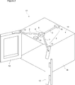
- Figure 1 is a perspective view of an oven and a linkage mechanism with the doors in closed position.
- Figure 2 is a perspective view of an oven and a linkage mechanism with the doors in open position.
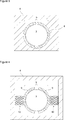
- Figure 3 is a schematic sectional view of the linear slide bearing consisting of the carriage block and the one-piece bearing bushing provided in the linkage mechanism.
- Figure 4 is a schematic sectional view of the carriage block and the linear slide bearing consisting of two bushing halves provided in the linkage mechanism.
- Figure 5 is a view from above of an oven and the linkage mechanism provided thereon with the doors in closed position.
- Figure 6 is a view from above of the rail provided in the linkage mechanism.
- Figure 7 is a view from above of an oven and the linkage mechanism provided thereon with the doors open 90 degrees.
- the linkage mechanism (1) is suitable to be used in ovens (17) comprising two side-by-side French style doors (12) connected to the front surfaces of the opposite left and right vertical edges of a body (11) so as to be pivotable about the vertical axis by means of hinges (13), and is mounted on a horizontal plane (14) on the upper or the lower wall of the body (11).
- the linkage mechanism (1) enables both doors (12) to be opened and closed simultaneously by a user moving only one of the doors (12).
- the linkage mechanism (1) of the invention comprises - two link arms (2) symmetrically connected by their front ends to the doors (12) so as to be pivotable about the vertical axis, movable parallel to the horizontal plane (14), and extending from both doors (12) by converging to each other towards the rear edge of the horizontal plane (14), - a linear motion guide rail (3) (hereinafter referred to as ‘rail (3)’ in short) fixed on the horizontal plane (14) in parallel to the horizontal plane (14) by means of a front mounting plate (15) and a rear mounting plate (16), - a carriage block (4) to which the rear ends of the link arms (2) are connected so as to be pivotable about the vertical axis, moving on the rail (3) during opening and closing of the doors (12), and - a linear slide bearing (5) provided in the carriage block (4), enabling the carriage block (4) to be movably supported on the rail (3).
- the link arm (2) connected to the door (12) being opened or closed transmits its movement by means of the carriage block (4) to the other (second) link arm (2) and therefore to the other (second) door (12), thereby enabling both doors (12) to be opened or closed simultaneously.
- the linear slide bearing (5) significantly reduces the friction forces acting on the linkage mechanism (1). A user can open and close the doors (2) by utilizing very little force, thereby providing ease of use and silent operation.
- the linkage mechanism (1) comprises a linear slide bearing (5) consisting of a cylindrical rail (3) and a one-piece bearing bushing (6) of hollow cylindrical structure provided in the carriage block (4), made of a material with low friction coefficient, whose inner surface contacts all around the rail (3), enabling the carriage block (4) to slide on the rail (3).
- the bearing bushing (6) is preferably made of a plastic material, e.g. acetal (POM), Teflon (PTFE) or polyamide (PA), or may be made of bronze or a graphite added material with self-lubricating properties.
- a plastic material e.g. acetal (POM), Teflon (PTFE) or polyamide (PA), or may be made of bronze or a graphite added material with self-lubricating properties.
- the linkage mechanism (1) comprises a first bulge (7) provided at the rear portion of the rail (3), enabling temporarily stopping or “halting” the carriage block (4) and therefore the doors (12) connected to the link arms (2) when the doors (12) are being brought to the fully closed position and from the closed position to the open position.
- the linkage mechanism (1) comprises at least one second bulge (8) provided at the front portion of the rail (3), enabling temporarily stopping the carriage block (4) and therefore the doors (12) connected to the link arms (2) when the doors (12) are being brought to approximately 90 degrees opened position.
- the first bulge (7) and the second bulge(s) (8) are formed on the cylindrical rail (3) by means of a production method such as forging.
- the linkage mechanism (1) comprises a linear slide bearing (5) consisting of two split bushing halves (9), provided in the carriage block (4), enabling the carriage block (4) to be supported during its linear sliding motion on the rail (3) so as to be able to pass over the first bulge (7) and/or the second bulge (8), and contacting the opposite semi-cylindrical surfaces of the rail (3).
- the linkage mechanism (1) further comprises two compression springs (10) connected between the bushing halves (9) and the carriage block (4), enabling the bushing halves (9) to mutually apply pressure on the rail (3) surface with a determined force
- the compression springs (10) enable the carriage block (4) to be supported without gaps at all positions on the rail (3) and with a predetermined pressure force by pushing the bushing halves (9) towards each other.
- the carriage block (4) moves from front to back on the rail (3) and passes over the first bulge (7) reaching the bulge's inclined portion behind the bulge in the narrowing direction thanks to the linear slide bearing (5) having two bushing halves (9) and the compression springs (10).
- the inclination of the first bulge (7) in the narrowing direction towards the back forces the carriage block (4) to move towards the back side.
- the first bulge (7) backs up the closing force applied by the user, enabling the doors (12) to be sealingly closed.
- the carriage block (4) moves from back to front on the rail (3), passing over the first bulge (7) from back to front.
- the narrowing portion in front of the first bulge (7) backs up the forwards motion of the carriage block (4).
- the user easily opens both doors (12) by applying a little force to a single door (12).
- the carriage block (4) is halted by the second bulge (8).
- the halt enforced by the second bulge (8) at approximately 90 degrees opened position allows the user to check whether there is a unsafe obstacle for the doors (12) to be opened more than 90 degrees.
- linkage mechanism (1) of the invention is suitable to be used in domestic appliances such as refrigerators and furniture such as wardrobes comprising two French style side-by-side doors (12).
Landscapes
- Engineering & Computer Science (AREA)
- Chemical & Material Sciences (AREA)
- Combustion & Propulsion (AREA)
- Mechanical Engineering (AREA)
- General Engineering & Computer Science (AREA)
- Refrigerator Housings (AREA)
Abstract
The present invention relates to a linkage mechanism (1) suitable to be used in ovens (17) comprising two side-by-side French style doors (12) connected to the front surfaces of opposite left and right vertical edges of a body (11) so as to be pivotable about the vertical axis by means of hinges (13), mounted on a horizontal plane (14) on the upper or the lower wall of the body (11), enabling both doors (12) to be opened or closed simultaneously by a user moving only one of the doors (12), and comprising two link arms (2) symmetrically connected by their front ends to the doors (12) so as to be pivotable about the vertical axis, movable parallel to the horizontal plane (14), and extending from both doors (12) by converging to each other towards the rear edge of the horizontal plane (14). The linkage mechanism further comprises: - a rail (3) fixed on the horizontal plane (14) in parallel to the horizontal plane (14) by means of a front mounting plate (15) and a rear mounting plate (16), - a carriage block (4) to which the rear ends of the link arms (2) are connected, moving on the rail (3) during opening and closing of the doors (12), and by - a linear slide bearing (5) enabling the carriage block (4) to be movably supported on the rail (3).
Description
The present invention relates to a linkage mechanism suitable to be used particularly in an oven or in domestic appliances such as a refrigerator or in furniture such as a wardrobe, comprising French style doors positioned side-by-side.
Known oven doors are opened in up-down direction by being pivoted about the horizontal axis. The door of an oven is pulled outwards the body by being held from its upper portion, and is brought to the horizontal and fully open position by being pivoted about the hinges with horizontal rotational axis provided on its lower edge. When the kitchen environment where the oven is being used lacks sufficient space, the area occupied by the door in horizontal position may create a problem for the users. In such a case, a user has to stand at the side of the oven to access the cooking volume when the oven door is fully opened. In the state of the art, ovens have been provided to solve this problem, comprising French style doors opening and closing by being pivoted about the vertical axis. In such type of ovens, symmetrically configured doors are used positioned side-by-side on the left and right sides. When one of the two French style side-by-side doors is opened and closed by a user, the other door also opens and closes simultaneously. A user can thus open both doors of the oven by a single hand, and can place into the oven the tray with the food products to be cooked thereon. Said simultaneous motion of French style doors is realized by a linkage mechanism coupling two doors to each other. These advantages of the French style doors are accompanied with certain disadvantages. Such doors simultaneously closing by a linkage mechanism are unable to provide a complete sealing. Moreover, since a linkage mechanism consists of metal parts with rather high friction forces in between, a user has to apply a strong force to be able to open and close the doors and cannot control the motion of the doors sufficiently.
Patent applications no. US2007039605 (A1) and US2009145031 (A1) disclose door linkage systems used in ovens having French style doors.
Patent application no. US2010206289 (A1) discloses a locking system in an oven, used for doors moving interdependently by means of a linkage system.
The aim of the present invention is to realize a linkage mechanism suitable to be used particularly in an oven comprising French style side-by-side doors, enabling a user to open both doors by pulling a single door with little force and enabling the doors to be sealingly closed.
The linkage mechanism realized to achieve the aim of the present invention, is suitable to be used in ovens, domestic appliances such as refrigerators or furniture such as wardrobes comprising French style side-by-side doors, and is mounted on a horizontal axis on the upper wall or the lower wall of the body of the appliance/item on which it is used, and enables both doors to be opened and closed simultaneously by a user pulling or pushing only one of the doors. The linkage mechanism comprises two link arms connected to the doors, a carriage block to which the rear ends of the link arms are connected, and a rail on which the carriage block moves. The link arm connected to the door being opened or closed transmits its movement by means of the carriage block to the other link arm and therefore to the other door. The carriage block is supported by means of a linear slide bearing so as to be movable on the rail.
In an embodiment of the invention, the linear slide bearing is a bearing bushing made of a material with low friction coefficient such as plastic or bronze.
In another embodiment of the invention, the linkage mechanism comprises bulges provided proximate to the rear end and the front end of the rail, enabling the doors to be sealingly closed and to be halted when the doors are brought to approximately 90 degrees open position. In this embodiment, the carriage block is supported by two split bushing halves so as to be able to pass over the bulges on the rail. The busing halves mutually contact the rail surface by means of two compression springs.
The linkage mechanism realized to achieve the aims of the present invention is illustrated in the accompanying drawings, wherein:
Figure 1 is a perspective view of an oven and a linkage mechanism with the doors in closed position.
Figure 2 is a perspective view of an oven and a linkage mechanism with the doors in open position.
Figure 3 is a schematic sectional view of the linear slide bearing consisting of the carriage block and the one-piece bearing bushing provided in the linkage mechanism.
Figure 4 is a schematic sectional view of the carriage block and the linear slide bearing consisting of two bushing halves provided in the linkage mechanism.
Figure 5 is a view from above of an oven and the linkage mechanism provided thereon with the doors in closed position.
Figure 6 is a view from above of the rail provided in the linkage mechanism.
Figure 7 is a view from above of an oven and the linkage mechanism provided thereon with the doors open 90 degrees.
The elements in the figures are numbered individually and the correspondence of these numbers are given hereinafter.
- Linkage mechanism
- Link arm
- Rail
- Carriage block
- Linear slide bearing
- Bearing bushing
- First bulge
- Second bulge
- Bushing half
- Compression spring
- Body
- Door
- Hinge
- Horizontal plane
- Front mounting plate
- Rear mounting plate
- Oven
The linkage mechanism (1), is suitable to be used in ovens (17) comprising two side-by-side French style doors (12) connected to the front surfaces of the opposite left and right vertical edges of a body (11) so as to be pivotable about the vertical axis by means of hinges (13), and is mounted on a horizontal plane (14) on the upper or the lower wall of the body (11).
The linkage mechanism (1) enables both doors (12) to be opened and closed simultaneously by a user moving only one of the doors (12).
The linkage mechanism (1) of the invention comprises
- two link arms (2) symmetrically connected by their front ends to the doors (12) so as to be pivotable about the vertical axis, movable parallel to the horizontal plane (14), and extending from both doors (12) by converging to each other towards the rear edge of the horizontal plane (14),
- a linear motion guide rail (3) (hereinafter referred to as ‘rail (3)’ in short) fixed on the horizontal plane (14) in parallel to the horizontal plane (14) by means of a front mounting plate (15) and a rear mounting plate (16),
- a carriage block (4) to which the rear ends of the link arms (2) are connected so as to be pivotable about the vertical axis, moving on the rail (3) during opening and closing of the doors (12), and
- a linear slide bearing (5) provided in the carriage block (4), enabling the carriage block (4) to be movably supported on the rail (3).
- two link arms (2) symmetrically connected by their front ends to the doors (12) so as to be pivotable about the vertical axis, movable parallel to the horizontal plane (14), and extending from both doors (12) by converging to each other towards the rear edge of the horizontal plane (14),
- a linear motion guide rail (3) (hereinafter referred to as ‘rail (3)’ in short) fixed on the horizontal plane (14) in parallel to the horizontal plane (14) by means of a front mounting plate (15) and a rear mounting plate (16),
- a carriage block (4) to which the rear ends of the link arms (2) are connected so as to be pivotable about the vertical axis, moving on the rail (3) during opening and closing of the doors (12), and
- a linear slide bearing (5) provided in the carriage block (4), enabling the carriage block (4) to be movably supported on the rail (3).
The link arm (2) connected to the door (12) being opened or closed transmits its movement by means of the carriage block (4) to the other (second) link arm (2) and therefore to the other (second) door (12), thereby enabling both doors (12) to be opened or closed simultaneously. The linear slide bearing (5) significantly reduces the friction forces acting on the linkage mechanism (1). A user can open and close the doors (2) by utilizing very little force, thereby providing ease of use and silent operation.
In an embodiment of the invention, the linkage mechanism (1) comprises a linear slide bearing (5) consisting of a cylindrical rail (3) and a one-piece bearing bushing (6) of hollow cylindrical structure provided in the carriage block (4), made of a material with low friction coefficient, whose inner surface contacts all around the rail (3), enabling the carriage block (4) to slide on the rail (3).
The bearing bushing (6) is preferably made of a plastic material, e.g. acetal (POM), Teflon (PTFE) or polyamide (PA), or may be made of bronze or a graphite added material with self-lubricating properties.
In an embodiment of the invention, the linkage mechanism (1) comprises a first bulge (7) provided at the rear portion of the rail (3), enabling temporarily stopping or "halting" the carriage block (4) and therefore the doors (12) connected to the link arms (2) when the doors (12) are being brought to the fully closed position and from the closed position to the open position.
In an embodiment of the invention, the linkage mechanism (1) comprises at least one second bulge (8) provided at the front portion of the rail (3), enabling temporarily stopping the carriage block (4) and therefore the doors (12) connected to the link arms (2) when the doors (12) are being brought to approximately 90 degrees opened position.
The first bulge (7) and the second bulge(s) (8) are formed on the cylindrical rail (3) by means of a production method such as forging.
In the two embodiments described above, the linkage mechanism (1) comprises a linear slide bearing (5) consisting of two split bushing halves (9), provided in the carriage block (4), enabling the carriage block (4) to be supported during its linear sliding motion on the rail (3) so as to be able to pass over the first bulge (7) and/or the second bulge (8), and contacting the opposite semi-cylindrical surfaces of the rail (3). The linkage mechanism (1) further comprises two compression springs (10) connected between the bushing halves (9) and the carriage block (4), enabling the bushing halves (9) to mutually apply pressure on the rail (3) surface with a determined force
On the portions of the rail (3) with larger diameter where the first bulge (7) and/or the second bulge (8) are disposed and the other portions of the rail (3) with nominal diameter, the compression springs (10) enable the carriage block (4) to be supported without gaps at all positions on the rail (3) and with a predetermined pressure force by pushing the bushing halves (9) towards each other.
During closing of the doors (12), the carriage block (4) moves from front to back on the rail (3) and passes over the first bulge (7) reaching the bulge's inclined portion behind the bulge in the narrowing direction thanks to the linear slide bearing (5) having two bushing halves (9) and the compression springs (10). The inclination of the first bulge (7) in the narrowing direction towards the back, forces the carriage block (4) to move towards the back side. The first bulge (7) backs up the closing force applied by the user, enabling the doors (12) to be sealingly closed. When the doors (12) are being opened, the carriage block (4) moves from back to front on the rail (3), passing over the first bulge (7) from back to front. The narrowing portion in front of the first bulge (7) backs up the forwards motion of the carriage block (4). The user easily opens both doors (12) by applying a little force to a single door (12). When the doors (12) are brought to approximately 90 degrees opened position, the carriage block (4) is halted by the second bulge (8). When the doors (12) are being brought to the fully opened position, the halt enforced by the second bulge (8) at approximately 90 degrees opened position, allows the user to check whether there is a unsafe obstacle for the doors (12) to be opened more than 90 degrees. The user opens the doors (12) fully when he/she does not observe any obstacles.
In addition, the linkage mechanism (1) of the invention is suitable to be used in domestic appliances such as refrigerators and furniture such as wardrobes comprising two French style side-by-side doors (12).
Claims (9)
- A linkage mechanism (1) suitable to be used in ovens (17) comprising two side-by-side French style doors (12) connected to the front surfaces of opposite left and right vertical edges of a body (11) so as to be pivotable about the vertical axis by means of hinges (13), mounted on a horizontal plane (14) on the upper or the lower wall of the body (11), enabling both doors (12) to be opened and closed simultaneously by a user moving only one of the doors (12), comprising- two link arms (2) symmetrically connected by their front ends to the doors (12) so as to be pivotable about the vertical axis, movable parallel to the horizontal plane (14), and extending from both doors (12) by converging to each other towards the rear edge of the horizontal plane (14), characterized by- a rail (3) fixed on the horizontal plane (14) in parallel to the horizontal plane (14) by means of a front mounting plate (15) and a rear mounting plate (16),- a carriage block (4) to which the rear ends of the link arms (2) are connected, moving on the rail (3) during opening and closing of the doors (12), and by- a linear slide bearing (5) enabling the carriage block (4) to be movably supported on the rail (3).
- A linkage mechanism (1) according to claim 1, characterized by the linear slide bearing (5) consisting of a cylindrical rail (3) and a one-piece bearing bushing (6) of hollow cylindrical structure provided in the carriage block (4), made of a material with low friction coefficient, whose inner surface contacts all around the rail (3).
- A linkage mechanism (1) according to claim 2, characterized by a bearing bushing (6) made of plastic material.
- A linkage mechanism (1) according to claim 1, characterized by a first bulge (7) provided at the rear portion of the rail (3), enabling the carriage block (4) to be temporarily stopped when the doors (12) are being brought to the fully closed position and from the closed position to the open position.
- A linkage mechanism (1) according to claim 1, characterized by at least one second bulge (8) provided at the front portion of the rail (3), enabling the carriage block (4) to be temporarily stopped when the doors (12) are being brought to approximately 90 degrees opened position.
- A linkage mechanism (1) according to claim 4 or 5, characterized by the linear slide bearing (5) consisting of two split bushing halves (9), provided in the carriage block (4), enabling the carriage block (4) to be supported on the rail (3) so as to be able to pass over the first bulge (7) and/or the second bulge (8), and contacting the opposite semi-cylindrical surfaces of the rail (3).
- A linkage mechanism (1) according to claim 6, characterized by two compression springs (10) connected between the bushing halves (9) and the carriage block (4), enabling the bushing halves (9) to mutually apply pressure on the rail (3) surface with a determined force.
- A refrigerator comprising two doors side-by-side, characterized by a linkage mechanism (1) according to claim 1.
- A wardrobe comprising two doors side-by-side, characterized by a linkage mechanism (1) according to claim 1.
Applications Claiming Priority (2)
| Application Number | Priority Date | Filing Date | Title |
|---|---|---|---|
| TRA2018/03054 | 2018-03-02 | ||
| TR201803054 | 2018-03-02 |
Publications (1)
| Publication Number | Publication Date |
|---|---|
| WO2019166363A1 true WO2019166363A1 (en) | 2019-09-06 |
Family
ID=65628751
Family Applications (1)
| Application Number | Title | Priority Date | Filing Date |
|---|---|---|---|
| PCT/EP2019/054571 Ceased WO2019166363A1 (en) | 2018-03-02 | 2019-02-25 | Linkage mechanism suitable to be used in an oven comprising french style doors |
Country Status (1)
| Country | Link |
|---|---|
| WO (1) | WO2019166363A1 (en) |
Cited By (1)
| Publication number | Priority date | Publication date | Assignee | Title |
|---|---|---|---|---|
| CN115057100A (en) * | 2021-12-27 | 2022-09-16 | 山东品正金属制品有限公司 | Adjustable self-discharging turnover box with movable bottom plate |
Citations (12)
| Publication number | Priority date | Publication date | Assignee | Title |
|---|---|---|---|---|
| US835984A (en) * | 1906-08-07 | 1906-11-13 | William B Reis | Controlling device for double doors. |
| US1886999A (en) * | 1931-08-06 | 1932-11-08 | Wilson Amanda Edsen | Door control mechanism |
| US2707225A (en) * | 1951-10-13 | 1955-04-26 | Gen Motors Corp | Electric range |
| US2708709A (en) * | 1954-03-16 | 1955-05-17 | Gen Motors Corp | Domestic appliance |
| US3216776A (en) * | 1963-10-22 | 1965-11-09 | Gen Electric | Refrigerator cabinet |
| DE4204812A1 (en) * | 1992-02-18 | 1993-08-26 | Daimler Benz Ag | Ball arrest device for road vehicle door fitting - has guide bush for slide guiding the arresting means in which screw pressure spring is coaxially arranged |
| DE20100057U1 (en) * | 2000-01-17 | 2001-04-26 | Julius Blum Ges.m.b.H., Höchst | Cabinet-shaped furniture with two doors |
| US20070039605A1 (en) | 2005-08-18 | 2007-02-22 | Maytag Corp. | Door linkage system for an oven having french-style doors |
| US20090145031A1 (en) | 2007-12-06 | 2009-06-11 | Collene James J | French door hinge system for oven |
| US20100206289A1 (en) | 2005-08-18 | 2010-08-19 | Whirlpool Corporation | Door locking mechanism for an oven having french-style doors |
| WO2017157041A1 (en) * | 2016-03-18 | 2017-09-21 | 比亚迪股份有限公司 | Door limiter for vehicle and control box thereof, and vehicle having such door limiter |
| DE102016010317A1 (en) * | 2016-08-25 | 2018-03-01 | GM Global Technology Operations LLC (n. d. Ges. d. Staates Delaware) | Door stopper |
-
2019
- 2019-02-25 WO PCT/EP2019/054571 patent/WO2019166363A1/en not_active Ceased
Patent Citations (12)
| Publication number | Priority date | Publication date | Assignee | Title |
|---|---|---|---|---|
| US835984A (en) * | 1906-08-07 | 1906-11-13 | William B Reis | Controlling device for double doors. |
| US1886999A (en) * | 1931-08-06 | 1932-11-08 | Wilson Amanda Edsen | Door control mechanism |
| US2707225A (en) * | 1951-10-13 | 1955-04-26 | Gen Motors Corp | Electric range |
| US2708709A (en) * | 1954-03-16 | 1955-05-17 | Gen Motors Corp | Domestic appliance |
| US3216776A (en) * | 1963-10-22 | 1965-11-09 | Gen Electric | Refrigerator cabinet |
| DE4204812A1 (en) * | 1992-02-18 | 1993-08-26 | Daimler Benz Ag | Ball arrest device for road vehicle door fitting - has guide bush for slide guiding the arresting means in which screw pressure spring is coaxially arranged |
| DE20100057U1 (en) * | 2000-01-17 | 2001-04-26 | Julius Blum Ges.m.b.H., Höchst | Cabinet-shaped furniture with two doors |
| US20070039605A1 (en) | 2005-08-18 | 2007-02-22 | Maytag Corp. | Door linkage system for an oven having french-style doors |
| US20100206289A1 (en) | 2005-08-18 | 2010-08-19 | Whirlpool Corporation | Door locking mechanism for an oven having french-style doors |
| US20090145031A1 (en) | 2007-12-06 | 2009-06-11 | Collene James J | French door hinge system for oven |
| WO2017157041A1 (en) * | 2016-03-18 | 2017-09-21 | 比亚迪股份有限公司 | Door limiter for vehicle and control box thereof, and vehicle having such door limiter |
| DE102016010317A1 (en) * | 2016-08-25 | 2018-03-01 | GM Global Technology Operations LLC (n. d. Ges. d. Staates Delaware) | Door stopper |
Cited By (1)
| Publication number | Priority date | Publication date | Assignee | Title |
|---|---|---|---|---|
| CN115057100A (en) * | 2021-12-27 | 2022-09-16 | 山东品正金属制品有限公司 | Adjustable self-discharging turnover box with movable bottom plate |
Similar Documents
| Publication | Publication Date | Title |
|---|---|---|
| US10731865B2 (en) | Domestic appliance including door mounted through articulated hinge mechanism | |
| AU2020317659B2 (en) | Refrigerator | |
| US12049775B2 (en) | Refrigerator | |
| CN112878833B (en) | Hinge assembly and appliance provided with same | |
| US8226180B2 (en) | Door coupling system | |
| JP6932308B2 (en) | Damper device | |
| US9777523B2 (en) | Home appliance having movable door handle | |
| US3955865A (en) | Oven door counterbalance system | |
| CN114258449B (en) | Hinge with damper for controlled closing and opening of door | |
| US7814897B2 (en) | Door linkage system for an oven having french-style doors | |
| US20220260302A1 (en) | Refrigerator | |
| EP2534325B1 (en) | Hinge mechanism for a home appliance providing door motion in a non-circular path | |
| US11060333B2 (en) | Hinge assembly for a home appliance and method of assembling | |
| US20160333624A1 (en) | Home appliance having movable handle | |
| CN105960500A (en) | Bearing arrangement for door | |
| WO2019166363A1 (en) | Linkage mechanism suitable to be used in an oven comprising french style doors | |
| EP3621507B1 (en) | Hinge for home appliance | |
| EP0864719A1 (en) | System for opening and closing doors in furniture, rooms and the like | |
| EP2886762A1 (en) | Multi-link hinge | |
| CN108350715B (en) | Hinge device with ventilation opening possibility | |
| CN217461814U (en) | Hinge mechanism and refrigerating device | |
| CN112739881B (en) | Hinge device for household appliances and furnishings with terminal speed attenuation | |
| WO2019166358A1 (en) | An oven comprising french style doors | |
| EP0520963B1 (en) | A device for slidably-partingly mounting a lining panel on the door of an embedded household appliance | |
| US12474062B2 (en) | Home appliance |
Legal Events
| Date | Code | Title | Description |
|---|---|---|---|
| 121 | Ep: the epo has been informed by wipo that ep was designated in this application |
Ref document number: 19708264 Country of ref document: EP Kind code of ref document: A1 |
|
| NENP | Non-entry into the national phase |
Ref country code: DE |
|
| 122 | Ep: pct application non-entry in european phase |
Ref document number: 19708264 Country of ref document: EP Kind code of ref document: A1 |