WO2019163977A1 - Weld operation measurement system - Google Patents
Weld operation measurement system Download PDFInfo
- Publication number
- WO2019163977A1 WO2019163977A1 PCT/JP2019/006954 JP2019006954W WO2019163977A1 WO 2019163977 A1 WO2019163977 A1 WO 2019163977A1 JP 2019006954 W JP2019006954 W JP 2019006954W WO 2019163977 A1 WO2019163977 A1 WO 2019163977A1
- Authority
- WO
- WIPO (PCT)
- Prior art keywords
- welding
- torch
- data
- work
- measurement system
- Prior art date
Links
Images


Classifications
-
- B—PERFORMING OPERATIONS; TRANSPORTING
- B23—MACHINE TOOLS; METAL-WORKING NOT OTHERWISE PROVIDED FOR
- B23K—SOLDERING OR UNSOLDERING; WELDING; CLADDING OR PLATING BY SOLDERING OR WELDING; CUTTING BY APPLYING HEAT LOCALLY, e.g. FLAME CUTTING; WORKING BY LASER BEAM
- B23K9/00—Arc welding or cutting
- B23K9/095—Monitoring or automatic control of welding parameters
- B23K9/0956—Monitoring or automatic control of welding parameters using sensing means, e.g. optical
-
- B—PERFORMING OPERATIONS; TRANSPORTING
- B23—MACHINE TOOLS; METAL-WORKING NOT OTHERWISE PROVIDED FOR
- B23K—SOLDERING OR UNSOLDERING; WELDING; CLADDING OR PLATING BY SOLDERING OR WELDING; CUTTING BY APPLYING HEAT LOCALLY, e.g. FLAME CUTTING; WORKING BY LASER BEAM
- B23K31/00—Processes relevant to this subclass, specially adapted for particular articles or purposes, but not covered by only one of the preceding main groups
- B23K31/12—Processes relevant to this subclass, specially adapted for particular articles or purposes, but not covered by only one of the preceding main groups relating to investigating the properties, e.g. the weldability, of materials
- B23K31/125—Weld quality monitoring
-
- B—PERFORMING OPERATIONS; TRANSPORTING
- B23—MACHINE TOOLS; METAL-WORKING NOT OTHERWISE PROVIDED FOR
- B23K—SOLDERING OR UNSOLDERING; WELDING; CLADDING OR PLATING BY SOLDERING OR WELDING; CUTTING BY APPLYING HEAT LOCALLY, e.g. FLAME CUTTING; WORKING BY LASER BEAM
- B23K9/00—Arc welding or cutting
- B23K9/02—Seam welding; Backing means; Inserts
-
- B—PERFORMING OPERATIONS; TRANSPORTING
- B23—MACHINE TOOLS; METAL-WORKING NOT OTHERWISE PROVIDED FOR
- B23K—SOLDERING OR UNSOLDERING; WELDING; CLADDING OR PLATING BY SOLDERING OR WELDING; CUTTING BY APPLYING HEAT LOCALLY, e.g. FLAME CUTTING; WORKING BY LASER BEAM
- B23K9/00—Arc welding or cutting
- B23K9/095—Monitoring or automatic control of welding parameters
- B23K9/0953—Monitoring or automatic control of welding parameters using computing means
-
- B—PERFORMING OPERATIONS; TRANSPORTING
- B23—MACHINE TOOLS; METAL-WORKING NOT OTHERWISE PROVIDED FOR
- B23K—SOLDERING OR UNSOLDERING; WELDING; CLADDING OR PLATING BY SOLDERING OR WELDING; CUTTING BY APPLYING HEAT LOCALLY, e.g. FLAME CUTTING; WORKING BY LASER BEAM
- B23K9/00—Arc welding or cutting
- B23K9/16—Arc welding or cutting making use of shielding gas
- B23K9/167—Arc welding or cutting making use of shielding gas and of a non-consumable electrode
-
- B—PERFORMING OPERATIONS; TRANSPORTING
- B23—MACHINE TOOLS; METAL-WORKING NOT OTHERWISE PROVIDED FOR
- B23K—SOLDERING OR UNSOLDERING; WELDING; CLADDING OR PLATING BY SOLDERING OR WELDING; CUTTING BY APPLYING HEAT LOCALLY, e.g. FLAME CUTTING; WORKING BY LASER BEAM
- B23K9/00—Arc welding or cutting
- B23K9/16—Arc welding or cutting making use of shielding gas
- B23K9/173—Arc welding or cutting making use of shielding gas and of a consumable electrode
-
- B—PERFORMING OPERATIONS; TRANSPORTING
- B23—MACHINE TOOLS; METAL-WORKING NOT OTHERWISE PROVIDED FOR
- B23K—SOLDERING OR UNSOLDERING; WELDING; CLADDING OR PLATING BY SOLDERING OR WELDING; CUTTING BY APPLYING HEAT LOCALLY, e.g. FLAME CUTTING; WORKING BY LASER BEAM
- B23K9/00—Arc welding or cutting
- B23K9/32—Accessories
-
- G—PHYSICS
- G09—EDUCATION; CRYPTOGRAPHY; DISPLAY; ADVERTISING; SEALS
- G09B—EDUCATIONAL OR DEMONSTRATION APPLIANCES; APPLIANCES FOR TEACHING, OR COMMUNICATING WITH, THE BLIND, DEAF OR MUTE; MODELS; PLANETARIA; GLOBES; MAPS; DIAGRAMS
- G09B19/00—Teaching not covered by other main groups of this subclass
- G09B19/24—Use of tools
-
- G—PHYSICS
- G09—EDUCATION; CRYPTOGRAPHY; DISPLAY; ADVERTISING; SEALS
- G09B—EDUCATIONAL OR DEMONSTRATION APPLIANCES; APPLIANCES FOR TEACHING, OR COMMUNICATING WITH, THE BLIND, DEAF OR MUTE; MODELS; PLANETARIA; GLOBES; MAPS; DIAGRAMS
- G09B9/00—Simulators for teaching or training purposes
Definitions
- the present invention relates to a welding operation measuring system for measuring a welding operation.
- Patent Document 1 measures the data related to the welding environment including the welding object and the behavior of the welder during the welding operation when manual welding is performed, and the feature value of the welding state during the welding operation is measured from the measured data.
- a method of managing welding quality by extracting and determining the quality of a hand-welded state and communicating the result to a welder is disclosed.
- Patent Document 1 describes managing the movement by acquiring the welder's movement in three-dimensional coordinates, but does not describe a detailed method such as a measurement principle.
- an object of the present invention is to provide a welding operation measurement system that can accurately measure the positional relationship between a welding object and a welder and obtains accurate three-dimensional coordinate data of the shape of a workpiece. .
- a welding motion measurement system of the present invention measures light reflected from a light irradiation unit that irradiates light and a marker attached to a work or torch that reflects the irradiated light.
- 3D coordinate measurement unit that calculates 3D coordinate data of workpiece and torch, and coordinate the workpiece shape based on the input workpiece 3D graphic data and 3D coordinate data, And a calculation unit to be generated.
- the light irradiator may use either one that irradiates light having a predetermined wavelength or one that irradiates light having a predetermined wavelength region. Moreover, you may use the marker which light-emits attached to the workpiece
- a filter for extracting light of a specific wavelength is provided, and the three-dimensional coordinate measurement unit specifies the light reflected from the marker. It is preferable to use one that measures light of a wavelength.
- FIG. 1 is an overall view showing an embodiment of a welding work measurement system according to an embodiment of the present invention. It is an enlarged view of the torch periphery which concerns on the Example of this invention. It is an enlarged view of the torch concerning the example of the present invention. It is a schematic diagram which shows an example of the acquisition method of the coordinate data of the welding target object concerning the Example of this invention. It is a figure which shows an example of the marker coordinate data of the welding target object which concerns on the Example of this invention. It is a figure which shows the measurement result of the welding operation data in welding time or a welding position. It is a figure which shows the other Example (quality control system) of the welding work measuring system which concerns on the Example of this invention.
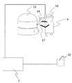
- FIG. 1 shows an overall view of a welding work measurement system in the first embodiment.
- the control unit (control device) 1 includes, for example, an arithmetic processing device (for example, a CPU), a storage device (for example, a semiconductor memory such as a ROM and a RAM, an HDD, etc.) that stores programs and data executed by the arithmetic processing device. It is a magnetic storage device, which corresponds to a “storage unit” described later), and a computer having a display device (for example, a monitor or a touch panel) that displays a calculation result of the calculation processing device.
- arithmetic processing device for example, a CPU
- a storage device for example, a semiconductor memory such as a ROM and a RAM, an HDD, etc.
- a computer having a display device (for example, a monitor or a touch panel) that displays a calculation result of the calculation processing device.
- Marker measurement cameras 2 a, 2 b, 2 c, 2 d, and 2 e that are light irradiators are arranged around the welder 4 and the welding object 7.
- the marker measurement cameras 2a, 2b, 2c, 2d, and 2e can set and irradiate light having a wavelength of 350 nm to 11 ⁇ m so as to avoid the wavelength of light during arc welding. In this embodiment, light of 850 nm is irradiated.
- the marker 3 is affixed to the welding object 7 (work 18), the torch 6, the welder 4, the light shielding surface 5, the filler material 19, and the like, and may reflect light or emit light.
- a marker to which a paint that reflects light is applied is used.
- it is sufficient that at least the marker is provided on the torch 6 and the welding object 7, and more detailed coordinate data is obtained by providing the marker on the welder 4, the light shielding surface 5, the filler material 19, and the like. It becomes possible.
- the marker measurement cameras 2a, 2b, 2c, 2d, 2e, the current / voltage measurement device 9, and the temperature / humidity / wind force measurement device 10 are connected to the control unit 1, and the operation of each measurement device is controlled by the control unit 1.
- the measured torch average moving speed, torch height, weaving conditions, torch angle, filler supply amount, elbow angle with torch, head position, etc., working data, current value, voltage value, temperature Environmental data such as humidity and wind power is sent to the control unit 1 and stored as accumulated data in a storage unit in the control unit 1.
- the control unit 1 has a function of displaying measured data.
- FIG. 2A shows an enlarged view around the torch 6, and FIG. 2B shows an enlarged view of the torch 6.
- a material that absorbs light of 850 nm, which is a predetermined wavelength, here an absorption film 11 is attached to the torch 6.
- a plurality of markers 3 are attached on the absorption film 11, and light from the marker measurement cameras 2 a, 2 b, 2 c, 2 d, 2 e is reflected by the marker 3, and an accurate position of the marker 3 is measured.
- Light emitted during arc welding includes light of 850 nm, and the light is reflected from a place other than the marker 3 and measured.
- a measurement start signal is sent from the control unit 1 to each measuring device (marker measuring camera which is a light irradiation device, current / voltage measuring device 9, temperature / humidity / wind force measuring device 10). Measurement is started. As described above, the measured accumulated data is sequentially sent to the control unit 1 and recorded in the storage unit.
- the storage unit also stores three-dimensional graphic data, which will be described later, which is input three-dimensional CAD data, and calculated three-dimensional coordinate data. Although the storage unit is described as being provided in the control unit 1, the storage unit may be provided outside the control unit 1.
- FIG. 3 shows a schematic diagram of a method for acquiring the coordinate data of the welding object 7 from the three-dimensional drawing data and the coordinate data of the marker 3 pasted on the welding object 7.
- the control unit 1 reflects the light irradiated by the marker measurement cameras 2a, 2b, 2c, 2d, and 2e, which are light irradiation devices, from the welding object 7 (work 18) and the marker 3 attached to the torch 6.
- the reflected light is measured, the three-dimensional coordinate measuring unit 21 for calculating the three-dimensional coordinate data of the workpiece 18 and the torch 6, and the shape of the workpiece 18 is coordinated based on the three-dimensional graphic data and the three-dimensional coordinate data.
- an arithmetic unit 22 that generates coordinate data of 18 shapes.
- the calculation unit 22 matches the input three-dimensional graphic data and three-dimensional coordinate data of the workpiece 18 and calculates a deviation amount. Based on the calculated deviation amount, the shape of the workpiece 18 is calculated.
- the three-dimensional coordinate measuring unit 21, the deviation amount calculating unit 23, and the correcting unit 24 indicate functions of a program executed by the arithmetic processing device of the control unit 1 that is a computer. Details will be described below.
- the three-dimensional drawing data 12 of the welding object 7 is three-dimensional CAD data stored or input in advance, and is the marker coordinate data 13a, 13b, 13c, 13d, 13e, 13f, and 13g of the welding object 7.
- a certain three-dimensional coordinate data is the position coordinate data of each marker 3 shown in FIG. 4 measured by the marker measurement cameras 2a, 2b, 2c, 2d, and 2e, and is XYZ based on a predetermined position.
- the control unit 1 has a database which is a storage unit in which the 3D drawing data 12 of the welding object 3 is stored in advance, and the position of the marker 3 pasted on the 3D drawing data 12 and the welding object 3 is indicated.
- the marker coordinate data 13a, 13b, 13c, 13d, 13e, 13f, and 13g By matching the marker coordinate data 13a, 13b, 13c, 13d, 13e, 13f, and 13g with the deviation amount calculation unit 23 of the control unit 1, the marker coordinate data 13a, 13b, 13c, 13d, 13e, 13f, and 13g with the deviation amount calculation unit 23 of the control unit 1, the marker coordinate data 13a, 13b, 13c, 13d, 13e, 13f, and 13g.
- the correction unit 24 uses the matched data, that is, the deviation amount (difference) data between the three-dimensional drawing data 12 and the marker coordinate data 13a, 13b, 13c, 13d, 13e, 13f, and 13g. It is possible to predict the amount, offset the torch position by a predetermined ideal torch operation, and present it to the welding operator.
- the measurement result (positional relationship) of welding work data at the welding time and welding position as shown in FIG. 5 can be calculated.
- the control unit 1 can calculate the position, velocity, angle, locus, acceleration, angular velocity, and the like from the coordinate data that can be acquired from each marker. That is, it is possible to acquire a welding operation of a skilled person and a welding operation of a beginner as data, and the welding operation can be quantitatively evaluated.
- the feed amount of the filler material, the movement of the torch 6 in the welding progress direction, the deformation amount of the workpiece, the right The elbow angle was calculated. It was confirmed from the calculated feed amount of the filler material and the movement of the torch 6 in the welding progress direction that the filler material and the torch have a periodic operation pattern that repeats stationary and moving.
- the angle of the right elbow also increased in conjunction with the torch operation.
- the amount of deformation can be offset to the torch coordinate at the time of measurement of the next welding pass, and the relative position of the torch 6 with respect to the workpiece can be measured with high accuracy.
- the welding work measurement system of the present embodiment can accurately measure the positional relationship between the workpiece that is the welding object and the torch with the marker held by the welder, that is, the positional relationship between the welding object and the welder. It is possible to provide a welding motion measurement system that acquires three-dimensional coordinate data of an accurate workpiece shape.
- the semi-automatic welding has been described in the present embodiment, it is possible to measure similarly by TIG welding or the like, and even when using a filler metal, it can be similarly measured by attaching a marker to the filler metal.
- the marker is recognized by irradiating light having a predetermined wavelength (850 nm) from the light irradiation unit, but a light source having a wide wavelength range (predetermined wavelength region) is used as the light irradiation unit. May be.
- the three-dimensional coordinate measurement unit includes a filter that extracts light of a specific wavelength from the reflected light, and can measure light of a specific wavelength among the light reflected from the marker attached to the workpiece or the torch. preferable.
- a marker that emits light instead of a marker that reflects light
- either a marker that emits light of a predetermined wavelength or a marker that emits light having a wide wavelength range (predetermined wavelength range) is used. You can also choose.
- the latter marker having a wide wavelength range it is preferable to use a filter that extracts light of a specific wavelength in the same manner as the reflective marker.
- the marker may be provided with a filter function that reflects light of a specific wavelength.
- FIG. 6 shows an overall view when the welding work measurement system of Example 1 is used in a quality control system.
- Work data such as welding operation data, welding state data, welding environment data, and weld quality data acquired in the past are stored in advance, and welding operation data and welding newly measured by the measurement unit
- the quality determination unit determines the quality of the welded part by comparing with work data such as state data and welding environment data. In this quality judgment section, the work level of the welder can also be evaluated.
- the welding operation data may be measured by a global positioning system, an indoor global positioning system, a stereo camera, or the like in addition to the acceleration / angular velocity / geomagnetic measurement device such as the inertial sensor 14 described above.
- the measured marker coordinate data accumulated in the storage unit in the configuration of the first embodiment, the torch height, the welding time, and the welding as shown in FIG. Using the position data, the angle of the elbow with the torch (the angle of the right elbow in FIG. 5) and the accumulated data such as the welding time and welding position data, the measured torch height, welding time, welding position data, The right elbow angle is compared with the welding time and welding position data, and the results are used for quality control. This will be described below.
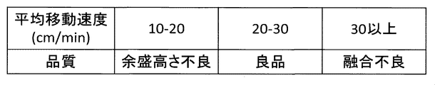
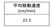
- FIG. 7A shows the relationship of quality to the average moving speed of the torch
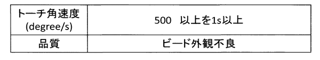
- FIG. 7B shows the relationship of quality to the angular velocity of the torch.
- the average moving speed (welding speed) of the torch is good if it is about 20-30 cm / min, and if the torch angular speed is kept at 500 degrees / s or more for 1 second or more, the bead appearance becomes poor.
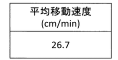
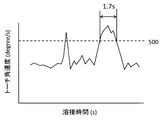
- the results of measurement during welding are shown in FIGS. 8A and 8B.
- the average moving speed was in a favorable range as shown in FIG.
- an inertial sensor is used as a sensor for measuring the torch operation, the present invention is not limited to this.
- FIG. 9 shows an overall view when the welding work measurement system of the first embodiment is used in an education system.
- Reference numeral 15 denotes a welding object simulation part
- 16 denotes a head-mounted display which is a display unit (display device)
- 17 denotes a simulation torch.
- the welding object simulation part 15 is the same as in Examples 1 and 2.
- the feature amount analyzed as having a strong correlation with quality in Example 1 can be trained without actually welding, and can be used as an educational system. .
- the inertial sensor 14 which is a work data measuring unit capable of measuring and calculating these feature amounts is attached to the torch as in the second embodiment (FIG. 6).
- the welding object simulation part 15 and the simulation torch 17 which are welding objects are provided with a pattern for camera recognition, and an imaging image (such as a camera) such as a camera is used to acquire a captured image.
- An imaging unit such as this camera may use a camera installed on the head mounted display 16.
- the imaging unit may be a stereo camera.
- a stereo camera By using a stereo camera, the positional relationship between the welding object simulated part 15 and the simulated torch 17 can be measured, that is, three-dimensional distance information and position information can be acquired.
- the marker provided on the torch has been measured with a camera to obtain accurate position information of the marker.
- a stereo camera can be used without using the marker.
- the positional relationship between the welding object simulated part 15 and the simulated torch 17 can be measured from the acquired three-dimensional distance data.
- the three-dimensional coordinate measurement unit 21 calculates the three-dimensional coordinate data of the welding target simulated part 15 and the simulated torch 17 that are the welding targets, As described in the first embodiment, the calculation unit 22 coordinates the shape of the welding target simulated part 15 based on the input three-dimensional graphic data and three-dimensional coordinate data of the welding target simulated part 15, and the welding target. Coordinate data of the shape of the simulated part 15 is generated.
- the simulated torch 17 has a welding start switch. If the switch is pressed, it is recognized as an energized state. If the torch tip is within a predetermined distance from the welding object simulation part 15 in the energized state, the arc is displayed on the head mounted display as a display unit, and accordingly, the molten pool is displayed. When the welder 4 moves the simulated torch 17, the arc and the molten pool move accordingly. Data stored in the past can be referred to by the control unit 1, and the arc, molten pool, welding sound, welding current and voltage corresponding to the operation of the torch can be reproduced.
- an arc or a molten pool corresponding to the operation of the torch based on the generated coordinate data of the shape of the simulated workpiece 15 and the work data stored in advance. It is possible to display a welding work image that reproduces the welding sound, welding current and voltage.
- FIG. 10A shows the training result of the average moving speed of the torch at the welding time
- FIG. 10B shows the training result of the angular speed of the torch at the welding time.
- the average moving speed of the torch and the angular speed of the torch satisfy an ideal predetermined range (experienced range of skilled person) stored in advance, and good welding can be obtained. It was a torch operation. In this way, the welder can perform welding training safely and without consuming a welding object for the torch operation to be trained.
- Accurate work data such as measured marker coordinate data, torch height and welding time and welding position data, right elbow angle and welding time and welding position data can be stored in this system. Therefore, it is possible to reference the training history and manage the skill level of the work.
- an education system is constructed using a virtual system, but it is also possible to train while actually welding using an actual welding object and torch.
- the welding operation can be accurately quantified, and the numerical data can be used in an education system and quality control to efficiently transfer skills and improve manufacturing quality. It is possible to provide a welding motion measurement system that can be improved and contribute to the reduction of the defect rate.
Abstract
Description
2a,2b,2c,2d,2e マーカ計測用カメラ
3 マーカ
4 溶接士
5 遮光面
6 トーチ
7 溶接対象物
8 溶接電源
9 溶接電流・電圧計測装置
10 温度・湿度・風力計測装置
11 吸収フィルム DESCRIPTION OF
Claims (16)
- 光を照射する光照射部と、
照射された前記光を反射する、ワークまたはトーチに取り付けられたマーカから反射した光を計測し、前記ワーク及びトーチの三次元座標データを算出する三次元座標計測部と、
入力されたワークの三次元図形データと前記三次元座標データに基づいて前記ワークの形状を座標化し、前記ワークの形状の座標データを生成する演算部と、
を有する溶接作業計測システム。 A light irradiation unit for irradiating light;
A three-dimensional coordinate measuring unit that reflects the irradiated light, measures light reflected from a marker attached to the workpiece or torch, and calculates three-dimensional coordinate data of the workpiece and torch;
A calculation unit that coordinates the shape of the workpiece based on the input three-dimensional graphic data of the workpiece and the three-dimensional coordinate data, and generates coordinate data of the shape of the workpiece;
Welding work measuring system having. - 請求項1記載の溶接作業システムであって、
前記光照射部は、所定の波長域を有する光を照射し、
前記三次元座標計測部は、特定の波長の光を抽出するフィルタを備え、前記マーカから反射した光のうち前記特定の波長の光を計測することを特徴とする溶接作業計測システム。 The welding work system according to claim 1,
The light irradiation unit irradiates light having a predetermined wavelength range,
The three-dimensional coordinate measurement unit includes a filter that extracts light of a specific wavelength, and measures the light of the specific wavelength out of the light reflected from the marker. - 請求項1記載の溶接作業システムであって、
前記光照射部は、所定の波長を有する光を照射することを特徴とする溶接作業計測システム。 The welding work system according to claim 1,
The welding operation measuring system, wherein the light irradiation unit irradiates light having a predetermined wavelength. - ワークまたはトーチに取り付けられた発光するマーカから照射された光を計測し、前記ワーク及びトーチの三次元座標データを算出する三次元座標計測部と、
入力されたワークの三次元図形データと前記三次元座標データに基づいて前記ワークの形状を座標化し、前記ワークの形状の座標データを生成する演算部と、
を有する溶接作業計測システム。 A three-dimensional coordinate measuring unit that measures light emitted from a marker that emits light attached to the workpiece or torch, and calculates three-dimensional coordinate data of the workpiece and torch;
A calculation unit that coordinates the shape of the workpiece based on the input three-dimensional graphic data of the workpiece and the three-dimensional coordinate data, and generates coordinate data of the shape of the workpiece;
Welding work measuring system having. - 請求項1記載の溶接作業システムであって、
前記演算部は、入力された前記ワークの三次元図形データと前記三次元座標データとをマッチングし、ズレ量を算出するズレ量算出部と、算出された前記ズレ量に基づいて、前記ワークの形状の座標データを補正する補正部と、を有する溶接作業計測システム。 The welding work system according to claim 1,
The calculation unit matches the input three-dimensional graphic data of the workpiece and the three-dimensional coordinate data, calculates a deviation amount, and based on the calculated deviation amount, And a correction unit that corrects the coordinate data of the shape. - 請求項1記載の溶接作業計測システムであって、
前記三次元座標計測部は、前記ワーク、前記トーチ、溶加材、及び作業者に取り付けられたマーカから反射した光を計測し、前記ワーク、前記トーチ、前記溶加材、及び前記作業者の三次元座標データを算出する、溶接作業計測システム。 The welding work measurement system according to claim 1,
The three-dimensional coordinate measuring unit measures light reflected from the work, the torch, the filler material, and a marker attached to the operator, and the workpiece, the torch, the filler material, and the operator's A welding work measurement system that calculates 3D coordinate data. - 請求項5記載の溶接作業計測システムであって、
前記補正部は、前記ズレ量に基づいて変形量を予測し、前記変形量に基づいて
前記演算部で演算された前記ワークの形状の前記座標データに基づいて、前記ワークの形状の座標データを補正する、溶接作業計測システム。 The welding work measurement system according to claim 5,
The correction unit predicts a deformation amount based on the shift amount, and based on the coordinate data of the shape of the workpiece calculated by the calculation unit based on the deformation amount, the coordinate data of the shape of the workpiece is obtained. The welding work measurement system to be corrected. - 請求項5記載の溶接作業計測システムであって、
前記補正部で補正された前記ワークの形状の座標データを表示する表示部を有する溶接作業計測システム。 The welding work measurement system according to claim 5,
A welding work measurement system having a display unit that displays coordinate data of the shape of the workpiece corrected by the correction unit. - 請求項1記載の溶接作業計測システムであって、
前記トーチは、前記光照射部から照射された前記光の前記所定の波長を吸収する物質が付与された、溶接作業計測システム。 The welding work measurement system according to claim 1,
The torch is a welding work measurement system to which a substance that absorbs the predetermined wavelength of the light irradiated from the light irradiation unit is applied. - 請求項1記載の溶接作業計測システムであって、
前記光照射部から照射された光の波長は350nmから11μmである溶接作業計測システム。 The welding work measurement system according to claim 1,
The welding work measurement system in which the wavelength of light emitted from the light irradiation unit is 350 nm to 11 μm. - 請求項1記載の溶接作業計測システムであって、
計測又は算出された前記ワーク及びトーチの三次元座標データを記憶する記憶部を有する溶接作業計測システム。 The welding work measurement system according to claim 1,
A welding work measurement system having a storage unit for storing the measured or calculated three-dimensional coordinate data of the work and torch. - 請求項1記載の溶接作業計測システムであって、
溶接時間又は溶接位置における作業データを計測する計測部と、
予め記憶された作業データと、前記計測部で計測された前記作業データと、に基づいて溶接部の品質を判定する品質判定部を有する溶接作業計測システム。 The welding work measurement system according to claim 1,
A measurement unit for measuring work data at the welding time or welding position;
A welding work measurement system including a quality determination unit that determines the quality of a welded part based on work data stored in advance and the work data measured by the measurement part. - 請求項12記載の溶接作業計測システムであって、
前記作業データとは、トーチの平均移動速度、トーチ高さ、ウィービング条件、トーチ角度、溶加材の供給量、トーチを持つひじの角度、頭の位置、の少なくとも1つのデータであり、
予め記憶された前記作業データとは過去に熟練者が溶接した際の作業データである、
溶接作業計測システム。 The welding work measurement system according to claim 12,
The work data is at least one data of an average moving speed of a torch, a torch height, a weaving condition, a torch angle, a supply amount of a filler metal, an angle of an elbow having a torch, and a head position.
The work data stored in advance is work data when an expert has welded in the past.
Welding work measurement system. - 模擬トーチと、
作業データを計測する作業データ計測部と、
溶接対象物と前記模擬トーチを撮像し、位置情報を取得する撮像部と、
前記撮像部で撮像した画像を表示する表示部と、
前記作業データ及び前記位置情報に基づいて前記溶接対象物及び前記トーチの三次元座標データを算出する三次元座標計測部と、
入力された溶接対象物の三次元図形データと前記三次元座標データに基づいて前記溶接対象物の形状を座標化し、前記溶接対象物の形状の座標データを生成する演算部と、を有し、
前記表示部は、生成された前記溶接対象物の形状の座標データと、予め記憶された作業データと、から生成された溶接作業の映像を表示する、溶接作業計測システム。 With a simulated torch,
A work data measuring unit for measuring work data;
An imaging unit that images the welding object and the simulated torch, and acquires position information;
A display unit for displaying an image captured by the imaging unit;
A three-dimensional coordinate measuring unit that calculates three-dimensional coordinate data of the welding object and the torch based on the work data and the position information;
A calculation unit that coordinates the shape of the welding object based on the three-dimensional graphic data of the input welding object and the three-dimensional coordinate data, and generates coordinate data of the shape of the welding object;
The said display part is a welding operation measurement system which displays the image | video of the welding operation produced | generated from the coordinate data of the shape of the said welding target object produced | generated, and the work data memorize | stored previously. - 請求項14記載の溶接作業計測システムであって、
前記作業データとは、トーチの平均移動速度、トーチ高さ、ウィービング条件、トーチ角度、溶加材の供給量、トーチを持つひじの角度、頭の位置、の少なくとも1つのデータであり、
予め記憶された前記作業データとは過去に熟練者が溶接した際の作業データである、
溶接作業計測システム。 The welding work measurement system according to claim 14,
The work data is at least one data of an average moving speed of a torch, a torch height, a weaving condition, a torch angle, a supply amount of a filler metal, an angle of an elbow having a torch, and a head position.
The work data stored in advance is work data when an expert has welded in the past.
Welding work measurement system. - 請求項14記載の溶接作業計測システムであって、
前記表示部に表示する前記溶接作業の映像とは、前記模擬トーチの動作に応じたアーク及び溶融池を再現する映像である、溶接作業計測システム。 The welding work measurement system according to claim 14,
The welding operation measurement system, wherein the welding operation image displayed on the display unit is an image reproducing an arc and a molten pool according to the operation of the simulated torch.
Priority Applications (5)
| Application Number | Priority Date | Filing Date | Title |
|---|---|---|---|
| US16/975,202 US20200391317A1 (en) | 2018-02-26 | 2019-02-25 | Welding operation measurement system |
| KR1020207023412A KR102447762B1 (en) | 2018-02-26 | 2019-02-25 | Welding motion measurement system |
| EP19756953.6A EP3744461A4 (en) | 2018-02-26 | 2019-02-25 | Weld operation measurement system |
| CN201980013460.9A CN111727100B (en) | 2018-02-26 | 2019-02-25 | Welding action measuring system |
| JP2020501077A JP7016401B2 (en) | 2018-02-26 | 2019-02-25 | Welding motion measurement system |
Applications Claiming Priority (2)
| Application Number | Priority Date | Filing Date | Title |
|---|---|---|---|
| JP2018-031501 | 2018-02-26 | ||
| JP2018031501 | 2018-02-26 |
Publications (1)
| Publication Number | Publication Date |
|---|---|
| WO2019163977A1 true WO2019163977A1 (en) | 2019-08-29 |
Family
ID=67688431
Family Applications (1)
| Application Number | Title | Priority Date | Filing Date |
|---|---|---|---|
| PCT/JP2019/006954 WO2019163977A1 (en) | 2018-02-26 | 2019-02-25 | Weld operation measurement system |
Country Status (6)
| Country | Link |
|---|---|
| US (1) | US20200391317A1 (en) |
| EP (1) | EP3744461A4 (en) |
| JP (1) | JP7016401B2 (en) |
| KR (1) | KR102447762B1 (en) |
| CN (1) | CN111727100B (en) |
| WO (1) | WO2019163977A1 (en) |
Cited By (2)
| Publication number | Priority date | Publication date | Assignee | Title |
|---|---|---|---|---|
| WO2021079414A1 (en) * | 2019-10-21 | 2021-04-29 | 株式会社日立システムズ | Knowledge information extraction system and knowledge information extraction method |
| JP2021065891A (en) * | 2019-10-18 | 2021-04-30 | 日立Geニュークリア・エナジー株式会社 | Welding speed calculation system, welding speed calculation method and welding speed calculation device |
Citations (6)
| Publication number | Priority date | Publication date | Assignee | Title |
|---|---|---|---|---|
| JP2001171140A (en) | 1999-12-17 | 2001-06-26 | Copyer Co Ltd | Ink-jet recording apparatus |
| JP2009500178A (en) * | 2005-07-15 | 2009-01-08 | フロニウス・インテルナツィオナール・ゲゼルシャフト・ミット・ベシュレンクテル・ハフツング | Welding method and system with position determination of welding torch |
| JP2011167756A (en) * | 2010-02-22 | 2011-09-01 | Hitachi Plant Technologies Ltd | Hand welding training system and method |
| JP2012254477A (en) * | 2011-06-10 | 2012-12-27 | Kobe Steel Ltd | Method and system for detecting welding anomaly |
| JP2013202618A (en) * | 2012-03-27 | 2013-10-07 | Daihen Corp | Welding system |
| JP2015225214A (en) * | 2014-05-28 | 2015-12-14 | 旭エレクトロニクス株式会社 | Simulation system |
Family Cites Families (17)
| Publication number | Priority date | Publication date | Assignee | Title |
|---|---|---|---|---|
| JPH09189513A (en) * | 1996-01-10 | 1997-07-22 | Kawasaki Heavy Ind Ltd | Marker gravity center measurement method and device |
| JPH11296218A (en) * | 1998-04-09 | 1999-10-29 | Hitachi Ltd | Method for off line teaching of robot |
| FI117426B (en) * | 2003-06-12 | 2006-10-13 | Aker Yards Oy | A method for controlling welding of a three-dimensional structure |
| JP2007152371A (en) * | 2005-12-01 | 2007-06-21 | Kanto Auto Works Ltd | Inspection system of welding spot position |
| DE102007008598A1 (en) * | 2007-02-19 | 2008-08-21 | Fraunhofer-Gesellschaft zur Förderung der angewandten Forschung e.V. | Automatic programming of robots to weld stapled profiles onto micropanels using digital image capture |
| CN101067905A (en) * | 2007-06-14 | 2007-11-07 | 中国石油天然气第一建设公司 | Special helmet device for welding analog operation |
| JP4963094B2 (en) * | 2007-09-11 | 2012-06-27 | 独立行政法人産業技術総合研究所 | Work support device |
| AT507021B1 (en) * | 2008-07-04 | 2010-04-15 | Fronius Int Gmbh | DEVICE FOR SIMULATING A WELDING PROCESS |
| JP2010234430A (en) | 2009-03-31 | 2010-10-21 | Hitachi Metals Ltd | Method of cutting runner for casting |
| US9221117B2 (en) * | 2009-07-08 | 2015-12-29 | Lincoln Global, Inc. | System for characterizing manual welding operations |
| US20160093233A1 (en) * | 2012-07-06 | 2016-03-31 | Lincoln Global, Inc. | System for characterizing manual welding operations on pipe and other curved structures |
| KR20140028201A (en) * | 2012-08-27 | 2014-03-10 | 권오수 | Spot welding monitoring system and its method |
| US9368045B2 (en) * | 2012-11-09 | 2016-06-14 | Illinois Tool Works Inc. | System and device for welding training |
| AT513828B1 (en) * | 2013-04-22 | 2014-08-15 | Fronius Int Gmbh | Method and apparatus for simulating an electrode welding process |
| US20160125762A1 (en) * | 2014-11-05 | 2016-05-05 | Illinois Tool Works Inc. | System and method for welding system clamp assembly |
| US10363632B2 (en) * | 2015-06-24 | 2019-07-30 | Illinois Tool Works Inc. | Time of flight camera for welding machine vision |
| US10438505B2 (en) * | 2015-08-12 | 2019-10-08 | Illinois Tool Works | Welding training system interface |
-
2019
- 2019-02-25 JP JP2020501077A patent/JP7016401B2/en active Active
- 2019-02-25 US US16/975,202 patent/US20200391317A1/en active Pending
- 2019-02-25 KR KR1020207023412A patent/KR102447762B1/en active IP Right Grant
- 2019-02-25 CN CN201980013460.9A patent/CN111727100B/en active Active
- 2019-02-25 EP EP19756953.6A patent/EP3744461A4/en active Pending
- 2019-02-25 WO PCT/JP2019/006954 patent/WO2019163977A1/en unknown
Patent Citations (6)
| Publication number | Priority date | Publication date | Assignee | Title |
|---|---|---|---|---|
| JP2001171140A (en) | 1999-12-17 | 2001-06-26 | Copyer Co Ltd | Ink-jet recording apparatus |
| JP2009500178A (en) * | 2005-07-15 | 2009-01-08 | フロニウス・インテルナツィオナール・ゲゼルシャフト・ミット・ベシュレンクテル・ハフツング | Welding method and system with position determination of welding torch |
| JP2011167756A (en) * | 2010-02-22 | 2011-09-01 | Hitachi Plant Technologies Ltd | Hand welding training system and method |
| JP2012254477A (en) * | 2011-06-10 | 2012-12-27 | Kobe Steel Ltd | Method and system for detecting welding anomaly |
| JP2013202618A (en) * | 2012-03-27 | 2013-10-07 | Daihen Corp | Welding system |
| JP2015225214A (en) * | 2014-05-28 | 2015-12-14 | 旭エレクトロニクス株式会社 | Simulation system |
Cited By (5)
| Publication number | Priority date | Publication date | Assignee | Title |
|---|---|---|---|---|
| JP2021065891A (en) * | 2019-10-18 | 2021-04-30 | 日立Geニュークリア・エナジー株式会社 | Welding speed calculation system, welding speed calculation method and welding speed calculation device |
| JP7333243B2 (en) | 2019-10-18 | 2023-08-24 | 日立Geニュークリア・エナジー株式会社 | Welding speed calculation system, welding speed calculation method, and welding speed calculation device |
| WO2021079414A1 (en) * | 2019-10-21 | 2021-04-29 | 株式会社日立システムズ | Knowledge information extraction system and knowledge information extraction method |
| JPWO2021079414A1 (en) * | 2019-10-21 | 2021-11-18 | 株式会社日立システムズ | Knowledge information extraction system and knowledge information extraction method |
| JP7052062B2 (en) | 2019-10-21 | 2022-04-11 | 株式会社日立システムズ | Knowledge information extraction system and knowledge information extraction method |
Also Published As
| Publication number | Publication date |
|---|---|
| KR102447762B1 (en) | 2022-09-27 |
| CN111727100B (en) | 2022-05-17 |
| US20200391317A1 (en) | 2020-12-17 |
| EP3744461A4 (en) | 2022-01-19 |
| JPWO2019163977A1 (en) | 2021-01-07 |
| EP3744461A1 (en) | 2020-12-02 |
| CN111727100A (en) | 2020-09-29 |
| KR20200106193A (en) | 2020-09-11 |
| JP7016401B2 (en) | 2022-02-04 |
Similar Documents
| Publication | Publication Date | Title |
|---|---|---|
| US10878591B2 (en) | Welding trainer utilizing a head up display to display simulated and real-world objects | |
| US10913125B2 (en) | Welding system providing visual and audio cues to a welding helmet with a display | |
| US11140939B2 (en) | Sensor assisted head mounted displays for welding | |
| CA2927243C (en) | Systems and methods for a weld training system | |
| EP3318360A1 (en) | Communication between a welding machine and a live welding training device | |
| US20160214198A1 (en) | Manual Tool Tracking and Guidance With Inertial Measurement Unit | |
| EP1435280A2 (en) | A method and a system for programming an industrial robot | |
| EP3247525B1 (en) | Manual tool tracking and guidance with inertial measurement unit | |
| JP5142775B2 (en) | Welding quality inspection method and apparatus | |
| KR20060127174A (en) | Method for planing an inspection path for determining areas that are to be inspected | |
| CN105209207A (en) | Virtual reality orbital pipe welding simulator and setup | |
| WO2019163977A1 (en) | Weld operation measurement system | |
| JP7261682B2 (en) | Welding work data storage device, welding work support system and welding robot control device | |
| JP2020035396A (en) | Sensing system, work system, presentation method of augmented reality image, and program | |
| JP2009069954A (en) | Operation support device | |
| JP5001330B2 (en) | Curved member measurement system and method | |
| JP7221792B2 (en) | Measurement program selection aid and measurement controller | |
| JP5018659B2 (en) | Work training system | |
| WO2020246080A1 (en) | Welding operation measurement system | |
| WO2020137122A1 (en) | Work assistance device and work assistance method | |
| JP2009034685A (en) | Automatic welding method and automatic welding apparatus | |
| Schwenk et al. | Augmented Reality for the Positioning of Fasteners and Adhesives in Sheet Metal Joining Processes in the Automotive Industry |
Legal Events
| Date | Code | Title | Description |
|---|---|---|---|
| 121 | Ep: the epo has been informed by wipo that ep was designated in this application |
Ref document number: 19756953 Country of ref document: EP Kind code of ref document: A1 |
|
| ENP | Entry into the national phase |
Ref document number: 2020501077 Country of ref document: JP Kind code of ref document: A |
|
| ENP | Entry into the national phase |
Ref document number: 20207023412 Country of ref document: KR Kind code of ref document: A |
|
| NENP | Non-entry into the national phase |
Ref country code: DE |
|
| ENP | Entry into the national phase |
Ref document number: 2019756953 Country of ref document: EP Effective date: 20200824 |