WO2019163313A1 - Heat sink - Google Patents
Heat sink Download PDFInfo
- Publication number
- WO2019163313A1 WO2019163313A1 PCT/JP2019/000291 JP2019000291W WO2019163313A1 WO 2019163313 A1 WO2019163313 A1 WO 2019163313A1 JP 2019000291 W JP2019000291 W JP 2019000291W WO 2019163313 A1 WO2019163313 A1 WO 2019163313A1
- Authority
- WO
- WIPO (PCT)
- Prior art keywords
- metal wire
- heat sink
- coiled metal
- fin
- coiled
- Prior art date
Links
Images


Classifications
-
- H—ELECTRICITY
- H01—ELECTRIC ELEMENTS
- H01L—SEMICONDUCTOR DEVICES NOT COVERED BY CLASS H10
- H01L23/00—Details of semiconductor or other solid state devices
- H01L23/34—Arrangements for cooling, heating, ventilating or temperature compensation ; Temperature sensing arrangements
- H01L23/36—Selection of materials, or shaping, to facilitate cooling or heating, e.g. heatsinks
- H01L23/367—Cooling facilitated by shape of device
- H01L23/3672—Foil-like cooling fins or heat sinks
-
- H—ELECTRICITY
- H01—ELECTRIC ELEMENTS
- H01L—SEMICONDUCTOR DEVICES NOT COVERED BY CLASS H10
- H01L23/00—Details of semiconductor or other solid state devices
- H01L23/34—Arrangements for cooling, heating, ventilating or temperature compensation ; Temperature sensing arrangements
- H01L23/36—Selection of materials, or shaping, to facilitate cooling or heating, e.g. heatsinks
- H01L23/367—Cooling facilitated by shape of device
-
- F—MECHANICAL ENGINEERING; LIGHTING; HEATING; WEAPONS; BLASTING
- F28—HEAT EXCHANGE IN GENERAL
- F28F—DETAILS OF HEAT-EXCHANGE AND HEAT-TRANSFER APPARATUS, OF GENERAL APPLICATION
- F28F13/00—Arrangements for modifying heat-transfer, e.g. increasing, decreasing
- F28F13/06—Arrangements for modifying heat-transfer, e.g. increasing, decreasing by affecting the pattern of flow of the heat-exchange media
- F28F13/12—Arrangements for modifying heat-transfer, e.g. increasing, decreasing by affecting the pattern of flow of the heat-exchange media by creating turbulence, e.g. by stirring, by increasing the force of circulation
-
- H—ELECTRICITY
- H01—ELECTRIC ELEMENTS
- H01L—SEMICONDUCTOR DEVICES NOT COVERED BY CLASS H10
- H01L23/00—Details of semiconductor or other solid state devices
- H01L23/34—Arrangements for cooling, heating, ventilating or temperature compensation ; Temperature sensing arrangements
- H01L23/36—Selection of materials, or shaping, to facilitate cooling or heating, e.g. heatsinks
- H01L23/367—Cooling facilitated by shape of device
- H01L23/3677—Wire-like or pin-like cooling fins or heat sinks
-
- H—ELECTRICITY
- H01—ELECTRIC ELEMENTS
- H01L—SEMICONDUCTOR DEVICES NOT COVERED BY CLASS H10
- H01L23/00—Details of semiconductor or other solid state devices
- H01L23/34—Arrangements for cooling, heating, ventilating or temperature compensation ; Temperature sensing arrangements
- H01L23/36—Selection of materials, or shaping, to facilitate cooling or heating, e.g. heatsinks
- H01L23/373—Cooling facilitated by selection of materials for the device or materials for thermal expansion adaptation, e.g. carbon
- H01L23/3736—Metallic materials
-
- F—MECHANICAL ENGINEERING; LIGHTING; HEATING; WEAPONS; BLASTING
- F28—HEAT EXCHANGE IN GENERAL
- F28D—HEAT-EXCHANGE APPARATUS, NOT PROVIDED FOR IN ANOTHER SUBCLASS, IN WHICH THE HEAT-EXCHANGE MEDIA DO NOT COME INTO DIRECT CONTACT
- F28D21/00—Heat-exchange apparatus not covered by any of the groups F28D1/00 - F28D20/00
- F28D2021/0019—Other heat exchangers for particular applications; Heat exchange systems not otherwise provided for
- F28D2021/0028—Other heat exchangers for particular applications; Heat exchange systems not otherwise provided for for cooling heat generating elements, e.g. for cooling electronic components or electric devices
- F28D2021/0029—Heat sinks
-
- F—MECHANICAL ENGINEERING; LIGHTING; HEATING; WEAPONS; BLASTING
- F28—HEAT EXCHANGE IN GENERAL
- F28F—DETAILS OF HEAT-EXCHANGE AND HEAT-TRANSFER APPARATUS, OF GENERAL APPLICATION
- F28F2215/00—Fins
- F28F2215/10—Secondary fins, e.g. projections or recesses on main fins
-
- F—MECHANICAL ENGINEERING; LIGHTING; HEATING; WEAPONS; BLASTING
- F28—HEAT EXCHANGE IN GENERAL
- F28F—DETAILS OF HEAT-EXCHANGE AND HEAT-TRANSFER APPARATUS, OF GENERAL APPLICATION
- F28F3/00—Plate-like or laminated elements; Assemblies of plate-like or laminated elements
- F28F3/02—Elements or assemblies thereof with means for increasing heat-transfer area, e.g. with fins, with recesses, with corrugations
Definitions
- the coiled metal wire material may have an N / L of 0.1 mm ⁇ 1 or more, where Lmm is the total length of a single coil and N is the number of turns.
- the effect of expanding the fin surface area by using the coiled metal wire and the disturbing effect of disturbing the flow of the heat medium can be promoted, so that the heat transfer coefficient of the heat sink can be improved, and the gap diameter can be increased. Since it is large, pressure loss can be reduced.
- the metal compact 10 and the filler 20 are not limited to those made of aluminum or an aluminum alloy as long as the thermal conductivity is good. Since it is joined by sintering as will be described later, the metal molded body 10 and the filler 20 may be made of different metals as long as they can be sintered. Alternatively, when the metal molded body 10 and the filler 20 are joined by soldering or brazing, any metal that has good thermal conductivity and can be soldered or brazed may be used.
- Example numbers 4 and 5 a heat sink using a porous fiber as a filler was produced.
- Each heat sink of the comparative example was also formed with the same dimensions as the metal molded body 10 of sample numbers 1 to 3.
- the heat transfer coefficient of the heat sink can be further improved and the pressure loss can be further reduced.
Abstract
This heat sink comprises a metallic molding having a base plate part and two or more fin parts standing on the surface of the base plate part and disposed parallel to one another, and a filler composed of a plurality of coiled metal wires filled in one or more groove parts formed between the fin parts of the metal molding. The external diameter of the coiled metal wires is such that a first external diameter toward one end portion and a second external diameter toward the other end portion are different. Each of the coiled metal wires has a part that is metallurgically joined to at least another coiled metal wire or the inner surface of the groove part of the metal molding.
Description
本発明は、熱を放散するために用いられるヒートシンクに関する。
本願は、2018年2月21日に出願された特願2018-028359号に基づき優先権を主張し、その内容をここに援用する。 The present invention relates to a heat sink used to dissipate heat.
This application claims priority based on Japanese Patent Application No. 2018-028359 for which it applied on February 21, 2018, and uses the content here.
本願は、2018年2月21日に出願された特願2018-028359号に基づき優先権を主張し、その内容をここに援用する。 The present invention relates to a heat sink used to dissipate heat.
This application claims priority based on Japanese Patent Application No. 2018-028359 for which it applied on February 21, 2018, and uses the content here.
パワー素子等の半導体素子を搭載したパワーモジュール等のように、発熱を伴う電子部品においては、電子部品を正常に動作させるために、発熱する半導体素子からの熱を放散するためのヒートシンクが設けられる。このヒートシンクは、熱伝導性が高いアルミニウムや銅から形成され、平板状の基板部の片面に多数のプレート状、ピン状等のフィンを立設させた構造が多く用いられる。このようなヒートシンクは、パワーモジュール等の被冷却体に基板部を密着させ、フィンを熱媒流路に配置されることにより、被冷却体を冷却する。
In a heat generating electronic component such as a power module mounted with a semiconductor element such as a power element, a heat sink is provided for dissipating heat from the heat generating semiconductor element in order to operate the electronic component normally. . This heat sink is made of aluminum or copper having high thermal conductivity, and a structure in which a large number of plate-like, pin-like, etc. fins are erected on one side of a flat substrate portion is often used. Such a heat sink cools the object to be cooled by bringing the substrate part into close contact with the object to be cooled such as a power module and arranging the fins in the heat medium flow path.
例えば、特許文献1には、中実材のフィンがベース板に立設されたヒートシンクが記載されている。特許文献2では、中実材のフィンの間に多孔質材が充填されるヒートシンクが記載されており、フィンの比表面積が拡大することで高い熱伝達率が得られる。特許文献3には、ベース板上にコイルが配置されたヒートシンクが記載されており、中実材で構成されるフィンと比べ、比表面積が高く、高い熱伝達率を有する。
For example, Patent Document 1 describes a heat sink in which solid fins are erected on a base plate. Patent Document 2 describes a heat sink in which a porous material is filled between solid fins, and a high heat transfer coefficient can be obtained by increasing the specific surface area of the fins. Patent Document 3 describes a heat sink in which a coil is disposed on a base plate, and has a high specific surface area and a high heat transfer coefficient as compared with a fin made of a solid material.
しかしながら、特許文献1記載のヒートシンクでは、フィンが中実材であるため表面積が小さく、高い熱伝達率が期待できない。特許文献2記載のヒートシンクでは、多孔質体の比表面積が高いため熱伝達率が高いが、熱媒が流れる空間が小さいので圧力損失が高くなりすぎてしまう。特許文献3記載の構造では、コイルは線材であり、断面積が小さく、熱抵抗が高くなるため、コイル全体に熱が行き渡りにくい。
However, in the heat sink described in Patent Document 1, since the fin is a solid material, the surface area is small and high heat transfer coefficient cannot be expected. In the heat sink described in Patent Document 2, the heat transfer rate is high because the specific surface area of the porous body is high, but the pressure loss becomes too high because the space through which the heat medium flows is small. In the structure described in Patent Document 3, the coil is a wire, has a small cross-sectional area, and has a high thermal resistance. Therefore, it is difficult for heat to spread throughout the coil.
一方、本出願人は特願2017-149843号にて、中実材の芯部の表面に繊維多孔質体を接合した構造のストレートフィンを提案している。このヒートシンクは、ストレートフィンの溝を埋める繊維多孔質体の繊維が圧力損失を低減する配向を有するため、発泡金属より圧力損失が低いと想定される。しかしながら、圧力損失が更に低いヒートシンクが求められる。
Meanwhile, in Japanese Patent Application No. 2017-149843, the present applicant has proposed a straight fin having a structure in which a fiber porous body is bonded to the surface of a solid core. This heat sink is assumed to have a pressure loss lower than that of the foam metal because the fiber of the fiber porous body that fills the groove of the straight fin has an orientation that reduces the pressure loss. However, a heat sink with even lower pressure loss is required.
本発明は、ヒートシンクの熱伝達率をさらに向上させ、圧力損失をさらに低下させることを目的とする。
The present invention aims to further improve the heat transfer coefficient of the heat sink and further reduce the pressure loss.
本発明のヒートシンクは、基板部、及び前記基板部の表面に立設されて相互に平行に配置された2以上のフィン部を有する金属成形体と、前記金属成形体の前記フィン部間に形成された1以上の溝部内に充填された複数のコイル状金属線材からなる1以上の充填体とを有し、前記コイル状金属線材の外径は、一端部側の第1外径と他端部側の第2外径とで異なっており、前記コイル状金属線材はそれぞれ一部が前記金属成形体の前記溝部内面および他の前記コイル状金属線材の少なくともいずれかに冶金的接合されている。
The heat sink of the present invention is formed between a metal part having a substrate part and two or more fin parts that are erected on the surface of the substrate part and arranged in parallel to each other, and the fin part of the metal part. One or more fillers composed of a plurality of coiled metal wires filled in the one or more grooves, and the outer diameter of the coiled metal wires is the first outer diameter on the one end side and the other end The coil-shaped metal wire is partly metallurgically joined to at least one of the inner surface of the groove and the other coil-shaped metal wire of the metal molded body. .
このヒートシンクは、中実材のフィン部間の溝部内に複数のコイル状金属線材からなる充填体が充填されており、フィン部及び基板部と充填体とを合わせた広い面積で熱移動が行われる。充填体は金属成形体の溝部内面に冶金的接合部を介して接合され、コイル状金属線材も冶金的接合により金属成形体又は他のコイル状金属線材に接合されているので、接合界面の熱抵抗が小さく、金属成形体と充填体との間の熱移動が円滑に促進される。
This heat sink is filled with a filler made of a plurality of coiled metal wires in a groove portion between solid fin portions, and heat transfer is performed over a wide area including the fin portion, the substrate portion, and the filler. Is called. The filler is joined to the inner surface of the groove of the metal molded body via a metallurgical joint, and the coiled metal wire is also joined to the metal molded body or other coiled metal wire by metallurgical joining. The resistance is small, and the heat transfer between the metal molded body and the filler is smoothly promoted.
熱媒は充填体内の空隙を通って、コイル状金属線材及び金属成形体(フィン部及び基板部)の表面と熱媒との間で熱交換される。充填体におけるコイル状金属線材は、そのコイルの外径が一端部側と他端部側とで異なっているため、溝部の長さ方向に沿う熱媒の流れに対して、コイル状金属線材の各部が流れに対して交差するように配置され、熱媒からの熱を確実に受けることができるとともに、熱媒の流れの障害となって、流れを乱すこと(かく乱効果)ができるため、熱交換を促進することができる。
The heat medium passes through the voids in the filling body, and heat is exchanged between the surface of the coiled metal wire and the metal molded body (fin portion and substrate portion) and the heat medium. The coiled metal wire in the filler has an outer diameter of the coil that is different between the one end side and the other end side. Each part is arranged so as to intersect the flow and can receive the heat from the heat medium reliably, and it becomes an obstacle to the flow of the heat medium and can disturb the flow (disturbing effect), Exchange can be facilitated.
充填体はコイル状金属線材からなるので、空隙の開口径が大きくなり、発泡金属や繊維多孔体と比べ圧力損失は低下する。また、充填体は、コイル状金属線材の太さや巻き数等を変えるだけで、溝部内への充填率等を自在に制御できるため、製品設計の自由度が高い。コイル状金属線材は、線材をコイル状に巻いた形状であり、容易に成形可能である。コイル状金属線材はタンデムロールなどで成形した線材を巻く以外に、中実材を切削して得られる切削片も利用できる。
Since the filling body is made of a coiled metal wire, the opening diameter of the gap is increased, and the pressure loss is reduced as compared with the foam metal and the fiber porous body. Moreover, since the filling body can control freely the filling rate etc. in a groove part only by changing the thickness of a coil-shaped metal wire, the number of turns, etc., the freedom degree of product design is high. The coiled metal wire has a shape in which a wire is wound in a coil shape, and can be easily formed. As the coiled metal wire, in addition to winding a wire formed with a tandem roll or the like, a cut piece obtained by cutting a solid material can be used.
フィン部及び基板部と充填体とは、焼結や固相接合、あるいははんだ付けやろう付けなどによって接合される。すなわち、機械的接合とは異なり、金属原子間の化学結合を界面に有する冶金的接合とする。
The fin part and the substrate part and the filler are joined by sintering, solid phase joining, soldering or brazing. That is, unlike mechanical bonding, metallurgical bonding having a chemical bond between metal atoms at the interface is employed.
本発明のヒートシンクの好ましい実施形態として、前記コイル状金属線材の長さ方向と直交する方向の横断面形状は五角形以下の多角形に形成されているとよい。
As a preferred embodiment of the heat sink of the present invention, the cross-sectional shape in the direction perpendicular to the length direction of the coiled metal wire material is preferably formed in a polygon of pentagon or less.
コイル状金属線材の横断面形状は円形や楕円でもよいが、円形や楕円の場合は、コイル状金属線材が熱媒の流れに交差する方向に配置されると、流れがコイル状金属線材の両側面(円弧面)に沿って滑らかに分かれて下流側に移動する。これに対して、コイル状金属線材の横断面形状が三角形、四角形、五角形のいずれかであると、複数の平面又は曲率半径の大きい湾曲面により外形が形成される。その平面又は湾曲面が熱媒の流れに対して交差すると、その交差する表面に衝突した流れが、コイル状金属線材の後方で渦を発生する。その結果、流れがより乱されてかく乱効果が高められ、熱交換をさらに促進できる。なお、横断面形状が四角形とは、薄板状の線材も含む。
The cross-sectional shape of the coiled metal wire may be a circle or an ellipse, but in the case of a circle or ellipse, if the coiled metal wire is arranged in a direction that intersects the flow of the heating medium, the flow will flow on both sides of the coiled metal wire. It moves smoothly downstream along the surface (arc surface). On the other hand, when the cross-sectional shape of the coiled metal wire is any one of a triangle, a quadrangle, and a pentagon, an outer shape is formed by a plurality of planes or curved surfaces having a large curvature radius. When the plane or curved surface intersects the flow of the heat medium, the flow that collides with the intersecting surface generates a vortex behind the coiled metal wire. As a result, the flow is more disturbed, the disturbance effect is enhanced, and heat exchange can be further promoted. Note that the square cross-sectional shape includes a thin plate-like wire.
本発明のヒートシンクの好ましい実施態様として、前記コイル状金属線材は、単コイル全長をLmm、巻き数をNとしたとき、N/Lが0.1mm-1以上であるとよい。
As a preferred embodiment of the heat sink of the present invention, the coiled metal wire material may have an N / L of 0.1 mm −1 or more, where Lmm is the total length of a single coil and N is the number of turns.
N/Lが0.1mm-1未満では、流れの乱される機会が少なく、かく乱効果において所期の効果を得ることが難しい。
When N / L is less than 0.1 mm −1 , the flow is less likely to be disturbed, and it is difficult to obtain the desired effect in the disturbing effect.
また、本発明のヒートシンクの好ましい実施態様として、前記コイル状金属線材の最大外径をDAmm、最小外径をDBmm、単コイル全長をLmmとしたとき、(DA-DB)/Lが0.05以上であるとよい。
As a preferred embodiment of the heat sink of the present invention, when the maximum outer diameter of the coiled metal wire is DAmm, the minimum outer diameter is DBmm, and the total length of the single coil is Lmm, (DA-DB) / L is 0.05. It is good to be above.
本発明のヒートシンクの好ましい実施態様として、切削加工により生じる切削片を用いることができる。
As a preferred embodiment of the heat sink of the present invention, a cutting piece generated by cutting can be used.
切削片であれば、特別な加工は必要なく、そのまま用いることが可能であり、入手も容易である。
If it is a cut piece, no special processing is required, it can be used as it is, and it is easy to obtain.
本発明のヒートシンクは、前記金属成形体の平面積をS1×S2、前記フィン部の高さをh1として設定した全体体積V=S1×S2×h1に対して、空間の体積が占める空隙率が50%以上65%以下であると好ましい。コイル状金属線材の冶金的接合にはんだ材やろう材を用いた場合も、空隙率がこの範囲であれば熱媒の流量を適切に確保でき、効率のよい熱伝達が可能である。
The heat sink of the present invention has a void ratio occupied by the volume of space with respect to the total volume V = S1 × S2 × h1 in which the flat area of the metal molded body is set to S1 × S2 and the height of the fin portion is set to h1. It is preferable that it is 50% or more and 65% or less. Even when a soldering material or a brazing material is used for metallurgical joining of the coiled metal wires, the flow rate of the heat medium can be appropriately ensured if the porosity is within this range, and efficient heat transfer is possible.
本発明によれば、コイル状金属線材を使用することによるフィン表面積拡大効果、及び熱媒の流れを乱すかく乱効果を促進できるので、ヒートシンクの熱伝達率を向上させることができ、空隙の径が大きいので圧力損失も低下させることができる。
According to the present invention, the effect of expanding the fin surface area by using the coiled metal wire and the disturbing effect of disturbing the flow of the heat medium can be promoted, so that the heat transfer coefficient of the heat sink can be improved, and the gap diameter can be increased. Since it is large, pressure loss can be reduced.
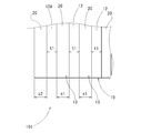
以下に、本発明の実施形態を説明する。本発明の一実施形態を示すヒートシンク101は、図1及び図2の観察画像と、図3~図5に示すように、金属成形体10と複数のコイル状金属線材21からなる充填体20とを組み合わせた複合構造とされている。
Hereinafter, embodiments of the present invention will be described. A heat sink 101 according to an embodiment of the present invention includes an observation image of FIGS. 1 and 2, and a filling body 20 composed of a metal molded body 10 and a plurality of coiled metal wires 21 as shown in FIGS. It is a composite structure that combines.
金属成形体21は、平板状の基板部11と、その基板部11の片面に立設されて相互に平行に配置された多数の帯板状(プレート状)のフィン部12と、これらフィン部12間に形成された溝部13内に充填された複数のコイル状金属線材21からなる充填体20とを有している。
The metal molded body 21 includes a plate-like substrate portion 11, a large number of strip-like (plate-like) fin portions 12 that are erected on one side of the substrate portion 11 and arranged in parallel to each other, and these fin portions 12 and a filling body 20 composed of a plurality of coiled metal wires 21 filled in a groove 13 formed between 12.
金属成形体10はアルミニウム成形体であり、基板部11とフィン部12とがアルミニウム(アルミニウム合金を含む。)の中実材によって一体に形成されている。充填体20は、図6及び図7に示すように、基板部11及びフィン部12(金属成形体10)と同じ材質のアルミニウムからなる複数のコイル状金属線材21により形成され、1個の溝部13内に充填された複数のコイル状金属線材21により構成されている。
The metal molded body 10 is an aluminum molded body, and the substrate portion 11 and the fin portion 12 are integrally formed of a solid material of aluminum (including an aluminum alloy). As shown in FIGS. 6 and 7, the filling body 20 is formed by a plurality of coiled metal wires 21 made of aluminum of the same material as the substrate portion 11 and the fin portion 12 (metal molding 10), and has one groove portion. 13 is composed of a plurality of coiled metal wires 21 filled in the inside.
金属成形体10及び充填体20は、熱伝導性が良好であれば、アルミニウム又はアルミニウム合金からなるものに限られるものではない。後述するように焼結により接合されるので、焼結できる金属であれば金属成形体10と充填体20とが異なる金属からなるものでもよい。あるいは、はんだ付けやろう付けにより金属成形体10と充填体20とを接合する場合も、熱伝導性が良好ではんだ付けやろう付けが可能な金属であればよい。
The metal compact 10 and the filler 20 are not limited to those made of aluminum or an aluminum alloy as long as the thermal conductivity is good. Since it is joined by sintering as will be described later, the metal molded body 10 and the filler 20 may be made of different metals as long as they can be sintered. Alternatively, when the metal molded body 10 and the filler 20 are joined by soldering or brazing, any metal that has good thermal conductivity and can be soldered or brazed may be used.
図3~図5に示すように、基板部11は例えば矩形状の平面形状を有しており、フィン部12は基板部11の表面から所定の高さh1、所定の厚さt1で立設されている。図3に示す例では、フィン部12は、基板部11の表面と平行な面方向において、縦方向(奥行方向、長さ方向)の全長にわたって設けられ、基板部11の横方向(幅方向)に所定の離間間隔c1をおいて相互に平行に並べられている。各フィン部12の間に離間間隔c1の開口幅を有する溝部13が設けられている。
As shown in FIGS. 3 to 5, the substrate portion 11 has, for example, a rectangular planar shape, and the fin portion 12 is erected from the surface of the substrate portion 11 with a predetermined height h1 and a predetermined thickness t1. Has been. In the example shown in FIG. 3, the fin portion 12 is provided over the entire length in the vertical direction (depth direction, length direction) in the plane direction parallel to the surface of the substrate portion 11, and the lateral direction (width direction) of the substrate portion 11. Are arranged in parallel with each other with a predetermined separation interval c1. Between each fin part 12, the groove part 13 which has the opening width of the space | interval c1 is provided.
このヒートシンク101においてこれらのフィン部12は、ヒートシンク101においては両側部の最も外側に配置される外側フィン部12Aの外側面が基板部11の両側縁面よりも内側に配置されているが、外側フィン部12Aの外側面と基板部11の両側縁面は同一面であっても良い。この場合、外側フィン部12Aの外側には充填体20は配置されない。すなわち、外側フィン部12Aは、基板部11の両側縁面よりも必ずしも内側に配置しなくても良い。
In the heat sink 101, these fin portions 12 are arranged such that the outer surface of the outer fin portion 12 </ b> A arranged on the outermost side of both sides of the heat sink 101 is arranged on the inner side of the both side edge surfaces of the substrate portion 11. The outer surface of the fin portion 12A and the side edge surfaces of the substrate portion 11 may be the same surface. In this case, the filler 20 is not disposed outside the outer fin portion 12A. In other words, the outer fin portion 12 </ b> A does not necessarily have to be arranged on the inner side of the side edge surfaces of the substrate portion 11.
外側フィン部12Aの外側面から基板部11の側縁面までの離間距離c2はフィン部12間の離間間隔c1と同じか、離間間隔c1より小さく形成されている。
The separation distance c2 from the outer surface of the outer fin portion 12A to the side edge surface of the substrate portion 11 is the same as or smaller than the separation interval c1 between the fin portions 12.
充填体20を構成しているコイル状金属線材21は、図7に模式的に示したように、全体としてはコイル状に巻回されているが、完全なコイル形状ではなく、全体にねじられるようにして形成されている。一端部(大径側端部21a)側の第1外径d1が他端部(小径側端部21b)側の第2外径d2より大きく形成されている。
As schematically shown in FIG. 7, the coil-shaped metal wire 21 constituting the filling body 20 is wound in a coil shape as a whole, but is not a complete coil shape but is twisted in its entirety. It is formed in this way. The first outer diameter d1 on the one end (large diameter side end 21a) side is formed larger than the second outer diameter d2 on the other end (small diameter side end 21b) side.
ここで、外径の大きい側の端部を大径側端部21a、小さい側の端部を小径側端部21bとする。コイル状金属線材21は略螺旋状にねじられて変形しているため、コイル状金属線材21の外径を円の外径として測定することは困難であるので、その先端からほぼ1巻き分以上の線材において最も外側に配置され、180°対向する2箇所をコイルの長さ方向と直交する方向に測定したときに得られる寸法を外径とする。
Here, the end portion on the larger outer diameter side is referred to as the large-diameter side end portion 21a, and the end portion on the smaller side is referred to as the small-diameter side end portion 21b. Since the coiled metal wire 21 is twisted and deformed in a substantially spiral shape, it is difficult to measure the outer diameter of the coiled metal wire 21 as the outer diameter of a circle. The outer diameter is defined as a dimension obtained when two places that are arranged on the outermost side and are opposed to each other by 180 ° are measured in a direction orthogonal to the length direction of the coil.
充填体20における各コイル状金属線材21は、単コイル全長(一つのコイル状金属線材の全長)をLmm、巻き数をNとしたとき、N/Lが0.1mm-1以上とされ、最大外径をDAmm、最小外径をDBmmとしたとき、(DA-DB)/Lが0.05以上を有する。ここでいうコイル状金属線材21の最大外径DAは、コイル状金属線材21を単体で測定した場合の第1外径d1ではなく、フィン部12間に充填されることにより径方向に押圧変形された状態のときの最大長径とその直角に対応する短径の平均値とする。
Each coil-shaped metal wire 21 in the packing 20 has a maximum length of a single coil (the total length of one coil-shaped metal wire) as Lmm and the number of turns as N, and N / L is 0.1 mm −1 or more. When the outer diameter is DAmm and the minimum outer diameter is DBmm, (DA-DB) / L is 0.05 or more. The maximum outer diameter DA of the coiled metal wire 21 here is not the first outer diameter d1 when the coiled metal wire 21 is measured alone, but is pressed and deformed in the radial direction by being filled between the fin portions 12. The average value of the major axis and the minor axis corresponding to the right angle of the maximum major axis in the state of being made.
各コイル状金属線材21の長さ方向に直交する横断面形状は、図9に示すように、円形ではなく、三角形状に形成されている。
The cross-sectional shape orthogonal to the length direction of each coiled metal wire 21 is not a circle but a triangle as shown in FIG.
充填体20は、フィン部12の離間間隔c1を埋めるように、フィン部12の長さ方向に沿って複数設けられ、各溝部13の内面(フィン部12又は基板部11の表面)に焼結部(冶金的接合部)22を介して接合されている。図6に示すように、充填体20における各コイル状金属線材21は、その全てが必ずしもフィン部12又は基板部11に接合されているとは限らず、コイル状金属線材21同士に対してのみ焼結部22を介して接合されている場合もある。ただし、溝部13内の1個の充填体20としては、全長のいずれかの部分でフィン部12又は基板部11に焼結部22を介して接合されている。
A plurality of fillers 20 are provided along the length direction of the fin portion 12 so as to fill the spacing c1 of the fin portion 12, and sintered on the inner surface of each groove portion 13 (the surface of the fin portion 12 or the substrate portion 11). It is joined via a portion (metallurgical joint) 22. As shown in FIG. 6, all of the coiled metal wires 21 in the filling body 20 are not necessarily joined to the fin portion 12 or the substrate portion 11, but only to the coiled metal wires 21. In some cases, they are joined via the sintered portion 22. However, the single filler 20 in the groove 13 is joined to the fin portion 12 or the substrate portion 11 via the sintered portion 22 at any part of the entire length.
言い換えれば、各コイル状金属線材21においては、金属成形体10の溝部13の内面と他のコイル状金属線材21の両方に焼結部22を介して接合されているものもあれば、金属成形体10の溝部13の内面には接合されずに、他のコイル状金属線材21に焼結部22を介して接合されたもの、あるいは、逆に、他のコイル状金属線材21には接合されずに、金属成形体10の溝部13の内面に焼結部22を介して接合されたものも混在している。図6において、ハッチングして示したコイル状金属線材21は、金属成形体10には接合されておらず、他のコイル状金属線材21のみに接合されている。
In other words, each coil-shaped metal wire 21 may be joined to both the inner surface of the groove 13 of the metal molded body 10 and the other coil-shaped metal wire 21 via the sintered portion 22. It is not joined to the inner surface of the groove 13 of the body 10 but joined to another coiled metal wire 21 via the sintered part 22, or conversely, joined to another coiled metal wire 21. Moreover, what was joined to the inner surface of the groove part 13 of the metal molded body 10 via the sintered part 22 is also mixed. In FIG. 6, the coiled metal wire 21 shown hatched is not joined to the metal molded body 10, and is joined only to the other coiled metal wire 21.
前述したように、各コイル状金属線材21は、大径側端部21aと小径側端部21bとで外径が異なる。各コイル状金属線材21は、コイルの長さ方向を金属成形体10の各フィン部12間の溝部13の長さ方向に沿うように配置されることにより、大径側端部21aから小径側端部21bに向かうコイル状金属線材21の円周方向(線材の側面)が溝部13の長さ方向と交差するので、溝部13内を流れる熱媒の流れを受けるようにコイル状金属線材21が交差して配置される。コイル状金属線材21の横断面が、複数の平面又は湾曲面を組み合わせた三角形状をなしていることから、熱媒の流れに対してその平面又は湾曲面が交差する。
As described above, the outer diameters of the coiled metal wires 21 are different between the large-diameter side end 21a and the small-diameter side end 21b. Each coil-shaped metal wire 21 is arranged so that the length direction of the coil is along the length direction of the groove portion 13 between each fin portion 12 of the metal molded body 10, so that the small diameter side from the large diameter side end portion 21 a. Since the circumferential direction (side surface of the wire) of the coiled metal wire 21 toward the end 21b intersects the length direction of the groove 13, the coiled metal wire 21 receives the flow of the heat medium flowing in the groove 13. It is arranged to intersect. Since the cross section of the coiled metal wire 21 has a triangular shape combining a plurality of flat surfaces or curved surfaces, the flat surfaces or curved surfaces intersect the flow of the heat medium.
充填体20を構成するコイル状金属線材21は、精密に加工して得られる形状のものだけでなく、フライス盤等による切削加工によって生じた切削片(図8及び図9参照)が好適に用いられる。切削片は、切削工具の切れ刃の形状、特に切れ刃における逃げ面の形状や、被削材の切削特性、切削条件等によって横断面形状を特定できるが、その形状は一定ではなく、不定形である。図8,9に示す切削片のように、コイル状金属線材21の横断面形状は複数の角部を有しており、その角部間の面は前述した平面、湾曲面の他、若干の凹凸のある曲面等によって構成される。
The coiled metal wire 21 constituting the filler 20 is preferably not only of a shape obtained by precision machining but also a cutting piece (see FIGS. 8 and 9) generated by cutting with a milling machine or the like. . The cross-sectional shape of the cutting piece can be specified by the shape of the cutting edge of the cutting tool, particularly the shape of the flank face of the cutting edge, the cutting characteristics of the work material, the cutting conditions, etc., but the shape is not constant and is indefinite It is. As shown in FIGS. 8 and 9, the cross-sectional shape of the coiled metal wire 21 has a plurality of corners, and the surface between the corners is slightly flat in addition to the plane and curved surfaces described above. Consists of a curved surface with irregularities.
本発明において、コイル状金属線材の横断面形状は三角形に限るものではなく、四角形、五角形のものも用いることができる。
In the present invention, the cross-sectional shape of the coiled metal wire is not limited to a triangle, and a rectangular or pentagonal shape can also be used.
このヒートシンク101において、熱媒が流通可能な空隙の大きさ(空隙率)が、熱媒の圧力損失や熱伝達量に影響する。空隙率は、基板部11の表面で熱媒が流通させられる領域の平面積(金属成形体10の平面積、図3ではS1×S2)とフィン部12の高さh1との積を全体体積Vとして、全体体積Vに対する空隙の体積(フィン部12及び充填体20の金属(アルミニウム)部分を除く空間の体積)の比率として求める。ヒートシンク101における空隙率は、50%以上65%以下とするのが好ましい。
In this heat sink 101, the size of the air gap through which the heat medium can flow (void ratio) affects the pressure loss and heat transfer amount of the heat medium. The porosity is the total volume of the product of the flat area of the region through which the heat medium is circulated on the surface of the substrate part 11 (the flat area of the metal molded body 10, S1 × S2 in FIG. 3) and the height h1 of the fin part 12. V is determined as the ratio of the void volume to the entire volume V (the volume of the space excluding the fin portion 12 and the metal (aluminum) portion of the filler 20). The porosity of the heat sink 101 is preferably 50% or more and 65% or less.
図3に示す例のように、フィン部12が立設されている金属成形体10の表面の全体が大気等に露出し、その表面全体で熱媒(例えば空気や水)と熱交換する。空隙率を計算するための全体体積Vは、金属成形体10の平面積(S1×S2)とフィン部12の高さh1との積とする。
As in the example shown in FIG. 3, the entire surface of the metal molded body 10 on which the fin portion 12 is erected is exposed to the atmosphere or the like, and heat exchange with a heat medium (for example, air or water) is performed on the entire surface. The total volume V for calculating the porosity is the product of the flat area (S1 × S2) of the metal molded body 10 and the height h1 of the fin portion 12.
このように構成したヒートシンク101を製造する場合、例えばアルミニウムの押出成形、鍛造成形、鋳造成形、あるいは基板部11とフィン部12とを接合するろう接などにより、基板部11とフィン部12とを一体に有する中実材の金属成形体10を形成する。金属成形体10に対して、各フィン部12間の溝部13内に、図10Aに示す型51を用いてコイル状金属線材21(充填体20)を接合する。
When manufacturing the heat sink 101 configured as described above, the substrate portion 11 and the fin portion 12 are bonded to each other by, for example, aluminum extrusion, forging, casting, or brazing that joins the substrate portion 11 and the fin portion 12. A solid metal molding 10 which is integrally formed is formed. A coil-shaped metal wire 21 (filler 20) is joined to the metal molded body 10 using a mold 51 shown in FIG.
コイル状金属線材21の接合には、マグネシウムとシリコンの混合粉末を用いる。MgおよびSiはAlの共晶元素であり、アルミニウム合金製の線材表面に付着させて加熱することにより、線材の付着部分だけを溶融させ、接合させることができる。混合粉末におけるマグネシウムとシリコンの好適な混合比率は、例えば重量比でマグネシウム1に対してシリコン1.5であり、これによりコイル状金属線材21の接合強度を十分に確保できる。この混合粉末は、高温で焼失する性質を有するバインダーを用いてコイル状金属線材21の表面に付着させる。
A mixed powder of magnesium and silicon is used for joining the coiled metal wire 21. Mg and Si are eutectic elements of Al, and by adhering to the surface of an aluminum alloy wire and heating, only the adhering portion of the wire can be melted and bonded. A suitable mixing ratio of magnesium and silicon in the mixed powder is, for example, 1.5 by weight with respect to magnesium 1 and silicon 1.5, whereby the bonding strength of the coiled metal wire 21 can be sufficiently ensured. This mixed powder is attached to the surface of the coiled metal wire 21 using a binder having the property of burning off at a high temperature.
型51は、金属成形体10及び充填体20のコイル状金属線材21と反応しにくい材料(例えばカーボン等)からなり、図10Aに示すように、フィン部12を収容するための矩形状の凹部52を片面に有する板状に形成されている。型51を図10Bに示すように基板部11(金属成形体10)に対向するように重ね合わせると、金属成形体10(基板部11および各フィン部12)と型51との間に充填体20を形成するための空間53が形成される。
The mold 51 is made of a material that does not easily react with the coil-shaped metal wire 21 of the metal molded body 10 and the filling body 20 (for example, carbon or the like), and as shown in FIG. It is formed in a plate shape having 52 on one side. When the mold 51 is overlaid so as to face the substrate portion 11 (metal molded body 10) as shown in FIG. 10B, a filler is placed between the metal molded body 10 (substrate portion 11 and each fin portion 12) and the mold 51. A space 53 for forming 20 is formed.
コイル状金属線材21は、フライス盤等の切削加工で生じた切削片を用意する。図10Aに示すように、複数個のコイル状金属線材21の長さ方向を金属成形体10の各フィン部12間の溝部13の長さ方向に沿うように、溝部13上に並べて配置する。
The coiled metal wire 21 is prepared with a cut piece produced by cutting such as a milling machine. As shown in FIG. 10A, the plurality of coiled metal wires 21 are arranged side by side on the groove portion 13 so that the length direction of the groove portions 13 between the fin portions 12 of the metal molded body 10 is along the length direction.
コイル状金属線材21の大径側端部21aは、フィン部12の離間間隔c1より大きい外径のものも、離間間隔1cと同程度のものも、離間間隔c1より小さい外径のものも存在する。小径側端部21bも離間間隔c1より大きいもの、同程度のもの、小さいものが存在する。そこでまず、コイル状金属線材21の大径側端部21aの第1外径d1が各フィン部12の離間間隔c1よりも大きいものを溝部13上部のフィン部12間に並べる。その後、大径側端部21aの第1外径d1が離間間隔c1よりも小さいものは、フィン部12間に配置したコイル状金属線材21に重ねるようにして配置する。このように配置すると、各コイル状金属線材21は図10Aに示すように溝部13内に落下せず、互いに接触した状態で各フィン部12の上端部に保持される。
The large-diameter side end portion 21a of the coiled metal wire 21 has an outer diameter larger than the separation interval c1 of the fin portion 12, the same size as the separation interval 1c, or an outer diameter smaller than the separation interval c1. To do. There are also small-diameter side end portions 21b that are larger, similar, or smaller than the separation interval c1. Accordingly, first, the first outer diameter d1 of the large-diameter side end portion 21a of the coiled metal wire 21 is arranged between the fin portions 12 above the groove portion 13 so as to be larger than the separation interval c1 of the fin portions 12. After that, the first outer diameter d1 of the large-diameter side end portion 21a is smaller than the separation interval c1 and is disposed so as to overlap the coiled metal wire 21 disposed between the fin portions 12. When arranged in this way, each coiled metal wire 21 does not fall into the groove 13 as shown in FIG. 10A but is held at the upper end of each fin 12 in contact with each other.
上述したマグネシウムとシリコンの混合粉末をバインダーにより表面に付着させたコイル状金属線材21をフィン部12の間の溝部13上に並べて配置した後、型51を金属成形体10に重ね合わせて前進させて、コイル状金属線材21を溝部13内に押し込み、各空間53内にコイル状金属線材21を充填する。
After arranging the coiled metal wire 21 in which the mixed powder of magnesium and silicon described above is adhered to the surface with a binder on the groove portion 13 between the fin portions 12, the die 51 is overlapped with the metal molded body 10 and advanced. Then, the coiled metal wire 21 is pushed into the groove 13 to fill the spaces 53 with the coiled metal wire 21.
そして、例えば不活性雰囲気で600℃~660℃の温度で0.5分~60分間、加熱することにより、コイル状金属線材21と金属成形体10(フィン部12又は基板部11)との各接点およびコイル状金属線材21相互間の接点に焼結部22を形成して焼結することにより、金属成形体10と充填体20及び充填体20内のコイル状金属線材21同士が焼結部22を介して一体に接合されたヒートシンク101を得ることができる。
Then, for example, by heating at a temperature of 600 ° C. to 660 ° C. for 0.5 minutes to 60 minutes in an inert atmosphere, each of the coiled metal wire 21 and the metal molded body 10 (fin portion 12 or substrate portion 11) is obtained. By forming and sintering the sintered portion 22 at the contact between the contact and the coiled metal wire 21, the metal molded body 10, the filler 20, and the coiled metal wire 21 in the filler 20 are sintered together. Thus, the heat sink 101 can be obtained that is integrally joined via the contact 22.
このように構成されるヒートシンク101においては、金属成形体10の各フィン部12間の各溝部13内に各充填体20が充填されており、各フィン部12及び基板部11(金属成形体10)と充填体20とを合わせた広い面積で熱移動が行われる。また、フィン部12及び基板部11と充填体20とは焼結部22を介して接合されているので、フィン部12及び基板部11と充填体20との接合界面の熱抵抗が小さく、基板部11及びフィン部12から充填体20への熱移動が円滑に促進される。そして、熱媒が充填体20内の空隙を通って流れることにより、充填体20、フィン部12及び基板部11の表面と熱媒との間で熱交換される。ヒートシンク101には充填体20により大きな表面積が形成されているので、金属成形体10から充填体20が受けた熱が熱媒に効率的に移動することにより、優れた熱伝達率が得られる。充填体20は熱媒の流れの障害となり、熱媒の流れを乱すことができるため、中実材のみからなるヒートシンクと比較して、比表面積が大きくなる以上に熱交換が促進される効果がある。
In the heat sink 101 configured in this manner, each filler body 20 is filled in each groove portion 13 between each fin portion 12 of the metal molded body 10, and each fin portion 12 and the substrate portion 11 (the metal molded body 10). ) And the filling body 20 are moved in a wide area. Moreover, since the fin part 12 and the board | substrate part 11 and the filler 20 are joined via the sintered part 22, the thermal resistance of the joining interface of the fin part 12 and the board | substrate part 11 and the filler 20 is small, and it is a board | substrate. The heat transfer from the part 11 and the fin part 12 to the filling body 20 is smoothly promoted. Then, when the heat medium flows through the gaps in the filling body 20, heat exchange is performed between the heat medium and the surfaces of the filling body 20, the fin part 12, and the substrate part 11. Since the heat sink 101 has a large surface area formed by the filler 20, the heat received by the filler 20 from the metal molded body 10 is efficiently transferred to the heat medium, so that an excellent heat transfer coefficient can be obtained. Since the filling body 20 becomes an obstacle to the flow of the heat medium and can disturb the flow of the heat medium, the heat exchange is promoted more than the specific surface area is increased as compared with the heat sink made of only the solid material. is there.
また、前述したように、コイル状金属線材21は空隙の開口径が大きいため、発泡金属や繊維多孔体と比べ、充填体20は圧力損失が低い。充填体20は、各コイル状金属線材21の太さや外径、充填方法を変えるだけで、空隙率の大きさ等を自在に制御できるため、製品設計の自由度が高い。
As described above, since the coiled metal wire 21 has a large opening diameter of the gap, the filler 20 has a lower pressure loss than the foam metal and the fiber porous body. Since the filling body 20 can freely control the size of the porosity and the like simply by changing the thickness, outer diameter, and filling method of each coiled metal wire 21, the degree of freedom in product design is high.
フィン部12及び基板部11と充填体20とは焼結部22において焼結によって接合され、ろう材を用いていないので、ろう材の浸透による充填体20の空隙率の低下(金属密度の増加)が生じない。ただし、空隙率を低下させすぎない適量のろう材やはんだ材であれば使用してもよく、その場合も空隙率が50%以上65%以下であると好ましい。本発明においては、焼結部やろう接部を含めて、フィン部12及び基板部11と充填体20との接合部を冶金的接合部と称す。
Since the fin part 12 and the board | substrate part 11 and the filler 20 are joined by sintering in the sintering part 22, and the brazing material is not used, the porosity of the filler 20 is reduced by the penetration of the brazing material (increase in the metal density). ) Does not occur. However, an appropriate amount of brazing material or solder material that does not excessively reduce the porosity may be used. In this case, the porosity is preferably 50% or more and 65% or less. In the present invention, the joint part between the fin part 12 and the substrate part 11 and the filler 20 including the sintered part and the brazed part is referred to as a metallurgical joint part.
各コイル状金属線材21は、コイルの外径が一端部(大径側端部21a)側と他端部(小径側端部21b)側とで異なっているため、溝部13の長さ方向に沿う熱媒の流れに対して、その線材の各部が流れに対して交差するように配置され、熱媒からの熱を確実に受けることができる。また、各コイル状金属線材21の横断面形状が複数の平面又は曲率半径の大きい湾曲面により三角形状に形成されているため、その平面又は湾曲面が熱媒の流れに対して交差する方向で存在する。そして、これらの相乗作用により、熱媒の流れをコイル状金属線材21の平面又は湾曲面により受けて、熱媒からの熱を確実に受けるとともに、コイル状金属線材21の表面に流れが衝突して、コイル状金属線材21の後方で渦が発生し、その結果、熱媒の流れがより乱されてかく乱効果が高められ、熱交換をさらに促進することができる。
Each coil-shaped metal wire 21 has an outer diameter of the coil that is different between the one end (large diameter side end 21a) side and the other end (small diameter side end 21b) side. It arrange | positions so that each part of the wire may cross | intersect with respect to the flow with respect to the flow of the heat medium which follows, and can receive the heat from a heat medium reliably. Moreover, since the cross-sectional shape of each coil-shaped metal wire 21 is formed in a triangular shape by a plurality of planes or curved surfaces having a large curvature radius, the planes or curved surfaces intersect with the flow of the heat medium. Exists. And by these synergistic actions, the flow of the heat medium is received by the flat surface or the curved surface of the coiled metal wire 21 and the heat from the heat medium is reliably received, and the flow collides with the surface of the coiled metal wire 21. As a result, a vortex is generated behind the coiled metal wire 21, and as a result, the flow of the heat medium is more disturbed, the disturbance effect is enhanced, and heat exchange can be further promoted.
したがって、熱伝達率が高いヒートシンク101が実現できる。
Therefore, the heat sink 101 having a high heat transfer rate can be realized.
なお、本発明は上記実施形態に限定されるものではく、本発明の趣旨を逸脱しない範囲において種々の変更を加えることが可能である。
Note that the present invention is not limited to the above embodiment, and various modifications can be made without departing from the spirit of the present invention.
本発明の実施例(試料番号1~3)として、図3に示す上記実施形態の帯板状(プレート状)のフィン部12を有するヒートシンク101を作製した。基板部11は、縦寸法:S1=55mm、横寸法:S2=38mm、板厚:h0=4mmとし、フィン部12を基板部11の全長にわたって形成した。
As an example of the present invention (sample numbers 1 to 3), a heat sink 101 having a strip-like (plate-like) fin portion 12 of the above-described embodiment shown in FIG. 3 was produced. The substrate part 11 had a longitudinal dimension: S1 = 55 mm, a lateral dimension: S2 = 38 mm, a plate thickness: h0 = 4 mm, and the fin part 12 was formed over the entire length of the substrate part 11.
各フィン部12の高さh1は6mmとした。フィン部12の数、フィン部12の離間間隔(溝部13の幅)c1、基板部11の横方向の最も外側にある外側フィン部12Aの外側面から基板部11の側縁面まで(端溝部13A)の離間距離c2、コイル状金属線材21の最大外径DA、最小外径DB、コイル状金属線材21単体の全長(単コイル全長)L、巻き数Nは表1の通りとした。
The height h1 of each fin part 12 was 6 mm. The number of fin portions 12, the spacing between the fin portions 12 (the width of the groove portion 13) c <b> 1, from the outer surface of the outer fin portion 12 </ b> A that is the outermost side in the lateral direction of the substrate portion 11 to The separation distance c2 of 13A), the maximum outer diameter DA, the minimum outer diameter DB of the coiled metal wire 21, the total length (single coil total length) L of the coiled metal wire 21 alone, and the number of turns N are as shown in Table 1.
各コイル状金属線材21の最小外径DBは、前述の小径側端部21bの第2外径d2であるが、最大外径DAは、フィン部12の間に充填した状態での最大長径とその直角に対応する短径の平均値である。各実施例のコイル状金属線材21の断面はほぼ三角形状に形成されている。
The minimum outer diameter DB of each coiled metal wire 21 is the second outer diameter d2 of the small-diameter end 21b described above, but the maximum outer diameter DA is the maximum long diameter in a state of being filled between the fin portions 12. The average value of the minor axis corresponding to the right angle. The cross section of the coiled metal wire 21 of each embodiment is formed in a substantially triangular shape.
比較例(試料番号4,5)として、充填体として繊維多孔体を使用したヒートシンクを作製した。比較例の各ヒートシンクも、試料番号1~3の金属成形体10と同様の寸法で形成した。
As a comparative example (sample numbers 4 and 5), a heat sink using a porous fiber as a filler was produced. Each heat sink of the comparative example was also formed with the same dimensions as the metal molded body 10 of sample numbers 1 to 3.
金属成形体10及び充填体20の材料としては、A1050を用いた。
A1050 was used as the material of the metal compact 10 and the filler 20.
空隙率は、フィン部12が立設されている基板部11の表面全体(全体体積V=S1×S2×h1)で熱媒と熱交換するものとして、充填体20の体積(充填材の重量/充填材の密度)をもとに算出した。
The porosity is defined as the volume of the filler 20 (weight of the filler) assuming that heat exchange with the heat medium is performed on the entire surface of the substrate portion 11 on which the fin portions 12 are erected (overall volume V = S1 × S2 × h1). / Density of the filler).
圧力損失の測定には、一方向に熱媒(水)が流れる冷却性能測定装置を使用した。測定装置に各ヒートシンクをはめ込み、各フィン部12間に30℃の熱媒を体積流量4L/min(一定)で流し、ヒートシンク前後の差圧を測定して、これを圧力損失とした。熱媒は、フィン部12の長さ方向に流通させた。
Measured pressure loss was a cooling performance measuring device in which a heat medium (water) flows in one direction. Each heat sink was fitted into the measuring device, a heating medium of 30 ° C. was flowed between the fin portions 12 at a volume flow rate of 4 L / min (constant), the differential pressure before and after the heat sink was measured, and this was taken as the pressure loss. The heat medium was circulated in the length direction of the fin portion 12.
熱伝達率の導出には、圧力損失測定で用いた冷却性能測定装置による試験で得られた各種測定値を使用した。ヒートシンク101の基板部11の裏面(フィン部12が設けられていない面)上に柔軟性のある放熱グリス、被冷却体(発熱素子)、断熱材の順で重ね、押さえ治具により被冷却体を50cm・Nのトルクで圧着した。25℃の一定の温度に調整された環境で、各フィン部12間(各溝部13内)に30℃の熱媒(水)を4L/min(一定)で5分間流し、被冷却体の温度(発熱前温度)が安定していることを確認した後、約450Wの電力Qで被冷却体を15分間発熱させ、基板部11中央の被冷却体と基板部11との界面の温度Tb1および熱媒の水温Twを測定した。
For the derivation of the heat transfer coefficient, various measured values obtained by the test using the cooling performance measuring apparatus used in the pressure loss measurement were used. On the back surface of the substrate portion 11 of the heat sink 101 (the surface on which the fin portion 12 is not provided), a flexible heat dissipating grease, a cooled object (heating element), and a heat insulating material are stacked in this order, and the cooled object is pressed by a holding jig. Was pressure-bonded with a torque of 50 cm · N. In an environment adjusted to a constant temperature of 25 ° C., a 30 ° C. heating medium (water) is allowed to flow at a rate of 4 L / min (constant) for 5 minutes between the fin portions 12 (in each groove portion 13). After confirming that (temperature before heat generation) is stable, the object to be cooled is heated for 15 minutes with a power Q of about 450 W, and the temperature Tb1 of the interface between the object to be cooled at the center of the substrate part 11 and the substrate part 11 and The water temperature Tw of the heat medium was measured.
熱媒(水)と基板部11との界面の温度Tb2を、温度Tb1を用いてTb2=[Tb1-{Q×h0/(A×k)}]の計算式から算出した。ここで、h0は基板部11の厚み、Aは被冷却体の基板部11への取付面積、kはA1050の熱伝導率である。ヒートシンクの熱伝達率Hは、H=[Q/{A×(Tb2-Tw)}]の計算式から算出し、ヒートシンクの熱伝達率指標として評価した。すなわち、熱伝達率Hが大きいほど熱交換性能に優れたヒートシンクである。
The temperature Tb2 at the interface between the heat medium (water) and the substrate portion 11 was calculated from the calculation formula Tb2 = [Tb1− {Q × h0 / (A × k)}] using the temperature Tb1. Here, h0 is the thickness of the substrate part 11, A is the mounting area of the body to be cooled to the substrate part 11, and k is the thermal conductivity of A1050. The heat transfer coefficient H of the heat sink was calculated from the calculation formula of H = [Q / {A × (Tb2-Tw)}] and evaluated as a heat transfer coefficient index of the heat sink. That is, the heat sink has a higher heat exchange performance as the heat transfer coefficient H is larger.
これらの結果を表1~表2に示す。試料番号4及び5は、充填体を設けず、金属成形体10のみからなる比較例のヒートシンクであるから、表1~表2中、充填体に関係する項目は「―」で記載した。
These results are shown in Tables 1 and 2. Since Sample Nos. 4 and 5 are heat sinks of comparative examples which are not provided with a filler and are composed only of the metal molded body 10, items related to the filler in Tables 1 and 2 are indicated by “-”.


これらの結果からわかるように、充填体20を有する試料番号1~3では、熱伝達率が40kw/m2K以上であり、圧力損失も小さい。これに対して試料番号4,5は、熱伝達率は高いが、圧力損失が大きくなっている。
As can be seen from these results, Sample Nos. 1 to 3 having the filler 20 have a heat transfer coefficient of 40 kw / m 2 K or more and a small pressure loss. In contrast, Sample Nos. 4 and 5 have a high heat transfer coefficient, but a large pressure loss.
ヒートシンクの熱伝達率をさらに向上させ、圧力損失をさらに低下させることができる。
The heat transfer coefficient of the heat sink can be further improved and the pressure loss can be further reduced.
101 ヒートシンク
10 金属成形体
11 基板部
12 フィン部
12A 外側フィン部
13 溝部
13A 端溝部
20 充填体
21 コイル状金属線材
21a 大径側端部
21b 小径側端部
22 焼結部(冶金的接合部)
51 型
c1 離間間隔
c2 離間距離
DA 最大外径
DB 最少外径
d1 第1外径
d2 第2外径
h0 厚み
h1 高さ
t1 厚さ
L 単コイル全長
N 巻き数
V 全体体積
DESCRIPTION OFSYMBOLS 101 Heat sink 10 Metal molded object 11 Substrate part 12 Fin part 12A Outer fin part 13 Groove part 13A End groove part 20 Filling body 21 Coiled metal wire 21a Large diameter side edge part 21b Small diameter side edge part 22 Sintered part (metallurgical joining part)
51 type c1 separation distance c2 separation distance DA maximum outer diameter DB minimum outer diameter d1 first outer diameter d2 second outer diameter h0 thickness h1 height t1 thickness L single coil total length N number of turns V overall volume
10 金属成形体
11 基板部
12 フィン部
12A 外側フィン部
13 溝部
13A 端溝部
20 充填体
21 コイル状金属線材
21a 大径側端部
21b 小径側端部
22 焼結部(冶金的接合部)
51 型
c1 離間間隔
c2 離間距離
DA 最大外径
DB 最少外径
d1 第1外径
d2 第2外径
h0 厚み
h1 高さ
t1 厚さ
L 単コイル全長
N 巻き数
V 全体体積
DESCRIPTION OF
51 type c1 separation distance c2 separation distance DA maximum outer diameter DB minimum outer diameter d1 first outer diameter d2 second outer diameter h0 thickness h1 height t1 thickness L single coil total length N number of turns V overall volume
Claims (6)
- 基板部、及び前記基板部の表面に立設されて相互に平行に配置された2以上のフィン部を有する金属成形体と、
前記金属成形体の前記フィン部間に形成された1以上の溝部内に充填された複数のコイル状金属線材からなる1以上の充填体と
を有し、
前記コイル状金属線材の外径は、一端部側の第1外径と他端部側の第2外径とで異なっており、
前記コイル状金属線材はそれぞれ一部が前記金属成形体の前記溝部内面および他の前記コイル状金属線材の少なくともいずれかに冶金的接合されている
ことを特徴とするヒートシンク。 A metal molded body having a substrate portion and two or more fin portions that are erected on the surface of the substrate portion and arranged in parallel to each other;
Having one or more fillers composed of a plurality of coiled metal wires filled in one or more grooves formed between the fin portions of the metal molded body,
The outer diameter of the coiled metal wire is different between the first outer diameter on one end side and the second outer diameter on the other end side,
A part of each of the coiled metal wires is metallurgically joined to at least one of the inner surface of the groove of the metal molded body and the other coiled metal wires. - 前記コイル状金属線材の長さ方向と直交する方向の横断面形状は五角形以下の多角形に形成されていることを特徴とする請求項1に記載のヒートシンク。 The heat sink according to claim 1, wherein a cross-sectional shape in a direction orthogonal to a length direction of the coiled metal wire is formed in a polygon of a pentagon or less.
- 前記コイル状金属線材は、単コイル全長をLmm、巻き数をNとしたとき、N/Lが0.1mm-1以上であることを特徴とする請求項1又は2に記載のヒートシンク。 The heat sink according to claim 1 or 2, wherein the coiled metal wire has N / L of 0.1 mm -1 or more, where Lmm is the total length of a single coil and N is the number of turns.
- 前記コイル状金属線材の最大外径をDAmm、最小外径をDBmm、単コイル全長をLmmとしたとき、(DA-DB)/Lが0.05以上であることを特徴とする1から3のいずれか一項に記載のヒートシンク。 1 to 3, wherein (DA-DB) / L is 0.05 or more when the maximum outer diameter of the coiled metal wire is DAmm, the minimum outer diameter is DBmm, and the total length of the single coil is Lmm. The heat sink as described in any one of Claims.
- 前記コイル状金属線材は、切削加工により生じる切削片であることを特徴とする請求項1から4のいずれか一項に記載のヒートシンク。 The heat sink according to any one of claims 1 to 4, wherein the coiled metal wire is a cut piece generated by cutting.
- 前記金属成形体の平面積をS1×S2、前記フィン部の高さをh1として設定した全体体積V=S1×S2×h1に対して、空間の体積が占める空隙率が50%以上65%以下であることを特徴とする請求項1から5のいずれかに記載のヒートシンク。 The void ratio occupied by the volume of space is 50% or more and 65% or less with respect to the total volume V = S1 × S2 × h1 where the flat area of the metal molded body is set to S1 × S2 and the height of the fin portion is set to h1. The heat sink according to any one of claims 1 to 5, wherein:
Priority Applications (3)
| Application Number | Priority Date | Filing Date | Title |
|---|---|---|---|
| US16/971,531 US11373923B2 (en) | 2018-02-21 | 2019-01-09 | Heat sink with coiled metal-wire material |
| CN201980011168.3A CN111670494B (en) | 2018-02-21 | 2019-01-09 | Radiator |
| EP19757119.3A EP3758056A4 (en) | 2018-02-21 | 2019-01-09 | Heat sink |
Applications Claiming Priority (2)
| Application Number | Priority Date | Filing Date | Title |
|---|---|---|---|
| JP2018-028359 | 2018-02-21 | ||
| JP2018028359A JP7098954B2 (en) | 2018-02-21 | 2018-02-21 | heatsink |
Publications (1)
| Publication Number | Publication Date |
|---|---|
| WO2019163313A1 true WO2019163313A1 (en) | 2019-08-29 |
Family
ID=67687678
Family Applications (1)
| Application Number | Title | Priority Date | Filing Date |
|---|---|---|---|
| PCT/JP2019/000291 WO2019163313A1 (en) | 2018-02-21 | 2019-01-09 | Heat sink |
Country Status (5)
| Country | Link |
|---|---|
| US (1) | US11373923B2 (en) |
| EP (1) | EP3758056A4 (en) |
| JP (1) | JP7098954B2 (en) |
| CN (1) | CN111670494B (en) |
| WO (1) | WO2019163313A1 (en) |
Cited By (1)
| Publication number | Priority date | Publication date | Assignee | Title |
|---|---|---|---|---|
| CN112802808A (en) * | 2019-11-14 | 2021-05-14 | 承奕科技股份有限公司 | Composite heat sink with plug-in port for heating element and heat sink with the same |
Families Citing this family (1)
| Publication number | Priority date | Publication date | Assignee | Title |
|---|---|---|---|---|
| JP7010105B2 (en) * | 2018-03-23 | 2022-01-26 | 三菱マテリアル株式会社 | Porous metal |
Citations (10)
| Publication number | Priority date | Publication date | Assignee | Title |
|---|---|---|---|---|
| JPH06275746A (en) | 1993-03-18 | 1994-09-30 | Hitachi Ltd | Semiconductor device |
| JPH0936284A (en) * | 1995-07-24 | 1997-02-07 | Atsushi Terada | Heat sink and heat exchanger |
| JP2003119536A (en) | 2001-10-10 | 2003-04-23 | Nippon Light Metal Co Ltd | Aluminum alloy for casting superior in thermal conductivity |
| WO2005067036A1 (en) * | 2004-01-07 | 2005-07-21 | Jisouken Co., Ltd. | Heat sink |
| JP2010531536A (en) * | 2007-07-05 | 2010-09-24 | ファウ テクノロジー カンパニー,リミテッド | Heat dissipation device including linear heat dissipation member and fanless LED lighting apparatus including the same |
| JP2012009482A (en) | 2010-06-22 | 2012-01-12 | Nitto Kogyo Co Ltd | Cooling fin |
| JP2014090209A (en) * | 2014-01-17 | 2014-05-15 | Panasonic Corp | Heat sink and air conditioner |
| JP2017149843A (en) | 2016-02-24 | 2017-08-31 | 東レ株式会社 | Polyester resin composition for transparent optical film |
| JP2018028359A (en) | 2016-08-18 | 2018-02-22 | マツダ株式会社 | Shift control device for automatic transmission |
| JP2018141614A (en) * | 2017-02-28 | 2018-09-13 | 三菱マテリアル株式会社 | Heat exchange member |
Family Cites Families (17)
| Publication number | Priority date | Publication date | Assignee | Title |
|---|---|---|---|---|
| US3262190A (en) * | 1961-07-10 | 1966-07-26 | Iit Res Inst | Method for the production of metallic heat transfer bodies |
| DE1751779A1 (en) * | 1968-07-29 | 1971-05-06 | Linde Ag | Device for evaporating liquids at low temperatures |
| US5497824A (en) * | 1990-01-18 | 1996-03-12 | Rouf; Mohammad A. | Method of improved heat transfer |
| US6761211B2 (en) * | 2000-03-14 | 2004-07-13 | Delphi Technologies, Inc. | High-performance heat sink for electronics cooling |
| US20020108743A1 (en) * | 2000-12-11 | 2002-08-15 | Wirtz Richard A. | Porous media heat sink apparatus |
| US6561267B2 (en) * | 2001-09-28 | 2003-05-13 | Intel Corporation | Heat sink and electronic circuit module including the same |
| US6591897B1 (en) * | 2002-02-20 | 2003-07-15 | Delphi Technologies, Inc. | High performance pin fin heat sink for electronics cooling |
| US6958912B2 (en) * | 2003-11-18 | 2005-10-25 | Intel Corporation | Enhanced heat exchanger |
| JP2008098591A (en) * | 2006-10-16 | 2008-04-24 | Jigyo Sozo Kenkyusho:Kk | Heat sink and method of manufacturing the same |
| US9704793B2 (en) * | 2011-01-04 | 2017-07-11 | Napra Co., Ltd. | Substrate for electronic device and electronic device |
| WO2013144829A1 (en) * | 2012-03-30 | 2013-10-03 | The Technology Innovation Agency | Cell stack heat sink panel with integral heat dissipating fin |
| JP5633658B2 (en) * | 2013-03-01 | 2014-12-03 | 三菱マテリアル株式会社 | Porous aluminum sintered body |
| JP2015220429A (en) * | 2014-05-21 | 2015-12-07 | ローム株式会社 | Semiconductor device |
| CN204835826U (en) * | 2015-06-10 | 2015-12-02 | 辽宁皓唯环境工程有限公司 | Permanent magnetism actuator conductor dish subassembly |
| BE1023686B1 (en) * | 2015-11-12 | 2017-06-15 | Maes Jonker Nv | DEVICE WITH METAL FOAM FOR ACCELERATED HEAT TRANSFER |
| CN205828369U (en) * | 2016-05-16 | 2016-12-21 | 吴嘉昇 | Heat spreader structures |
| CN205755233U (en) * | 2016-06-13 | 2016-11-30 | 西安交通大学 | A kind of metal foam radiator for electronic heating equipment natural cooling |
-
2018
- 2018-02-21 JP JP2018028359A patent/JP7098954B2/en active Active
-
2019
- 2019-01-09 WO PCT/JP2019/000291 patent/WO2019163313A1/en unknown
- 2019-01-09 EP EP19757119.3A patent/EP3758056A4/en active Pending
- 2019-01-09 US US16/971,531 patent/US11373923B2/en active Active
- 2019-01-09 CN CN201980011168.3A patent/CN111670494B/en active Active
Patent Citations (10)
| Publication number | Priority date | Publication date | Assignee | Title |
|---|---|---|---|---|
| JPH06275746A (en) | 1993-03-18 | 1994-09-30 | Hitachi Ltd | Semiconductor device |
| JPH0936284A (en) * | 1995-07-24 | 1997-02-07 | Atsushi Terada | Heat sink and heat exchanger |
| JP2003119536A (en) | 2001-10-10 | 2003-04-23 | Nippon Light Metal Co Ltd | Aluminum alloy for casting superior in thermal conductivity |
| WO2005067036A1 (en) * | 2004-01-07 | 2005-07-21 | Jisouken Co., Ltd. | Heat sink |
| JP2010531536A (en) * | 2007-07-05 | 2010-09-24 | ファウ テクノロジー カンパニー,リミテッド | Heat dissipation device including linear heat dissipation member and fanless LED lighting apparatus including the same |
| JP2012009482A (en) | 2010-06-22 | 2012-01-12 | Nitto Kogyo Co Ltd | Cooling fin |
| JP2014090209A (en) * | 2014-01-17 | 2014-05-15 | Panasonic Corp | Heat sink and air conditioner |
| JP2017149843A (en) | 2016-02-24 | 2017-08-31 | 東レ株式会社 | Polyester resin composition for transparent optical film |
| JP2018028359A (en) | 2016-08-18 | 2018-02-22 | マツダ株式会社 | Shift control device for automatic transmission |
| JP2018141614A (en) * | 2017-02-28 | 2018-09-13 | 三菱マテリアル株式会社 | Heat exchange member |
Non-Patent Citations (1)
| Title |
|---|
| See also references of EP3758056A4 |
Cited By (1)
| Publication number | Priority date | Publication date | Assignee | Title |
|---|---|---|---|---|
| CN112802808A (en) * | 2019-11-14 | 2021-05-14 | 承奕科技股份有限公司 | Composite heat sink with plug-in port for heating element and heat sink with the same |
Also Published As
| Publication number | Publication date |
|---|---|
| EP3758056A1 (en) | 2020-12-30 |
| JP2019145664A (en) | 2019-08-29 |
| EP3758056A4 (en) | 2021-12-01 |
| CN111670494A (en) | 2020-09-15 |
| US11373923B2 (en) | 2022-06-28 |
| US20210090971A1 (en) | 2021-03-25 |
| CN111670494B (en) | 2024-04-05 |
| JP7098954B2 (en) | 2022-07-12 |
Similar Documents
| Publication | Publication Date | Title |
|---|---|---|
| JP2007335663A (en) | Semiconductor module | |
| WO2019163313A1 (en) | Heat sink | |
| JP6547641B2 (en) | heatsink | |
| CN110998833A (en) | Heat radiator | |
| JP2005077052A (en) | Flat heat pipe | |
| JP2002026201A (en) | Radiator | |
| JP6863512B2 (en) | heatsink | |
| TW201835519A (en) | Heat exchange member | |
| JP6422726B2 (en) | Heat sink with circuit board and manufacturing method thereof | |
| JP5503682B2 (en) | Heat sink and method of manufacturing heat sink | |
| JP2003179189A (en) | Thin heat sink and its packaging structure | |
| JP2003060135A (en) | Radiation fin | |
| JP2003234443A (en) | Heat sink with fin | |
| EP1345266A1 (en) | Heat sink with extended surface area | |
| WO2022030197A1 (en) | Compoiste material, heat spreader and semiconductor package | |
| WO2023204167A1 (en) | Ceramic circuit board, semiconductor device, and semiconductor device production method | |
| JP6116404B2 (en) | Heat dissipation device | |
| JP6157287B2 (en) | Wiring member and printed circuit board | |
| JP6324008B2 (en) | Manufacturing method of heat dissipation device | |
| JP2008226899A (en) | Heat dissipation component and heat dissipation structure | |
| WO2018159605A1 (en) | Heat-exchange member | |
| JP6105437B2 (en) | Heat dissipation device | |
| JP2022177993A (en) | Heat sink and semiconductor package | |
| CN116558338A (en) | Heat pipe radiator and preparation method thereof | |
| JP5773703B2 (en) | Heat dissipation device |
Legal Events
| Date | Code | Title | Description |
|---|---|---|---|
| 121 | Ep: the epo has been informed by wipo that ep was designated in this application |
Ref document number: 19757119 Country of ref document: EP Kind code of ref document: A1 |
|
| NENP | Non-entry into the national phase |
Ref country code: DE |
|
| ENP | Entry into the national phase |
Ref document number: 2019757119 Country of ref document: EP Effective date: 20200921 |