WO2019156141A1 - Three-dimensional data encoding method, three-dimensional data decoding method, three-dimensional data encoding device, and three-dimensional data decoding device - Google Patents
Three-dimensional data encoding method, three-dimensional data decoding method, three-dimensional data encoding device, and three-dimensional data decoding device Download PDFInfo
- Publication number
- WO2019156141A1 WO2019156141A1 PCT/JP2019/004346 JP2019004346W WO2019156141A1 WO 2019156141 A1 WO2019156141 A1 WO 2019156141A1 JP 2019004346 W JP2019004346 W JP 2019004346W WO 2019156141 A1 WO2019156141 A1 WO 2019156141A1
- Authority
- WO
- WIPO (PCT)
- Prior art keywords
- information
- encoding
- node
- dimensional
- dimensional data
- Prior art date
Links
Images


Classifications
-
- H—ELECTRICITY
- H04—ELECTRIC COMMUNICATION TECHNIQUE
- H04N—PICTORIAL COMMUNICATION, e.g. TELEVISION
- H04N19/00—Methods or arrangements for coding, decoding, compressing or decompressing digital video signals
- H04N19/90—Methods or arrangements for coding, decoding, compressing or decompressing digital video signals using coding techniques not provided for in groups H04N19/10-H04N19/85, e.g. fractals
- H04N19/96—Tree coding, e.g. quad-tree coding
-
- G—PHYSICS
- G06—COMPUTING; CALCULATING OR COUNTING
- G06T—IMAGE DATA PROCESSING OR GENERATION, IN GENERAL
- G06T9/00—Image coding
- G06T9/001—Model-based coding, e.g. wire frame
-
- G—PHYSICS
- G06—COMPUTING; CALCULATING OR COUNTING
- G06T—IMAGE DATA PROCESSING OR GENERATION, IN GENERAL
- G06T9/00—Image coding
- G06T9/40—Tree coding, e.g. quadtree, octree
-
- H—ELECTRICITY
- H04—ELECTRIC COMMUNICATION TECHNIQUE
- H04N—PICTORIAL COMMUNICATION, e.g. TELEVISION
- H04N19/00—Methods or arrangements for coding, decoding, compressing or decompressing digital video signals
- H04N19/10—Methods or arrangements for coding, decoding, compressing or decompressing digital video signals using adaptive coding
- H04N19/102—Methods or arrangements for coding, decoding, compressing or decompressing digital video signals using adaptive coding characterised by the element, parameter or selection affected or controlled by the adaptive coding
- H04N19/103—Selection of coding mode or of prediction mode
- H04N19/107—Selection of coding mode or of prediction mode between spatial and temporal predictive coding, e.g. picture refresh
-
- H—ELECTRICITY
- H04—ELECTRIC COMMUNICATION TECHNIQUE
- H04N—PICTORIAL COMMUNICATION, e.g. TELEVISION
- H04N19/00—Methods or arrangements for coding, decoding, compressing or decompressing digital video signals
- H04N19/10—Methods or arrangements for coding, decoding, compressing or decompressing digital video signals using adaptive coding
- H04N19/134—Methods or arrangements for coding, decoding, compressing or decompressing digital video signals using adaptive coding characterised by the element, parameter or criterion affecting or controlling the adaptive coding
- H04N19/146—Data rate or code amount at the encoder output
- H04N19/149—Data rate or code amount at the encoder output by estimating the code amount by means of a model, e.g. mathematical model or statistical model
-
- H—ELECTRICITY
- H04—ELECTRIC COMMUNICATION TECHNIQUE
- H04N—PICTORIAL COMMUNICATION, e.g. TELEVISION
- H04N19/00—Methods or arrangements for coding, decoding, compressing or decompressing digital video signals
- H04N19/10—Methods or arrangements for coding, decoding, compressing or decompressing digital video signals using adaptive coding
- H04N19/134—Methods or arrangements for coding, decoding, compressing or decompressing digital video signals using adaptive coding characterised by the element, parameter or criterion affecting or controlling the adaptive coding
- H04N19/146—Data rate or code amount at the encoder output
- H04N19/152—Data rate or code amount at the encoder output by measuring the fullness of the transmission buffer
-
- H—ELECTRICITY
- H04—ELECTRIC COMMUNICATION TECHNIQUE
- H04N—PICTORIAL COMMUNICATION, e.g. TELEVISION
- H04N19/00—Methods or arrangements for coding, decoding, compressing or decompressing digital video signals
- H04N19/90—Methods or arrangements for coding, decoding, compressing or decompressing digital video signals using coding techniques not provided for in groups H04N19/10-H04N19/85, e.g. fractals
- H04N19/91—Entropy coding, e.g. variable length coding [VLC] or arithmetic coding
Definitions
- the present disclosure relates to a three-dimensional data encoding method, a three-dimensional data decoding method, a three-dimensional data encoding device, and a three-dimensional data decoding device.
- the three-dimensional data is acquired by various methods such as a distance sensor such as a range finder, a stereo camera, or a combination of a plurality of monocular cameras.
- a point cloud that represents the shape of a three-dimensional structure by a point group in a three-dimensional space.
- the position and color of the point cloud are stored.
- Point clouds are expected to become the mainstream representation method of 3D data, but point clouds have a very large amount of data. Therefore, in the storage or transmission of three-dimensional data, it is essential to compress the amount of data by encoding as in the case of two-dimensional moving images (for example, MPEG-4 AVC or HEVC standardized by MPEG). Become.
- point cloud compression is partially supported by a public library (Point Cloud Library) that performs point cloud related processing.
- a public library Point Cloud Library
- Patent Document 1 a technique for searching for and displaying facilities located around the vehicle using three-dimensional map data is known (for example, see Patent Document 1).
- a 3D data encoding method encodes information on a target node included in a N (N is an integer of 2 or more) binary tree structure of a plurality of 3D points included in 3D data,
- N is an integer of 2 or more
- Reference to information on the second node is prohibited.
- a 3D data decoding method decodes information on a target node included in a N (N is an integer of 2 or more) branch tree structure of a plurality of 3D points included in 3D data,
- N is an integer of 2 or more
- the reference of the information of the first node having the same parent node as the target node among the plurality of adjacent nodes spatially adjacent to the target node is permitted, and the second is different from the target node and the parent node. Prohibits reference to node information.
- the present disclosure can provide a three-dimensional data encoding method, a three-dimensional data decoding method, a three-dimensional data encoding device, or a three-dimensional data decoding device that can improve the encoding efficiency and reduce the processing amount.
- FIG. 1 is a diagram showing a configuration of encoded three-dimensional data according to the first embodiment.
- FIG. 2 is a diagram illustrating an example of a prediction structure between SPCs belonging to the lowest layer of the GOS according to the first embodiment.
- FIG. 3 is a diagram illustrating an example of a prediction structure between layers according to the first embodiment.
- FIG. 4 is a diagram illustrating an example of the coding order of GOS according to the first embodiment.
- FIG. 5 is a diagram illustrating an example of the coding order of GOS according to the first embodiment.
- FIG. 6 is a block diagram of the three-dimensional data encoding apparatus according to the first embodiment.
- FIG. 7 is a flowchart of the encoding process according to the first embodiment.
- FIG. 8 is a block diagram of the three-dimensional data decoding apparatus according to the first embodiment.
- FIG. 9 is a flowchart of the decoding process according to the first embodiment.
- FIG. 10 is a diagram illustrating an example of meta information according to the first embodiment.
- FIG. 11 is a diagram illustrating a configuration example of the SWLD according to the second embodiment.
- FIG. 12 is a diagram illustrating an operation example of the server and the client according to the second embodiment.
- FIG. 13 is a diagram illustrating an operation example of the server and the client according to the second embodiment.
- FIG. 14 is a diagram illustrating an operation example of the server and the client according to the second embodiment.
- FIG. 15 is a diagram illustrating an operation example of the server and the client according to the second embodiment.
- FIG. 15 is a diagram illustrating an operation example of the server and the client according to the second embodiment.
- FIG. 16 is a block diagram of a three-dimensional data encoding apparatus according to Embodiment 2.
- FIG. 17 is a flowchart of the encoding process according to the second embodiment.
- FIG. 18 is a block diagram of the 3D data decoding apparatus according to the second embodiment.
- FIG. 19 is a flowchart of the decoding process according to the second embodiment.
- FIG. 20 is a diagram illustrating a configuration example of the WLD according to the second embodiment.
- FIG. 21 is a diagram illustrating an example of a WLD octree structure according to the second embodiment.
- FIG. 22 is a diagram illustrating a configuration example of the SWLD according to the second embodiment.
- FIG. 23 is a diagram illustrating an example of an octree structure of SWLD according to the second embodiment.
- FIG. 24 is a block diagram of the three-dimensional data creation device according to the third embodiment.
- FIG. 25 is a block diagram of the three-dimensional data transmission apparatus according to the third embodiment.
- FIG. 26 is a block diagram of the three-dimensional information processing apparatus according to the fourth embodiment.
- FIG. 27 is a block diagram of the three-dimensional data creation device according to the fifth embodiment.
- FIG. 28 is a diagram illustrating a configuration of a system according to the sixth embodiment.
- FIG. 29 is a block diagram of a client device according to the sixth embodiment.
- FIG. 30 is a block diagram of a server according to the sixth embodiment.
- FIG. 31 is a flowchart of three-dimensional data creation processing by the client device according to the sixth embodiment.
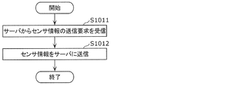
- FIG. 32 is a flowchart of sensor information transmission processing by the client device according to the sixth embodiment.
- FIG. 33 is a flowchart of three-dimensional data creation processing by the server according to the sixth embodiment.
- FIG. 34 is a flowchart of the three-dimensional map transmission process by the server according to the sixth embodiment.
- FIG. 35 is a diagram illustrating a configuration of a modified example of the system according to the sixth embodiment.
- FIG. 36 is a diagram illustrating configurations of a server and a client device according to the sixth embodiment.
- FIG. 37 is a block diagram of the three-dimensional data encoding apparatus according to the seventh embodiment.
- FIG. 38 is a diagram illustrating an example of the prediction residual according to the seventh embodiment.
- FIG. 39 is a diagram illustrating an example of a volume according to the seventh embodiment.
- FIG. 40 is a diagram illustrating an example of an octree representation of a volume according to the seventh embodiment.
- FIG. 41 is a diagram illustrating an example of a bit string of a volume according to the seventh embodiment.
- FIG. 42 is a diagram illustrating an example of an octree representation of a volume according to the seventh embodiment.
- FIG. 43 is a diagram illustrating an example of a volume according to the seventh embodiment.
- FIG. 44 is a diagram for describing intra prediction processing according to the seventh embodiment.
- FIG. 45 is a diagram for explaining rotation and translation processing according to the seventh embodiment.
- FIG. 46 is a diagram illustrating a syntax example of the RT application flag and the RT information according to the seventh embodiment.
- FIG. 47 is a diagram for explaining inter prediction processing according to Embodiment 7.
- FIG. 48 is a block diagram of the three-dimensional data decoding apparatus according to the seventh embodiment.
- FIG. 49 is a flowchart of three-dimensional data encoding processing by the three-dimensional data encoding device according to Embodiment 7.
- FIG. 50 is a flowchart of the 3D data decoding process performed by the 3D data decoding apparatus according to the seventh embodiment.
- FIG. 51 is a diagram illustrating a configuration of a distribution system according to the eighth embodiment.
- FIG. 52 is a diagram illustrating a configuration example of a bit stream of an encoded 3D map according to the eighth embodiment.
- FIG. 53 is a diagram for explaining the improvement effect of the coding efficiency according to the eighth embodiment.
- FIG. 54 is a flowchart of processing by the server according to Embodiment 8.
- FIG. 54 is a flowchart of processing by the server according to Embodiment 8.
- FIG. 55 is a flowchart of processing by a client according to the eighth embodiment.
- FIG. 56 is a diagram illustrating a syntax example of a submap according to the eighth embodiment.
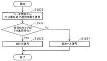
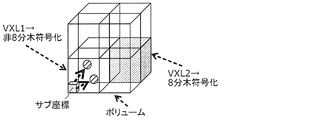
- FIG. 57 is a diagram schematically illustrating a coding type switching process according to the eighth embodiment.
- FIG. 58 is a diagram illustrating a syntax example of a submap according to the eighth embodiment.
- FIG. 59 is a flowchart of the three-dimensional data encoding process according to the eighth embodiment.
- FIG. 60 is a flowchart of the three-dimensional data decoding process according to the eighth embodiment.
- FIG. 61 is a diagram schematically illustrating an operation of a modification of the coding type switching process according to the eighth embodiment.
- FIG. 62 is a diagram schematically illustrating an operation of a modification of the coding type switching process according to the eighth embodiment.
- FIG. 63 is a diagram schematically illustrating an operation of a modification of the coding type switching process according to the eighth embodiment.
- FIG. 64 is a diagram schematically illustrating an operation of a modification of the difference value calculation process according to the eighth embodiment.
- FIG. 65 is a diagram schematically illustrating an operation of a modification of the difference value calculation process according to the eighth embodiment.
- FIG. 66 is a diagram schematically illustrating an operation of a modification of the difference value calculation process according to the eighth embodiment.
- FIG. 67 is a diagram schematically illustrating an operation of a modification of the difference value calculation process according to the eighth embodiment.
- FIG. 68 is a diagram showing a syntax example of a volume according to the eighth embodiment.
- FIG. 69 is a diagram illustrating an example of an important region according to the ninth embodiment.
- FIG. 70 is a diagram illustrating an example of an occupancy code according to the ninth embodiment.
- FIG. 71 is a diagram illustrating an example of a quadtree structure according to the ninth embodiment.
- FIG. 72 is a diagram illustrating an example of an occupancy code and a location code according to the ninth embodiment.
- FIG. 73 is a diagram illustrating an example of a three-dimensional point obtained by LiDAR according to the ninth embodiment.
- FIG. 74 is a diagram illustrating an example of an octree structure according to the ninth embodiment.
- FIG. 75 is a diagram illustrating an example of mixed coding according to Embodiment 9.
- FIG. 76 is a diagram for explaining a method of switching between location coding and occupancy coding according to Embodiment 9.
- FIG. 77 is a diagram illustrating an example of a bit stream for location coding according to the ninth embodiment.
- FIG. 78 is a diagram illustrating an example of a mixed coding bitstream according to the ninth embodiment.
- FIG. 79 is a diagram showing a tree structure of an important three-dimensional point occupancy code according to the ninth embodiment.
- FIG. 80 is a diagram showing a tree structure of occupancy codes of non-important 3D points according to Embodiment 9.
- FIG. 81 is a diagram illustrating an example of a mixed-encoding bitstream according to the ninth embodiment.
- FIG. 82 is a diagram illustrating an example of a bitstream including coding mode information according to Embodiment 9.
- FIG. 83 is a diagram illustrating a syntax example according to the ninth embodiment.
- FIG. 84 is a flowchart of the encoding process according to the ninth embodiment.
- FIG. 85 is a flowchart of node encoding processing according to the ninth embodiment.
- FIG. 86 is a flowchart of decoding processing according to Embodiment 9.
- FIG. 87 is a flowchart of node decoding processing according to the ninth embodiment.
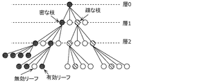
- FIG. 88 is a diagram illustrating an example of a tree structure according to the tenth embodiment.
- FIG. 89 is a diagram illustrating an example of the number of effective leaves included in each branch according to the tenth embodiment.
- FIG. 90 is a diagram illustrating an example of application of the coding scheme according to Embodiment 10.
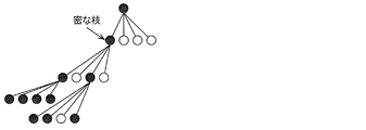
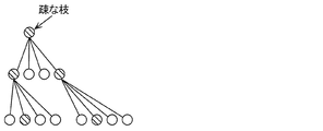
- FIG. 91 is a diagram illustrating an example of a dense branch region according to the tenth embodiment.
- FIG. 92 is a diagram showing an example of a dense three-dimensional point group according to the tenth embodiment.
- FIG. 93 is a diagram showing an example of a sparse three-dimensional point group according to the tenth embodiment.
- FIG. 94 is a flowchart of the encoding process according to the tenth embodiment.
- FIG. 95 is a flowchart of decoding processing according to Embodiment 10.
- FIG. 96 is a flowchart of the encoding process according to the tenth embodiment.
- FIG. 97 is a flowchart of decoding processing according to the tenth embodiment.
- FIG. 98 is a flowchart of the encoding process according to the tenth embodiment.
- FIG. 99 is a flowchart of decoding processing according to the tenth embodiment.
- FIG. 100 is a flowchart of three-dimensional point separation processing according to the tenth embodiment.
- FIG. 101 is a diagram illustrating a syntax example according to the tenth embodiment.
- FIG. 102 is a diagram illustrating an example of dense branches according to the tenth embodiment.
- FIG. 103 is a diagram illustrating an example of sparse branches according to the tenth embodiment.
- FIG. 104 is a flowchart of the encoding process according to the modification of the tenth embodiment.
- FIG. 105 is a flowchart of decoding processing according to a modification of the tenth embodiment.
- FIG. 106 is a flowchart of three-dimensional point separation processing according to a modification of the tenth embodiment.
- FIG. 107 is a diagram illustrating a syntax example according to a modification of the tenth embodiment.
- FIG. 108 is a flowchart of the encoding process according to the tenth embodiment.
- FIG. 109 is a flowchart of decoding processing according to Embodiment 10.
- FIG. 110 is a diagram illustrating an example of a tree structure according to the eleventh embodiment.
- FIG. 111 is a diagram illustrating an example of an occupancy code according to the eleventh embodiment.
- FIG. 112 is a diagram schematically illustrating an operation of the three-dimensional data encoding device according to the eleventh embodiment.
- FIG. 113 is a diagram showing an example of the geometric information according to the eleventh embodiment.
- FIG. 114 is a diagram illustrating an example of selecting an encoding table using geometric information according to Embodiment 11.
- FIG. 115 is a diagram showing a selection example of the coding table using the structure information according to the eleventh embodiment.
- FIG. 116 is a diagram illustrating an example of selecting an encoding table using attribute information according to Embodiment 11.
- FIG. 117 is a diagram illustrating an example of selecting an encoding table using attribute information according to the eleventh embodiment.
- FIG. 118 is a diagram illustrating a configuration example of a bit stream according to the eleventh embodiment.
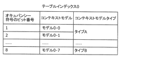
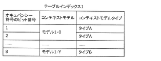
- FIG. 119 is a diagram illustrating an example of an encoding table according to Embodiment 11.
- 120 is a diagram illustrating an example of an encoding table according to Embodiment 11.
- FIG. 121 is a diagram illustrating a configuration example of a bitstream according to the eleventh embodiment.
- FIG. 122 is a diagram illustrating an example of an encoding table according to Embodiment 11.
- FIG. 123 is a diagram illustrating an example of an encoding table according to Embodiment 11.
- FIG. 124 is a diagram illustrating an example of the bit number of the occupancy code according to the eleventh embodiment.
- FIG. 125 is a flowchart of an encoding process using geometric information according to Embodiment 11.
- FIG. 126 is a flowchart of decoding processing using geometric information according to Embodiment 11.
- FIG. 127 is a flowchart of the encoding process using the structure information according to the eleventh embodiment.
- FIG. 128 is a flowchart of decoding processing using structure information according to Embodiment 11.
- FIG. 129 is a flowchart of encoding processing using attribute information according to Embodiment 11.
- FIG. 130 is a flowchart of decoding processing using attribute information according to Embodiment 11.
- FIG. 131 is a flowchart of a coding table selection process using geometric information according to Embodiment 11.
- FIG. 132 is a flowchart of a coding table selection process using structure information according to Embodiment 11.
- FIG. 133 is a flowchart of an encoding table selection process using attribute information according to Embodiment 11.
- FIG. 134 is a block diagram of a 3D data encoding apparatus according to Embodiment 11.
- FIG. 135 is a block diagram of the 3D data decoding apparatus according to Embodiment 11.
- FIG. FIG. 136 is a diagram illustrating a reference relationship in the octree structure according to the twelfth embodiment.
- FIG. 137 is a diagram showing a reference relationship in the space area according to the twelfth embodiment.
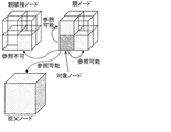
- 138 is a diagram illustrating an example of adjacent reference nodes according to Embodiment 12.
- FIG. FIG. 139 is a diagram illustrating a relationship between a parent node and a node according to the twelfth embodiment.
- FIG. 140 is a diagram illustrating an example of the occupancy code of the parent node according to the twelfth embodiment.
- FIG. 141 is a block diagram of a 3D data encoding apparatus according to Embodiment 12.
- FIG. 142 is a block diagram of a 3D data decoding apparatus according to Embodiment 12.
- FIG. 143 is a flowchart of 3D data encoding processing according to Embodiment 12.
- FIG. 144 is a flowchart of the three-dimensional data decoding process according to the twelfth embodiment.
- FIG. 145 is a diagram illustrating an example of coding table switching according to the twelfth embodiment.
- FIG. 146 is a diagram illustrating a reference relationship in the space area according to the first modification of the twelfth embodiment.
- FIG. 147 is a diagram illustrating a syntax example of the header information according to the first modification of the twelfth embodiment.
- FIG. 148 is a diagram illustrating a syntax example of the header information according to the first modification of the twelfth embodiment.
- FIG. 149 is a diagram illustrating an example of adjacent reference nodes according to the second modification of the twelfth embodiment.
- FIG. 150 is a diagram illustrating examples of target nodes and adjacent nodes according to the second modification of the twelfth embodiment.
- FIG. 151 is a diagram showing a reference relationship in the octree structure according to the third modification of the twelfth embodiment.
- FIG. 152 is a diagram showing a reference relationship in the space area according to the third modification of the twelfth embodiment.
- a 3D data encoding method encodes information on a target node included in a N (N is an integer of 2 or more) binary tree structure of a plurality of 3D points included in 3D data,
- N is an integer of 2 or more
- Reference to information on the second node is prohibited.
- the 3D data encoding method is encoded by referring to the information of the first node having the same parent node as the target node among a plurality of adjacent nodes spatially adjacent to the target node. Efficiency can be improved.
- the 3D data encoding method can reduce the processing amount by not referring to the information of the second node having a different parent node from the target node among a plurality of adjacent nodes.
- the three-dimensional data encoding method can improve encoding efficiency and reduce the processing amount.
- the three-dimensional data encoding method further determines whether to prohibit the reference of the information of the second node, and the encoding determines whether the information of the second node is based on the determination result.
- the three-dimensional data encoding method further switches prohibition or permission of reference, and the three-dimensional data encoding method further indicates prohibition switching information indicating whether or not reference of the information of the second node is prohibited as a result of the determination. May be generated.
- the 3D data encoding method can switch whether or not to prohibit the reference to the information of the second node. Further, the three-dimensional data decoding apparatus can appropriately perform the decoding process using the prohibition switching information.
- the information on the target node is information indicating whether a three-dimensional point exists in each of the child nodes belonging to the target node, and the information on the first node is three-dimensional on the first node. It is information indicating whether or not a point exists, and the information on the second node may be information indicating whether or not a three-dimensional point exists on the second node.
- an encoding table is selected based on whether or not a three-dimensional point exists in the first node, and the information of the target node is entropy encoded using the selected encoding table. May be used.
- reference to information of a child node of the first node among the plurality of adjacent nodes may be permitted.
- the three-dimensional data encoding method can refer to more detailed information of adjacent nodes, the encoding efficiency can be improved.
- a reference adjacent node among the plurality of adjacent nodes may be switched according to a spatial position in a parent node of the target node.
- the 3D data encoding method can refer to an appropriate adjacent node according to the spatial position in the parent node of the target node.
- a 3D data decoding method decodes information on a target node included in a N (N is an integer of 2 or more) branch tree structure of a plurality of 3D points included in 3D data,
- N is an integer of 2 or more
- the reference of the information of the first node having the same parent node as the target node among the plurality of adjacent nodes spatially adjacent to the target node is permitted, and the second is different from the target node and the parent node. Prohibits reference to node information.
- the three-dimensional data decoding method performs coding efficiency by referring to information of a first node having the same parent node as the target node among a plurality of adjacent nodes spatially adjacent to the target node. Can be improved.
- the three-dimensional data decoding method can reduce the processing amount by not referring to the information of the second node having a different parent node from the target node among the plurality of adjacent nodes.
- the three-dimensional data decoding method can improve the encoding efficiency and reduce the processing amount.
- the three-dimensional data decoding method further obtains prohibition switching information indicating whether or not reference to the information of the second node is prohibited from the bitstream, and in the decoding, based on the prohibition switching information, You may switch whether the reference of the information of a 2nd node is prohibited or permitted.
- the three-dimensional data decoding method can appropriately perform the decoding process using the prohibition switching information.
- the information on the target node is information indicating whether a three-dimensional point exists in each of the child nodes belonging to the target node, and the information on the first node is three-dimensional on the first node. It is information indicating whether or not a point exists, and the information on the second node may be information indicating whether or not a three-dimensional point exists on the second node.
- an encoding table is selected based on whether or not a three-dimensional point exists in the first node, and the information of the target node is entropy-decoded using the selected encoding table. May be.
- reference to information of a child node of the first node among the plurality of adjacent nodes may be permitted.
- the three-dimensional data decoding method can refer to more detailed information of adjacent nodes, the encoding efficiency can be improved.
- an adjacent node to be referred to may be switched among the plurality of adjacent nodes according to a spatial position in the parent node of the target node.
- the 3D data decoding method can refer to an appropriate adjacent node according to the spatial position in the parent node of the target node.
- a 3D data encoding apparatus includes a processor and a memory, and the processor uses the memory to calculate N (N of a plurality of 3D points included in the 3D data. Is an integer greater than or equal to 2) information of the target node included in the branch tree structure is encoded, and in the encoding, the target node and the parent node are the same among a plurality of adjacent nodes spatially adjacent to the target node.
- the reference of information of a certain first node is permitted, and the reference of information of a second node having a parent node different from the target node is prohibited.
- the 3D data encoding apparatus performs encoding by referring to the information of the first node having the same parent node as the target node among a plurality of adjacent nodes spatially adjacent to the target node. Efficiency can be improved.
- the 3D data encoding apparatus can reduce the processing amount by not referring to the information of the second node, which is different from the target node and the parent node, among the plurality of adjacent nodes.
- the three-dimensional data encoding apparatus can improve the encoding efficiency and reduce the processing amount.
- a 3D data decoding apparatus includes a processor and a memory, and the processor uses the memory to add N (N is a number of 3D points included in the 3D data). (An integer greater than or equal to 2) information on the target node included in the branch tree structure is decoded, and in the decoding, the target node and the parent node are the same among the plurality of adjacent nodes spatially adjacent to the target node. The reference of information of one node is permitted, and the reference of information of a second node having a different parent node from the target node is prohibited.
- the 3D data decoding apparatus refers to the encoding efficiency by referring to the information of the first node having the same parent node as the target node among a plurality of adjacent nodes spatially adjacent to the target node. Can be improved.
- the 3D data decoding apparatus can reduce the processing amount by not referring to the information of the second node having a different parent node from the target node among the plurality of adjacent nodes. As described above, the three-dimensional data decoding apparatus can improve the encoding efficiency and reduce the processing amount.
- FIG. 1 is a diagram showing a configuration of encoded three-dimensional data according to the present embodiment.
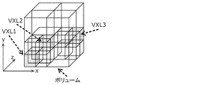
- the three-dimensional space is divided into spaces (SPC) corresponding to pictures in coding of moving images, and three-dimensional data is coded in units of spaces.
- the space is further divided into volumes (VLM) corresponding to macroblocks or the like in video encoding, and prediction and conversion are performed in units of VLM.
- the volume includes a plurality of voxels (VXL) that are minimum units with which position coordinates are associated.
- prediction is similar to the prediction performed in a two-dimensional image, refers to other processing units, generates predicted three-dimensional data similar to the processing unit to be processed, and generates the predicted three-dimensional data and the processing target.
- the difference from the processing unit is encoded.
- This prediction includes not only spatial prediction that refers to other prediction units at the same time but also temporal prediction that refers to prediction units at different times.
- a three-dimensional data encoding device (hereinafter also referred to as an encoding device) encodes a three-dimensional space represented by point cloud data such as a point cloud
- a point cloud is selected according to the voxel size. Or a plurality of points included in a voxel are collectively encoded. If the voxel is subdivided, the three-dimensional shape of the point cloud can be expressed with high accuracy, and if the voxel size is increased, the three-dimensional shape of the point cloud can be roughly expressed.
- the three-dimensional data is a point cloud
- the three-dimensional data is not limited to the point cloud, and may be three-dimensional data in an arbitrary format.
- hierarchical voxels may be used.
- n-th layer it may be indicated in order whether or not the sample points are present in the n-1 and lower layers (lower layers of the n-th layer). For example, when decoding only the n-th layer, if there is a sample point in the (n ⁇ 1) th or lower layer, it can be decoded assuming that the sample point exists at the center of the voxel in the n-th layer.
- the encoding apparatus acquires point cloud data using a distance sensor, a stereo camera, a monocular camera, a gyroscope, an inertial sensor, or the like.
- Spaces can be decoded independently, such as intra-space (I-SPC), predictive space (P-SPC) that can only be unidirectionally referenced, and bi-directional references. Classified into any one of at least three prediction structures including a large bi-directional space (B-SPC).
- the space has two types of time information, a decoding time and a display time.
- GOS Group Of Space
- WLD world
- the space area occupied by the world is associated with the absolute position on the earth by GPS or latitude and longitude information. This position information is stored as meta information.
- the meta information may be included in the encoded data or may be transmitted separately from the encoded data.
- all SPCs may be adjacent three-dimensionally, or there may be SPCs that are not three-dimensionally adjacent to other SPCs.
- processing such as encoding, decoding, or referring to three-dimensional data included in a processing unit such as GOS, SPC, or VLM is also simply referred to as encoding, decoding, or referencing the processing unit.
- the three-dimensional data included in the processing unit includes at least one set of a spatial position such as three-dimensional coordinates and a characteristic value such as color information.
- a plurality of SPCs in the same GOS or a plurality of VLMs in the same SPC occupy different spaces, but have the same time information (decoding time and display time).
- the first SPC in the decoding order in GOS is I-SPC.
- GOS There are two types of GOS: closed GOS and open GOS.
- the closed GOS is a GOS that can decode all SPCs in the GOS when decoding is started from the head I-SPC.
- the open GOS some SPCs whose display time is earlier than the first I-SPC in the GOS refer to different GOS, and decoding cannot be performed only by the GOS.
- WLD may be decoded from the reverse direction to the encoding order, and reverse reproduction is difficult if there is a dependency between GOS. Therefore, in such a case, a closed GOS is basically used.
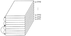
- GOS has a layer structure in the height direction, and encoding or decoding is performed in order from the SPC of the lower layer.
- FIG. 2 is a diagram showing an example of a prediction structure between SPCs belonging to the lowest layer of GOS.
- FIG. 3 is a diagram illustrating an example of a prediction structure between layers.
- I-SPCs there are one or more I-SPCs in GOS.
- objects such as humans, animals, cars, bicycles, traffic lights, and buildings that are landmarks in the three-dimensional space, but it is particularly effective to encode an object having a small size as I-SPC.
- a three-dimensional data decoding device (hereinafter also referred to as a decoding device) decodes only the I-SPC in the GOS when decoding the GOS with a low throughput or high speed.
- the encoding device may switch the encoding interval or appearance frequency of the I-SPC according to the density of the objects in the WLD.
- the encoding device or the decoding device encodes or decodes a plurality of layers in order from the lower layer (layer 1). Thereby, for example, the priority of data near the ground with a larger amount of information can be increased for an autonomous vehicle or the like.
- encoded data used in a drone or the like may be encoded or decoded in order from the SPC of the upper layer in the height direction in the GOS.
- the encoding device or decoding device may encode or decode a plurality of layers so that the decoding device can roughly grasp GOS and gradually increase the resolution.
- the encoding device or the decoding device may encode or decode in the order of layers 3, 8, 1, 9.
- static objects or scenes such as buildings or roads
- dynamic objects such as cars or humans
- Object detection is performed separately by extracting feature points from point cloud data or camera images such as a stereo camera.
- the first method is a method of encoding without distinguishing between static objects and dynamic objects.
- the second method is a method of discriminating between static objects and dynamic objects based on identification information.
- GOS is used as the identification unit.
- the GOS including the SPC configuring the static object and the GOS including the SPC configuring the dynamic object are distinguished by the identification information stored in the encoded data or separately from the encoded data.
- SPC may be used as an identification unit.
- the SPC that includes the VLM that configures the static object and the SPC that includes the VLM that configures the dynamic object are distinguished by the identification information.
- VLM or VXL may be used as the identification unit.
- a VLM or VXL including a static object and a VLM or VXL including a dynamic object are distinguished by the identification information.
- the encoding device may encode the dynamic object as one or more VLMs or SPCs, and may encode the VLM or SPC including the static object and the SPC including the dynamic object as different GOSs. Also, when the GOS size is variable according to the size of the dynamic object, the encoding apparatus separately stores the GOS size as meta information.
- the encoding device may encode the static object and the dynamic object independently of each other and superimpose the dynamic object on the world composed of the static objects.
- the dynamic object is composed of one or more SPCs, and each SPC is associated with one or more SPCs constituting a static object on which the SPC is superimposed.
- a dynamic object may be represented by one or more VLMs or VXLs instead of SPCs.
- the encoding device may encode the static object and the dynamic object as different streams.
- the encoding device may generate a GOS including one or more SPCs that constitute a dynamic object. Further, the encoding apparatus may set the GOS (GOS_M) including the dynamic object and the GOS of the static object corresponding to the GOS_M space area to the same size (occupy the same space area). Thereby, a superimposition process can be performed per GOS.
- GOS including one or more SPCs that constitute a dynamic object.
- the encoding apparatus may set the GOS (GOS_M) including the dynamic object and the GOS of the static object corresponding to the GOS_M space area to the same size (occupy the same space area). Thereby, a superimposition process can be performed per GOS.
- the P-SPC or B-SPC constituting the dynamic object may refer to the SPC included in a different encoded GOS.
- the reference across the GOS is effective from the viewpoint of the compression rate.
- the first method and the second method may be switched according to the use of the encoded data. For example, when using encoded 3D data as a map, it is desirable to be able to separate dynamic objects, and therefore the encoding apparatus uses the second method. On the other hand, the encoding apparatus uses the first method when it is not necessary to separate dynamic objects when encoding three-dimensional data of events such as concerts or sports.
- the GOS or SPC decoding time and display time can be stored in the encoded data or as meta information. Moreover, all the time information of static objects may be the same. At this time, the actual decoding time and display time may be determined by the decoding device. Alternatively, a different value may be given as the decoding time for each GOS or SPC, and the same value may be given as the display time. Furthermore, like a decoder model in moving picture coding such as HEVC's HRD (Hypothetical Reference Decoder), the decoder has a buffer of a predetermined size and can be decoded without failure if a bit stream is read at a predetermined bit rate according to the decoding time. You may introduce a model that guarantees
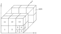
- the coordinates of the three-dimensional space in the world are expressed by three coordinate axes (x axis, y axis, z axis) orthogonal to each other.
- encoding can be performed so that spatially adjacent GOSs are continuous in the encoded data.
- GOS in the xz plane is continuously encoded.
- the value of the y-axis is updated after encoding of all GOSs in a certain xz plane is completed. That is, as encoding progresses, the world extends in the y-axis direction.
- the GOS index number is set in the encoding order.
- the three-dimensional space of the world is associated with GPS or geographical absolute coordinates such as latitude and longitude in one-to-one correspondence.
- the three-dimensional space may be expressed by a relative position from a preset reference position.
- the x-axis, y-axis, and z-axis directions in the three-dimensional space are expressed as direction vectors determined based on latitude and longitude, and the direction vectors are stored as meta information together with the encoded data.
- the GOS size is fixed, and the encoding device stores the size as meta information. Further, the size of the GOS may be switched depending on, for example, whether it is an urban area or whether it is indoor or outdoor. That is, the size of the GOS may be switched according to the amount or nature of the object that is valuable as information. Alternatively, the encoding device may adaptively switch the GOS size or the I-SPC interval in the GOS in accordance with the object density or the like in the same world. For example, the higher the object density, the smaller the size of the GOS and the shorter the I-SPC interval in the GOS.
- the density of objects is high, so that the GOS is subdivided in order to realize random access with fine granularity.
- the seventh to tenth GOS exist on the back side of the third to sixth GOS, respectively.
- FIG. 6 is a block diagram of 3D data encoding apparatus 100 according to the present embodiment.
- FIG. 7 is a flowchart showing an operation example of the three-dimensional data encoding apparatus 100.
- the three-dimensional data encoding device 100 shown in FIG. 6 generates encoded three-dimensional data 112 by encoding the three-dimensional data 111.
- the three-dimensional data encoding apparatus 100 includes an acquisition unit 101, an encoding region determination unit 102, a division unit 103, and an encoding unit 104.
- the acquisition unit 101 first acquires three-dimensional data 111 that is point cloud data (S101).
- the coding area determination unit 102 determines a coding target area among the spatial areas corresponding to the acquired point cloud data (S102). For example, the coding area determination unit 102 determines a space area around the position as a coding target area according to the position of the user or the vehicle.
- the dividing unit 103 divides the point cloud data included in the encoding target area into each processing unit.
- the processing unit is the above-described GOS, SPC, or the like.
- this encoding target area corresponds to the above-described world, for example.
- the dividing unit 103 divides the point cloud data into processing units based on a preset GOS size or the presence or size of a dynamic object (S103). Further, the dividing unit 103 determines the start position of the SPC that is the head in the encoding order in each GOS.
- the encoding unit 104 generates encoded three-dimensional data 112 by sequentially encoding a plurality of SPCs in each GOS (S104).
- the three-dimensional data encoding device 100 generates the encoded three-dimensional data 112 by encoding the three-dimensional data 111.
- the 3D data encoding apparatus 100 divides 3D data into first processing units (GOS) each of which is a random access unit and is associated with 3D coordinates.
- the processing unit (GOS) is divided into a plurality of second processing units (SPC), and the second processing unit (SPC) is divided into a plurality of third processing units (VLM).
- the third processing unit (VLM) includes one or more voxels (VXL) that are minimum units with which position information is associated.
- the three-dimensional data encoding device 100 generates encoded three-dimensional data 112 by encoding each of the plurality of first processing units (GOS). Specifically, the three-dimensional data encoding device 100 encodes each of the plurality of second processing units (SPC) in each first processing unit (GOS). In addition, the 3D data encoding apparatus 100 encodes each of the plurality of third processing units (VLM) in each second processing unit (SPC).
- GOS first processing unit
- VLM third processing units
- the 3D data encoding apparatus 100 has the second processing unit to be processed included in the first processing unit (GOS) to be processed.
- SPC is encoded with reference to another second processing unit (SPC) included in the first processing unit (GOS) to be processed. That is, the 3D data encoding apparatus 100 does not refer to the second processing unit (SPC) included in the first processing unit (GOS) different from the first processing unit (GOS) to be processed.
- the processing target second processing unit (SPC) included in the processing target first processing unit (GOS) is set as the processing target first processing unit (GOS).
- the 3D data encoding apparatus 100 uses the first type (I-SPC) that does not refer to another second processing unit (SPC) as the type of the second processing unit (SPC) to be processed, Select either the second type (P-SPC) that refers to the second processing unit (SPC) or the third type that refers to the other two second processing units (SPC), and process according to the selected type
- the target second processing unit (SPC) is encoded.
- FIG. 8 is a block diagram of a block of 3D data decoding apparatus 200 according to the present embodiment.
- FIG. 9 is a flowchart showing an operation example of the three-dimensional data decoding apparatus 200.
- the 3D data decoding apparatus 200 shown in FIG. 8 generates decoded 3D data 212 by decoding the encoded 3D data 211.
- the encoded three-dimensional data 211 is, for example, the encoded three-dimensional data 112 generated by the three-dimensional data encoding device 100.
- the three-dimensional data decoding apparatus 200 includes an acquisition unit 201, a decoding start GOS determination unit 202, a decoding SPC determination unit 203, and a decoding unit 204.
- the acquisition unit 201 acquires the encoded three-dimensional data 211 (S201).
- the decoding start GOS determination unit 202 determines a GOS to be decoded (S202). Specifically, the decoding start GOS determination unit 202 refers to the meta information stored in the encoded 3D data 211 or separately from the encoded 3D data, and the spatial position, object, or The GOS including the SPC corresponding to the time is determined as the GOS to be decrypted.
- the decoding SPC determination unit 203 determines the type (I, P, B) of SPC to be decoded in the GOS (S203). For example, the decoding SPC determination unit 203 determines whether (1) only I-SPC is decoded, (2) I-SPC and P-SPC are decoded, or (3) all types are decoded. Note that this step may not be performed if the type of SPC to be decoded has been determined in advance, such as decoding all SPCs.
- the decoding unit 204 acquires an address position where the head SPC in the decoding order (same as the coding order) in the GOS starts in the encoded three-dimensional data 211, and the code of the first SPC from the address position.
- the data is acquired, and each SPC is sequentially decoded from the head SPC (S204).
- the address position is stored in meta information or the like.
- the three-dimensional data decoding apparatus 200 decodes the decoded three-dimensional data 212. Specifically, the three-dimensional data decoding apparatus 200 decodes each of the encoded three-dimensional data 211 of the first processing unit (GOS) that is a random access unit and each is associated with a three-dimensional coordinate. Thus, the decoded three-dimensional data 212 of the first processing unit (GOS) is generated. More specifically, the three-dimensional data decoding apparatus 200 decodes each of the plurality of second processing units (SPC) in each first processing unit (GOS). The three-dimensional data decoding apparatus 200 decodes each of the plurality of third processing units (VLM) in each second processing unit (SPC).
- SPC second processing units
- VLM third processing units
- This meta information is generated by the three-dimensional data encoding apparatus 100 and is included in the encoded three-dimensional data 112 (211).
- FIG. 10 is a diagram illustrating an example of a table included in the meta information. Note that not all the tables shown in FIG. 10 need be used, and at least one table may be used.
- the address may be an address in a logical format or a physical address of an HDD or a memory.
- Information specifying a file segment may be used instead of an address.
- a file segment is a unit obtained by segmenting one or more GOSs.
- a plurality of GOSs to which the object belongs may be indicated in the object-GOS table. If the plurality of GOSs are closed GOS, the encoding device and the decoding device can perform encoding or decoding in parallel. On the other hand, if the plurality of GOSs are open GOS, the compression efficiency can be further improved by referring to the plurality of GOSs.
- the 3D data encoding apparatus 100 extracts a feature point specific to an object from a 3D point cloud or the like at the time of world encoding, detects an object based on the feature point, and detects the detected object as a random access point. Can be set as
- the three-dimensional data encoding apparatus 100 includes the first information indicating the plurality of first processing units (GOS) and the three-dimensional coordinates associated with each of the plurality of first processing units (GOS). Is generated. Also, the encoded three-dimensional data 112 (211) includes this first information. The first information further indicates at least one of the object, the time, and the data storage destination associated with each of the plurality of first processing units (GOS).
- the three-dimensional data decoding apparatus 200 acquires the first information from the encoded three-dimensional data 211, and uses the first information to encode the first processing unit corresponding to the specified three-dimensional coordinate, object, or time.
- the original data 211 is specified, and the encoded three-dimensional data 211 is decoded.
- the three-dimensional data encoding apparatus 100 may generate and store the following meta information. Further, the three-dimensional data decoding apparatus 200 may use this meta information at the time of decoding.
- a profile may be defined according to the application, and information indicating the profile may be included in the meta information. For example, profiles for urban areas, suburbs, or flying objects are defined, and the maximum or minimum size of the world, SPC, or VLM is defined in each profile. For example, in a city area, detailed information is required more than in a suburb area, so the minimum size of the VLM is set smaller.
- the meta information may include a tag value indicating the type of object.
- This tag value is associated with the VLM, SPC, or GOS constituting the object. For example, the tag value “0” indicates “person”, the tag value “1” indicates “car”, the tag value “2” indicates “traffic light”, and the like. Also good.
- a tag value indicating a size or a property such as a dynamic object or a static object may be used.
- the meta information may include information indicating the range of the space area occupied by the world.
- the meta information may store the SPC or VXL size as header information common to a plurality of SPCs such as the entire encoded data stream or SPC in GOS.
- the meta information may include identification information such as a distance sensor or a camera used for generating the point cloud, or information indicating the position accuracy of the point cloud in the point cloud.
- the meta information may include information indicating whether the world is composed of only static objects or includes dynamic objects.
- the encoding device or decoding device may encode or decode two or more different SPCs or GOSs in parallel.
- the GOS to be encoded or decoded in parallel can be determined based on meta information indicating the spatial position of the GOS.
- the encoding device or the decoding device uses GPS, route information, zoom magnification, etc. You may encode or decode GOS or SPC included in the space specified based on it.
- the decoding device may perform decoding in order from a space close to the self-position or the travel route.
- the encoding device or the decoding device may encode or decode a space far from its own position or travel route with a lower priority than a close space.
- lowering the priority means lowering the processing order, lowering the resolution (processing by thinning out), or lowering the image quality (increasing encoding efficiency, for example, increasing the quantization step).
- the decoding device may decode only the lower layer when decoding the encoded data that is hierarchically encoded in the space.
- the decoding device may decode preferentially from the lower hierarchy according to the zoom magnification or use of the map.
- the encoding device or the decoding device encodes with a resolution reduced except for an area within a specific height from the road surface (an area for recognition). Or decoding may be performed.
- the encoding device may individually encode the point clouds representing the indoor and outdoor space shapes. For example, by separating GOS (indoor GOS) representing the room and GOS (outdoor GOS) representing the room, the decoding device selects the GOS to be decoded according to the viewpoint position when using the encoded data. it can.
- the encoding device may encode the indoor GOS and the outdoor GOS having close coordinates so as to be adjacent in the encoded stream.
- the encoding apparatus associates both identifiers, and stores information indicating the identifiers associated with each other in the encoded stream or meta information stored separately.
- the decoding apparatus can identify the indoor GOS and the outdoor GOS whose coordinates are close by referring to the information in the meta information.
- the encoding device may switch the size of GOS or SPC between the indoor GOS and the outdoor GOS. For example, the encoding apparatus sets the size of GOS smaller in the room than in the outdoor. Further, the encoding device may change the accuracy when extracting feature points from the point cloud, the accuracy of object detection, or the like between the indoor GOS and the outdoor GOS.
- the encoding device may add information for the decoding device to display the dynamic object separately from the static object to the encoded data.
- the decoding apparatus can display a dynamic object and a red frame or explanatory characters together.
- the decoding device may display only a red frame or explanatory characters instead of the dynamic object.
- the decoding device may display a finer object type. For example, a red frame may be used for a car and a yellow frame may be used for a human.
- the encoding device or the decoding device encodes the dynamic object and the static object as different SPC or GOS according to the appearance frequency of the dynamic object or the ratio of the static object to the dynamic object. Or you may decide whether to decode. For example, when the appearance frequency or ratio of a dynamic object exceeds a threshold, SPC or GOS in which a dynamic object and a static object are mixed is allowed, and the appearance frequency or ratio of a dynamic object does not exceed the threshold Does not allow SPC or GOS in which dynamic objects and static objects are mixed.
- the encoding device When detecting a dynamic object from the two-dimensional image information of the camera instead of the point cloud, the encoding device separately acquires information for identifying the detection result (such as a frame or a character) and the object position, Such information may be encoded as part of the three-dimensional encoded data. In this case, the decoding device superimposes and displays auxiliary information (frame or character) indicating the dynamic object on the decoding result of the static object.
- auxiliary information frame or character
- the encoding device may change the density of VXL or VLM in the SPC according to the complexity of the shape of the static object. For example, the encoding device sets VXL or VLM more densely as the shape of the static object is more complicated. Further, the encoding apparatus may determine a quantization step or the like when quantizing the spatial position or color information according to the density of VXL or VLM. For example, the encoding apparatus sets the quantization step to be smaller as VXL or VLM is denser.
- the encoding device or decoding device performs space encoding or decoding in units of space having coordinate information.
- the encoding device and the decoding device perform encoding or decoding in units of volume in the space.
- the volume includes a voxel that is a minimum unit with which position information is associated.
- the encoding device and the decoding device associate arbitrary elements using a table in which each element of spatial information including coordinates, objects, time, and the like is associated with a GOP, or a table in which elements are associated with each other. Encoding or decoding.
- the decoding apparatus determines coordinates using the value of the selected element, specifies a volume, voxel, or space from the coordinates, and decodes the space including the volume or voxel or the specified space.
- the encoding device determines a volume, voxel, or space that can be selected by the element by feature point extraction or object recognition, and encodes it as a randomly accessible volume, voxel, or space.
- a space refers to an I-SPC that can be encoded or decoded by the space alone, a P-SPC that is encoded or decoded with reference to any one processed space, and any two processed spaces. Are classified into three types of B-SPC encoded or decoded.
- One or more volumes correspond to static objects or dynamic objects.
- a space including a static object and a space including a dynamic object are encoded or decoded as different GOS. That is, the SPC including the static object and the SPC including the dynamic object are assigned to different GOSs.
- a dynamic object is encoded or decoded for each object, and is associated with one or more spaces including static objects. That is, the plurality of dynamic objects are individually encoded, and the obtained encoded data of the plurality of dynamic objects is associated with the SPC including the static object.
- the encoding device and the decoding device increase the priority of I-SPC in GOS and perform encoding or decoding.
- the encoding apparatus performs encoding so that degradation of I-SPC is reduced (so that original three-dimensional data is reproduced more faithfully after decoding).
- the decoding device decodes only I-SPC, for example.
- the encoding device may perform encoding by changing the frequency of using I-SPC according to the density or number (quantity) of objects in the world. That is, the encoding device changes the frequency of selecting the I-SPC according to the number or density of objects included in the three-dimensional data. For example, the encoding device increases the frequency of using the I space as the objects in the world are denser.
- the encoding apparatus sets random access points in units of GOS, and stores information indicating the space area corresponding to GOS in the header information.
- the encoding device uses, for example, a default value as the GOS space size.
- the encoding device may change the size of the GOS according to the number (amount) or density of objects or dynamic objects. For example, the encoding device reduces the GOS space size as the objects or dynamic objects are denser or more numerous.
- the space or volume includes a feature point group derived using information obtained by a sensor such as a depth sensor, gyroscope, or camera.
- the coordinates of the feature point are set at the center position of the voxel. Further, high accuracy of position information can be realized by subdividing voxels.
- the feature point group is derived using a plurality of pictures.
- the plurality of pictures have at least two types of time information: actual time information and the same time information (for example, encoding time used for rate control) in the plurality of pictures associated with the space.
- encoding or decoding is performed in units of GOS including one or more spaces.
- the encoding device and the decoding device refer to the space in the processed GOS and predict the P space or B space in the processing target GOS.
- the encoding device and the decoding device do not refer to different GOS, and use the processed space in the processing target GOS to predict the P space or B space in the processing target GOS.
- the encoding device and the decoding device transmit or receive the encoded stream in units of world including one or more GOSs.
- GOS has a layer structure in at least one direction in the world, and the encoding device and the decoding device perform encoding or decoding from a lower layer.
- a randomly accessible GOS belongs to the lowest layer.
- GOS belonging to an upper layer refers to GOS belonging to the same layer or lower. That is, GOS includes a plurality of layers that are spatially divided in a predetermined direction and each include one or more SPCs.
- the encoding device and the decoding device encode or decode each SPC with reference to the SPC included in the same layer as the SPC or a layer lower than the SPC.
- the encoding device and the decoding device continuously encode or decode GOS within a world unit including a plurality of GOSs.
- the encoding device and the decoding device write or read information indicating the order (direction) of encoding or decoding as metadata. That is, the encoded data includes information indicating the encoding order of a plurality of GOSs.
- the encoding device and the decoding device encode or decode two or more different spaces or GOS in parallel.
- the encoding device and the decoding device encode or decode space or GOS space information (coordinates, size, etc.).
- the encoding device and the decoding device encode or decode a space or GOS included in a specific space that is specified based on external information related to its position or / and region size, such as GPS, route information, or magnification. .
- the encoding device or decoding device encodes or decodes a space far from its own position with a lower priority than a close space.
- the encoding apparatus sets a certain direction of the world according to the magnification or application, and encodes GOS having a layer structure in the direction. Further, the decoding apparatus preferentially decodes GOS having a layer structure in one direction of the world set according to the magnification or use from the lower layer.
- the encoding device changes the feature point included in the space, the accuracy of object recognition, or the size of the space area between the room and the room.
- the encoding device and the decoding device encode or decode the indoor GOS and the outdoor GOS whose coordinates are close to each other in the world, and encode or decode these identifiers in association with each other.
- a three-dimensional data encoding method and a three-dimensional data encoding device for providing a function of transmitting and receiving only necessary information according to applications in encoded data of a three-dimensional point cloud, and A 3D data decoding method and 3D data decoding apparatus for decoding encoded data will be described.
- FIG. 11 is a diagram illustrating a configuration example of a sparse world and a world.
- SWLD includes FGOS, which is a GOS composed of FVXL, FSPC, which is an SPC composed of FVXL, and FVLM, which is a VLM composed of FVXL.
- FGOS which is a GOS composed of FVXL
- FSPC which is an SPC composed of FVXL
- FVLM which is a VLM composed of FVXL.
- the data structure and prediction structure of FGOS, FSPC, and FVLM may be the same as those of GOS, SPC, and VLM.
- the feature amount is a feature amount that expresses VXL three-dimensional position information or visible light information of the VXL position, and is a feature amount that is often detected particularly at corners and edges of a three-dimensional object.
- this feature quantity is a three-dimensional feature quantity or visible light feature quantity as described below, but any other feature quantity that represents VXL position, luminance, color information, or the like can be used. It does n’t matter.
- a SHOT feature value Signature of Histograms of Orientations
- a PFH feature value Point Feature History
- a PPF feature value Point Pair Feature
- the SHOT feature value is obtained by dividing the periphery of the VXL, calculating the inner product of the reference point and the normal vector of the divided area, and generating a histogram.
- This SHOT feature amount has a feature that the number of dimensions is high and the feature expression power is high.
- the PFH feature value is obtained by selecting a large number of two-point sets in the vicinity of the VXL, calculating a normal vector from the two points, and forming a histogram. Since this PFH feature amount is a histogram feature, it has a feature that it has robustness against a certain amount of disturbance and has a high feature expression power.
- the PPF feature value is a feature value calculated using a normal vector or the like for each two VXL points. Since all VXL is used for this PPF feature quantity, it has robustness against occlusion.
- SIFT Scale-Invariant Feature Transform
- SURF Speeded Up Robust Features
- HOG Histogram of Oriented
- SWLD is generated by calculating the feature amount from each VXL of WLD and extracting FVXL.
- the SWLD may be updated every time the WLD is updated, or may be updated periodically after a certain period of time regardless of the update timing of the WLD.
- SWLD may be generated for each feature amount. For example, separate SWLDs may be generated for each feature quantity, such as SWLD1 based on SHOT feature quantity and SWLD2 based on SIFT feature quantity, and the SWLD may be used properly according to the application. Further, the calculated feature amount of each FVXL may be held in each FVXL as feature amount information.
- SWLD Sparse World
- the network bandwidth and transfer time can be suppressed by holding WLD and SWLD as map information in a server and switching the map information to be transmitted to WLD or SWLD in response to a request from a client. . Specific examples will be shown below.
- FIG. 12 and 13 are diagrams showing examples of using SWLD and WLD.
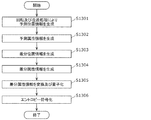
- the client 1 when the client 1 which is an in-vehicle device needs map information for the purpose of self-position determination, the client 1 sends a request for acquiring map data for self-position estimation to the server (S301).
- the server transmits the SWLD to the client 1 in response to the acquisition request (S302).
- the client 1 performs self-position determination using the received SWLD (S303).
- the client 1 acquires VXL information around the client 1 by various methods such as a distance sensor such as a range finder, a stereo camera, or a combination of a plurality of monocular cameras, and self-assembling from the obtained VXL information and SWLD.
- the self-position information includes the three-dimensional position information and orientation of the client 1.
- the client 2 which is an in-vehicle device needs map information for the purpose of drawing a map such as a three-dimensional map
- the client 2 sends a request for obtaining map data for map drawing to the server (S311). ).
- the server transmits a WLD to the client 2 in response to the acquisition request (S312).
- the client 2 performs map drawing using the received WLD (S313).
- the client 2 creates a rendering image using, for example, an image captured by itself with a visible light camera or the like and a WLD acquired from the server, and draws the created image on a screen such as a car navigation system.
- the server sends SWLD to the client for applications that mainly require the feature amount of each VXL such as self-position estimation, and WLD is used when detailed VXL information is required such as map drawing. Send to client. Thereby, it becomes possible to transmit / receive map data efficiently.
- the client may determine whether SWLD or WLD is necessary, and may request the server to send SWLD or WLD. Further, the server may determine whether to transmit SWLD or WLD according to the situation of the client or the network.
- SWLD sparse world
- WLD world
- FIG. 14 is a diagram showing an operation example in this case.
- a low-speed network with a limited network bandwidth such as in LTE (Long Term Evolution) environment
- the client accesses the server via the low-speed network (S321), and maps from the server.
- SWLD is acquired as information (S322).
- a high-speed network with sufficient network bandwidth such as in a Wi-Fi (registered trademark) environment
- the client accesses the server via the high-speed network (S323), and acquires the WLD from the server. (S324).
- the client can acquire suitable map information according to the network bandwidth of the client.
- the client receives the SWLD via LTE outdoors, and acquires the WLD via Wi-Fi (registered trademark) when entering a facility or the like indoors. As a result, the client can acquire more detailed map information indoors.
- Wi-Fi registered trademark
- the client may request WLD or SWLD from the server according to the network bandwidth used by the client.
- the client may transmit information indicating the network bandwidth used by the client to the server, and the server may transmit data (WLD or SWLD) suitable for the client according to the information.
- the server may determine the network bandwidth of the client and transmit data (WLD or SWLD) suitable for the client.
- FIG. 15 is a diagram illustrating an operation example in this case.
- the client when the client is moving at high speed (S331), the client receives SWLD from the server (S332).
- the client receives the WLD from the server (S334).
- the client can acquire map information matching the speed while suppressing the network bandwidth.
- the client can update rough map information at an appropriate speed by receiving a SWLD with a small amount of data while traveling on an expressway.
- the client can acquire more detailed map information by receiving the WLD while traveling on a general road.
- the client may request WLD or SWLD from the server according to its moving speed.
- the client may transmit information indicating its own moving speed to the server, and the server may transmit data (WLD or SWLD) suitable for the client according to the information.
- the server may determine the moving speed of the client and transmit data (WLD or SWLD) suitable for the client.
- the client may first acquire the SWLD from the server, and may acquire the WLD of an important area in the SWLD. For example, when acquiring map data, the client first acquires rough map information by SWLD, narrows down areas where many features such as buildings, signs, or people appear, and then narrows down the WLD of the narrowed area. Get it later. Thereby, the client can acquire detailed information on a necessary area while suppressing the amount of data received from the server.
- the server may create a separate SWLD for each object from the WLD, and the client may receive each according to the application. Thereby, a network band can be suppressed.
- the server recognizes a person or a car in advance from the WLD, and creates a human SWLD and a car SWLD.
- the client receives a person's SWLD if he wants to obtain information on people around him, and receives a car's SWLD if he wants to obtain car information.
- SWLD types may be distinguished by information (flag or type) added to a header or the like.
- FIG. 16 is a block diagram of 3D data encoding apparatus 400 according to the present embodiment.
- FIG. 17 is a flowchart of three-dimensional data encoding processing by the three-dimensional data encoding device 400.
- the 16 generates encoded 3D data 413 and 414, which are encoded streams, by encoding the input 3D data 411.
- the encoded 3D data 413 is encoded 3D data corresponding to WLD
- the encoded 3D data 414 is encoded 3D data corresponding to SWLD.
- the three-dimensional data encoding apparatus 400 includes an acquisition unit 401, an encoding region determination unit 402, a SWLD extraction unit 403, a WLD encoding unit 404, and a SWLD encoding unit 405.
- the acquisition unit 401 acquires input three-dimensional data 411 that is point cloud data in a three-dimensional space (S401).
- the coding area determination unit 402 determines a space area to be coded based on the space area where the point cloud data exists (S402).
- the SWLD extraction unit 403 defines a space area to be encoded as WLD, and calculates a feature amount from each VXL included in the WLD. Then, the SWLD extraction unit 403 extracts VXL whose feature amount is equal to or greater than a predetermined threshold, defines the extracted VXL as FVXL, and adds the FVXL to the SWLD, thereby generating extracted three-dimensional data 412. (S403). That is, extracted 3D data 412 having a feature amount equal to or greater than a threshold is extracted from the input 3D data 411.
- the WLD encoding unit 404 generates encoded three-dimensional data 413 corresponding to WLD by encoding the input three-dimensional data 411 corresponding to WLD (S404). At this time, the WLD encoding unit 404 adds information for distinguishing that the encoded three-dimensional data 413 is a stream including WLD to the header of the encoded three-dimensional data 413.
- the SWLD encoding unit 405 generates encoded three-dimensional data 414 corresponding to SWLD by encoding the extracted three-dimensional data 412 corresponding to SWLD (S405). At this time, the SWLD encoding unit 405 adds information for distinguishing that the encoded three-dimensional data 414 is a stream including SWLD to the header of the encoded three-dimensional data 414.
- processing order of the process of generating the encoded three-dimensional data 413 and the process of generating the encoded three-dimensional data 414 may be reverse to the above. Also, some or all of these processes may be performed in parallel.
- a parameter “world_type” is defined.
- a specific flag may be included in one of the encoded three-dimensional data 413 and 414. For example, a flag including that the stream includes SWLD may be assigned to the encoded three-dimensional data 414. In this case, the decoding apparatus can determine whether the stream includes WLD or SWLD depending on the presence or absence of a flag.
- the encoding method used when the WLD encoding unit 404 encodes WLD may be different from the encoding method used when the SWLD encoding unit 405 encodes SWLD.
- inter prediction may be prioritized among intra prediction and inter prediction over the encoding method used for WLD.
- the encoding method used for SWLD and the encoding method used for WLD may differ in the three-dimensional position representation method.
- the three-dimensional position of FVXL may be represented by three-dimensional coordinates
- WLD the three-dimensional position may be represented by an octree that will be described later, and vice versa.
- the SWLD encoding unit 405 performs encoding so that the data size of the encoded three-dimensional data 414 of SWLD is smaller than the data size of the encoded three-dimensional data 413 of WLD.
- SWLD may have a lower correlation between data than WLD.
- the encoding efficiency decreases, and the data size of the encoded three-dimensional data 414 may become larger than the data size of the encoded three-dimensional data 413 of WLD. Therefore, when the data size of the obtained encoded three-dimensional data 414 is larger than the data size of the encoded three-dimensional data 413 of the WLD, the SWLD encoding unit 405 performs re-encoding to thereby obtain the data size.
- the encoded three-dimensional data 414 with reduced is regenerated.
- the SWLD extraction unit 403 regenerates the extracted three-dimensional data 412 in which the number of feature points to be extracted is reduced, and the SWLD encoding unit 405 encodes the extracted three-dimensional data 412.
- the degree of quantization in the SWLD encoding unit 405 may be made coarser.
- the degree of quantization can be roughened by rounding the data in the lowest layer.
- the SWLD encoding unit 405 does not generate the SWLD encoded three-dimensional data 414. May be.
- the encoded 3D data 413 of WLD may be copied to the encoded 3D data 414 of SWLD. That is, the WLD encoded three-dimensional data 413 may be used as it is as the SWLD encoded three-dimensional data 414.
- FIG. 18 is a block diagram of 3D data decoding apparatus 500 according to the present embodiment.
- FIG. 19 is a flowchart of the 3D data decoding process performed by the 3D data decoding apparatus 500.
- the three-dimensional data decoding apparatus 500 shown in FIG. 18 generates decoded three-dimensional data 512 or 513 by decoding the encoded three-dimensional data 511.
- the encoded 3D data 511 is, for example, the encoded 3D data 413 or 414 generated by the 3D data encoding device 400.
- the 3D data decoding apparatus 500 includes an acquisition unit 501, a header analysis unit 502, a WLD decoding unit 503, and a SWLD decoding unit 504.
- the acquisition unit 501 acquires encoded three-dimensional data 511 (S501).
- the header analysis unit 502 analyzes the header of the encoded three-dimensional data 511 and determines whether the encoded three-dimensional data 511 is a stream including WLD or a stream including SWLD (S502). For example, the determination is performed with reference to the above-described parameter of type_type.
- the WLD decoding unit 503 When the encoded 3D data 511 is a stream including WLD (Yes in S503), the WLD decoding unit 503 generates the decoded 3D data 512 of WLD by decoding the encoded 3D data 511 (S504). . On the other hand, when the encoded three-dimensional data 511 is a stream including SWLD (No in S503), the SWLD decoding unit 504 generates the decoded three-dimensional data 513 of SWLD by decoding the encoded three-dimensional data 511 ( S505).
- the decoding method used when the WLD decoding unit 503 decodes WLD may be different from the decoding method used when the SWLD decoding unit 504 decodes SWLD.
- inter prediction may be prioritized among intra prediction and inter prediction over the decoding method used for WLD.
- the three-dimensional position representation method may be different between the decoding method used for SWLD and the decoding method used for WLD.
- the three-dimensional position of FVXL may be represented by three-dimensional coordinates
- WLD the three-dimensional position may be represented by an octree that will be described later, and vice versa.
- FIG. 20 is a diagram illustrating an example of VXL of WLD.
- FIG. 21 is a diagram showing an octree structure of the WLD shown in FIG. In the example shown in FIG. 20, there are three VXLs 1 to 3 that are VXLs including point clouds (hereinafter referred to as effective VXLs).
- the octree structure is composed of nodes and leaves. Each node has a maximum of 8 nodes or leaves. Each leaf has VXL information. Of the leaves shown in FIG. 21, leaves 1, 2, and 3 represent VXL1, VXL2, and VXL3 shown in FIG. 20, respectively.
- each node and leaf corresponds to a three-dimensional position.
- Node 1 corresponds to the entire block shown in FIG.
- the block corresponding to the node 1 is divided into eight blocks. Among the eight blocks, a block including the valid VXL is set as a node, and the other blocks are set as leaves.
- the block corresponding to the node is further divided into eight nodes or leaves, and this process is repeated for the hierarchy of the tree structure. In addition, all the lowermost blocks are set to leaves.
- FIG. 22 is a diagram showing an example of SWLD generated from the WLD shown in FIG. VXL1 and VXL2 shown in FIG. 20 are determined as FVXL1 and FVXL2 as a result of feature amount extraction, and are added to SWLD.
- VXL3 is not determined as FVXL and is not included in SWLD.
- FIG. 23 is a diagram illustrating the octree structure of the SWLD illustrated in FIG. In the octree structure shown in FIG. 23, leaf 3 corresponding to VXL3 shown in FIG. 21 is deleted. As a result, the node 3 shown in FIG. 21 does not have a valid VXL and is changed to a leaf.
- the number of leaves of SWLD is smaller than the number of leaves of WLD, and the encoded three-dimensional data of SWLD is also smaller than the encoded three-dimensional data of WLD.
- a client such as an in-vehicle device receives SWLD from a server when performing self-position estimation, performs self-position estimation using SWLD, and performs obstacle detection when performing distance detection such as a range finder, stereo.
- Obstacle detection may be performed based on surrounding three-dimensional information acquired by using various methods such as a camera or a combination of a plurality of monocular cameras.
- SWLD hardly includes VXL data in a flat region. Therefore, the server may hold a sub-sample world (subWLD) obtained by sub-sampled WLD and send SWLD and subWLD to the client for detection of a static obstacle. Thereby, it is possible to perform self-position estimation and obstacle detection on the client side while suppressing the network bandwidth.
- subWLD sub-sample world
- the server may generate a mesh from WLD and hold it in advance as a mesh world (MWLD). For example, the client receives MWLD if it needs coarse 3D rendering and receives WLD if it needs detailed 3D rendering. Thereby, a network band can be suppressed.
- MWLD mesh world
- the server may calculate the FVXL by a different method. For example, the server determines that VXL, VLM, SPC, or GOS constituting a signal or intersection is necessary for self-position estimation, driving assistance, automatic driving, etc., and includes it in SWLD as FVXL, FVLM, FSPC, FGOS It doesn't matter if you do. Further, the above determination may be made manually. In addition, you may add FVXL etc. which were obtained by the said method to FVXL etc. which were set based on the feature-value. That is, the SWLD extraction unit 403 may further extract data corresponding to an object having a predetermined attribute from the input three-dimensional data 411 as the extracted three-dimensional data 412.
- the server may separately hold FVXL necessary for self-position estimation such as signals or intersections, driving assistance, or automatic driving as an upper layer of SWLD (for example, lane world).
- the server may add an attribute to the VXL in the WLD for each random access unit or every predetermined unit.
- the attribute includes, for example, information indicating whether it is necessary or unnecessary for self-position estimation, or information indicating whether it is important as traffic information such as a signal or an intersection. Further, the attribute may include a correspondence relationship with a Feature (an intersection or a road) in the lane information (GDF: Geographic Data Files, etc.).
- the following method may be used as a WLD or SWLD update method.
- Update information indicating changes in people, construction, or row of trees (for trucks) is uploaded to the server as point clouds or metadata. Based on the upload, the server updates the WLD, and then updates the SWLD using the updated WLD.
- the client may send the 3D information generated by itself to the server together with the update notification. Good.
- the server updates SWLD using WLD. If the SWLD is not updated, the server determines that the WLD itself is old.
- information for distinguishing between WLD and SWLD is added as header information of the encoded stream. For example, when there are multiple types of worlds such as a mesh world or a lane world, they are distinguished. Information may be added to the header information. In addition, when there are a large number of SWLDs having different feature amounts, information for distinguishing each may be added to the header information.
- SWLD is composed of FVXL, it may include VXL that is not determined to be FVXL.
- the SWLD may include an adjacent VXL used when calculating the feature amount of the FVXL. Accordingly, even when the feature amount information is not added to each FVXL of the SWLD, the client can calculate the feature amount of the FVXL when receiving the SWLD.
- SWLD may include information for distinguishing whether each VXL is FVXL or VXL.
- the three-dimensional data encoding device 400 extracts the extracted three-dimensional data 412 (second three-dimensional data) whose feature amount is equal to or greater than the threshold from the input three-dimensional data 411 (first three-dimensional data), and extracts Encoded three-dimensional data 414 (first encoded three-dimensional data) is generated by encoding the three-dimensional data 412.
- the three-dimensional data encoding device 400 generates encoded three-dimensional data 414 in which data having a feature amount equal to or greater than a threshold value is encoded. Thereby, the amount of data can be reduced as compared with the case where the input three-dimensional data 411 is encoded as it is. Therefore, the three-dimensional data encoding device 400 can reduce the amount of data to be transmitted.
- the three-dimensional data encoding device 400 further generates encoded three-dimensional data 413 (second encoded three-dimensional data) by encoding the input three-dimensional data 411.
- the three-dimensional data encoding device 400 can selectively transmit the encoded three-dimensional data 413 and the encoded three-dimensional data 414, for example, according to the usage.
- the extracted three-dimensional data 412 is encoded by the first encoding method
- the input three-dimensional data 411 is encoded by a second encoding method different from the first encoding method.
- the 3D data encoding apparatus 400 can use encoding methods suitable for the input 3D data 411 and the extracted 3D data 412 respectively.
- inter prediction has priority over intra prediction and inter prediction over the second encoding method.
- the three-dimensional data encoding apparatus 400 can raise the priority of inter prediction with respect to the extracted three-dimensional data 412 in which the correlation between adjacent data tends to be low.
- the first encoding method and the second encoding method differ in the three-dimensional position representation method.
- a three-dimensional position is expressed by an octree
- a three-dimensional position is expressed by a three-dimensional coordinate.
- the three-dimensional data encoding device 400 can use a more suitable three-dimensional position representation method for three-dimensional data having different numbers of data (number of VXL or FVXL).
- At least one of the encoded three-dimensional data 413 and 414 is the encoded three-dimensional data obtained by encoding the input three-dimensional data 411 or the input three-dimensional data 411.
- the identifier which shows whether it is the encoding three-dimensional data obtained by encoding a part of is included. That is, the identifier indicates whether the encoded three-dimensional data is WLD encoded three-dimensional data 413 or SWLD encoded three-dimensional data 414.
- the decoding apparatus can easily determine whether the acquired encoded 3D data is the encoded 3D data 413 or the encoded 3D data 414.
- the three-dimensional data encoding device 400 encodes the extracted three-dimensional data 412 so that the data amount of the encoded three-dimensional data 414 is smaller than the data amount of the encoded three-dimensional data 413.
- the three-dimensional data encoding device 400 can make the data amount of the encoded three-dimensional data 414 smaller than the data amount of the encoded three-dimensional data 413.
- the three-dimensional data encoding device 400 further extracts data corresponding to an object having a predetermined attribute from the input three-dimensional data 411 as the extracted three-dimensional data 412.
- an object having a predetermined attribute is an object necessary for self-position estimation, driving assistance, automatic driving, or the like, such as a signal or an intersection.
- the three-dimensional data encoding device 400 can generate encoded three-dimensional data 414 including data necessary for the decoding device.
- the three-dimensional data encoding device 400 (server) further transmits one of the encoded three-dimensional data 413 and 414 to the client according to the state of the client.
- the three-dimensional data encoding device 400 can transmit appropriate data according to the state of the client.
- the client status includes the communication status (for example, network bandwidth) of the client or the moving speed of the client.
- the three-dimensional data encoding apparatus 400 further transmits one of the encoded three-dimensional data 413 and 414 to the client in response to a request from the client.
- the three-dimensional data encoding device 400 can transmit appropriate data in response to a client request.
- the 3D data decoding apparatus 500 decodes the encoded 3D data 413 or 414 generated by the 3D data encoding apparatus 400.
- the three-dimensional data decoding apparatus 500 performs first decoding on the encoded three-dimensional data 414 obtained by encoding the extracted three-dimensional data 412 whose feature amount extracted from the input three-dimensional data 411 is equal to or greater than a threshold value. Decrypt by method. In addition, the three-dimensional data decoding apparatus 500 decodes the encoded three-dimensional data 413 obtained by encoding the input three-dimensional data 411 by a second decoding method different from the first decoding method.
- the three-dimensional data decoding apparatus 500 selects the encoded three-dimensional data 414 obtained by encoding the data whose feature amount is equal to or greater than the threshold, and the encoded three-dimensional data 413, for example, according to the usage application. Can be received automatically. Thereby, the three-dimensional data decoding apparatus 500 can reduce the amount of data to be transmitted. Further, the three-dimensional data decoding apparatus 500 can use a decoding method suitable for each of the input three-dimensional data 411 and the extracted three-dimensional data 412.
- inter prediction has priority over intra prediction and inter prediction over the second decoding method.
- the three-dimensional data decoding apparatus 500 can raise the priority of inter prediction with respect to the extracted three-dimensional data in which the correlation between adjacent data tends to be low.
- the first decoding method and the second decoding method differ in the three-dimensional position representation method.
- the three-dimensional position is expressed by an octree
- the three-dimensional position is expressed by a three-dimensional coordinate.
- the three-dimensional data decoding apparatus 500 can use a more suitable three-dimensional position expression method for three-dimensional data having different numbers of data (number of VXL or FVXL).
- At least one of the encoded three-dimensional data 413 and 414 is the encoded three-dimensional data obtained by encoding the input three-dimensional data 411 or the input three-dimensional data 411.
- the identifier which shows whether it is the encoding three-dimensional data obtained by encoding a part of is included.
- the three-dimensional data decoding apparatus 500 refers to the identifier to identify the encoded three-dimensional data 413 and 414.
- the 3D data decoding apparatus 500 can easily determine whether the acquired encoded 3D data is the encoded 3D data 413 or the encoded 3D data 414.
- the 3D data decoding apparatus 500 further notifies the server of the state of the client (3D data decoding apparatus 500).
- the three-dimensional data decoding apparatus 500 receives one of the encoded three-dimensional data 413 and 414 transmitted from the server according to the state of the client.
- the 3D data decoding apparatus 500 can receive appropriate data according to the state of the client.
- the client status includes the communication status (for example, network bandwidth) of the client or the moving speed of the client.
- the three-dimensional data decoding apparatus 500 further requests one of the encoded three-dimensional data 413 and 414 from the server, and in response to the request, one of the encoded three-dimensional data 413 and 414 transmitted from the server. Receive.
- the three-dimensional data decoding apparatus 500 can receive appropriate data according to the application.
- FIG. 24 is a block diagram of the three-dimensional data creation device 620 according to the present embodiment.
- the three-dimensional data creation device 620 is included in the host vehicle, for example, by synthesizing the received second three-dimensional data 635 with the first three-dimensional data 632 created by the three-dimensional data creation device 620, thereby making the denser.
- the third 3D data 636 is created.
- the three-dimensional data creation device 620 includes a three-dimensional data creation unit 621, a request range determination unit 622, a search unit 623, a reception unit 624, a decoding unit 625, and a synthesis unit 626.
- the three-dimensional data creation unit 621 creates first three-dimensional data 632 using sensor information 631 detected by a sensor included in the host vehicle.
- the required range determination unit 622 determines a required range that is a three-dimensional space range in which data is insufficient in the generated first three-dimensional data 632.
- the search unit 623 searches for surrounding vehicles that possess the three-dimensional data of the requested range, and transmits requested range information 633 indicating the requested range to the surrounding vehicles specified by the search.
- the receiving unit 624 receives encoded three-dimensional data 634 that is an encoded stream of a requested range from surrounding vehicles (S624).
- the search part 623 may issue a request indiscriminately with respect to all the vehicles existing in the specific range, and may receive the encoded three-dimensional data 634 from a partner who has responded.
- the search unit 623 may send a request to an object such as a traffic light or a sign, not limited to a vehicle, and receive the encoded three-dimensional data 634 from the object.
- the decoding unit 625 acquires the second 3D data 635 by decoding the received encoded 3D data 634.
- the synthesizing unit 626 synthesizes the first three-dimensional data 632 and the second three-dimensional data 635 to create denser third three-dimensional data 636.
- FIG. 25 is a block diagram of the three-dimensional data transmission device 640.
- the three-dimensional data transmission device 640 processes the fifth three-dimensional data 652 included in the surrounding vehicle described above and created by the surrounding vehicle into the sixth three-dimensional data 654 requested by the own vehicle, and the sixth three-dimensional data
- the encoded three-dimensional data 634 is generated by encoding 654, and the encoded three-dimensional data 634 is transmitted to the host vehicle.
- the three-dimensional data transmission device 640 includes a three-dimensional data creation unit 641, a reception unit 642, an extraction unit 643, an encoding unit 644, and a transmission unit 645.
- the three-dimensional data creation unit 641 creates the fifth three-dimensional data 652 using the sensor information 651 detected by the sensors included in the surrounding vehicles.
- the receiving unit 642 receives the request range information 633 transmitted from the host vehicle.
- the extraction unit 643 extracts the three-dimensional data of the required range indicated by the required range information 633 from the fifth three-dimensional data 652, thereby processing the fifth three-dimensional data 652 into the sixth three-dimensional data 654. To do.
- the encoding unit 644 generates encoded three-dimensional data 634 that is an encoded stream by encoding the sixth three-dimensional data 654. Then, the transmission unit 645 transmits the encoded three-dimensional data 634 to the host vehicle.
- each vehicle includes the three-dimensional data generation device 620 and the three-dimensional data transmission device. It may have a function with 640.
- 3D data of the vehicle acquired by a sensor such as a range finder (LiDAR) mounted on the vehicle or a stereo camera.
- a sensor such as a range finder (LiDAR) mounted on the vehicle or a stereo camera.
- LiDAR range finder
- 3D maps change not only in 3D point clouds, but also in 2D map data such as road and intersection shape information, or in real time such as traffic jams and accidents, such as HD maps proposed by HERE Information may be included.
- a three-dimensional map is composed of a plurality of layers such as three-dimensional data, two-dimensional data, and metadata that changes in real time, and the apparatus can acquire or reference only necessary data.
- the point cloud data may be the above-described SWLD, or may include point cloud data that is not a feature point.
- transmission / reception of point cloud data is performed based on one or a plurality of random access units.
- the following method can be used as a matching method between the 3D map and the vehicle detection 3D data.
- the apparatus compares the shape of the point cloud in each point cloud, and determines that the parts with high similarity between feature points are at the same position.
- the apparatus performs matching by comparing the feature points constituting the SWLD and the three-dimensional feature points extracted from the own vehicle detection three-dimensional data.
- FIG. 26 is a block diagram illustrating a configuration example of the three-dimensional information processing apparatus 700 according to the present embodiment.
- the 3D information processing apparatus 700 is mounted on an animal body such as an automobile, for example. As shown in FIG. 26, the three-dimensional information processing apparatus 700 includes a three-dimensional map acquisition unit 701, a vehicle detection data acquisition unit 702, an abnormal case determination unit 703, a coping action determination unit 704, and an operation control unit 705. With.
- the three-dimensional information processing apparatus 700 is not shown for detecting a structure or moving object around the vehicle such as a camera that acquires a two-dimensional image, or a one-dimensional data sensor using ultrasonic waves or laser. A two-dimensional or one-dimensional sensor may be provided.
- the three-dimensional information processing apparatus 700 may include a communication unit (not shown) for acquiring a three-dimensional map by a mobile communication network such as 4G or 5G, or vehicle-to-vehicle communication or road-to-vehicle communication. .
- the 3D map acquisition unit 701 acquires a 3D map 711 in the vicinity of the travel route.
- the three-dimensional map acquisition unit 701 acquires the three-dimensional map 711 through a mobile communication network, vehicle-to-vehicle communication, or road-to-vehicle communication.
- the own vehicle detection data acquisition unit 702 acquires the own vehicle detection three-dimensional data 712 based on the sensor information. For example, the own vehicle detection data acquisition unit 702 generates the own vehicle detection three-dimensional data 712 based on sensor information acquired by a sensor included in the own vehicle.
- the abnormal case determination unit 703 detects an abnormal case by performing a predetermined check on at least one of the acquired three-dimensional map 711 and the own vehicle detection three-dimensional data 712. That is, the abnormal case determination unit 703 determines whether at least one of the acquired three-dimensional map 711 and own vehicle detection three-dimensional data 712 is abnormal.
- the coping operation determination unit 704 determines the coping operation for the abnormal case.
- the operation control unit 705 controls the operation of each processing unit, such as the three-dimensional map acquisition unit 701, which is necessary for performing the countermeasure operation.
- the three-dimensional information processing apparatus 700 ends the process.
- the three-dimensional information processing apparatus 700 performs self-position estimation of the vehicle having the three-dimensional information processing apparatus 700 using the three-dimensional map 711 and the own vehicle detection three-dimensional data 712. Next, the three-dimensional information processing apparatus 700 automatically drives the vehicle using the result of self-position estimation.
- the three-dimensional information processing apparatus 700 acquires map data (three-dimensional map 711) including the first three-dimensional position information via the communication path.
- the first three-dimensional position information is encoded in units of subspaces having three-dimensional coordinate information, each of which is an aggregate of one or more subspaces, each of which can be decoded independently. Includes access units.
- the first three-dimensional position information is data (SWLD) in which feature points whose three-dimensional feature amounts are equal to or greater than a predetermined threshold are encoded.
- the three-dimensional information processing apparatus 700 generates second three-dimensional position information (own vehicle detection three-dimensional data 712) from information detected by the sensor. Next, the three-dimensional information processing apparatus 700 performs the abnormality determination process on the first three-dimensional position information or the second three-dimensional position information, so that the first three-dimensional position information or the second three-dimensional position information is processed. It is determined whether or not the three-dimensional position information is abnormal.
- the three-dimensional information processing apparatus 700 determines a countermeasure operation for the abnormality. Next, the three-dimensional information processing apparatus 700 performs control necessary for performing the countermeasure operation.
- the three-dimensional information processing apparatus 700 can detect an abnormality in the first three-dimensional position information or the second three-dimensional position information and perform a coping operation.
- FIG. 27 is a block diagram illustrating a configuration example of the three-dimensional data creation device 810 according to the present embodiment.
- the three-dimensional data creation device 810 is mounted on a vehicle, for example.
- the three-dimensional data creation device 810 transmits / receives three-dimensional data to / from an external traffic monitoring cloud, a preceding vehicle or a following vehicle, and creates and accumulates three-dimensional data.
- the three-dimensional data creation device 810 includes a data reception unit 811, a communication unit 812, a reception control unit 813, a format conversion unit 814, a plurality of sensors 815, a three-dimensional data creation unit 816, and a three-dimensional data synthesis unit. 817, a three-dimensional data storage unit 818, a communication unit 819, a transmission control unit 820, a format conversion unit 821, and a data transmission unit 822.
- the data receiving unit 811 receives the three-dimensional data 831 from the traffic monitoring cloud or the preceding vehicle.
- the three-dimensional data 831 includes, for example, information such as a point cloud, visible light video, depth information, sensor position information, or speed information including an area that cannot be detected by the sensor 815 of the host vehicle.
- the communication unit 812 communicates with the traffic monitoring cloud or the preceding vehicle, and transmits a data transmission request or the like to the traffic monitoring cloud or the preceding vehicle.
- the reception control unit 813 exchanges information such as a compatible format with the communication destination via the communication unit 812, and establishes communication with the communication destination.
- the format conversion unit 814 generates three-dimensional data 832 by performing format conversion or the like on the three-dimensional data 831 received by the data reception unit 811. Further, the format conversion unit 814 performs expansion or decoding processing when the three-dimensional data 831 is compressed or encoded.
- the plurality of sensors 815 is a sensor group that acquires information outside the vehicle, such as LiDAR, visible light camera, or infrared camera, and generates sensor information 833.
- the sensor information 833 is three-dimensional data such as a point cloud (point cloud data) when the sensor 815 is a laser sensor such as LiDAR. Note that the sensor 815 may not be plural.
- the 3D data creation unit 816 generates 3D data 834 from the sensor information 833.
- the three-dimensional data 834 includes information such as a point cloud, visible light video, depth information, sensor position information, or speed information, for example.
- the three-dimensional data composition unit 817 synthesizes the three-dimensional data 832 created by the traffic monitoring cloud or the preceding vehicle with the three-dimensional data 834 created based on the sensor information 833 of the own vehicle.
- the three-dimensional data 835 including the space ahead of the preceding vehicle that cannot be detected by the sensor 815 is constructed.
- the three-dimensional data storage unit 818 stores the generated three-dimensional data 835 and the like.
- the communication unit 819 communicates with the traffic monitoring cloud or the following vehicle, and transmits a data transmission request or the like to the traffic monitoring cloud or the following vehicle.
- the transmission control unit 820 exchanges information such as a compatible format with the communication destination via the communication unit 819, and establishes communication with the communication destination.
- the transmission control unit 820 uses the 3D data construction information of the 3D data 832 generated by the 3D data synthesis unit 817 and the data transmission request from the communication destination in the space of the transmission target 3D data. A certain transmission area is determined.
- the transmission control unit 820 determines a transmission area including a space ahead of the host vehicle that cannot be detected by the sensor of the subsequent vehicle, in response to a data transmission request from the traffic monitoring cloud or the subsequent vehicle. In addition, the transmission control unit 820 determines a transmission area by determining whether or not a space that can be transmitted or a transmitted space is updated based on the three-dimensional data construction information. For example, the transmission control unit 820 determines an area specified by the data transmission request and an area where the corresponding three-dimensional data 835 exists as the transmission area. Then, the transmission control unit 820 notifies the format conversion unit 821 of the format and transmission area corresponding to the communication destination.
- the format conversion unit 821 converts the three-dimensional data 836 in the transmission area out of the three-dimensional data 835 stored in the three-dimensional data storage unit 818 to convert the three-dimensional data 837 into a format supported by the reception side. Generate. Note that the format conversion unit 821 may reduce the data amount by compressing or encoding the three-dimensional data 837.
- the data transmission unit 822 transmits the three-dimensional data 837 to the traffic monitoring cloud or the following vehicle.
- the three-dimensional data 837 includes, for example, information such as a point cloud ahead of the host vehicle, a visible light image, depth information, or sensor position information including an area that becomes a blind spot of the following vehicle.
- format conversion or the like is performed in the format conversion units 814 and 821
- format conversion may not be performed.
- the three-dimensional data creation device 810 obtains from the outside three-dimensional data 831 in a region that cannot be detected by the sensor 815 of the host vehicle, and sensor information 833 detected by the three-dimensional data 831 and the sensor 815 of the host vehicle.
- the three-dimensional data 835 is generated by combining the three-dimensional data 834 based on the above. Accordingly, the three-dimensional data creation device 810 can generate three-dimensional data in a range that cannot be detected by the sensor 815 of the host vehicle.
- the three-dimensional data creation device 810 generates three-dimensional data including the space ahead of the host vehicle that cannot be detected by the sensor of the following vehicle in response to a data transmission request from the traffic monitoring cloud or the following vehicle. It can be transmitted to vehicles.
- FIG. 28 is a diagram showing a configuration of a three-dimensional map and sensor information transmission / reception system according to the present embodiment.
- This system includes a server 901 and client devices 902A and 902B. Note that the client devices 902A and 902B are also referred to as client devices 902 unless otherwise distinguished.
- the client device 902 is, for example, an in-vehicle device mounted on a moving body such as a vehicle.
- the server 901 is, for example, a traffic monitoring cloud and can communicate with a plurality of client devices 902.
- the server 901 transmits a three-dimensional map composed of a point cloud to the client device 902.
- the configuration of the three-dimensional map is not limited to the point cloud, and may represent other three-dimensional data such as a mesh structure.
- the client device 902 transmits the sensor information acquired by the client device 902 to the server 901.
- the sensor information includes, for example, at least one of LiDAR acquisition information, visible light image, infrared image, depth image, sensor position information, and velocity information.
- Data transmitted / received between the server 901 and the client device 902 may be compressed for data reduction, or may remain uncompressed to maintain data accuracy.
- a three-dimensional compression method based on an octree structure can be used for the point cloud.
- a two-dimensional image compression method can be used for the visible light image, the infrared image, and the depth image.
- the two-dimensional image compression method is, for example, MPEG-4 AVC or HEVC standardized by MPEG.
- the server 901 transmits a three-dimensional map managed by the server 901 to the client device 902 in response to a three-dimensional map transmission request from the client device 902.
- the server 901 may transmit the three-dimensional map without waiting for the three-dimensional map transmission request from the client device 902.
- the server 901 may broadcast a three-dimensional map to one or more client devices 902 in a predetermined space.
- the server 901 may transmit a three-dimensional map suitable for the position of the client device 902 to the client device 902 that has received a transmission request once every predetermined time. Further, the server 901 may transmit the three-dimensional map to the client device 902 every time the three-dimensional map managed by the server 901 is updated.
- the client device 902 issues a 3D map transmission request to the server 901. For example, when the client device 902 wants to perform self-position estimation during traveling, the client device 902 transmits a transmission request for a three-dimensional map to the server 901.
- the client device 902 may send a transmission request for a three-dimensional map to the server 901.
- the client device 902 may issue a transmission request for the 3D map to the server 901.
- the client device 902 may issue a three-dimensional map transmission request to the server 901 when a certain period of time has elapsed since the client device 902 acquired the three-dimensional map.
- the client device 902 may issue a transmission request for the three-dimensional map to the server 901 before a certain time when the client device 902 goes out from the space indicated by the three-dimensional map held by the client device 902. For example, when the client device 902 exists within a predetermined distance from the boundary of the space indicated by the 3D map held by the client device 902, the client device 902 issues a 3D map transmission request to the server 901. May be. Further, when the movement path and movement speed of the client device 902 can be grasped, the time when the client device 902 goes out is predicted based on these information from the space indicated by the three-dimensional map held by the client device 902. May be.
- the client device 902 may send a transmission request for the three-dimensional map to the server 901.
- the client device 902 transmits the sensor information to the server 901 in response to the sensor information transmission request transmitted from the server 901.
- the client device 902 may send the sensor information to the server 901 without waiting for a sensor information transmission request from the server 901. For example, when the client apparatus 902 once obtains a sensor information transmission request from the server 901, the client apparatus 902 may periodically transmit the sensor information to the server 901 for a certain period.
- the client device 902 has a peripheral area around the client device 902 when an error in alignment between the three-dimensional data created by the client device 902 based on the sensor information and the three-dimensional map obtained from the server 901 is greater than or equal to a certain value. It may be determined that there is a possibility that the three-dimensional map has changed, and that fact and sensor information may be transmitted to the server 901.
- the server 901 issues a sensor information transmission request to the client device 902.
- the server 901 receives position information of the client device 902 such as GPS from the client device 902.
- position information of the client device 902 such as GPS from the client device 902.
- the server 901 determines that the client device 902 is approaching a space with little information in the three-dimensional map managed by the server 901 based on the position information of the client device 902
- the client 902 generates a new three-dimensional map.
- a request for transmitting sensor information is sent to the device 902.
- the server 901 issues a sensor information transmission request when it is desired to update the three-dimensional map, when it is desired to confirm road conditions such as during snowfall or at a disaster, or when it is necessary to confirm traffic conditions or incident / accident situations. Also good.
- the client device 902 may set the data amount of the sensor information to be transmitted to the server 901 according to the communication state or the bandwidth when the sensor information transmission request received from the server 901 is received. Setting the amount of sensor information to be transmitted to the server 901 is, for example, increasing or decreasing the data itself, or selecting a compression method as appropriate.
- FIG. 29 is a block diagram illustrating a configuration example of the client device 902.
- the client device 902 receives a three-dimensional map composed of a point cloud or the like from the server 901, and estimates the self-position of the client device 902 from the three-dimensional data created based on the sensor information of the client device 902. In addition, the client device 902 transmits the acquired sensor information to the server 901.
- the client device 902 includes a data reception unit 1011, a communication unit 1012, a reception control unit 1013, a format conversion unit 1014, a plurality of sensors 1015, a 3D data creation unit 1016, a 3D image processing unit 1017, A three-dimensional data storage unit 1018, a format conversion unit 1019, a communication unit 1020, a transmission control unit 1021, and a data transmission unit 1022 are provided.
- the data receiving unit 1011 receives the three-dimensional map 1031 from the server 901.
- the three-dimensional map 1031 is data including a point cloud such as WLD or SWLD.
- the three-dimensional map 1031 may include either compressed data or non-compressed data.
- the communication unit 1012 communicates with the server 901 and transmits a data transmission request (for example, a three-dimensional map transmission request) to the server 901.
- a data transmission request for example, a three-dimensional map transmission request
- the reception control unit 1013 exchanges information such as a compatible format with the communication destination via the communication unit 1012, and establishes communication with the communication destination.
- the format conversion unit 1014 generates a three-dimensional map 1032 by performing format conversion or the like on the three-dimensional map 1031 received by the data receiving unit 1011.
- the format conversion unit 1014 performs decompression or decoding processing when the three-dimensional map 1031 is compressed or encoded. Note that the format conversion unit 1014 does not perform decompression or decoding processing if the three-dimensional map 1031 is non-compressed data.
- the plurality of sensors 1015 is a sensor group that acquires information outside the vehicle on which the client device 902 is mounted, such as a LiDAR, a visible light camera, an infrared camera, or a depth sensor, and generates sensor information 1033.
- the sensor information 1033 is three-dimensional data such as a point cloud (point cloud data) when the sensor 1015 is a laser sensor such as LiDAR. Note that the number of sensors 1015 may not be plural.
- the 3D data creation unit 1016 creates 3D data 1034 around the host vehicle based on the sensor information 1033.
- the three-dimensional data creation unit 1016 creates point cloud data with color information around the host vehicle using information acquired by LiDAR and a visible light image obtained by a visible light camera.
- the three-dimensional image processing unit 1017 performs self-position estimation processing of the host vehicle using the received three-dimensional map 1032 such as a point cloud and the three-dimensional data 1034 around the host vehicle generated from the sensor information 1033. . Note that the three-dimensional image processing unit 1017 generates the three-dimensional data 1035 around the host vehicle by synthesizing the three-dimensional map 1032 and the three-dimensional data 1034, and self-position estimation is performed using the generated three-dimensional data 1035. Processing may be performed.
- 3D data storage unit 1018 stores 3D map 1032, 3D data 1034, 3D data 1035, and the like.
- the format conversion unit 1019 generates sensor information 1037 by converting the sensor information 1033 into a format supported by the receiving side.
- the format conversion unit 1019 may reduce the data amount by compressing or encoding the sensor information 1037. Further, the format conversion unit 1019 may omit the process when the format conversion is not necessary. Further, the format conversion unit 1019 may control the amount of data to be transmitted according to the designation of the transmission range.
- the communication unit 1020 communicates with the server 901 and receives a data transmission request (sensor information transmission request) from the server 901.
- the transmission control unit 1021 establishes communication by exchanging information such as a compatible format with a communication destination via the communication unit 1020.
- the data transmission unit 1022 transmits the sensor information 1037 to the server 901.
- the sensor information 1037 includes, for example, a plurality of sensors such as information acquired by LiDAR, a luminance image acquired by a visible light camera, an infrared image acquired by an infrared camera, a depth image acquired by a depth sensor, sensor position information, and velocity information.
- the information acquired by 1015 is included.
- FIG. 30 is a block diagram illustrating a configuration example of the server 901.
- the server 901 receives the sensor information transmitted from the client device 902, and creates three-dimensional data based on the received sensor information.
- the server 901 updates the 3D map managed by the server 901 using the created 3D data. Further, the server 901 transmits the updated three-dimensional map to the client device 902 in response to the three-dimensional map transmission request from the client device 902.
- the server 901 includes a data reception unit 1111, a communication unit 1112, a reception control unit 1113, a format conversion unit 1114, a 3D data creation unit 1116, a 3D data synthesis unit 1117, and a 3D data storage unit 1118.
- the data receiving unit 1111 receives the sensor information 1037 from the client device 902.
- the sensor information 1037 includes, for example, information acquired by LiDAR, a luminance image acquired by a visible light camera, an infrared image acquired by an infrared camera, a depth image acquired by a depth sensor, sensor position information, speed information, and the like.
- the communication unit 1112 communicates with the client device 902 and transmits a data transmission request (for example, a sensor information transmission request) to the client device 902.
- a data transmission request for example, a sensor information transmission request
- the reception control unit 1113 exchanges information such as a compatible format with the communication destination via the communication unit 1112, and establishes communication.
- the format conversion unit 1114 When the received sensor information 1037 is compressed or encoded, the format conversion unit 1114 generates sensor information 1132 by performing decompression or decoding processing. Note that the format conversion unit 1114 does not perform decompression or decoding processing if the sensor information 1037 is non-compressed data.
- the 3D data creation unit 1116 creates 3D data 1134 around the client device 902 based on the sensor information 1132. For example, the three-dimensional data creation unit 1116 creates point cloud data with color information around the client device 902 using information acquired by LiDAR and a visible light image obtained by a visible light camera.
- the three-dimensional data combining unit 1117 updates the three-dimensional map 1135 by combining the three-dimensional data 1134 created based on the sensor information 1132 with the three-dimensional map 1135 managed by the server 901.
- 3D data storage unit 1118 stores 3D map 1135 and the like.
- the format conversion unit 1119 generates the three-dimensional map 1031 by converting the three-dimensional map 1135 into a format supported by the receiving side. Note that the format conversion unit 1119 may reduce the amount of data by compressing or encoding the three-dimensional map 1135. Further, the format conversion unit 1119 may omit the process when it is not necessary to perform format conversion. Further, the format conversion unit 1119 may control the amount of data to be transmitted according to the designation of the transmission range.
- the communication unit 1120 communicates with the client device 902 and receives a data transmission request (transmission request for a three-dimensional map) and the like from the client device 902.
- the transmission control unit 1121 establishes communication by exchanging information such as a compatible format with a communication destination via the communication unit 1120.
- the data transmission unit 1122 transmits the three-dimensional map 1031 to the client device 902.
- the three-dimensional map 1031 is data including a point cloud such as WLD or SWLD.
- the three-dimensional map 1031 may include either compressed data or non-compressed data.
- FIG. 31 is a flowchart showing an operation when the client device 902 acquires a three-dimensional map.
- the client device 902 requests the server 901 to transmit a three-dimensional map (such as a point cloud) (S1001).
- the client apparatus 902 may request the server 901 to transmit a three-dimensional map related to the position information by transmitting the position information of the client apparatus 902 obtained by GPS or the like together.
- the client device 902 receives a three-dimensional map from the server 901 (S1002). If the received three-dimensional map is compressed data, the client device 902 generates a non-compressed three-dimensional map by decoding the received three-dimensional map (S1003).
- the client device 902 creates three-dimensional data 1034 around the client device 902 from the sensor information 1033 obtained by the plurality of sensors 1015 (S1004).
- the client device 902 estimates the self-position of the client device 902 using the three-dimensional map 1032 received from the server 901 and the three-dimensional data 1034 created from the sensor information 1033 (S1005).
- FIG. 32 is a flowchart showing an operation at the time of transmitting sensor information by the client device 902.
- the client device 902 receives a transmission request for sensor information from the server 901 (S1011).
- the client device 902 that has received the transmission request transmits the sensor information 1037 to the server 901 (S1012).
- the sensor information 1033 includes a plurality of pieces of information obtained by the plurality of sensors 1015
- the client device 902 generates the sensor information 1037 by compressing each piece of information using a compression method suitable for each piece of information. Good.
- FIG. 33 is a flowchart illustrating an operation when the server 901 acquires sensor information.
- the server 901 requests the client device 902 to transmit sensor information (S1021).
- the server 901 receives the sensor information 1037 transmitted from the client device 902 in response to the request (S1022).
- the server 901 creates three-dimensional data 1134 using the received sensor information 1037 (S1023).
- the server 901 reflects the created three-dimensional data 1134 in the three-dimensional map 1135 (S1024).
- FIG. 34 is a flowchart showing an operation when the server 901 transmits a three-dimensional map.
- the server 901 receives a three-dimensional map transmission request from the client device 902 (S1031).
- the server 901 that has received the three-dimensional map transmission request transmits the three-dimensional map 1031 to the client device 902 (S1032).
- the server 901 may extract a nearby three-dimensional map in accordance with the position information of the client device 902, and transmit the extracted three-dimensional map.
- the server 901 may compress a three-dimensional map configured by a point cloud using, for example, a compression method using an octree structure, and transmit the compressed three-dimensional map.
- the server 901 creates three-dimensional data 1134 near the position of the client device 902 using the sensor information 1037 received from the client device 902. Next, the server 901 calculates a difference between the three-dimensional data 1134 and the three-dimensional map 1135 by matching the created three-dimensional data 1134 with the three-dimensional map 1135 of the same area managed by the server 901. . If the difference is greater than or equal to a predetermined threshold, the server 901 determines that some abnormality has occurred around the client device 902. For example, when a land subsidence occurs due to a natural disaster such as an earthquake, a large difference occurs between the three-dimensional map 1135 managed by the server 901 and the three-dimensional data 1134 created based on the sensor information 1037. It is possible.
- the sensor information 1037 may include information indicating at least one of the sensor type, the sensor performance, and the sensor model number. Further, a class ID or the like corresponding to the sensor performance may be added to the sensor information 1037. For example, when the sensor information 1037 is information acquired by LiDAR, a sensor that can acquire information with accuracy of several millimeters is class 1, a sensor that can acquire information with accuracy of several centimeters is class 2, and a sensor that can acquire information with accuracy of several centimeters It is conceivable to assign an identifier to the sensor performance, such as class 3, for sensors that can acquire information with accuracy. Further, the server 901 may estimate sensor performance information and the like from the model number of the client device 902.
- the server 901 may determine the sensor specification information from the vehicle type of the vehicle. In this case, the server 901 may acquire information on the vehicle type of the vehicle in advance, or the sensor information may include the information. The server 901 may switch the degree of correction for the three-dimensional data 1134 created using the sensor information 1037 using the acquired sensor information 1037. For example, when the sensor performance is high accuracy (class 1), the server 901 does not correct the three-dimensional data 1134. When the sensor performance is low accuracy (class 3), the server 901 applies correction according to the accuracy of the sensor to the three-dimensional data 1134. For example, the server 901 increases the degree of correction (intensity) as the accuracy of the sensor is lower.
- the server 901 may simultaneously send sensor information transmission requests to a plurality of client devices 902 in a certain space.
- the server 901 receives a plurality of pieces of sensor information from a plurality of client devices 902, it is not necessary to use all the sensor information for creating the three-dimensional data 1134.
- a sensor to be used according to the sensor performance Information may be selected.
- the server 901 selects highly accurate sensor information (class 1) from a plurality of received sensor information, and creates three-dimensional data 1134 using the selected sensor information. May be.
- the server 901 is not limited to a server such as a traffic monitoring cloud, but may be another client device (on-vehicle).
- FIG. 35 is a diagram showing a system configuration in this case.
- the client apparatus 902C issues a sensor information transmission request to the client apparatus 902A nearby, and acquires the sensor information from the client apparatus 902A. Then, the client device 902C creates three-dimensional data using the acquired sensor information of the client device 902A, and updates the three-dimensional map of the client device 902C. Thereby, the client device 902C can generate a three-dimensional map of the space that can be acquired from the client device 902A by taking advantage of the performance of the client device 902C. For example, such a case is considered to occur when the performance of the client device 902C is high.
- the client apparatus 902A that provided the sensor information is given the right to acquire a highly accurate three-dimensional map generated by the client apparatus 902C.
- the client device 902A receives a highly accurate three-dimensional map from the client device 902C according to the right.
- the client device 902C may send a sensor information transmission request to a plurality of nearby client devices 902 (client device 902A and client device 902B).
- client device 902A and client device 902B When the sensor of the client device 902A or the client device 902B has high performance, the client device 902C can create three-dimensional data using sensor information obtained by the high performance sensor.
- FIG. 36 is a block diagram illustrating the functional configuration of the server 901 and the client device 902.
- the server 901 includes, for example, a three-dimensional map compression / decoding processing unit 1201 that compresses and decodes a three-dimensional map, and a sensor information compression / decoding processing unit 1202 that compresses and decodes sensor information.
- the client device 902 includes a three-dimensional map decoding processing unit 1211 and a sensor information compression processing unit 1212.
- the three-dimensional map decoding processing unit 1211 receives the compressed encoded data of the three-dimensional map, decodes the encoded data, and acquires the three-dimensional map.
- the sensor information compression processing unit 1212 compresses the sensor information itself instead of the three-dimensional data created from the acquired sensor information, and transmits encoded data of the compressed sensor information to the server 901.
- the client device 902 only has to hold a processing unit (device or LSI) that performs processing for decoding a three-dimensional map (point cloud or the like), and the three-dimensional data of the three-dimensional map (point cloud or the like). There is no need to hold a processing unit that performs processing for compressing the. Thereby, the cost and power consumption of the client device 902 can be suppressed.
- the client device 902 is mounted on the moving body, and the sensor information 1033 obtained by the sensor 1015 mounted on the moving body indicates the surrounding state of the moving body.
- the surrounding three-dimensional data 1034 is created.
- the client device 902 estimates the self position of the moving object using the created three-dimensional data 1034.
- the client device 902 transmits the acquired sensor information 1033 to the server 901 or another moving body 902.
- the client device 902 transmits the sensor information 1033 to the server 901 or the like. Thereby, there is a possibility that the data amount of the transmission data can be reduced as compared with the case of transmitting the three-dimensional data. Further, since it is not necessary to perform processing such as compression or encoding of three-dimensional data in the client device 902, the processing amount of the client device 902 can be reduced. Therefore, the client device 902 can reduce the amount of data transmitted or simplify the configuration of the device.
- the client device 902 further transmits a transmission request for a 3D map to the server 901 and receives the 3D map 1031 from the server 901.
- the client device 902 estimates the self-position using the three-dimensional data 1034 and the three-dimensional map 1032.
- the sensor information 1033 includes at least one of information obtained by a laser sensor, a luminance image, an infrared image, a depth image, sensor position information, and sensor speed information.
- the sensor information 1033 includes information indicating the performance of the sensor.
- the client device 902 encodes or compresses the sensor information 1033, and transmits sensor information 1037 after encoding or compression to the server 901 or another mobile unit 902 in the transmission of the sensor information. According to this, the client device 902 can reduce the amount of data to be transmitted.
- the client device 902 includes a processor and a memory, and the processor performs the above processing using the memory.
- the server 901 can communicate with the client device 902 mounted on the mobile body, and sensor information 1037 indicating the surrounding state of the mobile body obtained by the sensor 1015 mounted on the mobile body. Is received from the client device 902. The server 901 creates three-dimensional data 1134 around the moving object from the received sensor information 1037.
- the server 901 creates the three-dimensional data 1134 using the sensor information 1037 transmitted from the client device 902. Thereby, there is a possibility that the data amount of the transmission data can be reduced as compared with the case where the client device 902 transmits the three-dimensional data. Further, since it is not necessary to perform processing such as compression or encoding of three-dimensional data in the client device 902, the processing amount of the client device 902 can be reduced. Therefore, the server 901 can reduce the amount of data to be transmitted or simplify the configuration of the apparatus.
- the server 901 further transmits a sensor information transmission request to the client device 902.
- the server 901 updates the three-dimensional map 1135 using the created three-dimensional data 1134, and sends the three-dimensional map 1135 to the client device 902 in response to a transmission request for the three-dimensional map 1135 from the client device 902. Send.
- the sensor information 1037 includes at least one of information obtained by a laser sensor, a luminance image, an infrared image, a depth image, sensor position information, and sensor speed information.
- the sensor information 1037 includes information indicating the performance of the sensor.
- the server 901 further corrects the three-dimensional data according to the performance of the sensor. According to this, the three-dimensional data creation method can improve the quality of the three-dimensional data.
- the server 901 receives the sensor information by receiving a plurality of sensor information 1037 from the plurality of client devices 902, and based on the plurality of information indicating the performance of the sensor included in the plurality of sensor information 1037, the three-dimensional data 1134.
- the sensor information 1037 used for creating is selected. According to this, the server 901 can improve the quality of the three-dimensional data 1134.
- the server 901 decodes or expands the received sensor information 1037, and creates three-dimensional data 1134 from the sensor information 1132 after decoding or expansion. According to this, the server 901 can reduce the amount of data to be transmitted.
- the server 901 includes a processor and a memory, and the processor performs the above processing using the memory.
- FIG. 37 is a block diagram of 3D data encoding apparatus 1300 according to the present embodiment.
- the three-dimensional data encoding apparatus 1300 generates an encoded bit stream (hereinafter also simply referred to as a bit stream) that is an encoded signal by encoding three-dimensional data. As shown in FIG.
- the three-dimensional data encoding apparatus 1300 includes a dividing unit 1301, a subtracting unit 1302, a transforming unit 1303, a quantizing unit 1304, an inverse quantizing unit 1305, an inverse transforming unit 1306, An adding unit 1307, a reference volume memory 1308, an intra prediction unit 1309, a reference space memory 1310, an inter prediction unit 1311, a prediction control unit 1312, and an entropy encoding unit 1313 are provided.
- the dividing unit 1301 divides each space (SPC) included in the three-dimensional data into a plurality of volumes (VLM) which are encoding units. In addition, the dividing unit 1301 converts the voxels in each volume into an octree representation (Octree). Note that the dividing unit 1301 may make the space and the volume the same size and express the space as an octree. Further, the dividing unit 1301 may add information (depth information or the like) necessary for octree conversion to the header of the bitstream or the like.
- the subtraction unit 1302 calculates a difference between the volume (encoding target volume) output from the division unit 1301 and a prediction volume generated by intra prediction or inter prediction described later, and uses the calculated difference as a prediction residual.
- the data is output to the conversion unit 1303.
- FIG. 38 is a diagram illustrating a calculation example of the prediction residual. Note that the bit string of the encoding target volume and the prediction volume shown here is, for example, position information indicating the position of a three-dimensional point (for example, a point cloud) included in the volume.
- FIG. 39 is a diagram illustrating a structure example of a volume including a plurality of voxels.
- FIG. 40 is a diagram showing an example in which the volume shown in FIG. 39 is converted into an octree structure.
- the leaves 1, 2, and 3 represent the voxels VXL1, VXL2, and VXL3 shown in FIG. 39, respectively, and express VXL (hereinafter, effective VXL) including a point group.
- the octree is expressed by a binary sequence of 0 and 1, for example. For example, if a node or valid VXL has a value of 1 and a value other than 0 has a value of 0, a binary string shown in FIG. 40 is assigned to each node and leaf. Then, this binary string is scanned according to the scan order of width priority or depth priority. For example, when scanning is performed with priority given to the width, a binary string shown in A of FIG. 41 is obtained. When scanning is performed with depth priority, a binary string shown in FIG. 41B is obtained. The binary sequence obtained by this scan is encoded by entropy encoding, and the amount of information is reduced.
- depth information in octree representation will be described.
- the depth in the octree representation is used to control to what granularity the point cloud information contained in the volume is retained. If the depth is set large, the point cloud information can be reproduced to a finer level, but the amount of data for expressing the nodes and leaves increases. Conversely, if the depth is set small, the amount of data decreases, but the point cloud information with different positions and colors is considered to be the same position and the same color, so the information of the original point cloud information is lost. become.
- the octree shown in FIG. 42 has a smaller amount of data than the octree shown in FIG. That is, the octree shown in FIG. 42 has fewer bits after binarization than the octree shown in FIG.
- leaf 1 and leaf 2 shown in FIG. 40 are expressed by leaf 1 shown in FIG. That is, the information that leaf 1 and leaf 2 shown in FIG. 40 are at different positions is lost.
- FIG. 43 is a diagram showing a volume corresponding to the octree shown in FIG. VXL1 and VXL2 shown in FIG. 39 correspond to VXL12 shown in FIG.
- the three-dimensional data encoding device 1300 generates the color information of VXL12 shown in FIG. 43 from the color information of VXL1 and VXL2 shown in FIG.
- the three-dimensional data encoding apparatus 1300 calculates the average value, intermediate value, or weighted average value of the color information of VXL1 and VXL2 as the color information of VXL12.
- the three-dimensional data encoding device 1300 may control the reduction of the data amount by changing the depth of the octree.
- the 3D data encoding apparatus 1300 may set the depth information of the octree in any of world units, space units, and volume units. At this time, the 3D data encoding apparatus 1300 may add depth information to world header information, space header information, or volume header information. Further, the same value may be used for depth information in all worlds, spaces, and volumes at different times. In this case, the 3D data encoding apparatus 1300 may add depth information to header information that manages the world for the entire time.
- the conversion unit 1303 applies frequency conversion such as orthogonal conversion to the prediction residual of the color information of the voxel in the volume. For example, the conversion unit 1303 creates a one-dimensional array by scanning prediction residuals in a certain scan order. Thereafter, the transform unit 1303 transforms the one-dimensional array into the frequency domain by applying a one-dimensional orthogonal transform to the created one-dimensional array. Thereby, when the value of the prediction residual in the volume is close, the value of the low frequency component becomes large and the value of the high frequency component becomes small. Therefore, the code amount can be more efficiently reduced in the quantization unit 1304.
- frequency conversion such as orthogonal conversion
- the conversion unit 1303 creates a one-dimensional array by scanning prediction residuals in a certain scan order. Thereafter, the transform unit 1303 transforms the one-dimensional array into the frequency domain by applying a one-dimensional orthogonal transform to the created one-dimensional array.
- the transform unit 1303 may use orthogonal transform of two or more dimensions instead of one dimension.
- the conversion unit 1303 maps prediction residuals to a two-dimensional array in a certain scan order, and applies a two-dimensional orthogonal transform to the obtained two-dimensional array.
- the transform unit 1303 may select an orthogonal transform method to be used from a plurality of orthogonal transform methods.
- the 3D data encoding apparatus 1300 adds information indicating which orthogonal transform method is used to the bitstream.
- the transform unit 1303 may select an orthogonal transform method to be used from a plurality of orthogonal transform methods having different dimensions. In this case, the three-dimensional data encoding apparatus 1300 adds to the bitstream which dimension of the orthogonal transform method is used.
- the conversion unit 1303 matches the scan order of the prediction residual with the scan order (width priority or depth priority, etc.) in the octree in the volume. This eliminates the need to add information indicating the scan order of prediction residuals to the bitstream, thereby reducing overhead.
- the conversion unit 1303 may apply a scan order different from the scan order of the octree.
- the 3D data encoding apparatus 1300 adds information indicating the scan order of prediction residuals to the bitstream.
- the three-dimensional data encoding device 1300 can efficiently encode the prediction residual.
- the 3D data encoding apparatus 1300 adds information (such as a flag) indicating whether or not to apply the scan order of the octree to the bitstream, and predicts when the scan order of the octree is not applied.
- Information indicating the scan order of the residuals may be added to the bitstream.
- the conversion unit 1303 may convert not only the prediction residual of color information but also other attribute information possessed by the voxel.
- the conversion unit 1303 may convert and encode information such as reflectivity obtained when a point cloud is acquired using LiDAR or the like.
- the conversion unit 1303 may skip the process when the space does not have attribute information such as color information. Also, the 3D data encoding apparatus 1300 may add information (flag) indicating whether or not to skip the processing of the conversion unit 1303 to the bitstream.
- the quantization unit 1304 generates a quantization coefficient by performing quantization on the frequency component of the prediction residual generated by the conversion unit 1303 using the quantization control parameter. This reduces the amount of information.
- the generated quantization coefficient is output to the entropy encoding unit 1313.
- the quantization unit 1304 may control the quantization control parameter in units of world, space, or volume. In that case, the 3D data encoding apparatus 1300 adds the quantization control parameter to each header information or the like. Also, the quantization unit 1304 may perform quantization control by changing the weight for each frequency component of the prediction residual. For example, the quantization unit 1304 may finely quantize the low frequency component and coarsely quantize the high frequency component. In this case, the 3D data encoding apparatus 1300 may add a parameter representing the weight of each frequency component to the header.
- the quantization unit 1304 may skip the process when the space does not have attribute information such as color information. Also, the three-dimensional data encoding device 1300 may add information (flag) indicating whether or not to skip the processing of the quantization unit 1304 to the bitstream.
- the inverse quantization unit 1305 generates an inverse quantization coefficient of the prediction residual by performing inverse quantization on the quantization coefficient generated by the quantization unit 1304 using the quantization control parameter, and generates the generated inverse quantum.
- the quantization coefficient is output to the inverse transform unit 1306.
- the inverse transform unit 1306 generates a prediction residual after applying inverse transform by applying inverse transform to the inverse quantization coefficient generated by the inverse quantization unit 1305. Since the prediction residual after applying the inverse transform is a prediction residual generated after quantization, the prediction residual output by the transform unit 1303 may not completely match.
- the addition unit 1307 includes a prediction residual generated after the inverse transformation applied by the inverse transformation unit 1306, and a prediction volume generated by intra prediction or inter prediction, which will be described later, used to generate a prediction residual before quantization. Are added to generate a reconstructed volume. This reconstructed volume is stored in the reference volume memory 1308 or the reference space memory 1310.
- the intra prediction unit 1309 uses the attribute information of the adjacent volume stored in the reference volume memory 1308 to generate a prediction volume of the encoding target volume.
- the attribute information includes voxel color information or reflectivity.
- the intra prediction unit 1309 generates color information or a predicted value of reflectivity of the encoding target volume.
- FIG. 44 is a diagram for explaining the operation of the intra prediction unit 1309.
- the volume idx is identifier information added to the volume in the space, and a different value is assigned to each volume.
- the order of volume idx allocation may be the same as the encoding order, or may be an order different from the encoding order.
- a prediction residual is generated by subtracting the predicted value of the color information from the color information of each voxel included in the encoding target volume.
- the processing after the conversion unit 1303 is performed on this prediction residual.
- the 3D data encoding apparatus 1300 adds the adjacent volume information and the prediction mode information to the bitstream.
- the adjacent volume information is information indicating the adjacent volume used for prediction, and indicates, for example, the volume idx of the adjacent volume used for prediction.
- the prediction mode information indicates a mode used for generating a predicted volume.
- the mode is, for example, an average value mode for generating a predicted value from an average value of voxels in an adjacent volume, an intermediate value mode for generating a predicted value from an intermediate value of voxels in an adjacent volume, or the like.
- FIG. 45 is a diagram schematically illustrating the inter prediction process according to the present embodiment.
- the inter prediction unit 1311 encodes (inter prediction) a space (SPC) at a certain time T_Cur by using encoded spaces at different times T_LX.
- the inter prediction unit 1311 performs encoding processing by applying rotation and translation processing to encoded spaces at different times T_LX.
- the three-dimensional data encoding device 1300 adds RT information related to rotation and translation processing applied to spaces at different times T_LX to the bitstream.
- the different time T_LX is, for example, a time T_L0 before the certain time T_Cur.
- the 3D data encoding apparatus 1300 may add RT information RT_L0 related to the rotation and translation processing applied to the space at time T_L0 to the bitstream.
- the different time T_LX is, for example, a time T_L1 after the certain time T_Cur.
- the 3D data encoding apparatus 1300 may add RT information RT_L1 related to the rotation and translation processing applied to the space at time T_L1 to the bitstream.
- the inter prediction unit 1311 performs encoding (bi-prediction) with reference to both spaces at different times T_L0 and T_L1.
- the 3D data encoding apparatus 1300 may add both RT information RT_L0 and RT_L1 related to rotation and translation applied to each space to the bitstream.
- T_L0 is the time before T_Cur
- T_L1 is the time after T_Cur.
- the present invention is not limited to this.
- both T_L0 and T_L1 may be prior to T_Cur.
- both T_L0 and T_L1 may be later than T_Cur.
- the three-dimensional data encoding device 1300 manages a plurality of encoded spaces to be referenced with two reference lists (L0 list and L1 list).
- the first reference space in the L0 list is L0R0
- the second reference space in the L0 list is L0R1
- the first reference space in the L1 list is L1R0
- the second reference space in the L1 list is L1R1.
- the 3D data encoding apparatus 1300 adds RT information RT_L0R0 of L0R0, RT information RT_L0R1 of L0R1, RT information RT_L1R0 of L1R0, and RT information RT_L1R1 of L1R1 to the bitstream.
- the three-dimensional data encoding apparatus 1300 adds these RT information to a bitstream header or the like.
- the 3D data encoding apparatus 1300 determines whether to apply rotation and translation for each reference space. At this time, the 3D data encoding apparatus 1300 may add information (RT application flag or the like) indicating whether or not rotation and translation are applied for each reference space to the header information of the bitstream. For example, the three-dimensional data encoding apparatus 1300 calculates RT information and an ICP error value by using an ICP (Interactive Closest Point) algorithm for each reference space referred from the encoding target space. If the ICP error value is equal to or less than a predetermined value, the 3D data encoding apparatus 1300 determines that rotation and translation are not necessary and sets the RT application flag to OFF. On the other hand, when the ICP error value is larger than the predetermined value, the 3D data encoding apparatus 1300 sets the RT application flag to ON and adds the RT information to the bitstream.
- ICP Interactive Closest Point
- FIG. 46 is a diagram illustrating a syntax example in which RT information and an RT application flag are added to a header.
- the number of bits assigned to each syntax may be determined within a range that the syntax can take. For example, when the number of reference spaces included in the reference list L0 is 8, MaxRefSpc_10 may be assigned 3 bits.
- the number of bits to be assigned may be variable according to the value that can be taken by each syntax, or may be fixed regardless of the value that can be taken.
- the three-dimensional data encoding device 1300 may add the fixed number of bits to another header information.
- MaxRefSpc — 10 shown in FIG. 46 indicates the number of reference spaces included in the reference list L0.
- RT_flag_l0 [i] is an RT application flag of the reference space i in the reference list L0.
- RT_flag_10 [i] is 1, rotation and translation are applied to the reference space i.
- RT_flag_10 [i] is 0, rotation and translation are not applied to the reference space i.
- R_l0 [i] and T_l0 [i] are RT information of the reference space i in the reference list L0.
- R_l0 [i] is rotation information of the reference space i in the reference list L0.
- the rotation information indicates the content of the applied rotation process, and is, for example, a rotation matrix or a quaternion.
- T_l0 [i] is the translation information of the reference space i in the reference list L0.
- the translation information indicates the content of the applied translation process, and is, for example, a translation vector.
- MaxRefSpc_l1 indicates the number of reference spaces included in the reference list L1.
- RT_flag_l1 [i] is an RT application flag of the reference space i in the reference list L1. When RT_flag_l1 [i] is 1, rotation and translation are applied to the reference space i. When RT_flag_l1 [i] is 0, rotation and translation are not applied to the reference space i.
- R_l1 [i] and T_l1 [i] are RT information of the reference space i in the reference list L1.
- R_l1 [i] is rotation information of the reference space i in the reference list L1.
- the rotation information indicates the content of the applied rotation process, and is, for example, a rotation matrix or a quaternion.
- T_l1 [i] is the translation information of the reference space i in the reference list L1.
- the translation information indicates the content of the applied translation process, and is, for example, a translation vector.
- the inter prediction unit 1311 generates a prediction volume of the encoding target volume using the encoded reference space information stored in the reference space memory 1310. As described above, the inter prediction unit 1311 uses the encoding target space and the reference space in order to approximate the overall positional relationship between the encoding target space and the reference space before generating the prediction volume of the encoding target volume.
- RT information is obtained using an ICP (Interactive Closest Point) algorithm. Then, the inter prediction unit 1311 obtains the reference space B by applying rotation and translation processing to the reference space using the obtained RT information. Thereafter, the inter prediction unit 1311 generates a predicted volume of the encoding target volume in the encoding target space using the information in the reference space B.
- the three-dimensional data encoding apparatus 1300 adds the RT information used for obtaining the reference space B to the header information of the encoding target space.
- the inter prediction unit 1311 applies the rotation and translation processing to the reference space to bring the overall positional relationship between the encoding target space and the reference space closer, and then uses the reference space information to predict the prediction volume.
- the accuracy of the predicted volume can be improved by generating.
- the prediction residual can be suppressed, the code amount can be reduced.
- the inter prediction unit 1311 performs ICP using at least one of an encoding target space obtained by thinning out the number of voxels or point clouds and a reference space obtained by thinning out the number of voxels or point clouds.
- RT information may be obtained.
- the inter prediction unit 1311 performs rotation and rotation when the ICP error value obtained as a result of ICP is smaller than a predetermined first threshold, that is, when the positional relationship between the encoding target space and the reference space is close, for example. It is determined that the translation process is not necessary, and the rotation and translation need not be performed. In this case, the 3D data encoding apparatus 1300 may suppress overhead by not adding RT information to the bitstream.
- the inter prediction unit 1311 determines that the shape change between the spaces is large, and applies the intra prediction to all the volumes in the encoding target space. May be.
- a space to which intra prediction is applied is referred to as an intra space.
- the second threshold value is larger than the first threshold value.
- any method may be applied as long as it is a method for obtaining RT information from two voxel sets or two point cloud sets, without being limited to ICP.
- the inter prediction unit 1311 uses, for example, an encoding target volume in the reference space as a prediction volume of the encoding target volume in the encoding target space.
- the volume with the closest attribute information such as shape or color is searched.
- this reference space is a reference space after the rotation and translation processing described above are performed, for example.
- the inter prediction unit 1311 generates a predicted volume from the volume (reference volume) obtained by the search.
- FIG. 47 is a diagram for explaining a predicted volume generation operation.
- the inter prediction unit 1311 scans the reference volume in the reference space in order and references the encoding target volume and the reference volume. Search for the volume with the smallest prediction residual, which is the difference with the volume.
- the inter prediction unit 1311 selects the volume with the smallest prediction residual as the prediction volume.
- the prediction residual between the encoding target volume and the prediction volume is encoded by the processing after the conversion unit 1303.
- the prediction residual is a difference between the attribute information of the encoding target volume and the attribute information of the prediction volume.
- the three-dimensional data encoding apparatus 1300 adds the volume idx of the reference volume in the reference space referred to as the prediction volume to the header of the bit stream or the like.
- the prediction control unit 1312 controls whether the encoding target volume is encoded using intra prediction or inter prediction.
- a mode including intra prediction and inter prediction is referred to as a prediction mode.
- the prediction control unit 1312 calculates, as evaluation values, the prediction residual when the encoding target volume is predicted by intra prediction and the prediction residual when prediction is performed by inter prediction, and the prediction having the smaller evaluation value is calculated. Select a mode.
- the prediction control unit 1312 calculates the actual code amount by applying orthogonal transform, quantization, and entropy coding to the prediction residual of intra prediction and the prediction residual of inter prediction, respectively.
- the prediction mode may be selected by using the code amount as an evaluation value. Further, overhead information other than the prediction residual (reference volume idx information or the like) may be added to the evaluation value. Also, the prediction control unit 1312 may always select intra prediction when it is determined in advance that the encoding target space is encoded with intra space.
- the entropy encoding unit 1313 generates an encoded signal (encoded bitstream) by variable-length encoding the quantization coefficient that is an input from the quantization unit 1304. Specifically, the entropy encoding unit 1313 binarizes the quantization coefficient, for example, and arithmetically encodes the obtained binary signal.
- FIG. 48 is a block diagram of 3D data decoding apparatus 1400 according to the present embodiment.
- the three-dimensional data decoding apparatus 1400 includes an entropy decoding unit 1401, an inverse quantization unit 1402, an inverse transformation unit 1403, an addition unit 1404, a reference volume memory 1405, an intra prediction unit 1406, and a reference space memory 1407.
- the inter prediction unit 1408 and the prediction control unit 1409 are provided.
- the entropy decoding unit 1401 performs variable length decoding on the encoded signal (encoded bit stream). For example, the entropy decoding unit 1401 arithmetically decodes the encoded signal to generate a binary signal, and generates a quantization coefficient from the generated binary signal.
- the inverse quantization unit 1402 generates an inverse quantization coefficient by inversely quantizing the quantization coefficient input from the entropy decoding unit 1401 using a quantization parameter added to a bit stream or the like.
- the inverse transform unit 1403 generates a prediction residual by performing inverse transform on the inverse quantization coefficient input from the inverse quantization unit 1402. For example, the inverse transform unit 1403 generates a prediction residual by performing inverse orthogonal transform on the inverse quantization coefficient based on information added to the bitstream.
- the addition unit 1404 adds the prediction residual generated by the inverse conversion unit 1403 and the prediction volume generated by intra prediction or inter prediction to generate a reconstructed volume.
- the reconstructed volume is output as decoded three-dimensional data and stored in the reference volume memory 1405 or the reference space memory 1407.
- the intra prediction unit 1406 generates a prediction volume by intra prediction using the reference volume in the reference volume memory 1405 and information added to the bitstream. Specifically, the intra prediction unit 1406 acquires adjacent volume information (for example, volume idx) added to the bitstream and prediction mode information, and uses the adjacent volume indicated by the adjacent volume information to use the prediction mode information. A predicted volume is generated in the mode indicated by. Note that the details of these processes are the same as the processes by the intra prediction unit 1309 described above, except that the information provided to the bitstream is used.
- adjacent volume information for example, volume idx
- the inter prediction unit 1408 generates a prediction volume by inter prediction using the reference space in the reference space memory 1407 and the information added to the bit stream. Specifically, the inter prediction unit 1408 applies rotation and translation processing to the reference space using the RT information for each reference space added to the bitstream, and calculates the prediction volume using the applied reference space. Generate. Note that if the RT application flag for each reference space exists in the bitstream, the inter prediction unit 1408 applies rotation and translation processing to the reference space according to the RT application flag. Note that the details of these processes are the same as the processes performed by the inter prediction unit 1311 described above, except that the information provided to the bitstream is used.
- the prediction control unit 1409 controls whether the decoding target volume is decoded by intra prediction or by inter prediction. For example, the prediction control unit 1409 selects intra prediction or inter prediction according to information indicating a prediction mode to be used, which is added to the bitstream. Note that the prediction control unit 1409 may always select intra prediction when it is determined in advance that the space to be decoded is to be decoded in the intra space.
- the 3D data encoding apparatus 1300 may divide a space into subspaces and apply rotation and translation in units of subspaces. In this case, 3D data encoding apparatus 1300 generates RT information for each subspace, and adds the generated RT information to a bitstream header or the like. Also, the 3D data encoding apparatus 1300 may apply rotation and translation in units of volumes that are encoding units.
- the 3D data encoding apparatus 1300 generates RT information in units of encoded volumes, and adds the generated RT information to a bitstream header or the like. Furthermore, the above may be combined. That is, the 3D data encoding apparatus 1300 may apply rotation and translation in large units, and then apply rotation and translation in fine units. For example, the 3D data encoding apparatus 1300 may apply rotation and translation in units of space, and may apply different rotation and translation to each of a plurality of volumes included in the obtained space.
- the three-dimensional data encoding device 1300 may change the size of the three-dimensional data by applying a scale process, for example.
- the three-dimensional data encoding apparatus 1300 may apply any one or two of rotation, translation, and scale.
- the types of processing applied to each unit may be different. For example, rotation and translation may be applied in space units, and translation may be applied in volume units.
- FIG. 48 is a flowchart of inter prediction processing performed by the three-dimensional data encoding device 1300.
- the three-dimensional data encoding apparatus 1300 uses the position information of the three-dimensional points included in the reference three-dimensional data (for example, the reference space) at a different time from the target three-dimensional data (for example, the encoding target space) to predict the position information. (For example, a predicted volume) is generated (S1301). Specifically, the 3D data encoding apparatus 1300 generates predicted position information by applying rotation and translation processing to position information of 3D points included in the reference 3D data.
- the 3D data encoding apparatus 1300 performs rotation and translation processing in a first unit (for example, a space), and generates predicted position information in a second unit (for example, a volume) that is finer than the first unit. Also good.
- the three-dimensional data encoding apparatus 1300 selects a volume having a minimum difference in position information from the encoding target volume included in the encoding target space among a plurality of volumes included in the reference space after the rotation and translation processing. The volume obtained by searching is used as the predicted volume.
- the 3D data encoding apparatus 1300 may perform rotation and translation processing and generation of predicted position information in the same unit.
- the three-dimensional data encoding device 1300 applies the first rotation and translation processing in the first unit (for example, a space) to the position information of the three-dimensional point included in the reference three-dimensional data, and performs the first rotation and translation processing.
- the predicted position information may be generated by applying the second rotation and translation processing in the second unit (for example, volume) finer than the first unit to the position information of the three-dimensional point obtained by the above.
- the position information and the predicted position information of the three-dimensional point are expressed by an octree structure, for example, as shown in FIG.
- the position information and the predicted position information of a three-dimensional point are represented in the scan order in which the width is given priority among the depth and width in the octree structure.
- the position information and the predicted position information of the three-dimensional point are expressed in the scan order giving priority to the depth among the depth and the width in the octree structure.
- the three-dimensional data encoding device 1300 encodes an RT application flag indicating whether to apply rotation and translation processing to the position information of the three-dimensional point included in the reference three-dimensional data. To do. That is, the 3D data encoding apparatus 1300 generates an encoded signal (encoded bit stream) including the RT application flag. The three-dimensional data encoding device 1300 encodes RT information indicating the contents of the rotation and translation processing. That is, the three-dimensional data encoding device 1300 generates an encoded signal (encoded bit stream) including RT information. Note that the 3D data encoding apparatus 1300 encodes RT information when the RT application flag indicates that the rotation and translation processing is applied, and the RT application flag indicates that the rotation and translation processing is not applied. It is not necessary to encode RT information.
- the 3D data includes, for example, position information of 3D points and attribute information (color information etc.) of each 3D point.
- the 3D data encoding apparatus 1300 generates prediction attribute information using the attribute information of the 3D points included in the reference 3D data (S1302).
- the 3D data encoding device 1300 encodes the position information of the 3D points included in the target 3D data using the predicted position information. For example, the three-dimensional data encoding device 1300 calculates difference position information that is a difference between position information of a three-dimensional point included in the target three-dimensional data and predicted position information as shown in FIG. 38 (S1303).
- the three-dimensional data encoding device 1300 encodes the attribute information of the three-dimensional point included in the target three-dimensional data using the predicted attribute information. For example, the 3D data encoding apparatus 1300 calculates difference attribute information that is a difference between the attribute information of the 3D point included in the target 3D data and the prediction attribute information (S1304). Next, the 3D data encoding apparatus 1300 performs conversion and quantization on the calculated difference attribute information (S1305).
- the three-dimensional data encoding device 1300 encodes (for example, entropy encoding) the difference position information and the difference attribute information after quantization (S1306). That is, the three-dimensional data encoding device 1300 generates an encoded signal (encoded bit stream) including difference position information and difference attribute information.
- the three-dimensional data encoding device 1300 may not perform steps S1302, S1304, and S1305. Also, the 3D data encoding apparatus 1300 may perform only one of encoding of 3D point position information and encoding of 3D point attribute information.
- the order of the processing shown in FIG. 49 is an example, and the present invention is not limited to this.
- the processing for position information (S1301, S1303) and the processing for attribute information (S1302, S1304, S1305) are independent of each other, and may be performed in an arbitrary order, or some of them are processed in parallel. May be.
- the 3D data encoding apparatus 1300 generates the predicted position information using the position information of the 3D points included in the reference 3D data at a time different from that of the target 3D data, and the target tertiary Difference position information that is a difference between position information of a three-dimensional point included in the original data and predicted position information is encoded.
- the target tertiary Difference position information that is a difference between position information of a three-dimensional point included in the original data and predicted position information is encoded.
- the 3D data encoding apparatus 1300 generates prediction attribute information using the attribute information of the 3D points included in the reference 3D data, and the 3D points of the 3D points included in the target 3D data. Difference attribute information which is a difference between attribute information and predicted attribute information is encoded. Thereby, since the data amount of an encoding signal can be reduced, encoding efficiency can be improved.
- the three-dimensional data encoding device 1300 includes a processor and a memory, and the processor performs the above processing using the memory.
- FIG. 48 is a flowchart of the inter prediction process performed by the three-dimensional data decoding apparatus 1400.
- the three-dimensional data decoding device 1400 decodes (for example, entropy decoding) differential position information and differential attribute information from the encoded signal (encoded bitstream) (S1401).
- the 3D data decoding apparatus 1400 decodes an RT application flag indicating whether to apply rotation and translation processing to the position information of the 3D points included in the reference 3D data from the encoded signal. Also, the three-dimensional data decoding apparatus 1400 decodes RT information indicating the contents of the rotation and translation processing. Note that the 3D data decoding apparatus 1400 decodes RT information when the RT application flag indicates that the rotation and translation processing is applied, and when the RT application flag indicates that the rotation and translation processing is not applied. It is not necessary to decode the RT information.
- the 3D data decoding apparatus 1400 performs inverse quantization and inverse transform on the decoded difference attribute information (S1402).
- the three-dimensional data decoding device 1400 uses the position information of the three-dimensional points included in the reference three-dimensional data (for example, the reference space) at a different time from the target three-dimensional data (for example, the decoding target space) to predict predicted position information (for example, a predicted volume) is generated (S1403). Specifically, the 3D data decoding apparatus 1400 generates predicted position information by applying rotation and translation processing to position information of 3D points included in the reference 3D data.
- the 3D data decoding apparatus 1400 when the RT application flag indicates that the rotation and translation processing is to be applied, the 3D data decoding apparatus 1400 includes the position information of the 3D points included in the reference 3D data indicated by the RT information. Apply rotation and translation processing. On the other hand, if the RT application flag indicates that the rotation and translation processing is not applied, the 3D data decoding apparatus 1400 does not apply the rotation and translation processing to the position information of the 3D points included in the reference 3D data. .
- the 3D data decoding apparatus 1400 may perform rotation and translation processing in a first unit (for example, a space) and generate predicted position information in a second unit (for example, a volume) that is finer than the first unit. Good. Note that the 3D data decoding apparatus 1400 may perform rotation and translation processing and generation of predicted position information in the same unit.
- the three-dimensional data decoding apparatus 1400 applies the first rotation and translation processing in the first unit (for example, space) to the position information of the three-dimensional points included in the reference three-dimensional data, and performs the first rotation and translation processing.
- the predicted position information may be generated by applying the second rotation and translation processing to the obtained three-dimensional point position information in a second unit (for example, volume) finer than the first unit.
- the position information and the predicted position information of the three-dimensional point are expressed by an octree structure, for example, as shown in FIG.
- the position information and the predicted position information of a three-dimensional point are represented in the scan order in which the width is given priority among the depth and width in the octree structure.
- the position information and the predicted position information of the three-dimensional point are expressed in the scan order giving priority to the depth among the depth and the width in the octree structure.
- the 3D data decoding apparatus 1400 generates prediction attribute information using the attribute information of the 3D points included in the reference 3D data (S1404).
- the 3D data decoding device 1400 restores the position information of the 3D points included in the target 3D data by decoding the encoded position information included in the encoded signal using the predicted position information.
- the encoded position information is, for example, difference position information
- the three-dimensional data decoding apparatus 1400 adds the difference position information and the predicted position information to thereby determine the three-dimensional point included in the target three-dimensional data.
- the position information is restored (S1405).
- the 3D data decoding apparatus 1400 restores the attribute information of the 3D point included in the target 3D data by decoding the encoded attribute information included in the encoded signal using the prediction attribute information.
- the encoding attribute information is, for example, difference attribute information
- the 3D data decoding apparatus 1400 adds the difference attribute information and the prediction attribute information to the 3D point included in the target 3D data.
- the attribute information is restored (S1406).
- the three-dimensional data decoding apparatus 1400 does not have to perform steps S1402, S1404, and S1406. Also, the 3D data decoding apparatus 1400 may perform only one of the decoding of the position information of the 3D point and the decoding of the attribute information of the 3D point.
- processing for position information S1403, S1405
- processing for attribute information S1402, S1404, S1406
- S1403, S1405 the processing for position information
- S1402, S1404, S1406 the processing for attribute information
- S1402, S1404, S1406 are independent of each other, and may be performed in an arbitrary order, or some of them are processed in parallel. May be.
- FIG. 51 is a block diagram showing a configuration of a three-dimensional data distribution system according to the present embodiment.
- the distribution system shown in FIG. 51 includes a server 1501 and a plurality of clients 1502.
- the server 1501 includes a storage unit 1511 and a control unit 1512.
- the storage unit 1511 stores an encoded 3D map 1513 that is encoded 3D data.
- FIG. 52 is a diagram illustrating a configuration example of a bit stream of the encoded three-dimensional map 1513.
- the three-dimensional map is divided into a plurality of sub-maps, and each sub-map is encoded.
- a random access header (RA) including sub-coordinate information is added to each submap.
- the sub coordinate information is used to improve the encoding efficiency of the sub map.
- This sub-coordinate information indicates sub-coordinates of the submap.
- the sub-coordinate is a sub-map coordinate based on a reference coordinate.
- a three-dimensional map including a plurality of submaps is called an entire map.
- a reference coordinate for example, the origin
- a reference coordinate for example, the origin
- the sub-coordinate is a sub-map coordinate in the overall map coordinate system.
- the sub-coordinate indicates an offset between the coordinate system of the entire map and the coordinate system of the sub-map.
- coordinates in the coordinate system of the entire map with reference to the reference coordinates are referred to as global coordinates.
- the coordinates in the coordinate system of the submap based on the subcoordinates are called difference coordinates.
- the client 1502 transmits a message to the server 1501.
- This message includes the location information of the client 1502.
- the control unit 1512 included in the server 1501 acquires a bit map of a submap at a position closest to the position of the client 1502 based on the position information included in the received message.
- the submap bitstream includes subcoordinate information and is sent to the client 1502.
- the decoder 1521 included in the client 1502 uses this sub-coordinate information to obtain the overall coordinates of the sub-map with reference to the reference coordinates.
- the application 1522 included in the client 1502 executes an application related to the self-position using the entire coordinates of the obtained submap.
- the submap indicates a partial area of the entire map.
- the sub coordinates are coordinates where the sub map is located in the reference coordinate space of the entire map.
- the sub-map A of AA and the sub-map B of AB exist in the entire map of A.
- the vehicle starts decoding from the submap A when it wants to refer to the map of AA, and starts decoding from the submap B when it wants to refer to the map of AB.
- the submap is a random access point.
- A is Osaka Prefecture
- AA is Osaka City
- AB Takatsuki City, and the like.
- Each submap is sent to the client along with subcoordinate information.
- the sub-coordinate information is included in the header information of each sub-map or a transmission packet.
- the reference coordinates that are the reference coordinates of the sub-coordinate information of each sub-map may be added to the header information of the space above the sub-map such as the header information of the entire map.
- the submap may be composed of one space (SPC).
- the submap may be composed of a plurality of SPCs.
- the submap may include GOS (Group of Space).
- GOS Group of Space
- the submap may be composed of worlds. For example, when there are a plurality of objects in the submap, if the plurality of objects are assigned to different SPCs, the submap is composed of a plurality of SPCs. If a plurality of objects are assigned to one SPC, the submap is composed of one SPC.
- FIG. 53 is a diagram for explaining this effect.
- the encoding efficiency can be improved by encoding the coordinates of the three-dimensional point A based on the sub-coordinates than when encoding the coordinates of the three-dimensional point A based on the reference coordinates.
- the submap bitstream includes sub-coordinate information.
- FIG. 54 is a flowchart of processing performed by the server 1501 on the submap transmission side.
- the server 1501 receives a message including the location information of the client 1502 from the client 1502 (S1501).
- the control unit 1512 acquires an encoded bitstream of a submap based on the client position information from the storage unit 1511 (S1502).
- the server 1501 transmits the encoded bit stream of the submap and the reference coordinates to the client 1502 (S1503).
- FIG. 55 is a flowchart of processing by the client 1502 on the submap receiving side.
- the client 1502 receives the encoded bit stream of the submap and the reference coordinates transmitted from the server 1501 (S1511). Next, the client 1502 acquires a submap and subcoordinate information by decoding the encoded bitstream (S1512). Next, the client 1502 restores the difference coordinates in the submap to the overall coordinates using the reference coordinates and the subcoordinates (S1513).
- the 3D data encoding apparatus calculates the difference coordinates by subtracting the subcoordinates from the coordinates of each point cloud (3D point). Then, the three-dimensional data encoding device encodes the difference coordinates into a bit stream as the value of each point cloud. The encoding device encodes sub-coordinate information indicating the sub-coordinate as header information of the bit stream. Thereby, the three-dimensional data decoding apparatus can obtain the entire coordinates of each point cloud. For example, the three-dimensional data encoding device is included in the server 1501, and the three-dimensional data decoding device is included in the client 1502.
- FIG. 56 is a diagram illustrating a syntax example of the submap.
- NumOfPoint shown in FIG. 56 indicates the number of point clouds included in the submap.
- sub_coordinate_x, sub_coordinate_y, and sub_coordinate_z are sub-coordinate information.
- sub_coordinate_x indicates the x coordinate of the sub-coordinate.
- sub_coordinate_y indicates the y-coordinate of the sub-coordinate.
- sub_coordinate_z indicates the z coordinate of the sub coordinate.
- diff_x [i], diff_y [i], and diff_z [i] are the differential coordinates of the i-th point cloud in the submap.
- diff_x [i] indicates a difference value between the x coordinate of the i-th point cloud in the submap and the x coordinate of the subcoordinate.
- diff_y [i] indicates a difference value between the y coordinate of the i-th point cloud in the submap and the y coordinate of the subcoordinate.
- diff_z [i] indicates a difference value between the z coordinate of the i-th point cloud in the submap and the z coordinate of the subcoordinate.
- the 3D data decoding apparatus decodes point_cloud [i] _x, point_cloud [i] _y, and point_cloud [i] _z, which are the overall coordinates of the i-th point cloud, using the following equation.
- point_cloud [i] _x is the x coordinate of the overall coordinates of the i th point cloud.
- point_cloud [i] _y is the y coordinate of the overall coordinates of the i th point cloud.
- point_cloud [i] _z is the z coordinate of the overall coordinates of the i th point cloud.
- the three-dimensional data encoding apparatus uses encoding of each point cloud with octree representation (hereinafter referred to as octree encoding (octree encoding)) at the time of submap encoding, or from sub-coordinates. It is selected whether to use the difference value encoding (hereinafter referred to as non-octtree encoding).
- FIG. 57 is a diagram schematically showing this operation.
- the three-dimensional data encoding device applies octree encoding to the submap when the number of point clouds in the submap is equal to or greater than a predetermined threshold.
- the three-dimensional data encoding device applies non-octtree encoding to the submap.
- the 3D data encoding apparatus can appropriately select whether to use octree coding or non-octree coding according to the shape and density of the objects included in the submap. Encoding efficiency can be improved.
- the 3D data encoding apparatus uses information indicating whether octree encoding or non-octree encoding is applied to the submap (hereinafter referred to as octree encoding application information), It is added to the submap header.
- octree encoding application information information indicating whether octree encoding or non-octree encoding is applied to the submap.
- the 3D data decoding apparatus can obtain the bit stream as a bit stream obtained by performing the octree encoding on the submap or by performing the non-octree encoding on the submap. It is possible to determine whether the bit stream is correct.
- the three-dimensional data encoding apparatus calculates encoding efficiency when each of the octree encoding and the non-octree encoding is applied to the same point cloud, and the encoding scheme has high encoding efficiency. May be applied to the submap.
- FIG. 58 is a diagram illustrating a syntax example of the submap when this switching is performed.
- Coding_type shown in FIG. 58 is information indicating a coding type, and is the octree coding application information.
- Coding_type 00 indicates that octree coding is applied.
- Coding_type 01 indicates that non-octree coding has been applied.
- the submap includes NumOfPoint and sub-coordinate information (sub_coordinate_x, sub_coordinate_y, and sub_coordinate_z).
- the submap includes octree_info.
- octree_info is information necessary for octree coding, and includes depth information, for example.
- the submap includes difference coordinates (diff_x [i], diff_y [i], and diff_z [i]).
- the submap includes octree_data that is encoded data related to octree encoding.
- FIG. 59 is a flowchart of 3D data encoding processing by the 3D data encoding apparatus.
- the three-dimensional data encoding apparatus calculates the number of point clouds in the target submap that is the processing target submap (S1521).
- the 3D data encoding apparatus determines whether or not the calculated number of point clouds is equal to or greater than a predetermined threshold (S1522).
- the 3D data encoding apparatus applies octree encoding to the target submap (S1523). Also, the 3D point data encoding apparatus adds octree encoding application information indicating that octree encoding has been applied to the target submap to the header of the bitstream (S1525).
- the three-dimensional data encoding apparatus applies non-octad encoding to the target submap (S1524). Also, the 3D point data encoding apparatus adds octree encoding application information indicating that non-octree encoding is applied to the target submap to the header of the bitstream (S1525).
- FIG. 60 is a flowchart of 3D data decoding processing by the 3D data decoding apparatus.
- the 3D data decoding apparatus decodes the octree encoding application information from the header of the bitstream (S1531).
- the three-dimensional data decoding apparatus determines whether or not the encoding type applied to the target submap is octree encoding based on the decoded octree encoding application information (S1532).
- the 3D data decoding apparatus decodes the target submap by octree decoding (S1533).
- the encoding type indicated by the octree encoding application information is non-octree encoding (No in S1532)
- the 3D data decoding apparatus decodes the target submap by non-octree decoding. (S1534).
- 61 to 63 are diagrams schematically showing the operation of a modification of the coding type switching process.
- the three-dimensional data encoding apparatus may select whether to apply octree coding or non-octree coding for each space.
- the three-dimensional data encoding apparatus adds the octree encoding application information to the space header.
- the three-dimensional data decoding apparatus can determine for each space whether or not octree coding is applied.
- the three-dimensional data encoding apparatus sets sub coordinates for each space, and encodes a difference value obtained by subtracting the value of the sub coordinates from the coordinates of each point cloud in the space.
- the 3D data encoding apparatus can appropriately switch whether or not to apply the octree encoding according to the shape of the object in the space or the number of point clouds, thereby improving the encoding efficiency.
- the three-dimensional data encoding apparatus may select whether to apply octree encoding or non-octree encoding for each volume.
- the 3D data encoding apparatus adds the octree encoding application information to the volume header.
- the three-dimensional data decoding apparatus can determine for each volume whether or not octree coding is applied.
- the three-dimensional data encoding apparatus sets a sub-coordinate for each volume, and encodes a difference value obtained by subtracting the sub-coordinate value from the coordinates of each point cloud in the volume.
- the 3D data encoding apparatus can appropriately switch whether or not to apply the octree encoding according to the shape of the object in the volume or the number of point clouds, thereby improving the encoding efficiency.
- non-octtree encoding an example of encoding a difference obtained by subtracting sub-coordinates from the coordinates of each point cloud has been shown as non-octtree encoding.
- the present invention is not limited to this. You may encode with such an encoding method.
- the three-dimensional data encoding apparatus encodes the value of the point cloud in the submap, space, or volume, not the difference from the subcoordinates, as the non-octave tree encoding.
- a method hereinafter referred to as original coordinate encoding
- the 3D data encoding apparatus stores information indicating that the original coordinate encoding is applied to the target space (submap, space, or volume) in the header. Thereby, the 3D data decoding apparatus can determine whether or not the original coordinate encoding is applied to the target space.
- the three-dimensional data encoding device may perform encoding without applying quantization and arithmetic encoding to the original coordinates. Further, the three-dimensional data encoding apparatus may encode the original coordinates with a predetermined fixed bit length. Thereby, the 3D data encoding apparatus can generate a stream having a constant bit length at a certain timing.
- the 3D data encoding apparatus may sequentially encode the difference values between the coordinates of each point cloud.
- FIG. 64 is a diagram for explaining the operation in this case.
- the 3D data encoding apparatus encodes the difference value between the coordinates of the point cloud PA and the predicted coordinates using the sub-coordinates as the predicted coordinates when encoding the point cloud PA. To do.
- the 3D data encoding apparatus uses the coordinates of the point cloud PA as the predicted coordinates, and encodes the difference value between the point cloud PB and the predicted coordinates.
- the three-dimensional data encoding device uses the point cloud PB as a predicted coordinate and encodes a difference value between the point cloud PB and the predicted coordinate.
- the 3D data encoding apparatus sets the scan order for a plurality of point clouds, and the coordinates of the target point cloud to be processed and the coordinates of the previous point cloud in the scan order with respect to the target point cloud.
- the difference value may be encoded.
- the sub-coordinate is the coordinate of the lower left corner of the sub-map, but the position of the sub-coordinate is not limited to this.
- 65 to 67 are diagrams showing another example of the position of the sub-coordinate.
- the setting position of the sub coordinates may be set to any coordinates in the target space (sub map, space, or volume). That is, as described above, the sub-coordinates may be the coordinates of the lower left corner of the target space. As shown in FIG. 65, the sub-coordinates may be the coordinates of the center of the target space. As shown in FIG. 66, the sub-coordinates may be the coordinates of the upper right corner of the target space.
- the sub-coordinates are not limited to the coordinates of the lower left corner or upper right corner of the target space, but may be the coordinates of any corner of the target space.
- the setting position of the sub coordinates may be the same as the coordinates of a certain point cloud in the target space (sub map, space, or volume).
- the coordinates of the sub coordinates coincide with the coordinates of the point cloud PD.
- the three-dimensional data encoding device may switch between applying another tree structure other than the octree and applying a non-tree structure other than the tree structure.
- another tree structure is a kd tree that performs division using a plane perpendicular to one of the coordinate axes. Any method may be used as another tree structure.
- the three-dimensional data encoding apparatus may encode color information, three-dimensional feature quantities, or feature quantities of visible light in the same manner as the coordinate information.
- the three-dimensional data encoding apparatus sets the average value of the color information held by each point cloud in the submap to the sub color information (sub-color), and the difference between the color information of each point cloud and the sub color information May be encoded.
- an example of selecting an encoding method (octtree encoding or non-octree encoding) with high encoding efficiency in accordance with the number of point clouds has been described. Is not limited.
- a three-dimensional data encoding device on the server side uses a point cloud bitstream encoded by octree encoding, a point cloud bitstream encoded by non-octree encoding, and both. It is also possible to hold the converted point cloud bit stream and switch the bit stream to be transmitted to the 3D data decoding apparatus according to the communication environment or the processing capability of the 3D data decoding apparatus.
- FIG. 68 is a diagram illustrating a syntax example of a volume in a case where application of octree coding is switched.
- the syntax shown in FIG. 68 is basically the same as the syntax shown in FIG. 58, except that each piece of information is volume unit information.
- NumOfPoint indicates the number of point clouds included in the volume.
- sub_coordinate_x, sub_coordinate_y, and sub_coordinate_z are sub-coordinate information of the volume.
- diff_x [i], diff_y [i], and diff_z [i] are the differential coordinates of the i-th point cloud in the volume.
- diff_x [i] indicates a difference value between the x coordinate of the i-th point cloud in the volume and the x coordinate of the sub-coordinate.
- diff_y [i] indicates a difference value between the y coordinate of the i-th point cloud in the volume and the y coordinate of the sub-coordinate.
- diff_z [i] indicates a difference value between the z coordinate of the i-th point cloud in the volume and the z coordinate of the sub-coordinate.
- the 3D data encoding device does not have to include the sub-coordinate information in the volume header. That is, the 3D data encoding apparatus may calculate the relative position of the volume in the space without including the sub-coordinate information in the header, and use the calculated position as the sub-coordinate of each volume.
- the 3D data encoding apparatus uses the octree structure for the target space unit among a plurality of space units (for example, submap, space, or volume) included in the 3D data. It is determined whether or not to encode (for example, S1522 in FIG. 59). For example, when the number of three-dimensional points included in the target space unit is greater than a predetermined threshold, the three-dimensional data encoding device determines to encode the target space unit with an octree structure. In addition, when the number of three-dimensional points included in the target space unit is equal to or less than the threshold value, the three-dimensional data encoding device determines that the target space unit is not encoded with an octree structure.
- space units for example, submap, space, or volume
- the 3D data encoding apparatus encodes the target space unit using the octree structure (S1523).
- the 3D data encoding apparatus encodes the target space unit with a scheme different from the octree structure ( S1524). For example, the three-dimensional data encoding apparatus encodes the coordinates of a three-dimensional point included in the target space unit in a different method. Specifically, the three-dimensional data encoding apparatus encodes a difference between the reference coordinates of the target space unit and the coordinates of the three-dimensional point included in the target space unit in a different method.
- the 3D data encoding apparatus adds information indicating whether or not the target space unit has been encoded with an octree structure to the bitstream (S1525).
- the three-dimensional data encoding apparatus can reduce the data amount of the encoded signal, the encoding efficiency can be improved.
- a three-dimensional data encoding device includes a processor and a memory, and the processor performs the above processing using the memory.
- the 3D data decoding apparatus decodes the target space unit from among a plurality of target space units (for example, submap, space, or volume) included in the 3D data in an octtree structure.
- Information indicating whether or not is decoded from the bit stream for example, S1531 in FIG. 60.
- the three-dimensional data decoding apparatus decodes the target space unit using the octree structure (S1533).
- the 3D data decoding apparatus decodes the target space unit with a method different from the octree structure (S1534). .
- the three-dimensional data decoding apparatus decodes the coordinates of the three-dimensional point included in the target space unit in a different method.
- the 3D data decoding apparatus decodes the difference between the reference coordinates of the target space unit and the coordinates of the 3D points included in the target space unit in a different manner.
- the three-dimensional data decoding apparatus can reduce the data amount of the encoded signal, the encoding efficiency can be improved.
- a three-dimensional data decoding device includes a processor and a memory, and the processor performs the above processing using the memory.
- the efficiency can be improved by identifying the important area and preferentially decoding the three-dimensional data of the important area.
- FIG. 69 is a diagram illustrating an example of important regions in a three-dimensional map.
- the important area is, for example, an area including a certain number or more of three-dimensional points having a large feature value among three-dimensional points in a three-dimensional map.
- the important area may be an area including a certain number or more of three-dimensional points required when a client such as an in-vehicle client performs self-position estimation.
- the important area may be a face area in a three-dimensional model of a person.
- the important area can be defined for each application, and the important area may be switched according to the application.
- occupancy coding occupancy coding
- location coding Location Coding
- FIG. 70 is a diagram illustrating an example of an occupancy code.
- FIG. 70 shows an example of an occupancy code having a quadtree structure.
- an occupancy code is assigned to each node.
- Each occupancy code indicates whether a three-dimensional point is included in a child node or leaf of each node.
- a quadtree information indicating whether or not each of four child nodes or leaves of each node includes a three-dimensional point is represented by a 4-bit occupancy code.
- an octree information indicating whether each of the eight child nodes or leaves of each node includes a three-dimensional point is represented by an 8-bit occupancy code.
- the occupancy code is a bit example obtained by scanning a node and a leaf with the width priority described in FIG.
- the occupancy code may be a bit string obtained by scanning nodes and leaves with depth priority described with reference to FIG.
- location coding will be described.
- the location code it is possible to directly decode important parts in the octree structure.
- important three-dimensional points in the deep layer can be efficiently encoded.
- FIG. 71 is a diagram for explaining location coding, and is a diagram illustrating an example of a quadtree structure.
- three-dimensional points A to I are represented by a quadtree structure.
- the three-dimensional points A and C are important three-dimensional points included in the important region.
- FIG. 72 is a diagram showing occupancy codes and location codes representing the important three-dimensional points A and C in the quadtree structure shown in FIG.
- the index of a node and the index of a leaf existing in the path to the leaf to which the target 3D point that is the 3D point to be encoded belongs are encoded.
- the index is a numerical value assigned to each node and leaf.
- the index is an identifier for identifying a plurality of child nodes of the target node.
- the index indicates one of 0 to 3.
- leaf A when leaf A is a target three-dimensional point, leaf A is expressed as 0 ⁇ 2 ⁇ 1 ⁇ 0 ⁇ 1 ⁇ 2 ⁇ 1.
- the leaf C when the leaf C is an encoding target, the necessary number of bits is 14 bits.
- the maximum value of each index is 8 (which can be expressed in 3 bits), so the required number of bits can be calculated by 3 bits ⁇ leaf depth.
- the three-dimensional data encoding device may reduce the amount of data by entropy encoding after each index is binarized.
- the code amount can be further reduced by performing lexicographic compression such as LZ77 on part or all of the location code.
- FIG. 73 is a diagram illustrating an example of a three-dimensional point obtained by LiDAR.
- the 3D points obtained with LiDAR are sparse. That is, when this three-dimensional point is represented by an occupancy code, the number of zero values increases.
- this three-dimensional point is required to have high three-dimensional accuracy. That is, the hierarchy of the octree structure is deepened.
- FIG. 74 is a diagram showing an example of such a sparse deep octree structure.
- the code amounts of the occupancy code and the location code will be described.
- the number of bits L o of the occupancy code having the octree structure is expressed as follows.
- the number of bits per one three-dimensional point is 1.143 bits.
- the number of bits does not change even if the number of three-dimensional points included in the octree structure changes.
- N is the number of three-dimensional points included in the octree structure.
- the code amount of the location code is smaller than the code amount of the occupancy code, and when there are many three-dimensional points, the code amount of the location code is larger than the code amount of the occupancy code.
- the three-dimensional data encoding device may switch between using the location encoding and the occupancy encoding depending on the number of input three-dimensional points.
- the three-dimensional data encoding apparatus may add information indicating whether the encoding is performed by location encoding or occupancy encoding to the header information of the bit stream.
- FIG. 75 is a diagram showing this example.
- important three-dimensional points are densely arranged.
- the three-dimensional data encoding apparatus performs location encoding for the upper layer with a shallow depth and uses occupancy encoding for the lower layer.
- location coding is used up to the deepest common node
- occupancy coding is used deeper than the deepest common node.
- the deepest common node is the deepest node among nodes that are common ancestors of a plurality of important three-dimensional points.
- the three-dimensional data encoding device may switch between location encoding and occupancy encoding according to a predetermined rule in encoding of an octree.
- FIG. 76 is a diagram showing an example of this rule.
- the three-dimensional data encoding apparatus checks the ratio of nodes including three-dimensional points at each level (depth). When the ratio is higher than a predetermined threshold value, the 3D data encoding apparatus occupy encodes some nodes in the upper layer of the target level. For example, the three-dimensional data encoding apparatus applies occupancy encoding to the levels from the target level to the deepest common node.
- the 3D data encoding apparatus applies occupancy encoding to the second level and the third level from the third level to the deepest common node, and applies to the other first level and fourth level. Applies location coding.
- the method for calculating the threshold value will be described.
- the first layer of the octree structure there are one root node and eight child nodes. Therefore, in occupancy encoding, 8 bits are required to encode one layer of an octree structure.
- location coding 3 bits are required for each child node including a three-dimensional point. Therefore, when the number of nodes including a three-dimensional point is larger than 2, occupancy coding is more effective than location coding. That is, in this case, the threshold is 2.
- FIG. 77 is a diagram illustrating an example of a bitstream generated by location coding. As shown in FIG. 77, the bit stream generated by location coding includes a header and a plurality of location codes. Each location encoding is for one 3D point.
- FIG. 77 shows an example of a bit stream in the case of a quadtree structure.
- each index can take a value from 0 to 7.
- the 3D data encoding device may perform entry-pe encoding after binarizing an index sequence representing one 3D point. For example, when the index sequence is 0121, the three-dimensional data encoding apparatus may binarize 0121 to 00001001 and perform arithmetic encoding on this bit sequence.
- FIG. 78 is a diagram illustrating an example of a bitstream generated by mixed encoding when important 3D points are included. As shown in FIG. 78, the upper layer location code, the lower layer important three-dimensional point occupancy code, and the lower layer important three-dimensional point occupancy code are arranged in this order. Note that the location code length shown in FIG. 78 represents the code amount of the subsequent location code. The occupancy code amount represents the code amount of the subsequent occupancy code.
- the 3D data decoding apparatus can select different decoding plans depending on the application.
- the encoded data of the important 3D point is stored near the beginning of the bit stream, and the encoded data of the non-important 3D point that is not included in the important region is stored after the encoded data of the important 3D point.
- FIG. 79 is a diagram showing a tree structure represented by the occupancy code of the important three-dimensional points shown in FIG.
- FIG. 80 is a diagram showing a tree structure represented by the occupancy code of the non-important three-dimensional points shown in FIG.
- the occupancy code of the important three-dimensional point information regarding the non-important three-dimensional point is excluded. Specifically, since the important three-dimensional points are not included in the node 0 and the node 3 at the depth 5, the value 0 indicating that the three-dimensional points are not included in the node 0 and the node 3 is assigned.
- the node 1 having a depth of 5 does not include an unimportant 3D point, the node 1 is assigned a value 0 indicating that the 3D point is not included.
- the three-dimensional data encoding apparatus divides the original tree structure into the first tree structure including the important three-dimensional points and the second tree structure including the non-important three-dimensional points. And the second tree structure are independently occupancy encoded. Thereby, the three-dimensional data decoding apparatus can preferentially decode important three-dimensional points.
- FIG. 81 is a diagram illustrating a configuration example of a bitstream generated by mixed coding with emphasis on efficiency. As shown in FIG. 81, for each subtree, a subtree root location, an occupancy code amount, and an occupancy code are arranged in this order. The subtree location shown in FIG. 81 is the location code of the root of the subtree.
- the subtree When the location coding length of the root of the subtree is equal to the depth of the octree structure, the subtree has no child nodes. That is, location coding is applied to all the tree structures.
- occupancy coding is applied to all of the tree structure.
- the 3D data decoding apparatus can determine whether the bitstream includes a location code or an occupancy encoding.
- the bitstream may include coding mode information indicating which of location coding, occupancy coding, and mixed coding is used.
- FIG. 82 is a diagram illustrating an example of the bitstream in this case. For example, as shown in FIG. 82, 2-bit encoding mode information indicating the encoding mode is added to the bitstream.
- 3D point number in location coding represents the number of 3D points that follow.
- occupancy code amount in the occupancy encoding represents the code amount of the subsequent occupancy code.
- number of important subtrees in mixed coding (important 3D points) represents the number of subtrees including important 3D points.
- number of occupancy subtrees in mixed coding (emphasis on efficiency) represents the number of occupancy coded subtrees.
- FIG. 83 shows an example of this syntax.
- point_flag is added to the bitstream.
- numPoint, num_idx [i], and idx [i] [j] are added to the bitstream.
- NumPoint indicates the number of three-dimensional points on which location encoding is performed.
- Idx [i] [j] indicates the value of the j-th index among the indexes from the target node to the three-dimensional point i.
- the number of bits of idx [i] [j] is 3 bits.
- the index is an identifier for identifying a plurality of child nodes of the target node.
- idx [i] [j] indicates one of 0 to 7.
- each child node is divided into eight sub-blocks obtained by dividing the target block corresponding to the target node into eight spatially.
- idx [i] [j] may be information indicating the three-dimensional position of the sub block corresponding to the child node.
- idx [i] [j] may be a total of 3-bit information including 1-bit information indicating the positions of x, y, and z in the sub-block.
- occupancy_code is added to the bitstream.
- occupancy_code is the occupancy code of the target node.
- occupancy_code is an 8-bit bit string such as a bit string “00101000”, for example.
- the process proceeds to the child node processing. That is, the child node is set as the next target node, and a bit string is recursively generated.
- the 3D data encoding apparatus may add the maximum depth (depth) from the start node (root) of the occupancy code to the end (leaf) where the 3D point exists in the header portion of the start node. Then, the 3D data encoding apparatus may recursively convert the child node information into a bit string while increasing the depth from the start node, and may determine that the leaf has been reached when the depth reaches the maximum depth. Also, the 3D data encoding apparatus may add information indicating the maximum depth to the first node where the coding type is occupancy encoded, or may be added to the start node (root) of the octree. Also good.
- the 3D data encoding apparatus may add information for switching between occupancy encoding and location encoding to the bitstream as header information of each node.
- the three-dimensional data encoding apparatus may entropy encode the coding_type, numPoint, num_idx, idx, and occupancy_code of each node generated by the above method. For example, the three-dimensional data encoding apparatus binarizes each value and then performs arithmetic encoding.
- the three-dimensional data encoding device may use a width-priority bit string having an octree structure as an occupancy code.
- the three-dimensional data encoding apparatus may add information for switching between occupancy encoding and location encoding to the bitstream as header information of each node even when a bit string having a width priority is used.
- an octree structure is shown as an example.
- N-trees such as a quadtree and a 16-tree (N is an integer of 2 or more), or other tree structures.
- N is an integer of 2 or more
- the above method may be applied.
- FIG. 84 is a flowchart of the encoding process according to the present embodiment.
- the three-dimensional data encoding apparatus represents a plurality of three-dimensional points included in the three-dimensional data with an octree structure (S1601).
- the 3D data encoding apparatus sets a route in the octree structure as a target node (S1602).
- the three-dimensional data encoding device generates a bit string having an octree structure by performing node encoding processing on the target node (S1603).
- the 3D data encoding apparatus generates a bit stream by entropy encoding the generated bit string (S1604).
- FIG. 85 is a flowchart of the node encoding process (S1603).
- the three-dimensional data encoding device determines whether or not the target node is a leaf (S1611). If the target node is not a leaf (No in S1611), the three-dimensional data encoding apparatus sets a leaf flag (isleaf) to 0 and adds the leaf flag to the bit string (S1612).
- the 3D data encoding apparatus determines whether the number of child nodes including the 3D point is greater than a predetermined threshold (S1613). Note that the three-dimensional data encoding apparatus may add this threshold value to the bit string.
- the three-dimensional data encoding apparatus sets the encoding type (coding_type) to occupancy encoding, and performs the encoding.
- the type is added to the bit string (S1614).
- the 3D data encoding apparatus sets occupancy encoding information and adds the occupancy encoding information to the bit string. Specifically, the three-dimensional data encoding apparatus generates an occupancy code of the target node and adds the occupancy code to the bit string (S1615).
- the 3D data encoding apparatus sets the next target node according to the occupancy code (S1616). Specifically, the 3D data encoding apparatus sets an unprocessed child node whose occupancy code is “1” to the next target node.
- the three-dimensional data encoding device performs node encoding processing on the newly set target node (S1617). That is, the process shown in FIG. 85 is performed on the newly set target node.
- step S1616 If the processing of all the child nodes has not been completed (No in S1618), the processing after step S1616 is performed again. On the other hand, when the processing of all the child nodes is completed (Yes in S1618), the three-dimensional data encoding device ends the node encoding processing.
- step S1613 if the number of child nodes including the three-dimensional point is equal to or smaller than a predetermined threshold (No in S1613), the three-dimensional data encoding apparatus sets the encoding type to location encoding.
- the encoding type is added to the bit string (S1619).
- the three-dimensional data encoding apparatus sets location encoding information and adds the location encoding information to the bit string.
- the three-dimensional data encoding device generates a location code and adds the location encoding to the bit string (S1620).
- the location code includes numPoint, num_idx, and idx.
- step S1611 when the target node is a leaf (Yes in S1611), the 3D data encoding apparatus sets the leaf flag to 1 and adds the leaf flag to the bit string (S1621). Also, the 3D data encoding apparatus sets a point flag (point_flag) that is information indicating whether or not the leaf includes a 3D point, and adds the point flag to the bit string (S1622).
- point_flag point flag
- FIG. 85 is a flowchart of the decoding process according to the present embodiment.
- the three-dimensional data decoding apparatus generates a bit string by entropy decoding the bit stream (S1631).
- the 3D data decoding apparatus restores an octree structure by performing node decoding processing on the obtained bit string (S1632).
- the 3D data decoding apparatus generates a 3D point from the restored octree structure (S1633).
- FIG. 87 is a flowchart of the node decoding process (S1632).
- the three-dimensional data decoding apparatus acquires (decodes) a leaf flag (isleaf) from a bit string (S1641).
- the 3D data decoding apparatus determines whether or not the target node is a leaf based on the leaf flag (S1642).
- the 3D data decoding apparatus acquires a coding type (coding_type) from the bit string (S1643).
- the three-dimensional data decoding apparatus determines whether or not the encoding type is occupancy encoding (S1644).
- the three-dimensional data decoding apparatus acquires occupancy encoding information from the bit string. Specifically, the 3D data decoding apparatus acquires an occupancy code from the bit string (S1645).
- the 3D data decoding apparatus sets the next target node according to the occupancy code (S1646). Specifically, the 3D data decoding apparatus sets the next target node from an unprocessed child node whose occupancy code is “1”.
- the 3D data decoding apparatus performs node decoding processing on the newly set target node (S1647). That is, the process shown in FIG. 87 is performed on the newly set target node.
- Step S1646 the processes after Step S1646 are performed again.
- the three-dimensional data decoding device ends the node decoding processing.
- the three-dimensional data decoding apparatus acquires location encoding information from the bit string. Specifically, the 3D data decoding apparatus acquires a location code from the bit string (S1649).
- the location code includes numPoint, num_idx, and idx.
- the 3D data decoding apparatus acquires a point flag (point_flag) that is information indicating whether or not the leaf includes a 3D point from the bit string. (S1650).
- the present invention is not necessarily limited to this.
- the encoding type may be fixed in volume, space or world units.
- the 3D data encoding apparatus may add the encoding type information to the volume, space, or world header information.
- the 3D data encoding apparatus converts the N (N is an integer of 2 or more) binary tree structure of a plurality of 3D points included in the 3D data into the first scheme (location code).
- the first information represented by (1) is generated, and a bit stream including the first information is generated.
- the first information includes 3D point information (location code) corresponding to each of the plurality of 3D points.
- Each three-dimensional point information includes an index (idx) corresponding to each of a plurality of layers in the N-ary tree structure. Each index indicates a sub-block to which a corresponding three-dimensional point belongs among N sub-blocks belonging to the corresponding layer.
- each three-dimensional point information indicates a route to the corresponding three-dimensional point in the N-ary tree structure.
- Each index indicates a child node included in the path among N child nodes belonging to the corresponding layer (node).
- the 3D data encoding method can generate a bitstream capable of selectively decoding 3D points.
- 3D point information includes information (num_idx) indicating the number of indexes included in the 3D point information. In other words, this information indicates the depth (number of layers) to the corresponding three-dimensional point in the N-ary tree structure.
- the first information includes information (numPoint) indicating the number of three-dimensional point information included in the first information.
- the information indicates the number of three-dimensional points included in the N-ary tree structure.
- N 8 and the index is 3 bits.
- the three-dimensional data encoding apparatus generates a first encoding mode for generating first information, second information (occupancy code) representing an N-ary tree structure in a second scheme (occupancy encoding), and And a second encoding mode for generating a bitstream including two pieces of information.
- the second information corresponds to each of a plurality of subblocks belonging to a plurality of layers in the N-ary tree structure, and includes a plurality of pieces of 1-bit information indicating whether or not a three-dimensional point exists in the corresponding subblock.
- the three-dimensional data encoding device uses the first encoding mode when the number of the plurality of three-dimensional points is equal to or less than a predetermined threshold, and the second encoding is performed when the number of the plurality of three-dimensional points is greater than the threshold.
- Use encoding mode According to this, the three-dimensional data encoding apparatus can reduce the bitstream code amount.
- the first information and the second information include information (coding mode information) indicating whether the information is information representing the N-ary tree structure in the first scheme or information represented in the second scheme.
- the three-dimensional data encoding apparatus uses the first encoding mode for a part of the N-ary tree structure and the second encoding mode for the other part of the N-ary tree structure. Use.
- a three-dimensional data encoding device includes a processor and a memory, and the processor performs the above processing using the memory.
- the 3D data decoding apparatus converts the N-tree (N is an integer greater than or equal to 2) tree structure of a plurality of 3D points included in the 3D data from the bit stream to the first scheme (location code).
- First information (location code) represented by The first information includes 3D point information (location code) corresponding to each of the plurality of 3D points.
- Each three-dimensional point information includes an index (idx) corresponding to each of a plurality of layers in the N-ary tree structure. Each index indicates a sub-block to which a corresponding three-dimensional point belongs among N sub-blocks belonging to the corresponding layer.
- each three-dimensional point information indicates a route to the corresponding three-dimensional point in the N-ary tree structure.
- Each index indicates a child node included in the path among N child nodes belonging to the corresponding layer (node).
- the 3D data decoding apparatus further restores a 3D point corresponding to the 3D point information using the 3D point information.
- the 3D data decoding apparatus can selectively decode 3D points from the bit stream.
- 3D point information includes information (num_idx) indicating the number of indexes included in the 3D point information. In other words, this information indicates the depth (number of layers) to the corresponding three-dimensional point in the N-ary tree structure.
- the first information includes information (numPoint) indicating the number of three-dimensional point information included in the first information.
- the information indicates the number of three-dimensional points included in the N-ary tree structure.
- N 8 and the index is 3 bits.
- the three-dimensional data decoding apparatus further acquires second information (occupancy code) representing the N-ary tree structure in the second scheme (occupancy encoding) from the bitstream.
- the 3D data decoding apparatus restores a plurality of 3D points using the second information.
- the second information corresponds to each of a plurality of subblocks belonging to a plurality of layers in the N-ary tree structure, and includes a plurality of pieces of 1-bit information indicating whether or not a three-dimensional point exists in the corresponding subblock.
- the first information and the second information include information (coding mode information) indicating whether the information is information representing the N-ary tree structure in the first scheme or information represented in the second scheme.
- a part of the N-ary tree structure is represented by the first method, and the other part of the N-ary tree structure is represented by the second method.
- a three-dimensional data decoding device includes a processor and a memory, and the processor performs the above processing using the memory.
- FIG. 88 is a diagram showing an example of a tree structure according to the present embodiment.
- FIG. 88 shows an example of a quadtree structure.
- Leaves that contain 3D points are called effective leaves, and leaves that do not contain 3D points are called invalid leaves.
- a branch in which the number of effective leaves is equal to or greater than a threshold value is referred to as a dense branch.
- a branch in which the number of effective leaves is smaller than a threshold is called a sparse branch.
- the 3D data encoding apparatus calculates the number of 3D points (that is, the number of effective leaves) included in each branch in a layer having a tree structure.
- FIG. 88 shows an example where the threshold value is 5.
- the left branch includes seven three-dimensional points, the left branch is determined to be a dense branch.
- the right branch includes two three-dimensional points, the right branch is determined as a sparse branch.
- FIG. 89 is a diagram illustrating an example of the number of effective leaves (3D points) of each branch of the layer 5, for example.
- the horizontal axis of FIG. 89 indicates an index that is an identification number of the branch of the layer 5.
- a specific branch clearly includes a larger number of three-dimensional points than other branches. For such dense branches, occupancy coding is more effective than sparse branches.
- FIG. 90 is a diagram illustrating the relationship between the number of three-dimensional points (number of effective leaves) included in each branch in the layer 5 and the encoding method to be applied.
- the three-dimensional data encoding apparatus applies occupancy encoding to dense branches and applies location encoding to sparse branches. Thereby, encoding efficiency can be improved.
- FIG. 91 is a diagram showing an example of a dense branch region in LiDAR data. As shown in FIG. 91, the density of three-dimensional points calculated from the number of three-dimensional points included in each branch differs depending on the region.
- separating the dense three-dimensional points (branches) from the sparse three-dimensional points (branches) has the following advantages.
- the 3D data encoding apparatus separates an input 3D point group into two or more sub 3D point groups, and applies different encoding methods to each sub 3D point group.
- the three-dimensional data encoding apparatus uses an input three-dimensional point group as a sub three-dimensional point group A (dense three-dimensional point group: dense cloud) including a dense branch and a sub three-dimensional group including a sparse branch. Separated into a point group B (sparse three-dimensional point group).
- FIG. 92 is a diagram illustrating an example of a sub three-dimensional point group A (dense three-dimensional point group) including dense branches, separated from the tree structure illustrated in FIG.
- FIG. 93 is a diagram illustrating an example of the sub three-dimensional point group B (sparse three-dimensional point group) including sparse branches, separated from the tree structure illustrated in FIG.
- the 3D data encoding apparatus encodes the sub 3D point group A by occupancy encoding and encodes the sub 3D point group B by location encoding.
- a three-dimensional data encoding apparatus is sub-three-dimensional point group A and The same encoding method may be used for the sub three-dimensional point group B, and the parameters used for encoding may be different between the sub three-dimensional point group A and the sub three-dimensional point group B.
- FIG. 94 is a flowchart of 3D data encoding processing by the 3D data encoding apparatus according to this embodiment.
- the 3D data encoding apparatus separates the input 3D point group into sub 3D point groups (S1701).
- the three-dimensional data encoding apparatus may perform this separation automatically or based on information input by the user. For example, the range of the sub three-dimensional point group may be designated by the user.
- the three-dimensional data encoding device performs separation using distance information to each point group. Specifically, the three-dimensional data encoding device separates a point group within a certain range from a measurement point and a point group outside the range.
- the 3D data encoding apparatus may perform separation using information such as an important area and an area that is not.
- the 3D data encoding apparatus generates encoded data (encoded bit stream) by encoding the sub 3D point group A by the method A (S1702). Also, the three-dimensional data encoding device generates encoded data by encoding the sub three-dimensional point group B by the method B (S1703). Note that the three-dimensional data encoding apparatus may encode the sub three-dimensional point group B by the method A. In this case, the 3D data encoding apparatus encodes the sub 3D point group B using parameters different from the encoding parameters used for encoding the sub 3D point group A. For example, this parameter may be a quantization parameter.
- the three-dimensional data encoding device encodes the sub three-dimensional point group B using a quantization parameter larger than the quantization parameter used for encoding the sub three-dimensional point group A.
- the 3D data encoding apparatus may add information indicating the quantization parameter used for encoding the sub 3D point group to the header of the encoded data of each sub 3D point group.
- the 3D data encoding apparatus generates a bit stream by combining the encoded data obtained in step S1702 and the encoded data obtained in step S1703 (S1704).
- the 3D data encoding apparatus may encode information for decoding each sub 3D point group as header information of the bitstream.
- the three-dimensional data encoding device may encode the following information.
- the header information may include information indicating the number of encoded sub 3D points. In this example, this information indicates 2.
- the header information may include information indicating the number of 3D points included in each sub 3D point group and the encoding method. In this example, this information is included in the number of 3D points included in the sub 3D point group A, the encoding method applied to the sub 3D point group A (method A), and the sub 3D point group B. The number of three-dimensional points to be recorded and the encoding method (method B) applied to the sub three-dimensional point group B are shown.
- the header information may include information for identifying the start position or the end position of the encoded data of each sub three-dimensional point group.
- the 3D data encoding apparatus may encode the sub 3D point group A and the sub 3D point group B in parallel.
- the 3D data encoding apparatus may encode the sub 3D point group A and the sub 3D point group B in order.
- the method of separation into sub-three-dimensional point groups is not limited to the above.
- the three-dimensional data encoding apparatus changes the separation method, performs encoding using each of the plurality of separation methods, and calculates the encoding efficiency of the encoded data obtained using each separation method. .
- the three-dimensional data encoding device selects a separation method with the highest encoding efficiency.
- the three-dimensional data encoding apparatus separates a three-dimensional point group in each of a plurality of layers, calculates the encoding efficiency in each case, and provides a separation method that provides the highest encoding efficiency (that is, a layer that performs separation). ) May be selected, and the sub-three-dimensional point cloud may be generated and encoded by the selected separation method.
- the 3D data encoding apparatus may arrange the encoded information of the important sub 3D point group at a position closer to the head of the bitstream.
- the 3D data decoding apparatus can acquire important information only by decoding the leading bit stream, and thus can acquire important information quickly.
- FIG. 95 is a flowchart of three-dimensional data decoding processing by the three-dimensional data decoding apparatus according to this embodiment.
- the three-dimensional data decoding device acquires, for example, the bit stream generated by the three-dimensional data encoding device.
- the 3D data decoding apparatus separates the encoded data of the sub 3D point group A and the encoded data of the sub 3D point group B from the acquired bitstream (S1711). Specifically, the 3D data decoding apparatus decodes information for decoding each sub 3D point group from the header information of the bitstream, and uses the information to convert the encoded data of each sub 3D point group. To separate.
- the 3D data decoding apparatus obtains the sub 3D point group A by decoding the encoded data of the sub 3D point group A by the method A (S1712). Also, the three-dimensional data decoding apparatus obtains the sub three-dimensional point group B by decoding the encoded data of the sub three-dimensional point group B by the method B (S1713). Next, the 3D data decoding apparatus combines the sub 3D point group A and the sub 3D point group B (S1714).
- the 3D data decoding apparatus may decode the sub 3D point group A and the sub 3D point group B in parallel. Alternatively, the 3D data decoding apparatus may sequentially decode the sub 3D point group A and the sub 3D point group B.
- the 3D data decoding apparatus may decode a necessary sub 3D point cloud.
- the three-dimensional data decoding device may decode the sub three-dimensional point group A and may not decode the sub three-dimensional point group B.
- the 3D data decoding apparatus decodes the 3D point group in the important area. The self-position estimation in a car etc. is performed using the three-dimensional point cloud of this important area.
- FIG. 96 is a flowchart of 3D data encoding processing by the 3D data encoding apparatus according to the present embodiment.
- the 3D data encoding apparatus separates the input 3D points into a sparse 3D point group and a dense 3D point group (S1721). Specifically, the three-dimensional data encoding apparatus counts the number of effective leaves held by branches of a layer having an octree structure. The three-dimensional data encoding apparatus sets each branch to a dense branch or a sparse branch according to the number of effective leaves of each branch. Then, the 3D data encoding device has a sub 3D point group (dense 3D point group) that collects dense branches and a sub 3D point group (sparse 3D point group) that collects sparse branches. And generate
- the three-dimensional data encoding device generates encoded data by encoding a sparse three-dimensional point cloud (S1722).
- a three-dimensional data encoding apparatus encodes a sparse three-dimensional point group using location encoding.
- the 3D data encoding apparatus generates encoded data by encoding a dense 3D point group (S1723).
- a three-dimensional data encoding apparatus encodes a dense three-dimensional point group using occupancy encoding.
- the 3D data encoding apparatus combines the encoded data of the sparse 3D point group obtained in step S 1722 and the encoded data of the dense 3D point group obtained in step S 1723.
- step S1724 a bit stream is generated.
- the 3D data encoding apparatus may encode information for decoding a sparse 3D point group and a dense 3D point group as header information of the bitstream.
- the three-dimensional data encoding device may encode the following information.
- the header information may include information indicating the number of encoded sub three-dimensional point groups. In this example, this information indicates 2.
- the header information may include information indicating the number of 3D points included in each sub 3D point group and the encoding method.
- this information includes the number of 3D points contained in the sparse 3D point cloud, the encoding method applied to the sparse 3D point cloud (location coding), and the dense 3D point cloud. The number of included 3D points and the encoding method (occupancy encoding) applied to a dense 3D point group are shown.
- the header information may include information for identifying the start position or the end position of the encoded data of each sub three-dimensional point group.
- this information indicates at least one of the start position and the end position of the encoded data of the sparse three-dimensional point group, and the start position and the end position of the encoded data of the dense three-dimensional point group.
- the three-dimensional data encoding device may encode a sparse three-dimensional point group and a dense three-dimensional point group in parallel.
- the three-dimensional data encoding device may sequentially encode a sparse three-dimensional point group and a dense three-dimensional point group.
- FIG. 97 is a flowchart of 3D data decoding processing by the 3D data decoding apparatus according to the present embodiment.
- the three-dimensional data decoding device acquires, for example, the bit stream generated by the three-dimensional data encoding device.
- the three-dimensional data decoding apparatus separates the acquired bitstream into sparse three-dimensional point group encoded data and dense three-dimensional point group encoded data (S1731).
- the 3D data decoding apparatus decodes information for decoding each sub 3D point group from the header information of the bitstream, and uses the information to convert the encoded data of each sub 3D point group.
- the three-dimensional data decoding apparatus separates encoded data of a sparse three-dimensional point group and a dense three-dimensional point group from the bitstream using header information.
- the three-dimensional data decoding apparatus obtains a sparse three-dimensional point group by decoding the encoded data of the sparse three-dimensional point group (S1732). For example, a three-dimensional data decoding apparatus decodes a sparse three-dimensional point group using location decoding for decoding encoded data that has been subjected to location encoding.
- the three-dimensional data decoding device obtains a dense three-dimensional point group by decoding the encoded data of the dense three-dimensional point group (S1733).
- a three-dimensional data decoding apparatus decodes a dense three-dimensional point group using occupancy decoding for decoding occupancy-encoded encoded data.
- the 3D data decoding apparatus combines the sparse 3D point group obtained in step S1732 and the dense 3D point group obtained in step S1733 (S1734).
- the three-dimensional data decoding device may decode a sparse three-dimensional point group and a dense three-dimensional point group in parallel. Alternatively, the three-dimensional data decoding device may sequentially decode a sparse three-dimensional point group and a dense three-dimensional point group.
- the 3D data decoding apparatus may decode some necessary sub 3D point groups.
- the three-dimensional data decoding apparatus does not need to decode dense three-dimensional point groups and sparse three-dimensional data.
- the three-dimensional data decoding apparatus decodes the three-dimensional point group in the important area. The self-position estimation in a car etc. is performed using the three-dimensional point cloud of this important area.
- FIG. 98 is a flowchart of the encoding process according to the present embodiment.
- the 3D data encoding device separates the input 3D point group into a sparse 3D point group and a dense 3D point group, thereby separating the sparse 3D point group and the dense 3D point group.
- a group is generated (S1741).
- the three-dimensional data encoding device generates encoded data by encoding a dense three-dimensional point group (S1742). Further, the three-dimensional data encoding device generates encoded data by encoding a sparse three-dimensional point group (S1743). Finally, the 3D data encoding apparatus combines the encoded data of the sparse 3D point group obtained in step S 1742 and the encoded data of the dense 3D point group obtained in step S 1743. The bit stream is generated (S1744).
- FIG. 99 is a flowchart of the decoding process according to the present embodiment.
- the three-dimensional data decoding apparatus extracts dense three-dimensional point group encoded data and sparse three-dimensional point group encoded data from the bitstream (S1751).
- the 3D data decoding apparatus obtains dense 3D point group decoded data by decoding the encoded data of the dense 3D point group (S1752).
- the three-dimensional data decoding apparatus obtains decoded data of a sparse three-dimensional point group by decoding encoded data of the sparse three-dimensional point group (S1753).
- the three-dimensional data decoding apparatus combines the dense three-dimensional point cloud decoded data obtained in step S1752 and the sparse three-dimensional point cloud decoded data obtained in step S1753 to generate a three-dimensional data.
- a point cloud is generated (S1754).
- the 3D data encoding device and the 3D data decoding device may encode or decode either the dense 3D point group or the sparse 3D point group first.
- encoding processing or decoding processing may be performed in parallel by a plurality of processors or the like.
- the three-dimensional data encoding device may encode one of the dense three-dimensional point group and the sparse three-dimensional point group. For example, when important information is included in a dense 3D point cloud, the 3D data encoding device extracts a dense 3D point cloud and a sparse 3D point cloud from the input 3D point cloud. Encode dense 3D point clouds and do not encode sparse 3D point clouds. Thereby, the three-dimensional data encoding device can add important information to the stream while suppressing the bit amount. For example, when a server requests transmission of 3D point cloud information around the client from the server to the server, the server encodes important information around the client as a dense 3D point cloud. Send to client. Thereby, the server can transmit information requested by the client while suppressing the network bandwidth.
- the 3D data decoding apparatus may decode one of the dense 3D point group and the sparse 3D point group. For example, when important information is included in a dense three-dimensional point group, the three-dimensional data decoding apparatus decodes the dense three-dimensional point group and does not decode the sparse three-dimensional point group. Thereby, the three-dimensional data decoding apparatus can acquire necessary information while suppressing the processing load of the decoding process.
- FIG. 100 is a flowchart of the three-dimensional point separation process (S1741) shown in FIG.
- the 3D data encoding apparatus sets the layer L and the threshold value TH (S1761).
- the 3D data encoding apparatus may add information indicating the set layer L and threshold value TH to the bitstream. That is, the three-dimensional data encoding device may generate a bitstream including information indicating the set layer L and threshold value TH.
- the 3D data encoding apparatus moves the position to be processed from the root of the octree to the top branch of the layer L. That is, the 3D data encoding apparatus selects the leading branch of the layer L as the branch to be processed (S1762).
- the three-dimensional data encoding apparatus counts the number of effective leaves of the branch to be processed in the layer L (S1763).
- the 3D data encoding apparatus registers the branch to be processed as a dense branch in a dense 3D point group (S1765).
- the 3D data encoding apparatus registers the branch to be processed as a sparse branch in a sparse 3D point group (S1766). ).
- the three-dimensional data encoding device moves the position to be processed to the next branch of the layer L. That is, the 3D data encoding apparatus selects the next branch of the layer L as the processing target branch (S1768). Then, the three-dimensional data encoding device performs the processing from step S1763 on the selected next processing target branch.
- the layer L and the threshold value TH are set in advance, but are not necessarily limited thereto.
- the three-dimensional data encoding apparatus sets a plurality of patterns of pairs of the layer L and the threshold value TH, generates a dense three-dimensional point group and a sparse three-dimensional point group using each set, and encodes each of them.
- the three-dimensional data encoding apparatus is a combination of a layer L and a threshold TH, which have the highest encoding efficiency of the generated encoded data among a plurality of sets, and finally a dense three-dimensional point group and a sparse three-dimensional Encode the point cloud. Thereby, encoding efficiency can be improved.
- the three-dimensional data encoding device may calculate the layer L and the threshold value TH, for example.
- the three-dimensional data encoding apparatus may set a value that is half the maximum value of the layers included in the tree structure in the layer L.
- the 3D data encoding apparatus may set the threshold value TH to a value that is half of the total number of a plurality of 3D points included in the tree structure.
- the group may be classified into three or more types of three-dimensional point groups. For example, when the number of effective leaves of the branch to be processed is greater than or equal to the threshold TH1, the 3D data encoding apparatus classifies the branch to be processed into a first dense three-dimensional point group, and the effective leaves of the branch to be processed If the number is less than the first threshold value TH1 and greater than or equal to the second threshold value TH2, the branches to be processed are classified into a second dense three-dimensional point group.
- the three-dimensional data encoding device classifies the branch to be processed into a first sparse three-dimensional point group and performs processing
- the processing target branch is classified into a second sparse three-dimensional point group.
- FIG. 101 is a diagram illustrating an example of this syntax.
- pc_header () is header information of a plurality of input three-dimensional points, for example.
- Num_sub_pc shown in FIG. 101 indicates the number of sub three-dimensional point groups.
- numPoint [i] indicates the number of three-dimensional points included in the i-th sub three-dimensional point group.
- Data_sub_cloud () is encoded data of the i-th sub three-dimensional point group.
- Coding_type_00_data is encoded data to which an encoding type with coding_type of 00 is applied, for example, encoded data to which location encoding is applied.
- Coding_type_01_data is encoded data to which an encoding type with coding_type of 01 is applied.
- coding_type_01_data is encoded data to which occupancy encoding is applied.
- End_of_data is end information indicating the end of the encoded data. For example, a fixed bit string that is not used for encoded data is assigned to end_of_data. Thereby, the three-dimensional data decoding apparatus can skip the decoding process of the encoded data which does not need to be decoded, for example, by searching the bit stream of end_of_data from the bit stream.
- the three-dimensional data encoding device may entropy encode the encoded data generated by the above method.
- the three-dimensional data encoding apparatus binarizes each value and then performs calculation encoding.
- N-trees such as a binary tree and a 16-tree (N is an integer of 2 or more).
- N is an integer of 2 or more.
- the above method may be applied to other tree structures.
- a tree structure including a dense branch and an upper layer (a tree structure extending from the root of the whole tree structure to the root of the dense branch) is encoded and sparse.
- a tree structure including a simple branch and its upper layer (a tree structure extending from the root of the whole tree structure to the root of a sparse branch) is encoded.
- the three-dimensional data encoding apparatus separates dense branches and sparse branches and encodes dense branches and sparse branches. That is, the tree structure to be encoded does not include the upper layer tree structure.
- the three-dimensional data encoding apparatus applies occupancy encoding to dense branches and applies location encoding to sparse branches.
- FIG. 102 is a diagram showing an example of dense branches separated from the tree structure shown in FIG.
- FIG. 103 is a diagram showing an example of a sparse branch separated from the tree structure shown in FIG. In this modification, the tree structures shown in FIGS. 102 and 103 are encoded.
- the 3D data encoding apparatus encodes information indicating the position of the branch instead of encoding the upper layer tree structure. For example, this information indicates the position of the root of the branch.
- the three-dimensional data encoding apparatus uses the layer information indicating the layer that generated the dense branch and the branch information indicating the number of branches in the layer to which the dense branch is the code of the dense branch. Encoded as encoded data.
- the 3D data decoding apparatus decodes the layer information and the branch information from the bitstream, and uses these layer information and the branch information to determine the 3D point of which layer of which layer the decoded dense branch is. You can see if it ’s a group.
- the three-dimensional data encoding apparatus uses the layer information indicating the layer that generated the sparse branch and the branch information indicating the order of the sparse branch to be the sparse branch code. Encoded as encoded data.
- the 3D data decoding apparatus decodes the layer information and the branch information from the bit stream, and uses these layer information and the branch information to determine the 3D point of which layer of which layer the decoded sparse branch is. You can see if it ’s a group. As a result, overhead due to encoding information of higher layers than dense branches and sparse branches can be reduced, and thus encoding efficiency can be improved.
- the branch information may indicate a value assigned to each branch in the layer indicated by the layer information.
- the branch information may indicate a value assigned to each node starting from the root of the octree.
- the layer information may not be encoded.
- the three-dimensional data encoding apparatus may generate a plurality of dense branches and sparse branches.
- FIG. 104 is a flowchart of the encoding process in this modification.
- the three-dimensional data encoding device generates one or more sparse branches and one or more dense branches from the input three-dimensional point group (S1771).
- the three-dimensional data encoding device generates encoded data by encoding dense branches (S1772).
- the three-dimensional data encoding apparatus determines whether or not encoding of all dense branches generated in step S1771 has been completed (S1773).
- the 3D data encoding apparatus selects the next dense branch (S1774), and encodes the selected dense branch. To generate encoded data (S1772).
- the 3D data encoding apparatus when encoding of all dense branches is completed (Yes in S1773), the 3D data encoding apparatus generates encoded data by encoding sparse branches (S1775). Next, the 3D data encoding apparatus determines whether encoding of all sparse branches generated in step S1771 is completed (S1776).
- the 3D data encoding apparatus selects the next sparse branch (S1777) and encodes the selected sparse branch. To generate encoded data (S1775).
- the 3D data encoding apparatus when encoding of all sparse branches is completed (Yes in S1776), the 3D data encoding apparatus generates a bitstream by combining the encoded data generated in steps S1772 and S1775 (S1778). ).
- FIG. 104 is a flowchart of the decoding process in the present modification.
- the three-dimensional data decoding apparatus extracts one or more encoded data of dense branches and one or more encoded data of sparse branches from the bitstream (S1781).
- the 3D data decoding apparatus obtains dense branch decoded data by decoding the dense branch encoded data (S1782).
- the three-dimensional data decoding apparatus determines whether or not the decoding of all dense branch encoded data extracted in step S1781 has been completed (S1783).
- the three-dimensional data decoding apparatus selects the next dense branch encoded data (S1784), and selects the selected dense branch. By decoding the encoded data of the branches, dense branch decoded data is obtained (S1782).
- the three-dimensional data decoding apparatus obtains the sparse branch decoded data by decoding the sparse branch encoded data. (S1785).
- the 3D data decoding apparatus determines whether or not the decoding of all the sparse branch encoded data extracted in step S1781 has been completed (S1786).
- the three-dimensional data decoding apparatus selects the next sparse branch encoded data (S1787) and selects the selected sparse branch. By decoding the encoded data of the branch, decoded data of the sparse branch is obtained (S1785).
- the 3D data decoding apparatus combines the decoded data obtained in Steps S1782 and S1785 to obtain a 3D point cloud. Generate (S1788).
- the three-dimensional data encoding device and the three-dimensional data decoding device may encode or decode either the dense branch or the sparse branch first. Further, the encoding process or the decoding process may be performed in parallel by a plurality of processors or the like.
- the three-dimensional data encoding device may encode one of the dense branch and the sparse branch.
- the three-dimensional data encoding device may encode a part of a plurality of dense branches. For example, when important information is included in a specific dense branch, the three-dimensional data encoding device extracts dense branches and sparse branches from the input three-dimensional point group and includes important information. Encode dense branches and do not encode other dense and sparse branches. Thereby, the three-dimensional data encoding device can add important information to the stream while suppressing the bit amount.
- the server requests the client to send 3D point cloud information around the client between the server and the client, the server encodes important information around the client as a dense branch and sends it to the client. To do. Thereby, the server can transmit information requested by the client while suppressing the network bandwidth.
- the 3D data decoding apparatus may decode one of the dense branch and the sparse branch. Further, the three-dimensional data decoding device may decode a part of a plurality of dense branches. For example, when important information is included in a specific dense branch, the 3D data decoding apparatus decodes the specific dense branch and does not decode other dense branches and sparse branches. Thereby, the three-dimensional data decoding apparatus can acquire necessary information while suppressing the processing load of the decoding process.
- FIG. 106 is a flowchart of the three-dimensional point separation process (S1771) shown in FIG.
- the 3D data encoding apparatus sets the layer L and the threshold value TH (S1761). Note that the 3D data encoding apparatus may add information indicating the set layer L and threshold value TH to the bitstream.
- the 3D data encoding apparatus selects the first branch of the layer L as the branch to be processed (S1762).
- the three-dimensional data encoding apparatus counts the number of effective leaves of the branch to be processed in the layer L (S1763).
- the 3D data encoding apparatus sets the branch to be processed as a dense branch, and adds layer information and branch information to the bitstream. It is added (S1765A).
- the 3D data encoding apparatus sets the branch to be processed as a sparse branch, and includes layer information and branch information in the bitstream. Are added (S1766A).
- the 3D data encoding apparatus selects the next branch of the layer L as the branch to be processed (S1768). Then, the three-dimensional data encoding device performs the processing from step S1763 on the selected next processing target branch. The above processing is repeated until the processing of all the branches of the layer L is completed (Yes in S1767).
- the layer L and the threshold value TH are set in advance, but are not necessarily limited thereto.
- the three-dimensional data encoding apparatus sets a plurality of patterns of sets of the layer L and the threshold TH, generates dense branches and sparse branches using each set, and encodes each.
- the three-dimensional data encoding apparatus finally encodes a dense branch and a sparse branch with a set of a layer L and a threshold TH having the highest encoding efficiency of the generated encoded data among a plurality of sets. . Thereby, encoding efficiency can be improved.
- the three-dimensional data encoding device may calculate the layer L and the threshold value TH, for example.
- the three-dimensional data encoding apparatus may set a value that is half the maximum value of the layers included in the tree structure in the layer L. Further, the 3D data encoding apparatus may set the threshold value TH to a value that is half of the total number of a plurality of 3D points included in the tree structure.
- FIG. 107 shows an example of this syntax.
- layer_id [i] that is layer information and branch_id [i] that is branch information are added to the syntax example shown in FIG.
- Layer_id [i] indicates the layer number to which the i-th sub three-dimensional point group belongs.
- branch_id [i] indicates a branch number in the layer_id [i] of the i-th sub three-dimensional point group.
- the three-dimensional data encoding device may entropy encode the encoded data generated by the above method.
- the three-dimensional data encoding apparatus binarizes each value and then performs calculation encoding.
- N-trees such as a binary tree and a 16-tree (N is an integer of 2 or more), Alternatively, the above method may be applied to other tree structures.
- the three-dimensional data encoding apparatus performs the processing shown in FIG.
- the 3D data encoding apparatus generates an N (N is an integer of 2 or more) binary tree structure of a plurality of 3D points included in the 3D data (S1801).
- the three-dimensional data encoding device performs the first encoding process on the first branch having the first node included in the first layer, which is one of the plurality of layers included in the N-ary tree structure, as a root.
- the first encoded data is generated by encoding (S1802).
- the 3D data encoding apparatus encodes the second branch included in the first layer and rooted at the second node different from the first node by the second encoding process different from the first encoding process.
- the second encoded data is generated (S1803).
- the 3D data encoding apparatus generates a bit stream including the first encoded data and the second encoded data (S1804).
- the 3D data encoding apparatus can apply the encoding process suitable for each branch included in the N-ary tree structure, the encoding efficiency can be improved.
- the number of three-dimensional points included in the first branch is less than a predetermined threshold value
- the number of three-dimensional points included in the second branch is greater than the threshold value. That is, when the number of three-dimensional points included in the processing target branch is less than the threshold, the three-dimensional data encoding device sets the processing target branch as the first branch, and the tertiary included in the processing target branch. If the number of original points is greater than the threshold, the processing target branch is set as the second branch.
- the first encoded data includes first information representing the first N-ary tree structure of a plurality of first three-dimensional points included in the first branch in the first scheme.
- the second encoded data includes second information representing the second N-ary tree structure of the plurality of second three-dimensional points included in the second branch by the second method. That is, the first encoding process and the second encoding process are different in encoding method.
- the first information includes three-dimensional point information corresponding to each of the plurality of first three-dimensional points.
- Each three-dimensional point information includes an index corresponding to each of the plurality of layers in the first N-ary tree structure.
- Each index indicates a sub-block to which the corresponding first 3D point belongs among N sub-blocks belonging to the corresponding layer.
- the second information corresponds to each of a plurality of subblocks belonging to a plurality of layers in the second N-ary tree structure, and includes a plurality of pieces of 1-bit information indicating whether or not a three-dimensional point exists in the corresponding subblock.
- the quantization parameter used in the second encoding process is different from the quantization parameter used in the first encoding process. That is, the first encoding process and the second encoding process have the same encoding method, and different parameters are used.
- the three-dimensional data encoding apparatus in the first branch encoding, includes a tree structure from the root of the N-ary tree structure to the first node, Is encoded by the first encoding process, and in the encoding of the second branch, the tree structure including the second branch and the tree structure from the root of the N-ary tree structure to the second node is Encoding is performed by two encoding processes.
- the first encoded data includes encoded data of the first branch and third information indicating the position of the first node in the N-ary tree structure.
- the second encoded data includes encoded data of the second branch and fourth information indicating the position of the second node in the N-ary tree structure.
- the third information includes information (layer information) indicating the first layer and information (branch information) indicating which of the nodes included in the first layer is the first node.
- the fourth information includes information (layer information) indicating the first layer and information (branch information) indicating which of the nodes included in the first layer is the second node.
- the first encoded data includes information (numPoint) indicating the number of three-dimensional points included in the first branch
- the second encoded data indicates the number of three-dimensional points included in the second branch.
- Information (numPoint) to be shown.
- a three-dimensional data encoding device includes a processor and a memory, and the processor performs the above processing using the memory.
- the three-dimensional data decoding apparatus performs the processing shown in FIG.
- the three-dimensional data decoding apparatus includes a first one included in a first layer that is one of a plurality of layers included in an N-ary tree structure of a plurality of three-dimensional points (N is an integer of 2 or more) from a bitstream.
- the first encoded data obtained by encoding the first branch with the node as the root, and the second branch with the second node as the root included in the first layer and different from the first node The second encoded data obtained by encoding is acquired (S1811).
- the three-dimensional data decoding device generates first decoded data of the first branch by decoding the first encoded data by the first decoding process (S1812).
- the three-dimensional data decoding apparatus generates second decoded data of the second branch by decoding the second encoded data by a second decoding process different from the first decoding process (S1813).
- the 3D data decoding apparatus restores a plurality of 3D points using the first decoded data and the second decoded data (S1814).
- the three-dimensional point includes a plurality of three-dimensional points indicated by the first decoded data and a plurality of three-dimensional points indicated by the second decoded data.
- the three-dimensional data decoding apparatus can decode a bit stream with improved encoding efficiency.
- the number of three-dimensional points included in the first branch is less than a predetermined threshold value, and the number of three-dimensional points included in the second branch is greater than the threshold value.
- the first encoded data includes first information representing the first N-ary tree structure of a plurality of first three-dimensional points included in the first branch in the first scheme.
- the second encoded data includes second information representing the second N-ary tree structure of the plurality of second three-dimensional points included in the second branch by the second method. That is, the first decoding process and the second decoding process are different in the encoding method (decoding method).
- the first information includes three-dimensional point information corresponding to each of the plurality of first three-dimensional points.
- Each three-dimensional point information includes an index corresponding to each of the plurality of layers in the first N-ary tree structure.
- Each index indicates a sub-block to which the corresponding first 3D point belongs among N sub-blocks belonging to the corresponding layer.
- the second information corresponds to each of a plurality of subblocks belonging to a plurality of layers in the second N-ary tree structure, and includes a plurality of pieces of 1-bit information indicating whether or not a three-dimensional point exists in the corresponding subblock.
- the quantization parameter used in the second decoding process is different from the quantization parameter used in the first decoding process. That is, the first decoding process and the second decoding process have the same encoding method (decoding method), and different parameters are used.
- the three-dimensional data decoding apparatus includes a tree structure extending from the root of the N-ary tree structure to the first node and the first branch in the decoding of the first branch.
- the tree structure is decoded by the first decoding process, and in the decoding of the second branch, the tree structure including the tree structure from the root of the N-ary tree structure to the second node and the second branch is obtained by the second decoding process. Decrypt.
- the first encoded data includes encoded data of the first branch and third information indicating the position of the first node in the N-ary tree structure.
- the second encoded data includes encoded data of the second branch and fourth information indicating the position of the second node in the N-ary tree structure.
- the third information includes information (layer information) indicating the first layer and information (branch information) indicating which of the nodes included in the first layer is the first node.
- the fourth information includes information (layer information) indicating the first layer and information (branch information) indicating which of the nodes included in the first layer is the second node.
- the first encoded data includes information (numPoint) indicating the number of three-dimensional points included in the first branch
- the second encoded data indicates the number of three-dimensional points included in the second branch.
- the information (numPoint) to be shown is included.
- a three-dimensional data decoding device includes a processor and a memory, and the processor performs the above processing using the memory.
- FIG. 110 is a diagram illustrating an example of a tree structure of a quadtree.
- 111 is a diagram showing the occupancy code of the tree structure shown in FIG.
- FIG. 112 is a diagram schematically showing the operation of the three-dimensional data encoding device according to the present embodiment.
- the 3D data encoding apparatus performs entropy encoding on 8-bit occupancy encoding in an octree.
- the three-dimensional data encoding apparatus updates the encoding table in the entropy encoding process of the occupancy code.
- the 3D data encoding apparatus does not use a single encoding table, but uses an adaptive encoding table in order to use similarity information of 3D points. That is, the three-dimensional data encoding apparatus uses a plurality of encoding tables.
- the similarity information is, for example, 3D point geometric information, octree structure information, or 3D point attribute information.
- the 3D data encoding apparatus is adapted to an 8-bit occupancy code in the case of an octree and a 4-bit occupancy code in the case of a quaternary tree and a 16-bit occupancy code in the case of a 16-tree.
- Entropy encoding is performed using an objective table (also referred to as an encoding table).
- the occupancy state of the child node (that is, whether or not a three-dimensional point is included) may be similar. is there. Therefore, the 3D data encoding apparatus performs grouping using the geometrical arrangement around the parent node. As a result, the three-dimensional data encoding apparatus can group the occupation state of the child nodes and use different encoding tables for each group. Therefore, the encoding efficiency of entropy encoding can be improved.
- FIG. 113 is a diagram showing an example of geometric information.
- the geometric information includes information indicating whether each of a plurality of adjacent nodes of the target node is occupied (that is, whether a three-dimensional point is included).
- the 3D data encoding apparatus uses the information on the geometrical arrangement around the target node (Local geometry) and whether or not 3D points are included in the adjacent nodes (occupied or non-occupied). calculate.
- the adjacent node is, for example, a node that exists spatially around the target node, or the same position at a different time from the target node, or a node that exists spatially therearound.
- a hatched cube indicates a target node to be encoded.
- a white cube is an adjacent node and indicates a node including a three-dimensional point.
- the geometric pattern shown in (2) represents a shape obtained by rotating the geometric pattern shown in (1). Therefore, the three-dimensional data encoding apparatus determines that these geometric patterns have high geometric similarity and performs entropy encoding on these geometric patterns using the same encoding table. . Further, the three-dimensional data encoding apparatus determines that the geometric similarity is low for the geometric patterns (3) and (4), and performs entropy encoding using another encoding table.
- FIG. 114 is a diagram illustrating an example of an occupancy code of a target node and an encoding table used for entropy encoding in the geometric patterns (1) to (4) illustrated in FIG.
- the three-dimensional data encoding apparatus determines that the geometric patterns (1) and (2) are included in the same geometric group as described above, and uses the same encoding table A. Further, the three-dimensional data encoding apparatus uses the encoding table B and the encoding table C for the geometric patterns (3) and (4), respectively.
- the occupancy codes of the geometric patterns (1) and (2) included in the same geometric group may be the same.
- the structure information includes information indicating a layer to which the target node belongs.
- FIG. 115 is a diagram illustrating an example of a tree structure.
- the shape of a local object depends on the scale of the search.
- the lower layer tends to be sparser than the upper layer. Therefore, the three-dimensional data encoding apparatus can improve the encoding efficiency of entropy encoding by using different encoding tables for the upper layer and the lower layer as shown in FIG.
- the three-dimensional data encoding apparatus uses the encoding table A for the occupancy codes from layer 0 to layer 2, and the encoding table B for the occupancy codes from layer 3 to layer 6. May be used.
- the three-dimensional data encoding apparatus can switch the encoding table in accordance with the appearance pattern of the occupancy code for each layer group, so that the encoding efficiency can be improved.
- the 3D data encoding apparatus may add information of the encoding table used in each layer to the header of the bit stream. Alternatively, the encoding table used in each layer may be determined in advance by a standard or the like.
- the attribute information includes information on an object including the target node or information on a normal vector held by the target node.
- 3D points having similar geometrical arrangement can be grouped using 3D point attribute information. For example, a normal vector representing the direction of each three-dimensional point can be used as common attribute information possessed by the three-dimensional point. By using normal vectors, the geometrical arrangement associated with similar occupancy codes in the tree structure can be found.
- color or reflectance may be used as attribute information.
- a three-dimensional data encoding device uses a color or reflectance of a three-dimensional point to group three-dimensional points having similar geometrical arrangements, and switches a coding table for each group. Do.
- FIG. 116 is a diagram for explaining switching of the coding table based on the normal vector. As shown in FIG. 116, when the normal vector groups to which the normal vectors of the target node belong are different, different encoding tables are used. For example, normal vectors included in a predetermined range are classified into one normal vector group.
- the three-dimensional data encoding device may select the encoding table according to the classification of the target object to which the target node belongs.
- FIG. 117 is a diagram for explaining switching of the coding table based on the classification of the object. As shown in FIG. 117, different coding tables are used when the classification of objects is different.
- FIG. 118 is a diagram illustrating a configuration example of a bitstream generated by the 3D data encoding apparatus according to the present embodiment.
- the bitstream includes a coding table group, a table index, and a coding occupancy.
- the encoding table group includes a plurality of encoding tables.
- the table index is an index indicating an encoding table used for entropy encoding of the subsequent encoding occupancy.
- the encoding occupancy is an occupancy code after entropy encoding.
- the bit stream includes a plurality of sets of table indexes and encoding occupancy.
- the encoded occupancy 0 is data entropy-encoded using a context model (hereinafter also referred to as a context) indicated by the table index 0.
- the encoded occupancy 1 is data that is entropy encoded using the context indicated by the table index 1.
- a context for encoding the encoded occupancy 0 may be defined in advance according to a standard or the like, and the 3D data decoding apparatus may use the context when decoding the encoded occupancy 0. This eliminates the need to add a table index to the bitstream, thereby reducing overhead.
- the 3D data encoding apparatus may add information for initializing each context in the header.
- the three-dimensional data encoding apparatus determines an encoding table using the geometric information, structure information, or attribute information of the target node, and encodes the occupancy code using the determined encoding table.
- the three-dimensional data encoding device adds the encoding result and information of the encoding table used for encoding (table index or the like) to the bit stream, and transmits the bit stream to the three-dimensional data decoding device. Thereby, the 3D data decoding apparatus can decode the occupancy code using the information of the encoding table added to the header.
- the 3D data encoding device does not add the information of the encoding table used for encoding to the bitstream
- the 3D data decoding device does not add the geometric information, structure information, or attribute information of the target node after decoding.
- the encoding table may be determined using the same method as that of the three-dimensional data encoding device, and the occupancy code may be decoded using the determined encoding table. This eliminates the need to add the encoding table information to the bitstream, thereby reducing overhead.
- one encoding table indicates a context model and a context model type corresponding to each value of an 8-bit occupancy code.
- the same context model (context) may be applied to a plurality of occupancy codes.
- a separate context model may be assigned to each occupancy code.
- the context model type indicates, for example, whether the context model is a context model that updates the probability table according to the appearance frequency of the occupancy code, or a context model that fixes the probability table.
- FIG. 121 is a diagram illustrating a configuration example of a modified example of a bitstream.
- the bit stream includes a coding table group and a coding occupancy.
- the encoding table group includes a plurality of encoding tables.
- one encoding table indicates a context model and a context model type corresponding to each 1 bit included in the occupancy code.
- FIG. 124 is a diagram illustrating an example of the relationship between the occupancy code and the bit number of the occupancy code.
- the 3D data encoding apparatus may treat the occupancy code as binary data, assign a different context model for each bit, and entropy code the occupancy code.
- the context model can be assigned according to the appearance probability of each bit of the occupancy code, the encoding efficiency can be improved.
- each bit of the occupancy code corresponds to a sub-block obtained by dividing the spatial block corresponding to the target node. Therefore, encoding efficiency can be improved when there is a similar tendency in sub-blocks at the same spatial position in the block. For example, if the ground or road surface traverses a block, in the octree, the lower four blocks contain 3D points and the upper four blocks do not contain 3D points. A similar pattern appears in a plurality of blocks arranged in the horizontal direction. Therefore, encoding efficiency can be improved by switching a context for every bit as mentioned above.
- a context model that updates the probability table according to the appearance frequency of each bit of the occupancy code may be used.
- a context model with a fixed probability table may be used.
- FIG. 125 is a flowchart of a three-dimensional data encoding process including an adaptive entropy encoding process using geometric information.
- an octree is generated from the initial bounding box of the 3D points.
- the bounding box is divided according to the position of the three-dimensional point in the bounding box. Specifically, the non-empty subspace is further divided.
- information indicating whether or not a three-dimensional point is included in the subspace is encoded into an occupancy code. Note that similar processing is also performed in the processing illustrated in FIGS. 127 and 129.
- the three-dimensional data encoding apparatus acquires the input three-dimensional point (S1901). Next, the three-dimensional data encoding apparatus determines whether or not the unit length decomposition process has been completed (S1902).
- the 3D data encoding apparatus If the unit length decomposition process has not been completed (No in S1902), the 3D data encoding apparatus generates an octree by performing a decomposition process on the target node (S1903).
- the 3D data encoding apparatus acquires geometric information (S1904), and selects an encoding table based on the acquired geometric information (S1905).
- the geometric information is information indicating, for example, the geometric arrangement of the occupied state of the peripheral blocks of the target node, as described above.
- the 3D data encoding apparatus performs entropy encoding of the occupancy code of the target node using the selected encoding table (S1906).
- the three-dimensional data encoding apparatus determines an encoding table using the geometric information, structure information, or attribute information of the target node, and encodes the bit string of the occupancy code using the determined encoding table.
- the three-dimensional data encoding device adds the encoding result and information of the encoding table used for encoding (table index or the like) to the bit stream, and transmits the bit stream to the three-dimensional data decoding device. Thereby, the 3D data decoding apparatus can decode the occupancy code using the information of the encoding table added to the header.
- the 3D data encoding device does not add the information of the encoding table used for encoding to the bitstream
- the 3D data decoding device does not add the geometric information, structure information, or attribute information of the target node after decoding.
- the encoding table may be determined using the same method as that of the three-dimensional data encoding device, and the occupancy code may be decoded using the determined encoding table. This eliminates the need to add the encoding table information to the bitstream, thereby reducing overhead.
- FIG. 126 is a flowchart of a three-dimensional data decoding process including an adaptive entropy decoding process using geometric information.
- the decomposition process included in the decoding process is the same as the decomposition process included in the encoding process described above, except for the following points.
- the 3D data decoding apparatus divides the initial bounding box using the decoded occupancy code. When the unit length processing is completed, the 3D data decoding apparatus stores the position of the bounding box as a 3D point and position. Note that the same processing is performed in the processing shown in FIGS. 128 and 130.
- the 3D data decoding apparatus acquires the input bitstream (S1911). Next, the three-dimensional data decoding apparatus determines whether or not the unit length decomposition process has been completed (S1912).
- the 3D data decoding apparatus If the unit length decomposition process has not been completed (No in S1912), the 3D data decoding apparatus generates an octree by performing the decomposition process on the target node (S1913).
- the 3D data decoding apparatus acquires geometric information (S1914), and selects an encoding table based on the acquired geometric information (S1915).
- the geometric information is information indicating, for example, the geometric arrangement of the occupied state of the peripheral blocks of the target node, as described above.
- the 3D data decoding apparatus entropy decodes the occupancy code of the target node using the selected encoding table (S1916).
- FIG. 127 is a flowchart of three-dimensional data encoding processing including adaptive entropy encoding processing using structure information.
- the three-dimensional data encoding apparatus acquires the input three-dimensional point (S1921). Next, the three-dimensional data encoding apparatus determines whether or not the unit length decomposition process has been completed (S1922).
- the 3D data encoding apparatus If the unit length decomposition process has not been completed (No in S1922), the 3D data encoding apparatus generates an octree by performing a decomposition process on the target node (S1923).
- the three-dimensional data encoding apparatus acquires structure information (S1924), and selects an encoding table based on the acquired structure information (S1925).
- the structure information is information indicating the layer to which the target node belongs, for example, as described above.
- the 3D data encoding apparatus entropy encodes the occupancy code of the target node using the selected encoding table (S1926).
- FIG. 128 is a flowchart of a three-dimensional data decoding process including an adaptive entropy decoding process using structure information.
- the 3D data decoding apparatus acquires the input bit stream (S1931). Next, the three-dimensional data decoding apparatus determines whether or not the unit length decomposition process has been completed (S1932).
- the 3D data decoding apparatus When the unit length decomposition process is not completed (No in S1932), the 3D data decoding apparatus generates an octree by performing a decomposition process on the target node (S1933).
- the 3D data decoding apparatus acquires structure information (S1934), and selects an encoding table based on the acquired structure information (S1935).
- the structure information is information indicating the layer to which the target node belongs, for example, as described above.
- the 3D data decoding apparatus entropy-decodes the occupancy code of the target node using the selected encoding table (S1936).
- FIG. 129 is a flowchart of a three-dimensional data encoding process including an adaptive entropy encoding process using attribute information.
- the three-dimensional data encoding apparatus acquires the input three-dimensional point (S1941). Next, the three-dimensional data encoding apparatus determines whether or not the unit length decomposition process has been completed (S1942).
- the 3D data encoding apparatus If the unit length decomposition process is not completed (No in S1942), the 3D data encoding apparatus generates an octree by performing the decomposition process on the target node (S1943).
- the 3D data encoding apparatus acquires attribute information (S1944), and selects an encoding table based on the acquired attribute information (S1945).
- the attribute information is information indicating the normal vector of the target node, for example, as described above.
- the 3D data encoding apparatus entropy-encodes the occupancy code of the target node using the selected encoding table (S1946).
- FIG. 130 is a flowchart of a three-dimensional data decoding process including an adaptive entropy decoding process using attribute information.
- the 3D data decoding apparatus acquires the input bit stream (S1951).
- the three-dimensional data decoding apparatus determines whether or not the unit length decomposition process has been completed (S1952).
- the 3D data decoding apparatus When the unit length decomposition process is not completed (No in S1952), the 3D data decoding apparatus generates an octree by performing a decomposition process on the target node (S1953).
- the 3D data decoding apparatus acquires attribute information (S1954), and selects an encoding table based on the acquired attribute information (S1955).
- the attribute information is information indicating the normal vector of the target node, for example, as described above.
- the 3D data decoding apparatus performs entropy decoding on the occupancy code of the target node using the selected encoding table (S1956).
- FIG. 131 is a flowchart of a coding table selection process (S1905) using geometric information.
- the three-dimensional data encoding apparatus may switch the encoding table used for entropy encoding of the occupancy code using, for example, information on the geometric group of the tree structure as the geometric information.
- the geometric group information is information indicating a geometric group including the geometric pattern of the target node.
- the 3D data encoding apparatus selects the encoding table 0 (S1962).
- the 3D data encoding apparatus selects the encoding table 1 (S1964).
- the 3D data encoding apparatus selects the encoding table 2 (S1965).
- the encoding table selection method is not limited to the above.
- the three-dimensional data encoding apparatus may use the encoding table 2 to switch the encoding table further according to the value of the geometric group. Good.
- the geometric group is determined using occupancy information indicating whether a point cloud is included in a node adjacent to the target node. Further, geometric patterns having the same shape by applying transformation such as rotation may be included in the same geometric group.
- the three-dimensional data encoding apparatus may select a geometric group using occupancy information of a node that is adjacent to the target node or located around the target node and that belongs to the same layer as the target node.
- the 3D data encoding apparatus may select a geometric group using occupancy information of a node belonging to a layer different from the target node.
- the three-dimensional data encoding device may select a geometric group using occupancy information of a parent node, or a node adjacent to or located around the parent node.
- FIG. 132 is a flowchart of an encoding table selection process (S1925) using structure information.
- the three-dimensional data encoding apparatus may switch the encoding table used for the entropy encoding of the occupancy code using, for example, tree structure layer information as the structure information.
- the layer information indicates, for example, the layer to which the target node belongs.
- the 3D data encoding apparatus selects encoding table 0 (S1972).
- the 3D data encoding apparatus selects the encoding table 1 (S1974).
- the 3D data encoding apparatus selects the encoding table 2 (S1975).
- the 3D data encoding apparatus may further switch the encoding table according to the layer to which the target node belongs, such as using the encoding table 2 when the target node belongs to the layer 2.
- FIG. 133 is a flowchart of an encoding table selection process (S1945) using attribute information.
- the three-dimensional data encoding apparatus may switch the encoding table used for the entropy encoding of the occupancy code using, for example, information on the target object to which the target node belongs or information on the normal vector of the target node as the attribute information. .
- the 3D data encoding apparatus selects the encoding table 0 (S1982).
- the 3D data encoding apparatus selects the encoding table 1 (S1984).
- the three-dimensional data encoding apparatus selects the encoding table 2 (S1985).
- the encoding table selection method is not limited to the above.
- the three-dimensional data encoding apparatus uses the encoding table 2 when the normal vector of the target node belongs to the normal vector group 2, depending on the normal vector group to which the normal vector of the target node belongs. Further, the encoding table may be switched.
- the three-dimensional data encoding apparatus selects a normal vector group using information on normal vectors of the target node. For example, the three-dimensional data encoding apparatus determines that normal vectors whose distance between normal vectors is equal to or less than a predetermined threshold are the same normal vector group.
- the information on the target object to which the target node belongs may be information on a person, a car, a building, or the like, for example.
- FIG. 134 is a block diagram of 3D data encoding apparatus 1900 according to the present embodiment.
- 134 includes an octree generation unit 1901, a similarity information calculation unit 1902, an encoding table selection unit 1903, and an entropy encoding unit 1904.
- the octree generation unit 1901 generates, for example, an octree from the input three-dimensional point, and generates an occupancy code for each node included in the octree.
- the similarity information calculation unit 1902 acquires similarity information that is, for example, geometric information, structure information, or attribute information of the target node.
- the encoding table selection unit 1903 selects a context to be used for entropy encoding of the occupancy code according to the similarity information of the target node.
- the entropy encoding unit 1904 generates a bitstream by entropy encoding the occupancy code using the selected context. Note that the entropy encoding unit 1904 may add information indicating the selected context to the bitstream.
- FIG. 135 is a block diagram of 3D data decoding apparatus 1910 according to the present embodiment.
- 135 includes an octree generation unit 1911, a similarity information calculation unit 1912, an encoding table selection unit 1913, and an entropy decoding unit 1914.
- the octree generation unit 1911 generates octrees in order from the lower layer to the upper layer, for example, using the information obtained from the entropy decoding unit 1914.
- the similarity information calculation unit 1912 acquires similarity information that is geometric information, structure information, or attribute information of the target node.
- the coding table selection unit 1913 selects a context used for entropy decoding of the occupancy code according to the similarity information of the target node.
- the entropy decoding unit 1914 generates a three-dimensional point by entropy decoding the occupancy code using the selected context. Note that the entropy decoding unit 1914 may decode and acquire information on the selected context added to the bitstream, and use the context indicated by the information.
- the three-dimensional data encoding apparatus encodes a bit string representing an N (N is an integer of 2 or more) binary tree structure of a plurality of three-dimensional points included in the three-dimensional data from the plurality of encoding tables.
- Entropy coding using The bit string includes N bits of information for each node in the N-ary tree structure.
- the N-bit information includes N pieces of 1-bit information indicating whether or not a three-dimensional point exists in each of N child nodes of the corresponding node.
- a context is provided for each bit of N-bit information.
- the three-dimensional data encoding apparatus performs entropy encoding on each bit of N-bit information using a context provided for the bit in the selected encoding table.
- the three-dimensional data encoding device can improve the encoding efficiency by switching the context for each bit.
- a 3D data encoding apparatus uses an encoding table to be used from a plurality of encoding tables based on whether a 3D point exists in each of a plurality of adjacent nodes adjacent to a target node. select. According to this, the 3D data encoding apparatus can improve the encoding efficiency by switching the encoding table based on whether or not a 3D point exists in an adjacent node.
- the 3D data encoding device selects an encoding table based on an arrangement pattern indicating an arrangement position of an adjacent node where a 3D point exists among a plurality of adjacent nodes.
- the same coding table is selected for arrangement patterns that become the same arrangement pattern by rotation. According to this, the three-dimensional data encoding device can suppress an increase in the encoding table.
- the three-dimensional data encoding apparatus selects an encoding table to be used from a plurality of encoding tables based on the layer to which the target node belongs. According to this, the 3D data encoding apparatus can improve the encoding efficiency by switching the encoding table based on the layer to which the target node belongs.
- the 3D data coding apparatus selects a coding table to be used from a plurality of coding tables based on the normal vector of the target node. According to this, the three-dimensional data encoding device can improve the encoding efficiency by switching the encoding table based on the normal vector.
- a three-dimensional data encoding device includes a processor and a memory, and the processor performs the above processing using the memory.
- the 3D data decoding apparatus uses a coding table selected from a plurality of coding tables for a bit string representing an N (N is an integer of 2 or more) binary tree structure of a plurality of 3D points included in the 3D data.
- the bit string includes N bits of information for each node in the N-ary tree structure.
- the N-bit information includes N pieces of 1-bit information indicating whether or not a three-dimensional point exists in each of N child nodes of the corresponding node.
- a context is provided for each bit of N-bit information.
- the three-dimensional data decoding apparatus performs entropy decoding on each bit of N-bit information using a context provided for the bit in the selected encoding table.
- the 3D data decoding apparatus can improve the encoding efficiency by switching the context for each bit.
- the 3D data decoding apparatus selects an encoding table to be used from a plurality of encoding tables based on whether a 3D point exists in each of a plurality of adjacent nodes adjacent to the target node. . According to this, the 3D data decoding apparatus can improve the encoding efficiency by switching the encoding table based on whether or not a 3D point exists in an adjacent node.
- a 3D data decoding apparatus selects an encoding table based on an arrangement pattern indicating an arrangement position of an adjacent node where a 3D point exists among a plurality of adjacent nodes, and by rotating among the arrangement patterns, The same encoding table is selected for arrangement patterns that are the same arrangement pattern. According to this, the three-dimensional data decoding apparatus can suppress an increase in the encoding table.
- the 3D data decoding apparatus selects a coding table to be used from a plurality of coding tables based on the layer to which the target node belongs. According to this, the three-dimensional data decoding apparatus can improve the encoding efficiency by switching the encoding table based on the layer to which the target node belongs.
- the 3D data decoding apparatus selects an encoding table to be used from a plurality of encoding tables based on the normal vector of the target node. According to this, the 3D data decoding apparatus can improve the encoding efficiency by switching the encoding table based on the normal vector.
- a three-dimensional data decoding device includes a processor and a memory, and the processor performs the above processing using the memory.
- FIG. 136 and 137 are diagrams showing the reference relationship according to the present embodiment, FIG. 136 is a diagram showing the reference relationship on an octree structure, and FIG. 137 is a diagram showing the reference relationship on the spatial domain.
- FIG. 136 is a diagram showing the reference relationship on an octree structure
- FIG. 137 is a diagram showing the reference relationship on the spatial domain.
- the 3D data encoding device encodes encoding information of a node to be encoded (hereinafter referred to as a target node) in a parent node to which the target node belongs.
- a target node a node to which the target node belongs.
- the encoding information of each node Refer to the encoding information of each node.
- parent adjacent node the encoding information of each node in another node in the same layer as the parent node (hereinafter, parent adjacent node) is not referred to. That is, the 3D data encoding apparatus sets the reference of the parent adjacent node to be disabled or prohibits the reference.
- the three-dimensional data encoding apparatus may permit reference to encoding information in a parent node to which the parent node belongs (hereinafter referred to as a grandparent node). That is, the 3D data encoding apparatus may encode the encoding information of the target node with reference to the encoding information of the parent node and grandfather node to which the target node belongs.
- the encoding information is, for example, an occupancy code.
- the three-dimensional data encoding apparatus refers to information indicating whether or not each node in the parent node to which the target node belongs (hereinafter referred to as occupancy information). To do.
- the 3D data encoding apparatus refers to the occupancy code of the parent node when encoding the occupancy code of the target node.
- the three-dimensional data encoding apparatus does not refer to the occupation information of each node in the parent adjacent node. That is, the 3D data encoding apparatus does not refer to the occupancy code of the parent adjacent node.
- the three-dimensional data encoding device may refer to the occupation information of each node in the grandfather node. That is, the 3D data encoding apparatus may refer to the occupation information of the parent node and the parent adjacent node.
- the three-dimensional data encoding device is used when entropy encoding the occupancy code of the target node using the occupancy code of the parent node or grandfather node to which the target node belongs when encoding the occupancy code of the target node. Switch the encoding table. Details of this will be described later.
- the 3D data encoding apparatus may not refer to the occupancy code of the parent adjacent node. Thereby, when encoding the occupancy code of the target node, the 3D data encoding apparatus can appropriately switch the encoding table according to the information of the occupancy code of the parent node or the grandfather node. Efficiency can be improved.
- the 3D data encoding apparatus can suppress the confirmation process of the information of the parent adjacent node and the memory capacity for storing them by not referring to the parent adjacent node. Further, it becomes easy to scan and encode the occupancy codes of the nodes of the octree in the depth priority order.
- FIG. 138 is a diagram illustrating an example of the target node and the adjacent reference node.
- FIG. 139 is a diagram illustrating a relationship between a parent node and a node.
- FIG. 140 is a diagram illustrating an example of the occupancy code of the parent node.
- the adjacent reference node is a node that is referred to when encoding the target node among nodes spatially adjacent to the target node.
- the adjacent node is a node belonging to the same layer as the target node.
- a node X adjacent in the x direction of the target block, a node Y adjacent in the y direction, and a node Z adjacent in the z direction are used as reference adjacent nodes. That is, one adjacent block is set as a reference adjacent block in each of the x, y, and z directions.
- node number shown in FIG. 139 is an example, and the relationship between the node number and the position of the node is not limited to this.
- node 0 is assigned to the lower bits and node 7 is assigned to the upper bits. However, assignment may be performed in the reverse order.
- Each node may be assigned to an arbitrary bit.
- the 3D data encoding apparatus determines an encoding table for entropy encoding the occupancy code of the target node, for example, using the following equation.
- CodingTable indicates an encoding table for the occupancy code of the target node, and indicates one of values 0 to 7.
- FlagX is occupancy information of the adjacent node X, and indicates 1 if the adjacent node X includes a point group (occupation), and indicates 0 otherwise.
- FlagY is occupancy information of the adjacent node Y, and indicates 1 if the adjacent node Y includes (occupies) a point group, and indicates 0 otherwise.
- FlagZ is occupancy information of the adjacent node Z, and indicates 1 if the adjacent node Z includes a point group (occupation), and indicates 0 otherwise.
- the 3D data encoding apparatus uses the value indicated in the occupancy code of the parent node to encode the information.
- a conversion table may be selected.
- the three-dimensional data encoding apparatus can improve the encoding efficiency by switching the encoding table using information indicating whether or not a point cloud is included in the adjacent node of the target node.
- the three-dimensional data encoding apparatus may switch the adjacent reference node according to the spatial position of the target node in the parent node. That is, the 3D data encoding apparatus may switch the adjacent node to be referred to among the plurality of adjacent nodes according to the spatial position in the parent node of the target node.
- FIG. 141 is a block diagram of 3D data encoding apparatus 2100 according to the present embodiment.
- 141 includes an octree generation unit 2101, a geometric information calculation unit 2102, an encoding table selection unit 2103, and an entropy encoding unit 2104.
- the octree generation unit 2101 generates, for example, an octree from the input three-dimensional point (point cloud), and generates an occupancy code for each node included in the octree.
- the geometric information calculation unit 2102 acquires occupancy information indicating whether or not the adjacent reference node of the target node is occupied. For example, the geometric information calculation unit 2102 acquires occupancy information of adjacent reference nodes from the occupancy code of the parent node to which the target node belongs. In addition, as shown in FIG. 138, the geometric information calculation unit 2102 may switch the adjacent reference node according to the position in the parent node of the target node. The geometric information calculation unit 2102 does not refer to the occupation information of each node in the parent adjacent node.
- the encoding table selection unit 2103 selects an encoding table to be used for entropy encoding of the occupancy code of the target node using the occupancy information of the adjacent reference node calculated by the geometric information calculation unit 2102.
- the entropy encoding unit 2104 generates a bitstream by entropy encoding the occupancy code using the selected encoding table. Note that the entropy encoding unit 2104 may add information indicating the selected encoding table to the bitstream.
- FIG. 142 is a block diagram of 3D data decoding apparatus 2110 according to the present embodiment.
- 142 includes an octree generation unit 2111, a geometric information calculation unit 2112, an encoding table selection unit 2113, and an entropy decoding unit 2114.
- the octree generation unit 2111 generates an octree of a certain space (node) using the bitstream header information and the like.
- the octree generation unit 2111 generates, for example, a large space (root node) using the size of a certain space added to the header information in the x-axis, y-axis, and z-axis directions, and the space is converted to the x-axis, Eight small spaces A (nodes A0 to A7) are generated by dividing into two in the y-axis and z-axis directions, thereby generating an octree. Nodes A0 to A7 are set in order as target nodes.
- the geometric information calculation unit 2112 acquires occupancy information indicating whether or not the adjacent reference node of the target node is occupied. For example, the geometric information calculation unit 2112 acquires occupancy information of adjacent reference nodes from the occupancy code of the parent node to which the target node belongs. Note that the geometric information calculation unit 2112 may switch the adjacent reference node according to the position in the parent node of the target node as illustrated in FIG. 138. Further, the geometric information calculation unit 2112 does not refer to the occupation information of each node in the parent adjacent node.
- the encoding table selection unit 2113 selects an encoding table (decoding table) to be used for entropy decoding of the occupancy code of the target node using the occupancy information of the adjacent reference node calculated by the geometric information calculation unit 2112.
- the entropy decoding unit 2114 generates a three-dimensional point by entropy decoding the occupancy code using the selected encoding table.
- the encoding table selection unit 2113 decodes and acquires information on the selected encoding table added to the bitstream, and the entropy decoding unit 2114 uses the encoding table indicated by the acquired information. May be.
- Each bit of the occupancy code (8 bits) included in the bit stream indicates whether or not a point group is included in each of the eight small spaces A (node A0 to node A7). Furthermore, the three-dimensional data decoding apparatus divides the small space node A0 into eight small spaces B (nodes B0 to B7) to generate an octree, and each node in the small space B includes a point group. Information indicating whether or not to be decoded is obtained by decoding the occupancy code. Thus, the three-dimensional data decoding apparatus decodes the occupancy code of each node while generating an octree from a large space to a small space.
- FIG. 143 is a flowchart of 3D data encoding processing in the 3D data encoding device.
- the three-dimensional data encoding apparatus determines (defines) a space (target node) including a part or all of the input three-dimensional point group (S2101).
- the three-dimensional data encoding apparatus divides the target node into eight to generate eight small spaces (nodes) (S2102).
- the three-dimensional data encoding device generates an occupancy code of the target node according to whether or not each node includes a point group (S2103).
- the 3D data encoding apparatus calculates (acquires) the occupancy information of the adjacent reference node of the target node from the occupancy code of the parent node of the target node (S2104).
- the 3D data encoding apparatus selects an encoding table to be used for entropy encoding based on the occupancy information of the adjacent reference node of the determined target node (S2105).
- the 3D data encoding apparatus entropy encodes the occupancy code of the target node using the selected encoding table (S2106).
- the three-dimensional data encoding apparatus repeats the process of dividing each node into 8 parts and encoding the occupancy code of each node until the nodes cannot be divided (S2107). That is, the processing from steps S2102 to S2106 is recursively repeated.
- FIG. 144 is a flowchart of a 3D data decoding method in the 3D data decoding apparatus.
- the 3D data decoding apparatus determines (defines) a space (target node) to be decoded using the header information of the bitstream (S2111).
- the three-dimensional data decoding apparatus divides the target node into eight to generate eight small spaces (nodes) (S2112).
- the 3D data decoding apparatus calculates (acquires) occupancy information of adjacent reference nodes of the target node from the occupancy code of the parent node of the target node (S2113).
- the 3D data decoding apparatus selects an encoding table used for entropy decoding based on the occupation information of adjacent reference nodes (S2114).
- the 3D data decoding apparatus entropy-decodes the occupancy code of the target node using the selected encoding table (S2115).
- the three-dimensional data decoding apparatus repeats the process of dividing each node into eight parts and decoding the occupancy code of each node until the node cannot be divided (S2116). That is, the processing from steps S2112 to S2115 is recursively repeated.
- FIG. 145 is a diagram illustrating an example of coding table switching.
- the same context model may be applied to a plurality of occupancy codes.
- a separate context model may be assigned to each occupancy code.
- a context model that updates the probability table according to the appearance frequency of the occupancy code may be used.
- a context model with a fixed probability table may be used.
- FIG. 145 although the example which uses the encoding table shown in FIG. 119 and FIG. 120 was shown, the encoding table shown in FIG. 122 and FIG. 123 may be used.
- FIG. 146 is a diagram illustrating a reference relationship in the present modification.
- the 3D data encoding apparatus does not refer to the occupancy code of the parent adjacent node, but switches whether to reference the occupancy encoding of the parent adjacent node according to a specific condition. Also good.
- the 3D data encoding apparatus encodes the occupancy code of the target node with reference to the occupancy information of the node in the parent adjacent node when performing the encoding while scanning the octree with the width priority.
- the 3D data encoding apparatus prohibits reference to the occupancy information of the nodes in the parent adjacent node. In this way, by switching the nodes that can be referred to appropriately according to the scan order (encoding order) of the nodes of the octree, it is possible to improve the encoding efficiency and suppress the processing load.
- FIG. 147 is a diagram illustrating a syntax example of the header information in this case.
- Octree_scan_order shown in FIG. 147 is coding order information (coding order flag) indicating the coding order of the octree. For example, when octree_scan_order is 0, it indicates width priority, and when it is 1, it indicates depth priority.
- the 3D data decoding apparatus can know whether the bitstream is encoded with width priority or depth priority by referring to the octree_scan_order, and can appropriately decode the bitstream.
- limit_refer_flag is prohibition switching information (prohibition switching flag) indicating whether or not reference to the parent adjacent node is prohibited. For example, when limit_refer_flag is 1, it indicates that reference to the parent adjacent node is prohibited, and when it is 0, there is no reference restriction (reference to the parent adjacent node is permitted).
- the 3D data encoding apparatus determines whether or not to prohibit the reference of the parent adjacent node, and switches whether to prohibit or permit the reference of the parent adjacent node based on the determination result. Further, the 3D data encoding apparatus generates a bit stream including prohibition switching information indicating whether or not reference to the parent adjacent node is prohibited as a result of the determination.
- the 3D data decoding apparatus acquires prohibition switching information indicating whether or not to prohibit reference to the parent adjacent node from the bitstream, and prohibits or permits reference to the parent adjacent node based on the prohibition switching information. Switch between.
- the 3D data decoding apparatus can acquire information indicating whether or not reference to a parent adjacent node is prohibited from the header of the bit stream.
- the encoding process of the occupancy code is described as an example of the encoding process for prohibiting the reference of the parent adjacent node, but the present invention is not necessarily limited thereto.
- the same method can be applied when encoding other information of the nodes of the octree.
- the method of this embodiment may be applied when encoding other attribute information such as a color, normal vector, or reflectance added to a node.
- the same method can also be applied when encoding the encoding table or the predicted value.
- FIG. 149 is a diagram illustrating an example of the target node and the reference adjacent node.
- the three-dimensional data encoding device calculates an encoding table for entropy encoding the occupancy code of the target node shown in FIG.
- CodingTable (FlagX0 ⁇ 3) + (FlagX1 ⁇ 2) + (FlagY ⁇ 1) + (FlagZ)
- CodingTable indicates an encoding table for the occupancy code of the target node, and indicates one of values 0 to 15.
- FlagY is occupancy information of the adjacent node Y, and indicates 1 if the adjacent node Y includes (occupies) a point group, and indicates 0 otherwise.
- FlagZ is occupancy information of the adjacent node Z, and indicates 1 if the adjacent node Z includes a point group (occupation), and indicates 0 otherwise.
- the 3D data encoding apparatus may use 1 (occupied) or 0 (unoccupied) as an alternative value. A fixed value may be used.
- FIG. 150 is a diagram illustrating an example of the target node and adjacent nodes.
- the occupancy information of the adjacent node may be calculated with reference to the occupancy code of the grandfather node of the target node.
- the 3D data encoding apparatus calculates FlagX0 of the above equation using the occupation information of the adjacent node G0 instead of the adjacent node X0 shown in FIG. 150, and uses the calculated FlagX0 to calculate the value of the encoding table. You may decide.
- the adjacent node G0 shown in FIG. 150 is an adjacent node that can determine whether or not it is occupied by the occupancy code of the grandfather node.
- the adjacent node X1 is an adjacent node that can determine whether or not it is occupied by the occupancy code of the parent node.
- FIG. 151 and 152 are diagrams illustrating the reference relationship according to the present modification.
- FIG. 151 is a diagram illustrating the reference relationship on an octree structure.
- FIG. 152 illustrates the reference relationship on the spatial domain.
- the 3D data encoding apparatus encodes each node in the parent node to which the target node 2 belongs when encoding the encoding information of the encoding target node (hereinafter referred to as the target node 2).
- the 3D data encoding apparatus permits reference to information (for example, occupancy information) of a child node of a first node having the same parent node as the target node among a plurality of adjacent nodes.
- the three-dimensional data encoding apparatus encodes a node existing in the parent node to which the target node 2 belongs, for example, the occupancy of the target node shown in FIG.
- the occupancy code of the target node shown in FIG. 151 indicates whether each node in the target node adjacent to the target node 2 is occupied, for example, as shown in FIG. 152. Therefore, the 3D data encoding apparatus can switch the encoding table of the occupancy code of the target node 2 in accordance with the finer shape of the target node, so that the encoding efficiency can be improved.
- the three-dimensional data encoding apparatus may calculate an encoding table for entropy encoding the occupancy code of the target node 2 using, for example, the following equation.
- CodingTable (FlagX1 ⁇ 5) + (FlagX2 ⁇ 4) + (FlagX3 ⁇ 3) + (FlagX4 ⁇ 2) + (FlagY ⁇ 1) + (FlagZ)
- CodingTable indicates an encoding table for the occupancy code of the target node 2 and indicates one of values 0 to 63.
- FlagY is occupancy information of the adjacent node Y, and indicates 1 if the adjacent node Y includes (occupies) a point group, and indicates 0 otherwise.
- FlagZ is occupancy information of the adjacent node Y. If the adjacent node Z includes a point group (occupied), 1 is indicated; otherwise, 0 is indicated.
- the three-dimensional data encoding apparatus may change the encoding table calculation method according to the node position of the target node 2 in the parent node.
- the 3D data encoding apparatus may refer to the encoding information of each node in the parent adjacent node when the reference to the parent adjacent node is not prohibited. For example, when reference to a parent adjacent node is not prohibited, reference to information (for example, occupancy information) of a child node of a third node whose parent node is different from the target node is permitted.
- the three-dimensional data encoding apparatus refers to the occupancy code of the adjacent node X0 whose parent node is different from the target node, and acquires the occupancy information of the child node of the adjacent node X0.
- the three-dimensional data encoding device switches the encoding table used for entropy encoding of the occupancy code of the target node based on the acquired occupancy information of the child node of the adjacent node X0.
- the three-dimensional data encoding apparatus has information on target nodes included in an N (N is an integer of 2 or more) branch tree structure of a plurality of three-dimensional points included in three-dimensional data. (Eg, an occupancy code) is encoded.
- N is an integer of 2 or more
- the three-dimensional data encoding apparatus uses the first encoding in which the target node and the parent node are the same among a plurality of adjacent nodes spatially adjacent to the target node.
- Information for example, occupancy information
- reference to information for example, occupancy information
- the three-dimensional data encoding apparatus permits the reference of parent node information (for example, occupancy code) in the above encoding, and information (for example, occupancy) of other nodes (parent adjacent nodes) in the same layer as the parent node. Reference to the sign is prohibited.
- parent node information for example, occupancy code
- information for example, occupancy
- the 3D data encoding apparatus performs encoding by referring to the information of the first node having the same parent node as the target node among a plurality of adjacent nodes spatially adjacent to the target node. Efficiency can be improved.
- the 3D data encoding apparatus can reduce the processing amount by not referring to the information of the second node, which is different from the target node and the parent node, among the plurality of adjacent nodes.
- the three-dimensional data encoding apparatus can improve the encoding efficiency and reduce the processing amount.
- the 3D data encoding apparatus further determines whether or not to prohibit the reference to the information of the second node, and the encoding prohibits the reference to the information of the second node based on the determination result. Switch between enabling and disabling.
- the three-dimensional data encoding apparatus further outputs a bit stream including prohibition switching information (for example, limit_refer_flag shown in FIG. 148) indicating whether or not reference to the information of the second node is prohibited as a result of the determination. Generate.
- the 3D data encoding apparatus can switch whether or not to prohibit the reference of the information of the second node. Further, the three-dimensional data decoding apparatus can appropriately perform the decoding process using the prohibition switching information.
- the information on the target node is information (for example, an occupancy code) indicating whether or not a three-dimensional point exists in each of the child nodes belonging to the target node, and the information on the first node is three-dimensional on the first node.
- Information indicating whether a point exists occupation information of the first node
- information of the second node is information indicating whether a three-dimensional point exists in the second node (occupation of the second node) Information).
- the 3D data encoding apparatus selects an encoding table based on whether or not a 3D point exists in the first node in the encoding, and uses the selected encoding table to select the target node.
- a 3D point exists in the first node in the encoding
- occupancy code is entropy encoded.
- the three-dimensional data encoding apparatus permits reference to information (for example, occupancy information) of a child node of the first node among a plurality of adjacent nodes as illustrated in FIGS. 151 and 152. .
- the three-dimensional data encoding apparatus can refer to more detailed information of adjacent nodes, the encoding efficiency can be improved.
- the three-dimensional data encoding apparatus switches the adjacent node to be referred to from among a plurality of adjacent nodes according to the spatial position in the parent node of the target node.
- the 3D data encoding apparatus can refer to an appropriate adjacent node according to the spatial position in the parent node of the target node.
- a three-dimensional data encoding device includes a processor and a memory, and the processor performs the above processing using the memory.
- the 3D data decoding apparatus has information (for example, an occupancy code) on a target node included in an N (N is an integer of 2 or more) branch tree structure of a plurality of 3D points included in 3D data. ).
- N is an integer of 2 or more
- branch tree structure of a plurality of 3D points included in 3D data.
- the three-dimensional data decoding apparatus in the above decoding, information on the first node having the same target node and the parent node among a plurality of adjacent nodes spatially adjacent to the target node. Reference to (for example, occupancy information) is permitted, and reference to information (for example, occupancy information) of a second node having a different parent node from the target node is prohibited.
- the 3D data decoding apparatus permits reference to information on the parent node (for example, occupancy code), and information on other nodes (parent adjacent nodes) in the same layer as the parent node (for example, occupancy code). The reference of is prohibited.
- the 3D data decoding apparatus refers to the encoding efficiency by referring to the information of the first node having the same parent node as the target node among a plurality of adjacent nodes spatially adjacent to the target node. Can be improved.
- the 3D data decoding apparatus can reduce the processing amount by not referring to the information of the second node having a different parent node from the target node among the plurality of adjacent nodes. As described above, the three-dimensional data decoding apparatus can improve the encoding efficiency and reduce the processing amount.
- the three-dimensional data decoding apparatus further acquires prohibition switching information (for example, limit_refer_flag shown in FIG. 148) indicating whether or not to refer to the information of the second node from the bit stream. Based on the switching information, switching is made between prohibiting or permitting reference to the information of the second node.
- prohibition switching information for example, limit_refer_flag shown in FIG. 148
- the 3D data decoding apparatus can appropriately perform the decoding process using the prohibition switching information.
- the information on the target node is information (for example, an occupancy code) indicating whether or not a three-dimensional point exists in each of the child nodes belonging to the target node, and the information on the first node is three-dimensional on the first node.
- Information indicating whether a point exists occupation information of the first node
- information of the second node is information indicating whether a three-dimensional point exists in the second node (occupation of the second node) Information).
- the three-dimensional data decoding apparatus selects a coding table based on whether or not a three-dimensional point exists in the first node in the decoding, and uses the selected coding table to obtain information on the target node.
- a coding table based on whether or not a three-dimensional point exists in the first node in the decoding, and uses the selected coding table to obtain information on the target node.
- occupancy code For example, occupancy code
- the three-dimensional data decoding device permits reference to information (for example, occupancy information) of a child node of the first node among a plurality of adjacent nodes, as shown in FIGS. 151 and 152.
- the three-dimensional data decoding apparatus can refer to more detailed information of adjacent nodes, the encoding efficiency can be improved.
- the three-dimensional data decoding apparatus switches the adjacent node to be referred to from among a plurality of adjacent nodes in the above decoding in accordance with the spatial position in the parent node of the target node.
- the 3D data decoding apparatus can refer to an appropriate adjacent node according to the spatial position in the parent node of the target node.
- a three-dimensional data decoding device includes a processor and a memory, and the processor performs the above processing using the memory.
- each processing unit included in the 3D data encoding device and the 3D data decoding device according to the above-described embodiment is typically realized as an LSI which is an integrated circuit. These may be individually made into one chip, or may be made into one chip so as to include a part or all of them.
- circuits are not limited to LSI, and may be realized by a dedicated circuit or a general-purpose processor.
- An FPGA Field Programmable Gate Array
- reconfigurable processor that can reconfigure the connection and setting of circuit cells inside the LSI may be used.
- each component may be configured by dedicated hardware or may be realized by executing a software program suitable for each component.
- Each component may be realized by a program execution unit such as a CPU or a processor reading and executing a software program recorded on a recording medium such as a hard disk or a semiconductor memory.
- the present disclosure may be realized as a three-dimensional data encoding method or a three-dimensional data decoding method executed by a three-dimensional data encoding device, a three-dimensional data decoding device, or the like.
- division of functional blocks in the block diagram is an example, and a plurality of functional blocks can be realized as one functional block, a single functional block can be divided into a plurality of functions, or some functions can be transferred to other functional blocks. May be.
- functions of a plurality of functional blocks having similar functions may be processed in parallel or time-division by a single hardware or software.
- the three-dimensional data encoding device, the three-dimensional data decoding device, and the like according to one or a plurality of aspects have been described based on the embodiment.
- the present disclosure is not limited to this embodiment. .
- various modifications conceived by those skilled in the art have been made in this embodiment, and forms constructed by combining components in different embodiments are also within the scope of one or more aspects. May be included.
- the present disclosure can be applied to a three-dimensional data encoding device and a three-dimensional data decoding device.
Abstract
Description
まず、本実施の形態に係る符号化三次元データ(以下、符号化データとも記す)のデータ構造について説明する。図1は、本実施の形態に係る符号化三次元データの構成を示す図である。 (Embodiment 1)
First, the data structure of encoded three-dimensional data (hereinafter also referred to as encoded data) according to the present embodiment will be described. FIG. 1 is a diagram showing a configuration of encoded three-dimensional data according to the present embodiment.
ポイントクラウドの符号化データを実際の装置又はサービスにおいて使用する際には、ネットワーク帯域を抑制するために用途に応じて必要な情報を送受信することが望ましい。しかしながら、これまで、三次元データの符号化構造にはそのような機能が存在せず、そのための符号化方法も存在しなかった。 (Embodiment 2)
When using the point cloud encoded data in an actual apparatus or service, it is desirable to transmit and receive information necessary for the purpose in order to reduce the network bandwidth. However, until now, such a function has not existed in the coding structure of three-dimensional data, and there has been no coding method therefor.
本実施の形態では、車両間での三次元データを送受信する方法について説明する。例えば、自車両と周辺車両との間での三次元データの送受信が行われる。 (Embodiment 3)
In this embodiment, a method for transmitting and receiving three-dimensional data between vehicles will be described. For example, transmission / reception of three-dimensional data is performed between the host vehicle and surrounding vehicles.
本実施の形態では、三次元マップに基づく自己位置推定における異常系の動作について説明する。 (Embodiment 4)
In the present embodiment, the operation of an abnormal system in self-position estimation based on a three-dimensional map will be described.
本実施の形態では、後続車両への三次元データ送信方法等について説明する。 (Embodiment 5)
In the present embodiment, a method for transmitting three-dimensional data to the following vehicle will be described.
実施の形態5において、車両等のクライアント装置が、他の車両又は交通監視クラウド等のサーバに三次元データを送信する例を説明した。本実施の形態では、クライアント装置は、サーバ又は他のクライアント装置にセンサで得られたセンサ情報を送信する。 (Embodiment 6)
In the fifth embodiment, an example in which a client device such as a vehicle transmits three-dimensional data to another vehicle or a server such as a traffic monitoring cloud has been described. In the present embodiment, the client device transmits the sensor information obtained by the sensor to the server or another client device.
本実施の形態では、インター予測処理を用いた三次元データの符号化方法及び復号方法について説明する。 (Embodiment 7)
In the present embodiment, a three-dimensional data encoding method and decoding method using inter prediction processing will be described.
本実施の形態では、三次元データの符号化における三次元点(ポイントクラウド)の表現手法について説明する。 (Embodiment 8)
In the present embodiment, a method for representing a three-dimensional point (point cloud) in encoding three-dimensional data will be described.
point_cloud[i]_y=sub_coordinate_y+diff_y[i]
point_cloud[i]_z=sub_coordinate_z+diff_z[i] point_cloud [i] _x = sub_coordinate_x + diff_x [i]
point_cloud [i] _y = sub_coordinate_y + diff_y [i]
point_cloud [i] _z = sub_coordinate_z + diff_z [i]
本実施の形態では、8分木構造等の木構造の符号化方法について説明する。 (Embodiment 9)
In this embodiment, a coding method of a tree structure such as an octree structure will be described.
本実施の形態では、8分木構造等の木構造の符号化方法の別の例について説明する。図88は、本実施の形態に係る木構造の一例を示す図である。なお、図88は、4分木構造の例を示す。 (Embodiment 10)
In this embodiment, another example of an encoding method of a tree structure such as an octree structure will be described. FIG. 88 is a diagram showing an example of a tree structure according to the present embodiment. FIG. 88 shows an example of a quadtree structure.
上記説明では、図93及び図94に示すように、密な枝と、その上層(全体の木構造のルートから密な枝のルートに至る木構造)とを含む木構造が符号化され、疎な枝と、その上層(全体の木構造のルートから疎な枝のルートに至る木構造)とを含む木構造が符号化される。本変形例では、三次元データ符号化装置は、密な枝と疎な枝とを分離し、密な枝と疎な枝とを符号化する。つまり、符号化する木構造には、上層の木構造は含まれない。例えば、三次元データ符号化装置は、密な枝にオキュパンシー符号化を適用し、疎な枝にロケーション符号化を適用する。 [Modification]
In the above description, as shown in FIGS. 93 and 94, a tree structure including a dense branch and an upper layer (a tree structure extending from the root of the whole tree structure to the root of the dense branch) is encoded and sparse. A tree structure including a simple branch and its upper layer (a tree structure extending from the root of the whole tree structure to the root of a sparse branch) is encoded. In this modification, the three-dimensional data encoding apparatus separates dense branches and sparse branches and encodes dense branches and sparse branches. That is, the tree structure to be encoded does not include the upper layer tree structure. For example, the three-dimensional data encoding apparatus applies occupancy encoding to dense branches and applies location encoding to sparse branches.
本実施の形態では、8分木のオキュパンシー符号に対する適応的なエントロピー符号化(算術符号化)について説明する。 (Embodiment 11)
In this embodiment, adaptive entropy coding (arithmetic coding) for an occupancy code of an octree is described.
本実施の形態では、オキュパンシー符号の符号化時における参照の制御方法について説明する。なお、以下では、主に三次元データ符号化装置の動作を説明するが、三次元データ復号装置においても同様の処理が行われてもよい。 (Embodiment 12)
In the present embodiment, a reference control method when encoding an occupancy code will be described. In the following, the operation of the three-dimensional data encoding device will be mainly described, but the same processing may be performed in the three-dimensional data decoding device.
101、201、401、501 取得部
102、402 符号化領域決定部
103 分割部
104、644 符号化部
111 三次元データ
112、211、413、414、511、634 符号化三次元データ
200、500 三次元データ復号装置
202 復号開始GOS決定部
203 復号SPC決定部
204、625 復号部
212、512、513 復号三次元データ
403 SWLD抽出部
404 WLD符号化部
405 SWLD符号化部
411 入力三次元データ
412 抽出三次元データ
502 ヘッダ解析部
503 WLD復号部
504 SWLD復号部
620、620A 三次元データ作成装置
621、641 三次元データ作成部
622 要求範囲決定部
623 探索部
624、642 受信部
626 合成部
631、651 センサ情報
632 第1三次元データ
633 要求範囲情報
635 第2三次元データ
636 第3三次元データ
640 三次元データ送信装置
643 抽出部
645 送信部
652 第5三次元データ
654 第6三次元データ
700 三次元情報処理装置
701 三次元マップ取得部
702 自車検知データ取得部
703 異常ケース判定部
704 対処動作決定部
705 動作制御部
711 三次元マップ
712 自車検知三次元データ
810 三次元データ作成装置
811 データ受信部
812、819 通信部
813 受信制御部
814、821 フォーマット変換部
815 センサ
816 三次元データ作成部
817 三次元データ合成部
818 三次元データ蓄積部
820 送信制御部
822 データ送信部
831、832、834、835、836、837 三次元データ
833 センサ情報
901 サーバ
902、902A、902B、902C クライアント装置
1011、1111 データ受信部
1012、1020、1112、1120 通信部
1013、1113 受信制御部
1014、1019、1114、1119 フォーマット変換部
1015 センサ
1016、1116 三次元データ作成部
1017 三次元画像処理部
1018、1118 三次元データ蓄積部
1021、1121 送信制御部
1022、1122 データ送信部
1031、1032、1135 三次元マップ
1033、1037、1132 センサ情報
1034、1035、1134 三次元データ
1117 三次元データ合成部
1201 三次元マップ圧縮/復号処理部
1202 センサ情報圧縮/復号処理部
1211 三次元マップ復号処理部
1212 センサ情報圧縮処理部
1300 三次元データ符号化装置
1301 分割部
1302 減算部
1303 変換部
1304 量子化部
1305、1402 逆量子化部
1306、1403 逆変換部
1307、1404 加算部
1308、1405 参照ボリュームメモリ
1309、1406 イントラ予測部
1310、1407 参照スペースメモリ
1311、1408 インター予測部
1312、1409 予測制御部
1313 エントロピー符号化部
1400 三次元データ復号装置
1401 エントロピー復号部
1501 サーバ
1502 クライアント
1511 記憶部
1512 制御部
1513 符号化三次元マップ
1521 デコーダ
1522 アプリケーション
1900 三次元データ符号化装置
1901、1911 8分木生成部
1902、1912 類似性情報算出部
1903、1913 符号化テーブル選択部
1904 エントロピー符号化部
1910 三次元データ復号装置
1914 エントロピー復号部
2100 三次元データ符号化装置
2101、2111 8分木生成部
2102、2112 幾何情報算出部
2103、2113 符号化テーブル選択部
2104 エントロピー符号化部
2110 三次元データ復号装置
2114 エントロピー復号部 100, 400 Three-dimensional data encoding apparatus 101, 201, 401, 501 Acquisition unit 102, 402 Encoding region determination unit 103 Dividing unit 104, 644 Encoding unit 111 Three-dimensional data 112, 211, 413, 414, 511, 634 Encoded three-dimensional data 200, 500 Three-dimensional data decoding apparatus 202 Decoding start GOS determining unit 203 Decoding SPC determining unit 204, 625 Decoding unit 212, 512, 513 Decoded three-dimensional data 403 SWLD extracting unit 404 WLD encoding unit 405 SWLD code Conversion unit 411 input three-dimensional data 412 extracted three-dimensional data 502 header analysis unit 503 WLD decoding unit 504 SWLD decoding unit 620, 620A three-dimensional data creation device 621, 641 three-dimensional data creation unit 622 request range determination unit 623 search unit 624, 642 Receiving unit 626 Combining unit 631, 651 Sensor information 632 First three-dimensional data 633 Request range information 635 Second three-dimensional data 636 Third three-dimensional data 640 Three-dimensional data transmitting device 643 Extracting unit 645 Transmitting unit 652 Fifth three-dimensional data 654 Sixth three-dimensional data 700 Three-dimensional information processing device 701 Three-dimensional map acquisition unit 702 Self-vehicle detection data acquisition unit 703 Abnormal case determination unit 704 Coping operation determination unit 705 Operation control unit 711 Three-dimensional map 712 Self-vehicle detection three-dimensional data 810 Three-dimensional data creation device 811 Data reception unit 812, 819 Communication unit 813 Reception control unit 814, 821 Format conversion unit 815 Sensor 816 Three-dimensional data creation unit 817 Three-dimensional data synthesis unit 818 Three-dimensional data storage unit 820 Transmission control unit 822 Data transmitter 831, 832, 834, 835, 836, 837 Three-dimensional data 833 Sensor information 901 Server 902, 902A, 902B, 902C Client device 1011, 1111 Data reception unit 1012, 1020, 1112, 1120 Communication unit 1013, 1113 Reception control unit 1014 1019, 1114, 1119 Format conversion unit 1015 Sensor 1016, 1116 Three-dimensional data creation unit 1017 Three-dimensional image processing unit 1018, 1118 Three-dimensional data storage unit 1021, 1121 Transmission control unit 1022, 1122 Data transmission unit 1031, 1032, 1135 Three-dimensional map 1033, 1037, 1132 Sensor information 1034, 1035, 1134 Three-dimensional data 1117 Three-dimensional data synthesis unit 1201 Three-dimensional map compression / decoding processing Unit 1202 sensor information compression / decoding processing unit 1211 three-dimensional map decoding processing unit 1212 sensor information compression processing unit 1300 three-dimensional data encoding device 1301 division unit 1302 subtraction unit 1303 conversion unit 1304 quantization unit 1305 and 1402 inverse quantization unit 1306 1403 Inverse transformation unit 1307, 1404 Adder unit 1308, 1405 Reference volume memory 1309, 1406 Intra prediction unit 1310, 1407 Reference space memory 1311, 1408 Inter prediction unit 1312, 1409 Prediction control unit 1313 Entropy encoding unit 1400 Three-dimensional data decoding Device 1401 Entropy decoding unit 1501 Server 1502 Client 1511 Storage unit 1512 Control unit 1513 Coding three-dimensional map 1521 Decoder 1522 Application 1900 Three-dimensional data encoder 1901, 1911 Eight-tree generator 1902, 1912 Similarity information calculator 1903, 1913 Encoding table selector 1904 Entropy encoder 1910 Three-dimensional data decoder 1914 Entropy decoder 2100 Tertiary decoding Original data encoding device 2101, 2111 Octtree generation unit 2102, 2112 Geometric information calculation unit 2103, 2113 Encoding table selection unit 2104 Entropy encoding unit 2110 3D data decoding device 2114 Entropy decoding unit
Claims (14)
- 三次元データに含まれる複数の三次元点のN(Nは2以上の整数)分木構造に含まれる対象ノードの情報を符号化し、
前記符号化では、
前記対象ノードと空間的に隣接する複数の隣接ノードのうち、前記対象ノードと親ノードが同一である第1ノードの情報の参照を許可し、前記対象ノードと親ノードが異なる第2ノードの情報の参照を禁止する
三次元データ符号化方法。 Encoding the information of the target node included in the N (N is an integer of 2 or more) branch tree structure of a plurality of three-dimensional points included in the three-dimensional data;
In the encoding,
Among a plurality of adjacent nodes spatially adjacent to the target node, information on a first node whose parent node is the same as the target node is permitted, and information on a second node in which the target node and the parent node are different is permitted. 3D data encoding method that prohibits reference to - 前記三次元データ符号化方法は、さらに、
前記第2ノードの情報の参照を禁止するか否かを決定し、
前記符号化では、前記決定の結果に基づき、前記第2ノードの情報の参照を禁止するか、許可するかを切り替え、
前記三次元データ符号化方法は、さらに、
前記決定の結果であって、前記第2ノードの情報の参照を禁止するか否かを示す禁止切替情報を含むビットストリームを生成する
請求項1記載の三次元データ符号化方法。 The three-dimensional data encoding method further includes:
Determining whether to prohibit reference to the information of the second node;
In the encoding, based on the result of the determination, switching between reference or prohibition of reference to the information of the second node,
The three-dimensional data encoding method further includes:
The three-dimensional data encoding method according to claim 1, wherein a bit stream including prohibition switching information indicating whether or not reference to the information of the second node is prohibited is generated as a result of the determination. - 前記対象ノードの前記情報は、前記対象ノードに属する子ノードの各々に三次元点が存在するか否かを示す情報であり、
前記第1ノードの情報は、前記第1ノードに三次元点が存在するか否かを示す情報であり、
前記第2ノードの情報は、前記第2ノードに三次元点が存在するか否かを示す情報である
請求項1又は2記載の三次元データ符号化方法。 The information of the target node is information indicating whether or not a three-dimensional point exists in each of the child nodes belonging to the target node;
The information of the first node is information indicating whether or not a three-dimensional point exists in the first node,
The three-dimensional data encoding method according to claim 1 or 2, wherein the information of the second node is information indicating whether or not a three-dimensional point exists in the second node. - 前記符号化では、前記第1ノードに三次元点が存在するか否かに基づき、符号化テーブルを選択し、選択された符号化テーブルを用いて、前記対象ノードの前記情報をエントロピー符号化する
請求項3記載の三次元データ符号化方法。 In the encoding, an encoding table is selected based on whether or not a three-dimensional point exists in the first node, and the information of the target node is entropy encoded using the selected encoding table. The three-dimensional data encoding method according to claim 3. - 前記符号化では、前記複数の隣接ノードのうち、前記第1ノードの子ノードの情報の参照を許可する
請求項1記載の三次元データ符号化方法。 The three-dimensional data encoding method according to claim 1, wherein in the encoding, reference is made to information of a child node of the first node among the plurality of adjacent nodes. - 前記符号化では、
前記対象ノードの親ノード内の空間位置に応じて、前記複数の隣接ノードのうち、参照する隣接ノードを切り替える
請求項1~5のいずれか1項に記載の三次元データ符号化方法。 In the encoding,
The three-dimensional data encoding method according to any one of claims 1 to 5, wherein an adjacent node to be referred to is switched among the plurality of adjacent nodes according to a spatial position in a parent node of the target node. - 三次元データに含まれる複数の三次元点のN(Nは2以上の整数)分木構造に含まれる対象ノードの情報を復号し、
前記復号では、
前記対象ノードと空間的に隣接する複数の隣接ノードのうち、前記対象ノードと親ノードが同一である第1ノードの情報の参照を許可し、前記対象ノードと親ノードが異なる第2ノードの情報の参照を禁止する
三次元データ復号方法。 Decoding the information of the target node included in the N (N is an integer greater than or equal to 2) tree structure of a plurality of three-dimensional points included in the three-dimensional data;
In the decryption,
Among a plurality of adjacent nodes spatially adjacent to the target node, information on a first node whose parent node is the same as the target node is permitted, and information on a second node in which the target node and the parent node are different is permitted. 3D data decoding method that prohibits reference to. - 前記三次元データ復号方法は、さらに、
前記第2ノードの情報の参照を禁止するか否かを示す禁止切替情報をビットストリームから取得し、
前記復号では、前記禁止切替情報に基づき、前記第2ノードの情報の参照を禁止するか、許可するかを切り替える
請求項7記載の三次元データ復号方法。 The three-dimensional data decoding method further includes:
Obtaining prohibition switching information indicating whether or not to refer to the information of the second node from the bitstream;
The three-dimensional data decoding method according to claim 7, wherein in the decoding, switching between prohibiting or permitting reference to the information of the second node is performed based on the prohibition switching information. - 前記対象ノードの前記情報は、前記対象ノードに属する子ノードの各々に三次元点が存在するか否かを示す情報であり、
前記第1ノードの情報は、前記第1ノードに三次元点が存在するか否かを示す情報であり、
前記第2ノードの情報は、前記第2ノードに三次元点が存在するか否かを示す情報である
請求項7又は8記載の三次元データ復号方法。 The information of the target node is information indicating whether or not a three-dimensional point exists in each of the child nodes belonging to the target node;
The information of the first node is information indicating whether or not a three-dimensional point exists in the first node,
The three-dimensional data decoding method according to claim 7 or 8, wherein the information of the second node is information indicating whether or not a three-dimensional point exists in the second node. - 前記復号では、前記第1ノードに三次元点が存在するか否かに基づき、符号化テーブルを選択し、選択された符号化テーブルを用いて、前記対象ノードの前記情報をエントロピー復号する
請求項9記載の三次元データ復号方法。 In the decoding, an encoding table is selected based on whether or not a three-dimensional point exists in the first node, and the information of the target node is entropy-decoded using the selected encoding table. 9. The three-dimensional data decoding method according to 9. - 前記復号では、前記複数の隣接ノードのうち、前記第1ノードの子ノードの情報の参照を許可する
請求項7記載の三次元データ復号方法。 The three-dimensional data decoding method according to claim 7, wherein in the decoding, reference to information of a child node of the first node among the plurality of adjacent nodes is permitted. - 前記復号では、
前記対象ノードの親ノード内の空間位置に応じて、前記複数の隣接ノードのうち、参照する隣接ノードを切り替える
請求項7~11のいずれか1項に記載の三次元データ復号方法。 In the decryption,
The three-dimensional data decoding method according to any one of claims 7 to 11, wherein a reference adjacent node is switched among the plurality of adjacent nodes according to a spatial position in a parent node of the target node. - プロセッサと、
メモリとを備え、
前記プロセッサは、前記メモリを用いて、
三次元データに含まれる複数の三次元点のN(Nは2以上の整数)分木構造に含まれる対象ノードの情報を符号化し、
前記符号化では、
前記対象ノードと空間的に隣接する複数の隣接ノードのうち、前記対象ノードと親ノードが同一である第1ノードの情報の参照を許可し、前記対象ノードと親ノードが異なる第2ノードの情報の参照を禁止する
三次元データ符号化装置。 A processor;
With memory,
The processor uses the memory,
Encoding the information of the target node included in the N (N is an integer of 2 or more) branch tree structure of a plurality of three-dimensional points included in the three-dimensional data;
In the encoding,
Among a plurality of adjacent nodes spatially adjacent to the target node, information on a first node whose parent node is the same as the target node is permitted, and information on a second node in which the target node and the parent node are different is permitted. 3D data encoding device that prohibits reference to - プロセッサと、
メモリとを備え、
前記プロセッサは、前記メモリを用いて、
三次元データに含まれる複数の三次元点のN(Nは2以上の整数)分木構造に含まれる対象ノードの情報を復号し、
前記復号では、
前記対象ノードと空間的に隣接する複数の隣接ノードのうち、前記対象ノードと親ノードが同一である第1ノードの情報の参照を許可し、前記対象ノードと親ノードが異なる第2ノードの情報の参照を禁止する
三次元データ復号装置。 A processor;
With memory,
The processor uses the memory,
Decoding the information of the target node included in the N (N is an integer greater than or equal to 2) tree structure of a plurality of three-dimensional points included in the three-dimensional data;
In the decryption,
Among a plurality of adjacent nodes spatially adjacent to the target node, information on a first node whose parent node is the same as the target node is permitted, and information on a second node in which the target node and the parent node are different is permitted. 3D data decoding device that prohibits reference to
Priority Applications (7)
| Application Number | Priority Date | Filing Date | Title |
|---|---|---|---|
| EP19750570.4A EP3751520A4 (en) | 2018-02-08 | 2019-02-07 | Three-dimensional data encoding method, three-dimensional data decoding method, three-dimensional data encoding device, and three-dimensional data decoding device |
| CA3090465A CA3090465A1 (en) | 2018-02-08 | 2019-02-07 | Three-dimensional data encoding method, three-dimensional data decoding method, three-dimensional data encoding device, and three-dimensional data decoding device |
| CN201980023416.6A CN112041889A (en) | 2018-02-08 | 2019-02-07 | Three-dimensional data encoding method, three-dimensional data decoding method, three-dimensional data encoding device, and three-dimensional data decoding device |
| JP2019570791A JP7348078B2 (en) | 2018-02-08 | 2019-02-07 | Three-dimensional data encoding method, three-dimensional data decoding method, three-dimensional data encoding device, and three-dimensional data decoding device |
| US16/985,565 US11212558B2 (en) | 2018-02-08 | 2020-08-05 | Three-dimensional data encoding method, three-dimensional data decoding method, three-dimensional data encoding device, and three-dimensional data decoding device |
| US17/528,771 US11882317B2 (en) | 2018-02-08 | 2021-11-17 | Three-dimensional data encoding method, three-dimensional data decoding method, three-dimensional data encoding device, and three-dimensional data decoding device |
| JP2023145338A JP2023166531A (en) | 2018-02-08 | 2023-09-07 | Three-dimensional data coding method, three-dimensional data decoding method, three-dimensional data coding device, and three-dimensional data decoding device |
Applications Claiming Priority (2)
| Application Number | Priority Date | Filing Date | Title |
|---|---|---|---|
| US201862627891P | 2018-02-08 | 2018-02-08 | |
| US62/627,891 | 2018-02-08 |
Related Child Applications (1)
| Application Number | Title | Priority Date | Filing Date |
|---|---|---|---|
| US16/985,565 Continuation US11212558B2 (en) | 2018-02-08 | 2020-08-05 | Three-dimensional data encoding method, three-dimensional data decoding method, three-dimensional data encoding device, and three-dimensional data decoding device |
Publications (1)
| Publication Number | Publication Date |
|---|---|
| WO2019156141A1 true WO2019156141A1 (en) | 2019-08-15 |
Family
ID=67549152
Family Applications (1)
| Application Number | Title | Priority Date | Filing Date |
|---|---|---|---|
| PCT/JP2019/004346 WO2019156141A1 (en) | 2018-02-08 | 2019-02-07 | Three-dimensional data encoding method, three-dimensional data decoding method, three-dimensional data encoding device, and three-dimensional data decoding device |
Country Status (6)
| Country | Link |
|---|---|
| US (2) | US11212558B2 (en) |
| EP (1) | EP3751520A4 (en) |
| JP (2) | JP7348078B2 (en) |
| CN (1) | CN112041889A (en) |
| CA (1) | CA3090465A1 (en) |
| WO (1) | WO2019156141A1 (en) |
Cited By (1)
| Publication number | Priority date | Publication date | Assignee | Title |
|---|---|---|---|---|
| WO2021261555A1 (en) * | 2020-06-25 | 2021-12-30 | パナソニック インテレクチュアル プロパティ コーポレーション オブ アメリカ | Three-dimensional data encoding method, three-dimensional data decoding method, three-dimensional data encoding device, and three-dimensional data decoding device |
Families Citing this family (33)
| Publication number | Priority date | Publication date | Assignee | Title |
|---|---|---|---|---|
| US10861196B2 (en) * | 2017-09-14 | 2020-12-08 | Apple Inc. | Point cloud compression |
| US11818401B2 (en) | 2017-09-14 | 2023-11-14 | Apple Inc. | Point cloud geometry compression using octrees and binary arithmetic encoding with adaptive look-up tables |
| US10897269B2 (en) | 2017-09-14 | 2021-01-19 | Apple Inc. | Hierarchical point cloud compression |
| US11113845B2 (en) | 2017-09-18 | 2021-09-07 | Apple Inc. | Point cloud compression using non-cubic projections and masks |
| US10909725B2 (en) | 2017-09-18 | 2021-02-02 | Apple Inc. | Point cloud compression |
| US10607373B2 (en) | 2017-11-22 | 2020-03-31 | Apple Inc. | Point cloud compression with closed-loop color conversion |
| US10909727B2 (en) | 2018-04-10 | 2021-02-02 | Apple Inc. | Hierarchical point cloud compression with smoothing |
| US10939129B2 (en) | 2018-04-10 | 2021-03-02 | Apple Inc. | Point cloud compression |
| US10909726B2 (en) | 2018-04-10 | 2021-02-02 | Apple Inc. | Point cloud compression |
| US11010928B2 (en) | 2018-04-10 | 2021-05-18 | Apple Inc. | Adaptive distance based point cloud compression |
| US11017566B1 (en) | 2018-07-02 | 2021-05-25 | Apple Inc. | Point cloud compression with adaptive filtering |
| US11202098B2 (en) | 2018-07-05 | 2021-12-14 | Apple Inc. | Point cloud compression with multi-resolution video encoding |
| US11012713B2 (en) | 2018-07-12 | 2021-05-18 | Apple Inc. | Bit stream structure for compressed point cloud data |
| WO2020066680A1 (en) * | 2018-09-28 | 2020-04-02 | ソニー株式会社 | Image processing device and image processing method |
| US11367224B2 (en) | 2018-10-02 | 2022-06-21 | Apple Inc. | Occupancy map block-to-patch information compression |
| SG11202102914PA (en) * | 2018-10-02 | 2021-04-29 | Panasonic Ip Corp America | Three-dimensional data encoding method, three-dimensional data decoding method, three-dimensional data encoding device, and three-dimensional data decoding device |
| US11057564B2 (en) | 2019-03-28 | 2021-07-06 | Apple Inc. | Multiple layer flexure for supporting a moving image sensor |
| US11711544B2 (en) | 2019-07-02 | 2023-07-25 | Apple Inc. | Point cloud compression with supplemental information messages |
| US11562507B2 (en) | 2019-09-27 | 2023-01-24 | Apple Inc. | Point cloud compression using video encoding with time consistent patches |
| US11627314B2 (en) | 2019-09-27 | 2023-04-11 | Apple Inc. | Video-based point cloud compression with non-normative smoothing |
| US11538196B2 (en) | 2019-10-02 | 2022-12-27 | Apple Inc. | Predictive coding for point cloud compression |
| US11895307B2 (en) | 2019-10-04 | 2024-02-06 | Apple Inc. | Block-based predictive coding for point cloud compression |
| EP4066213A1 (en) * | 2020-01-08 | 2022-10-05 | Apple Inc. | In-tree geometry quantization of point clouds |
| US11798196B2 (en) | 2020-01-08 | 2023-10-24 | Apple Inc. | Video-based point cloud compression with predicted patches |
| US11475605B2 (en) | 2020-01-09 | 2022-10-18 | Apple Inc. | Geometry encoding of duplicate points |
| US20230046917A1 (en) * | 2020-01-09 | 2023-02-16 | Apple Inc. | In-tree geometry quantization of point clouds |
| US11615557B2 (en) | 2020-06-24 | 2023-03-28 | Apple Inc. | Point cloud compression using octrees with slicing |
| US11620768B2 (en) | 2020-06-24 | 2023-04-04 | Apple Inc. | Point cloud geometry compression using octrees with multiple scan orders |
| US11941856B2 (en) * | 2020-08-18 | 2024-03-26 | Tencent America LLC | Predictive tree-based geometry coding for a point cloud |
| CN112565795B (en) * | 2020-12-03 | 2022-10-04 | 西安电子科技大学 | Point cloud geometric information encoding and decoding method |
| US11948338B1 (en) | 2021-03-29 | 2024-04-02 | Apple Inc. | 3D volumetric content encoding using 2D videos and simplified 3D meshes |
| CN113676738B (en) * | 2021-08-19 | 2024-03-29 | 上海交通大学 | Geometric coding and decoding method and device of three-dimensional point cloud |
| EP4152264A1 (en) * | 2021-09-17 | 2023-03-22 | Beijing Xiaomi Mobile Software Co., Ltd. | Method and apparatus of encoding/decoding point cloud geometry data sensed by at least one sensor |
Citations (5)
| Publication number | Priority date | Publication date | Assignee | Title |
|---|---|---|---|---|
| JP2005259139A (en) * | 2004-03-08 | 2005-09-22 | Samsung Electronics Co Ltd | Generating method of adaptive notation system of base-2n tree, and device and method for encoding/decoding three-dimensional volume data utilizing same |
| JP2013524708A (en) * | 2010-04-13 | 2013-06-17 | フラウンホーファー−ゲゼルシャフト・ツール・フェルデルング・デル・アンゲヴァンテン・フォルシュング・アインゲトラーゲネル・フェライン | Inheritance in multi-tree subdivision of sample arrays |
| WO2014020663A1 (en) | 2012-07-30 | 2014-02-06 | 三菱電機株式会社 | Map display device |
| JP2016534679A (en) * | 2013-09-20 | 2016-11-04 | ヴィド スケール インコーポレイテッド | System and method for providing gamut scalability for 3D lookup table encoding |
| JP2017126890A (en) * | 2016-01-14 | 2017-07-20 | キヤノン株式会社 | Encoder and control method therefor |
Family Cites Families (15)
| Publication number | Priority date | Publication date | Assignee | Title |
|---|---|---|---|---|
| CN1218282C (en) * | 2001-11-27 | 2005-09-07 | 三星电子株式会社 | Node structure for representing three-D object by depth image |
| KR100695142B1 (en) * | 2004-03-08 | 2007-03-14 | 삼성전자주식회사 | Adaptive nth power of 2 n-ary tree generating method, and method and apparatus for encoding and decoding 3D volume data using it |
| US20050207495A1 (en) * | 2004-03-10 | 2005-09-22 | Jayaram Ramasastry | Methods and apparatuses for compressing digital image data with motion prediction |
| US9348860B2 (en) * | 2011-04-12 | 2016-05-24 | Thomson Licensing | Method for encoding a mesh model, encoded mesh model and method for decoding a mesh model |
| US9185405B2 (en) * | 2012-03-23 | 2015-11-10 | Qualcomm Incorporated | Coded block flag inference in video coding |
| US10085027B2 (en) * | 2015-03-06 | 2018-09-25 | Qualcomm Incorporated | Adaptive mode checking order for video encoding |
| CN107925759B (en) * | 2015-06-05 | 2022-06-03 | 杜比实验室特许公司 | Method and apparatus for encoding and decoding intra prediction |
| US10694210B2 (en) * | 2016-05-28 | 2020-06-23 | Microsoft Technology Licensing, Llc | Scalable point cloud compression with transform, and corresponding decompression |
| US11438582B2 (en) * | 2016-08-03 | 2022-09-06 | Kt Corporation | Video signal processing method and device for performing intra-prediction for an encoding/decoding target block |
| CN114531592A (en) * | 2016-10-04 | 2022-05-24 | 有限公司B1影像技术研究所 | Image data encoding/decoding method, medium, and method of transmitting bit stream |
| EP3429211A1 (en) * | 2017-07-13 | 2019-01-16 | Thomson Licensing | A method and apparatus for encoding/decoding the colors of a colored point cloud whose geometry is represented by an octree-based structure |
| KR102521801B1 (en) * | 2017-09-29 | 2023-04-14 | 소니그룹주식회사 | Information processing device and method |
| JPWO2019065297A1 (en) * | 2017-09-29 | 2020-11-05 | ソニー株式会社 | Information processing equipment and methods |
| EP3467789A1 (en) * | 2017-10-06 | 2019-04-10 | Thomson Licensing | A method and apparatus for reconstructing a point cloud representing a 3d object |
| EP4213096A1 (en) * | 2018-01-18 | 2023-07-19 | BlackBerry Limited | Methods and devices for entropy coding point clouds |
-
2019
- 2019-02-07 JP JP2019570791A patent/JP7348078B2/en active Active
- 2019-02-07 CN CN201980023416.6A patent/CN112041889A/en active Pending
- 2019-02-07 WO PCT/JP2019/004346 patent/WO2019156141A1/en unknown
- 2019-02-07 CA CA3090465A patent/CA3090465A1/en active Pending
- 2019-02-07 EP EP19750570.4A patent/EP3751520A4/en active Pending
-
2020
- 2020-08-05 US US16/985,565 patent/US11212558B2/en active Active
-
2021
- 2021-11-17 US US17/528,771 patent/US11882317B2/en active Active
-
2023
- 2023-09-07 JP JP2023145338A patent/JP2023166531A/en active Pending
Patent Citations (5)
| Publication number | Priority date | Publication date | Assignee | Title |
|---|---|---|---|---|
| JP2005259139A (en) * | 2004-03-08 | 2005-09-22 | Samsung Electronics Co Ltd | Generating method of adaptive notation system of base-2n tree, and device and method for encoding/decoding three-dimensional volume data utilizing same |
| JP2013524708A (en) * | 2010-04-13 | 2013-06-17 | フラウンホーファー−ゲゼルシャフト・ツール・フェルデルング・デル・アンゲヴァンテン・フォルシュング・アインゲトラーゲネル・フェライン | Inheritance in multi-tree subdivision of sample arrays |
| WO2014020663A1 (en) | 2012-07-30 | 2014-02-06 | 三菱電機株式会社 | Map display device |
| JP2016534679A (en) * | 2013-09-20 | 2016-11-04 | ヴィド スケール インコーポレイテッド | System and method for providing gamut scalability for 3D lookup table encoding |
| JP2017126890A (en) * | 2016-01-14 | 2017-07-20 | キヤノン株式会社 | Encoder and control method therefor |
Cited By (1)
| Publication number | Priority date | Publication date | Assignee | Title |
|---|---|---|---|---|
| WO2021261555A1 (en) * | 2020-06-25 | 2021-12-30 | パナソニック インテレクチュアル プロパティ コーポレーション オブ アメリカ | Three-dimensional data encoding method, three-dimensional data decoding method, three-dimensional data encoding device, and three-dimensional data decoding device |
Also Published As
| Publication number | Publication date |
|---|---|
| JP2023166531A (en) | 2023-11-21 |
| US20200366941A1 (en) | 2020-11-19 |
| EP3751520A1 (en) | 2020-12-16 |
| CN112041889A (en) | 2020-12-04 |
| US11212558B2 (en) | 2021-12-28 |
| EP3751520A4 (en) | 2021-03-31 |
| CA3090465A1 (en) | 2019-08-15 |
| JPWO2019156141A1 (en) | 2021-01-28 |
| US20220078490A1 (en) | 2022-03-10 |
| JP7348078B2 (en) | 2023-09-20 |
| US11882317B2 (en) | 2024-01-23 |
Similar Documents
| Publication | Publication Date | Title |
|---|---|---|
| JP7348078B2 (en) | Three-dimensional data encoding method, three-dimensional data decoding method, three-dimensional data encoding device, and three-dimensional data decoding device | |
| JP7273029B2 (en) | Three-dimensional data encoding method, three-dimensional data decoding method, three-dimensional data encoding device, and three-dimensional data decoding device | |
| JP7419480B2 (en) | Three-dimensional data encoding method, three-dimensional data decoding method, three-dimensional data encoding device, and three-dimensional data decoding device | |
| JP7418531B2 (en) | Three-dimensional data encoding method, three-dimensional data decoding method, three-dimensional data encoding device, and three-dimensional data decoding device | |
| WO2019203297A1 (en) | Three-dimensional data encoding method, three-dimensional data decoding method, three-dimensional data encoding device, and three-dimensional data decoding device | |
| WO2019216434A1 (en) | Three-dimensional data encoding method, three-dimensional data decoding method, three-dimensional data encoding device, and three-dimensional data decoding device | |
| JP2023078300A (en) | Three-dimensional data encoding method, three-dimensional data decoding method, three-dimensional data encoding device and three-dimensional data decoding device | |
| JP7237007B2 (en) | Three-dimensional data encoding method, three-dimensional data decoding method, three-dimensional data encoding device, and three-dimensional data decoding device | |
| WO2020004461A1 (en) | Three-dimensional data encoding method, three-dimensional data decoding method, three-dimensional data encoding device, and three-dimensional data decoding device | |
| JP7285789B2 (en) | Three-dimensional data encoding method, three-dimensional data decoding method, three-dimensional data encoding device, and three-dimensional data decoding device | |
| WO2019240284A1 (en) | Three-dimensional data encoding method, three-dimensional data decoding method, three-dimensional data encoding device, and three-dimensional data decoding device | |
| WO2019240285A1 (en) | Three-dimensional data encoding method, three-dimensional data decoding method, three-dimensional data encoding device, and three-dimensional data decoding device | |
| JP7381444B2 (en) | Three-dimensional data encoding method, three-dimensional data decoding method, three-dimensional data encoding device, and three-dimensional data decoding device | |
| WO2019182102A1 (en) | Three-dimensional data coding method, three-dimensional data decoding method, three-dimensional data coding device, and three-dimensional data decoding device |
Legal Events
| Date | Code | Title | Description |
|---|---|---|---|
| 121 | Ep: the epo has been informed by wipo that ep was designated in this application |
Ref document number: 19750570 Country of ref document: EP Kind code of ref document: A1 |
|
| ENP | Entry into the national phase |
Ref document number: 2019570791 Country of ref document: JP Kind code of ref document: A |
|
| ENP | Entry into the national phase |
Ref document number: 3090465 Country of ref document: CA |
|
| NENP | Non-entry into the national phase |
Ref country code: DE |
|
| ENP | Entry into the national phase |
Ref document number: 2019750570 Country of ref document: EP Effective date: 20200908 |