WO2019155812A1 - Reference station device - Google Patents
Reference station device Download PDFInfo
- Publication number
- WO2019155812A1 WO2019155812A1 PCT/JP2019/000352 JP2019000352W WO2019155812A1 WO 2019155812 A1 WO2019155812 A1 WO 2019155812A1 JP 2019000352 W JP2019000352 W JP 2019000352W WO 2019155812 A1 WO2019155812 A1 WO 2019155812A1
- Authority
- WO
- WIPO (PCT)
- Prior art keywords
- reference station
- positioning
- antenna
- communication antenna
- main body
- Prior art date
Links
Images


Classifications
-
- G—PHYSICS
- G01—MEASURING; TESTING
- G01S—RADIO DIRECTION-FINDING; RADIO NAVIGATION; DETERMINING DISTANCE OR VELOCITY BY USE OF RADIO WAVES; LOCATING OR PRESENCE-DETECTING BY USE OF THE REFLECTION OR RERADIATION OF RADIO WAVES; ANALOGOUS ARRANGEMENTS USING OTHER WAVES
- G01S19/00—Satellite radio beacon positioning systems; Determining position, velocity or attitude using signals transmitted by such systems
- G01S19/01—Satellite radio beacon positioning systems transmitting time-stamped messages, e.g. GPS [Global Positioning System], GLONASS [Global Orbiting Navigation Satellite System] or GALILEO
- G01S19/03—Cooperating elements; Interaction or communication between different cooperating elements or between cooperating elements and receivers
- G01S19/07—Cooperating elements; Interaction or communication between different cooperating elements or between cooperating elements and receivers providing data for correcting measured positioning data, e.g. DGPS [differential GPS] or ionosphere corrections
-
- G—PHYSICS
- G01—MEASURING; TESTING
- G01S—RADIO DIRECTION-FINDING; RADIO NAVIGATION; DETERMINING DISTANCE OR VELOCITY BY USE OF RADIO WAVES; LOCATING OR PRESENCE-DETECTING BY USE OF THE REFLECTION OR RERADIATION OF RADIO WAVES; ANALOGOUS ARRANGEMENTS USING OTHER WAVES
- G01S19/00—Satellite radio beacon positioning systems; Determining position, velocity or attitude using signals transmitted by such systems
- G01S19/01—Satellite radio beacon positioning systems transmitting time-stamped messages, e.g. GPS [Global Positioning System], GLONASS [Global Orbiting Navigation Satellite System] or GALILEO
- G01S19/13—Receivers
- G01S19/35—Constructional details or hardware or software details of the signal processing chain
-
- H—ELECTRICITY
- H01—ELECTRIC ELEMENTS
- H01Q—ANTENNAS, i.e. RADIO AERIALS
- H01Q1/00—Details of, or arrangements associated with, antennas
- H01Q1/12—Supports; Mounting means
- H01Q1/1207—Supports; Mounting means for fastening a rigid aerial element
-
- G—PHYSICS
- G01—MEASURING; TESTING
- G01S—RADIO DIRECTION-FINDING; RADIO NAVIGATION; DETERMINING DISTANCE OR VELOCITY BY USE OF RADIO WAVES; LOCATING OR PRESENCE-DETECTING BY USE OF THE REFLECTION OR RERADIATION OF RADIO WAVES; ANALOGOUS ARRANGEMENTS USING OTHER WAVES
- G01S19/00—Satellite radio beacon positioning systems; Determining position, velocity or attitude using signals transmitted by such systems
- G01S19/01—Satellite radio beacon positioning systems transmitting time-stamped messages, e.g. GPS [Global Positioning System], GLONASS [Global Orbiting Navigation Satellite System] or GALILEO
- G01S19/03—Cooperating elements; Interaction or communication between different cooperating elements or between cooperating elements and receivers
- G01S19/04—Cooperating elements; Interaction or communication between different cooperating elements or between cooperating elements and receivers providing carrier phase data
-
- G—PHYSICS
- G01—MEASURING; TESTING
- G01S—RADIO DIRECTION-FINDING; RADIO NAVIGATION; DETERMINING DISTANCE OR VELOCITY BY USE OF RADIO WAVES; LOCATING OR PRESENCE-DETECTING BY USE OF THE REFLECTION OR RERADIATION OF RADIO WAVES; ANALOGOUS ARRANGEMENTS USING OTHER WAVES
- G01S19/00—Satellite radio beacon positioning systems; Determining position, velocity or attitude using signals transmitted by such systems
- G01S19/01—Satellite radio beacon positioning systems transmitting time-stamped messages, e.g. GPS [Global Positioning System], GLONASS [Global Orbiting Navigation Satellite System] or GALILEO
- G01S19/03—Cooperating elements; Interaction or communication between different cooperating elements or between cooperating elements and receivers
- G01S19/07—Cooperating elements; Interaction or communication between different cooperating elements or between cooperating elements and receivers providing data for correcting measured positioning data, e.g. DGPS [differential GPS] or ionosphere corrections
- G01S19/071—DGPS corrections
-
- G—PHYSICS
- G01—MEASURING; TESTING
- G01S—RADIO DIRECTION-FINDING; RADIO NAVIGATION; DETERMINING DISTANCE OR VELOCITY BY USE OF RADIO WAVES; LOCATING OR PRESENCE-DETECTING BY USE OF THE REFLECTION OR RERADIATION OF RADIO WAVES; ANALOGOUS ARRANGEMENTS USING OTHER WAVES
- G01S19/00—Satellite radio beacon positioning systems; Determining position, velocity or attitude using signals transmitted by such systems
- G01S19/38—Determining a navigation solution using signals transmitted by a satellite radio beacon positioning system
- G01S19/39—Determining a navigation solution using signals transmitted by a satellite radio beacon positioning system the satellite radio beacon positioning system transmitting time-stamped messages, e.g. GPS [Global Positioning System], GLONASS [Global Orbiting Navigation Satellite System] or GALILEO
- G01S19/40—Correcting position, velocity or attitude
- G01S19/41—Differential correction, e.g. DGPS [differential GPS]
-
- H—ELECTRICITY
- H01—ELECTRIC ELEMENTS
- H01Q—ANTENNAS, i.e. RADIO AERIALS
- H01Q1/00—Details of, or arrangements associated with, antennas
- H01Q1/12—Supports; Mounting means
-
- H—ELECTRICITY
- H01—ELECTRIC ELEMENTS
- H01Q—ANTENNAS, i.e. RADIO AERIALS
- H01Q1/00—Details of, or arrangements associated with, antennas
- H01Q1/12—Supports; Mounting means
- H01Q1/22—Supports; Mounting means by structural association with other equipment or articles
- H01Q1/2291—Supports; Mounting means by structural association with other equipment or articles used in bluetooth or WI-FI devices of Wireless Local Area Networks [WLAN]
-
- H—ELECTRICITY
- H01—ELECTRIC ELEMENTS
- H01Q—ANTENNAS, i.e. RADIO AERIALS
- H01Q1/00—Details of, or arrangements associated with, antennas
- H01Q1/12—Supports; Mounting means
- H01Q1/22—Supports; Mounting means by structural association with other equipment or articles
- H01Q1/24—Supports; Mounting means by structural association with other equipment or articles with receiving set
- H01Q1/241—Supports; Mounting means by structural association with other equipment or articles with receiving set used in mobile communications, e.g. GSM
-
- H—ELECTRICITY
- H01—ELECTRIC ELEMENTS
- H01Q—ANTENNAS, i.e. RADIO AERIALS
- H01Q21/00—Antenna arrays or systems
- H01Q21/28—Combinations of substantially independent non-interacting antenna units or systems
-
- H—ELECTRICITY
- H01—ELECTRIC ELEMENTS
- H01Q—ANTENNAS, i.e. RADIO AERIALS
- H01Q5/00—Arrangements for simultaneous operation of antennas on two or more different wavebands, e.g. dual-band or multi-band arrangements
- H01Q5/30—Arrangements for providing operation on different wavebands
- H01Q5/307—Individual or coupled radiating elements, each element being fed in an unspecified way
-
- H—ELECTRICITY
- H01—ELECTRIC ELEMENTS
- H01Q—ANTENNAS, i.e. RADIO AERIALS
- H01Q9/00—Electrically-short antennas having dimensions not more than twice the operating wavelength and consisting of conductive active radiating elements
- H01Q9/04—Resonant antennas
- H01Q9/30—Resonant antennas with feed to end of elongated active element, e.g. unipole
- H01Q9/32—Vertical arrangement of element
- H01Q9/34—Mast, tower, or like self-supporting or stay-supported antennas
Definitions
- the present invention includes a communication antenna that performs wireless communication with a mobile station, a positioning antenna that receives a positioning signal from a positioning satellite, a control unit that controls the operation of the positioning antenna and the communication antenna,
- the present invention relates to a reference station apparatus provided with
- an automatic traveling system for automatically traveling a work vehicle has been developed in order to efficiently perform agricultural work or the like using a work vehicle at a work site (see, for example, Patent Document 1).
- a positioning antenna that receives a positioning signal from a positioning satellite is provided between a work vehicle as a mobile station that travels on a work site and a reference station device as a reference station that is installed near the work site.
- the current position of the work vehicle, which is a mobile station is measured with high accuracy using positioning signals that are installed on both sides and received by positioning antennas of both the mobile station and the reference station.
- the reference station device used in such an automatic traveling system is desirably installed at an appropriate position in accordance with the traveling region of the work vehicle, it is required to be configured as a portable type.
- Patent Document 2 In the field of communication networks for mobile terminals, portable base station devices (access points) that can be easily installed are provided (see, for example, Patent Document 2).
- the portable base station device disclosed in Patent Document 2 is intended for communication with a terminal device, and communicates with a positioning satellite like a reference station device used in an automatic traveling system for a work vehicle. Is not something to do.
- the communication antenna for performing wireless communication with the mobile station is installed at a high position. It is preferable to do.
- the positioning antenna is relatively heavy, when it is installed at a high position, it becomes unstable and easily falls, and a positioning shift easily occurs.
- a main problem of the present invention is to provide a reference station apparatus that can perform highly accurate positioning while maintaining a stable posture even when configured to be portable.
- a first characteristic configuration of the present invention includes a communication antenna for performing wireless communication with a mobile station, A positioning antenna for receiving positioning signals from positioning satellites; A control unit that controls the operation of the positioning antenna and the communication antenna, and a reference station device comprising: A reference station body to which the control unit and the positioning antenna are attached and supported on the ground surface; A communication antenna support for supporting the communication antenna above the reference station body; And a communication antenna mounting portion for detachably mounting the communication antenna support portion to the reference station main body.
- the positioning antenna that receives the positioning signal from the positioning satellite is directly attached to the reference station body that is stably supported on the ground surface together with the control unit. Therefore, the positioning antenna can be stabilized and highly accurate positioning can be realized.
- a communication antenna that performs wireless communication with a mobile station is supported by a communication antenna support that is attached to the reference station body. Therefore, it is possible to achieve good communication with the mobile station side by disposing the communication antenna at a position as high as possible above the reference station body while disposing the reference station body at a low position.
- the communication antenna mounting portion for supporting the communication antenna can be removed from the reference station main body by the communication antenna mounting portion and can be easily transported in a compact state. Therefore, according to the present invention, it is possible to provide a reference station apparatus capable of performing highly accurate positioning while maintaining a stable posture even when configured to be portable.
- the second characteristic configuration of the present invention is that the reference station main body accommodates the control unit therein and has an open / close door that can be opened and closed on the front side of the control unit.
- the front side of the control unit can be opened and closed by the opening / closing door in a state where the control unit is accommodated in the reference station body. Therefore, if the open / close door is in the open state, the operation of the control unit on the front side of the control unit can be easily performed. On the other hand, if the open / close door is in the closed state, the control unit is prevented from being erroneously operated. It is possible to suitably suppress deterioration due to sunlight, failure due to rain or dust, and the like.
- the communication antenna support portion is configured by a support rod extending vertically, and the communication antenna is detachably attached to an upper end portion of the support rod.
- the communication antenna mounting portion is configured to be able to hold the support rod provided on the side of the reference station main body in a state where the lower end portion of the support rod is in contact with the ground surface.
- the support antenna having the communication antenna attached to the upper end is provided and held on the side of the reference station main body with the lower end in contact with the ground surface by the communication antenna attachment. Can do. Therefore, while supporting the communication antenna at an appropriate height, the posture of the support rod and the communication antenna attached to the upper end portion can be stabilized by the lower end portion of the support rod coming into contact with the ground surface. it can. Furthermore, since the lower end portion of the support bar is in contact with the ground surface, the load of the support bar and the communication antenna can be supported on the ground surface, and the load can be prevented from being applied to the reference station body side. Therefore, it is possible to stabilize the posture of the reference station main body and the positioning antenna attached thereto, and to further improve the accuracy of positioning by the positioning antenna while suppressing the overturn of the reference station main body.
- a fourth characteristic configuration of the present invention is that the reference station main body has a support leg attachment portion that is detachably attached to a support leg standing on the ground surface.
- the reference leg body can be detached from the support leg standing on the ground surface by the support leg attachment portion, and can be transported more easily. Furthermore, since the reference station main body has the support leg attachment portion, the reference station main body can be appropriately attached to a plurality of types of support legs such as a tripod and a pile.
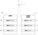
- the figure which shows the schematic structure of an automatic traveling system, and the installation state of a reference station apparatus Block diagram showing communication control states of a reference station and a mobile station in an automatic driving system
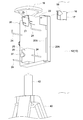
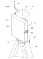
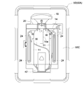
- the figure which shows the appearance state of the reference station equipment The figure which shows the structure of the antenna support part for communication
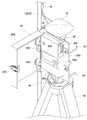
- the figure which shows the state of the back side of the reference station main body in a reference station apparatus The figure which shows the state of the front side of the reference station main body in a reference station apparatus
- the figure explaining the storing procedure to the storage box of a reference station apparatus The figure which shows the structure of the storage frame which accommodates a support rod and a support leg.
- the reference station device 10 of the present embodiment is used as a reference station in an automatic traveling system for automatically traveling a work vehicle 1 as a mobile station along a predetermined route. It is configured.
- a tractor is illustrated as the work vehicle 1.
- a walk-type work vehicle such as a rice transplanter, a combiner, a civil engineering / architecture work device, a snowplow, etc. Applicable.
- a positioning antenna 2 that receives a positioning signal from a positioning satellite 7 constituting a satellite positioning system (NSS: Navigation Satellite System) is installed on, for example, the upper surface of a roof of a cabin of a work vehicle 1 that travels on a work site.
- NSS Navigation Satellite System
- the work vehicle 1 is a mobile station.
- a reference station apparatus 10 having a positioning antenna 19 that receives a positioning signal from the same positioning satellite 7 as that of the work vehicle 1 is installed in the vicinity of a work place where the work vehicle 1 automatically travels. 10 is the reference station.
- the automatic traveling system is configured to measure the current position of the work vehicle 1 using positioning signals received by the reference station device 10 and the work vehicle 1.
- the work vehicle 1 is provided with a control unit 4 configured by a CPU, a storage device, and the like, and a communication antenna 3 that performs wireless communication between the communication antenna 11 of the reference station device 10. It has been.
- the reference station device 10 is provided with a control unit 30 configured by a CPU, a storage device, and the like, and a communication antenna 11 that performs wireless communication with the communication antenna 3 of the work vehicle 1.
- Each of these communication antennas 3 and 11 is configured to be able to perform wireless communication through WiFi or the like with the portable information terminal 5 (see FIG. 1) such as a tablet personal computer used by the user.
- the frequency band used for each wireless communication may be a common frequency band or different frequency bands.
- the portable information terminal 5 is comprised from the tablet-type personal computer etc. which have a touch panel, for example, can display various information on a touch panel, and various information can also be input by operating a touch panel. .
- the portable information terminal 5 can be used by being carried outside the work vehicle 1 by the user, and can also be used by being mounted on the side of the driver's seat of the work vehicle 1 or the like.
- the communication antennas 3 and 11 enable real-time information transmission / reception between the work vehicle 1 and the reference station device 10. Furthermore, it is possible to remotely operate the work vehicle 1 using the portable information terminal 5 that has executed predetermined application software.
- the control unit 4 provided in the work vehicle 1 executes predetermined computer software to execute a mobile station positioning process, an azimuth specifying process, an automatic traveling control, and the like described below.
- the mobile station positioning process executed by the control unit 4 on the work vehicle 1 side is configured as a process for obtaining mobile station positioning information indicating the latitude and longitude of the current position of the work vehicle 1 which is a mobile station.
- this mobile station positioning process positioning based on the positioning signal received from the positioning satellite 7 by the positioning antenna 2 installed in the work vehicle 1 and the correction information received from the reference station device 10 is executed, and the mobile station positioning information is obtained. Is required.
- various positioning methods such as a differential positioning method (DGPS positioning method) and a real-time kinematic positioning method (RTK-GPS positioning method) are applied as positioning performed by mobile station positioning processing.
- the control unit 4 repeatedly performs positioning by mobile station positioning processing, for example, every few seconds, and sequentially stores mobile station positioning information obtained by the positioning in association with time information at the time of positioning.
- the azimuth angle specifying process executed by the control unit 4 on the work vehicle 1 side is configured as a process for obtaining the azimuth angle of the work vehicle 1.
- the azimuth of the work vehicle 1 is obtained from the change state of the mobile station positioning information obtained by the positioning in the mobile station positioning process as the work vehicle 1 moves.
- the mobile station positioning information that has already been saved is referred to when the current mobile station positioning information is obtained by the mobile station positioning process. Then, the direction of the velocity vector from the immediately preceding mobile station positioning information toward the current mobile station positioning information can be specified as the azimuth angle of the work vehicle 1.
- the mobile station positioning information immediately before the mobile station positioning information obtained by the positioning in the mobile station positioning process stored immediately before can be used. For example, at the start of traveling of the work vehicle 1, Independent positioning or mobile station positioning information obtained by user input can also be used.
- the control unit 4 sequentially identifies the azimuth angle of the work vehicle 1 each time positioning is performed by, for example, mobile station positioning processing, and associates the obtained azimuth angle of the work vehicle 1 with time information at the time of identification. Save sequentially.
- the automatic travel control executed by the control unit 4 on the work vehicle 1 side is configured as a process for executing the automatic travel of the work vehicle 1.
- automatic travel of the work vehicle 1 along a predetermined target travel route is executed using mobile station positioning information obtained by positioning in the mobile station positioning process.
- the portable information terminal 5 information such as a target travel route necessary for automatic traveling of the work vehicle 1 is generated by the user, and the information is transmitted to the work vehicle 1 side and stored.
- measurement is performed by an IMU (Internal Measurement Unit) having an azimuth angle of the work vehicle 1 specified by the azimuth angle specifying process, a three-axis gyro, a three-direction accelerometer, and the like.
- IMU Internal Measurement Unit
- Various devices such as an engine control device, a transmission device, and a steering device equipped in the work vehicle 1 are automatically controlled while referring to the posture and the like of the work vehicle 1 in a timely manner.
- the work vehicle is arranged so that the current position of the work vehicle 1 indicated by the mobile station positioning information obtained by the positioning in the mobile station positioning process is along the target travel route received from the portable information terminal 5. 1 automatic traveling is executed.
- the control unit 30 provided in the reference station device 10 executes predetermined computer software to execute a reference station positioning process, a reference station registration process, a correction information generation process, and the like described below.
- the reference station positioning process executed by the control unit 30 on the reference station apparatus 10 side is configured as a process for obtaining reference station positioning information indicating the latitude and longitude of the current position of the reference station apparatus 10 that is the reference station.
- this reference station positioning process positioning based on the positioning signal received from the positioning satellite 7 is executed by the positioning antenna 19 installed in the reference station apparatus 10 to obtain reference station positioning information.
- a positioning signal is analyzed from a plurality of positioning satellites 7 received by a single positioning antenna 19, and the positioning signal of the positioning antenna 19 is determined from the propagation time of each positioning signal.
- the distance from each positioning satellite 7 is determined.
- reference station positioning information indicating the current position of the reference station apparatus 10 provided with the positioning antenna 19 can be obtained.
- a positioning signal is analyzed from a plurality of positioning satellites 7 received by one positioning antenna 19, and each of the positioning antennas 19 is determined from the propagation time of each positioning signal.
- a single positioning method for obtaining the distance from the positioning satellite 7 is applied.
- the reference station registration process executed by the control unit 30 on the reference station apparatus 10 side is configured to register reference station installation position information indicating the latitude and longitude of the installation position of the reference station apparatus 10 installed at a fixed position. For example, when the reference station apparatus 10 is newly installed or the installation position of the reference station apparatus 10 is changed, registration of the reference station installation information is executed by the reference station registration process. Further, the reference station registration process is an automatic registration in which the reference station device 10 side determines the installation position of the reference station device 10 and automatically registers it in order to reliably register accurate reference station installation position information while omitting manual input work. The process is configured to be executable.
- the correction information generation process executed by the control unit 30 on the reference station device 10 side is configured as a process for generating correction information for the positioning signal received from the positioning satellite 7.
- the positioning satellite 7 is based on the positioning signal received from the positioning satellite 7 by the positioning antenna 19 installed in the reference station apparatus 10 and the reference station installation position information registered in advance in the reference station registration process. Correction information for the positioning signal received from is generated.
- the control unit 30 on the reference station device 10 side generates correction information by correction information generation processing, for example, repeatedly every few seconds, and sends the generated correction information to the work vehicle 1 side in real time through the communication antennas 3 and 11. Send.
- the control unit 4 on the work vehicle 1 side uses the correction information received from the reference station apparatus 10 side for positioning in the differential positioning method or the real-time kinematic positioning method in the mobile station positioning process.
- the difference data is the position of the reference station apparatus 10 indicated by the reference station positioning information obtained by positioning in the reference station positioning process with respect to the installation position of the reference station apparatus 10 indicated by the reference station installation position information registered in advance in the reference station registration process. It is data about the difference.
- the current position of the work vehicle 1 is obtained by executing independent positioning, and the current position obtained by the independent positioning is used as the reference station device 10. It corrects with the difference data received from the side. By this correction, mobile station positioning information indicating the latitude, longitude, etc. of the accurate current position of the work vehicle 1 is obtained.
- the reference station installation position information and the phase data are obtained in the correction information generation process of the reference station apparatus 10 from which correction information is acquired. Are generated as correction information and transmitted to the work vehicle 1 side.
- the reference station installation position information is information regarding the reference station installation position registered in advance in the reference station registration process.
- the phase data is data relating to the phase of the positioning signal received by the positioning antenna 19 on the reference station device 10 side.
- the phase data of the positioning signal received by the positioning antenna 2 on the work vehicle 1 side and the positioning data on the reference station device 10 side are used.
- the phase data of the positioning signal received by the antenna 19 is analyzed in real time.
- the relative positional relationship of the current position of the work vehicle 1 with respect to the installation position of the reference station device 10 is obtained, and the latitude / longitude of the current current position of the work vehicle 1 is obtained from the relative positional relationship and the reference station installation position information.
- the mobile station positioning information shown is obtained.
- the reference station apparatus 10 according to the present invention is used in an automatic travel system.
- the application of the reference station apparatus 10 is not limited to this.
- Various processing contents such as positioning processing performed in the automatic traveling system may be changed as appropriate.
- the reference station apparatus 10 includes a communication antenna 11, a positioning antenna 19, and a control unit 30.
- the communication antenna 11 performs wireless communication with the work vehicle 1 as a mobile station.
- the positioning antenna 19 receives a positioning signal from the positioning satellite 7.
- the control unit 30 controls the operation of the positioning antenna 19 and the communication antenna 11.
- the reference station apparatus 10 is provided with a reference station main body 20 supported by a support leg 40 composed of a tripod or the like standing on the ground surface.
- a control unit 30 and a positioning antenna 19 are attached to the reference station body 20. Since the positioning antenna 19 has a relatively heavy weight of about 2 kg, there is a problem that it is not stable when installed at a high place. Therefore, in the present embodiment, the positioning antenna 19 is directly attached to the reference station main body 20 together with the control unit 30, and is stably installed at a relatively low place of about 1 m on the center of gravity axis of the support leg 40. Will be. Therefore, highly accurate positioning is possible.
- the reference station main body 20 is configured by a substantially box-shaped housing that accommodates the control unit 30 therein and has an open / close door 20 ⁇ / b> A that can open and close the front side of the control unit 30. ing.
- the housing constituting the reference station main body 20 includes a base plate 20B supported by a support leg 40 and having a control unit 30 fixed to the front surface, and a box-shaped opening / closing door 20A disposed on the front surface side.
- the positioning antenna 19 is attached to a bracket 21 fixed to the rear upper end portion side of the base plate 20B with screws.
- the opening / closing door 20 ⁇ / b> A and the base plate 20 ⁇ / b> B are connected to each other via a hinge 20 ⁇ / b> C in which side edges are arranged vertically.
- the open / close door 20A is between an open state (see FIG. 8) that swings sideways with respect to the front surface of the base plate 20B and a closed state (see FIG. 7) that is close to the front surface of the base plate 20B.
- the posture can be changed and opened and closed freely. Therefore, when the open / close door 20A is opened, as shown in FIG.
- the operation on the operation unit 30a such as a key switch and a power switch provided on the front surface of the control unit 30 and the visual recognition on the display unit 30b such as a liquid crystal display are performed. Can be easily performed.
- the opening / closing door 20A is closed, the front surface of the control unit 30 is covered with the box-shaped opening / closing door 20A, and the control unit 30 is prevented from being erroneously operated. Deterioration due to sunlight, failure due to rain, dust, or the like can be suitably suppressed.
- a battery 30 c for power supply is attached to the side surface of the control unit 30. If the door 20A is opened, the battery 30c can be replaced.
- a connector 30d for connecting the wiring W to the positioning antenna 19, the communication antenna 11, and the like are provided on the bottom surface of the control unit 30. And since the bottom part of 20 A of opening / closing doors is open
- a wire winding portion 24 made of a rod-like body capable of winding the wiring W connected to the positioning antenna 19 and the communication antenna 11 is provided on the back surface of the base plate 20 ⁇ / b> B of the reference station main body 20 . Therefore, the wiring W removed from the positioning antenna 19 and the communication antenna 11 and the surplus wiring W during transportation can be wound around the wiring winding portion 24 so as not to get in the way.
- the reference station main body 20 is provided with a support leg attachment portion 25 that is detachably attached to the support leg 40.
- the support leg attachment portion 25 has a rectangular tube-shaped sleeve portion 26 fixed to the back side of the base plate 20B of the reference station main body 20.
- the reference station main body 20 is attached to the upper end portion of the support leg 40 in a state in which the sleeve portion 26 is externally fitted to the columnar main body attachment column portion 42 fixed to the upper end portion of the support leg 40. It is done.
- the sleeve portion 26 is provided with a fixing screw 27 for fixing the main body mounting column portion 42 inserted into the sleeve portion 26.
- the reference station main body 20 can be removed from the support leg 40 and transported. Further, in this embodiment, a tripod is used as the support leg 40, but another support leg such as a pile can be used instead of the tripod as long as the main body mounting column portion 42 is provided. .
- the reference station apparatus 10 is provided with a bar-like support bar 13 that extends vertically as a communication antenna support unit 12 that supports the communication antenna 11 above the reference station body 20. Yes.
- a bar-like support bar 13 that extends vertically as a communication antenna support unit 12 that supports the communication antenna 11 above the reference station body 20.
- a substantially T-shaped bracket 14 is attached to the upper end of the support bar 13.
- a relatively strong magnet is attached to the bottom of the communication antenna 11.
- a pair of communication antennas 11 are fixed to both ends of the upper surface of the bracket 14 attached to the upper end of the support bar 13 by magnetic adhesion.
- a sleeve portion 14 a is provided at the center of the lower surface of the bracket 14. The communication antenna 11 is detachably attached to the upper end portion of the support bar 13 in a state where the sleeve portion 14a is externally fitted to a columnar insertion portion 13a formed at the upper end portion of the support bar 13. become.
- the support bar 13 is configured by fitting three bar-like support bar members 13A, 13B, and 13C having a length of about 1 m in a fitting manner. Accordingly, the support bar 13 can be divided into the respective support bar members 13A, 13B, and 13C and conveyed in a compact state.
- the reference station device 10 has a communication antenna mounting portion 16 that detachably mounts a support bar 13 that constitutes the communication antenna support portion 12 to the reference station main body 20. Is provided.
- the communication antenna mounting portion 16 is configured to be able to hold the support bar 13 provided on the side of the reference station main body 20 with the lower end portion 13b of the support bar 13 in contact with the ground surface.
- the communication antenna mounting portion 16 includes a base plate 22, a pressing member 17, and fixing screws 18.
- the base plate 22 is fixed to a side edge portion of the base plate 20B of the reference station main body 20.
- the pressing member 17 is disposed to face the base plate 22.
- the fixing screw 18 is fastened in a state where the pressing member 17 is brought close to the base plate 22. And the lower end part 13b contact
- the support bar 13 is fixed in a state along the side surface portion of the reference station main body 20.
- a cylindrical space provided in the reference station main body 20 and extending in the vertical direction is formed between the base plate 22 and the presser member 17 fixed to the base plate 22 by the fixing screw 18. .
- the support bar 13 is inserted into the cylindrical space on the side of the reference station main body 20 in a standing posture so that the lower end 13b is placed on the ground surface at the side of the reference station main body 20. It will be held in a contact state. By holding the support bar 13 in this manner, the posture of the support bar 13 and the communication antenna 11 attached to the upper end thereof can be stabilized while supporting the communication antenna 11 at an appropriate height. .
- the support bar 13 can be easily detached from the reference station main body 20 and transported separately from the reference station main body 20.
- the reference station main body 20 to which the control unit 30 and the positioning antenna 19 are attached can be detached from the support leg 40. Further, the support rod 13 as the communication antenna support 12 to which the communication antenna 11 is attached can be removed from the reference station main body 20. In this state, the reference station main body 20 can be transported. Also, the communication antenna 11 can be transported in a state where it is detached from the support bar 13.
- the reference station main body 20, the communication antenna 11 and the bracket 14 to which the communication station main body 20 is fixed can be transported in a state of being stored in a predetermined storage box 50, as shown in FIGS.
- the storage box 50 includes a rectangular container-like box body 50A, a lid member 50B capable of sealing the upper surface opening, and a filler 50C for defining the interior of the box body 50A in a desired shape space.
- the reference station main body 20 is stored in a lying state in a space defined by the filler 50C inside the box main body 50A, and the bracket 14 and the communication antenna 11 fixed thereto are stored in a state overlapping the reference station main body 20. be able to.
- the communication antenna 11 is magnetically attached to both end portions of the surface of the bracket 14 where the sleeve portion 14a is projected.
- the necessary storage is required compared to the case where the communication antenna 11 is magnetically attached to both ends of the surface of the bracket 14 opposite to the surface on which the sleeve portion 14a protrudes. Space can be made compact.
- the support leg 40 from which the reference station main body 20 is removed and the support bar 13 for supporting the communication antenna 11 are attached to the step S provided in the work vehicle 1. It can be conveyed in a state of being stored in the storage frame 60 that has been stored.
- the storage frame 60 includes a support leg storage unit 61 that can store the support legs 40 in an upright position, and a support bar 13 divided into three support bar members 13A, 13B, and 13C. And a support bar member storage portion 62 that can be stored at the same time.
- the support leg storage unit 61 includes a fixed frame 61A fixed to the back side, an open / close frame 61B supported to be opened and closed on the front side of the fixed frame 61A, and a cylindrical tip provided on the lower side thereof. And a support portion 61C.
- the support bar member storage part 62 includes two support plate parts 62A and 62B that are spaced apart from each other in the vertical direction.
- the support plate parts 62A and 62B include the support bar members 13A and 13B, respectively.
- Three insertion holes 62a into which 13C is inserted in the vertical direction are formed.
- a tip support plate portion 62C with which the lower end portions of the support rod members 13A, 13B, 13C inserted into the insertion hole portion 62a abut is provided.
- the support bar members 13A, 13B, and 13C are moved to the upper and lower support plate parts 62A, It inserts from above into each insertion hole 62a of 62B.
- the lower end portions of the support rod members 13A, 13B, and 13C are brought into contact with the tip support plate portion 62C. In this state, the support bar members 13A, 13B, and 13C are stably held in an upright posture.
- the lower support plate portion 62B and the tip support plate portion 62C are integrally formed of a plate-like member having a U-shaped cross section.
- the storage frame 60 is fixed to step S of the work vehicle 1 as shown in FIG. That is, the step S is sandwiched between the bottom plate portion 63 provided with the tip support portion 61C of the support leg storage portion 61 on the upper surface and the clamping plate 64 that can be fixed to the lower surface side by the bolt 70 and the nut 71. It becomes a state. Therefore, the storage frame 60 can be easily attached to and detached from the step S.
- the reference station main body 20 is configured by a substantially box-shaped housing having the opening / closing door 20 ⁇ / b> A that can freely open and close the front side of the control unit 30.
- the configuration of the reference station body 20 can be modified as appropriate.
- the opening / closing door 20A may be omitted, and the front side of the control unit 30 may be opened.
- the support rod 13 as the communication antenna support 12 that supports the communication antenna 11 above the reference station main body 20 is placed against the reference station main body 20 with the lower end 13b touching the ground. It was configured to hold in contact.
- the lower end portion 13b of the support bar 13 may be floated without being brought into contact with the ground surface, or may be configured to be held by the support leg 40.
- the reference station main body 20 is configured to have the support leg attachment portion 25 that is detachably attached to the support leg 40 standing on the ground surface. 20 and the support leg 40 may be integrated so as not to be separated. In addition, when this configuration is adopted, if the support leg 40 is configured to be foldable, it can be made compact and easily transported.
- the present invention can be applied to a reference station device or the like used for an automatic driving system.
Abstract
Provided is a reference station device that is capable of high-accuracy positioning whilst maintaining stability, even when configured so as to be portable. This reference station device 10 comprises: communications antennas 11 that conduct wireless communications with a mobile station; a positioning antenna 19 that receives a positioning signal from a positioning satellite; and a control unit 30 that controls the operation of the positioning antenna 19 and the communications antennas 11. The device comprises: a reference station body 20 to which the control unit 30 and the positioning antenna 19 are mounted; a communications antenna support 12 which supports the communications antennas 11 above the reference station body 20; and a communications antenna mounting part 16 with which the communications antenna support 13 is detachably mounted to the reference station body 20.
Description
本発明は、移動局との間で無線通信を行う通信用アンテナと、測位衛星から測位信号を受信する測位用アンテナと、前記測位用アンテナ及び前記通信用アンテナの作動を制御する制御ユニットと、を備えた基準局装置に関する。
The present invention includes a communication antenna that performs wireless communication with a mobile station, a positioning antenna that receives a positioning signal from a positioning satellite, a control unit that controls the operation of the positioning antenna and the communication antenna, The present invention relates to a reference station apparatus provided with
近年、作業地での作業車両による農作業等を効率よく行うために、当該作業車両を自動走行させるための自動走行システムが開発されている(例えば、特許文献1を参照。)。このような自動走行システムでは、測位衛星からの測位信号を受信する測位用アンテナを、作業地を走行する移動局としての作業車両と、当該作業地近傍に設置された基準局としての基準局装置との双方に設置し、これら移動局と基準局の双方の測位用アンテナにて受信した測位信号を用いて、移動局である作業車両の現在位置を精度良く測位する。
また、このような自動走行システムで利用される基準局装置は、作業車両の走行領域に併せて適切な位置に設置することが望ましいため、可搬型として構成することが求められている。 2. Description of the Related Art In recent years, an automatic traveling system for automatically traveling a work vehicle has been developed in order to efficiently perform agricultural work or the like using a work vehicle at a work site (see, for example, Patent Document 1). In such an automatic traveling system, a positioning antenna that receives a positioning signal from a positioning satellite is provided between a work vehicle as a mobile station that travels on a work site and a reference station device as a reference station that is installed near the work site. The current position of the work vehicle, which is a mobile station, is measured with high accuracy using positioning signals that are installed on both sides and received by positioning antennas of both the mobile station and the reference station.
In addition, since the reference station device used in such an automatic traveling system is desirably installed at an appropriate position in accordance with the traveling region of the work vehicle, it is required to be configured as a portable type.
尚、携帯端末用の通信ネットワークの分野においては、簡易に設置可能な可搬型基地局装置(アクセスポイント)が提供されている(例えば、特許文献2を参照。)。しかしながら、この特許文献2の可搬型の基地局装置は、端末装置との通信を目的とするものであって、作業車両の自動走行システムに利用される基準局装置のように、測位衛星との通信を行うものではない。
In the field of communication networks for mobile terminals, portable base station devices (access points) that can be easily installed are provided (see, for example, Patent Document 2). However, the portable base station device disclosed in Patent Document 2 is intended for communication with a terminal device, and communicates with a positioning satellite like a reference station device used in an automatic traveling system for a work vehicle. Is not something to do.
自動走行システムに利用される基準局装置では、移動局となる作業車両との通信状態を良好なものとするために、移動局との間で無線通信を行う通信用アンテナについては、高い位置に設置することが好ましい。一方、測位用アンテナについては、比較的重量があるため、高い位置に設置した場合には、不安定となって転倒し易くなる上に、測位のずれが生じ易くなる。
In the reference station device used in the automatic driving system, in order to improve the communication state with the work vehicle serving as the mobile station, the communication antenna for performing wireless communication with the mobile station is installed at a high position. It is preferable to do. On the other hand, since the positioning antenna is relatively heavy, when it is installed at a high position, it becomes unstable and easily falls, and a positioning shift easily occurs.
この実情に鑑み、本発明の主たる課題は、可搬型に構成した場合でも安定姿勢を維持しつつ、高精度な測位が可能となる基準局装置を提供する点にある。
In view of this situation, a main problem of the present invention is to provide a reference station apparatus that can perform highly accurate positioning while maintaining a stable posture even when configured to be portable.
本発明の第1特徴構成は、移動局との間で無線通信を行う通信用アンテナと、
測位衛星から測位信号を受信する測位用アンテナと、
前記測位用アンテナ及び前記通信用アンテナの作動を制御する制御ユニットと、を備えた基準局装置であって、
前記制御ユニット及び前記測位用アンテナが取り付けられて地表面に支持される基準局本体と、
前記通信用アンテナを前記基準局本体よりも上方に支持する通信用アンテナ支持部と、
前記基準局本体に対して前記通信用アンテナ支持部を着脱自在に取り付ける通信用アンテナ取付部と、を備えた点にある。 A first characteristic configuration of the present invention includes a communication antenna for performing wireless communication with a mobile station,
A positioning antenna for receiving positioning signals from positioning satellites;
A control unit that controls the operation of the positioning antenna and the communication antenna, and a reference station device comprising:
A reference station body to which the control unit and the positioning antenna are attached and supported on the ground surface;
A communication antenna support for supporting the communication antenna above the reference station body;
And a communication antenna mounting portion for detachably mounting the communication antenna support portion to the reference station main body.
本構成によれば、測位衛星から測位信号を受信する測位用アンテナについては、制御ユニットと共に、地表面に安定して支持される基準局本体に直接取り付けられている。よって、測位用アンテナの安定化を図り、高精度な測位を実現することができる。一方、移動局との間で無線通信を行う通信用アンテナについては、基準局本体に対して取り付けられる通信用アンテナ支持部により支持されている。よって、基準局本体を低い位置に配置しながらも、通信用アンテナを基準局本体よりも上方のできるだけ高い位置に配置して、移動局側との間で良好な通信を実現することができる。
更に、通信用アンテナ取付部により、通信用アンテナを支持するための通信用アンテナ支持部を基準局本体から取り外して、コンパクトな状態で容易に搬送することができる。
従って、本発明により、可搬型に構成した場合でも安定姿勢を維持しつつ、高精度な測位が可能となる基準局装置を提供することができる。 According to this configuration, the positioning antenna that receives the positioning signal from the positioning satellite is directly attached to the reference station body that is stably supported on the ground surface together with the control unit. Therefore, the positioning antenna can be stabilized and highly accurate positioning can be realized. On the other hand, a communication antenna that performs wireless communication with a mobile station is supported by a communication antenna support that is attached to the reference station body. Therefore, it is possible to achieve good communication with the mobile station side by disposing the communication antenna at a position as high as possible above the reference station body while disposing the reference station body at a low position.
Further, the communication antenna mounting portion for supporting the communication antenna can be removed from the reference station main body by the communication antenna mounting portion and can be easily transported in a compact state.
Therefore, according to the present invention, it is possible to provide a reference station apparatus capable of performing highly accurate positioning while maintaining a stable posture even when configured to be portable.
本発明の第2特徴構成は、前記基準局本体が、前記制御ユニットを内部に収容すると共に、当該制御ユニットの前面側を開閉自在な開閉扉を有する点にある。
The second characteristic configuration of the present invention is that the reference station main body accommodates the control unit therein and has an open / close door that can be opened and closed on the front side of the control unit.
本構成によれば、基準局本体に制御ユニットを収容した状態において、当該制御ユニットの前面側を開閉扉により開閉することができる。よって、開閉扉を開状態とすれば、制御ユニットの前面側の操作部に対する操作等を容易に行うことができ、一方、開閉扉を閉状態とすれば、誤操作を防止しつつ、当該制御ユニットの太陽光による劣化や雨や埃等による故障等を好適に抑制することができる。
According to this configuration, the front side of the control unit can be opened and closed by the opening / closing door in a state where the control unit is accommodated in the reference station body. Therefore, if the open / close door is in the open state, the operation of the control unit on the front side of the control unit can be easily performed. On the other hand, if the open / close door is in the closed state, the control unit is prevented from being erroneously operated. It is possible to suitably suppress deterioration due to sunlight, failure due to rain or dust, and the like.
本発明の第3特徴構成は、前記通信用アンテナ支持部が、上下に延びる支持棒で構成されていると共に、当該支持棒の上端部に、前記通信用アンテナが着脱自在に取り付けられ、
前記通信用アンテナ取付部が、前記基準局本体の側方に設けられた前記支持棒を当該支持棒の下端部を地表面に当接させた状態で保持可能に構成されている点にある。 According to a third characteristic configuration of the present invention, the communication antenna support portion is configured by a support rod extending vertically, and the communication antenna is detachably attached to an upper end portion of the support rod.
The communication antenna mounting portion is configured to be able to hold the support rod provided on the side of the reference station main body in a state where the lower end portion of the support rod is in contact with the ground surface.
本構成によれば、通信用アンテナ取付部により、上端部に通信用アンテナが取り付けられた支持棒を、下端部を地表面に当接させた状態で基準局本体の側方に設けて保持することができる。よって、通信用アンテナを適切な高さに支持しながら、支持棒の下端部が地表面に当接することにより、支持棒及びその上端部に取り付けられた通信用アンテナの姿勢を安定化させることができる。更に、支持棒の下端部が地表面に当接するので、支持棒及び通信用アンテナの荷重を地表面で支持することができ、その荷重が基準局本体側にかかることを防止できる。よって、基準局本体及びそれに取り付けられる測位用アンテナの姿勢についても安定化させて、基準局本体の転倒を抑制しながら、測位用アンテナによる測位の精度を一層向上することができる。
According to this configuration, the support antenna having the communication antenna attached to the upper end is provided and held on the side of the reference station main body with the lower end in contact with the ground surface by the communication antenna attachment. Can do. Therefore, while supporting the communication antenna at an appropriate height, the posture of the support rod and the communication antenna attached to the upper end portion can be stabilized by the lower end portion of the support rod coming into contact with the ground surface. it can. Furthermore, since the lower end portion of the support bar is in contact with the ground surface, the load of the support bar and the communication antenna can be supported on the ground surface, and the load can be prevented from being applied to the reference station body side. Therefore, it is possible to stabilize the posture of the reference station main body and the positioning antenna attached thereto, and to further improve the accuracy of positioning by the positioning antenna while suppressing the overturn of the reference station main body.
本発明の第4特徴構成は、前記基準局本体が、地表面に立設される支持脚体に対して着脱自在に取り付けられる支持脚体取付部を有する点にある。
A fourth characteristic configuration of the present invention is that the reference station main body has a support leg attachment portion that is detachably attached to a support leg standing on the ground surface.
本構成によれば、支持脚体取付部により、基準局本体を地表面に立設される支持脚体から取り外して、一層容易に搬送することができる。更に、基準局本体が支持脚体取付部を有することで、三脚や杭など複数種の支持脚体に対して適宜基準局本体を取り付けることができる。
According to this configuration, the reference leg body can be detached from the support leg standing on the ground surface by the support leg attachment portion, and can be transported more easily. Furthermore, since the reference station main body has the support leg attachment portion, the reference station main body can be appropriately attached to a plurality of types of support legs such as a tripod and a pile.
本発明に係る基準局装置の実施形態について図面に基づいて説明する。
図1及び図2に示すように、本実施形態の基準局装置10は、移動局としての作業車両1を予め定められた経路に沿って自動走行させるための自動走行システムにおいて基準局として利用されものとして構成されている。
尚、本実施形態では、作業車両1としてトラクタを例示しているが、トラクタの他、田植機、コンバイン、土木・建築作業装置、除雪車等、乗用型作業車両に加え、歩行型作業車両も適用可能である。 An embodiment of a reference station apparatus according to the present invention will be described with reference to the drawings.
As shown in FIGS. 1 and 2, thereference station device 10 of the present embodiment is used as a reference station in an automatic traveling system for automatically traveling a work vehicle 1 as a mobile station along a predetermined route. It is configured.
In this embodiment, a tractor is illustrated as thework vehicle 1. However, in addition to a tractor, a walk-type work vehicle such as a rice transplanter, a combiner, a civil engineering / architecture work device, a snowplow, etc. Applicable.
図1及び図2に示すように、本実施形態の基準局装置10は、移動局としての作業車両1を予め定められた経路に沿って自動走行させるための自動走行システムにおいて基準局として利用されものとして構成されている。
尚、本実施形態では、作業車両1としてトラクタを例示しているが、トラクタの他、田植機、コンバイン、土木・建築作業装置、除雪車等、乗用型作業車両に加え、歩行型作業車両も適用可能である。 An embodiment of a reference station apparatus according to the present invention will be described with reference to the drawings.
As shown in FIGS. 1 and 2, the
In this embodiment, a tractor is illustrated as the
(自動走行システム)
先ず、本実施形態の基準局装置10を利用した自動走行システムの構成について説明する。
自動走行システムでは、作業地を走行する作業車両1の例えばキャビンのルーフ上面に、衛星測位システム(NSS:Navigation Satellite System)を構成する測位衛星7からの測位信号を受信する測位用アンテナ2を設置して、当該作業車両1を移動局としている。一方、作業車両1の自動走行を行う作業地の近傍には、作業車両1側と同じ測位衛星7からの測位信号を受信する測位用アンテナ19を有する基準局装置10を設置して、当該基準局装置10を基準局としている。
自動走行システムは、これら基準局装置10と作業車両1との夫々にて受信した測位信号を用いて、作業車両1の現在位置を測位するものとして構成されている。 (Automatic driving system)
First, the configuration of an automatic traveling system using thereference station apparatus 10 of the present embodiment will be described.
In the automatic traveling system, apositioning antenna 2 that receives a positioning signal from a positioning satellite 7 constituting a satellite positioning system (NSS: Navigation Satellite System) is installed on, for example, the upper surface of a roof of a cabin of a work vehicle 1 that travels on a work site. Thus, the work vehicle 1 is a mobile station. On the other hand, a reference station apparatus 10 having a positioning antenna 19 that receives a positioning signal from the same positioning satellite 7 as that of the work vehicle 1 is installed in the vicinity of a work place where the work vehicle 1 automatically travels. 10 is the reference station.
The automatic traveling system is configured to measure the current position of thework vehicle 1 using positioning signals received by the reference station device 10 and the work vehicle 1.
先ず、本実施形態の基準局装置10を利用した自動走行システムの構成について説明する。
自動走行システムでは、作業地を走行する作業車両1の例えばキャビンのルーフ上面に、衛星測位システム(NSS:Navigation Satellite System)を構成する測位衛星7からの測位信号を受信する測位用アンテナ2を設置して、当該作業車両1を移動局としている。一方、作業車両1の自動走行を行う作業地の近傍には、作業車両1側と同じ測位衛星7からの測位信号を受信する測位用アンテナ19を有する基準局装置10を設置して、当該基準局装置10を基準局としている。
自動走行システムは、これら基準局装置10と作業車両1との夫々にて受信した測位信号を用いて、作業車両1の現在位置を測位するものとして構成されている。 (Automatic driving system)
First, the configuration of an automatic traveling system using the
In the automatic traveling system, a
The automatic traveling system is configured to measure the current position of the
図2に示すように、作業車両1には、CPUや記憶装置等で構成された制御ユニット4と、基準局装置10の通信用アンテナ11との間で無線通信を行う通信用アンテナ3とが設けられている。一方、基準局装置10には、CPUや記憶装置等で構成された制御ユニット30と、作業車両1の通信用アンテナ3との間で無線通信を行う通信用アンテナ11とが設けられている。これら通信用アンテナ3,11の夫々は、ユーザが利用するタブレット型パーソナルコンピュータ等の携帯情報端末5(図1参照)との間でも、WiFi等を通じた無線通信が可能に構成されている。
As shown in FIG. 2, the work vehicle 1 is provided with a control unit 4 configured by a CPU, a storage device, and the like, and a communication antenna 3 that performs wireless communication between the communication antenna 11 of the reference station device 10. It has been. On the other hand, the reference station device 10 is provided with a control unit 30 configured by a CPU, a storage device, and the like, and a communication antenna 11 that performs wireless communication with the communication antenna 3 of the work vehicle 1. Each of these communication antennas 3 and 11 is configured to be able to perform wireless communication through WiFi or the like with the portable information terminal 5 (see FIG. 1) such as a tablet personal computer used by the user.
各無線通信に用いられる周波数帯域は、共通の周波数帯域であってもよいし、互いに異なる周波数帯域であってもよい。また、携帯情報端末5は、例えば、タッチパネルを有するタブレット型のパーソナルコンピュータ等から構成され、各種情報をタッチパネルに表示可能であり、タッチパネルを操作することで、各種の情報も入力可能となっている。携帯情報端末5は、ユーザが作業車両1の外部にて携帯して使用することが可能であると共に、作業車両1の運転席の側脇等に装着して使用することもできる。
The frequency band used for each wireless communication may be a common frequency band or different frequency bands. Moreover, the portable information terminal 5 is comprised from the tablet-type personal computer etc. which have a touch panel, for example, can display various information on a touch panel, and various information can also be input by operating a touch panel. . The portable information terminal 5 can be used by being carried outside the work vehicle 1 by the user, and can also be used by being mounted on the side of the driver's seat of the work vehicle 1 or the like.
通信用アンテナ3,11により、作業車両1と基準局装置10との間でリアルタイムの情報の送受信が可能となる。更には、所定のアプリケーションソフトウェアを実行した携帯情報端末5を用いて、作業車両1を遠隔で操作することが可能となる。
The communication antennas 3 and 11 enable real-time information transmission / reception between the work vehicle 1 and the reference station device 10. Furthermore, it is possible to remotely operate the work vehicle 1 using the portable information terminal 5 that has executed predetermined application software.
作業車両1に設けられた制御ユニット4は、所定のコンピュータソフトウェアを実行することで、以下に説明する移動局測位処理、方位角特定処理、及び、自動走行制御等を実行する。
The control unit 4 provided in the work vehicle 1 executes predetermined computer software to execute a mobile station positioning process, an azimuth specifying process, an automatic traveling control, and the like described below.
作業車両1側の制御ユニット4が実行する移動局測位処理は、移動局である作業車両1の現在位置の緯度・経度等を示す移動局測位情報を求める処理として構成されている。この移動局測位処理では、作業車両1に設置された測位用アンテナ2にて測位衛星7から受信した測位信号と基準局装置10から受信した補正情報とに基づく測位が実行されて、移動局測位情報が求められる。
The mobile station positioning process executed by the control unit 4 on the work vehicle 1 side is configured as a process for obtaining mobile station positioning information indicating the latitude and longitude of the current position of the work vehicle 1 which is a mobile station. In this mobile station positioning process, positioning based on the positioning signal received from the positioning satellite 7 by the positioning antenna 2 installed in the work vehicle 1 and the correction information received from the reference station device 10 is executed, and the mobile station positioning information is obtained. Is required.
例えば、移動局測位処理により行われる測位としては、ディファレンシャル測位方式(DGPS測位方式)、リアルタイムキネマティック測位方式(RTK-GPS測位方式)等の各種の測位方法が適用される。
制御ユニット4は、例えば数秒毎に移動局測位処理による測位を繰り返し実行し、その測位により得られた移動局測位情報を、測位時の時間情報と関連付けて逐次保存する。 For example, various positioning methods such as a differential positioning method (DGPS positioning method) and a real-time kinematic positioning method (RTK-GPS positioning method) are applied as positioning performed by mobile station positioning processing.
The control unit 4 repeatedly performs positioning by mobile station positioning processing, for example, every few seconds, and sequentially stores mobile station positioning information obtained by the positioning in association with time information at the time of positioning.
作業車両1側の制御ユニット4が実行する方位角特定処理は、作業車両1の方位角を求める処理として構成されている。この方位角特定処理では、作業車両1の移動に伴って移動局測位処理での測位により得られた移動局測位情報の変化状態から、作業車両1の方位角が求められる。
The azimuth angle specifying process executed by the control unit 4 on the work vehicle 1 side is configured as a process for obtaining the azimuth angle of the work vehicle 1. In this azimuth specifying process, the azimuth of the work vehicle 1 is obtained from the change state of the mobile station positioning information obtained by the positioning in the mobile station positioning process as the work vehicle 1 moves.
例えば、方位角特定処理では、移動局測位処理により現在の移動局測位情報が得られた時点で、既に保存された直前の移動局測位情報を参照する。そして、その直前の移動局測位情報から現在の移動局測位情報に向かう速度ベクトルの向きを、作業車両1の方位角として特定することができる。
尚、上記直前の移動局測位情報としては、保存された直前の移動局測位処理での測位により得られた移動局測位情報を用いることができるが、例えば作業車両1の走行開始時においては、単独測位又はユーザが入力して得られた移動局測位情報を用いることもできる。 For example, in the azimuth angle specifying process, the mobile station positioning information that has already been saved is referred to when the current mobile station positioning information is obtained by the mobile station positioning process. Then, the direction of the velocity vector from the immediately preceding mobile station positioning information toward the current mobile station positioning information can be specified as the azimuth angle of thework vehicle 1.
In addition, as the mobile station positioning information immediately before, the mobile station positioning information obtained by the positioning in the mobile station positioning process stored immediately before can be used. For example, at the start of traveling of thework vehicle 1, Independent positioning or mobile station positioning information obtained by user input can also be used.
尚、上記直前の移動局測位情報としては、保存された直前の移動局測位処理での測位により得られた移動局測位情報を用いることができるが、例えば作業車両1の走行開始時においては、単独測位又はユーザが入力して得られた移動局測位情報を用いることもできる。 For example, in the azimuth angle specifying process, the mobile station positioning information that has already been saved is referred to when the current mobile station positioning information is obtained by the mobile station positioning process. Then, the direction of the velocity vector from the immediately preceding mobile station positioning information toward the current mobile station positioning information can be specified as the azimuth angle of the
In addition, as the mobile station positioning information immediately before, the mobile station positioning information obtained by the positioning in the mobile station positioning process stored immediately before can be used. For example, at the start of traveling of the
制御ユニット4は、例えば移動局測位処理による測位が実行される毎に作業車両1の方位角を逐次特定し、それにより得られた作業車両1の方位角を、特定時の時間情報と関連付けて逐次保存する。
The control unit 4 sequentially identifies the azimuth angle of the work vehicle 1 each time positioning is performed by, for example, mobile station positioning processing, and associates the obtained azimuth angle of the work vehicle 1 with time information at the time of identification. Save sequentially.
作業車両1側の制御ユニット4が実行する自動走行制御は、作業車両1の自動走行を実行する処理として構成されている。この自動走行制御では、移動局測位処理での測位により得られた移動局測位情報を用いて、予め定められた目標走行経路に沿った作業車両1の自動走行が実行される。
The automatic travel control executed by the control unit 4 on the work vehicle 1 side is configured as a process for executing the automatic travel of the work vehicle 1. In this automatic travel control, automatic travel of the work vehicle 1 along a predetermined target travel route is executed using mobile station positioning information obtained by positioning in the mobile station positioning process.
例えば、携帯情報端末5において、作業車両1の自動走行に必要な目標走行経路などの情報がユーザにより生成され、その情報が、作業車両1側に送信されて保存される。そして、自動走行制御では、方位角特定処理で特定された作業車両1の方位角や、3軸のジャイロと3方向の加速度計等を有するIMU(Inertial Measurement Unit:慣性計測装置)で計測される作業車両1の姿勢等を適時参照しながら、作業車両1に装備されたエンジン制御装置、変速装置及び操舵装置等の各種装置を自動制御する。この自動制御により、移動局測位処理での測位により得られた移動局測位情報が示す作業車両1の現在位置が携帯情報端末5から受信した目標走行経路に沿ったものになるように、作業車両1の自動走行が実行される。
For example, in the portable information terminal 5, information such as a target travel route necessary for automatic traveling of the work vehicle 1 is generated by the user, and the information is transmitted to the work vehicle 1 side and stored. In the automatic traveling control, measurement is performed by an IMU (Internal Measurement Unit) having an azimuth angle of the work vehicle 1 specified by the azimuth angle specifying process, a three-axis gyro, a three-direction accelerometer, and the like. Various devices such as an engine control device, a transmission device, and a steering device equipped in the work vehicle 1 are automatically controlled while referring to the posture and the like of the work vehicle 1 in a timely manner. With this automatic control, the work vehicle is arranged so that the current position of the work vehicle 1 indicated by the mobile station positioning information obtained by the positioning in the mobile station positioning process is along the target travel route received from the portable information terminal 5. 1 automatic traveling is executed.
基準局装置10に設けられた制御ユニット30は、所定のコンピュータソフトウェアを実行することで、以下に説明する基準局測位処理、基準局登録処理、補正情報生成処理等を実行する。
The control unit 30 provided in the reference station device 10 executes predetermined computer software to execute a reference station positioning process, a reference station registration process, a correction information generation process, and the like described below.
基準局装置10側の制御ユニット30が実行する基準局測位処理は、基準局である基準局装置10の現在位置の緯度経度等を示す基準局測位情報を求める処理として構成されている。この基準局測位処理では、基準局装置10に設置された測位用アンテナ19にて測位衛星7から受信した測位信号に基づく測位が実行されて、基準局測位情報が求められる。
The reference station positioning process executed by the control unit 30 on the reference station apparatus 10 side is configured as a process for obtaining reference station positioning information indicating the latitude and longitude of the current position of the reference station apparatus 10 that is the reference station. In this reference station positioning process, positioning based on the positioning signal received from the positioning satellite 7 is executed by the positioning antenna 19 installed in the reference station apparatus 10 to obtain reference station positioning information.
具体的に、基準局測位処理により行われる測位では、1つの測位用アンテナ19で受信した複数の測位衛星7から測位信号を解析して、それら夫々の測位信号の伝搬時間から、測位用アンテナ19の夫々の測位衛星7からの距離が求められる。このようにして得られた夫々の測位衛星7からの距離を解析することにより、測位用アンテナ19が設けられた基準局装置10の現在位置を示す基準局測位情報を求めることができる。例えば、基準局測位処理により行われる測位としては、1つの測位用アンテナ19で受信した複数の測位衛星7から測位信号を解析して、それら夫々の測位信号の伝搬時間から測位用アンテナ19の夫々の測位衛星7からの距離を求める単独測位方法が適用される。
Specifically, in the positioning performed by the reference station positioning processing, a positioning signal is analyzed from a plurality of positioning satellites 7 received by a single positioning antenna 19, and the positioning signal of the positioning antenna 19 is determined from the propagation time of each positioning signal. The distance from each positioning satellite 7 is determined. By analyzing the distances from the respective positioning satellites 7 thus obtained, reference station positioning information indicating the current position of the reference station apparatus 10 provided with the positioning antenna 19 can be obtained. For example, as positioning performed by the reference station positioning processing, a positioning signal is analyzed from a plurality of positioning satellites 7 received by one positioning antenna 19, and each of the positioning antennas 19 is determined from the propagation time of each positioning signal. A single positioning method for obtaining the distance from the positioning satellite 7 is applied.
基準局装置10側の制御ユニット30が実行する基準局登録処理は、固定位置に設置された基準局装置10の設置位置の緯度・経度等を示す基準局設置位置情報を登録するものとして構成されている。例えば、新規に基準局装置10を設置したり、基準局装置10の設置位置を変更した場合において、基準局登録処理により基準局設置情報の登録が実行される。
更に、基準局登録処理は、手動入力作業を省略しながら、正確な基準局設置位置情報を確実に登録するために、基準局装置10側で基準局装置10の設置位置を求めて自動的に登録する自動登録処理を実行可能に構成されている。 The reference station registration process executed by thecontrol unit 30 on the reference station apparatus 10 side is configured to register reference station installation position information indicating the latitude and longitude of the installation position of the reference station apparatus 10 installed at a fixed position. For example, when the reference station apparatus 10 is newly installed or the installation position of the reference station apparatus 10 is changed, registration of the reference station installation information is executed by the reference station registration process.
Further, the reference station registration process is an automatic registration in which thereference station device 10 side determines the installation position of the reference station device 10 and automatically registers it in order to reliably register accurate reference station installation position information while omitting manual input work. The process is configured to be executable.
更に、基準局登録処理は、手動入力作業を省略しながら、正確な基準局設置位置情報を確実に登録するために、基準局装置10側で基準局装置10の設置位置を求めて自動的に登録する自動登録処理を実行可能に構成されている。 The reference station registration process executed by the
Further, the reference station registration process is an automatic registration in which the
基準局装置10側の制御ユニット30が実行する補正情報生成処理は、測位衛星7から受信される測位信号に対する補正情報を生成する処理として構成されている。この補正情報生成処理では、基準局装置10に設置された測位用アンテナ19にて測位衛星7から受信した測位信号と、基準局登録処理で予め登録された基準局設置位置情報とに基づいて、測位衛星7から受信される測位信号に対する補正情報が生成される。
The correction information generation process executed by the control unit 30 on the reference station device 10 side is configured as a process for generating correction information for the positioning signal received from the positioning satellite 7. In this correction information generation process, the positioning satellite 7 is based on the positioning signal received from the positioning satellite 7 by the positioning antenna 19 installed in the reference station apparatus 10 and the reference station installation position information registered in advance in the reference station registration process. Correction information for the positioning signal received from is generated.
また、基準局装置10側の制御ユニット30は、例えば数秒毎に繰り返して補正情報生成処理により補正情報を生成し、その生成した補正情報を、通信用アンテナ3,11を通じてリアルタイムに作業車両1側に送信する。そして、作業車両1側の制御ユニット4では、基準局装置10側から受信した補正情報を、移動局測位処理におけるディファレンシャル測位方式又はリアルタイムキネマティック測位方式での測位に利用する。
The control unit 30 on the reference station device 10 side generates correction information by correction information generation processing, for example, repeatedly every few seconds, and sends the generated correction information to the work vehicle 1 side in real time through the communication antennas 3 and 11. Send. The control unit 4 on the work vehicle 1 side uses the correction information received from the reference station apparatus 10 side for positioning in the differential positioning method or the real-time kinematic positioning method in the mobile station positioning process.
例えば、作業車両1側の移動局測位処理において、ディファレンシャル測位方式で測位を行う場合には、補正情報の取得対象となる基準局装置10の補正情報生成処理では、基準局装置10の設置位置の差分データを補正情報として生成して作業車両1側に送信する。上記差分データは、基準局登録処理で予め登録された基準局設置位置情報が示す基準局装置10の設置位置に対し、基準局測位処理での測位により得られた基準局測位情報が示す基準局装置10の設置位置の差分に関するデータである。
For example, in the mobile station positioning process on the work vehicle 1 side, when positioning is performed by the differential positioning method, the correction data generation process of the reference station apparatus 10 that is the acquisition target of the correction information, the difference data of the installation position of the reference station apparatus 10 Is generated as correction information and transmitted to the work vehicle 1 side. The difference data is the position of the reference station apparatus 10 indicated by the reference station positioning information obtained by positioning in the reference station positioning process with respect to the installation position of the reference station apparatus 10 indicated by the reference station installation position information registered in advance in the reference station registration process. It is data about the difference.
そして、作業車両1側の移動局測位処理において、ディファレンシャル測位方式で測位を行うにあたり、単独測位を実行して作業車両1の現在位置を求め、その単独測位により得られた現在位置を基準局装置10側から受信した差分データにより補正する。この補正により、作業車両1の正確な現在位置の緯度・経度等を示す移動局測位情報を求める。
In the mobile station positioning process on the work vehicle 1 side, when performing positioning by the differential positioning method, the current position of the work vehicle 1 is obtained by executing independent positioning, and the current position obtained by the independent positioning is used as the reference station device 10. It corrects with the difference data received from the side. By this correction, mobile station positioning information indicating the latitude, longitude, etc. of the accurate current position of the work vehicle 1 is obtained.
また、作業車両1側の移動局測位処理において、リアルタイムキネマティック測位方式で測位を行う場合には、補正情報の取得対象となる基準局装置10の補正情報生成処理では、基準局設置位置情報と位相データとを補正情報として生成して作業車両1側に送信する。基準局設置位置情報は、基準局登録処理で予め登録された基準局設置位置に関する情報である。位相データは、基準局装置10側の測位用アンテナ19で受信した測位信号の位相に関するデータである。
In the mobile station positioning process on the work vehicle 1 side, when positioning is performed by the real-time kinematic positioning method, the reference station installation position information and the phase data are obtained in the correction information generation process of the reference station apparatus 10 from which correction information is acquired. Are generated as correction information and transmitted to the work vehicle 1 side. The reference station installation position information is information regarding the reference station installation position registered in advance in the reference station registration process. The phase data is data relating to the phase of the positioning signal received by the positioning antenna 19 on the reference station device 10 side.
そして、作業車両1側の移動局測位処理において、リアルタイムキネマティック測位方式で測位を行うにあたり、作業車両1側の測位用アンテナ2で受信した測位信号の位相データと、基準局装置10側の測位用アンテナ19で受信した測位信号の位相データとをリアルタイムで解析する。この解析により、基準局装置10の設置位置に対する作業車両1の現在位置の相対位置関係を求め、その相対位置関係と基準局設置位置情報とから、作業車両1の正確な現在位置の緯度・経度等を示す移動局測位情報を求める。
In the mobile station positioning process on the work vehicle 1 side, when performing positioning using the real-time kinematic positioning method, the phase data of the positioning signal received by the positioning antenna 2 on the work vehicle 1 side and the positioning data on the reference station device 10 side are used. The phase data of the positioning signal received by the antenna 19 is analyzed in real time. By this analysis, the relative positional relationship of the current position of the work vehicle 1 with respect to the installation position of the reference station device 10 is obtained, and the latitude / longitude of the current current position of the work vehicle 1 is obtained from the relative positional relationship and the reference station installation position information. The mobile station positioning information shown is obtained.
尚、本実施形態では、本発明に係る基準局装置10を自動走行システムに利用する例を説明したが、当該基準局装置10の用途は、これに限るものではない。また、自動走行システムにおいて実施される測位処理等の各種処理内容についても、適宜変更しても構わない。
In this embodiment, the example in which the reference station apparatus 10 according to the present invention is used in an automatic travel system has been described. However, the application of the reference station apparatus 10 is not limited to this. Various processing contents such as positioning processing performed in the automatic traveling system may be changed as appropriate.
(基準局装置)
次に、本実施形態の基準局装置10の構成について説明する。
図3に示すように、基準局装置10は、通信用アンテナ11と測位用アンテナ19と制御ユニット30とを備える。通信用アンテナ11は、移動局としての作業車両1との間で無線通信を行う。測位用アンテナ19は、測位衛星7から測位信号を受信する。制御ユニット30は、測位用アンテナ19及び通信用アンテナ11の作動を制御する。 (Base station equipment)
Next, the configuration of thereference station apparatus 10 of this embodiment will be described.
As shown in FIG. 3, thereference station apparatus 10 includes a communication antenna 11, a positioning antenna 19, and a control unit 30. The communication antenna 11 performs wireless communication with the work vehicle 1 as a mobile station. The positioning antenna 19 receives a positioning signal from the positioning satellite 7. The control unit 30 controls the operation of the positioning antenna 19 and the communication antenna 11.
次に、本実施形態の基準局装置10の構成について説明する。
図3に示すように、基準局装置10は、通信用アンテナ11と測位用アンテナ19と制御ユニット30とを備える。通信用アンテナ11は、移動局としての作業車両1との間で無線通信を行う。測位用アンテナ19は、測位衛星7から測位信号を受信する。制御ユニット30は、測位用アンテナ19及び通信用アンテナ11の作動を制御する。 (Base station equipment)
Next, the configuration of the
As shown in FIG. 3, the
基準局装置10には、図5~図8に示すように、地表面に立設される三脚等からなる支持脚体40により支持された基準局本体20が設けられている。この基準局本体20に制御ユニット30及び測位用アンテナ19が取り付けられている。
測位用アンテナ19については、約2Kgと比較的重量があるため、高所に設置すると安定しないという問題がある。そこで、本実施形態では、測位用アンテナ19は、制御ユニット30と共に基準局本体20に直接取り付けられて、支持脚体40の重心軸線上であって約1mと比較的低所に安定して設置されることになる。よって、高精度な測位が可能となる。 As shown in FIGS. 5 to 8, thereference station apparatus 10 is provided with a reference station main body 20 supported by a support leg 40 composed of a tripod or the like standing on the ground surface. A control unit 30 and a positioning antenna 19 are attached to the reference station body 20.
Since thepositioning antenna 19 has a relatively heavy weight of about 2 kg, there is a problem that it is not stable when installed at a high place. Therefore, in the present embodiment, the positioning antenna 19 is directly attached to the reference station main body 20 together with the control unit 30, and is stably installed at a relatively low place of about 1 m on the center of gravity axis of the support leg 40. Will be. Therefore, highly accurate positioning is possible.
測位用アンテナ19については、約2Kgと比較的重量があるため、高所に設置すると安定しないという問題がある。そこで、本実施形態では、測位用アンテナ19は、制御ユニット30と共に基準局本体20に直接取り付けられて、支持脚体40の重心軸線上であって約1mと比較的低所に安定して設置されることになる。よって、高精度な測位が可能となる。 As shown in FIGS. 5 to 8, the
Since the
基準局本体20は、図7及び図8に示すように、制御ユニット30を内部に収容すると共に、当該制御ユニット30の前面側を開閉自在な開閉扉20Aを有する略箱状の筐体で構成されている。基準局本体20を構成する筐体は、支持脚体40により支持されて前面に制御ユニット30が固定されるベースプレート20Bと、その前面側に配置された箱状の開閉扉20Aとを有して構成されている。測位用アンテナ19は、図5に示すように、ベースプレート20Bの背面上端部側に固定されたブラケット21に対してネジにより取り付けられている。
As shown in FIGS. 7 and 8, the reference station main body 20 is configured by a substantially box-shaped housing that accommodates the control unit 30 therein and has an open / close door 20 </ b> A that can open and close the front side of the control unit 30. ing. The housing constituting the reference station main body 20 includes a base plate 20B supported by a support leg 40 and having a control unit 30 fixed to the front surface, and a box-shaped opening / closing door 20A disposed on the front surface side. Has been. As shown in FIG. 5, the positioning antenna 19 is attached to a bracket 21 fixed to the rear upper end portion side of the base plate 20B with screws.
開閉扉20Aとベースプレート20Bとは、図8に示すように、側縁部同士が上下に配置された蝶番20Cを介して連結されている。そして、開閉扉20Aは、ベースプレート20Bの前面に対して側方に揺動して離間する開状態(図8参照)と、ベースプレート20Bの前面に近接する閉状態(図7参照)との間で、姿勢を変更して開閉自在となる。
よって、開閉扉20Aを開状態とすれば、図8に示すように、制御ユニット30の前面に設けられたキースイッチや電源スイッチなどの操作部30aに対する操作や液晶ディスプレイなどの表示部30bに対する視認を容易に行うことができる。一方、開閉扉20Aを閉状態とすれば、制御ユニット30の前面が箱状の開閉扉20Aにより覆われた状態となって、当該制御ユニット30への誤操作を防止しつつ、当該制御ユニット30の太陽光による劣化や雨や埃等による故障等を好適に抑制できる。 As shown in FIG. 8, the opening / closingdoor 20 </ b> A and the base plate 20 </ b> B are connected to each other via a hinge 20 </ b> C in which side edges are arranged vertically. The open / close door 20A is between an open state (see FIG. 8) that swings sideways with respect to the front surface of the base plate 20B and a closed state (see FIG. 7) that is close to the front surface of the base plate 20B. The posture can be changed and opened and closed freely.
Therefore, when the open /close door 20A is opened, as shown in FIG. 8, the operation on the operation unit 30a such as a key switch and a power switch provided on the front surface of the control unit 30 and the visual recognition on the display unit 30b such as a liquid crystal display are performed. Can be easily performed. On the other hand, when the opening / closing door 20A is closed, the front surface of the control unit 30 is covered with the box-shaped opening / closing door 20A, and the control unit 30 is prevented from being erroneously operated. Deterioration due to sunlight, failure due to rain, dust, or the like can be suitably suppressed.
よって、開閉扉20Aを開状態とすれば、図8に示すように、制御ユニット30の前面に設けられたキースイッチや電源スイッチなどの操作部30aに対する操作や液晶ディスプレイなどの表示部30bに対する視認を容易に行うことができる。一方、開閉扉20Aを閉状態とすれば、制御ユニット30の前面が箱状の開閉扉20Aにより覆われた状態となって、当該制御ユニット30への誤操作を防止しつつ、当該制御ユニット30の太陽光による劣化や雨や埃等による故障等を好適に抑制できる。 As shown in FIG. 8, the opening / closing
Therefore, when the open /
制御ユニット30の側面には、電源用のバッテリ30cが取り付けられている。開閉扉20Aを開状態とすれば、このバッテリ30cの交換が可能となる。
また、制御ユニット30の底面には、測位用アンテナ19や通信用アンテナ11等との間の配線Wを接続するためのコネクタ30d等が設けられている。そして、開閉扉20Aの底部が開放されていることから、開閉扉20Aの開閉操作において、このコネクタ30dに接続された配線Wが邪魔になることはない。
また、コネクタ30dの前方側には、閉状態とされた開閉扉20Aの下端部が存在し、コネクタ30dの後方側には、ベースプレート20Bの下端部が存在することになる。このことにより、基準局本体20が転倒した際でも、コネクタ30dから配線Wが外れ難くなる。 Abattery 30 c for power supply is attached to the side surface of the control unit 30. If the door 20A is opened, the battery 30c can be replaced.
On the bottom surface of thecontrol unit 30, a connector 30d for connecting the wiring W to the positioning antenna 19, the communication antenna 11, and the like are provided. And since the bottom part of 20 A of opening / closing doors is open | released, in the opening / closing operation of 20 A of opening / closing doors, the wiring W connected to this connector 30d does not become obstructive.
Further, the lower end portion of the open /close door 20A that is in the closed state exists on the front side of the connector 30d, and the lower end portion of the base plate 20B exists on the rear side of the connector 30d. As a result, even when the reference station body 20 falls, the wiring W is unlikely to come off from the connector 30d.
また、制御ユニット30の底面には、測位用アンテナ19や通信用アンテナ11等との間の配線Wを接続するためのコネクタ30d等が設けられている。そして、開閉扉20Aの底部が開放されていることから、開閉扉20Aの開閉操作において、このコネクタ30dに接続された配線Wが邪魔になることはない。
また、コネクタ30dの前方側には、閉状態とされた開閉扉20Aの下端部が存在し、コネクタ30dの後方側には、ベースプレート20Bの下端部が存在することになる。このことにより、基準局本体20が転倒した際でも、コネクタ30dから配線Wが外れ難くなる。 A
On the bottom surface of the
Further, the lower end portion of the open /
図6に示すように、基準局本体20のベースプレート20Bの背面には、測位用アンテナ19や通信用アンテナ11に接続される配線Wを巻き付け可能な棒状体からなる配線巻き付け部24が設けられている。よって、搬送時に測位用アンテナ19や通信用アンテナ11から取り外した配線Wや余剰の配線Wを邪魔にならないように配線巻き付け部24に巻き付けておくことができる。
As shown in FIG. 6, on the back surface of the base plate 20 </ b> B of the reference station main body 20, a wire winding portion 24 made of a rod-like body capable of winding the wiring W connected to the positioning antenna 19 and the communication antenna 11 is provided. . Therefore, the wiring W removed from the positioning antenna 19 and the communication antenna 11 and the surplus wiring W during transportation can be wound around the wiring winding portion 24 so as not to get in the way.
基準局本体20には、図5及び図6に示すように、支持脚体40に対して着脱自在に取り付けられる支持脚体取付部25が設けられている。支持脚体取付部25は、基準局本体20のベースプレート20Bの背面側に固定された角筒状のスリーブ部26を有する。このスリーブ部26が、支持脚体40の上端部に固定された円柱状の本体取付柱部42に対して上方から外嵌される状態で、基準局本体20が支持脚体40の上端部に取り付けられる。更に、スリーブ部26には、当該スリーブ部26に内挿される本体取付柱部42を固定するための固定用ネジ27が設けられている。この固定用ネジ27を緩めることで、基準局本体20を支持脚体40から取り外して搬送することができる。更に、本実施形態では、支持脚体40として三脚を用いているが、上記本体取付柱部42を有するものであれば、三脚の代わりに杭などの別の支持脚体を利用することもできる。
As shown in FIGS. 5 and 6, the reference station main body 20 is provided with a support leg attachment portion 25 that is detachably attached to the support leg 40. The support leg attachment portion 25 has a rectangular tube-shaped sleeve portion 26 fixed to the back side of the base plate 20B of the reference station main body 20. The reference station main body 20 is attached to the upper end portion of the support leg 40 in a state in which the sleeve portion 26 is externally fitted to the columnar main body attachment column portion 42 fixed to the upper end portion of the support leg 40. It is done. Further, the sleeve portion 26 is provided with a fixing screw 27 for fixing the main body mounting column portion 42 inserted into the sleeve portion 26. By loosening the fixing screw 27, the reference station main body 20 can be removed from the support leg 40 and transported. Further, in this embodiment, a tripod is used as the support leg 40, but another support leg such as a pile can be used instead of the tripod as long as the main body mounting column portion 42 is provided. .
基準局装置10には、図3及び図4に示すように、通信用アンテナ11を基準局本体20よりも上方に支持する通信用アンテナ支持部12として、上下に延びる棒状の支持棒13が設けられている。この支持棒13により通信用アンテナ11を少なくとも基準局本体20よりも上方の約3mの高さに保持することで、作業車両1側の通信用アンテナ3との間の無線通信が、遮蔽物による通信障害が抑制された良好なものとなる。
As shown in FIGS. 3 and 4, the reference station apparatus 10 is provided with a bar-like support bar 13 that extends vertically as a communication antenna support unit 12 that supports the communication antenna 11 above the reference station body 20. Yes. By holding the communication antenna 11 at least at a height of about 3 m above the reference station main body 20 by the support bar 13, wireless communication with the communication antenna 3 on the work vehicle 1 side can be performed by a shield. The failure is suppressed and the product becomes good.
支持棒13の上端部には、略T字形状のブラケット14が取り付けられている。一方、通信用アンテナ11の底部には比較的強力な磁石が取り付けられている。そして、一対の通信用アンテナ11が、支持棒13の上端部に取り付けられているブラケット14の上面の両端部に磁着により固定されている。
ブラケット14の下面の中央部にはスリーブ部14aが設けられている。このスリーブ部14aが支持棒13の上端部に形成された柱状の差込部13aに対して外嵌する状態で、通信用アンテナ11が支持棒13の上端部に対して着脱自在に取り付けられることになる。 A substantially T-shapedbracket 14 is attached to the upper end of the support bar 13. On the other hand, a relatively strong magnet is attached to the bottom of the communication antenna 11. A pair of communication antennas 11 are fixed to both ends of the upper surface of the bracket 14 attached to the upper end of the support bar 13 by magnetic adhesion.
Asleeve portion 14 a is provided at the center of the lower surface of the bracket 14. The communication antenna 11 is detachably attached to the upper end portion of the support bar 13 in a state where the sleeve portion 14a is externally fitted to a columnar insertion portion 13a formed at the upper end portion of the support bar 13. become.
ブラケット14の下面の中央部にはスリーブ部14aが設けられている。このスリーブ部14aが支持棒13の上端部に形成された柱状の差込部13aに対して外嵌する状態で、通信用アンテナ11が支持棒13の上端部に対して着脱自在に取り付けられることになる。 A substantially T-shaped
A
支持棒13は、図4に示すように、約1mの長さの3つの棒状の支持棒部材13A,13B,13Cを嵌め込み式で連結して構成されている。よって、支持棒13は、夫々の支持棒部材13A,13B,13Cに分割してコンパクトな状態で搬送することができる。
As shown in FIG. 4, the support bar 13 is configured by fitting three bar-like support bar members 13A, 13B, and 13C having a length of about 1 m in a fitting manner. Accordingly, the support bar 13 can be divided into the respective support bar members 13A, 13B, and 13C and conveyed in a compact state.
基準局装置10には、図3、図5、及び図6に示すように、基準局本体20に対して通信用アンテナ支持部12を構成する支持棒13を着脱自在に取り付ける通信用アンテナ取付部16が設けられている。そして、通信用アンテナ取付部16は、基準局本体20の側方に設けられた支持棒13を当該支持棒13の下端部13bを地表面に当接させた状態で保持可能に構成されている。
As shown in FIGS. 3, 5, and 6, the reference station device 10 has a communication antenna mounting portion 16 that detachably mounts a support bar 13 that constitutes the communication antenna support portion 12 to the reference station main body 20. Is provided. The communication antenna mounting portion 16 is configured to be able to hold the support bar 13 provided on the side of the reference station main body 20 with the lower end portion 13b of the support bar 13 in contact with the ground surface.
具体的に、通信用アンテナ取付部16は、ベースプレート22と押え部材17と固定用ネジ18とで構成されている。ベースプレート22は、基準局本体20のベースプレート20Bの側縁部に固定される。押え部材17は、ベースプレート22と対向配置される。固定用ネジ18は、押え部材17をベースプレート22に対して近接させる状態で締結する。そして、下端部13bが地表面に当接した支持棒13をベースプレート22と押え部材17との間に配置した状態で、固定用ネジ18を締め付けることで、下端部13bが地表面に当接した支持棒13が基準局本体20の側面部に沿った状態で固定される。即ち、この構成では、ベースプレート22とそれに対して固定用ネジ18により固定された押え部材17との間には、基準局本体20に設けられて上下方向に延びる筒状空間が形成されることになる。そして、その基準局本体20側の筒状空間に対して、支持棒13を立ち姿勢で挿入して貫通させる状態で、当該支持棒13が、基準局本体20の側方において下端部13bを地表面に当接させた状態で保持されることになる。このように支持棒13を保持することで、通信用アンテナ11を適切な高さに支持しながら、支持棒13及びその上端部に取り付けられた通信用アンテナ11の姿勢を安定化させることができる。
Specifically, the communication antenna mounting portion 16 includes a base plate 22, a pressing member 17, and fixing screws 18. The base plate 22 is fixed to a side edge portion of the base plate 20B of the reference station main body 20. The pressing member 17 is disposed to face the base plate 22. The fixing screw 18 is fastened in a state where the pressing member 17 is brought close to the base plate 22. And the lower end part 13b contact | abutted to the ground surface by tightening the fixing screw 18 in the state which has arrange | positioned between the base plate 22 and the pressing member 17 with the support rod 13 which the lower end part 13b contact | abutted to the ground surface. The support bar 13 is fixed in a state along the side surface portion of the reference station main body 20. That is, in this configuration, a cylindrical space provided in the reference station main body 20 and extending in the vertical direction is formed between the base plate 22 and the presser member 17 fixed to the base plate 22 by the fixing screw 18. . The support bar 13 is inserted into the cylindrical space on the side of the reference station main body 20 in a standing posture so that the lower end 13b is placed on the ground surface at the side of the reference station main body 20. It will be held in a contact state. By holding the support bar 13 in this manner, the posture of the support bar 13 and the communication antenna 11 attached to the upper end thereof can be stabilized while supporting the communication antenna 11 at an appropriate height. .
更に、支持棒13の下端部13bが地表面に当接しているので、支持棒13及び通信用アンテナ11の荷重は、基準局本体20ではなく、地表面に伝達される。よって、基準局本体20及びそれに取り付けられる測位用アンテナ19の姿勢についても安定化し、基準局本体20の転倒が抑制されつつ、測位用アンテナ19による測位の精度が一層向上することになる。
また、固定用ネジ18を緩めれば、支持棒13を基準局本体20から簡単に取り外して、基準局本体20とは別体で搬送することができる。 Furthermore, since thelower end portion 13b of the support bar 13 is in contact with the ground surface, the loads of the support bar 13 and the communication antenna 11 are transmitted to the ground surface, not the reference station body 20. Therefore, the postures of the reference station main body 20 and the positioning antenna 19 attached thereto are also stabilized, and the accuracy of positioning by the positioning antenna 19 is further improved while the fall of the reference station main body 20 is suppressed.
Further, if the fixingscrew 18 is loosened, the support bar 13 can be easily detached from the reference station main body 20 and transported separately from the reference station main body 20.
また、固定用ネジ18を緩めれば、支持棒13を基準局本体20から簡単に取り外して、基準局本体20とは別体で搬送することができる。 Furthermore, since the
Further, if the fixing
これまで説明したように基準局装置10において、制御ユニット30及び測位用アンテナ19が取り付けられた基準局本体20は、支持脚体40から取り外すことができる。更に、通信用アンテナ11が取り付けられた通信用アンテナ支持部12としての支持棒13を、基準局本体20から取り外すことができる、この状態で、基準局本体20は、搬送可能となる。また、通信用アンテナ11についても、支持棒13から取り外した状態で搬送可能となる。
そして、これら基準局本体20と、通信用アンテナ11及びそれが固定されるブラケット14については、図9及び図10に示すように、所定の収納ボックス50に収納した状態で搬送することができる。
かかる収納ボックス50は、角容器状のボックス本体50Aと、その上面開口部を封鎖可能な蓋部材50Bと、ボックス本体50Aの内部を所望の形状の空間に規定するための充填材50Cとで構成されている。
そして、ボックス本体50Aの内部において充填材50Cで規定された空間に、基準局本体20を倒伏状態で収納し、その基準局本体20と重なる状態でブラケット14及びそれに固定された通信用アンテナ11を収納することができる。
また、このようなボックス本体50Aへの収納時では、ブラケット14においてスリーブ部14aが突出形成された面の両端部に通信用アンテナ11を磁着している。このことで、使用時のように、ブラケット14においてスリーブ部14aが突出形成された面とは反対側の面の両端部に通信用アンテナ11を磁着する場合と比較して、必要となる収納スペースをコンパクトにすることができる。 As described above, in thereference station apparatus 10, the reference station main body 20 to which the control unit 30 and the positioning antenna 19 are attached can be detached from the support leg 40. Further, the support rod 13 as the communication antenna support 12 to which the communication antenna 11 is attached can be removed from the reference station main body 20. In this state, the reference station main body 20 can be transported. Also, the communication antenna 11 can be transported in a state where it is detached from the support bar 13.
The reference stationmain body 20, the communication antenna 11 and the bracket 14 to which the communication station main body 20 is fixed can be transported in a state of being stored in a predetermined storage box 50, as shown in FIGS.
Thestorage box 50 includes a rectangular container-like box body 50A, a lid member 50B capable of sealing the upper surface opening, and a filler 50C for defining the interior of the box body 50A in a desired shape space. Has been.
Then, the reference stationmain body 20 is stored in a lying state in a space defined by the filler 50C inside the box main body 50A, and the bracket 14 and the communication antenna 11 fixed thereto are stored in a state overlapping the reference station main body 20. be able to.
Further, at the time of storage in thebox body 50A, the communication antenna 11 is magnetically attached to both end portions of the surface of the bracket 14 where the sleeve portion 14a is projected. As a result, as in use, the necessary storage is required compared to the case where the communication antenna 11 is magnetically attached to both ends of the surface of the bracket 14 opposite to the surface on which the sleeve portion 14a protrudes. Space can be made compact.
そして、これら基準局本体20と、通信用アンテナ11及びそれが固定されるブラケット14については、図9及び図10に示すように、所定の収納ボックス50に収納した状態で搬送することができる。
かかる収納ボックス50は、角容器状のボックス本体50Aと、その上面開口部を封鎖可能な蓋部材50Bと、ボックス本体50Aの内部を所望の形状の空間に規定するための充填材50Cとで構成されている。
そして、ボックス本体50Aの内部において充填材50Cで規定された空間に、基準局本体20を倒伏状態で収納し、その基準局本体20と重なる状態でブラケット14及びそれに固定された通信用アンテナ11を収納することができる。
また、このようなボックス本体50Aへの収納時では、ブラケット14においてスリーブ部14aが突出形成された面の両端部に通信用アンテナ11を磁着している。このことで、使用時のように、ブラケット14においてスリーブ部14aが突出形成された面とは反対側の面の両端部に通信用アンテナ11を磁着する場合と比較して、必要となる収納スペースをコンパクトにすることができる。 As described above, in the
The reference station
The
Then, the reference station
Further, at the time of storage in the
また、図11及び図12に示すように、基準局本体20が取り外された支持脚体40や通信用アンテナ11を支持するための支持棒13については、作業車両1に設けられたステップSに取り付けられた収納用枠体60に収納した状態で搬送することができる。
かかる収納用枠体60は、支持脚体40を直立姿勢で収納可能な支持脚体収納部61と、支持棒13を3つの支持棒部材13A,13B,13Cに分割した状態で夫々を直立姿勢で収納可能な支持棒部材収納部62とを有する。 Further, as shown in FIGS. 11 and 12, thesupport leg 40 from which the reference station main body 20 is removed and the support bar 13 for supporting the communication antenna 11 are attached to the step S provided in the work vehicle 1. It can be conveyed in a state of being stored in the storage frame 60 that has been stored.
Thestorage frame 60 includes a support leg storage unit 61 that can store the support legs 40 in an upright position, and a support bar 13 divided into three support bar members 13A, 13B, and 13C. And a support bar member storage portion 62 that can be stored at the same time.
かかる収納用枠体60は、支持脚体40を直立姿勢で収納可能な支持脚体収納部61と、支持棒13を3つの支持棒部材13A,13B,13Cに分割した状態で夫々を直立姿勢で収納可能な支持棒部材収納部62とを有する。 Further, as shown in FIGS. 11 and 12, the
The
支持脚体収納部61は、背面側に固定された固定枠61Aと、その固定枠61Aの前面側において開閉自在に支持された開閉枠61Bと、それらの下方側に設けられた筒状の先端支持部61Cとを有して構成されている。そして、この支持脚体収納部61に支持脚体40を収納する際には、先ずは、図11(a)示すように、開閉枠61Bを開状態とする。そして、支持脚体40の下端部を先端支持部61Cに挿入する状態で、当該支持脚体40を直立姿勢で固定枠61Aの前面に立て掛ける。次に、図11(b)に示すように、開閉枠61Bを閉状態とする。この状態にて、支持脚体40が直立姿勢で安定して保持されることになる。
The support leg storage unit 61 includes a fixed frame 61A fixed to the back side, an open / close frame 61B supported to be opened and closed on the front side of the fixed frame 61A, and a cylindrical tip provided on the lower side thereof. And a support portion 61C. When the support leg 40 is stored in the support leg storage unit 61, first, as shown in FIG. 11A, the open / close frame 61B is opened. Then, with the lower end portion of the support leg 40 inserted into the tip support portion 61C, the support leg 40 is leaned against the front surface of the fixed frame 61A in an upright posture. Next, as shown in FIG. 11B, the open / close frame 61B is closed. In this state, the support leg 40 is stably held in an upright posture.
一方、支持棒部材収納部62は、上下方向に離間して配置された2つの支持プレート部62A、62Bを有し、これら支持プレート部62A、62Bには、夫々の支持棒部材13A,13B,13Cが上下方向に挿入される3つの挿通穴部62aが形成されている。また、下方側の支持プレート部62Bの下方側には、上記挿通穴部62aに挿入された支持棒部材13A,13B,13Cの下端部が当接する先端支持プレート部62Cが設けられている。そして、この支持棒部材収納部62に支持棒部材13A,13B,13Cを収納する際には、図11(b)示すように、支持棒部材13A,13B,13Cを上下の支持プレート部62A、62Bの各挿通穴部62aに上方から挿入する。次に、その支持棒部材13A,13B,13Cの下端部を先端支持プレート部62Cに当接させる。この状態にて、支持棒部材13A,13B,13Cが直立姿勢で安定して保持されることになる。尚、下方側の支持プレート部62Bと先端支持プレート部62Cとは、コの字状の断面を有する板状部材にて一体的に構成されている。
On the other hand, the support bar member storage part 62 includes two support plate parts 62A and 62B that are spaced apart from each other in the vertical direction. The support plate parts 62A and 62B include the support bar members 13A and 13B, respectively. Three insertion holes 62a into which 13C is inserted in the vertical direction are formed. Further, on the lower side of the lower support plate portion 62B, a tip support plate portion 62C with which the lower end portions of the support rod members 13A, 13B, 13C inserted into the insertion hole portion 62a abut is provided. When the support bar members 13A, 13B, and 13C are stored in the support bar member storage part 62, as shown in FIG. 11B, the support bar members 13A, 13B, and 13C are moved to the upper and lower support plate parts 62A, It inserts from above into each insertion hole 62a of 62B. Next, the lower end portions of the support rod members 13A, 13B, and 13C are brought into contact with the tip support plate portion 62C. In this state, the support bar members 13A, 13B, and 13C are stably held in an upright posture. The lower support plate portion 62B and the tip support plate portion 62C are integrally formed of a plate-like member having a U-shaped cross section.
この収納用枠体60は、図12に示すように、作業車両1のステップSに固定されている。即ち、支持脚体収納部61の先端支持部61Cが上面に設けられた底プレート部63とその下面側にボルト70及びナット71により固定可能な挟持プレート64との間でステップSが挟持された状態となる。よって、ステップSに対する収納用枠体60の着脱を容易に行うことができる。
The storage frame 60 is fixed to step S of the work vehicle 1 as shown in FIG. That is, the step S is sandwiched between the bottom plate portion 63 provided with the tip support portion 61C of the support leg storage portion 61 on the upper surface and the clamping plate 64 that can be fixed to the lower surface side by the bolt 70 and the nut 71. It becomes a state. Therefore, the storage frame 60 can be easily attached to and detached from the step S.
〔別実施形態〕
本発明の他の実施形態について説明する。尚、以下に説明する各実施形態の構成は、それぞれ単独で適用することに限らず、他の実施形態の構成と組み合わせて適用することも可能である。 [Another embodiment]
Another embodiment of the present invention will be described. Note that the configuration of each embodiment described below is not limited to being applied alone, but may be applied in combination with the configuration of another embodiment.
(1)上記実施形態では、基準局本体20を、制御ユニット30の前面側を開閉自在な開閉扉20Aを有する略箱状の筐体で構成した。しかし、当該基準局本体20の構成については適宜改変可能である。例えば、開閉扉20Aを省略し、制御ユニット30の前面側を開放するように構成しても構わない。
(1) In the above embodiment, the reference station main body 20 is configured by a substantially box-shaped housing having the opening / closing door 20 </ b> A that can freely open and close the front side of the control unit 30. However, the configuration of the reference station body 20 can be modified as appropriate. For example, the opening / closing door 20A may be omitted, and the front side of the control unit 30 may be opened.
(2)上記実施形態では、通信用アンテナ11を基準局本体20よりも上方に支持する通信用アンテナ支持部12としての支持棒13を、基準局本体20に対して、下端部13bが地表面に当接する状態で保持するように構成した。しかし、例えば、支持棒13の下端部13bを、地表面に当接させずに浮かせた状態としたり、支持脚体40に保持させるように構成しても構わない。
(2) In the above embodiment, the support rod 13 as the communication antenna support 12 that supports the communication antenna 11 above the reference station main body 20 is placed against the reference station main body 20 with the lower end 13b touching the ground. It was configured to hold in contact. However, for example, the lower end portion 13b of the support bar 13 may be floated without being brought into contact with the ground surface, or may be configured to be held by the support leg 40.
(3)上記実施形態では、基準局本体20を、地表面に立設される支持脚体40に対して着脱自在に取り付けられる支持脚体取付部25を有するように構成したが、例えば、基準局本体20と支持脚体40とを分離不能に一体化しても構わない。また、この構成を採用する場合には、支持脚体40を折り畳み可能なものとして構成すれば、コンパクト化して容易に搬送することができる。
(3) In the above embodiment, the reference station main body 20 is configured to have the support leg attachment portion 25 that is detachably attached to the support leg 40 standing on the ground surface. 20 and the support leg 40 may be integrated so as not to be separated. In addition, when this configuration is adopted, if the support leg 40 is configured to be foldable, it can be made compact and easily transported.
本発明は、自動走行システムに利用される基準局装置等に適用できる。
The present invention can be applied to a reference station device or the like used for an automatic driving system.
1 作業車両(移動局)
7 測位衛星
10 基準局装置
11 通信用アンテナ
12 通信用アンテナ支持部
13 支持棒
13A 支持棒部材
13b 下端部
16 通信用アンテナ取付部
19 測位用アンテナ
20 基準局本体
20A 開閉扉
25 支持脚体取付部
30 制御ユニット
40 支持脚体 1 Working vehicle (mobile station)
7 positioningsatellite 10 reference station apparatus 11 communication antenna 12 communication antenna support section 13 support rod 13A support rod member 13b lower end portion 16 communication antenna mounting section 19 positioning antenna 20 reference station body 20A opening / closing door 25 support leg mounting section 30 control Unit 40 support leg
7 測位衛星
10 基準局装置
11 通信用アンテナ
12 通信用アンテナ支持部
13 支持棒
13A 支持棒部材
13b 下端部
16 通信用アンテナ取付部
19 測位用アンテナ
20 基準局本体
20A 開閉扉
25 支持脚体取付部
30 制御ユニット
40 支持脚体 1 Working vehicle (mobile station)
7 positioning
Claims (4)
- 移動局との間で無線通信を行う通信用アンテナと、
測位衛星から測位信号を受信する測位用アンテナと、
前記測位用アンテナ及び前記通信用アンテナの作動を制御する制御ユニットと、を備えた基準局装置であって、
前記制御ユニット及び前記測位用アンテナが取り付けられて地表面に支持される基準局本体と、
前記通信用アンテナを前記基準局本体よりも上方に支持する通信用アンテナ支持部と、
前記基準局本体に対して前記通信用アンテナ支持部を着脱自在に取り付ける通信用アンテナ取付部と、を備えた基準局装置。 A communication antenna for wireless communication with a mobile station;
A positioning antenna for receiving positioning signals from positioning satellites;
A control unit that controls the operation of the positioning antenna and the communication antenna, and a reference station device comprising:
A reference station body to which the control unit and the positioning antenna are attached and supported on the ground surface;
A communication antenna support for supporting the communication antenna above the reference station body;
A reference station apparatus comprising: a communication antenna mounting portion that detachably attaches the communication antenna support portion to the reference station main body. - 前記基準局本体が、前記制御ユニットを内部に収容すると共に、当該制御ユニットの前面側を開閉自在な開閉扉を有する請求項1に記載の基準局装置。 2. The reference station apparatus according to claim 1, wherein the reference station main body accommodates the control unit therein and has an openable / closable door capable of opening and closing the front side of the control unit.
- 前記通信用アンテナ支持部が、上下に延びる支持棒で構成されていると共に、当該支持棒の上端部に、前記通信用アンテナが着脱自在に取り付けられ、
前記通信用アンテナ取付部が、前記基準局本体の側方に設けられた前記支持棒を当該支持棒の下端部を地表面に当接させた状態で保持可能に構成されている請求項1又は2に記載の基準局装置。 The communication antenna support portion is configured by a support rod extending vertically, and the communication antenna is detachably attached to an upper end portion of the support rod,
The communication antenna mounting portion is configured to be able to hold the support rod provided on the side of the reference station main body in a state where the lower end portion of the support rod is in contact with the ground surface. The reference station device described in 1. - 前記基準局本体が、地表面に立設される支持脚体に対して着脱自在に取り付けられる支持脚体取付部を有する請求項1~3の何れか1項に記載の基準局装置。
The reference station apparatus according to any one of claims 1 to 3, wherein the reference station main body includes a support leg attachment portion that is detachably attached to a support leg standing on a ground surface.
Priority Applications (4)
| Application Number | Priority Date | Filing Date | Title |
|---|---|---|---|
| US16/968,163 US20210041575A1 (en) | 2018-02-08 | 2019-01-09 | Reference Station Device |
| KR1020207007873A KR20200119228A (en) | 2018-02-08 | 2019-01-09 | Reference station device |
| EP19750694.2A EP3751314A4 (en) | 2018-02-08 | 2019-01-09 | Reference station device |
| CN201980006915.4A CN111670386A (en) | 2018-02-08 | 2019-01-09 | Base station device |
Applications Claiming Priority (2)
| Application Number | Priority Date | Filing Date | Title |
|---|---|---|---|
| JP2018-020903 | 2018-02-08 | ||
| JP2018020903A JP6879957B2 (en) | 2018-02-08 | 2018-02-08 | Reference station equipment |
Publications (1)
| Publication Number | Publication Date |
|---|---|
| WO2019155812A1 true WO2019155812A1 (en) | 2019-08-15 |
Family
ID=67548426
Family Applications (1)
| Application Number | Title | Priority Date | Filing Date |
|---|---|---|---|
| PCT/JP2019/000352 WO2019155812A1 (en) | 2018-02-08 | 2019-01-09 | Reference station device |
Country Status (6)
| Country | Link |
|---|---|
| US (1) | US20210041575A1 (en) |
| EP (1) | EP3751314A4 (en) |
| JP (2) | JP6879957B2 (en) |
| KR (1) | KR20200119228A (en) |
| CN (1) | CN111670386A (en) |
| WO (1) | WO2019155812A1 (en) |
Citations (8)
| Publication number | Priority date | Publication date | Assignee | Title |
|---|---|---|---|---|
| JPH05299918A (en) * | 1992-04-20 | 1993-11-12 | Mitsui Constr Co Ltd | Gps antenna support fixture |
| JPH11177323A (en) * | 1997-12-05 | 1999-07-02 | Mitsui Constr Co Ltd | Gps antenna support pole and pole unit used to the pole |
| US6072429A (en) * | 1997-01-31 | 2000-06-06 | Trimble Navigation Limited | Integrated position determination system and radio transceiver incorporating common components |
| JP2001227951A (en) * | 2000-02-15 | 2001-08-24 | Wako Sokki:Kk | Pole for surveying, and holding device of mobile station antenna pole for gps surveying |
| JP2007259289A (en) | 2006-03-24 | 2007-10-04 | Ntt Docomo Inc | Mobile base station apparatus and accounting method |
| JP2014085168A (en) | 2012-10-22 | 2014-05-12 | Nagata Denki Kk | Position measurement system |
| JP2016104130A (en) * | 2014-11-24 | 2016-06-09 | アディダス アーゲー | Activity monitoring base station |
| JP2018115950A (en) * | 2017-01-18 | 2018-07-26 | ヤンマー株式会社 | Portable type reference station |
Family Cites Families (10)
| Publication number | Priority date | Publication date | Assignee | Title |
|---|---|---|---|---|
| JPH05217570A (en) * | 1992-02-04 | 1993-08-27 | Topcon Corp | Power supply device for electronic equipment |
| JP3273823B2 (en) * | 1993-03-22 | 2002-04-15 | 株式会社ソキア | GPS receiver for surveying |
| JPH1020013A (en) * | 1996-07-09 | 1998-01-23 | Harada Ind Co Ltd | Portable dgps receiving device |
| JP2001188082A (en) * | 1998-08-20 | 2001-07-10 | Trimble Navigation Ltd | Integral position determination system provided with radio relay device |
| JP3641582B2 (en) * | 2000-10-27 | 2005-04-20 | 日本無線株式会社 | ADE unit for AIS |
| CN2777572Y (en) * | 2005-01-20 | 2006-05-03 | 北京合众思壮科技有限责任公司 | Satellite positioning apparatus |
| JP2006299532A (en) * | 2005-04-15 | 2006-11-02 | Kg Mark Co Ltd | Emergency box |
| US8686899B2 (en) * | 2010-08-26 | 2014-04-01 | Hemisphere GNSS, Inc. | GNSS smart antenna and receiver system with weatherproof enclosure |
| JP2013005300A (en) * | 2011-06-17 | 2013-01-07 | Cosmo System Kk | Communication instrument frame and radio base station |
| JP2016095660A (en) * | 2014-11-13 | 2016-05-26 | ヤンマー株式会社 | Unmanned operation system |
-
2018
- 2018-02-08 JP JP2018020903A patent/JP6879957B2/en active Active
-
2019
- 2019-01-09 US US16/968,163 patent/US20210041575A1/en not_active Abandoned
- 2019-01-09 KR KR1020207007873A patent/KR20200119228A/en not_active Application Discontinuation
- 2019-01-09 CN CN201980006915.4A patent/CN111670386A/en active Pending
- 2019-01-09 EP EP19750694.2A patent/EP3751314A4/en active Pending
- 2019-01-09 WO PCT/JP2019/000352 patent/WO2019155812A1/en unknown
-
2021
- 2021-04-30 JP JP2021076988A patent/JP2021119353A/en active Pending
Patent Citations (8)
| Publication number | Priority date | Publication date | Assignee | Title |
|---|---|---|---|---|
| JPH05299918A (en) * | 1992-04-20 | 1993-11-12 | Mitsui Constr Co Ltd | Gps antenna support fixture |
| US6072429A (en) * | 1997-01-31 | 2000-06-06 | Trimble Navigation Limited | Integrated position determination system and radio transceiver incorporating common components |
| JPH11177323A (en) * | 1997-12-05 | 1999-07-02 | Mitsui Constr Co Ltd | Gps antenna support pole and pole unit used to the pole |
| JP2001227951A (en) * | 2000-02-15 | 2001-08-24 | Wako Sokki:Kk | Pole for surveying, and holding device of mobile station antenna pole for gps surveying |
| JP2007259289A (en) | 2006-03-24 | 2007-10-04 | Ntt Docomo Inc | Mobile base station apparatus and accounting method |
| JP2014085168A (en) | 2012-10-22 | 2014-05-12 | Nagata Denki Kk | Position measurement system |
| JP2016104130A (en) * | 2014-11-24 | 2016-06-09 | アディダス アーゲー | Activity monitoring base station |
| JP2018115950A (en) * | 2017-01-18 | 2018-07-26 | ヤンマー株式会社 | Portable type reference station |
Non-Patent Citations (1)
| Title |
|---|
| See also references of EP3751314A4 * |
Also Published As
| Publication number | Publication date |
|---|---|
| EP3751314A4 (en) | 2021-11-10 |
| CN111670386A (en) | 2020-09-15 |
| JP2019138727A (en) | 2019-08-22 |
| JP6879957B2 (en) | 2021-06-02 |
| EP3751314A1 (en) | 2020-12-16 |
| JP2021119353A (en) | 2021-08-12 |
| KR20200119228A (en) | 2020-10-19 |
| US20210041575A1 (en) | 2021-02-11 |
Similar Documents
| Publication | Publication Date | Title |
|---|---|---|
| EP2951529B1 (en) | Inertial device, method, and program | |
| US20210199438A1 (en) | Heading initialization method for tilt rtk | |
| US20080154752A1 (en) | Inventory storage and retrieval system and method with guidance for load-handling vehicle | |
| US10969494B2 (en) | System for registration of survey points | |
| JP6625201B2 (en) | Measuring device | |
| US7808429B2 (en) | Beam steering control for mobile antennas | |
| JP6536531B2 (en) | Vehicle information terminal | |
| JP3589990B2 (en) | Antenna control method and antenna control device | |
| WO2019155812A1 (en) | Reference station device | |
| JP6586509B2 (en) | Antenna mounting structure and dump truck | |
| JP6679508B2 (en) | Base station | |
| US20080097695A1 (en) | Navigation apparatus | |
| JP2002214322A (en) | Portable device for deciding position | |
| JPH08334338A (en) | Gps navigation apparatus | |
| EP4246273A2 (en) | Modular sensor kit for the collection of vehicle-related data | |
| KR100281964B1 (en) | Underground Radar Moving Device | |
| US9502763B2 (en) | Stabilization system for satellite tracking antenna using gyro and kalman filter and stabilization control method for satellite tracking antenna | |
| WO2023080062A1 (en) | Self-position estimation device, autonomous driving vehicle, and self-position estimation method | |
| KR19990076081A (en) | Vehicle navigation apparatus having map information updating function and control method thereof | |
| JPH0425673Y2 (en) | ||
| KR100990899B1 (en) | Digital map of positional information compensation system | |
| JP3428858B2 (en) | Three-axis controller for directional antenna | |
| JP6866235B2 (en) | Positioning device | |
| JPH10173429A (en) | Triaxial control device for directional antenna | |
| KR20050011119A (en) | Method for automatically controlling the angle of a satellite antenna for a vehicle, especially concerned with transceiving a radio signal in an optimum state based on calculating the azimuth and elevation angles of the satellite antenna with the angle between a vehicle and a satellite |
Legal Events
| Date | Code | Title | Description |
|---|---|---|---|
| 121 | Ep: the epo has been informed by wipo that ep was designated in this application |
Ref document number: 19750694 Country of ref document: EP Kind code of ref document: A1 |
|
| NENP | Non-entry into the national phase |
Ref country code: DE |
|
| ENP | Entry into the national phase |
Ref document number: 2019750694 Country of ref document: EP Effective date: 20200908 |