WO2019150798A1 - シャワー装置 - Google Patents
シャワー装置 Download PDFInfo
- Publication number
- WO2019150798A1 WO2019150798A1 PCT/JP2018/046362 JP2018046362W WO2019150798A1 WO 2019150798 A1 WO2019150798 A1 WO 2019150798A1 JP 2018046362 W JP2018046362 W JP 2018046362W WO 2019150798 A1 WO2019150798 A1 WO 2019150798A1
- Authority
- WO
- WIPO (PCT)
- Prior art keywords
- water
- water discharge
- shower
- annular member
- casing
- Prior art date
- Legal status (The legal status is an assumption and is not a legal conclusion. Google has not performed a legal analysis and makes no representation as to the accuracy of the status listed.)
- Ceased
Links
Images




Classifications
-
- A—HUMAN NECESSITIES
- A47—FURNITURE; DOMESTIC ARTICLES OR APPLIANCES; COFFEE MILLS; SPICE MILLS; SUCTION CLEANERS IN GENERAL
- A47K—SANITARY EQUIPMENT; ACCESSORIES THEREFOR, e.g. TOILET ACCESSORIES
- A47K3/00—Baths; Showers; Appurtenances therefor
- A47K3/28—Showers or bathing douches
-
- B—PERFORMING OPERATIONS; TRANSPORTING
- B05—SPRAYING OR ATOMISING IN GENERAL; APPLYING FLUENT MATERIALS TO SURFACES, IN GENERAL
- B05B—SPRAYING APPARATUS; ATOMISING APPARATUS; NOZZLES
- B05B1/00—Nozzles, spray heads or other outlets, with or without auxiliary devices such as valves, heating means
- B05B1/14—Nozzles, spray heads or other outlets, with or without auxiliary devices such as valves, heating means with multiple outlet openings; with strainers in or outside the outlet opening
- B05B1/18—Roses; Shower heads
-
- E—FIXED CONSTRUCTIONS
- E03—WATER SUPPLY; SEWERAGE
- E03C—DOMESTIC PLUMBING INSTALLATIONS FOR FRESH WATER OR WASTE WATER; SINKS
- E03C1/00—Domestic plumbing installations for fresh water or waste water; Sinks
- E03C1/02—Plumbing installations for fresh water
- E03C1/08—Jet regulators or jet guides, e.g. anti-splash devices
Definitions
- the present invention relates to a shower device capable of forming an annular water film around shower water discharged from a plurality of water spray holes as a shower-like water flow.
- Patent Document 1 a water discharge channel connected to the water discharge port is formed in a tapered shape, and the water film is discharged in a direction away from the shower water discharge, and a protrusion is formed on a part of the annular water discharge port.
- segmented a part of water film is disclosed. According to this configuration, the surface tension can be suppressed at the divided portion, and the length of the water film can be further increased.
- An object of the present invention is to solve the above-mentioned problems, and to provide a shower device that can make the length of the water film longer and make the film thickness of the water film more uniform.
- a shower device comprises a shower head body, A water discharge unit attached to the tip of the shower head body; A shower device comprising: The water discharge unit is A casing connected to the showerhead body; An annular member disposed inside the casing, wherein a water discharge passage for discharging water supplied through the shower head body as a water film between an inner peripheral surface of the casing and an outer peripheral surface of the annular member.
- An annular member configured to form; A water sprinkling member that is disposed inside the annular member and discharges water supplied through the shower head body as a shower-like water flow, With The inner peripheral surface of the casing and the outer peripheral surface of the annular member have a tapered portion that is inclined or curved so that the diameter of the water discharge channel increases toward the water discharge port, and at least from the water discharge port in the water discharge direction. In the preset section on the upstream side, the width dimension of the water discharge channel is configured to be uniform over the entire circumference.
- the thickness of the water film can be made more uniform and the length of the water film can be made longer.
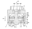
- FIG. 7 is a cross-sectional view taken along line A1-A1 of FIG. It is a partially expanded sectional view of the water discharging unit of FIG.
- the inventors of the present invention obtained the following knowledge as a result of diligent studies to make the length of the water film longer, to make the film thickness of the water film more uniform, and to make the length of the water film longer. It was.
- the present inventors have proposed that the length of the water film in the conventional shower apparatus is a major factor that the width dimension of the water discharge channel near the water discharge port is also uneven. I got a good knowledge. That is, in the conventional shower apparatus, the casing and the annular member that form the water discharge flow path have an assembled structure, and play is provided in the connection portion (for example, a screwing portion) for easy assembly. Due to this play, the central axis of the casing and the annular member shifts, and a portion where the casing and the annular member approach each other is generated, and on the opposite side, a portion where the casing and the annular member separate from each other is generated.
- the connection portion for example, a screwing portion
- the minimum width dimension of the water discharge flow path is 0.2 mm.
- the maximum width of the water discharge channel is 0.4 mm.
- the present inventors have found a configuration in which the water discharge channel near the water discharge port is tapered and the width dimension of the water discharge channel is uniform over the entire circumference. According to this configuration, the film thickness of the water film can be made more uniform, and the length of the water film can be increased to a desired level. Based on these new findings, the present inventors have reached the following invention.
- the shower head body A water discharge unit attached to the tip of the shower head body;
- a shower device comprising:
- the water discharge unit is A casing connected to the showerhead body;
- An annular member disposed inside the casing, wherein a water discharge passage for discharging water supplied through the shower head body as a water film between an inner peripheral surface of the casing and an outer peripheral surface of the annular member.
- An annular member configured to form; A water sprinkling member that is disposed inside the annular member and discharges water supplied through the shower head body as a shower-like water flow, With The inner peripheral surface of the casing and the outer peripheral surface of the annular member have a tapered portion that is inclined or curved so that the diameter of the water discharge channel increases toward the water discharge port, and at least from the water discharge port in the water discharge direction.
- a shower device configured so that the width dimension of the water discharge channel is uniform over the entire circumference in a preset section on the upstream side.
- the shower device according to the first aspect, wherein the preset section is a section having a length of more than half of the tapered portion.
- the water sprinkling member and the casing are detachably attached to each other with an inlay structure upstream of the annular member in the water discharge direction.
- the described shower apparatus is provided.
- the water sprinkling member has a shower water discharge portion provided with a plurality of water sprinkling holes, The outer peripheral part of the shower water spouting part is connected to the inner peripheral part of the annular member,
- the shower device according to any one of the first to third aspects is provided, wherein an inner peripheral portion of the annular member is configured to expose a surface on the upstream side in the water discharge direction of the shower water discharge portion. .
- annular member are attached to each other by the spigot structure,
- the shower apparatus as described in a 4th aspect is provided. To do.
- the shower apparatus according to any one of the first to third aspects, wherein the watering member and the annular member are integrally configured.
- the water discharge flow path is located upstream of the preset section in the water discharge direction.
- the shower apparatus according to any one of the first to sixth aspects, wherein at least three spacers are provided at equal intervals or substantially equal intervals in order to maintain the width dimension.
- the upstream end and the downstream end in the water discharge direction of the spacer are shorter in width than their intermediate portions. provide.
- the inner peripheral surface of the casing and the outer peripheral surface of the annular member each have a straight portion connected to the tapered portion on the upstream side in the water discharge direction, and between the straight portions.
- FIG. 1 is a side view of a shower device according to an embodiment of the present invention.
- the shower apparatus according to the present embodiment is an apparatus used in a kitchen, a washroom, and the like.
- the shower device 1 includes a shower head main body 2 and a water discharge unit 3 attached to the tip 2 ⁇ / b> A of the shower head main body 2.
- a water supply passage (not shown) for supplying water (including hot water) to the water discharge unit 3 is provided inside the shower head main body 2.
- the water discharge unit 3 is configured to discharge water supplied through the water supply passage of the shower head body 2 toward, for example, the bottom surface of the sink.
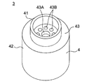
- FIG. 2 is a perspective view of the water discharge unit 3 as viewed obliquely from above.
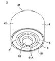
- FIG. 3 is a perspective view of the water discharge unit 3 as viewed obliquely from below.
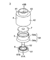
- FIG. 4 is an exploded perspective view of the water discharge unit 3 as viewed obliquely from above.
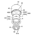
- FIG. 5 is an exploded perspective view of the water discharge unit 3 as viewed obliquely from below.
- FIG. 6 is a bottom view of the water discharge unit 3.
- 7 is a cross-sectional view taken along line A1-A1 of FIG.
- the water discharge unit 3 includes a casing 4, an annular member 5 disposed inside the casing 4, and a water sprinkling member 6 disposed inside the annular member 5.
- the casing 4 is a member that forms the outer shell of the water discharge unit 3, as shown in FIG.
- the casing 4 has a small diameter cylindrical portion 41, a large diameter cylindrical portion 42, and a disc portion 43.
- the small diameter cylindrical portion 41 is detachably attached to the distal end portion 2A of the shower head main body 2.
- the large-diameter cylindrical portion 42 has a larger diameter than the small-diameter cylindrical portion 41 and is disposed coaxially with the small-diameter cylindrical portion 41.
- the disc part 43 is connected to the lower end part of the small diameter cylindrical part 41 and the upper end part of the large diameter cylindrical part 42.
- the disc portion 43 is provided with a center hole 43A and a plurality of water supply holes 43B around the center hole 43A in a region surrounded by the small diameter cylindrical portion 41 in plan view.
- the center hole 43A is a perfect circular hole, and is provided so that the center is positioned on the center axis C1 of the small diameter cylindrical portion 41 and the large diameter cylindrical portion 42 as shown in FIG.
- the water supply hole 43B has a smaller diameter than the central hole 43A, and is provided so as to be in fluid communication with the water supply flow path of the shower head body 2.
- the annular member 5 is disposed inside the large diameter cylindrical portion 42. Between the inner peripheral surface 42A of the large-diameter cylindrical portion 42 and the outer peripheral surface 5A of the annular member 5, an annular water discharge channel F1 that discharges water supplied through the shower head body 2 as a water film is formed. .
- the inner peripheral surface 42A of the large-diameter cylindrical portion 42 and the outer peripheral surface 5A of the annular member 5 are each formed in a perfect circle shape in plan view.
- the inner peripheral surface 42A of the large-diameter cylindrical portion 42 and the outer peripheral surface 5A of the annular member 5 have tapered portions 42Aa and 5Aa that are inclined so that the diameter of the water discharge channel F1 increases toward the water discharge port S1. ing.
- the tapered portions 42Aa and 5Aa are configured so that the width dimension of the water discharge channel F1 is uniform over the entire circumference at least in a preset section upstream from the water discharge port S1 in the water discharge direction D1.
- the “width dimension” refers to a dimension in a direction orthogonal to the central axis C1 shown in FIG.
- the “width dimension” is, for example, 0.3 mm to 0.5 mm.
- the “preset section” is, for example, a section having a length more than half of the taper portions 42Aa and 5Aa.
- the “preset section” is a section of the entire length of the tapered portions 42Aa and 5Aa.
- the lengths of the tapered portions 42Aa and 5Aa are, for example, 6 mm to 7 mm.
- the inclination angle of the taper portions 42Aa and 5Aa with respect to the central axis C1 is, for example, 15 degrees to 40 degrees.
- the inclination angles of the taper portions 42Aa and 5Aa with respect to the central axis C1 are set within a range of 25 degrees to 35 degrees.
- the term “uniform” is not limited to being completely uniform, but allows a slight manufacturing tolerance (for example, a level of less than 0.1 mm).
- the inner peripheral surface 42A of the large-diameter cylindrical portion 42 and the outer peripheral surface 5A of the annular member 5 respectively have linear portions 42Ab and 5Ab connected to the tapered portions 42Aa and 5Aa on the upstream side in the water discharge direction D1.
- the straight portions 42Ab and 5Ab are formed in parallel to the central axis C1 of the small diameter cylindrical portion 41 and the large diameter cylindrical portion 42.
- the length of the straight portions 42Ab and 5Ab is, for example, 10 mm.
- the water sprinkling member 6 is configured to discharge water supplied through the shower head body 2 as a shower-like water flow.
- the water sprinkling member 6 includes a shower water discharger 61 provided with a plurality of water spray holes 61 ⁇ / b> A, and a central shaft 62 provided coaxially with the central axis C ⁇ b> 1 and connected to the center of the shower water discharger 61. ing.
- the shower water discharge part 61 is formed in a disk shape.
- the plurality of water spray holes 61A are provided so as to penetrate the shower water discharger 61 in the thickness direction.
- the outer periphery of the shower water discharger 61 is connected to the inner periphery of the annular member 5.
- the outer peripheral portion of the shower water discharger 61 and the inner peripheral portion of the annular member 5 can be attached to and detached from each other with an inlay structure so as to be fitted with less play without providing play such as screwing. Is attached.
- the shower water discharger 61 and the center shaft 62 are integrally configured.
- the center shaft 62 is configured such that the lower end portion passes through the center portion of the shower water discharger 61 and is exposed downward. Further, the upper end portion of the center shaft 62 is inserted into the center hole 43 ⁇ / b> A of the disc portion 43 and connected to the casing 4 on the upstream side in the water discharge direction D ⁇ b> 1 from the annular member 5.
- the upper end portion of the center shaft 62 and the disc portion 43 of the casing 4 can be attached to and detached from each other with an inlay structure so as to be fitted with less play without providing play such as screwing. It is attached.
- a flat plate ring-shaped rectifying network 7 is attached to an intermediate portion of the center shaft 62 so as to face the upstream surface 61B in the water discharge direction D1 of the shower water discharge portion 61.
- the rectifying net 7 is arranged inside the annular member 5 and is configured to rectify the water that has passed through the water supply hole 43 ⁇ / b> B of the disc portion 43 and supply the water to the shower water discharger 61.
- the water supplied to the water discharge unit 3 through the water supply passage of the shower head body 2 flows into the internal space of the large-diameter cylindrical portion 42 through the plurality of water supply holes 43B of the disc portion 43.
- the water that has flowed into the internal space of the large-diameter cylindrical portion 42 passes through the rectifying network 7 and is rectified and supplied to the shower water discharger 61.
- the water supplied to the shower water discharger 61 passes through the plurality of sprinkling holes 61 ⁇ / b> A and is discharged downward as a shower-like water flow below the water discharge unit 3.
- the water flowing into the water discharge channel F1 is discharged as a circular water film from the water outlet S1 around the shower water discharged as a shower-like water flow, and absorbs the water scattered by hitting tableware, a sink, etc. inside the water film To do. Thereby, it is suppressed that water splashing occurs outside the water film.
- the water flowing into the water discharge flow path F1 flows along the taper portions 42Aa and 5Aa, so that the water discharge port S1 serves as an annular water film that is inclined away from the central axis C1 toward the downstream side in the water discharge direction D1.
- the water is discharged from.
- the width dimension of the water discharge flow path F1 is configured to be uniform over the entire circumference in a preset section upstream from the water discharge S1 in the water discharge direction D1, the water discharge from the water outlet S1.
- the film thickness of the discharged water film becomes more uniform over the entire circumference.
- the water film can be prevented from joining the shower water discharge, and the length of the water film can be made longer (for example, 20 cm or more).
- the shower device 1 according to the present embodiment is configured so that the water discharge flow path F1 spreads out in the vicinity of the water discharge port S1 and the width dimension is uniform over the entire circumference. According to this configuration, the thickness of the water film can be made more uniform and the length of the water film can be made longer.
- the shower apparatus 1 which concerns on this embodiment, it is comprised so that the width dimension of the area of the length more than half of taper part 42Aa and 5Aa and the water discharge flow path F1 may become uniform. According to this configuration, the film thickness of the water film can be made more uniform, and the length of the water film can be further increased.
- the water sprinkling member 6 and the casing 4 are detachably attached to each other with an inlay structure upstream of the annular member 5 in the water discharging direction D1. According to this configuration, it is possible to improve the maintainability and to suppress the axial displacement, so that the width dimension of the water discharge flow path F1 can be made more uniform over the entire circumference.
- the outer peripheral part of the shower water discharging part 61 and the inner peripheral part of the annular member 5 are attached to each other by the spigot structure so that attachment or detachment is possible. According to this configuration, it is possible to improve the maintainability and to suppress the axial displacement, so that the width dimension of the water discharge flow path F1 can be made more uniform over the entire circumference.
- the inner peripheral part of the annular member 5 is configured to expose the upstream surface 61 ⁇ / b> B in the water discharge direction D ⁇ b> 1 in the shower water discharge part 61.
- the inner peripheral portion of the annular member 5 is preferably configured to have a gap CL between the inner surface portion of the shower water discharge portion 61 and the surface 61B. According to this configuration, when a part of the inner peripheral portion of the annular member 5 is in contact with the surface 61B of the shower water discharger 61, the shower water discharger 61 can be prevented from being inclined with respect to the central axis C1. As a result, the width dimension of the water discharge flow path F1 can be made more uniform over the entire circumference.
- the width dimension of the water discharge flow path F1 is set between the inner peripheral surface 42A of the large diameter cylindrical portion 42 and the outer peripheral surface 5A of the annular member 5 on the upstream side in the water discharge direction D1 with respect to the preset section.
- at least three spacers may be provided at equal intervals or substantially equal intervals.
- the width dimension of the water discharge channel F1 can be made more uniform over the entire circumference, and the width dimension of the water discharge channel F1 can be prevented from changing over time.
- each spacer may be provided between the straight portions 42Ab and 5Ab.
- the distance from each spacer to the water discharge port S1 becomes long, it is possible to suppress the water flowing through the water discharge flow channel F1 from reaching the water discharge port S1 in a state where the water is divided by the spacer.
- the film thickness can be made more uniform. Note that the length of the spacer in the water discharge direction D1 is, for example, 2 mm to 3 mm.
- the width dimension W1 of the upstream end of the water discharge direction D1 and the width dimension W2 of the downstream end of each spacer may be shorter than the width dimension W3 of the intermediate portion. preferable. According to this structure, it can suppress that the water which flows through the water discharge flow path F1 reaches
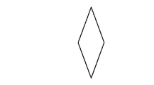
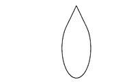
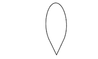
- the spacer is not limited to the shape shown in FIG. 9A, and may be, for example, a rhombus as shown in FIG. 9B. Further, the spacer may have a shape in which at least one end is rounded as shown in FIGS. 9C and 9D. According to this configuration, the water flowing through the water discharge flow path F1 can be made to flow more along the spacer, and the water can be prevented from being divided by the spacer.
- the casing 4, the annular member 5, and the watering member 6 are injection-molded with a filler-containing resin. According to this structure, since each member can make a dimensional accuracy high, the width dimension of the water discharge flow path F1 can be made more uniform over a perimeter.
- the casing 4, the annular member 5, and the water sprinkling member 6 are produced by cutting. According to this structure, since each member can make a dimensional accuracy high, the width dimension of the water discharge flow path F1 can be made more uniform over a perimeter.
- the tapered portions 42Aa and 5Aa are formed so as to be inclined so that the diameter of the water discharge channel F1 increases toward the water discharge port S1, but the present invention is not limited to this.
- the tapered portions 42Aa and 5Aa may be formed to be curved so that the diameter of the water discharge channel F1 increases toward the water discharge port S1.
- the “preset section” is a section of the entire length of the tapered portions 42Aa and 5Aa, but the present invention is not limited to this.
- the “preset section” may be a section extending over the entire length of the water discharge channel F1. That is, the width dimension of the water discharge flow path F1 may be configured to be uniform over the entire length of the water discharge direction D1.
- the water sprinkling member 6 and the annular member 5 are detachably attached to each other with an inlay structure, but the present invention is not limited to this.
- the water sprinkling member 6 and the annular member 5 may be integrally configured. In this case, it is possible to further suppress axial misalignment between the water sprinkling member 6 and the annular member 5, and it is possible to make the width dimension of the water discharge flow path F1 more uniform over the entire circumference.
Landscapes
- Health & Medical Sciences (AREA)
- Public Health (AREA)
- Life Sciences & Earth Sciences (AREA)
- Engineering & Computer Science (AREA)
- Hydrology & Water Resources (AREA)
- Water Supply & Treatment (AREA)
- Epidemiology (AREA)
- General Health & Medical Sciences (AREA)
- Nozzles (AREA)
- Domestic Plumbing Installations (AREA)
Abstract
水膜の膜厚をより均一にするとともに、水膜の長さをより長くすることができるシャワー装置を提供する。本発明に係るシャワー装置は、シャワーヘッド本体に接続されたケーシングと、ケーシングの内側に配置された環状部材であって、ケーシングの内周面と環状部材の外周面との間で給水された水を水膜として吐水する吐水流路を形成する環状部材と、環状部材の内側に配置され、給水された水をシャワー状の水流として吐水する散水部材とを備え、ケーシングの内周面と環状部材の外周面とは、吐水流路の直径が吐水口に向かうに従い大きくなるように傾斜又は湾曲するテーパ部を有し、少なくとも吐水口から吐水方向の上流側の予め設定された区間において吐水流路の幅寸法が全周に亘って均一に構成されている。
Description
本発明は、複数の散水孔からシャワー状の水流として吐水されるシャワー吐水の周囲に環状の水膜を形成可能なシャワー装置に関する。
従来、台所、洗面所等に使用されるシャワー装置においては、シャワー吐水が食器やシンク等に当たって飛散し周囲を意図せず濡らしてしまう、いわゆる「水撥ね」が生じ得る。この水撥ねを抑えるため、シャワー吐水の周囲に環状の水膜を形成する装置が知られている。この装置によれば、食器やシンク等に当たって飛散した水が水膜に吸収されることで、水膜の外側で水撥ねが発生することを抑えることができる。
しかしながら、前記装置においては、水膜の吐水口から離れるほど、表面張力によって水膜の直径が小さくなって、水膜とシャワー吐水とが合流してしまうという課題がある。すなわち、吐水口からの水膜の長さが短く、十分に水撥ねを抑えることができないという課題がある。
この課題を解決するため、特許文献1には、吐水口に繋がる吐水流路をテーパ状に形成して、シャワー吐水から離れる方向に水膜を吐水するとともに、環状の吐水口の一部に突起部を設けて水膜の一部を分断するようにした構成が開示されている。この構成によれば、分断した部分で表面張力を抑えることができ、水膜の長さをより長くすることができる。
しかしながら、特許文献1のシャワー装置においては、水膜の一部を分断するため、分断した部分は、水撥ねを抑えることができないとともに、水膜の厚みが不均一になる。従って、従来のシャワー装置においては、水膜の膜厚をより均一にするとともに、水膜の長さをより長くするという観点において、未だ改善の余地がある。
本発明の目的は、前記課題を解決することにあって、水膜の長さをより長くするとともに、水膜の膜厚をより均一にすることができるシャワー装置を提供することにある。
前記目的を達成するために、本発明に係るシャワー装置は、シャワーヘッド本体と、
前記シャワーヘッド本体の先端部に取り付けられた吐水ユニットと、
を備えるシャワー装置であって、
前記吐水ユニットは、
前記シャワーヘッド本体に接続されたケーシングと、
前記ケーシングの内側に配置された環状部材であって、前記ケーシングの内周面と前記環状部材の外周面との間で前記シャワーヘッド本体を通じて給水された水を水膜として吐水する吐水流路を形成するように構成された環状部材と、
前記環状部材の内側に配置され、前記シャワーヘッド本体を通じて給水された水をシャワー状の水流として吐水する散水部材と、
を備え、
前記ケーシングの内周面と前記環状部材の外周面とは、前記吐水流路の直径が吐水口に向かうに従い大きくなるように傾斜又は湾曲するテーパ部を有し、少なくとも前記吐水口から吐水方向の上流側の予め設定された区間において前記吐水流路の幅寸法が全周に亘って均一になるように構成されている。
前記シャワーヘッド本体の先端部に取り付けられた吐水ユニットと、
を備えるシャワー装置であって、
前記吐水ユニットは、
前記シャワーヘッド本体に接続されたケーシングと、
前記ケーシングの内側に配置された環状部材であって、前記ケーシングの内周面と前記環状部材の外周面との間で前記シャワーヘッド本体を通じて給水された水を水膜として吐水する吐水流路を形成するように構成された環状部材と、
前記環状部材の内側に配置され、前記シャワーヘッド本体を通じて給水された水をシャワー状の水流として吐水する散水部材と、
を備え、
前記ケーシングの内周面と前記環状部材の外周面とは、前記吐水流路の直径が吐水口に向かうに従い大きくなるように傾斜又は湾曲するテーパ部を有し、少なくとも前記吐水口から吐水方向の上流側の予め設定された区間において前記吐水流路の幅寸法が全周に亘って均一になるように構成されている。
本発明に係るシャワー装置によれば、水膜の膜厚をより均一にするとともに、水膜の長さをより長くすることができる。
(本発明の基礎となった知見)
本発明者らは、水膜の長さをより長くするとともに、水膜の膜厚をより均一にするとともに、水膜の長さをより長くするため、鋭意検討した結果、以下の知見を得た。
本発明者らは、水膜の長さをより長くするとともに、水膜の膜厚をより均一にするとともに、水膜の長さをより長くするため、鋭意検討した結果、以下の知見を得た。
水膜の膜厚を均一にするためには、水膜の一部を分断せず、環状の水膜を吐水するように構成することが好ましいと考えられる。環状の水膜を吐水するように構成されたシャワー装置は、従来から存在する。しかしながら、当該従来のシャワー装置においては、前述したように、水膜の表面張力によって、水膜とシャワー吐水とが合流し、吐水口からの水膜の長さが短いという課題がある。
これに対して、本発明者らは、従来のシャワー装置において水膜の長さが短くなるのは、吐水口付近の吐水流路の幅寸法が不均一であることも大きな要因であるという新規な知見を得た。すなわち、従来のシャワー装置においては、吐水流路を形成するケーシングと環状部材とを組み立て構造とし、組み立てを容易にするために接続部(例えば、ネジ止め部)に遊びを設けている。この遊びによって、ケーシングと環状部材との中心軸がずれ、ケーシングと環状部材とが互いに近づく部分が生じるとともに、その反対側ではケーシングと環状部材とが互いに離れる部分が生じる。例えば、吐水口付近において、吐水流路の平均幅寸法が0.3mmであり、ケーシングと環状部材との中心軸のずれが0.1mmである場合、吐水流路の最小幅寸法は0.2mmとなり、吐水流路の最大幅寸法は0.4mmとなる。この場合、吐水口から吐水される水膜において膜厚が厚い部分と膜厚が薄い部分とが生じる。表面張力も膜厚によって変化するので、膜厚に偏りがあると、表面張力のバランスが崩れて、水膜が均一に広がらずに偏りが生じる。その結果、吐水口からの水膜の長さが短くなる。
そこで、本発明者らは、鋭意検討した結果、吐水口付近の吐水流路をテーパ状に広げるとともに、当該吐水流路の幅寸法を全周に亘って均一した構成を見出した。この構成によれば、水膜の膜厚をより均一にすることができ、水膜の長さを所望のレベルまで長くすることが可能になる。これらの新規な知見に基づき、本発明者らは、以下の発明に至った。
本発明の第1態様によれば、シャワーヘッド本体と、
前記シャワーヘッド本体の先端部に取り付けられた吐水ユニットと、
を備えるシャワー装置であって、
前記吐水ユニットは、
前記シャワーヘッド本体に接続されたケーシングと、
前記ケーシングの内側に配置された環状部材であって、前記ケーシングの内周面と前記環状部材の外周面との間で前記シャワーヘッド本体を通じて給水された水を水膜として吐水する吐水流路を形成するように構成された環状部材と、
前記環状部材の内側に配置され、前記シャワーヘッド本体を通じて給水された水をシャワー状の水流として吐水する散水部材と、
を備え、
前記ケーシングの内周面と前記環状部材の外周面とは、前記吐水流路の直径が吐水口に向かうに従い大きくなるように傾斜又は湾曲するテーパ部を有し、少なくとも前記吐水口から吐水方向の上流側の予め設定された区間において前記吐水流路の幅寸法が全周に亘って均一になるように構成されている、シャワー装置を提供する。
前記シャワーヘッド本体の先端部に取り付けられた吐水ユニットと、
を備えるシャワー装置であって、
前記吐水ユニットは、
前記シャワーヘッド本体に接続されたケーシングと、
前記ケーシングの内側に配置された環状部材であって、前記ケーシングの内周面と前記環状部材の外周面との間で前記シャワーヘッド本体を通じて給水された水を水膜として吐水する吐水流路を形成するように構成された環状部材と、
前記環状部材の内側に配置され、前記シャワーヘッド本体を通じて給水された水をシャワー状の水流として吐水する散水部材と、
を備え、
前記ケーシングの内周面と前記環状部材の外周面とは、前記吐水流路の直径が吐水口に向かうに従い大きくなるように傾斜又は湾曲するテーパ部を有し、少なくとも前記吐水口から吐水方向の上流側の予め設定された区間において前記吐水流路の幅寸法が全周に亘って均一になるように構成されている、シャワー装置を提供する。
本発明の第2態様によれば、前記予め設定された区間は、前記テーパ部の半分以上の長さの区間である、第1態様に記載のシャワー装置を提供する。
本発明の第3態様によれば、前記散水部材と前記ケーシングとは、前記環状部材よりも前記吐水方向の上流側において、インロー構造で互いに着脱可能に取り付けられている、第1又は2態様に記載のシャワー装置を提供する。
本発明の第4態様によれば、前記散水部材は、複数の散水孔が設けられたシャワー吐水部を有し、
前記シャワー吐水部の外周部は、前記環状部材の内周部に接続され、
前記環状部材の内周部は、前記シャワー吐水部における前記吐水方向の上流側の表面を露出させるように構成されている、第1~3態様のいずれか1つに記載のシャワー装置を提供する。
前記シャワー吐水部の外周部は、前記環状部材の内周部に接続され、
前記環状部材の内周部は、前記シャワー吐水部における前記吐水方向の上流側の表面を露出させるように構成されている、第1~3態様のいずれか1つに記載のシャワー装置を提供する。
本発明の第5態様によれば、前記シャワー吐水部の外周部と前記環状部材の内周部とは、インロー構造で互いに着脱可能に取り付けられている、第4態様に記載のシャワー装置を提供する。
本発明の第6態様によれば、前記散水部材と前記環状部材とは、一体構成されている、第1~3態様のいずれか1つに記載のシャワー装置を提供する。
本発明の第7態様によれば、前記ケーシングの内周面と前記環状部材の外周面との間には、前記予め設定された区間よりも前記吐水方向の上流側において、前記吐水流路の幅寸法を維持するために、少なくとも3つのスペーサが等間隔又は略等間隔に設けられている、第1~6態様のいずれか1つに記載のシャワー装置を提供する。
本発明の第8態様によれば、前記スペーサにおける前記吐水方向の上流側の端部及び下流側の端部は、それらの中間部よりも幅寸法が短い、第7態様に記載のシャワー装置を提供する。
本発明の第9態様によれば、前記ケーシングの内周面と前記環状部材の外周面とは、前記吐水方向の上流側で前記テーパ部に繋がる直線部をそれぞれ有し、当該直線部の間に前記少なくとも3つのスペーサが設けられている、第7又は8態様に記載のシャワー装置を提供する。
以下、本発明の実施形態について、図面を参照しながら説明する。なお、本発明は、以下の実施形態に限定されるものではない。
《実施形態》
図1は、本発明の実施形態に係るシャワー装置の側面図である。本実施形態に係るシャワー装置は、台所、洗面所等に使用される装置である。
図1は、本発明の実施形態に係るシャワー装置の側面図である。本実施形態に係るシャワー装置は、台所、洗面所等に使用される装置である。
図1に示すように、本実施形態に係るシャワー装置1は、シャワーヘッド本体2と、シャワーヘッド本体2の先端部2Aに取り付けられた吐水ユニット3とを備えている。
シャワーヘッド本体2の内部には、吐水ユニット3に水(湯を含む)を給水するための給水流路(図示せず)が設けられている。吐水ユニット3は、シャワーヘッド本体2の給水流路を通じて給水された水を、例えばシンクの底面に向けて吐水するように構成されている。
図2は、吐水ユニット3を斜め上方から見た斜視図である。図3は、吐水ユニット3を斜め下方から見た斜視図である。図4は、吐水ユニット3を斜め上方から見た分解斜視図である。図5は、吐水ユニット3を斜め下方から見た分解斜視図である。図6は、吐水ユニット3の底面図である。図7は、図6のA1-A1線断面図である。
吐水ユニット3は、ケーシング4と、ケーシング4の内側に配置された環状部材5と、環状部材5の内側に配置された散水部材6とを備えている。
ケーシング4は、図2に示すように、吐水ユニット3の外郭を構成する部材である。本実施形態において、ケーシング4は、小径円筒部41と、大径円筒部42と、円板部43とを有している。
小径円筒部41は、シャワーヘッド本体2の先端部2Aに着脱可能に取り付けられる。大径円筒部42は、小径円筒部41よりも大きな直径を有し、小径円筒部41に対して同軸に配置されている。円板部43は、小径円筒部41の下端部と大径円筒部42の上端部とに接続されている。円板部43には、平面視において小径円筒部41に囲まれた領域に、中心穴43Aと、中心穴43Aの周囲に複数の給水孔43Bとが設けられている。中心穴43Aは、真円状の穴であり、図7に示すように、中心が小径円筒部41及び大径円筒部42の中心軸C1上に位置するように設けられている。給水孔43Bは、中心穴43Aよりも小さい直径を有し、シャワーヘッド本体2の給水流路と流体連通するように設けられている。
環状部材5は、大径円筒部42の内側に配置されている。大径円筒部42の内周面42Aと環状部材5の外周面5Aとの間には、シャワーヘッド本体2を通じて給水された水を水膜として吐水する環状の吐水流路F1が形成されている。本実施形態において、大径円筒部42の内周面42A及び環状部材5の外周面5Aは、それぞれ平面視において真円状に形成されている。
また、大径円筒部42の内周面42Aと環状部材5の外周面5Aとは、吐水流路F1の直径が吐水口S1に向かうに従い大きくなるように傾斜するテーパ部42Aa,5Aaを有している。テーパ部42Aa,5Aaは、少なくとも吐水口S1から吐水方向D1の上流側の予め設定された区間において吐水流路F1の幅寸法が全周に亘って均一になるように構成されている。
ここで、「幅寸法」とは、図8に示す中心軸C1に対して直交する方向の寸法をいう。「幅寸法」は、例えば、0.3mm~0.5mmである。また、「予め設定された区間」は、例えば、テーパ部42Aa,5Aaの半分以上の長さの区間である。本実施形態において、「予め設定された区間」は、テーパ部42Aa,5Aaの全体の長さの区間である。テーパ部42Aa,5Aaの長さは、例えば、6mm~7mmである。また、中心軸C1に対するテーパ部42Aa,5Aaの傾斜角度は、例えば、15度~40度である。本実施形態において、中心軸C1に対するテーパ部42Aa,5Aaの傾斜角度は、25度~35度の範囲内で設定されている。また、「均一」とは、完全に均一であることに限定されるものではなく、僅かな製造上の公差等(例えば、0.1mm未満のレベル)を許容するものである。
また、大径円筒部42の内周面42Aと環状部材5の外周面5Aとは、吐水方向D1の上流側でテーパ部42Aa,5Aaに繋がる直線部42Ab,5Abをそれぞれ有している。直線部42Ab,5Abは、小径円筒部41及び大径円筒部42の中心軸C1に対して平行に形成されている。直線部42Ab,5Abの長さは、例えば、10mmである。
散水部材6は、シャワーヘッド本体2を通じて給水された水をシャワー状の水流として吐水するように構成されている。本実施形態において、散水部材6は、複数の散水孔61Aが設けられたシャワー吐水部61と、中心軸C1と同軸に設けられ、シャワー吐水部61の中心に接続された中心シャフト62とを備えている。
シャワー吐水部61は、円板状に形成されている。複数の散水孔61Aは、シャワー吐水部61を厚み方向に貫通するように設けられている。シャワー吐水部61の外周部は、環状部材5の内周部に接続されている。本実施形態において、シャワー吐水部61の外周部と環状部材5の内周部とは、ネジ止めのような遊びを設けることなく、よりガタつきなく嵌合するように、インロー構造で互いに着脱可能に取り付けられている。
シャワー吐水部61と中心シャフト62とは、一体構成されている。中心シャフト62は、下端部がシャワー吐水部61の中心部を貫通して下方に露出するように構成されている。また、中心シャフト62は、環状部材5よりも吐水方向D1の上流側において、上端部が円板部43の中心穴43Aに挿入されてケーシング4に接続されている。本実施形態において、中心シャフト62の上端部とケーシング4の円板部43とは、ネジ止めのような遊びを設けることなく、よりガタつきなく嵌合するように、インロー構造で互いに着脱可能に取り付けられている。
本実施形態において、中心シャフト62の中間部には、シャワー吐水部61における吐水方向D1の上流側の表面61Bと対向するように平板リング状の整流網7が取り付けられている。整流網7は、環状部材5の内側に配置され、円板部43の給水孔43Bを通過した水を整流してシャワー吐水部61へ給水するように構成されている。
次に、図7を参照しつつ、本実施形態に係るシャワー装置1における水の流れについて説明する。
まず、シャワーヘッド本体2の給水流路を通じて吐水ユニット3に給水された水は、円板部43の複数の給水孔43Bを通じて大径円筒部42の内部空間に流入する。
大径円筒部42の内部空間に流入した水は、整流網7を通過して整流され、シャワー吐水部61へ給水される。シャワー吐水部61に給水された水は、複数の散水孔61Aを通過し、吐水ユニット3の下方へシャワー状の水流として吐水される。
大径円筒部42の内部空間に流入した水の一部は、環状の吐水流路F1に流入する。吐水流路F1に流入した水は、シャワー状の水流として吐水されるシャワー吐水の周囲に吐水口S1から環状の水膜として吐水され、水膜の内側で食器やシンク等に当たって飛散した水を吸収する。これにより、水膜の外側で水撥ねが発生することが抑えられる。
また、吐水流路F1に流入した水は、テーパ部42Aa,5Aaに沿って流れることで、吐水方向D1の下流側に向かうに従い中心軸C1から離れるように傾斜する環状の水膜として吐水口S1から吐水される。また、このとき、吐水口S1から吐水方向D1の上流側の予め設定された区間において吐水流路F1の幅寸法が全周に亘って均一になるように構成されているので、吐水口S1から吐水される水膜の膜厚は全周に亘ってより均一になる。その結果、水膜がシャワー吐水と合流することを抑えて、水膜の長さをより長く(例えば、20cm以上)することができる。なお、シャワー装置1を台所又は洗面所で使用する場合、水膜の長さは15cm以上であることが求められる。
本実施形態に係るシャワー装置1においては、吐水口S1付近において、吐水流路F1がテーパ状に広がるとともに幅寸法が全周に亘って均一になるように構成されている。この構成によれば、水膜の膜厚をより均一にするとともに、水膜の長さをより長くすることができる。
また、本実施形態に係るシャワー装置1においては、テーパ部42Aa,5Aaの半分以上の長さの区間、吐水流路F1の幅寸法が全周に亘って均一になるように構成されている。この構成によれば、水膜の膜厚を一層均一にするとともに、水膜の長さを一層長くすることができる。
また、本実施形態に係るシャワー装置1においては、散水部材6とケーシング4とは、環状部材5よりも吐水方向D1の上流側において、インロー構造で互いに着脱可能に取り付けられている。この構成によれば、メンテナンス性を向上させるとともに、軸ズレを抑えることができるので吐水流路F1の幅寸法を全周に亘って一層均一にすることができる。
また、本実施形態に係るシャワー装置1によれば、シャワー吐水部61の外周部と環状部材5の内周部とは、インロー構造で互いに着脱可能に取り付けられている。この構成によれば、メンテナンス性を向上させるとともに、軸ズレを抑えることができるので吐水流路F1の幅寸法を全周に亘って一層均一にすることができる。
なお、環状部材5の内周部は、シャワー吐水部61における吐水方向D1の上流側の表面61Bを露出させるように構成されることが好ましい。例えば、図8に示すように、環状部材5の内周部は、シャワー吐水部61の表面61Bとの間に隙間CLを有するように構成されることが好ましい。この構成によれば、環状部材5の内周部の一部がシャワー吐水部61の表面61Bに接触することによって、シャワー吐水部61が中心軸C1に対して傾くことを抑えることができる。その結果、吐水流路F1の幅寸法を全周に亘って一層均一にすることができる。
また、大径円筒部42の内周面42Aと環状部材5の外周面5Aとの間には、前記予め設定された区間よりも吐水方向D1の上流側において、吐水流路F1の幅寸法を維持するために、少なくとも3つのスペーサが等間隔又は略等間隔に設けられてもよい。この構造によれば、吐水流路F1の幅寸法をより確実に全周に亘って均一にするとともに、吐水流路F1の幅寸法が経時的に変化することを抑えることができる。なお、この場合、各スペーサは、直線部42Ab,5Abの間に設けられてもよい。この構成によれば、各スペーサから吐水口S1までの距離が長くなるので、吐水流路F1を流れる水がスペーサによって分断された状態で吐水口S1に達することを抑えることができ、水膜の膜厚をより均一にすることができる。なお、スペーサの吐水方向D1の長さは、例えば2mm~3mmである。
また、図9Aに示すように、各スペーサにおける吐水方向D1の上流側の端部の幅寸法W1及び下流側の端部の幅寸法W2は、それらの中間部の幅寸法W3よりも短いことが好ましい。この構成によれば、吐水流路F1を流れる水がスペーサによって分断された状態で吐水口S1に達することを抑えることができ、水膜の膜厚をより均一にすることができる。
なお、スペーサは、図9Aに示す形状に限定されるものではなく、例えば、図9Bに示すように菱形であってもよい。また、スペーサは、図9C、図9Dに示すように少なくとも一方の端部が丸みを帯びた形状であってもよい。この構成によれば、吐水流路F1を流れる水を、よりスペーサに沿って流れるようにすることができ、当該水がスペーサによって分断されることを抑えることができる。
また、ケーシング4、環状部材5、及び散水部材6は、フィラー含有樹脂により射出成形されることが好ましい。この構成によれば、各部材は寸法精度を高くすることができるので、吐水流路F1の幅寸法を全周に亘って一層均一にすることができる。
また、ケーシング4、環状部材5、及び散水部材6は、切削加工により作製されることが好ましい。この構成によれば、各部材は寸法精度を高くすることができるので、吐水流路F1の幅寸法を全周に亘って一層均一にすることができる。
なお、本発明は前記実施形態に限定されるものではなく、その他種々の態様で実施できる。例えば、前記では、テーパ部42Aa,5Aaは、吐水流路F1の直径が吐水口S1に向かうに従い大きくなるように傾斜するよう形成されるものとしたが、本発明はこれに限定されない。例えば、テーパ部42Aa,5Aaは、吐水流路F1の直径が吐水口S1に向かうに従い大きくなるように湾曲するよう形成されてもよい。
また、前記では、「予め設定された区間」は、テーパ部42Aa,5Aaの全体の長さの区間であるものとしたが、本発明はこれに限定されない。例えば、「予め設定された区間」は、吐水流路F1の全長に亘る区間であってもよい。すなわち、吐水流路F1の幅寸法は、吐水方向D1の全長に亘って均一になるように構成されてもよい。
また、前記では、散水部材6と環状部材5とは、インロー構造で互いに着脱可能に取り付けられるものとしたが、本発明はこれに限定されない。例えば、散水部材6と環状部材5とは、一体構成されてもよい。この場合、散水部材6と環状部材5とが軸ズレすることをより抑えることができ、吐水流路F1の幅寸法を全周に亘って一層均一にすることができる。
本発明は、添付図面を参照しながら好ましい実施の形態に関連して充分に記載されているが、この技術に熟練した人々にとっては種々の変形や修正は明白である。そのような変形や修正は、添付した請求の範囲による本発明の範囲から外れない限りにおいて、その中に含まれると理解されるべきである。
1 シャワー装置
2 シャワーヘッド本体
2A 先端部
3 吐水ユニット
4 ケーシング
5 環状部材
5A 外周面
5Aa テーパ部
5Ab 直線部
6 散水部材
7 整流網
41 小径円筒部
42 大径円筒部
42A 内周面
42Aa テーパ部
42Ab 直線部
43 円板部
43A 中心穴
43B 給水孔
61 シャワー吐水部
61A 散水孔
61B 表面
62 中心シャフト
C1 中心軸
D1 吐水方向
F1 吐水流路
S1 吐水口
2 シャワーヘッド本体
2A 先端部
3 吐水ユニット
4 ケーシング
5 環状部材
5A 外周面
5Aa テーパ部
5Ab 直線部
6 散水部材
7 整流網
41 小径円筒部
42 大径円筒部
42A 内周面
42Aa テーパ部
42Ab 直線部
43 円板部
43A 中心穴
43B 給水孔
61 シャワー吐水部
61A 散水孔
61B 表面
62 中心シャフト
C1 中心軸
D1 吐水方向
F1 吐水流路
S1 吐水口
Claims (9)
- シャワーヘッド本体と、
前記シャワーヘッド本体の先端部に取り付けられた吐水ユニットと、
を備えるシャワー装置であって、
前記吐水ユニットは、
前記シャワーヘッド本体に接続されたケーシングと、
前記ケーシングの内側に配置された環状部材であって、前記ケーシングの内周面と前記環状部材の外周面との間で前記シャワーヘッド本体を通じて給水された水を水膜として吐水する吐水流路を形成するように構成された環状部材と、
前記環状部材の内側に配置され、前記シャワーヘッド本体を通じて給水された水をシャワー状の水流として吐水する散水部材と、
を備え、
前記ケーシングの内周面と前記環状部材の外周面とは、前記吐水流路の直径が吐水口に向かうに従い大きくなるように傾斜又は湾曲するテーパ部を有し、少なくとも前記吐水口から吐水方向の上流側の予め設定された区間において前記吐水流路の幅寸法が全周に亘って均一になるように構成されている、シャワー装置。 - 前記予め設定された区間は、前記テーパ部の半分以上の長さの区間である、請求項1に記載のシャワー装置。
- 前記散水部材と前記ケーシングとは、前記環状部材よりも前記吐水方向の上流側において、インロー構造で互いに着脱可能に取り付けられている、請求項1又は2に記載のシャワー装置。
- 前記散水部材は、複数の散水孔が設けられたシャワー吐水部を有し、
前記シャワー吐水部の外周部は、前記環状部材の内周部に接続され、
前記環状部材の内周部は、前記シャワー吐水部における前記吐水方向の上流側の表面を露出させるように構成されている、請求項1~3のいずれか1つに記載のシャワー装置。 - 前記シャワー吐水部の外周部と前記環状部材の内周部とは、インロー構造で互いに着脱可能に取り付けられている、請求項4に記載のシャワー装置。
- 前記散水部材と前記環状部材とは、一体構成されている、請求項1~3のいずれか1つに記載のシャワー装置。
- 前記ケーシングの内周面と前記環状部材の外周面との間には、前記予め設定された区間よりも前記吐水方向の上流側において、前記吐水流路の幅寸法を維持するために、少なくとも3つのスペーサが等間隔又は略等間隔に設けられている、請求項1~6のいずれか1つに記載のシャワー装置。
- 前記スペーサにおける前記吐水方向の上流側の端部及び下流側の端部は、それらの中間部よりも幅寸法が短い、請求項7に記載のシャワー装置。
- 前記ケーシングの内周面と前記環状部材の外周面とは、前記吐水方向の上流側で前記テーパ部に繋がる直線部をそれぞれ有し、当該直線部の間に前記少なくとも3つのスペーサが設けられている、請求項7又は8に記載のシャワー装置。
Priority Applications (1)
| Application Number | Priority Date | Filing Date | Title |
|---|---|---|---|
| JP2019568924A JPWO2019150798A1 (ja) | 2018-01-31 | 2018-12-17 | シャワー装置 |
Applications Claiming Priority (2)
| Application Number | Priority Date | Filing Date | Title |
|---|---|---|---|
| JP2018-014339 | 2018-01-31 | ||
| JP2018014339 | 2018-01-31 |
Publications (1)
| Publication Number | Publication Date |
|---|---|
| WO2019150798A1 true WO2019150798A1 (ja) | 2019-08-08 |
Family
ID=67478217
Family Applications (1)
| Application Number | Title | Priority Date | Filing Date |
|---|---|---|---|
| PCT/JP2018/046362 Ceased WO2019150798A1 (ja) | 2018-01-31 | 2018-12-17 | シャワー装置 |
Country Status (2)
| Country | Link |
|---|---|
| JP (1) | JPWO2019150798A1 (ja) |
| WO (1) | WO2019150798A1 (ja) |
Cited By (2)
| Publication number | Priority date | Publication date | Assignee | Title |
|---|---|---|---|---|
| JP2022006604A (ja) * | 2020-06-24 | 2022-01-13 | パナソニックIpマネジメント株式会社 | 水栓の吐水部構造およびそれを備える水栓 |
| JP2023080464A (ja) * | 2021-11-30 | 2023-06-09 | 株式会社Lixil | 吐水装置 |
Citations (4)
| Publication number | Priority date | Publication date | Assignee | Title |
|---|---|---|---|---|
| JPH0283047U (ja) * | 1988-12-12 | 1990-06-27 | ||
| JPH05140973A (ja) * | 1991-11-25 | 1993-06-08 | Hitachi Ltd | 流体用蛇口 |
| JP2007138662A (ja) * | 2005-11-22 | 2007-06-07 | Toto Ltd | シャワー装置 |
| JP2015226628A (ja) * | 2014-05-30 | 2015-12-17 | 株式会社Lixil | 吐水装置及び浴槽装置 |
-
2018
- 2018-12-17 WO PCT/JP2018/046362 patent/WO2019150798A1/ja not_active Ceased
- 2018-12-17 JP JP2019568924A patent/JPWO2019150798A1/ja active Pending
Patent Citations (4)
| Publication number | Priority date | Publication date | Assignee | Title |
|---|---|---|---|---|
| JPH0283047U (ja) * | 1988-12-12 | 1990-06-27 | ||
| JPH05140973A (ja) * | 1991-11-25 | 1993-06-08 | Hitachi Ltd | 流体用蛇口 |
| JP2007138662A (ja) * | 2005-11-22 | 2007-06-07 | Toto Ltd | シャワー装置 |
| JP2015226628A (ja) * | 2014-05-30 | 2015-12-17 | 株式会社Lixil | 吐水装置及び浴槽装置 |
Cited By (3)
| Publication number | Priority date | Publication date | Assignee | Title |
|---|---|---|---|---|
| JP2022006604A (ja) * | 2020-06-24 | 2022-01-13 | パナソニックIpマネジメント株式会社 | 水栓の吐水部構造およびそれを備える水栓 |
| JP7507431B2 (ja) | 2020-06-24 | 2024-06-28 | パナソニックIpマネジメント株式会社 | 水栓の吐水部構造およびそれを備える水栓 |
| JP2023080464A (ja) * | 2021-11-30 | 2023-06-09 | 株式会社Lixil | 吐水装置 |
Also Published As
| Publication number | Publication date |
|---|---|
| JPWO2019150798A1 (ja) | 2020-11-26 |
Similar Documents
| Publication | Publication Date | Title |
|---|---|---|
| CN203342966U (zh) | 一种用于水龙头的喷头组件 | |
| JP5168708B2 (ja) | シャワー装置 | |
| DK2540400T3 (en) | Full cone nozzle | |
| US7694897B2 (en) | Integrated multi-function showerhead | |
| CN106061617B (zh) | 具有多通道喷口出口单元的淋浴器 | |
| WO2019150798A1 (ja) | シャワー装置 | |
| CN109922890B (zh) | 喷淋头 | |
| TWI668403B (zh) | Fluid nozzle structure | |
| US10415219B2 (en) | Fluid restriction nozzle for hand washing | |
| JP3273198B2 (ja) | スコールシャワ用のシャワノズル | |
| JP7133885B1 (ja) | ミスト発生装置およびミスト発生装置を用いたシャワーヘッド | |
| JP7203538B2 (ja) | シャワーヘッド装置 | |
| JP2021134554A (ja) | 水栓装置 | |
| JP7025704B2 (ja) | 吐水装置 | |
| KR101337783B1 (ko) | 확산판을 구비한 샤워헤드 | |
| JP3898933B2 (ja) | 水栓の吐水口用整流器 | |
| JP6465836B2 (ja) | ノズル装置 | |
| JP7507431B2 (ja) | 水栓の吐水部構造およびそれを備える水栓 | |
| JP2010227181A (ja) | シャワーヘッド | |
| US10208881B2 (en) | Water-saving sheet and water-saving device having the same | |
| JP2020045803A (ja) | エジェクタ | |
| JP6749778B2 (ja) | シャワーヘッド | |
| WO2019187606A1 (ja) | 吐水装置および吐水方法 | |
| CN221989472U (zh) | 一种水流整流器 | |
| CN204583521U (zh) | 一种喷溅水出水装置 |
Legal Events
| Date | Code | Title | Description |
|---|---|---|---|
| 121 | Ep: the epo has been informed by wipo that ep was designated in this application |
Ref document number: 18903943 Country of ref document: EP Kind code of ref document: A1 |
|
| ENP | Entry into the national phase |
Ref document number: 2019568924 Country of ref document: JP Kind code of ref document: A |
|
| NENP | Non-entry into the national phase |
Ref country code: DE |
|
| 122 | Ep: pct application non-entry in european phase |
Ref document number: 18903943 Country of ref document: EP Kind code of ref document: A1 |