WO2019150598A1 - 磁石式プレート玩具 - Google Patents
磁石式プレート玩具 Download PDFInfo
- Publication number
- WO2019150598A1 WO2019150598A1 PCT/JP2018/026568 JP2018026568W WO2019150598A1 WO 2019150598 A1 WO2019150598 A1 WO 2019150598A1 JP 2018026568 W JP2018026568 W JP 2018026568W WO 2019150598 A1 WO2019150598 A1 WO 2019150598A1
- Authority
- WO
- WIPO (PCT)
- Prior art keywords
- magnet
- length
- plate member
- accommodating
- magnets
- Prior art date
- Legal status (The legal status is an assumption and is not a legal conclusion. Google has not performed a legal analysis and makes no representation as to the accuracy of the status listed.)
- Ceased
Links
Images


Classifications
-
- A—HUMAN NECESSITIES
- A63—SPORTS; GAMES; AMUSEMENTS
- A63H—TOYS, e.g. TOPS, DOLLS, HOOPS OR BUILDING BLOCKS
- A63H33/00—Other toys
- A63H33/04—Building blocks, strips, or similar building parts
- A63H33/046—Building blocks, strips, or similar building parts comprising magnetic interaction means, e.g. holding together by magnetic attraction
-
- A—HUMAN NECESSITIES
- A63—SPORTS; GAMES; AMUSEMENTS
- A63H—TOYS, e.g. TOPS, DOLLS, HOOPS OR BUILDING BLOCKS
- A63H33/00—Other toys
- A63H33/04—Building blocks, strips, or similar building parts
- A63H33/10—Building blocks, strips, or similar building parts to be assembled by means of additional non-adhesive elements
-
- A—HUMAN NECESSITIES
- A63—SPORTS; GAMES; AMUSEMENTS
- A63H—TOYS, e.g. TOPS, DOLLS, HOOPS OR BUILDING BLOCKS
- A63H33/00—Other toys
- A63H33/26—Magnetic or electric toys
Definitions
- One aspect of the present invention relates to a magnetic plate toy.
- Patent Document 1 a magnetic plate toy that is magnetically coupled to an object to be coupled is known as an educational toy (for example, see Patent Document 1).
- the magnetic plate toy described in Patent Document 1 includes a polygonal plate member. Inside the plate member, a magnet is provided along the side of the plate member. The plate member is magnetically coupled to another magnetic plate toy using the magnetic force of the magnet. According to such a magnetic plate toy, it is possible to cultivate children's creativity and imagination through play.
- one aspect of the present invention provides a magnetic plate toy that enables a variety of connection methods.
- the magnetic plate toy includes a plurality of first magnets and a polygonal plate member.
- the plurality of first magnets have a columnar shape and a magnetization direction orthogonal to the axial direction.
- the plate member has a plurality of first housing portions that house a plurality of first magnets one by one.
- the plurality of first magnets are accommodated in the first accommodating portion so as to be movable along the side portion of the plate member and to be rotatable around the rotation axis along the axial direction and the rotation axis along the thickness direction of the plate member. Yes.
- the plurality of first accommodating portions are arranged apart from each other along the side portion of the plate member.
- the plurality of first housing portions have one end portion and the other end portion in the direction along the side portion.
- the length of the one end is equal to or greater than the length of the first magnet in the direction orthogonal to the axial direction, and is shorter than the length of the first magnet in the axial direction.
- the first magnet is accommodated in the first accommodating portion of the plate member so as to be movable along the side portion of the plate member.
- this magnet type plate toy can be connected with another magnet type plate toy in the wide range in a side.
- the first housing part has one end in the direction along the side part. When viewed from the thickness direction of the plate member, the length of the one end is equal to or longer than the length of the first magnet in the direction orthogonal to the axial direction, and is shorter than the length of the first magnet in the axial direction. For this reason, the whole of a pair of edge part in the axial direction of a 1st magnet can be arrange
- the entire pair of end portions in the direction orthogonal to the axial direction of the first magnet cannot be disposed at one end portion of the first housing portion.
- the end of the first magnet in the axial direction has a lower magnetic force than the end of the first magnet in the direction orthogonal to the axial direction of the first magnet. Therefore, even if the entire end portion in the axial direction of the first magnet is disposed at one end portion of the first housing portion, it is difficult to connect to the first magnet in the adjacent first housing portion. Thereby, the range which can move a 1st magnet along a side part can be expanded, preventing the connection of 1st magnets between the mutually adjacent 1st accommodating parts.
- the first magnet is housed in the first housing portion so as to be rotatable not only around the rotation axis along the axial direction but also around the rotation axis along the thickness direction of the plate member. For this reason, this magnet type plate toy can be connected with other magnet type plate toys other than the side part of a plate member. From the above, it is possible to enable a variety of connection methods.
- the length of the other end is not less than the length of the first magnet in the direction orthogonal to the axial direction and is shorter than the length of the first magnet in the axial direction. May be.
- the entire pair of end portions in the axial direction of the first magnet can be disposed at the other end portion of the first housing portion.
- the entire pair of end portions in the direction orthogonal to the axial direction of the first magnet cannot be disposed at the other end portion of the first housing portion. Thereby, the range which can move a 1st magnet along a side part can further be expanded, preventing the connection of 1st magnets between the mutually adjacent 1st accommodating parts.
- the first magnet may have a quadrangular prism shape.
- a 1st magnet connects with another magnet type plate toy by a planar side part.
- a connection force can be improved.
- This magnetic plate toy may further include a second magnet, and the plate member may further include a second housing portion disposed apart from the side portion and the plurality of first housing portions.
- the second magnet may be accommodated in the second accommodating portion so as to be movable in a direction orthogonal to the thickness direction. In this case, the second magnet is accommodated in the second accommodating portion. Therefore, it is possible to make the connection method more varied.
- FIG. 3 is a partially enlarged view of FIG. 2. It is a perspective view for demonstrating the connection method of a magnet type plate toy.
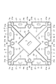
- FIG. 1 is a perspective view showing a part of a magnet type plate toy according to the embodiment in a cutaway manner.
- a magnetic plate toy 1 shown in FIG. 1 is an educational toy for developing children's creativity and imagination through play.
- FIG. 2 is a top view showing a state where the upper wall of the magnetic plate toy of FIG. 1 is removed.
- the magnetic plate toy 1 includes a plurality (here, eight) of first magnets 2, second magnets 3, and plate members 4.
- the first magnet 2 and the second magnet 3 have a columnar shape.
- the first magnet 2 and the second magnet 3 have a quadrangular prism shape with a square bottom surface, particularly a square column shape with a square bottom surface.
- the first magnet 2 and the second magnet 3 are made of the same material, for example.
- the first magnet 2 and the second magnet 3 are, for example, neodymium magnets.
- the first magnet 2 and the second magnet 3 have a magnetization direction orthogonal to the axial direction. That is, the first magnet 2 and the second magnet 3 are divided into two in a direction orthogonal to the axial direction.
- the first magnet 2 has an N pole portion disposed on one side in a direction orthogonal to the axial direction and an S pole portion disposed on the other side in a direction orthogonal to the axial direction.
- the dimension (volume) and magnetic force of the 2nd magnet 3 are larger than the dimension and magnetic force of the 1st magnet 2, for example.
- the approximate external dimensions of the first magnet 2 are, for example, 3 mm ⁇ 3 mm ⁇ 6 mm.
- the approximate external dimension of the second magnet 3 is, for example, 3 mm ⁇ 3 mm ⁇ 8 mm.
- the plate member 4 is a plate-like member having a uniform thickness.
- the plate member 4 has a polygonal shape such as a triangular shape or a rectangular shape as viewed from the thickness direction D1 of the plate member 4.
- the plate member 4 has a rectangular shape, particularly a square shape when viewed from the thickness direction D1.
- the plate member 4 has a plurality of (here, four) side portions 4a.
- Each side 4a is provided with a groove 4b having a U-shaped cross section extending along the thickness direction D1.
- the groove 4b is provided in the central portion in the length direction of the side portion 4a.
- the groove 4b may not be provided.
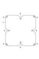
- FIG. 3 is a bottom view of the upper wall of the magnetic plate toy of FIG.
- the plate member 4 is hollow, and has a bottom member 5 and an upper wall 6.
- the bottom member 5 has a bottom wall 7 that faces the top wall 6, and four side walls 8 that connect the top wall 6 and the bottom wall 7.
- the top wall 6 and the bottom wall 7 have a square shape with a side of, for example, 75 mm.
- the four side walls 8 have a rectangular shape of, for example, 75 mm ⁇ 6.5 mm. That is, the thickness of the plate member 4 is, for example, 6.5 mm, and the plate member 4 has a square shape with one side of, for example, 75 mm as viewed from the thickness direction D1.
- the plate member 4 is made of plastic such as ABS resin (acrylonitrile-butadiene-styrene copolymer). Since the plate member 4 is made of plastic, it can be easily manufactured, for example, by injection molding. For example, by using plastics of various colors as the material of the plate member 4, the child's interest can be increased. By using transparent plastic as the material of the plate member 4, the inside of the assembled three-dimensional figure can be seen. Thereby, a child's interest can further be heightened.
- plastic such as ABS resin (acrylonitrile-butadiene-styrene copolymer). Since the plate member 4 is made of plastic, it can be easily manufactured, for example, by injection molding. For example, by using plastics of various colors as the material of the plate member 4, the child's interest can be increased. By using transparent plastic as the material of the plate member 4, the inside of the assembled three-dimensional figure can be seen. Thereby, a child's interest can further be heightened.
- the plate member 4 is formed by covering the opening of the bottom member 5 with the upper wall 6.
- the bottom member 5 and the upper wall 6 are assembled by fitting the cylindrical portions 7a provided at the four corners of the bottom wall 7 and the cylindrical portions 6a provided at the four corners of the upper wall 6 to each other. .
- a cylindrical portion 6a is provided inside the cylindrical portion 7a, and a metal eyelet 9 is provided inside the cylindrical portion 6a. Thereby, the bottom member 5 and the upper wall 6 are joined together.
- the bottom member 5 and the upper wall 6 are joined together by high frequency welding or the like.
- a plurality of ribs 11 to 13 are provided inside the bottom member 5.
- the plurality of ribs 11 to 13 are provided on the bottom wall 7.
- the plurality of ribs 11 to 13 extend along the thickness direction D1 of the plate member 4.
- the height of the plurality of ribs 11 to 13 (the length in the thickness direction D1) is equal to the distance between the upper wall 6 and the bottom wall 7.
- the tips of the plurality of ribs 11 to 13 are connected to the upper wall 6.
- the plurality of ribs 11 to 13 extend along the bottom wall 7.
- ribs 13 are provided inside the bottom member 5. Thereby, the strength of the plate member 4 is improved.
- a plurality of substantially cylindrical portions 14 are provided on the bottom wall 7.
- the plurality of substantially cylindrical portions 14 are cylindrical members provided with slits extending in the axial direction.
- the plurality of substantially cylindrical portions 14 have a C-shaped cross section.
- the plurality of substantially cylindrical portions 14 are arranged so that the slit faces the groove 4b.
- the plurality of substantially cylindrical portions 14 are fitted to the plurality of cylindrical portions 6 b provided on the upper wall 6.
- the substantially cylindrical portion 14 is disposed outside and the cylindrical portion 6b is disposed inside.
- the substantially cylindrical portion 14 and the cylindrical portion 6 b have a role of a guide that makes it easy to assemble the bottom member 5 and the upper wall 6.
- the strength of the plate member 4 is further improved by the substantially cylindrical portion 14 and the cylindrical portion 6b.
- the plate member 4 has a plurality of (eight in this case) first accommodation portions 21 and second accommodation portions 22 therein.
- the plurality of first accommodating portions 21 accommodates the plurality of first magnets 2 one by one.
- the plurality of first accommodating portions 21 are defined by the rib 11, the upper wall 6, the bottom wall 7, and the side wall 8.
- the plurality of first accommodating portions 21 are arranged apart from each other along the side portion 4 a of the plate member 4.
- a pair of first accommodating portions 21 are arranged along each side portion 4a.
- the 1st accommodating part 21 has the edge part 21a and the edge part 21b in the direction in alignment with the edge part 4a.
- the plurality of first accommodating portions 21 are arranged so that the end portions 21a or the end portions 21b are adjacent to each other in the pair of adjacent first accommodating portions 21.
- the end portions 21b face each other across the groove 4b.
- FIG. 4 is a partially enlarged view of FIG.
- the length L1 of the end 21a when viewed from the thickness direction D1 (see FIG. 1), the length L1 of the end 21a is equal to or longer than the length L2 of the first magnet 2 in the direction orthogonal to the axial direction. It is shorter than the length L3 of the first magnet 2 in the direction.
- the length L4 of the end portion 21b when viewed from the thickness direction D1, is not less than the length L2 and shorter than the length L3.
- the length L1 and the length L4 are equivalent, for example.
- the length L5 of the first housing part 21 in the direction orthogonal to the side part 4a (side part 4a provided with the first housing part 21) is longer than the length L3.
- the length L6 of the first accommodating portion 21 in the direction along the side portion 4a is, for example, longer than three times the length L3, longer than 1 ⁇ 4 of the length of the side portion 4a, and the length of the side portion 4a. Shorter than 1/3 of.
- the length L1 is 5 mm, for example.
- the length L2 is 3 mm, for example, and the length L3 is 6 mm, for example.
- the length L1 is 5 mm, for example.
- the length L5 is 9 mm, for example.
- the length L6 is, for example, 22 mm.
- the length of the first accommodating portion 21 in the thickness direction D1 (the interval between the upper wall 6 and the bottom wall 7) is shorter than the length L3. Therefore, in the 1st accommodating part 21, the axial direction of the 1st magnet 2 is orthogonal to the thickness direction D1, and does not follow the thickness direction D1.
- the length of the 1st accommodating part 21 in thickness direction D1 is 4.8 mm, for example.
- the plurality of first magnets 2 can move along the side portions 4a of the plate member 4, and can rotate around the rotation axis along the axial direction and the rotation axis along the thickness direction D1. Contained.
- the 1st accommodating part 21 is set to the magnitude
- the second housing portion 22 houses the second magnet 3.
- the second accommodating portion 22 is defined by the rib 12, the upper wall 6 (see FIG. 1), and the bottom wall 7.
- the second accommodating portion 22 is disposed away from the side portion 4 a and the plurality of first accommodating portions 21.
- the second accommodating portion 22 has a square shape with one side of, for example, 26 mm as viewed from the thickness direction D1 (see FIG. 1), and is disposed in the center portion of the plate member 4.
- Each corner portion of the second accommodating portion 22 is opposed to the central portion of each side portion 4a of the plate member 4 (see FIG. 1).
- Each corner portion of the second accommodating portion 22 faces the groove 4b with the substantially cylindrical portion 14 interposed therebetween.
- Each side portion of the second accommodating portion 22 is connected to the cylindrical portion 7 a by the rib 13.
- the 2nd magnet 3 is accommodated in the 2nd accommodating part 22 so that a movement in the direction orthogonal to thickness direction D1 is possible.
- the length of the second accommodating portion 22 in the thickness direction D1 (the interval between the upper wall 6 and the bottom wall 7) is shorter than the length of the second magnet 3 in the axial direction. Therefore, in the 2nd accommodating part 22, the axial direction of the 2nd magnet 3 is orthogonal to the thickness direction D1, and does not follow the thickness direction D1.
- the length of the 2nd accommodating part 22 in thickness direction D1 is equivalent to the length of the 1st accommodating part 21 in thickness direction D1, for example.
- the length of the 2nd accommodating part 22 in thickness direction D1 is 4.8 mm, for example.
- the second magnet 3 is accommodated in the second accommodating portion 22 so as to be rotatable around a rotation axis along the axial direction and a rotation axis along the thickness direction D1.
- the 2nd accommodating part 22 is set to the magnitude
- the first magnet 2 is accommodated in the first accommodating portion 21 so as to be movable along the side portion 4 a of the plate member 4. For this reason, it can be connected with other magnet type plate toys in the wide range in side 4a.
- the other magnetic plate toy can be moved (slid) along the side 4a while the other magnetic plate toy is connected to the side 4a of the magnetic plate toy 1.
- Other magnetic plate toys may have the same configuration as the magnetic plate toy 1, or may have a configuration different from the magnetic plate toy 1. As an example, it is assumed that other magnetic plate toys have the same configuration as the magnetic plate toy 1.
- the length L1 is not less than the length L2 and shorter than the length L3.
- the entire pair of end portions 2 a (the bottom surface portion of the first magnet 2) in the axial direction of the first magnet 2 can be disposed on the end portion 21 a of the first housing portion 21.
- the entire pair of end portions 2 b (side portions of the first magnet 2) in the direction orthogonal to the axial direction of the first magnet 2 cannot be disposed on the end portion 21 a of the first housing portion 21.
- the end 2a has a lower magnetic force than the end 2b.
- the first magnet 2 is accommodated in the first accommodating portion 21 so as to be rotatable not only around the rotation axis along the axial direction but also around the rotation axis along the thickness direction D1. For this reason, the magnetic plate toy 1 can be connected to other magnetic plate toys other than the side 4 a of the plate member 4. From the above, according to the magnetic plate toy 1, it is possible to enable a variety of connection methods with respect to other magnetic plate toys.
- the length L4 of the end 21b is equal to the length L1 of the end 21a. That is, the length L4 is not less than the length L2 and shorter than the length L3. For this reason, the entire end portion 2 a can be disposed on the end portion 21 b of the first housing portion 21. However, the entire end portion 2 b cannot be disposed on the end portion 21 b of the first housing portion 21. Thereby, the range which can move the 1st magnet 2 along the side part 4a can further be expanded, preventing the connection of the 1st magnets 2 between the 1st accommodating parts 21 adjacent to each other.
- the first magnet 2 has a quadrangular prism shape. For this reason, the 1st magnet 2 connects with another magnet type plate toy in a plane side part, ie, end 2b. Therefore, compared with the case where the 1st magnet 2 exhibits a column shape and it connects with another magnet type plate toy by a curved-surface side part, a connection force can be improved.
- the second magnet 3 is accommodated in the second accommodating portion 22 so as to be movable in a direction orthogonal to the thickness direction D1.
- the second accommodating portion 22 is disposed away from the side portion 4 a and the plurality of first accommodating portions 21.
- another magnetic plate toy can be connected to a wide range of the upper wall 6 and the bottom wall 7 of the magnetic plate toy 1.
- the other magnetic plate toy is moved along the upper wall 6 or the bottom wall 7 while the other magnetic plate toy is connected to the upper wall 6 or the bottom wall 7 of the magnetic plate toy 1 ( Slide).
- the top wall 6 and bottom wall 7 of the magnetic plate toy 1 may be connected to the top wall of another magnetic plate toy, the bottom wall may be connected, or the side wall may be connected. Also good.
- the second magnet 3 is accommodated in the second accommodating portion 22 so as to be rotatable not only about the rotation axis along the axial direction but also around the rotation axis along the thickness direction D1. Therefore, for example, another magnetic plate toy can be rotated in a state in which the side portion of the other magnetic plate toy is connected to the upper wall 6 or the bottom wall 7 of the magnetic plate toy 1. Therefore, it is possible to make the connection method more varied.
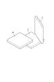
- FIG. 5 is a perspective view for explaining a connecting method of the magnetic plate toy.
- the illustration of the groove 4b is omitted.
- a plurality (three in this case) of magnetic plate toys 1 are connected to each other.
- the magnetic plate toy 1 not only the side portion 4 a but also arbitrary positions of the upper wall 6 and the bottom wall 7 can be connected to another magnetic plate toy 1.
- the magnetic plate toy 1 even when the magnet of another magnetic plate toy is fixed at a predetermined position of the plate member, the first magnet 2 or the second magnet 2 is matched to the direction of the magnet of the other magnetic plate toy. The magnet 3 rotates. Therefore, the magnetic plate toy 1 can be connected to other magnetic plate toys without repulsion.
- the magnet type plate toy 1 only needs to have at least two or more first magnets 2 and first accommodating portions 21.
- the magnetic plate toy 1 does not need to have the second accommodating portion 22.
- the number and size of the first housing part 21 and the second housing part 22 can be appropriately adjusted according to the shape of the plate member 4. It is sufficient that at least one of the length L1 and the length L4 is not less than the length L2 and shorter than the length L3. The other may be shorter than the length L2, or may be longer than the length L3.
- the first magnet 2 and the second magnet 3 may have a cylindrical shape, a triangular prism shape, or the like.
- the first magnet 2 and the second magnet 3 may be made of different materials.
- the size and magnetic force of the first magnet 2 may be equivalent to the size and magnetic force of the second magnet 3.
- the size and magnetic force of the first magnet 2 may be larger than the size and magnetic force of the second magnet 3.
- the second magnet 3 may not have a columnar shape.
- the second magnet 3 may have a disk shape, for example.
- the magnetization direction of the second magnet 3 may coincide with the axial direction.
Landscapes
- Toys (AREA)
Priority Applications (5)
| Application Number | Priority Date | Filing Date | Title |
|---|---|---|---|
| CN201880087378.6A CN111629799B (zh) | 2018-02-02 | 2018-07-13 | 磁铁式板玩具 |
| CA3089534A CA3089534A1 (en) | 2018-02-02 | 2018-07-13 | Magnet type plate toy |
| AU2018405668A AU2018405668A1 (en) | 2018-02-02 | 2018-07-13 | Magnet type plate toy |
| US16/481,491 US11077385B2 (en) | 2018-02-02 | 2018-07-13 | Magnetic plate toy |
| EP18904406.8A EP3747520A4 (en) | 2018-02-02 | 2018-07-13 | MAGNET TYPE PLATE TOY |
Applications Claiming Priority (2)
| Application Number | Priority Date | Filing Date | Title |
|---|---|---|---|
| JP2018-017469 | 2018-02-02 | ||
| JP2018017469A JP7048079B2 (ja) | 2018-02-02 | 2018-02-02 | 磁石式プレート玩具 |
Publications (1)
| Publication Number | Publication Date |
|---|---|
| WO2019150598A1 true WO2019150598A1 (ja) | 2019-08-08 |
Family
ID=67479678
Family Applications (1)
| Application Number | Title | Priority Date | Filing Date |
|---|---|---|---|
| PCT/JP2018/026568 Ceased WO2019150598A1 (ja) | 2018-02-02 | 2018-07-13 | 磁石式プレート玩具 |
Country Status (7)
| Country | Link |
|---|---|
| US (2) | US11077385B2 (enExample) |
| EP (1) | EP3747520A4 (enExample) |
| JP (1) | JP7048079B2 (enExample) |
| CN (1) | CN111629799B (enExample) |
| AU (1) | AU2018405668A1 (enExample) |
| CA (1) | CA3089534A1 (enExample) |
| WO (1) | WO2019150598A1 (enExample) |
Cited By (1)
| Publication number | Priority date | Publication date | Assignee | Title |
|---|---|---|---|---|
| EP3936208A1 (en) * | 2020-07-08 | 2022-01-12 | Yi-Ching Kuo | Magnetic attraction connection structure |
Families Citing this family (14)
| Publication number | Priority date | Publication date | Assignee | Title |
|---|---|---|---|---|
| JP7048079B2 (ja) * | 2018-02-02 | 2022-04-05 | ピープル株式会社 | 磁石式プレート玩具 |
| USD929505S1 (en) * | 2019-06-17 | 2021-08-31 | Howard Wang | Toy brick set |
| US11224821B2 (en) * | 2019-06-24 | 2022-01-18 | LaRose Industries, LLC | Shell-within-a-shell magnetic toy construction block |
| CN111370200A (zh) * | 2020-04-15 | 2020-07-03 | 杭州思创磁性器件有限公司 | 一种全维度自由吸合磁路结构 |
| US12377362B2 (en) * | 2021-01-22 | 2025-08-05 | Retrospective Goods, LLC | Magnetic construction tile set |
| USD928239S1 (en) * | 2021-01-26 | 2021-08-17 | Laltitude Llc | Toy brick set |
| US20220297021A1 (en) * | 2021-03-18 | 2022-09-22 | Dreambuilder Toy LLC | Magnetic Toy Device |
| US11857889B2 (en) * | 2021-07-09 | 2024-01-02 | Howard Wang | Spinning magnetic toy block |
| CN219681680U (zh) * | 2022-07-07 | 2023-09-15 | 浙江菲元科技有限公司 | 一种拼插动物积木玩具 |
| USD1026113S1 (en) * | 2023-04-14 | 2024-05-07 | Sheng Ying | Magnetic building tile |
| USD1008370S1 (en) * | 2023-06-20 | 2023-12-19 | Zewei Chen | Diamond block toy |
| CN221950571U (zh) * | 2023-09-13 | 2024-11-05 | 学习和成长玩具私人有限公司 | 一种带有装饰面板的磁力片游戏系统 |
| US12193568B1 (en) | 2024-05-23 | 2025-01-14 | Stephen F. McIrvin | Configurable magnetic dividers for a storage receptacle |
| USD1103296S1 (en) * | 2024-10-28 | 2025-11-25 | Jianan Huang | Toy track segment tile |
Citations (7)
| Publication number | Priority date | Publication date | Assignee | Title |
|---|---|---|---|---|
| JPH08257252A (ja) * | 1995-01-25 | 1996-10-08 | Sutatsufu:Kk | ブロック玩具 |
| WO2006095939A1 (en) * | 2005-03-11 | 2006-09-14 | Magnet4U Co., Ltd | Panel-type magnetic toys |
| US20100087119A1 (en) * | 2006-10-12 | 2010-04-08 | Claudio Vicentelli | Set of blocks with freely movable magnetic anchoring elements, for the construction of game assemblies |
| US20100120322A1 (en) * | 2006-10-12 | 2010-05-13 | Claudio Vicentelli | Set of blocks for construction game |
| JP3161698U (ja) | 2010-05-27 | 2010-08-05 | ニチレイマグネット株式会社 | 磁石式プレート玩具 |
| JP2013514128A (ja) * | 2009-12-18 | 2013-04-25 | オルダ・コリア・カンパニー・リミテッド | 磁石取付け用部品及び磁石玩具 |
| JP2016214533A (ja) * | 2015-05-20 | 2016-12-22 | ジムワールド インクGymworld Inc. | 組立玩具 |
Family Cites Families (14)
| Publication number | Priority date | Publication date | Assignee | Title |
|---|---|---|---|---|
| US3982334A (en) * | 1970-03-27 | 1976-09-28 | Thalatta, Inc. | Compartmentalized micromagnet display device |
| JPS5334747B2 (enExample) | 1973-07-13 | 1978-09-22 | ||
| JPH07101647B2 (ja) * | 1993-04-12 | 1995-11-01 | 株式会社マグエックス | 吸着体 |
| DE69509743T2 (de) | 1995-01-25 | 1999-09-16 | Stuff Co., Ltd. | Bauspielzeug |
| WO2006070741A1 (ja) | 2004-12-27 | 2006-07-06 | Ssd Company Limited | 釣り疑似体験装置および演出装置 |
| US7160170B2 (en) * | 2005-04-20 | 2007-01-09 | Magnet 4 U Co., Ltd. | Panel-type magnetic toys |
| WO2008142487A1 (en) * | 2007-05-22 | 2008-11-27 | Yipi Pte Ltd | Magnetic panel toys |
| US20090170396A1 (en) * | 2007-09-05 | 2009-07-02 | Mega Brands International S.A.R.L. | Portable magnetic toy construction kit |
| US8444449B2 (en) * | 2009-04-06 | 2013-05-21 | Duncan Bowes | Amusement apparatus and method featuring magnetic beads |
| EP2799121A4 (en) | 2011-12-28 | 2015-11-18 | Kajin Group Pte Ltd | MAGNETIC MOUNTED PARTS AND MAGNETIC TOY |
| JP2015037471A (ja) * | 2013-07-18 | 2015-02-26 | ジムワールド インクGymworld Inc. | 組立玩具 |
| JP6383649B2 (ja) * | 2014-11-26 | 2018-08-29 | ピープル株式会社 | 磁石式プレート玩具及びこれに用いるタイヤ部材 |
| CN206214780U (zh) * | 2016-07-19 | 2017-06-06 | 广州市掌芯计算机科技有限公司 | 磁性积木玩具 |
| JP7048079B2 (ja) * | 2018-02-02 | 2022-04-05 | ピープル株式会社 | 磁石式プレート玩具 |
-
2018
- 2018-02-02 JP JP2018017469A patent/JP7048079B2/ja not_active Expired - Fee Related
- 2018-07-13 EP EP18904406.8A patent/EP3747520A4/en not_active Withdrawn
- 2018-07-13 CA CA3089534A patent/CA3089534A1/en active Pending
- 2018-07-13 US US16/481,491 patent/US11077385B2/en not_active Expired - Fee Related
- 2018-07-13 AU AU2018405668A patent/AU2018405668A1/en not_active Abandoned
- 2018-07-13 WO PCT/JP2018/026568 patent/WO2019150598A1/ja not_active Ceased
- 2018-07-13 CN CN201880087378.6A patent/CN111629799B/zh not_active Expired - Fee Related
-
2021
- 2021-06-14 US US17/346,300 patent/US11376516B2/en active Active
Patent Citations (7)
| Publication number | Priority date | Publication date | Assignee | Title |
|---|---|---|---|---|
| JPH08257252A (ja) * | 1995-01-25 | 1996-10-08 | Sutatsufu:Kk | ブロック玩具 |
| WO2006095939A1 (en) * | 2005-03-11 | 2006-09-14 | Magnet4U Co., Ltd | Panel-type magnetic toys |
| US20100087119A1 (en) * | 2006-10-12 | 2010-04-08 | Claudio Vicentelli | Set of blocks with freely movable magnetic anchoring elements, for the construction of game assemblies |
| US20100120322A1 (en) * | 2006-10-12 | 2010-05-13 | Claudio Vicentelli | Set of blocks for construction game |
| JP2013514128A (ja) * | 2009-12-18 | 2013-04-25 | オルダ・コリア・カンパニー・リミテッド | 磁石取付け用部品及び磁石玩具 |
| JP3161698U (ja) | 2010-05-27 | 2010-08-05 | ニチレイマグネット株式会社 | 磁石式プレート玩具 |
| JP2016214533A (ja) * | 2015-05-20 | 2016-12-22 | ジムワールド インクGymworld Inc. | 組立玩具 |
Non-Patent Citations (1)
| Title |
|---|
| See also references of EP3747520A4 |
Cited By (2)
| Publication number | Priority date | Publication date | Assignee | Title |
|---|---|---|---|---|
| EP3936208A1 (en) * | 2020-07-08 | 2022-01-12 | Yi-Ching Kuo | Magnetic attraction connection structure |
| US11527344B2 (en) * | 2020-07-08 | 2022-12-13 | Yi-Ching Kuo | Magnetic attraction connection structure |
Also Published As
| Publication number | Publication date |
|---|---|
| US20200353375A1 (en) | 2020-11-12 |
| US11376516B2 (en) | 2022-07-05 |
| CN111629799A (zh) | 2020-09-04 |
| US11077385B2 (en) | 2021-08-03 |
| EP3747520A1 (en) | 2020-12-09 |
| CN111629799B (zh) | 2022-06-24 |
| JP2019130237A (ja) | 2019-08-08 |
| US20210299586A1 (en) | 2021-09-30 |
| EP3747520A4 (en) | 2021-11-17 |
| CA3089534A1 (en) | 2019-08-08 |
| AU2018405668A1 (en) | 2020-08-27 |
| JP7048079B2 (ja) | 2022-04-05 |
Similar Documents
| Publication | Publication Date | Title |
|---|---|---|
| WO2019150598A1 (ja) | 磁石式プレート玩具 | |
| US20120270464A1 (en) | Toy blocks for children | |
| US20220047960A1 (en) | Three-dimensional geometric art toys | |
| JPH08257252A (ja) | ブロック玩具 | |
| KR101245060B1 (ko) | 유아용 블록완구 | |
| KR20130034897A (ko) | 자석을 이용한 조립식 블럭 완구 | |
| KR101783296B1 (ko) | 조립식 완구 | |
| KR200250911Y1 (ko) | 영구자석의 자력을 이용한 블록 조립체 | |
| KR102018601B1 (ko) | 조립형 교구 블록 | |
| US11925876B2 (en) | Magnet-type plate toy | |
| KR101250530B1 (ko) | 블록교구 | |
| JP3222470U (ja) | ブロック玩具 | |
| KR101679366B1 (ko) | 다면체 블록 완구 | |
| KR200399428Y1 (ko) | 1면 다극 자석이 결합된 자석 완구 | |
| KR101682359B1 (ko) | 입체 자석블록 | |
| KR101927033B1 (ko) | 조립식 블록완구 세트 | |
| KR20130045988A (ko) | 유아용 블록완구 | |
| KR102835406B1 (ko) | 구형 자석을 이용한 큐브 | |
| JP3212952U (ja) | 組立式玩具 | |
| JP3229504U (ja) | ブロック玩具 | |
| KR101927035B1 (ko) | 조립식 블록완구 세트 | |
| KR20120019811A (ko) | 유아 학습용 자석블록 | |
| KR20190001186A (ko) | 조립식 블록완구 세트 | |
| KR100740408B1 (ko) | 학습용 조립블록 | |
| KR20190001581A (ko) | 조립식 블록완구 세트 |
Legal Events
| Date | Code | Title | Description |
|---|---|---|---|
| 121 | Ep: the epo has been informed by wipo that ep was designated in this application |
Ref document number: 18904406 Country of ref document: EP Kind code of ref document: A1 |
|
| ENP | Entry into the national phase |
Ref document number: 3089534 Country of ref document: CA |
|
| NENP | Non-entry into the national phase |
Ref country code: DE |
|
| ENP | Entry into the national phase |
Ref document number: 2018405668 Country of ref document: AU Date of ref document: 20180713 Kind code of ref document: A |
|
| ENP | Entry into the national phase |
Ref document number: 2018904406 Country of ref document: EP Effective date: 20200902 |