WO2019148403A1 - 非连续传输的方法和设备 - Google Patents
非连续传输的方法和设备 Download PDFInfo
- Publication number
- WO2019148403A1 WO2019148403A1 PCT/CN2018/074844 CN2018074844W WO2019148403A1 WO 2019148403 A1 WO2019148403 A1 WO 2019148403A1 CN 2018074844 W CN2018074844 W CN 2018074844W WO 2019148403 A1 WO2019148403 A1 WO 2019148403A1
- Authority
- WO
- WIPO (PCT)
- Prior art keywords
- drx
- pdcch
- timer
- terminal device
- occasion
- Prior art date
Links
Images


Classifications
-
- H—ELECTRICITY
- H04—ELECTRIC COMMUNICATION TECHNIQUE
- H04W—WIRELESS COMMUNICATION NETWORKS
- H04W52/00—Power management, e.g. TPC [Transmission Power Control], power saving or power classes
- H04W52/02—Power saving arrangements
- H04W52/0209—Power saving arrangements in terminal devices
- H04W52/0212—Power saving arrangements in terminal devices managed by the network, e.g. network or access point is master and terminal is slave
- H04W52/0216—Power saving arrangements in terminal devices managed by the network, e.g. network or access point is master and terminal is slave using a pre-established activity schedule, e.g. traffic indication frame
-
- H—ELECTRICITY
- H04—ELECTRIC COMMUNICATION TECHNIQUE
- H04W—WIRELESS COMMUNICATION NETWORKS
- H04W52/00—Power management, e.g. TPC [Transmission Power Control], power saving or power classes
- H04W52/02—Power saving arrangements
- H04W52/0209—Power saving arrangements in terminal devices
- H04W52/0225—Power saving arrangements in terminal devices using monitoring of external events, e.g. the presence of a signal
-
- H—ELECTRICITY
- H04—ELECTRIC COMMUNICATION TECHNIQUE
- H04W—WIRELESS COMMUNICATION NETWORKS
- H04W24/00—Supervisory, monitoring or testing arrangements
- H04W24/08—Testing, supervising or monitoring using real traffic
-
- H—ELECTRICITY
- H04—ELECTRIC COMMUNICATION TECHNIQUE
- H04W—WIRELESS COMMUNICATION NETWORKS
- H04W52/00—Power management, e.g. TPC [Transmission Power Control], power saving or power classes
- H04W52/02—Power saving arrangements
- H04W52/0209—Power saving arrangements in terminal devices
- H04W52/0225—Power saving arrangements in terminal devices using monitoring of external events, e.g. the presence of a signal
- H04W52/0229—Power saving arrangements in terminal devices using monitoring of external events, e.g. the presence of a signal where the received signal is a wanted signal
-
- H—ELECTRICITY
- H04—ELECTRIC COMMUNICATION TECHNIQUE
- H04W—WIRELESS COMMUNICATION NETWORKS
- H04W68/00—User notification, e.g. alerting and paging, for incoming communication, change of service or the like
- H04W68/02—Arrangements for increasing efficiency of notification or paging channel
-
- H—ELECTRICITY
- H04—ELECTRIC COMMUNICATION TECHNIQUE
- H04W—WIRELESS COMMUNICATION NETWORKS
- H04W72/00—Local resource management
- H04W72/04—Wireless resource allocation
- H04W72/044—Wireless resource allocation based on the type of the allocated resource
- H04W72/0446—Resources in time domain, e.g. slots or frames
-
- H—ELECTRICITY
- H04—ELECTRIC COMMUNICATION TECHNIQUE
- H04W—WIRELESS COMMUNICATION NETWORKS
- H04W72/00—Local resource management
- H04W72/20—Control channels or signalling for resource management
- H04W72/23—Control channels or signalling for resource management in the downlink direction of a wireless link, i.e. towards a terminal
-
- H—ELECTRICITY
- H04—ELECTRIC COMMUNICATION TECHNIQUE
- H04W—WIRELESS COMMUNICATION NETWORKS
- H04W76/00—Connection management
- H04W76/20—Manipulation of established connections
- H04W76/28—Discontinuous transmission [DTX]; Discontinuous reception [DRX]
-
- Y—GENERAL TAGGING OF NEW TECHNOLOGICAL DEVELOPMENTS; GENERAL TAGGING OF CROSS-SECTIONAL TECHNOLOGIES SPANNING OVER SEVERAL SECTIONS OF THE IPC; TECHNICAL SUBJECTS COVERED BY FORMER USPC CROSS-REFERENCE ART COLLECTIONS [XRACs] AND DIGESTS
- Y02—TECHNOLOGIES OR APPLICATIONS FOR MITIGATION OR ADAPTATION AGAINST CLIMATE CHANGE
- Y02D—CLIMATE CHANGE MITIGATION TECHNOLOGIES IN INFORMATION AND COMMUNICATION TECHNOLOGIES [ICT], I.E. INFORMATION AND COMMUNICATION TECHNOLOGIES AIMING AT THE REDUCTION OF THEIR OWN ENERGY USE
- Y02D30/00—Reducing energy consumption in communication networks
- Y02D30/70—Reducing energy consumption in communication networks in wireless communication networks
Definitions
- Embodiments of the present application relate to the field of communications, and more specifically, to a method and apparatus for Discontinuous Reception (DRX).
- DRX Discontinuous Reception
- the DRX mechanism was introduced for the consideration of power saving of terminal equipment.
- the network device can configure the terminal device to "wake up” at the time predicted by the network device, and listen to the downlink control channel when waking up, or configure the terminal device to "sleep" at the time predicted by the network device, and do not listen to the downlink control channel while sleeping. In this way, if the network device has data to transmit to the terminal device, the terminal device can be scheduled within the wake-up time of the terminal device, and the terminal device can reduce power consumption during the sleep time.
- the duration and location of the wake-up and sleep of the terminal device can be flexibly changed, and this change may affect the monitoring of the control channel by the terminal device. Therefore, in the 5G system, how to ensure that the terminal device effectively performs the downlink control channel monitoring becomes an urgent problem to be solved.
- the embodiment of the present application provides a method and device for discontinuous transmission, which can ensure that the terminal device effectively performs monitoring of the downlink control channel.
- a method for discontinuous transmission comprising: monitoring, by a terminal device, a physical downlink control channel PDCCH during a DRX activation period; wherein, if the DRX timer starts and/or times out within the PDCCH listening timing, The DRX activation period includes the PDCCH monitoring occasion, or the DRX activation period does not include the PDCCH monitoring occasion.
- the terminal device can be guaranteed to be more The monitoring of the downlink control channel is effectively performed.
- the PDCCH monitoring occasion includes one or more consecutive time domain symbols.
- the PDCCH monitoring occasion is configured for a network device.
- the DRX timer is any one of the following: a DRX duration timer, a DRX inactivity timer, a DRX uplink retransmission timer, a DRX downlink retransmission timer, and a competition. Solve the timer.
- the DRX timer starts and/or times out in the PDCCH monitoring occasion, including: a time when the DRX timer starts or times out, and is located in the PDCCH monitoring occasion except Any time other than the start time of the PDCCH listening opportunity and the end time of the PDCCH listening opportunity.
- the DRX timer starts and/or times out in the PDCCH listening occasion, including: a moment when the DRX timer starts, after a start time of the PDCCH monitoring occasion, and The time when the DRX timer expires is before the end time of the PDCCH listening occasion.
- the method further includes: if the terminal device monitors the PDCCH in the PDCCH monitoring occasion, the terminal device starts or restarts a DRX duration timer.
- a terminal device which can perform the operations of the terminal device in the above first aspect or any optional implementation manner of the first aspect.
- the terminal device may comprise an end in any of the possible implementations of the first aspect or the first aspect described above.
- a terminal device comprising: a processor, a transceiver, and a memory.
- the processor, the transceiver, and the memory communicate with each other through an internal connection path.
- the memory is for storing instructions for executing instructions stored by the memory.
- the processor executes the instruction stored by the memory, the executing causes the terminal device to perform the method of the first aspect or any possible implementation of the first aspect, or the execution causes the terminal device to implement the terminal provided by the second aspect device.
- a system chip comprising an input interface, an output interface, a processor, and a memory
- the processor is configured to execute an instruction stored by the memory, and when the instruction is executed, the processor can implement the foregoing The method of any of the first aspect or any of the possible implementations of the first aspect.
- a computer program product comprising instructions which, when run on a computer, cause the computer to perform the method of any of the first aspect or the first aspect of the first aspect.
- FIG. 1 is a schematic diagram of a wireless communication system in accordance with an embodiment of the present application.
- Figure 2 is a schematic diagram of the DRX cycle.
- FIG. 3 is a schematic flowchart of a method for discontinuous transmission according to an embodiment of the present application.
- FIG. 4 is a schematic block diagram of a DRX activation period of an embodiment of the present application.
- FIG. 5 is a schematic block diagram of a DRX activation period of an embodiment of the present application.
- FIG. 6 is a schematic block diagram of a DRX activation period of an embodiment of the present application.
- FIG. 7 is a schematic block diagram of a DRX activation period of an embodiment of the present application.
- FIG. 8 is a schematic block diagram of a DRX activation period of an embodiment of the present application.
- FIG. 9 is a schematic block diagram of a DRX activation period of an embodiment of the present application.
- FIG. 10 is a schematic block diagram of a terminal device according to an embodiment of the present application.
- FIG. 11 is a schematic structural diagram of a terminal device according to an embodiment of the present application.
- FIG. 12 is a schematic structural diagram of a system chip according to an embodiment of the present application.
- GSM Global System of Mobile communication
- CDMA Code Division Multiple Access
- WCDMA Wideband Code Division Multiple Access
- GPRS General Packet Radio Service
- LTE Long Term Evolution
- FDD Frequency Division Duplex
- TDD Time Division Duplex
- UPD Universal Mobile Telecommunication System
- WiMAX Worldwide Interoperability for Microwave Access
- FIG. 1 shows a wireless communication system 100 to which an embodiment of the present application is applied.
- the wireless communication system 100 can include a network device 110.
- Network device 100 can be a device that communicates with a terminal device.
- Network device 100 may provide communication coverage for a particular geographic area and may communicate with terminal devices (e.g., UEs) located within the coverage area.
- the network device 100 may be a base station (Base Transceiver Station, BTS) in a GSM system or a CDMA system, or may be a base station (NodeB, NB) in a WCDMA system, or may be an evolved base station in an LTE system.
- BTS Base Transceiver Station
- NodeB NodeB
- the network device can be a relay station, an access point, an in-vehicle device, a wearable device, and a future A network side device in a 5G network or a network device in a publicly available Public Land Mobile Network (PLMN) in the future.
- PLMN Public Land Mobile Network
- the wireless communication system 100 also includes at least one terminal device 120 located within the coverage of the network device 110.
- Terminal device 120 can be mobile or fixed.
- the terminal device 120 may refer to an access terminal, a user equipment (User Equipment, UE), a subscriber unit, a subscriber station, a mobile station, a mobile station, a remote station, a remote terminal, a mobile device, a user terminal, a terminal, and a wireless communication.
- the access terminal may be a cellular phone, a cordless phone, a Session Initiation Protocol (SIP) phone, a Wireless Local Loop (WLL) station, a Personal Digital Assistant (PDA), with wireless communication.
- D2D device to device communication
- D2D device to device
- the 5G system or network may also be referred to as a New Radio (NR) system or network.
- NR New Radio
- FIG. 1 exemplarily shows one network device and two terminal devices.
- the wireless communication system 100 may include a plurality of network devices and may include other numbers of terminal devices within the coverage of each network device. The application embodiment does not limit this.
- the wireless communication system 100 may further include other network entities, such as a network controller, a mobility management entity, and the like.
- network entities such as a network controller, a mobility management entity, and the like.
- a media access control (MAC) entity is configured by a Radio Resource Control (RRC) to configure a DRX function for controlling a terminal device to listen to a physical downlink control channel (Physical Downlink Control Channel). , PDCCH) behavior.
- RRC Radio Resource Control
- PDCCH Physical Downlink Control Channel
- the MAC entity can continuously monitor the PDCCH during the On Duration, and during the sleep period (Opportunity for DRX). The PDCCH is not monitored, thereby reducing the power consumption of the terminal device.
- the network device can configure a set of DRX parameters for the MAC entity through RRC signaling, for example, configuring a series of DRX timers to manage the wakeup and sleep states of the terminal device. According to the values of these parameters, the DRX cycle as shown in Fig. 2 can be obtained.
- the time position of the wake-up and sleep state of the terminal device can be flexibly changed, and this change may affect the monitoring of the control channel by the terminal device.
- the DRX timer starts and/or times out in the PDCCH listening occasion, since the DRX activation period of the terminal device includes the PDCCH monitoring occasion, or the DRX activation period does not include the PDCCH monitoring occasion, Thereby, it is possible to ensure that the terminal device performs the monitoring of the downlink control channel more efficiently.
- the monitoring in the embodiment of the present application may also be referred to as listening, detecting, monitoring, detecting, and the like.
- the activation time (Active Time) of the terminal device may also be referred to as an activation time, an awake period, a wake-up time, and the like.
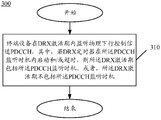
- FIG. 3 is a schematic flowchart of a method for discontinuous transmission according to an embodiment of the present application.
- the terminal device shown in FIG. 3 may be, for example, the terminal device 120 shown in FIG. 1.
- the method for discontinuous transmission includes:
- the terminal device listens to the physical downlink control channel PDCCH during the DRX activation period.
- the DRX activation period includes the PDCCH monitoring occasion, or the DRX activation period does not include the PDCCH monitoring occasion.
- the DRX activation period of the terminal device does not include the PDCCH monitoring occasion, or the DRX activation period includes the PDCCH monitoring occasion, thereby causing the terminal device to The listening process of the PDCCH is not affected.
- the PDCCH monitoring occasion may include one or more consecutive time domain symbols.
- the PDCCH monitoring occasion is configured for the network device.
- the network device can send configuration information to the terminal device to indicate the time domain location of the PDCCH.
- the DRX timer can be any one of the following timers:
- DRX uplink retransmission timer (drx-RetransmissionTimerUL);
- DRX-RetransmissionTimerDL DRX downlink retransmission timer
- the competition resolution timer (mac-ContentionResolutionTimer).
- the DRX timer starts and/or times out in the PDCCH monitoring occasion, and includes: a time when the DRX timer starts or times out, and is located at the start of the PDCCH monitoring occasion in the PDCCH monitoring occasion. The time and any time other than the end time of the PDCCH listening opportunity.
- the time when the DRX timer starts or times out is located after the start time of the PDCCH listening occasion and before the end time of the PDCCH listening occasion.
- the DRX timer starts and/or times out in the PDCCH listening occasion, including: the time when the DRX timer starts is located after the start time of the PDCCH monitoring occasion, and the DRX timer expires. The time is before the end time of the PDCCH listening opportunity.
- the method may further include: if the terminal device monitors the PDCCH in the PDCCH monitoring occasion, the terminal device starts or restarts the DRX duration timer.
- the DRX timer starts and/or times out within the PDCCH listening timing, it may affect the process of monitoring the PDCCH by the terminal device. For example, if the drx-inactivityTimer times out within one PDCCH listening timing of the terminal device, the terminal device stops monitoring the PDCCH, thereby affecting the process of the terminal device monitoring the PDCCH.
- the terminal device since it is determined that the DRX activation period includes the PDCCH monitoring occasion, or the DRX activation period does not include the PDCCH monitoring occasion, the terminal device can ensure that the downlink control channel is monitored more effectively.
- the terminal device still monitors the PDCCH within the PDCCH listening occasion, thereby avoiding the impact on the PDCCH monitoring process.
- the DRX activation period includes the PDCCH listening timing. It is assumed that the network device configures the PDCCH listening occasion to be the first three time domain symbols of one subframe. If a DRX timer is started in the second time domain symbol of the subframe, the terminal device needs to perform PDCCH monitoring in the first three time domain symbols until the DRX timer expires.
- the DRX activation period does not include the PDCCH listening occasion. It is assumed that the network device configures the PDCCH listening occasion as the first three time domain symbols of one subframe. If a DRX timer is started in the second time domain symbol of the subframe, the terminal device needs to perform PDCCH listening from the fourth time domain symbol until the DRX timer expires.
- the DRX activation period includes the PDCCH listening timing. It is assumed that the network device configures the PDCCH listening occasion to be the first three time domain symbols of one subframe. If a DRX timer times out in the second time domain symbol of the subframe, the terminal device needs to continue to perform PDCCH monitoring in the three time domain symbols.
- the DRX activation period does not include the PDCCH listening occasion. It is assumed that the network device configures the PDCCH listening occasion to be the first three time domain symbols of one subframe. If a DRX timer times out in the second time domain symbol of the subframe, the terminal device stops monitoring the PDCCH on the previous symbol of the three time domain symbols, that is, the terminal device does not The PDCCH is monitored on the time domain symbol.
- the DRX activation period includes the PDCCH listening timing. It is assumed that the network device configures the PDCCH listening occasion to be the first three time domain symbols of one subframe. If a DRX timer is started in the first time domain symbol of the subframe and times out in the third time domain symbol, the terminal device performs PDCCH monitoring in the three time domain symbols.
- the DRX activation period does not include the PDCCH listening occasion. It is assumed that the network device configures the PDCCH listening occasion to be the first three time domain symbols of one subframe. If a DRX timer is started in the first time domain symbol of the subframe and times out in the third time domain symbol, the terminal device may not have a DRX activation period, ie the terminal device will not be in these three times. The PDCCH is monitored on the domain symbol.
- the terminal device may restart the DRX duration timer, and at this time, the terminal device may perform PDCCH monitoring time. Will be extended.
- FIG. 10 is a schematic block diagram of a terminal device 1000 according to an embodiment of the present application.
- the terminal device 1000 includes a listening unit 1010.
- the monitoring unit 1010 is configured to: monitor the physical downlink control channel PDCCH during the DRX activation period.
- the DRX activation period includes the PDCCH monitoring occasion, or the DRX activation period does not include the PDCCH monitoring occasion.
- the terminal device can be guaranteed to be more The monitoring of the downlink control channel is effectively performed.
- the PDCCH snooping opportunity includes one or more consecutive time domain symbols.
- the PDCCH monitoring occasion is configured for a network device.
- the DRX timer is any one of the following: a DRX duration timer, a DRX inactivity timer, a DRX uplink retransmission timer, a DRX downlink retransmission timer, and a contention resolution timer.
- the DRX timer starts and/or times out in the PDCCH listening occasion, and includes: a time when the DRX timer starts or times out, and is located in the PDCCH monitoring occasion except the PDCCH monitoring occasion Any time other than the start time and the end time of the PDCCH listening opportunity.
- the DRX timer starts and/or times out in the PDCCH monitoring occasion, where: the time when the DRX timer is started is located after a start time of the PDCCH monitoring occasion, and the DRX timer The timeout time is before the end time of the PDCCH listening occasion.
- the terminal device further includes a processing unit, where the processing unit is configured to: if the monitoring unit 1010 monitors the PDCCH in the PDCCH monitoring occasion, start or restart a DRX duration timer.
- terminal device 1100 can perform the corresponding operations performed by the terminal device in the foregoing method 300, and details are not described herein for brevity.
- FIG. 11 is a schematic structural diagram of a terminal device 1100 according to an embodiment of the present application.
- the terminal device includes a processor 1110, a transceiver 1120, and a memory 1130, wherein the processor 1110, the transceiver 1120, and the memory 1130 communicate with each other through an internal connection path.
- the memory 1130 is configured to store instructions
- the processor 1110 is configured to execute instructions stored by the memory 1130 to control the transceiver 1120 to receive signals or send signals.
- the processor 1110 can call the program code stored in the memory 1130 to perform the corresponding operations performed by the terminal device in the method 300.
- the processor 1110 can call the program code stored in the memory 1130 to perform the corresponding operations performed by the terminal device in the method 300.
- the processor of the embodiment of the present application may be an integrated circuit chip with signal processing capability.
- each step of the foregoing method embodiment may be completed by an integrated logic circuit of hardware in a processor or an instruction in a form of software.
- the processor may be a general-purpose processor, a digital signal processor (DSP), an application specific integrated circuit (ASIC), a Field Programmable Gate Array (FPGA), or the like. Programming logic devices, discrete gates or transistor logic devices, discrete hardware components.
- the methods, steps, and logical block diagrams disclosed in the embodiments of the present application can be implemented or executed.
- the general purpose processor may be a microprocessor or the processor or any conventional processor or the like.
- the steps of the method disclosed in the embodiments of the present application may be directly implemented by the hardware decoding processor, or may be performed by a combination of hardware and software modules in the decoding processor.
- the software module can be located in a conventional storage medium such as random access memory, flash memory, read only memory, programmable read only memory or electrically erasable programmable memory, registers, and the like.
- the storage medium is located in the memory, and the processor reads the information in the memory and combines the hardware to complete the steps of the above method.
- the memory in the embodiments of the present application may be a volatile memory or a non-volatile memory, or may include both volatile and non-volatile memory.
- the non-volatile memory may be a read-only memory (ROM), a programmable read only memory (PROM), an erasable programmable read only memory (Erasable PROM, EPROM), or an electric Erase programmable read only memory (EEPROM) or flash memory.
- the volatile memory can be a Random Access Memory (RAM) that acts as an external cache.
- RAM Random Access Memory
- many forms of RAM are available, such as static random access memory (SRAM), dynamic random access memory (DRAM), synchronous dynamic random access memory (Synchronous DRAM).
- SDRAM Double Data Rate SDRAM
- DDR SDRAM Double Data Rate SDRAM
- ESDRAM Enhanced Synchronous Dynamic Random Access Memory
- SLDRAM Synchronous Connection Dynamic Random Access Memory
- DR RAM direct memory bus random access memory
- FIG. 12 is a schematic structural diagram of a system chip according to an embodiment of the present application.
- the system chip 1200 of FIG. 12 includes an input interface 1201, an output interface 1202, at least one processor 1203, and a memory 1204.
- the input interface 1201, the output interface 1202, the processor 1203, and the memory 1204 are interconnected by an internal connection path.
- the processor 1203 is configured to execute code in the memory 1204.
- the processor 1203 may implement a corresponding operation performed by the terminal device in the method 300. For the sake of brevity, it will not be repeated here.
- the disclosed systems, devices, and methods may be implemented in other manners.
- the device embodiments described above are merely illustrative.
- the division of the unit is only a logical function division.
- there may be another division manner for example, multiple units or components may be combined or may be Integrate into another system, or some features can be ignored or not executed.
- the mutual coupling or direct coupling or communication connection shown or discussed may be an indirect coupling or communication connection through some interface, device or unit, and may be in an electrical, mechanical or other form.
- the units described as separate components may or may not be physically separated, and the components displayed as units may or may not be physical units, that is, may be located in one place, or may be distributed to multiple network units. Some or all of the units may be selected according to actual needs to achieve the purpose of the solution of the embodiment.
- each functional unit in each embodiment of the present application may be integrated into one monitoring unit, or each unit may exist physically separately, or two or more units may be integrated into one unit.
- the functions may be stored in a computer readable storage medium if implemented in the form of a software functional unit and sold or used as a standalone product.
- the technical solution of the present application which is essential or contributes to the prior art, or a part of the technical solution, may be embodied in the form of a software product, which is stored in a storage medium, including
- the instructions are used to cause a computer device (which may be a personal computer, server, or network device, etc.) to perform all or part of the steps of the methods described in various embodiments of the present application.
- the foregoing storage medium includes: a U disk, a mobile hard disk, a read-only memory (ROM), a random access memory (RAM), a magnetic disk, or an optical disk, and the like, which can store program codes. .
Abstract
Description
Claims (14)
- 一种非连续传输DRX的方法,其特征在于,包括:终端设备在DRX激活期内监听物理下行控制信道PDCCH;其中,若DRX定时器在所述PDCCH监听时机内启动和/或超时,则所述DRX激活期包括所述PDCCH监听时机,或者,所述DRX激活期不包括所述PDCCH监听时机。
- 根据权利要求1所述的方法,其特征在于,所述PDCCH监听时机包括一个或多个连续的时域符号。
- 根据权利要求1或2所述的方法,所述PDCCH监听时机为网络设备配置的。
- 根据权利要求1至3中任一项所述的方法,其特征在于,所述DRX定时器为以下定时器中的任意一种:DRX持续时间定时器、DRX静止定时器、DRX上行重传定时器、DRX下行重传定时器和竞争解决定时器。
- 根据权利要求1至4中任一项所述的方法,其特征在于,所述DRX定时器在所述PDCCH监听时机内启动和/或超时,包括:所述DRX定时器启动或超时的时刻,位于所述PDCCH监听时机中除所述PDCCH监听时机的起始时刻和所述PDCCH监听时机的结束时刻之外的其他任何时刻。
- 根据权利要求1至4中任一项所述的方法,其特征在于,所述DRX定时器在所述PDCCH监听时机内启动和/或超时,包括:所述DRX定时器启动的时刻位于所述PDCCH监听时机的起始时刻之后,且所述DRX定时器超时的时刻位于所述PDCCH监听时机的结束时刻之前。
- 根据权利要求1至6中任一项所述的方法,其特征在于,所述方法还包括:若所述终端设备在所述PDCCH监听时机中监听到PDCCH,则所述终端设备启动或重启DRX持续时间定时器。
- 一种终端设备,其特征在于,所述终端设备包括监听单元,用于:在DRX激活期内监听物理下行控制信道PDCCH;其中,若DRX定时器在所述PDCCH监听时机内启动和/或超时,则所 述DRX激活期包括所述PDCCH监听时机,或者,所述DRX激活期不包括所述PDCCH监听时机。
- 根据权利要求8所述的终端设备,其特征在于,所述PDCCH监听时机包括一个或多个连续的时域符号。
- 根据权利要求8或9所述的终端设备,所述PDCCH监听时机为网络设备配置的。
- 根据权利要求8至10中任一项所述的终端设备,其特征在于,所述DRX定时器为以下定时器中的任意一种:DRX持续时间定时器、DRX静止定时器、DRX上行重传定时器、DRX下行重传定时器和竞争解决定时器。
- 根据权利要求8至11中任一项所述的终端设备,其特征在于,所述DRX定时器在所述PDCCH监听时机内启动和/或超时,包括:所述DRX定时器启动或超时的时刻,位于所述PDCCH监听时机中除所述PDCCH监听时机的起始时刻和所述PDCCH监听时机的结束时刻之外的其他任何时刻。
- 根据权利要求8至12中任一项所述的终端设备,其特征在于,所述DRX定时器在所述PDCCH监听时机内启动和/或超时,包括:所述DRX定时器启动的时刻位于所述PDCCH监听时机的起始时刻之后,且所述DRX定时器超时的时刻位于所述PDCCH监听时机的结束时刻之前。
- 根据权利要求8至13中任一项所述的终端设备,其特征在于,所述终端设备还包括处理单元,所述处理单元用于:若所述监听单元在所述PDCCH监听时机中监听到所述PDCCH,则启动或重启DRX持续时间定时器。
Priority Applications (10)
| Application Number | Priority Date | Filing Date | Title |
|---|---|---|---|
| PCT/CN2018/074844 WO2019148403A1 (zh) | 2018-01-31 | 2018-01-31 | 非连续传输的方法和设备 |
| SG11202007186SA SG11202007186SA (en) | 2018-01-31 | 2018-01-31 | Method and device for discontinuous transmission |
| AU2018405905A AU2018405905B2 (en) | 2018-01-31 | 2018-01-31 | Method and device for discontinuous transmission |
| CN202010595493.3A CN111757442A (zh) | 2018-01-31 | 2018-01-31 | 非连续传输的方法和设备 |
| CN201880067689.6A CN111264077A (zh) | 2018-01-31 | 2018-01-31 | 非连续传输的方法和设备 |
| EP18903421.8A EP3735046A4 (en) | 2018-01-31 | 2018-01-31 | METHOD AND DEVICE FOR DISCONTINUOUS TRANSMISSION |
| JP2020540774A JP7027561B2 (ja) | 2018-01-31 | 2018-01-31 | 間欠伝送の方法と装置 |
| KR1020207023792A KR102339953B1 (ko) | 2018-01-31 | 2018-01-31 | 불연속 전송의 방법과 장치 |
| MX2020007963A MX2020007963A (es) | 2018-01-31 | 2018-01-31 | Metodo y dispositivo para transmision discontinua. |
| US16/929,277 US11641691B2 (en) | 2018-01-31 | 2020-07-15 | Method and device for discontinuous transmission |
Applications Claiming Priority (1)
| Application Number | Priority Date | Filing Date | Title |
|---|---|---|---|
| PCT/CN2018/074844 WO2019148403A1 (zh) | 2018-01-31 | 2018-01-31 | 非连续传输的方法和设备 |
Related Child Applications (1)
| Application Number | Title | Priority Date | Filing Date |
|---|---|---|---|
| US16/929,277 Continuation US11641691B2 (en) | 2018-01-31 | 2020-07-15 | Method and device for discontinuous transmission |
Publications (1)
| Publication Number | Publication Date |
|---|---|
| WO2019148403A1 true WO2019148403A1 (zh) | 2019-08-08 |
Family
ID=67479953
Family Applications (1)
| Application Number | Title | Priority Date | Filing Date |
|---|---|---|---|
| PCT/CN2018/074844 WO2019148403A1 (zh) | 2018-01-31 | 2018-01-31 | 非连续传输的方法和设备 |
Country Status (9)
| Country | Link |
|---|---|
| US (1) | US11641691B2 (zh) |
| EP (1) | EP3735046A4 (zh) |
| JP (1) | JP7027561B2 (zh) |
| KR (1) | KR102339953B1 (zh) |
| CN (2) | CN111264077A (zh) |
| AU (1) | AU2018405905B2 (zh) |
| MX (1) | MX2020007963A (zh) |
| SG (1) | SG11202007186SA (zh) |
| WO (1) | WO2019148403A1 (zh) |
Cited By (1)
| Publication number | Priority date | Publication date | Assignee | Title |
|---|---|---|---|---|
| WO2021031045A1 (zh) * | 2019-08-16 | 2021-02-25 | 华为技术有限公司 | 一种通信方法及装置 |
Citations (3)
| Publication number | Priority date | Publication date | Assignee | Title |
|---|---|---|---|---|
| CN102548013A (zh) * | 2010-12-24 | 2012-07-04 | 中兴通讯股份有限公司 | 多种无线电技术在终端共存时的时分复用通信方法和系统 |
| CN107257564A (zh) * | 2017-07-18 | 2017-10-17 | 京信通信系统(中国)有限公司 | 一种调度终端的方法及网络设备 |
| US20170339682A1 (en) * | 2016-05-23 | 2017-11-23 | Lg Electronics Inc. | Method and user equipment for receiving downlink control information |
Family Cites Families (11)
| Publication number | Priority date | Publication date | Assignee | Title |
|---|---|---|---|---|
| US8488521B2 (en) * | 2008-03-14 | 2013-07-16 | Interdigital Patent Holdings, Inc. | Behavior for wireless transmit/receive unit and MAC control elements for LTE DRX operations |
| BRPI1013144B1 (pt) * | 2009-06-15 | 2021-03-02 | Guangdong Oppo Mobile Telecommunications Corp., Ltd | método e sistema para a operação de recepção descontínua para agregação de portadora avançada de evolução de longo prazo |
| KR101664279B1 (ko) * | 2010-02-16 | 2016-10-12 | 삼성전자주식회사 | 무선 통신 시스템에서 불연속 수신을 위한 제어 방법 및 장치 |
| CN102421148B (zh) * | 2010-09-28 | 2016-03-30 | 华为技术有限公司 | 一种控制多种通信系统实现通信的方法和用户设备 |
| CN102256321A (zh) * | 2011-07-14 | 2011-11-23 | 新邮通信设备有限公司 | 控制非连续接收下终端小区切换的方法和系统 |
| US8781502B1 (en) * | 2013-02-01 | 2014-07-15 | Swirl Networks, Inc. | Systems and methods for display of supplemental content responsive to location |
| CN106034318B (zh) * | 2015-03-16 | 2019-10-29 | 中国移动通信集团公司 | 一种非连续接收的控制方法和装置 |
| JP6813481B2 (ja) * | 2015-05-15 | 2021-01-13 | 京セラ株式会社 | 無線端末及び基地局 |
| WO2017078465A1 (en) * | 2015-11-04 | 2017-05-11 | Lg Electronics Inc. | Method and apparatus for handling overlap of different channels in wireless communication system |
| CN106899941B (zh) * | 2015-12-18 | 2020-08-07 | 普天信息技术有限公司 | 一种集群通信系统中非连续监听控制信道的方法和装置 |
| CN111183606B (zh) * | 2017-08-10 | 2024-04-16 | 交互数字专利控股公司 | 用于nr的增强型已连接模式drx过程 |
-
2018
- 2018-01-31 CN CN201880067689.6A patent/CN111264077A/zh active Pending
- 2018-01-31 MX MX2020007963A patent/MX2020007963A/es unknown
- 2018-01-31 CN CN202010595493.3A patent/CN111757442A/zh active Pending
- 2018-01-31 AU AU2018405905A patent/AU2018405905B2/en active Active
- 2018-01-31 KR KR1020207023792A patent/KR102339953B1/ko active IP Right Grant
- 2018-01-31 SG SG11202007186SA patent/SG11202007186SA/en unknown
- 2018-01-31 EP EP18903421.8A patent/EP3735046A4/en active Pending
- 2018-01-31 JP JP2020540774A patent/JP7027561B2/ja active Active
- 2018-01-31 WO PCT/CN2018/074844 patent/WO2019148403A1/zh unknown
-
2020
- 2020-07-15 US US16/929,277 patent/US11641691B2/en active Active
Patent Citations (3)
| Publication number | Priority date | Publication date | Assignee | Title |
|---|---|---|---|---|
| CN102548013A (zh) * | 2010-12-24 | 2012-07-04 | 中兴通讯股份有限公司 | 多种无线电技术在终端共存时的时分复用通信方法和系统 |
| US20170339682A1 (en) * | 2016-05-23 | 2017-11-23 | Lg Electronics Inc. | Method and user equipment for receiving downlink control information |
| CN107257564A (zh) * | 2017-07-18 | 2017-10-17 | 京信通信系统(中国)有限公司 | 一种调度终端的方法及网络设备 |
Non-Patent Citations (2)
| Title |
|---|
| See also references of EP3735046A4 * |
| YANG JUN ET AL.: "Introduction on principle of and optimization of LTE DRX", CHINA NEW TELECOMMUNICATIONS: CNT, no. 13, 5 July 2015 (2015-07-05), CN, pages 20 - 22, XP009522219, ISSN: 1673-4866 * |
Cited By (1)
| Publication number | Priority date | Publication date | Assignee | Title |
|---|---|---|---|---|
| WO2021031045A1 (zh) * | 2019-08-16 | 2021-02-25 | 华为技术有限公司 | 一种通信方法及装置 |
Also Published As
| Publication number | Publication date |
|---|---|
| AU2018405905B2 (en) | 2021-07-29 |
| KR20200110692A (ko) | 2020-09-24 |
| JP7027561B2 (ja) | 2022-03-01 |
| AU2018405905A1 (en) | 2020-08-20 |
| CN111264077A (zh) | 2020-06-09 |
| EP3735046A1 (en) | 2020-11-04 |
| SG11202007186SA (en) | 2020-08-28 |
| EP3735046A4 (en) | 2021-01-20 |
| KR102339953B1 (ko) | 2021-12-16 |
| JP2021511749A (ja) | 2021-05-06 |
| MX2020007963A (es) | 2020-09-24 |
| CN111757442A (zh) | 2020-10-09 |
| US11641691B2 (en) | 2023-05-02 |
| US20200344840A1 (en) | 2020-10-29 |
Similar Documents
| Publication | Publication Date | Title |
|---|---|---|
| EP3141075B1 (en) | Methods and apparatuses for indicating and adapting the activity state of a wireless device having device-to-device communication capabilities | |
| WO2021004119A1 (zh) | 唤醒方法及装置、存储介质、终端 | |
| TWI812621B (zh) | 非連續接收的方法、終端設備和網絡設備 | |
| WO2021082012A1 (zh) | 用于确定非连续接收持续定时器的启动状态的方法及设备 | |
| WO2020048457A1 (zh) | 一种通信方法及设备 | |
| US20210014786A1 (en) | Signal transmission method and device | |
| WO2021120013A1 (zh) | 监听唤醒信号的方法、终端设备和网络设备 | |
| US20230284138A1 (en) | Wireless communication method and device | |
| WO2020215332A1 (zh) | 非连续接收的方法和设备 | |
| JP2021510014A (ja) | Pdcchをモニターするための方法及び端末機器 | |
| WO2019183965A1 (zh) | 信号传输的方法和设备 | |
| WO2019037127A1 (zh) | 通信方法、终端设备和网络设备 | |
| WO2021004111A1 (zh) | 进入睡眠的方法及装置、存储介质、用户设备 | |
| TW201826862A (zh) | 用於非連續接收的訊號傳輸方法、終端設備和網路設備 | |
| CN110769381B (zh) | 一种drx实现和配置方法及装置 | |
| WO2020057395A1 (zh) | 通信方法与设备 | |
| US11641691B2 (en) | Method and device for discontinuous transmission | |
| WO2020164143A1 (zh) | 非连续接收的方法、终端设备和网络设备 | |
| WO2019153262A1 (zh) | 非连续接收的方法和设备 | |
| TWI839370B (zh) | 一種通道監聽方法及裝置、終端設備、網路設備 |
Legal Events
| Date | Code | Title | Description |
|---|---|---|---|
| 121 | Ep: the epo has been informed by wipo that ep was designated in this application |
Ref document number: 18903421 Country of ref document: EP Kind code of ref document: A1 |
|
| ENP | Entry into the national phase |
Ref document number: 2020540774 Country of ref document: JP Kind code of ref document: A |
|
| NENP | Non-entry into the national phase |
Ref country code: DE |
|
| ENP | Entry into the national phase |
Ref document number: 2018903421 Country of ref document: EP Effective date: 20200730 |
|
| ENP | Entry into the national phase |
Ref document number: 20207023792 Country of ref document: KR Kind code of ref document: A |
|
| ENP | Entry into the national phase |
Ref document number: 2018405905 Country of ref document: AU Date of ref document: 20180131 Kind code of ref document: A |