WO2019146210A1 - 熱電発電装置 - Google Patents
熱電発電装置 Download PDFInfo
- Publication number
- WO2019146210A1 WO2019146210A1 PCT/JP2018/041121 JP2018041121W WO2019146210A1 WO 2019146210 A1 WO2019146210 A1 WO 2019146210A1 JP 2018041121 W JP2018041121 W JP 2018041121W WO 2019146210 A1 WO2019146210 A1 WO 2019146210A1
- Authority
- WO
- WIPO (PCT)
- Prior art keywords
- temperature
- output
- heat source
- heat
- measurement point
- Prior art date
- Legal status (The legal status is an assumption and is not a legal conclusion. Google has not performed a legal analysis and makes no representation as to the accuracy of the status listed.)
- Ceased
Links
Images


Classifications
-
- H—ELECTRICITY
- H10—SEMICONDUCTOR DEVICES; ELECTRIC SOLID-STATE DEVICES NOT OTHERWISE PROVIDED FOR
- H10N—ELECTRIC SOLID-STATE DEVICES NOT OTHERWISE PROVIDED FOR
- H10N10/00—Thermoelectric devices comprising a junction of dissimilar materials, i.e. devices exhibiting Seebeck or Peltier effects
- H10N10/10—Thermoelectric devices comprising a junction of dissimilar materials, i.e. devices exhibiting Seebeck or Peltier effects operating with only the Peltier or Seebeck effects
- H10N10/17—Thermoelectric devices comprising a junction of dissimilar materials, i.e. devices exhibiting Seebeck or Peltier effects operating with only the Peltier or Seebeck effects characterised by the structure or configuration of the cell or thermocouple forming the device
-
- H—ELECTRICITY
- H02—GENERATION; CONVERSION OR DISTRIBUTION OF ELECTRIC POWER
- H02M—APPARATUS FOR CONVERSION BETWEEN AC AND AC, BETWEEN AC AND DC, OR BETWEEN DC AND DC, AND FOR USE WITH MAINS OR SIMILAR POWER SUPPLY SYSTEMS; CONVERSION OF DC OR AC INPUT POWER INTO SURGE OUTPUT POWER; CONTROL OR REGULATION THEREOF
- H02M3/00—Conversion of DC power input into DC power output
- H02M3/02—Conversion of DC power input into DC power output without intermediate conversion into AC
- H02M3/04—Conversion of DC power input into DC power output without intermediate conversion into AC by static converters
- H02M3/10—Conversion of DC power input into DC power output without intermediate conversion into AC by static converters using discharge tubes with control electrode or semiconductor devices with control electrode
- H02M3/145—Conversion of DC power input into DC power output without intermediate conversion into AC by static converters using discharge tubes with control electrode or semiconductor devices with control electrode using devices of a triode or transistor type requiring continuous application of a control signal
- H02M3/155—Conversion of DC power input into DC power output without intermediate conversion into AC by static converters using discharge tubes with control electrode or semiconductor devices with control electrode using devices of a triode or transistor type requiring continuous application of a control signal using semiconductor devices only
-
- H—ELECTRICITY
- H02—GENERATION; CONVERSION OR DISTRIBUTION OF ELECTRIC POWER
- H02N—ELECTRIC MACHINES NOT OTHERWISE PROVIDED FOR
- H02N11/00—Generators or motors not provided for elsewhere; Alleged perpetua mobilia obtained by electric or magnetic means
- H02N11/002—Generators
-
- H—ELECTRICITY
- H10—SEMICONDUCTOR DEVICES; ELECTRIC SOLID-STATE DEVICES NOT OTHERWISE PROVIDED FOR
- H10N—ELECTRIC SOLID-STATE DEVICES NOT OTHERWISE PROVIDED FOR
- H10N10/00—Thermoelectric devices comprising a junction of dissimilar materials, i.e. devices exhibiting Seebeck or Peltier effects
- H10N10/10—Thermoelectric devices comprising a junction of dissimilar materials, i.e. devices exhibiting Seebeck or Peltier effects operating with only the Peltier or Seebeck effects
- H10N10/13—Thermoelectric devices comprising a junction of dissimilar materials, i.e. devices exhibiting Seebeck or Peltier effects operating with only the Peltier or Seebeck effects characterised by the heat-exchanging means at the junction
-
- H—ELECTRICITY
- H02—GENERATION; CONVERSION OR DISTRIBUTION OF ELECTRIC POWER
- H02M—APPARATUS FOR CONVERSION BETWEEN AC AND AC, BETWEEN AC AND DC, OR BETWEEN DC AND DC, AND FOR USE WITH MAINS OR SIMILAR POWER SUPPLY SYSTEMS; CONVERSION OF DC OR AC INPUT POWER INTO SURGE OUTPUT POWER; CONTROL OR REGULATION THEREOF
- H02M1/00—Details of apparatus for conversion
- H02M1/32—Means for protecting converters other than automatic disconnection
- H02M1/327—Means for protecting converters other than automatic disconnection against abnormal temperatures
-
- H—ELECTRICITY
- H02—GENERATION; CONVERSION OR DISTRIBUTION OF ELECTRIC POWER
- H02M—APPARATUS FOR CONVERSION BETWEEN AC AND AC, BETWEEN AC AND DC, OR BETWEEN DC AND DC, AND FOR USE WITH MAINS OR SIMILAR POWER SUPPLY SYSTEMS; CONVERSION OF DC OR AC INPUT POWER INTO SURGE OUTPUT POWER; CONTROL OR REGULATION THEREOF
- H02M3/00—Conversion of DC power input into DC power output
- H02M3/02—Conversion of DC power input into DC power output without intermediate conversion into AC
- H02M3/04—Conversion of DC power input into DC power output without intermediate conversion into AC by static converters
- H02M3/10—Conversion of DC power input into DC power output without intermediate conversion into AC by static converters using discharge tubes with control electrode or semiconductor devices with control electrode
- H02M3/145—Conversion of DC power input into DC power output without intermediate conversion into AC by static converters using discharge tubes with control electrode or semiconductor devices with control electrode using devices of a triode or transistor type requiring continuous application of a control signal
- H02M3/155—Conversion of DC power input into DC power output without intermediate conversion into AC by static converters using discharge tubes with control electrode or semiconductor devices with control electrode using devices of a triode or transistor type requiring continuous application of a control signal using semiconductor devices only
- H02M3/156—Conversion of DC power input into DC power output without intermediate conversion into AC by static converters using discharge tubes with control electrode or semiconductor devices with control electrode using devices of a triode or transistor type requiring continuous application of a control signal using semiconductor devices only with automatic control of output voltage or current, e.g. switching regulators
- H02M3/157—Conversion of DC power input into DC power output without intermediate conversion into AC by static converters using discharge tubes with control electrode or semiconductor devices with control electrode using devices of a triode or transistor type requiring continuous application of a control signal using semiconductor devices only with automatic control of output voltage or current, e.g. switching regulators with digital control
-
- H—ELECTRICITY
- H02—GENERATION; CONVERSION OR DISTRIBUTION OF ELECTRIC POWER
- H02M—APPARATUS FOR CONVERSION BETWEEN AC AND AC, BETWEEN AC AND DC, OR BETWEEN DC AND DC, AND FOR USE WITH MAINS OR SIMILAR POWER SUPPLY SYSTEMS; CONVERSION OF DC OR AC INPUT POWER INTO SURGE OUTPUT POWER; CONTROL OR REGULATION THEREOF
- H02M3/00—Conversion of DC power input into DC power output
- H02M3/22—Conversion of DC power input into DC power output with intermediate conversion into AC
- H02M3/24—Conversion of DC power input into DC power output with intermediate conversion into AC by static converters
- H02M3/28—Conversion of DC power input into DC power output with intermediate conversion into AC by static converters using discharge tubes with control electrode or semiconductor devices with control electrode to produce the intermediate AC
- H02M3/325—Conversion of DC power input into DC power output with intermediate conversion into AC by static converters using discharge tubes with control electrode or semiconductor devices with control electrode to produce the intermediate AC using devices of a triode or a transistor type requiring continuous application of a control signal
- H02M3/335—Conversion of DC power input into DC power output with intermediate conversion into AC by static converters using discharge tubes with control electrode or semiconductor devices with control electrode to produce the intermediate AC using devices of a triode or a transistor type requiring continuous application of a control signal using semiconductor devices only
- H02M3/33507—Conversion of DC power input into DC power output with intermediate conversion into AC by static converters using discharge tubes with control electrode or semiconductor devices with control electrode to produce the intermediate AC using devices of a triode or a transistor type requiring continuous application of a control signal using semiconductor devices only with automatic control of the output voltage or current, e.g. flyback converters
- H02M3/33515—Conversion of DC power input into DC power output with intermediate conversion into AC by static converters using discharge tubes with control electrode or semiconductor devices with control electrode to produce the intermediate AC using devices of a triode or a transistor type requiring continuous application of a control signal using semiconductor devices only with automatic control of the output voltage or current, e.g. flyback converters with digital control
Definitions
- the present invention relates to a thermoelectric generator. More specifically, the present invention relates to a thermoelectric power generation device capable of operating at high power generation efficiency while preventing damage to the thermoelectric conversion element.
- thermoelectric power generation devices and the like that convert exhaust heat from a heat source such as an internal combustion engine into electricity using a thermoelectric conversion element are actively developed.
- thermoelectric conversion element is composed of a junction of different types of metals or semiconductors, and performs energy conversion between electrical energy and thermal energy.
- a combination of p-type thermoelectric semiconductor and n-type thermoelectric semiconductor is used as a thermoelectric conversion element, corresponding to the magnitude of heat source temperature difference ⁇ Ts which is the temperature difference between high temperature heat source 10H and low temperature heat source 10C.
- thermoelectric conversion elements are generally formed on a combination of two different types of thermoelectric semiconductors, two supporting substrates facing each other and sandwiching the combination, and the opposing surfaces of the two supporting substrates, and the combination And an electrode to be electrically connected, which is configured as a so-called "thermoelectric power generation module".
- thermoelectric power generation module for the purpose of obtaining a larger output power, for example, two different types of thermoelectric conversion elements are arranged in a grid shape between the two support substrates and electrically connected in series alternately. By doing this, a plurality of thermoelectric conversion elements may be electrically connected in series.
- thermoelectric power generation unit for the purpose of obtaining a larger output power, for example, a so-called “thermoelectric power generation unit” or the like having a configuration in which a plurality of thermoelectric power generation modules are electrically connected in series is also widely adopted in thermoelectric power generation devices There is.
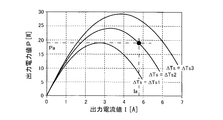
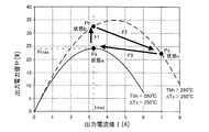
- thermoelectric power generation apparatus having the configuration as described above generates power corresponding to the magnitude of the temperature difference (heat source temperature difference) between the high temperature heat source and the low temperature heat source. For example, as long as the heat source temperature difference ⁇ Ts increases, the output power value P from the thermoelectric power generation module generally increases, for example, as illustrated in the graph of FIG. 1, unless problems such as breakage of the thermoelectric conversion element occur.
- the output power value P from the thermoelectric power generation module at a constant heat source temperature difference ⁇ Ts changes according to the output current value I from the thermoelectric power generation module.
- the output power value P from the thermoelectric power generation module is the maximum value (maximum output power value Pp) at a specific output current value Ip.
- the output power value P increases as the output current value I increases in the region below the specific output current value Ip, and the output current value I increases in the region above the specific output current value Ip
- the output power value P decreases.
- the relationship between the output current value I and the output power value P as described above changes depending on the magnitude of the heat source temperature difference ⁇ Ts, and a specific output current value Ip and the specific output current at which the maximum output power value Pp can be obtained.
- the maximum output power value Pp obtained at the value Ip also differs depending on the magnitude of the heat source temperature difference ⁇ Ts.
- the specific output current value Ip increases to Ip1, Ip2 and Ip3
- the maximum output power value Pp Becomes large as Pp1, Pp2 and Pp3. Therefore, in order to always obtain the maximum output power value Pp in the thermoelectric generator, it is necessary to adjust the output current value I in accordance with the magnitude of the heat source temperature difference ⁇ Ts from time to time (see, for example, Patent Document 1). ).
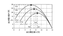
- the output power value P from the thermoelectric power generation module at a constant heat source temperature difference ⁇ Ts also changes depending on the output voltage value V from the thermoelectric power generation module. Specifically, for example, as shown in the graph of FIG. 4, the output power value P from the thermoelectric power generation module becomes the maximum value (maximum output power value Pp) at a specific output voltage value Vp. In other words, the output power value P increases as the output voltage value V increases in the region below the specific output voltage value Vp, and as the output voltage value V increases in the region above the specific output current value Vp. The output power value P decreases.
- the relationship between the output voltage value V and the output power value P as described above changes depending on the magnitude of the heat source temperature difference ⁇ Ts, and a specific output voltage value Vp and the specific output voltage at which the maximum output power value Pp can be obtained.
- the maximum output power value Pp obtained at the value Vp also differs depending on the magnitude of the heat source temperature difference ⁇ Ts.
- the specific output voltage value Vp decreases to Vp1, Vp2 and Vp3 and the maximum output power value Pp Becomes large as Pp1, Pp2 and Pp3. Therefore, in order to always obtain the maximum output power value Pp in the thermoelectric generation device, it is necessary to adjust the output voltage value V in accordance with the magnitude of the heat source temperature difference ⁇ Ts from time to time.
- a control method is known in the art, for example, to adjust the output current or output voltage from a power generation module such as a solar cell with a charge controller or a power conditioner (converter) or the like to extract the maximum power.
- a power generation module such as a solar cell with a charge controller or a power conditioner (converter) or the like to extract the maximum power.
- MPPT Maximum Power Point Tracking
- MPPT maximum power point tracking control
- the output current value I from the power generation module is gradually increased by current control of the controller, and the output current value I is further increased if the output power value P increases accordingly If the output power value P decreases, the output current value I is reduced to maximize the output power value P.
- MPPT is applied to a thermoelectric generator, as a result, as in the invention described in Patent Document 1, the output current value I is adjusted according to the magnitude of the heat source temperature difference ⁇ Ts, and the maximum output power value Pp can always be obtained from the thermoelectric generation module.
- the output power value P from the thermoelectric power generation module increases as the heat source temperature difference ⁇ Ts, which is the temperature difference between the high temperature heat source 10H and the low temperature heat source 10C, increases. . Therefore, in order to enhance the power generation efficiency, for example, the high temperature side interface temperature which is the temperature of the high temperature side interface Bh which is the interface on the high temperature heat source side of the thermoelectric conversion element It is preferable to operate the thermoelectric generator at a heat source temperature difference ⁇ Ts as large as possible within a range where Tbh does not exceed. Typically, it is preferable to operate the thermoelectric generator while maintaining the high temperature side interface temperature Tbh of the thermoelectric conversion element near the upper limit temperature Tmax.
- the high-temperature interface temperature Tbh may be higher than the upper limit temperature Tmax, which may lead to problems such as breakage of the thermoelectric conversion element.
- Measures 1 The high temperature side interface temperature Tbh is always maintained at a temperature lower than the upper limit temperature Tmax by a predetermined temperature range and operated.
- Measure 2 When the high temperature side interface temperature Tbh is likely to be higher than the upper limit temperature Tmax, the high temperature side interface Bh which is the interface on the high temperature heat source side of the thermoelectric conversion element is cooled by heat radiation.
- the measure 1 since the high temperature side interface temperature Tbh is always lower than the upper limit temperature Tmax by a predetermined temperature range, the maximum output power value Pp obtained when the high temperature side interface temperature Tbh is equal to the upper limit temperature Tmax. It is not possible to obtain the “critical output power value Pmax” which is On the other hand, according to the measure 2, it is essential to add a means (for example, a cooling device etc.) for heat radiation, which may lead to the complication of the thermoelectric power generation device, the enlargement, and the cost increase.
- a means for example, a cooling device etc.
- thermoelectric conversion element decreases due to heat radiation, so when the high temperature side interface temperature Tbh becomes sufficiently lower than the upper limit temperature Tmax, it is heated again to set the high temperature side interface temperature Tbh to the upper limit temperature Tmax. The time taken to approach and increase the output power value P becomes longer.
- thermoelectric-generation apparatus which can operate
- thermoelectric power generation device capable of operating with high power generation efficiency while preventing damage to the thermoelectric conversion element.
- thermoelectric conversion element if the current flowing through the thermoelectric conversion element is increased, the thermal conductivity of the thermoelectric conversion element increases and the interface on the low temperature heat source side from the interface on the high temperature heat source side It has been found that the high temperature side interface temperature of the thermoelectric conversion element can be rapidly and effectively lowered by utilizing the phenomenon in which the transfer of heat to the surface is promoted.
- thermoelectric power generation device includes a thermoelectric power generation module 10M, an output adjustment device 30, and a control unit Uc. It is.
- the thermoelectric generation module 10M includes a thermoelectric conversion element 10E that generates electric power by a heat source temperature difference ⁇ Ts that is a temperature difference between the high temperature heat source 10H and the low temperature heat source 10C.
- the output adjustment device 30 changes the output current value I which is the magnitude of the current output from the thermoelectric generation module 10M and / or the output voltage value V which is the magnitude of the voltage.
- the control unit Uc controls the output adjustment device 30 to control the output current value I and / or the output voltage value V.
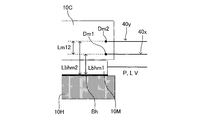
- the device according to the present invention detects the temperature measurement point temperature Tm which is the temperature of the temperature measurement point Dm which is at least one portion included in any of the high temperature heat source 10H, the low temperature heat source 10C, and the thermoelectric conversion module 10M.
- the apparatus 40 is further provided.
- the output adjustment device 30 when it is determined that the high temperature side interface temperature Tbh is higher than the predetermined upper limit temperature Tmax based on at least the temperature measurement point temperature Tm, the output adjustment device 30 is controlled to output the output current value I.
- the control unit Uc is configured to increase or decrease the output voltage value V.
- the high temperature side interface temperature Tbh is the temperature of the high temperature side interface Bh which is the interface on the high temperature heat source 10H side of the thermoelectric conversion element 10E.
- the high temperature side interface temperature Tbh based on at least the temperature measurement point temperature Tm is higher than the predetermined upper limit temperature Tmax can be determined by various methods. For example, the difference between the temperature of the temperature measuring point Dm (temperature measuring point temperature Tm) and the temperature of another place, the thermal conductivity ⁇ m of the region between these two places and the heat passing area Am, and these two places Through heat amount W specified based on the distance Lm, the thermal conductivity ⁇ bhm and the heat passing area Abhm of the region between the temperature measurement point Dm and the high temperature side interface Bh, the temperature measurement point temperature Tm, and the temperature measurement The high temperature interface temperature Tbh can be specified based on the distance Lbhm between the point Dm and the high temperature interface Bh. For example, the temperature of another temperature measurement point, the temperature of the low-temperature heat source 10C, or the like can be adopted as the “temperature of the other part”.
- the inventive device may further comprise an output detection device 20.
- the output detection device 20 has an output power value P, which is the magnitude of the power output from the thermoelectric generation module 10M, and an output current value I and / or the magnitude of the voltage, which is the magnitude of the current output from the thermoelectric generation module.
- An output related value Mout which is a set of a plurality of detected values consisting of an output voltage value V, is detected.
- the control unit Uc can store in advance the first characteristic data, which is data representing the relationship between the heat source temperature difference ⁇ Ts and the output related value Mout.
- the control unit is configured to determine whether the high temperature interface temperature Tbh is higher than the upper limit temperature Tmax based on the output related value Mout detected by the output detection device 20 and the first characteristic data. obtain. The determination can also be made by various methods, as described in detail below.
- the output adjusting device 30 when it is determined that the high temperature side interface temperature Tbh is equal to or lower than the predetermined upper limit temperature Tmax, the output adjusting device 30 is controlled to maximize the output power value P and the output current value
- the control unit Uc may be configured to execute output maximization control which is control to change I and / or the output voltage value V. In this case, as described later in detail, it is possible to reduce the operation processing load for determining whether the high temperature side interface temperature Tbh is higher than the upper limit temperature Tmax.
- the output adjusting device 30 is controlled to increase the output current value I or the output voltage
- the control unit Uc is configured to decrease the value V.
- thermoelectric-generation apparatus 1st apparatus
- DELTA heat-source temperature difference
- thermoelectric-generation apparatus (1st apparatus) which concerns on 1st Embodiment of this invention. It is a typical graph which shows that the relationship between the output current value I from the thermoelectric generation module and the output power value P changes with the magnitude
- DELTA heat-source temperature difference
- thermoelectric generation device (eighth device) according to the eighth embodiment of the present invention It is. It is a schematic diagram which shows the structure of the thermoelectric-generation apparatus (Example apparatus 101) as one specific example of this invention apparatus.
- FIG. 15 is a schematic enlarged view of a portion A surrounded by a broken line in FIG. 14, and shows the vicinity of a location where two thermocouples are provided in a low-temperature heat source.
- thermoelectric power generation apparatus Example apparatus 102
- Example apparatus 102 thermoelectric power generation apparatus
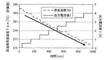
- It is a typical time chart explaining change of temperature of each part of example device 102 in control of high temperature side interface temperature Tbh performed in example device 102.
- thermoelectric generation device (hereinafter, may be referred to as a “first device”) according to the first embodiment of the present invention will be described.
- the first device is a thermoelectric power generation device including a thermoelectric power generation module, an output adjustment device, and a control unit.
- FIG. 6 is a schematic view showing an example of the configuration of the first device.
- the first device 100 includes a thermoelectric generation module 10M, an output adjustment device 30, and a control unit Uc.
- the thermoelectric generation module 10M includes a thermoelectric conversion element which is interposed between the high temperature heat source 10H and the low temperature heat source 10C and generates electric power by a heat source temperature difference ⁇ Ts which is a temperature difference between the high temperature heat source 10H and the low temperature heat source 10C.
- the heat source temperature difference ⁇ Ts is a temperature difference between the high temperature heat source 10H and the low temperature heat source 10C, and more specifically, the temperature at any position in the high temperature heat source 10H and the temperature at any position in the low temperature heat source 10C Difference.
- the heat source temperature difference ⁇ Ts is the difference between the temperature at the interface of the high temperature heat source 10H on the thermoelectric power generation module side and the temperature at the interface of the low temperature heat source 10C on the thermoelectric power generation module side.
- thermoelectric generation module 10M is not particularly limited as long as it is possible to generate power by the heat source temperature difference ⁇ Ts which is a temperature difference between the high temperature heat source 10H and the low temperature heat source 10C.
- the thermoelectric generation module 10M includes a pair of supporting substrates facing each other, electrodes formed respectively at predetermined positions on opposing surfaces of the pair of supporting substrates, and two different types of thermoelectric semiconductors. And an electrode member.
- the shape and size of the support substrate can be appropriately determined, for example, according to the application of the first device 100 and the like.
- the said electrode is comprised by a good conductor (for example, copper etc.), for example, is joined with a thermoelectric semiconductor by soldering.
- the pair of support substrates is a kind of so-called "wiring substrate”.
- thermoelectric semiconductors can also be appropriately selected according to, for example, the magnitude of the thermoelectric effect required for the application of the first device 100, and the like.
- a combination of a p-type thermoelectric semiconductor (for example, Bi 1.5 Sb 0.5 Te 3 or the like) and an n-type thermoelectric semiconductor (for example, Bi 2 Te 3 or the like) can be used.
- thermoelectric power generation module generally includes a plurality of different sets of two thermoelectric semiconductors for the purpose of achieving a larger thermoelectric effect.
- the plurality of two different types of thermoelectric semiconductors are alternately electrically connected in series by the electrodes to form a series electric circuit.
- thermoelectric conversion element 10E is configured. That is, the thermoelectric conversion element 10E has a so-called " ⁇ -type" structure. Then, the plurality of thermoelectric conversion elements 10E configured in this manner are conducted (electrically connected) in the same direction through the electrodes 12C formed on the other substrate 11C of the pair of substrates. That is, the plurality of two different types of thermoelectric semiconductors 10P and 10N are alternately and serially connected by the electrodes 12H and 12C to form a series electric circuit.
- thermoelectric generation module 10M it is general that a plurality of two different types of thermoelectric semiconductors 10P and 10N are sandwiched between the pair of support substrates 11H and 11C and arranged in a lattice-like arrangement. .
- thermoelectric generation module 10M can also be configured as a thermoelectric generation unit including a plurality of thermoelectric generation modules 10M electrically connected in series for the purpose of achieving a further larger thermoelectric effect or the like.
- thermoelectric generation module 10M another device supplied with the electric power output by the thermoelectric generation module 10M, another thermoelectric generation module constituting a thermoelectric generation unit including the thermoelectric generation module 10M, and a thermoelectric generation module It refers to devices other than the thermoelectric power generation module 10M, such as other devices to which the power output by the thermoelectric power generation unit including 10M is supplied.
- the output adjustment device 30 changes the output current value I which is the magnitude of the current output from the thermoelectric generation module 10M and / or the output voltage value V which is the magnitude of the voltage.
- the configuration of the output adjustment device 30 is not particularly limited as long as the output current value I and / or the output voltage value V can be changed.
- a device such as a DC-DC converter capable of adjusting the output current value I and / or the output voltage value V from the thermoelectric power generation module 10M may be mentioned. it can.
- thermoelectric generation module 10M a charge controller or power conditioner having a function of adjusting the output current value I and / or the output voltage value V from the thermoelectric generation module 10M A device such as a power supply can be used as the output adjustment device 30.
- the control unit Uc controls the output adjustment device 30 to control the output current value I and / or the output voltage value V.
- the configuration of the control unit Uc is not particularly limited as long as the output adjustment device 30 can be controlled to control the output current value I and / or the output voltage value V.
- an electronic control circuit (ECU) etc. which have a microcomputer containing CPU, ROM, RAM, an interface, etc. as a main component can be mentioned, for example.
- the CPU controls the output adjusting device to control the output current value I and / or the output voltage value V by executing an instruction (routine) stored in the memory (ROM).
- the control unit Uc may be implemented as an independent component separate from the other components configuring the first device 100, or the ECU included in the other components configuring the first device 100. And so on, the function as the control unit Uc may be realized. Furthermore, the function as the control unit Uc does not have to be necessarily realized in one component, and the function as the control unit Uc may be realized as a whole by processing performed in a plurality of components. In the example shown in FIG. 6, the ECU of the output adjustment device 30 realizes the function as the control unit Uc.
- the first device 100 can stably supply the output power from the thermoelectric generation module 10M to loads such as secondary batteries and electronic devices.
- the power supply destination 200 as such a load is connected to the output side of the output adjustment device 30.
- the high temperature side interface temperature Tbh becomes higher than the predetermined upper limit temperature Tmax, for example, breakage of the thermoelectric conversion element 10E And the like may lead to problems such as
- thermoelectric conversion element 10E cooling the high temperature side interface Bh (the portion indicated by the thick solid line in FIG. 7) which is the interface on the high temperature heat source 10H side of the thermoelectric conversion element 10E by heat radiation.
- a means heat radiation means
- it is necessary to add a means (heat radiation means) for heat radiation which may lead to the complication of the first device 100, an increase in size, and an increase in cost.
- the amount of heat held by the thermoelectric conversion element 10E is reduced by heat radiation, when the high temperature side interface temperature Tbh becomes sufficiently lower than the upper limit temperature Tmax, it is heated again and the high temperature side interface temperature Tbh becomes the upper limit temperature Tmax. The time required to increase the output power value P by increasing
- thermoelectric conversion element 10E when the current flowing to the thermoelectric conversion element 10E is increased, the thermal conductivity of the thermoelectric conversion element 10E increases, and the transfer of heat from the high temperature heat source 10H to the low temperature heat source 10C is promoted.
- the high temperature heat source side interface temperature Tbh can be lowered quickly and effectively. Specifically, for example, as shown in FIG. 8, when the output current value I is gradually increased with the passage of time, the high temperature side interface temperature Tbh of the thermoelectric conversion element 10E is lowered accordingly (arrows in the graph reference.).
- the first device 100 is a temperature measurement at a temperature measurement point Dm which is at least one portion included in any of the high temperature heat source 10H, the low temperature heat source 10C, and the thermoelectric conversion module 10M. It further comprises a temperature detection device 40 for detecting the point temperature Tm.
- a temperature detection device 40 for example, a temperature sensor or the like that directly measures the temperature of the temperature measurement point Dm, such as a thermocouple disposed at the temperature measurement point Dm, can be adopted.
- the temperature detection device 40 when it is difficult to arrange the temperature detection device 40 at a position where the temperature measurement point temperature Tm can be directly detected, the temperature can be detected at a position where the temperature having a correlation with the temperature measurement point temperature Tm can be detected.
- the detection device 40 may be provided, and the temperature measurement point temperature Tm may be calculated or estimated from the detection result.
- a thermo viewer using infrared light, a sensor that indirectly measures the temperature measurement point temperature Tm, or the like may be employed.
- the position of the temperature measurement point Dm is not particularly limited as long as the function as the thermoelectric generation module 10M is not substantially impaired, and any position in the high temperature heat source 10H, any position in the low temperature heat source 10C, and It can be any place in the thermoelectric generation module 10M. However, since it is often difficult to provide the temperature measurement point Dm in the thermoelectric power generation module 10M in practice, it is necessary to provide the temperature measurement point Dm at any position in the high temperature heat source 10H or in the low temperature heat source 10C. preferable. Typically, as shown in FIG. 6, the temperature measurement point Dm is provided at an arbitrary position in the high temperature heat source 10H.
- the high temperature side interface temperature Tbh which is the temperature of the high temperature side interface Bh which is the interface on the high temperature heat source side of the thermoelectric conversion element 10E is at least the predetermined upper limit temperature Tmax based on the temperature measurement point Tm.
- the controller Uc is configured to control the output adjustment device 30 to increase the output current value I or to decrease the output voltage value V when it is determined that the output voltage value V is also determined to be high.
- the above “upper limit temperature Tmax” can be determined based on, for example, the highest high temperature interface temperature Tbh unless problems such as breakage of the thermoelectric conversion element 10E occur due to the excessively high high temperature interface temperature Tbh. .
- a sudden fluctuation or the like of the temperature (high temperature heat source temperature Th) of a high temperature heat source such as exhaust from an internal combustion engine is also assumed.
- the upper limit temperature Tmax determined in this manner can be stored as data in a storage device such as a memory (ROM) included in the control unit Uc and can be referred to by the CPU as needed.
- ROM memory
- the high temperature side interface temperature Tbh is higher than the predetermined upper limit temperature Tmax based on at least the temperature measurement point temperature Tm, for example, it is detected in the first device 100
- Various techniques based on “various detected values correlated with the high temperature side interface temperature Tbh” can be mentioned.
- some detection means for detecting the value of the state quantity having a correlation with the high temperature side interface temperature Tbh may be further provided, and the determination may be made based on the detection result by the detection means. A specific method for making the determination will be described in detail in the description of another embodiment of the present invention described later.
- control unit Uc controls the output adjustment device 30 to determine the output current value I when it is determined that the high temperature interface temperature Tbh is higher than the upper limit temperature Tmax based on at least the temperature measurement point temperature Tm. It is configured to increase or to decrease the output voltage value V. Specifically, control unit Uc inputs an instruction signal for increasing output current value I or decreasing output voltage value V to, for example, a DC-DC converter as output adjustment device 30. Thus, the output current value I from the thermoelectric generation module 10M can be increased or the output voltage value V can be decreased.
- the increase width ⁇ I of the output current value I from the thermoelectric generation module 10M and the decrease width ⁇ V of the output voltage value V when the high temperature side interface temperature Tbh is determined to be higher than the predetermined upper limit temperature Tmax are It may be a predetermined fixed value.
- the increase width ⁇ I and the decrease width ⁇ V may be changed according to the magnitude of the difference between the high temperature side interface temperature Tbh and the upper limit temperature Tmax. In this case, specifically, for example, as the difference between the high temperature side interface temperature Tbh and the upper limit temperature Tmax is larger, the increase width ⁇ I and the decrease width ⁇ V may be larger.
- FIG. 9 is a flowchart showing an example of a control routine executed by the control unit in the first device 100.
- the CPU configuring the control unit is configured to repeatedly execute an instruction corresponding to the control routine stored in the memory (ROM) at a sufficiently short predetermined time interval.
- the CPU is required to make a determination as to whether or not the high temperature interface temperature Tbh is higher than a predetermined upper limit temperature Tmax in step S10. Get the detected value.
- the temperature measurement point temperature Tm which is the temperature of the temperature measurement point Dm which is at least one place included in any of the high temperature heat source 10H, the low temperature heat source 10C, and the thermoelectric conversion module is acquired from the temperature detection device 40 .
- the temperature of another location (for example, another measurement)
- the temperature of the hot spot or the temperature of the low temperature heat source 10C may be acquired.
- an output power value P which is the magnitude of the power output from the thermoelectric generation module
- an output voltage value the magnitude of the output current I and / or the voltage, which is the magnitude of the current output from the thermoelectric generation module
- An output related value Mout which is a set of a plurality of detection values consisting of V and V may be acquired.
- the CPU proceeds to step S20 and determines whether the high temperature side interface temperature Tbh is higher than the upper limit temperature Tmax.
- the specific method for performing the determination is appropriately selected according to the detection value acquired in step S10. For example, as described above, the difference between the temperature of the temperature measurement point Dm (temperature measurement point temperature Tm) and the temperature of another place, the thermal conductivity ⁇ m and the heat passing area Am of the region between these two places, and The penetrating heat amount W specified based on the distance Lm between these two places, the thermal conductivity ⁇ bhm and the heat passing area Abhm of the region between the temperature measurement point Dm and the high temperature side interface Bh, and the temperature measurement point temperature
- the high temperature interface temperature Tbh can be specified based on Tm and the distance Lbhm between the temperature measurement point Dm and the high temperature interface Bh.
- an output power value P which is a magnitude of power output from the thermoelectric generation module and an output current value I which is a magnitude of current output from the thermoelectric generation module and / or an output voltage value V which is a magnitude of voltage
- detects the output related value Mout which is a set of a plurality of detected values, and whether the high temperature side interface temperature Tbh is higher than the upper limit temperature Tmax based on the heat source temperature difference .DELTA.Ts specified from the output related value Mout. You can also judge The details of the specific example of the method for making such determination will be described in detail in the description of the other embodiments of the present invention described later.
- the CPU determines "No" in the above step S20, proceeds to the next step S90, and executes the control routine normally executed (hereinafter, "normal control routine") Control the output adjustment device 30 according to the above-mentioned), and control the output current value I and / or the output voltage value V.
- normal control routine is, for example, a control routine for maximizing the output power value P in accordance with the heat source temperature difference ⁇ Ts such as maximum power point tracking control (MPPT) described above.
- MPPT maximum power point tracking control
- the CPU determines “Yes” in the step S20 and proceeds to the next step S30. Then, the control routine for lowering the high temperature side interface temperature Tbh of the thermoelectric conversion element 10E by increasing the output current value I or decreasing the output voltage value V (hereinafter referred to as “cooling control routine” There). Specifically, the CPU generates, for example, an instruction signal for increasing the output current value I or decreasing the output voltage value V, and sends the instruction signal to the output adjustment device 30.
- the output adjustment device 30 (for example, a DC-DC converter or the like) that has received the instruction signal increases the output current value I from the thermoelectric generation module 10M or decreases the output voltage value V.
- the high temperature side interface temperature Tbh of the thermoelectric conversion element 10E decreases.
- thermoelectric conversion element 10E when the first device 100 determines that the high temperature side interface temperature Tbh is higher than the predetermined upper limit temperature Tmax based on at least the temperature measurement point temperature Tm, the output current value I from the thermoelectric generation module 10M The current flowing to the thermoelectric conversion element 10E is increased by increasing or decreasing the output voltage value V. As a result, the thermal conductivity of the thermoelectric conversion element 10E is increased, the amount of heat transferred from the high temperature heat source 10H to the low temperature heat source 10C is increased, and the temperature of the high temperature side interface Bh at the high temperature heat source side interface of the thermoelectric conversion element 10E is descend.
- the output current value I from the thermoelectric generation module 10M is increased or the output voltage value V is By reducing the temperature, the high temperature side interface temperature Tbh of the thermoelectric conversion element 10E can be lowered quickly and effectively. Thereby, for example, problems such as breakage of the thermoelectric conversion element 10E due to an excessive increase in the high temperature side interface temperature Tbh can be avoided.
- thermoelectric power generation device is complicated, enlarged and cost increase as in the case of cooling the thermoelectric conversion element 10E by the heat dissipation means as described above.
- heat is continuously supplied from the high temperature heat source 10H to the thermoelectric power generation module even while the high temperature side interface temperature Tbh of the thermoelectric conversion element is lowered by the increase of the output current value I or the decrease of the output voltage value V as described above. Therefore, when the high temperature side interface temperature Tbh becomes sufficiently lower than the upper limit temperature Tmax, when switching to the normal control routine, the high temperature side interface temperature Tbh quickly approaches the upper limit temperature Tmax to rapidly increase the output power value P It can be done.
- the cooling control routine described above may be executed in the first device 100 including the heat dissipation means for cooling the thermoelectric conversion element 10E. Since cooling of the thermoelectric conversion element 10E by the heat dissipation means requires a certain period of time, the high temperature of the thermoelectric conversion element 10E can be achieved by executing the cooling control routine in a period until the cooling efficiency of the thermoelectric conversion elements by the heat dissipation means sufficiently increases.
- the interface on the heat source side (high temperature side interface Bh) can be rapidly cooled.
- thermoelectric power generation apparatus can be achieved with high power generation efficiency while preventing the damage of the thermoelectric conversion element 10E. Can be operated.
- thermoelectric-generation apparatus (Hereafter, a “2nd apparatus” may be called.) Which concerns on 2nd Embodiment of this invention is demonstrated.
- the second device has the same configuration as the first device 100 described above except for the points described in the following (a) to (d).
- the temperature detection device 40 is two temperature measurement points separated by a predetermined distance in the heat flow direction, which is the flow direction of heat transferred from the high temperature heat source 10H to the low temperature heat source 10C via the thermoelectric power generation module 10M.
- the first temperature measurement point temperature Tm1 and the second temperature measurement point temperature Tm2, which are the temperatures of the first temperature measurement point Dm1 and the second temperature measurement point Dm2, are respectively detected.
- the control unit Uc is the difference between the first temperature measurement point temperature Tm1 and the second temperature measurement point temperature Tm2, and the heat in the region between the first temperature measurement point Dm1 and the second temperature measurement point Dm2 in the heat flow direction. From the high temperature heat source 10H to the low temperature heat source 10C via the thermoelectric generation module 10M based on the conductivity ⁇ m12 and the heat passing area Am12, and the distance Lm12 between the first temperature measurement point Dm1 and the second temperature measurement point Dm2 in the heat flow direction The through heat amount W, which is the magnitude of the moving heat amount, is specified.
- the controller Uc controls the first temperature measurement point temperature Tm1 and / or the second temperature measurement point temperature Tm2, the first temperature measurement point Dm1 and / or the second temperature measurement point Dm2 in the heat flow direction, and the high temperature side interface Bh Thermal conductivity ( ⁇ bhm1 and / or ⁇ bhm2) and heat passing area (Abhm1 and / or Abhm2) in the region between, heat penetration amount W, and first temperature measurement point Dm1 and / or second temperature measurement point Dm2 in the heat flow direction
- the high temperature interface temperature Tbh is specified based on the distance between the high temperature interface Bh and the high temperature interface Bh (Lbhm1 and / or Lbhm2).
- the control unit Uc is configured to determine whether the high temperature side interface temperature Tbh is higher than the upper limit temperature Tmax.
- the temperature detection device 40 provided in the second device is configured to have the first temperature measurement point temperatures Tm1 and the second temperature measurement points that are temperatures of the first temperature measurement point Dm1 and the second temperature measurement point Dm2. It is comprised so that each temperature measurement point temperature Tm2 may be detected.
- the first temperature measurement point temperature Tm1 and the second temperature measurement point temperature Tm2 are heat flows that are the flow directions of heat transferred from the high temperature heat source 10H to the low temperature heat source 10C via the thermoelectric power generation module 10M, respectively. They are the temperatures of the first temperature measurement point Dm1 and the second temperature measurement point Dm2, which are two temperature measurement points located at predetermined intervals in the direction.
- the specific positions of the first temperature measurement point Dm1 and the second temperature measurement point Dm2 are not particularly limited as long as they do not substantially impair the function as the thermoelectric power generation module, and any position in the high temperature heat source 10H, for example , Any place in the low temperature heat source 10C, and any place in the thermoelectric power generation module 10M.
- the first temperature measurement point Dm1 and the first temperature measurement point Dm1 may be provided anywhere in the high temperature heat source 10H or the low temperature heat source 10C. It is preferable to provide two temperature measurement points Dm2.
- the first temperature measurement point Dm1 and the second temperature measurement point Dm2 are provided at any two places in the low temperature heat source 10C.
- the penetrating heat amount W can be calculated by the following equation (1).
- the first temperature measurement point temperature Tm1 and the second temperature measurement point temperature Tm2 can be obtained from the temperature detection device 40, and the thermal conductivity ⁇ m12, the heat passing area Am12 and the distance Lm12 are the values of the second device. It is a known value determined by the design specification.
- the control unit Uc controls the first temperature measurement point temperature Tm1 and / or the second temperature measurement point temperature Tm2, the first temperature measurement point Dm1 in the heat flow direction, and / or Thermal conductivity ( ⁇ bhm1 and / or ⁇ bhm2) and heat passing area (Abhm1 and / or Abhm2) of the region between the two temperature measurement points Dm2 and the high temperature side interface Bh, through heat amount W, and first temperature measurement in the heat flow direction
- the high temperature interface temperature Tbh is specified based on the distance (Lbhm1 and / or Lbhm2) between the point Dm1 and / or the second temperature measurement point Dm2 and the high temperature interface Bh.
- the high temperature side interface temperature Tbh can be calculated by the following equation (2) and / or equation (3).
- the first temperature measurement point temperature Tm1 and the second temperature measurement point temperature Tm2 can be obtained from the temperature detection device 40, and the thermal conductivity ⁇ bhm1 and ⁇ bhm2, the heat passing area Abhm1 and Abhm2 and the distances Lbhm1 and Lbhm2 are known values determined by the design specification of the second device.
- the high temperature interface temperature Tbh may be calculated using only one of the equations (2) and (3), or, for example, with the high temperature interface temperature Tbh calculated by the equation (2) An average value with the high temperature side interface temperature Tbh or the like calculated by the equation (3) may be adopted as the high temperature side interface temperature Tbh.
- the high temperature heat source 10H, the thermoelectric power generation module 10M and the low temperature heat source 10C are connected in series along one thermal circuit. Heat flows from the high temperature heat source 10H to the low temperature heat source 10C via the thermoelectric generation module 10M. Therefore, the penetration heat amount W is the same magnitude at any place of the thermal circuit in the device of the present invention. Further, the amount of heat moves from the interface between the high temperature heat source 10H and the thermoelectric power generation module 10M to the interface between the low temperature heat source 10C and the thermoelectric power generation module 10M.
- the device according to the present invention is generally constituted by a plate-like thermoelectric power generation module 10M interposed between the high temperature heat source 10H and the low temperature heat source 10C. Therefore, in this case, the heat passing area A can be regarded as having the same size at any position of the thermal circuit in the device of the present invention. That is, all the heat passing areas including the heat passing areas Am12, Abhm1 and Abhm2 can be regarded as having the same size at any position of the heat circuit in the device of the present invention.
- control unit Uc determines whether or not the high temperature side interface temperature Tbh specified as described in (c) above is higher than the upper limit temperature Tmax. It is configured to judge.
- thermoelectric power generation device with high power generation efficiency while preventing the damage of the thermoelectric conversion element 10E. Can be operated.
- thermoelectric generation device (hereinafter, may be referred to as a “third device”) according to a third embodiment of the present invention will be described.
- the high-temperature heat source temperature Th is likely to fluctuate depending on, for example, the operating state of the supply source (for example, an internal combustion engine or the like) of the high-temperature heat source 10C.
- the low-temperature heat source temperature Tc may be maintained at a constant temperature by, for example, the design specification of the thermoelectric power generation device. In this case, based on the difference between the temperature at the temperature measurement point Dm (temperature measurement point temperature Tm) and the temperature of an arbitrary point (the constant temperature corresponding to the low temperature heat source temperature Tc is maintained) in the low temperature heat source 10C.
- the high temperature side interface temperature Tbh can be specified.
- the third device has the same configuration as the above-described first device except for the points described in the following (e) to (g) and (d).
- the following (d) is the same as (d) in the second apparatus described above.
- the low temperature side temperature measurement point temperature Tmc which is the temperature of the low temperature side temperature measurement point Dmc which is at least one place contained in the low temperature heat source 10C is maintained at a constant temperature.
- the control unit Uc is the difference between the temperature measurement point temperature Tm and the low temperature side temperature measurement point temperature Tmc, and the flow direction of the heat moving from the high temperature heat source 10H to the low temperature heat source 10C via the thermoelectric generation module 10M.
- the thermal conductivity ⁇ mmc and heat passing area Ammc in the region between the temperature measurement point Dm and the low temperature side temperature measurement point Dmc in the heat flow direction, and the distance Lmmc between the temperature measurement point Dm and the low temperature side temperature measurement point Dmc in the heat flow direction Based on this, it is configured to identify the through heat amount W, which is the magnitude of the heat amount moving from the high temperature heat source 10H to the low temperature heat source 10C via the thermoelectric power generation module 10M.
- the control unit Uc measures the thermal conductivity of the region between the temperature measuring point Tm, the temperature measuring point Dm in the heat flow direction and / or the low temperature side temperature measuring point Dmc and the high temperature side interface Bh ( ⁇ bhm and / or ⁇ bhmc ) And heat passing area (Abhm and / or Abhmc), penetrating heat amount W, and distance between temperature measurement point Dm and / or low temperature side temperature measurement point Dmc in the heat flow direction and high temperature side interface Bh (Lbhm and / or Lbhmc) Based on this, it is configured to specify the high temperature side interface temperature Tbh.
- the control unit Uc is configured to determine whether the high temperature side interface temperature Tbh is higher than the upper limit temperature Tmax.
- the low temperature side temperature measurement point temperature Tmc which is the temperature of the low temperature side temperature measurement point Dmc which is at least one place included in the low temperature heat source 10C is a constant temperature
- the thermoelectric generator is maintained at The specific position of the low temperature side temperature measurement point Dmc is not particularly limited as long as the function as the thermoelectric power generation module is not substantially impaired, and for example, a constant temperature corresponding to the low temperature heat source temperature Tc in the low temperature heat source 10C Can be maintained anywhere).
- the low temperature heat source temperature Tc is maintained at a constant temperature in the third device
- the low temperature side temperature measurement point temperature Tmc is maintained at a constant temperature corresponding to the low temperature heat source temperature Tc. Therefore, in the third device, the penetrating heat amount W can be specified based on the temperature measurement point temperature Tm, the low temperature side measurement temperature Tmc, etc. without actually detecting the low temperature side temperature measurement temperature Tmc. It can be determined whether the side interface temperature Tbh is higher than the upper limit temperature Tmax. Therefore, since it is not necessary to add the structure for detecting low temperature side temperature measurement point temperature Tmc, problems, such as complication, the enlargement of a 3rd apparatus, and cost increase, for example can be avoided.
- the temperature detection device 40 provided in the third apparatus is configured to detect the low-temperature heat source temperature Tc, for example, for the purpose of maintaining the low-temperature heat source temperature Tc at a constant temperature, and detects the low-temperature heat source temperature Tc.
- the temperature measurement point Dc is included in the thermal circuit in which the heat quantity flows from the high temperature heat source 10H to the low temperature heat source 10C via the thermoelectric power generation module 10M
- the low temperature source temperature Tc is set as the low temperature side temperature measurement point temperature Tmc.
- Dc can be adopted as the low temperature side temperature measurement point Dmc. Also in this case, there is no need to add a configuration for detecting the low temperature side temperature measurement point temperature Tmc, so that, for example, problems such as the third device becoming complicated, large and cost increases can be avoided.
- the through heat amount W which is the amount of heat transferred from the high temperature heat source 10H to the low temperature heat source 10C via the thermoelectric power generation module 10M, is specified Is configured as.
- the penetrating heat amount W can be calculated by the following equation (4).
- the temperature measurement point temperature Tm can be obtained from the temperature detection device 40, and the low temperature side measurement temperature Tmc, the thermal conductivity ⁇ mmc, the heat passing area Ammc, and the distance Lmmc are the design of the third device It is a known value determined by the specification.
- the control unit Uc is between the temperature measurement point temperature Tm, the temperature measurement point Dm in the heat flow direction and / or the low temperature side temperature measurement point Dmc and the high temperature side interface Bh.
- the high temperature side interface temperature Tbh is specified based on the distance (Lbhm and / or Lbhmc) to the Specifically, the high temperature side interface temperature Tbh can be calculated by the following equation (5) and / or equation (6).
- the temperature measurement point temperature Tm can be obtained from the temperature detection device 40, and the low temperature side measurement temperature Tmc, the thermal conductivity ⁇ bhm and ⁇ bhmc, the heat passing area Abhm and Abhmc, And the distances Lbhm and Lbhmc are known values determined by the design specifications of the third device.
- the high temperature interface temperature Tbh may be calculated using only one of the equations (5) and (6), or, for example, with the high temperature interface temperature Tbh calculated by the equation (5) An average value with the high temperature side interface temperature Tbh or the like calculated by the equation (6) may be adopted as the high temperature side interface temperature Tbh.
- the penetrating heat amount W is the same in any part of the thermal circuit in the device of the present invention including the first device to the third device.
- the heat passing area A can be regarded as having the same size at any portion of the thermal circuit in the device of the present invention. That is, all heat passing areas including the passing areas Ammc, Abhm and Abhmc can be regarded as having the same size at any position of the thermal circuit in the device of the present invention.
- control unit Uc determines whether the high temperature side interface temperature Tbh specified as described in the above (g) is higher than the upper limit temperature Tmax. It is configured to judge.
- the third device By increasing the output current value I from the power generation module 10M or decreasing the output voltage value V, the current flowing through the thermoelectric conversion element 10E is increased. Therefore, the same effect as that of the first device described above can be achieved more reliably. That is, according to the third device, since the high temperature side interface temperature Tbh of the thermoelectric conversion element 10E can be lowered more quickly and effectively, the thermoelectric power generation device with high power generation efficiency while preventing the damage of the thermoelectric conversion element 10E. Can be operated.
- thermoelectric-generation apparatus (Hereafter, it may be called a "4th apparatus.") Which concerns on 4th Embodiment of this invention is demonstrated.
- the relationship between the heat source temperature difference ⁇ Ts and the output power value P and the output current value I and / or the output voltage value V in the thermoelectric generation module 10M is determined in advance by, for example, preliminary experiments using the thermoelectric generation module 10M.
- the heat source temperature difference ⁇ Ts can be specified from the output power value P and the output current value I and / or the output voltage value V during operation of the thermoelectric generation module 10M based on the relationship.
- the amount of through heat W can be specified based on the heat source temperature difference ⁇ Ts specified in this manner and the thermal conductivity ⁇ s of the corresponding region of the thermoelectric generation module 10M.
- the high temperature side interface temperature Tbh can be specified by, for example, the same method as the third device described above.
- the fourth device has the same configuration as the first device described above except for the points described in (h) to (l) and (d) below.
- the following (d) is the same as (d) in the second and third devices described above.
- the fourth device includes an output power value P which is a magnitude of power output from the thermoelectric generation module 10M, and an output current value I and / or a voltage which is a magnitude of current output from the thermoelectric generation module 10M. And an output detection device 20 for detecting an output related value Mout, which is a set of a plurality of detection values consisting of an output voltage value V which is a magnitude of.
- the control unit Uc stores in advance first characteristic data, which is data representing the relationship between the heat source temperature difference ⁇ Ts and the output related value Mout.
- the control unit Uc is configured to specify the heat source temperature difference ⁇ Ts based on the first characteristic data from the output related value Mout detected by the output detection device 20.
- the control unit Uc transfers the heat source temperature difference ⁇ Ts, the heat conductivity ⁇ s and the heat passing area As in the region where the heat source temperature difference ⁇ Ts is generated, and the high temperature heat source 10H to the low temperature heat source 10C via the thermoelectric power generation module 10M.
- the penetrating heat amount W is specified based on the length Ls of the region where the heat source temperature difference ⁇ Ts in the heat flow direction, which is the flow direction of the moving heat amount, is generated.
- the control unit Uc measures the temperature measuring point Tm, the thermal conductivity ⁇ bhm and the heat passing area Abhm of the region between the temperature measuring point Dm in the heat flow direction and the high temperature side interface Bh, the heat passing amount W, and the heat flow direction.
- the high temperature interface temperature Tbh is specified based on the distance Lbhm between the temperature measurement point Dm and the high temperature interface Bh.
- the control unit Uc is configured to determine whether the high temperature side interface temperature Tbh is higher than the upper limit temperature Tmax.
- the fourth device further includes the output detection device 20 for detecting the output related value Mout as described in (h) above.
- the output related value Mout is an output power value P which is a magnitude of power output from the thermoelectric generation module 10M, and an output current value I and / or a voltage which is a magnitude of current output from the thermoelectric generation module 10M. It is a set of a plurality of detected values consisting of an output voltage value V which is a magnitude.
- the output related value Mout may be a set of two detection values consisting of an output power value P and an output current value I, and is a set of two detection values consisting of an output power value P and an output voltage value V. Or a set of three detection values consisting of output power value P, output current value I and output voltage value V.
- the configuration of the output detection device 20 is not particularly limited as long as the output power value P and the output current value I and / or the output voltage value V can be detected.
- a current sensor, a voltage sensor, etc. can be mentioned, for example.
- a current sensor, a voltage sensor, or the like provided in another device to which the power output from the thermoelectric power generation module 10M is supplied, such as the output adjustment device 30 described above may be used as the output detection device 20.
- the control unit Uc stores in advance first characteristic data that is data representing the relationship between the heat source temperature difference ⁇ Ts and the output related value Mout.
- the first characteristic data is, for example, the heat source temperature difference ⁇ Ts, the output power value P, the output current value I, and / or the output voltage value V in the thermoelectric power generation module 10M by preliminary experiments using the fourth device. It can be obtained by previously determining the relationship of Further, the first characteristic data can be stored as electronic data representing the relationship in a storage device such as a memory (ROM) provided in the control unit.
- ROM memory
- the first characteristic data is not particularly limited as long as it is data representing the relationship between the heat source temperature difference ⁇ Ts and the output related value Mout.
- the first characteristic data may be a plurality of data tables or data maps representing the relationship between the output power value P and the output current value I or the output voltage value V collected at various heat source temperature differences ⁇ Ts.
- the first characteristic data may be one data table or data map representing the relationship among the heat source temperature difference ⁇ Ts, the output power value P, and the output current value I or the output voltage value V.
- the first characteristic data may be, for example, a function representing the relationship between the output power value P and the output current value I or the output voltage value V, which are collected at various heat source temperature differences ⁇ Ts.
- the first characteristic data may be one function representing the relationship between the heat source temperature difference ⁇ Ts, the output power, and the output current value I or the output voltage value V.
- the output related value Mout detected by the output detection device 20 it may be determined whether the high temperature side interface temperature Tbh is higher than the upper limit temperature Tmax as follows. it can.
- the control unit Uc specifies the heat source temperature difference ⁇ Ts at that time based on the first characteristic data from the output related value Mout detected by the output detection device 20 Is configured as.
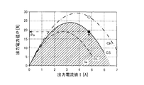
- the output detection device 20 detects the output power value Pa and the output current value Ia output from the thermoelectric generation module 10M at a certain point in time as the output related value Mout.
- the first characteristic data is assumed to be a plurality of data tables or data maps representing the relationship between the output power value P and the output current value I collected for each of the heat source temperature differences ⁇ Ts.
- the first characteristic data can be represented, for example, by the graph shown in FIG. Each curve in the graph of FIG.
- the control unit Uc includes the heat source temperature difference ⁇ Ts, the heat conductivity ⁇ s and the heat passing area As of the region where the heat source temperature difference ⁇ Ts is generated, and the thermoelectric power generation module 10M.
- the control unit Uc Based on the length Ls of the region where the heat source temperature difference ⁇ Ts occurs in the heat flow direction, which is the flow direction of heat transferred from the high temperature heat source 10H to the low temperature heat source 10C via, ing.
- the “region where the heat source temperature difference ⁇ Ts is generated” is, for example, detected at the high temperature heat source temperature Th which is a temperature detected at the temperature measurement point Dh in the high temperature heat source 10H and the temperature measurement point Dc in the low temperature heat source 10C.
- the heat source temperature difference ⁇ Ts is defined as the difference between the low temperature heat source temperature Tc which is a temperature, the fourth device (high temperature heat source 10H, thermoelectric generation module) located between the temperature measurement point Dh and the temperature measurement point Dc in the heat flow direction 10M, and a low temperature heat source 10C).
- the penetrating heat amount W can be calculated, for example, by the following equation (7).
- the heat source temperature difference ⁇ Ts can be specified as described in the above (j), and the thermal conductivity ⁇ s, the heat passing area As, and the distance (length) Ls are the fourth device It is a known value determined by the design specification of
- the control unit Uc measures the temperature measurement point temperature Tm, the heat conductivity ⁇ bhm of the region between the temperature measurement point Dm in the heat flow direction and the high temperature side interface Bh, and the heat passage.
- the high temperature interface temperature Tbh is specified based on the area Abhm, the penetrating heat amount W, and the distance Lbhm between the temperature measurement point Dm in the heat flow direction and the high temperature interface Bh.
- the high temperature side interface temperature Tbh can be calculated by the following equation (8).
- the temperature measurement point temperature Tm can be obtained from the temperature detection device 40, and the thermal conductivity ⁇ bhm, the heat passing area Abhm, and the distance Lbhm are known values determined by the design specification of the fourth device. .
- the penetrating heat amount W is the same in any part of the thermal circuit in the device of the present invention including the first device to the fourth device.
- the heat passing area A can be regarded as having the same size at any place in the device of the present invention. That is, all the heat passing areas including the heat passing areas As and Abhm can be regarded as having the same size at any position of the thermal circuit in the device of the present invention.
- control unit Uc determines whether or not the high temperature side interface temperature Tbh specified as described in (l) above is higher than the upper limit temperature Tmax. It is configured to judge.
- thermoelectric conversion element 10E it is determined that the high temperature side interface temperature Tbh specified based on the output related value Mout, the first characteristic data, and the temperature measurement point temperature Tm is higher than the predetermined upper limit temperature Tmax.
- the current flowing to the thermoelectric conversion element 10E is increased by increasing the output current value I from the thermoelectric generation module 10M or decreasing the output voltage value V. Therefore, the same effect as that of the first device described above can be achieved more reliably. That is, according to the fourth device, since the high temperature side interface temperature Tbh of the thermoelectric conversion element 10E can be lowered more quickly and effectively, the thermoelectric power generation device with high power generation efficiency while preventing the damage of the thermoelectric conversion element 10E. Can be operated.
- thermoelectric generation device (hereinafter, may be referred to as a “fifth device”) according to a fifth embodiment of the present invention will be described.
- the high temperature side interface temperature Tbh is higher than the predetermined upper limit temperature Tmax based on at least the temperature measurement point temperature Tm.
- the controller is configured to control the output adjusting device 30 to increase the output current value I or to decrease the output voltage value V when it is determined that Among the devices of the present invention, in the above-described second to fourth devices, the above determination is performed by specifying the high temperature side interface temperature Tbh based on at least the temperature measurement point temperature Tm. However, in order to carry out the above determination, it is not necessary to specify the high temperature side interface temperature Tbh itself.
- the fifth device calculates the upper limit penetrating heat amount Wmax which is the penetrating heat amount when the high temperature side interface temperature Tbh is equal to the upper limit temperature Tmax, and specifies the penetrating heat amount W at that point in the same manner as the fourth device described above. By comparing these, it is determined whether the high temperature side interface temperature Tbh is higher than the upper limit temperature Tmax.
- the fifth device has the same configuration as the first device described above except for the points described in (h) to (k) and (m) and (n) below.
- the following (h) to (k) are the same as (h) to (k) in the fourth device described above.
- the fifth device includes an output power value P, which is a magnitude of power output from the thermoelectric generation module 10M, and an output current value I and / or a voltage, which is a magnitude of current output from the thermoelectric generation module 10M. And an output detection device 20 for detecting an output related value Mout, which is a set of a plurality of detection values consisting of an output voltage value V which is a magnitude of.
- the control unit Uc stores in advance first characteristic data, which is data representing the relationship between the heat source temperature difference ⁇ Ts and the output related value Mout.
- the control unit Uc is configured to specify the heat source temperature difference ⁇ Ts based on the first characteristic data from the output related value Mout detected by the output detection device 20.
- the control unit Uc transfers the heat source temperature difference ⁇ Ts, the heat conductivity ⁇ s and the heat passing area As in the region where the heat source temperature difference ⁇ Ts is generated, and the high temperature heat source 10H to the low temperature heat source 10C via the thermoelectric power generation module 10M.
- the penetrating heat amount W is specified based on the length Ls of the region where the heat source temperature difference ⁇ Ts in the heat flow direction, which is the flow direction of the moving heat amount, is generated.
- the control unit Uc determines the difference between the temperature measurement point temperature Tm and the high temperature side interface temperature Tbh when the high temperature side interface temperature Tbh is equal to the upper limit temperature Tmax, and the temperature measurement point Dm in the heat flow direction and the high temperature side interface Bh. Temperature based on the thermal conductivity ⁇ bhm and heat passing area Abhm of the region between and the distance Lbhm between the temperature measurement point Dm and the high temperature side interface Bh in the heat flow direction, the temperature measurement when the high temperature side interface temperature Tbh is equal to the upper limit temperature Tmax It is comprised so that the upper limit penetration heat amount Wmax which is a magnitude
- the control unit Uc determines that the high temperature interface temperature Tbh is higher than the upper temperature Tmax when the through heat amount W is smaller than the upper limit heat amount Wmax. It is determined that the temperature is high and the high temperature interface temperature Tbh is higher than the upper limit temperature Tmax when the through heat quantity W is larger than the upper limit heat gain Wmax when the temperature measurement point Dm is closer to the low temperature heat source 10C than the high temperature side interface Bh. It is configured to
- control unit Uc is configured to specify the upper limit heat penetration amount Wmax.
- the upper limit penetration heat amount Wmax is the magnitude of the heat amount moving from the temperature measurement point Dm to the high temperature side interface Bh when the high temperature side interface temperature Tbh is equal to the upper limit temperature Tmax.
- the upper limit penetrating heat amount Wmax can be calculated, for example, by the following equation (9).
- the temperature measurement point temperature Tm can be obtained from the temperature detection device 40, and the upper limit temperature Tmax, the thermal conductivity ⁇ bhm, the heat passing area Abhm, and the distance (length) Lbhm is the design of the fifth device It is a known value determined by the specification. That is, the value of the upper limit penetrating heat amount Wmax is uniquely determined by the temperature measurement point temperature Tm.
- the position of the temperature measurement point Dm is not particularly limited as long as it does not substantially impair the function as the thermoelectric generation module 10M.
- any position in the high temperature heat source 10H, the low temperature heat source 10C It can be any location within and any location within the thermoelectric generation module 10M. Therefore, the temperature measurement point Dm may be located on the high temperature heat source side with respect to the high temperature side interface Bh, and conversely, may be located on the low temperature heat source side with respect to the high temperature side interface Bh.
- the upper limit penetration heat amount Wmax is the amount of heat transferred from the temperature measurement point Dm to the high temperature side interface Bh when the high temperature side interface temperature Tbh is equal to the upper limit temperature Tmax.
- the through heat amount W calculated (for example, by the above-mentioned equation (7)) is to be equal to the upper limit through heat amount Wmax.
- the control unit Uc determines that the penetrating heat amount W is smaller than the upper limit penetrating heat amount Wmax. It is judged that the high temperature side interface temperature Tbh is higher than the upper limit temperature Tmax, and the high temperature side interface when the penetrating heat amount W is larger than the upper limit penetrating heat amount Wmax when the temperature measurement point Dm is closer to the low temperature heat source 10C than the high temperature side interface Bh.
- the temperature Tbh is configured to be determined to be higher than the upper limit temperature Tmax.
- the fifth device calculates the upper limit penetrating heat amount Wmax which is the penetrating heat amount when the high temperature side interface temperature Tbh is equal to the upper limit temperature Tmax, and in the same manner as the fourth device described above W is specified and compared with each other to determine whether the high temperature interface temperature Tbh is higher than the upper limit temperature Tmax. Therefore, in the fifth device, the above determination is performed without specifying the high temperature side interface temperature Tbh itself. That is, according to the fifth device, it is possible to reduce the operation processing load required to determine whether the high temperature side interface temperature Tbh is higher than the upper limit temperature Tmax.
- thermoelectric generation device (hereinafter, may be referred to as a “sixth device”) according to a sixth embodiment of the present invention will be described.
- the fifth device specifies the through heat amount W based on the heat source temperature difference ⁇ Ts specified from the output related value Mout at a certain point, and the through heat amount when the high temperature side interface temperature Tbh is equal to the upper limit temperature Tmax. It is determined whether the high temperature interface temperature Tbh is higher than the upper limit temperature Tmax by comparing with the upper limit through heat amount Wmax, which is the upper limit temperature Tb. However, when the low temperature heat source temperature Tc is maintained at a constant temperature, it is possible to determine whether the high temperature interface temperature Tbh is higher than the upper limit temperature Tmax without specifying the penetrating heat quantity W.
- the sixth device specifies the heat source temperature difference ⁇ Ts from the output related value Mout at a certain point on the assumption that the low temperature heat source temperature Tc is maintained at a constant temperature, and the high temperature side interface temperature Tbh is the upper limit temperature Tmax. It is determined whether the high temperature side interface temperature Tbh is higher than the upper limit temperature Tmax by comparing it with the upper limit heat source temperature difference ⁇ Tmax which is the heat source temperature difference in the case of being equal to.
- the sixth device is the same as the first device described above except for the points described in the following (e), (h) to (j), (m), and (o) and (p): It has the same configuration.
- the following (e) is the same as (e) in the third device described above, and the following (h) to (j) are the same as (h) to (j) in the fourth and fifth devices described above
- the same (m) below is the same as (m) in the fifth apparatus described above.
- the low temperature side temperature measurement point temperature Tmc which is the temperature of the low temperature side temperature measurement point Dmc which is at least one place contained in the low temperature heat source 10C is maintained at a constant temperature.
- the sixth device includes an output power value P which is a magnitude of power output from the thermoelectric generation module 10M, and an output current value I and / or a voltage which is a magnitude of current output from the thermoelectric generation module 10M. And an output detection device 20 for detecting an output related value Mout, which is a set of a plurality of detection values consisting of an output voltage value V which is a magnitude of.
- the control unit Uc stores in advance first characteristic data, which is data representing the relationship between the heat source temperature difference ⁇ Ts and the output related value Mout.
- the control unit Uc is configured to specify the heat source temperature difference ⁇ Ts based on the first characteristic data from the output related value Mout detected by the output detection device 20.
- the control unit Uc determines the difference between the temperature measurement point temperature Tm and the high temperature side interface temperature Tbh when the high temperature side interface temperature Tbh is equal to the upper limit temperature Tmax, (from the high temperature heat source 10H to the low temperature via the thermoelectric generation module 10M Thermal conductivity ⁇ bhm and heat passing area Abhm of the region between the temperature measurement point Dm and the high temperature side interface Bh in the heat flow direction, which is the flow direction of heat transferred to the heat source 10C, and the temperature measurement point Dm and the heat flow direction Based on the distance Lbhm to the high temperature side interface Bh, when the high temperature side interface temperature Tbh is equal to the upper limit temperature Tmax, specify the upper limit penetrating heat amount Wmax which is the amount of heat transferred from the temperature measurement point Dm to the high temperature side interface Bh. It is configured to
- the control unit Uc determines the upper limit heat penetration amount Wmax, the thermal conductivity ⁇ s and the heat passing area As in the region where the heat source temperature difference ⁇ Ts is generated, and the length Ls in the heat flow direction of the region where the heat source temperature difference ⁇ Ts is generated
- the upper limit heat source temperature difference ⁇ Tmax which is a temperature difference between the high temperature heat source 10H and the low temperature heat source 10C when the high temperature side interface temperature Tbh is equal to the upper limit temperature Tmax, is specified based on
- the control unit Uc is configured to determine that the high temperature side interface temperature Tbh is higher than the upper limit temperature Tmax when the heat source temperature difference ⁇ Ts is larger than the upper limit heat source temperature difference ⁇ Tmax.
- control unit Uc is configured to specify the upper limit heat source temperature difference ⁇ Tmax.
- the upper limit heat source temperature difference ⁇ Tmax is a temperature difference between the high temperature heat source 10H and the low temperature heat source 10C when the high temperature side interface temperature Tbh is equal to the upper limit temperature Tmax.
- the upper limit heat source temperature difference ⁇ Tmax is the length of the upper limit heat gain Wmax, the thermal conductivity ⁇ s and heat passing area As of the region where the heat source temperature difference ⁇ Ts is occurring, and the heat flow direction of the region where the heat source temperature difference is occurring. It can identify based on.
- the upper limit heat source temperature difference ⁇ Tmax can be calculated, for example, by the following equation (10).
- the upper limit through heat quantity Wmax can be specified as described in the above (m)
- the thermal conductivity ⁇ s, the heat passing area As, and the distance (length) Ls are the sixth device It is a known value determined by the design specification of
- the upper limit heat source temperature difference ⁇ Tmax is a temperature difference between the high temperature heat source 10H and the low temperature heat source 10C when the high temperature side interface temperature Tbh is equal to the upper limit temperature Tmax.
- the low temperature measurement point temperature Tmc which is the temperature of the low temperature measurement point Dmc which is at least one portion included in the low temperature heat source 10C is It is maintained at a constant temperature. In other words, the temperature of the low temperature heat source 10C (low temperature heat source temperature Tc) is maintained at a constant temperature.
- the heat source temperature difference ⁇ Ts specified as such should be equal to the upper limit heat source temperature difference ⁇ Tmax.
- control unit Uc determines that the high temperature side interface temperature Tbh is higher than the upper limit temperature Tmax when the heat source temperature difference ⁇ Ts is larger than the upper limit heat source temperature difference ⁇ Tmax. Is configured.
- the sixth device calculates the upper limit heat source temperature difference ⁇ Tmax, which is a temperature difference between the high temperature heat source 10H and the low temperature heat source 10C when the high temperature side interface temperature Tbh is equal to the upper limit temperature Tmax, and In the same manner as the fifth device, the heat source temperature difference ⁇ Ts at that time is specified, and by comparing them, it is determined whether the high temperature side interface temperature Tbh is higher than the upper limit temperature Tmax. Therefore, in the sixth device, the above determination is performed without specifying the high temperature side interface temperature Tbh itself. That is, according to the sixth device, it is possible to reduce the operation processing load required to determine whether the high temperature side interface temperature Tbh is higher than the upper limit temperature Tmax.
- thermoelectric generation device (hereinafter, may be referred to as a “seventh device”) according to a seventh embodiment of the present invention will be described.
- the sixth device specifies the heat source temperature difference ⁇ Ts from the output related value Mout at a certain point on the premise that the low temperature heat source temperature Tc is maintained at a constant temperature, and the high temperature side interface temperature Tbh It is determined whether the high temperature interface temperature Tbh is higher than the upper limit temperature Tmax by comparing the upper heat source temperature difference ⁇ Tmax, which is the heat source temperature difference when the upper limit temperature Tmax is equal. That is, in the sixth device, the heat source temperature difference ⁇ Ts specified from the output related value Mout is employed as an index for determining whether the high temperature side interface temperature Tbh is higher than the upper limit temperature Tmax.
- the output related value Mout detected at a certain point ie, the output power value P and the output current value I and / or the output voltage value V
- the curve representing the relationship between the output power value P and the output current value I and the curve representing the relationship between the output power value P and the output voltage value V As the temperature difference ⁇ Ts increases, the output power value P shifts in the direction of increasing.
- the plot corresponding to the output related value Mout when the high temperature side interface temperature Tbh is higher than the upper limit temperature Tmax when the low temperature heat source temperature Tc is maintained at a constant temperature the heat source temperature difference ⁇ Ts is the upper limit heat source temperature difference It should be located on the side where the output power value P is larger (outside of the curve) with respect to the curve when it is equal to ⁇ Tmax.
- the plot corresponding to the output related value Mout when the high temperature side interface temperature Tbh is lower than the upper limit temperature Tmax shows that the output power value P is higher than the curve when the heat source temperature difference ⁇ Ts is equal to the upper heat source temperature difference ⁇ Tmax. It should be located on the smaller side (inside the curve).
- the curve drawn by the solid line in the graph of FIG. 11 is the output power value P when the heat source temperature difference ⁇ Ts is equal to the upper heat source temperature difference ⁇ Tmax (ie, when the high temperature interface temperature Tbh is equal to the upper temperature limit Tmax) And a curve (reference curve CS) representing the relationship between the current value and the output current value I.
- the heat source temperature difference ⁇ Ts is smaller than the upper heat source temperature difference ⁇ Tmax.
- the curve representing the relationship between the output power value P and the output current value I at this time point is the side where the output power value P is smaller than the reference curve CS, like the curve CL drawn by the broken line (reference Inside the curve CS). That is, a plot corresponding to the output related value Mout when the high temperature side interface temperature Tbh is lower than the upper limit temperature Tmax should exist inside (hatched portion) of the reference curve CS.
- the curve representing the relationship between the output power value P and the output current value I at this time point is the side where the output power value P is larger than the reference curve CS, like the curve CH drawn by the alternate long and short dash line (Outside of the reference curve CS). That is, the plot corresponding to the output related value Mout when the high temperature side interface temperature Tbh is higher than the upper limit temperature Tmax is on the outer side of the reference curve CS (the side where the output power value P is larger than the hatched portion). is there.
- the plot corresponding to the output related value Mout at that point shows that the heat source temperature difference ⁇ Ts is equal to the upper limit heat source temperature difference ⁇ Tmax
- the output related value Mout (that is, the output power value P and the output current value I and / or the output voltage value V) is used as an index for determining whether the high temperature side interface temperature Tbh is higher than the upper limit temperature Tmax. Any of the detection values to be configured may be adopted.
- the seventh device specifies an upper limit output power value Pmax which is an output power value when the high temperature side interface temperature Tbh is equal to the upper limit temperature Tmax on the premise that the low temperature heat source temperature Tc is maintained at a constant temperature. Then, by comparing with the output power value P at that time, it is determined whether the high temperature side interface temperature Tbh is higher than the upper limit temperature Tmax.
- the seventh device is as described above except for the points described in (e), (h) and (i), (m) and (o), and (q) and (r) below. It has the same configuration as the first device.
- the following (e) is the same as (e) in the third and sixth devices described above, and the following (h) and (i) are (h) in the fourth to sixth devices described above.
- the following (m) is the same as (m) in the fifth device and the sixth device described above
- the following (o) is the same as (o) in the sixth device described above is there.
- the low temperature side temperature measurement point temperature Tmc which is the temperature of the low temperature side temperature measurement point Dmc which is at least one place contained in the low temperature heat source 10C is maintained at a constant temperature.
- the seventh device includes an output power value P, which is the magnitude of power output from the thermoelectric generation module 10M, and an output current value I and / or a voltage, which is the magnitude of current output from the thermoelectric generation module 10M. And an output detection device 20 for detecting an output related value Mout, which is a set of a plurality of detection values consisting of an output voltage value V which is a magnitude of.
- the control unit Uc stores in advance first characteristic data, which is data representing the relationship between the heat source temperature difference ⁇ Ts and the output related value Mout.
- the control unit Uc determines the difference between the temperature measurement point temperature Tm and the high temperature side interface temperature Tbh when the high temperature side interface temperature Tbh is equal to the upper limit temperature Tmax, (from the high temperature heat source 10H to the low temperature via the thermoelectric generation module 10M Thermal conductivity ⁇ bhm and heat passing area Abhm of the region between the temperature measurement point Dm and the high temperature side interface Bh in the heat flow direction, which is the flow direction of heat transferred to the heat source 10C, and the temperature measurement point Dm and the heat flow direction Based on the distance Lbhm to the high temperature side interface Bh, when the high temperature side interface temperature Tbh is equal to the upper limit temperature Tmax, specify the upper limit penetrating heat amount Wmax which is the amount of heat transferred from the temperature measurement point Dm to the high temperature side interface Bh. It is configured to
- the control unit Uc determines the upper limit heat penetration amount Wmax, the thermal conductivity ⁇ s and the heat passing area As in the region where the heat source temperature difference ⁇ Ts is generated, and the length Ls in the heat flow direction of the region where the heat source temperature difference ⁇ Ts is generated
- the upper limit heat source temperature difference ⁇ Tmax which is a temperature difference between the high temperature heat source 10H and the low temperature heat source 10C when the high temperature side interface temperature Tbh is equal to the upper limit temperature Tmax, is specified based on
- the control unit Uc determines that the heat source temperature difference ⁇ Ts is equal to the upper limit heat source temperature difference ⁇ Tmax and the output current value I and / or the output voltage value V is detected by the output detection device 20.
- the upper limit output power value Pmax which is the magnitude of the power output from the thermoelectric generation module 10M, is specified based on the first characteristic data.
- the control unit Uc is configured to determine that the high temperature side interface temperature Tbh is higher than the upper limit temperature Tmax when the output power value P detected by the output detection device 20 is larger than the upper limit output power value Pmax. ing.
- (e) is the same as (e) in the third and sixth devices, and (h) and (i) are (h) and (h) in the fourth to sixth devices.
- the same as i) and the above (m) is the same as (m) in the fifth device and the sixth device, and the above (o) is the same as (o) in the sixth device.
- the upper limit heat source temperature difference ⁇ Tmax can be specified as described in the above (o).
- the control unit Uc is configured to specify the upper limit output power value Pmax.
- the heat source temperature difference ⁇ Ts is equal to the upper limit heat source temperature difference ⁇ Tmax, and the output current value I and / or the output voltage value V is detected by the output detection device 20 output current value I and / or output voltage
- the upper limit heat source temperature difference ⁇ Tmax is a temperature difference between the high temperature heat source 10H and the low temperature heat source 10C when the high temperature side interface temperature Tbh is equal to the upper limit temperature Tmax.
- the upper limit output power value Pmax is the output current value I and / or the output voltage value V detected by the output detection device 20 when the high temperature interface temperature Tbh is equal to the upper limit temperature Tmax.
- it is an output power value that will be output from the thermoelectric generation module 10M when it is equal to the output voltage value V.
- the high temperature side interface This is the output power value of the crucible output from the thermoelectric generation module 10M when the temperature Tbh is equal to the upper limit temperature Tmax.
- the upper limit output power value Pmax is specified as follows, for example.
- the control unit Uc CPU included therein
- the control unit Uc outputs the output current value I and / or the output when the heat source temperature difference ⁇ T is equal to the upper limit heat source temperature difference ⁇ Tmax specified as described in (o) described above
- the relationship between the voltage value V and the output power value P is extracted from the first characteristic data. Specifically, for example, the relationship between the output current value I and the output power value P represented by the reference curve CS shown in FIG. 12 corresponds to the relationship.
- the output current value I and / or output voltage detected by the output detection device 20 based on the relationship between the output current value I and / or the output voltage value V and the output power value P extracted as described above
- the output power value P corresponding to the value V can be specified as the upper limit output power value Pmax.
- the output power value Pa corresponding to the output current value Ia is specified as the upper limit output power value Pmax.
- the upper limit output power value Pmax is higher on the high temperature side when the output current value I and / or the output voltage value V is equal to the output current value I and / or the output voltage value V detected by the output detection device 20
- This is the output power value of the crucible output from the thermoelectric generation module 10M when the interface temperature Tbh is equal to the upper limit temperature Tmax.
- the low temperature measurement point temperature Tmc which is the temperature of the low temperature measurement point Dmc which is at least one portion included in the low temperature heat source 10C is It is maintained at a constant temperature. In other words, the temperature of the low temperature heat source 10C (low temperature heat source temperature Tc) is maintained at a constant temperature.
- the output power value P detected by the output detection device 20 should be equal to the upper limit output power value Pmax.
- the control unit Uc sets the high temperature side interface temperature Tbh to the upper limit temperature. It is configured to determine that it is higher than Tmax.
- the low temperature heat source temperature Tc is maintained at a constant temperature. Therefore, in the seventh device, the output current value I and / or the output voltage value V is detected by the output detection device 20 when the high temperature interface temperature Tbh is equal to the upper limit temperature Tmax. While specifying the upper limit output power value Pmax which is an output power value to be output from the thermoelectric generation module 10M when it is equal to V, the thermoelectric generation module at that time in the same manner as the fourth to sixth devices described above By detecting the output power value P actually output from 10 M by the output detection device 20 and comparing them, it is determined whether the high temperature side interface temperature Tbh is higher than the upper limit temperature Tmax.
- the above determination is performed without specifying the high temperature side interface temperature Tbh itself. That is, according to the seventh apparatus, it is possible to reduce the operation processing load required to determine whether the high temperature side interface temperature Tbh is higher than the upper limit temperature Tmax.
- thermoelectric generation device a thermoelectric generation device according to the eighth embodiment of the present invention (hereinafter, may be referred to as “eighth device”) will be described.
- the seventh device is an upper limit output power value which is an output power value when the high temperature interface temperature Tbh is equal to the upper limit temperature Tmax on the premise that the low temperature heat source temperature Tc is maintained at a constant temperature. While specifying Pmax, the output power value P at that time is detected, and by comparing them, it is determined whether the high temperature interface temperature Tbh is higher than the upper limit temperature Tmax. That is, in the seventh device, the output power value P, which is one detected value constituting the output related value Mout, is adopted as an index for determining whether the high temperature side interface temperature Tbh is higher than the upper limit temperature Tmax. It is done. However, other detected values (i.e., output current value I and / or output voltage value V) that constitute the output related value Mout may be adopted as the index.
- other detected values i.e., output current value I and / or output voltage value V
- the eighth device is an upper limit that is an output current value and / or an output voltage value when the high temperature side interface temperature Tbh is equal to the upper limit temperature Tmax. It is determined whether the high temperature interface temperature Tbh is higher than the upper limit temperature Tmax by specifying the output related value Mmax and comparing it with the corresponding output related value Mout at that time.
- the eighth device is the same as the first device described above except for the points described in the following (e), (h) and (i), (m) and (o), and (s). It has the same configuration.
- the following (e) is the same as (e) in the third apparatus, the sixth apparatus and the seventh apparatus described above, and the following (h) and (i) in the fourth apparatus to the seventh apparatus described above.
- the same as (h) and (i) and the following (m) is the same as (m) in the fifth to seventh devices described above, and the following (o) is the sixth and seventh devices described above Same as (o) in the device. That is, the eighth apparatus has the same configuration as the seventh apparatus described above except that the eighth apparatus has the technical features described in (s) below instead of (q) and (r) described above.
- the low temperature side temperature measurement point temperature Tmc which is the temperature of the low temperature side temperature measurement point Dmc which is at least one place contained in the low temperature heat source 10C is maintained at a constant temperature.
- the seventh device includes an output power value P, which is the magnitude of power output from the thermoelectric generation module 10M, and an output current value I and / or a voltage, which is the magnitude of current output from the thermoelectric generation module 10M. And an output detection device 20 for detecting an output related value Mout, which is a set of a plurality of detection values consisting of an output voltage value V which is a magnitude of.
- the control unit Uc stores in advance first characteristic data, which is data representing the relationship between the heat source temperature difference ⁇ Ts and the output related value Mout.
- the control unit Uc determines the difference between the temperature measurement point temperature Tm and the high temperature side interface temperature Tbh when the high temperature side interface temperature Tbh is equal to the upper limit temperature Tmax, (from the high temperature heat source 10H to the low temperature via the thermoelectric generation module 10M Thermal conductivity ⁇ bhm and heat passing area Abhm of the region between the temperature measurement point Dm and the high temperature side interface Bh in the heat flow direction, which is the flow direction of heat transferred to the heat source 10C, and the temperature measurement point Dm and the heat flow direction Based on the distance Lbhm to the high temperature side interface Bh, when the high temperature side interface temperature Tbh is equal to the upper limit temperature Tmax, specify the upper limit penetrating heat amount Wmax which is the amount of heat transferred from the temperature measurement point Dm to the high temperature side interface Bh. It is configured to
- the control unit Uc determines the upper limit heat penetration amount Wmax, the thermal conductivity ⁇ s and the heat passing area As in the region where the heat source temperature difference ⁇ Ts is generated, and the length Ls in the heat flow direction of the region where the heat source temperature difference ⁇ Ts is generated
- the upper limit heat source temperature difference ⁇ Tmax which is a temperature difference between the high temperature heat source 10H and the low temperature heat source 10C when the high temperature side interface temperature Tbh is equal to the upper limit temperature Tmax, is specified based on
- the control unit Uc outputs the output from the thermoelectric generation module 10M when the heat source temperature difference ⁇ Ts is equal to the upper limit heat source temperature difference ⁇ Tmax and the output power value P is equal to the output power value P detected by the output detection device If the upper limit output related value Mmax which is the current I and / or the output voltage V is not specified based on the first characteristic data, or the upper limit output related value Mmax is specified based on the first characteristic data and is detected by the output detection device 20 It is configured to determine that the high temperature side interface temperature Tbh is higher than the upper limit temperature Tmax when the detected output current value I and / or the output voltage value V is larger or smaller than any of the upper limit output related value Mmax. There is.
- the above (e) is the same as the (e) in the third device, the sixth device and the seventh device, and the above (h) and (i) h) and (i), and the above (m) is the same as (m) in the fifth to seventh devices, and the above (o) is (o) in the sixth and seventh devices Since the description is omitted here, the upper limit heat source temperature difference ⁇ Tmax can be specified as described in the above (o).
- the upper limit output related value Mmax when the upper limit output related value Mmax is not identified based on the first characteristic data, or the upper limit output related value Mmax is the first characteristic data, as described in (s) above.
- the output current value I and / or the output voltage value V specified based on and detected by the output detection device 20 is larger or smaller than any of the upper limit output related value Mmax, the high temperature side interface temperature Tbh is higher than the upper limit temperature Tmax Is also configured to determine high.
- the upper limit output related value Mmax is output from the thermoelectric generation module 10M when the heat source temperature difference ⁇ Ts is equal to the upper limit heat source temperature difference ⁇ Tmax and the output power value P is equal to the output power value P detected by the output detection device 20
- the output current value I and / or the output voltage value V which will be.
- the maximum output power value Pp when the output power value Pa detected by the output detection device 20 at a certain point is equal to the heat source temperature difference ⁇ Ts equal to the upper limit heat source temperature difference ⁇ Tmax (ie critical power If it is equal to the power value Pmax) (see open circles), there is only one output current value Ia and / or output voltage value Va (not shown) that will be output from the thermoelectric generation module 10M .
- the plot of the output related value Mout when the high temperature side interface temperature Tbh is higher than the upper limit temperature Tmax exists outside the reference curve CS as described with reference to FIG. 11 regarding the seventh device.
- an output detection device 20 detects an output-related value Mout which is greater or smaller than.
- the output detection device 20 detects an output related value Mout that is larger or smaller than one upper limit output related value Mmax specified as described above, the high temperature side interface temperature Tbh at this point is the upper limit. It can be determined that the temperature is higher than the temperature Tmax.
- the output power value Pb detected by the output detection device 20 at a certain point in time is smaller than the critical output power value Pmax (see the solid circles)
- the output current that would be output from the thermoelectric generation module 10M There are two values Ib and / or two output voltage values Vb (not shown).
- the plot of the output related value Mout when the high temperature side interface temperature Tbh is higher than the upper limit temperature Tmax exists outside the reference curve CS.
- the two upper limit output related values Mmax specified as described above ie, two output current values Ia and / or output voltage value Va
- the output detection device 20 detects an output related value Mout which is larger or smaller than any of.
- the high temperature side interface temperature Tbh at this time point Can be determined to be higher than the upper limit temperature Tmax.
- the output power value Pc detected by the output detection device 20 at a certain point in time is larger than the critical output power value Pmax, the output current value and / or the output voltage value that will be output from the thermoelectric generation module 10M (1) It can not be identified based on characteristic data (there is no corresponding point on the reference curve CS). Also in this case, it can be determined that the high temperature side interface temperature Tbh at this time is higher than the upper limit temperature Tmax.
- the control unit Uc included in the eighth apparatus is configured to determine that the high temperature side interface temperature Tbh is higher than the upper limit temperature Tmax in the following two cases.
- the upper limit output related value Mmax which is the output voltage V is not specified based on the first characteristic data
- the upper limit output related value Mmax is specified based on the first characteristic data and detected by the output detection device 20
- the output current value I and / or the output voltage value V is larger or smaller than any of the upper limit output related value Mmax.
- the eighth device is output from the thermoelectric generation module 10M when the output power value P is equal to the output power value P detected by the output detection device 20 when the high temperature interface temperature Tbh is equal to the upper limit temperature Tmax.
- Mmax which is the output current I and / or the output voltage V
- thermoelectric generation device according to the ninth embodiment of the present invention (hereinafter, may be referred to as a "ninth device”) will be described.
- thermoelectric power generation device when it is determined that the high temperature side interface temperature Tbh is equal to or lower than the predetermined upper limit temperature Tmax, the output power value P is maximized
- the control unit Uc may be configured to execute output maximization control, which is control for controlling the output adjustment device 30 to change the output current value I and / or the output voltage value V. In this case, as described later in detail, it is possible to further reduce the calculation processing load for determining whether the high temperature side interface temperature Tbh is higher than the upper limit temperature Tmax.
- the ninth device is any one of various thermoelectric devices according to the present invention including the first to eighth devices described above, and the following (t) to (w) It further comprises the described features.
- the control unit Uc controls the output adjustment device 30 to maximize the output power value P, and outputs the output current value I It is configured to execute output maximization control which is control for changing the output voltage value V.
- MPPT maximum power point tracking control
- the output current value I from the power generation module is gradually increased by current control of the controller, and the output current value I is further increased if the output power value P increases accordingly If the output power value P decreases, the output current value I is reduced to maximize the output power value P.
- the control unit Uc determines the heat source temperature difference ⁇ Ts at the time of execution of the output maximization control and the index detection value Mindex which is at least one detection value out of a plurality of sets of detection values included in the output related value Mout.
- the second characteristic data which is data representing the relationship of, is stored as first characteristic data.
- the second characteristic data can also be obtained in advance by a preliminary experiment or the like using the ninth apparatus. Further, the second characteristic data can also be stored in a storage device such as a memory (ROM) provided in the control unit, similarly to the first characteristic data.
- a storage device such as a memory (ROM) provided in the control unit, similarly to the first characteristic data.
- the second characteristic data is not particularly limited as long as it is data representing the relationship between the heat source temperature difference ⁇ Ts and the index detection value Mindex.
- the second characteristic data may be one data table or data map representing the relationship between the heat source temperature difference ⁇ Ts, the maximum output power value Pp, and the corresponding specific output current value Ip or output voltage value Vp.
- the second characteristic data may be one function representing the relationship between the heat source temperature difference ⁇ Ts, the maximum output power value Pp, and the corresponding specific output current value Ip or output voltage value Vp.
- the output power value P, the output current value I and the output voltage value V corresponding to the respective heat source temperature differences ⁇ Ts are uniquely determined. Therefore, the amount of information of the second characteristic data is smaller than that of the first characteristic data in which the output power value P, the output current value I and the output voltage value V change at each heat source temperature difference ⁇ Ts, and the second characteristic data is stored. The capacity of the storage medium to do this can be reduced. Further, the arithmetic processing required to specify the heat source temperature difference ⁇ Ts and / or the upper limit heat source temperature difference ⁇ Tmax can be simplified.
- the control unit Uc is configured to specify the heat source temperature difference ⁇ Ts based on the second characteristic data from the index detection value Mindex detected by the output detection device 20.
- the ninth apparatus when it is determined that the high temperature side interface temperature Tbh is equal to or lower than the upper limit temperature Tmax, output maximization control is executed, and the output power value P is determined according to the heat source temperature difference ⁇ Ts at that time.
- the output current value I and / or the output voltage value V are controlled such that V.sub.max is maximum.
- the output adjusting device 30 is controlled to obtain the specific output current value Ip (and the specific output voltage value Vp) shown in FIG. 2, and the corresponding maximum output The power value Pp is achieved. That is, the output power value P, the output current value I, and the output voltage value V corresponding to each heat source temperature difference ⁇ Ts are uniquely determined.
- the heat source temperature difference ⁇ Ts and / or the upper limit heat source temperature difference ⁇ Tmax can be specified by an index detection value Mindex which is a detection value of at least one of a plurality of sets of detection values included in the output related value Mout.
- the control unit Uc stops the execution of the output maximizing control and controls the output adjusting device 30 to output the output current value I. It is configured to increase or to decrease the output voltage value V. That is, when it is determined that the high temperature side interface temperature Tbh is higher than the upper limit temperature Tmax, the control unit Uc performs thermoelectric conversion by increasing the output current value I or decreasing the output voltage value V as described above.
- a control routine (cooling control routine) for lowering the high temperature side interface temperature Tbh of the element 10E is configured to be executed.
- the high-temperature heat source side interface temperature Tbh of the thermoelectric conversion element 10E can be lowered quickly and effectively, so that breakage of the thermoelectric conversion element 10E is prevented.
- the thermoelectric generator can be operated with high power generation efficiency.
- the cooling control routine can be executed using the second characteristic data having a smaller data capacity than the first characteristic data. Therefore, it is possible to further reduce the calculation processing load for determining whether the high temperature side interface temperature Tbh is higher than the upper limit temperature Tmax.
- thermoelectric power generation device 101 one specific example of the thermoelectric power generation device according to the first embodiment of the present invention (hereinafter sometimes referred to as “the example device 101”) will be described with reference to FIGS. 14 and 15, etc. Details will be described below.
- FIG. 14 is a schematic view showing a configuration of a thermoelectric generation device (embodiment device 101) as one specific example of the device of the present invention.
- the example device 101 includes a thermoelectric generation module 10M, an output detection device 20, an output adjustment device 30, a temperature detection device 40, and a control unit 50.
- the thermoelectric generation module 10M includes a thermoelectric conversion element (not shown) that generates electric power by a heat source temperature difference ⁇ Ts that is a temperature difference between the high temperature heat source 10H and the low temperature heat source 10C.
- the thermoelectric conversion element is constituted by a series electric circuit formed of a plurality of two different types of thermoelectric semiconductors alternately connected in series alternately (not shown), and the high temperature heat source 10H and It is held by the low temperature heat source 10C.
- the output detection device 20 has an output power value P, which is a magnitude of output power that is power output from the thermoelectric generation module 10M, and an output current value I, which is a magnitude of current output from the thermoelectric generation module 10M. Alternatively, an output voltage value V which is the magnitude of the voltage is detected.
- the output adjustment device 30 changes the output current value I and / or the output voltage value V.
- the temperature detection device 40 detects the value of the state quantity that has a correlation with the high temperature side interface temperature Tbh.
- the control unit 50 controls the output adjustment device 30 to control the output current value I and / or the output voltage value V.
- a DC-DC converter (hereinafter, referred to as "DC-DC converter 30") as the power adjustment device 30 is connected to the thermoelectric power generation module 10M.
- the DC-DC converter 30 also includes an output detection device 20 and a temperature detection device 40, and boosts and smoothes the output power from the thermoelectric generation module 10M to supply power to a power supply destination (load) 200 such as a battery. Supply. Furthermore, the DC-DC converter 30 also functions as the control unit 50.
- thermocouples 40x and 40y are disposed in the low temperature heat source 10C, and these two thermocouples 40x and 40y are connected to the temperature detection device 40 included in the DC-DC converter 30.
- FIG. 15 is an enlarged view of a portion A surrounded by a broken line in FIG. 14 and shows the vicinity of the arrangement location of two thermocouples 40x and 40y (ie, temperature measurement points Dm1 and Dm2) in the low temperature heat source 10C.
- the other thermocouple 40y is disposed at a predetermined distance apart in the direction in which the high temperature heat source 10H and the low temperature heat source 10C sandwich the thermoelectric power generation module 10M (ie, the stacking direction thereof) There is.
- the temperature detection device 40 including the thermocouples 40x and 40y as temperature sensors has a predetermined distance in the heat flow direction, which is the flow direction of heat transferred from the high temperature heat source 10H to the low temperature heat source 10C via the thermoelectric power generation module 10M.
- a first temperature measurement point temperature Tm1 and a second temperature measurement point temperature Tm2 which are temperatures of the first temperature measurement point Dm1 and the second temperature measurement point Dm2 which are two temperature measurement points located apart by Lm12 respectively Is configured.
- thermoelectric generation module 10M data indicating the relationship between the output power value VP and the output current value I for each of the heat source temperature differences ⁇ Ts of the thermoelectric generation module 10M is stored in a storage device (not shown) included in the DC-DC converter 30. ing.
- This data corresponds to the first characteristic data which is data representing the relationship between the heat source temperature difference ⁇ Ts, the output power value P, the output current value I and / or the output voltage value V in the thermoelectric power generation module 10M described above.
- the CPU constituting the electronic control circuit (ECU) included in the DC-DC converter 30 which also functions as the control unit 50 executes the instructions (routine) stored in the memory (ROM) to execute the processing described below. Run.
- the control unit 50 calculates the difference between the temperatures of the two temperature measurement points Dm1 and Dm2 (first temperature measurement point temperature Tm1 and second measurement temperature Tm2) detected by the thermocouples 40x and 40y as temperature sensors, and the heat flow direction Thermal conductivity ⁇ m12 and heat passing area Am12 in the region between the first temperature measurement point Dm1 and the second temperature measurement point Dm2 in the second embodiment, and the distance between the first temperature measurement point Dm1 and the second temperature measurement point Dm2 in the heat flow direction From Lm12, based on the above-mentioned equation (1), the through heat amount W, which is the amount of heat transferred from the high temperature heat source 10H to the low temperature heat source 10C via the thermoelectric power generation module 10M, is calculated.
- the control unit 50 sets the first temperature measurement point temperature Tm1 and / or the second temperature measurement point temperature Tm2, the first temperature measurement point Dm1 and / or the second temperature measurement point Dm2 in the heat flow direction, and the high temperature side interface Bh.
- Thermal conductivity ⁇ bhm1 and / or ⁇ bhm2
- heat passing area Abhm1 and / or Abhm2
- heat penetration amount W heat penetration amount W
- the high temperature interface temperature Tbh is specified based on the distance to the high temperature interface Bh (Lbhm1 and / or Lbhm2). The above process corresponds to step S10 in the flowchart of FIG. 9 described above.
- control unit 50 controls the output adjustment device 30 according to the control routine (normal control routine) which is normally executed as described above. Control. This process corresponds to step S90 in the flowchart of FIG. 9 described above.
- control unit 50 performs a control routine (cooling control routine) to lower the high temperature side interface temperature Tbh of the thermoelectric conversion element 10E by increasing the output current value I. Run. This process corresponds to step S30 in the flowchart of FIG. 9 described above.
- the CPU constituting the electronic control circuit (ECU) included in the DC-DC converter 30 repeatedly executes the above routine at predetermined time intervals, whereby the high temperature interface temperature Tbh is the upper limit temperature Tmax.
- the thermoelectric generation module 10M can be operated with high power generation efficiency while maintaining the following to prevent damage of the thermoelectric generation element 10E.
- thermoelectric power generation device 102 is basically a thermoelectric power generation device having the same configuration as the example device 101 described above.
- the example device 101 based on the temperatures of the temperature measurement points Dm1 and Dm2 in the low temperature heat source 10C detected by the thermocouples 40x and 40y as the temperature sensors that constitute the temperature detection device 40. Whether or not the high temperature interface temperature Tbh is higher than the upper temperature limit Tmax is determined by comparing the calculated high temperature interface temperature Tbh with the upper temperature limit Tmax. However, in the embodiment apparatus 102, based on the output power value P and the like detected by the output detection device 20, it is determined whether the high temperature interface temperature Tbh is higher than the upper limit temperature Tmax.
- the output power from the thermoelectric generation module 10M increases as the heat source temperature difference ⁇ Ts increases, for example, unless problems such as breakage of the thermoelectric conversion element 10E occur.
- the value P increases.
- the output power value P from the thermoelectric generation module 10M is the maximum value (maximum output power value Pp) at a specific current value Ip. Become. In other words, the output power value P increases as the output current value I increases in the region below the specific output current Ip, and the output power as the output current value I increases in the region above the specific output current Ip The value P decreases.
- thermoelectric conversion element 10E configuring the thermoelectric generation module 10M accordingly The temperature of the side interface (high temperature side interface temperature Tbh) decreases.
- thermoelectric generation module 10M as described above and the upper limit (upper limit temperature Tmax) of the high temperature side interface temperature Tbh are the materials of the thermoelectric semiconductors (10N and 10P) constituting the thermoelectric generation module 10M and the thermoelectric semiconductor formed by the thermoelectric semiconductors It changes with the composition of conversion element 10E, etc.
- the above-mentioned maximum power point tracking control (MPPT) is usually controlled routine It is assumed that the control unit 50 is configured to execute as.
- thermoelectric generation module 10M the temperature (low-temperature heat source temperature Tc) of the low-temperature heat source 10C of the thermoelectric conversion element 10E constituting the thermoelectric generation module 10M is constantly maintained at a constant temperature of 30 ° C.
- the curve of the solid line in FIG. 16 shows the relationship between the output current value I and the output power value P in the state (state a) where the high temperature side interface temperature Tbh is equal to the upper limit temperature Tmax (280 ° C.).
- the heat source temperature difference ⁇ Ts at this time is 250 ° C.
- MPPT is executed as a normal control routine.
- the output current value I is adjusted to be about 3.3 A (Imax), and an output power Pa of about 24 W (critical output power value Pmax) is output.
- This state a corresponds to point A in the graph (time chart) of FIG.
- the temperature of the exhaust from the internal combustion engine as high temperature heat source 10H rises due to high load operation etc.
- the relationship between the output current value I and the output power value P when the high temperature side interface temperature Tbh reaches a temperature higher than the upper limit temperature Tmax (280 ° C.) (state b) is shown.
- the interface temperature difference ⁇ Ts increases.
- the output power value P changes because the high-temperature side interface temperature Tbh changes.
- the output power Pb in the state b is larger than the critical output power value Pmax.
- the critical output power value Pmax is, as described above, the maximum power Pp obtained when the high temperature interface temperature Tbh is equal to the upper limit temperature Tmax. Therefore, that the output power value P at a certain point in time is larger than the critical output power value Pmax means that the high temperature side interface temperature Tbh is higher than the upper limit temperature Tmax.
- the DC-DC converter as the output adjustment device 30 and the control unit 50 increases the output current value I from the thermoelectric generation module 10M according to the above-described cooling control routine.
- the output current I is increased from about 3.3 A to about 7 A (state c), as indicated by the arrow F2 in the graph of FIG.
- thermoelectric conversion element 10E constituting the thermoelectric generation module 10M is increased, and heat transfer from the interface on the high temperature heat source side (high temperature side interface Bh) to the interface on the low temperature heat source side (low temperature side interface Bc) Is promoted.
- the high temperature side interface temperature Tbh decreases, and the low temperature side interface temperature Tbc rises. That is, since the interface temperature difference ⁇ Tb decreases, the output power value P from the thermoelectric generation module 10M decreases to Pc (about 22.5 W).
- Pc about 22.5 W
- the above changes in the high temperature side interface temperature Tbh and the low temperature side interface temperature Tbc are due to the heat transfer between the high temperature side interface Bh and the low temperature side interface Bc of the thermoelectric conversion element 10E. It does not substantially affect the high temperature heat source temperature Th and the low temperature heat source temperature Tc. That is, the heat source temperature difference ⁇ Ts does not substantially change.
- the output current value I changes with the large value in the state c.
- the thermal conductivity of the thermoelectric conversion element 10E also remains high. Therefore, since the amount of heat transferred from the interface Bh on the high temperature heat source side to the interface Bc on the low temperature heat source also remains large, the high temperature side interface temperature Tbh decreases as shown by point D in the time chart of FIG. A temperature lower than the upper limit temperature Tmax (280 ° C.) is reached. As a result, the interface temperature difference ⁇ Tb further decreases, and the output power value P also decreases.
- the DC-DC converter 30 as the control unit 50 controls the output adjustment device 30 according to the normal control routine to control the output current value I.
- the output maximization control which is control for changing the output current value I by controlling the DC-DC converter 30 as the output adjusting device so that the output power value P becomes maximum.
- MPPT maximum power point tracking control
- the high temperature side interface temperature Tbh eventually returns to the vicinity of the upper limit temperature Tmax, and accordingly, as shown by the arrow F3 in the graph of FIG.
- the first output current value I and the output power value P from the thermoelectric generation module 10M detected by the output detection device 20 and the first stored in the storage device provided in the control unit 50 Based on the characteristic data, when it is determined that the high temperature side interface temperature Tbh is higher than the upper limit temperature Tmax, the output current value I is increased by the output adjusting device 30 and the temperature of the interface on the high temperature heat source 10H side of the thermoelectric generation module 10M The cooling control to lower (the high temperature side interface temperature Tbh) is executed.
- thermoelectric generation module 10M can be operated with high power generation efficiency while maintaining the high temperature side interface temperature Tbh at the upper limit temperature Tmax or less to prevent the breakage of the thermoelectric generation element 10E.
- thermoelectric generation module 10E: thermoelectric conversion element, 10N and 10P: thermoelectric semiconductor
- 10H high temperature heat source
- 10C low temperature heat source
- 11H support substrate (high temperature heat source side)
- 11C support substrate (low temperature heat source side)
- 12C ... electrode (low temperature heat source side) 20 ... output detection device, 30 ... output adjustment device (DC-DC converter), 40 ... temperature detection device, 40x and 40y ... thermocouple, 50 ... Control part, 100 ... thermoelectric generation device (first device), 101 and 102 ... thermoelectric generation device (embodiment device), and 200 ... power supply destination (load).
Landscapes
- Engineering & Computer Science (AREA)
- Power Engineering (AREA)
- Electromechanical Clocks (AREA)
Priority Applications (1)
| Application Number | Priority Date | Filing Date | Title |
|---|---|---|---|
| US16/964,078 US20210036205A1 (en) | 2018-01-24 | 2018-11-06 | Thermoelectric generation apparatus |
Applications Claiming Priority (2)
| Application Number | Priority Date | Filing Date | Title |
|---|---|---|---|
| JP2018-009765 | 2018-01-24 | ||
| JP2018009765A JP6754382B2 (ja) | 2018-01-24 | 2018-01-24 | 熱電発電装置 |
Publications (1)
| Publication Number | Publication Date |
|---|---|
| WO2019146210A1 true WO2019146210A1 (ja) | 2019-08-01 |
Family
ID=67396032
Family Applications (1)
| Application Number | Title | Priority Date | Filing Date |
|---|---|---|---|
| PCT/JP2018/041121 Ceased WO2019146210A1 (ja) | 2018-01-24 | 2018-11-06 | 熱電発電装置 |
Country Status (3)
| Country | Link |
|---|---|
| US (1) | US20210036205A1 (https=) |
| JP (1) | JP6754382B2 (https=) |
| WO (1) | WO2019146210A1 (https=) |
Cited By (1)
| Publication number | Priority date | Publication date | Assignee | Title |
|---|---|---|---|---|
| CN114930710A (zh) * | 2020-01-15 | 2022-08-19 | 株式会社Kelk | 热电发电装置 |
Families Citing this family (4)
| Publication number | Priority date | Publication date | Assignee | Title |
|---|---|---|---|---|
| KR20210136739A (ko) * | 2020-05-08 | 2021-11-17 | 주식회사 아이에스케이 | 열전 발전 모듈에 의한 전력 공급 장치 |
| JP7673438B2 (ja) * | 2021-03-13 | 2025-05-09 | 三菱マテリアル株式会社 | 熱流スイッチング装置 |
| CN115407853A (zh) * | 2022-08-29 | 2022-11-29 | 苏州浪潮智能科技有限公司 | 一种控制服务器温度的装置、方法及介质 |
| CN116336613B (zh) * | 2023-03-27 | 2025-10-17 | 珠海格力电器股份有限公司 | 多联机空调系统控制方法、装置、系统和存储介质 |
Citations (3)
| Publication number | Priority date | Publication date | Assignee | Title |
|---|---|---|---|---|
| JP2003332641A (ja) * | 2002-05-16 | 2003-11-21 | Seiko Instruments Inc | ペルチェ素子駆動回路 |
| JP2015188278A (ja) * | 2014-03-26 | 2015-10-29 | 株式会社Kelk | 熱電発電装置及び熱電発電方法 |
| JP2016098931A (ja) * | 2014-11-25 | 2016-05-30 | マツダ株式会社 | 自動車の高圧蓄圧器及び回生システム |
-
2018
- 2018-01-24 JP JP2018009765A patent/JP6754382B2/ja not_active Expired - Fee Related
- 2018-11-06 WO PCT/JP2018/041121 patent/WO2019146210A1/ja not_active Ceased
- 2018-11-06 US US16/964,078 patent/US20210036205A1/en not_active Abandoned
Patent Citations (3)
| Publication number | Priority date | Publication date | Assignee | Title |
|---|---|---|---|---|
| JP2003332641A (ja) * | 2002-05-16 | 2003-11-21 | Seiko Instruments Inc | ペルチェ素子駆動回路 |
| JP2015188278A (ja) * | 2014-03-26 | 2015-10-29 | 株式会社Kelk | 熱電発電装置及び熱電発電方法 |
| JP2016098931A (ja) * | 2014-11-25 | 2016-05-30 | マツダ株式会社 | 自動車の高圧蓄圧器及び回生システム |
Cited By (3)
| Publication number | Priority date | Publication date | Assignee | Title |
|---|---|---|---|---|
| CN114930710A (zh) * | 2020-01-15 | 2022-08-19 | 株式会社Kelk | 热电发电装置 |
| US20230052567A1 (en) * | 2020-01-15 | 2023-02-16 | Kelk Ltd. | Thermoelectric power generator |
| CN114930710B (zh) * | 2020-01-15 | 2025-11-18 | 株式会社Kelk | 热电发电装置 |
Also Published As
| Publication number | Publication date |
|---|---|
| JP6754382B2 (ja) | 2020-09-09 |
| JP2019129598A (ja) | 2019-08-01 |
| US20210036205A1 (en) | 2021-02-04 |
Similar Documents
| Publication | Publication Date | Title |
|---|---|---|
| WO2019146210A1 (ja) | 熱電発電装置 | |
| Mamur et al. | Application of a DC–DC boost converter with maximum power point tracking for low power thermoelectric generators | |
| Montecucco et al. | Maximum power point tracking converter based on the open-circuit voltage method for thermoelectric generators | |
| Kinsella et al. | Battery charging considerations in small scale electricity generation from a thermoelectric module | |
| Zhou et al. | A novel thermal management system for a cylindrical battery based on tubular thermoelectric generator | |
| Champier et al. | Thermoelectric power generation from biomass cook stoves | |
| Yu et al. | Thermoelectric automotive waste heat energy recovery using maximum power point tracking | |
| Huang et al. | A thermoelectric generator using loop heat pipe and design match for maximum-power generation | |
| US12341172B2 (en) | Heating control method for energy storage, energy storage system, and photovoltaic energy storage system | |
| CN111355005B (zh) | 用于电连接的组件及电池组或车辆 | |
| JP2012216423A (ja) | 温度ムラを考慮した熱入出量制御システム | |
| Alaoui | Thermal management for energy storage system for smart grid | |
| US11616181B2 (en) | Thermoelectric generator | |
| JP2012252887A (ja) | 外部環境からの熱量を考慮した温調制御システム | |
| JP2012216422A (ja) | 各電池の温度ばらつきの低減 | |
| Yuldoshev et al. | A Study of the Parameters of a Combined Photo-Thermoelectric Installation under Field Conditions | |
| US10516088B2 (en) | Pin coupling based thermoelectric device | |
| GB2450784A (en) | Thermoelectric power generator | |
| KR102142384B1 (ko) | 열전 발전 장치 및 그 제어방법 | |
| Yousefi et al. | Experimental investigation of the external load effect on thermoelectric generator discharge time in a low power energy harvesting system | |
| Doubabi et al. | Modeling and design of a solar-powered refrigerator for vaccines transportation in remote regions | |
| CN107017330A (zh) | 车辆的发电装置 | |
| Praveena et al. | Thermo electric generator module in driving the vehicle and monitoring using IoT | |
| Gurara et al. | A multi-mode four-switch buck-boost derived DC-DC converter with an intermediate battery interface for solar thermoelectric generation | |
| AGACAYAK et al. | The Effects of Speed and Flow Rate on Power in Thermoelectric Generators |
Legal Events
| Date | Code | Title | Description |
|---|---|---|---|
| 121 | Ep: the epo has been informed by wipo that ep was designated in this application |
Ref document number: 18902645 Country of ref document: EP Kind code of ref document: A1 |
|
| NENP | Non-entry into the national phase |
Ref country code: DE |
|
| 122 | Ep: pct application non-entry in european phase |
Ref document number: 18902645 Country of ref document: EP Kind code of ref document: A1 |