WO2019146071A1 - Refrigeration cycle device - Google Patents
Refrigeration cycle device Download PDFInfo
- Publication number
- WO2019146071A1 WO2019146071A1 PCT/JP2018/002475 JP2018002475W WO2019146071A1 WO 2019146071 A1 WO2019146071 A1 WO 2019146071A1 JP 2018002475 W JP2018002475 W JP 2018002475W WO 2019146071 A1 WO2019146071 A1 WO 2019146071A1
- Authority
- WO
- WIPO (PCT)
- Prior art keywords
- heat exchanger
- defrosting
- control
- refrigeration cycle
- state
- Prior art date
Links
- 238000005057 refrigeration Methods 0.000 title claims description 74
- 238000010257 thawing Methods 0.000 claims description 174
- 239000003507 refrigerant Substances 0.000 claims description 55
- 238000010438 heat treatment Methods 0.000 claims description 54
- 230000006870 function Effects 0.000 claims description 32
- 238000011144 upstream manufacturing Methods 0.000 claims description 3
- 230000004048 modification Effects 0.000 description 19
- 238000012986 modification Methods 0.000 description 19
- 238000010586 diagram Methods 0.000 description 14
- XLYOFNOQVPJJNP-UHFFFAOYSA-N water Substances O XLYOFNOQVPJJNP-UHFFFAOYSA-N 0.000 description 12
- 230000015572 biosynthetic process Effects 0.000 description 11
- 230000006837 decompression Effects 0.000 description 10
- 230000000694 effects Effects 0.000 description 8
- 238000001816 cooling Methods 0.000 description 7
- 239000000155 melt Substances 0.000 description 6
- 239000007788 liquid Substances 0.000 description 3
- 238000000034 method Methods 0.000 description 2
- 230000009467 reduction Effects 0.000 description 2
- 230000008719 thickening Effects 0.000 description 2
- 238000004378 air conditioning Methods 0.000 description 1
- 239000002131 composite material Substances 0.000 description 1
- 230000003247 decreasing effect Effects 0.000 description 1
- 230000006872 improvement Effects 0.000 description 1
- 230000005764 inhibitory process Effects 0.000 description 1
- 238000004519 manufacturing process Methods 0.000 description 1
- 238000002844 melting Methods 0.000 description 1
- 230000008018 melting Effects 0.000 description 1
- 239000004065 semiconductor Substances 0.000 description 1
- 239000013589 supplement Substances 0.000 description 1
Images


Classifications
-
- F—MECHANICAL ENGINEERING; LIGHTING; HEATING; WEAPONS; BLASTING
- F25—REFRIGERATION OR COOLING; COMBINED HEATING AND REFRIGERATION SYSTEMS; HEAT PUMP SYSTEMS; MANUFACTURE OR STORAGE OF ICE; LIQUEFACTION SOLIDIFICATION OF GASES
- F25B—REFRIGERATION MACHINES, PLANTS OR SYSTEMS; COMBINED HEATING AND REFRIGERATION SYSTEMS; HEAT PUMP SYSTEMS
- F25B5/00—Compression machines, plants or systems, with several evaporator circuits, e.g. for varying refrigerating capacity
- F25B5/02—Compression machines, plants or systems, with several evaporator circuits, e.g. for varying refrigerating capacity arranged in parallel
-
- F—MECHANICAL ENGINEERING; LIGHTING; HEATING; WEAPONS; BLASTING
- F25—REFRIGERATION OR COOLING; COMBINED HEATING AND REFRIGERATION SYSTEMS; HEAT PUMP SYSTEMS; MANUFACTURE OR STORAGE OF ICE; LIQUEFACTION SOLIDIFICATION OF GASES
- F25B—REFRIGERATION MACHINES, PLANTS OR SYSTEMS; COMBINED HEATING AND REFRIGERATION SYSTEMS; HEAT PUMP SYSTEMS
- F25B41/00—Fluid-circulation arrangements
- F25B41/20—Disposition of valves, e.g. of on-off valves or flow control valves
-
- F—MECHANICAL ENGINEERING; LIGHTING; HEATING; WEAPONS; BLASTING
- F25—REFRIGERATION OR COOLING; COMBINED HEATING AND REFRIGERATION SYSTEMS; HEAT PUMP SYSTEMS; MANUFACTURE OR STORAGE OF ICE; LIQUEFACTION SOLIDIFICATION OF GASES
- F25B—REFRIGERATION MACHINES, PLANTS OR SYSTEMS; COMBINED HEATING AND REFRIGERATION SYSTEMS; HEAT PUMP SYSTEMS
- F25B47/00—Arrangements for preventing or removing deposits or corrosion, not provided for in another subclass
- F25B47/02—Defrosting cycles
- F25B47/022—Defrosting cycles hot gas defrosting
-
- F—MECHANICAL ENGINEERING; LIGHTING; HEATING; WEAPONS; BLASTING
- F25—REFRIGERATION OR COOLING; COMBINED HEATING AND REFRIGERATION SYSTEMS; HEAT PUMP SYSTEMS; MANUFACTURE OR STORAGE OF ICE; LIQUEFACTION SOLIDIFICATION OF GASES
- F25B—REFRIGERATION MACHINES, PLANTS OR SYSTEMS; COMBINED HEATING AND REFRIGERATION SYSTEMS; HEAT PUMP SYSTEMS
- F25B49/00—Arrangement or mounting of control or safety devices
- F25B49/02—Arrangement or mounting of control or safety devices for compression type machines, plants or systems
-
- F—MECHANICAL ENGINEERING; LIGHTING; HEATING; WEAPONS; BLASTING
- F25—REFRIGERATION OR COOLING; COMBINED HEATING AND REFRIGERATION SYSTEMS; HEAT PUMP SYSTEMS; MANUFACTURE OR STORAGE OF ICE; LIQUEFACTION SOLIDIFICATION OF GASES
- F25B—REFRIGERATION MACHINES, PLANTS OR SYSTEMS; COMBINED HEATING AND REFRIGERATION SYSTEMS; HEAT PUMP SYSTEMS
- F25B6/00—Compression machines, plants or systems, with several condenser circuits
- F25B6/02—Compression machines, plants or systems, with several condenser circuits arranged in parallel
-
- F—MECHANICAL ENGINEERING; LIGHTING; HEATING; WEAPONS; BLASTING
- F25—REFRIGERATION OR COOLING; COMBINED HEATING AND REFRIGERATION SYSTEMS; HEAT PUMP SYSTEMS; MANUFACTURE OR STORAGE OF ICE; LIQUEFACTION SOLIDIFICATION OF GASES
- F25B—REFRIGERATION MACHINES, PLANTS OR SYSTEMS; COMBINED HEATING AND REFRIGERATION SYSTEMS; HEAT PUMP SYSTEMS
- F25B2300/00—Special arrangements or features for refrigeration machines, plants or systems, combined heating and refrigeration systems or heat-pump systems
-
- F—MECHANICAL ENGINEERING; LIGHTING; HEATING; WEAPONS; BLASTING
- F25—REFRIGERATION OR COOLING; COMBINED HEATING AND REFRIGERATION SYSTEMS; HEAT PUMP SYSTEMS; MANUFACTURE OR STORAGE OF ICE; LIQUEFACTION SOLIDIFICATION OF GASES
- F25B—REFRIGERATION MACHINES, PLANTS OR SYSTEMS; COMBINED HEATING AND REFRIGERATION SYSTEMS; HEAT PUMP SYSTEMS
- F25B2313/00—Compression machines, plants or systems with reversible cycle not otherwise provided for
- F25B2313/029—Control issues
- F25B2313/0294—Control issues related to the outdoor fan, e.g. controlling speed
-
- F—MECHANICAL ENGINEERING; LIGHTING; HEATING; WEAPONS; BLASTING
- F25—REFRIGERATION OR COOLING; COMBINED HEATING AND REFRIGERATION SYSTEMS; HEAT PUMP SYSTEMS; MANUFACTURE OR STORAGE OF ICE; LIQUEFACTION SOLIDIFICATION OF GASES
- F25B—REFRIGERATION MACHINES, PLANTS OR SYSTEMS; COMBINED HEATING AND REFRIGERATION SYSTEMS; HEAT PUMP SYSTEMS
- F25B2347/00—Details for preventing or removing deposits or corrosion
- F25B2347/02—Details of defrosting cycles
- F25B2347/021—Alternate defrosting
Definitions
- the present invention relates to a refrigeration cycle apparatus, and more particularly to a refrigeration cycle apparatus that executes a defrosting operation for melting frost formed in a heat exchanger.
- the conventional refrigeration cycle apparatus includes a refrigeration cycle including an indoor heat exchanger functioning as a condenser when performing a heating operation, and an outdoor heat exchanger having a lower heat exchanger and an upper heat exchanger.
- An apparatus has been proposed (see, for example, Patent Document 1).
- the upper heat exchanger is provided on the lower heat exchanger.
- the lower heat exchanger and the upper heat exchanger function as an evaporator, and as a result, the lower heat exchanger and the upper heat exchanger There is frost on the surface.
- the frost formed in the heat exchanger inhibits the heat exchange between the refrigerant flowing through the heat transfer tubes of the heat exchanger and the air passing through the heat exchanger. Therefore, when the frost is formed on the outdoor heat exchanger, the refrigeration cycle apparatus of Patent Document 1 performs the defrosting operation to melt the frost of the outdoor heat exchanger.
- the amount of frost remaining in the lower heat exchanger may increase at the end of the lower defrosting.
- the amount of frost remaining in the lower heat exchanger increases, heat exchange between the refrigerant in the heat transfer tubes of the lower heat exchanger and the air passing through the lower heat exchanger is impeded. As a result, the efficiency of the heating operation resumed after the defrosting operation is reduced.
- the present invention has been made to solve the problems as described above, and it is an object of the present invention to provide a refrigeration cycle apparatus capable of suppressing a decrease in the efficiency of heating operation.
- the refrigeration cycle apparatus includes a compressor, an indoor heat exchanger functioning as a condenser during heating operation, an upper heat exchanger provided above the lower heat exchanger and the lower heat exchanger. It has an outdoor heat exchanger that functions as an evaporator during heating operation, and is provided downstream of the indoor heat exchanger in the flow direction of the refrigerant during heating operation, and is more than the outdoor heat exchanger during heating operation.
- a pressure reducing device provided on the upstream side in the refrigerant flow direction, a first state connecting the discharge side of the compressor and the lower heat exchanger, and a second state connecting the discharge side of the compressor and the upper heat exchanger
- the control device includes a switching unit that switches between states and a control device that controls the switching state of the switching unit, and the control device performs switching of the switching unit when the control device performs a defrost operation that melts the frost of the outdoor heat exchanger.
- the first defrost control that sets the state to the first state is After the first defrosting control is performed, the second defrosting control is performed to set the switching state of the switching unit to the second state, and after the second defrosting control is performed, the switching of the switching unit is performed.
- a third defrost control is performed to set the state to the first state.
- the lower side heat exchanger at the start of the third defrosting control It is suppressed that a frost becomes thick, as a result, the fall of the efficiency of heating operation is suppressed.
- FIG. 1 It is a schematic block diagram of the refrigerating-cycle apparatus 100 which concerns on embodiment. It is a refrigerant circuit figure of refrigerating cycle device 100 concerning an embodiment. It is the figure which showed the outdoor heat exchanger 5 typically. It is a block diagram of a control function of refrigerating cycle device 100 concerning an embodiment. It is operation
- refrigerant circuit figure of modification 1 of refrigerating cycle device 100 concerning an embodiment. It is a refrigerant circuit figure of modification 2 of refrigerating cycle device 100 concerning an embodiment. It is a figure showing typically outdoor heat exchanger 5t of modification 3 of refrigerating cycle device 100 concerning an embodiment.
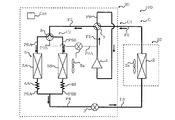
- FIG. 1 is a schematic configuration diagram of a refrigeration cycle apparatus 100 according to the embodiment.
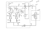
- FIG. 2 is a refrigerant circuit diagram of the refrigeration cycle apparatus 100 according to the embodiment.
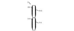
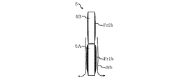
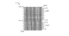
- FIG. 3 is a view schematically showing the outdoor heat exchanger 5.
- the refrigeration cycle apparatus 100 includes an outdoor unit 20 having an outdoor heat exchanger 5 and an indoor unit 30 connected to the outdoor unit 20 via a pipe P2 and a pipe P3.
- the refrigeration cycle apparatus 100 is an air conditioner.
- the refrigeration cycle apparatus 100 includes a heating operation in which the outdoor heat exchanger 5 functions as an evaporator, a cooling operation in which the outdoor heat exchanger 5 functions as a condenser, and a frost formed on the outdoor heat exchanger 5 during the heating operation. Defrosting operation, and can be performed.
- the outdoor unit 20 includes a compressor 1 for compressing a refrigerant, a decompression device 3 for decompressing a refrigerant, an outdoor heat exchanger 5 functioning as an evaporator during heating operation, and an outdoor unit for supplying air to the outdoor heat exchanger 5
- a fan 5 a and a flow path switching valve 9 provided on the discharge side of the compressor 1 are provided.
- the pressure reducing device 3 is provided downstream of the indoor heat exchanger 2 in the flow direction of the refrigerant during the heating operation, and is provided upstream of the outdoor heat exchanger 5 in the flow direction of the refrigerant during the heating operation. Moreover, as shown in FIG.
- the outdoor heat exchanger 5 has a lower heat exchanger 5A and an upper heat exchanger 5B provided on the lower heat exchanger 5A.
- the volume of the lower heat exchanger 5A and the volume of the upper heat exchanger 5B are the same.
- the lower heat exchanger 5A has a plate-like fin FnA and a heat transfer pipe hpA provided on the fin FnA and in which the refrigerant flows.
- the upper heat exchanger 5B has a plate-like fin FnB and a heat transfer pipe hpB provided on the fin FnB and in which the refrigerant flows.
- the outdoor unit 20 also includes a capillary tube 4A connected to the lower heat exchanger 5A and a capillary tube 4B connected to the upper heat exchanger 5B.
- the outdoor unit 20 also includes a switching unit 8 connected to the outdoor heat exchanger 5 and a valve 7 that opens and closes.
- the switching unit 8 has a first state connecting the discharge side of the compressor 1 and the lower heat exchanger 5A, a second state connecting the discharge side of the compressor 1 and the upper heat exchanger 5B, and outdoor heat. This is a valve that switches between the third state in which the exchanger 5 and the flow path switching valve 9 are connected.
- the outdoor unit 20 includes a control device Cnt that controls various actuators such as the compressor 1 and the like.
- the indoor unit 30 includes an indoor heat exchanger 2 that functions as a condenser during heating operation, and an indoor fan 2a that supplies air to the indoor heat exchanger 2.
- the refrigeration cycle apparatus 100 includes a refrigerant circuit C including a compressor 1, an indoor heat exchanger 2, a pressure reducing device 3, and an outdoor heat exchanger 5.
- the refrigerant circuit C includes a compressor 1, a flow path switching valve 9, an indoor heat exchanger 2, a pressure reducing device 3, a capillary tube 4A, a capillary tube 4B, an outdoor heat exchanger 5, a main circuit C1 having a switching unit 8, and a valve And a bypass circuit C2.
- the bypass circuit C2 bypasses the indoor heat exchanger 2 and the pressure reducing device 3 in the configuration of the main circuit C1.
- the main circuit C1 includes a pipe P1 connecting the discharge side of the compressor 1 and the flow path switching valve 9, a pipe P2 connecting the flow path switching valve 9 and the indoor heat exchanger 2, an indoor heat exchanger 2 and a pressure reducing device And a pipe P4 connected to the downstream side of the pressure reducing device 3 in the refrigerant flow direction during the heating operation.
- the main circuit C1 also includes a pipe P5A connecting the pipe P4 and the capillary tube 4A, a pipe P5B connecting the pipe P4 and the capillary tube 4B, and a pipe P6A connecting the lower heat exchanger 5A and the switching unit 8; It has piping P6B which connects the upper side heat exchanger 5B and the switching part 8. As shown in FIG.
- the main circuit C1 has a pipe P7 connecting the switching unit 8 and the flow path switching valve 9, and a pipe P8 connecting the flow path switching valve 9 and the suction side of the compressor 1.
- the bypass circuit C2 has a bypass pipe P9A connecting the pipe P1 and the valve 7 and a bypass pipe P9B connecting the valve 7 and the switching unit 8.
- the bypass pipe P9A and the bypass pipe P9B connect the discharge side of the compressor 1 and the switching unit 8.
- FIG. 4 is a block diagram of a control function of the refrigeration cycle apparatus 100 according to the embodiment.
- the control device Cnt includes an operation unit 50A that performs an operation, a control unit 50B that controls an actuator, and a storage unit 50C that stores data.
- the calculation unit 50A has a function of comparing the time elapsed since the start of various operations such as heating operation with a predetermined threshold.
- the control unit 50B controls the compressor 1, the pressure reducing device 3, the indoor blower 2a, the outdoor blower 5a, the valve 7, the switching unit 8, and the flow passage switching valve 9.
- the storage unit 50C stores data such as a threshold value used when shifting from the heating operation to the defrosting operation.
- Each functional unit included in the control device Cnt is configured by dedicated hardware or an MPU (Micro Processing Unit) that executes a program stored in a memory.
- the controller Cnt is a dedicated hardware
- the controller Cnt may be, for example, a single circuit, a composite circuit, an application specific integrated circuit (ASIC), a field-programmable gate array (FPGA), or a combination thereof.
- ASIC application specific integrated circuit
- FPGA field-programmable gate array
- Each of the functional units realized by the control device Cnt may be realized by individual hardware, or each functional unit may be realized by one hardware.
- each function executed by the control device is realized by software, firmware, or a combination of software and firmware. The software and firmware are described as a program and stored in the storage unit 50C.
- the MPU implements each function of the control device Cnt by reading and executing a program stored in the memory.
- the storage unit 50 is, for example, a non-volatile or volatile semiconductor memory such as a RAM, a ROM, a flash memory, an EPROM, and an EEPROM.
- FIG. 5 is an operation explanatory view of the heating operation of the refrigeration cycle apparatus 100 according to the embodiment.
- the switching state of the switching unit 8 is the third state. That is, the switching unit 8 connects the lower heat exchanger 5A and the flow path switching valve 9 and connects the upper heat exchanger 5B and the flow path switching valve 9. Further, in FIG. 5, the flow path switching valve 9 connects the discharge side of the compressor 1 to the indoor heat exchanger 2 and connects the switching portion 8 to the suction side of the compressor 1. Also, in FIG. 5, the valve 7 is closed. Furthermore, in FIG. 5, the indoor blower 2a and the outdoor blower 5a are in operation.
- the refrigerant discharged from the compressor 1 flows into the indoor heat exchanger 2 after passing through the flow path switching valve 9.
- the refrigerant flowing into the indoor heat exchanger 2 is liquefied.
- the refrigerant flowing out of the indoor heat exchanger 2 is decompressed by the decompression device 3.
- the refrigerant decompressed by the decompression device 3 is in a gas-liquid two-phase state.
- the refrigerant flowing out of the pressure reducing device 3 flows into the outdoor heat exchanger 5.
- the refrigerant flowing into the outdoor heat exchanger 5 is gasified.
- the refrigerant that has flowed out of the outdoor heat exchanger 5 returns to the compressor 1 after passing through the flow path switching valve 9.
- FIG. 6 is an operation explanatory view of the cooling operation of the refrigeration cycle apparatus 100 according to the embodiment.
- the switching state of the switching unit 8 is the third state.
- the flow path switching valve 9 connects the discharge side of the compressor 1 and the switching unit 8 and connects the indoor heat exchanger 2 and the suction side of the compressor 1.
- the valve 7 is closed.
- the indoor blower 2a and the outdoor blower 5a are in operation. The flow of the refrigerant during the cooling operation is opposite to the flow of the refrigerant during the heating operation described with reference to FIG.
- the defrosting method for the defrosting operation of the refrigeration cycle apparatus 100 is a hot gas defrosting method in which the hot gas discharged from the compressor 1 is supplied to the outdoor heat exchanger 5.
- the defrosting operation of the refrigeration cycle apparatus 100 is executed after the first defrosting control for defrosting the lower heat exchanger 5A and the first defrosting control to defrost the upper heat exchanger 5B.
- a second defrosting control and a third defrosting control that is executed after the second defrosting control to defrost the lower heat exchanger 5A are provided.
- FIG. 7 is an operation explanatory view of the first defrost control of the defrosting operation of the refrigeration cycle apparatus 100 according to the embodiment.
- the switching state of the switching unit 8 is in the first state. That is, the switching unit 8 connects the discharge side of the compressor 1 and the lower heat exchanger 5A, and connects the upper heat exchanger 5B and the flow path switching valve 9.
- the discharge side of the compressor 1 and the lower heat exchanger 5A are connected via the pipe P1, the bypass circuit C2, the switching unit 8, and the pipe P6A.
- the upper heat exchanger 5B and the flow path switching valve 9 are connected via the pipe P6B, the switching unit 8 and the pipe P7. Further, in FIG.
- the state of the flow path switching valve 9 is the same as the state of the flow path switching valve 9 in the heating operation described with reference to FIG. 5. Also, in FIG. 7, the valve 7 is open. Furthermore, in FIG. 7, the indoor blower 2a and the outdoor blower 5a are in operation.
- Part of the refrigerant discharged from the compressor 1 flows into the indoor heat exchanger 2 after passing through the flow path switching valve 9.
- the refrigerant flowing into the indoor heat exchanger 2 is liquefied. That is, even when the first defrosting control is performed, the indoor heat exchanger 2 functions as a condenser, so warm air is supplied to the room from the indoor unit 30.
- the refrigerant flowing out of the indoor heat exchanger 2 is decompressed by the decompression device 3.
- the refrigerant decompressed by the decompression device 3 is in a gas-liquid two-phase state.
- the other part of the refrigerant discharged from the compressor 1, that is, the hot gas flows into the lower heat exchanger 5A via the bypass circuit C2 and the switching unit 8.
- the heat of the hot gas flowing into the lower heat exchanger 5A is supplied to the frost of the lower heat exchanger 5A, and as a result, the frost of the lower heat exchanger 5A is melted.
- the refrigerant flowing out of the lower heat exchanger 5A merges with the refrigerant decompressed by the decompression device 3.
- the joined refrigerant flows into the upper heat exchanger 5B.
- the refrigerant flowing into the upper heat exchanger 5B is gasified. That is, in the first defrosting control, the upper heat exchanger 5B functions as an evaporator.
- the refrigerant flowing out of the upper heat exchanger 5B returns to the compressor 1 after passing through the flow path switching valve 9.
- FIG. 8 is an operation explanatory view of second defrosting control of the defrosting operation of the refrigeration cycle apparatus 100 according to the embodiment.
- the switching state of the switching unit 8 is in the second state. That is, the switching unit 8 connects the discharge side of the compressor 1 and the upper heat exchanger 5B, and connects the lower heat exchanger 5A and the flow path switching valve 9.
- the discharge side of the compressor 1 and the upper heat exchanger 5B are connected via the pipe P1, the bypass circuit C2, the switching unit 8, and the pipe P6B.
- the lower heat exchanger 5A and the flow path switching valve 9 are connected via the pipe P6A, the switching unit 8 and the pipe P7. Further, in FIG.
- the state of the flow path switching valve 9 is the same as the state of the flow path switching valve 9 in the heating operation described in FIG. 5. Also, in FIG. 8, the valve 7 is open. Furthermore, in FIG. 8, the indoor blower 2a and the outdoor blower 5a are in operation.
- the refrigerant flowing into the indoor heat exchanger 2 is liquefied. That is, even when the second defrosting control is performed as in the first defrosting control, the indoor heat exchanger 2 functions as a condenser, so warm air is supplied to the room from the indoor unit 30. .
- the refrigerant flowing out of the indoor heat exchanger 2 is decompressed by the decompression device 3.
- the refrigerant decompressed by the decompression device 3 is in a gas-liquid two-phase state.
- the other part of the refrigerant discharged from the compressor 1, that is, the hot gas flows into the upper heat exchanger 5B via the bypass circuit C2 and the switching unit 8.
- the heat of the hot gas flowing into the upper heat exchanger 5B is supplied to the frost of the upper heat exchanger 5B, and as a result, the frost of the upper heat exchanger 5B is melted.
- the refrigerant flowing out of the upper heat exchanger 5B merges with the refrigerant decompressed by the decompression device 3.
- the joined refrigerant flows into the lower heat exchanger 5A.
- the refrigerant flowing into the lower heat exchanger 5A is gasified. That is, in the second defrosting control, the lower heat exchanger 5A functions as an evaporator.
- the refrigerant flowing out of the lower heat exchanger 5A returns to the compressor 1 after passing through the flow path switching valve 9.
- FIG. 9 is an operation explanatory view of the third defrost control of the defrosting operation of the refrigeration cycle apparatus 100 according to the embodiment.
- the operation state of the third defrost control shown in FIG. 9 is the same as the operation state of the first defrost control shown in FIG. That is, in FIG. 9, the switching state of the switching unit 8 is in the first state. That is, the switching state of the switching unit 8 in the third defrosting control is the same as the switching state of the switching unit 8 in the first defrosting control.
- the state of the flow path switching valve 9 is the same as the state of the flow path switching valve 9 in the heating operation described with reference to FIG. 5. Also, in FIG. 9, the valve 7 is open. Furthermore, in FIG.
- the indoor blower 2a and the outdoor blower 5a are in operation.
- the flow of the refrigerant in the third defrosting control is the same as the flow of the refrigerant in the first defrosting control, and thus the description thereof will be omitted.
- FIG. 10 is a control flowchart of the refrigeration cycle apparatus 100 according to the embodiment.
- Control device Cnt starts the control flow concerning defrosting operation (Step S0).
- the control device Cnt acquires the time elapsed since the start of the heating operation, that is, the heating operation time ht (step S1).
- Arithmetic unit 50A of control device Cnt determines whether heating operation time ht is longer than predetermined time Th (step S2). If the heating operation time ht is longer than the predetermined time Th, the control device Cnt starts the defrosting operation (step S3).
- the control device Cnt executes the first defrosting control. That is, the control device Cnt switches the switching state of the switching unit 8 from the third state to the first state, and opens the valve 7. Further, the control device Cnt maintains the state of the flow path switching valve 9.
- the control device Cnt acquires the time elapsed since the start of the first defrosting control, that is, the execution time t1 of the first defrosting control (step S4).
- Arithmetic unit 50A of control device Cnt determines whether or not execution time t1 is longer than predetermined time T1 (step S5). If the execution time t1 is longer than the predetermined time T1, the control device Cnt ends the first defrost control and starts the second defrost control (step S6). That is, the control device Cnt switches the switching state of the switching unit 8 from the first state to the second state. Further, the control device Cnt keeps the valve 7 open and maintains the state of the flow path switching valve 9.
- the control device Cnt acquires the time elapsed since the start of the second defrosting control, that is, the execution time t2 of the second defrosting control (step S7).
- Arithmetic unit 50A of control device Cnt determines whether or not execution time t2 is longer than predetermined time T2 (step S8).
- time T1 is shorter than time T2. That is, the execution time of the first defrosting control is shorter than the execution time of the second defrosting control.
- the control device Cnt ends the second defrost control and starts the third defrost control (step S9). That is, the control device Cnt switches the switching state of the switching unit 8 from the second state to the first state. Further, the control device Cnt keeps the valve 7 open and maintains the state of the flow path switching valve 9.
- the control device Cnt acquires the time elapsed since the start of the third defrosting control, that is, the execution time t3 of the third defrosting control (step S10).
- Arithmetic unit 50A of control device Cnt determines whether or not execution time t3 is longer than predetermined time T3 (step S11).
- time T1 is shorter than time T3. That is, the execution time of the first defrosting control is shorter than the execution time of the third defrosting control. If the execution time t3 is longer than the predetermined time T3, the control device Cnt ends the third defrosting control (step S12). In step S12, the control device Cnt ends the defrosting operation and resumes the heating operation.
- control device Cnt switches the switching state of the switching unit 8 from the first state to the third state, and closes the valve 7. Further, the control device Cnt maintains the state of the flow path switching valve 9. The control device Cnt ends the control flow relating to the defrosting operation (step S13).
- FIG. 11 is a schematic view showing the state of the frost Fr1 formed in the lower heat exchanger 5A and the frost Fr2 formed in the upper heat exchanger 5B during the heating operation.
- the frost Fr1 is formed on the lower heat exchanger 5A
- the frost Fr2 is formed on the upper heat exchanger 5B.
- the volume of the lower heat exchanger 5A and the volume of the upper heat exchanger 5B are the same, it is assumed that the amount of the frost Fr1 and the amount of the frost Fr2 are the same.
- FIG. 12 is a schematic diagram showing how the frost Fr1a of the lower heat exchanger 5A melts when the first defrosting control is being performed.
- the frost Fr1 melts and the water dra flows downward.
- the frost Fr1 may be completely melted if the amount of the frost Fr1 is small, but in the description herein, it is assumed that the frost Fr1 remains to be melted. That is, by performing the first defrosting control, part of the frost Fr1 is melted.
- FIG. 13 is a schematic diagram showing how the frost Fr2b of the upper heat exchanger 5B melts and how the water drb refreezes in the lower heat exchanger 5A when the second defrosting control is being performed. .
- the frost Fr2 shown in FIG. 12 melts and becomes a frost Fr2b.
- the frost Fr2 shown in FIG. 12 melts, the water drb flows from the upper heat exchanger 5B to the lower heat exchanger 5A.
- the drained water drb is cooled to the lower heat exchanger 5A functioning as an evaporator and the frost remaining in the lower heat exchanger 5A.
- FIG. 14 is a schematic view showing the state of the frost Fr1c remaining in the lower heat exchanger 5A when the second defrosting control is finished.
- the execution time of the second defrost control is longer than the execution time of the first defrost control. Therefore, the amount of frost that can be melted by executing the second defrosting control is larger than the amount of frost that can be melted by executing the first defrosting control.
- the frost Fr2b shown in FIG. 13 is completely melted.
- the water drb shown in FIG. 13 freezes on the surface of the lower heat exchanger 5A or freezes due to the frost formed on the lower heat exchanger 5A.
- the frost of the lower heat exchanger 5A becomes thick and the amount of frost not in contact with the lower heat exchanger 5A as a heat source Will increase.
- the first defrosting control is executed before the second defrosting control, thickening of the frost on the lower heat exchanger 5A at the start of the third defrosting operation is suppressed. ing.
- FIG. 15 is a schematic view showing the outdoor heat exchanger 5 when the third defrosting control is finished.
- the frost on the lower heat exchanger 5A at the start of the third defrosting operation is suppressed from being thickened. For this reason, the frost Fr1c shown in FIG. 14 is melted by executing the third defrosting control.
- the conventional refrigeration cycle apparatus performs defrosting of the upper heat exchanger and then performs defrosting of the lower heat exchanger. That is, the defrosting of the outdoor heat exchanger of the conventional refrigeration cycle apparatus is a two-stage defrosting including the defrosting of the upper heat exchanger and the defrosting of the lower heat exchanger.
- the defrosting operation of the conventional refrigeration cycle apparatus when defrosting of the upper heat exchanger is performed, the water that has fallen from the upper heat exchanger comes in contact with the frost of the lower heat exchanger and flows from the upper heat exchanger Water freezes in the frost on the lower heat exchanger.
- the thickness of the frost of the lower heat exchanger at the start of defrosting of the lower heat exchanger is thicker than the thickness of the frost of the lower heat exchanger at the start of defrosting of the upper heat exchanger. turn into.
- the frost in contact with the lower heat exchanger receives heat directly from the lower heat exchanger, the frost in contact with the lower heat exchanger is easily melted.
- the frost which is not in contact with the lower heat exchanger for example, the outer part of the frost of the lower heat exchanger receives the heat conducted via the frost or the like in contact with the lower heat exchanger. For this reason, the frost outside of the lower heat exchanger is less likely to melt.
- the control device Cnt of the refrigeration cycle apparatus 100 executes the first defrost control before executing the second defrost control.
- the increase in the thickness of the frost of lower side heat exchanger 5A at the time of the start of the third defrosting control is suppressed, and as a result, the defrosting efficiency of lower side heat exchanger 5A at the time of the third defrosting control
- the control device Cnt restarts the heating operation. Since the amount of frost remaining in the lower heat exchanger 5A at the end of the third defrosting control is suppressed, the heat transfer pipe of the lower heat exchanger 5A is performed when the restarted heating operation is being performed.
- the inhibition of heat exchange between the hpA refrigerant and the air passing through the lower heat exchanger 5A is suppressed. Therefore, when performing the heating operation resumed after the defrosting operation, the reduction of the heat exchange efficiency of the lower heat exchanger 5A is suppressed, and as a result, the reduction of the heating operation of the refrigeration cycle apparatus 100 Be suppressed.
- the time obtained by combining the execution time of the first defrost control and the execution time of the third defrost control is X
- the execution time of the second defrost control is Y
- the defrosting time of the lower heat exchanger of the conventional refrigeration cycle apparatus is X time
- the defrosting time of the upper heat exchanger of the conventional refrigeration cycle apparatus is Y time.
- the controller Cnt of the refrigeration cycle apparatus 100 executes the first defrost control before executing the second defrost control, the lower heat exchange at the start of the third defrost control It is because it is suppressed that the frost of container 5A becomes thick, as a result, the fall of the defrost efficiency of lower side heat exchanger 5A at the time of the 3rd defrost control is controlled.
- the execution time of the third defrosting control of the refrigeration cycle apparatus 100 is predetermined. However, as described above, since the thickening of the frost on the lower heat exchanger 5A at the start of the third defrosting control is suppressed, the administrator of the refrigeration cycle apparatus 100 determines that the lower heat exchanger It is not necessary to set the execution time of the third defrosting control longer than necessary due to the remaining unmelted frost of 5A. That is, the refrigeration cycle apparatus 100 is configured to easily set the defrosting operation time short. Here, if the defrosting operation time can be shortened, a delay in the timing of returning from the defrosting operation to the heating operation is also suppressed. Therefore, in the refrigeration cycle apparatus 100, the ratio of the heating operation time to the total operation time including the heating operation time and the defrosting operation time is suppressed to be small. Therefore, the refrigeration cycle apparatus 100 has the effect of suppressing the decrease in the indoor temperature.
- the indoor heat exchanger 2 When the refrigeration cycle apparatus 100 is performing a defrosting operation, the indoor heat exchanger 2 functions as a condenser. Specifically, when the control device Cnt is executing the first defrost control, the second defrost control, and the third defrost control, the indoor heat exchanger 2 functions as a condenser. . Therefore, the refrigeration cycle apparatus 100 can perform indoor heating by the indoor unit 30 while performing defrosting of the outdoor heat exchanger 5 by the outdoor unit 20.
- the execution time of the first defrosting control is the execution of the third defrosting control Even if the time is shorter than the time, it is assumed that the total time obtained by combining the execution time of the first defrost control and the execution time of the third defrost control is constant.
- the execution time of the third defrosting control is shorter than the execution time of the first defrosting control, the lower heat exchange in the first defrosting control is performed because the execution time of the first defrosting control is longer. The amount of frost melted in the vessel 5A increases.
- the amount of frost formation of lower side heat exchanger 5A will increase by execution of the 2nd defrost control. For this reason, in the case where the execution time of the third defrost control is shorter than the execution time of the first defrost control, the third defrost control execution time is shorter than the execution time of the third defrost control. At the end time, the frost of the lower heat exchanger 5A tends to be left undissolved. Therefore, in the refrigeration cycle apparatus 100, the execution time of the first defrosting control is shorter than the execution time of the third defrosting control. In other words, in the refrigeration cycle apparatus 100, the execution time of the third defrosting control is longer than the execution time of the first defrosting control.
- the refrigeration cycle apparatus 100 generates the frost on the lower heat exchanger 5A at the end of the third defrosting control. Has the effect of making it difficult to melt.
- the amount of water flowing from the upper heat exchanger 5B to the lower heat exchanger 5A increases during the second defrosting control as the frost formation amount of the upper heat exchanger 5B increases.
- the frost formation amount of the upper heat exchanger 5B becomes larger, the frost formation amount of the lower heat exchanger 5A at the start of the third defrosting control tends to increase. For this reason, when the frost formation amount of the upper heat exchanger 5B becomes large, the effect that the frost of the lower heat exchanger 5A becomes difficult to remain undissolved at the end of the third defrosting control becomes more remarkable.
- the execution time of the first defrosting control is set too long, the defrosting of the lower heat exchanger 5A will be performed even though the frost of the lower heat exchanger 5A is completely melted. That is, if the execution time of the first defrost control is set too long, the proportion of the time in which the frost is not melted, that is, the useless time increases among the execution times of the first defrost control. Therefore, in the refrigeration cycle apparatus 100, the execution time of the first defrosting control is shorter than the execution period of the second defrosting control. As described above, since the execution time of the first defrost control is suppressed, the refrigeration cycle apparatus 100 suppresses the increase in the ratio of the time during which the frost is not melted in the execution time of the first defrost control. Have an effect.
- the control device Cnt starts the defrosting operation when a predetermined time has elapsed since the heating operation was started. That is, the refrigeration cycle apparatus 100 does not require the temperature sensor used to determine whether to start the defrosting operation. For this reason, the manufacturing cost of the refrigeration cycle apparatus 100 is suppressed.
- the refrigeration cycle apparatus 100 includes a switching unit 8, a bypass pipe P9A, a bypass pipe P9B, and a valve 7. Then, the control device Cnt closes the valve 7 in the heating operation. Thus, in the heating operation, the hot gas is not supplied to the bypass circuit C2, and the hot gas is supplied to the indoor heat exchanger 2. As a result, the indoor heat exchanger 2 functions as a condenser, and the outdoor heat exchanger 5 functions as an evaporator. Further, the control device Cnt sets the switching state of the switching unit 8 in the first state or the second state and opens the valve 7 in the defrosting operation. Thus, in the defrosting operation, the hot gas is supplied to the bypass circuit C2 and the indoor heat exchanger 2.
- the indoor heat exchanger 2 functions as a condenser, and one of the lower heat exchanger 5A and the upper heat exchanger 5B is defrosted, and the lower heat exchanger 5A and the upper heat exchanger 5B are defrosted.
- the other functions as an evaporator.
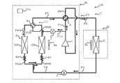
- FIG. 16 is a refrigerant circuit diagram of Modification Example 1 of the refrigeration cycle apparatus 100 according to the embodiment.
- the switching unit 8 is configured to be able to switch between the first state, the second state, and the third state.
- the switching unit 8t of the first modification includes a three-way valve 8a and a three-way valve 8b.
- the switching unit 8 t also has the same function as the switching unit 8.
- the bypass pipe P9Bt of the first modification is connected to the three-way valve 8a and the three-way valve 8b.
- the pipe P6At of the first modification connects the three-way valve 8a to the lower heat exchanger 5A, and the pipe P6Bt of the first modification connects the three-way valve 8b to the upper heat exchanger 5B.
- the three-way valve 8 a switches between a state A connecting the discharge side of the compressor 1 and the lower heat exchanger 5 A, and a state B connecting the lower heat exchanger 5 A and the flow path switching valve 9.
- the three-way valve 8 b switches between a state C connecting the discharge side of the compressor 1 and the upper heat exchanger 5 B and a state D connecting the upper heat exchanger 5 B and the flow path switching valve 9.
- the control device Cnt sets the three-way valve 8 a to the state B and sets the three-way valve 8 b to the state D.
- the control device Cnt sets the three-way valve 8 a to the state A and sets the three-way valve 8 b to the state D. Furthermore, in the second defrosting control, the control device Cnt sets the three-way valve 8 a to the state B and sets the three-way valve 8 b to the state C.
- This modification 1 also has the same effect as the refrigeration cycle apparatus 100 according to the embodiment.
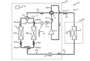
- FIG. 17 is a refrigerant circuit diagram of Modification 2 of the refrigeration cycle apparatus 100 according to the embodiment.
- the refrigeration cycle apparatus 100 according to the embodiment is configured to be able to switch between the heating operation and the cooling operation.
- the modification 2 does not have the flow path switching valve 9. For this reason, although the modification 2 can perform heating operation, it can not perform cooling operation.
- This modification 2 also has the same effect as the refrigeration cycle apparatus 100 according to the embodiment.
- FIG. 18 is a view schematically showing an outdoor heat exchanger 5t of Modification 3 of the refrigeration cycle apparatus 100 according to the embodiment.
- the volume of the lower heat exchanger 5A and the volume of the upper heat exchanger 5B are the same.
- the volume of the lower heat exchanger 5At is smaller than the volume of the upper heat exchanger 5Bt.
- the combined volume of the volume of the lower heat exchanger 5At and the volume of the upper heat exchanger 5Bt is the same as the volume of the volume of the lower heat exchanger 5A and the volume of the upper heat exchanger 5B. .
- the frost formation amount of the lower heat exchanger 5At at the start of the defrosting operation is the upper side at the start of the defrosting operation. It is smaller than the amount of frost formation of the heat exchanger 5Bt.
- the amount of heat supplied per unit time to the lower heat exchanger 5A in the first defrost control and the third defrost control is unit time to the lower heat exchanger 5A in the second defrost control. It is assumed that it is equivalent to the amount of heat supplied per unit.
- the amount of heat received by the unit heat of the lower heat exchanger 5At per unit time from the lower heat exchanger 5At is the upper heat exchange during the second defrosting control.
- the unit mass frost of the container 5Bt becomes larger than the amount of heat received from the upper heat exchanger 5Bt per unit time. That is, the defrosting efficiency of the third defrosting control is improved as compared to the defrosting efficiency of the second defrosting control. Since the amount of frost formation is increased by the second defrosting control in the lower heat exchanger 5At, the demand for improvement of the defrosting efficiency of the third defrosting control is high.
- the defrosting efficiency of the third defrosting control of the third modification is improved as described above, the amount of frost remaining in the lower heat exchanger 5A is suppressed at the end of the third defrosting control. Ru. Further, during the first defrosting control, the amount of heat received by the unit heat of the lower heat exchanger 5At per unit time from the heat of the lower heat exchanger 5At during the second defrosting control is the upper heat exchanger 5Bt. The unit mass frost is larger than the amount of heat received from the upper heat exchanger 5Bt per unit time. That is, the defrosting efficiency of the first defrosting control is also improved as compared with the defrosting efficiency of the second defrosting control.
- the amount of frost formation on the lower heat exchanger 5A is suppressed.
- the amount of frost remaining in the lower heat exchanger 5A is further suppressed.
Abstract
According to the present invention, when a control device performs defrost operations that melt the frost on an outdoor heat exchanger, the control device performs first defrost control that makes the switching state of a switching part a first state, then, after having performed the first defrost control, performs second defrost control that makes the switching state of the switching part a second state, and then, after having performed the second defrost control, performs third defrost control that makes the switching state of the switching part the first state.
Description
本発明は、冷凍サイクル装置に関し、特に、熱交換器に形成されている霜を溶かす除霜運転を実行する冷凍サイクル装置に関するものである。
The present invention relates to a refrigeration cycle apparatus, and more particularly to a refrigeration cycle apparatus that executes a defrosting operation for melting frost formed in a heat exchanger.
従来の冷凍サイクル装置には、暖房運転を行っているときに凝縮器として機能する室内熱交換器と、下側熱交換器及び上側熱交換器を有する室外熱交換器とを備えている冷凍サイクル装置が提案されている(例えば、特許文献1参照)。上側熱交換器は下側熱交換器の上に設けられている。ここで、特許文献1の冷凍サイクル装置が暖房運転を行っているときにおいて、下側熱交換器及び上側熱交換器が蒸発器として機能し、その結果、下側熱交換器及び上側熱交換器には霜が形成される。一般的に、熱交換器に形成された霜は、熱交換器の伝熱管を流れる冷媒と熱交換器を通過する空気との熱交換を阻害する。このため、特許文献1の冷凍サイクル装置は、室外熱交換器に霜が形成された場合に、室外熱交換器の霜を溶かす除霜運転を行う。
The conventional refrigeration cycle apparatus includes a refrigeration cycle including an indoor heat exchanger functioning as a condenser when performing a heating operation, and an outdoor heat exchanger having a lower heat exchanger and an upper heat exchanger. An apparatus has been proposed (see, for example, Patent Document 1). The upper heat exchanger is provided on the lower heat exchanger. Here, when the refrigeration cycle apparatus of Patent Document 1 is performing a heating operation, the lower heat exchanger and the upper heat exchanger function as an evaporator, and as a result, the lower heat exchanger and the upper heat exchanger There is frost on the surface. Generally, the frost formed in the heat exchanger inhibits the heat exchange between the refrigerant flowing through the heat transfer tubes of the heat exchanger and the air passing through the heat exchanger. Therefore, when the frost is formed on the outdoor heat exchanger, the refrigeration cycle apparatus of Patent Document 1 performs the defrosting operation to melt the frost of the outdoor heat exchanger.
特許文献1の冷凍サイクル装置の除霜運転は、室内熱交換器が凝縮器として機能し且つ上側熱交換器の除霜がなされる上除霜と、室内熱交換器が凝縮器として機能し且つ下側熱交換器の除霜がなされる下除霜とを有している。上除霜において下側熱交換器が蒸発器として機能し、下除霜において上側熱交換器が蒸発器として機能している。このように、上除霜及び下除霜において室内熱交換器は凝縮器として機能しているので、特許文献1の冷凍サイクル装置が除霜運転を行っているときでも、室内には室内機から暖気が供給される。
In the defrosting operation of the refrigeration cycle apparatus of Patent Document 1, upper defrosting in which the indoor heat exchanger functions as a condenser and defrosting of the upper heat exchanger is performed, and the indoor heat exchanger functions as a condenser, It has lower defrosting with which defrosting of a lower side heat exchanger is made. In the upper defrosting, the lower heat exchanger functions as an evaporator, and in the lower defrosting, the upper heat exchanger functions as an evaporator. As described above, since the indoor heat exchanger functions as a condenser in the upper defrosting and the lower defrosting, even when the refrigeration cycle apparatus of Patent Document 1 is performing the defrosting operation, it is possible to use the indoor unit indoors Warm air is supplied.
特許文献1の冷凍サイクル装置が上除霜を実行しているときにおいて、上側熱交換器で溶けた水は、上側熱交換器から下側熱交換器へ流れ落ちる。このとき、下側熱交換器は蒸発器として機能しているので、上側熱交換器から下側熱交換器へ流れ落ちた水が下側熱交換器で氷結してしまう。このため、下除霜の開始時における下側熱交換器の霜の厚みが、上除霜の開始時における下側熱交換器の霜の厚みよりも、増加してしまう場合がある。下側熱交換器に形成された霜が厚くなると、その分、熱源である下側熱交換器に接触していない霜の量が増加する。このため、下側熱交換器に形成された霜が厚くなると、下除霜時における下側熱交換器の除霜効率が低下する。したがって、特許文献1の冷凍サイクル装置は、下除霜の終了時において、下側熱交換器で溶け残る霜の量が増加してしまう場合がある。下側熱交換器で溶け残っている霜の量が増加すると、その分、下側熱交換器の伝熱管の冷媒と下側熱交換器を通過する空気との熱交換が阻害される。その結果、除霜運転の後に再開される暖房運転の効率が低下してしまう。
When the refrigeration cycle apparatus of Patent Document 1 performs the upper defrosting, the water melted in the upper heat exchanger flows from the upper heat exchanger to the lower heat exchanger. At this time, since the lower heat exchanger functions as an evaporator, the water that has flowed from the upper heat exchanger to the lower heat exchanger is frozen in the lower heat exchanger. For this reason, the thickness of the frost of the lower heat exchanger at the start of the lower defrost may be larger than the thickness of the frost of the lower heat exchanger at the start of the upper defrost. As the frost formed on the lower heat exchanger becomes thicker, the amount of frost not in contact with the lower heat exchanger, which is a heat source, increases accordingly. For this reason, if the frost formed on the lower heat exchanger becomes thick, the defrosting efficiency of the lower heat exchanger at the time of the lower defrosting is lowered. Therefore, in the refrigeration cycle apparatus of Patent Document 1, the amount of frost remaining in the lower heat exchanger may increase at the end of the lower defrosting. As the amount of frost remaining in the lower heat exchanger increases, heat exchange between the refrigerant in the heat transfer tubes of the lower heat exchanger and the air passing through the lower heat exchanger is impeded. As a result, the efficiency of the heating operation resumed after the defrosting operation is reduced.
本発明は、上記のような課題を解決するためになされたもので、暖房運転の効率の低下を抑制することができる冷凍サイクル装置を提供することを目的としている。
The present invention has been made to solve the problems as described above, and it is an object of the present invention to provide a refrigeration cycle apparatus capable of suppressing a decrease in the efficiency of heating operation.
本発明に係る冷凍サイクル装置は、圧縮機と、暖房運転時において凝縮器として機能する室内熱交換器と、下側熱交換器及び下側熱交換器の上側に設けられている上側熱交換器を有し、暖房運転時において蒸発器として機能する室外熱交換器と、暖房運転時において室内熱交換器よりも冷媒の流れ方向の下流側に設けられ、暖房運転時において室外熱交換器よりも冷媒流れ方向の上流側に設けられている減圧装置と、圧縮機の吐出側と下側熱交換器とを繋ぐ第1の状態と圧縮機の吐出側と上側熱交換器とを繋ぐ第2の状態とを切り替える切替部と、切替部の切替状態を制御する制御装置と、を備え、制御装置が室外熱交換器の霜を溶かす除霜運転を行う場合において、制御装置は、切替部の切替状態を第1の状態とする第1の除霜制御を実行し、第1の除霜制御を実行した後に、切替部の切替状態を第2の状態とする第2の除霜制御を実行し、第2の除霜制御を実行した後に、切替部の切替状態を第1の状態とする第3の除霜制御を実行する。
The refrigeration cycle apparatus according to the present invention includes a compressor, an indoor heat exchanger functioning as a condenser during heating operation, an upper heat exchanger provided above the lower heat exchanger and the lower heat exchanger. It has an outdoor heat exchanger that functions as an evaporator during heating operation, and is provided downstream of the indoor heat exchanger in the flow direction of the refrigerant during heating operation, and is more than the outdoor heat exchanger during heating operation. A pressure reducing device provided on the upstream side in the refrigerant flow direction, a first state connecting the discharge side of the compressor and the lower heat exchanger, and a second state connecting the discharge side of the compressor and the upper heat exchanger The control device includes a switching unit that switches between states and a control device that controls the switching state of the switching unit, and the control device performs switching of the switching unit when the control device performs a defrost operation that melts the frost of the outdoor heat exchanger. The first defrost control that sets the state to the first state is After the first defrosting control is performed, the second defrosting control is performed to set the switching state of the switching unit to the second state, and after the second defrosting control is performed, the switching of the switching unit is performed. A third defrost control is performed to set the state to the first state.
本発明に係る冷凍サイクル装置によれば、第2の除霜制御の実行の前に第1の除霜制御が実行されるので、第3の除霜制御の開始時における下側熱交換器の霜が厚くなることが抑制され、その結果、暖房運転の効率の低下が抑制される。
According to the refrigeration cycle apparatus of the present invention, since the first defrosting control is executed before the execution of the second defrosting control, the lower side heat exchanger at the start of the third defrosting control It is suppressed that a frost becomes thick, as a result, the fall of the efficiency of heating operation is suppressed.
実施の形態.
以下、図面を参照しながら実施の形態について説明する。なお、以下の図面では各構成部材の大きさの関係が実際のものとは異なる場合がある。明細書全文に表わされている構成要素の形態は、あくまでも例示であって、これらの記載に限定されるものではない。 Embodiment.
Hereinafter, embodiments will be described with reference to the drawings. In addition, in the following drawings, the relationship of the magnitude | size of each structural member may differ from an actual thing. The form of the component shown in the full text of the specification is just an example, and is not limited to these descriptions.
<実施の形態の構成>
図1は、実施の形態に係る冷凍サイクル装置100の概要構成図である。図2は、実施の形態に係る冷凍サイクル装置100の冷媒回路図である。図3は、室外熱交換器5を模式的に示した図である。図1に示すように、冷凍サイクル装置100は、室外熱交換器5を有する室外機20と、配管P2及び配管P3を介して室外機20に繋がっている室内機30とを備えている。実施の形態において、冷凍サイクル装置100は空気調和装置である。冷凍サイクル装置100は、室外熱交換器5が蒸発器として機能する暖房運転と、室外熱交換器5が凝縮器として機能する冷房運転と、暖房運転時において室外熱交換器5に形成された霜を溶かす除霜運転と、を行うことができる。 <Configuration of Embodiment>
FIG. 1 is a schematic configuration diagram of arefrigeration cycle apparatus 100 according to the embodiment. FIG. 2 is a refrigerant circuit diagram of the refrigeration cycle apparatus 100 according to the embodiment. FIG. 3 is a view schematically showing the outdoor heat exchanger 5. As shown in FIG. 1, the refrigeration cycle apparatus 100 includes an outdoor unit 20 having an outdoor heat exchanger 5 and an indoor unit 30 connected to the outdoor unit 20 via a pipe P2 and a pipe P3. In the embodiment, the refrigeration cycle apparatus 100 is an air conditioner. The refrigeration cycle apparatus 100 includes a heating operation in which the outdoor heat exchanger 5 functions as an evaporator, a cooling operation in which the outdoor heat exchanger 5 functions as a condenser, and a frost formed on the outdoor heat exchanger 5 during the heating operation. Defrosting operation, and can be performed.
図1は、実施の形態に係る冷凍サイクル装置100の概要構成図である。図2は、実施の形態に係る冷凍サイクル装置100の冷媒回路図である。図3は、室外熱交換器5を模式的に示した図である。図1に示すように、冷凍サイクル装置100は、室外熱交換器5を有する室外機20と、配管P2及び配管P3を介して室外機20に繋がっている室内機30とを備えている。実施の形態において、冷凍サイクル装置100は空気調和装置である。冷凍サイクル装置100は、室外熱交換器5が蒸発器として機能する暖房運転と、室外熱交換器5が凝縮器として機能する冷房運転と、暖房運転時において室外熱交換器5に形成された霜を溶かす除霜運転と、を行うことができる。 <Configuration of Embodiment>
FIG. 1 is a schematic configuration diagram of a
室外機20は、冷媒を圧縮する圧縮機1と、冷媒を減圧する減圧装置3と、暖房運転時において蒸発器として機能する室外熱交換器5と、室外熱交換器5に空気を供給する室外送風機5aと、圧縮機1の吐出側に設けられている流路切替弁9とを備えている。減圧装置3は、暖房運転時において室内熱交換器2よりも冷媒の流れ方向の下流側に設けられ、暖房運転時において室外熱交換器5よりも冷媒流れ方向の上流側に設けられている。また、図3に示すように、室外熱交換器5は、下側熱交換器5Aと、下側熱交換器5Aの上に設けられている上側熱交換器5Bとを有している。下側熱交換器5Aの体積と上側熱交換器5Bの体積とは同じである。下側熱交換器5Aは、板状のフィンFnAと、フィンFnAに設けられ、冷媒が流れる伝熱管hpAとを有している。また、上側熱交換器5Bは、板状のフィンFnBと、フィンFnBに設けられ、冷媒が流れる伝熱管hpBとを有している。また、室外機20は、下側熱交換器5Aに繋がっているキャピラリーチューブ4Aと、上側熱交換器5Bに繋がっているキャピラリーチューブ4Bとを備えている。また、室外機20は、室外熱交換器5に繋がっている切替部8と、開閉する弁7とを備えている。切替部8は、圧縮機1の吐出側と下側熱交換器5Aとを繋ぐ第1の状態と、圧縮機1の吐出側と上側熱交換器5Bとを繋ぐ第2の状態と、室外熱交換器5と流路切替弁9とを繋ぐ第3の状態とを切り替える弁である。更に、室外機20は、圧縮機1等の各種のアクチュエータを制御する制御装置Cntを備えている。室内機30は、暖房運転時において凝縮器として機能する室内熱交換器2と、室内熱交換器2に空気を供給する室内送風機2aとを備えている。
The outdoor unit 20 includes a compressor 1 for compressing a refrigerant, a decompression device 3 for decompressing a refrigerant, an outdoor heat exchanger 5 functioning as an evaporator during heating operation, and an outdoor unit for supplying air to the outdoor heat exchanger 5 A fan 5 a and a flow path switching valve 9 provided on the discharge side of the compressor 1 are provided. The pressure reducing device 3 is provided downstream of the indoor heat exchanger 2 in the flow direction of the refrigerant during the heating operation, and is provided upstream of the outdoor heat exchanger 5 in the flow direction of the refrigerant during the heating operation. Moreover, as shown in FIG. 3, the outdoor heat exchanger 5 has a lower heat exchanger 5A and an upper heat exchanger 5B provided on the lower heat exchanger 5A. The volume of the lower heat exchanger 5A and the volume of the upper heat exchanger 5B are the same. The lower heat exchanger 5A has a plate-like fin FnA and a heat transfer pipe hpA provided on the fin FnA and in which the refrigerant flows. Further, the upper heat exchanger 5B has a plate-like fin FnB and a heat transfer pipe hpB provided on the fin FnB and in which the refrigerant flows. The outdoor unit 20 also includes a capillary tube 4A connected to the lower heat exchanger 5A and a capillary tube 4B connected to the upper heat exchanger 5B. The outdoor unit 20 also includes a switching unit 8 connected to the outdoor heat exchanger 5 and a valve 7 that opens and closes. The switching unit 8 has a first state connecting the discharge side of the compressor 1 and the lower heat exchanger 5A, a second state connecting the discharge side of the compressor 1 and the upper heat exchanger 5B, and outdoor heat. This is a valve that switches between the third state in which the exchanger 5 and the flow path switching valve 9 are connected. Furthermore, the outdoor unit 20 includes a control device Cnt that controls various actuators such as the compressor 1 and the like. The indoor unit 30 includes an indoor heat exchanger 2 that functions as a condenser during heating operation, and an indoor fan 2a that supplies air to the indoor heat exchanger 2.
冷凍サイクル装置100は、圧縮機1、室内熱交換器2、減圧装置3及び室外熱交換器5を有する冷媒回路Cを備えている。冷媒回路Cは、圧縮機1、流路切替弁9、室内熱交換器2、減圧装置3、キャピラリーチューブ4A、キャピラリーチューブ4B、室外熱交換器5、切替部8を有する主回路C1と、弁7を有するバイパス回路C2とを備えている。バイパス回路C2は、主回路C1の構成のうち室内熱交換器2及び減圧装置3をバイパスしている。
The refrigeration cycle apparatus 100 includes a refrigerant circuit C including a compressor 1, an indoor heat exchanger 2, a pressure reducing device 3, and an outdoor heat exchanger 5. The refrigerant circuit C includes a compressor 1, a flow path switching valve 9, an indoor heat exchanger 2, a pressure reducing device 3, a capillary tube 4A, a capillary tube 4B, an outdoor heat exchanger 5, a main circuit C1 having a switching unit 8, and a valve And a bypass circuit C2. The bypass circuit C2 bypasses the indoor heat exchanger 2 and the pressure reducing device 3 in the configuration of the main circuit C1.
主回路C1は、圧縮機1の吐出側と流路切替弁9とを繋ぐ配管P1と、流路切替弁9と室内熱交換器2とを繋ぐ配管P2と、室内熱交換器2と減圧装置3とを繋ぐ配管P3と、暖房運転時の冷媒流れ方向において減圧装置3の下流側に繋がっている配管P4とを有している。また、主回路C1は、配管P4とキャピラリーチューブ4Aとを繋ぐ配管P5Aと、配管P4とキャピラリーチューブ4Bとを繋ぐ配管P5Bと、下側熱交換器5Aと切替部8とを繋ぐ配管P6Aと、上側熱交換器5Bと切替部8とを繋ぐ配管P6Bとを有している。更に、主回路C1は、切替部8と流路切替弁9とを繋ぐ配管P7と、流路切替弁9と圧縮機1の吸入側とを繋ぐ配管P8とを有している。バイパス回路C2は、配管P1と弁7とを繋ぐバイパス配管P9Aと、弁7と切替部8とを繋ぐバイパス配管P9Bとを有している。バイパス配管P9A及びバイパス配管P9Bが、圧縮機1の吐出側と切替部8とを繋げている。
The main circuit C1 includes a pipe P1 connecting the discharge side of the compressor 1 and the flow path switching valve 9, a pipe P2 connecting the flow path switching valve 9 and the indoor heat exchanger 2, an indoor heat exchanger 2 and a pressure reducing device And a pipe P4 connected to the downstream side of the pressure reducing device 3 in the refrigerant flow direction during the heating operation. The main circuit C1 also includes a pipe P5A connecting the pipe P4 and the capillary tube 4A, a pipe P5B connecting the pipe P4 and the capillary tube 4B, and a pipe P6A connecting the lower heat exchanger 5A and the switching unit 8; It has piping P6B which connects the upper side heat exchanger 5B and the switching part 8. As shown in FIG. Further, the main circuit C1 has a pipe P7 connecting the switching unit 8 and the flow path switching valve 9, and a pipe P8 connecting the flow path switching valve 9 and the suction side of the compressor 1. The bypass circuit C2 has a bypass pipe P9A connecting the pipe P1 and the valve 7 and a bypass pipe P9B connecting the valve 7 and the switching unit 8. The bypass pipe P9A and the bypass pipe P9B connect the discharge side of the compressor 1 and the switching unit 8.
図4は、実施の形態に係る冷凍サイクル装置100の制御機能のブロック図である。
制御装置Cntは、演算を行う演算部50Aと、アクチュエータを制御する制御部50Bと、データを記憶する記憶部50Cとを備えている。演算部50Aは、暖房運転等の各種運転を開始してから経過した時間と、予め定められている閾値とを比較する機能を有している。制御部50Bは、圧縮機1、減圧装置3、室内送風機2a、室外送風機5a、弁7、切替部8、及び流路切替弁9を制御する。記憶部50Cには、暖房運転から除霜運転へ移行するときに用いられる閾値等のデータが格納されている。 FIG. 4 is a block diagram of a control function of therefrigeration cycle apparatus 100 according to the embodiment.
The control device Cnt includes anoperation unit 50A that performs an operation, a control unit 50B that controls an actuator, and a storage unit 50C that stores data. The calculation unit 50A has a function of comparing the time elapsed since the start of various operations such as heating operation with a predetermined threshold. The control unit 50B controls the compressor 1, the pressure reducing device 3, the indoor blower 2a, the outdoor blower 5a, the valve 7, the switching unit 8, and the flow passage switching valve 9. The storage unit 50C stores data such as a threshold value used when shifting from the heating operation to the defrosting operation.
制御装置Cntは、演算を行う演算部50Aと、アクチュエータを制御する制御部50Bと、データを記憶する記憶部50Cとを備えている。演算部50Aは、暖房運転等の各種運転を開始してから経過した時間と、予め定められている閾値とを比較する機能を有している。制御部50Bは、圧縮機1、減圧装置3、室内送風機2a、室外送風機5a、弁7、切替部8、及び流路切替弁9を制御する。記憶部50Cには、暖房運転から除霜運転へ移行するときに用いられる閾値等のデータが格納されている。 FIG. 4 is a block diagram of a control function of the
The control device Cnt includes an
制御装置Cntに含まれる各機能部は、専用のハードウェア、又は、メモリに格納されるプログラムを実行するMPU(Micro Processing Unit)で構成される。制御装置Cntが専用のハードウェアである場合、制御装置Cntは、例えば、単一回路、複合回路、ASIC(application specific integrated circuit)、FPGA(field-programmable gate array)、またはこれらを組み合わせたものが該当する。制御装置Cntが実現する各機能部のそれぞれを、個別のハードウェアで実現してもよいし、各機能部を一つのハードウェアで実現してもよい。制御装置CntがMPUの場合、制御装置が実行する各機能は、ソフトウェア、ファームウェア、またはソフトウェアとファームウェアとの組み合わせにより実現される。ソフトウェアやファームウェアはプログラムとして記述され、記憶部50Cに格納される。MPUは、メモリに格納されたプログラムを読み出して実行することにより、制御装置Cntの各機能を実現する。記憶部50は、例えば、RAM、ROM、フラッシュメモリ、EPROM、EEPROM等の、不揮発性または揮発性の半導体メモリである。
Each functional unit included in the control device Cnt is configured by dedicated hardware or an MPU (Micro Processing Unit) that executes a program stored in a memory. When the controller Cnt is a dedicated hardware, the controller Cnt may be, for example, a single circuit, a composite circuit, an application specific integrated circuit (ASIC), a field-programmable gate array (FPGA), or a combination thereof. Applicable Each of the functional units realized by the control device Cnt may be realized by individual hardware, or each functional unit may be realized by one hardware. When the control device Cnt is an MPU, each function executed by the control device is realized by software, firmware, or a combination of software and firmware. The software and firmware are described as a program and stored in the storage unit 50C. The MPU implements each function of the control device Cnt by reading and executing a program stored in the memory. The storage unit 50 is, for example, a non-volatile or volatile semiconductor memory such as a RAM, a ROM, a flash memory, an EPROM, and an EEPROM.
<実施の形態の動作>
図5は、実施の形態に係る冷凍サイクル装置100の暖房運転の動作説明図である。図5において、切替部8の切替状態は第3の状態となっている。つまり、切替部8は、下側熱交換器5Aと流路切替弁9とを繋げるとともに、上側熱交換器5Bと流路切替弁9とを繋げている。また、図5において、流路切替弁9は、圧縮機1の吐出側と室内熱交換器2とを繋げるとともに、切替部8と圧縮機1の吸入側とを繋げている。また、図5において、弁7は閉じている。更に、図5において、室内送風機2a及び室外送風機5aは運転している。圧縮機1から吐出された冷媒は、流路切替弁9を通過した後に、室内熱交換器2に流入する。室内熱交換器2に流入した冷媒は液化する。室内熱交換器2から流出した冷媒は減圧装置3で減圧される。減圧装置3で減圧された冷媒は気液二相状態になっている。減圧装置3から流出した冷媒は室外熱交換器5に流入する。室外熱交換器5に流入した冷媒はガス化する。室外熱交換器5から流出した冷媒は、流路切替弁9を通過した後に、圧縮機1に戻る。 <Operation of Embodiment>
FIG. 5 is an operation explanatory view of the heating operation of therefrigeration cycle apparatus 100 according to the embodiment. In FIG. 5, the switching state of the switching unit 8 is the third state. That is, the switching unit 8 connects the lower heat exchanger 5A and the flow path switching valve 9 and connects the upper heat exchanger 5B and the flow path switching valve 9. Further, in FIG. 5, the flow path switching valve 9 connects the discharge side of the compressor 1 to the indoor heat exchanger 2 and connects the switching portion 8 to the suction side of the compressor 1. Also, in FIG. 5, the valve 7 is closed. Furthermore, in FIG. 5, the indoor blower 2a and the outdoor blower 5a are in operation. The refrigerant discharged from the compressor 1 flows into the indoor heat exchanger 2 after passing through the flow path switching valve 9. The refrigerant flowing into the indoor heat exchanger 2 is liquefied. The refrigerant flowing out of the indoor heat exchanger 2 is decompressed by the decompression device 3. The refrigerant decompressed by the decompression device 3 is in a gas-liquid two-phase state. The refrigerant flowing out of the pressure reducing device 3 flows into the outdoor heat exchanger 5. The refrigerant flowing into the outdoor heat exchanger 5 is gasified. The refrigerant that has flowed out of the outdoor heat exchanger 5 returns to the compressor 1 after passing through the flow path switching valve 9.
図5は、実施の形態に係る冷凍サイクル装置100の暖房運転の動作説明図である。図5において、切替部8の切替状態は第3の状態となっている。つまり、切替部8は、下側熱交換器5Aと流路切替弁9とを繋げるとともに、上側熱交換器5Bと流路切替弁9とを繋げている。また、図5において、流路切替弁9は、圧縮機1の吐出側と室内熱交換器2とを繋げるとともに、切替部8と圧縮機1の吸入側とを繋げている。また、図5において、弁7は閉じている。更に、図5において、室内送風機2a及び室外送風機5aは運転している。圧縮機1から吐出された冷媒は、流路切替弁9を通過した後に、室内熱交換器2に流入する。室内熱交換器2に流入した冷媒は液化する。室内熱交換器2から流出した冷媒は減圧装置3で減圧される。減圧装置3で減圧された冷媒は気液二相状態になっている。減圧装置3から流出した冷媒は室外熱交換器5に流入する。室外熱交換器5に流入した冷媒はガス化する。室外熱交換器5から流出した冷媒は、流路切替弁9を通過した後に、圧縮機1に戻る。 <Operation of Embodiment>
FIG. 5 is an operation explanatory view of the heating operation of the
図6は、実施の形態に係る冷凍サイクル装置100の冷房運転の動作説明図である。図6において、切替部8の切替状態は第3の状態となっている。また、図6において、流路切替弁9は、圧縮機1の吐出側と切替部8とを繋げるとともに、室内熱交換器2と圧縮機1の吸入側とを繋げている。また、図6において、弁7は閉じている。更に、図6において、室内送風機2a及び室外送風機5aは運転している。冷房運転時の冷媒の流れは、図5で説明した暖房運転時の冷媒の流れとは逆である。
FIG. 6 is an operation explanatory view of the cooling operation of the refrigeration cycle apparatus 100 according to the embodiment. In FIG. 6, the switching state of the switching unit 8 is the third state. Further, in FIG. 6, the flow path switching valve 9 connects the discharge side of the compressor 1 and the switching unit 8 and connects the indoor heat exchanger 2 and the suction side of the compressor 1. Also, in FIG. 6, the valve 7 is closed. Furthermore, in FIG. 6, the indoor blower 2a and the outdoor blower 5a are in operation. The flow of the refrigerant during the cooling operation is opposite to the flow of the refrigerant during the heating operation described with reference to FIG.
冷凍サイクル装置100が暖房運転を継続していると、室外熱交換器5の着霜量が増加する。これにより、室外熱交換器5において、空気と冷媒との熱交換の効率が低下する。そこで、冷凍サイクル装置100は、暖房運転を開始してから予め定められた時間が経過すると除霜運転を開始する。冷凍サイクル装置100の除霜運転の除霜方式は、圧縮機1から吐出されたホットガスを室外熱交換器5へ供給するホットガス除霜方式である。冷凍サイクル装置100の除霜運転は、下側熱交換器5Aの除霜をする第1の除霜制御と、第1の除霜制御の後に実行され、上側熱交換器5Bの除霜をする第2の除霜制御と、第2の除霜制御の後に実行され、下側熱交換器5Aの除霜をする第3の除霜制御とを有している。
When the refrigeration cycle apparatus 100 continues the heating operation, the amount of frost formation on the outdoor heat exchanger 5 increases. Thereby, in the outdoor heat exchanger 5, the efficiency of heat exchange between the air and the refrigerant is reduced. Therefore, the refrigeration cycle apparatus 100 starts the defrosting operation when a predetermined time passes after the heating operation is started. The defrosting method for the defrosting operation of the refrigeration cycle apparatus 100 is a hot gas defrosting method in which the hot gas discharged from the compressor 1 is supplied to the outdoor heat exchanger 5. The defrosting operation of the refrigeration cycle apparatus 100 is executed after the first defrosting control for defrosting the lower heat exchanger 5A and the first defrosting control to defrost the upper heat exchanger 5B. A second defrosting control and a third defrosting control that is executed after the second defrosting control to defrost the lower heat exchanger 5A are provided.
図7は、実施の形態に係る冷凍サイクル装置100の除霜運転の第1の除霜制御の動作説明図である。図7において、切替部8の切替状態は第1の状態となっている。つまり、切替部8は、圧縮機1の吐出側と下側熱交換器5Aとを繋げるとともに、上側熱交換器5Bと流路切替弁9とを繋げている。ここで、圧縮機1の吐出側と下側熱交換器5Aとは、配管P1、バイパス回路C2、切替部8、配管P6Aを介して繋がっている。また、上側熱交換器5Bと流路切替弁9とは、配管P6B、切替部8及び配管P7を介して繋がっている。また、図7において、流路切替弁9の状態は、図5で説明した暖房運転における流路切替弁9の状態と同じである。また、図7において、弁7は開いている。更に、図7において、室内送風機2a及び室外送風機5aは運転している。
FIG. 7 is an operation explanatory view of the first defrost control of the defrosting operation of the refrigeration cycle apparatus 100 according to the embodiment. In FIG. 7, the switching state of the switching unit 8 is in the first state. That is, the switching unit 8 connects the discharge side of the compressor 1 and the lower heat exchanger 5A, and connects the upper heat exchanger 5B and the flow path switching valve 9. Here, the discharge side of the compressor 1 and the lower heat exchanger 5A are connected via the pipe P1, the bypass circuit C2, the switching unit 8, and the pipe P6A. Further, the upper heat exchanger 5B and the flow path switching valve 9 are connected via the pipe P6B, the switching unit 8 and the pipe P7. Further, in FIG. 7, the state of the flow path switching valve 9 is the same as the state of the flow path switching valve 9 in the heating operation described with reference to FIG. 5. Also, in FIG. 7, the valve 7 is open. Furthermore, in FIG. 7, the indoor blower 2a and the outdoor blower 5a are in operation.
圧縮機1から吐出された冷媒の一部は、流路切替弁9を通過した後に、室内熱交換器2に流入する。室内熱交換器2に流入した冷媒は液化する。つまり、第1の除霜制御の実行時においても、室内熱交換器2は凝縮器として機能しているので、室内には室内機30から暖気が供給される。室内熱交換器2から流出した冷媒は減圧装置3で減圧される。減圧装置3で減圧された冷媒は気液二相状態になっている。
一方、圧縮機1から吐出された冷媒の他部、すなわちホットガスは、バイパス回路C2及び切替部8を介して下側熱交換器5Aに流入する。下側熱交換器5Aに流入したホットガスの熱は下側熱交換器5Aの霜に供給され、その結果、下側熱交換器5Aの霜が溶ける。下側熱交換器5Aから流出した冷媒は、減圧装置3で減圧された冷媒と合流する。
合流した冷媒は、上側熱交換器5Bに流入する。上側熱交換器5Bに流入した冷媒はガス化する。つまり、第1の除霜制御において上側熱交換器5Bは蒸発器として機能している。上側熱交換器5Bから流出した冷媒は、流路切替弁9を通過した後に、圧縮機1に戻る。 Part of the refrigerant discharged from thecompressor 1 flows into the indoor heat exchanger 2 after passing through the flow path switching valve 9. The refrigerant flowing into the indoor heat exchanger 2 is liquefied. That is, even when the first defrosting control is performed, the indoor heat exchanger 2 functions as a condenser, so warm air is supplied to the room from the indoor unit 30. The refrigerant flowing out of the indoor heat exchanger 2 is decompressed by the decompression device 3. The refrigerant decompressed by the decompression device 3 is in a gas-liquid two-phase state.
On the other hand, the other part of the refrigerant discharged from thecompressor 1, that is, the hot gas flows into the lower heat exchanger 5A via the bypass circuit C2 and the switching unit 8. The heat of the hot gas flowing into the lower heat exchanger 5A is supplied to the frost of the lower heat exchanger 5A, and as a result, the frost of the lower heat exchanger 5A is melted. The refrigerant flowing out of the lower heat exchanger 5A merges with the refrigerant decompressed by the decompression device 3.
The joined refrigerant flows into theupper heat exchanger 5B. The refrigerant flowing into the upper heat exchanger 5B is gasified. That is, in the first defrosting control, the upper heat exchanger 5B functions as an evaporator. The refrigerant flowing out of the upper heat exchanger 5B returns to the compressor 1 after passing through the flow path switching valve 9.
一方、圧縮機1から吐出された冷媒の他部、すなわちホットガスは、バイパス回路C2及び切替部8を介して下側熱交換器5Aに流入する。下側熱交換器5Aに流入したホットガスの熱は下側熱交換器5Aの霜に供給され、その結果、下側熱交換器5Aの霜が溶ける。下側熱交換器5Aから流出した冷媒は、減圧装置3で減圧された冷媒と合流する。
合流した冷媒は、上側熱交換器5Bに流入する。上側熱交換器5Bに流入した冷媒はガス化する。つまり、第1の除霜制御において上側熱交換器5Bは蒸発器として機能している。上側熱交換器5Bから流出した冷媒は、流路切替弁9を通過した後に、圧縮機1に戻る。 Part of the refrigerant discharged from the
On the other hand, the other part of the refrigerant discharged from the
The joined refrigerant flows into the
図8は、実施の形態に係る冷凍サイクル装置100の除霜運転の第2の除霜制御の動作説明図である。図8において、切替部8の切替状態は第2の状態となっている。つまり、切替部8は、圧縮機1の吐出側と上側熱交換器5Bとを繋げるとともに、下側熱交換器5Aと流路切替弁9とを繋げている。ここで、圧縮機1の吐出側と上側熱交換器5Bとは、配管P1、バイパス回路C2、切替部8、配管P6Bを介して繋がっている。また、下側熱交換器5Aと流路切替弁9とは、配管P6A、切替部8及び配管P7を介して繋がっている。また、図8において、流路切替弁9の状態は、図5で説明した暖房運転における流路切替弁9の状態と同じである。また、図8において、弁7は開いている。更に、図8において、室内送風機2a及び室外送風機5aは運転している。
FIG. 8 is an operation explanatory view of second defrosting control of the defrosting operation of the refrigeration cycle apparatus 100 according to the embodiment. In FIG. 8, the switching state of the switching unit 8 is in the second state. That is, the switching unit 8 connects the discharge side of the compressor 1 and the upper heat exchanger 5B, and connects the lower heat exchanger 5A and the flow path switching valve 9. Here, the discharge side of the compressor 1 and the upper heat exchanger 5B are connected via the pipe P1, the bypass circuit C2, the switching unit 8, and the pipe P6B. Further, the lower heat exchanger 5A and the flow path switching valve 9 are connected via the pipe P6A, the switching unit 8 and the pipe P7. Further, in FIG. 8, the state of the flow path switching valve 9 is the same as the state of the flow path switching valve 9 in the heating operation described in FIG. 5. Also, in FIG. 8, the valve 7 is open. Furthermore, in FIG. 8, the indoor blower 2a and the outdoor blower 5a are in operation.
圧縮機1から吐出された冷媒の一部は、流路切替弁9を通過した後に、室内熱交換器2に流入する。室内熱交換器2に流入した冷媒は液化する。つまり、第1の除霜制御と同様に第2の除霜制御の実行時においても、室内熱交換器2は凝縮器として機能しているので、室内には室内機30から暖気が供給される。室内熱交換器2から流出した冷媒は減圧装置3で減圧される。減圧装置3で減圧された冷媒は気液二相状態になっている。
一方、圧縮機1から吐出された冷媒の他部、すなわちホットガスは、バイパス回路C2及び切替部8を介して上側熱交換器5Bに流入する。上側熱交換器5Bに流入したホットガスの熱は上側熱交換器5Bの霜に供給され、その結果、上側熱交換器5Bの霜が溶ける。上側熱交換器5Bから流出した冷媒は、減圧装置3で減圧された冷媒と合流する。
合流した冷媒は、下側熱交換器5Aに流入する。下側熱交換器5Aに流入した冷媒はガス化する。つまり、第2の除霜制御において、下側熱交換器5Aは、蒸発器として機能している。下側熱交換器5Aから流出した冷媒は、流路切替弁9を通過した後に、圧縮機1に戻る。 Part of the refrigerant discharged from thecompressor 1 flows into the indoor heat exchanger 2 after passing through the flow path switching valve 9. The refrigerant flowing into the indoor heat exchanger 2 is liquefied. That is, even when the second defrosting control is performed as in the first defrosting control, the indoor heat exchanger 2 functions as a condenser, so warm air is supplied to the room from the indoor unit 30. . The refrigerant flowing out of the indoor heat exchanger 2 is decompressed by the decompression device 3. The refrigerant decompressed by the decompression device 3 is in a gas-liquid two-phase state.
On the other hand, the other part of the refrigerant discharged from thecompressor 1, that is, the hot gas flows into the upper heat exchanger 5B via the bypass circuit C2 and the switching unit 8. The heat of the hot gas flowing into the upper heat exchanger 5B is supplied to the frost of the upper heat exchanger 5B, and as a result, the frost of the upper heat exchanger 5B is melted. The refrigerant flowing out of the upper heat exchanger 5B merges with the refrigerant decompressed by the decompression device 3.
The joined refrigerant flows into thelower heat exchanger 5A. The refrigerant flowing into the lower heat exchanger 5A is gasified. That is, in the second defrosting control, the lower heat exchanger 5A functions as an evaporator. The refrigerant flowing out of the lower heat exchanger 5A returns to the compressor 1 after passing through the flow path switching valve 9.
一方、圧縮機1から吐出された冷媒の他部、すなわちホットガスは、バイパス回路C2及び切替部8を介して上側熱交換器5Bに流入する。上側熱交換器5Bに流入したホットガスの熱は上側熱交換器5Bの霜に供給され、その結果、上側熱交換器5Bの霜が溶ける。上側熱交換器5Bから流出した冷媒は、減圧装置3で減圧された冷媒と合流する。
合流した冷媒は、下側熱交換器5Aに流入する。下側熱交換器5Aに流入した冷媒はガス化する。つまり、第2の除霜制御において、下側熱交換器5Aは、蒸発器として機能している。下側熱交換器5Aから流出した冷媒は、流路切替弁9を通過した後に、圧縮機1に戻る。 Part of the refrigerant discharged from the
On the other hand, the other part of the refrigerant discharged from the
The joined refrigerant flows into the
図9は、実施の形態に係る冷凍サイクル装置100の除霜運転の第3の除霜制御の動作説明図である。図9に示す第3の除霜制御の動作状態は、図7に示す第1の除霜制御の動作状態と同じである。つまり、図9において、切替部8の切替状態は第1の状態となっている。つまり、第3の除霜制御における切替部8の切替状態は、第1の除霜制御における切替部8の切替状態と同じである。また、図9において、流路切替弁9の状態は、図5で説明した暖房運転における流路切替弁9の状態と同じである。また、図9において、弁7は開いている。更に、図9において、室内送風機2a及び室外送風機5aは運転している。第3の除霜制御の冷媒の流れは、第1の除霜制御の冷媒の流れと同様なので説明を割愛する。
FIG. 9 is an operation explanatory view of the third defrost control of the defrosting operation of the refrigeration cycle apparatus 100 according to the embodiment. The operation state of the third defrost control shown in FIG. 9 is the same as the operation state of the first defrost control shown in FIG. That is, in FIG. 9, the switching state of the switching unit 8 is in the first state. That is, the switching state of the switching unit 8 in the third defrosting control is the same as the switching state of the switching unit 8 in the first defrosting control. Further, in FIG. 9, the state of the flow path switching valve 9 is the same as the state of the flow path switching valve 9 in the heating operation described with reference to FIG. 5. Also, in FIG. 9, the valve 7 is open. Furthermore, in FIG. 9, the indoor blower 2a and the outdoor blower 5a are in operation. The flow of the refrigerant in the third defrosting control is the same as the flow of the refrigerant in the first defrosting control, and thus the description thereof will be omitted.
図10は、実施の形態に係る冷凍サイクル装置100の制御フローチャートである。
制御装置Cntは除霜運転に係る制御フローを開始する(ステップS0)。制御装置Cntは、暖房運転を開始してから経過した時間すなわち暖房運転時間htを取得する(ステップS1)。制御装置Cntの演算部50Aは、暖房運転時間htが予め定められている時間Thより長いか否かを判定する(ステップS2)。暖房運転時間htが予め定められている時間Thより長い場合には、制御装置Cntは除霜運転を開始する(ステップS3)。ステップS3において、制御装置Cntは第1の除霜制御を実行する。つまり、制御装置Cntは、切替部8の切替状態を第3の状態から第1の状態へ切り替え、且つ、弁7を開く。また、制御装置Cntは、流路切替弁9の状態を維持する。 FIG. 10 is a control flowchart of therefrigeration cycle apparatus 100 according to the embodiment.
Control device Cnt starts the control flow concerning defrosting operation (Step S0). The control device Cnt acquires the time elapsed since the start of the heating operation, that is, the heating operation time ht (step S1).Arithmetic unit 50A of control device Cnt determines whether heating operation time ht is longer than predetermined time Th (step S2). If the heating operation time ht is longer than the predetermined time Th, the control device Cnt starts the defrosting operation (step S3). In step S3, the control device Cnt executes the first defrosting control. That is, the control device Cnt switches the switching state of the switching unit 8 from the third state to the first state, and opens the valve 7. Further, the control device Cnt maintains the state of the flow path switching valve 9.
制御装置Cntは除霜運転に係る制御フローを開始する(ステップS0)。制御装置Cntは、暖房運転を開始してから経過した時間すなわち暖房運転時間htを取得する(ステップS1)。制御装置Cntの演算部50Aは、暖房運転時間htが予め定められている時間Thより長いか否かを判定する(ステップS2)。暖房運転時間htが予め定められている時間Thより長い場合には、制御装置Cntは除霜運転を開始する(ステップS3)。ステップS3において、制御装置Cntは第1の除霜制御を実行する。つまり、制御装置Cntは、切替部8の切替状態を第3の状態から第1の状態へ切り替え、且つ、弁7を開く。また、制御装置Cntは、流路切替弁9の状態を維持する。 FIG. 10 is a control flowchart of the
Control device Cnt starts the control flow concerning defrosting operation (Step S0). The control device Cnt acquires the time elapsed since the start of the heating operation, that is, the heating operation time ht (step S1).
制御装置Cntは、第1の除霜制御を開始してから経過した時間すなわち第1の除霜制御の実行時間t1を取得する(ステップS4)。制御装置Cntの演算部50Aは、実行時間t1が予め定められている時間T1より長いか否かを判定する(ステップS5)。実行時間t1が予め定められている時間T1より長い場合には、制御装置Cntは、第1の除霜制御を終了し、第2の除霜制御を開始する(ステップS6)。つまり、制御装置Cntは、切替部8の切替状態を第1の状態から第2の状態へ切り替える。また、制御装置Cntは、弁7を開のままとし、且つ、流路切替弁9の状態を維持する。
The control device Cnt acquires the time elapsed since the start of the first defrosting control, that is, the execution time t1 of the first defrosting control (step S4). Arithmetic unit 50A of control device Cnt determines whether or not execution time t1 is longer than predetermined time T1 (step S5). If the execution time t1 is longer than the predetermined time T1, the control device Cnt ends the first defrost control and starts the second defrost control (step S6). That is, the control device Cnt switches the switching state of the switching unit 8 from the first state to the second state. Further, the control device Cnt keeps the valve 7 open and maintains the state of the flow path switching valve 9.
制御装置Cntは、第2の除霜制御を開始してから経過した時間すなわち第2の除霜制御の実行時間t2を取得する(ステップS7)。制御装置Cntの演算部50Aは、実行時間t2が予め定められている時間T2より長いか否かを判定する(ステップS8)。ここで、時間T1は、時間T2よりも短い。つまり、第1の除霜制御の実行時間は、第2の除霜制御の実行時間よりも短くなっている。実行時間t2が予め定められている時間T2より長い場合には、制御装置Cntは、第2の除霜制御を終了し、第3の除霜制御を開始する(ステップS9)。つまり、制御装置Cntは、切替部8の切替状態を第2の状態から第1の状態へ切り替える。また、制御装置Cntは、弁7を開のままとし、且つ、流路切替弁9の状態を維持する。
The control device Cnt acquires the time elapsed since the start of the second defrosting control, that is, the execution time t2 of the second defrosting control (step S7). Arithmetic unit 50A of control device Cnt determines whether or not execution time t2 is longer than predetermined time T2 (step S8). Here, time T1 is shorter than time T2. That is, the execution time of the first defrosting control is shorter than the execution time of the second defrosting control. If the execution time t2 is longer than the predetermined time T2, the control device Cnt ends the second defrost control and starts the third defrost control (step S9). That is, the control device Cnt switches the switching state of the switching unit 8 from the second state to the first state. Further, the control device Cnt keeps the valve 7 open and maintains the state of the flow path switching valve 9.
制御装置Cntは、第3の除霜制御を開始してから経過した時間すなわち第3の除霜制御の実行時間t3を取得する(ステップS10)。制御装置Cntの演算部50Aは、実行時間t3が予め定められている時間T3より長いか否かを判定する(ステップS11)。ここで、時間T1は、時間T3よりも短い。つまり、第1の除霜制御の実行時間は、第3の除霜制御の実行時間よりも短くなっている。実行時間t3が予め定められている時間T3より長い場合には、制御装置Cntは、第3の除霜制御を終了する(ステップS12)。ステップS12において、制御装置Cntは除霜運転を終了し、暖房運転を再開する。つまり、制御装置Cntは、切替部8の切替状態を第1の状態から第3の状態へ切り替え、且つ、弁7を閉とする。また、制御装置Cntは、流路切替弁9の状態を維持する。制御装置Cntは除霜運転に係る制御フローを終了する(ステップS13)。
The control device Cnt acquires the time elapsed since the start of the third defrosting control, that is, the execution time t3 of the third defrosting control (step S10). Arithmetic unit 50A of control device Cnt determines whether or not execution time t3 is longer than predetermined time T3 (step S11). Here, time T1 is shorter than time T3. That is, the execution time of the first defrosting control is shorter than the execution time of the third defrosting control. If the execution time t3 is longer than the predetermined time T3, the control device Cnt ends the third defrosting control (step S12). In step S12, the control device Cnt ends the defrosting operation and resumes the heating operation. That is, the control device Cnt switches the switching state of the switching unit 8 from the first state to the third state, and closes the valve 7. Further, the control device Cnt maintains the state of the flow path switching valve 9. The control device Cnt ends the control flow relating to the defrosting operation (step S13).
図11は、暖房運転時において、下側熱交換器5Aに形成された霜Fr1及び上側熱交換器5Bに形成された霜Fr2の様子を示す模式図である。図11に示すように、暖房運転を継続していると、下側熱交換器5Aには霜Fr1が形成され、上側熱交換器5Bには霜Fr2が形成される。なお、説明の便宜上、下側熱交換器5Aの体積と上側熱交換器5Bの体積とは同じであるので、霜Fr1の量と霜Fr2の量が同じであるとする。
FIG. 11 is a schematic view showing the state of the frost Fr1 formed in the lower heat exchanger 5A and the frost Fr2 formed in the upper heat exchanger 5B during the heating operation. As shown in FIG. 11, when the heating operation is continued, the frost Fr1 is formed on the lower heat exchanger 5A, and the frost Fr2 is formed on the upper heat exchanger 5B. For convenience of explanation, since the volume of the lower heat exchanger 5A and the volume of the upper heat exchanger 5B are the same, it is assumed that the amount of the frost Fr1 and the amount of the frost Fr2 are the same.
図12は、第1の除霜制御を実行しているときにおいて、下側熱交換器5Aの霜Fr1aが溶ける様子を示す模式図である。第1の除霜制御を実行することで、霜Fr1が溶け、水draが下に流れ落ちる。霜Fr1の量が少なければ霜Fr1が完全に溶ける可能性があるが、ここでの説明では、霜Fr1が溶け残るものとする。つまり、第1の除霜制御を実行することで、霜Fr1の一部が溶ける。
FIG. 12 is a schematic diagram showing how the frost Fr1a of the lower heat exchanger 5A melts when the first defrosting control is being performed. By performing the first defrosting control, the frost Fr1 melts and the water dra flows downward. There is a possibility that the frost Fr1 may be completely melted if the amount of the frost Fr1 is small, but in the description herein, it is assumed that the frost Fr1 remains to be melted. That is, by performing the first defrosting control, part of the frost Fr1 is melted.
図13は、第2の除霜制御を実行しているときにおいて、上側熱交換器5Bの霜Fr2bが溶ける様子及び下側熱交換器5Aで水drbが再氷結する様子を示す模式図である。第2の除霜制御を実行することで、図12に示す霜Fr2が溶け、霜Fr2bになる。図12に示す霜Fr2が溶けると、水drbが上側熱交換器5Bから下側熱交換器5Aに流れ落ちる。流れ落ちた水drbは、蒸発器として機能している下側熱交換器5Aと下側熱交換器5Aに溶け残る霜とに冷却される。
FIG. 13 is a schematic diagram showing how the frost Fr2b of the upper heat exchanger 5B melts and how the water drb refreezes in the lower heat exchanger 5A when the second defrosting control is being performed. . By executing the second defrosting control, the frost Fr2 shown in FIG. 12 melts and becomes a frost Fr2b. When the frost Fr2 shown in FIG. 12 melts, the water drb flows from the upper heat exchanger 5B to the lower heat exchanger 5A. The drained water drb is cooled to the lower heat exchanger 5A functioning as an evaporator and the frost remaining in the lower heat exchanger 5A.
図14は、第2の除霜制御を終えたときにおいて、下側熱交換器5Aに残っている霜Fr1cの様子を示す模式図である。第2の除霜制御の実行時間は、第1の除霜制御の実行時間よりも長い。このため、第2の除霜制御を実行することで溶かすことができる霜量は、第1の除霜制御を実行することで溶かすことができる霜量よりも多くなる。図14において、図13に示す霜Fr2bは完全に溶けている。一方、図13に示す水drbは、下側熱交換器5Aの表面で氷結する、又は、下側熱交換器5Aに形成されている霜で氷結する。特に、水drbが下側熱交換器5Aに形成されている霜で氷結すると、下側熱交換器5Aの霜が厚くなり、熱源である下側熱交換器5Aに接触していない霜の量が増加する。しかし、第2の除霜制御の前に第1の除霜制御が実行されているので、第3の除霜運転の開始時における下側熱交換器5Aの霜は、厚くなることが抑制されている。
FIG. 14 is a schematic view showing the state of the frost Fr1c remaining in the lower heat exchanger 5A when the second defrosting control is finished. The execution time of the second defrost control is longer than the execution time of the first defrost control. Therefore, the amount of frost that can be melted by executing the second defrosting control is larger than the amount of frost that can be melted by executing the first defrosting control. In FIG. 14, the frost Fr2b shown in FIG. 13 is completely melted. On the other hand, the water drb shown in FIG. 13 freezes on the surface of the lower heat exchanger 5A or freezes due to the frost formed on the lower heat exchanger 5A. In particular, when the water drb freezes with the frost formed on the lower heat exchanger 5A, the frost of the lower heat exchanger 5A becomes thick and the amount of frost not in contact with the lower heat exchanger 5A as a heat source Will increase. However, since the first defrosting control is executed before the second defrosting control, thickening of the frost on the lower heat exchanger 5A at the start of the third defrosting operation is suppressed. ing.
図15は、第3の除霜制御を終えたときの室外熱交換器5を示す模式図である。上述のように、第3の除霜運転の開始時における下側熱交換器5Aの霜は、厚くなることが抑制されている。このため、第3の除霜制御を実行することで、図14に示す霜Fr1cが溶ける。
FIG. 15 is a schematic view showing the outdoor heat exchanger 5 when the third defrosting control is finished. As described above, the frost on the lower heat exchanger 5A at the start of the third defrosting operation is suppressed from being thickened. For this reason, the frost Fr1c shown in FIG. 14 is melted by executing the third defrosting control.
<実施の形態の効果>
従来の冷凍サイクル装置は、上側熱交換器の除霜を行い、その後、下側熱交換器の除霜を行う。つまり、従来の冷凍サイクル装置の室外熱交換器の除霜は、上側熱交換器の除霜及び下側熱交換器の除霜とを含む2段階の除霜である。従来の冷凍サイクル装置の除霜運転において、上側熱交換器の除霜が行われると、上側熱交換器から流れ落ちた水が下側熱交換器の霜に接触し、上側熱交換器から流れ落ちた水が下側熱交換器の霜で氷結する。その結果、下側熱交換器の除霜の開始時における下側熱交換器の霜の厚みは、上側熱交換器の除霜の開始時における下側熱交換器の霜の厚みよりも、厚くなってしまう。ここで、下側熱交換器に接触している霜は下側熱交換器から直に熱を受け取るので下側熱交換器に接触している霜は溶けやすい。その一方、下側熱交換器に接触していない霜例えば下側熱交換器の霜の外側部は、下側熱交換器に接触している霜等を介して伝わった熱を受け取る。このため、下側熱交換器の霜の外側部は溶けにくい。下側熱交換器の霜の厚みが厚くなる程、下側熱交換器に接触していない霜の量が増加することになるので、下側熱交換器の霜の厚みが厚くなる程、下側熱交換器の除霜効率が低下する可能性が高まる。しかし、冷凍サイクル装置100の制御装置Cntは、第2の除霜制御を実行する前に第1の除霜制御を実行する。このため、第3の除霜制御の開始時における下側熱交換器5Aの霜の厚みの増加が抑制され、その結果、第3の除霜制御時における下側熱交換器5Aの除霜効率の低下が抑制される。したがって、第3の除霜制御の終了時において、下側熱交換器5Aで溶け残る霜の量が抑制される。そして、制御装置Cntは第3の除霜制御を実行した後、暖房運転を再開する。第3の除霜制御の終了時において下側熱交換器5Aで溶け残る霜の量が抑制されているので、再開された暖房運転を実行しているときにおいて下側熱交換器5Aの伝熱管hpAの冷媒と下側熱交換器5Aを通過する空気との熱交換の阻害が抑制される。よって、除霜運転の後に再開される暖房運転を実行しているときにおいて下側熱交換器5Aの熱交換効率の低下が抑制され、その結果、冷凍サイクル装置100の暖房運転の効率の低下が抑制される。 <Effect of the embodiment>
The conventional refrigeration cycle apparatus performs defrosting of the upper heat exchanger and then performs defrosting of the lower heat exchanger. That is, the defrosting of the outdoor heat exchanger of the conventional refrigeration cycle apparatus is a two-stage defrosting including the defrosting of the upper heat exchanger and the defrosting of the lower heat exchanger. In the defrosting operation of the conventional refrigeration cycle apparatus, when defrosting of the upper heat exchanger is performed, the water that has fallen from the upper heat exchanger comes in contact with the frost of the lower heat exchanger and flows from the upper heat exchanger Water freezes in the frost on the lower heat exchanger. As a result, the thickness of the frost of the lower heat exchanger at the start of defrosting of the lower heat exchanger is thicker than the thickness of the frost of the lower heat exchanger at the start of defrosting of the upper heat exchanger. turn into. Here, since the frost in contact with the lower heat exchanger receives heat directly from the lower heat exchanger, the frost in contact with the lower heat exchanger is easily melted. On the other hand, the frost which is not in contact with the lower heat exchanger, for example, the outer part of the frost of the lower heat exchanger receives the heat conducted via the frost or the like in contact with the lower heat exchanger. For this reason, the frost outside of the lower heat exchanger is less likely to melt. As the thickness of the frost on the lower heat exchanger becomes thicker, the amount of frost not in contact with the lower heat exchanger increases, so the thickness of the frost on the lower heat exchanger becomes thicker. The possibility of decreasing the defrosting efficiency of the side heat exchanger is increased. However, the control device Cnt of therefrigeration cycle apparatus 100 executes the first defrost control before executing the second defrost control. For this reason, the increase in the thickness of the frost of lower side heat exchanger 5A at the time of the start of the third defrosting control is suppressed, and as a result, the defrosting efficiency of lower side heat exchanger 5A at the time of the third defrosting control The decrease in Therefore, at the end of the third defrosting control, the amount of frost remaining in the lower heat exchanger 5A is suppressed. Then, after executing the third defrosting control, the control device Cnt restarts the heating operation. Since the amount of frost remaining in the lower heat exchanger 5A at the end of the third defrosting control is suppressed, the heat transfer pipe of the lower heat exchanger 5A is performed when the restarted heating operation is being performed. The inhibition of heat exchange between the hpA refrigerant and the air passing through the lower heat exchanger 5A is suppressed. Therefore, when performing the heating operation resumed after the defrosting operation, the reduction of the heat exchange efficiency of the lower heat exchanger 5A is suppressed, and as a result, the reduction of the heating operation of the refrigeration cycle apparatus 100 Be suppressed.
従来の冷凍サイクル装置は、上側熱交換器の除霜を行い、その後、下側熱交換器の除霜を行う。つまり、従来の冷凍サイクル装置の室外熱交換器の除霜は、上側熱交換器の除霜及び下側熱交換器の除霜とを含む2段階の除霜である。従来の冷凍サイクル装置の除霜運転において、上側熱交換器の除霜が行われると、上側熱交換器から流れ落ちた水が下側熱交換器の霜に接触し、上側熱交換器から流れ落ちた水が下側熱交換器の霜で氷結する。その結果、下側熱交換器の除霜の開始時における下側熱交換器の霜の厚みは、上側熱交換器の除霜の開始時における下側熱交換器の霜の厚みよりも、厚くなってしまう。ここで、下側熱交換器に接触している霜は下側熱交換器から直に熱を受け取るので下側熱交換器に接触している霜は溶けやすい。その一方、下側熱交換器に接触していない霜例えば下側熱交換器の霜の外側部は、下側熱交換器に接触している霜等を介して伝わった熱を受け取る。このため、下側熱交換器の霜の外側部は溶けにくい。下側熱交換器の霜の厚みが厚くなる程、下側熱交換器に接触していない霜の量が増加することになるので、下側熱交換器の霜の厚みが厚くなる程、下側熱交換器の除霜効率が低下する可能性が高まる。しかし、冷凍サイクル装置100の制御装置Cntは、第2の除霜制御を実行する前に第1の除霜制御を実行する。このため、第3の除霜制御の開始時における下側熱交換器5Aの霜の厚みの増加が抑制され、その結果、第3の除霜制御時における下側熱交換器5Aの除霜効率の低下が抑制される。したがって、第3の除霜制御の終了時において、下側熱交換器5Aで溶け残る霜の量が抑制される。そして、制御装置Cntは第3の除霜制御を実行した後、暖房運転を再開する。第3の除霜制御の終了時において下側熱交換器5Aで溶け残る霜の量が抑制されているので、再開された暖房運転を実行しているときにおいて下側熱交換器5Aの伝熱管hpAの冷媒と下側熱交換器5Aを通過する空気との熱交換の阻害が抑制される。よって、除霜運転の後に再開される暖房運転を実行しているときにおいて下側熱交換器5Aの熱交換効率の低下が抑制され、その結果、冷凍サイクル装置100の暖房運転の効率の低下が抑制される。 <Effect of the embodiment>
The conventional refrigeration cycle apparatus performs defrosting of the upper heat exchanger and then performs defrosting of the lower heat exchanger. That is, the defrosting of the outdoor heat exchanger of the conventional refrigeration cycle apparatus is a two-stage defrosting including the defrosting of the upper heat exchanger and the defrosting of the lower heat exchanger. In the defrosting operation of the conventional refrigeration cycle apparatus, when defrosting of the upper heat exchanger is performed, the water that has fallen from the upper heat exchanger comes in contact with the frost of the lower heat exchanger and flows from the upper heat exchanger Water freezes in the frost on the lower heat exchanger. As a result, the thickness of the frost of the lower heat exchanger at the start of defrosting of the lower heat exchanger is thicker than the thickness of the frost of the lower heat exchanger at the start of defrosting of the upper heat exchanger. turn into. Here, since the frost in contact with the lower heat exchanger receives heat directly from the lower heat exchanger, the frost in contact with the lower heat exchanger is easily melted. On the other hand, the frost which is not in contact with the lower heat exchanger, for example, the outer part of the frost of the lower heat exchanger receives the heat conducted via the frost or the like in contact with the lower heat exchanger. For this reason, the frost outside of the lower heat exchanger is less likely to melt. As the thickness of the frost on the lower heat exchanger becomes thicker, the amount of frost not in contact with the lower heat exchanger increases, so the thickness of the frost on the lower heat exchanger becomes thicker. The possibility of decreasing the defrosting efficiency of the side heat exchanger is increased. However, the control device Cnt of the
一例を挙げて上述の効果の補足をする。第1の除霜制御の実行時間と第3の除霜制御の実行時間とを合わせた時間をX時間とし、第2の除霜制御の実行時間をY時間とする。また、従来の冷凍サイクル装置の下側熱交換器の除霜時間をX時間とし、従来の冷凍サイクル装置の上側熱交換器の除霜時間をY時間とする。このように、冷凍サイクル装置100の除霜時間と従来の冷凍サイクル装置の除霜時間とが同じである場合には、冷凍サイクル装置100の下側熱交換器5Aで溶け残る霜の量は、従来の冷凍サイクル装置の下側熱交換器で溶け残る霜の量よりも、抑制されている。上述したように、冷凍サイクル装置100の制御装置Cntが第2の除霜制御を実行する前に第1の除霜制御を実行するので、第3の除霜制御の開始時における下側熱交換器5Aの霜が厚くなることが抑制され、その結果、第3の除霜制御時における下側熱交換器5Aの除霜効率の低下が抑制されるためである。
Take an example to supplement the above effects. The time obtained by combining the execution time of the first defrost control and the execution time of the third defrost control is X, and the execution time of the second defrost control is Y. Further, the defrosting time of the lower heat exchanger of the conventional refrigeration cycle apparatus is X time, and the defrosting time of the upper heat exchanger of the conventional refrigeration cycle apparatus is Y time. Thus, when the defrosting time of the refrigeration cycle apparatus 100 and the defrosting time of the conventional refrigeration cycle apparatus are the same, the amount of frost remaining in the lower heat exchanger 5A of the refrigeration cycle apparatus 100 is The amount of frost remaining in the lower heat exchanger of the conventional refrigeration cycle apparatus is suppressed. As described above, since the controller Cnt of the refrigeration cycle apparatus 100 executes the first defrost control before executing the second defrost control, the lower heat exchange at the start of the third defrost control It is because it is suppressed that the frost of container 5A becomes thick, as a result, the fall of the defrost efficiency of lower side heat exchanger 5A at the time of the 3rd defrost control is controlled.
実施の形態において、冷凍サイクル装置100の第3の除霜制御の実行時間は、予め定められている。しかし、上述のように、第3の除霜制御の開始時における下側熱交換器5Aの霜が厚くなることが抑制されているので、冷凍サイクル装置100の管理者は、下側熱交換器5Aの霜の溶け残りを懸念して、第3の除霜制御の実行時間を必要以上に長く設定しなくてもよい。つまり、冷凍サイクル装置100は、除霜運転時間を短く設定しやすい構成である。ここで、除霜運転時間を短くすることができると、その分、除霜運転から暖房運転に復帰するタイミングの遅れも抑制される。このため、冷凍サイクル装置100は、暖房運転の時間及び除霜運転の時間を含む総運転時間に対する暖房運転の時間の割合が、小さくなることが抑制されている。したがって、冷凍サイクル装置100は、室内温度の低下の抑制効果を有する。
In the embodiment, the execution time of the third defrosting control of the refrigeration cycle apparatus 100 is predetermined. However, as described above, since the thickening of the frost on the lower heat exchanger 5A at the start of the third defrosting control is suppressed, the administrator of the refrigeration cycle apparatus 100 determines that the lower heat exchanger It is not necessary to set the execution time of the third defrosting control longer than necessary due to the remaining unmelted frost of 5A. That is, the refrigeration cycle apparatus 100 is configured to easily set the defrosting operation time short. Here, if the defrosting operation time can be shortened, a delay in the timing of returning from the defrosting operation to the heating operation is also suppressed. Therefore, in the refrigeration cycle apparatus 100, the ratio of the heating operation time to the total operation time including the heating operation time and the defrosting operation time is suppressed to be small. Therefore, the refrigeration cycle apparatus 100 has the effect of suppressing the decrease in the indoor temperature.
冷凍サイクル装置100が除霜運転を行っている場合において、室内熱交換器2は凝縮器として機能している。具体的には、制御装置Cntが第1の除霜制御、第2の除霜制御及び第3の除霜制御を実行している場合において、室内熱交換器2は凝縮器として機能している。このため、冷凍サイクル装置100は、室外機20で室外熱交換器5の除霜を行いながら、室内機30による室内の暖房を行うことができる。
When the refrigeration cycle apparatus 100 is performing a defrosting operation, the indoor heat exchanger 2 functions as a condenser. Specifically, when the control device Cnt is executing the first defrost control, the second defrost control, and the third defrost control, the indoor heat exchanger 2 functions as a condenser. . Therefore, the refrigeration cycle apparatus 100 can perform indoor heating by the indoor unit 30 while performing defrosting of the outdoor heat exchanger 5 by the outdoor unit 20.
ここでは、説明の便宜上、第3の除霜制御の実行時間が第1の除霜制御の実行時間よりも短い場合も、第1の除霜制御の実行時間が第3の除霜制御の実行時間よりも短い場合も、第1の除霜制御の実行時間と第3の除霜制御の実行時間とを合わせた総時間が一定であるとする。第3の除霜制御の実行時間が第1の除霜制御の実行時間よりも短い場合においては、第1の除霜制御の実行時間が長い分、第1の除霜制御において下側熱交換器5Aで溶ける霜の量が増加する。ここで、第2の除霜制御の実行により、下側熱交換器5Aの着霜量が増加してしまう。このため、第3の除霜制御の実行時間が第1の除霜制御の実行時間よりも短い場合においては、第3の除霜制御の実行時間が短くなる分、第3の除霜制御の終了時において下側熱交換器5Aの霜が溶け残りやすくなる。そこで、冷凍サイクル装置100において、第1の除霜制御の実行時間は、第3の除霜制御の実行時間よりも短くなっている。換言すれば、冷凍サイクル装置100において、第3の除霜制御の実行時間は、第1の除霜制御の実行時間よりも長くなっている。このため、第2の除霜制御の実行により、下側熱交換器5Aの着霜量が増加したとしても、第3の除霜制御の終了時において下側熱交換器5Aの霜が溶け残りにくくなる。つまり、第3の除霜制御の実行時間が第1の除霜制御の実行時間よりも長いので、冷凍サイクル装置100は、第3の除霜制御の終了時において下側熱交換器5Aの霜が溶け残りにくくなる効果を有している。
ここで、上側熱交換器5Bの着霜量が大きくなる程、第2の除霜制御時において、上側熱交換器5Bから下側熱交換器5Aへ流れ落ちる水の量は増加する。このため、上側熱交換器5Bの着霜量が大きくなる程、第3の除霜制御の開始時における下側熱交換器5Aの着霜量は増加しやすい。このため、上側熱交換器5Bの着霜量が大きくなると、上述した、第3の除霜制御の終了時において下側熱交換器5Aの霜が溶け残りにくくなる効果はより顕著となる。 Here, for convenience of explanation, even when the execution time of the third defrosting control is shorter than the execution time of the first defrosting control, the execution time of the first defrosting control is the execution of the third defrosting control Even if the time is shorter than the time, it is assumed that the total time obtained by combining the execution time of the first defrost control and the execution time of the third defrost control is constant. When the execution time of the third defrosting control is shorter than the execution time of the first defrosting control, the lower heat exchange in the first defrosting control is performed because the execution time of the first defrosting control is longer. The amount of frost melted in thevessel 5A increases. Here, the amount of frost formation of lower side heat exchanger 5A will increase by execution of the 2nd defrost control. For this reason, in the case where the execution time of the third defrost control is shorter than the execution time of the first defrost control, the third defrost control execution time is shorter than the execution time of the third defrost control. At the end time, the frost of the lower heat exchanger 5A tends to be left undissolved. Therefore, in the refrigeration cycle apparatus 100, the execution time of the first defrosting control is shorter than the execution time of the third defrosting control. In other words, in the refrigeration cycle apparatus 100, the execution time of the third defrosting control is longer than the execution time of the first defrosting control. Therefore, even if the amount of frost formation on the lower heat exchanger 5A is increased by execution of the second defrost control, the frost on the lower heat exchanger 5A remains undissolved at the end of the third defrost control. It becomes difficult. That is, since the execution time of the third defrosting control is longer than the execution time of the first defrosting control, the refrigeration cycle apparatus 100 generates the frost on the lower heat exchanger 5A at the end of the third defrosting control. Has the effect of making it difficult to melt.
Here, the amount of water flowing from theupper heat exchanger 5B to the lower heat exchanger 5A increases during the second defrosting control as the frost formation amount of the upper heat exchanger 5B increases. Therefore, as the frost formation amount of the upper heat exchanger 5B becomes larger, the frost formation amount of the lower heat exchanger 5A at the start of the third defrosting control tends to increase. For this reason, when the frost formation amount of the upper heat exchanger 5B becomes large, the effect that the frost of the lower heat exchanger 5A becomes difficult to remain undissolved at the end of the third defrosting control becomes more remarkable.
ここで、上側熱交換器5Bの着霜量が大きくなる程、第2の除霜制御時において、上側熱交換器5Bから下側熱交換器5Aへ流れ落ちる水の量は増加する。このため、上側熱交換器5Bの着霜量が大きくなる程、第3の除霜制御の開始時における下側熱交換器5Aの着霜量は増加しやすい。このため、上側熱交換器5Bの着霜量が大きくなると、上述した、第3の除霜制御の終了時において下側熱交換器5Aの霜が溶け残りにくくなる効果はより顕著となる。 Here, for convenience of explanation, even when the execution time of the third defrosting control is shorter than the execution time of the first defrosting control, the execution time of the first defrosting control is the execution of the third defrosting control Even if the time is shorter than the time, it is assumed that the total time obtained by combining the execution time of the first defrost control and the execution time of the third defrost control is constant. When the execution time of the third defrosting control is shorter than the execution time of the first defrosting control, the lower heat exchange in the first defrosting control is performed because the execution time of the first defrosting control is longer. The amount of frost melted in the
Here, the amount of water flowing from the
第1の除霜制御の実行時間を長く設定しすぎると、下側熱交換器5Aの霜が完全に溶けたにもかかわらず、下側熱交換器5Aの除霜が行われることになる。つまり、第1の除霜制御の実行時間を長く設定しすぎると、第1の除霜制御の実行時間のうち、霜を溶かしていない時間すなわち無駄な時間の割合が増えてしまう。そこで、冷凍サイクル装置100において、第1の除霜制御の実行時間は、第2の除霜制御の実行期間よりも短くなっている。このように、第1の除霜制御の実行時間が抑えられているので、冷凍サイクル装置100は、第1の除霜制御の実行時間のうち霜を溶かしていない時間の割合が増えることが抑制される効果を有する。
If the execution time of the first defrosting control is set too long, the defrosting of the lower heat exchanger 5A will be performed even though the frost of the lower heat exchanger 5A is completely melted. That is, if the execution time of the first defrost control is set too long, the proportion of the time in which the frost is not melted, that is, the useless time increases among the execution times of the first defrost control. Therefore, in the refrigeration cycle apparatus 100, the execution time of the first defrosting control is shorter than the execution period of the second defrosting control. As described above, since the execution time of the first defrost control is suppressed, the refrigeration cycle apparatus 100 suppresses the increase in the ratio of the time during which the frost is not melted in the execution time of the first defrost control. Have an effect.
制御装置Cntは、暖房運転を開始してから予め定められた時間が経過した場合には、除霜運転を開始する。つまり、冷凍サイクル装置100は、除霜運転を開始するか否かの判定に用いる温度センサが不要となっている。このため、冷凍サイクル装置100の製造コストは抑制されている。
The control device Cnt starts the defrosting operation when a predetermined time has elapsed since the heating operation was started. That is, the refrigeration cycle apparatus 100 does not require the temperature sensor used to determine whether to start the defrosting operation. For this reason, the manufacturing cost of the refrigeration cycle apparatus 100 is suppressed.
冷凍サイクル装置100は、切替部8、バイパス配管P9A、バイパス配管P9B及び弁7を有している。そして、制御装置Cntは、暖房運転において弁7を閉とする。これにより、暖房運転において、バイパス回路C2にはホットガスが供給されず、室内熱交換器2にはホットガスが供給される。その結果、室内熱交換器2は凝縮器として機能し、室外熱交換器5は蒸発器として機能する。また、制御装置Cntは、除霜運転において切替部8の切替状態を第1の状態又は第2の状態とするとともに弁7を開とする。これにより、除霜運転において、バイパス回路C2及び室内熱交換器2にはホットガスが供給される。その結果、室内熱交換器2は凝縮器として機能し、下側熱交換器5A及び上側熱交換器5Bのうちの一方は除霜され、下側熱交換器5A及び上側熱交換器5Bのうちの他方は蒸発器として機能する。
The refrigeration cycle apparatus 100 includes a switching unit 8, a bypass pipe P9A, a bypass pipe P9B, and a valve 7. Then, the control device Cnt closes the valve 7 in the heating operation. Thus, in the heating operation, the hot gas is not supplied to the bypass circuit C2, and the hot gas is supplied to the indoor heat exchanger 2. As a result, the indoor heat exchanger 2 functions as a condenser, and the outdoor heat exchanger 5 functions as an evaporator. Further, the control device Cnt sets the switching state of the switching unit 8 in the first state or the second state and opens the valve 7 in the defrosting operation. Thus, in the defrosting operation, the hot gas is supplied to the bypass circuit C2 and the indoor heat exchanger 2. As a result, the indoor heat exchanger 2 functions as a condenser, and one of the lower heat exchanger 5A and the upper heat exchanger 5B is defrosted, and the lower heat exchanger 5A and the upper heat exchanger 5B are defrosted. The other functions as an evaporator.
<実施の形態の変形例1>
図16は、実施の形態に係る冷凍サイクル装置100の変形例1の冷媒回路図である。切替部8は、第1の状態と第2の状態と第3の状態とを切り替えることができる構成であった。変形例1の切替部8tは、三方弁8aと三方弁8bとを備えている。切替部8tも、切替部8と同様の機能を有している。また、変形例1のバイパス配管P9Btは、三方弁8a及び三方弁8bに繋がっている。また、変形例1の配管P6Atは、三方弁8aと下側熱交換器5Aとを繋いでおり、変形例1の配管P6Btは、三方弁8bと上側熱交換器5Bとを繋いでいる。 <Modification 1 of Embodiment>
FIG. 16 is a refrigerant circuit diagram of Modification Example 1 of therefrigeration cycle apparatus 100 according to the embodiment. The switching unit 8 is configured to be able to switch between the first state, the second state, and the third state. The switching unit 8t of the first modification includes a three-way valve 8a and a three-way valve 8b. The switching unit 8 t also has the same function as the switching unit 8. The bypass pipe P9Bt of the first modification is connected to the three-way valve 8a and the three-way valve 8b. The pipe P6At of the first modification connects the three-way valve 8a to the lower heat exchanger 5A, and the pipe P6Bt of the first modification connects the three-way valve 8b to the upper heat exchanger 5B.
図16は、実施の形態に係る冷凍サイクル装置100の変形例1の冷媒回路図である。切替部8は、第1の状態と第2の状態と第3の状態とを切り替えることができる構成であった。変形例1の切替部8tは、三方弁8aと三方弁8bとを備えている。切替部8tも、切替部8と同様の機能を有している。また、変形例1のバイパス配管P9Btは、三方弁8a及び三方弁8bに繋がっている。また、変形例1の配管P6Atは、三方弁8aと下側熱交換器5Aとを繋いでおり、変形例1の配管P6Btは、三方弁8bと上側熱交換器5Bとを繋いでいる。 <
FIG. 16 is a refrigerant circuit diagram of Modification Example 1 of the
三方弁8aは、圧縮機1の吐出側と下側熱交換器5Aとを繋ぐ状態Aと、下側熱交換器5Aと流路切替弁9とを繋ぐ状態Bとを切り替える。また、三方弁8bは、圧縮機1の吐出側と上側熱交換器5Bとを繋ぐ状態Cと、上側熱交換器5Bと流路切替弁9とを繋ぐ状態Dとを切り替える。暖房運転及び冷房運転において、制御装置Cntは、三方弁8aを状態Bとし、三方弁8bを状態Dとする。また、第1の除霜制御及び第3の除霜制御において、制御装置Cntは、三方弁8aを状態Aとし、三方弁8bを状態Dとする。更に、第2の除霜制御において、制御装置Cntは、三方弁8aを状態Bとし、三方弁8bを状態Cとする。この変形例1も、実施の形態に係る冷凍サイクル装置100と同様の効果を有する。
The three-way valve 8 a switches between a state A connecting the discharge side of the compressor 1 and the lower heat exchanger 5 A, and a state B connecting the lower heat exchanger 5 A and the flow path switching valve 9. The three-way valve 8 b switches between a state C connecting the discharge side of the compressor 1 and the upper heat exchanger 5 B and a state D connecting the upper heat exchanger 5 B and the flow path switching valve 9. In the heating operation and the cooling operation, the control device Cnt sets the three-way valve 8 a to the state B and sets the three-way valve 8 b to the state D. Further, in the first defrost control and the third defrost control, the control device Cnt sets the three-way valve 8 a to the state A and sets the three-way valve 8 b to the state D. Furthermore, in the second defrosting control, the control device Cnt sets the three-way valve 8 a to the state B and sets the three-way valve 8 b to the state C. This modification 1 also has the same effect as the refrigeration cycle apparatus 100 according to the embodiment.
<実施の形態の変形例2>
図17は、実施の形態に係る冷凍サイクル装置100の変形例2の冷媒回路図である。実施の形態の冷凍サイクル装置100は暖房運転と冷房運転とを切り替えることができる構成であった。変形例2は流路切替弁9を有していない。このため、変形例2は、暖房運転を行うことができるが、冷房運転を行うことができない。この変形例2も、実施の形態に係る冷凍サイクル装置100と同様の効果を有する。 <Modification 2 of Embodiment>
FIG. 17 is a refrigerant circuit diagram ofModification 2 of the refrigeration cycle apparatus 100 according to the embodiment. The refrigeration cycle apparatus 100 according to the embodiment is configured to be able to switch between the heating operation and the cooling operation. The modification 2 does not have the flow path switching valve 9. For this reason, although the modification 2 can perform heating operation, it can not perform cooling operation. This modification 2 also has the same effect as the refrigeration cycle apparatus 100 according to the embodiment.
図17は、実施の形態に係る冷凍サイクル装置100の変形例2の冷媒回路図である。実施の形態の冷凍サイクル装置100は暖房運転と冷房運転とを切り替えることができる構成であった。変形例2は流路切替弁9を有していない。このため、変形例2は、暖房運転を行うことができるが、冷房運転を行うことができない。この変形例2も、実施の形態に係る冷凍サイクル装置100と同様の効果を有する。 <
FIG. 17 is a refrigerant circuit diagram of
<実施の形態の変形例3>
図18は、実施の形態に係る冷凍サイクル装置100の変形例3の室外熱交換器5tを模式的に示した図である。実施の形態の冷凍サイクル装置100において、下側熱交換器5Aの体積と上側熱交換器5Bの体積とは同じであった。変形例3において、下側熱交換器5Atの体積は、上側熱交換器5Btの体積よりも小さくなっている。なお、下側熱交換器5Atの体積と上側熱交換器5Btの体積とを合わせた体積は、下側熱交換器5Aの体積と上側熱交換器5Bの体積とを合わせた体積と同じである。 <Modification 3 of Embodiment>
FIG. 18 is a view schematically showing an outdoor heat exchanger 5t of Modification 3 of therefrigeration cycle apparatus 100 according to the embodiment. In the refrigeration cycle apparatus 100 of the embodiment, the volume of the lower heat exchanger 5A and the volume of the upper heat exchanger 5B are the same. In the third modification, the volume of the lower heat exchanger 5At is smaller than the volume of the upper heat exchanger 5Bt. The combined volume of the volume of the lower heat exchanger 5At and the volume of the upper heat exchanger 5Bt is the same as the volume of the volume of the lower heat exchanger 5A and the volume of the upper heat exchanger 5B. .
図18は、実施の形態に係る冷凍サイクル装置100の変形例3の室外熱交換器5tを模式的に示した図である。実施の形態の冷凍サイクル装置100において、下側熱交換器5Aの体積と上側熱交換器5Bの体積とは同じであった。変形例3において、下側熱交換器5Atの体積は、上側熱交換器5Btの体積よりも小さくなっている。なお、下側熱交換器5Atの体積と上側熱交換器5Btの体積とを合わせた体積は、下側熱交換器5Aの体積と上側熱交換器5Bの体積とを合わせた体積と同じである。 <Modification 3 of Embodiment>
FIG. 18 is a view schematically showing an outdoor heat exchanger 5t of Modification 3 of the
下側熱交換器5Atの体積が上側熱交換器5Btの体積よりも小さいので、除霜運転を開始するときにおける下側熱交換器5Atの着霜量は、除霜運転を開始するときにおける上側熱交換器5Btの着霜量よりも少なくなっている。ここで、第1の除霜制御及び第3の除霜制御において下側熱交換器5Aに単位時間あたりに供給される熱量が、第2の除霜制御において下側熱交換器5Aに単位時間あたりに供給される熱量と同等であるとする。この場合において、第3の除霜制御中において下側熱交換器5Atの単位質量の霜が下側熱交換器5Atから単位時間あたりに受け取る熱量は、第2の除霜制御中において上側熱交換器5Btの単位質量の霜が上側熱交換器5Btから単位時間あたりに受け取る熱量よりも大きくなる。つまり、第3の除霜制御の除霜効率が、第2の除霜制御の除霜効率と比較して向上する。下側熱交換器5Atは第2の除霜制御によって着霜量が増加するので、第3の除霜制御の除霜効率の向上の要請は高い。変形例3の第3の除霜制御の除霜効率は上述の通り向上しているので、第3の除霜制御の終了時において、下側熱交換器5Aで溶け残る霜の量が抑制される。
また、第1の除霜制御中において下側熱交換器5Atの単位質量の霜が下側熱交換器5Atから単位時間あたりに受け取る熱量は、第2の除霜制御中において上側熱交換器5Btの単位質量の霜が上側熱交換器5Btから単位時間あたりに受け取る熱量よりも大きくなる。つまり、第1の除霜制御の除霜効率も、第2の除霜制御の除霜効率と比較して向上する。その結果、第3の除霜制御の開始時において、下側熱交換器5Aの着霜量が抑制される。これにより、第3の除霜制御の終了時において、下側熱交換器5Aで溶け残る霜の量が更に抑制される。 Since the volume of the lower heat exchanger 5At is smaller than the volume of the upper heat exchanger 5Bt, the frost formation amount of the lower heat exchanger 5At at the start of the defrosting operation is the upper side at the start of the defrosting operation. It is smaller than the amount of frost formation of the heat exchanger 5Bt. Here, the amount of heat supplied per unit time to thelower heat exchanger 5A in the first defrost control and the third defrost control is unit time to the lower heat exchanger 5A in the second defrost control. It is assumed that it is equivalent to the amount of heat supplied per unit. In this case, during the third defrosting control, the amount of heat received by the unit heat of the lower heat exchanger 5At per unit time from the lower heat exchanger 5At is the upper heat exchange during the second defrosting control. The unit mass frost of the container 5Bt becomes larger than the amount of heat received from the upper heat exchanger 5Bt per unit time. That is, the defrosting efficiency of the third defrosting control is improved as compared to the defrosting efficiency of the second defrosting control. Since the amount of frost formation is increased by the second defrosting control in the lower heat exchanger 5At, the demand for improvement of the defrosting efficiency of the third defrosting control is high. Since the defrosting efficiency of the third defrosting control of the third modification is improved as described above, the amount of frost remaining in the lower heat exchanger 5A is suppressed at the end of the third defrosting control. Ru.
Further, during the first defrosting control, the amount of heat received by the unit heat of the lower heat exchanger 5At per unit time from the heat of the lower heat exchanger 5At during the second defrosting control is the upper heat exchanger 5Bt. The unit mass frost is larger than the amount of heat received from the upper heat exchanger 5Bt per unit time. That is, the defrosting efficiency of the first defrosting control is also improved as compared with the defrosting efficiency of the second defrosting control. As a result, at the start of the third defrosting control, the amount of frost formation on thelower heat exchanger 5A is suppressed. Thereby, at the end of the third defrosting control, the amount of frost remaining in the lower heat exchanger 5A is further suppressed.
また、第1の除霜制御中において下側熱交換器5Atの単位質量の霜が下側熱交換器5Atから単位時間あたりに受け取る熱量は、第2の除霜制御中において上側熱交換器5Btの単位質量の霜が上側熱交換器5Btから単位時間あたりに受け取る熱量よりも大きくなる。つまり、第1の除霜制御の除霜効率も、第2の除霜制御の除霜効率と比較して向上する。その結果、第3の除霜制御の開始時において、下側熱交換器5Aの着霜量が抑制される。これにより、第3の除霜制御の終了時において、下側熱交換器5Aで溶け残る霜の量が更に抑制される。 Since the volume of the lower heat exchanger 5At is smaller than the volume of the upper heat exchanger 5Bt, the frost formation amount of the lower heat exchanger 5At at the start of the defrosting operation is the upper side at the start of the defrosting operation. It is smaller than the amount of frost formation of the heat exchanger 5Bt. Here, the amount of heat supplied per unit time to the
Further, during the first defrosting control, the amount of heat received by the unit heat of the lower heat exchanger 5At per unit time from the heat of the lower heat exchanger 5At during the second defrosting control is the upper heat exchanger 5Bt. The unit mass frost is larger than the amount of heat received from the upper heat exchanger 5Bt per unit time. That is, the defrosting efficiency of the first defrosting control is also improved as compared with the defrosting efficiency of the second defrosting control. As a result, at the start of the third defrosting control, the amount of frost formation on the
1 圧縮機、2 室内熱交換器、2a 室内送風機、3 減圧装置、4A キャピラリーチューブ、4B キャピラリーチューブ、5 室外熱交換器、5A 下側熱交換器、5At 下側熱交換器、5B 上側熱交換器、5Bt 上側熱交換器、5a 室外送風機、5t 室外熱交換器、7 弁、8 切替部、8a 三方弁、8b 三方弁、8t 切替部、9 流路切替弁、20 室外機、30 室内機、50 記憶部、50A 演算部、50B 制御部、50C 記憶部、100 冷凍サイクル装置、C 冷媒回路、C1 主回路、C2 バイパス回路、Cnt 制御装置、FnA フィン、FnB フィン、P1 配管、P2 配管、P3 配管、P4 配管、P5A 配管、P5B 配管、P6A 配管、P6At 配管、P6B 配管、P6Bt 配管、P7 配管、P8 配管、P9A バイパス配管、P9B バイパス配管、P9Bt バイパス配管、hpA 伝熱管、hpB 伝熱管。
Reference Signs List 1 compressor, 2 indoor heat exchanger, 2a indoor blower, 3 decompression device, 4A capillary tube, 4B capillary tube, 5 outdoor heat exchanger, 5A lower heat exchanger, 5At lower heat exchanger, 5B upper heat exchange , 5 Bt upper heat exchanger, 5 a outdoor fan, 5 t outdoor heat exchanger, 7 valve, 8 switching unit, 8 a three-way valve, 8 b three-way valve, 8 t switching unit, 9 flow switching valve, 20 outdoor unit, 30 indoor unit , 50 storage unit, 50A operation unit, 50B control unit, 50C storage unit, 100 refrigeration cycle device, C refrigerant circuit, C1 main circuit, C2 bypass circuit, Cnt control device, FnA fin, FnB fin, P1 piping, P2 piping, P3 piping, P4 piping, P5A piping, P5B piping, P6A piping, P6At piping, P6B Tube, P6Bt piping, P7 piping, P8 piping, P9A bypass pipe, P9B bypass pipe, P9Bt bypass pipe, hpA heat transfer tube, hpB heat transfer tube.
Claims (7)
- 圧縮機と、
暖房運転時において凝縮器として機能する室内熱交換器と、
下側熱交換器及び下側熱交換器の上側に設けられている上側熱交換器を有し、前記暖房運転時において蒸発器として機能する室外熱交換器と、
前記暖房運転時において前記室内熱交換器よりも冷媒の流れ方向の下流側に設けられ、前記暖房運転時において前記室外熱交換器よりも冷媒流れ方向の上流側に設けられている減圧装置と、
前記圧縮機の吐出側と前記下側熱交換器とを繋ぐ第1の状態と前記圧縮機の吐出側と前記上側熱交換器とを繋ぐ第2の状態とを切り替える切替部と、
前記切替部の切替状態を制御する制御装置と、
を備え、
前記制御装置が前記室外熱交換器の霜を溶かす除霜運転を行う場合において、
前記制御装置は、
前記切替部の前記切替状態を前記第1の状態とする第1の除霜制御を実行し、
前記第1の除霜制御を実行した後に、前記切替部の前記切替状態を前記第2の状態とする第2の除霜制御を実行し、
前記第2の除霜制御を実行した後に、前記切替部の前記切替状態を前記第1の状態とする第3の除霜制御を実行する
冷凍サイクル装置。 A compressor,
An indoor heat exchanger that functions as a condenser during heating operation;
An outdoor heat exchanger having an upper heat exchanger provided above the lower heat exchanger and the lower heat exchanger, and functioning as an evaporator during the heating operation;
A pressure reducing device provided downstream of the indoor heat exchanger in the flow direction of the refrigerant during the heating operation, and provided upstream of the outdoor heat exchanger in the flow direction of the refrigerant during the heating operation;
A switching unit that switches between a first state connecting the discharge side of the compressor and the lower heat exchanger, and a second state connecting the discharge side of the compressor and the upper heat exchanger;
A control device that controls the switching state of the switching unit;
Equipped with
In the case where the control device performs a defrosting operation to melt the frost of the outdoor heat exchanger,
The controller is
Executing a first defrosting control to make the switching state of the switching unit the first state;
After executing the first defrosting control, a second defrosting control is performed in which the switching state of the switching unit is set to the second state,
A refrigeration cycle apparatus that executes third defrosting control that changes the switching state of the switching unit to the first state after executing the second defrosting control. - 前記第1の除霜制御及び前記第3の除霜制御において、前記室内熱交換器は凝縮器として機能し且つ前記上側熱交換器は蒸発器として機能しており、
前記第2の除霜制御において、前記室内熱交換器は凝縮器として機能し且つ前記下側熱交換器が蒸発器として機能している
請求項1に記載の冷凍サイクル装置。 In the first defrosting control and the third defrosting control, the indoor heat exchanger functions as a condenser and the upper heat exchanger functions as an evaporator.
The refrigeration cycle apparatus according to claim 1, wherein in the second defrosting control, the indoor heat exchanger functions as a condenser and the lower heat exchanger functions as an evaporator. - 前記第1の除霜制御の実行時間は、前記第3の除霜制御の実行時間よりも短い
請求項1又は2に記載の冷凍サイクル装置。 The refrigeration cycle apparatus according to claim 1, wherein an execution time of the first defrosting control is shorter than an execution time of the third defrosting control. - 前記第1の除霜制御の実行時間は、前記第2の除霜制御の実行時間よりも短い
請求項1~3のいずれか一項に記載の冷凍サイクル装置。 The refrigeration cycle apparatus according to any one of claims 1 to 3, wherein an execution time of the first defrosting control is shorter than an execution time of the second defrosting control. - 前記制御装置は、前記暖房運転を開始してから予め定められた時間が経過した場合には、前記除霜運転を開始する
請求項1~4のいずれか一項に記載の冷凍サイクル装置。 The refrigeration cycle apparatus according to any one of claims 1 to 4, wherein the control device starts the defrosting operation when a predetermined time has elapsed since the heating operation was started. - 前記圧縮機の吐出側と前記切替部とを繋ぐバイパス配管と、
前記バイパス配管に設けられている弁とを更に備え、
前記制御装置は、前記暖房運転において前記弁を閉とし、前記除霜運転において前記弁を開とする
請求項1~5のいずれか一項に記載の冷凍サイクル装置。 Bypass piping that connects the discharge side of the compressor and the switching unit;
And a valve provided in the bypass pipe,
The refrigeration cycle apparatus according to any one of claims 1 to 5, wherein the control device closes the valve in the heating operation and opens the valve in the defrosting operation. - 前記下側熱交換器の体積は、前記上側熱交換器の体積よりも小さい
請求項1~6のいずれか一項に記載の冷凍サイクル装置。 The refrigeration cycle apparatus according to any one of claims 1 to 6, wherein a volume of the lower heat exchanger is smaller than a volume of the upper heat exchanger.
Priority Applications (6)
| Application Number | Priority Date | Filing Date | Title |
|---|---|---|---|
| JP2019567492A JP6899927B2 (en) | 2018-01-26 | 2018-01-26 | Air conditioner |
| PCT/JP2018/002475 WO2019146071A1 (en) | 2018-01-26 | 2018-01-26 | Refrigeration cycle device |
| EP18902790.7A EP3745053A4 (en) | 2018-01-26 | 2018-01-26 | Refrigeration cycle device |
| CN201880086512.0A CN111630330B (en) | 2018-01-26 | 2018-01-26 | Air conditioning apparatus |
| RU2020127718A RU2742855C1 (en) | 2018-01-26 | 2018-01-26 | Air conditioning device |
| US16/961,005 US11927381B2 (en) | 2018-01-26 | 2018-01-26 | Air-conditioning apparatus |
Applications Claiming Priority (1)
| Application Number | Priority Date | Filing Date | Title |
|---|---|---|---|
| PCT/JP2018/002475 WO2019146071A1 (en) | 2018-01-26 | 2018-01-26 | Refrigeration cycle device |
Publications (1)
| Publication Number | Publication Date |
|---|---|
| WO2019146071A1 true WO2019146071A1 (en) | 2019-08-01 |
Family
ID=67394897
Family Applications (1)
| Application Number | Title | Priority Date | Filing Date |
|---|---|---|---|
| PCT/JP2018/002475 WO2019146071A1 (en) | 2018-01-26 | 2018-01-26 | Refrigeration cycle device |
Country Status (6)
| Country | Link |
|---|---|
| US (1) | US11927381B2 (en) |
| EP (1) | EP3745053A4 (en) |
| JP (1) | JP6899927B2 (en) |
| CN (1) | CN111630330B (en) |
| RU (1) | RU2742855C1 (en) |
| WO (1) | WO2019146071A1 (en) |
Families Citing this family (1)
| Publication number | Priority date | Publication date | Assignee | Title |
|---|---|---|---|---|
| CN112984897B (en) * | 2021-02-08 | 2022-10-25 | 青岛海尔生物医疗股份有限公司 | Refrigerator and humidity control method for refrigerator |
Citations (4)
| Publication number | Priority date | Publication date | Assignee | Title |
|---|---|---|---|---|
| JPH0914816A (en) * | 1995-06-23 | 1997-01-17 | Sharp Corp | Defrosting device for evaporator in cold heat keeping device |
| JPH1089817A (en) * | 1996-08-31 | 1998-04-10 | Lg Electron Inc | Frosting preventing device for heat pump |
| JP4272224B2 (en) | 2006-09-07 | 2009-06-03 | 日立アプライアンス株式会社 | Air conditioner |
| JP2009133578A (en) * | 2007-11-30 | 2009-06-18 | Daikin Ind Ltd | Refrigerating device |
Family Cites Families (15)
| Publication number | Priority date | Publication date | Assignee | Title |
|---|---|---|---|---|
| US4313313A (en) * | 1980-01-17 | 1982-02-02 | Carrier Corporation | Apparatus and method for defrosting a heat exchanger of a refrigeration circuit |
| GB2167543B (en) * | 1984-11-26 | 1988-09-21 | Sanden Corp | Refrigerated display cabinet |
| KR0129641Y1 (en) * | 1995-03-30 | 1999-01-15 | 김광호 | Indoor machine of an airconditioner |
| US5771699A (en) * | 1996-10-02 | 1998-06-30 | Ponder; Henderson F. | Three coil electric heat pump |
| US6244057B1 (en) * | 1998-09-08 | 2001-06-12 | Hitachi, Ltd. | Air conditioner |
| KR20100081621A (en) * | 2009-01-06 | 2010-07-15 | 엘지전자 주식회사 | Air conditioner and defrosting driving method of the same |
| JP2012013363A (en) * | 2010-07-02 | 2012-01-19 | Panasonic Corp | Air conditioner |
| BR112013032198B1 (en) * | 2011-06-13 | 2021-11-03 | Fred Lingelbach | EVAPORATOR AND CONDENSER SYSTEM (CES) AND METHOD OF OPERATION |
| WO2013038438A1 (en) * | 2011-09-13 | 2013-03-21 | 三菱電機株式会社 | Refrigeration and air-conditioning device |
| SE537022C2 (en) * | 2012-12-21 | 2014-12-09 | Fläkt Woods AB | Process and apparatus for defrosting an evaporator wide air handling unit |
| JP6688555B2 (en) * | 2013-11-25 | 2020-04-28 | 三星電子株式会社Samsung Electronics Co.,Ltd. | Air conditioner |
| WO2015129080A1 (en) * | 2014-02-27 | 2015-09-03 | 三菱電機株式会社 | Heat source side unit and refrigeration cycle device |
| JP6201872B2 (en) * | 2014-04-16 | 2017-09-27 | 三菱電機株式会社 | Air conditioner |
| WO2016166801A1 (en) * | 2015-04-13 | 2016-10-20 | 三菱電機株式会社 | Air conditioning device |
| JP6642247B2 (en) * | 2016-04-28 | 2020-02-05 | 株式会社デンソー | Refrigeration cycle device |
-
2018
- 2018-01-26 US US16/961,005 patent/US11927381B2/en active Active
- 2018-01-26 RU RU2020127718A patent/RU2742855C1/en active
- 2018-01-26 EP EP18902790.7A patent/EP3745053A4/en active Pending
- 2018-01-26 WO PCT/JP2018/002475 patent/WO2019146071A1/en unknown
- 2018-01-26 JP JP2019567492A patent/JP6899927B2/en active Active
- 2018-01-26 CN CN201880086512.0A patent/CN111630330B/en active Active
Patent Citations (4)
| Publication number | Priority date | Publication date | Assignee | Title |
|---|---|---|---|---|
| JPH0914816A (en) * | 1995-06-23 | 1997-01-17 | Sharp Corp | Defrosting device for evaporator in cold heat keeping device |
| JPH1089817A (en) * | 1996-08-31 | 1998-04-10 | Lg Electron Inc | Frosting preventing device for heat pump |
| JP4272224B2 (en) | 2006-09-07 | 2009-06-03 | 日立アプライアンス株式会社 | Air conditioner |
| JP2009133578A (en) * | 2007-11-30 | 2009-06-18 | Daikin Ind Ltd | Refrigerating device |
Non-Patent Citations (1)
| Title |
|---|
| See also references of EP3745053A4 |
Also Published As
| Publication number | Publication date |
|---|---|
| US20210080160A1 (en) | 2021-03-18 |
| JPWO2019146071A1 (en) | 2020-11-19 |
| US11927381B2 (en) | 2024-03-12 |
| CN111630330A (en) | 2020-09-04 |
| EP3745053A1 (en) | 2020-12-02 |
| RU2742855C1 (en) | 2021-02-11 |
| JP6899927B2 (en) | 2021-07-07 |
| CN111630330B (en) | 2022-04-15 |
| EP3745053A4 (en) | 2021-01-13 |
Similar Documents
| Publication | Publication Date | Title |
|---|---|---|
| JP5634682B2 (en) | Air conditioner | |
| JP6402661B2 (en) | Refrigeration equipment | |
| JP3858276B2 (en) | Refrigeration equipment | |
| US9739521B2 (en) | Air conditioning apparatus | |
| JP6768546B2 (en) | Air conditioner | |
| JP6320567B2 (en) | Air conditioner | |
| JP6138711B2 (en) | Air conditioner | |
| JP6266456B2 (en) | Air conditioner | |
| JP5210364B2 (en) | Air conditioner | |
| JP5375904B2 (en) | Air conditioner | |
| JP5104002B2 (en) | Refrigeration cycle apparatus and air conditioner equipped with the same | |
| JP2007232274A (en) | Air conditioner | |
| US20200158392A1 (en) | Refrigeration device | |
| JP6749507B1 (en) | Air conditioner | |
| JP2000274859A (en) | Refrigerator | |
| JP2009145032A (en) | Refrigeration cycle apparatus and air conditioner equipped with the same | |
| JP6524670B2 (en) | Air conditioner | |
| WO2019224944A1 (en) | Air conditioner | |
| WO2019146071A1 (en) | Refrigeration cycle device | |
| JP2013015262A (en) | Air conditioning system | |
| WO2018189830A1 (en) | Refrigeration cycle device | |
| JP2012127542A (en) | Air conditioning device | |
| JP7162173B2 (en) | air conditioner | |
| JPWO2019008744A1 (en) | Refrigeration cycle equipment | |
| JP2012077938A (en) | Refrigerating cycle device |
Legal Events
| Date | Code | Title | Description |
|---|---|---|---|
| 121 | Ep: the epo has been informed by wipo that ep was designated in this application |
Ref document number: 18902790 Country of ref document: EP Kind code of ref document: A1 |
|
| ENP | Entry into the national phase |
Ref document number: 2019567492 Country of ref document: JP Kind code of ref document: A |
|
| NENP | Non-entry into the national phase |
Ref country code: DE |
|
| ENP | Entry into the national phase |
Ref document number: 2018902790 Country of ref document: EP Effective date: 20200826 |