WO2019142777A1 - Heat dissipation member and motor assembly - Google Patents
Heat dissipation member and motor assembly Download PDFInfo
- Publication number
- WO2019142777A1 WO2019142777A1 PCT/JP2019/000902 JP2019000902W WO2019142777A1 WO 2019142777 A1 WO2019142777 A1 WO 2019142777A1 JP 2019000902 W JP2019000902 W JP 2019000902W WO 2019142777 A1 WO2019142777 A1 WO 2019142777A1
- Authority
- WO
- WIPO (PCT)
- Prior art keywords
- inverter
- heat dissipation
- motor
- fan
- space
- Prior art date
Links
Images


Classifications
-
- H—ELECTRICITY
- H02—GENERATION; CONVERSION OR DISTRIBUTION OF ELECTRIC POWER
- H02K—DYNAMO-ELECTRIC MACHINES
- H02K5/00—Casings; Enclosures; Supports
- H02K5/04—Casings or enclosures characterised by the shape, form or construction thereof
- H02K5/20—Casings or enclosures characterised by the shape, form or construction thereof with channels or ducts for flow of cooling medium
- H02K5/207—Casings or enclosures characterised by the shape, form or construction thereof with channels or ducts for flow of cooling medium with openings in the casing specially adapted for ambient air
-
- H—ELECTRICITY
- H02—GENERATION; CONVERSION OR DISTRIBUTION OF ELECTRIC POWER
- H02K—DYNAMO-ELECTRIC MACHINES
- H02K5/00—Casings; Enclosures; Supports
- H02K5/04—Casings or enclosures characterised by the shape, form or construction thereof
- H02K5/18—Casings or enclosures characterised by the shape, form or construction thereof with ribs or fins for improving heat transfer
-
- H—ELECTRICITY
- H02—GENERATION; CONVERSION OR DISTRIBUTION OF ELECTRIC POWER
- H02K—DYNAMO-ELECTRIC MACHINES
- H02K5/00—Casings; Enclosures; Supports
- H02K5/04—Casings or enclosures characterised by the shape, form or construction thereof
- H02K5/22—Auxiliary parts of casings not covered by groups H02K5/06-H02K5/20, e.g. shaped to form connection boxes or terminal boxes
-
- H—ELECTRICITY
- H02—GENERATION; CONVERSION OR DISTRIBUTION OF ELECTRIC POWER
- H02K—DYNAMO-ELECTRIC MACHINES
- H02K9/00—Arrangements for cooling or ventilating
- H02K9/02—Arrangements for cooling or ventilating by ambient air flowing through the machine
-
- H—ELECTRICITY
- H02—GENERATION; CONVERSION OR DISTRIBUTION OF ELECTRIC POWER
- H02K—DYNAMO-ELECTRIC MACHINES
- H02K9/00—Arrangements for cooling or ventilating
- H02K9/02—Arrangements for cooling or ventilating by ambient air flowing through the machine
- H02K9/04—Arrangements for cooling or ventilating by ambient air flowing through the machine having means for generating a flow of cooling medium
- H02K9/06—Arrangements for cooling or ventilating by ambient air flowing through the machine having means for generating a flow of cooling medium with fans or impellers driven by the machine shaft
Definitions
- the present invention relates to a heat dissipating member and a motor assembly.
- a motor assembly comprising an inverter unit and a motor unit is known.
- the inverter unit includes an inverter and an inverter case accommodating the inverter.
- the motor unit includes a motor having a rotor and a stator for rotating a drive shaft, and a motor casing for housing the motor.
- the motor assembly comprises a fan fixed to the drive shaft and located outside the inverter case and the motor casing.
- the fan rotates with the rotation of the drive shaft to cool the outer surface of the inverter case and the outer surface of the motor casing.
- the inverter is indirectly cooled via the cooled inverter case, and the motor is indirectly cooled via the cooled motor casing.
- the fan can send air to the outer surface of the inverter case and the outer surface of the motor casing by its rotation, it can not send air to the space in which the inverter as the heat source is disposed, ie, the inner space of the inverter case. Can not. Therefore, the internal space of the inverter case is not sufficiently cooled. As a result, this interior space can be very hot.
- the components of the inverter are greatly influenced depending on the temperature of the internal space of the inverter case, if the internal space of the inverter case is high temperature, the components of the inverter may be damaged or the lifetime of the components of the inverter may be May be shortened. Therefore, it is important to lower the temperature of the internal space of the inverter case.
- this invention aims at providing the motor assembly provided with the thermal radiation member which can cool an inverter by cooling the space in which the inverter was arrange
- One aspect can be disposed between an inverter case housing an inverter and a motor casing containing a motor having a rotor for rotating a drive shaft and a stator, and can be connected to the inverter case and the motor casing
- the heat dissipating plate is a heat dissipating member characterized by including an air hole which can be formed between the inverter space and the fan space by the flow of air from the internal fan.
- the heat dissipation plate includes an outer peripheral side portion positioned outside the internal fan and an inner peripheral side portion positioned inside the outer peripheral side portion, and the air hole is formed by the outer peripheral side portion
- An outer peripheral side hole formed in the above and an inner peripheral side hole formed in the inner peripheral side portion are characterized.
- the outer circumferential side hole has a size through which a power line connecting the inverter and the motor can pass.
- a preferable aspect is characterized in that a passage hole having a size through which a power line connecting the inverter and the motor can pass is formed at the outer peripheral side portion.
- the heat dissipation plate includes an outer peripheral side located outside the internal fan, and an inner peripheral side located inside the outer peripheral side, and the air hole is formed on the inner peripheral side.
- a slit is provided extending from a portion toward the outer peripheral portion.
- a preferable aspect is characterized in that a passage hole having a size through which a power line connecting the inverter and the motor can pass is formed at the outer peripheral side portion.
- a motor including a drive shaft, a rotor and a stator for rotating the drive shaft, a motor casing for accommodating the motor, an inverter disposed adjacent to the motor, the inverter, and A power line connecting the motor, an inverter case which accommodates the inverter and is arranged in series in the motor casing along an axial direction of the drive shaft, an internal fan fixed to the drive shaft, and A heat dissipation member disposed between the inverter case and the motor casing, the heat dissipation member being connected to the heat dissipation cover connected to the inverter case and the motor casing, and the inner surface of the heat dissipation cover, the inverter And a heat dissipation plate for partitioning the inverter space in which the internal fan is disposed and the fan space in which the internal fan is disposed.
- the heat radiating plate it is an electric motor assembly characterized by the flow of air by the internal fan with a formable air holes between the inverter
- the heat dissipation plate includes an outer peripheral side portion positioned outside the internal fan and an inner peripheral side portion positioned inside the outer peripheral side portion, and the air hole is formed by the outer peripheral side portion
- An outer peripheral side hole formed in the above and an inner peripheral side hole formed in the inner peripheral side portion are characterized.
- the outer circumferential side hole has a size through which the power line can pass.
- the outer circumferential side portion is formed with a passage hole having a size through which the power line can pass.
- the heat dissipation plate includes an outer peripheral side located outside the internal fan, and an inner peripheral side located inside the outer peripheral side, and the air hole is formed on the inner peripheral side.
- a slit is provided extending from a portion toward the outer peripheral portion.
- the outer circumferential side portion is formed with a passage hole having a size through which the power line can pass.
- the heat dissipating member includes the heat dissipating cover and the heat dissipating plate, so that the heat of the inverter space warmed by the inverter can be actively released to the outside of the heat dissipating cover. As a result, the heat dissipation member can cool the inverter.
- FIG. 2 is a cross-sectional view of one embodiment of a motor assembly. It is a front view of a heat radiating member when a heat radiating member is seen from the motor part side. It is a figure which shows the several fin extended toward an inner side from the inner surface of a thermal radiation cover. It is a figure which shows the flow of the air by rotation of an internal fan. It is a figure which shows the relationship between the diameter of a power wire and the clearance gap of an outer peripheral side hole, and the relationship between the diameter of an internal fan, and the diameter of the circle
- FIG. 7 is a view showing another embodiment of the air hole. FIG. 7 is a view showing still another embodiment of the air hole. FIG. 7 shows another embodiment of a motor assembly.
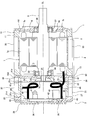
- FIG. 1 is a cross-sectional view showing an embodiment of a motor assembly 1.
- a motor assembly 1 shown in FIG. 1 is a mechanical device having an integrated structure in which an inverter 20 described later is built in and disposed on land.
- the motor assembly 1 includes a motor unit 2 and an inverter unit 3.
- the motor assembly 1 includes a drive shaft 5, a motor (rotating element) 8 including a rotor 6 for rotating the drive shaft 5 and a stator 7, and a motor casing 10 for housing the motor 8.
- the inverter 20 is disposed adjacent to the motor 8 and accommodates the inverter 20 for controlling the operation (rotational speed) of the motor 8 and the inverter 20, and is disposed in series in the motor casing 10 along the direction of the axis CL of the drive shaft 5 An inverter case 21 is provided.
- the drive shaft 5 extends through the motor casing 10 and the inverter case 21, and the motor casing 10 and the inverter case 21 are arranged concentrically with the drive shaft 5.
- the motor assembly 1 can have a compact structure.
- An external fan 25 concentrically disposed with the drive shaft 5 is fixed to an end of the drive shaft 5 (that is, the opposite load side of the drive shaft 5).
- the external fan 25 is adjacent to the inverter case 21 at a position outside the inverter case 21.
- a motor 8 which is a heat source is disposed inside the motor casing 10.
- a motor 8 includes a rotor 6 fixed to a drive shaft 5 and a stator (a stator (stator) that surrounds the rotor 6 and receives electric power from the outside (not shown) from a winding (coil) 7b. ) And 7).
- the stator 7 includes a stator core 7a and a plurality of windings 7b wound around the stator core 7a.
- the rotor 6 is rotated by a rotating magnetic field formed between the rotor 6 and the stator 7, and the drive shaft 5 to which the rotor 6 is fixed rotates with the rotor 6.
- the motor 8 is schematically depicted.
- the motor 8 is, for example, a permanent magnet type motor using a permanent magnet as a rotor.
- the motor 8 is not limited to a permanent magnet type motor, and may be various types of motors such as an induction motor and an SR motor.
- the motor casing 10 has a cylindrical motor frame 11 to which the stator 7 is fixed, and an end cover 12 in which one open end of the motor frame 11 is closed and a through hole 30 through which the drive shaft 5 passes is formed.
- the other open end of the motor frame 11 is closed, and a bracket 13 having a through hole 31 through which the drive shaft 5 passes is formed.
- the end cover 12 and the bracket 13 face each other with the motor 8 interposed therebetween.
- the drive shaft 5 is rotatably supported by a bearing 27 supported by the bearing support portion 32 of the end cover 12 and a bearing 28 supported by the bearing support portion 33 of the bracket 13.
- a plurality of fins 35 extending in the direction of the axis line CL of the drive shaft 5 are disposed on the outer surface of the motor frame 11.
- the fins 35 extend outward from the outer surface of the motor frame 11 and are arranged at equal intervals along the circumferential direction of the motor frame 11.
- the outer surface of the motor frame 11 is a surface opposite to the inner surface of the motor frame 11 to which the stator 7 is fixed.
- the inverter case 21 includes a cylindrical inverter frame 22 surrounding the inverter 20 and a cover member 23 closing the open end of the inverter frame 22.
- a plurality of fins 37 extending in the direction of the axis line CL of the drive shaft 5 are disposed on the outer surface of the inverter frame 22.
- the fins 37 extend outward from the outer surface of the inverter frame 22 and are arranged at equal intervals along the circumferential direction of the inverter frame 22.
- the outer surface of the inverter frame 22 is a surface opposite to the inner surface of the inverter frame 22 disposed around the inverter 20.
- the surface 21c on the cover member 23 side of the inverter frame 22 and the surface 21d on the inverter frame 22 side of the cover member 23 have a fitting structure, and the inverter frame 22 and the cover member 23 are mutually connected by fitting. It is done.
- a plurality of fins 36 are formed on the outer surface of the cover member 23. The fins 36 are adjacent to the outer fan 25 and extend from the outer surface of the cover member 23 toward the outer fan 25.
- the cover member 23 of the inverter case 21 is disposed concentrically with the drive shaft 5, and a through hole 40 through which the drive shaft 5 passes is formed at the center of the cover member 23.
- the drive shaft 5 extends to the outside of the inverter unit 3 through the through hole 40.
- the inverter 20 is disposed inside the inverter case 21.
- the inverter 20 includes an inverter element 41 including elements such as a switching element and a capacitor, and a substrate 42 on which the inverter element 41 is mounted.
- the substrate 42 is fixed to the inner surface of the cover member 23 via the spacer 43.
- the inner surface of the cover member 23 is a surface opposite to the outer surface of the cover member 23.
- the cover member 23 has a saucer shape on which the substrate 42 is placed. With such a structure, the cover member 23 can be filled with a resin for heat dissipation and surface protection of the substrate 42.
- the inverter case 21 plays a role as a heat sink of the inverter unit 3, and therefore, it has excellent heat conductivity such as a material (for example, aluminum (Al)) having relatively high heat dissipation performance. It is basically made of metal).
- the inverter frame 22 has a cylindrical shape in conformity with the outer shape of the motor frame 11.
- the inverter case 21 may have a structure matched to the shape of the motor casing 10.
- the inverter 20 is provided with a power line 45 for power supply and an electric line 46 for communication.
- the power line 45 and the electric line 46 are schematically drawn by thick lines.
- the power line 45 is a line that outputs power from the substrate 42 to the motor 8, and the electric line 46 includes a communication line connected to an apparatus such as a controller.
- the electrical wire 46 may be a plurality of wires including input wires and communication wires, or may be a single wire.
- the electric wire 46 is connected to a terminal box provided in the external space of the motor assembly 1 through a hole (not shown) formed in the inverter case 21. A hole through which the electrical wire 46 passes is closed by a sealing member in order to prevent contact of the air 20 with moisture and / or liquid such as rain to the inverter 20.
- the motor assembly 1 further includes a shaft cover 50 covering the periphery of the drive shaft 5.
- the shaft cover 50 is an isolation member that isolates the drive shaft 5 and the inverter 20.
- the shaft cover 50 has a cylindrical shape and is disposed concentrically with the drive shaft 5.
- the shape of the shaft cover 50 is not particularly limited.
- the shaft cover 50 extends in the direction of the axis line CL of the drive shaft 5.
- the inverter 20 i.e., the inverter element 41 and the substrate 42
- the power line 45, and the electric line 46 are disposed outside the shaft cover 50.
- the substrate 42 has an annular shape through which the drive shaft 5 and the shaft cover 50 pass, and the substrate 42 and the shaft cover 50 are arranged concentrically with the drive shaft 5.
- the power line 45 and the electric line 46 are disposed in the space between the inverter frame 22 and the shaft cover 50.
- the shaft cover 50 By providing the shaft cover 50, it is possible to prevent the winding of the power line 45 and the electric wire 46 to the drive shaft 5 and the contact of the inverter element 41 with the drive shaft 5. As a result, failure of inverter 20 can be reliably prevented.
- a fan cover 51 is attached to the cover member 23 so as to surround the external fan 25.
- the fan cover 51 is a member for guiding cooling air to the motor unit 2 side and the inverter unit 3 side.
- the fan cover 51 is disposed to cover the cover member 23.
- the fan cover 51 has an opening 51 a formed in the surface of the fan cover 51 facing the external fan 25.
- the external fan 25 can send air to the outer surface of the inverter case 21 and the outer surface of the motor casing 10 by its rotation, but can not send air to the space where the inverter 20 serving as the heat source is disposed.
- the inverter element 41 may be damaged or the life of the inverter element 41 (in particular, the capacitor) may be shortened.
- the motor assembly 1 can sufficiently cool the space in which the inverter 20 is disposed.
- the structure which can fully cool the space where inverter 20 is arranged, and can cool inverter 20 is explained, referring to drawings.
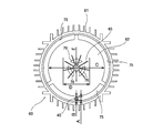
- FIG. 2 is a front view of the heat radiating member 60 when the heat radiating member 60 is viewed from the motor unit 2 side.
- the motor assembly 1 includes a heat dissipation member 60 disposed between the inverter case 21 and the motor casing 10.
- the heat dissipation member 60 is connected to the heat dissipation cover 61 connected to the inverter case 21 (more specifically, the inverter frame 22) and the motor casing 10 (more specifically, the bracket 13), and to the inner surface 61a of the heat dissipation cover 61 , And the heat dissipation plate 62 which divides the inverter space 66 in which the inverter 20 is arrange
- the inverter 20 is disposed in a sealed space formed by the inverter case 21, the heat dissipation cover 61, and the bracket 13 of the motor casing 10.
- the shaft cover 50 is connected to the cover member 23 and the heat dissipation plate 62.
- the heat dissipation plate 62 extends perpendicularly to the direction of the axis line CL of the drive shaft 5.
- the surface 61 b on the bracket 13 side of the heat dissipation cover 61 and the surface 10 d on the heat dissipation cover 61 side of the bracket 13 have a fitting structure, and the heat dissipation cover 61 and the bracket 13 are fitted They are connected to each other by their mates.
- the surface 61 c on the inverter frame 22 side of the heat radiation cover 61 is connected (fixed) to the surface 21 e on the heat radiation cover 61 side of the inverter frame 22.
- the surface (surface on the side of the inverter frame 22) 61c of the heat dissipation cover 61 and the surface (surface on the side of the heat dissipation cover 61) 21e of the inverter frame 22 have fitting structures, respectively.
- the inverter frame 22 may be connected to each other by fitting.
- the bracket 13 and the cover member 23 may be fastened by a fastener such as a through bolt in a state where the heat dissipation cover 61 and the inverter frame 22 are in close contact with each other.
- the heat dissipating cover 61 and the inverter frame 22 may be connected to each other by fixing means such as welding.
- the internal fan 65 is disposed between the heat dissipation plate 62 and the bracket 13 and is fixed to the drive shaft 5 (see FIG. 1).
- the internal fan 65 includes a boss portion 65a fixed to the drive shaft 5, and a plurality of wings 65b fixed to the boss portion 65a and arranged at equal intervals along the circumferential direction of the boss portion 65a (see FIG. 2).
- the internal fan 65 is a centrifugal fan, but the structure of the internal fan 65 is not particularly limited. If it is preferable to form a flow of air along the direction of the axis line CL of the drive shaft 5 by changing the elements including the inverter case 21 and the substrate 42, change the inclination of the wing 65b of the internal fan 65, etc. The shape of may be changed.
- the internal fan 65 may be an axial fan. In the present embodiment, nine wings 65b are provided, but the number of wings 65b may be changed as long as the motor efficiency is not affected. Since the internal fan 65 rotates with the rotation of the drive shaft 5, no special power supply for rotating the internal fan 65 is required.
- the number of internal fans 65 is not limited to this embodiment. Multiple internal fans 65 may be provided. Further, the internal fan 65 may be a combination of an axial fan and a centrifugal fan. In this case, the axial flow fan may be disposed on the heat radiation plate 62 side, and the centrifugal fan may be disposed on the bracket 13 side. Conversely, the centrifugal fan may be disposed on the heat dissipating plate 62 side, and the axial flow fan may be disposed on the bracket 13 side.
- the outer surface 61 d of the heat radiation cover 61 is formed with a plurality of fins 38 extending outward from the outer surface 61 d.
- the fins 38 are disposed on the entire outer surface 61 d of the heat dissipating cover 61. In one embodiment, these fins 38 may be disposed on a part of the outer surface 61 d of the heat dissipating cover 61.
- the heat dissipating cover 61 may include not only the fins 38 formed on the outer surface 61 d of the heat dissipating cover 61 but also a plurality of fins 39 formed on the inner surface 61 a of the heat dissipating cover 61.
- FIG. 3 is a view showing a plurality of fins 39 extending inward from the inner surface 61 a of the heat dissipation cover 61. As shown in FIG. 3, by providing the fins 38 and 39 on both the outer surface 61 d and the inner surface 61 a of the heat dissipating cover 61, the surface area of the heat dissipating cover 61 can be further increased.
- the heat dissipation plate 62 is provided with an air hole 70 which allows the flow of air due to the rotation of the internal fan 65 to be formed between the inverter space 66 and the fan space 67.
- the air holes 70 open on both sides of the heat dissipation plate 62, and the inverter space 66 and the fan space 67 communicate with each other through the air holes 70.
- the heat dissipating plate 62 is located outside the internal fan 65 and is located on the inner peripheral side located on the outer peripheral side portion (outside portion) 71 adjacent to the inner surface 61 a of the heat dissipating cover 61
- a site (inner site) 72 is provided.
- a through hole 72 a see FIG.
- the air hole 70 includes an outer peripheral hole (outer hole) 75 formed in the outer peripheral portion 71 and an inner peripheral hole (inner hole) 76 formed in the inner peripheral portion 72.
- the outer peripheral side holes 75 are a plurality of (three) openings, and the plurality of outer peripheral side holes 75 are arranged at equal intervals along the circumferential direction of the heat dissipation cover 61. In one embodiment, the number of outer peripheral holes 75 may be at least one.
- the inner circumferential side holes 76 are a plurality of (three) openings, and the plurality of inner circumferential side holes 76 are arranged at equal intervals along the circumferential direction of the heat dissipation cover 61 ing. In one embodiment, the number of inner holes 76 may be at least one. The three inner peripheral holes 76 are disposed at positions facing the internal fan 65.
- the inverter space 66 and the fan space 67 communicate with each other by the outer peripheral side hole 75 and the inner peripheral side hole 76, and the air can move in the inverter space 66 and the fan space 67.
- FIG. 4 is a view showing the flow of air as the internal fan 65 rotates.
- the illustration of the power line 45 and the electric line 46 is omitted.
- the air in the inverter space 66 flows into the fan space 67 through the inner circumferential hole 76. Thereafter, the air flowing into the fan space 67 collides with the surface 10 d of the bracket 13 and the air flow direction is changed.
- the air in the fan space 67 flows toward the heat dissipation cover 61 and collides with the inner surface 61 a of the heat dissipation cover 61.
- the flow direction of the air is further changed, and the air flows from the fan space 67 to the inverter space 66 through the outer peripheral hole 75.
- the air circulates through the inverter space 66 and the fan space 67 by the rotation of the internal fan 65, that is, a circulating flow of air is formed in the inverter space 66 and the fan space 67 and is warmed by the heat of the inverter 20.
- the air is stirred.
- the temperature of the air in the vicinity of the inverter 20 tends to rise by the heat of the inverter 20, and the temperature of the air in the vicinity of the motor 8, particularly in the vicinity of the winding 7b of the stator 7 tends to rise by the heat of the winding 7b.
- the temperature of air at a distance from the inverter 20 and the motor 8 tends to be low.
- the heat dissipation member 60 is disposed between the inverter case 21 and the motor casing 10 and is disposed at a position separated from the inverter 20 and the motor 8. Therefore, since the fan space 67 in which the internal fan 65 is disposed is separated from the inverter 20, the temperature of the fan space 67 is lower than the temperature of the inverter space 66.
- the heat dissipating member 60 constitutes a part of the casing of the motor assembly 1 and extends from the heat dissipating cover 61 toward the inside of the motor assembly 1 from the heat dissipating cover 61 in contact with the air in the space outside the motor assembly 1.
- a heat dissipation plate 62 is provided. When the internal fan 65 forms a circulating flow of air, the flowing air contacts the heat dissipation plate 62 and the heat of the inverter space 66 warmed by the inverter 20 is actively released to the outside of the heat dissipation cover 61.
- the heat dissipating plate 62 plays the role of a fin for increasing the surface area of the heat dissipating cover 61.
- the heated air flowing by the rotation of the internal fan 65 comes in contact with the heat dissipation plate 62, and the heat of this air is transmitted to the heat dissipation plate 62 and the heat dissipation cover 61 and released to the outside of the motor assembly 1 (FIG. 4). See dotted arrow). Furthermore, the air outside the motor assembly 1 that flows due to the rotation of the external fan 25 can contact the heat dissipation cover 61 and the fins 38 to take away the heat of the inverter 20.
- the material of the heat radiation plate 62 is not particularly limited, but a material having a high thermal conductivity (for example, copper or aluminum) is preferable.
- the heat dissipating cover 61 may be made of a material having a high thermal conductivity. Since the heat dissipating member 60 includes the heat dissipating cover 61 and the heat dissipating plate 62, the heat of the inverter space 66 warmed by the inverter 20 can be actively dissipated to the outside of the heat dissipating cover 61. As a result, the heat dissipation member 60 can cool the inverter 20.
- a power line 45 and an electric line 46 are disposed inside the motor assembly 1 (see FIG. 1).
- the power line 45 and the electric line 46 have a length long enough to allow an operator to remove the cover member 23 and check (visualize) the inverter 20. If the power line 45 and the electric line 46 contact the internal fan 65, the power line 45 and / or the electric line 46 may be disconnected or the inverter 20 may be broken. Therefore, in the present embodiment, the power line 45 is connected to the winding 7b of the stator 7 through the outer peripheral side hole 75 and the through hole 80 (see FIG. 1) of the bracket 13.
- the inner circumferential hole 76 Since the size of the inner circumferential hole 76 is smaller than the size (thickness) of the electric wire 46, the electric wire 46 passes through the inner circumferential hole 76 even if the length of the electric wire 46 is long. It is not exposed to the fan space 67. Therefore, the inner circumferential side hole 76 can prevent the electric wire 46 from contacting the internal fan 65.
- FIG. 5 is a view showing the relationship between the diameter of the power line 45 and the clearance of the outer peripheral hole 75 and the relationship between the diameter of the internal fan 65 and the diameter of the circle formed by the outer peripheral hole 75.
- the outer peripheral side hole 75 has a size through which the power line 45 can pass.
- the gap between the outer peripheral side holes 75, that is, the distance B is larger than the diameter A of the power line 45 (B> A).
- the diameter C of the circle formed by the outer peripheral side hole 75 is larger than the diameter D of the internal fan 65 (C> D). Therefore, the power line 45 passing through the outer peripheral side hole 75 does not contact the internal fan 65.
- the power line 45 Since the diameter A of the power line 45 is larger than the gap of the inner hole 76, ie, the distance E (A> E), the power line 45 does not pass through the inner hole 76. Although not shown, since the diameter of the electric wire 46 is also larger than the distance E, the electric wire 46 also does not pass through the inner circumferential hole 76.
- FIG. 6 is a view showing the passage hole 80 formed in the outer peripheral side portion 71.
- the power line 45 passes through the outer circumferential side hole 75, but as shown in FIG. 6, the outer circumferential side portion 71 of the heat dissipating plate 62 is a passing hole having a size through which the power line 45 can pass. It may have 80.
- one of the three outer peripheral holes 75 is divided, and the passage hole 80 is formed between the divided outer peripheral holes 75. In one embodiment, as long as the passage hole 80 is located outside the internal fan 65, the location is not particularly limited.
- the air holes 70 in the embodiment shown in FIG. 2 have a shape that does not inhibit the flow of air from the inverter space 66 to the fan space 67 and the flow of air from the fan space 67 to the inverter space 66.
- the shape of the air hole 70 is not limited to the embodiment shown in FIG. 2 as long as the circulating flow of air is not impeded.
- FIG. 7 is a view showing another embodiment of the air hole 70. As shown in FIG.
- the air hole 70 is provided with a slit 90 extending from the inner circumferential side portion 72 of the heat dissipation plate 62 toward the outer circumferential side portion 71.
- a slit 90 extending from the inner circumferential side portion 72 of the heat dissipation plate 62 toward the outer circumferential side portion 71.
- thirty slits 90 are provided, but the number of slits 90 is not limited to this embodiment. At least one slit 90 may be provided.
- the plurality of slits 90 extend radially, and a passage hole 80 is formed between two slits 90 adjacent to each other.
- the number, the arrangement, and the shape of the slits 90 are not particularly limited as long as the passage holes 80 can be formed in the outer peripheral side portion 71 of the heat dissipation plate 62.
- the internal fan 65 is an axial fan, but may be a centrifugal fan.
- the heat dissipating cover 61 may include not only the fins 38 formed on the outer surface 61 d of the heat dissipating cover 61 but also a plurality of fins 39 formed on the inner surface 61 a of the heat dissipating cover 61 (see FIG. 3).
- FIG. 8 is a view showing another embodiment of the air hole 70.
- one of the plurality of slits 90 has a length shorter than the other slits 90, and the passage hole 80 is disposed outside the slit 90 having this short length. ing.
- the number, the arrangement, and the shape of the slits 90 are not particularly limited as long as the passage holes 80 can be formed in the outer peripheral side portion 71 of the heat dissipation plate 62.
- the air holes 70 may be innumerable holes arranged regularly or randomly in the heat dissipation plate 62. Even in the embodiment shown in FIG. 8, a plurality of fins 39 may be formed on the inner surface 61 a of the heat dissipation cover 61 (see FIG. 3).
- FIG. 9 is a view showing another embodiment of the motor assembly 1.
- the configuration of the embodiment that is not particularly described is the same as the configuration of the embodiment described above, and thus the description thereof will not be repeated.
- the drive shaft 5 does not penetrate the heat dissipation plate 62 and the cover member 23, and an internal fan 65 is fixed to an end of the drive shaft 5.
- the motor assembly 1 since the motor assembly 1 includes the heat dissipation member 60, the inverter space 66 can be cooled by the flow of air due to the rotation of the internal fan 65 and the heat dissipation effect of the heat dissipation member 60.
- the present invention is applicable to a heat dissipating member and a motor assembly.
Abstract
The present invention relates to a heat dissipation member and a motor assembly. A heat dissipation member (60) comprises: a heat dissipation cover (61) which can be disposed between an inverter case (21) for housing an inverter (20) and a motor casing (10) for housing a motor (8) that comprises a rotor (6) for rotating a drive shaft (5) and a stator (7), and which can connect to the inverter case (21) and the motor casing (10); and a heat dissipation plate (62) which is connected to the inner surface of the heat dissipation cover (61) and can partition an inverter space (66) where the inverter (20) is disposed and a fan space (67) where an internal fan (65) fixed to the drive shaft (5) is disposed. The heat dissipation plate (62) includes an air hole (70) where an airflow caused by the internal fan (65) can be formed between the inverter space (66) and the fan space (67).
Description
本発明は、放熱部材および電動機組立体に関するものである。
The present invention relates to a heat dissipating member and a motor assembly.
インバータ部とモータ部とを備えた電動機組立体が知られている。このような電動機組立体において、インバータ部は、インバータと、インバータを収容するインバータケースとを備えている。モータ部は、駆動軸を回転させる回転子および固定子を備えるモータと、モータを収容するモータケーシングとを備えている。
A motor assembly comprising an inverter unit and a motor unit is known. In such a motor assembly, the inverter unit includes an inverter and an inverter case accommodating the inverter. The motor unit includes a motor having a rotor and a stator for rotating a drive shaft, and a motor casing for housing the motor.
インバータおよびモータは発熱源であるため、電動機組立体が運転されると、インバータの熱はインバータケースに伝達され、インバータケースは高温になる。同様に、モータの熱はモータケーシングに伝達され、モータケーシングは高温になる。結果として、電動機組立体は、その全体として非常に高温になる。したがって、電動機組立体は、駆動軸に固定され、かつインバータケースおよびモータケーシングの外部に配置されたファンを備えている。ファンは、駆動軸の回転とともに回転し、インバータケースの外面およびモータケーシングの外面を冷却する。インバータは冷却されたインバータケースを介して間接的に冷却され、モータは冷却されたモータケーシングを介して間接的に冷却される。
Since the inverter and the motor are heat sources, when the motor assembly is operated, the heat of the inverter is transferred to the inverter case, and the inverter case becomes hot. Similarly, the heat of the motor is transferred to the motor casing and the motor casing becomes hot. As a result, the motor assembly as a whole becomes very hot. Thus, the motor assembly comprises a fan fixed to the drive shaft and located outside the inverter case and the motor casing. The fan rotates with the rotation of the drive shaft to cool the outer surface of the inverter case and the outer surface of the motor casing. The inverter is indirectly cooled via the cooled inverter case, and the motor is indirectly cooled via the cooled motor casing.
しかしながら、ファンは、その回転によってインバータケースの外面およびモータケーシングの外面に空気を送ることはできるが、発熱源であるインバータが配置された空間、すなわち、インバータケースの内部空間に空気を送ることはできない。したがって、インバータケースの内部空間は十分に冷却されない。結果として、この内部空間は非常に高温になる場合がある。
However, although the fan can send air to the outer surface of the inverter case and the outer surface of the motor casing by its rotation, it can not send air to the space in which the inverter as the heat source is disposed, ie, the inner space of the inverter case. Can not. Therefore, the internal space of the inverter case is not sufficiently cooled. As a result, this interior space can be very hot.
インバータの構成要素は、インバータケースの内部空間の温度に依存して多大な影響を受けるため、インバータケースの内部空間が高温であると、インバータの構成要素が破損したり、インバータの構成要素の寿命が短くなることがある。したがって、インバータケースの内部空間の温度を低くすることは重要である。
Since the components of the inverter are greatly influenced depending on the temperature of the internal space of the inverter case, if the internal space of the inverter case is high temperature, the components of the inverter may be damaged or the lifetime of the components of the inverter may be May be shortened. Therefore, it is important to lower the temperature of the internal space of the inverter case.
そこで、本発明は、インバータが配置された空間を冷却することによって、インバータを冷却することができる放熱部材および該放熱部材を備えた電動機組立体を提供することを目的とする。
Then, this invention aims at providing the motor assembly provided with the thermal radiation member which can cool an inverter by cooling the space in which the inverter was arrange | positioned, and this thermal radiation member.
一態様は、インバータを収容するインバータケースと、駆動軸を回転させる回転子および固定子を備えるモータを収容するモータケーシングとの間に配置可能であり、かつ該インバータケースおよび該モータケーシングに接続可能な放熱カバーと、前記放熱カバーの内面に接続され、前記インバータが配置されたインバータ空間と前記駆動軸に固定された内部ファンが配置されたファン空間とを区画可能な放熱プレートとを備え、前記放熱プレートは、前記内部ファンによる空気の流れが前記インバータ空間と前記ファン空間との間に形成可能な空気孔を備えていることを特徴とする放熱部材である。
One aspect can be disposed between an inverter case housing an inverter and a motor casing containing a motor having a rotor for rotating a drive shaft and a stator, and can be connected to the inverter case and the motor casing A heat dissipating cover, and a heat dissipating plate capable of dividing an inverter space connected to the inner surface of the heat dissipating cover and in which the inverter is disposed and a fan space in which the internal fan fixed to the drive shaft is disposed; The heat dissipating plate is a heat dissipating member characterized by including an air hole which can be formed between the inverter space and the fan space by the flow of air from the internal fan.
好ましい態様は、前記放熱プレートは、前記内部ファンの外側に位置する外周側部位と、前記外周側部位の内側に位置する内周側部位とを備えており、前記空気孔は、前記外周側部位に形成された外周側孔部と、前記内周側部位に形成された内周側孔部とを備えていることを特徴とする。
好ましい態様は、前記外周側孔部は、前記インバータと前記モータとを接続する動力線が通過可能な大きさを有していることを特徴とする。
好ましい態様は、前記外周側部位には、前記インバータと前記モータとを接続する動力線が通過可能な大きさを有する通過孔が形成されていることを特徴とする。 In a preferable aspect, the heat dissipation plate includes an outer peripheral side portion positioned outside the internal fan and an inner peripheral side portion positioned inside the outer peripheral side portion, and the air hole is formed by the outer peripheral side portion An outer peripheral side hole formed in the above and an inner peripheral side hole formed in the inner peripheral side portion are characterized.
In a preferred aspect, the outer circumferential side hole has a size through which a power line connecting the inverter and the motor can pass.
A preferable aspect is characterized in that a passage hole having a size through which a power line connecting the inverter and the motor can pass is formed at the outer peripheral side portion.
好ましい態様は、前記放熱プレートは、前記内部ファンの外側に位置する外周側部位と、前記外周側部位の内側に位置する内周側部位とを備えており、前記空気孔は、前記内周側部位から前記外周側部位に向かって延びるスリットを備えていることを特徴とする。
好ましい態様は、前記外周側部位には、前記インバータと前記モータとを接続する動力線が通過可能な大きさを有する通過孔が形成されていることを特徴とする。 In a preferred aspect, the heat dissipation plate includes an outer peripheral side located outside the internal fan, and an inner peripheral side located inside the outer peripheral side, and the air hole is formed on the inner peripheral side. A slit is provided extending from a portion toward the outer peripheral portion.
A preferable aspect is characterized in that a passage hole having a size through which a power line connecting the inverter and the motor can pass is formed at the outer peripheral side portion.
他の態様は、駆動軸と、前記駆動軸を回転させる回転子および固定子を備えるモータと、前記モータを収容するモータケーシングと、前記モータに隣接して配置されたインバータと、前記インバータと前記モータとを接続する動力線と、前記インバータを収容し、前記駆動軸の軸線方向に沿って前記モータケーシングに直列的に配置されたインバータケースと、前記駆動軸に固定された内部ファンと、前記インバータケースと前記モータケーシングとの間に配置された放熱部材とを備え、前記放熱部材は、前記インバータケースおよび前記モータケーシングに接続された放熱カバーと、前記放熱カバーの内面に接続され、前記インバータが配置されたインバータ空間と前記内部ファンが配置されたファン空間とを区画する放熱プレートとを備えており、前記放熱プレートは、前記内部ファンによる空気の流れが前記インバータ空間と前記ファン空間との間に形成可能な空気孔を備えていることを特徴とする電動機組立体である。
Another aspect is a motor including a drive shaft, a rotor and a stator for rotating the drive shaft, a motor casing for accommodating the motor, an inverter disposed adjacent to the motor, the inverter, and A power line connecting the motor, an inverter case which accommodates the inverter and is arranged in series in the motor casing along an axial direction of the drive shaft, an internal fan fixed to the drive shaft, and A heat dissipation member disposed between the inverter case and the motor casing, the heat dissipation member being connected to the heat dissipation cover connected to the inverter case and the motor casing, and the inner surface of the heat dissipation cover, the inverter And a heat dissipation plate for partitioning the inverter space in which the internal fan is disposed and the fan space in which the internal fan is disposed. Eteori, the heat radiating plate, it is an electric motor assembly characterized by the flow of air by the internal fan with a formable air holes between the inverter space and the fan space.
好ましい態様は、前記放熱プレートは、前記内部ファンの外側に位置する外周側部位と、前記外周側部位の内側に位置する内周側部位とを備えており、前記空気孔は、前記外周側部位に形成された外周側孔部と、前記内周側部位に形成された内周側孔部とを備えていることを特徴とする。
好ましい態様は、前記外周側孔部は、前記動力線が通過可能な大きさを有していることを特徴とする。
好ましい態様は、前記外周側部位には、前記動力線が通過可能な大きさを有する通過孔が形成されていることを特徴とする。 In a preferable aspect, the heat dissipation plate includes an outer peripheral side portion positioned outside the internal fan and an inner peripheral side portion positioned inside the outer peripheral side portion, and the air hole is formed by the outer peripheral side portion An outer peripheral side hole formed in the above and an inner peripheral side hole formed in the inner peripheral side portion are characterized.
In a preferred aspect, the outer circumferential side hole has a size through which the power line can pass.
In a preferred aspect, the outer circumferential side portion is formed with a passage hole having a size through which the power line can pass.
好ましい態様は、前記放熱プレートは、前記内部ファンの外側に位置する外周側部位と、前記外周側部位の内側に位置する内周側部位とを備えており、前記空気孔は、前記内周側部位から前記外周側部位に向かって延びるスリットを備えていることを特徴とする。
好ましい態様は、前記外周側部位には、前記動力線が通過可能な大きさを有する通過孔が形成されていることを特徴とする。 In a preferred aspect, the heat dissipation plate includes an outer peripheral side located outside the internal fan, and an inner peripheral side located inside the outer peripheral side, and the air hole is formed on the inner peripheral side. A slit is provided extending from a portion toward the outer peripheral portion.
In a preferred aspect, the outer circumferential side portion is formed with a passage hole having a size through which the power line can pass.
放熱部材は、放熱カバーと、放熱プレートとを備えているため、インバータによって温められたインバータ空間の熱を放熱カバーの外部に積極的に放出することができる。結果として、放熱部材はインバータを冷却することができる。
The heat dissipating member includes the heat dissipating cover and the heat dissipating plate, so that the heat of the inverter space warmed by the inverter can be actively released to the outside of the heat dissipating cover. As a result, the heat dissipation member can cool the inverter.
以下、本発明の実施形態について図面を参照して説明する。なお、以下で説明する図面において、同一又は相当する構成要素には、同一の符号を付して重複した説明を省略する。以下で説明する複数の実施形態において、特に説明しない一実施形態の構成は、他の実施形態と同じであるので、その重複する説明を省略する。
Hereinafter, embodiments of the present invention will be described with reference to the drawings. In the drawings to be described below, the same or corresponding components are denoted by the same reference numerals and redundant description will be omitted. In the embodiments to be described below, the configuration of one embodiment that is not particularly described is the same as the other embodiments, and thus the description thereof will not be repeated.
図1は電動機組立体1の一実施形態を示す断面図である。図1に示す電動機組立体1は、後述するインバータ20が内蔵された一体型構造を有し、かつ陸上に配置される機械装置である。図1に示すように、電動機組立体1は、モータ部2と、インバータ部3とを備えている。電動機組立体1は、駆動軸5と、駆動軸5を回転させる回転子(ロータ)6および固定子(ステータ)7を備えるモータ(回転要素)8と、モータ8を収容するモータケーシング10と、モータ8に隣接して配置され、モータ8の動作(回転速度)を制御するインバータ20と、インバータ20を収容し、駆動軸5の軸線CL方向に沿ってモータケーシング10に直列的に配置されたインバータケース21とを備えている。
FIG. 1 is a cross-sectional view showing an embodiment of a motor assembly 1. A motor assembly 1 shown in FIG. 1 is a mechanical device having an integrated structure in which an inverter 20 described later is built in and disposed on land. As shown in FIG. 1, the motor assembly 1 includes a motor unit 2 and an inverter unit 3. The motor assembly 1 includes a drive shaft 5, a motor (rotating element) 8 including a rotor 6 for rotating the drive shaft 5 and a stator 7, and a motor casing 10 for housing the motor 8. The inverter 20 is disposed adjacent to the motor 8 and accommodates the inverter 20 for controlling the operation (rotational speed) of the motor 8 and the inverter 20, and is disposed in series in the motor casing 10 along the direction of the axis CL of the drive shaft 5 An inverter case 21 is provided.
駆動軸5は、モータケーシング10およびインバータケース21を貫通して延びており、モータケーシング10およびインバータケース21は駆動軸5と同心状に配置されている。本実施形態では、モータケーシング10およびインバータケース21は、駆動軸5の軸線CL方向に直列的に配置されているため、電動機組立体1はコンパクトな構造を有することができる。駆動軸5の端部(すなわち、駆動軸5の反負荷側)には、駆動軸5と同心状に配置された外部ファン25が固定されている。外部ファン25は、インバータケース21の外側の位置において、インバータケース21に隣接している。
The drive shaft 5 extends through the motor casing 10 and the inverter case 21, and the motor casing 10 and the inverter case 21 are arranged concentrically with the drive shaft 5. In the present embodiment, since the motor casing 10 and the inverter case 21 are arranged in series in the direction of the axis line CL of the drive shaft 5, the motor assembly 1 can have a compact structure. An external fan 25 concentrically disposed with the drive shaft 5 is fixed to an end of the drive shaft 5 (that is, the opposite load side of the drive shaft 5). The external fan 25 is adjacent to the inverter case 21 at a position outside the inverter case 21.
モータケーシング10の内部には、発熱源であるモータ8が配置されている。モータ8は、駆動軸5に固定された回転子6と、回転子6を囲んで、外部(図示しない)からの電力を巻線(コイル)7bが受けて回転磁界を形成する固定子(ステータ)7とを備えている。固定子7は、ステータコア7aと、ステータコア7aに巻かれた複数の巻線7bとを備えている。回転子6は、回転子6と固定子7との間に形成される回転磁界によって回転し、回転子6が固定された駆動軸5は回転子6とともに回転する。
Inside the motor casing 10, a motor 8 which is a heat source is disposed. A motor 8 includes a rotor 6 fixed to a drive shaft 5 and a stator (a stator (stator) that surrounds the rotor 6 and receives electric power from the outside (not shown) from a winding (coil) 7b. ) And 7). The stator 7 includes a stator core 7a and a plurality of windings 7b wound around the stator core 7a. The rotor 6 is rotated by a rotating magnetic field formed between the rotor 6 and the stator 7, and the drive shaft 5 to which the rotor 6 is fixed rotates with the rotor 6.
図1において、モータ8は模式的に描かれている。モータ8は、例えば、ロータに永久磁石を用いた永久磁石型モータである。しかしながら、モータ8は、永久磁石型モータに限定されず、誘導モータやSRモータなど、様々な種類のモータであってもよい。
In FIG. 1, the motor 8 is schematically depicted. The motor 8 is, for example, a permanent magnet type motor using a permanent magnet as a rotor. However, the motor 8 is not limited to a permanent magnet type motor, and may be various types of motors such as an induction motor and an SR motor.
モータケーシング10は、固定子7が固定された筒状のモータフレーム11と、モータフレーム11の一方の開口端を閉じ、かつ駆動軸5が貫通する貫通孔30が形成されたエンドカバー12と、モータフレーム11の他方の開口端を閉じ、かつ駆動軸5が貫通する貫通孔31が形成されたブラケット13とを備えている。エンドカバー12およびブラケット13は、モータ8を挟んで互いに対向している。駆動軸5は、エンドカバー12の軸受支持部32に支持された軸受27およびブラケット13の軸受支持部33に支持された軸受28によって回転自在に支持されている。
The motor casing 10 has a cylindrical motor frame 11 to which the stator 7 is fixed, and an end cover 12 in which one open end of the motor frame 11 is closed and a through hole 30 through which the drive shaft 5 passes is formed. The other open end of the motor frame 11 is closed, and a bracket 13 having a through hole 31 through which the drive shaft 5 passes is formed. The end cover 12 and the bracket 13 face each other with the motor 8 interposed therebetween. The drive shaft 5 is rotatably supported by a bearing 27 supported by the bearing support portion 32 of the end cover 12 and a bearing 28 supported by the bearing support portion 33 of the bracket 13.
モータフレーム11の外面には、駆動軸5の軸線CL方向に延びる複数のフィン35が配置されている。これらフィン35は、モータフレーム11の外面から外側に向かって延びており、モータフレーム11の周方向に沿って等間隔に配置されている。モータフレーム11の外面は固定子7が固定されたモータフレーム11の内面とは反対側の面である。
A plurality of fins 35 extending in the direction of the axis line CL of the drive shaft 5 are disposed on the outer surface of the motor frame 11. The fins 35 extend outward from the outer surface of the motor frame 11 and are arranged at equal intervals along the circumferential direction of the motor frame 11. The outer surface of the motor frame 11 is a surface opposite to the inner surface of the motor frame 11 to which the stator 7 is fixed.
インバータケース21は、インバータ20を取り囲む筒状のインバータフレーム22と、インバータフレーム22の開口端を閉じるカバー部材23とを備えている。インバータフレーム22の外面には、駆動軸5の軸線CL方向に延びる複数のフィン37が配置されている。これらフィン37は、インバータフレーム22の外面から外側に向かって延びており、インバータフレーム22の周方向に沿って等間隔に配置されている。インバータフレーム22の外面はインバータ20の周囲に配置されたインバータフレーム22の内面とは反対側の面である。
The inverter case 21 includes a cylindrical inverter frame 22 surrounding the inverter 20 and a cover member 23 closing the open end of the inverter frame 22. A plurality of fins 37 extending in the direction of the axis line CL of the drive shaft 5 are disposed on the outer surface of the inverter frame 22. The fins 37 extend outward from the outer surface of the inverter frame 22 and are arranged at equal intervals along the circumferential direction of the inverter frame 22. The outer surface of the inverter frame 22 is a surface opposite to the inner surface of the inverter frame 22 disposed around the inverter 20.
インバータフレーム22のカバー部材23側の面21cおよびカバー部材23のインバータフレーム22側の面21dは、それぞれ嵌め合い構造を有しており、これらインバータフレーム22およびカバー部材23は、嵌め合いによって互いに接続されている。カバー部材23の外面には、複数のフィン36が形成されている。これらフィン36は、外部ファン25に隣接しており、カバー部材23の外面から外部ファン25に向かって延びている。
The surface 21c on the cover member 23 side of the inverter frame 22 and the surface 21d on the inverter frame 22 side of the cover member 23 have a fitting structure, and the inverter frame 22 and the cover member 23 are mutually connected by fitting. It is done. A plurality of fins 36 are formed on the outer surface of the cover member 23. The fins 36 are adjacent to the outer fan 25 and extend from the outer surface of the cover member 23 toward the outer fan 25.
インバータケース21のカバー部材23は駆動軸5と同心状に配置されており、カバー部材23の中央には、駆動軸5が貫通する貫通孔40が形成されている。駆動軸5は、この貫通孔40を通ってインバータ部3の外部まで延びている。
The cover member 23 of the inverter case 21 is disposed concentrically with the drive shaft 5, and a through hole 40 through which the drive shaft 5 passes is formed at the center of the cover member 23. The drive shaft 5 extends to the outside of the inverter unit 3 through the through hole 40.
インバータケース21の内部には、インバータ20が配置されている。インバータ20は、スイッチング素子やコンデンサなどの要素を含むインバータ要素41と、このインバータ要素41が実装された基板42とを備えている。基板42はスペーサ43を介してカバー部材23の内面に固定されている。カバー部材23の内面はカバー部材23の外面とは反対側の面である。カバー部材23は基板42が載置される受け皿形状を有している。このような構造により、カバー部材23には、基板42の放熱用および表面保護用の樹脂を充填することができる。
An inverter 20 is disposed inside the inverter case 21. The inverter 20 includes an inverter element 41 including elements such as a switching element and a capacitor, and a substrate 42 on which the inverter element 41 is mounted. The substrate 42 is fixed to the inner surface of the cover member 23 via the spacer 43. The inner surface of the cover member 23 is a surface opposite to the outer surface of the cover member 23. The cover member 23 has a saucer shape on which the substrate 42 is placed. With such a structure, the cover member 23 can be filled with a resin for heat dissipation and surface protection of the substrate 42.
インバータケース21(特に、カバー部材23およびフィン36)は、インバータ部3のヒートシンクとしての役割を果たすため、比較的高い放熱性能を有する材料(例えば、アルミニウム(Al)などの熱伝導性に優れた金属)から、基本的に構成されている。本実施形態では、インバータフレーム22はモータフレーム11の外形形状に合わせて円筒形状を有している。一実施形態では、モータケーシング10がフィンや端子箱などの部材によって特殊な外形形状を有している場合、インバータケース21は、このモータケーシング10の形状に合わせた構造を有してもよい。
The inverter case 21 (in particular, the cover member 23 and the fins 36) plays a role as a heat sink of the inverter unit 3, and therefore, it has excellent heat conductivity such as a material (for example, aluminum (Al)) having relatively high heat dissipation performance. It is basically made of metal). In the present embodiment, the inverter frame 22 has a cylindrical shape in conformity with the outer shape of the motor frame 11. In one embodiment, when the motor casing 10 has a special external shape by a member such as a fin or a terminal box, the inverter case 21 may have a structure matched to the shape of the motor casing 10.
インバータ20には、給電のための動力線45および通信のための電気線46が設けられている。図1では、動力線45および電気線46は模式的に太線で描かれている。動力線45は電力を基板42からモータ8に出力する線であり、電気線46はコントローラなどの機器に接続された通信用の配線を含む。電気線46は、入力線および通信線を含む複数の線であってもよく、または単一の線であってもよい。電気線46は、インバータケース21に形成された図示しない孔を通じて、電動機組立体1の外部空間に設けられた端子箱に接続されている。空気中の湿気および/または雨などの液体のインバータ20への接触を防止するために、電気線46が通過する孔は封止部材によって閉じられている。
The inverter 20 is provided with a power line 45 for power supply and an electric line 46 for communication. In FIG. 1, the power line 45 and the electric line 46 are schematically drawn by thick lines. The power line 45 is a line that outputs power from the substrate 42 to the motor 8, and the electric line 46 includes a communication line connected to an apparatus such as a controller. The electrical wire 46 may be a plurality of wires including input wires and communication wires, or may be a single wire. The electric wire 46 is connected to a terminal box provided in the external space of the motor assembly 1 through a hole (not shown) formed in the inverter case 21. A hole through which the electrical wire 46 passes is closed by a sealing member in order to prevent contact of the air 20 with moisture and / or liquid such as rain to the inverter 20.
電動機組立体1は、駆動軸5の周囲を覆う軸カバー50をさらに備えている。この軸カバー50は、駆動軸5とインバータ20とを隔離する隔離部材である。軸カバー50は、円筒形状を有しており、駆動軸5と同心状に配置されている。軸カバー50の形状は特に限定されない。軸カバー50は、駆動軸5の軸線CL方向に延びている。インバータ20(すなわち、インバータ要素41および基板42)、動力線45、および電気線46は、軸カバー50の外側に配置されている。基板42は、駆動軸5および軸カバー50が貫通する環状形状を有しており、基板42および軸カバー50は駆動軸5と同心状に配置されている。動力線45および電気線46は、インバータフレーム22と軸カバー50との間の空間に配置されている。軸カバー50を設けることにより、動力線45および電気線46の駆動軸5への巻き込み、およびインバータ要素41の駆動軸5との接触を防止することができる。結果として、インバータ20の故障を確実に防止することができる。
The motor assembly 1 further includes a shaft cover 50 covering the periphery of the drive shaft 5. The shaft cover 50 is an isolation member that isolates the drive shaft 5 and the inverter 20. The shaft cover 50 has a cylindrical shape and is disposed concentrically with the drive shaft 5. The shape of the shaft cover 50 is not particularly limited. The shaft cover 50 extends in the direction of the axis line CL of the drive shaft 5. The inverter 20 (i.e., the inverter element 41 and the substrate 42), the power line 45, and the electric line 46 are disposed outside the shaft cover 50. The substrate 42 has an annular shape through which the drive shaft 5 and the shaft cover 50 pass, and the substrate 42 and the shaft cover 50 are arranged concentrically with the drive shaft 5. The power line 45 and the electric line 46 are disposed in the space between the inverter frame 22 and the shaft cover 50. By providing the shaft cover 50, it is possible to prevent the winding of the power line 45 and the electric wire 46 to the drive shaft 5 and the contact of the inverter element 41 with the drive shaft 5. As a result, failure of inverter 20 can be reliably prevented.
カバー部材23には、外部ファン25を囲むようにファンカバー51が取り付けられている。ファンカバー51は、冷却用の空気をモータ部2側およびインバータ部3側に案内するための部材である。ファンカバー51は、カバー部材23を覆うように配置されている。ファンカバー51は、外部ファン25に対向するファンカバー51の面に形成された開口51aを有している。
A fan cover 51 is attached to the cover member 23 so as to surround the external fan 25. The fan cover 51 is a member for guiding cooling air to the motor unit 2 side and the inverter unit 3 side. The fan cover 51 is disposed to cover the cover member 23. The fan cover 51 has an opening 51 a formed in the surface of the fan cover 51 facing the external fan 25.
外部ファン25が駆動軸5とともに回転すると、空気は開口51aを通じてインバータケース21およびモータケーシング10に送られる。この空気は、インバータケース21、モータケーシング10、フィン35,36,37、および後述する放熱部材60の放熱カバー61の外面に形成されたフィン38に接触してインバータ20およびモータ8の熱を奪う。
When the external fan 25 rotates with the drive shaft 5, air is sent to the inverter case 21 and the motor casing 10 through the opening 51a. The air contacts the inverter case 21, the motor casing 10, the fins 35, 36, 37 and the fins 38 formed on the outer surface of the heat dissipation cover 61 of the heat dissipation member 60 described later to remove heat from the inverter 20 and the motor 8. .
外部ファン25は、その回転によってインバータケース21の外面およびモータケーシング10の外面に空気を送ることはできるが、発熱源であるインバータ20が配置された空間に空気を送ることはできない。上述したように、インバータ20の構成要素であるインバータ要素41の周囲が高温であると、インバータ要素41が破損したり、インバータ要素41(特に、コンデンサ)の寿命が短くなることがある。本実施形態では、電動機組立体1は、インバータ20が配置された空間を十分に冷却することができる。以下、インバータ20が配置された空間を十分に冷却して、インバータ20を冷却することができる構成について図面を参照しつつ説明する。
The external fan 25 can send air to the outer surface of the inverter case 21 and the outer surface of the motor casing 10 by its rotation, but can not send air to the space where the inverter 20 serving as the heat source is disposed. As described above, if the temperature around the inverter element 41 which is a component of the inverter 20 is high, the inverter element 41 may be damaged or the life of the inverter element 41 (in particular, the capacitor) may be shortened. In the present embodiment, the motor assembly 1 can sufficiently cool the space in which the inverter 20 is disposed. Hereinafter, the structure which can fully cool the space where inverter 20 is arranged, and can cool inverter 20 is explained, referring to drawings.
図2は、放熱部材60をモータ部2側から見たときの放熱部材60の正面図である。電動機組立体1は、インバータケース21とモータケーシング10との間に配置された放熱部材60を備えている。放熱部材60は、インバータケース21(より具体的には、インバータフレーム22)およびモータケーシング10(より具体的には、ブラケット13)に接続された放熱カバー61と、放熱カバー61の内面61aに接続され、インバータ20が配置されたインバータ空間66と、内部ファン65が配置されたファン空間67とを区画する放熱プレート62とを備えている。インバータ20は、インバータケース21、放熱カバー61、およびモータケーシング10のブラケット13によって形成された密閉空間に配置されている。軸カバー50はカバー部材23および放熱プレート62に接続されている。放熱プレート62は、駆動軸5の軸線CL方向に対して垂直に延びている。
FIG. 2 is a front view of the heat radiating member 60 when the heat radiating member 60 is viewed from the motor unit 2 side. The motor assembly 1 includes a heat dissipation member 60 disposed between the inverter case 21 and the motor casing 10. The heat dissipation member 60 is connected to the heat dissipation cover 61 connected to the inverter case 21 (more specifically, the inverter frame 22) and the motor casing 10 (more specifically, the bracket 13), and to the inner surface 61a of the heat dissipation cover 61 , And the heat dissipation plate 62 which divides the inverter space 66 in which the inverter 20 is arrange | positioned, and the fan space 67 in which the internal fan 65 is arrange | positioned. The inverter 20 is disposed in a sealed space formed by the inverter case 21, the heat dissipation cover 61, and the bracket 13 of the motor casing 10. The shaft cover 50 is connected to the cover member 23 and the heat dissipation plate 62. The heat dissipation plate 62 extends perpendicularly to the direction of the axis line CL of the drive shaft 5.
図1に示すように、放熱カバー61のブラケット13側の面61bおよびブラケット13の放熱カバー61側の面10dは、それぞれ嵌め合い構造を有しており、これら放熱カバー61およびブラケット13は、嵌め合いによって互いに接続されている。放熱カバー61のインバータフレーム22側の面61cはインバータフレーム22の放熱カバー61側の面21eに接続(固定)されている。
As shown in FIG. 1, the surface 61 b on the bracket 13 side of the heat dissipation cover 61 and the surface 10 d on the heat dissipation cover 61 side of the bracket 13 have a fitting structure, and the heat dissipation cover 61 and the bracket 13 are fitted They are connected to each other by their mates. The surface 61 c on the inverter frame 22 side of the heat radiation cover 61 is connected (fixed) to the surface 21 e on the heat radiation cover 61 side of the inverter frame 22.
一実施形態では、放熱カバー61の面(インバータフレーム22側の面)61cおよびインバータフレーム22の面(放熱カバー61側の面)21eは、それぞれ嵌め合い構造を有しており、これら放熱カバー61およびインバータフレーム22は、嵌め合いによって互いに接続されていてもよい。他の実施形態では、放熱カバー61およびインバータフレーム22を密着させた状態で、通しボルトなどの締結具によってブラケット13およびカバー部材23を締結してもよい。さらに他の実施形態では、放熱カバー61およびインバータフレーム22は溶接などの固定手段によって互いに接続されてもよい。
In one embodiment, the surface (surface on the side of the inverter frame 22) 61c of the heat dissipation cover 61 and the surface (surface on the side of the heat dissipation cover 61) 21e of the inverter frame 22 have fitting structures, respectively. And the inverter frame 22 may be connected to each other by fitting. In another embodiment, the bracket 13 and the cover member 23 may be fastened by a fastener such as a through bolt in a state where the heat dissipation cover 61 and the inverter frame 22 are in close contact with each other. In still another embodiment, the heat dissipating cover 61 and the inverter frame 22 may be connected to each other by fixing means such as welding.
内部ファン65は、放熱プレート62とブラケット13との間に配置されており、駆動軸5に固定されている(図1参照)。内部ファン65は、駆動軸5に固定されたボス部65aと、ボス部65aに固定され、ボス部65aの周方向に沿って等間隔に配置された複数の翼65bとを備えている(図2参照)。
The internal fan 65 is disposed between the heat dissipation plate 62 and the bracket 13 and is fixed to the drive shaft 5 (see FIG. 1). The internal fan 65 includes a boss portion 65a fixed to the drive shaft 5, and a plurality of wings 65b fixed to the boss portion 65a and arranged at equal intervals along the circumferential direction of the boss portion 65a (see FIG. 2).
本実施形態では、内部ファン65は、遠心ファンであるが、内部ファン65の構造は特に限定されない。インバータケース21および基板42を含む要素の変更により、駆動軸5の軸線CL方向に沿って空気の流れを形成することが好ましい場合、内部ファン65の翼65bの傾きを変更するなど、内部ファン65の形状を変更してもよい。一実施形態では、内部ファン65は、軸流ファンであってもよい。本実施形態では、9枚の翼65bが設けられているが、翼65bの枚数は、モータ効率に影響のない範囲であれば、変更されてもよい。内部ファン65は、駆動軸5の回転とともに回転するため、内部ファン65を回転させるための特別な電源は不要である。
In the present embodiment, the internal fan 65 is a centrifugal fan, but the structure of the internal fan 65 is not particularly limited. If it is preferable to form a flow of air along the direction of the axis line CL of the drive shaft 5 by changing the elements including the inverter case 21 and the substrate 42, change the inclination of the wing 65b of the internal fan 65, etc. The shape of may be changed. In one embodiment, the internal fan 65 may be an axial fan. In the present embodiment, nine wings 65b are provided, but the number of wings 65b may be changed as long as the motor efficiency is not affected. Since the internal fan 65 rotates with the rotation of the drive shaft 5, no special power supply for rotating the internal fan 65 is required.
本実施形態では、単一の内部ファン65が設けられているが、内部ファン65の数は本実施形態には限定されない。複数の内部ファン65が設けられてもよい。また、内部ファン65は、軸流ファンと遠心ファンとの組み合わせであってもよい。この場合、放熱プレート62側に軸流ファンを配置し、ブラケット13側に遠心ファンを配置してもよい。逆に、放熱プレート62側に遠心ファンを配置し、ブラケット13側に軸流ファンを配置してもよい。
Although a single internal fan 65 is provided in this embodiment, the number of internal fans 65 is not limited to this embodiment. Multiple internal fans 65 may be provided. Further, the internal fan 65 may be a combination of an axial fan and a centrifugal fan. In this case, the axial flow fan may be disposed on the heat radiation plate 62 side, and the centrifugal fan may be disposed on the bracket 13 side. Conversely, the centrifugal fan may be disposed on the heat dissipating plate 62 side, and the axial flow fan may be disposed on the bracket 13 side.
図2に示すように、放熱カバー61の外面61dには、外面61dから外側に向かって延びる複数のフィン38が形成されている。本実施形態では、これらフィン38は放熱カバー61の外面61dの全体に配置されている。一実施形態では、これらフィン38は放熱カバー61の外面61dの一部に配置されてもよい。他の実施形態では、放熱カバー61は、放熱カバー61の外面61dに形成されたフィン38のみならず、放熱カバー61の内面61aに形成された複数のフィン39を備えてもよい。
As shown in FIG. 2, the outer surface 61 d of the heat radiation cover 61 is formed with a plurality of fins 38 extending outward from the outer surface 61 d. In the present embodiment, the fins 38 are disposed on the entire outer surface 61 d of the heat dissipating cover 61. In one embodiment, these fins 38 may be disposed on a part of the outer surface 61 d of the heat dissipating cover 61. In another embodiment, the heat dissipating cover 61 may include not only the fins 38 formed on the outer surface 61 d of the heat dissipating cover 61 but also a plurality of fins 39 formed on the inner surface 61 a of the heat dissipating cover 61.
図3は放熱カバー61の内面61aから内側に向かって延びる複数のフィン39を示す図である。図3に示すように、放熱カバー61の外面61dおよび内面61aの両方にフィン38およびフィン39をそれぞれ設けることにより、放熱カバー61の表面積をより大きくすることができる。
FIG. 3 is a view showing a plurality of fins 39 extending inward from the inner surface 61 a of the heat dissipation cover 61. As shown in FIG. 3, by providing the fins 38 and 39 on both the outer surface 61 d and the inner surface 61 a of the heat dissipating cover 61, the surface area of the heat dissipating cover 61 can be further increased.
図2に示すように、放熱プレート62は、内部ファン65の回転による空気の流れがインバータ空間66およびファン空間67との間に形成可能な空気孔70を備えている。空気孔70は、放熱プレート62の両面で開口しており、インバータ空間66およびファン空間67は、空気孔70を通じて連通している。本実施形態では、放熱プレート62は、内部ファン65の外側に位置し、放熱カバー61の内面61aに隣接する外周側部位(外側部位)71と、外周側部位71の内側に位置する内周側部位(内側部位)72とを備えている。内周側部位72には、駆動軸5が貫通する貫通孔72a(図1参照)が形成されており、放熱プレート62は駆動軸5と同心状に配置されている。空気孔70は、外周側部位71に形成された外周側孔部(外側孔部)75と、内周側部位72に形成された内周側孔部(内側孔部)76とを備えている。本実施形態では、外周側孔部75は複数の(3つの)開口であり、これら複数の外周側孔部75は、放熱カバー61の周方向に沿って等間隔に配置されている。一実施形態では、外周側孔部75の数は少なくとも1であってもよい。
As shown in FIG. 2, the heat dissipation plate 62 is provided with an air hole 70 which allows the flow of air due to the rotation of the internal fan 65 to be formed between the inverter space 66 and the fan space 67. The air holes 70 open on both sides of the heat dissipation plate 62, and the inverter space 66 and the fan space 67 communicate with each other through the air holes 70. In the present embodiment, the heat dissipating plate 62 is located outside the internal fan 65 and is located on the inner peripheral side located on the outer peripheral side portion (outside portion) 71 adjacent to the inner surface 61 a of the heat dissipating cover 61 A site (inner site) 72 is provided. A through hole 72 a (see FIG. 1) through which the drive shaft 5 passes is formed in the inner circumferential side portion 72, and the heat dissipation plate 62 is disposed concentrically with the drive shaft 5. The air hole 70 includes an outer peripheral hole (outer hole) 75 formed in the outer peripheral portion 71 and an inner peripheral hole (inner hole) 76 formed in the inner peripheral portion 72. . In the present embodiment, the outer peripheral side holes 75 are a plurality of (three) openings, and the plurality of outer peripheral side holes 75 are arranged at equal intervals along the circumferential direction of the heat dissipation cover 61. In one embodiment, the number of outer peripheral holes 75 may be at least one.
同様に、本実施形態では、内周側孔部76は複数の(3つの)開口であり、これら複数の内周側孔部76は、放熱カバー61の周方向に沿って等間隔に配置されている。一実施形態では、内周側孔部76の数は少なくとも1であってもよい。これら3つの内周側孔部76は内部ファン65に対向する位置に配置されている。
Similarly, in the present embodiment, the inner circumferential side holes 76 are a plurality of (three) openings, and the plurality of inner circumferential side holes 76 are arranged at equal intervals along the circumferential direction of the heat dissipation cover 61 ing. In one embodiment, the number of inner holes 76 may be at least one. The three inner peripheral holes 76 are disposed at positions facing the internal fan 65.
インバータ空間66およびファン空間67は、外周側孔部75および内周側孔部76によって互いに連通しており、これらインバータ空間66およびファン空間67において、空気の移動が可能である。
The inverter space 66 and the fan space 67 communicate with each other by the outer peripheral side hole 75 and the inner peripheral side hole 76, and the air can move in the inverter space 66 and the fan space 67.
図4は内部ファン65の回転による空気の流れを示す図である。図4において、動力線45および電気線46の図示は省略されている。図4に示すように、内部ファン65が回転すると、インバータ空間66の空気は内周側孔部76を通って、ファン空間67に流入する。その後、ファン空間67に流入した空気はブラケット13の面10dに衝突し、空気の流れ方向が転換される。ファン空間67内の空気は放熱カバー61に向かって流れ、放熱カバー61の内面61aに衝突する。空気の流れ方向はさらに転換され、空気は、外周側孔部75を通って、ファン空間67からインバータ空間66に流れる。このように、空気は内部ファン65の回転によってインバータ空間66およびファン空間67を循環し、すなわち、インバータ空間66およびファン空間67には、空気の循環流が形成され、インバータ20の熱によって温められた空気は攪拌される。
FIG. 4 is a view showing the flow of air as the internal fan 65 rotates. In FIG. 4, the illustration of the power line 45 and the electric line 46 is omitted. As shown in FIG. 4, when the internal fan 65 rotates, the air in the inverter space 66 flows into the fan space 67 through the inner circumferential hole 76. Thereafter, the air flowing into the fan space 67 collides with the surface 10 d of the bracket 13 and the air flow direction is changed. The air in the fan space 67 flows toward the heat dissipation cover 61 and collides with the inner surface 61 a of the heat dissipation cover 61. The flow direction of the air is further changed, and the air flows from the fan space 67 to the inverter space 66 through the outer peripheral hole 75. Thus, the air circulates through the inverter space 66 and the fan space 67 by the rotation of the internal fan 65, that is, a circulating flow of air is formed in the inverter space 66 and the fan space 67 and is warmed by the heat of the inverter 20. The air is stirred.
インバータ20付近の空気の温度はインバータ20の熱によって上昇する傾向にあり、モータ8付近、特に、固定子7の巻線7b付近の空気の温度は巻線7bの熱によって上昇する傾向にある。その一方で、インバータ20およびモータ8から離間した位置の空気の温度は低い傾向にある。放熱部材60は、インバータケース21とモータケーシング10との間に配置されており、インバータ20およびモータ8から離間した位置に配置されている。したがって、内部ファン65が配置されたファン空間67はインバータ20から離間しているため、ファン空間67の温度はインバータ空間66の温度よりも低い。内部ファン65の回転によって、インバータ空間66およびファン空間67に空気の循環流が形成されると、インバータ20の熱によって温められたインバータ空間66の空気は冷却され、これらインバータ空間66の空気の温度およびファン空間67の空気の温度は均一になる。結果として、インバータ20は冷却される。
The temperature of the air in the vicinity of the inverter 20 tends to rise by the heat of the inverter 20, and the temperature of the air in the vicinity of the motor 8, particularly in the vicinity of the winding 7b of the stator 7 tends to rise by the heat of the winding 7b. On the other hand, the temperature of air at a distance from the inverter 20 and the motor 8 tends to be low. The heat dissipation member 60 is disposed between the inverter case 21 and the motor casing 10 and is disposed at a position separated from the inverter 20 and the motor 8. Therefore, since the fan space 67 in which the internal fan 65 is disposed is separated from the inverter 20, the temperature of the fan space 67 is lower than the temperature of the inverter space 66. When the circulating flow of air is formed in the inverter space 66 and the fan space 67 by the rotation of the internal fan 65, the air in the inverter space 66 warmed by the heat of the inverter 20 is cooled, and the temperature of the air in these inverter spaces 66 And the temperature of the air in the fan space 67 becomes uniform. As a result, the inverter 20 is cooled.
放熱部材60は、電動機組立体1の筐体の一部を構成し、電動機組立体1の外部空間の空気と接触する放熱カバー61と、放熱カバー61から電動機組立体1の内部に向かって延びる放熱プレート62とを備えている。内部ファン65が空気の循環流を形成すると、流れる空気は放熱プレート62に接触し、インバータ20によって温められたインバータ空間66の熱は放熱カバー61の外部に積極的に放出される。放熱プレート62は、放熱カバー61の表面積を大きくするためのフィンの役割を果たしている。内部ファン65の回転によって流れる温められた空気は放熱プレート62に接触し、この空気の熱は、放熱プレート62および放熱カバー61を伝達して、電動機組立体1の外部に放出される(図4の点線矢印参照)。さらに、外部ファン25の回転によって流れる電動機組立体1の外部の空気は、放熱カバー61およびフィン38に接触してインバータ20の熱を奪うことができる。放熱プレート62の材質としては、特に限定されないが、熱伝導率が高い材質(例えば、銅またはアルミニウム)が好ましい。同様に、放熱カバー61も熱伝導率が高い材質から構成されてもよい。放熱部材60は、放熱カバー61と、放熱プレート62とを備えているため、インバータ20によって温められたインバータ空間66の熱を放熱カバー61の外部に積極的に放出することができる。結果として、放熱部材60はインバータ20を冷却することができる。
The heat dissipating member 60 constitutes a part of the casing of the motor assembly 1 and extends from the heat dissipating cover 61 toward the inside of the motor assembly 1 from the heat dissipating cover 61 in contact with the air in the space outside the motor assembly 1. A heat dissipation plate 62 is provided. When the internal fan 65 forms a circulating flow of air, the flowing air contacts the heat dissipation plate 62 and the heat of the inverter space 66 warmed by the inverter 20 is actively released to the outside of the heat dissipation cover 61. The heat dissipating plate 62 plays the role of a fin for increasing the surface area of the heat dissipating cover 61. The heated air flowing by the rotation of the internal fan 65 comes in contact with the heat dissipation plate 62, and the heat of this air is transmitted to the heat dissipation plate 62 and the heat dissipation cover 61 and released to the outside of the motor assembly 1 (FIG. 4). See dotted arrow). Furthermore, the air outside the motor assembly 1 that flows due to the rotation of the external fan 25 can contact the heat dissipation cover 61 and the fins 38 to take away the heat of the inverter 20. The material of the heat radiation plate 62 is not particularly limited, but a material having a high thermal conductivity (for example, copper or aluminum) is preferable. Similarly, the heat dissipating cover 61 may be made of a material having a high thermal conductivity. Since the heat dissipating member 60 includes the heat dissipating cover 61 and the heat dissipating plate 62, the heat of the inverter space 66 warmed by the inverter 20 can be actively dissipated to the outside of the heat dissipating cover 61. As a result, the heat dissipation member 60 can cool the inverter 20.
電動機組立体1の内部には、動力線45および電気線46が配置されている(図1参照)。これら動力線45および電気線46は、作業者がカバー部材23を取り外して、インバータ20を確認(視認)することができる程度に長い長さを有している。仮に、動力線45および電気線46が内部ファン65に接触すると、動力線45および/または電気線46が断線したり、インバータ20が破損するおそれがある。そこで、本実施形態では、動力線45は外周側孔部75およびブラケット13の貫通孔80(図1参照)を通過して固定子7の巻線7bに接続されている。内周側孔部76の大きさは電気線46の大きさ(太さ)よりも小さいため、電気線46の長さが長くても電気線46は、内周側孔部76を通過してファン空間67に露出することはない。したがって、内周側孔部76は、電気線46の内部ファン65への接触を防止することができる。
A power line 45 and an electric line 46 are disposed inside the motor assembly 1 (see FIG. 1). The power line 45 and the electric line 46 have a length long enough to allow an operator to remove the cover member 23 and check (visualize) the inverter 20. If the power line 45 and the electric line 46 contact the internal fan 65, the power line 45 and / or the electric line 46 may be disconnected or the inverter 20 may be broken. Therefore, in the present embodiment, the power line 45 is connected to the winding 7b of the stator 7 through the outer peripheral side hole 75 and the through hole 80 (see FIG. 1) of the bracket 13. Since the size of the inner circumferential hole 76 is smaller than the size (thickness) of the electric wire 46, the electric wire 46 passes through the inner circumferential hole 76 even if the length of the electric wire 46 is long. It is not exposed to the fan space 67. Therefore, the inner circumferential side hole 76 can prevent the electric wire 46 from contacting the internal fan 65.
図5は動力線45の直径と外周側孔部75の隙間との関係および内部ファン65の直径と外周側孔部75によって形成された円の直径との関係を示す図である。図5に示すように、外周側孔部75は動力線45が通過可能な大きさを有している。外周側孔部75の隙間、すなわち、距離Bは動力線45の直径Aよりも大きい(B>A)。さらに、外周側孔部75によって形成された円の直径Cは内部ファン65の直径Dよりも大きい(C>D)。したがって、外周側孔部75を通過する動力線45は内部ファン65には接触しない。動力線45の直径Aは内周側孔部76の隙間、すなわち、距離Eよりも大きいため(A>E)、動力線45は内周側孔部76を通過しない。図示しないが、電気線46の直径も距離Eよりも大きいため、電気線46も内周側孔部76を通過しない。
FIG. 5 is a view showing the relationship between the diameter of the power line 45 and the clearance of the outer peripheral hole 75 and the relationship between the diameter of the internal fan 65 and the diameter of the circle formed by the outer peripheral hole 75. As shown in FIG. 5, the outer peripheral side hole 75 has a size through which the power line 45 can pass. The gap between the outer peripheral side holes 75, that is, the distance B is larger than the diameter A of the power line 45 (B> A). Furthermore, the diameter C of the circle formed by the outer peripheral side hole 75 is larger than the diameter D of the internal fan 65 (C> D). Therefore, the power line 45 passing through the outer peripheral side hole 75 does not contact the internal fan 65. Since the diameter A of the power line 45 is larger than the gap of the inner hole 76, ie, the distance E (A> E), the power line 45 does not pass through the inner hole 76. Although not shown, since the diameter of the electric wire 46 is also larger than the distance E, the electric wire 46 also does not pass through the inner circumferential hole 76.
図6は、外周側部位71に形成された通過孔80を示す図である。図5では、動力線45は外周側孔部75を通過しているが、図6に示すように、放熱プレート62の外周側部位71は、動力線45が通過可能な大きさを有する通過孔80を有してもよい。図6では、3つの外周側孔部75のうちの1つは分割されており、この分割された外周側孔部75の間に通過孔80が形成されている。一実施形態では、通過孔80が内部ファン65の外側に位置していれば、その配置箇所は特に限定されない。
FIG. 6 is a view showing the passage hole 80 formed in the outer peripheral side portion 71. As shown in FIG. In FIG. 5, the power line 45 passes through the outer circumferential side hole 75, but as shown in FIG. 6, the outer circumferential side portion 71 of the heat dissipating plate 62 is a passing hole having a size through which the power line 45 can pass. It may have 80. In FIG. 6, one of the three outer peripheral holes 75 is divided, and the passage hole 80 is formed between the divided outer peripheral holes 75. In one embodiment, as long as the passage hole 80 is located outside the internal fan 65, the location is not particularly limited.
図2に示す実施形態における空気孔70は、インバータ空間66からファン空間67への空気の流れおよびファン空間67からインバータ空間66への空気の流れを阻害しない形状を有している。空気孔70の形状は、このような空気の循環流が阻害されない形状であれば、図2に示す実施形態には限定されない。図7は空気孔70の他の実施形態を示す図である。
The air holes 70 in the embodiment shown in FIG. 2 have a shape that does not inhibit the flow of air from the inverter space 66 to the fan space 67 and the flow of air from the fan space 67 to the inverter space 66. The shape of the air hole 70 is not limited to the embodiment shown in FIG. 2 as long as the circulating flow of air is not impeded. FIG. 7 is a view showing another embodiment of the air hole 70. As shown in FIG.
図7に示すように、空気孔70は、放熱プレート62の内周側部位72から外周側部位71に向かって延びるスリット90を備えている。本実施形態では、30個のスリット90が設けられているが、スリット90の数は本実施形態には限定されない。少なくとも1つのスリット90が設けられてもよい。これら複数のスリット90は、放射状に延びており、互いに隣接する2つのスリット90の間には、通過孔80が形成されている。通過孔80を放熱プレート62の外周側部位71に形成することができれば、スリット90の数、配置、および形状は特に限定されない。図7では、内部ファン65は軸流ファンであるが、遠心ファンであってもよい。放熱カバー61は、放熱カバー61の外面61dに形成されたフィン38のみならず、放熱カバー61の内面61aに形成された複数のフィン39を備えてもよい(図3参照)。
As shown in FIG. 7, the air hole 70 is provided with a slit 90 extending from the inner circumferential side portion 72 of the heat dissipation plate 62 toward the outer circumferential side portion 71. In the present embodiment, thirty slits 90 are provided, but the number of slits 90 is not limited to this embodiment. At least one slit 90 may be provided. The plurality of slits 90 extend radially, and a passage hole 80 is formed between two slits 90 adjacent to each other. The number, the arrangement, and the shape of the slits 90 are not particularly limited as long as the passage holes 80 can be formed in the outer peripheral side portion 71 of the heat dissipation plate 62. In FIG. 7, the internal fan 65 is an axial fan, but may be a centrifugal fan. The heat dissipating cover 61 may include not only the fins 38 formed on the outer surface 61 d of the heat dissipating cover 61 but also a plurality of fins 39 formed on the inner surface 61 a of the heat dissipating cover 61 (see FIG. 3).
図8は空気孔70のさらに他の実施形態を示す図である。図8に示すように、複数のスリット90のうちの1つは他のスリット90よりも短い長さを有しており、通過孔80は、この短い長さを有するスリット90の外側に配置されている。通過孔80を放熱プレート62の外周側部位71に形成することができれば、スリット90の数、配置、および形状は特に限定されない。図示しないが、空気孔70は、放熱プレート62に、規則正しく、またはランダムに配置された無数の孔であってもよい。図8に示す実施形態であっても、放熱カバー61の内面61aには、複数のフィン39が形成されてもよい(図3参照)。
FIG. 8 is a view showing another embodiment of the air hole 70. As shown in FIG. As shown in FIG. 8, one of the plurality of slits 90 has a length shorter than the other slits 90, and the passage hole 80 is disposed outside the slit 90 having this short length. ing. The number, the arrangement, and the shape of the slits 90 are not particularly limited as long as the passage holes 80 can be formed in the outer peripheral side portion 71 of the heat dissipation plate 62. Although not shown, the air holes 70 may be innumerable holes arranged regularly or randomly in the heat dissipation plate 62. Even in the embodiment shown in FIG. 8, a plurality of fins 39 may be formed on the inner surface 61 a of the heat dissipation cover 61 (see FIG. 3).
図9は電動機組立体1の他の実施形態を示す図である。図9において、特に説明しない実施形態の構成は、上述した実施形態の構成と同じであるので、その重複する説明を省略する。図9に示すように、駆動軸5は、放熱プレート62およびカバー部材23を貫通しておらず、駆動軸5の端部には、内部ファン65が固定されている。このような構成によっても、電動機組立体1は放熱部材60を備えているため、内部ファン65の回転による空気の流れおよび放熱部材60による放熱効果によってインバータ空間66を冷却することができる。
FIG. 9 is a view showing another embodiment of the motor assembly 1. In FIG. 9, the configuration of the embodiment that is not particularly described is the same as the configuration of the embodiment described above, and thus the description thereof will not be repeated. As shown in FIG. 9, the drive shaft 5 does not penetrate the heat dissipation plate 62 and the cover member 23, and an internal fan 65 is fixed to an end of the drive shaft 5. Even with such a configuration, since the motor assembly 1 includes the heat dissipation member 60, the inverter space 66 can be cooled by the flow of air due to the rotation of the internal fan 65 and the heat dissipation effect of the heat dissipation member 60.
これまで本発明の実施形態について説明したが、本発明は上述の実施形態に限定されず、その技術思想の範囲内において、種々の異なる形態で実施されてよいことは勿論である。
Although the embodiments of the present invention have been described above, the present invention is not limited to the above-described embodiments, and, of course, may be implemented in various different forms within the scope of the technical idea thereof.
本発明は、放熱部材および電動機組立体に利用可能である。
The present invention is applicable to a heat dissipating member and a motor assembly.
1 電動機組立体
2 モータ部
3 インバータ部
5 駆動軸
6 回転子
7 固定子
7a ステータコア
7b 巻線
8 モータ
10 モータケーシング
10d 放熱カバー側の面
11 モータフレーム
12 エンドカバー
13 ブラケット
20 インバータ
21 インバータケース
21c カバー部材側の面
21d インバータフレーム側の面
21e 放熱カバー側の面
22 インバータフレーム
23 カバー部材
25 外部ファン
27,28 軸受
30,31 貫通孔
33 軸受支持部
35,36,37,38,39 フィン
40 貫通孔
41 インバータ要素
42 基板
43 スペーサ
45 動力線
46 電気線
50 軸カバー
51 ファンカバー
51a 開口
60 放熱部材
61 放熱カバー
61a 内面
61b ブラケット側の面
61c インバータフレーム側の面
61d 外面
62 放熱プレート
65 内部ファン
65a ボス部
65b 翼
66 インバータ空間
67 ファン空間
70 空気孔
71 外周側部位
72 内周側部位
72a 貫通孔
75 外周側孔部
76 内周側孔部
80 貫通孔
90 スリットReference Signs List 1 motor assembly 2 motor unit 3 inverter unit 5 drive shaft 6 rotor 7 stator 7 a stator core 7 b winding 8 motor 10 motor casing 10 d surface 11 on the heat radiation cover side motor frame 12 end cover 13 bracket 20 inverter 21 inverter case 21 c cover Member side surface 21d Surface 21e on the inverter frame side Surface 22 on the heat radiation cover side Inverter frame 23 Cover member 25 External fan 27, 28 Bearing 30, 31 Through hole 33 Bearing support 35, 36, 37, 38, 39 Fin 40 Hole 41 Inverter element 42 Substrate 43 Spacer 45 Power wire 46 Electric wire 50 Shaft cover 51 Fan cover 51a Opening 60 Heat dissipation member 61 Heat dissipation cover 61a Inner surface 61b Bracket side surface 61 The surface 61 d on the side of the inverter frame The outer surface 62 The heat dissipation plate 65 The internal fan 65 a The boss 65 b The wing 66 The inverter space 67 The fan space 70 The air hole 71 The outer side portion 72 The inner peripheral side portion 72 a The through hole 75 The outer peripheral side hole 76 The inner peripheral side hole 80 through holes 90 slits
2 モータ部
3 インバータ部
5 駆動軸
6 回転子
7 固定子
7a ステータコア
7b 巻線
8 モータ
10 モータケーシング
10d 放熱カバー側の面
11 モータフレーム
12 エンドカバー
13 ブラケット
20 インバータ
21 インバータケース
21c カバー部材側の面
21d インバータフレーム側の面
21e 放熱カバー側の面
22 インバータフレーム
23 カバー部材
25 外部ファン
27,28 軸受
30,31 貫通孔
33 軸受支持部
35,36,37,38,39 フィン
40 貫通孔
41 インバータ要素
42 基板
43 スペーサ
45 動力線
46 電気線
50 軸カバー
51 ファンカバー
51a 開口
60 放熱部材
61 放熱カバー
61a 内面
61b ブラケット側の面
61c インバータフレーム側の面
61d 外面
62 放熱プレート
65 内部ファン
65a ボス部
65b 翼
66 インバータ空間
67 ファン空間
70 空気孔
71 外周側部位
72 内周側部位
72a 貫通孔
75 外周側孔部
76 内周側孔部
80 貫通孔
90 スリット
Claims (12)
- インバータを収容するインバータケースと、駆動軸を回転させる回転子および固定子を備えるモータを収容するモータケーシングとの間に配置可能であり、かつ該インバータケースおよび該モータケーシングに接続可能な放熱カバーと、
前記放熱カバーの内面に接続され、前記インバータが配置されたインバータ空間と前記駆動軸に固定された内部ファンが配置されたファン空間とを区画可能な放熱プレートとを備え、
前記放熱プレートは、前記内部ファンによる空気の流れが前記インバータ空間と前記ファン空間との間に形成可能な空気孔を備えていることを特徴とする放熱部材。 A heat dissipating cover which can be disposed between an inverter case housing the inverter and a motor casing containing a motor having a rotor rotating the drive shaft and a stator, and which can be connected to the inverter case and the motor casing ,
The heat dissipating plate is provided with a heat dissipating plate capable of dividing an inverter space connected to the inner surface of the heat dissipating cover and in which the inverter is disposed and a fan space in which the internal fan fixed to the drive shaft is disposed.
The heat dissipating member according to claim 1, wherein the heat dissipating plate comprises an air hole through which the flow of air from the internal fan can be formed between the inverter space and the fan space. - 前記放熱プレートは、
前記内部ファンの外側に位置する外周側部位と、
前記外周側部位の内側に位置する内周側部位とを備えており、
前記空気孔は、
前記外周側部位に形成された外周側孔部と、
前記内周側部位に形成された内周側孔部とを備えていることを特徴とする請求項1に記載の放熱部材。 The heat dissipation plate is
An outer circumferential portion located outside the internal fan;
And an inner circumferential side located inside the outer circumferential side,
The air holes are
An outer peripheral hole formed in the outer peripheral portion;
The heat dissipating member according to claim 1, further comprising: an inner circumferential hole formed in the inner circumferential portion. - 前記外周側孔部は、前記インバータと前記モータとを接続する動力線が通過可能な大きさを有していることを特徴とする請求項2に記載の放熱部材。 The heat dissipation member according to claim 2, wherein the outer circumferential side hole has a size through which a power line connecting the inverter and the motor can pass.
- 前記外周側部位には、前記インバータと前記モータとを接続する動力線が通過可能な大きさを有する通過孔が形成されていることを特徴とする請求項2に記載の放熱部材。 The heat dissipation member according to claim 2, wherein a passage hole having a size through which a power line connecting the inverter and the motor can pass is formed at the outer circumferential side portion.
- 前記放熱プレートは、
前記内部ファンの外側に位置する外周側部位と、
前記外周側部位の内側に位置する内周側部位とを備えており、
前記空気孔は、前記内周側部位から前記外周側部位に向かって延びるスリットを備えていることを特徴とする請求項1に記載の放熱部材。 The heat dissipation plate is
An outer circumferential portion located outside the internal fan;
And an inner circumferential side located inside the outer circumferential side,
The heat dissipation member according to claim 1, wherein the air hole includes a slit extending from the inner circumferential portion toward the outer circumferential portion. - 前記外周側部位には、前記インバータと前記モータとを接続する動力線が通過可能な大きさを有する通過孔が形成されていることを特徴とする請求項5に記載の放熱部材。 The heat dissipation member according to claim 5, wherein a passage hole having a size through which a power line connecting the inverter and the motor can pass is formed at the outer circumferential side portion.
- 駆動軸と、
前記駆動軸を回転させる回転子および固定子を備えるモータと、
前記モータを収容するモータケーシングと、
前記モータに隣接して配置されたインバータと、
前記インバータと前記モータとを接続する動力線と、
前記インバータを収容し、前記駆動軸の軸線方向に沿って前記モータケーシングに直列的に配置されたインバータケースと、
前記駆動軸に固定された内部ファンと、
前記インバータケースと前記モータケーシングとの間に配置された放熱部材とを備え、
前記放熱部材は、
前記インバータケースおよび前記モータケーシングに接続された放熱カバーと、
前記放熱カバーの内面に接続され、前記インバータが配置されたインバータ空間と前記内部ファンが配置されたファン空間とを区画する放熱プレートとを備えており、
前記放熱プレートは、前記内部ファンによる空気の流れが前記インバータ空間と前記ファン空間との間に形成可能な空気孔を備えていることを特徴とする電動機組立体。 Drive shaft,
A motor comprising a rotor and a stator for rotating the drive shaft;
A motor casing for housing the motor;
An inverter disposed adjacent to the motor;
A power line connecting the inverter and the motor;
An inverter case that accommodates the inverter and is disposed in series in the motor casing along the axial direction of the drive shaft;
An internal fan fixed to the drive shaft,
A heat dissipation member disposed between the inverter case and the motor casing;
The heat dissipation member is
A heat dissipation cover connected to the inverter case and the motor casing;
The heat dissipation cover further includes a heat dissipation plate connected to an inner surface of the heat dissipation cover and partitioning an inverter space in which the inverter is disposed and a fan space in which the internal fan is disposed.
The motor assembly according to claim 1, wherein the heat dissipating plate comprises an air hole through which the flow of air from the internal fan can be formed between the inverter space and the fan space. - 前記放熱プレートは、
前記内部ファンの外側に位置する外周側部位と、
前記外周側部位の内側に位置する内周側部位とを備えており、
前記空気孔は、
前記外周側部位に形成された外周側孔部と、
前記内周側部位に形成された内周側孔部とを備えていることを特徴とする請求項7に記載の電動機組立体。 The heat dissipation plate is
An outer circumferential portion located outside the internal fan;
And an inner circumferential side located inside the outer circumferential side,
The air holes are
An outer peripheral hole formed in the outer peripheral portion;
8. The motor assembly according to claim 7, further comprising: an inner circumferential hole formed in the inner circumferential portion. - 前記外周側孔部は、前記動力線が通過可能な大きさを有していることを特徴とする請求項8に記載の電動機組立体。 The motor assembly according to claim 8, wherein the outer circumferential side hole has a size through which the power line can pass.
- 前記外周側部位には、前記動力線が通過可能な大きさを有する通過孔が形成されていることを特徴とする請求項8に記載の電動機組立体。 The motor assembly according to claim 8, wherein a passage hole having a size through which the power line can pass is formed in the outer circumferential side portion.
- 前記放熱プレートは、
前記内部ファンの外側に位置する外周側部位と、
前記外周側部位の内側に位置する内周側部位とを備えており、
前記空気孔は、前記内周側部位から前記外周側部位に向かって延びるスリットを備えていることを特徴とする請求項7に記載の電動機組立体。 The heat dissipation plate is
An outer circumferential portion located outside the internal fan;
And an inner circumferential side located inside the outer circumferential side,
The motor assembly according to claim 7, wherein the air hole includes a slit extending from the inner circumferential portion toward the outer circumferential portion. - 前記外周側部位には、前記動力線が通過可能な大きさを有する通過孔が形成されていることを特徴とする請求項11に記載の電動機組立体。 The motor assembly according to claim 11, wherein the outer peripheral portion is formed with a passage hole having a size through which the power line can pass.
Applications Claiming Priority (2)
| Application Number | Priority Date | Filing Date | Title |
|---|---|---|---|
| JP2018-005605 | 2018-01-17 | ||
| JP2018005605A JP2019126188A (en) | 2018-01-17 | 2018-01-17 | Heat radiation member and electric motor assembly |
Publications (1)
| Publication Number | Publication Date |
|---|---|
| WO2019142777A1 true WO2019142777A1 (en) | 2019-07-25 |
Family
ID=67302261
Family Applications (1)
| Application Number | Title | Priority Date | Filing Date |
|---|---|---|---|
| PCT/JP2019/000902 WO2019142777A1 (en) | 2018-01-17 | 2019-01-15 | Heat dissipation member and motor assembly |
Country Status (2)
| Country | Link |
|---|---|
| JP (1) | JP2019126188A (en) |
| WO (1) | WO2019142777A1 (en) |
Cited By (1)
| Publication number | Priority date | Publication date | Assignee | Title |
|---|---|---|---|---|
| CN111495522A (en) * | 2020-04-21 | 2020-08-07 | 广州市妙伊莲科技有限公司 | High-efficient type medical equipment with heat dissipation function |
Families Citing this family (3)
| Publication number | Priority date | Publication date | Assignee | Title |
|---|---|---|---|---|
| JP7317288B2 (en) * | 2019-08-21 | 2023-07-31 | マツダ株式会社 | Rotating electric machine of vehicle |
| WO2024004402A1 (en) * | 2022-06-28 | 2024-01-04 | 株式会社デンソー | Propulsion device |
| CN116566110B (en) * | 2023-07-04 | 2023-09-08 | 中铁九局集团有限公司 | New energy mining truck driving motor with efficient heat dissipation structure |
Citations (5)
| Publication number | Priority date | Publication date | Assignee | Title |
|---|---|---|---|---|
| JPH08289505A (en) * | 1995-04-17 | 1996-11-01 | Mitsubishi Electric Corp | Motor with built-in controller |
| JP2004015956A (en) * | 2002-06-10 | 2004-01-15 | Matsushita Electric Ind Co Ltd | Driving circuit integrated motor |
| JP2010119230A (en) * | 2008-11-13 | 2010-05-27 | Toshiba Corp | Drive system for vehicle |
| WO2011093200A1 (en) * | 2010-01-29 | 2011-08-04 | 三菱電機株式会社 | Inverter-integrated drive module |
| JP2013179819A (en) * | 2012-02-09 | 2013-09-09 | Toyota Industries Corp | Inverter device integrated type rotary electric machine |
-
2018
- 2018-01-17 JP JP2018005605A patent/JP2019126188A/en active Pending
-
2019
- 2019-01-15 WO PCT/JP2019/000902 patent/WO2019142777A1/en active Application Filing
Patent Citations (5)
| Publication number | Priority date | Publication date | Assignee | Title |
|---|---|---|---|---|
| JPH08289505A (en) * | 1995-04-17 | 1996-11-01 | Mitsubishi Electric Corp | Motor with built-in controller |
| JP2004015956A (en) * | 2002-06-10 | 2004-01-15 | Matsushita Electric Ind Co Ltd | Driving circuit integrated motor |
| JP2010119230A (en) * | 2008-11-13 | 2010-05-27 | Toshiba Corp | Drive system for vehicle |
| WO2011093200A1 (en) * | 2010-01-29 | 2011-08-04 | 三菱電機株式会社 | Inverter-integrated drive module |
| JP2013179819A (en) * | 2012-02-09 | 2013-09-09 | Toyota Industries Corp | Inverter device integrated type rotary electric machine |
Cited By (1)
| Publication number | Priority date | Publication date | Assignee | Title |
|---|---|---|---|---|
| CN111495522A (en) * | 2020-04-21 | 2020-08-07 | 广州市妙伊莲科技有限公司 | High-efficient type medical equipment with heat dissipation function |
Also Published As
| Publication number | Publication date |
|---|---|
| JP2019126188A (en) | 2019-07-25 |
Similar Documents
| Publication | Publication Date | Title |
|---|---|---|
| WO2019142777A1 (en) | Heat dissipation member and motor assembly | |
| US8506264B2 (en) | Motor and cooling fan with a circuit board having a heat-conducting insulator | |
| CN110635632B (en) | Motor device and heat dissipation device | |
| JP4187606B2 (en) | Electric motor | |
| US6798096B2 (en) | Thermal barrier and cooling air deflector for totally enclosed motor | |
| JP2006174541A (en) | Rotary electric machine | |
| JP2013532789A (en) | Blower assembly and fan housing structure in which motor is incorporated in impeller fan | |
| JP2014033584A (en) | Wind cooling structure of rotary electric machine | |
| JP2020534204A (en) | Electric drive system | |
| EP2835537B1 (en) | Fan | |
| WO2020145219A1 (en) | Motor and rotating blade apparatus | |
| KR20160078184A (en) | Rotor | |
| CN112117855A (en) | Motor with a stator having a stator core | |
| JP2014158342A (en) | Dynamo-electric machine | |
| JP2019134667A (en) | Electric motor assembly | |
| JP2005192364A (en) | Motor integrated with drive circuit | |
| JP2019162017A (en) | Electric motor assembly | |
| KR100858290B1 (en) | Air-cooled motor | |
| JP5508704B2 (en) | Rotating electric machine | |
| JP2019097238A (en) | Dynamo-electric motor | |
| JP2019050704A (en) | Rotary electric machine | |
| JP2020058165A (en) | Brushless rotary electric machine | |
| JP2022159692A (en) | Electric motor assembly and electric motor | |
| JP7450836B1 (en) | rotating electric machine | |
| JP7319211B2 (en) | motor assembly |
Legal Events
| Date | Code | Title | Description |
|---|---|---|---|
| 121 | Ep: the epo has been informed by wipo that ep was designated in this application |
Ref document number: 19741962 Country of ref document: EP Kind code of ref document: A1 |
|
| NENP | Non-entry into the national phase |
Ref country code: DE |
|
| 122 | Ep: pct application non-entry in european phase |
Ref document number: 19741962 Country of ref document: EP Kind code of ref document: A1 |