WO2019142607A1 - Driving assistance device, driving assistance method, and driving assistance system - Google Patents
Driving assistance device, driving assistance method, and driving assistance system Download PDFInfo
- Publication number
- WO2019142607A1 WO2019142607A1 PCT/JP2018/047349 JP2018047349W WO2019142607A1 WO 2019142607 A1 WO2019142607 A1 WO 2019142607A1 JP 2018047349 W JP2018047349 W JP 2018047349W WO 2019142607 A1 WO2019142607 A1 WO 2019142607A1
- Authority
- WO
- WIPO (PCT)
- Prior art keywords
- vehicle
- risk
- operation amount
- calculation unit
- departure
- Prior art date
Links
Images


Classifications
-
- B—PERFORMING OPERATIONS; TRANSPORTING
- B60—VEHICLES IN GENERAL
- B60W—CONJOINT CONTROL OF VEHICLE SUB-UNITS OF DIFFERENT TYPE OR DIFFERENT FUNCTION; CONTROL SYSTEMS SPECIALLY ADAPTED FOR HYBRID VEHICLES; ROAD VEHICLE DRIVE CONTROL SYSTEMS FOR PURPOSES NOT RELATED TO THE CONTROL OF A PARTICULAR SUB-UNIT
- B60W30/00—Purposes of road vehicle drive control systems not related to the control of a particular sub-unit, e.g. of systems using conjoint control of vehicle sub-units, or advanced driver assistance systems for ensuring comfort, stability and safety or drive control systems for propelling or retarding the vehicle
- B60W30/10—Path keeping
- B60W30/12—Lane keeping
-
- B—PERFORMING OPERATIONS; TRANSPORTING
- B60—VEHICLES IN GENERAL
- B60W—CONJOINT CONTROL OF VEHICLE SUB-UNITS OF DIFFERENT TYPE OR DIFFERENT FUNCTION; CONTROL SYSTEMS SPECIALLY ADAPTED FOR HYBRID VEHICLES; ROAD VEHICLE DRIVE CONTROL SYSTEMS FOR PURPOSES NOT RELATED TO THE CONTROL OF A PARTICULAR SUB-UNIT
- B60W10/00—Conjoint control of vehicle sub-units of different type or different function
- B60W10/18—Conjoint control of vehicle sub-units of different type or different function including control of braking systems
- B60W10/184—Conjoint control of vehicle sub-units of different type or different function including control of braking systems with wheel brakes
-
- B—PERFORMING OPERATIONS; TRANSPORTING
- B60—VEHICLES IN GENERAL
- B60T—VEHICLE BRAKE CONTROL SYSTEMS OR PARTS THEREOF; BRAKE CONTROL SYSTEMS OR PARTS THEREOF, IN GENERAL; ARRANGEMENT OF BRAKING ELEMENTS ON VEHICLES IN GENERAL; PORTABLE DEVICES FOR PREVENTING UNWANTED MOVEMENT OF VEHICLES; VEHICLE MODIFICATIONS TO FACILITATE COOLING OF BRAKES
- B60T8/00—Arrangements for adjusting wheel-braking force to meet varying vehicular or ground-surface conditions, e.g. limiting or varying distribution of braking force
- B60T8/17—Using electrical or electronic regulation means to control braking
- B60T8/1755—Brake regulation specially adapted to control the stability of the vehicle, e.g. taking into account yaw rate or transverse acceleration in a curve
-
- B—PERFORMING OPERATIONS; TRANSPORTING
- B60—VEHICLES IN GENERAL
- B60W—CONJOINT CONTROL OF VEHICLE SUB-UNITS OF DIFFERENT TYPE OR DIFFERENT FUNCTION; CONTROL SYSTEMS SPECIALLY ADAPTED FOR HYBRID VEHICLES; ROAD VEHICLE DRIVE CONTROL SYSTEMS FOR PURPOSES NOT RELATED TO THE CONTROL OF A PARTICULAR SUB-UNIT
- B60W10/00—Conjoint control of vehicle sub-units of different type or different function
- B60W10/18—Conjoint control of vehicle sub-units of different type or different function including control of braking systems
-
- B—PERFORMING OPERATIONS; TRANSPORTING
- B60—VEHICLES IN GENERAL
- B60W—CONJOINT CONTROL OF VEHICLE SUB-UNITS OF DIFFERENT TYPE OR DIFFERENT FUNCTION; CONTROL SYSTEMS SPECIALLY ADAPTED FOR HYBRID VEHICLES; ROAD VEHICLE DRIVE CONTROL SYSTEMS FOR PURPOSES NOT RELATED TO THE CONTROL OF A PARTICULAR SUB-UNIT
- B60W10/00—Conjoint control of vehicle sub-units of different type or different function
- B60W10/20—Conjoint control of vehicle sub-units of different type or different function including control of steering systems
-
- B—PERFORMING OPERATIONS; TRANSPORTING
- B60—VEHICLES IN GENERAL
- B60W—CONJOINT CONTROL OF VEHICLE SUB-UNITS OF DIFFERENT TYPE OR DIFFERENT FUNCTION; CONTROL SYSTEMS SPECIALLY ADAPTED FOR HYBRID VEHICLES; ROAD VEHICLE DRIVE CONTROL SYSTEMS FOR PURPOSES NOT RELATED TO THE CONTROL OF A PARTICULAR SUB-UNIT
- B60W30/00—Purposes of road vehicle drive control systems not related to the control of a particular sub-unit, e.g. of systems using conjoint control of vehicle sub-units, or advanced driver assistance systems for ensuring comfort, stability and safety or drive control systems for propelling or retarding the vehicle
- B60W30/02—Control of vehicle driving stability
-
- B—PERFORMING OPERATIONS; TRANSPORTING
- B60—VEHICLES IN GENERAL
- B60W—CONJOINT CONTROL OF VEHICLE SUB-UNITS OF DIFFERENT TYPE OR DIFFERENT FUNCTION; CONTROL SYSTEMS SPECIALLY ADAPTED FOR HYBRID VEHICLES; ROAD VEHICLE DRIVE CONTROL SYSTEMS FOR PURPOSES NOT RELATED TO THE CONTROL OF A PARTICULAR SUB-UNIT
- B60W30/00—Purposes of road vehicle drive control systems not related to the control of a particular sub-unit, e.g. of systems using conjoint control of vehicle sub-units, or advanced driver assistance systems for ensuring comfort, stability and safety or drive control systems for propelling or retarding the vehicle
- B60W30/08—Active safety systems predicting or avoiding probable or impending collision or attempting to minimise its consequences
- B60W30/095—Predicting travel path or likelihood of collision
- B60W30/0956—Predicting travel path or likelihood of collision the prediction being responsive to traffic or environmental parameters
-
- B—PERFORMING OPERATIONS; TRANSPORTING
- B60—VEHICLES IN GENERAL
- B60W—CONJOINT CONTROL OF VEHICLE SUB-UNITS OF DIFFERENT TYPE OR DIFFERENT FUNCTION; CONTROL SYSTEMS SPECIALLY ADAPTED FOR HYBRID VEHICLES; ROAD VEHICLE DRIVE CONTROL SYSTEMS FOR PURPOSES NOT RELATED TO THE CONTROL OF A PARTICULAR SUB-UNIT
- B60W40/00—Estimation or calculation of non-directly measurable driving parameters for road vehicle drive control systems not related to the control of a particular sub unit, e.g. by using mathematical models
- B60W40/02—Estimation or calculation of non-directly measurable driving parameters for road vehicle drive control systems not related to the control of a particular sub unit, e.g. by using mathematical models related to ambient conditions
- B60W40/06—Road conditions
- B60W40/072—Curvature of the road
-
- B—PERFORMING OPERATIONS; TRANSPORTING
- B60—VEHICLES IN GENERAL
- B60W—CONJOINT CONTROL OF VEHICLE SUB-UNITS OF DIFFERENT TYPE OR DIFFERENT FUNCTION; CONTROL SYSTEMS SPECIALLY ADAPTED FOR HYBRID VEHICLES; ROAD VEHICLE DRIVE CONTROL SYSTEMS FOR PURPOSES NOT RELATED TO THE CONTROL OF A PARTICULAR SUB-UNIT
- B60W50/00—Details of control systems for road vehicle drive control not related to the control of a particular sub-unit, e.g. process diagnostic or vehicle driver interfaces
-
- B—PERFORMING OPERATIONS; TRANSPORTING
- B60—VEHICLES IN GENERAL
- B60W—CONJOINT CONTROL OF VEHICLE SUB-UNITS OF DIFFERENT TYPE OR DIFFERENT FUNCTION; CONTROL SYSTEMS SPECIALLY ADAPTED FOR HYBRID VEHICLES; ROAD VEHICLE DRIVE CONTROL SYSTEMS FOR PURPOSES NOT RELATED TO THE CONTROL OF A PARTICULAR SUB-UNIT
- B60W60/00—Drive control systems specially adapted for autonomous road vehicles
- B60W60/001—Planning or execution of driving tasks
- B60W60/0015—Planning or execution of driving tasks specially adapted for safety
-
- B—PERFORMING OPERATIONS; TRANSPORTING
- B62—LAND VEHICLES FOR TRAVELLING OTHERWISE THAN ON RAILS
- B62D—MOTOR VEHICLES; TRAILERS
- B62D15/00—Steering not otherwise provided for
- B62D15/02—Steering position indicators ; Steering position determination; Steering aids
- B62D15/025—Active steering aids, e.g. helping the driver by actively influencing the steering system after environment evaluation
-
- B—PERFORMING OPERATIONS; TRANSPORTING
- B62—LAND VEHICLES FOR TRAVELLING OTHERWISE THAN ON RAILS
- B62D—MOTOR VEHICLES; TRAILERS
- B62D6/00—Arrangements for automatically controlling steering depending on driving conditions sensed and responded to, e.g. control circuits
- B62D6/002—Arrangements for automatically controlling steering depending on driving conditions sensed and responded to, e.g. control circuits computing target steering angles for front or rear wheels
- B62D6/003—Arrangements for automatically controlling steering depending on driving conditions sensed and responded to, e.g. control circuits computing target steering angles for front or rear wheels in order to control vehicle yaw movement, i.e. around a vertical axis
-
- B—PERFORMING OPERATIONS; TRANSPORTING
- B60—VEHICLES IN GENERAL
- B60W—CONJOINT CONTROL OF VEHICLE SUB-UNITS OF DIFFERENT TYPE OR DIFFERENT FUNCTION; CONTROL SYSTEMS SPECIALLY ADAPTED FOR HYBRID VEHICLES; ROAD VEHICLE DRIVE CONTROL SYSTEMS FOR PURPOSES NOT RELATED TO THE CONTROL OF A PARTICULAR SUB-UNIT
- B60W50/00—Details of control systems for road vehicle drive control not related to the control of a particular sub-unit, e.g. process diagnostic or vehicle driver interfaces
- B60W2050/0001—Details of the control system
- B60W2050/0002—Automatic control, details of type of controller or control system architecture
- B60W2050/0008—Feedback, closed loop systems or details of feedback error signal
-
- B—PERFORMING OPERATIONS; TRANSPORTING
- B60—VEHICLES IN GENERAL
- B60W—CONJOINT CONTROL OF VEHICLE SUB-UNITS OF DIFFERENT TYPE OR DIFFERENT FUNCTION; CONTROL SYSTEMS SPECIALLY ADAPTED FOR HYBRID VEHICLES; ROAD VEHICLE DRIVE CONTROL SYSTEMS FOR PURPOSES NOT RELATED TO THE CONTROL OF A PARTICULAR SUB-UNIT
- B60W50/00—Details of control systems for road vehicle drive control not related to the control of a particular sub-unit, e.g. process diagnostic or vehicle driver interfaces
- B60W2050/0001—Details of the control system
- B60W2050/0002—Automatic control, details of type of controller or control system architecture
- B60W2050/0012—Feedforward or open loop systems
-
- B—PERFORMING OPERATIONS; TRANSPORTING
- B60—VEHICLES IN GENERAL
- B60W—CONJOINT CONTROL OF VEHICLE SUB-UNITS OF DIFFERENT TYPE OR DIFFERENT FUNCTION; CONTROL SYSTEMS SPECIALLY ADAPTED FOR HYBRID VEHICLES; ROAD VEHICLE DRIVE CONTROL SYSTEMS FOR PURPOSES NOT RELATED TO THE CONTROL OF A PARTICULAR SUB-UNIT
- B60W2552/00—Input parameters relating to infrastructure
- B60W2552/30—Road curve radius
-
- B—PERFORMING OPERATIONS; TRANSPORTING
- B60—VEHICLES IN GENERAL
- B60W—CONJOINT CONTROL OF VEHICLE SUB-UNITS OF DIFFERENT TYPE OR DIFFERENT FUNCTION; CONTROL SYSTEMS SPECIALLY ADAPTED FOR HYBRID VEHICLES; ROAD VEHICLE DRIVE CONTROL SYSTEMS FOR PURPOSES NOT RELATED TO THE CONTROL OF A PARTICULAR SUB-UNIT
- B60W2555/00—Input parameters relating to exterior conditions, not covered by groups B60W2552/00, B60W2554/00
Landscapes
- Engineering & Computer Science (AREA)
- Transportation (AREA)
- Mechanical Engineering (AREA)
- Automation & Control Theory (AREA)
- Chemical & Material Sciences (AREA)
- Combustion & Propulsion (AREA)
- Human Computer Interaction (AREA)
- Physics & Mathematics (AREA)
- Mathematical Physics (AREA)
- Steering Control In Accordance With Driving Conditions (AREA)
- Control Of Driving Devices And Active Controlling Of Vehicle (AREA)
- Regulating Braking Force (AREA)
Abstract
A driving assistance device, driving assistance method, and driving assistance system according to the present invention: obtain, on the basis of the travel environment in front of a vehicle, the risk of departure from the travel width in which the vehicle is traveling; obtain, on the basis of the risk of departure, information regarding an actuator operation amount related to steering or braking/driving of the vehicle, which is for the vehicle to travel on a target travel trajectory; and output the information regarding the actuator operation amount to the actuator. Thus, both an operation for stabilizing the vehicle and an operation for suppressing lane departure are achieved.
Description
本発明は、運転支援装置、運転支援方法及び運転支援システムに関し、詳しくは、車線逸脱のリスクに応じた車両制御技術に関する。
The present invention relates to a driving support apparatus, a driving support method, and a driving support system, and more particularly to a vehicle control technology according to the risk of lane departure.
特許文献1には、自車両が走行車線から逸脱しそうになることを判断する逸脱判断手段と、該逸脱判断手段により自車両が走行車線から逸脱しそうであることが判断された場合には、逸脱を回避する方向のヨーモーメントを左右輪の制動力差により発生させる制駆動力制御手段と、を備えた車線逸脱防止装置が開示されている。
そして、特許文献1の車線逸脱防止装置では、車両が旋回外側に逸脱しようとしている場合、左右両輪に制動力を発生させ、かつ、旋回内輪の制動力の比率を高める制駆動制御を実施する。 According toPatent Document 1, departure judging means for judging that the host vehicle is about to deviate from the traveling lane, and when it is judged by the departure judging means that the host vehicle is about to deviate from the traveling lane A lane departure prevention device is disclosed that includes a braking / driving force control unit that generates a yaw moment in a direction to avoid the braking force difference between the left and right wheels.
Then, in the lane departure prevention device ofPatent Document 1, when the vehicle is about to deviate outside the turning, the braking / driving control is performed to generate the braking force on both the left and right wheels and to increase the ratio of the braking force of the turning inner wheel.
そして、特許文献1の車線逸脱防止装置では、車両が旋回外側に逸脱しようとしている場合、左右両輪に制動力を発生させ、かつ、旋回内輪の制動力の比率を高める制駆動制御を実施する。 According to
Then, in the lane departure prevention device of
しかし、特許文献1の車線逸脱防止装置は、車両の旋回力に加えて減速させることで車両を安定化させるものであり、車両が横滑りする状況下において車両を安定化させる操作と、車線逸脱を抑制する操作とを両立させることはできなかった。
However, the lane departure prevention device of Patent Document 1 stabilizes the vehicle by decelerating in addition to the turning force of the vehicle, and an operation for stabilizing the vehicle under a situation where the vehicle skids and lane departure. It was not possible to make it compatible with the control operation.
本発明は、従来の実情に鑑みてなされたものであり、その目的は、車両を安定化させる操作と、車線逸脱を抑制する操作とを両立させることができる、運転支援装置、運転支援方法及び運転支援システムを提供することにある。
The present invention has been made in view of conventional circumstances, and its object is to provide a driving support device, a driving support method, and an operation capable of achieving both an operation for stabilizing a vehicle and an operation for suppressing a lane departure. It is in providing a driving support system.
本発明によれば、その1つの態様において、車両が走行する走行幅からの逸脱リスクを車両の前方における走行環境に基づいて求め、前記車両が目標走行軌跡を走行するための前記車両の操舵または制駆動に関するアクチュエータの操作量に関する情報を前記逸脱リスクに基づいて求め、前記アクチュエータの操作量に関する情報を前記アクチュエータに出力する。
According to the present invention, in one aspect thereof, the risk of departure from the travel width in which the vehicle travels is determined based on the travel environment in front of the vehicle, and the steering of the vehicle for traveling the target travel path is performed. Information on the amount of operation of the actuator related to braking and driving is obtained based on the deviation risk, and information on the amount of operation of the actuator is output to the actuator.
本発明によれば、車両を安定化させる操作と、車線逸脱を抑制する操作とを両立させることができる。
According to the present invention, the operation for stabilizing the vehicle and the operation for suppressing the lane departure can both be achieved.
以下、本発明に係る運転支援装置、運転支援方法及び運転支援システムの実施形態を、図面に基づいて説明する。
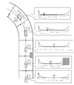
図1は本発明の実施形態に係る運転支援システムのハードウェア構成の一態様を示すブロック図である。
なお、本実施形態の車両は、その一態様として、カメラやGPS(Global Positioning System)と地図情報とを併用するなどして車両前方の道路情報を読み取る装置、自律的に操舵可能なステアリング装置、車体速度、換言すれば、走行速度の情報や、車両の走行状態,走行路面の摩擦係数μなどを推定するための情報が集まる横滑り防止装置などを有する車両である。 Hereinafter, embodiments of a driving support device, a driving support method, and a driving support system according to the present invention will be described based on the drawings.
FIG. 1 is a block diagram showing an aspect of a hardware configuration of a driving support system according to an embodiment of the present invention.
As one aspect of the vehicle according to the present embodiment, a device that reads road information ahead of the vehicle by using a camera or GPS (Global Positioning System) in combination with map information, a steering device that can steer autonomously, It is a vehicle having a side slip prevention device etc. where information for estimating the vehicle body speed, in other words, the traveling speed, the traveling state of the vehicle, and the friction coefficient μ of the traveling road surface is gathered.
車両1は、左前輪2,右前輪3,左後輪4,右後輪5を有した4輪車両であり、各車輪2-5は、ブレーキ装置を構成するホイルシリンダ6-9を具備する。
各ホイルシリンダ6-9の液圧は、横滑り防止装置に代表されるホイルシリンダ液圧制御装置10によって調整される。 Thevehicle 1 is a four-wheeled vehicle having a front left wheel 2, a front right wheel 3, a rear left wheel 4, and a rear right wheel 5, and each wheel 2-5 includes a wheel cylinder 6-9 that constitutes a brake device. .
The fluid pressure of each wheel cylinder 6-9 is adjusted by a wheel cylinder fluidpressure control device 10 represented by a skid prevention device.
各ホイルシリンダ6-9の液圧は、横滑り防止装置に代表されるホイルシリンダ液圧制御装置10によって調整される。 The
The fluid pressure of each wheel cylinder 6-9 is adjusted by a wheel cylinder fluid
エンジン11は、電子制御スロットルを具備するなどして出力トルクが電子制御される内燃機関である。
ステアリング装置12は、操舵アシスト力を発生するモータを備える電動パワーステアリング装置に代表される、操舵に関するアクチュエータを備えた自動操舵可能なステアリング装置である。 Theengine 11 is an internal combustion engine that has an electronically controlled throttle, etc., and the output torque is electronically controlled.
Thesteering device 12 is an automatically steerable steering device provided with an actuator related to steering, represented by an electric power steering device provided with a motor that generates a steering assist force.
ステアリング装置12は、操舵アシスト力を発生するモータを備える電動パワーステアリング装置に代表される、操舵に関するアクチュエータを備えた自動操舵可能なステアリング装置である。 The
The
外界認識コントロールユニット13は、マイクロコンピュータを備え、地図情報やカメラによる撮像情報を処理する外界認識部である。
第1運転支援コントロールユニットとしての行動戦略コントローラ14は、マイクロコンピュータを備え、外界認識コントロールユニット13により得られた外界情報が通信線を介して入力される。
前記通信線は、例えば、CAN(Controller Area Network)などの車載ネットワークである。 The external worldrecognition control unit 13 is an external world recognition unit that includes a microcomputer and processes map information and information captured by a camera.
Theaction strategy controller 14 as a first driving support control unit includes a microcomputer, and external world information obtained by the external world recognition control unit 13 is input through a communication line.
The communication line is, for example, an in-vehicle network such as CAN (Controller Area Network).
第1運転支援コントロールユニットとしての行動戦略コントローラ14は、マイクロコンピュータを備え、外界認識コントロールユニット13により得られた外界情報が通信線を介して入力される。
前記通信線は、例えば、CAN(Controller Area Network)などの車載ネットワークである。 The external world
The
The communication line is, for example, an in-vehicle network such as CAN (Controller Area Network).
そして、行動戦略コントローラ14は、入力した外界情報に基づいて、道路情報としての路端情報及び自車両の目標軌跡などを演算するのに加えて、自車両が走行幅から逸脱するリスクである車線逸脱リスクを演算し、目標軌跡に関する情報及び車線逸脱リスクに関する情報などを出力する。
つまり、行動戦略コントローラ14は、目標走行軌跡演算部及び逸脱リスク演算部としての機能を備える運転支援装置である。
なお、本願では、車線幅や障害物などを考慮した車両が走行可能な道路幅を、走行幅と称する。 Then, in addition to calculating the roadside information as the road information and the target trajectory of the own vehicle based on the input external world information, theaction strategy controller 14 is a risk that the own vehicle deviates from the traveling width. The departure risk is calculated, and information on the target trajectory and information on the lane departure risk are output.
That is, theaction strategy controller 14 is a driving assistance device having functions as a target travel locus calculation unit and a departure risk calculation unit.
In the present application, a road width on which a vehicle can travel in consideration of a lane width, an obstacle, and the like is referred to as a travel width.
つまり、行動戦略コントローラ14は、目標走行軌跡演算部及び逸脱リスク演算部としての機能を備える運転支援装置である。
なお、本願では、車線幅や障害物などを考慮した車両が走行可能な道路幅を、走行幅と称する。 Then, in addition to calculating the roadside information as the road information and the target trajectory of the own vehicle based on the input external world information, the
That is, the
In the present application, a road width on which a vehicle can travel in consideration of a lane width, an obstacle, and the like is referred to as a travel width.
第2運転支援コントロールユニットとしての運動戦略コントローラ15は、マイクロコンピュータを備え、行動戦略コントローラ14と通信線で接続され、行動戦略コントローラ14により演算された目標軌跡に関する情報及び車線逸脱リスクに関する情報などを入力する。
そして、運動戦略コントローラ15は、自車両の走行幅からの逸脱の抑止と、走行の安定化とが両立するように、目標軌跡に関する情報及び車線逸脱リスクに関する情報に基づき、ステアリング操作,エンジン出力,ブレーキ操作などの指令信号、換言すれば、操作量を演算して出力する。
つまり、運動戦略コントローラ15は、自車両の操舵、制駆動に関するアクチュエータの操作量に関する情報を求めるアクチュエータ操作量演算部としての機能を備える運転支援装置である。 Theexercise strategy controller 15 as a second driving support control unit includes a microcomputer, is connected to the action strategy controller 14 by a communication line, and information on the target trajectory calculated by the action strategy controller 14 and information on the lane departure risk etc. input.
Then, themotion strategy controller 15 performs steering operation, engine output, and the like based on the information on the target trajectory and the information on the lane departure risk so that the suppression of the departure from the travel width of the own vehicle and the stabilization of the travel are compatible. A command signal such as a brake operation, in other words, an operation amount is calculated and output.
That is, themotion strategy controller 15 is a driving support device having a function as an actuator operation amount calculation unit that obtains information on the operation amount of the actuator related to steering and braking of the host vehicle.
そして、運動戦略コントローラ15は、自車両の走行幅からの逸脱の抑止と、走行の安定化とが両立するように、目標軌跡に関する情報及び車線逸脱リスクに関する情報に基づき、ステアリング操作,エンジン出力,ブレーキ操作などの指令信号、換言すれば、操作量を演算して出力する。
つまり、運動戦略コントローラ15は、自車両の操舵、制駆動に関するアクチュエータの操作量に関する情報を求めるアクチュエータ操作量演算部としての機能を備える運転支援装置である。 The
Then, the
That is, the
図2は、行動戦略コントローラ14及び運動戦略コントローラ15を含む運転支援システム200の一態様を示す機能ブロック図である。
行動戦略コントローラ14は、目標走行軌跡演算部310、自車位置演算部320、前方注視点演算部330、路端情報演算部340、目標点座標演算部350、逸脱リスク演算部360としての機能を備える。 FIG. 2 is a functional block diagram illustrating an aspect of the driving support system 200 including theaction strategy controller 14 and the exercise strategy controller 15.
Theaction strategy controller 14 functions as a target travel locus calculation unit 310, a vehicle position calculation unit 320, a forward gaze point calculation unit 330, a roadside information calculation unit 340, a target point coordinate calculation unit 350, and a departure risk calculation unit 360. Prepare.
行動戦略コントローラ14は、目標走行軌跡演算部310、自車位置演算部320、前方注視点演算部330、路端情報演算部340、目標点座標演算部350、逸脱リスク演算部360としての機能を備える。 FIG. 2 is a functional block diagram illustrating an aspect of the driving support system 200 including the
The
目標走行軌跡演算部310は、外界認識コントロールユニット13により得られた外界認識情報を受け、自車両前方の道路形状や障害物などに基づき自車両の目標走行軌跡を演算する。
自車位置演算部320は、外界認識コントロールユニット13により得られた外界認識情報を受け、自車両の現在位置座標(Xv,Yv)を演算する。 The target travellocus calculation unit 310 receives the external world recognition information obtained by the external world recognition control unit 13 and calculates a target travel locus of the own vehicle based on the road shape in front of the own vehicle, an obstacle, and the like.
The host vehicleposition calculation unit 320 receives the external world recognition information obtained by the external world recognition control unit 13 and calculates current position coordinates (Xv, Yv) of the host vehicle.
自車位置演算部320は、外界認識コントロールユニット13により得られた外界認識情報を受け、自車両の現在位置座標(Xv,Yv)を演算する。 The target travel
The host vehicle
前方注視点演算部330は、自車位置演算部320が演算した現在位置座標(Xv,Yv)に基づき、所定時間後の自車両の位置を示す前方注視点(Xs,Ys)を演算する。
目標点座標演算部350は、前方注視点(Xs,Ys)から最も近い目標走行軌跡上の点である最近傍点を、目標点座標(Xp,Yp)として演算する。
路端情報演算部340は、外界認識コントロールユニット13により得られた外界認識情報を受け、車線幅や障害物などを考慮した車両が走行可能な路端情報を演算する。 The forward fixationpoint calculation unit 330 calculates forward fixation point (Xs, Ys) indicating the position of the own vehicle after a predetermined time based on the current position coordinates (Xv, Yv) calculated by the own vehicle position calculation unit 320.
The target pointcoordinate calculation unit 350 calculates, as the target point coordinates (Xp, Yp), a nearest point which is a point on the target travel locus closest to the forward fixation point (Xs, Ys).
The roadsideinformation calculation unit 340 receives the external world recognition information obtained by the external world recognition control unit 13 and calculates roadside information on which the vehicle can travel taking into consideration the lane width, obstacles, and the like.
目標点座標演算部350は、前方注視点(Xs,Ys)から最も近い目標走行軌跡上の点である最近傍点を、目標点座標(Xp,Yp)として演算する。
路端情報演算部340は、外界認識コントロールユニット13により得られた外界認識情報を受け、車線幅や障害物などを考慮した車両が走行可能な路端情報を演算する。 The forward fixation
The target point
The roadside
逸脱リスク演算部360は、前方注視点(Xs,Ys)や路端情報などから、逸脱リスクとして、道路左端から車両が逸脱するリスクである左路端逸脱リスクCORLと、道路右端から車両が逸脱するリスクである右路端逸脱リスクCORRをそれぞれ演算する。
なお、逸脱リスク演算部360は、車両が走行する走行幅からの逸脱リスクの分布に関する情報であるリスクマップを作成し、当該リスクマップを参照して前方注視点(Xs,Ys)に対応する逸脱リスクCORL、CORRを求める。 The departurerisk calculation unit 360 uses the left road end departure risk COR L , which is the risk that the vehicle deviates from the left end of the road, and the vehicle from the right end of the road as the departure risk from forward fixation point (Xs, Ys) and roadside information etc. The right road edge departure risk COR R which is the risk of departure is calculated respectively.
The departurerisk calculation unit 360 creates a risk map that is information on the distribution of the departure risk from the travel width in which the vehicle travels, and refers to the risk map to make a deviation corresponding to the forward gaze point (Xs, Ys). Find the risk COR L and COR R.
なお、逸脱リスク演算部360は、車両が走行する走行幅からの逸脱リスクの分布に関する情報であるリスクマップを作成し、当該リスクマップを参照して前方注視点(Xs,Ys)に対応する逸脱リスクCORL、CORRを求める。 The departure
The departure
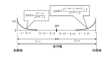
図3は、上記のリスクマップの基本的な特性の一態様を示す。
リスクマップは、左右の路端、換言すれば、障害物から距離が十分に離れた領域を最小リスクとし、左右の路端に近づくにしたがってリスクが指数関数的に増大するように作成され、左路端逸脱リスクCORL及び右路端逸脱リスクCORRの値は、走行幅からの逸脱が確定的な状況下では“1”に設定され、走行幅からの逸脱に至る危険性が最も低い場合は“0”になるように正規化される。
但し、左路端逸脱リスクCORL及び右路端逸脱リスクCORRの値とリスク度合いとの相関は任意に設定できる。
なお、リスクマップについては後で詳細に説明する。 FIG. 3 illustrates one aspect of the basic characteristics of the above-described risk map.
The risk map is created so that the left and right roadsides, in other words, the area far enough from the obstacle is the minimum risk, and the risk increases exponentially as the left and right roadsides approach, The values of roadside departure risk COR L and right road end departure risk COR R are set to “1” under the condition that departure from travel width is definite, and the risk of departure from travel width is the lowest. Is normalized to be "0".
However, the correlation between the values of the left road end departure risk COR L and the right road end departure risk COR R and the degree of risk can be set arbitrarily.
The risk map will be described in detail later.
一方、運動戦略コントローラ15は、行動戦略コントローラ14で演算された目標走行軌跡、目標点座標(Xp,Yp)、前方注視点(Xs,Ys)、左路端逸脱リスクCORL及び右路端逸脱リスクCORRに関する情報などを入力するとともに、車体速度取得部212により得られた車体速度Vcに関する情報、ヨーモーメント演算部221で演算された自車両の挙動を安定化させるためのヨーモーメントに関する情報などを入力する。
そして、運動戦略コントローラ15は、上記の入力情報に基づき、目標操舵量に関する情報、及び、目標ブレーキモーメントに関する情報を演算し、これらの演算結果を操舵量制御部501、液圧制御部502に出力する。
なお、本願において、ブレーキモーメントとは、ブレーキ制御で発生させる旋回モーメントを意味する。 On the other hand, themotion strategy controller 15 calculates the target travel locus calculated by the action strategy controller 14, target point coordinates (Xp, Yp), forward fixation point (Xs, Ys), left roadside departure risk COR L and right roadside departure Information on the risk COR R, information on the vehicle speed Vc obtained by the vehicle speed acquisition unit 212, information on the yaw moment for stabilizing the behavior of the vehicle calculated by the yaw moment calculation unit 221, etc. Enter
Then, themotion strategy controller 15 calculates the information on the target steering amount and the information on the target brake moment based on the above input information, and outputs these calculation results to the steering amount control unit 501 and the hydraulic pressure control unit 502. Do.
In the present application, the braking moment means a turning moment generated by the brake control.
そして、運動戦略コントローラ15は、上記の入力情報に基づき、目標操舵量に関する情報、及び、目標ブレーキモーメントに関する情報を演算し、これらの演算結果を操舵量制御部501、液圧制御部502に出力する。
なお、本願において、ブレーキモーメントとは、ブレーキ制御で発生させる旋回モーメントを意味する。 On the other hand, the
Then, the
In the present application, the braking moment means a turning moment generated by the brake control.
操舵量制御部501は、目標操舵量に応じた操作量に関する情報をステアリング装置12のアクチュエータに出力し、ステアリング装置12による操舵を制御する。
また、液圧制御部502は、ホイルシリンダ6-9それぞれに供給する液圧、つまり、各車輪に付与する制動力を目標ブレーキモーメントに応じて制御する。 The steeringamount control unit 501 outputs information on the operation amount according to the target steering amount to the actuator of the steering device 12 to control the steering by the steering device 12.
The fluidpressure control unit 502 controls the fluid pressure supplied to each of the wheel cylinders 6-9, that is, the braking force applied to each wheel according to the target brake moment.
また、液圧制御部502は、ホイルシリンダ6-9それぞれに供給する液圧、つまり、各車輪に付与する制動力を目標ブレーキモーメントに応じて制御する。 The steering
The fluid
運動戦略コントローラ15は、目標操舵量を演算するための機能として、F/F操作量演算部410、F/B操作量演算部420、F/F操作量補正部430、F/B操作量補正部440、目標操舵量演算部450を備える。
また、運動戦略コントローラ15は、目標ブレーキモーメントを演算するための機能として、ヨーモーメント補正部460、ブレーキモーメント演算部470を備える。 Themotion strategy controller 15 has a function for calculating a target steering amount, such as an F / F operation amount calculation unit 410, an F / B operation amount calculation unit 420, an F / F operation amount correction unit 430, and an F / B operation amount correction. The unit 440 includes a target steering amount calculation unit 450.
Themotion strategy controller 15 further includes a yaw moment correction unit 460 and a brake moment calculation unit 470 as functions for calculating the target brake moment.
また、運動戦略コントローラ15は、目標ブレーキモーメントを演算するための機能として、ヨーモーメント補正部460、ブレーキモーメント演算部470を備える。 The
The
図4のフローチャートは、行動戦略コントローラ14及び運動戦略コントローラ15を含む運転支援システム200による操舵操作量及びブレーキ操作量の演算処理の手順を概略的に示す。
まず、行動戦略コントローラ14の自車位置演算部320は、外界認識情報に基づいて現在位置座標(Xv,Yv)を演算し(ステップS1001)、次いで、行動戦略コントローラ14の前方注視点演算部330は、外界認識情報に基づいて前方注視点(Xs,Ys)を演算する(ステップS1002)。 The flowchart in FIG. 4 schematically shows the procedure of computing processing of the steering operation amount and the brake operation amount by the driving support system 200 including theaction strategy controller 14 and the movement strategy controller 15.
First, the vehicleposition calculation unit 320 of the action strategy controller 14 calculates current position coordinates (Xv, Yv) based on the external world recognition information (step S1001), and then the forward gaze point calculation unit 330 of the action strategy controller 14 The forward gaze point (Xs, Ys) is calculated based on the external world recognition information (step S 1002).
まず、行動戦略コントローラ14の自車位置演算部320は、外界認識情報に基づいて現在位置座標(Xv,Yv)を演算し(ステップS1001)、次いで、行動戦略コントローラ14の前方注視点演算部330は、外界認識情報に基づいて前方注視点(Xs,Ys)を演算する(ステップS1002)。 The flowchart in FIG. 4 schematically shows the procedure of computing processing of the steering operation amount and the brake operation amount by the driving support system 200 including the
First, the vehicle
更に、行動戦略コントローラ14の目標点座標演算部350は、前方注視点(Xs,Ys)と目標走行軌跡とに基づいて目標点座標(Xp,Yp)を演算する(ステップS1003)。
そして、運動戦略コントローラ15のF/F操作量演算部410は、車線追従のための旋回力のフィードフォワードF/F操作量FYFFを演算し(ステップS1004)、更に、運動戦略コントローラ15のF/B操作量演算部420は、車線追従のための旋回力のフィードバックF/B操作量FYFBを演算する(ステップS1005)。 Furthermore, the target point coordinatecalculation unit 350 of the action strategy controller 14 calculates target point coordinates (Xp, Yp) based on the forward fixation point (Xs, Ys) and the target travel locus (step S1003).
Then, the F / F manipulatedvariable computing unit 410 of the motion strategy controller 15 computes the feedforward F / F manipulated variable FY FF of the turning force for following the lane (step S 1004), and further, F of the motion strategy controller 15 The / B operation amount calculation unit 420 calculates feedback F / B operation amount FY FB of the turning force for following the lane (step S1005).
そして、運動戦略コントローラ15のF/F操作量演算部410は、車線追従のための旋回力のフィードフォワードF/F操作量FYFFを演算し(ステップS1004)、更に、運動戦略コントローラ15のF/B操作量演算部420は、車線追従のための旋回力のフィードバックF/B操作量FYFBを演算する(ステップS1005)。 Furthermore, the target point coordinate
Then, the F / F manipulated
次いで、運動戦略コントローラ15の目標操舵量演算部450は、フィードフォワードF/F操作量FYFFとフィードバックF/B操作量FYFBとの和FYVを、車線追従に必要な横力として演算する(ステップS1006)。
更に、目標操舵量演算部450は、車両の挙動安定化に必要なモーメントMvを演算し(ステップS1007)、目標の前輪横力FYfを演算し(ステップS1008)、目標の後輪横力FYrを演算する(ステップS1009)。 Then, the target steeringangle calculation section 450 of the motion strategy controller 15, the sum FY V with feedforward F / F operation amount FY FF and the feedback F / B operation amount FY FB, computed as the lateral force required for lane keeping (Step S1006).
Further, the target steeringamount calculation unit 450 calculates a moment Mv necessary for stabilizing the behavior of the vehicle (step S1007), calculates a target front wheel lateral force FYf (step S1008), and calculates a target rear wheel lateral force FYr. An operation is performed (step S1009).
更に、目標操舵量演算部450は、車両の挙動安定化に必要なモーメントMvを演算し(ステップS1007)、目標の前輪横力FYfを演算し(ステップS1008)、目標の後輪横力FYrを演算する(ステップS1009)。 Then, the target steering
Further, the target steering
そして、目標操舵量演算部450は、前輪横力FYfから操舵角度δを演算する(ステップS1010)。
また、運動戦略コントローラ15のブレーキモーメント演算部470は、自車両の車輪の接地路面の摩擦係数に応じて、達成可能な前輪横力を演算し(ステップS1011)、更に、達成可能な後輪横力を演算する(ステップS1012)。
次いで、ブレーキモーメント演算部470は、ブレーキ制御で発生させる旋回モーメントの目標値であるブレーキモーメントMBを演算し(ステップS1013)、更に、ブレーキモーメントMBに基づいて各車輪のブレーキ液圧を演算する(ステップS1014)。 Then, target steeringamount calculation unit 450 calculates steering angle δ from front wheel lateral force FYf (step S1010).
Further, the brakemoment calculation unit 470 of the motion strategy controller 15 calculates the achievable front wheel lateral force according to the friction coefficient of the ground contact surface of the wheels of the host vehicle (step S1011), and further, the achievable rear wheel lateral The force is calculated (step S1012).
Then, brakingtorque calculation unit 470 calculates the braking torque M B which is a target value of the turning moment to be generated by the brake control (step S1013), further calculates the brake fluid pressure of each based on the braking torque M B wheels (Step S1014).
また、運動戦略コントローラ15のブレーキモーメント演算部470は、自車両の車輪の接地路面の摩擦係数に応じて、達成可能な前輪横力を演算し(ステップS1011)、更に、達成可能な後輪横力を演算する(ステップS1012)。
次いで、ブレーキモーメント演算部470は、ブレーキ制御で発生させる旋回モーメントの目標値であるブレーキモーメントMBを演算し(ステップS1013)、更に、ブレーキモーメントMBに基づいて各車輪のブレーキ液圧を演算する(ステップS1014)。 Then, target steering
Further, the brake
Then, braking
以下では、運動戦略コントローラ15における目標操舵量の演算処理を詳細に説明する。
まず、F/F操作量演算部410は、目標点座標(Xp,Yp)におけるカーブの形状、車体速度Vc、及び、自車両の質量mに基づいて、自車両が前方のカーブを安定的に旋回走行するために必要な旋回力、換言すれば、車線追従のための旋回力のフィードフォワードF/F操作量FYFFを、数1にしたがって演算する(図4のステップS1004参照)。
なお、目標点座標(Xp,Yp)におけるカーブの形状とは、例えば、目標点座標(Xp,Yp)における道路曲率Ksなどである。

Below, the calculation processing of the target steering amount in the movement strategy controller 15 will be described in detail.
First, the F / F operationamount calculation unit 410 stably stabilizes the curve in front of the host vehicle based on the shape of the curve in the target point coordinates (Xp, Yp), the vehicle speed Vc, and the mass m of the host vehicle. A turning force necessary for turning, in other words, a feedforward F / F operation amount FY FF of the turning force for following a lane, is calculated according to Equation 1 (see step S1004 in FIG. 4).
The shape of the curve at the target point coordinates (Xp, Yp) is, for example, the road curvature Ks at the target point coordinates (Xp, Yp).
まず、F/F操作量演算部410は、目標点座標(Xp,Yp)におけるカーブの形状、車体速度Vc、及び、自車両の質量mに基づいて、自車両が前方のカーブを安定的に旋回走行するために必要な旋回力、換言すれば、車線追従のための旋回力のフィードフォワードF/F操作量FYFFを、数1にしたがって演算する(図4のステップS1004参照)。
なお、目標点座標(Xp,Yp)におけるカーブの形状とは、例えば、目標点座標(Xp,Yp)における道路曲率Ksなどである。
First, the F / F operation
The shape of the curve at the target point coordinates (Xp, Yp) is, for example, the road curvature Ks at the target point coordinates (Xp, Yp).
次に、F/B操作量演算部420は、目標点座標(Xp,Yp)と前方注視点(Xs,Ys)との距離GFBに基づき、例えば数2に示すように、偏差に基づくPID制御などを用いて、車線追従のための旋回力のフィードバックF/B操作量FYFBを演算する(図4のステップS1005参照)。

Next, the F / B manipulated variable computing unit 420 sets the PID based on the deviation, for example, as shown in Equation 2, based on the distance G FB between the target point coordinates (Xp, Yp) and the forward fixation point (Xs, Ys). using controls the calculates the feedback F / B operation amount FY FB of the turning force for lane keeping (see step S1005 of FIG. 4).
そして、目標操舵量演算部450は、F/F操作量演算部410で演算されたフィードフォワードF/F操作量FYFF、F/B操作量演算部420で演算されたフィードバックF/B操作量FYFB、及び、ヨーモーメント演算部221で演算された車両挙動安定化ヨーモーメントMstに基づいて、以下のようにして目標操舵量を演算する。
なお、目標操舵量演算部450が目標操舵量の演算に用いるフィードフォワードF/F操作量FYFF、フィードバックF/B操作量FYFB、及び車両挙動安定化ヨーモーメントMstは、後述するように、自車両の走行幅からの逸脱リスクに基づいて補正された値であるが、逸脱リスクに基づく補正処理については後で詳述する。 Then, the target steeringamount calculation unit 450 calculates the feedforward F / F operation amount FY FF calculated by the F / F operation amount calculation unit 410 and the feedback F / B operation amount calculated by the F / B operation amount calculation unit 420. Based on FY FB and the vehicle behavior stabilization yaw moment Mst calculated by the yaw moment calculation unit 221, the target steering amount is calculated as follows.
Incidentally, feedforward F / F operation amount target steeringangle calculation section 450 is used for calculation of the target steering amount FY FF, feedback F / B operation amount FY FB, and the vehicle behavior stabilization yaw moment Mst, as described later, Although the value is corrected based on the risk of departure from the travel width of the host vehicle, the correction processing based on the risk of departure will be described in detail later.
なお、目標操舵量演算部450が目標操舵量の演算に用いるフィードフォワードF/F操作量FYFF、フィードバックF/B操作量FYFB、及び車両挙動安定化ヨーモーメントMstは、後述するように、自車両の走行幅からの逸脱リスクに基づいて補正された値であるが、逸脱リスクに基づく補正処理については後で詳述する。 Then, the target steering
Incidentally, feedforward F / F operation amount target steering
まず、目標操舵量演算部450は、フィードフォワードF/F操作量FYFFとフィードバックF/B操作量FYFBとの和FYV(FYV=FYFF+FYFB)を、自車両を現在位置座標(Xv,Yv)から目標点座標(Xp,Yp)に到達させるために必要な横力として演算する(図4のステップS1006参照)。
また、目標操舵量演算部450は、横力FYVを車両に与えたときに発生するヨーモーメントMLを、数3の伝達関数にしたがって演算する。 First, the target steeringamount calculation unit 450 calculates the sum FY V (FY V = FY FF + FY FB ) of the feedforward F / F operation amount FY FF and the feedback F / B operation amount FB, and sets the vehicle to the current position coordinates. The lateral force required to reach the target point coordinates (Xp, Yp) from (Xv, Yv) is calculated (see step S1006 in FIG. 4).
Further, the target steeringangle calculation section 450, a yaw moment ML that generates a lateral force FY V when given to the vehicle is calculated according to the number 3 of the transfer function.
また、目標操舵量演算部450は、横力FYVを車両に与えたときに発生するヨーモーメントMLを、数3の伝達関数にしたがって演算する。 First, the target steering
Further, the target steering

但し、数3におけるGr(0)、Gβ(0)、Tr、Tβは、数4に示すように定義される。

However, Gr (0), Gβ (0), Tr, and Tβ in Expression 3 are defined as shown in Expression 4.
また、ヨーモーメント演算部221から車両挙動安定化ヨーモーメントMstが与えられるとき、自車両が車両挙動を安定化しつつ前方の車線を好適に走行するための運動は、以下の数5で記述可能である(図4のステップS1007参照)。
但し、数5において、FYfは前輪2輪の横力合力、FYrは後輪2輪の横力合力である。

In addition, when the vehicle behavior stabilization yaw moment Mst is given from the yaw moment computation unit 221, the motion for suitably traveling the lane ahead while the vehicle stabilizes the vehicle behavior can be described by the following equation 5 (See step S1007 in FIG. 4).
However, inequation 5, FYf is the lateral force resultant of the two front wheels, and FYr is the lateral force of the two rear wheels.
但し、数5において、FYfは前輪2輪の横力合力、FYrは後輪2輪の横力合力である。
However, in
上記数5を整理すると、下記数6が得られる(図4のステップS1008、ステップS1009参照)。

If the above equation 5 is rearranged, the following equation 6 is obtained (see step S1008 and step S1009 in FIG. 4).
そして、目標操舵量演算部450は、数6にしたがって演算した前輪横力FYfに基づいて、操舵角度δを数7にしたがって演算する(図4のステップS1010参照)。
但し、βは横滑り角度、γはヨーレートである。

目標操舵量演算部450により得られた操舵角度δに関する情報は操舵量制御部501に与えられ、アクチュエータ操作出力部としての操舵量制御部501は、車両の操舵に関するアクチュエータであるステアリング装置12において操舵力を発生するモータを、操舵角度δに関する情報に基づいて駆動し、車両の舵角を目標の操舵角度δに制御する。
Then, target steering amount calculation unit 450 calculates steering angle δ according to Expression 7 based on front wheel lateral force FYf calculated according to Expression 6 (see step S1010 in FIG. 4).
Where β is a side slip angle and γ is a yaw rate.
The information on the steering angle δ obtained by the target steering amount calculation unit 450 is given to the steering amount control unit 501, and the steering amount control unit 501 as an actuator operation output unit performs steering in the steering device 12 which is an actuator related to steering of the vehicle. The motor generating the force is driven based on the information on the steering angle δ, and the steering angle of the vehicle is controlled to the target steering angle δ.
但し、βは横滑り角度、γはヨーレートである。
Where β is a side slip angle and γ is a yaw rate.
次に、運動戦略コントローラ15におけるブレーキモーメント演算部470の機能を説明する。
目標操舵量演算部450が演算した目標操舵角度に基づいて操舵が行われたとしても、路面摩擦力による制約などによって、目標操舵角度から期待される横力が発生しない場合がある。
この場合、路面摩擦力は物理的な制約であるため、操舵による横力不足を完全に補うことはできないが、ブレーキモーメント演算部470は、実際に達成可能な前後輪横力FYfμ,FYrμを演算し、係る前後輪横力FYfμ,FYrμに基づいて、車両モーメントの不足分を補うためのブレーキモーメントを演算する。 Next, the function of the brakemoment calculation unit 470 in the motion strategy controller 15 will be described.
Even if steering is performed based on the target steering angle calculated by the target steeringamount calculation unit 450, lateral force expected from the target steering angle may not occur due to a restriction due to road surface frictional force or the like.
In this case, since the road surface frictional force is a physical restriction, the lateral force shortage due to steering can not be completely compensated, but the brakemoment calculation unit 470 calculates the actually achievable front and rear wheel lateral forces FYfμ and FYrμ. Then, based on the front and rear wheel lateral forces FYfμ and FYrμ, a brake moment for compensating for the shortage of the vehicle moment is calculated.
目標操舵量演算部450が演算した目標操舵角度に基づいて操舵が行われたとしても、路面摩擦力による制約などによって、目標操舵角度から期待される横力が発生しない場合がある。
この場合、路面摩擦力は物理的な制約であるため、操舵による横力不足を完全に補うことはできないが、ブレーキモーメント演算部470は、実際に達成可能な前後輪横力FYfμ,FYrμを演算し、係る前後輪横力FYfμ,FYrμに基づいて、車両モーメントの不足分を補うためのブレーキモーメントを演算する。 Next, the function of the brake
Even if steering is performed based on the target steering angle calculated by the target steering
In this case, since the road surface frictional force is a physical restriction, the lateral force shortage due to steering can not be completely compensated, but the brake
図5のフローチャートは、ブレーキモーメント演算部470が前輪横力FYfμを演算する手順(図4のステップS1011の詳細)を示す。
まず、ブレーキモーメント演算部470は、ステップS711で、前輪横力FYfが正の値であるか否かに基づいて右旋回状態であるか否かを判断する。 The flowchart of FIG. 5 shows a procedure (details of step S1011 of FIG. 4) in which thebrake moment calculator 470 calculates the front wheel lateral force FYfμ.
First, in step S711, the brakemoment calculation unit 470 determines whether the vehicle is turning to the right based on whether the front wheel lateral force FYf is a positive value.
まず、ブレーキモーメント演算部470は、ステップS711で、前輪横力FYfが正の値であるか否かに基づいて右旋回状態であるか否かを判断する。 The flowchart of FIG. 5 shows a procedure (details of step S1011 of FIG. 4) in which the
First, in step S711, the brake
そして、FYf>0であって右旋回状態であるとき、ブレーキモーメント演算部470は、ステップS712に進み、下式にしたがって前輪横力FYfμを演算する。
FYfμ=min(μ・(WFL+WFR),FYf)
なお、上式において、WFL、WFRは、左右の前輪それぞれの荷重である。
そして、ブレーキモーメント演算部470は、上式にしたがって、“μ・(WFL+WFR)”と前輪横力FYfとの小さい方を実際に達成可能な前輪横力FYfμに設定する。 When FYf> 0 and the vehicle is turning to the right, the brakemoment calculation unit 470 proceeds to step S712 and calculates the front wheel lateral force FYfμ according to the following equation.
FYf μ = min (μ · (W FL + W FR ), FY f)
In the above equation, W FL and W FR are the loads of the left and right front wheels, respectively.
Then, according to the above equation, the brakemoment calculation unit 470 sets the smaller one of “μ · (W FL + W FR )” and the front wheel lateral force FYf to the actually achievable front wheel lateral force FYfμ.
FYfμ=min(μ・(WFL+WFR),FYf)
なお、上式において、WFL、WFRは、左右の前輪それぞれの荷重である。
そして、ブレーキモーメント演算部470は、上式にしたがって、“μ・(WFL+WFR)”と前輪横力FYfとの小さい方を実際に達成可能な前輪横力FYfμに設定する。 When FYf> 0 and the vehicle is turning to the right, the brake
FYf μ = min (μ · (W FL + W FR ), FY f)
In the above equation, W FL and W FR are the loads of the left and right front wheels, respectively.
Then, according to the above equation, the brake
一方、FYf≦0であって左旋回状態であるとき、ブレーキモーメント演算部470は、ステップS713に進み、下式にしたがって前輪横力FYfμを演算する。
FYfμ=max(-μ・(WFL+WFR),FYf)
つまり、ブレーキモーメント演算部470は、FYf≦0である左旋回状態のときに、“-μ・(WFL+WFR)”と前輪横力FYfとのうちの絶対値の小さい方を実際に達成可能な前輪横力FYfμに設定する。 On the other hand, when FYf ≦ 0 and the vehicle is turning left, the brakemoment calculation unit 470 proceeds to step S713 and calculates the front wheel lateral force FYfμ according to the following equation.
FY f μ = max (-μ · (W FL + W FR ), FY f)
That is, in the left turn state where FYf ≦ 0, the brakemoment calculation unit 470 actually sets the smaller one of “−μ · (W FL + W FR )” and the front wheel lateral force FYf to a smaller one. Set to the achievable front wheel lateral force FYfμ.
FYfμ=max(-μ・(WFL+WFR),FYf)
つまり、ブレーキモーメント演算部470は、FYf≦0である左旋回状態のときに、“-μ・(WFL+WFR)”と前輪横力FYfとのうちの絶対値の小さい方を実際に達成可能な前輪横力FYfμに設定する。 On the other hand, when FYf ≦ 0 and the vehicle is turning left, the brake
FY f μ = max (-μ · (W FL + W FR ), FY f)
That is, in the left turn state where FYf ≦ 0, the brake
図6のフローチャートは、ブレーキモーメント演算部470が後輪横力FYrμを演算する手順(図4のステップS1012の詳細)を示す。
まず、ブレーキモーメント演算部470は、ステップS721で、後輪横力FYrが正の値であるか否かに基づいて右旋回状態であるか否かを判断する。 The flowchart of FIG. 6 shows the procedure for thebrake moment calculator 470 to calculate the rear wheel lateral force FYrμ (details of step S1012 of FIG. 4).
First, in step S 721, the brakemoment calculation unit 470 determines whether or not the vehicle is turning to the right based on whether or not the rear wheel lateral force FYr is a positive value.
まず、ブレーキモーメント演算部470は、ステップS721で、後輪横力FYrが正の値であるか否かに基づいて右旋回状態であるか否かを判断する。 The flowchart of FIG. 6 shows the procedure for the
First, in step S 721, the brake
そして、FYr>0であって右旋回状態であるとき、ブレーキモーメント演算部470は、ステップS722に進み、下式にしたがって後輪横力FYrμを演算する。
FYrμ=min(μ・(WRL+WRR),FYr)
なお、上式において、WRL、WRRは、左右の後輪それぞれの荷重である。
そして、ブレーキモーメント演算部470は、上式にしたがって、“μ・(WRL+WRR)”と後輪横力FYrとの小さい方を実際に達成可能な後輪横力FYrμに設定する。 Then, when FYr> 0 and the vehicle is turning right, the brakemoment calculation unit 470 proceeds to step S722 and calculates the rear wheel lateral force FYrμ according to the following equation.
FYrμ = min (μ · (W RL + W RR ), FYr)
In the above equation, W RL and W RR are the loads of the left and right rear wheels, respectively.
Then, in accordance with the above equation, the brakemoment calculation unit 470 sets the smaller one of “μ · (W RL + W RR )” and the rear wheel lateral force FYr to the actually attainable rear wheel lateral force FYrμ.
FYrμ=min(μ・(WRL+WRR),FYr)
なお、上式において、WRL、WRRは、左右の後輪それぞれの荷重である。
そして、ブレーキモーメント演算部470は、上式にしたがって、“μ・(WRL+WRR)”と後輪横力FYrとの小さい方を実際に達成可能な後輪横力FYrμに設定する。 Then, when FYr> 0 and the vehicle is turning right, the brake
FYrμ = min (μ · (W RL + W RR ), FYr)
In the above equation, W RL and W RR are the loads of the left and right rear wheels, respectively.
Then, in accordance with the above equation, the brake
一方、FYr≦0であって左旋回状態であるとき、ブレーキモーメント演算部470は、ステップS723に進み、下式にしたがって後輪横力FYrμを演算する。
FYrμ=max(-μ・(WRL+WRR),FYr)
つまり、ブレーキモーメント演算部470は、FYr≦0である左旋回状態のときに、“-μ・(WRL+WRR)”と後輪横力FYrとのうちの絶対値の小さい方を実際に達成可能な後輪横力FYrμに設定する。 On the other hand, when FYR ≦ 0 and the vehicle is turning left, the brakemoment calculation unit 470 proceeds to step S723 and calculates the rear wheel lateral force FYrμ according to the following equation.
FYrμ = max (-μ · (W RL + W RR ), FYr)
That is, the brakemoment calculation unit 470 actually sets the smaller one of the absolute value of “−μ · (W RL + W RR )” and the rear wheel lateral force FYr in the left turn state where FYr ≦ 0. Set to the attainable rear wheel lateral force FYrμ.
FYrμ=max(-μ・(WRL+WRR),FYr)
つまり、ブレーキモーメント演算部470は、FYr≦0である左旋回状態のときに、“-μ・(WRL+WRR)”と後輪横力FYrとのうちの絶対値の小さい方を実際に達成可能な後輪横力FYrμに設定する。 On the other hand, when FYR ≦ 0 and the vehicle is turning left, the brake
FYrμ = max (-μ · (W RL + W RR ), FYr)
That is, the brake
ブレーキモーメント演算部470は、上記のようにして前後輪横力FYfμ,FYrμを求めると、次いで、前後輪横力FYfμ,FYrμ、重心点と前軸との距離Lf、及び、重心点と後前軸との距離Lrに基づいて、路面摩擦力により制限された前後輪の横力合力により発生するモーメントMacを下式にしたがって演算し、更に、モーメントMac及びモーメントMv(Mv=ML+Mst)に基づいてブレーキモーメントMBを演算する(図4のステップS1011参照)。
Mac=Lf・FYfμ-Lr・FYrμ
MB=Mv-Mac When the brakemoment calculation unit 470 determines the front and rear wheel lateral forces FYfμ and FYrμ as described above, next, the front and rear wheel lateral forces FYfμ and FYrμ, the distance Lf between the center of gravity and the front axis, and the center of gravity to the rear front Based on the distance Lr to the axis, the moment Mac generated by the lateral force combined force of the front and rear wheels restricted by road surface friction is calculated according to the following equation, and further based on the moment Mac and the moment Mv (Mv = ML + Mst) calculating a braking torque M B (see step S1011 of FIG. 4).
Mac = Lf · FYfμ-Lr · FYrμ
M B = Mv-Mac
Mac=Lf・FYfμ-Lr・FYrμ
MB=Mv-Mac When the brake
Mac = Lf · FYfμ-Lr · FYrμ
M B = Mv-Mac
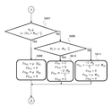
更に、ブレーキモーメント演算部470は、図7及び図8のフローチャートに示すような手順(図4のステップS1014の詳細)にしたがって、ブレーキモーメントMBを前輪と後輪のブレーキ液圧PFL、PFR、PRL、PRRに配分する。
なお、図7及び図8のフローチャートにおいて、Rはタイヤ動半径、KPfは前輪ブレーキ液圧変換係数、KPrは後輪ブレーキ液圧変換係数、Trはトレッド幅である。 Furthermore, brakingtorque calculation unit 470, according to the procedure (details of step S1014 in Fig. 4) as shown in the flowchart of FIG. 7 and FIG. 8, the brake torque M B brake fluid pressure of the front wheel and rear wheel P FL, P Allocate to FR , P RL and P RR .
In the flowcharts of FIGS. 7 and 8, R is a tire moving radius, KPf is a front wheel brake hydraulic pressure conversion coefficient, KPr is a rear wheel brake hydraulic pressure conversion coefficient, and Tr is a tread width.
なお、図7及び図8のフローチャートにおいて、Rはタイヤ動半径、KPfは前輪ブレーキ液圧変換係数、KPrは後輪ブレーキ液圧変換係数、Trはトレッド幅である。 Furthermore, braking
In the flowcharts of FIGS. 7 and 8, R is a tire moving radius, KPf is a front wheel brake hydraulic pressure conversion coefficient, KPr is a rear wheel brake hydraulic pressure conversion coefficient, and Tr is a tread width.
ブレーキモーメント演算部470は、まず、ステップS801で、ブレーキモーメントMBが正の値であるか否かに基づいて、ブレーキモーメントMBが右旋回モーメントであるか否かを判断する。
そして、ブレーキモーメントMBが右旋回モーメントである場合、ブレーキモーメント演算部470は、ステップS802に進み、ブレーキモーメントMBが“μ・(WFR+WRR)・Tr/2”以上であるか否か、つまり、ブレーキモーメントMBが、路面摩擦力により制限された右前輪の制動力及び右後輪の制動力で得られる右旋回モーメント以上であるか否かを判断する。 Brakingtorque computing unit 470, first, in step S801, based on whether the braking torque M B is a positive value, the brake torque M B determines whether a right turn moment.
When braking torque M B is a right turn moment, brakingtorque calculation unit 470 proceeds to step S802, the is braking torque M B is "μ · (W FR + W RR) · Tr / 2" or more whether, that is, braking torque M B determines whether it is limited right front wheel braking force and the right turning moment than that obtained by the braking force of the right rear wheel by road friction force.
そして、ブレーキモーメントMBが右旋回モーメントである場合、ブレーキモーメント演算部470は、ステップS802に進み、ブレーキモーメントMBが“μ・(WFR+WRR)・Tr/2”以上であるか否か、つまり、ブレーキモーメントMBが、路面摩擦力により制限された右前輪の制動力及び右後輪の制動力で得られる右旋回モーメント以上であるか否かを判断する。 Braking
When braking torque M B is a right turn moment, braking
ここで、ブレーキモーメントMBが“μ・(WFR+WRR)・Tr/2”以上である場合、ブレーキモーメント演算部470は、ステップS803に進み、各タイヤに発生する前後方向の力である前後輪の制駆動力FxFL、FxFR、FxRL、FxRRを以下のように設定する。
FxFL=0
FxFR=μ・WFR
FxRL=0
FxRR=μ・WRR
つまり、ブレーキモーメント演算部470は、ステップS803で、路面摩擦力で制限される制駆動力を右前輪、右後輪の目標に設定し、路面摩擦力で制限される右旋回モーメント(右旋回モーメント<ブレーキモーメントMB)を発生させるようにする。 Here, if it is braking torque M B is "μ · (W FR + W RR) · Tr / 2" or more, the braketorque computing unit 470 in the front-rear direction of the force flow proceeds to step S803, generated on each tire The braking / driving forces Fx FL , Fx FR , Fx RL , Fx RR of certain front and rear wheels are set as follows.
Fx FL = 0
Fx FR = μ · W FR
Fx RL = 0
Fx RR = μ · W RR
That is, in step S803, the brakemoment calculation unit 470 sets the braking / driving force limited by the road surface friction force as the target of the right front wheel and the right rear wheel, and the right turn moment (right turn It is made to generate a turning moment <braking moment M B ).
FxFL=0
FxFR=μ・WFR
FxRL=0
FxRR=μ・WRR
つまり、ブレーキモーメント演算部470は、ステップS803で、路面摩擦力で制限される制駆動力を右前輪、右後輪の目標に設定し、路面摩擦力で制限される右旋回モーメント(右旋回モーメント<ブレーキモーメントMB)を発生させるようにする。 Here, if it is braking torque M B is "μ · (W FR + W RR) · Tr / 2" or more, the brake
Fx FL = 0
Fx FR = μ · W FR
Fx RL = 0
Fx RR = μ · W RR
That is, in step S803, the brake
一方、ブレーキモーメントMBが“μ・(WFR+WRR)・Tr/2”未満で、路面摩擦力で制限されることなくブレーキモーメントMBを発生させることが可能である場合、ブレーキモーメント演算部470は、ステップS802からステップS804に進む。
ブレーキモーメント演算部470は、ステップS804で、ブレーキモーメントMBが“μ・WRR・Tr/2”以下であるか否かを判断する。 On the other hand, if the braking torque M B is less than "μ · (W FR + W RR) · Tr / 2", it is possible to generate a braking torque M B without being restricted by the road surface friction force, brakingtorque Operation unit 470 proceeds from step S802 to step S804.
Brakingtorque computing unit 470, at step S804, the determining whether the brake moment M B is equal to or less than "μ · W RR · Tr / 2".
ブレーキモーメント演算部470は、ステップS804で、ブレーキモーメントMBが“μ・WRR・Tr/2”以下であるか否かを判断する。 On the other hand, if the braking torque M B is less than "μ · (W FR + W RR) · Tr / 2", it is possible to generate a braking torque M B without being restricted by the road surface friction force, braking
Braking
ブレーキモーメントMBが“μ・WRR・Tr/2”以下である場合、要求される右旋回モーメントを右後輪の制動のみで得ることができるので、ブレーキモーメント演算部470は、ステップS805に進み、前後輪の制駆動力FxFL、FxFR、FxRL、FxRRを以下のように設定する。
FxFL=0
FxFR=0
FxRL=0
FxRR=2・MB/Tr If braking torque M B is equal to or less than "μ · W RR · Tr / 2", it is possible to obtain a right turn moment required of the right rear wheel brake only, the braketorque computing unit 470, step S805 Go to and set the braking / driving forces Fx FL , Fx FR , Fx RL , Fx RR of the front and rear wheels as follows.
Fx FL = 0
Fx FR = 0
Fx RL = 0
Fx RR = 2 · M B / Tr
FxFL=0
FxFR=0
FxRL=0
FxRR=2・MB/Tr If braking torque M B is equal to or less than "μ · W RR · Tr / 2", it is possible to obtain a right turn moment required of the right rear wheel brake only, the brake
Fx FL = 0
Fx FR = 0
Fx RL = 0
Fx RR = 2 · M B / Tr
一方、ブレーキモーメントMBが“μ・WRR・Tr/2”を超える場合、路面摩擦力による制限によって、右後輪の制動のみでは要求される右旋回モーメントを得ることができない状態であるので、ブレーキモーメント演算部470は、ステップS806に進み、前後輪の制駆動力FxFL、FxFR、FxRL、FxRRを以下のように設定する。
FxFL=0
FxFR=2・MB/Tr-μ・WRR
FxRL=0
FxRR=μ・WRR
つまり、ブレーキモーメント演算部470は、ステップS806で、右後輪に路面摩擦力で制限される制駆動力を与えるよう設定した上で、要求される右旋回モーメントを得るのに不足する分を、右前輪の制駆動力に設定する。 On the other hand, if it exceeds brake moment M B is "μ · W RR · Tr / 2", the restriction due to the road surface friction force, the only braking of the right rear wheel is in a state that can not be obtained right turn moment required Therefore, the brakemoment calculation unit 470 proceeds to step S806, and sets the front / rear wheel braking / driving forces Fx FL , Fx FR , Fx RL , and Fx RR as follows.
Fx FL = 0
Fx FR = 2 · M B / Tr-μ · W RR
Fx RL = 0
Fx RR = μ · W RR
That is, in step S806, the brakemoment calculation unit 470 is set to apply the braking / driving force limited by the road surface friction force to the right rear wheel, and then the insufficient amount to obtain the required right turning moment , Set to the braking and driving force of the right front wheel.
FxFL=0
FxFR=2・MB/Tr-μ・WRR
FxRL=0
FxRR=μ・WRR
つまり、ブレーキモーメント演算部470は、ステップS806で、右後輪に路面摩擦力で制限される制駆動力を与えるよう設定した上で、要求される右旋回モーメントを得るのに不足する分を、右前輪の制駆動力に設定する。 On the other hand, if it exceeds brake moment M B is "μ · W RR · Tr / 2", the restriction due to the road surface friction force, the only braking of the right rear wheel is in a state that can not be obtained right turn moment required Therefore, the brake
Fx FL = 0
Fx FR = 2 · M B / Tr-μ · W RR
Fx RL = 0
Fx RR = μ · W RR
That is, in step S806, the brake
また、ブレーキモーメント演算部470は、ステップS801で、ブレーキモーメントMBが正の値ではないと判断した場合、つまり、ブレーキモーメントMBが0であるか又は左旋回モーメントである場合、ステップS807に進む。
ブレーキモーメント演算部470は、ステップS807で、ブレーキモーメントMB(MB≦0)が“-μ・(WFL+WRL)・Tr/2”以下であるか否か、換言すれば、ブレーキモーメントMBの絶対値が“μ・(WFL+WRL)・Tr/2”以上であるか否かを判断する。 The brakemoment calculating unit 470, at step S801, if it is determined that the braking torque M B is not the positive value, that is, when braking torque M B is or left turn moment or is 0, the step S807 move on.
In step S807, the brakemoment calculation unit 470 determines whether the brake moment M B (M B ≦ 0) is “−μ · (W FL + W RL ) · Tr / 2” or less, in other words, the brake moment the absolute value of M B is "μ · (W FL + W RL) · Tr / 2" determines the whether or.
ブレーキモーメント演算部470は、ステップS807で、ブレーキモーメントMB(MB≦0)が“-μ・(WFL+WRL)・Tr/2”以下であるか否か、換言すれば、ブレーキモーメントMBの絶対値が“μ・(WFL+WRL)・Tr/2”以上であるか否かを判断する。 The brake
In step S807, the brake
ここで、ブレーキモーメントMBが“-μ・(WFL+WRL)・Tr/2”以下である場合、ブレーキモーメント演算部470は、ステップS808に進み、前後輪の制駆動力FxFL、FxFR、FxRL、FxRRを以下のように設定する。
FxFL=μ・WFL
FxFR=0
FxRL=μ・WRL
FxRR=0
つまり、ブレーキモーメント演算部470は、路面摩擦力で制限される制駆動力を左前輪、左後輪の目標に設定し、路面摩擦力で制限される左旋回モーメントを発生させるようにする。 Here, if the braking torque M B is equal to or less than "-μ · (W FL + W RL) · Tr / 2", the braketorque computing unit 470 proceeds to step S808, longitudinal force Fx FL of the front and rear wheels, Set Fx FR , Fx RL and Fx RR as follows.
Fx FL = μ · W FL
Fx FR = 0
Fx RL = μ · W RL
Fx RR = 0
That is, the brakemoment calculation unit 470 sets the braking / driving force limited by the road surface frictional force as the target of the left front wheel and the left rear wheel, and generates a left turning moment limited by the road surface frictional force.
FxFL=μ・WFL
FxFR=0
FxRL=μ・WRL
FxRR=0
つまり、ブレーキモーメント演算部470は、路面摩擦力で制限される制駆動力を左前輪、左後輪の目標に設定し、路面摩擦力で制限される左旋回モーメントを発生させるようにする。 Here, if the braking torque M B is equal to or less than "-μ · (W FL + W RL) · Tr / 2", the brake
Fx FL = μ · W FL
Fx FR = 0
Fx RL = μ · W RL
Fx RR = 0
That is, the brake
一方、ブレーキモーメントMBが“-μ・(WFL+WRL)・Tr/2”よりも高い場合、つまり、ブレーキモーメントMBの絶対値が“μ・(WFL+WRL)・Tr/2”よりも小さく、路面摩擦力で制限されることなくブレーキモーメントMBを発生させることが可能である場合、ブレーキモーメント演算部470は、ステップS807からステップS809に進む。
ブレーキモーメント演算部470は、ステップS809で、ブレーキモーメントMBが“-μ・WRL・Tr/2”以上であるか否かを判断する。 On the other hand, is higher than the braking torque M B is "-μ · (W FL + W RL) · Tr / 2", that is, the absolute value of "μ · (W FL + W RL) of the brake moment M B · Tr / 2 less than ", if it is possible to generate a braking torque M B without being restricted by the road surface friction force, braketorque computing unit 470 proceeds from step S807 to step S809.
Brakingtorque computing unit 470, at step S809, it is determined whether a braking torque M B is "-μ · W RL · Tr / 2" or more.
ブレーキモーメント演算部470は、ステップS809で、ブレーキモーメントMBが“-μ・WRL・Tr/2”以上であるか否かを判断する。 On the other hand, is higher than the braking torque M B is "-μ · (W FL + W RL) · Tr / 2", that is, the absolute value of "μ · (W FL + W RL) of the brake moment M B · Tr / 2 less than ", if it is possible to generate a braking torque M B without being restricted by the road surface friction force, brake
Braking
ブレーキモーメントMBが“-μ・WRL・Tr/2”以上である場合、要求される左旋回モーメントを左後輪の制動のみで得ることができるので、ブレーキモーメント演算部470は、ステップS810に進み、前後輪の制駆動力FxFL、FxFR、FxRL、FxRRを以下のように設定する。
FxFL=0
FxFR=0
FxRL=-2・MB/Tr
FxRR=0
なお、“FxRL=-2・MB/Tr”におけるマイナス符号は、負の値であるブレーキモーメントMBから正の制駆動力を求めることを意味する。 If it is braking torque M B is "-μ · W RL · Tr / 2" or more, since a left turn moment is required can be obtained only in the braking of the left rear wheel brakemoment calculation unit 470, step S810 Go to and set the braking / driving forces Fx FL , Fx FR , Fx RL , Fx RR of the front and rear wheels as follows.
Fx FL = 0
Fx FR = 0
Fx RL = −2 · M B / Tr
Fx RR = 0
The minus sign in “Fx RL = −2 · M B / Tr” means that a positive braking / driving force is obtained from the brake moment M B which is a negative value.
FxFL=0
FxFR=0
FxRL=-2・MB/Tr
FxRR=0
なお、“FxRL=-2・MB/Tr”におけるマイナス符号は、負の値であるブレーキモーメントMBから正の制駆動力を求めることを意味する。 If it is braking torque M B is "-μ · W RL · Tr / 2" or more, since a left turn moment is required can be obtained only in the braking of the left rear wheel brake
Fx FL = 0
Fx FR = 0
Fx RL = −2 · M B / Tr
Fx RR = 0
The minus sign in “Fx RL = −2 · M B / Tr” means that a positive braking / driving force is obtained from the brake moment M B which is a negative value.
一方、ブレーキモーメントMBが“-μ・WRL・Tr/2”よりも小さい場合、路面摩擦力による制限によって、左後輪の制動のみでは要求される左旋回モーメントを得ることができない状態であるので、ブレーキモーメント演算部470は、ステップS811に進み、前後輪の制駆動力FxFL、FxFR、FxRL、FxRRを以下のように設定する。
FxFL=-2・MB/Tr+μ・WRL
FxFR=0
FxRL=μ・WRL
FxRR=0
つまり、ブレーキモーメント演算部470は、ステップS811で、左後輪に路面摩擦力で制限される制駆動力を与えるよう設定した上で、要求される左旋回モーメントを得るのに不足する分を、左前輪の制駆動力に設定する。 On the other hand, if the braking torque M B is smaller than "-μ · W RL · Tr / 2", the restriction due to the road surface friction force, the only braking of the left rear wheel in a state that can not be obtained left turn moment required Since the brakemoment calculation unit 470 proceeds to step S811, the braking moment calculation unit 470 sets the braking / driving forces Fx FL , Fx FR , Fx RL , and Fx RR of the front and rear wheels as follows.
Fx FL = −2 · M B / Tr + μ · W RL
Fx FR = 0
Fx RL = μ · W RL
Fx RR = 0
That is, after setting the brakingmoment calculation unit 470 to apply the braking / driving force limited by the road surface friction force to the left rear wheel in step S811, the portion lacking for obtaining the required left turning moment is Set to the braking and driving force of the left front wheel.
FxFL=-2・MB/Tr+μ・WRL
FxFR=0
FxRL=μ・WRL
FxRR=0
つまり、ブレーキモーメント演算部470は、ステップS811で、左後輪に路面摩擦力で制限される制駆動力を与えるよう設定した上で、要求される左旋回モーメントを得るのに不足する分を、左前輪の制駆動力に設定する。 On the other hand, if the braking torque M B is smaller than "-μ · W RL · Tr / 2", the restriction due to the road surface friction force, the only braking of the left rear wheel in a state that can not be obtained left turn moment required Since the brake
Fx FL = −2 · M B / Tr + μ · W RL
Fx FR = 0
Fx RL = μ · W RL
Fx RR = 0
That is, after setting the braking
このようにして、各輪の制動目標である制駆動力FxFL、FxFR、FxRL、FxRRを設定すると、ブレーキモーメント演算部470は、ステップS812に進み、下記のように制駆動力FxFL、FxFR、FxRL、FxRRをブレーキ液圧PFL、PFR、PRL、PRRに変換する処理を行う。
PFL=FxFL・R/KPf
PFR=FxFR・R/KPf
PRL=FxRL・R/KPr
PRR=FxRR・R/KPr Thus, when the braking / driving forces Fx FL , Fx FR , Fx RL , Fx RR that are braking targets of the respective wheels are set, the brakemoment calculation unit 470 proceeds to step S812, and the braking / driving forces Fx as follows. A process of converting FL , Fx FR , Fx RL and Fx RR into brake fluid pressure P FL , P FR , P RL and P RR is performed.
P FL = Fx FL · R / KPf
P FR = Fx FR · R / KPf
P RL = Fx RL · R / KPr
P RR = Fx RR · R / KPr
PFL=FxFL・R/KPf
PFR=FxFR・R/KPf
PRL=FxRL・R/KPr
PRR=FxRR・R/KPr Thus, when the braking / driving forces Fx FL , Fx FR , Fx RL , Fx RR that are braking targets of the respective wheels are set, the brake
P FL = Fx FL · R / KPf
P FR = Fx FR · R / KPf
P RL = Fx RL · R / KPr
P RR = Fx RR · R / KPr
そして、ブレーキモーメント演算部470は、ブレーキ液圧PFL、PFR、PRL、PRRに関する情報を液圧制御部502に出力し、アクチュエータ操作出力部としての液圧制御部502は、入力したブレーキ液圧PFL、PFR、PRL、PRRに関する情報に基づき、各輪のブレーキ液圧を調整するアクチュエータを制御する。
運動戦略コントローラ15は、以上のように、自車両の挙動を安定化させるためのヨーモーメントを加味して操舵角度δを演算し、また、横力の不足分をブレーキモーメントで補うので、目標走行軌跡への追従性と車両の挙動安定性を両立させることができる。 Then, the brakemoment calculation unit 470 outputs the information on the brake hydraulic pressure P FL , P FR , P RL and P RR to the hydraulic pressure control unit 502, and the hydraulic pressure control unit 502 as an actuator operation output unit inputs the information. An actuator that adjusts the brake fluid pressure of each wheel is controlled based on the information on the brake fluid pressures P FL , P FR , P RL and P RR .
As described above, themotion strategy controller 15 calculates the steering angle δ in consideration of the yaw moment for stabilizing the behavior of the host vehicle, and compensates for the shortage of lateral force with the brake moment, so that the target travel It is possible to achieve both the followability to the trajectory and the behavior stability of the vehicle.
運動戦略コントローラ15は、以上のように、自車両の挙動を安定化させるためのヨーモーメントを加味して操舵角度δを演算し、また、横力の不足分をブレーキモーメントで補うので、目標走行軌跡への追従性と車両の挙動安定性を両立させることができる。 Then, the brake
As described above, the
次に、運動戦略コントローラ15における、F/F操作量補正部430、F/B操作量補正部440、及び、ヨーモーメント補正部460の機能を詳細に説明する。
ここで、右カーブを走行するときに、旋回内側である右側への逸脱リスクが高い場合を想定する。 Next, the functions of the F / F operationamount correction unit 430, the F / B operation amount correction unit 440, and the yaw moment correction unit 460 in the motion strategy controller 15 will be described in detail.
Here, when traveling on the right curve, it is assumed that there is a high risk of departure to the right, which is the inside of a turn.
ここで、右カーブを走行するときに、旋回内側である右側への逸脱リスクが高い場合を想定する。 Next, the functions of the F / F operation
Here, when traveling on the right curve, it is assumed that there is a high risk of departure to the right, which is the inside of a turn.
右カーブ走行の場合、フィードフォワードF/F操作量FYFFは、自車両を右側へ移動させる力を要求するが、フィードバックF/B操作量FYFBは、路端右側への逸脱リスクが高いと左側へ自車両を移動させる力を要求することになる。
そして、フィードフォワードF/F操作量FYFFとフィードバックF/B操作量FYFBとのバランスにもよるが、路面摩擦係数が低くタイヤ力特性が非線形性を強く示す条件下で、右側への逸脱リスクがあると、フィードフォワードF/F操作量FYFFによる右移動要求値が悪影響を及ぼして自車両が車線から逸脱する懸念がある。 When driving on a right curve, the feedforward F / F manipulated variable FY FF requires a force to move the vehicle to the right, but the feedback F / B manipulated variable FY FB has a high risk of departure to the right of the roadside It will require a force to move the vehicle to the left.
Then, depending on the balance between the feedforward F / F operation amount FY FF and the feedback F / B operation amount FY FB, tire force characteristics low road surface friction coefficient under the conditions shown strong nonlinearity, deviation to the right If there is a risk, there is a concern that the right movement request value by the feedforward F / F manipulated variable FY FF is adversely affected and the vehicle deviates from the lane.
そこで、F/F操作量補正部430及びF/B操作量補正部440は、以下のように、フィードフォワードF/F操作量FYFF、及び、フィードバックF/B操作量FYFBを逸脱リスクCORL,CORRに応じて修正する。
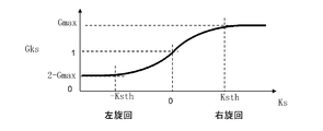
F/F操作量補正部430は、道路曲率Ksの正負に基づき左旋回であるか右旋回であるかを判別し、フィードフォワードF/F操作量FYFFを逸脱リスクCORL,CORRに基づき下記のようにして補正する。
・Ks<0のとき(左旋回時)
FY*FF=m・Ks・Vc2・(1-CORL)
・Ks>0のとき(右旋回時)
FY*FF=m・Ks・Vc2・(1-CORR) Therefore, the F / F operationamount correction unit 430 and the F / B operation amount correction unit 440 deviating from the feedforward F / F operation amount FY FF and the feedback F / B operation amount FY FB as follows. Correct according to L and COR R.
The F / F operationamount correction unit 430 determines whether it is a left turn or a right turn based on whether the road curvature Ks is positive or negative, and sets the feedforward F / F operation amount FY FF to the departure risk COR L , COR R Correct based on the following.
・ When Ks <0 (when turning left)
FY * FF = m · Ks · Vc 2 · (1-COR L )
・ When Ks> 0 (when turning right)
FY * FF = m · Ks · Vc 2 · (1-COR R )
F/F操作量補正部430は、道路曲率Ksの正負に基づき左旋回であるか右旋回であるかを判別し、フィードフォワードF/F操作量FYFFを逸脱リスクCORL,CORRに基づき下記のようにして補正する。
・Ks<0のとき(左旋回時)
FY*FF=m・Ks・Vc2・(1-CORL)
・Ks>0のとき(右旋回時)
FY*FF=m・Ks・Vc2・(1-CORR) Therefore, the F / F operation
The F / F operation
・ When Ks <0 (when turning left)
FY * FF = m · Ks · Vc 2 · (1-COR L )
・ When Ks> 0 (when turning right)
FY * FF = m · Ks · Vc 2 · (1-COR R )
つまり、F/F操作量補正部430は、例えば自車両が右カーブを走行するときに、旋回内側である右側への逸脱リスクが高くなるほど、フィードフォワードF/F操作量FYFFをより小さく補正し、自車両を旋回内側である右側へ移動させる横力を減じる。
これにより、フィードフォワードF/F操作量FYFFが悪影響を及ぼして、自車両が旋回内側に逸脱することを抑制できる。 That, F / F operationamount compensation unit 430, for example, when the vehicle is traveling a right curve, the more deviation risk to a turning inner right increases, smaller corrected feedforward F / F operation amount FY FF Reduce the lateral force that causes the vehicle to move to the right, which is the inside of a turn.
Thus, feedforward F / F operation amount FY FF is an adverse effect, it can be suppressed where the vehicle deviates turning inward.
これにより、フィードフォワードF/F操作量FYFFが悪影響を及ぼして、自車両が旋回内側に逸脱することを抑制できる。 That, F / F operation
Thus, feedforward F / F operation amount FY FF is an adverse effect, it can be suppressed where the vehicle deviates turning inward.
また、F/B操作量補正部440は、目標点座標(Xp,Yp)と前方注視点(Xs,Ys)との距離GFBの正負に基づき、自車両が目標点座標(Xp,Yp)よりも右側を走行しているか左側を走行しているかを判別し、フィードバックF/B操作量FYFBを逸脱リスクCORL,CORRに基づき下記のように補正する。
・GFB<0のとき(換言すれば、目標点座標(Xp,Yp)よりも右側を走行中)
FY*FB=PID(GFB)・(1-CORL)
・GFB>0のとき(換言すれば、目標点座標(Xp,Yp)よりも左側を走行中)
FY*FB=PID(GFB)・(1-CORR) Further, F / B operationamount correction unit 440 sets the target point coordinates (Xp, Yp) based on whether the distance G FB between the target point coordinates (Xp, Yp) and the forward fixation point (Xs, Ys) is positive or negative. It is determined whether the vehicle is traveling on the right side or on the left side, and the feedback F / B manipulated variable FYFB is corrected as follows based on the departure risks COR L and COR R.
· When G FB <0 (in other words, traveling to the right of the target point coordinates (Xp, Yp))
FY * FB = PID (G FB ) (1-COR L )
· When G FB > 0 (in other words, traveling to the left of the target point coordinates (Xp, Yp))
FY * FB = PID (G FB ) (1-COR R )
・GFB<0のとき(換言すれば、目標点座標(Xp,Yp)よりも右側を走行中)
FY*FB=PID(GFB)・(1-CORL)
・GFB>0のとき(換言すれば、目標点座標(Xp,Yp)よりも左側を走行中)
FY*FB=PID(GFB)・(1-CORR) Further, F / B operation
· When G FB <0 (in other words, traveling to the right of the target point coordinates (Xp, Yp))
FY * FB = PID (G FB ) (1-COR L )
· When G FB > 0 (in other words, traveling to the left of the target point coordinates (Xp, Yp))
FY * FB = PID (G FB ) (1-COR R )
つまり、F/B操作量補正部440は、例えば自車両が目標点座標(Xp,Yp)よりも右側を走行中であって、フィードバックF/B操作量FYFBが左側へ自車両を移動させる力を要求する場合、左路端逸脱リスクCORLが高いほど車両を目標点座標(Xp,Yp)に向けて移動させる横力を減じる。
これにより、フィードバックF/B操作量FYFBが生じさせる横力によって車両が車線から逸脱することを抑制できる。 That, F / B operationamount compensation unit 440, a traveling to the right, move the vehicle feedback F / B operation amount FY FB is to the left than for example the vehicle is the target point coordinates (Xp, Yp) When a force is required, the higher the left road edge departure risk COR L , the lower the lateral force for moving the vehicle toward the target point coordinates (Xp, Yp).
Thus, the vehicle can be prevented from departing from the lane by the lateral force feedback F / B operation amount FY FB gives rise.
これにより、フィードバックF/B操作量FYFBが生じさせる横力によって車両が車線から逸脱することを抑制できる。 That, F / B operation
Thus, the vehicle can be prevented from departing from the lane by the lateral force feedback F / B operation amount FY FB gives rise.
また、ヨーモーメント補正部460は、車両挙動安定化ヨーモーメントMstを逸脱リスクCORL,CORRに応じて補正する機能を有する。
例えば、自車両の路端右側への逸脱リスクが高い場合であって、自車両が左向きにスピンする傾向にあり、安定化のために右旋回促進モーメントが要求される場合を想定する。
この場合、上記のようにして操舵角度δが決定されると、右操舵、つまり、カウンターステアが発生し、自車両の車線からの逸脱を助長する懸念がある。 Further, the yawmoment correction unit 460 has a function of correcting the vehicle behavior stabilization yaw moment Mst in accordance with the departure risks COR L and COR R.
For example, it is assumed that there is a high risk of departure of the host vehicle to the right of the roadside, the host vehicle tends to spin left, and a right turn acceleration moment is required for stabilization.
In this case, when the steering angle δ is determined as described above, there is a concern that right steering, that is, counter-steer occurs, which promotes the departure of the host vehicle from the lane.
例えば、自車両の路端右側への逸脱リスクが高い場合であって、自車両が左向きにスピンする傾向にあり、安定化のために右旋回促進モーメントが要求される場合を想定する。
この場合、上記のようにして操舵角度δが決定されると、右操舵、つまり、カウンターステアが発生し、自車両の車線からの逸脱を助長する懸念がある。 Further, the yaw
For example, it is assumed that there is a high risk of departure of the host vehicle to the right of the roadside, the host vehicle tends to spin left, and a right turn acceleration moment is required for stabilization.
In this case, when the steering angle δ is determined as described above, there is a concern that right steering, that is, counter-steer occurs, which promotes the departure of the host vehicle from the lane.
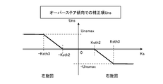
そこで、ヨーモーメント補正部460は、以下のように、車両挙動安定化ヨーモーメントMstを逸脱リスクCORL,CORRに応じて修正する。
・Mst<0のとき(左旋回促進)
M*st=Mst・(1-CORL)
・Mst>0のとき(右旋回促進)
M*st=Mst・(1-CORR)
つまり、例えば右旋回を促進させる車両挙動安定化ヨーモーメントMstが要求されるときに、自車両が右路端から逸脱するリスクが高いと、車両挙動安定化ヨーモーメントMstをより小さく補正して右旋回の促進を抑制し、右路端からの逸脱を抑止する。 Therefore, the yawmoment correction unit 460 corrects the vehicle behavior stabilization yaw moment Mst according to the departure risks COR L and COR R as follows.
・ When Mst <0 (left turn promotion)
M * st = Mst (1-COR L )
・ When Mst> 0 (right turn promotion)
M * st = Mst (1-COR R )
That is, for example, when the vehicle behavior stabilization yaw moment Mst for promoting a right turn is required, if the risk of the host vehicle deviating from the right road edge is high, the vehicle behavior stabilization yaw moment Mst is corrected smaller. The promotion of the right turn is suppressed, and the departure from the right road end is suppressed.
・Mst<0のとき(左旋回促進)
M*st=Mst・(1-CORL)
・Mst>0のとき(右旋回促進)
M*st=Mst・(1-CORR)
つまり、例えば右旋回を促進させる車両挙動安定化ヨーモーメントMstが要求されるときに、自車両が右路端から逸脱するリスクが高いと、車両挙動安定化ヨーモーメントMstをより小さく補正して右旋回の促進を抑制し、右路端からの逸脱を抑止する。 Therefore, the yaw
・ When Mst <0 (left turn promotion)
M * st = Mst (1-COR L )
・ When Mst> 0 (right turn promotion)
M * st = Mst (1-COR R )
That is, for example, when the vehicle behavior stabilization yaw moment Mst for promoting a right turn is required, if the risk of the host vehicle deviating from the right road edge is high, the vehicle behavior stabilization yaw moment Mst is corrected smaller. The promotion of the right turn is suppressed, and the departure from the right road end is suppressed.
目標操舵量演算部450は、上記のようにして逸脱リスクに応じて補正された値FY*FF、FY*FB、M*stを用いて舵角操作量δを算出することで、逸脱リスクが高い場合は路端から離れる操舵が優先され、路端から離れると通常通りに車両挙動安定化要求値が適切に処理され、逸脱リスクが高い場合と逸脱リスクが低い場合との間もシームレスに制御することができる。
また、ブレーキモーメント演算部470も、上記のようにして逸脱リスクに応じて補正された値FY*FF、FY*FB、M*stを用いてブレーキモーメントMBを演算することで、逸脱リスクを加味しつつ、目標走行軌跡への追従性と車両挙動安定化を両立させることができる。 The target steeringamount calculation unit 450 calculates the steering angle operation amount δ using the values FY * FF , FY * FB , and M * st corrected according to the departure risk as described above, whereby the departure risk is obtained. When high, the steering away from the roadside is prioritized, and when moving away from the roadside, the vehicle behavior stabilization requirement value is properly processed as usual, and seamless control is performed between high departure risk and low departure risk. can do.
The brakemoment calculation unit 470 also, by calculating the braking torque M B using the corrected value depending on departure risk as described above FY * FF, FY * FB, the M * st, deviations risk It is possible to achieve both the followability to the target travel locus and the stabilization of the vehicle behavior while considering it.
また、ブレーキモーメント演算部470も、上記のようにして逸脱リスクに応じて補正された値FY*FF、FY*FB、M*stを用いてブレーキモーメントMBを演算することで、逸脱リスクを加味しつつ、目標走行軌跡への追従性と車両挙動安定化を両立させることができる。 The target steering
The brake
図9は、自律運転中に、行動戦略コントローラ14及び運動戦略コントローラ15の機能によって、車両の挙動安定化要求と逸脱リスクとに応じて目標操舵量が補正される様子を例示する。
例えば、自車両がA位置であるとき、前方注視点(Xs,Ys)は目標点座標(Xp,Yp)の左側であるため、フィードバックF/B操作量FYFBは右旋回力を発生させる値に設定される。
しかし、前方のカーブが左カーブであることからフィードフォワードF/F操作量FYFFは左旋回力を発生させる値に設定され、かつ、フィードフォワードF/F操作量FYFFがフィードバックF/B操作量FYFBよりも大きく、フィードフォワードF/F操作量FYFFに基づいて左旋回力を発生させることで自車両が左路端から逸脱する可能性がある。 FIG. 9 illustrates the manner in which the target steering amount is corrected according to the behavior stabilization request of the vehicle and the deviation risk by the functions of thebehavior strategy controller 14 and the movement strategy controller 15 during autonomous driving.
For example, when the host vehicle is A position, the forward fixed point (Xs, Ys) Since it is left of the target point coordinates (Xp, Yp), the feedback F / B operation amount FY FB generates a right swirling force value Set to
However, feedforward F / F operation amount since the curve ahead is the left curve FY FF is set to a value that generates a left turning force, and feedforward F / F operation amount FY FF feedback F / B operation amount larger than FY FB, the vehicle by generating a left turning force based on the feedforward F / F operation amount FY FF is likely to deviate from the left channel end.
例えば、自車両がA位置であるとき、前方注視点(Xs,Ys)は目標点座標(Xp,Yp)の左側であるため、フィードバックF/B操作量FYFBは右旋回力を発生させる値に設定される。
しかし、前方のカーブが左カーブであることからフィードフォワードF/F操作量FYFFは左旋回力を発生させる値に設定され、かつ、フィードフォワードF/F操作量FYFFがフィードバックF/B操作量FYFBよりも大きく、フィードフォワードF/F操作量FYFFに基づいて左旋回力を発生させることで自車両が左路端から逸脱する可能性がある。 FIG. 9 illustrates the manner in which the target steering amount is corrected according to the behavior stabilization request of the vehicle and the deviation risk by the functions of the
For example, when the host vehicle is A position, the forward fixed point (Xs, Ys) Since it is left of the target point coordinates (Xp, Yp), the feedback F / B operation amount FY FB generates a right swirling force value Set to
However, feedforward F / F operation amount since the curve ahead is the left curve FY FF is set to a value that generates a left turning force, and feedforward F / F operation amount FY FF feedback F / B operation amount larger than FY FB, the vehicle by generating a left turning force based on the feedforward F / F operation amount FY FF is likely to deviate from the left channel end.
ここで、前方注視点(Xs,Ys)は、旋回内側である道路左端に近く、左路端逸脱リスクCORLが零よりも高い値(図9ではCORL=0.7)に設定され、右路端逸脱リスクCORRが零に設定される。
一方、目標点座標(Xp,Yp)よりも左側を走行中であるから、フィードバックF/B操作量FYFBは、FY*FB=PID(GFB)・(1-CORR)=PID(GFB)・(1-0)にしたがって算出され、フィードバックF/B操作量FYFBによる右旋回力の要求は、逸脱リスクによって実質的に補正されない。 Here, the forward fixation point (Xs, Ys) is set to a value close to the left end of the road, which is the inside of a turn, and the left roadside departure risk COR L is higher than zero (COR L = 0.7 in FIG. 9). End deviation risk COR R is set to zero.
On the other hand, the feedback F / B manipulated variable FYFB is FY * FB = PID (G FB ) · (1-COR R ) = PID (G) since the target point coordinates (Xp, Yp) are traveling on the left side. calculated according FB) · (1-0), in the rightward turning force by feedback F / B operation amount FY FB request is not substantially corrected by departing risk.
また、前方が左カーブであるため、フィードフォワードF/F操作量FYFFは、FY*FF=m・Ks・Vc2・(1-CORL)にしたがって算出されるため、フィードフォワードF/F操作量FYFFによる左旋回力の要求は逸脱リスクによって減少補正されることになる。
つまり、フィードバックF/B操作量FYFBによる右旋回力の要求は、逸脱リスクによって補正されないのに対し、フィードフォワードF/F操作量FYFFによる左旋回力の要求は逸脱リスクによって減少補正されるので、相対的に右旋回力の要求が増えて右側への操舵が実施され、道路左端への逸脱が抑制される。 Also, since the front is a left curve, the feedforward F / F manipulated variable FY FF is calculated according to FY * FF = m Ks Vc 2 (1-COR L ), so the feedforward F / F The requirement of the left turning force by the manipulated variable FY FF is reduced and corrected by the deviation risk.
That is, the request for the right turning force by the feedback F / B manipulated variable FY FB is not corrected by the departure risk, while the request of the left turning force by the feed forward F / F manipulated variable FY FF is corrected by the departure risk. Relatively, the demand for the right turning force is increased and steering to the right is performed, and deviation to the left end of the road is suppressed.
このように、運動戦略コントローラ15が逸脱リスクCORL、CORRによる補正を実施しない場合、フィードフォワードF/F操作量FYFFがフィードバックF/B操作量FYFBと逆方向であってかつフィードバックF/B操作量FYFBよりも大きいために、フィードフォワードF/F操作量FYFFによって車線から逸脱する可能性がある。
これに対し、運動戦略コントローラ15が逸脱リスクCORL、CORRによる補正を実施すると、逸脱リスクCORL、CORRに応じてフィードフォワードF/F操作量FYFFが小さく補正されることで、車線逸脱が抑制される。 Thus, deviations exercisestrategy controller 15 risk COR L, COR when R choose not to implement the correction, and a feedforward F / F operation amount FY FF is feedback F / B operation amount FY FB and reverse feedback F / for greater than B operation amount FY FB, it can deviate from the lane by the feed-forward F / F operation amount FY FF.
In contrast, when themotion strategy controller 15 deviates risk COR L, carrying out the correction by COR R, by departing risk COR L, feedforward F / F operation amount FY FF in accordance with the COR R is small correction, lane Deviation is suppressed.
これに対し、運動戦略コントローラ15が逸脱リスクCORL、CORRによる補正を実施すると、逸脱リスクCORL、CORRに応じてフィードフォワードF/F操作量FYFFが小さく補正されることで、車線逸脱が抑制される。 Thus, deviations exercise
In contrast, when the
次に、自車両がB位置で自車両が左向きにスピンする傾向であり、かつ、前方のカーブが右カーブであるときの目標操舵量の補正を説明する。
この場合、前方注視点(Xs,Ys)は目標点座標(Xp,Yp)の右側であるため、フィードバックF/B操作量FYFBは左旋回力を発生させる値に設定されが、前方のカーブが右カーブであることからフィードフォワードF/F操作量FYFFは右旋回力を発生させる値に設定され、更に、車両の挙動安定化に必要なモーメントMstも右旋回を発生させる値に設定される。 Next, correction of the target steering amount when the subject vehicle tends to spin leftward at position B and the front curve is the right curve will be described.
In this case, forward fixed point (Xs, Ys) Since it is right of the target point coordinates (Xp, Yp), the feedback F / B operation amount FY FB is set to a value that generates a left turning force, the front curve feedforward F / F operation amount FY FF from being a right curve is set to a value that generates a right swirling force, further, the moment Mst required behavior stability of the vehicle is set to a value that generates a right turn Ru.
そして、フィードバックF/B操作量FYFBと逆向きのフィードフォワードF/F操作量FYFFと、同じくフィードバックF/B操作量FYFBと逆向きの車両挙動安定化ヨーモーメントMstとの合計が、フィードバックF/B操作量FYFBよりも大きく、フィードフォワードF/F操作量FYFFと車両挙動安定化ヨーモーメントMstとによる右旋回力によって自車両が右路端から逸脱する可能性がある。
なお、車両挙動安定化ヨーモーメントMstは、車両安定化モーメント操作量である。
ここで、前方注視点(Xs,Ys)が道路右端に近いことから右路端逸脱リスクCORRが零よりも高い値(図9ではCORR=0.9)に設定され、左路端逸脱リスクCORLが零に設定される。 The sum of the feedback F / B operation amount FY FB in the opposite direction from the feed-forward F / F operation amount FY FF and, also a feedback F / B operation amount FY FB in the opposite direction from the vehicle behavior stabilization yaw moment Mst is, larger than the feedback F / B operation amount FY FB, there is a possibility that the vehicle will deviate from the right path end by the right swirling force by the feed-and-forward F / F operation amount FY FF and vehicle stability yaw moment Mst.
The vehicle behavior stabilization yaw moment Mst is a vehicle stabilization moment operation amount.
Here, since the forward fixation point (Xs, Ys) is close to the right end of the road, the right roadside departure risk COR R is set to a value higher than zero (COR R = 0.9 in FIG. 9). L is set to zero.
一方、目標点座標(Xp,Yp)よりも右側を走行中であるから、フィードバックF/B操作量FYFBは、FY*FB=PID(GFB)・(1-CORL)=PID(GFB)・(1-0)にしたがって算出されるため、フィードバックF/B操作量FYFBによる左旋回力の要求は、逸脱リスクによって実質的に補正されない。
また、前方が右カーブであり、フィードフォワードF/F操作量FYFFは、FY*FF=m・Ks・Vc2・(1-CORR)にしたがって算出されるため、フィードフォワードF/F操作量FYFFによる右旋回力の要求は逸脱リスクによって減少補正されることになる。 On the other hand, the target point coordinates (Xp, Yp) than do the vehicle is traveling on the right, feedback F / B operation amount FY FB is, FY * FB = PID (G FB) · (1-COR L) = PID (G Since it is calculated according to FB ) · (1-0), the requirement of the left turning force by the feedback F / B manipulated variable FY FB is not substantially corrected by the departure risk.
In addition, since the front is a right curve, and the feedforward F / F manipulated variable FY FF is calculated according to FY * FF = m Ks Vc 2 (1-COR R ), the feedforward F / F operation The demand for right-turning force by means of the quantity FY FF will be reduced and corrected by the risk of departure.
更に、車両挙動安定化ヨーモーメントMstは、Mst>0であるから、M*st=Mst・(1-CORR)にしたがって算出され、車両挙動安定化ヨーモーメントMstによる右旋回力の要求も逸脱リスクによって減少補正されることになる。
つまり、フィードバックF/B操作量FYFBによる左旋回力の要求は、逸脱リスクによって補正されないのに対し、フィードフォワードF/F操作量FYFF及び車両挙動安定化ヨーモーメントMstによる右旋回力の要求は逸脱リスクによって減少補正されるので、相対的に左旋回力の要求が増えて左側への操舵が実施され、自車両の道路右端への逸脱が抑制される。 Furthermore, since the vehicle behavior stabilization yaw moment Mst is Mst> 0, it is calculated according to M * st = Mst · (1−COR R ), and the demand for the right turn force due to the vehicle behavior stabilization yaw moment Mst also deviates The risk will be reduced and corrected.
That is, while the demand for the left turning force by the feedback F / B manipulated variable FY FB is not corrected by the departure risk, the demand for the right turning force by the feedforward F / F manipulated variable FY FF and the vehicle behavior stabilization yaw moment Mst is Since the reduction risk is corrected by the departure risk, the demand for the left turning force is relatively increased and steering to the left is performed, and the departure of the vehicle to the right end of the road is suppressed.
このように、フィードバックF/B操作量FYFBと逆向きのフィードフォワードF/F操作量FYFFと、同じくフィードバックF/B操作量FYFBと逆向きの車両挙動安定化ヨーモーメントMstとの合計が、フィードバックF/B操作量FYFBよりも大きいときに、運動戦略コントローラ15は、逸脱リスクに応じて車両挙動安定化ヨーモーメントMst及びフィードフォワードF/F操作量FYFFが小さくなるように補正し、車両挙動安定化ヨーモーメントMstが大きいことによる車線逸脱を抑制する。
Total Thus, the feedback F / B operation amount FY FB in the opposite direction from the feed-forward F / F operation amount FY FF, the same feedback F / B operation amount FY FB in the opposite direction from the vehicle behavior stabilization yaw moment Mst Is larger than the feedback F / B manipulated variable FY FB , the motion strategy controller 15 corrects the vehicle behavior stabilization yaw moment Mst and the feedforward F / F manipulated variable FY FF to become smaller according to the departure risk. And suppress lane departure due to the vehicle behavior stabilization yaw moment Mst being large.
また、自車両がC位置で自車両が右向きにスピンする傾向であり、かつ、前方が緩い右カーブであるときの目標操舵量の補正を説明する。
この場合、前方注視点(Xs,Ys)は目標点座標(Xp,Yp)の僅かに左側であるため、フィードバックF/B操作量FYFBは右旋回力を発生させる値に設定され、前方のカーブが右カーブであることからフィードフォワードF/F操作量FYFFも右旋回力を発生させる値に設定される。 In addition, the correction of the target steering amount when the subject vehicle tends to spin rightward at position C and the forward curve is a loose right curve will be described.
In this case, forward fixed point (Xs, Ys) Since it is slightly left of the target point coordinates (Xp, Yp), the feedback F / B operation amount FY FB is set to a value that generates a right swirling force, the front of the curve is set to a value that also the feedforward F / F operation amount FY FF to generate a right swirling force because it is right curve.
更に、車両の挙動安定化に必要なモーメントMstは、車両が右向きにスピンする傾向を抑えるために左旋回促進のために負の値に設定される。
ここで、前方注視点(Xs,Ys)は走行幅RWの中央付近で走行リスクが十分に低いため、逸脱リスクCORL,CORRはいずれも零に設定され、フィードバックF/B操作量FYFB、フィードフォワードF/F操作量FYFF、及び車両挙動安定化ヨーモーメントMstは、逸脱リスクCORL,CORRによって補正されず、車両挙動を安定化させるために僅かに左旋回力を発生させる操舵が実施される。 Furthermore, the moment Mst necessary for stabilizing the behavior of the vehicle is set to a negative value to accelerate the left turn in order to suppress the tendency of the vehicle to spin to the right.
Here, since the forward fixation point (Xs, Ys) has a sufficiently low travel risk near the center of the travel width RW, both the departure risks COR L and COR R are set to zero, and the feedback F / B manipulated variable FY FB , Feedforward F / F manipulated variable FY FF , and vehicle behavior stabilization yaw moment Mst are not corrected by departure risks COR L and COR R , and steering that generates a slight left turning force to stabilize vehicle behavior is possible. To be implemented.
次に、逸脱リスク演算部360における逸脱リスクCORL、CORRの演算処理の一態様を詳細に説明する。
図10は、逸脱リスク演算部360の機能ブロック図である。
逸脱リスク演算部360は、車両の走行環境に関する各種情報を入力し、入力した情報に基づいて、前方注視点において走行幅から自車両が逸脱するリスク分布を示すリスクマップを作成し、作成したリスクマッップを参照して、道路左端からの車両の逸脱リスクである左路端逸脱リスクCORLと、道路右端からの車両の逸脱リスクである右路端逸脱リスクCORRをそれぞれ演算する機能を有する。
詳細には、逸脱リスク演算部360は、車体速度による補正量演算部601、路面摩擦係数による補正量演算部602、曲率による補正量演算部603、挙動状態による補正量演算部604、リスクマップ演算部605、左路端への逸脱リスク演算部606、右路端への逸脱リスク演算部607を備える。 Next, an aspect of the calculation process of the deviation risks COR L and COR R in the deviationrisk calculation unit 360 will be described in detail.
FIG. 10 is a functional block diagram of the deviationrisk calculation unit 360. As shown in FIG.
The departurerisk calculation unit 360 inputs various information related to the traveling environment of the vehicle, and based on the input information, creates a risk map indicating the risk distribution that the vehicle deviates from the traveling width at the forward gaze point, and creates the risk map Referring to, the left road edge departure risk COR L , which is a vehicle departure risk from the left end of the road, and the right road edge departure risk COR R , which is a vehicle departure risk from the right end of the road, are calculated.
In detail, the departurerisk calculation unit 360 is a correction amount calculation unit 601 based on vehicle speed, a correction amount calculation unit 602 based on road surface friction coefficient, a correction amount calculation unit 603 based on curvature, a correction amount calculation unit 604 based on behavior state, risk map calculation A part 605, a deviation risk calculation part 606 to the left road end, and a deviation risk calculation part 607 to the right road end are provided.
図10は、逸脱リスク演算部360の機能ブロック図である。
逸脱リスク演算部360は、車両の走行環境に関する各種情報を入力し、入力した情報に基づいて、前方注視点において走行幅から自車両が逸脱するリスク分布を示すリスクマップを作成し、作成したリスクマッップを参照して、道路左端からの車両の逸脱リスクである左路端逸脱リスクCORLと、道路右端からの車両の逸脱リスクである右路端逸脱リスクCORRをそれぞれ演算する機能を有する。
詳細には、逸脱リスク演算部360は、車体速度による補正量演算部601、路面摩擦係数による補正量演算部602、曲率による補正量演算部603、挙動状態による補正量演算部604、リスクマップ演算部605、左路端への逸脱リスク演算部606、右路端への逸脱リスク演算部607を備える。 Next, an aspect of the calculation process of the deviation risks COR L and COR R in the deviation
FIG. 10 is a functional block diagram of the deviation
The departure
In detail, the departure
ここで、リスクマップ演算部605におけるリスクマップの基本的な作成方法を説明する。
リスクマップ演算部605は、自車両の走行リスクが無い場合、車両周辺の障害物(路端)からの距離が十分に離れた領域が最小リスクとなるように、例えば、以下のようにしてリスクマップを作成する。 Here, a basic method of creating a risk map in the riskmap calculation unit 605 will be described.
When there is no travel risk of the host vehicle, the riskmap calculation unit 605 performs the risk as follows, for example, so that the region at a sufficient distance from the obstacle (roadside) around the vehicle is the minimum risk. Create a map
リスクマップ演算部605は、自車両の走行リスクが無い場合、車両周辺の障害物(路端)からの距離が十分に離れた領域が最小リスクとなるように、例えば、以下のようにしてリスクマップを作成する。 Here, a basic method of creating a risk map in the risk
When there is no travel risk of the host vehicle, the risk
リスクマップ演算部605は、走行幅RWの左端から逸脱リスクが最小となる地点である最小リスク地点MRPまでの距離Lsl、及び、道路右端から最小リスク地点MRPまでの距離Lsrを以下の式にしたがって演算する。
Lsl=RW/2
Lsr=RW-Lsl
つまり、上式で演算される距離Lsl,LsrはLsl=Lsrとなり、リスクマップ演算部605は、自車両の走行リスクが無い場合、走行幅RWの中央を最小リスク地点MRPに定める。 The riskmap calculation unit 605 calculates the distance Lsl from the left end of the travel width RW to the minimum risk point MRP at which deviation risk is minimum and the distance Lsr from the right end of the road to the minimum risk point MRP according to the following formula Calculate
Lsl = RW / 2
Lsr = RW-Lsl
That is, the distances Lsl and Lsr calculated by the above equation become Lsl = Lsr, and the riskmap calculation unit 605 determines the center of the travel width RW as the minimum risk point MRP when there is no travel risk of the host vehicle.
Lsl=RW/2
Lsr=RW-Lsl
つまり、上式で演算される距離Lsl,LsrはLsl=Lsrとなり、リスクマップ演算部605は、自車両の走行リスクが無い場合、走行幅RWの中央を最小リスク地点MRPに定める。 The risk
Lsl = RW / 2
Lsr = RW-Lsl
That is, the distances Lsl and Lsr calculated by the above equation become Lsl = Lsr, and the risk
次に、リスクマップ演算部605は、距離Lsl,Lsrで特定される最小リスク地点MRPから左右の路端に近づくにしたがって、逸脱リスクが指数関数的に増大するようにリスク分布(図3参照)を作成する。
ここで、基準とする道路左端からの距離をu(0≦u≦RW)で表し、リスクを指数関数的に増大させる領域の割合を定める値をa(0<a<1.0)としたときに、リスクマップ演算部605は、逸脱リスクの最大値が1.0となるように正規化するリスクマップにおける逸脱リスクの値を、図3に示す4つの領域毎に距離uの関数として以下のようにして求める。 Next, the riskmap calculation unit 605 performs risk distribution such that the departure risk increases exponentially as the left and right road edges are approached from the minimum risk point MRP specified by the distances Lsl and Lsr (see FIG. 3). Create
Here, the distance from the left end of the road as a reference is represented by u (0 ≦ u ≦ RW), and a value defining the ratio of the area in which the risk is exponentially increased is a (0 <a <1.0). The riskmap calculation unit 605 normalizes the risk map so that the maximum risk of deviation is 1.0, and the value of the risk of deviation in the risk map is calculated as a function of the distance u for each of the four regions shown in FIG. Ask.
ここで、基準とする道路左端からの距離をu(0≦u≦RW)で表し、リスクを指数関数的に増大させる領域の割合を定める値をa(0<a<1.0)としたときに、リスクマップ演算部605は、逸脱リスクの最大値が1.0となるように正規化するリスクマップにおける逸脱リスクの値を、図3に示す4つの領域毎に距離uの関数として以下のようにして求める。 Next, the risk
Here, the distance from the left end of the road as a reference is represented by u (0 ≦ u ≦ RW), and a value defining the ratio of the area in which the risk is exponentially increased is a (0 <a <1.0). The risk
リスクマップ演算部605は、0≦u≦a・Lslの領域、つまり、道路左端に近い長さがa・Lslの領域での逸脱リスクを数8の指数関数にしたがって求める。

The risk map calculation unit 605 obtains the departure risk in the area of 0 ≦ u ≦ a · Lsl, that is, the area near the left end of the road is a · Lsl according to an exponential function of Formula 8.
また、リスクマップ演算部605は、a・Lsl<u<Lslの領域、つまり、道路左端から最小リスク地点MRPまでの領域のうち、最小リスク地点MRP寄りの長さが(1-a)・Lslの領域での逸脱リスクを零とする。
同様に、リスクマップ演算部605は、Lsl<u≦Lsl+(1-a)・Lsrの領域、つまり、最小リスク地点MRPから道路右端まで領域のうち、最小リスク地点MRP寄りの長さが(1-a)・Lsrの領域での逸脱リスクを零とする。 Further, the riskmap calculation unit 605 determines that the length closer to the minimum risk point MRP is (1-a) · Lsl in the area of a · Lsl <u <Lsl, that is, the area from the left end of the road to the minimum risk point MRP The risk of deviation in the area of
Similarly, in the region of Lsl <u ≦ Lsl + (1−a) · Lsr, that is, in the region from the minimum risk point MRP to the right end of the road, the risk map calculation unit 605 -A) · The departure risk in the region of Lsr is zero.
同様に、リスクマップ演算部605は、Lsl<u≦Lsl+(1-a)・Lsrの領域、つまり、最小リスク地点MRPから道路右端まで領域のうち、最小リスク地点MRP寄りの長さが(1-a)・Lsrの領域での逸脱リスクを零とする。 Further, the risk
Similarly, in the region of Lsl <u ≦ Lsl + (1−a) · Lsr, that is, in the region from the minimum risk point MRP to the right end of the road, the risk map calculation unit 605 -A) · The departure risk in the region of Lsr is zero.
更に、リスクマップ演算部605は、Lsl+(1-a)・Lsr<u≦RWまでの領域、つまり、道路右端に近い長さがa・Lsrの領域での逸脱リスクを数9の指数関数にしたがって求める。

Furthermore, the risk map calculation unit 605 sets the departure risk in the area of Lsl + (1−a) · Lsr <u ≦ RW, that is, the area near the right end of the road to the exponential function of Equation 9. Therefore I ask for it.
自車両の走行リスクが無い場合、リスクマップ演算部605は、距離Lslと距離Lsrとを同じに設定して最小リスク地点MRPを走行幅RWの中央に定めるので、上記の距離uの関数として求められる逸脱リスクは、図3に示すような分布になる。
つまり、リスクマップ演算部605は、走行幅RWの中央、換言すれば、最小リスク地点MRPから道路左端に向けて距離(1-a)・Lsl内の領域、及び、走行幅RWの中央(最小リスク地点MRP)から道路右端に向けて距離(1-a)・Lsr内の領域、換言すれば、最小リスク地点MRPを含む走行幅RW中央の部分領域について、逸脱リスクを零に設定する。 When there is no travel risk of the host vehicle, the riskmap calculation unit 605 sets the distance Lsl and the distance Lsr to be the same and determines the minimum risk point MRP at the center of the travel width RW. The deviation risk to be obtained is distributed as shown in FIG.
That is, the riskmap calculation unit 605 calculates the center of the travel width RW, in other words, the region within the distance (1-a) Lsl from the minimum risk point MRP toward the left end of the road, and the center of the travel width RW (minimum The departure risk is set to zero for the region within the distance (1-a) · Lsr from the risk point MRP) toward the right end of the road, in other words, the central region of the travel width RW including the minimum risk point MRP.
つまり、リスクマップ演算部605は、走行幅RWの中央、換言すれば、最小リスク地点MRPから道路左端に向けて距離(1-a)・Lsl内の領域、及び、走行幅RWの中央(最小リスク地点MRP)から道路右端に向けて距離(1-a)・Lsr内の領域、換言すれば、最小リスク地点MRPを含む走行幅RW中央の部分領域について、逸脱リスクを零に設定する。 When there is no travel risk of the host vehicle, the risk
That is, the risk
そして、リスクマップ演算部605は、走行幅RWの中央から道路左端に向けて距離(1-a)・Lsl以上に離れた領域では、中央から離れるほど逸脱リスクを指数関数的に徐々に増加させ、道路左端で逸脱リスクを1.0に設定する。
同様に、リスクマップ演算部605は、走行幅RWの中央から道路右端に向けて距離(1-a)・Lsr以上に離れた領域では、中央から離れるほど逸脱リスクを指数関数的に徐々に増加させ、道路右端で逸脱リスクを1.0に設定する。 Then, the riskmap calculation unit 605 causes the departure risk to be gradually and exponentially increased as the distance from the center increases in a region away from the center of the travel width RW toward the left end of the road by a distance (1-a) · Lsl or more. Set the departure risk to 1.0 at the left end of the road.
Similarly, the riskmap calculation unit 605 increases the departure risk exponentially gradually in the area away from the center from the center of the travel width RW toward the right end of the road by a distance (1-a) · Lsr or more And set the departure risk to 1.0 at the right end of the road.
同様に、リスクマップ演算部605は、走行幅RWの中央から道路右端に向けて距離(1-a)・Lsr以上に離れた領域では、中央から離れるほど逸脱リスクを指数関数的に徐々に増加させ、道路右端で逸脱リスクを1.0に設定する。 Then, the risk
Similarly, the risk
つまり、走行リスクが無い場合、距離Lsl,Lsrは同じ距離に設定されるから、リスクマップは、図3に示すように、走行幅RWの中央を境に左右対称のリスク分布になる。
そして、逸脱リスク演算部360は、係る左右対称のリスク分布に基づき、左路端逸脱リスクCORL及び右路端逸脱リスクCORRを演算することができるが、更に、逸脱リスク演算部360は、自車両がカーブを走行する場合、自車両のコントロール性が低下するリスクを加味して、図3に示すような左右対称のリスク分布から、道路右端或いは道路左端が他方に比べてリスクが高くなるように変更することで、車線逸脱抑止と車両挙動安定化とをより高精度でかつ安定的に両立させる。 That is, when there is no travel risk, the distances Lsl and Lsr are set to the same distance, so that the risk map has a symmetrical risk distribution with respect to the center of the travel width RW as shown in FIG.
Then, the departurerisk calculation unit 360 can calculate the left road end deviation risk COR L and the right road end deviation risk COR R based on the symmetrical risk distribution, but the deviation risk calculation unit 360 further calculates When the host vehicle travels a curve, the risk of the right end of the road or the left end of the road is higher than that of the other from the symmetrical risk distribution as shown in FIG. 3 in consideration of the risk that the controllability of the host vehicle decreases. By making such changes, it is possible to achieve both lane departure suppression and vehicle behavior stabilization with higher accuracy and stability.
そして、逸脱リスク演算部360は、係る左右対称のリスク分布に基づき、左路端逸脱リスクCORL及び右路端逸脱リスクCORRを演算することができるが、更に、逸脱リスク演算部360は、自車両がカーブを走行する場合、自車両のコントロール性が低下するリスクを加味して、図3に示すような左右対称のリスク分布から、道路右端或いは道路左端が他方に比べてリスクが高くなるように変更することで、車線逸脱抑止と車両挙動安定化とをより高精度でかつ安定的に両立させる。 That is, when there is no travel risk, the distances Lsl and Lsr are set to the same distance, so that the risk map has a symmetrical risk distribution with respect to the center of the travel width RW as shown in FIG.
Then, the departure
以下では、自車両がカーブを走行するときの逸脱リスク演算部360によるリスクマップの変更処理を説明する。
逸脱リスク演算部360は、自車両がカーブを走行するときに、走行車速Vc、路面の摩擦係数μ、及び、道路曲率Ksに基づきリスクマップを変更する機能を有する。
車両がカーブを走行する場合、道路曲率Ksが大きいほど、走行車速Vcが高いほど、更に、路面の摩擦係数μが低いほど、前方のカーブを曲がりきれずにカーブの外側に膨らみ、カーブの外側に逸脱し易くなるので、逸脱リスク演算部360は、係る傾向をリスクマップに反映させる。 Below, the change process of the risk map by the deviationrisk calculating part 360 when the own vehicle drive | works a curve is demonstrated.
The departurerisk calculation unit 360 has a function of changing the risk map based on the traveling vehicle speed Vc, the friction coefficient μ of the road surface, and the road curvature Ks when the host vehicle travels a curve.
When the vehicle travels on a curve, the larger the road curvature Ks, the higher the traveling vehicle speed Vc, and the lower the friction coefficient μ of the road surface, the curve on the front bulges out of the curve without being able to bend. Thedeviation risk calculator 360 reflects such a tendency on the risk map.
逸脱リスク演算部360は、自車両がカーブを走行するときに、走行車速Vc、路面の摩擦係数μ、及び、道路曲率Ksに基づきリスクマップを変更する機能を有する。
車両がカーブを走行する場合、道路曲率Ksが大きいほど、走行車速Vcが高いほど、更に、路面の摩擦係数μが低いほど、前方のカーブを曲がりきれずにカーブの外側に膨らみ、カーブの外側に逸脱し易くなるので、逸脱リスク演算部360は、係る傾向をリスクマップに反映させる。 Below, the change process of the risk map by the deviation
The departure
When the vehicle travels on a curve, the larger the road curvature Ks, the higher the traveling vehicle speed Vc, and the lower the friction coefficient μ of the road surface, the curve on the front bulges out of the curve without being able to bend. The
まず、車体速度による補正量演算部601は、自車両の走行車速Vcに基づき第1調整ゲインGvc(1≦Gvc<2)を演算する。
第1調整ゲインGvcは、走行車速Vcが高いほどより大きな値に設定され、例えば図11に示すように、走行車速Vcが第1設定速度Vc1以下の領域では1.0に固定され、走行車速Vcが第1設定速度Vc1よりも高くなるほど徐々により高い値に設定され、走行車速Vcが第2設定速度Vc2(Vc2>Vc1)以上の領域では最大値Gvcmax(1<Gvcmax<2)に固定される。 First, the correctionamount calculation unit 601 based on the vehicle speed calculates the first adjustment gain Gvc (1 ≦ Gvc <2) based on the traveling vehicle speed Vc of the host vehicle.
The first adjustment gain Gvc is set to a larger value as the traveling vehicle speed Vc is higher. For example, as shown in FIG. 11, the traveling vehicle speed Vc is fixed to 1.0 in a region below the first set velocity Vc1. The value is set to a gradually higher value as the speed is higher than the first set speed Vc1, and is fixed to the maximum value Gvcmax (1 <Gvcmax <2) in the region where the traveling vehicle speed Vc is the second set speed Vc2 (Vc2> Vc1) or more.
第1調整ゲインGvcは、走行車速Vcが高いほどより大きな値に設定され、例えば図11に示すように、走行車速Vcが第1設定速度Vc1以下の領域では1.0に固定され、走行車速Vcが第1設定速度Vc1よりも高くなるほど徐々により高い値に設定され、走行車速Vcが第2設定速度Vc2(Vc2>Vc1)以上の領域では最大値Gvcmax(1<Gvcmax<2)に固定される。 First, the correction
The first adjustment gain Gvc is set to a larger value as the traveling vehicle speed Vc is higher. For example, as shown in FIG. 11, the traveling vehicle speed Vc is fixed to 1.0 in a region below the first set velocity Vc1. The value is set to a gradually higher value as the speed is higher than the first set speed Vc1, and is fixed to the maximum value Gvcmax (1 <Gvcmax <2) in the region where the traveling vehicle speed Vc is the second set speed Vc2 (Vc2> Vc1) or more.
次に、路面摩擦係数による補正量演算部602は、車両前方における走行環境に関する情報の1つである自車両の車輪の接地路面の摩擦係数μに基づき第2調整ゲインGμ(1≦Gμ<2)を演算する。
第2調整ゲインGμは、路面の摩擦係数μが低いほど、換言すれば、路面が滑り易いほどより大きな値に設定され、例えば図12に示すように、摩擦係数μが第1設定値μ1以下の領域では最大値Gμmax(1<Gμmax<2)に固定され、摩擦係数μが第1設定値μ1よりも高くなるほど徐々により低い値に設定され、摩擦係数μが第2設定値μ2(μ2>μ1)以上の領域では1.0に固定される。 Next, the second adjustment gain Gμ (1 ≦ Gμ <2) based on the coefficient of friction μ of the ground surface of the wheels of the vehicle, which is one of the information on the traveling environment ahead of the vehicle. Calculate).
The second adjustment gain Gμ is set to a larger value as the friction coefficient μ of the road surface is lower, in other words, as the road surface is slippery. For example, as shown in FIG. 12, the friction coefficient μ is less than the first set value μ1. Is fixed to the maximum value Gμmax (1 <Gμmax <2), and the friction coefficient μ is set to a gradually lower value as it becomes higher than the first set value μ1, and the friction coefficient μ is set to the second set value μ2 (μ2> It is fixed to 1.0 in the region of μ1) or more.
次に、曲率による補正量演算部603は、車体速度による補正量演算部601で演算された第1調整ゲインGvcと、路面摩擦係数による補正量演算部602で演算された第2調整ゲインGμとを入力し、第1調整ゲインGvcと第2調整ゲインGμとのうちでより大きな値を選択する処理(セレクトハイ処理)を実施し、選択した値を第3調整ゲインGmaxにセットする(Gmax=max(Gvc,Gμ))。
更に、曲率による補正量演算部603は、前方注視点(Xs,Ys)における道路曲率Ksと、第3調整ゲインGmaxとに基づき第4調整ゲインGksを求める。
ここで、道路曲率Ksは、車両前方における走行環境に関する情報の1つであり、外界認識情報に基づき演算される。 Next, the correctionamount calculation unit 603 based on curvature calculates the first adjustment gain Gvc calculated by the correction amount calculation unit 601 based on vehicle speed, and the second adjustment gain Gμ calculated by the correction amount calculation unit 602 based on the road surface friction coefficient. To select a larger value among the first adjustment gain Gvc and the second adjustment gain Gμ (select high processing), and set the selected value as the third adjustment gain Gmax (Gmax = max (Gvc, Gμ)).
Furthermore, the correctionamount calculation unit 603 based on curvature determines a fourth adjustment gain Gks based on the road curvature Ks at the forward fixation point (Xs, Ys) and the third adjustment gain Gmax.
Here, the road curvature Ks is one of the information related to the traveling environment in front of the vehicle, and is calculated based on the external world recognition information.
更に、曲率による補正量演算部603は、前方注視点(Xs,Ys)における道路曲率Ksと、第3調整ゲインGmaxとに基づき第4調整ゲインGksを求める。
ここで、道路曲率Ksは、車両前方における走行環境に関する情報の1つであり、外界認識情報に基づき演算される。 Next, the correction
Furthermore, the correction
Here, the road curvature Ks is one of the information related to the traveling environment in front of the vehicle, and is calculated based on the external world recognition information.
曲率による補正量演算部603は、第3調整ゲインGmaxに基づき例えば図13に示すようなマップを構築し、係るマップを参照して第4調整ゲインGksを求める。
本実施形態では、左旋回の道路曲率Ksが負値で表され、右旋回の道路曲率Ksが正値で表される。
そのため、図13に示すマップでは、左旋回と右旋回とを道路曲率Ksの正負で区別し、曲率Ksが零の直線路であるときに第4調整ゲインGksは1.0に設定され、右旋回の道路曲率Ksが大きくなるほど第4調整ゲインGksは1.0よりも大きく設定され、左旋回の道路曲率Ksが大きくなるほど第4調整ゲインGksは1.0よりも小さく設定される。 The correctionamount calculation unit 603 based on curvature constructs, for example, a map as shown in FIG. 13 based on the third adjustment gain Gmax, and obtains the fourth adjustment gain Gks with reference to the map.
In the present embodiment, the road curvature Ks of left turn is represented by a negative value, and the road curvature Ks of right turn is represented by a positive value.
Therefore, in the map shown in FIG. 13, the left turn and the right turn are distinguished by the positive and negative of the road curvature Ks, and the fourth adjustment gain Gks is set to 1.0 when the curvature Ks is a straight road of zero. The fourth adjustment gain Gks is set to be larger than 1.0 as the road curvature Ks of the turn is larger, and the fourth adjustment gain Gks is set to be smaller than 1.0 as the road curvature Ks of the left turn is larger.
本実施形態では、左旋回の道路曲率Ksが負値で表され、右旋回の道路曲率Ksが正値で表される。
そのため、図13に示すマップでは、左旋回と右旋回とを道路曲率Ksの正負で区別し、曲率Ksが零の直線路であるときに第4調整ゲインGksは1.0に設定され、右旋回の道路曲率Ksが大きくなるほど第4調整ゲインGksは1.0よりも大きく設定され、左旋回の道路曲率Ksが大きくなるほど第4調整ゲインGksは1.0よりも小さく設定される。 The correction
In the present embodiment, the road curvature Ks of left turn is represented by a negative value, and the road curvature Ks of right turn is represented by a positive value.
Therefore, in the map shown in FIG. 13, the left turn and the right turn are distinguished by the positive and negative of the road curvature Ks, and the fourth adjustment gain Gks is set to 1.0 when the curvature Ks is a straight road of zero. The fourth adjustment gain Gks is set to be larger than 1.0 as the road curvature Ks of the turn is larger, and the fourth adjustment gain Gks is set to be smaller than 1.0 as the road curvature Ks of the left turn is larger.
更に、図13に示すマップでは、道路曲率Ksが設定曲率Ksth(Ksth>0)よりも大きい右旋回のときの第4調整ゲインGksは第3調整ゲインGmaxと同じ値に設定され、道路曲率Ksが設定曲率“Ksth×-1”よりも小さい左旋回のときの第4調整ゲインGksは「2-Gmax」に設定される。
つまり、第4調整ゲインGksは、「Gmax」と「2-Gmax」とで挟まれる領域を可変範囲とし、道路曲率Ksが零であればGks=1.0に設定され、道路曲率Ksが正側に増えるほど第4調整ゲインGksは第3調整ゲインGmaxに近づき、道路曲率Ksが負側に減るほど第4調整ゲインGksは「2-Gmax」に近づく。 Furthermore, in the map shown in FIG. 13, the fourth adjustment gain Gks at the time of a right turn where the road curvature Ks is larger than the set curvature Ksth (Ksth> 0) is set to the same value as the third adjustment gain Gmax. The fourth adjustment gain Gks when the left turn where Ks is smaller than the set curvature “Ksth × −1” is set to “2-Gmax”.
That is, the fourth adjustment gain Gks sets an area between “Gmax” and “2-Gmax” as a variable range, and if the road curvature Ks is zero, Gks = 1.0 is set, and the road curvature Ks is on the positive side The fourth adjustment gain Gks approaches the third adjustment gain Gmax as it increases, and the fourth adjustment gain Gks approaches “2-Gmax” as the road curvature Ks decreases to the negative side.
ここで、第3調整ゲインGmaxは、走行車速Vcに基づく第1調整ゲインGvcと、路面の摩擦係数μに基づく第2調整ゲインGμとのうちのより大きな値である。
このため、右旋回時には、同じ道路曲率Ksであっても、走行車速Vcが高いほど、また、摩擦係数μが小さいほど、第4調整ゲインGksはより大きな値に設定され、左旋回時には、同じ道路曲率Ksであっても、走行車速Vcが高いほど、また、摩擦係数μが小さいほど、第4調整ゲインGksはより小さい値に設定されることになる。 Here, the third adjustment gain Gmax is a larger value of the first adjustment gain Gvc based on the traveling vehicle speed Vc and the second adjustment gain Gμ based on the friction coefficient μ of the road surface.
For this reason, the fourth adjustment gain Gks is set to a larger value as the traveling vehicle speed Vc is higher and as the friction coefficient μ is smaller, even when the road curvature Ks is the same, at the time of right turn. Even with the same road curvature Ks, the fourth adjustment gain Gks is set to a smaller value as the traveling vehicle speed Vc is higher and as the friction coefficient μ is smaller.
そして、リスクマップ演算部605は、道路左端から最小リスク地点MRPまでの距離Lslと道路右端から最小リスク地点MRPまでの距離Lsrを、第4調整ゲインGksを用いて以下の式にしたがって演算する。
Lsl=RW・Gks/2
Lsr=RW-Lsl Then, the riskmap calculation unit 605 calculates the distance Lsl from the left end of the road to the minimum risk point MRP and the distance Lsr from the right end of the road to the minimum risk point MRP according to the following equation using the fourth adjustment gain Gks.
Lsl = RW · Gks / 2
Lsr = RW-Lsl
Lsl=RW・Gks/2
Lsr=RW-Lsl Then, the risk
Lsl = RW · Gks / 2
Lsr = RW-Lsl
例えば、右旋回時で第4調整ゲインGksが1.0よりも大きい値に設定された場合、道路左端から最小リスク地点MRPまでの距離Lslは、走行幅RWの中央よりも右寄り、つまり、旋回内側寄りに設定され、係る距離Lsl,Lsrに基づくリスクマップは、旋回内側よりも旋回外側のリスクが大きくなるように変更されることになる。
つまり、右旋回時では、道路曲率Ksが大きいほど、走行車速Vcが高いほど、更に、路面の摩擦係数μが低いほど、最小リスク地点MRPは走行幅RWの中央からより道路右端寄り、つまり、旋回内側寄りに設定され、リスクマップは旋回内側よりも旋回外側の逸脱リスクが大きくなるように設定される。 For example, when the fourth adjustment gain Gks is set to a value larger than 1.0 when turning right, the distance Lsl from the left end of the road to the minimum risk point MRP is closer to the right than the center of the travel width RW, that is, inside the turning The risk map, which is set closer and is based on the distances Lsl and Lsr, is changed so that the risk of the turning outside is larger than that of the turning inside.
That is, when turning right, the larger the road curvature Ks, the higher the traveling vehicle speed Vc, and the lower the road surface friction coefficient μ, the closer to the right end of the road the minimum risk point MRP from the center of the traveling width RW, ie The risk map is set so that the risk of deviation outside the turning is larger than that inside the turning.
一方、左旋回時で第4調整ゲインGksが1.0よりも小さい値に設定された場合、道路左端から最小リスク地点MRPまでの距離Lslは、走行幅RWの中央よりも左寄り、つまり、旋回内側寄りに設定され、係る距離Lsl,Lsrに基づくリスクマップは、旋回内側よりも旋回外側のリスクが大きくなるように設定されることになる。
つまり、左旋回時では、道路曲率Ksが大きいほど、走行車速Vcが高いほど、更に、路面の摩擦係数μが低いほど、最小リスク地点MRPは走行幅RWの中央からより道路左端寄りに設定され、リスクマップは旋回内側よりも旋回外側の逸脱リスクが大きくなるように設定される。 On the other hand, when the fourth adjustment gain Gks is set to a value smaller than 1.0 when turning left, the distance Lsl from the left end of the road to the minimum risk point MRP is closer to the left than the center of the travel width RW, that is, closer to the inside of the turn The risk map based on the distances Lsl and Lsr is set such that the risk of the turning outside is larger than the turning inside.
That is, at the time of left turn, the minimum risk point MRP is set closer to the left end of the road from the center of the travel width RW as the road curvature Ks is larger, the traveling vehicle speed Vc is higher, and the friction coefficient μ of the road surface is lower. The risk map is set such that the risk of deviation outside the turning is larger than that inside the turning.
車両がカーブを走行する場合、道路曲率Ksが大きいほど、走行車速Vcが高いほど、更に、路面の摩擦係数μが低いほど、十分な旋回力を得られずに、車両がカーブの外側に逸脱する可能性が高くなる。
そこで、逸脱リスク演算部360は、道路曲率Ksが大きいほど、走行車速Vcが高いほど、更に、路面の摩擦係数μが低いほど、最小リスク地点MRPを走行幅RWの中央から旋回内側にずらすことで、旋回内側よりも旋回外側の逸脱リスクをより大きく設定する。 When the vehicle travels on a curve, the vehicle deviates to the outside of the curve without obtaining sufficient turning force as the road curvature Ks increases, as the traveling vehicle speed Vc increases, and as the friction coefficient μ of the road surface decreases. You are more likely to
Therefore, the departurerisk computing unit 360 shifts the minimum risk point MRP from the center of the travel width RW inward to the inside of the turn as the road curvature Ks increases, as the traveling vehicle speed Vc increases, and as the friction coefficient μ of the road surface decreases. In this case, the deviation risk on the turning outside is set larger than on the turning inside.
そこで、逸脱リスク演算部360は、道路曲率Ksが大きいほど、走行車速Vcが高いほど、更に、路面の摩擦係数μが低いほど、最小リスク地点MRPを走行幅RWの中央から旋回内側にずらすことで、旋回内側よりも旋回外側の逸脱リスクをより大きく設定する。 When the vehicle travels on a curve, the vehicle deviates to the outside of the curve without obtaining sufficient turning force as the road curvature Ks increases, as the traveling vehicle speed Vc increases, and as the friction coefficient μ of the road surface decreases. You are more likely to
Therefore, the departure
逸脱リスク演算部360は、直線走行の際には、走行幅RWの中央を最小リスク地点MRPとして、左右の車線に近づくにつれて逸脱リスクを大きくするが、旋回走行の際には、カーブの走行環境に応じて最小リスク地点MRPを走行幅RWの中央から左右にずらし、ずらした最小リスク地点MRPを基準に走行幅RWの左右に逸脱リスクを大きくする。
これにより、逸脱リスクが大きい経路を避けた自動操舵が可能になり、旋回走行において自車両のコントロール性が低下するというリスクを加味して、自車両を安全な状態に保つことを向上できる。 The departurerisk calculation unit 360 sets the center of the travel width RW as the minimum risk point MRP in straight traveling, and increases the departure risk as it approaches the left and right lanes. Accordingly, the minimum risk point MRP is shifted to the left and right from the center of the travel width RW, and the departure risk to the left and right of the travel width RW is increased based on the shifted minimum risk point MRP.
This makes it possible to perform automatic steering avoiding a route having a large departure risk, and it is possible to improve keeping the own vehicle in a safe state, taking into consideration the risk that the controllability of the own vehicle decreases in cornering.
これにより、逸脱リスクが大きい経路を避けた自動操舵が可能になり、旋回走行において自車両のコントロール性が低下するというリスクを加味して、自車両を安全な状態に保つことを向上できる。 The departure
This makes it possible to perform automatic steering avoiding a route having a large departure risk, and it is possible to improve keeping the own vehicle in a safe state, taking into consideration the risk that the controllability of the own vehicle decreases in cornering.
更に、逸脱リスク演算部360は、第4調整ゲインGksに基づき求めた距離Lsl,Lsrを、自車両の挙動状態、詳細には、アンダーステアの傾向であるか否か、及び、オーバーステアの傾向であるか否かに応じて補正する機能を有する。
車両がオーバーステアの傾向であるときとは、車両が旋回内側に向けて切れ込んでいく状態であり、係る状態では、車両が旋回内側へ逸脱する可能性がある。つまり、自車両がオーバーステアの傾向である場合、十分な旋回力が得られず、車線の内側へ逸脱してしまう可能性が大きくなる。
このため、自車両がオーバーステアの傾向であるときは、オーバーステアの傾向でないときに比べて、旋回外側の逸脱リスクを小さく修正し、旋回内側の逸脱リスクを大きく修正して、旋回内側への逸脱を抑止することが合理的である。 Further, the departurerisk calculation unit 360 determines the distances Lsl and Lsr determined based on the fourth adjustment gain Gks as the behavior state of the host vehicle, specifically, whether it is understeer tendency or oversteer tendency. It has a function to correct according to whether it exists or not.
When the vehicle is tending to oversteer, it means that the vehicle cuts inward toward the inside of the turn, and in such a state, the vehicle may deviate inside the turn. That is, when the host vehicle tends to oversteer, a sufficient turning force can not be obtained, and the possibility of departing inside the lane increases.
For this reason, when the host vehicle tends to oversteer, the deviation risk on the outside of the turning is corrected to be smaller than that not being the tendency to oversteering, and the deviation risk on the inside of turning is largely corrected. It is reasonable to deter deviations.
車両がオーバーステアの傾向であるときとは、車両が旋回内側に向けて切れ込んでいく状態であり、係る状態では、車両が旋回内側へ逸脱する可能性がある。つまり、自車両がオーバーステアの傾向である場合、十分な旋回力が得られず、車線の内側へ逸脱してしまう可能性が大きくなる。
このため、自車両がオーバーステアの傾向であるときは、オーバーステアの傾向でないときに比べて、旋回外側の逸脱リスクを小さく修正し、旋回内側の逸脱リスクを大きく修正して、旋回内側への逸脱を抑止することが合理的である。 Further, the departure
When the vehicle is tending to oversteer, it means that the vehicle cuts inward toward the inside of the turn, and in such a state, the vehicle may deviate inside the turn. That is, when the host vehicle tends to oversteer, a sufficient turning force can not be obtained, and the possibility of departing inside the lane increases.
For this reason, when the host vehicle tends to oversteer, the deviation risk on the outside of the turning is corrected to be smaller than that not being the tendency to oversteering, and the deviation risk on the inside of turning is largely corrected. It is reasonable to deter deviations.
一方、車両がアンダーステアの傾向であるときとは、車両が旋回外側に膨らんでいってしまう状態であり、係る状態では、車両が旋回外側へ逸脱する可能性がある。つまり、自車両がアンダーステアの傾向である場合、十分な旋回力が得られずに自車両が車線の外側へ逸脱してしまう可能性が大きくなる。
このため、自車両がアンダーステアの傾向であるときは、アンダーステアの傾向でないときに比べて、旋回内側の逸脱リスクを小さく修正し、旋回外側の逸脱リスクを大きく修正して、旋回外側への逸脱を抑止することが合理的である。 On the other hand, when the vehicle tends to understeer is a state in which the vehicle bulges outward, and in such a state, the vehicle may deviate outward. That is, when the host vehicle tends to understeer, there is a high possibility that the host vehicle may deviate outside the lane without sufficient turning force being obtained.
For this reason, when the host vehicle is understeered, the departure risk inside the turning is corrected to be smaller than when the understeering is not given, and the departure risk outside the turning is largely corrected, and the departure toward the turning outer is It is reasonable to deter.
そこで、挙動状態による補正量演算部604は、アンダーステア傾向及びオーバーステア傾向でのリスク設定の要求に基づきリスクマップの補正項Unsを演算し、リスクマップ演算部605は、距離Lsl,Lsrを、補正項Uns及び第4調整ゲインGksを用い下式にしたがって演算する。
Lsl=RW・(Gks/2+Uns)
Lsr=RW-Lsl
但し、上式においては、0<(Gks/2+Uns)<1.0の関係が満たされるものとする。 Therefore, the correctionamount calculation unit 604 according to the behavior state calculates the correction term Uns of the risk map based on the request for risk setting in the understeer tendency and the oversteer tendency, and the risk map calculation unit 605 corrects the distances Lsl and Lsr. Calculation is performed according to the following equation using the term Uns and the fourth adjustment gain Gks.
Lsl = RW (Gks / 2 + Uns)
Lsr = RW-Lsl
However, in the above equation, the relationship of 0 <(Gks / 2 + Uns) <1.0 is satisfied.
Lsl=RW・(Gks/2+Uns)
Lsr=RW-Lsl
但し、上式においては、0<(Gks/2+Uns)<1.0の関係が満たされるものとする。 Therefore, the correction
Lsl = RW (Gks / 2 + Uns)
Lsr = RW-Lsl
However, in the above equation, the relationship of 0 <(Gks / 2 + Uns) <1.0 is satisfied.
図14のフローチャートは、挙動状態による補正量演算部604による補正項Unsの演算手順を示す。
挙動状態による補正量演算部604は、ステップS821で、自車両の挙動状態の1つであるオーバーステアに関する入力情報に基づき、自車両がオーバーステアの傾向であるか否かを判断する。
そして、自車両がオーバーステアの傾向である場合、挙動状態による補正量演算部604は、ステップS822に進み、オーバーステア傾向に応じてリスクマップを修正するための補正項Unsを、例えば図15に示すようなマップを参照して求める。 The flowchart in FIG. 14 shows the procedure for computing the correction term Uns by the correctionamount computing unit 604 according to the behavior state.
In step S 821, the correctionamount calculation unit 604 according to the behavior state determines whether the host vehicle is in the tendency of oversteer, based on input information on oversteer that is one of the host vehicle behavior states.
Then, when the host vehicle tends to oversteer, the correctionamount calculation unit 604 according to the behavior state proceeds to step S822, and the correction term Uns for correcting the risk map according to the oversteer tendency is, for example, shown in FIG. Find it by referring to the map as shown.
挙動状態による補正量演算部604は、ステップS821で、自車両の挙動状態の1つであるオーバーステアに関する入力情報に基づき、自車両がオーバーステアの傾向であるか否かを判断する。
そして、自車両がオーバーステアの傾向である場合、挙動状態による補正量演算部604は、ステップS822に進み、オーバーステア傾向に応じてリスクマップを修正するための補正項Unsを、例えば図15に示すようなマップを参照して求める。 The flowchart in FIG. 14 shows the procedure for computing the correction term Uns by the correction
In step S 821, the correction
Then, when the host vehicle tends to oversteer, the correction
図15に示す補正項Unsのマップは、オーバーステア傾向であるときの道路曲率Ksと補正項Unsとの相関を示し、道路曲率Ksの絶対値が設定値Ksth2以下である領域、つまり、略直線路である場合では補正項Unsは零に設定され、右旋回での補正項Unsは道路曲率Ksが大きくなるほど絶対値が大きな負の値に設定され、左旋回での補正項Unsは道路曲率Ksが大きくなるほど絶対値が大きな正の値に設定され、道路曲率Ksの絶対値が設定値Ksth3以上では補正項Unsの絶対値は一定値Unsmax, -Unsmaxを保持する。
The map of the correction term Uns shown in FIG. 15 shows the correlation between the road curvature Ks and the correction term Uns when the vehicle is in the oversteer tendency, and an area where the absolute value of the road curvature Ks is less than the set value Ksth2, that is, a substantially straight line In the case of a road, the correction term Uns is set to zero, the correction term Uns for right turn is set to a negative value with a larger absolute value as the road curvature Ks becomes larger, and the correction term Uns for left turn is a road curvature The absolute value is set to a larger positive value as Ks becomes larger, and the absolute value of the correction term Uns holds constant values Unsmax and -Unsmax when the absolute value of the road curvature Ks is equal to or greater than the set value Ksth3.
例えば、左旋回のときにオーバーステアの傾向になると、補正項Unsが零よりも大きな正の値に設定される結果、距離Lslはオーバーステアの傾向ではないときよりも長く補正され、最小リスク地点MRPはより旋回外側に修正されることになる。
そして、係る最小リスク地点MRPに基づくリスクマップでは、オーバーステアの傾向でないときに比べて、旋回外側の逸脱リスクが小さく、旋回内側の逸脱リスクが大きく修正され、旋回内側への逸脱を抑止する。 For example, if oversteer tends to occur when turning left, the correction term Uns is set to a positive value larger than zero, so the distance Lsl is corrected longer than when it is not oversteer, and the minimum risk point MRP will be corrected more to the outside of the turn.
Then, in the risk map based on the minimum risk point MRP, the departure risk on the outside of the turning is smaller and the departure risk on the inside of the turning is largely corrected as compared with the time of not oversteering tendency, and the turning inward is suppressed.
一方、挙動状態による補正量演算部604は、ステップS821で、自車両がオーバーステアの傾向ではないと判断すると、ステップS823に進み、自車両の挙動状態の1つであるアンダーステアに関する入力情報に基づき、自車両がアンダーステアの傾向であるか否かを判断する。
そして、自車両がアンダーステアの傾向である場合、挙動状態による補正量演算部604は、ステップS824に進み、アンダーステア傾向に応じてリスクマップを修正するための補正項Unsを、例えば図16に示すようなマップを参照して求める。 On the other hand, when the correctionamount calculation unit 604 according to the behavior state determines that the host vehicle is not in the tendency of oversteer in step S821, the process proceeds to step S823, and based on input information related to understeer which is one of the host vehicle behavior states. , It is determined whether the host vehicle is in the tendency of understeer.
Then, if the host vehicle tends to understeer, the process proceeds to step S 824, where the correction term Uns for correcting the risk map according to the understeer tendency is shown in FIG. Search by referring to the
そして、自車両がアンダーステアの傾向である場合、挙動状態による補正量演算部604は、ステップS824に進み、アンダーステア傾向に応じてリスクマップを修正するための補正項Unsを、例えば図16に示すようなマップを参照して求める。 On the other hand, when the correction
Then, if the host vehicle tends to understeer, the process proceeds to step S 824, where the correction term Uns for correcting the risk map according to the understeer tendency is shown in FIG. Search by referring to the
図16に示す補正項Unsのマップは、アンダーステア傾向であるときの道路曲率Ksと補正項Unsとの相関を示し、道路曲率Ksの絶対値が設定値以下である領域つまり、略直線路である場合では補正項Unsは零に設定され、右旋回での補正項Unsは道路曲率Ksが大きくなるほど絶対値が大きな正の値に設定され、左旋回での補正項Unsは道路曲率Ksが大きくなるほど絶対値が大きな負の値に設定される。
The map of the correction term Uns shown in FIG. 16 shows the correlation between the road curvature Ks and the correction term Uns when the vehicle is understeered, and is an area where the absolute value of the road curvature Ks is less than the set value, that is, a substantially straight road In this case, the correction term Uns is set to zero, and the correction term Uns for turning right is set to a positive value with a larger absolute value as the road curvature Ks becomes larger, and the correction term Uns for turning left has a large road curvature Ks The absolute value is set to a large negative value.
例えば、左旋回のときにアンダーステア状態になると、補正項Unsが零よりも小さい負の値に設定される結果、距離Lslはアンダーステアの傾向ではないときよりも短く補正され、最小リスク地点MRPはより旋回内側に修正されることになる。
そして、係る最小リスク地点MRPに基づくリスクマップでは、アンダーステアの傾向でないときに比べて、旋回外側の逸脱リスクが大きく、旋回内側の逸脱リスクが小さく修正され、旋回外側への逸脱を抑止する。 For example, when the vehicle is understeered when turning left, the correction term Uns is set to a negative value smaller than zero, so that the distance Lsl is corrected shorter than when it is not a tendency to understeer, and the minimum risk point MRP is more It will be corrected inside the turning.
Then, in the risk map based on the minimum risk point MRP, the departure risk on the outside of the turn is larger and the departure risk on the inside of the turn is corrected smaller than when the understeer does not tend, and the departure to the outside of the turn is suppressed.
また、挙動状態による補正量演算部604は、ステップS823で自車両がアンダーステアの傾向ではないと判断すると、ステップS825に進み、補正項Unsを零に設定する。
つまり、自車両がオーバーステアの傾向ではなく、かつ、アンダーステアの傾向でもない場合、車両の挙動状態に基づくリスクマップの変更は不要であるので、挙動状態による補正量演算部604は、補正項Unsを零に設定する。 If it is determined in step S823 that the host vehicle is not tending to understeer in step S823, the process proceeds to step S825, and the correction term Uns is set to zero.
That is, when the host vehicle is neither oversteer nor understeer, it is not necessary to change the risk map based on the behavior state of the vehicle, so the correctionamount calculation unit 604 according to the behavior state corrects the correction term Uns. Set to zero.
つまり、自車両がオーバーステアの傾向ではなく、かつ、アンダーステアの傾向でもない場合、車両の挙動状態に基づくリスクマップの変更は不要であるので、挙動状態による補正量演算部604は、補正項Unsを零に設定する。 If it is determined in step S823 that the host vehicle is not tending to understeer in step S823, the process proceeds to step S825, and the correction term Uns is set to zero.
That is, when the host vehicle is neither oversteer nor understeer, it is not necessary to change the risk map based on the behavior state of the vehicle, so the correction
以上のようにして、曲率による補正量演算部603は、道路曲率Ks、走行車速Vc、更に、路面の摩擦係数μに応じて第4調整ゲインGksを演算し、挙動状態による補正量演算部604は、自車両の挙動状態であるアンダーステア、オーバーステアに応じて補正項Unsを演算する。
そして、リスクマップ演算部605は、第4調整ゲインGks及び補正項Unsを用いて前述のようにして距離Lsl,Lsrを演算し、0≦u≦a・Lslの領域では走行幅RWの左端に近づくにしたがって逸脱リスクを指数関数的に増加させ、Lsl+(1-a)・Lsr<u≦RWの領域では、走行幅RWの右端に近づくにしたがって逸脱リスクを指数関数的に増加させるリスク分布を設定し、リスクマップを生成する。 As described above, the correctionamount calculation unit 603 by curvature calculates the fourth adjustment gain Gks according to the road curvature Ks, the traveling vehicle speed Vc, and the friction coefficient μ of the road surface, and the correction amount calculation unit 604 by the behavior state. The correction term Uns is calculated according to understeer and oversteer which are the behavior state of the host vehicle.
Then, the riskmap calculation unit 605 calculates the distances Lsl and Lsr as described above using the fourth adjustment gain Gks and the correction term Uns, and in the region of 0 ≦ u ≦ a · Lsl, at the left end of the travel width RW. The risk distribution is increased exponentially as it approaches, and in the region of Lsl + (1−a) · Lsr <u ≦ RW, the risk distribution is exponentially increased as the right end of the travel width RW is approached. Set up and generate a risk map.
そして、リスクマップ演算部605は、第4調整ゲインGks及び補正項Unsを用いて前述のようにして距離Lsl,Lsrを演算し、0≦u≦a・Lslの領域では走行幅RWの左端に近づくにしたがって逸脱リスクを指数関数的に増加させ、Lsl+(1-a)・Lsr<u≦RWの領域では、走行幅RWの右端に近づくにしたがって逸脱リスクを指数関数的に増加させるリスク分布を設定し、リスクマップを生成する。 As described above, the correction
Then, the risk
図17は、車両の走行状態に応じたリスクマップの変遷の一態様を示す。
自車両が第1位置を走行している場合、自車両の走行路が直線路であるため、走行幅RWの中央が最小リスク地点MRPに設定され、左右対称なリスクマップが設定される。 FIG. 17 shows one aspect of the transition of the risk map according to the traveling state of the vehicle.
When the host vehicle travels at the first position, the center of the travel width RW is set to the minimum risk point MRP, and a symmetrical risk map is set since the travel path of the host vehicle is a straight road.
また、自車両が第2位置を走行している場合、自車両の走行路は直線路であるが前方右側に障害物があるため、係る障害物を避けた走行幅RWの中央が最小リスク地点MRPに設定され、左右対称なリスクマップが設定される。
また、自車両が第3位置を走行している場合、車線幅の右側にあった障害物が無くなっているため、走行幅RW、換言すれば、車線幅の中央が最小リスク地点MRPに再度設定されるようになり、このときも左右対称なリスクマップが設定される。 When the host vehicle travels at the second position, the travel path of the host vehicle is a straight road but there is an obstacle on the front right side, so the center of the travel width RW avoiding the obstacle is the minimum risk point It is set to MRP and a symmetrical risk map is set.
Also, when the host vehicle is traveling at the third position, the obstacle located on the right side of the lane width has disappeared, so the travel width RW, in other words, the center of the lane width is set again to the minimum risk point MRP. At this time, a symmetrical risk map is set.
また、自車両が第4位置を走行している場合、前方の左カーブの曲率Ksに応じて最小リスク地点MRPが走行幅RWの中央から旋回内側に変更され、旋回内側の逸脱リスクが旋回外側よりも小さく変更される。
更に、自車両が第5位置を走行している場合、自車両がアンダーステアの傾向であるため、左カーブの曲率Ksに応じて変更された最小リスク地点MRPが更に旋回内側に向けて変更され、旋回内側の逸脱リスクが旋回外側よりも更に小さく変更される。 In addition, when the vehicle is traveling at the fourth position, the minimum risk point MRP is changed from the center of the travel width RW to the inside of the turn according to the curvature Ks of the left curve ahead, and the departure risk inside the turn is outside the turn Changed smaller than.
Furthermore, when the host vehicle is traveling at the fifth position, the host vehicle is tending to understeer, so the minimum risk point MRP changed according to the curvature Ks of the left curve is further changed toward the inside of the turning, The deviation risk inside the turning is changed to be smaller than the turning outside.
このようにして、リスクマップが前方のカーブの走行環境に応じて変更されることで、例えば、第1の走行幅をもつ直進路から、当該直進路と同じ走行幅である第2の走行幅をもつ旋回路へ車両を所定の速度以上で進入させた場合、直進路での左右対称のリスクマップ、つまり、図17の第3位置でのリスクマップから、旋回外側への逸脱リスクを考慮して最小リスク地点MRPが旋回内側に寄りに修正されたリスクマップ、つまり、図17の第4位置又は第5位置でのリスクマップに変更され、逸脱リスクが高い旋回外側の路端から自車両が離れるように操舵されることになる。
In this way, the risk map is changed according to the traveling environment of the curve ahead, for example, from the straight path having the first travel width to the second travel width which is the same travel width as the straight path. If the vehicle enters at a speed higher than the specified speed, the risk of departure to the outside of the turn is taken into consideration from the risk map symmetrical on the straight path, that is, the risk map at the third position in FIG. Is changed to a risk map in which the minimum risk point MRP is corrected to the inside of a turn, that is, the risk map at the fourth position or the fifth position in FIG. It will be steered away.
つまり、直進路の走行幅と、当該直進路に続く旋回路の走行幅が同じでも、それぞれで最小リスク地点MRP、換言すれば、リスク分布が異なるリスクマップが作成されることで、結果的に、直進路と旋回路とでは、走行幅RW内で自車両が走行する左右方向の位置が異なるようになる。
したがって、旋回路において自車両のコントロール性が低下するというリスクを加味して、自車両を安全な状態に保つことを向上できる。 That is, even if the travel width of the straight path and the travel width of the spiral circuit following the straight path are the same, the risk map having different risk distributions is created as a result, as the minimum risk point MRP is created in each. The position in the left-right direction in which the host vehicle travels in the travel width RW differs between the straight path and the turning circuit.
Therefore, in consideration of the risk that the controllability of the vehicle decreases in the turning circuit, it is possible to improve keeping the vehicle safe.
次に、逸脱リスク演算部606,607による逸脱リスクCORL、CORRの演算処理を詳細に説明する。
左路端への逸脱リスク演算部606、及び、右路端への逸脱リスク演算部607は、リスクマップ演算部605が演算したリスクマップに基づき、逸脱リスクCORL、CORRを演算する。 Next, the calculation processing of the deviation risks COR L and COR R by the deviation risk calculation units 606 and 607 will be described in detail.
A left road edge departurerisk calculating unit 606 and a right road end departure risk calculating unit 607 calculate departure risks COR L and COR R based on the risk map calculated by the risk map calculating unit 605.
左路端への逸脱リスク演算部606、及び、右路端への逸脱リスク演算部607は、リスクマップ演算部605が演算したリスクマップに基づき、逸脱リスクCORL、CORRを演算する。 Next, the calculation processing of the deviation risks COR L and COR R by the deviation
A left road edge departure
逸脱リスク演算部606,607は、前方注視点(Xs,Ys)から道路左端までの距離hsを求め、リスクマップ関数の入力変数uに距離hsを代入して、現在の車両の走行状態における逸脱リスクCORL、CORRを演算する。
例えば、距離hsが0≦hs≦a・Lslを満たすとき、逸脱リスク演算部606,607は、数10にしたがって左路端逸脱リスクCORL及び右路端逸脱リスクCORRをそれぞれ演算する。

The departure risk calculation unit 606, 607 obtains the distance hs from the front fixation point (Xs, Ys) to the left end of the road, substitutes the distance hs for the input variable u of the risk map function, and performs departure in the current traveling condition of the vehicle. Calculate the risks COR L and COR R.
For example, when the distance hs satisfies 0 ≦ hs ≦ a · Lsl, the departure risk calculators 606 and 607 calculate the left road end departure risk COR L and the right road end departure risk COR R according to Eq.
例えば、距離hsが0≦hs≦a・Lslを満たすとき、逸脱リスク演算部606,607は、数10にしたがって左路端逸脱リスクCORL及び右路端逸脱リスクCORRをそれぞれ演算する。
For example, when the distance hs satisfies 0 ≦ hs ≦ a · Lsl, the
また、逸脱リスク演算部606,607は、距離hsがLsl+(1-a)・Lsr<hs≦RWを満たすとき、数11にしたがって左路端逸脱リスクCORL及び右路端逸脱リスクCORRをそれぞれ演算する。

Further, when the distance hs satisfies Lsl + (1−a) · Lsr <hs, the departure risk computing units 606 and 607 execute left road end departure risk COR L and right road end departure risk COR R according to Equation 11. Calculate each.
また、逸脱リスク演算部606,607は、距離hsがa・Lsl<hs<Lslを満たすとき、及び、距離hsがLsl<hs≦Lsl+(1-a)・Lsrを満たすとき、左路端逸脱リスクCORL及び右路端逸脱リスクCORRをともに零とする。
上記のようにして、行動戦略コントローラ14は、左路端逸脱リスクCORL及び右路端逸脱リスクCORRを演算し、運動戦略コントローラ15は、逸脱リスクCORL,CORRに基づいて車線追従のための旋回力を補正する。 Further, the departure risk calculation unit 606, 607, when the distance hs satisfies a · Lsl <hs <Lsl, and when the distance hs satisfies Lsl <hs ≦ Lsl + (1-a) · Lsr, the left road end deviation The risk COR L and the right road edge departure risk COR R are both zero.
As described above, thebehavioral strategy controller 14 calculates the left road edge departure risk COR L and the right road edge departure risk COR R , and the motion strategy controller 15 performs lane following based on the departure risks COR L and COR R. To compensate for the turning force.
上記のようにして、行動戦略コントローラ14は、左路端逸脱リスクCORL及び右路端逸脱リスクCORRを演算し、運動戦略コントローラ15は、逸脱リスクCORL,CORRに基づいて車線追従のための旋回力を補正する。 Further, the departure
As described above, the
上記実施形態で説明した各技術的思想は、矛盾が生じない限りにおいて、適宜組み合わせて使用することができる。
また、好ましい実施形態を参照して本発明の内容を具体的に説明したが、本発明の基本的技術思想及び教示に基づいて、当業者であれば、種々の変形態様を採り得ることは自明である。 The technical ideas described in the above embodiments can be used in appropriate combination as long as no contradiction arises.
Although the contents of the present invention have been specifically described with reference to the preferred embodiments, it is obvious that various modifications may be made by those skilled in the art based on the basic technical concept and teaching of the present invention. It is.
例えば、図2に示した運転支援システムでは、第1ユニットとしての行動戦略コントローラ14が逸脱リスク演算部360としての機能を備え、行動戦略コントローラ14は、逸脱リスク演算部360で求められた逸脱リスクに関する情報を、アクチュエータ操作量演算部としての機能を備えた第2ユニットとしての運動戦略コントローラ15に送信するが、図18に示すように、アクチュエータ操作量演算部としての機能を備えた運動戦略コントローラ15が、逸脱リスク演算部360を備えることができる。
For example, in the driving support system shown in FIG. 2, the action strategy controller 14 as the first unit has a function as the deviation risk calculator 360, and the action strategy controller 14 determines the deviation risk calculated by the deviation risk calculator 360. Information on the movement is transmitted to the motion strategy controller 15 as a second unit having a function as an actuator operation amount calculation unit, but as shown in FIG. 18, an exercise strategy controller having a function as an actuator operation amount calculation unit 15 may include the deviation risk calculation unit 360.
図18の運転支援システムでは、外界認識部により取得された路端情報など走行環境に関する情報、換言すれば、逸脱リスクCORL、CORRを演算するための各種情報が、行動戦略コントローラ14から通信線を介して運動戦略コントローラ15に入力され、運動戦略コントローラ15の逸脱リスク演算部360が、入力された情報に基づき逸脱リスクを演算する。
つまり、図18の運転支援システムでは、逸脱リスク演算部及びアクチュエータ操作量演算部としての機能が、1つのユニットである運動戦略コントローラ15に備えられることになる。 In the driving support system of FIG. 18, information related to the traveling environment such as roadside information acquired by the external world recognition unit, in other words, various information for calculating the departure risks COR L and COR R are communicated from theaction strategy controller 14 The detour risk calculator 360 of the movement strategy controller 15 is input to the exercise strategy controller 15 via the line, and calculates the deviation risk based on the input information.
That is, in the driving support system of FIG. 18, the functions as the departure risk calculation unit and the actuator operation amount calculation unit are provided to theexercise strategy controller 15 which is one unit.
つまり、図18の運転支援システムでは、逸脱リスク演算部及びアクチュエータ操作量演算部としての機能が、1つのユニットである運動戦略コントローラ15に備えられることになる。 In the driving support system of FIG. 18, information related to the traveling environment such as roadside information acquired by the external world recognition unit, in other words, various information for calculating the departure risks COR L and COR R are communicated from the
That is, in the driving support system of FIG. 18, the functions as the departure risk calculation unit and the actuator operation amount calculation unit are provided to the
また、図10に示した逸脱リスク演算部360の複数の機能ブロックを、行動戦略コントローラ14と運動戦略コントローラ15とで分担して備えることができる。
例えば、行動戦略コントローラ14が車体速度による補正量演算部601、路面摩擦係数による補正量演算部602、曲率による補正量演算部603、挙動状態による補正量演算部604、リスクマップ演算部605を備え、運動戦略コントローラ15が、左路端への逸脱リスク演算部606、右路端への逸脱リスク演算部607を備えることができる。この場合、行動戦略コントローラ14は、リスクマップに関する情報を運動戦略コントローラ15に送信することになる。 Further, the plurality of functional blocks of the departurerisk calculation unit 360 shown in FIG. 10 can be shared between the action strategy controller 14 and the motion strategy controller 15.
For example, theaction strategy controller 14 includes a correction amount calculation unit 601 based on vehicle speed, a correction amount calculation unit 602 based on road surface friction coefficient, a correction amount calculation unit 603 based on curvature, a correction amount calculation unit 604 based on behavior, and a risk map calculation unit 605 The exercise strategy controller 15 can include a departure risk calculation unit 606 for the left roadside and a departure risk calculation unit 607 for the right roadside. In this case, the action strategy controller 14 sends information on the risk map to the exercise strategy controller 15.
例えば、行動戦略コントローラ14が車体速度による補正量演算部601、路面摩擦係数による補正量演算部602、曲率による補正量演算部603、挙動状態による補正量演算部604、リスクマップ演算部605を備え、運動戦略コントローラ15が、左路端への逸脱リスク演算部606、右路端への逸脱リスク演算部607を備えることができる。この場合、行動戦略コントローラ14は、リスクマップに関する情報を運動戦略コントローラ15に送信することになる。 Further, the plurality of functional blocks of the departure
For example, the
また、リスクマップの生成方法や変更方法を上記実施形態に限定するものではなく、種々の変形態様を採り得ることは自明である。
例えば、逸脱リスク演算部360は、図3に示すような最小リスク地点MRPを走行幅RWの中央とするリスクマップをカーブ走行時にも生成することができる。
また、逸脱リスク演算部360は、最小リスク地点MRPを走行環境に応じて左右にずらす処理を実施する場合、道路曲率のみに基づきリスクマップを変更したり、車体速度、路面摩擦係数、操舵特性(オーバーステア、アンダーステア)のうちの少なくとも1つと道路曲率とに基づきリスクマップを変更したりできる。 Further, it is obvious that the method of generating the risk map and the method of changing the risk map are not limited to the above embodiment, and various modifications can be adopted.
For example, the departurerisk calculation unit 360 can also generate a risk map in which the minimum risk point MRP is at the center of the travel width RW as shown in FIG. 3 during curve travel.
Further, when carrying out processing to shift the minimum risk point MRP to the left and right according to the traveling environment, the departurerisk calculation unit 360 changes the risk map based on only the road curvature, the vehicle speed, the road surface friction coefficient, the steering characteristic ( The risk map can be changed based on at least one of oversteer, understeer, and the road curvature.
例えば、逸脱リスク演算部360は、図3に示すような最小リスク地点MRPを走行幅RWの中央とするリスクマップをカーブ走行時にも生成することができる。
また、逸脱リスク演算部360は、最小リスク地点MRPを走行環境に応じて左右にずらす処理を実施する場合、道路曲率のみに基づきリスクマップを変更したり、車体速度、路面摩擦係数、操舵特性(オーバーステア、アンダーステア)のうちの少なくとも1つと道路曲率とに基づきリスクマップを変更したりできる。 Further, it is obvious that the method of generating the risk map and the method of changing the risk map are not limited to the above embodiment, and various modifications can be adopted.
For example, the departure
Further, when carrying out processing to shift the minimum risk point MRP to the left and right according to the traveling environment, the departure
更に、逸脱リスク演算部360は、最小リスク地点MRPを、道路の左右方向の傾斜角などに応じて変更することができる。
つまり、同じ道路曲率のカーブであっても、旋回外側に比べて旋回内側が低くなる傾斜を有するカーブを自車両が走行するとき、逸脱リスク演算部360は、左右方向に平であるカーブに比べて旋回外側のリスクをより小さく補正しても、自車両を安全な状態に保つことが可能である。 Further, the departurerisk computing unit 360 can change the minimum risk point MRP in accordance with the inclination angle of the road in the left-right direction.
That is, even if the curve of the same road curvature, when the vehicle travels on a curve having an inclination at which the inside of the turn is lower than the outside of the turn, the departurerisk calculation unit 360 compares the curve that is flat in the lateral direction. It is possible to keep the vehicle safe even if the risk of turning outside is corrected to a smaller value.
つまり、同じ道路曲率のカーブであっても、旋回外側に比べて旋回内側が低くなる傾斜を有するカーブを自車両が走行するとき、逸脱リスク演算部360は、左右方向に平であるカーブに比べて旋回外側のリスクをより小さく補正しても、自車両を安全な状態に保つことが可能である。 Further, the departure
That is, even if the curve of the same road curvature, when the vehicle travels on a curve having an inclination at which the inside of the turn is lower than the outside of the turn, the departure
1…車両、10…ホイルシリンダ液圧制御装置、12…ステアリング装置、13…外界認識コントロールユニット(外界認識部)、14…行動戦略コントローラ(運転支援装置)、15…運動戦略コントローラ(運転支援装置)、200…運転支援システム、212…車体速度取得部、221…ヨーモーメント演算部、310…目標走行軌跡演算部、360…逸脱リスク演算部、450…目標操舵量演算部、470…ブレーキモーメント演算部、501…操舵量制御部、502…液圧制御部
DESCRIPTION OF SYMBOLS 1 ... Vehicle, 10 ... Wheel cylinder liquid pressure control apparatus, 12 ... Steering apparatus, 13 ... External world recognition control unit (external world recognition part) 14 ... Behavior strategy controller (drive assistance device), 15 ... Movement strategy controller (drive assistance device , 200: driving support system, 212, vehicle body speed acquisition unit, 221, yaw moment calculation unit, 310, target travel locus calculation unit, 360, departure risk calculation unit, 450, target steering amount calculation unit, 470, brake moment calculation Section, 501: Steering amount control section, 502: Hydraulic pressure control section
Claims (12)
- 外界認識部により取得された車両の前方における走行環境に関する情報に基づいて求められた前記車両の目標走行軌跡が入力され、
前記車両が走行する走行幅からの逸脱リスクを前記走行環境に基づいて求め、
前記車両が前記目標走行軌跡を走行するための前記車両の操舵または制駆動に関するアクチュエータの操作量に関する情報を、前記逸脱リスクに基づいて求め、
前記アクチュエータの操作量に関する情報を前記アクチュエータに出力することを特徴とする運転支援装置。 The target travel locus of the vehicle obtained based on the information on the travel environment in front of the vehicle acquired by the external world recognition unit is input,
Based on the traveling environment, a risk of departure from the traveling width in which the vehicle travels is determined;
Information on an operation amount of an actuator related to steering or braking of the vehicle for the vehicle to travel the target traveling locus is obtained based on the deviation risk.
A driving support apparatus, which outputs information related to the amount of operation of the actuator to the actuator. - 請求項1に記載の運転支援装置において、
前記アクチュエータの操作量は、
前記外界認識部により取得された車両の前方における走行環境の1つである道路曲率に基づくフィードフォワード操作量と、
前記車両が前記目標走行軌跡を走行するための前記車両の目標位置と前記外界認識部により取得された前記車両の前方の情報より求められた前記車両の前方注視位置との差に基づくフィードバック操作量と、
を含み、
前記フィードフォワード操作量及び前記フィードバック操作量を前記逸脱リスクに応じて補正することを特徴とする運転支援装置。 In the driving support device according to claim 1,
The operation amount of the actuator is
A feed forward operation amount based on a road curvature which is one of the traveling environments in front of the vehicle acquired by the external world recognition unit;
Feedback operation amount based on the difference between the target position of the vehicle for the vehicle to travel the target traveling locus and the forward gaze position of the vehicle determined from the information in front of the vehicle acquired by the external world recognition unit When,
Including
A driving support apparatus characterized by correcting the feedforward operation amount and the feedback operation amount according to the deviation risk. - 請求項2に記載の運転支援装置において、
前記アクチュエータの操作量は、
前記アクチュエータのうち前記車両に制動力を与えるブレーキ装置の操作に基づいて前記車両にモーメントを与える車両安定化モーメント操作量を含み、
前記車両安定化モーメント操作量を前記逸脱リスクに応じて補正することを特徴とする運転支援装置。 In the driving support device according to claim 2,
The operation amount of the actuator is
Among the actuators, a vehicle stabilization moment operation amount that applies a moment to the vehicle based on an operation of a brake device that applies a braking force to the vehicle,
A driving assistance apparatus characterized by correcting the vehicle stabilization moment manipulated variable according to the departure risk. - 請求項3に記載の運転支援装置において、
前記フィードバック操作量とは逆向きである前記フィードフォワード操作量と、前記フィードバック操作量とは逆向きである前記車両安定化モーメント操作量との合計値が、前記フィードバック操作量より大きい場合、前記逸脱リスクに応じて前記車両安定化モーメント操作量が小さくなるように補正することを特徴とする運転支援装置。 In the driving support device according to claim 3,
When the sum of the feedforward operation amount opposite to the feedback operation amount and the vehicle stabilization moment operation amount opposite to the feedback operation amount is larger than the feedback operation amount, the deviation A driving support device characterized in that the vehicle stabilization moment manipulated amount is corrected to be smaller according to a risk. - 請求項4に記載の運転支援装置において、
前記逸脱リスクに応じて前記フィードフォワード操作量が小さくなるように補正することを特徴とする運転支援装置。 In the driving support device according to claim 4,
A driving support apparatus characterized in that the feedforward manipulated variable is corrected to be smaller according to the deviation risk. - 請求項2に記載の運転支援装置において、
前記フィードバック操作量とは逆向きである前記フィードフォワード操作量が前記フィードバック操作量より大きい場合、前記逸脱リスクに応じて前記フィードフォワード操作量が小さくなるように補正することを特徴とする運転支援装置。 In the driving support device according to claim 2,
The driving support device is characterized in that, when the feedforward operation amount reverse to the feedback operation amount is larger than the feedback operation amount, the feedforward operation amount is corrected to be smaller according to the deviation risk. . - 請求項1に記載の運転支援装置において、
前記アクチュエータの操作量は、
前記アクチュエータのうち前記車両に制動力を与えるブレーキ装置の操作に基づいて前記車両にモーメントを与える車両安定化モーメント操作量を含み、
前記車両安定化モーメント操作量を前記逸脱リスクに応じて補正することを特徴とする運転支援装置。 In the driving support device according to claim 1,
The operation amount of the actuator is
Among the actuators, a vehicle stabilization moment operation amount that applies a moment to the vehicle based on an operation of a brake device that applies a braking force to the vehicle,
A driving assistance apparatus characterized by correcting the vehicle stabilization moment manipulated variable according to the departure risk. - 請求項1に記載の運転支援装置において、
前記逸脱リスクは、前記外界認識部により取得された車両の前方における走行環境の1つであるカーブに関する情報に基づいて求められる、前記走行幅におけるリスク分布の情報であることを特徴とする運転支援装置。 In the driving support device according to claim 1,
The driving assistance is characterized in that the deviation risk is information of a risk distribution in the traveling width, which is obtained based on information on a curve which is one of the traveling environments in front of the vehicle acquired by the external world recognition unit. apparatus. - 外界認識部により取得された車両の前方における走行環境に関する情報に基づいて求められた前記車両の目標走行軌跡が入力され、
前記車両が走行する走行幅からの逸脱リスクを前記走行環境に基づいて求め、
前記車両が前記目標走行軌跡を走行するための前記車両の操舵または制駆動に関するアクチュエータの操作量に関する情報を、前記逸脱リスクに基づいて求め、
前記アクチュエータの操作量に関する情報を前記アクチュエータに出力することを特徴とする運転支援方法。 The target travel locus of the vehicle obtained based on the information on the travel environment in front of the vehicle acquired by the external world recognition unit is input,
Based on the traveling environment, a risk of departure from the traveling width in which the vehicle travels is determined;
Information on an operation amount of an actuator related to steering or braking of the vehicle for the vehicle to travel the target traveling locus is obtained based on the deviation risk.
A driving support method comprising: outputting, to the actuator, information on an amount of operation of the actuator. - 車両の前方における走行環境に関する情報を取得する外界認識部と、
前記外界認識部により取得された前記走行環境に関する情報に基づいて、前記車両の目標走行軌跡を求める目標走行軌跡演算部と、
前記車両が走行する走行幅からの逸脱リスクを前記走行環境に基づいて求める逸脱リスク演算部と、
前記車両が前記目標走行軌跡を走行するための前記車両の操舵または制駆動に関するアクチュエータの操作量に関する情報を、前記逸脱リスクに基づいて求めるアクチュエータ操作量演算部と、
前記アクチュエータ操作量演算部によって求められた前記アクチュエータの操作量に関する情報を前記アクチュエータに出力するアクチュエータ操作出力部と、
を備えることを特徴とする運転支援システム。 An external world recognition unit that acquires information on the traveling environment in front of the vehicle;
A target travel locus calculation unit for obtaining a target travel locus of the vehicle based on the information on the traveling environment acquired by the external world recognition unit;
A departure risk calculation unit for obtaining a departure risk from the travel width in which the vehicle travels based on the travel environment;
An actuator operation amount calculation unit that obtains information on an operation amount of an actuator related to steering or braking of the vehicle for the vehicle to travel the target traveling locus based on the deviation risk;
An actuator operation output unit that outputs information related to the operation amount of the actuator obtained by the actuator operation amount calculation unit to the actuator;
A driving support system comprising: - 請求項10に記載の運転支援システムにおいて、
前記逸脱リスク演算部を備える第1ユニットと、前記アクチュエータ操作量演算部を備える第2ユニットとが通信可能に接続され、
前記第1ユニットは、前記逸脱リスク演算部によって求められた前記逸脱リスクに関する情報を前記第2ユニットに送信することを特徴とする運転支援システム。 In the driving support system according to claim 10,
A first unit including the deviation risk calculation unit and a second unit including the actuator operation amount calculation unit are communicably connected to each other,
The driving support system, wherein the first unit transmits information on the departure risk obtained by the departure risk calculation unit to the second unit. - 請求項10に記載の運転支援システムにおいて、
前記逸脱リスク演算部及び前記アクチュエータ操作量演算部は1つのユニットに備えられ、
前記ユニットは、前記外界認識部により取得された前記走行環境に関する情報を、通信線を介して入力することを特徴とする運転支援システム。 In the driving support system according to claim 10,
The deviation risk calculation unit and the actuator operation amount calculation unit are provided in one unit,
The driving support system, wherein the unit inputs, via a communication line, information on the traveling environment acquired by the external world recognition unit.
Priority Applications (4)
| Application Number | Priority Date | Filing Date | Title |
|---|---|---|---|
| EP18900958.2A EP3741640B1 (en) | 2018-01-19 | 2018-12-21 | Driving assistance system and driving assistance method |
| US16/961,304 US20210078573A1 (en) | 2018-01-19 | 2018-12-21 | Driver Assistance Device, Driver Assistance Method, and Driver Assistance System |
| JP2019566384A JP6941189B2 (en) | 2018-01-19 | 2018-12-21 | Driving support device, driving support method and driving support system |
| CN201880086317.8A CN111587199B (en) | 2018-01-19 | 2018-12-21 | Driving support device, driving support method, and driving support system |
Applications Claiming Priority (2)
| Application Number | Priority Date | Filing Date | Title |
|---|---|---|---|
| JP2018-007488 | 2018-01-19 | ||
| JP2018007488 | 2018-01-19 |
Publications (1)
| Publication Number | Publication Date |
|---|---|
| WO2019142607A1 true WO2019142607A1 (en) | 2019-07-25 |
Family
ID=67302250
Family Applications (1)
| Application Number | Title | Priority Date | Filing Date |
|---|---|---|---|
| PCT/JP2018/047349 WO2019142607A1 (en) | 2018-01-19 | 2018-12-21 | Driving assistance device, driving assistance method, and driving assistance system |
Country Status (5)
| Country | Link |
|---|---|
| US (1) | US20210078573A1 (en) |
| EP (1) | EP3741640B1 (en) |
| JP (1) | JP6941189B2 (en) |
| CN (1) | CN111587199B (en) |
| WO (1) | WO2019142607A1 (en) |
Cited By (1)
| Publication number | Priority date | Publication date | Assignee | Title |
|---|---|---|---|---|
| CN116107320A (en) * | 2023-04-12 | 2023-05-12 | 长沙市宽华通信科技有限公司 | Vision-based automatic driving method, system, electronic equipment and storage medium |
Families Citing this family (3)
| Publication number | Priority date | Publication date | Assignee | Title |
|---|---|---|---|---|
| DE102019121969A1 (en) * | 2019-08-15 | 2021-02-18 | Wabco Europe Bvba | Method for controlling a vehicle during braking with braking forces acting differently on each side, control system and vehicle |
| US11780449B2 (en) * | 2021-09-27 | 2023-10-10 | GM Global Technology Operations LLC | System and method to estimate maximum lateral acceleration and yaw rate in limit handling maneuvers in low-friction surfaces |
| DE102021213486B4 (en) * | 2021-11-30 | 2023-09-21 | Mercedes-Benz Group AG | Method and device for longitudinal control of a vehicle |
Citations (4)
| Publication number | Priority date | Publication date | Assignee | Title |
|---|---|---|---|---|
| JPH064799A (en) * | 1992-04-20 | 1994-01-14 | Mazda Motor Corp | Vehicle traveling controller |
| JP2006193156A (en) | 2006-04-03 | 2006-07-27 | Nissan Motor Co Ltd | Lane deviation preventing device |
| JP2006206032A (en) * | 2004-12-27 | 2006-08-10 | Nissan Motor Co Ltd | Lane departure prevention device |
| JP2013212839A (en) * | 2008-03-04 | 2013-10-17 | Nissan Motor Co Ltd | Lane keeping assist method |
Family Cites Families (10)
| Publication number | Priority date | Publication date | Assignee | Title |
|---|---|---|---|---|
| JP4600038B2 (en) * | 2004-12-27 | 2010-12-15 | 日産自動車株式会社 | Lane departure prevention method and apparatus |
| JP5359085B2 (en) * | 2008-03-04 | 2013-12-04 | 日産自動車株式会社 | Lane maintenance support device and lane maintenance support method |
| JP5174609B2 (en) * | 2008-10-10 | 2013-04-03 | 日立オートモティブシステムズ株式会社 | Driving support device |
| JP5007840B2 (en) * | 2009-05-22 | 2012-08-22 | トヨタ自動車株式会社 | Driving assistance device |
| JP2012079118A (en) * | 2010-10-01 | 2012-04-19 | Toyota Motor Corp | Drive-supporting apparatus and drive-supporting method |
| JPWO2014064805A1 (en) * | 2012-10-25 | 2016-09-05 | 日産自動車株式会社 | Vehicle travel support device |
| JP6340037B2 (en) * | 2016-06-07 | 2018-06-06 | 株式会社Subaru | Vehicle travel control device |
| JP6521486B2 (en) * | 2017-06-06 | 2019-05-29 | マツダ株式会社 | Vehicle control device |
| JP6573223B2 (en) * | 2017-10-24 | 2019-09-11 | マツダ株式会社 | Vehicle control device |
| EP3738850A4 (en) * | 2018-01-10 | 2021-03-10 | Hitachi Automotive Systems, Ltd. | Driving assistance device, driving assistance method, and driving assistance system |
-
2018
- 2018-12-21 JP JP2019566384A patent/JP6941189B2/en active Active
- 2018-12-21 CN CN201880086317.8A patent/CN111587199B/en active Active
- 2018-12-21 EP EP18900958.2A patent/EP3741640B1/en active Active
- 2018-12-21 US US16/961,304 patent/US20210078573A1/en active Pending
- 2018-12-21 WO PCT/JP2018/047349 patent/WO2019142607A1/en unknown
Patent Citations (4)
| Publication number | Priority date | Publication date | Assignee | Title |
|---|---|---|---|---|
| JPH064799A (en) * | 1992-04-20 | 1994-01-14 | Mazda Motor Corp | Vehicle traveling controller |
| JP2006206032A (en) * | 2004-12-27 | 2006-08-10 | Nissan Motor Co Ltd | Lane departure prevention device |
| JP2006193156A (en) | 2006-04-03 | 2006-07-27 | Nissan Motor Co Ltd | Lane deviation preventing device |
| JP2013212839A (en) * | 2008-03-04 | 2013-10-17 | Nissan Motor Co Ltd | Lane keeping assist method |
Non-Patent Citations (1)
| Title |
|---|
| See also references of EP3741640A4 |
Cited By (2)
| Publication number | Priority date | Publication date | Assignee | Title |
|---|---|---|---|---|
| CN116107320A (en) * | 2023-04-12 | 2023-05-12 | 长沙市宽华通信科技有限公司 | Vision-based automatic driving method, system, electronic equipment and storage medium |
| CN116107320B (en) * | 2023-04-12 | 2023-08-25 | 长沙市宽华通信科技有限公司 | Vision-based automatic driving method, system, electronic equipment and storage medium |
Also Published As
| Publication number | Publication date |
|---|---|
| CN111587199B (en) | 2023-06-23 |
| EP3741640A1 (en) | 2020-11-25 |
| US20210078573A1 (en) | 2021-03-18 |
| CN111587199A (en) | 2020-08-25 |
| JP6941189B2 (en) | 2021-09-29 |
| EP3741640B1 (en) | 2022-08-10 |
| JPWO2019142607A1 (en) | 2020-12-17 |
| EP3741640A4 (en) | 2021-04-14 |
Similar Documents
| Publication | Publication Date | Title |
|---|---|---|
| JP6941189B2 (en) | Driving support device, driving support method and driving support system | |
| US10046802B2 (en) | Driving assistance control apparatus for vehicle | |
| JP6573643B2 (en) | Vehicle travel control device | |
| WO2018055916A1 (en) | Vehicle movement control device | |
| WO2019138851A1 (en) | Driving assistance device, driving assistance method, and driving assistance system | |
| CN111712410B (en) | Driving support device, driving support method, and driving support system | |
| US11618436B2 (en) | Controlling driving force distribution ratio in response to prediction of oversteer | |
| WO2019044638A1 (en) | Driving support device, driving support method and driving support system | |
| JP2018167733A (en) | Vehicle travelling control device | |
| JP4613668B2 (en) | Vehicle behavior control apparatus and vehicle behavior control method | |
| JP2007334843A (en) | Optimum control method for system | |
| Goel | In Complete Control Simultaneous Path Speed and Sideslip Angle Control of a Drifting Automobile | |
| JP4539244B2 (en) | Front and rear wheel steering control device | |
| JP3182972B2 (en) | Rear wheel steering control device for vehicle | |
| JP2009275560A (en) | Driving force control device of vehicle | |
| JP7154340B1 (en) | Route generation device and driving support control device | |
| JP5369039B2 (en) | Vehicle motion control device | |
| JP2023554638A (en) | A method for controlling an automatic vehicle to avoid objects by improving clothoid curve paths | |
| KR20230110783A (en) | How to automatically steer a car | |
| JP5498224B2 (en) | Vehicle motion control device | |
| Li et al. | An adaptive preview path tracker for off-road autonomous driving | |
| JP2024504783A (en) | Obstacle avoidance method | |
| Leelavansuk et al. | Evaluation of Attitude Control Assistance System |
Legal Events
| Date | Code | Title | Description |
|---|---|---|---|
| 121 | Ep: the epo has been informed by wipo that ep was designated in this application |
Ref document number: 18900958 Country of ref document: EP Kind code of ref document: A1 |
|
| ENP | Entry into the national phase |
Ref document number: 2019566384 Country of ref document: JP Kind code of ref document: A |
|
| NENP | Non-entry into the national phase |
Ref country code: DE |
|
| ENP | Entry into the national phase |
Ref document number: 2018900958 Country of ref document: EP Effective date: 20200819 |