WO2019131855A1 - Organic amine collection method - Google Patents
Organic amine collection method Download PDFInfo
- Publication number
- WO2019131855A1 WO2019131855A1 PCT/JP2018/048087 JP2018048087W WO2019131855A1 WO 2019131855 A1 WO2019131855 A1 WO 2019131855A1 JP 2018048087 W JP2018048087 W JP 2018048087W WO 2019131855 A1 WO2019131855 A1 WO 2019131855A1
- Authority
- WO
- WIPO (PCT)
- Prior art keywords
- compound
- phase component
- group
- reactor
- liquid phase
- Prior art date
Links
- 0 C*[C@@](C)(C(C)C1)/C=C/CCCCC1OC(NC)=* Chemical compound C*[C@@](C)(C(C)C1)/C=C/CCCCC1OC(NC)=* 0.000 description 3
Images


Classifications
-
- C—CHEMISTRY; METALLURGY
- C07—ORGANIC CHEMISTRY
- C07C—ACYCLIC OR CARBOCYCLIC COMPOUNDS
- C07C209/00—Preparation of compounds containing amino groups bound to a carbon skeleton
- C07C209/82—Purification; Separation; Stabilisation; Use of additives
- C07C209/84—Purification
-
- C—CHEMISTRY; METALLURGY
- C07—ORGANIC CHEMISTRY
- C07C—ACYCLIC OR CARBOCYCLIC COMPOUNDS
- C07C263/00—Preparation of derivatives of isocyanic acid
- C07C263/04—Preparation of derivatives of isocyanic acid from or via carbamates or carbamoyl halides
-
- C—CHEMISTRY; METALLURGY
- C07—ORGANIC CHEMISTRY
- C07C—ACYCLIC OR CARBOCYCLIC COMPOUNDS
- C07C209/00—Preparation of compounds containing amino groups bound to a carbon skeleton
- C07C209/82—Purification; Separation; Stabilisation; Use of additives
- C07C209/86—Separation
-
- C—CHEMISTRY; METALLURGY
- C07—ORGANIC CHEMISTRY
- C07C—ACYCLIC OR CARBOCYCLIC COMPOUNDS
- C07C269/00—Preparation of derivatives of carbamic acid, i.e. compounds containing any of the groups, the nitrogen atom not being part of nitro or nitroso groups
- C07C269/04—Preparation of derivatives of carbamic acid, i.e. compounds containing any of the groups, the nitrogen atom not being part of nitro or nitroso groups from amines with formation of carbamate groups
-
- C—CHEMISTRY; METALLURGY
- C07—ORGANIC CHEMISTRY
- C07C—ACYCLIC OR CARBOCYCLIC COMPOUNDS
- C07C2601/00—Systems containing only non-condensed rings
- C07C2601/12—Systems containing only non-condensed rings with a six-membered ring
- C07C2601/14—The ring being saturated
Definitions
- the present invention relates to a method for recovering active components such as organic amine compounds and aromatic hydroxy compounds from liquid phase components produced in the production of isocyanate.
- An isocyanate compound having at least one isocyanate group is widely used industrially as a raw material for polyurethane, polyurea and the like.
- a method for producing an isocyanate compound an organic amine compound as a main raw material, a method using phosgene as an auxiliary material, and a method using an organic amine compound and a carbonate ester or urea are known.
- the carbamates and NCO compounds produced or their intermediates cause polymerization reactions such as multimerization, biuretization and allophanatization,
- a composition containing by-products resulting from the polymerization reaction is obtained.
- the by-product is a by-product derived from an isocyanate compound and an organic amine compound as a raw material of the isocyanate compound, and is industrially advantageous if it can be recovered as an active ingredient.
- the composition containing the by-product may become a highly viscous liquid or solid at around room temperature, and clogging or the like may occur in continuous production of an isocyanate compound.
- Patent Document 1 discloses a method of separating an isocyanate from a diisocyanate-containing organic residue under specific temperature and pressure conditions and carrying out the residue by forced transportation.
- Patent documents 2 to 6 disclose post-treatment methods of the residue formed in the production of isocyanate.
- Patent Document 7 discloses a method of post-processing a residue produced in the production of isocyanate, in which a gas component by-produced is absorbed with alkali metal as a total carbonate.
- Patent Document 8 describes a method in which a distillation residue produced in the synthesis of tolylene diisocyanate is post-treated by reaction with water, and the distillation residue is continuously or semi-continuous in a back mixing reactor in the presence of a hydrolyzate. Discloses a method of reacting with water.
- Patent Document 9 discloses a decomposition and recovery method of recovering an isocyanate compound as a raw material of an isocyanate compound by bringing high temperature high pressure water containing ammonia and / or aliphatic amine into contact with the isocyanate compound.
- Patent document 1 JP-A-2002-173471
- Patent Document 8 has a problem that the reaction efficiency is low and the reaction completion takes a long time.
- the method described in Patent Document 9 has a problem that the reaction efficiency depends on the interfacial contact efficiency of the aqueous phase / organic phase, and liquid-liquid separation occurs in a portion where there is no stirring power, and the reaction efficiency is low.
- An object of the present invention is to provide a method for efficiently recovering useful components such as organic amine compounds and aromatic hydroxy compounds from liquid phase components containing high boiling point compounds after recovery of isocyanate.
- the present invention includes the following aspects.
- a recovery method comprising step (4).
- Step (1) a step of reacting the liquid phase component and at least one active hydrogen-containing compound in a reactor.
- Step (2) returning the condensate obtained by cooling the gas phase components of the reactor into the reactor.
- Step (3) A step of discharging the gas phase component not condensed in the step (2) to other than the reactor.
- R 11 is a monovalent or trivalent organic residue, n11 is 1 to 3. integers.
- R 31 is a monovalent or trivalent organic residue, n31 is 1 to 3. integers.
- Step (A) a step of mixing the liquid phase component, water, and the compound represented by the general formula (III).
- R 11 is a monovalent or trivalent organic residue, n11 is 1 to 3. integers.
- R 31 is a monovalent or trivalent organic residue, n31 is 1 to 3. integers.
- a carbamate wherein a liquid phase component by-produced by the method for producing a compound represented by the general formula (I) is produced from a compound represented by a carbonic acid derivative and a hydroxy compound and the general formula (III)
- the carbamate-containing liquid is supplied to a thermal decomposition reaction device, and subjected to a thermal decomposition reaction with the carbamate, thereby being thermally decomposed when the gas phase component containing the compound represented by the general formula (I) formed is recovered.
- the recovery method according to any one of the above (1) to (4), which is a liquid phase component withdrawn from the reactor.
- the thermal decomposition reactor comprises a tubular reactor, and a separation vessel for separating the liquid phase component and the gas phase component containing the compound represented by the general formula (I), wherein the tubular reactor
- the recovery method according to (5), wherein the unit immersion side length flow rate in 10 is 10 kg / hour ⁇ m or more and 1000 kg / hour ⁇ m or less.
- the above (5) or (5), wherein the linear velocity of the gas phase component in the separation tank separating the liquid phase component and the gas phase component containing the compound represented by the general formula (I) is 10 m / sec or less 6) Recovery method described in the above.
- Step (5) a step of separating the compound represented by the general formula (III) from the reaction solution obtained in the step (4).
- Step (6) a step of purifying the compound represented by the general formula (III).
- the content of the metal component is 1000 mass ppm or less and the content of the halogen atom is 1000 mass ppm or less, based on the total mass of the compound represented by the general formula (III)
- (21) The above compound characterized in that the compound represented by the general formula (III) recovered in the step (6) is recycled to the production process of the compound represented by the general formula (I) 19) or the recovery method according to (20).
- the liquid phase component contains a compound having a group represented by formula (IV),
- a compound represented by the following general formula (V) is separated from the reaction solution obtained in the step (4) together with the compound represented by the general formula (III), and The recovery method according to any one of (19) to (21), including the following step (7) after the step (6).
- X 41 represents an unsubstituted or substituted aromatic hydrocarbon ring or heteroaromatic ring having 6 to 12 carbon atoms
- R 41 represents a phenyl group and a hydroxy group
- n41 represents an integer of 0 to 4, and n41 is 2 or more
- R 41 may be the same or different.
- the content of the metal component is 1000 mass ppm or less and the content of the halogen atom is 1000 mass ppm or less, based on the total mass of the compound represented by the general formula (V)
- useful components such as an organic amine compound and an aromatic hydroxy compound can be efficiently recovered from a liquid phase component containing a high boiling point compound after recovery of an isocyanate.
- FIG. 1 It is a schematic block diagram which shows another example of the collection
- FIG. 6 is an explanatory view showing a carbamate production facility used in the step (1-A) of Example 1.
- FIG. 10 is an explanatory view showing a carbamate production facility used in the step (2-A) of Example 2.
- FIG. 10 is an explanatory view showing an apparatus used in the preconcentration step of Example 2.
- FIG. 6 is an explanatory view showing an apparatus used in the step of thermal decomposition of carbamate in Example 2. It is explanatory drawing which shows the carbamate manufacturing equipment used in Example 3 and 4.
- FIG. 14 is an explanatory view showing an apparatus used in the transesterification reaction of Example 4.
- FIG. 16 is an explanatory drawing showing an apparatus for producing a compound having a ureido group, which was used in the step (5-1) of Example 5.
- Organic refers to the group of compounds in general that are the subject of the nomenclature disclosed in said nomenclature. The subject may be the subject described in the recommendation issued in 1993. However, the “organic” compounds targeted by the above Nomenclature also contain organic metal compounds and metal complexes. In the present embodiment, unless otherwise stated, terms such as “organic group” and “substituent” mean a group composed of atoms not including at least one of metal atoms and metalloids. .
- H hydrogen atom
- C carbon atom
- N nitrogen atom
- O oxygen atom
- S sulfur atom
- Cl chlorine atom
- Br bromine atom
- an "organic compound" composed of atoms selected from the group consisting of I (iodine atom).
- aliphatic and aromatic are used extensively in the following description. According to the above-mentioned IUPAC rules, it is described that organic compounds are classified into aliphatic compounds and aromatic compounds. Aliphatic compounds are definitions of groups along aliphatic compounds based on the IUPAC recommendations of 1995. In the recommendation, an aliphatic compound is defined as "Acyclic or cyclic, saturated or unsaturated carbon compounds, excluding aromatic compounds”.
- the “aliphatic compound” used in the description of the present embodiment contains both saturated and unsaturated, linear and cyclic, and the above-described H (hydrogen atom); C (carbon atom); Nitrogen atom); O (oxygen atom); S (sulfur atom); Si (silicon atom); Cl (chlorine atom), Br (bromine atom) or I (iodine atom) selected from the group consisting of halogen atoms It refers to the "organic compound", "organic group” or "substituent” that is configured.
- an aromatic group such as an aralkyl group
- an aliphatic group substituted by an aromatic group or "a group consisting of an aliphatic group to which an aromatic group is bonded” It may be written.
- This is based on the reactivity in the present embodiment, and the property relating to the reaction of a group such as an aralkyl group is very similar to the reactivity of aliphatic rather than aromaticity.
- a non-aromatic reactive group including an aralkyl group and an alkyl group may be "an aliphatic group which may be substituted by an aromatic group", "an aliphatic group to which an aromatic group may be bonded” It may be written as etc.
- active hydrogen refers to a hydrogen atom bonded to an oxygen atom, a sulfur atom, a nitrogen atom, a silicon atom etc. (excluding an aromatic hydroxy group), and a hydrogen atom of a terminal methine group
- alcohol and an aromatic hydroxy compound are mentioned as a compound which has a hydroxyl group (-OH group).
- alcohol is a compound described in the definition of IUPAC (Rule C-201), “Compounds in which a hydroxy group is bonded to a saturated carbon atom (-OH, is attached to a saturated carbon atom: R 3 COH), which does not include aromatic hydroxy compounds in which a hydroxy group is bound to an aromatic ring.
- aromatic hydroxy compound means phenols described in the definition of IUPAC (Rule C-202) “one or more hydroxy groups are attached to benzene ring or other arene ring Compounds having one or more hydroxy groups attached to a benzene ring or other arene ring.
- the method for recovering an organic amine according to the first embodiment of the present invention is a method for producing a compound represented by the following general formula (I) (hereinafter sometimes referred to as “compound (I)”) by-product
- a method of recovering a compound represented by the following general formula (III) (hereinafter sometimes referred to as “compound (III)”) from a liquid phase component containing a boiling point compound, which comprises the steps of: (4) is included.
- Step (3) A step of discharging the gas phase component not condensed in the step (2) to other than the reactor.
- R 11 is a monovalent or trivalent organic residue, n11 is 1 to 3. integers.
- R 31 is a monovalent or trivalent organic residue, n31 is 1 to 3. integers.
- the compound (I) is a compound represented by the following general formula (I), and is an isocyanate compound having at least one isocyanate group.
- R 11 is a monovalent or trivalent organic residue, n11 is 1 to 3. integers.
- R 11 is an organic group having a valence of 1 to 3.
- R 11 preferably a monovalent or trivalent less aromatic group having 1 to 20 20 or less following monovalent or trivalent less aliphatic group or having 6 or more carbon-carbon, 1 to 20 carbon atoms
- the group having 1 to 20 carbon atoms formed by bonding of groups via an ester group is preferred.
- R 11 is a linear or branched alkyl group, an alkylene group or an alkanetriyl group, a cycloalkyl group, a cycloalkylene group or a cycloalkanetriyl group, or A group composed of the alkyl group, the alkylene group or the alkanetriyl group, and the cycloalkyl group, the cycloalkylene group or the cycloalkanetriyl group, and is preferably a linear or branched alkylene group Group or an alkanetriyl group, a cycloalkylene group or a cycloalkanetriyl group, or the alkylene group or the alkanetriyl group and the cycloalkyl group, the cycloalkylene group or the cycloalkanetriyl group Are more preferred.
- linear or branched alkylene groups examples include methylene, ethylene, propylene, trimethylene, pentylene, n-hexylene, decamethylene and the like.
- a cycloalkylene group a cyclobutylene group, a cyclohexene group, etc. are mentioned, for example.
- the linear or branched alkanetriyl group examples include a hexanetriyl group, a nonantriyl group, a decanetriyl group and the like.
- a cycloalkane triyl group As a cycloalkane triyl group, a cyclopropane triyl group, a cyclobutane triyl group, a cyclopentane triyl group, a cyclohexane triyl group etc. are mentioned, for example.
- R 11 is an aliphatic hydrocarbon group
- specific examples of compound (I) include aliphatic diisocyanates, aliphatic triisocyanates, substituted cycloaliphatic polyisocyanates, and the like.
- aliphatic diisocyanates include ethylene diisocyanate, diisocyanatopropane (each isomer), diisocyanatobutane (each isomer), diisocyanatopentane (each isomer), and diisocyanatohexane (each isomer) And diisocyanatodecane (each isomer), isophorone diisocyanate (each isomer), dicyclohexylmethane diisocyanate (each isomer) and the like.
- aliphatic triisocyanates examples include triisocyanatohexane (each isomer), triisocyanatononane (each isomer), triisocyanatodecane (each isomer) and the like.
- substituted cycloaliphatic polyisocyanates for example, diisocyanatocyclobutane (each isomer), diisocyanatocyclohexane (each isomer), 3-isocyanatomethyl-3,5,5-trimethylcyclohexyl isocyanate (Cis isomer and / or isomer of at least one of trans isomer), methylene bis (cyclohexyl isocyanate) (each isomer) and the like.
- R 11 is an aromatic group
- a group having an aromatic ring having 6 to 13 carbon atoms which may have a substituent is preferable.
- an alkyl group, an aryl group, an aralkyl group etc. are mentioned, for example.
- the aromatic ring may be an aromatic hydrocarbon ring or a heteroaromatic ring, and specific examples thereof include a benzene ring, a naphthalene ring, and a pyridine ring.
- aromatic diisocyanates for example, diisocyanato benzene (each isomer), diisocyanato toluene (each isomer), methylene dianiline (each isomer), diisocyanato mesitylene (each isomer), diisocyanate Natobiphenyl (each isomer), diisocyanato dibenzyl (each isomer), bis (isocyanato phenyl) propane (each isomer), bis (isocyanato phenyl) ether (each isomer), bis (isocyanato phenoxy) Ethane) (each isomer), diisocyanatoxylene (each isomer), diisocyanatoanisole (each isomer), diisocyanatophenetol (each isomer), diisocyanate
- the aromatic triisocyanates include, for example, triisocyanatobenzene (each isomer), triisocyanato-methylbenzene (each isomer), tris (isocyanatopropane-yl) benzene (each isomer), tris (isocyanate) Natopropan-yl) -methylbenzene (each isomer), tris (isocyanatomethyl) -methylbenzene (each isomer), ((isocyanato-phenylene) bis (methylene)) bis (isocyanatobenzene) (each isomer) Etc.
- R 11 a group having 1 to 20 carbon atoms formed by bonding of at least two of the aliphatic hydrocarbon group and the aromatic group via an ester group
- R 11 is a group having 1 to 20 carbon atoms formed by bonding of at least two of the above aliphatic hydrocarbon group and the above aromatic group via an ester group
- specific as Compound (I) For example, acrylic acid-2-isocyanato-ethyl ester, 2-methyl-acrylic acid-2-isocyanato-ethyl ester, acrylic acid-2-isocyanato-propyl ester, 2-methyl-acrylic acid-2-isocyanato- Propyl ester, acrylic acid-3-isocyanato-propyl ester, 2-methyl-acrylic acid-3-isocyanato-propyl ester, acrylic acid-4-isocyanato-butyl ester, 2-methyl-acrylic acid-4-isocyanato-butyl ester , Acrylic acid-5-isocyanato-p
- n11 represents the number of isocyanate groups and is an integer of 1 or more and 3 or less. n11 is preferably 2 or more and 3 or less.
- compound (I) is selected from diisocyanatohexane, diisocyanatotoluene, diisocyanatomethyltrimethylcyclohexane, dicyclohexylmethane diisocyanate, diphenylmethane diisocyanate, isophorone diisocyanate, hexamethylene diisocyanate, pentamethylene diisocyanate, xylylene diisocyanate, and bis.
- Preferred is (isocyanatopropyl) benzene, bis (isocyanatopropyl) cyclohexane, or isocyanatomethyloctane diisocyanate.
- the compound (III) is a compound represented by the following general formula (III), and is an amino group-containing compound having at least one amino group.
- R 31 is a monovalent or trivalent organic residue, n31 is 1 to 3. integers.
- R 31 is an organic group having a valence of 1 to 3.
- Examples of R 31 include the same as those exemplified for R 11 above.
- R 31 aliphatic hydrocarbon group
- specific examples of compound (III) include aliphatic diamines, aliphatic triamines, substituted cycloaliphatic polyamines, and the like.
- Examples of aliphatic diamines include ethylenediamine, diaminopropane (each isomer), diaminobutane (each isomer), diaminopentane (each isomer), diaminohexane (each isomer), diaminodecane (each isomer) Etc.
- aliphatic triamines examples include triaminohexane (each isomer), triaminononane (each isomer), triaminodecane (each isomer) and the like.
- substituted cycloaliphatic polyamines for example, diaminocyclobutane (each isomer), diaminocyclohexane (each isomer), 3-aminomethyl-3,5,5-trimethylcyclohexylamine (cis and trans) And the like), methylene bis (cyclohexylamine) (each isomer), and the like.
- R 31 aromatic group
- specific examples of the compound (III) include aromatic diamines and aromatic triamines.
- the aromatic diamines include diaminobenzene (each isomer), diaminotoluene (each isomer), methylenedianiline (each isomer), diaminomesitylene (each isomer), diaminobiphenyl (each isomer), Diaminodibenzyl (each isomer), bis (aminophenyl) propane (each isomer), bis (aminophenyl) ether (each isomer), bis (aminophenoxyethane) (each isomer), diaminoxylene (each isomer ), Diaminoanisole (each isomer), diaminophenetol (each isomer), diaminonaphthalene (each isomer), diaminomethylbenzene (each isomer), diamino
- aromatic triamines examples include triaminobenzene (each isomer), triaminomethylbenzene (each isomer), tris (aminopropane-yl) benzene (each isomer), tris (aminopropane-yl)- Examples include methylbenzene (each isomer), tris (aminomethyl) -methylbenzene (each isomer), ((aminophenylene) bis (methylene)) bis (aminebenzene) (each isomer), and the like.
- R 31 A group having 1 to 20 carbon atoms formed by bonding of at least two of the above aliphatic hydrocarbon group and the above aromatic group via an ester group
- R 31 is a group having 1 to 20 carbon atoms formed by bonding of at least two of the above aliphatic hydrocarbon group and the above aromatic group via an ester group
- Compound (III) acrylic acid 2-aminoethyl ester, 2-methyl-acrylic acid 2-aminoethyl ester, acrylic acid 2-aminopropyl ester, 2-methyl-acrylic acid 2-aminopropyl ester, acrylic acid -3-aminopropyl ester, 2-methyl-acrylic acid 3-aminopropyl ester, acrylic acid 4-aminobutyl ester, 2-methyl-acrylic acid 4-aminobutyl ester, acrylic acid 5-aminopentyl ester , 2-Methyl-acrylic acid 5-aminopentyl ester, acrylic acid 6-aminohexy
- n31 represents the number of amino groups and is an integer of 1 or more and 3 or less. n31 is preferably 2 or more and 3 or less.
- compound (III) is diaminohexane, diaminotoluene, diaminomethyltrimethylcyclohexane, dicyclohexylmethanediamine, diphenylmethanediamine, isophoronediamine, hexamethylenediamine, pentamethylenediamine, xylylenediamine, bis (aminopropyl) benzene, bis (Aminopropyl) cyclohexane or aminomethyl octane diamine is preferred.
- the high-boiling point compound is a compound by-produced in the method for producing the compound (I), and the same conditions apply to the compound extracted as a gas phase component from the thermal decomposition reactor in the production process of the compound (I).
- the boiling point thereof is not particularly limited, and is, for example, 300 ° C. or higher at the operating pressure of the thermal decomposition reactor.
- the method of producing the compound (I) is preferably a method of producing from a carbonic acid derivative, a hydroxy compound and the compound (III).
- the liquid phase component containing the high-boiling point compound by-produced by the method for producing the compound (I) is a thermal decomposition reaction of a carbamate-containing liquid containing a carbamate obtained by reacting a carbonic acid derivative, a hydroxy compound and a compound (III).
- the gas phase component containing the compound (I) which is supplied to the apparatus and subjected to the thermal decomposition reaction with the carbamate is recovered, it is preferably a liquid phase component extracted from the thermal decomposition reaction apparatus.
- Carbonate derivative examples of the carbonic acid derivative include urea, N-unsubstituted carbamic acid ester, carbonic acid ester and the like.
- N-substituted carbamic acid ester examples include N-substituted ethyl carbamate, N-substituted butyl carbamate, N-substituted hexyl carbamate, N-substituted octyl carbamate, and N-substituted carbamic acid And the like.
- N-unsubstituted refers to H 2 N-COOR (R is a monovalent hydrocarbon group), and one hydrogen atom bonded to a nitrogen atom is a hydrocarbon group Is used to clarify the difference from the structure R′—NH—COOR (wherein R and R ′ each independently represent a monovalent hydrocarbon group).
- Carbonate ester examples of the carbonate include dimethyl carbonate, diethyl carbonate, dibutyl carbonate, dihexyl carbonate, dioctyl carbonate, diphenyl carbonate, di (methyl phenyl) carbonate and the like.
- urea or a carbonate ester such as diphenyl carbonate or dibutyl carbonate is preferably used, and urea is more preferably used.
- hydroxy compound As a hydroxy compound, alcohol, an aromatic hydroxy compound, etc. are mentioned, for example. Among them, aromatic hydroxy compounds are preferably used as hydroxy compounds.
- alcohol examples include methanol, ethanol, propanol (each isomer), butanol (each isomer), pentanol (each isomer), hexanol (each isomer), heptanol (each isomer), octanol (each isomer) ), Nonanol (each isomer), decanol (each isomer), dodecanol (each isomer), octadecanol (each isomer), cyclopentanol, cyclohexanol, phenylmethanol, phenylethanol (each isomer) , Phenylpropanol (each isomer), phenylbutanol (each isomer), phenylpentanol (each isomer), phenylhexanol (each isomer), phenylheptanol (each
- aromatic hydroxy compounds examples include phenol, methylphenol (each isomer), propylphenol (each isomer), butylphenol (each isomer), pentylphenol (each isomer), octylphenol (each isomer), nonylphenol (Each isomer), phenylphenol (each isomer), phenylmethylphenol (each isomer), phenylpropylphenol (each isomer), phenoxyphenol (each isomer) and the like.
- a carbamate is produced from the carbonic acid derivative, the hydroxy compound and the compound (III), and the carbamate is thermally decomposed to obtain a compound ( I) manufacture.
- methods for producing carbamate can be roughly classified into the following two methods i) to ii).
- the following method i) and the following method ii) may be used in combination.
- a method of using a compound of at least one of urea and N-unsubstituted carbamic acid ester as a carbonic acid derivative which comprises reacting a compound (III) with a carbonic acid derivative to produce a compound having a ureido group
- step a) the step of producing a carbamate by reacting the obtained compound having a ureido group with a hydroxy compound, which may be referred to as “step a)”, may be referred to as “step b)”.
- step a) the step of producing a carbamate by reacting the obtained compound having a ureido group with a hydroxy compound
- the amount of the hydroxy compound can be in the range of 1 to 500 times the stoichiometric ratio (molar ratio) to the amino group of the compound (III) to be used.
- the amount of the carbonic acid derivative can be in the range of 1 to 100 times the stoichiometric ratio (molar ratio) to the amino group of the compound (III) to be used.
- the reaction temperature can be in the range of 100 ° C. or more and 350 ° C. or less.
- the reaction pressure can be in the range of 0.01 kPa or more and 10 MPa or less (absolute pressure).
- the reaction is carried out while removing by-produced ammonia out of the system as much as possible in order to increase the yield of carbamate. Need to do.
- the method of removing ammonia out of the system include a reactive distillation method, a method of substituting with an inert gas, a method of membrane separation, a method of adsorption separation, and the like. If necessary in the reaction, a solvent or a catalyst can be used.
- the reaction time retention time in the case of continuous reaction is carried out at 0.01 hours to 100 hours, and the reaction time can also be determined by the amount of carbamate produced, which is the target compound of method i).
- step a) is a step of reacting compound (III) with a carbonic acid derivative to obtain a reaction mixture containing a compound having a ureido group.
- the amount of the carbonic acid derivative can be in the range of 1 to 100 times the stoichiometric ratio (molar ratio) to the amino group of the compound (III) to be used.
- the reaction temperature can be in the range of 30 ° C. or more and 250 ° C. or less.
- the reaction pressure can be in the range of 0.01 kPa or more and 10 MPa or less (absolute pressure).
- the reaction time (in the case of the continuous method, the residence time) can be 0.001 hours or more and 100 hours or less, and it may be confirmed that the desired amount of a compound having a ureido group is generated to complete the reaction. it can. If necessary in step a), catalysts and solvents can be used. Among them, it is preferable to use the hydroxy compound used in the subsequent step b) as a solvent.
- the step b) is a step of reacting the compound having a ureido group obtained in the step a) with a hydroxy compound to produce a carbamate.
- step b) can be carried out as it is using the reaction solution obtained in step a).
- the amount of the hydroxy compound used can be in the range of 1 to 500 times the stoichiometric ratio (molar ratio) of the ureide group of the compound having a ureido group to be used.
- the reaction temperature can be in the range of 100 ° C. or more and 350 ° C. or less.
- the reaction pressure can be in the range of 0.01 kPa or more and 10 MPa or less (absolute pressure).
- absolute pressure In order to increase the yield of carbamate, it is necessary to carry out the reaction while removing by-produced ammonia out of the system as much as possible.
- a method of removing ammonia out of the system the same method as the method exemplified in the above-mentioned "[Method i)]" can be mentioned.
- solvents or catalysts can be used.
- the reaction time in the case of continuous reaction, residence time
- any of the methods i) and ii) other steps can be further added as needed.
- the other step for example, a step of transesterification of carbamate using the carbamate obtained by the above method, the hydroxy compound used in the above method and another type of hydroxy compound to produce another type of carbamate; A step of separating part or all of the hydroxy compound from the reaction solution obtained by the method; a step of recovering ammonia generated by the above method, and the like can be mentioned.
- the carbamate produced by method i) and method ii) is a compound represented by the following general formula (XII) (hereinafter sometimes referred to as “compound (XII)”).
- R 121 is a monovalent or more and trivalent or less organic group.
- R 122 is a monovalent organic group.
- n121 is an integer of 1 or more and 3 or less. Examples of R 121 include the same as those exemplified for R 11 of compound (I).
- R 122 is a group from which the hydroxy group of the above hydroxy compound is removed. That is, R 122 is a monovalent aliphatic group or aromatic group, and is a linear, branched or cyclic alkyl group having 1 to 20 carbon atoms, an aryl group having 6 to 13 carbon atoms, or And an aralkyl group having 7 to 20 carbon atoms is preferable.
- linear or branched alkyl group having 1 to 20 carbon atoms for example, methyl group, ethyl group, propyl group, butyl group, pentyl group, heptyl group, octyl group, nonyl group, decyl group, dodecyl group And octadecyl groups.
- cyclic alkyl group having 1 to 20 carbon atoms include a cyclopentyl group and a cyclohexyl group.
- aryl group having 6 to 13 carbon atoms for example, phenyl group, tolyl group, ethylphenyl group, propylphenyl group, butylphenyl group, pentylphenyl group, octylphenyl group, nonylphenyl group, biphenyl group, phenylethylphenyl Groups, phenylpropylphenyl group, phenoxyphenyl group and the like.
- the aralkyl group having 7 to 20 carbon atoms is, for example, benzyl group, phenylmethyl group, phenylpropyl group, phenylbutyl group, phenylpentyl group, phenylhexyl group, phenylheptyl group, phenyloctyl group, phenylnonyl group, etc. Can be mentioned.
- a carbamate-containing liquid containing a carbamate prepared by method i) and method ii) is supplied to a thermal decomposition reactor to subject the carbamate to a thermal decomposition reaction to produce a gas phase component containing compound (I). to recover.
- the reaction temperature for thermal decomposition of carbamate can be in the range of 100 ° C. or more and 350 ° C. or less.
- the reaction pressure can be usually in the range of 10 Pa or more and 1 ⁇ 10 6 Pa or less (absolute pressure).
- a catalyst is not always necessary, and it is preferable not to use a catalyst, but a catalyst may be used to lower the reaction temperature or complete the reaction early.
- the catalyst can be used in the range of 0.01% by mass to 30% by mass with respect to the mass of carbamate. Specifically, for example, organic tin compounds, compounds of copper group metals, zinc compounds, iron And compounds of group metals.
- a hydroxy compound or the like contained in the carbamate-containing liquid can be used as a solvent.
- the reaction time (in the case of the continuous method, the residence time) is preferably as short as possible within the range that does not hinder the progress of the desired reaction.
- the carbamate thermal decomposition reaction is a compound formed by continuously supplying a mixture containing carbamate to a reaction apparatus (sometimes referred to as a thermal decomposition reaction apparatus) and subjecting it to a thermal decomposition reaction.
- a method is employed in which (I) and part of the hydroxy compound are continuously withdrawn from the thermal decomposition reactor as a gas phase component, and the remainder is continuously withdrawn from the thermal decomposition reactor as a liquid phase component.
- the "gas phase component” as used herein means a component present in the gas phase in the thermal decomposition reaction apparatus, and the gas phase component contains the compound (I) which is the reaction object, and is used as a raw material It may contain part or all of the compound.
- liquid phase component means a component present in the liquid phase in the thermal decomposition reaction apparatus, and the liquid phase component is a group represented by the following formula (II-1) as a high boiling point compound (
- group (II-1) at least one of “group (II-1)” may be mentioned and at least one group represented by the following formula (II-2) (hereinafter, may be referred to as “group (II-2)”) It is preferable to contain the compound which has these.
- Examples of the compound having the above group (II-1) include compounds represented by the following general formula (XIII) (hereinafter sometimes referred to as “compound (XIII)”) and the like.
- R 131 and R 134 are each independently a monovalent organic group.
- R 132 and R 133 are each independently a divalent or trivalent organic group.
- n131 and n132 are each independently an integer of 0 or more and 2 or less.
- R 131 and R 134 the same as those exemplified for R 122 above can be mentioned. Further, R 131 and R 134 may be identical to or different from each other.
- R 132 and R 133 are the same as the divalent or trivalent groups exemplified for R 11 of compound (I), for example, an alkylene group having about 1 to 20 carbon atoms, about 5 to 20 carbon atoms Examples thereof include cycloalkylene groups and arylene groups having about 6 to 20 carbon atoms.
- R 132 and R 133 may be identical to or different from each other.
- Examples of the compound having the group (II-2) include a compound represented by the following general formula (XIV) (hereinafter, sometimes referred to as “compound (XIV)”) and the like.
- each of R 141 , R 144 and R 146 is independently a monovalent organic group.
- R 142 , R 143 and R 145 are each independently a divalent or trivalent organic group.
- n141, n142 and n143 are each independently an integer of 0 or more and 2 or less.
- Examples of R 141 , R 144 and R 146 include the same as those exemplified for R 122 above. Further, R 141 , R 144 and R 146 may be identical to or different from each other.
- R 142 , R 143 and R 145 are the same as the divalent or trivalent groups exemplified for R 11 of the compound (I), for example, an alkylene group having about 1 to 20 carbon atoms, 5 to carbon atoms Examples thereof include about 20 cycloalkylene groups and arylene groups having about 6 to 20 carbon atoms. Further, R 142 , R 143 and R 145 may be identical to or different from each other.
- the liquid phase component may further contain a compound having an allophanate group and / or a compound having an isocyanurate group as the high boiling point compound.
- a compound having an allophanate group include a compound represented by the following general formula (XV) (hereinafter sometimes referred to as “compound (XV)”) and the like.
- R 151 , R 153 and R 155 each independently represent a monovalent organic group.
- R 152 and R 154 are each independently a divalent or trivalent organic group.
- n151 and n152 are each independently an integer of 0 or more and 2 or less.
- Examples of R 151 , R 153 and R 155 include the same as those exemplified for R 122 above.
- R 151 , R 153 and R 155 may be identical to or different from each other.
- R 152 and R 154 are the same as the divalent or trivalent groups exemplified for R 11 of the compound (I), for example, an alkylene group having about 1 to 20 carbon atoms, about 5 to 20 carbon atoms Examples thereof include cycloalkylene groups and arylene groups having about 6 to 20 carbon atoms.
- R 152 and R 154 may be identical to or different from each other.
- Examples of the compound having an isocyanurate group include a compound represented by the following general formula (XVI) (hereinafter sometimes referred to as “compound (XVI)”), and the like.
- each of R 161 , R 164 and R 166 is independently a monovalent organic group.
- R 162 , R 163 and R 165 are each independently a divalent or trivalent organic group.
- n161, n162 and n163 are each independently an integer of 0 or more and 2 or less.
- R 161 , R 164 and R 166 the same as those exemplified for R 122 above can be mentioned.
- R 161 , R 164 and R 166 may be identical to or different from each other.
- R 162 , R 163 and R 165 the same divalent or trivalent groups as exemplified for R 11 of compound (I), for example, an alkylene group having about 1 to 20 carbon atoms, 5 to 6 carbon atoms Examples thereof include about 20 cycloalkylene groups and arylene groups having about 6 to 20 carbon atoms.
- R 162 , R 163 and R 165 may be identical to or different from each other.
- the high-boiling compound may further include at least a part of the hydroxy compound used as a raw material.
- the liquid phase component may sometimes include a compound containing a Fries rearrangement terminal to which a carbamate group has been subjected to Fries rearrangement, or There may be a case where a compound in which part or all of the carbamate group is converted to an isocyanate group in the above-mentioned thermal decomposition reaction is included.
- the thermal decomposition reaction apparatus the compound in which the isocyanate group of a part or all of the compound (I) reacts with the hydroxy compound to form a carbamate group, the thermal decomposition reaction apparatus
- the compound (XII) that has not been decomposed may be included in the liquid phase component.
- the liquid phase component preferably has a viscosity of 100 mPa ⁇ s or less at 150 ° C., more preferably, from the viewpoint of transfer to a reactor in which the liquid phase component in the present embodiment reacts with at least one active hydrogen-containing compound.
- the thing of 1 to 50 mPa ⁇ s is used.
- the viscosity of the liquid phase component can be measured by a known measuring device, for example, a capillary viscometer, a falling ball viscometer, or a rotary viscometer. Specifically, for example, the liquid phase component can be heated to a predetermined temperature in a nitrogen atmosphere and measured using a B-type viscometer.
- viscosity measurement is carried out at low temperature, and the logarithm of viscosity is plotted with the reciprocal of measurement temperature (absolute temperature) to calculate viscosity at 150 ° C. It is also good.
- the thermal decomposition reaction apparatus is not particularly limited, and, for example, a distillation column, a multistage distillation column, a multitubular reactor, a continuous multistage distillation column, a packed column, a thin film evaporator, a reactor provided with a support inside, Reactors may be used, including forced circulation reactors, drop evaporators, drop evaporators, and the like.
- the thermal decomposition reaction apparatus a structure having a large gas-liquid contact area capable of rapidly transferring the low boiling point component to be generated to the gas phase is preferable, and a tubular reactor such as a tubular thin film evaporator or a tubular falling film evaporator It is more preferable to use a reactor containing As described above, from the viewpoint of recovering the gas phase component containing the compound (I) from the thermal decomposition reaction device, the thermal decomposition reaction device comprises the above-mentioned tubular reactor, the gas phase component and the liquid phase component It is further preferable to comprise a separation tank for separating
- the unit immersion side flow rate in the tubular reactor is 10 kg / hour ⁇ m ⁇ m to 1000 kg / hour ⁇ m or less is preferable, 20 kg / hour ⁇ m or more and 500 kg / hour ⁇ m or less is more preferable, and 50 kg / hour ⁇ m or more and 300 kg / hour ⁇ m or less is more preferable.
- the term "immersed side length" as used herein means the length of the perimeter of the wall of the reactor in contact with the fluid in the direction perpendicular to the flow direction of the fluid (if the reactor is cylindrical, the reactor Point of the circumference of the cross section).
- the “unit immersion side length flow rate” can be calculated by dividing the unit time flow rate (kg / hour) of the fluid by the immersion side length (m).
- the unit immersion side flow rate with respect to the minimum flow rate be in the above range.
- the linear velocity of the gas phase component in the separation tank is preferably 10 m / sec or less, more preferably 7 m / sec or less, and still more preferably 3 m / sec or less.
- the linear velocity is determined by dividing the volumetric velocity (m 3 / s) of the gas phase component passing through the separation vessel by the cross-sectional area (m 2 ) of the separation vessel.
- the liquid phase component continuously withdrawn from the thermal decomposition reaction apparatus by the above method can be used as a liquid phase component containing a high boiling point compound in the recovery method of the present embodiment.
- the liquid phase component When the liquid phase component is transferred from the thermal decomposition reactor to the reactor for performing the reaction of step 1) in the recovery method of the present embodiment, it is preferable to transfer the liquid phase component while maintaining it in the liquid state .
- the liquid phase component is supplied to the reactor where the step 1) is performed in a state of preferably maintained at 150 ° C. or more and 350 ° C. or less, more preferably 200 ° C. or more and 260 ° C. or less. Further, from the viewpoint of dissolving the above-mentioned by-products and maintaining the liquid phase state, the liquid phase component has at least one of the group (II-1) and the group (II-2).
- a hydroxy compound is preferably contained, and the hydroxy compound is preferably contained in an amount of 20% by mass to 70% by mass with respect to the total mass of the liquid phase component, and is 30% by mass to 50% by mass. It is more preferable to contain% or less.
- the hydroxy compound is provided by providing the piping for supplying the hydroxy compound to at least one of the piping for recovering the liquid phase component from the thermal decomposition reactor and the separation tank of the thermal decomposition reactor. It can be added.
- the step (1) is a step of reacting a liquid phase component containing a high boiling point compound by-produced by the method for producing the compound (I) and at least one active hydrogen-containing compound in a reactor.
- the active hydrogen-containing compound is preferably at least one selected from the group consisting of water, urea, alcohol, aromatic hydroxy compound and organic primary amine, and is a group consisting of water, urea, alcohol and aromatic hydroxy compound More preferably, it is at least one selected from the group consisting of These compounds may be used alone or in combination of two or more. Among them, a combination of water, water and an aromatic hydroxy compound, a combination of water and an alcohol, a combination of urea and an aromatic hydroxy compound, or a combination of urea and an alcohol is preferable.
- the compound (III) is supplied to the step (1) It is also preferable that the decomposition reaction in the reactor is rapidly progressed or the yield is improved.
- the amount of the active hydrogen-containing compound is a stoichiometric ratio relative to the total molar amount of biuret group, allophanate group, isocyanurate group, carbamate group, urea group and Fries rearrangement terminal contained in the liquid phase component, It can be in the range of 1 to 500 times.
- the contents of biuret group, allophanate group, isocyanurate group, carbamate group, urea group and fleece rearrangement terminal are measured by, for example, infrared spectroscopy (IR measurement), nuclear magnetic resonance spectroscopy (NMR) using the liquid phase component as a sample Measurement). Briefly, the —CH 2 — group (methylene group) adjacent to the N atom of the group exemplified above is quantified by NMR measurement, and the total amount of the group exemplified above can be estimated from this value.
- the active hydrogen-containing compound When the active hydrogen-containing compound is used in combination of two or more compounds, one of which is water, the amount of water is contained in the liquid phase component, biuret group, allophanate group, isocyanurate
- the total molar amount of groups, carbamate groups and urea groups is in the range of 1 to 200 times the stoichiometric ratio, and appropriate amounts of alcohol, aromatic hydroxy compound and organic primary amine, that is, water
- the ratio is preferably in the range of 0.01 times to 200 times in the stoichiometric ratio (molar ratio).
- the liquid phase component and the active hydrogen-containing compound may be mixed in advance and supplied to a reactor for performing the decomposition reaction, or may be supplied separately. Moreover, it can also be preheated before supplying to the reactor which performs this decomposition reaction in the range which does not have the fault of this embodiment.
- the temperature at which the decomposition reaction is carried out can be set according to the compound to be used, preferably in the range of 100 ° C. to 350 ° C., more preferably 150 ° C. to 330 ° C., more preferably 200 ° C. to 300 ° C. Is more preferred.
- the pressure which depends on the compound used, is in the range of 0.01 kPa to 15 MPa (absolute pressure), and may be carried out under reduced pressure, normal pressure or increased pressure.
- the implementation under pressure is preferable, and the range of 0.101 MPa or more and 15 MPa or less (absolute pressure) is more preferable, The range of 0.5 MPa to 13 MPa (absolute pressure) is more preferable, and the range of 2 MPa to 8 MPa (absolute pressure) is particularly preferable.
- the reaction time retention time in the case of continuous reaction
- the reaction solution is appropriately sampled to measure the amount of compound (III) which is the target compound, and the desired amount is obtained.
- the time to reach the production amount can be the reaction time.
- the step (2) is a step of returning the condensate obtained by cooling the gas phase component by-produced in the step (1) into the reactor.
- the gas phase component by-produced in the decomposition reaction of the above step (1) is lower than that of the liquid phase component and the active hydrogen-containing compound by-produced by the method for producing compound (I), which are raw materials in step (1). It is a component which is a boiling point, for example, a component whose boiling point is 30 ° C. or less.
- the gas phase component by-produced depends on the active hydrogen-containing compound to be used, and specifically, if the active hydrogen-containing compound contains water, it contains carbon dioxide, and if the active hydrogen compound contains urea, carbon dioxide And ammonia.
- the decomposition reaction in the step (1) may be performed while extracting at least a part of the gas phase component out of the reaction system. Do. From the viewpoint of maintaining the pressure of the reaction system in a certain range and rapidly advancing the decomposition reaction, it is preferable to continuously extract the gas phase component.
- When extracting the gas phase component from the reactor make sure that the active hydrogen-containing compound is not extracted out of the reactor together with the gas phase component, or provide a pressure holding valve to adjust the pressure to adjust the pressure in the reactor.
- Gas phase components withdrawn from the reactor are introduced into a condenser connected to the reactor and cooled.
- the condensate obtained by cooling in the condenser is returned to the reactor.
- the condensate is preferably water.
- the cooling in the condenser is preferably performed at about 0 to 80.degree.
- the step (3) is a step of discharging the gas phase component not condensed in the above step (2) to other than the reactor.
- the gas phase components which are not condensed depend on the active hydrogen-containing compound used. Specifically, when at least one of the active hydrogen-containing compounds is water, the non-condensed gas phase component contains carbon dioxide, and when at least one of the active hydrogen compounds is urea, it is not condensed. Phase components include carbon dioxide and ammonia.
- Step (4) is a step of discharging the liquid phase component generated by the decomposition reaction in step (1) to the outside of the reactor.
- the liquid phase component (reaction liquid) to be discharged contains the compound (III).
- reactor there are no particular limitations on the reactor used in step (1), and known reactors can be used.
- a stirring tank for example, a stirring tank, a storage tank, a column reactor, a distillation column, a packed column, a thin film evaporator, a paddle dryer equipped with a forced conveying device, an extruder equipped with a degassing function, a forced conveying device
- the reaction method and conditions such as a thin film evaporator and a tubular reactor, conventionally known reactors can be appropriately combined and used.
- the reaction may be a batch system or a continuous flow system, and the reactor may be selected according to each reaction system.
- the material of the reactor is not particularly limited, and any known material can be used.
- the reactor may further include known devices such as flow meters, instrumentation devices such as thermometers, mechanisms for maintaining pressure, reboilers, pumps, condensers, flash tanks, etc., as necessary.
- heating of the reactor can be performed using a known method such as steam or a heater, and cooling can also be performed using a known method such as natural cooling, cooling water, brine or the like.
- the reactor may further be equipped with other devices as needed.
- at least one selected from the group consisting of a tank reactor, an extruder, and a thin film evaporator is preferably used, and a tank reactor is more preferably used.
- FIG. 1 is a schematic configuration view showing an example of a recovery apparatus used in the recovery method of the present embodiment, and (1) a tank-type reactor is used as a reactor.
- the tank reactor is preferably a pressure-resistant reactor having a stirrer, and is preferably connected to the storage tank and the condenser via a pipe.
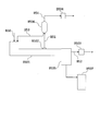
- the recovery apparatus shown in FIG. 1 is a stirred tank (pressure-resistant reactor) B101 in which a liquid phase component by-produced in the production process of compound (I) and at least one active hydrogen-containing compound are reacted; Condenser B102 for cooling the gas phase component by-produced in the reaction; Storage tank B103 for containing the liquid phase component generated in the decomposition reaction in the stirring tank B101; pressure permitting discharge of the gas phase component not condensed in the condenser B102 Holding valve B104 for holding the liquid; line B1 for supplying the liquid phase component by-produced in the production process of compound (I) to the stirring tank B101; line B2 for sending the gas phase component generated in the stirring tank B101 to the condenser B102; The condensate obtained by cooling in the vessel B102 is returned to the stirring vessel B101 in a line B3; the gas phase component not condensed in the condenser B102 is discharged; and the stirring vessel B1 Having a line B5 to send the resulting liquid phase component in 1
- the recovery apparatus shown in FIG. 1 may further include known process devices such as a liquid transfer pump, flowmeters, instrumentation devices such as a thermometer, and a heat exchanger, as necessary. Further, the recovery apparatus shown in FIG. 1 may be provided with a plurality of tank reactors connected as needed.
- FIG. 2 is a schematic configuration view showing another example of a recovery apparatus which is used in the recovery method of the present embodiment and (1) a tank-type reactor is used as a reactor.
- the recovery apparatus shown in FIG. 2 is a reaction tank (pressure-resistant reactor) B201 in which a liquid phase component by-produced in the production process of compound (I) and at least one active hydrogen-containing compound are mixed and reacted.
- Condenser B203 for cooling the gas phase component by-produced in the decomposition reaction;
- Storage tank B205 for containing the liquid phase component generated in the decomposition reaction in the reaction vessel B201; Permitting discharge of the gas phase component not condensed in the condenser B203 Pressure holding valve B 204; liquid phase component of reaction tank B 201 is extracted and returned to reaction tank B 201.
- Pump B 202 for stirring and circulating liquid phase components; liquid phase by-produced in production process of compound (I) Obtained by being cooled by a condenser B203; a line B20 for supplying the components to the reaction vessel B201; a line B24 for feeding the gas phase component by-produced in the reaction vessel B201 to the condenser B203; A line B23 for returning the condensate to the reaction vessel B201; a line B26 for discharging a gas phase component not condensed in the condenser B203; a liquid phase component withdrawn from the reaction vessel B201; and returning it to the reaction vessel B201; A line B21 for sending to the storage tank B205; and a line B25 for sending the liquid phase component extracted from the reaction tank B201 to the storage tank B205.
- the amount of liquid transfer by the pump B 202 is appropriately determined according to the amount of reaction liquid in the stirring tank B 201 and the materials to be used.
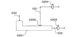
- FIG. 3 is a schematic configuration view showing another example of a recovery apparatus which is used in the recovery method of the present embodiment and (1) a tank-type reactor is used as a reactor.
- the recovery apparatus shown in FIG. 3 is a stirred tank (pressure-resistant reactor) B301 in which a liquid phase component by-produced in the production process of compound (I) and at least one active hydrogen-containing compound are mixed and reacted.
- liquid phase component obtained from the decomposition reaction of (a pressure-resistant reactor) B302 a condenser B303 for cooling a gas phase component by-produced in the decomposition reaction in the stirring vessel B301; generated in the decomposition reaction in the reaction vessel B302
- Storage tank B 305 containing liquid phase components
- Pressure holding valve B 304 holding pressure permitting discharge of gas phase components not condensed by the condenser B 303; liquid phase components by-produced in the production process of compound (I)
- the screw may be single-axial or multi-axial (for example, two-axial), but when the viscosity of the reaction liquid is high, or as described later, the extruder is provided with a degassing function to be a decomposition product.
- the decomposition reaction is carried out while extracting a part or all as a gas phase component from the extruder, the residual component may increase in viscosity or solidify, so multi-axial ones are preferred, and two-axial ones are more preferred.
- FIG. 4 is a schematic configuration view showing an example of a recovery device used in the recovery method of the present embodiment, and (2) an extruder is used as a reactor.
- the recovery apparatus shown in FIG. 4 is an extruder B401 in which a liquid phase component by-produced in the production process of compound (I) and an active hydrogen-containing compound are reacted; Condenser B405; Storage tank B406 containing liquid phase component generated by decomposition reaction in extruder B401; Pressure retaining valve B403 holding pressure permitting discharge of liquid phase component generated by decomposition reaction in extruder B401; Condenser Pressure holding valve B404 which holds a pressure permitting discharge of the gas phase component not condensed in B405; line B40 for supplying a liquid phase component by-produced in the production process of compound (I) to extruder B401; in extruder B401 A vent port B402 for extracting a gas phase component by-produced in the decomposition reaction; a line B41 for sending the gas phase component extracted from the vent port B
- FIG. 5 is a schematic block diagram which shows another example of the collection
- the recovery apparatus shown in FIG. 5 extracts the gas phase component by-produced in the decomposition reaction in the extruder B501 which makes the liquid phase component by-produced in the production process of compound (I) react with the active hydrogen-containing compound.
- the recovery apparatus shown in FIG. 5 is preferably used particularly when the residual component is in a state of high viscosity or solidification. It is preferable to provide a mechanism for recovering the decomposition products collected in the receiver 505 from the receiver 505 in order to continuously carry out the decomposition reaction.
- FIG. 6 is a schematic configuration view showing an example of a recovery apparatus which is used in the recovery method of the present embodiment and (3) a thin film evaporator is used as a reactor.
- the recovery apparatus shown in FIG. 6 is a schematic configuration view showing an example of a recovery apparatus which is used in the recovery method of the present embodiment and (3) a thin film evaporator is used as a reactor. The recovery apparatus shown in FIG.
- FIG. 6 is a thin film evaporator B602 having a heating evaporation surface B601 for reacting a liquid phase component by-produced in the production process of compound (I) with an active hydrogen-containing compound; decomposition reaction on the heating evaporation surface B601 Condenser B 604 for cooling the gas phase component by-produced in step; Recovery part B 603 for recovering the liquid phase component generated by decomposition reaction on heating evaporation surface B 601; Storage tank B 605 for containing the liquid phase component recovered in recovery part B 603; A pressure holding valve B606 which holds a pressure permitting discharge of the gas phase component not condensed in the condenser B604; a liquid phase component by-produced in the production process of compound (I) is supplied to the thin film evaporator B602; Line B64 for sending the vapor phase component by-produced on the evaporation surface B601 to the condenser B604; the condensate obtained by cooling the condenser B604 and returning it to
- the liquid phase component and the active hydrogen-containing compound supplied from the line B60 to the thin film evaporator B602 are spread in the form of a thin film on the thin film evaporator and the heating evaporation surface B601.
- the heating evaporation surface B601 is appropriately heated by an electric heater, an oil jacket or the like.
- the thin film evaporator B602 is not particularly limited as long as it is a known method, and may be a method of centrifugal dispersion, or a method of pressing the liquid against the heating evaporation surface B601 by a stirring blade to make a thin film.
- the liquid phase component developed on the heating evaporation surface B601 and the active hydrogen-containing compound cause a decomposition reaction.
- the gas phase component by-produced by the decomposition reaction on the heating evaporation surface B601 is extracted from the line B64 and introduced into the condenser B604.
- the condensate obtained by being cooled by the condenser B604 is supplied to the thin film evaporator B602 through the line B63.
- Gas phase components not condensed in the condenser B 604 are discharged through a line B 61 by a pressure holding valve B 606.
- the liquid phase component generated by the decomposition reaction on the heating evaporation surface B601 is transmitted along the surface of the heating evaporation surface B601 and is collected in the collection unit B603.
- the components recovered in the recovery unit B 603 are recovered in the storage tank B 605 through the line B 62. At that time, it is also preferable to provide a discharge mechanism for the agitating blade and the screw blade in the recovery unit B603.
- the stirring blades and screw blades of the recovery unit B603 may be connected to the same support drive as the thin film evaporator B602, or may be connected to a different support drive.
- the recovery method of the present embodiment preferably further includes the step (5) of separating the compound (III) from the liquid phase component (reaction liquid) discharged in the step (4).
- a known method can be used to separate the compound (III) from the reaction solution obtained in the step (4), for example, distillation separation, liquid-liquid separation, solid-liquid separation, membrane separation, etc.
- the said process (5) can also isolate
- the recovery method of the present embodiment preferably further includes the step (6) of purifying the compound (III) separated in the step (5).
- the method for purifying the compound (III) may be a known method, and examples thereof include distillation separation, liquid-liquid separation, solid-liquid separation, membrane separation and the like.
- the step (6) can also continuously produce the compound (III) separated continuously in the step (5). It is preferable to recycle the compound (III) recovered in the step (6) to the production process of the compound (I).
- the method for producing the compound (I) or the quality of the compound (I) produced by the method is often affected, so in step (6), relative to the total mass of the compound (III)
- the compound (III) is recovered by distillation such that the content of the metal component is 1000 ppm by mass or less and the content of the halogen atom is 1000 ppm by mass or less.
- Step (7) For example, when the above step (1) is carried out using a compound containing a carbamate group (—NH—C () O) —OR) as in the compounds represented by the above general formulas (XIII) to (XVI) The reaction with an active hydrogen-containing compound produces a hydroxy compound represented by ROH.
- X 41 is an aromatic hydrocarbon ring or a heteroaromatic ring having 6 to 12 carbon atoms.
- R 41 represents a substituent of X 41 and represents a C 1-20 alkyl group which may be substituted by a phenyl group and / or a hydroxyphenyl group, an amino group or a hydroxy group.
- n41 represents the number of substituents R 41 and represents an integer of 0 to 4, preferably 0 to 3. When n41 is 2 or more, R 41 may be the same or different.
- X 41 is an aromatic hydrocarbon ring or a heteroaromatic ring having 6 to 12 carbon atoms.
- an aromatic hydrocarbon ring although a benzene ring, a naphthalene ring, etc. are mentioned, for example, a benzene ring is preferable.
- heteroaromatic rings include pyridine rings and the like.
- phenol, tetramethylbutylphenol, di (dimethylbenzyl) phenol, heptylphenol, nonylphenol, tribenzylphenol, di-tert-aminophenol, phenylphenol, diisopropylphenol, tribenzylphenol, hydroquinone, bisphenol A Etc. are preferably exemplified.
- the compound (V) is separated from the reaction solution obtained in the step (4) together with the compound (III), and after the step (6), the following steps (7) It is preferable to recover a compound (V) by performing. (7) Step of purifying the above compound (V)
- the method for purifying the compound (V) separated in the step (5) may be a known method, and examples thereof include distillation separation, liquid-liquid separation, solid-liquid separation, membrane separation and the like.
- the step (7) can be performed simultaneously with the step (5) or the step (6), and the steps (1) to (5) can be performed continuously.
- the compound (V) recovered in the step (7) it is preferable to recycle the compound (V) recovered in the step (7) to the method for producing the compound (I). At that time, the production method of the compound (I) and the quality of the compound (I) produced by the method in many cases are affected, so in step (7), relative to the total mass of the compound (V)
- the compound (V) is recovered by distillation such that the content of the metal component is 1000 mass ppm or less and the content of the halogen atom is 1000 mass ppm or less.
- the method for recovering an organic amine according to the second embodiment of the present invention is a method for recovering a compound (III) from a liquid phase component containing a high boiling point compound by-produced in the method for producing a compound (I), Step (A), step (B) and step (4) are included.
- the description of the same configuration as that of the recovery method of the first embodiment may be omitted.
- the step (A) is a step of mixing a liquid phase component containing a high boiling point compound which is by-produced in the method for producing the compound (I), water, and the compound (III).
- the liquid phase component containing the high boiling point compound by-produced by the manufacturing method of compound (I) and compound (III) are as having described in the said 1st embodiment.
- the amount of water used in step (A) is a stoichiometric ratio with respect to the total molar amount of biuret group, allophanate group, isocyanurate group, carbamate group and urea group contained in the liquid phase component. Preferably, it is in the range of 1 to 200 times.
- the amount of the compound (III) used in the step (A) is preferably in the range of 0.01 times to 200 times the stoichiometric ratio (molar ratio) with respect to water.
- the contents of the biuret group, the allophanate group, the isocyanurate group, the carbamate group, the urea group and the fleece rearrangement terminal are as described in the first embodiment.
- the liquid phase component, water, and the compound (III) may be mixed in advance and supplied to the reactor for performing the step (B), or may be supplied separately and mixed in the reactor. Moreover, it can also be preheated before supplying to the reactor which performs a process (B) in the range which does not have an obstacle in the essence of this embodiment.
- Step (B) is a step of reacting the liquid phase component with water in a reactor.
- the temperature in the reactor in step (B) is preferably in the range of 100 ° C. to 350 ° C., more preferably in the range of 150 ° C. to 330 ° C., and still more preferably in the range of 200 ° C. to 300 ° C.
- the pressure in the reactor is preferably in the range of 0.01 kPa or more and 15 MPa or less (absolute pressure), and may be carried out under reduced pressure, normal pressure or increased pressure. In view of the above preferable temperature range and the compound etc.
- the implementation under pressure is preferable, the range of 0.101 MPa or more and 15 MPa or less (absolute pressure) is more preferable, and 0.5 MPa or more and 13 MPa or less (absolute pressure) The range of 2 MPa or more and 8 MPa or less (absolute pressure) is particularly preferable.
- the reaction time in the case of continuous reaction, residence time) is preferably 0.01 hour to 100 hours, and the reaction solution is appropriately sampled to measure the amount of compound (III) which is the target compound. The time to reach the desired amount of production can be the reaction time.
- the step (4) is a step of discharging the reaction liquid containing the compound (III) as a liquid phase component in the reactor to the outside of the reactor, and is carried out in the same manner as the first embodiment. Can.
- Recovery device Although the same recovery device as that of the first embodiment can be used as a recovery device used in the recovery method of this embodiment, the recovery device described below can also be used.
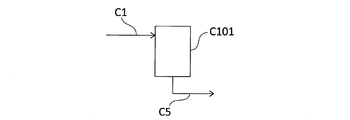
- FIG. 8A is a schematic configuration view showing an example of a recovery apparatus used in the recovery method of the present embodiment, and (1) a tank-type reactor is used as a reactor.
- the recovery apparatus shown in FIG. 8A is a stirring tank (pressure-resistant reactor) C101 in which a liquid phase component by-produced in the production process of compound (I) and water are reacted; a liquid phase by-produced in the production process of compound (I) A line C1 for supplying the component, water and the compound (III) to the stirring tank C101; and a line C5 for discharging the liquid phase component obtained in the stirring tank C101.
- the recovery apparatus shown in FIG. 8A may further include known process devices such as a liquid transfer pump, flowmeters, instrumentation devices such as a thermometer, and a heat exchanger, as necessary.
- FIG. 8B is a schematic configuration view showing another example of the recovery device used in the recovery method of the present embodiment, which is a (1) tank type reactor as a reactor.
- a stirring tank (pressure-resistant reactor) C101 in which a liquid phase component by-produced in the production process of compound (I) and water are reacted; Reservoir C103 to be accommodated; Pressure holding valve C104 for holding a pressure permitting discharge of the gas phase component by-produced in the stirring tank C101; liquid phase component by-produced in the production process of compound (I) Are supplied to the stirring tank C101; a line C4 for discharging the gas phase component generated in the stirring tank C101; and a line C5 for sending the liquid phase component obtained in the stirring tank C101 to the storage tank C103.
- a stirring tank (pressure-resistant reactor) C101 in which a liquid phase component by-produced in the production process of compound (I) and water are reacted
- Reservoir C103 to be accommodated
- Pressure holding valve C104 for holding a pressure permitting discharge of the
- the recovery apparatus illustrated in FIG. 8B may further include known process devices such as a liquid transfer pump, flowmeters, instrumentation devices such as a thermometer, and a heat exchanger, as necessary. Moreover, the recovery apparatus shown to FIG. 8B may connect and comprise several tank-type reactors as needed.
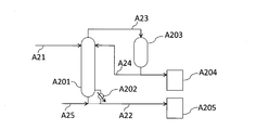
- FIG. 9 is a schematic configuration view showing an example of a recovery device used in the recovery method of the present embodiment, and (2) an extruder is used as a reactor.
- the recovery apparatus shown in FIG. 9 is an extruder C201 in which a liquid phase component by-produced in the production process of compound (I) and water are reacted; a vent port C202 for extracting a gas phase component by-produced in the decomposition reaction in the extruder C201; Pressure holding valve C203 which holds the pressure which permits discharge of the liquid phase component generated in the decomposition reaction in the extruder C201; pressure holding valve C204 which holds the pressure which allows discharge of the gas phase components byproduced in the extruder C201; Line C20 for supplying the liquid phase component by-produced in the production process of (I), water and compound (III) to the extruder C201; line C21 for discharging gas phase components extracted from the vent port C202; and extruder It has a line C22 for discharging the liquid phase component obtained in C201.
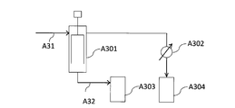
- FIG. 10 is a schematic block diagram which shows another example of the collection
- a pressure holding valve C304 which holds a pressure permitting discharge of the gas phase component from the vent port C302; a receiver C305 which recovers a liquid phase component discharged from the extruder C301; allowing the discharge of the liquid phase component from the receiver C305; Pressure holding valve C303; liquid phase component by-produced in compound (I) production process, water and compound (III) line C30 for supplying extruder C301; gas phase component extracted from vent port C302 And a line C32 for discharging the liquid phase component from the receiver C305.
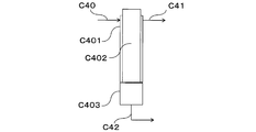
- FIG. 11 is a schematic configuration view showing an example of a recovery apparatus which is used in the recovery method of the present embodiment and (3) a thin film evaporator is used as a reactor.
- the recovery apparatus shown in FIG. 11 was produced by a decomposition reaction on a thin-film evaporator C402 having a heating evaporation surface C401 for reacting liquid phase components by-produced in the production process of compound (I) with water; Recovery part C403 for recovering liquid phase components; line C40 for supplying liquid phase components, water and compound (III) by-produced in the production process of compound (I) to thin-film evaporator C402; A line C41 for discharging a gas phase component; and a line C42 for discharging a liquid phase component from the recovery unit C403.
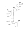
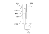
- FIG. 7 is a schematic configuration view showing another example of a recovery apparatus which is used in the recovery method of the present embodiment and (3) a thin film evaporator is used as a reactor.
- the recovery apparatus shown in FIG. 7 has a heating evaporation surface B 701 in which a liquid phase component by-produced in the production process of compound (I) and an active hydrogen-containing compound are reacted, and a vapor phase by-produced by decomposition reaction in the heating evaporation surface B 701.
- NMR analysis method Device JNM-A400 FT-NMR system manufactured by Nippon Denshi Co., Ltd. Japan Preparation of 1 H-NMR analysis sample 0.3 g of a sample solution was weighed, and 0.7 g of heavy chloroform was used. A solution in which 0.05 g of tetramethyl tin was added as an internal standard substance and uniformly mixed was used as an NMR analysis sample. -Quantitative analysis method The analysis was performed for each standard substance, and the quantitative analysis of the analysis sample solution was performed based on the prepared calibration curve.
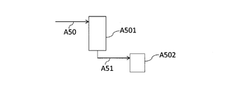
- the apparatus shown in FIG. 12 was used.
- Continuous multistage distillation column A101 is an apparatus for performing a carbamate process,
- the bottom temperature was 250 degreeC by heating with reboiler A111, and it was referred to as 5 kPa top pressure.
- the reaction solution was withdrawn at 90.7 kg / hr from the bottom of the continuous multistage distillation column A101.
- the gas phase component was extracted from the top of continuous multistage distillation column A101, and was introduced into condenser A103 through line A3.
- the gas phase component introduced into the condenser A103 was cooled to 100 ° C. by the condenser A103 to obtain a mixed liquid of 4- (1,1,3,3-tetramethylbutyl) phenol and urea.
- line A4 a mixture of 4- (1,1,3,3-tetramethylbutyl) phenol and urea obtained in condenser A103 was supplied to line A1 at 9 kg / Hr.
- the gas phase components not condensed in the condenser A103 were discharged from the condenser A103 through a line A9.
- the reaction solution was supplied from the bottom of the continuous multistage distillation column A101 to the thermal decomposition apparatus A102 through a line A5.
- the thermal decomposition apparatus A102 is an apparatus for producing an isocyanate by a thermal decomposition reaction of carbamate, and comprises a tubular reactor and a separation tank for separating the liquid phase component and the gas phase component containing isocyanate. .
- the internal pressure was set to 1 kPa, and was heated to 250 ° C. by external heating.
- the gas phase component generated in the thermal decomposition apparatus A102 is supplied at 8 m / s from the line A7 to the separation tower A109, and 4- (1,1,3,3-tetramethylbutyl) phenol and 2,4-toluene diisocyanate The separation was done.
- the amount of heat required for distillation separation was supplied from reboiler A112.
- 4- (1,1,3,3-tetramethylbutyl) phenol was recovered from line A18 from the bottom of separation column A109.
- the component containing 2,4-toluene diisocyanate recovered from the top of separation column A109 was supplied to purification column A110 via condenser A114 and line A20 to carry out distillation purification of 2,4-toluene diisocyanate.
- the heat quantity required for distillation purification was supplied from reboiler A113.
- 2,4-toluene diisocyanate was recovered at 2.4 kg / Hr via a condenser A115 and a line A17.
- the bottom component of the purification column A110 was withdrawn from line A19.
- a portion of the liquid phase component recovered from the bottom of the thermal decomposition apparatus A102 was recovered through line A8, and the liquid temperature was set to 180 ° C., and was supplied as a liquid phase component containing a high boiling point compound to the following step (1-1).
- the other liquid phase components were again supplied to the thermal decomposition apparatus A 102 through line A6.
- the unit immersion side flow rate at the bottom of the thermal decomposition apparatus A 102 was 50 kg / m ⁇ hour.
- the viscosity at 150 ° C. of the liquid phase component recovered from line A8 was 70 mPa ⁇ s.
- the liquid phase component recovered from line A8 is analyzed by 1 H-NMR to find that 0.90 mol of carbamate bond, 1 group (II-1) and 1 group (II-2) are combined per 1 kg of liquid phase component. .13 moles, 0.12 moles of allophanate bond and isocyanurate bond combined, 0.22 mole of Fries rearrangement end.
- the liquid phase component contains a compound represented by the following formula (1-a-1) and a compound represented by the following formula (1-b-1), It contained 57% by mass of 1,1,3,3-tetramethylbutyl) phenol.
- Step (1-1) Step of reacting a liquid phase component containing a high boiling point compound with an active hydrogen-containing compound
- An apparatus shown in FIG. 1 was used. 50 kg of the liquid phase component containing the high boiling point compound recovered through the line A8 was supplied to the pressure resistant reactor B101 through the line B1 in a state of being maintained at 180 ° C. Next, 100 kg of water was supplied to the pressure resistant reactor B101 to make a mixed solution. The pressure-resistant reactor B101 was heated at 280 ° C. and a pressure of 6.5 MPa for 5 hours.
- the gas phase component in the pressure container B101 is condensed via the line B3 to the condenser B102 Introduced to The gas phase component introduced into the condenser B102 was cooled to 10 ° C. by the condenser B102 to obtain a condensate, which was returned to the pressure resistant vessel B101 through the line B2. This step was continued while the step (1-1) was being performed.
- Step (1-3) Step of discharging non-condensed gas phase component to other than the reactor The gas phase component not condensed in the above step (1-2) As a result of analysis, carbon dioxide was extracted as the main component). This step was continued while the step (1-1) was being performed.
- Step (1-4) Step of discharging the reaction solution to the outside of the reactor
- the step (1-1) was performed, and after cooling, the reaction solution was recovered in the storage tank B103 through the line B5.
- the reaction mixture was analyzed by gas chromatography to find that 8.3 moles of 2,4-toluenediamine was contained.
- Step (1-5) Step of separating compound (III) The recovered reaction liquid was distilled under reduced pressure to recover crude 2,4-toluenediamine. The yield was 80%.
- the crude 2,4-toluenediamine recovered in the above step (1-5) was purified by distillation.
- the recovered 2,4-toluenediamine had a purity of 99% by mass or more (including an analysis error of gas chromatography).
- the metal atom content relative to the total mass of 2,4-toluenediamine was less than 1000 ppm, and the halogen atom content was less than 1000 ppm.
- Step (1-7) Step of separating compound (V) The residual liquid after recovering compound (III) in the above step (1-5) is distilled under reduced pressure to obtain crude 4- (1,1,3,3) 3-Tetramethylbutyl) phenol was recovered. The yield was 81%.
- Step (1-8) Step of purifying compound (V)
- the recovered 4- (1,1,3,3-tetramethylbutyl) phenol had a purity of 99% by mass or more (including an analysis error of gas chromatography).
- the metal atom content relative to the total mass of 4- (1,1,3,3-tetramethylbutyl) phenol was less than 1000 ppm, and the halogen atom content was less than 1000 ppm.
- the mixture was supplied to line A1 continuously to multistage distillation column A101 to carry out step (1-A).
- 2,4-toluene diisocyanate was recovered from line 17 at 2.4 kg / Hr.
- Example 2 Process (2-A) (Production of carbamate)
- the carbamate process was carried out using the apparatus shown in FIG.
- a mixture of 11.3 kg of 1-amino-3-aminomethyl-3,5,5-trimethylcyclohexane, 15.1 kg of urea and 220.3 kg of 1-butanol was supplied to the continuous multistage distillation column A201 at 20 kg / hr from line A21.
- 1-Butanol was suitably supplied from line A25.
- the gas phase components generated in the continuous multistage distillation column A201 were introduced into the condenser A203 through the line A23.
- the gas phase component introduced into the condenser A203 was cooled to 0 ° C. to obtain a mixture of 1-butanol and urea.
- a portion of the mixed solution was supplied to the continuous multistage distillation column A201 at 3.5 kg / Hr from the line A24, and the remaining portion was collected in the storage tank A204.
- the continuous multistage distillation column A201 is an apparatus for performing a carbamate process, and the bottom temperature is adjusted to 220 ° C. and the top pressure is 1.2 MPa by heating with a reboiler A202.
- the reaction liquid was extracted from the bottom of the continuous multistage distillation column A201, and was collected in the storage tank A205 through the line A22.
- a preconcentration step was performed using the apparatus shown in FIG.
- the reaction liquid collected in the storage tank A205 in the carbamate forming step was supplied to the thin film evaporator A301 at 21 kg / Hr through the line A31.
- the temperature of the heating evaporation surface was 130 ° C.
- the internal pressure was 70 kPa.
- the gas phase component generated by the thin film evaporator A301 was condensed by the condenser A302 and recovered to the storage tank A304. The recovery was 1-butanol.
- the liquid phase component generated by the thin film evaporator A301 was recovered at 10 kg / Hr in the storage tank A303 via the line A32.
- the thermal decomposition process was performed using the apparatus shown in FIG.
- the thermal decomposition apparatus A401 is a multistage distillation column for producing isophorone diisocyanate by the thermal decomposition reaction of N-substituted carbamate, and the pressure at the top of the column is 25 kPa and heating with a reboiler A403 gives a total reflux condition of dibenzyl ether did.
- the liquid phase component recovered to the storage tank A 303 in the preconcentration step from line A40 was supplied at 5 kg / Hr, and dibenzyl ether was supplied from line A49.
- the gas phase component was withdrawn from the top of the column, and was recovered from the line A42 via the condenser A402, and the liquid phase component was recovered from the line A41.
- the fraction containing isophorone diisocyanate was recovered from a line A43 provided in the middle stage of the thermal decomposition apparatus A401 and supplied to the separation column A404.
- the gas phase component containing 1-butanol was separated by distillation in separation column A404, and the gas phase component was recovered from line A44 via condenser A405.
- the amount of heat required for distillation separation was supplied from reboiler A406.
- the liquid phase component recovered from the bottom of separation column A404 was supplied to separation column A407 via line A45 and line A46.
- separation column A407 liquid phase components were separated by distillation and recovered from the line A48.
- the heat required for distillation separation in separation column A407 was supplied from reboiler A409.
- the gas phase component recovered from the top of the separation column A404 was condensed by the condenser A408, and isophorone diisocyanate was recovered from the line A47.
- the liquid phase component recovered from line A41 was used as the liquid phase component containing the high boiling point compound of the present embodiment.
- the viscosity of the liquid phase component containing the high boiling point compound was 40 mPa ⁇ s at 150 ° C.
- the liquid phase component was analyzed by 1 H-NMR to find that 2.56 mol of a carbamate bond, 0.14 mol of a combination of the group (II-1) and the group (II-2) were obtained per 1 kg of the liquid phase component.
- the combination of allophanate bond and isocyanurate bond was a mixture containing 0.10 mol and dibenzyl ether.
- the liquid phase component was analyzed by liquid chromatography, and it contained a compound represented by the following formula (2-a-1) and a compound represented by the following formula (2-b-1).
- An apparatus shown in FIG. 2 was used. 50 kg of the liquid phase component containing the high boiling point compound recovered through the line A41 was supplied to the pressure resistant reactor B201 through the line B20 while being maintained at 180 ° C. After adding 100 kg of water and 16 kg of ethanol to the pressure resistant reactor B201, the reaction was carried out at 250 ° C. and 4.3 MPa for 5 hours while circulating the liquid phase component by the pump B202 via the line B21 and the line B22.
- the gas phase component in the pressure resistant reactor B201 is passed through the line B24 It was introduced into the condenser B203.
- the condensate obtained by cooling the introduced gas phase component to 10 ° C. in the condenser B203 was returned to the pressure resistant reactor B201 through the line B23. This process was continued while performing the process (2-1).
- Step (2-3) The step of discharging the non-condensed gas phase component out of the reactor Other than the step (2-2), the gas phase component not condensed in the step (2-2) It was extracted through line B26 as carbon dioxide was the main component). This process was continued while performing the process (2-1).
- Step (2-4) Step of discharging the reaction solution out of the reactor Step (2-1) was carried out, and after cooling, the reaction solution was recovered through line B25 into the storage tank B205.
- the reaction solution was analyzed by gas chromatography to find that it contained 1-amino-3-aminomethyl-3,5,5-trimethylcyclohexane.
- Step (2-5) Step of separating compound (III) The recovered reaction liquid was distilled under reduced pressure to recover crude 1-amino-3-aminomethyl-3,5,5-trimethylcyclohexane. The yield was 90%.
- Step (2-6) Step of purifying compound (III)
- the crude 1-amino-3-aminomethyl-3,5,5-trimethylcyclohexane recovered in step (2-5) was purified by distillation.
- the recovered 1-amino-3-aminomethyl-3,5,5-trimethylcyclohexane had a purity of 99% by mass or more (including an analysis error of gas chromatography).
- the metal atom content relative to the total mass of 1-amino-3-aminomethyl-3,5,5-trimethylcyclohexane was less than 1000 ppm, and the halogen atom content was less than 1000 ppm.
- Step (3-A) Step of obtaining a liquid phase component containing a high boiling point compound by-produced in the production of compound (I) (production of carbamate)
- the apparatus shown in FIG. 16 was used. 50 kg of phenol was supplied to the stirred tank A 501 through the line 50, and then 38 kg of diphenyl carbonate was supplied to make a uniform solution. While the stirring vessel A501 was kept at 40 ° C., 15 kg of 4,4′-dicyclohexylmethanediamine was slowly added. Stirring was continued for 5 hours after the addition was completed, and then the reaction solution was transferred to the storage tank 502 through the line A51.
- Thermal decomposition of carbamate The same method as “thermal decomposition of carbamate” in Example 2 was followed to obtain a liquid phase component containing dicyclohexylmethane diisocyanate and a high boiling point compound.
- the viscosity of the liquid phase component containing the high boiling point compound was 50 mPa ⁇ s at 150 ° C.
- the liquid phase component containing the high-boiling point compound is analyzed by 1 H-NMR to find that 2.67 mol of carbamate bond, group (II-1) and group (II-2) are combined per 1 kg of liquid phase component.
- the liquid phase component containing the said high boiling point compound is a compound represented by the following formula (3-a-1) and the following formula (3- It contained the compound represented by b-1).
- Step (3-1) Step of reacting a liquid phase component containing a high boiling point compound with an active hydrogen-containing compound
- the apparatus shown in FIG. 3 was used. In a state where 50 kg of the liquid phase component containing the high boiling point compound recovered in the step (3-A) is maintained at 180 ° C., it is supplied to the stirring tank B301 through the line B30. 100 kg of water and 50 kg of methanol were added to the stirring tank B301 to obtain a uniform solution at 250 ° C. and 4.9 MPa. The solution was continuously supplied to a stirring tank B302 which was heated to 250 ° C. and pressurized to 4.9 MPa through a line B33. The gas phase component generated in the stirring tank B302 was introduced into the stirring tank B301 through the line B34.
- the gas phase component in the stirring tank B301 is condensed via the line B32 to the condenser B303. Introduced to The introduced gas phase component was cooled to 5 ° C. in a condenser B 303 to obtain a condensate. The obtained condensate was returned to the stirring tank B301 through the line B31. This step was continued while performing step (3-1).
- Step (3-3) The step of discharging the non-condensed gas phase component to the other part of the reactor The gas phase component not condensed in the step (3-2) It extracted through line B36 as carbon was a main component. This step was continued while performing step (3-1).
- Step (3-4) Step of discharging the reaction solution to the outside of the reactor
- the reaction solution was collected in the storage tank B 305 from the bottom of the stirring tank B 302 through the line 35.
- the average residence time was 3 hours.
- the reaction liquid obtained was analyzed by gas chromatography, and it was found that 4,4′-dicyclohexylmethanediamine was contained.
- the crude 4,4′-dicyclohexylmethanediamine recovered in step (3-5) was purified by distillation.
- the recovered 4,4′-dicyclohexylmethanediamine had a purity of 99% by mass or more (including an analysis error of gas chromatography).
- the metal atom content relative to the total mass of 4,4′-dicyclohexylmethanediamine was less than 1000 ppm, and the halogen atom content was less than 1000 ppm.
- a reaction solution was prepared in the same manner as in "Preparation of carbamate" in Example 3 except that 50 kg of phenol, 38 kg of diphenyl carbonate and 8.2 kg of 1,6-hexamethylenediamine were used using the apparatus shown in FIG. I got The reaction liquid was analyzed by liquid chromatography, and it was found that the carbamate represented by the following formula (4-1) was produced at a yield of 95% with respect to 1,6-hexamethylenediamine.
- Thermal decomposition of carbamate The same method as “thermal decomposition of carbamate” in Example 1 was performed to obtain a liquid phase component containing a high boiling point compound.
- the liquid phase component containing the high-boiling point compound is analyzed by 1 H-NMR to find that 2.05 moles of a carbamate bond per kg of liquid phase component, the group (II-1) and the group (II-2) are combined It was a mixture containing 0.19 mol, 0.48 mol of allophanate bond and isocyanurate bond, 0.02 mol of Fries transition terminal and 1.25 mol of 4- ( ⁇ , ⁇ -dimethylbenzyl) phenol.
- the liquid phase component containing this high boiling point compound is a compound represented by the following formula (4-a-1) and the following formula (4- It contained the compound represented by b-1).
- Step (4-1) Step of reacting a liquid phase component containing a high boiling point compound with an active hydrogen-containing compound
- the apparatus shown in FIG. 4 was used. 50 kg of the liquid phase component containing the high boiling point compound recovered in the step (4-A) was heated to 280 ° C. through the line B 40 while being maintained at 180 ° C. and supplied to the extruder B 401 pressurized at 6.7 MPa . Water was continuously added to the extruder B401 at a rate of 100 kg based on 50 kg of the liquid phase component containing the high boiling point compound.
- Step (4-2) returning the condensate obtained by cooling the gas phase component back into the reactor Step (4-1) in which the gas phase component of the extruder B 401 is included in the extruder B 401 It extracted from the mouth B402 through the line 41, and introduced it into the condenser B405. The introduced gas phase component was cooled in a condenser B 405 to obtain a condensate. The resulting condensate was returned to extruder B401 through line B43. During the step (4-1), this step was continued.
- Step (4-3) The step of discharging the non-condensed gas phase component to the other part of the reactor The gas phase component not condensed in the step (4-2) It extracted through line B44 as carbon was a main component. During the step (4-1), this step was continued.
- Step (4-4) Step of discharging the reaction liquid out of the reactor
- the reaction liquid was collected into the storage tank B406 by the pressure holding valve B403 from the discharge port of the extruder 401 through the line.
- the reaction mixture was analyzed by gas chromatography to find that it contained 1,6-hexamethylenediamine.
- the crude 1,6-hexamethylenediamine recovered in step (4-5) was purified by distillation.
- the recovered 1,6-hexamethylenediamine had a purity of 99% by mass or more (including an analysis error of gas chromatography).
- the metal atom content relative to the total mass of 1,6-hexamethylenediamine was less than 1000 ppm, and the halogen atom content was less than 1000 ppm.
- Step (4-7) Step of separating compound (V) The remaining liquid after recovering 1,6-hexamethylenediamine in step (4-5) is distilled under reduced pressure to obtain crude 4- ( ⁇ , ⁇ - Dimethylbenzyl) phenol was recovered. The yield was 74%.
- Step (4-8) Step of purifying compound (V)
- the crude 4- ( ⁇ , ⁇ -dimethylbenzyl) phenol recovered in step (1-7) was purified by distillation.
- 4- ( ⁇ , ⁇ -dimethylbenzyl) phenol had a purity of 99% by mass or more (including analysis error of gas chromatography).
- the metal atom content relative to the total mass of 4- ( ⁇ , ⁇ -dimethylbenzyl) phenol was less than 1000 ppm, and the halogen atom content was less than 1000 ppm.
- Step (5-A) Step of obtaining a liquid phase component containing a high boiling point compound by-produced in the production of compound (I) (production of a compound having a ureido group)
- the apparatus shown in FIG. 18 was used. 10.3 kg of urea and 261.9 kg of 4- (1,1,3,3-tetramethylbutyl) phenol were fed to a stirring tank A701 through a line A70. After making a homogeneous solution at 130 ° C., 9.8 kg of 2,4-toluenediamine was added and the mixture was stirred for 5 hours, and the reaction solution was recovered through line 71 into storage tank 702. The reaction liquid was analyzed by liquid chromatography to find that the compound represented by the following formula (5-1) was produced in 90% yield to 2,4-toluenediamine.
- Thermal decomposition of carbamate The same method as “thermal decomposition of carbamate” in Example 1 was performed to obtain a liquid phase component containing a high boiling point compound. The viscosity at 150 ° C. of the obtained liquid phase component was 82 mPa ⁇ s.
- the liquid phase component containing the high-boiling point compound is analyzed by 1 H-NMR to find that 1.33 moles of a carbamate bond per kg of the liquid phase component, the bond represented by the formula (II-1) and the formula (II-)
- the combined bonds represented by 2) contained 0.10 moles, the combined allophanate bonds and isocyanurate bonds contained 0.10 moles, and the Fleece rearrangement end 0.16 moles.
- the liquid phase component containing the high boiling point compound is a compound represented by the following formula (5-a-1), and the following formula (5) It contained 42% by mass of 4- (1,1,3,3-tetramethylbutyl) phenol including the compound represented by -b-1).
- Step (5-1) Step of reacting a liquid phase component containing a high boiling point compound with an active hydrogen-containing compound
- the apparatus shown in FIG. 5 was used. 50 kg of the liquid phase component containing the high boiling point compound recovered in the step (5-A) was heated to 280 ° C. through the line B 50 while being maintained at 180 ° C., and was supplied to the extruder B 501 pressurized at 6.7 MPa. Water was continuously added to the extruder B501 at a rate of 100 kg based on 50 kg of the liquid phase component containing the high boiling point compound.
- the gas phase component produced by the extruder B501 in the step (5-1) is an extruder B501. It extracted from the vent port B502 equipped with through line 51, and introduced it into condenser B506. The introduced gas phase component was cooled to 10 ° C. in a condenser B 506 to obtain a condensate. The obtained condensate was returned to extruder B501 through line B53. This step was continued while performing step (5-1).
- Step (5-3) The step of discharging the non-condensed gas phase component out of the reactor Other than the above-mentioned reactor
- the gas phase component not condensed in the step (5-2) It extracted through line B54 as carbon was a main component. This step was continued while performing step (5-1).
- Step (5-4) Step of discharging the reaction liquid to the outside of the reactor
- the reaction liquid collected in the receiver B505 provided in the discharge part of the extruder B501 is stored via the line B55. It collected to B507.
- the recovered reaction solution was analyzed by gas chromatography to find that it contained 2,4-toluenediamine.
- Step (5-5) Step of separating compound (III) The recovered reaction liquid was distilled under reduced pressure to recover crude 2,4-toluenediamine. The yield was 73%.
- Step (5-6) Step of purifying compound (III)
- the crude 2,4-toluenediamine recovered in step (5-5) was purified by distillation.
- the recovered 2,4-toluenediamine had a purity of 99% by mass or more (including an analysis error of gas chromatography).
- the metal atom content relative to the total mass of 2,4-toluenediamine was less than 1000 ppm, and the halogen atom content was less than 1000 ppm.
- the crude 4- (1,1,3,3-tetramethylbutyl) phenol recovered in step (5-7) was purified by distillation.
- the recovered 4- (1,1,3,3-tetramethylbutyl) phenol had a purity of 99% by mass or more (including an analysis error of gas chromatography).
- the metal atom content relative to the total mass of 4- (1,1,3,3-tetramethylbutyl) phenol was less than 1000 ppm, and the halogen atom content was less than 1000 ppm.
- the liquid phase component containing the high boiling point compound has many insoluble components at the time of sample preparation, and it is filtered through a filter and only soluble components are analyzed by 1 H-NMR, the result is group (II-1) and group (II-) The presence of the compound having 2) was confirmed.
- Process (6-1) The apparatus shown in FIG. 6 was used. In a state of holding 50 kg of the distillation residue of step (6-A) and 300 ° C., 50 kg of water and 30 kg of ethanol were mixed, and the mixture was supplied to thin-film evaporator B602 through line B60. The supplied mixed solution was developed in a thin film form on a heating evaporation surface B601 heated to 280 ° C. at 6.7 MPa.
- the gas phase component by-produced by the decomposition reaction on the heating evaporation surface B601 Were withdrawn from line B64 and introduced into condenser B604.
- the condensate obtained by cooling to 10 ° C. in the condenser B604 was returned to the thin film evaporator B602 through the line B63. This step was continued while performing step (6-1).
- Step (6-3) The step of discharging the non-condensed gas phase component out of the reactor Other than the step (6-2) The gas phase component not condensed in the step (6-2) It extracted through line B61 as carbon was a main component. This step was continued while performing step (6-1).
- the reaction liquid generated by the decomposition reaction on the heating evaporation surface B601 is transmitted along the surface of the heating evaporation surface B601 and recovered.
- Part B603 was collected.
- the components recovered in the recovery unit B 603 are recovered in the storage tank B 605 through the line B 62.
- the recovered reaction solution was analyzed by gas chromatography to find that it contained 2,4-toluenediamine.
- Step (6-5) Step of separating compound (III) The recovered reaction liquid was distilled under reduced pressure to recover crude 1,5-pentamethylenediamine.
- Step (6-6) Step of purifying compound (III)
- the crude 1,5-pentamethylenediamine recovered in step (6-5) was purified by distillation.
- the recovered 1,5-pentamethylenediamine had a purity of 99% by mass or more (including analysis error of gas chromatography).
- the metal atom content relative to the total mass of 1,5-pentamethylenediamine was less than 1000 ppm, and the halogen atom content was less than 1000 ppm.
- Step (7-A) Step of obtaining liquid phase component containing high-boiling point compound by-produced in production of compound (I)
- step (6-A) of Example 6 1,5-pentamethylene
- the diamine was prepared and the composition containing the high boiling point compound was recovered.
- the liquid phase component containing the high-boiling point compound has a large amount of insoluble components at the time of sample preparation, and it is filtered through a filter and only solubles are analyzed by 1 H-NMR. The presence of the compound having 2) was confirmed.
- Process (7-1) The apparatus shown in FIG. 7 was used. 50 kg of water and 50 kg of water and 25 kg of 1,5-pentamethylenediamine were mixed while maintaining 50 kg of the distillation residue of step (7-A) at 300 ° C., and the mixture was supplied to thin-film evaporator B702 through line B70. The supplied mixture was spread in a thin film on a heating evaporation surface B 701 heated to 280 ° C. under 6.7 MPa. The gas phase components were cooled to 50 ° C. in a condenser B704, and the condensed liquid was discharged through a line B73.
- Step (7-2) Step of discharging the reaction solution to the outside of the reactor
- the reaction solution is collected in the recovery unit B 703 provided at the bottom of the thin film evaporator, and then discharged through the line B 72 did.
- the discharged reaction solution was analyzed by gas chromatography and found to contain 1,5-pentamethylenediamine.
- Step (7-3) Step of separating compound (III) The discharged reaction solution was distilled under reduced pressure to recover crude 1,5-pentamethylenediamine.
- Step (7-4) Step of purifying compound (III)
- the crude 1,5-pentamethylenediamine recovered in step (7-3) was purified by distillation.
- the recovered 1,5-pentamethylenediamine had a purity of 99% by mass or more (including analysis error of gas chromatography).
- the metal atom content relative to the total mass of 1,5-pentamethylenediamine was less than 1000 ppm, and the halogen atom content was less than 1000 ppm.
- Examples 8 to 52 By combining the methods described in Examples 1 to 7 above, liquid phase components containing high-boiling compounds by-produced in production of compound (I) are obtained, and liquid phase components containing high-boiling compounds and active hydrogen-containing compounds are obtained.
- Step (1) of reacting in the reactor step (2) of returning the condensate obtained by cooling the gas phase components in the reactor into the reactor (2), reactor of the gas phase components not condensed Step (3) of discharging to another, step (4) of discharging liquid phase component in the reactor out of the reactor, step (5) of separating compound (III), step of purifying compound (III) (6 ), Step (7) of separating compound (V), and step of producing compound (V).
- step (1) of reacting in the reactor step (2) of returning the condensate obtained by cooling the gas phase components in the reactor into the reactor (2), reactor of the gas phase components not condensed Step (3) of discharging to another, step (4) of discharging liquid phase component in the reactor out of the reactor, step (5) of separating compound (
- the organic primary amine used as the active hydrogen compound is not included in the yield of the organic primary amine.
- Comparative Example 1 A crude 2,4-toluenediamine was recovered by the same method as in Example 1 except that the condenser B 102 was not cooled and the step corresponding to the step (1-2) in Example 1 was not performed. The yield was 38%. In addition, crude 4- (1,1,3,3-tetramethylbutyl) phenol was recovered. The yield was 43%.
- Comparative Example 2 The same method as in Example 2 was carried out except that the condenser B203 was not cooled and the step corresponding to the step (2-2) in Example 2 was not carried out, and crude 1-amino-3-aminomethyl-3, The 5,5-trimethylcyclohexane was recovered. The yield was 41%.
- Comparative Example 3 A crude 4,4′-dicyclohexylmethanediamine was recovered by the same method as in Example 3 except that the condenser 303 was not cooled and the step corresponding to the step (3-2) in Example 3 was not performed. . The yield was 42%.
- Comparative Example 4 The crude 1,6-hexamethylenediamine was recovered in the same manner as in Example 4 except that the condenser 405 was not cooled and the step corresponding to the step (4-2) in Example 4 was not performed. The yield was 37%. In addition, crude 4- ( ⁇ , ⁇ -dimethylbenzyl) phenol was recovered. The yield was 46%.
- Comparative Example 5 A crude 2,4-toluenediamine was recovered by the same method as in Example 5 except that the condenser 506 was not cooled and the step corresponding to the step (5-2) of Example 5 was not performed. The yield was 48%. In addition, crude 4- (1,1,3,3-tetramethylbutyl) phenol was recovered. The yield was 35%.
- Comparative Example 6 A crude 1,5-pentamethylenediamine was recovered by the same method as in Example 6 except that the condenser 604 was not cooled and the step corresponding to the step (6-2) in Example 6 was not performed. The yield was 32%.
- useful components such as an organic amine compound, can be efficiently collect
Abstract
Description
本願は、日本に、2017年12月27日に出願された特願2017-252607号と2018年1月30日に出願された特願2018-014143に基づき優先権を主張し、その内容をここに援用する。 The present invention relates to a method for recovering active components such as organic amine compounds and aromatic hydroxy compounds from liquid phase components produced in the production of isocyanate.
Priority is claimed on Japanese Patent Application No. 2017-252607, filed Dec. 27, 2017, and Japanese Patent Application No. 2018-014143, filed Jan. 30, 2018, the contents of which are incorporated herein by reference. In the
イソシアネート化合物の製造方法として、主原料となる有機アミン化合物及び副原料としてホスゲンを使用する方法、有機アミン化合物及び炭酸エステルや尿素を使用する方法が知られている。
これらのイソシアネート化合物の製造方法においては、生成するカルバメートやNCO化合物、又は、それらの中間体等が、例えば、多量化、ビウレット化及びアロファネート化等の重合反応を惹起することが知られており、製造過程において、化合物(I)の分離後に、該重合反応に起因する副生成物を含む組成物が得られる。該副生成物は、イソシアネート化合物及びイソシアネート化合物の原料となる有機アミン化合物に由来する副生成物であって、有効成分として回収することができれば、工業的に有利である。
また、前記副生成物を含む組成物は室温付近では高粘性の液又は固形となる場合があり、イソシアネート化合物の連続的生産において、閉塞等が生じる場合もある。 An isocyanate compound having at least one isocyanate group (NCO group) is widely used industrially as a raw material for polyurethane, polyurea and the like.
As a method for producing an isocyanate compound, an organic amine compound as a main raw material, a method using phosgene as an auxiliary material, and a method using an organic amine compound and a carbonate ester or urea are known.
In these isocyanate compound production methods, it is known that the carbamates and NCO compounds produced or their intermediates cause polymerization reactions such as multimerization, biuretization and allophanatization, In the production process, after separation of the compound (I), a composition containing by-products resulting from the polymerization reaction is obtained. The by-product is a by-product derived from an isocyanate compound and an organic amine compound as a raw material of the isocyanate compound, and is industrially advantageous if it can be recovered as an active ingredient.
In addition, the composition containing the by-product may become a highly viscous liquid or solid at around room temperature, and clogging or the like may occur in continuous production of an isocyanate compound.
特許文献7には、イソシアネートの製造で生じた残渣の後処理方法において、副生する気体成分をアルカリ金属で全量炭酸塩として吸収させる方法が開示されている。 Patent documents 2 to 6 disclose post-treatment methods of the residue formed in the production of isocyanate.
Patent Document 7 discloses a method of post-processing a residue produced in the production of isocyanate, in which a gas component by-produced is absorbed with alkali metal as a total carbonate.
特許文献9には、イソシアネート系化合物に、アンモニア及び/又は脂肪族アミンを含む高温高圧水を接触させることで、イソシアネート系化合物の原料として回収する分解回収方法が開示されています。 Patent Document 8 describes a method in which a distillation residue produced in the synthesis of tolylene diisocyanate is post-treated by reaction with water, and the distillation residue is continuously or semi-continuous in a back mixing reactor in the presence of a hydrolyzate. Discloses a method of reacting with water.
Patent Document 9 discloses a decomposition and recovery method of recovering an isocyanate compound as a raw material of an isocyanate compound by bringing high temperature high pressure water containing ammonia and / or aliphatic amine into contact with the isocyanate compound.
特許文献9に記載の方法では、反応効率が、水相/有機相の界面接触効率に依存し、攪拌動力がない部分では液液分離し、反応効率が低いという課題を有している。 The method described in Patent Document 8 has a problem that the reaction efficiency is low and the reaction completion takes a long time.
The method described in Patent Document 9 has a problem that the reaction efficiency depends on the interfacial contact efficiency of the aqueous phase / organic phase, and liquid-liquid separation occurs in a portion where there is no stirring power, and the reaction efficiency is low.
(1)下記一般式(I)で表される化合物の製造方法で副生する液相成分から、下記一般式(III)で表される化合物を回収する方法であって、下記工程(1)~工程(4)を含む回収方法。
工程(1):前記液相成分と少なくとも一種の活性水素含有化合物とを反応器内で反応させる工程。
工程(2):前記反応器の気相成分を冷却することにより得られた凝縮液を前記反応器内へ戻す工程。
工程(3):前記工程(2)において、凝縮されなかった気相成分を前記反応器以外へ排出する工程。
工程(4):前記反応器内の液相成分として、前記一般式(III)で表される化合物を含有する反応液を前記反応器外に排出する工程。 The present invention includes the following aspects.
(1) A method for recovering a compound represented by the following general formula (III) from a liquid phase component by-produced by a method for producing a compound represented by the following general formula (I), which is the following process (1) A recovery method comprising step (4).
Step (1): a step of reacting the liquid phase component and at least one active hydrogen-containing compound in a reactor.
Step (2): returning the condensate obtained by cooling the gas phase components of the reactor into the reactor.
Step (3): A step of discharging the gas phase component not condensed in the step (2) to other than the reactor.
Step (4): discharging the reaction liquid containing the compound represented by the general formula (III) as a liquid phase component in the reactor to the outside of the reactor.
工程(A):前記液相成分と水と前記一般式(III)で表される化合物とを混合する工程。
工程(B):前記液相成分と水とを反応器内で反応させる工程。
工程(4):前記反応器内の液相成分として、前記一般式(III)で表される化合物を含有する反応液を前記反応器外に排出する工程。 (3) A method for recovering a compound represented by the following general formula (III) from a liquid phase component by-produced by a method for producing a compound represented by the following general formula (I), which is the following process (A) , A recovery method including the step (B) and the step (4).
Step (A): a step of mixing the liquid phase component, water, and the compound represented by the general formula (III).
Step (B): a step of reacting the liquid phase component with water in a reactor.
Step (4): discharging the reaction liquid containing the compound represented by the general formula (III) as a liquid phase component in the reactor to the outside of the reactor.
(5)前記一般式(I)で表される化合物の製造方法で副生する液相成分が、炭酸誘導体とヒドロキシ化合物と前記一般式(III)で表される化合物から製造される、カルバメートを含むカルバメート含有液を、熱分解反応装置に供給して、前記カルバメートと熱分解反応に付し、生成する前記一般式(I)で表される化合物を含む気相成分を回収する際に熱分解反応装置から抜き出される液相成分である、前記(1)~(4)のいずれか一項に記載の回収方法。
(6)前記熱分解反応装置が、管型反応器と、前記液相成分と前記一般式(I)で表される化合物を含む気相成分を分離する分離槽からなり、前記管型反応器における単位浸辺長流量が10kg/時・m以上1000kg/時・m以下である、前記(5)に記載の回収方法。
(7)前記液相成分と前記一般式(I)で表される化合物を含む気相成分を分離する分離槽における気相成分の線速度が10m/秒以下である、前記(5)または(6)に記載の回収方法。
(8)前記熱分解反応装置から抜き出される液相成分を150℃以上350℃以下に保持した状態で工程1)がおこなわれる反応器に供給する、前記(5)~(7)のいずれか一項に記載の回収方法。
(9)前記液相成分が、ヒドロキシ化合物を含有することを特徴とする、前記(1)~(8)のいずれか一項に記載の回収方法。
(10)前記液相成分が、下記式(II-1)で表される基及び下記式(II-2)で表される基のうち少なくともいずれか1種類の基を有する化合物を含む、前記(1)~(8)のいずれか一項に記載の回収方法。 (4) The method according to any one of (1) to (3), wherein the method for producing the compound represented by the general formula (I) is a method for producing from a carbonic acid derivative and a hydroxy compound and a compound represented by the general formula (III) The recovery method according to any one of the above.
(5) A carbamate, wherein a liquid phase component by-produced by the method for producing a compound represented by the general formula (I) is produced from a compound represented by a carbonic acid derivative and a hydroxy compound and the general formula (III) The carbamate-containing liquid is supplied to a thermal decomposition reaction device, and subjected to a thermal decomposition reaction with the carbamate, thereby being thermally decomposed when the gas phase component containing the compound represented by the general formula (I) formed is recovered The recovery method according to any one of the above (1) to (4), which is a liquid phase component withdrawn from the reactor.
(6) The thermal decomposition reactor comprises a tubular reactor, and a separation vessel for separating the liquid phase component and the gas phase component containing the compound represented by the general formula (I), wherein the tubular reactor The recovery method according to (5), wherein the unit immersion side length flow rate in 10 is 10 kg / hour · m or more and 1000 kg / hour · m or less.
(7) The above (5) or (5), wherein the linear velocity of the gas phase component in the separation tank separating the liquid phase component and the gas phase component containing the compound represented by the general formula (I) is 10 m / sec or less 6) Recovery method described in the above.
(8) Any one of the above (5) to (7), wherein the liquid phase component withdrawn from the thermal decomposition reaction apparatus is supplied to the reactor in which the step 1) is performed in a state where it is maintained at 150 ° C to 350 ° C. The recovery method according to one item.
(9) The recovery method according to any one of (1) to (8), wherein the liquid phase component contains a hydroxy compound.
(10) the liquid phase component contains a compound having at least one of a group represented by the following formula (II-1) and a group represented by the following formula (II-2): The recovery method according to any one of (1) to (8).

(12)前記液相成分の粘度が150℃において100mPa・s以下である、前記(1)~(11)のいずれか一項に記載の回収方法。
(13)前記反応器が、槽型反応器、押出機及び薄膜蒸発機からなる群から選ばれる少なくとも1つの反応器である、前記(1)~(12)のいずれか一項に記載の回収方法。
(14)前記活性水素含有化合物の少なくとも一種が、水であり、工程(3)で排出する気相成分が、二酸化炭素を含む、前記(1)、(2)及び(4)~(12)のいずれか一項に記載の回収方法。
(15)前記活性水素含有化合物の少なくとも二種が、水及び芳香族ヒドロキシ化合物である、前記(1)、(2)及び(4)~(12)のいずれか一項に記載の回収方法。
(16)前記活性水素含有化合物の少なくとも二種が、尿素及び芳香族ヒドロキシ化合物であり、工程(3)で排出する気相成分が、二酸化炭素及びアンモニアを含むことを特徴とする、前記(1)、(2)及び(4)~(12)のいずれか一項に記載の回収方法。
(17)前記工程(2)の凝縮液が水である、前記(14)または(15)のいずれか一項に記載の回収方法。
(18)前記活性水素含有化合物として前記一般式(III)で表される化合物がさらに使用される、前記(15)~(17)のいずれか一項に記載の回収方法。
(19)下記工程(5)~工程(6)をさらに含む、前記(1)~(18)に記載の回収方法。
工程(5):前記工程(4)で得た反応液から前記一般式(III)で表される化合物を分離する工程。
工程(6):前記一般式(III)で表される化合物を精製する工程。
(20)前記工程(6)において、前記一般式(III)で表される化合物の総質量に対して、金属成分の含有量が1000質量ppm以下およびハロゲン原子の含有量が1000質量ppm以下となるように前記一般式(III)で表される化合物を蒸留回収することを特徴とする、前記(19)に記載の回収方法。
(21)前記工程(6)で回収された前記一般式(III)で表される化合物を、前記一般式(I)で表される化合物の製造工程にリサイクルすることを特徴とする、前記(19)または(20)に記載の回収方法。
(22)前記液相成分が、一般式(IV)で表される基を有する化合物を含有し、
前記工程(5)において、前記工程(4)で得た反応液から、前記一般式(III)で表される化合物と共に、下記一般式(V)で表される化合物を分離し、さらに、
前記工程(6)の後に、下記工程(7)を含む、前記(19)~(21)のいずれか一項に記載の回収方法。
工程(7):前記一般式(V)で表される化合物を精製する工程 (11) The recovery method according to (10), wherein the liquid phase component contains a hydroxy compound in an amount of 20% by mass to 70% by mass based on the total mass of the liquid phase component.
(12) The method according to any one of (1) to (11), wherein the viscosity of the liquid phase component is 100 mPa · s or less at 150 ° C.
(13) The recovery according to any one of (1) to (12), wherein the reactor is at least one reactor selected from the group consisting of a tank reactor, an extruder and a thin film evaporator. Method.
(14) The above (1), (2) and (4) to (12), wherein at least one of the active hydrogen-containing compounds is water, and the gas phase component discharged in the step (3) contains carbon dioxide. The recovery method according to any one of the above.
(15) The method according to any one of (1), (2) and (4) to (12), wherein at least two of the active hydrogen-containing compounds are water and an aromatic hydroxy compound.
(16) At least two of the active hydrogen-containing compounds are urea and an aromatic hydroxy compound, and the gas phase component discharged in the step (3) contains carbon dioxide and ammonia. ), (2) and (4) to (12).
(17) The recovery method according to any one of (14) or (15), wherein the condensate in the step (2) is water.
(18) The recovery method according to any one of (15) to (17), wherein the compound represented by the general formula (III) is further used as the active hydrogen-containing compound.
(19) The recovery method according to (1) to (18), further including the following steps (5) to (6).
Step (5): a step of separating the compound represented by the general formula (III) from the reaction solution obtained in the step (4).
Step (6): a step of purifying the compound represented by the general formula (III).
(20) In the step (6), the content of the metal component is 1000 mass ppm or less and the content of the halogen atom is 1000 mass ppm or less, based on the total mass of the compound represented by the general formula (III) The method according to (19), wherein the compound represented by the general formula (III) is recovered by distillation.
(21) The above compound characterized in that the compound represented by the general formula (III) recovered in the step (6) is recycled to the production process of the compound represented by the general formula (I) 19) or the recovery method according to (20).
(22) The liquid phase component contains a compound having a group represented by formula (IV),
In the step (5), a compound represented by the following general formula (V) is separated from the reaction solution obtained in the step (4) together with the compound represented by the general formula (III), and
The recovery method according to any one of (19) to (21), including the following step (7) after the step (6).
Step (7): Step of purifying the compound represented by the above general formula (V)
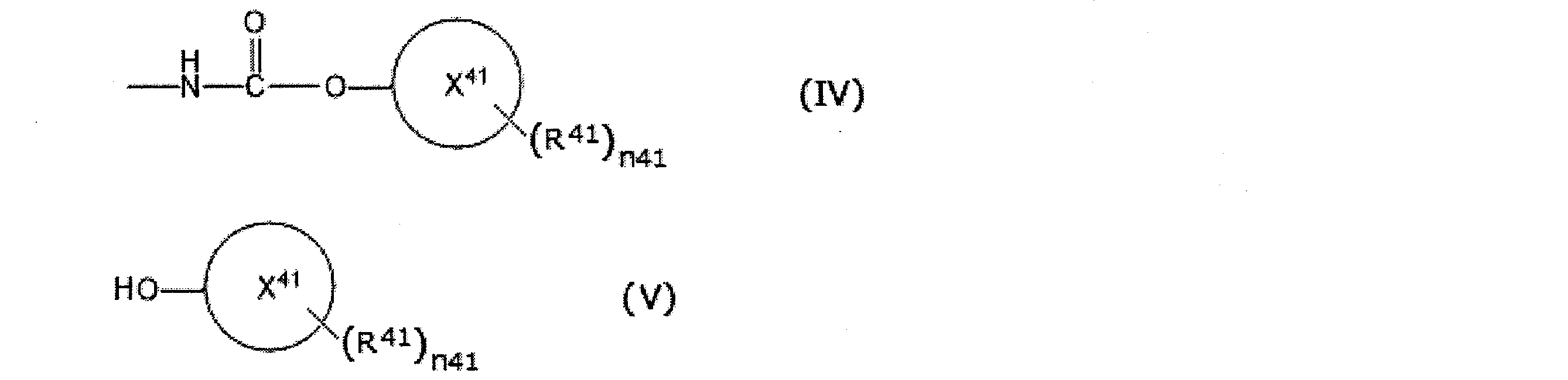
(24)前記工程(7)で回収された前記一般式(V)で表される化合物を、前記一般式(I)で表される化合物の製造工程にリサイクルする、前記(22)または(23)に記載の回収方法。 (23) In the step (7), the content of the metal component is 1000 mass ppm or less and the content of the halogen atom is 1000 mass ppm or less, based on the total mass of the compound represented by the general formula (V) The method according to (22), wherein the compound represented by the general formula (V) is recovered by distillation.
(24) The method according to (22) or (23), wherein the compound represented by the general formula (V) recovered in the step (7) is recycled to the production process of the compound represented by the general formula (I) The recovery method as described in 2.).
具体的には、本明細書中において、IUPAC規則及びこれ以降にも示すIUPACで定められたNomenclature規則(特別に他年度のIUPAC勧告等を引用する場合を除く)を指す場合は、Recommendations 1979に基づいて、1980年に「化学の領域」の別冊として刊行された有機化学と生化学の規則すべてと日本語への字訳規則を包含した版を元にしてその後のすべての改訂及び勧告を加えた「有機化学・生化学命名法」(日本国 南江堂出版 1992年発行の改訂第2版)を引用したものを意味する。 In the present specification, the terms "organic group", "aliphatic", "aromatic" and the like are disclosed in paragraph Nos. [0017] to [0023] of WO 2014/069605 (Reference 1). It is the same as the contents.
Specifically, in the present specification, when referring to the IUPAC rules and the Nomenclature rules defined by IUPAC also shown hereinafter (except when quoting IUPAC recommendations etc. of other fiscal years), Recommendation 1979 Based on the edition that included all the rules of organic chemistry and biochemistry and the rules of transliteration to Japanese, which were published in 1980 as a separate volume of “Area of Chemistry”, and added all subsequent revisions and recommendations. “Organic chemistry / biochemical nomenclature” (revised 2nd edition published in 1992 by Minamiedou Press, Japan).
本実施形態においては、特に説明のない場合、「有機基」及び「置換基」等の用語は、金属原子及び半金属のうち少なくともいずれか1種類を含まない原子で構成される基を意味する。さらに本実施形態では、好ましくは、H(水素原子)、C(炭素原子)、N(窒素原子)、O(酸素原子)、S(硫黄原子)、Cl(塩素原子)、Br(臭素原子)、I(ヨウ素原子)からなる群より選ばれる原子から構成される「有機化合物」、「有機基」又は「置換基」を使用する。 "Organic" refers to the group of compounds in general that are the subject of the nomenclature disclosed in said nomenclature. The subject may be the subject described in the recommendation issued in 1993. However, the “organic” compounds targeted by the above Nomenclature also contain organic metal compounds and metal complexes.
In the present embodiment, unless otherwise stated, terms such as “organic group” and “substituent” mean a group composed of atoms not including at least one of metal atoms and metalloids. . Furthermore, in the present embodiment, preferably, H (hydrogen atom), C (carbon atom), N (nitrogen atom), O (oxygen atom), S (sulfur atom), Cl (chlorine atom), Br (bromine atom) And an "organic compound", an "organic group" or a "substituent" composed of atoms selected from the group consisting of I (iodine atom).
また、本実施形態の説明で用いる「脂肪族化合物」は、飽和及び不飽和、鎖状及び環状のいずれも含有するものであり、上記したH(水素原子);C(炭素原子);N(窒素原子);O(酸素原子);S(硫黄原子);Si(ケイ素原子);Cl(塩素原子)、Br(臭素原子)又はI(ヨウ素原子)のハロゲン原子からなる群より選ばれる原子で構成される「有機化合物」、「有機基」又は「置換基」を指す。 The terms "aliphatic" and "aromatic" are used extensively in the following description. According to the above-mentioned IUPAC rules, it is described that organic compounds are classified into aliphatic compounds and aromatic compounds. Aliphatic compounds are definitions of groups along aliphatic compounds based on the IUPAC recommendations of 1995. In the recommendation, an aliphatic compound is defined as "Acyclic or cyclic, saturated or unsaturated carbon compounds, excluding aromatic compounds".
In addition, the “aliphatic compound” used in the description of the present embodiment contains both saturated and unsaturated, linear and cyclic, and the above-described H (hydrogen atom); C (carbon atom); Nitrogen atom); O (oxygen atom); S (sulfur atom); Si (silicon atom); Cl (chlorine atom), Br (bromine atom) or I (iodine atom) selected from the group consisting of halogen atoms It refers to the "organic compound", "organic group" or "substituent" that is configured.
また、アラルキル基、アルキル基等を包含した非芳香族反応性基を、「芳香族基で置換されていてもよい脂肪族基」、「芳香族基が結合していてもよい脂肪族基」等と表記することがある。 When an aromatic group such as an aralkyl group is bonded to an aliphatic group, such "aliphatic group substituted by an aromatic group" or "a group consisting of an aliphatic group to which an aromatic group is bonded" It may be written. This is based on the reactivity in the present embodiment, and the property relating to the reaction of a group such as an aralkyl group is very similar to the reactivity of aliphatic rather than aromaticity.
In addition, a non-aromatic reactive group including an aralkyl group and an alkyl group may be "an aliphatic group which may be substituted by an aromatic group", "an aliphatic group to which an aromatic group may be bonded" It may be written as etc.
本発明の第1の実施形態の有機アミンの回収方法は、下記一般式(I)で表される化合物(以下、「化合物(I)」と称する場合がある)の製造方法で副生する高沸点化合物を含む液相成分から、下記一般式(III)で表される化合物(以下、「化合物(III)」と称する場合がある)を回収する方法であって、下記工程(1)~工程(4)を含む。
工程(1):前記高沸点化合物を含む液相成分と少なくとも一種の活性水素含有化合物とを反応器内で反応させる工程。
工程(2):前記反応器の気相成分を冷却することにより得られた凝縮液を前記反応器内へ戻す工程。
工程(3):前記工程(2)において、凝縮されなかった気相成分を前記反応器以外へ排出する工程。
工程(4):前記反応器内の液相成分として、前記一般式(III)で表される化合物を含有する反応液を前記反応器外に排出する工程。 «Collection method»
The method for recovering an organic amine according to the first embodiment of the present invention is a method for producing a compound represented by the following general formula (I) (hereinafter sometimes referred to as “compound (I)”) by-product A method of recovering a compound represented by the following general formula (III) (hereinafter sometimes referred to as "compound (III)") from a liquid phase component containing a boiling point compound, which comprises the steps of: (4) is included.
Step (1): a step of reacting the liquid phase component containing the high-boiling point compound with at least one active hydrogen-containing compound in a reactor.
Step (2): returning the condensate obtained by cooling the gas phase components of the reactor into the reactor.
Step (3): A step of discharging the gas phase component not condensed in the step (2) to other than the reactor.
Step (4): discharging the reaction liquid containing the compound represented by the general formula (III) as a liquid phase component in the reactor to the outside of the reactor.
化合物は(I)は、下記一般式(I)で表される化合物であり、少なくとも1つのイソシアネート基を有するイソシアネート化合物である。 <Compound (I)>
The compound (I) is a compound represented by the following general formula (I), and is an isocyanate compound having at least one isocyanate group.
前記一般式(1)中、R11は1価以上3価以下の有機基である。中でも、R11としては、炭素数1以上20以下の1価以上3価以下の脂肪族基又は炭素数6以上20以下の1価以上3価以下の芳香族基が好ましく、炭素数1以上20以下の1価以上3価以下の脂肪族炭化水素基、炭素数6以上20以下の1価以上3価以下の芳香族基、又は、これら脂肪族炭化水素基及び芳香族基のうち少なくとも2つの基がエステル基を介して結合してなる炭素数1以上20以下の基が好ましい。 [R 11 ]
In the general formula (1), R 11 is an organic group having a valence of 1 to 3. Among them, as R 11, preferably a monovalent or trivalent less aromatic group having 1 to 20 20 or less following monovalent or trivalent less aliphatic group or having 6 or more carbon-carbon, 1 to 20 carbon atoms The following monovalent hydrocarbon groups and trivalent or less aliphatic hydrocarbon groups, C6 or more and 20 or less monovalent or trivalent aromatic groups, or at least two of these aliphatic hydrocarbon groups and aromatic groups The group having 1 to 20 carbon atoms formed by bonding of groups via an ester group is preferred.
R11が脂肪族炭化水素基である場合、R11は、直鎖状若しくは分岐鎖状のアルキル基、アルキレン基若しくはアルカントリイル基、シクロアルキル基、シクロアルキレン基若しくはシクロアルカントリイル基、又は、前記アルキル基、前記アルキレン基若しくは前記アルカントリイル基と、前記シクロアルキル基、前記シクロアルキレン基若しくは前記シクロアルカントリイル基とから構成される基が好ましく、直鎖状若しくは分岐鎖状のアルキレン基若しくはアルカントリイル基、シクロアルキレン基若しくはシクロアルカントリイル基、又は、前記アルキレン基若しくは前記アルカントリイル基と、前記シクロアルキル基、前記シクロアルキレン基若しくは前記シクロアルカントリイル基とから構成される基がより好ましい。
直鎖状又は分岐鎖状のアルキレン基としては、例えば、メチレン基、エチレン基、プロピレン基、トリメチレン基、ペンチレン基、n-ヘキシレン基、デカメチレン基等が挙げられる。
シクロアルキレン基としては、例えば、シクロブチレン基、シクロヘキレン基等が挙げられる。
直鎖状又は分岐鎖状アルカントリイル基としては、例えば、ヘキサントリイル基、ノナントリイル基、デカントリイル基等が挙げられる。
シクロアルカントリイル基としては、例えば、シクロプロパントリイル基、シクロブタントリイル基、シクロペンタントリイル基、シクロヘキサントリイル基等が挙げられる。 (R 11 : aliphatic hydrocarbon group)
When R 11 is an aliphatic hydrocarbon group, R 11 is a linear or branched alkyl group, an alkylene group or an alkanetriyl group, a cycloalkyl group, a cycloalkylene group or a cycloalkanetriyl group, or A group composed of the alkyl group, the alkylene group or the alkanetriyl group, and the cycloalkyl group, the cycloalkylene group or the cycloalkanetriyl group, and is preferably a linear or branched alkylene group Group or an alkanetriyl group, a cycloalkylene group or a cycloalkanetriyl group, or the alkylene group or the alkanetriyl group and the cycloalkyl group, the cycloalkylene group or the cycloalkanetriyl group Are more preferred.
Examples of linear or branched alkylene groups include methylene, ethylene, propylene, trimethylene, pentylene, n-hexylene, decamethylene and the like.
As a cycloalkylene group, a cyclobutylene group, a cyclohexene group, etc. are mentioned, for example.
Examples of the linear or branched alkanetriyl group include a hexanetriyl group, a nonantriyl group, a decanetriyl group and the like.
As a cycloalkane triyl group, a cyclopropane triyl group, a cyclobutane triyl group, a cyclopentane triyl group, a cyclohexane triyl group etc. are mentioned, for example.
脂肪族ジイソシアネート類としては、例えば、エチレンジイソシアネート、ジイソシアナトプロパン(各異性体)、ジイソシアナトブタン(各異性体)、ジイソシアナトペンタン(各異性体)、ジイソシアナトヘキサン(各異性体)、ジイソシアナトデカン(各異性体)、イソホロンジイソシアネート(各異性体)、ジシクロヘキシルメタンジイソシアネート(各異性体)等が挙げられる。
脂肪族トリイソシアネート類としては、例えば、トリイソシアナトヘキサン(各異性体)、トリイソシアナトノナン(各異性体)、トリイソシアナトデカン(各異性体)等が挙げられる。
置換された環式脂肪族ポリイソシアネート類としては、例えば、ジイソシアナトシクロブタン(各異性体)、ジイソシアナトシクロヘキサン(各異性体)、3-イソシアナトメチル-3,5,5-トリメチルシクロヘキシルイソシアネート(シス体及びトランス体のうち少なくともいずれかの異性体)、メチレンビス(シクロヘキシルイソシアネート)(各異性体)等が挙げられる。 When R 11 is an aliphatic hydrocarbon group, specific examples of compound (I) include aliphatic diisocyanates, aliphatic triisocyanates, substituted cycloaliphatic polyisocyanates, and the like.
Examples of aliphatic diisocyanates include ethylene diisocyanate, diisocyanatopropane (each isomer), diisocyanatobutane (each isomer), diisocyanatopentane (each isomer), and diisocyanatohexane (each isomer) And diisocyanatodecane (each isomer), isophorone diisocyanate (each isomer), dicyclohexylmethane diisocyanate (each isomer) and the like.
Examples of aliphatic triisocyanates include triisocyanatohexane (each isomer), triisocyanatononane (each isomer), triisocyanatodecane (each isomer) and the like.
As substituted cycloaliphatic polyisocyanates, for example, diisocyanatocyclobutane (each isomer), diisocyanatocyclohexane (each isomer), 3-isocyanatomethyl-3,5,5-trimethylcyclohexyl isocyanate (Cis isomer and / or isomer of at least one of trans isomer), methylene bis (cyclohexyl isocyanate) (each isomer) and the like.
R11が芳香族基である場合、置換基を有してもよい炭素数6以上13以下の芳香環を有する基が好ましい。置換基としては、例えば、アルキル基、アリール基、アラルキル基等が挙げられる。芳香環としては、芳香族炭化水素環であってもよく、複素芳香族環であってもよく、具体的には、例えば、ベンゼン環、ナフタレン環、ピリジン環等が挙げられる。 (R 11 : aromatic group)
When R 11 is an aromatic group, a group having an aromatic ring having 6 to 13 carbon atoms which may have a substituent is preferable. As a substituent, an alkyl group, an aryl group, an aralkyl group etc. are mentioned, for example. The aromatic ring may be an aromatic hydrocarbon ring or a heteroaromatic ring, and specific examples thereof include a benzene ring, a naphthalene ring, and a pyridine ring.
芳香族ジイソシアネート類としては、例えば、ジイソシアナトベンゼン(各異性体)、ジイソシアナトトルエン(各異性体)、メチレンジアニリン(各異性体)、ジイソシアナトメシチレン(各異性体)、ジイソシアナトビフェニル(各異性体)、ジイソシアナトジベンジル(各異性体)、ビス(イソシアナトフェニル)プロパン(各異性体)、ビス(イソシアナトフェニル)エーテル(各異性体)、ビス(イソシアナトフェノキシエタン)(各異性体)、ジイソシアナトキシレン(各異性体)、ジイソシアナトアニソール(各異性体)、ジイソシアナトフェネトール(各異性体)、ジイソシアナトナフタレン(各異性体)、ジイソシアナトメチルベンゼン(各異性体)、ジイソシアナトメチルピリジン(各異性体)、ジイソシアナトメチルナフタレン(各異性体)、ジイソシアナトジフェニルメタン(各異性体)、テトラメチルキシリレンジイソシアネート(各異性体)等が挙げられる。
芳香族トリイソシアネート類としては、例えば、トリイソシアナトベンゼン(各異性体)、トリイソシアナト-メチルベンゼン(各異性体)、トリス(イソシアナトプロパン-イル)ベンゼン(各異性体)、トリス(イソシアナトプロパン-イル)-メチルベンゼン(各異性体)、トリス(イソシアナトメチル)-メチルベンゼン(各異性体)、((イソシアナト-フェニレン)ビス(メチレン))ビス(イソシアネートベンゼン)(各異性体)等が挙げられる。 When R 11 is an aromatic group, specific examples of the compound (I) include aromatic diisocyanates and aromatic triisocyanates.
As aromatic diisocyanates, for example, diisocyanato benzene (each isomer), diisocyanato toluene (each isomer), methylene dianiline (each isomer), diisocyanato mesitylene (each isomer), diisocyanate Natobiphenyl (each isomer), diisocyanato dibenzyl (each isomer), bis (isocyanato phenyl) propane (each isomer), bis (isocyanato phenyl) ether (each isomer), bis (isocyanato phenoxy) Ethane) (each isomer), diisocyanatoxylene (each isomer), diisocyanatoanisole (each isomer), diisocyanatophenetol (each isomer), diisocyanato naphthalene (each isomer), Isocyanato methyl benzene (each isomer), diisocyanato methyl pyridine (each isomer), diisocyanato methyl Futaren (isomers), diisocyanato-diphenylmethane (isomers), tetramethylxylylene diisocyanate (isomers) and the like.
The aromatic triisocyanates include, for example, triisocyanatobenzene (each isomer), triisocyanato-methylbenzene (each isomer), tris (isocyanatopropane-yl) benzene (each isomer), tris (isocyanate) Natopropan-yl) -methylbenzene (each isomer), tris (isocyanatomethyl) -methylbenzene (each isomer), ((isocyanato-phenylene) bis (methylene)) bis (isocyanatobenzene) (each isomer) Etc.
R11が、上記脂肪族炭化水素基及び上記芳香族基のうち少なくとも2つの基がエステル基を介して結合してなる炭素数1以上20以下の基である場合、化合物(I)として具体的には、例えば、アクリル酸-2-イソシアナト-エチルエステル、2-メチル-アクリル酸-2-イソシアナト-エチルエステル、アクリル酸-2-イソシアナト-プロピルエステル、2-メチル-アクリル酸-2-イソシアナト-プロピルエステル、アクリル酸-3-イソシアナト-プロピルエステル、2-メチル-アクリル酸-3-イソシアナト-プロピルエステル、アクリル酸-4-イソシアナト-ブチルエステル、2-メチル-アクリル酸-4-イソシアナト-ブチルエステル、アクリル酸-5-イソシアナト-ペンチルエステル、2-メチル-アクリル酸-5-イソシアナト-ペンチルエステル、アクリル酸-6-イソシアナト-ヘキシルエステル、2-メチル-アクリル酸-6-イソシアナト-ヘキシルエステル、アクリル酸-8-イソシアナト-オクチルエステル、2-メチル-アクリル酸-8-イソシアナト-オクチルエステル、アクリル酸-10-イソシアナト-デシルエステル、2-メチル-アクリル酸-10-イソシアナト-デシルエステル、アクリル酸-11-イソシアナト-ウンデシルエステル、2-メチル-アクリル酸-11-イソシアナト-ウンデシルエステル、アクリル酸-12-イソシアナト-ドデシルエステル、2-メチル-アクリル酸-12-イソシアナト-ドデシルエステル、リジンメチルエステルジイソシアネート、リジンエチルエステルジイソシアネート、2-イソシアナトエチル-2,5-ジイソシアナトペンタノエート、2-イソシアナトエチル-2,6-ジイソシアナトヘキサノエート、ビス(2-イソシアナトエチル)-2-イソシアナトブタンジオエート、ビス(2-イソシアナトエチル)-2-イソシアナトペンタンジオエート、トリス(2-イソシアナトエチル)ヘキサン-1,3,6-トリカルボキシレート等が挙げられる。 (R 11 : a group having 1 to 20 carbon atoms formed by bonding of at least two of the aliphatic hydrocarbon group and the aromatic group via an ester group)
When R 11 is a group having 1 to 20 carbon atoms formed by bonding of at least two of the above aliphatic hydrocarbon group and the above aromatic group via an ester group, specific as Compound (I) For example, acrylic acid-2-isocyanato-ethyl ester, 2-methyl-acrylic acid-2-isocyanato-ethyl ester, acrylic acid-2-isocyanato-propyl ester, 2-methyl-acrylic acid-2-isocyanato- Propyl ester, acrylic acid-3-isocyanato-propyl ester, 2-methyl-acrylic acid-3-isocyanato-propyl ester, acrylic acid-4-isocyanato-butyl ester, 2-methyl-acrylic acid-4-isocyanato-butyl ester , Acrylic acid-5-isocyanato-pentyl ester, 2-methyl-acrylic Acid 5-isocyanato-pentyl ester, acrylic acid-6-isocyanato-hexyl ester, 2-methyl-acrylic acid-6-isocyanato-hexyl ester, acrylic acid-8-isocyanato-octyl ester, 2-methyl-acrylic acid -8-Isocyanato-octyl ester, acrylic acid -10-isocyanato-decyl ester, 2-methyl-acrylic acid -10-isocyanato-decyl ester, acrylic acid-11-isocyanato-undecyl ester, 2-methyl-acrylic acid- 11-isocyanato-undecyl ester, acrylic acid 12-isocyanato-dodecyl ester, 2-methyl-acrylic acid 12-isocyanato-dodecyl ester, lysine methyl ester diisocyanate, lysine ethyl ester diisocyanate , 2-isocyanatoethyl-2,5-diisocyanatopentanoate, 2-isocyanatoethyl-2,6-diisocyanatohexanoate, bis (2-isocyanatoethyl) -2-isocyanatobutanedio And bis (2-isocyanatoethyl) -2-isocyanatopentanedioate, tris (2-isocyanatoethyl) hexane-1,3,6-tricarboxylate and the like.
前記一般式(I)中、n11は、イソシアネート基の数を表し、1以上3以下の整数である。n11は2以上3以下が好ましい。 [N11]
In the general formula (I), n11 represents the number of isocyanate groups and is an integer of 1 or more and 3 or less. n11 is preferably 2 or more and 3 or less.
化合物(III)は、下記一般式(III)で表される化合物であり、少なくとも1つのアミノ基を有するアミノ基含有化合物である。 <Compound (III)>
The compound (III) is a compound represented by the following general formula (III), and is an amino group-containing compound having at least one amino group.
前記一般式(III)中、R31は1価以上3価以下の有機基である。R31としては、上記R11において例示されたものと同様のものが挙げられる。 [R 31 ]
In the general formula (III), R 31 is an organic group having a valence of 1 to 3. Examples of R 31 include the same as those exemplified for R 11 above.
R31が脂肪族炭化水素基である場合、化合物(III)として具体的には、例えば、脂肪族ジアミン類、脂肪族トリアミン類、置換された環式脂肪族ポリアミン類等が挙げられる。
脂肪族ジアミン類としては、例えば、エチレンジアミン、ジアミノプロパン(各異性体)、ジアミノブタン(各異性体)、ジアミノペンタン(各異性体)、ジアミノヘキサン(各異性体)、ジアミノデカン(各異性体)等が挙げられる。
脂肪族トリアミン類としては、例えば、トリアミノヘキサン(各異性体)、トリアミノノナン(各異性体)、トリアミノデカン(各異性体)等が挙げられる。
置換された環式脂肪族ポリアミン類としては、例えば、ジアミノシクロブタン(各異性体)、ジアミノシクロヘキサン(各異性体)、3-アミノメチル-3,5,5-トリメチルシクロヘキシルアミン(シス体及びトランス体のうち少なくともいずれかの異性体)、メチレンビス(シクロヘキシルアミン)(各異性体)等が挙げられる。 (R 31 : aliphatic hydrocarbon group)
When R 31 is an aliphatic hydrocarbon group, specific examples of compound (III) include aliphatic diamines, aliphatic triamines, substituted cycloaliphatic polyamines, and the like.
Examples of aliphatic diamines include ethylenediamine, diaminopropane (each isomer), diaminobutane (each isomer), diaminopentane (each isomer), diaminohexane (each isomer), diaminodecane (each isomer) Etc.
Examples of aliphatic triamines include triaminohexane (each isomer), triaminononane (each isomer), triaminodecane (each isomer) and the like.
As substituted cycloaliphatic polyamines, for example, diaminocyclobutane (each isomer), diaminocyclohexane (each isomer), 3-aminomethyl-3,5,5-trimethylcyclohexylamine (cis and trans) And the like), methylene bis (cyclohexylamine) (each isomer), and the like.
R31が芳香族基である場合、化合物(III)として具体的には、例えば、芳香族ジアミン類、芳香族トリアミン類等が挙げられる。
芳香族ジアミン類としては、例えば、ジアミノベンゼン(各異性体)、ジアミノトルエン(各異性体)、メチレンジアニリン(各異性体)、ジアミノメシチレン(各異性体)、ジアミノビフェニル(各異性体)、ジアミノジベンジル(各異性体)、ビス(アミノフェニル)プロパン(各異性体)、ビス(アミノフェニル)エーテル(各異性体)、ビス(アミノフェノキシエタン)(各異性体)、ジアミノキシレン(各異性体)、ジアミノアニソール(各異性体)、ジアミノフェネトール(各異性体)、ジアミノナフタレン(各異性体)、ジアミノメチルベンゼン(各異性体)、ジアミノメチルピリジン(各異性体)、ジアミノメチルナフタレン(各異性体)、ジアミノジフェニルメタン(各異性体)、テトラメチルキシリレンジアミン(各異性体)等が挙げられる。
芳香族トリアミン類としては、例えば、トリアミノベンゼン(各異性体)、トリアミノメチルベンゼン(各異性体)、トリス(アミノプロパン-イル)ベンゼン(各異性体)、トリス(アミノプロパン-イル)-メチルベンゼン(各異性体)、トリス(アミノメチル)-メチルベンゼン(各異性体)、((アミノフェニレン)ビス(メチレン))ビス(アミンベンゼン)(各異性体)等が挙げられる。 (R 31 : aromatic group)
When R 31 is an aromatic group, specific examples of the compound (III) include aromatic diamines and aromatic triamines.
Examples of the aromatic diamines include diaminobenzene (each isomer), diaminotoluene (each isomer), methylenedianiline (each isomer), diaminomesitylene (each isomer), diaminobiphenyl (each isomer), Diaminodibenzyl (each isomer), bis (aminophenyl) propane (each isomer), bis (aminophenyl) ether (each isomer), bis (aminophenoxyethane) (each isomer), diaminoxylene (each isomer ), Diaminoanisole (each isomer), diaminophenetol (each isomer), diaminonaphthalene (each isomer), diaminomethylbenzene (each isomer), diaminomethylpyridine (each isomer), diaminomethylnaphthalene (each isomer) Each isomer), diaminodiphenylmethane (each isomer), tetramethyl xylylene diamine (each Body), and the like.
Examples of the aromatic triamines include triaminobenzene (each isomer), triaminomethylbenzene (each isomer), tris (aminopropane-yl) benzene (each isomer), tris (aminopropane-yl)- Examples include methylbenzene (each isomer), tris (aminomethyl) -methylbenzene (each isomer), ((aminophenylene) bis (methylene)) bis (aminebenzene) (each isomer), and the like.
R31が上記脂肪族炭化水素基及び上記芳香族基のうち少なくとも2つの基がエステル基を介して結合してなる炭素数1以上20以下の基である場合、化合物(III)として具体的には、例えば、アクリル酸-2-アミノエチルエステル、2-メチル-アクリル酸-2-アミノエチルエステル、アクリル酸-2-アミノプロピルエステル、2-メチル-アクリル酸-2-アミノプロピルエステル、アクリル酸-3-アミノプロピルエステル、2-メチル-アクリル酸-3-アミノプロピルエステル、アクリル酸-4-アミノブチルエステル、2-メチル-アクリル酸-4-アミノブチルエステル、アクリル酸-5-アミノペンチルエステル、2-メチル-アクリル酸-5-アミノペンチルエステル、アクリル酸-6-アミノヘキシルエステル、2-メチル-アクリル酸-6-アミノヘキシルエステル、アクリル酸-8-アミノクチルエステル、2-メチル-アクリル酸-8-アミノクチルエステル、アクリル酸-10-アミノデシルエステル、2-メチル-アクリル酸-10-アミノデシルエステル、アクリル酸-11-アミノンデシルエステル、2-メチル-アクリル酸-11-アミノンデシルエステル、アクリル酸-12-アミノドデシルエステル、2-メチル-アクリル酸-12-アミノドデシルエステル、リジンメチルエステルジアミン、リジンエチルエステルジアミン、2-アミノエチル-2,5-ジアミノペンタノエート、2-アミノエチル-2,6-ジアミノヘキサノエート、ビス(2-アミノエチル)-2-アミノブタンジオエート、ビス(2-アミノエチル)-2-アミノペンタンジオエート、トリス(2-アミノエチル)ヘキサン-1,3,6-トリカルボキシレート等が挙げられる。 (R 31 : A group having 1 to 20 carbon atoms formed by bonding of at least two of the above aliphatic hydrocarbon group and the above aromatic group via an ester group)
When R 31 is a group having 1 to 20 carbon atoms formed by bonding of at least two of the above aliphatic hydrocarbon group and the above aromatic group via an ester group, specifically as Compound (III) For example, acrylic acid 2-aminoethyl ester, 2-methyl-acrylic acid 2-aminoethyl ester, acrylic acid 2-aminopropyl ester, 2-methyl-acrylic acid 2-aminopropyl ester, acrylic acid -3-aminopropyl ester, 2-methyl-acrylic acid 3-aminopropyl ester, acrylic acid 4-aminobutyl ester, 2-methyl-acrylic acid 4-aminobutyl ester, acrylic acid 5-aminopentyl ester , 2-Methyl-acrylic acid 5-aminopentyl ester, acrylic acid 6-aminohexyl ester And 2-methyl-acrylic acid-6-aminohexyl ester, acrylic acid-8-aminocutyl ester, 2-methyl-acrylic acid-8-aminocutyl ester, acrylic acid-10-aminodecyl ester, 2-methyl- Acrylic acid-10-aminodecyl ester, acrylic acid-11-aminon decyl ester, 2- methyl- acrylic acid-11-aminon decyl ester, acrylic acid-12-aminododecyl ester, 2- methyl-acrylic acid-12 amino Dodecyl ester, lysine methyl ester diamine, lysine ethyl ester diamine, 2-aminoethyl-2,5-diaminopentanoate, 2-aminoethyl-2,6-diaminohexanoate, bis (2-aminoethyl) -2 -Aminobutanedioate, bis (2-aminoethyl) 2-amino-pentanedioate, tris (2-aminoethyl) hexane-1,3,6-tri-carboxylate and the like.
前記一般式(III)中、n31は、アミノ基の数を表し、1以上3以下の整数である。n31は2以上3以下が好ましい。 [N31]
In the general formula (III), n31 represents the number of amino groups and is an integer of 1 or more and 3 or less. n31 is preferably 2 or more and 3 or less.
高沸点化合物は、化合物(I)の製造方法で副生する化合物であって、前記化合物(I)の製造工程において、熱分解反応器から気相成分として抜き出される化合物に対して、同条件で気相成分とならなかった化合物であり、その沸点は特に限定されないが、例えば、熱分解反応器の操作圧力において300℃以上である。 <High-boiling compounds>
The high-boiling point compound is a compound by-produced in the method for producing the compound (I), and the same conditions apply to the compound extracted as a gas phase component from the thermal decomposition reactor in the production process of the compound (I). And the boiling point thereof is not particularly limited, and is, for example, 300 ° C. or higher at the operating pressure of the thermal decomposition reactor.
化合物(I)の製造方法は、炭酸誘導体とヒドロキシ化合物と化合物(III)とから製造する方法であることが好ましい。
前記化合物(I)の製造方法で副生する高沸点化合物を含む液相成分は、炭酸誘導体とヒドロキシ化合物と化合物(III)とを反応させて得られるカルバメートを含むカルバメート含有液を、熱分解反応装置に供給して、前記カルバメートと熱分解反応に付し、生成する化合物(I)を含む気相成分を回収する際に、熱分解反応装置から抜き出される液相成分であることが好ましい。 <Method for producing compound (I)>
The method of producing the compound (I) is preferably a method of producing from a carbonic acid derivative, a hydroxy compound and the compound (III).
The liquid phase component containing the high-boiling point compound by-produced by the method for producing the compound (I) is a thermal decomposition reaction of a carbamate-containing liquid containing a carbamate obtained by reacting a carbonic acid derivative, a hydroxy compound and a compound (III). When the gas phase component containing the compound (I) which is supplied to the apparatus and subjected to the thermal decomposition reaction with the carbamate is recovered, it is preferably a liquid phase component extracted from the thermal decomposition reaction apparatus.
炭酸誘導体としては、例えば、尿素、N-無置換カルバミン酸エステル、炭酸エステル等が挙げられる。 [Carbonate derivative]
Examples of the carbonic acid derivative include urea, N-unsubstituted carbamic acid ester, carbonic acid ester and the like.
N-無置換カルバミン酸エステルとしては、例えば、N-無置換カルバミン酸エチエル、N-無置換カルバミン酸ブチル、N-無置換カルバミン酸ヘキシル、N-無置換カルバミン酸オクチル、N-無置換カルバミン酸フェニル等が挙げられる。
なお、「N-無置換」とは、H2N-COOR(Rは、1価の炭化水素基である)であることを指し、窒素原子に結合している1つの水素原子が炭化水素基に置換された構造R’-NH-COOR(R及びR’は、それぞれ独立に1価の炭化水素基である)との違いを明確にするために使用している。 (N-unsubstituted carbamic acid ester)
Examples of the N-substituted carbamic acid ester include N-substituted ethyl carbamate, N-substituted butyl carbamate, N-substituted hexyl carbamate, N-substituted octyl carbamate, and N-substituted carbamic acid And the like.
Note that "N-unsubstituted" refers to H 2 N-COOR (R is a monovalent hydrocarbon group), and one hydrogen atom bonded to a nitrogen atom is a hydrocarbon group Is used to clarify the difference from the structure R′—NH—COOR (wherein R and R ′ each independently represent a monovalent hydrocarbon group).
炭酸エステルとしては、例えば、炭酸ジメチル、炭酸ジエチル、炭酸ジブチル、炭酸ジヘキシル、炭酸ジオクチル、炭酸ジフェニル、炭酸ジ(メチルフェニル)等が挙げられる。 (Carbonate ester)
Examples of the carbonate include dimethyl carbonate, diethyl carbonate, dibutyl carbonate, dihexyl carbonate, dioctyl carbonate, diphenyl carbonate, di (methyl phenyl) carbonate and the like.
ヒドロキシ化合物としては、例えば、アルコール、芳香族ヒドロキシ化合物等が挙げられる。中でも、ヒドロキシ化合物としては、芳香族ヒドロキシ化合物が好ましく用いられる。 [Hydroxy compound]
As a hydroxy compound, alcohol, an aromatic hydroxy compound, etc. are mentioned, for example. Among them, aromatic hydroxy compounds are preferably used as hydroxy compounds.
アルコールとしては、例えば、メタノール、エタノール、プロパノール(各異性体)、ブタノール(各異性体)、ペンタノール(各異性体)、ヘキサノール(各異性体)、ヘプタノール(各異性体)、オクタノール(各異性体)、ノナノール(各異性体)、デカノール(各異性体)、ドデカノール(各異性体)、オクタデカノール(各異性体)、シクロペンタノール、シクロヘキサノール、フェニルメタノール、フェニルエタノール(各異性体)、フェニルプロパノール(各異性体)、フェニルブタノール(各異性体)、フェニルペンタノール(各異性体)、フェニルヘキサノール(各異性体)、フェニルヘプタノール(各異性体)、フェニルオクタノール(各異性体)、フェニルノナノール(各異性体)等が挙げられる。 (alcohol)
Examples of the alcohol include methanol, ethanol, propanol (each isomer), butanol (each isomer), pentanol (each isomer), hexanol (each isomer), heptanol (each isomer), octanol (each isomer) ), Nonanol (each isomer), decanol (each isomer), dodecanol (each isomer), octadecanol (each isomer), cyclopentanol, cyclohexanol, phenylmethanol, phenylethanol (each isomer) , Phenylpropanol (each isomer), phenylbutanol (each isomer), phenylpentanol (each isomer), phenylhexanol (each isomer), phenylheptanol (each isomer), phenyl octanol (each isomer) And phenylnonanol (each isomer) and the like.
芳香族ヒドロキシ化合物としては、例えば、フェノール、メチルフェノール(各異性体)、プロピルフェノール(各異性体)、ブチルフェノール(各異性体)、ペンチルフェノール(各異性体)、オクチルフェノール(各異性体)、ノニルフェノール(各異性体)、フェニルフェノール(各異性体)、フェニルメチルフェノール(各異性体)、フェニルプロピルフェノール(各異性体)、フェノキシフェノール(各異性体)等が挙げられる。 (Aromatic hydroxy compound)
Examples of aromatic hydroxy compounds include phenol, methylphenol (each isomer), propylphenol (each isomer), butylphenol (each isomer), pentylphenol (each isomer), octylphenol (each isomer), nonylphenol (Each isomer), phenylphenol (each isomer), phenylmethylphenol (each isomer), phenylpropylphenol (each isomer), phenoxyphenol (each isomer) and the like.
i)化合物(III)と炭酸誘導体とヒドロキシ化合物とを「同時に」反応させてカルバメートを製造する方法。
ii)炭酸誘導体として尿素及びN-無置換カルバミン酸エステルのうち少なくともいずれかの化合物を用いる方法であって、化合物(III)と炭酸誘導体とを反応させてウレイド基を有する化合物を製造する工程(以下、「工程a)」と称する場合がある)と、得られた該ウレイド基を有する化合物とヒドロキシ化合物とを反応させてカルバメートを製造する工程(以下、「工程b)」と称する場合がある)と、を含む方法。 In the method of producing the compound (I) from the carbonic acid derivative, the hydroxy compound and the compound (III), first, a carbamate is produced from the carbonic acid derivative, the hydroxy compound and the compound (III), and the carbamate is thermally decomposed to obtain a compound ( I) manufacture. Among these, methods for producing carbamate can be roughly classified into the following two methods i) to ii). In the production method of the present embodiment, the following method i) and the following method ii) may be used in combination.
i) A method of producing a carbamate by “simultaneously” reacting compound (III), a carbonic acid derivative and a hydroxy compound.
ii) A method of using a compound of at least one of urea and N-unsubstituted carbamic acid ester as a carbonic acid derivative, which comprises reacting a compound (III) with a carbonic acid derivative to produce a compound having a ureido group ( Hereinafter, the step of producing a carbamate by reacting the obtained compound having a ureido group with a hydroxy compound, which may be referred to as “step a)”, may be referred to as “step b)”. And how to contain.
上記方法i)において、ヒドロキシ化合物の量は、使用される化合物(III)のアミノ基に対して化学量論比(モル比)で、1倍以上500倍以下の範囲とすることができる。
炭酸誘導体の量は、使用される化合物(III)のアミノ基に対して化学量論比(モル比)で1倍以上100倍以下の範囲とすることができる。
反応温度は、100℃以上350℃以下の範囲とすることができる。
反応圧力は、0.01kPa以上10MPa以下(絶対圧)の範囲とすることができる。
炭酸誘導体として尿素及びN-無置換カルバミン酸エステルのうち少なくともいずれかの化合物を用いる場合、カルバメートの収率を高めるためには、可能な限り、副生されるアンモニアを系外に除去しながら反応を行う必要がある。アンモニアを系外に除去する方法としては、例えば、反応蒸留法、不活性ガスにより置換する方法、膜分離による方法、吸着分離による方法等が挙げられる。該反応において必要な場合は、溶媒や触媒を使用することができる。
反応時間(連続反応の場合は滞留時間)は、0.01時間以上100時間以下で実施され、反応時間は、方法i)の目的化合物であるカルバメートの生成量によって決定することもできる。 [Method i)]
In the above method i), the amount of the hydroxy compound can be in the range of 1 to 500 times the stoichiometric ratio (molar ratio) to the amino group of the compound (III) to be used.
The amount of the carbonic acid derivative can be in the range of 1 to 100 times the stoichiometric ratio (molar ratio) to the amino group of the compound (III) to be used.
The reaction temperature can be in the range of 100 ° C. or more and 350 ° C. or less.
The reaction pressure can be in the range of 0.01 kPa or more and 10 MPa or less (absolute pressure).
When a compound of at least one of urea and N-unsubstituted carbamic acid ester is used as the carbonic acid derivative, the reaction is carried out while removing by-produced ammonia out of the system as much as possible in order to increase the yield of carbamate. Need to do. Examples of the method of removing ammonia out of the system include a reactive distillation method, a method of substituting with an inert gas, a method of membrane separation, a method of adsorption separation, and the like. If necessary in the reaction, a solvent or a catalyst can be used.
The reaction time (retention time in the case of continuous reaction) is carried out at 0.01 hours to 100 hours, and the reaction time can also be determined by the amount of carbamate produced, which is the target compound of method i).
(工程a))
上記方法ii)において、工程a)は、化合物(III)と炭酸誘導体とを反応させて、ウレイド基を有する化合物を含む反応混合物を得る工程である。工程a)において、炭酸誘導体の量は、使用される化合物(III)のアミノ基に対して化学量論比(モル比)で1倍以上100倍以下の範囲とすることができる。
反応温度は、30℃以上250℃以下の範囲とすることができる。
反応圧力は、0.01kPa以上10MPa以下(絶対圧)の範囲とすることができる。
反応時間(連続法の場合は滞留時間)は、0.001時間以上100時間以下とすることができ、ウレイド基を有する化合物が所望量生成していることを確認して反応を終了することもできる。工程a)において必要な場合は、触媒や溶媒を用いることができる。中でも、続く工程b)で使用するヒドロキシ化合物を溶媒として使用することが好ましい。 [Method ii)]
(Step a))
In the above method ii), step a) is a step of reacting compound (III) with a carbonic acid derivative to obtain a reaction mixture containing a compound having a ureido group. In step a), the amount of the carbonic acid derivative can be in the range of 1 to 100 times the stoichiometric ratio (molar ratio) to the amino group of the compound (III) to be used.
The reaction temperature can be in the range of 30 ° C. or more and 250 ° C. or less.
The reaction pressure can be in the range of 0.01 kPa or more and 10 MPa or less (absolute pressure).
The reaction time (in the case of the continuous method, the residence time) can be 0.001 hours or more and 100 hours or less, and it may be confirmed that the desired amount of a compound having a ureido group is generated to complete the reaction. it can. If necessary in step a), catalysts and solvents can be used. Among them, it is preferable to use the hydroxy compound used in the subsequent step b) as a solvent.
上記方法ii)において、工程b)は、前記工程a)で得られたウレイド基を有する化合物と、ヒドロキシ化合物とを反応させて、カルバメートを製造する工程である。工程a)で反応溶媒としてヒドロキシ化合物を使用した場合は、工程a)で得られる反応液を使用して、そのまま工程b)を行うことができる。
ヒドロキシ化合物の使用量は、使用するウレイド基を有する化合物のウレイド基に対して化学量論比(モル比)で1倍以上500倍以下の範囲とすることができる。
反応温度は、100℃以上350℃以下の範囲とすることができる。
反応圧力は、0.01kPa以上10MPa以下(絶対圧)の範囲とすることができる。
カルバメートの収率を高めるためには、可能な限り、副生されるアンモニアを系外に除去しながら反応を行う必要がある。アンモニアを系外に除去する方法としては、上記「[方法i)]」において例示された方法と同様の方法が挙げられる。
工程b)において必要な場合は、溶媒や触媒を使用することができる。
反応時間(連続反応の場合は滞留時間)は、0.01時間以上100時間以下とすることができ、工程b)の目的化合物であるカルバメートの生成量によって決定することもできる。 (Step b))
In the method ii), the step b) is a step of reacting the compound having a ureido group obtained in the step a) with a hydroxy compound to produce a carbamate. When a hydroxy compound is used as the reaction solvent in step a), step b) can be carried out as it is using the reaction solution obtained in step a).
The amount of the hydroxy compound used can be in the range of 1 to 500 times the stoichiometric ratio (molar ratio) of the ureide group of the compound having a ureido group to be used.
The reaction temperature can be in the range of 100 ° C. or more and 350 ° C. or less.
The reaction pressure can be in the range of 0.01 kPa or more and 10 MPa or less (absolute pressure).
In order to increase the yield of carbamate, it is necessary to carry out the reaction while removing by-produced ammonia out of the system as much as possible. As a method of removing ammonia out of the system, the same method as the method exemplified in the above-mentioned "[Method i)]" can be mentioned.
If necessary in step b), solvents or catalysts can be used.
The reaction time (in the case of continuous reaction, residence time) can be 0.01 hours or more and 100 hours or less, and can also be determined by the amount of carbamate produced as the target compound in step b).
R121としては、化合物(I)のR11において例示されたものと同様のものが挙げられる。
R122は上記ヒドロキシ化合物のヒドロキシ基を除いた基である。すなわち、R122は、1価の脂肪族基又は芳香族基であり、炭素数1以上20以下の直鎖状、分岐鎖状若しくは環状のアルキル基、炭素数6以上13以下のアリール基、又は、炭素数7以上20以下のアラルキル基が好ましい。
炭素数1以上20以下の直鎖状又は分岐鎖状のアルキル基としては、例えば、メチル基、エチル基、プロピル基、ブチル基、ペンチル基、ヘプチル基、オクチル基、ノニル基、デシル基、ドデシル基、オクタデシル基等が挙げられる。
炭素数1以上20以下の環状のアルキル基としては、例えば、シクロペンチル基、シクロヘキシル基等が挙げられる。
炭素数6以上13以下のアリール基としては、例えば、フェニル基、トリル基、エチルフェニル基、プロピルフェニル基、ブチルフェニル基、ペンチルフェニル基、オクチルフェニル基、ノニルフェニル基、ビフェニル基、フェニルエチルフェニル基、フェニルプロピルフェニル基、フェノキシフェニル基等が挙げられる。
炭素数7以上20以下のアラルキル基としては、例えば、ベンジル基、フェニルメチル基、フェニルプロピル基、フェニルブチル基、フェニルペンチル基、フェニルヘキシル基、フェニルへプチル基、フェニルオクチル基、フェニルノニル基等が挙げられる。 In the general formula (XII), R 121 is a monovalent or more and trivalent or less organic group. R 122 is a monovalent organic group. n121 is an integer of 1 or more and 3 or less.
Examples of R 121 include the same as those exemplified for R 11 of compound (I).
R 122 is a group from which the hydroxy group of the above hydroxy compound is removed. That is, R 122 is a monovalent aliphatic group or aromatic group, and is a linear, branched or cyclic alkyl group having 1 to 20 carbon atoms, an aryl group having 6 to 13 carbon atoms, or And an aralkyl group having 7 to 20 carbon atoms is preferable.
As a linear or branched alkyl group having 1 to 20 carbon atoms, for example, methyl group, ethyl group, propyl group, butyl group, pentyl group, heptyl group, octyl group, nonyl group, decyl group, dodecyl group And octadecyl groups.
Examples of the cyclic alkyl group having 1 to 20 carbon atoms include a cyclopentyl group and a cyclohexyl group.
As an aryl group having 6 to 13 carbon atoms, for example, phenyl group, tolyl group, ethylphenyl group, propylphenyl group, butylphenyl group, pentylphenyl group, octylphenyl group, nonylphenyl group, biphenyl group, phenylethylphenyl Groups, phenylpropylphenyl group, phenoxyphenyl group and the like.
The aralkyl group having 7 to 20 carbon atoms is, for example, benzyl group, phenylmethyl group, phenylpropyl group, phenylbutyl group, phenylpentyl group, phenylhexyl group, phenylheptyl group, phenyloctyl group, phenylnonyl group, etc. Can be mentioned.
反応圧力は、通常10Pa以上1×10⁶Pa以下(絶対圧)の範囲で行うことができる。
触媒は必ずしも必要ではなく、触媒を使用しないことが好ましいが、反応温度を低下させたり、反応を早期に完結させるために、触媒を使用してもよい。該触媒としては、カルバメートの質量に対して0.01質量%以上30質量%以下の範囲で用いることができ、具体的には、例えば、有機スズ化合物、銅族金属の化合物、亜鉛化合物、鉄族金属の化合物等が挙げられる。
方法i)及び方法ii)において、カルバメート含有液に含まれるヒドロキシ化合物等を溶媒として用いることができる。
反応時間(連続法の場合は滞留時間)は、目的の反応の進行を妨げない範囲で可能な限り短時間であることが好ましい。 The reaction temperature for thermal decomposition of carbamate can be in the range of 100 ° C. or more and 350 ° C. or less.
The reaction pressure can be usually in the range of 10 Pa or more and 1 × 10 6 Pa or less (absolute pressure).
A catalyst is not always necessary, and it is preferable not to use a catalyst, but a catalyst may be used to lower the reaction temperature or complete the reaction early. The catalyst can be used in the range of 0.01% by mass to 30% by mass with respect to the mass of carbamate. Specifically, for example, organic tin compounds, compounds of copper group metals, zinc compounds, iron And compounds of group metals.
In the method i) and the method ii), a hydroxy compound or the like contained in the carbamate-containing liquid can be used as a solvent.
The reaction time (in the case of the continuous method, the residence time) is preferably as short as possible within the range that does not hinder the progress of the desired reaction.
ここでいう「気相成分」とは、熱分解反応装置内の気相に存在する成分を意味し、該気相成分は、反応目的物である化合物(I)を含み、原料として使用したヒドロキシ化合物の一部又は全部を含んでもよい。
また、「液相成分」とは、熱分解反応装置内の液相に存在する成分を意味し、該液相成分は、高沸点化合物として、下記式(II-1)で表される基(以下、「基(II-1)」と称する場合がある)及び下記式(II-2)で表される基(以下、「基(II-2)」と称する場合がある)の少なくとも1種を有する化合物を含むことが好ましい。 Specifically, the carbamate thermal decomposition reaction is a compound formed by continuously supplying a mixture containing carbamate to a reaction apparatus (sometimes referred to as a thermal decomposition reaction apparatus) and subjecting it to a thermal decomposition reaction. A method is employed in which (I) and part of the hydroxy compound are continuously withdrawn from the thermal decomposition reactor as a gas phase component, and the remainder is continuously withdrawn from the thermal decomposition reactor as a liquid phase component.
The "gas phase component" as used herein means a component present in the gas phase in the thermal decomposition reaction apparatus, and the gas phase component contains the compound (I) which is the reaction object, and is used as a raw material It may contain part or all of the compound.
In addition, “liquid phase component” means a component present in the liquid phase in the thermal decomposition reaction apparatus, and the liquid phase component is a group represented by the following formula (II-1) as a high boiling point compound ( Hereinafter, at least one of “group (II-1)” may be mentioned and at least one group represented by the following formula (II-2) (hereinafter, may be referred to as “group (II-2)”) It is preferable to contain the compound which has these.
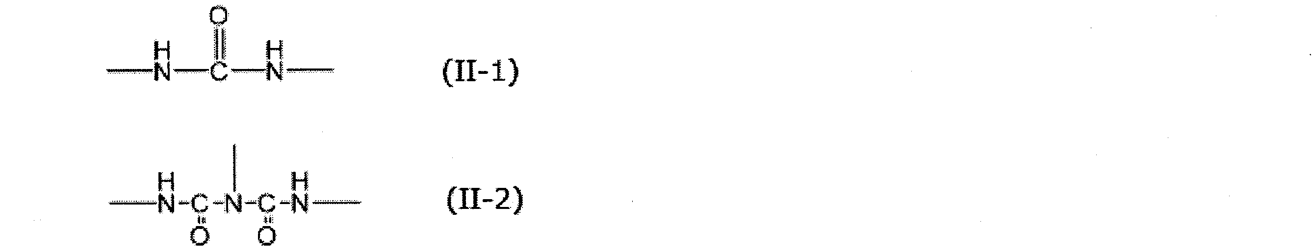

R131及びR134としては、上記R122において例示されたものと同様のものが挙げられる。また、R131及びR134はそれぞれ同一であってもよく、異なっていてもよい。
R132及びR133としては、化合物(I)のR11において例示された2価又は3価の基と同様のもの、例えば、炭素数1~20程度のアルキレン基、炭素数5~20程度のシクロアルキレン基、炭素数6~20程度のアリーレン基等が挙げられる。また、R132及びR133はそれぞれ同一であってもよく、異なっていてもよい。 In the general formula (XIII), R 131 and R 134 are each independently a monovalent organic group. R 132 and R 133 are each independently a divalent or trivalent organic group. n131 and n132 are each independently an integer of 0 or more and 2 or less.
As R 131 and R 134, the same as those exemplified for R 122 above can be mentioned. Further, R 131 and R 134 may be identical to or different from each other.
R 132 and R 133 are the same as the divalent or trivalent groups exemplified for R 11 of compound (I), for example, an alkylene group having about 1 to 20 carbon atoms, about 5 to 20 carbon atoms Examples thereof include cycloalkylene groups and arylene groups having about 6 to 20 carbon atoms. R 132 and R 133 may be identical to or different from each other.

R141、R144及びR146としては、上記R122において例示されたものと同様のものが挙げられる。また、R141、R144及びR146はそれぞれ同一であってもよく、異なっていてもよい。
R142、R143及びR145としては、化合物(I)のR11において例示された2価又は3価の基と同様のもの、例えば、炭素数1~20程度のアルキレン基、炭素数5~20程度のシクロアルキレン基、炭素数6~20程度のアリーレン基等が挙げられる。また、R142、R143及びR145はそれぞれ同一であってもよく、異なっていてもよい。 In the general formula (XIV), each of R 141 , R 144 and R 146 is independently a monovalent organic group. R 142 , R 143 and R 145 are each independently a divalent or trivalent organic group. n141, n142 and n143 are each independently an integer of 0 or more and 2 or less.
Examples of R 141 , R 144 and R 146 include the same as those exemplified for R 122 above. Further, R 141 , R 144 and R 146 may be identical to or different from each other.
R 142 , R 143 and R 145 are the same as the divalent or trivalent groups exemplified for R 11 of the compound (I), for example, an alkylene group having about 1 to 20 carbon atoms, 5 to carbon atoms Examples thereof include about 20 cycloalkylene groups and arylene groups having about 6 to 20 carbon atoms. Further, R 142 , R 143 and R 145 may be identical to or different from each other.
アロファネート基を有する化合物としては、例えば、下記一般式(XV)で表される化合物(以下、「化合物(XV)」と称する場合がある)等が挙げられる。 The liquid phase component may further contain a compound having an allophanate group and / or a compound having an isocyanurate group as the high boiling point compound.
Examples of the compound having an allophanate group include a compound represented by the following general formula (XV) (hereinafter sometimes referred to as “compound (XV)”) and the like.

R151、R153及びR155としては、上記R122において例示されたものと同様のものが挙げられる。また、R151、R153及びR155はそれぞれ同一であってもよく、異なっていてもよい。
R152及びR154としては、化合物(I)のR11において例示された2価又は3価の基と同様のもの、例えば、炭素数1~20程度のアルキレン基、炭素数5~20程度のシクロアルキレン基、炭素数6~20程度のアリーレン基等が挙げられる。また、R152及びR154はそれぞれ同一であってもよく、異なっていてもよい。 In formula (XV), R 151 , R 153 and R 155 each independently represent a monovalent organic group. R 152 and R 154 are each independently a divalent or trivalent organic group. n151 and n152 are each independently an integer of 0 or more and 2 or less.
Examples of R 151 , R 153 and R 155 include the same as those exemplified for R 122 above. R 151 , R 153 and R 155 may be identical to or different from each other.
R 152 and R 154 are the same as the divalent or trivalent groups exemplified for R 11 of the compound (I), for example, an alkylene group having about 1 to 20 carbon atoms, about 5 to 20 carbon atoms Examples thereof include cycloalkylene groups and arylene groups having about 6 to 20 carbon atoms. R 152 and R 154 may be identical to or different from each other.
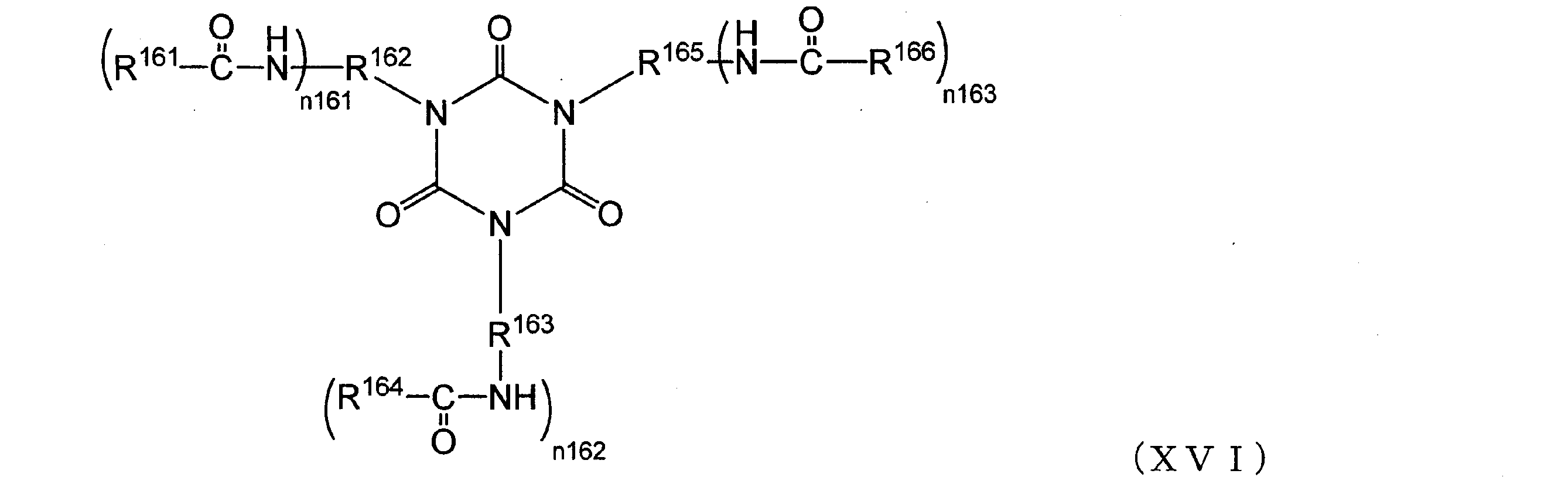
R161、R164及びR166としては、上記R122において例示されたものと同様のものが挙げられる。また、R161、R164及びR166はそれぞれ同一であってもよく、異なっていてもよい。
R162、R163及びR165としては、化合物(I)のR11において例示された2価又は3価の基と同様のもの、例えば、炭素数1~20程度のアルキレン基、炭素数5~20程度のシクロアルキレン基、炭素数6~20程度のアリーレン基等が挙げられる。また、R162、R163及びR165はそれぞれ同一であってもよく、異なっていてもよい。 In formula (XVI), each of R 161 , R 164 and R 166 is independently a monovalent organic group. R 162 , R 163 and R 165 are each independently a divalent or trivalent organic group. n161, n162 and n163 are each independently an integer of 0 or more and 2 or less.
As R 161 , R 164 and R 166, the same as those exemplified for R 122 above can be mentioned. Moreover, R 161 , R 164 and R 166 may be identical to or different from each other.
As R 162 , R 163 and R 165 , the same divalent or trivalent groups as exemplified for R 11 of compound (I), for example, an alkylene group having about 1 to 20 carbon atoms, 5 to 6 carbon atoms Examples thereof include about 20 cycloalkylene groups and arylene groups having about 6 to 20 carbon atoms. Moreover, R 162 , R 163 and R 165 may be identical to or different from each other.
中でも、熱分解反応装置としては、生成する低沸点成分を気相に速やかに移動させられる気-液接触面積の大きな構造が好ましく、管状薄膜蒸発器、管状流下膜蒸発器等の管型反応器を含む反応装置を用いることがより好ましい。上記したように、該熱分解反応装置から化合物(I)を含む気相成分を回収する観点から、前記熱分解反応装置が、上記した管型反応器と、前記気相成分及び前記液相成分を分離する分離槽からなることがさらに好ましい。 The thermal decomposition reaction apparatus is not particularly limited, and, for example, a distillation column, a multistage distillation column, a multitubular reactor, a continuous multistage distillation column, a packed column, a thin film evaporator, a reactor provided with a support inside, Reactors may be used, including forced circulation reactors, drop evaporators, drop evaporators, and the like.
Among them, as the thermal decomposition reaction apparatus, a structure having a large gas-liquid contact area capable of rapidly transferring the low boiling point component to be generated to the gas phase is preferable, and a tubular reactor such as a tubular thin film evaporator or a tubular falling film evaporator It is more preferable to use a reactor containing As described above, from the viewpoint of recovering the gas phase component containing the compound (I) from the thermal decomposition reaction device, the thermal decomposition reaction device comprises the above-mentioned tubular reactor, the gas phase component and the liquid phase component It is further preferable to comprise a separation tank for separating
ここでいう「浸辺長」とは、流体の流れ方向に対して垂直方向の、流体が接触している反応器の壁の周囲の長さ(反応器が円筒形である場合は反応器の断面円周の長さ)を指す。「単位浸辺長流量」は、流体の単位時間流量(kg/時)を浸辺長(m)で除することにより算出することができる。
また、該反応器において液流量が変化する場合は、その最小流量に対する単位浸辺長流量が上記範囲となることが好ましい。 At that time, from the viewpoint of maintaining the wettability of the reactor wall surface and preventing the formation of deposits on the reactor wall surface, the unit immersion side flow rate in the tubular reactor is 10 kg / hour · m · m to 1000 kg / hour · m or less is preferable, 20 kg / hour · m or more and 500 kg / hour · m or less is more preferable, and 50 kg / hour · m or more and 300 kg / hour · m or less is more preferable.
The term "immersed side length" as used herein means the length of the perimeter of the wall of the reactor in contact with the fluid in the direction perpendicular to the flow direction of the fluid (if the reactor is cylindrical, the reactor Point of the circumference of the cross section). The “unit immersion side length flow rate” can be calculated by dividing the unit time flow rate (kg / hour) of the fluid by the immersion side length (m).
When the liquid flow rate changes in the reactor, it is preferable that the unit immersion side flow rate with respect to the minimum flow rate be in the above range.
線速度は、該分離槽を通過する気相成分の体積速度(m3/秒)を、該分離槽の断面積(m2)で除することにより決定される。 In addition, when the liquid phase component is entrained in the gas phase component when separating the gas phase component containing the compound (I), the liquid phase component adheres to the pipe etc. which recovers the gas phase component, causing clogging of the pipe From the viewpoint of suppressing further, the linear velocity of the gas phase component in the separation tank is preferably 10 m / sec or less, more preferably 7 m / sec or less, and still more preferably 3 m / sec or less.
The linear velocity is determined by dividing the volumetric velocity (m 3 / s) of the gas phase component passing through the separation vessel by the cross-sectional area (m 2 ) of the separation vessel.
また、上記した副生成物を溶解し液相状態を保持する観点から、上記液相成分は、上記基(II-1)及び基(II-2)のうち少なくともいずれか1種類の基を有する化合物に加えて、ヒドロキシ化合物を含有することが好ましく、前記ヒドロキシ化合物を、該液相成分の総質量に対して、20質量%以上70質量%以下含有することが好ましく、30質量%以上50質量%以下含有することがより好ましい。ヒドロキシ化合物を上記した量含有させるために、熱分解反応装置からの液相成分を回収する配管及び熱分解反応装置の分離槽のうち少なくともいずれかにヒドロキシ化合物を供給する配管を設けてヒドロキシ化合物を加えることができる。 When the liquid phase component is transferred from the thermal decomposition reactor to the reactor for performing the reaction of step 1) in the recovery method of the present embodiment, it is preferable to transfer the liquid phase component while maintaining it in the liquid state . For that purpose, the liquid phase component is supplied to the reactor where the step 1) is performed in a state of preferably maintained at 150 ° C. or more and 350 ° C. or less, more preferably 200 ° C. or more and 260 ° C. or less.
Further, from the viewpoint of dissolving the above-mentioned by-products and maintaining the liquid phase state, the liquid phase component has at least one of the group (II-1) and the group (II-2). In addition to the compound, a hydroxy compound is preferably contained, and the hydroxy compound is preferably contained in an amount of 20% by mass to 70% by mass with respect to the total mass of the liquid phase component, and is 30% by mass to 50% by mass. It is more preferable to contain% or less. In order to incorporate the hydroxy compound in the above-mentioned amount, the hydroxy compound is provided by providing the piping for supplying the hydroxy compound to at least one of the piping for recovering the liquid phase component from the thermal decomposition reactor and the separation tank of the thermal decomposition reactor. It can be added.
次いで、本実施形態の回収方法の各工程について、以下に詳細を説明する。 <Steps of recovery method>
Next, each step of the recovery method of the present embodiment will be described in detail below.
工程(1)は、上記化合物(I)の製造方法で副生する高沸点化合物を含む液相成分と少なくとも一種の活性水素含有化合物とを反応器内で反応させる工程である。 [Step (1)]
The step (1) is a step of reacting a liquid phase component containing a high boiling point compound by-produced by the method for producing the compound (I) and at least one active hydrogen-containing compound in a reactor.
ビウレット基、アロファネート基、イソシアヌレート基、カルバメート基、ウレア基及びフリース転位末端の含有量は、該液相成分を試料として、例えば、赤外分光測定(IR測定)、核磁気共鳴スペクトル測定(NMR測定)によって定量することができる。
簡易的には、NMR測定によって、上記例示された基のN原子に隣接する-CH2-基(メチレン基)を定量し、この値から上記例示された基の総量を見積もることができる。 The amount of the active hydrogen-containing compound is a stoichiometric ratio relative to the total molar amount of biuret group, allophanate group, isocyanurate group, carbamate group, urea group and Fries rearrangement terminal contained in the liquid phase component, It can be in the range of 1 to 500 times.
The contents of biuret group, allophanate group, isocyanurate group, carbamate group, urea group and fleece rearrangement terminal are measured by, for example, infrared spectroscopy (IR measurement), nuclear magnetic resonance spectroscopy (NMR) using the liquid phase component as a sample Measurement).
Briefly, the —CH 2 — group (methylene group) adjacent to the N atom of the group exemplified above is quantified by NMR measurement, and the total amount of the group exemplified above can be estimated from this value.
圧力は、使用する化合物にもよるが、0.01kPa以上15MPa以下(絶対圧)の範囲であり、減圧でも常圧でも加圧でも実施できる。
上記好ましい温度範囲、使用する活性水素含有化合物、及び、該分解反応で生成する化合物等を勘案すると、加圧での実施が好ましく、0.101MPa以上15MPa以下(絶対圧)の範囲がより好ましく、0.5MPa以上13MPa以下(絶対圧)の範囲がさらに好ましく、2MPa以上8MPa以下(絶対圧)の範囲が特に好ましい。
反応時間(連続反応の場合は滞留時間)は、0.01時間以上100時間以下で実施され、反応液を適宜サンプリングして、目的化合物である化合物(III)の生成量を測定し、所望の生成量に達する時間を反応時間とすることができる。 The temperature at which the decomposition reaction is carried out can be set according to the compound to be used, preferably in the range of 100 ° C. to 350 ° C., more preferably 150 ° C. to 330 ° C., more preferably 200 ° C. to 300 ° C. Is more preferred.
The pressure, which depends on the compound used, is in the range of 0.01 kPa to 15 MPa (absolute pressure), and may be carried out under reduced pressure, normal pressure or increased pressure.
In view of the above preferable temperature range, the active hydrogen-containing compound to be used, and the compound generated by the decomposition reaction, the implementation under pressure is preferable, and the range of 0.101 MPa or more and 15 MPa or less (absolute pressure) is more preferable, The range of 0.5 MPa to 13 MPa (absolute pressure) is more preferable, and the range of 2 MPa to 8 MPa (absolute pressure) is particularly preferable.
The reaction time (retention time in the case of continuous reaction) is carried out at 0.01 hours to 100 hours, and the reaction solution is appropriately sampled to measure the amount of compound (III) which is the target compound, and the desired amount is obtained. The time to reach the production amount can be the reaction time.
工程(2)は、上記工程(1)で副生する気相成分を冷却することにより得られた凝縮液を、前記反応器内へ戻す工程である。
上記工程(1)の分解反応において副生する気相成分は、工程(1)における原料物質である、化合物(I)の製造方法で副生する液相成分や活性水素含有化合物に比べて低沸点である成分であって、例えば、沸点が30℃以下の成分をいう。副生する気相成分は使用する活性水素含有化合物に依存し、具体的には、前記活性水素含有化合物が水を含む場合は二酸化炭素を含み、前記活性水素化合物が尿素を含む場合は二酸化炭素及びアンモニアを含む。
該気相成分によって反応系の圧力が上昇したり、該分解反応が遅くなったりする場合があるため、気相成分の少なくとも一部を反応系外に抜き出しながら上記工程(1)における分解反応を行う。反応系の圧力を一定範囲に保持する、分解反応を速やかに進行させるといった観点から、気相成分は連続的に抜き出すことが好ましい。気相成分を反応器から抜き出す際には、活性水素含有化合物が気相成分とともに反応器外に抜き出されないようにしたり、圧力を調整する保圧弁を設けて反応器内の圧力を調整することが好ましい。
該反応器から抜き出された気相成分は、該反応器に連結された凝縮器に導入されて冷却される。凝縮器内での冷却により得られた凝縮液が該反応器内へ戻される。該凝縮液は、水であることが好ましい。該凝縮器での冷却は0~80℃程度で行われることが好ましい。 [Step (2)]
The step (2) is a step of returning the condensate obtained by cooling the gas phase component by-produced in the step (1) into the reactor.
The gas phase component by-produced in the decomposition reaction of the above step (1) is lower than that of the liquid phase component and the active hydrogen-containing compound by-produced by the method for producing compound (I), which are raw materials in step (1). It is a component which is a boiling point, for example, a component whose boiling point is 30 ° C. or less. The gas phase component by-produced depends on the active hydrogen-containing compound to be used, and specifically, if the active hydrogen-containing compound contains water, it contains carbon dioxide, and if the active hydrogen compound contains urea, carbon dioxide And ammonia.
Since the pressure of the reaction system may increase or the decomposition reaction may be delayed due to the gas phase component, the decomposition reaction in the step (1) may be performed while extracting at least a part of the gas phase component out of the reaction system. Do. From the viewpoint of maintaining the pressure of the reaction system in a certain range and rapidly advancing the decomposition reaction, it is preferable to continuously extract the gas phase component. When extracting the gas phase component from the reactor, make sure that the active hydrogen-containing compound is not extracted out of the reactor together with the gas phase component, or provide a pressure holding valve to adjust the pressure to adjust the pressure in the reactor. Is preferred.
Gas phase components withdrawn from the reactor are introduced into a condenser connected to the reactor and cooled. The condensate obtained by cooling in the condenser is returned to the reactor. The condensate is preferably water. The cooling in the condenser is preferably performed at about 0 to 80.degree.
工程(3)は、上記工程(2)において凝縮されない気相成分を、反応器以外に排出する工程である。凝縮されない気相成分は使用する活性水素含有化合物に依存する。具体的には、前記活性水素含有化合物の少なくとも1種が水である場合は、凝縮されない気相成分は二酸化炭素を含み、前記活性水素化合物の少なくとも1種が尿素である場合は、凝縮されない気相成分は二酸化炭素及びアンモニアを含む。 [Step (3)]
The step (3) is a step of discharging the gas phase component not condensed in the above step (2) to other than the reactor. The gas phase components which are not condensed depend on the active hydrogen-containing compound used. Specifically, when at least one of the active hydrogen-containing compounds is water, the non-condensed gas phase component contains carbon dioxide, and when at least one of the active hydrogen compounds is urea, it is not condensed. Phase components include carbon dioxide and ammonia.
工程(4)は、上記工程(1)における分解反応により生じた液相成分を前記反応器外に排出する工程である。排出される液相成分(反応液)には、化合物(III)が含まれる。 [Step (4)]
Step (4) is a step of discharging the liquid phase component generated by the decomposition reaction in step (1) to the outside of the reactor. The liquid phase component (reaction liquid) to be discharged contains the compound (III).
工程(1)で用いられる反応器は特に制限がなく、公知の反応器が使用できる。例えば、攪拌槽、貯槽、塔型反応器、蒸留塔、充填塔、薄膜蒸発機、強制的運搬装置を備えたパドル型乾燥器、脱ガス機能を備えた押出機、強制的運搬装置を備えた薄膜蒸発機、チューブ状反応器等、反応方法や条件に応じて、従来公知の反応器を適宜組み合わせて使用できる。
また、反応は、バッチ式でもあってもよく、連続流通式であってもよく、それぞれの反応形式に合わせて反応装置を選択すればよい。
反応器の材質にも特に制限はなく、公知の材質が使用できる。例えば、ガラス製、ステンレス製、炭素鋼製、ハステロイ製、基材にグラスライニングを施したもの、テフロン(登録商標)コーティングを行ったもの等を使用できる。SUS304やSUS316、SUS316L等が安価でもあり、好ましく使用できる。反応器は、必要に応じて、さらに、流量計、温度計等の計装機器、圧力を保持する機構、リボイラー、ポンプ、コンデンサー、フラッシュタンク等の公知のプロセス装置を備えていてもよい。また、反応器の加熱はスチーム、ヒーター等の公知の方法を用いることができ、冷却も自然冷却、冷却水、ブライン等公知の方法を用いることができる。また、反応器は、必要に応じて、さらに、その他の装置を備えていてもよい。
これらの反応器のうち、本実施形態において、槽型反応器、押出機、及び薄膜蒸発機からなる群から選ばれる少なくとも一つが好ましく用いられ、槽型反応器がより好ましく用いられる。 (Reactor)
There are no particular limitations on the reactor used in step (1), and known reactors can be used. For example, a stirring tank, a storage tank, a column reactor, a distillation column, a packed column, a thin film evaporator, a paddle dryer equipped with a forced conveying device, an extruder equipped with a degassing function, a forced conveying device According to the reaction method and conditions such as a thin film evaporator and a tubular reactor, conventionally known reactors can be appropriately combined and used.
Further, the reaction may be a batch system or a continuous flow system, and the reactor may be selected according to each reaction system.
The material of the reactor is not particularly limited, and any known material can be used. For example, glass, stainless steel, carbon steel, hastelloy, glass-lined substrates, Teflon (registered trademark) -coated ones, and the like can be used. SUS304, SUS316, SUS316L, etc. are inexpensive and can be preferably used. The reactor may further include known devices such as flow meters, instrumentation devices such as thermometers, mechanisms for maintaining pressure, reboilers, pumps, condensers, flash tanks, etc., as necessary. In addition, heating of the reactor can be performed using a known method such as steam or a heater, and cooling can also be performed using a known method such as natural cooling, cooling water, brine or the like. Moreover, the reactor may further be equipped with other devices as needed.
Among these reactors, in the present embodiment, at least one selected from the group consisting of a tank reactor, an extruder, and a thin film evaporator is preferably used, and a tank reactor is more preferably used.
図1は、本実施形態の回収方法において用いられる回収装置の一例を示す概略構成図であって、反応器として(1)槽型反応器が使用されている。
槽型反応器としては、攪拌器を有する耐圧反応器であることが好ましく、貯槽及び凝縮器と配管を介して連結されていることが好ましい。 (1) Tank-Type Reactor FIG. 1 is a schematic configuration view showing an example of a recovery apparatus used in the recovery method of the present embodiment, and (1) a tank-type reactor is used as a reactor.
The tank reactor is preferably a pressure-resistant reactor having a stirrer, and is preferably connected to the storage tank and the condenser via a pipe.
図2に示す回収装置は、化合物(I)の製造工程で副生する液相成分と少なくとも1種の活性水素含有化合物とを混合し反応させる反応槽(耐圧反応器)B201;反応槽B201における分解反応で副生した気相成分を冷却する凝縮器B203;反応槽B201における分解反応で生じた液相成分を収容する貯槽B205;凝縮器B203で凝縮されなかった気相成分の排出を許容する圧力を保持する保圧弁B204;反応槽B201の液相成分を抜き出し、再度反応槽B201に戻すことで液相成分を撹拌・循環させるポンプB202;化合物(I)の製造工程で副生する液相成分を反応槽B201に供給するラインB20;反応槽B201で副生した気相成分を凝縮器B203に送るラインB24;凝縮器B203で冷却されて得られた凝縮液を反応槽B201に戻すラインB23;凝縮器B203で凝縮されなかった気相成分を排出するラインB26;反応槽B201から抜き出された液相成分を通し、反応槽B201に戻す、あるいは、貯槽B205に送るラインB21;及び、反応槽B201から抜き出された液相成分を貯槽B205に送るラインB25を有する。
ポンプB202による送液量は、攪拌槽B201における反応液量や使用する物資に応じて適宜決定される。 FIG. 2 is a schematic configuration view showing another example of a recovery apparatus which is used in the recovery method of the present embodiment and (1) a tank-type reactor is used as a reactor.
The recovery apparatus shown in FIG. 2 is a reaction tank (pressure-resistant reactor) B201 in which a liquid phase component by-produced in the production process of compound (I) and at least one active hydrogen-containing compound are mixed and reacted. Condenser B203 for cooling the gas phase component by-produced in the decomposition reaction; Storage tank B205 for containing the liquid phase component generated in the decomposition reaction in the reaction vessel B201; Permitting discharge of the gas phase component not condensed in the condenser B203 Pressure holding valve B 204; liquid phase component of reaction tank B 201 is extracted and returned to reaction tank B 201. Pump B 202 for stirring and circulating liquid phase components; liquid phase by-produced in production process of compound (I) Obtained by being cooled by a condenser B203; a line B20 for supplying the components to the reaction vessel B201; a line B24 for feeding the gas phase component by-produced in the reaction vessel B201 to the condenser B203; A line B23 for returning the condensate to the reaction vessel B201; a line B26 for discharging a gas phase component not condensed in the condenser B203; a liquid phase component withdrawn from the reaction vessel B201; and returning it to the reaction vessel B201; A line B21 for sending to the storage tank B205; and a line B25 for sending the liquid phase component extracted from the reaction tank B201 to the storage tank B205.
The amount of liquid transfer by the pump B 202 is appropriately determined according to the amount of reaction liquid in the stirring tank B 201 and the materials to be used.
図3に示される回収装置は、化合物(I)の製造工程で副生する液相成分と少なくとも1種の活性水素含有化合物とを混合・反応させる攪拌槽(耐圧反応器)B301;攪拌槽B301の分解反応から得た液相成分を反応させる反応槽(耐圧反応器)B302;攪拌槽B301における分解反応で副生した気相成分を冷却する凝縮器B303;反応槽B302における分解反応で生じた液相成分を収容する貯槽B305;凝縮器B303で凝縮されなかった気相成分の排出を許容する圧力を保持する保圧弁B304;化合物(I)の製造工程で副生する液相成分を攪拌槽B301に供給するラインB30;攪拌槽B301で生じた気相成分を凝縮器B303に送るラインB32;凝縮器B303で冷却されて得られた凝縮液を攪拌槽B301に戻すラインB31;凝縮器B303で凝縮されなかった気相成分を排出するラインB36;攪拌槽B301における分解反応で生じた液相成分を反応槽B302に送るラインB33;反応槽B302における分解反応で副生した気相成分を攪拌槽B301に戻すラインB34;及び、反応槽B302における分解反応で生じた液相成分を貯槽B305に送るラインB35を有する。 FIG. 3 is a schematic configuration view showing another example of a recovery apparatus which is used in the recovery method of the present embodiment and (1) a tank-type reactor is used as a reactor.
The recovery apparatus shown in FIG. 3 is a stirred tank (pressure-resistant reactor) B301 in which a liquid phase component by-produced in the production process of compound (I) and at least one active hydrogen-containing compound are mixed and reacted. Of the liquid phase component obtained from the decomposition reaction of (a pressure-resistant reactor) B302; a condenser B303 for cooling a gas phase component by-produced in the decomposition reaction in the stirring vessel B301; generated in the decomposition reaction in the reaction vessel B302 Storage tank B 305 containing liquid phase components; Pressure holding valve B 304 holding pressure permitting discharge of gas phase components not condensed by the condenser B 303; liquid phase components by-produced in the production process of compound (I) A line B30 for supplying to B301; a line B32 for sending the gas phase component generated in the stirring vessel B301 to the condenser B303; a condensate obtained by cooling the condenser B303 in the stirring vessel B301 Line B31 for returning gas phase; line B36 for discharging gas phase components not condensed in the condenser B303; line B33 for sending liquid phase components generated by decomposition reaction in the stirring tank B301 to the reaction tank B302; secondary in decomposition reaction in the reaction tank B302 A line B34 for returning the produced gas phase component to the stirring tank B301; and a line B35 for sending the liquid phase component generated by the decomposition reaction in the reaction tank B302 to the storage tank B305.
押出機としては、プランジャーで押し出す往復式、スクリューを回転して押し出す連続式のいずれも用いることができるが、安定した条件下で分解反応を行うために連続式の押出機を用いることが好ましい。スクリューは単軸であってもよく、複数軸(例えば、2軸)であってもよいが、反応液粘度が高い場合や、後述するように押出機に脱ガス機能を備えて分解生成物の一部又は全部を気相成分として押出機から抜き出しながら分解反応を行う場合に残留成分が高粘度化したり固化する場合があることから、複数軸のものが好ましく、2軸のものがより好ましい。 (2) Extruder As the extruder, either a reciprocating type for pushing out with a plunger or a continuous type for pushing out by rotating a screw can be used, but a continuous type extruder for carrying out the decomposition reaction under stable conditions It is preferable to use The screw may be single-axial or multi-axial (for example, two-axial), but when the viscosity of the reaction liquid is high, or as described later, the extruder is provided with a degassing function to be a decomposition product. When the decomposition reaction is carried out while extracting a part or all as a gas phase component from the extruder, the residual component may increase in viscosity or solidify, so multi-axial ones are preferred, and two-axial ones are more preferred.
図4に示す回収装置は、化合物(I)の製造工程で副生する液相成分と活性水素含有化合物とを反応させる押出機B401;押出機B401における分解反応で副生した気相成分を冷却する凝縮器B405;押出機B401における分解反応で生じた液相成分を収容する貯槽B406;押出機B401における分解反応で生じた液相成分の排出を許容する圧力を保持する保圧弁B403;凝縮器B405で凝縮されなかった気相成分の排出を許容する圧力を保持する保圧弁B404;化合物(I)の製造工程で副生する液相成分を押出機B401に供給するラインB40;押出機B401における分解反応で副生した気相成分を抜き出すベント口B402;ベント口B402から抜き出された気相成分を凝縮器B405に送るラインB41;凝縮器B405で冷却されて得られた凝縮液を押出機B401に戻すラインB43;凝縮器B405で凝縮されなかった気相成分を排出するラインB44;及び押出機B401で得られた液相成分を貯槽B406に送るラインB42を有する。
図4において、ベント口B402が1つ記載されているが、複数あってもよい。
ラインB40、B41、B42、B43及びB44も1つのみ記載されているが、複数あってもよい。 FIG. 4 is a schematic configuration view showing an example of a recovery device used in the recovery method of the present embodiment, and (2) an extruder is used as a reactor.
The recovery apparatus shown in FIG. 4 is an extruder B401 in which a liquid phase component by-produced in the production process of compound (I) and an active hydrogen-containing compound are reacted; Condenser B405; Storage tank B406 containing liquid phase component generated by decomposition reaction in extruder B401; Pressure retaining valve B403 holding pressure permitting discharge of liquid phase component generated by decomposition reaction in extruder B401; Condenser Pressure holding valve B404 which holds a pressure permitting discharge of the gas phase component not condensed in B405; line B40 for supplying a liquid phase component by-produced in the production process of compound (I) to extruder B401; in extruder B401 A vent port B402 for extracting a gas phase component by-produced in the decomposition reaction; a line B41 for sending the gas phase component extracted from the vent port B402 to a condenser B405; The condensate obtained by cooling in the condenser B405 is returned to the extruder B401 in a line B43; the gas phase component not condensed in the condenser B405 is discharged; and the liquid phase component obtained in the extruder B401 is It has line B42 sent to storage tank B406.
Although one vent port B 402 is described in FIG. 4, a plurality of vent ports B 402 may be provided.
Although only one line B40, B41, B42, B43 and B44 is described, there may be more than one.
図5に示す回収装置は、化合物(I)の製造工程で副生する液相成分と活性水素含有化合物とを反応させる押出機B501;押出機B501における分解反応で副生した気相成分を抜き出すベント口B502;ベント口B502から抜き出された気相成分を冷却する凝縮器B506;凝縮器B506で凝縮されなかった気相成分の排出を許容する圧力を保持する保圧弁B504;押出機B501における分解反応で生じた液相成分を収容する貯槽B507;押出機B501から排出される分解生成物を回収する受器B505;ベント口B502から排出されずに受器B505に回収された分解生成物に含まれる気相成分の排出を許容する圧力を保持する保圧弁B503;受器B505に回収された分解生成物に含まれる液相成分を収容する貯槽B507;化合物(I)の製造工程で副生する液相成分を押出機B501に供給するラインB50;ベント口B502から抜き出された気相成分を凝縮器B506に送るラインB51;凝縮器B506で冷却されて得られた凝縮液を押出機B501に戻すラインB53;凝縮器B506で凝縮されなかった気相成分を排出するラインB54;及び受器B505で回収された分解生成物に含まれる気相成分を排出するラインB52を有する。図5に示される回収装置は、特に、該残留成分が高粘度化したり固化する場合に好ましく使用される。受器505に回収された分解生成物を、受器505から回収する機構を設けることは、該分解反応を連続的に行う上で好ましい。 Moreover, FIG. 5 is a schematic block diagram which shows another example of the collection | recovery apparatus which is used in the collection | recovery method of this embodiment, and (2) extruder is used as a reactor.
The recovery apparatus shown in FIG. 5 extracts the gas phase component by-produced in the decomposition reaction in the extruder B501 which makes the liquid phase component by-produced in the production process of compound (I) react with the active hydrogen-containing compound. Bent port B502; Condenser B506 for cooling the gas phase component extracted from the vent port B502; Pressure holding valve B504 for holding the pressure for allowing discharge of the gas phase component not condensed by the condenser B506; in the extruder B501 Storage tank B507 containing liquid phase components generated by decomposition reaction; receiver B505 for recovering decomposition products discharged from extruder B501; decomposition products recovered in receiver B505 without being discharged from vent port B502 A pressure holding valve B 503 which holds a pressure permitting discharge of the contained gas phase components; a storage for containing a liquid phase component contained in the decomposition product collected in the receiver B 505 B507; a line B50 for supplying a liquid phase component by-produced in the production process of compound (I) to an extruder B501; a gas phase component taken out from a vent port B502 for feeding a condenser B506; a line B51; The line B53 for returning the condensate obtained by cooling to the extruder B501; the line B54 for discharging the gas phase components not condensed in the condenser B506; and the gas phase contained in the decomposition product recovered in the receiver B505 It has line B52 which discharges an ingredient. The recovery apparatus shown in FIG. 5 is preferably used particularly when the residual component is in a state of high viscosity or solidification. It is preferable to provide a mechanism for recovering the decomposition products collected in the receiver 505 from the receiver 505 in order to continuously carry out the decomposition reaction.
加熱表面に反応液の薄膜を形成させる機構を有する装置として、薄膜蒸発機、分子蒸留機、遠心薄膜蒸発機と称するものが挙げられる。
図6は、本実施形態の回収方法において用いられ、反応器として(3)薄膜蒸発機が使用されている回収装置の一例を示す概略構成図である。
図6に示す回収装置は、化合物(I)の製造工程で副生する液相成分と活性水素含有化合物とを反応させる加熱蒸発面B601を具備する薄膜蒸発機B602;加熱蒸発面B601における分解反応で副生した気相成分を冷却する凝縮器B604;加熱蒸発面B601における分解反応で生じた液相成分を回収する回収部B603;回収部B603に回収された液相成分を収容する貯槽B605;凝縮器B604で凝縮されなかった気相成分の排出を許容する圧力を保持する保圧弁B606;化合物(I)の製造工程で副生する液相成分を薄膜蒸発機B602に供給するラインB60;加熱蒸発面B601で副生した気相成分を凝縮器B604に送るラインB64;凝縮器B604で冷却されて得られた凝縮液を薄膜蒸発機B602に戻すラインB63;凝縮器B604で凝縮されなかった気相成分を排出するラインB61;及び、回収部B603に回収された液相成分を貯槽B605に送るラインB62を有する。 (3) Thin Film Evaporator As an apparatus having a mechanism for forming a thin film of a reaction liquid on a heating surface, one called a thin film evaporator, a molecular distiller, or a centrifugal thin film evaporator may be mentioned.
FIG. 6 is a schematic configuration view showing an example of a recovery apparatus which is used in the recovery method of the present embodiment and (3) a thin film evaporator is used as a reactor.
The recovery apparatus shown in FIG. 6 is a thin film evaporator B602 having a heating evaporation surface B601 for reacting a liquid phase component by-produced in the production process of compound (I) with an active hydrogen-containing compound; decomposition reaction on the heating evaporation surface B601 Condenser B 604 for cooling the gas phase component by-produced in step; Recovery part B 603 for recovering the liquid phase component generated by decomposition reaction on heating evaporation surface B 601; Storage tank B 605 for containing the liquid phase component recovered in recovery part B 603; A pressure holding valve B606 which holds a pressure permitting discharge of the gas phase component not condensed in the condenser B604; a liquid phase component by-produced in the production process of compound (I) is supplied to the thin film evaporator B602; Line B64 for sending the vapor phase component by-produced on the evaporation surface B601 to the condenser B604; the condensate obtained by cooling the condenser B604 and returning it to the thin film evaporator B602 Down B63; line for discharging the gas phase components which have not been condensed in the condenser B 604 B61; and, having a line B62 to send the collected in the collecting unit B603 liquid phase component in the storage tank B605.
加熱蒸発面B601は電気ヒーター、オイルジャケット等によって適宜加熱される。
薄膜蒸発機B602は公知の方式であれば特に制限はなく、遠心分散させる方式、撹拌翼によって液を加熱蒸発面B601に押しつけて薄膜化する方式であってもよい。加熱蒸発面B601に展開した該液相成分と該活性水素含有化合物とは分解反応を生起する。 The liquid phase component and the active hydrogen-containing compound supplied from the line B60 to the thin film evaporator B602 are spread in the form of a thin film on the thin film evaporator and the heating evaporation surface B601.
The heating evaporation surface B601 is appropriately heated by an electric heater, an oil jacket or the like.
The thin film evaporator B602 is not particularly limited as long as it is a known method, and may be a method of centrifugal dispersion, or a method of pressing the liquid against the heating evaporation surface B601 by a stirring blade to make a thin film. The liquid phase component developed on the heating evaporation surface B601 and the active hydrogen-containing compound cause a decomposition reaction.
本実施形態の回収方法は、さらに、前記工程(4)で排出された液相成分(反応液)から化合物(III)を分離する工程(5)を含むことが好ましい。
前記工程(4)で得られた反応液から、上記化合物(III)を分離する方法は公知の方法を用いることができ、例えば、蒸留分離、液液分離、固液分離、膜分離等が挙げられる。
当該工程(5)は、前記工程(4)で連続的に排出された液相成分(反応液)から化合物(III)を連続的に分離することもできる。 [Step (5)]
The recovery method of the present embodiment preferably further includes the step (5) of separating the compound (III) from the liquid phase component (reaction liquid) discharged in the step (4).
A known method can be used to separate the compound (III) from the reaction solution obtained in the step (4), for example, distillation separation, liquid-liquid separation, solid-liquid separation, membrane separation, etc. Be
The said process (5) can also isolate | separate a compound (III) continuously from the liquid phase component (reaction liquid) discharged | emitted continuously at the said process (4).
本実施形態の回収方法は、さらに、前記工程(5)で分離された上記化合物(III)を精製する工程(6)を含むことが好ましい。上記化合物(III)を精製する方法は、公知の方法を用いることができ、例えば、蒸留分離、液液分離、固液分離、膜分離等が挙げられる。工程(6)は工程(5)において連続的に分離された化合物(III)を連続的に生成することもできる。
工程(6)で回収された化合物(III)を、化合物(I)の製造工程にリサイクルすることが好ましい。その際に、化合物(I)の製造方法や、該方法によって製造される化合物(I)の品質に影響を与える場合が多いため、工程(6)において、化合物(III)の総質量に対して、金属成分の含有量が1000質量ppm以下及びハロゲン原子の含有量が1000質量ppm以下となるように化合物(III)を蒸留回収することが好ましい。 [Step (6)]
The recovery method of the present embodiment preferably further includes the step (6) of purifying the compound (III) separated in the step (5). The method for purifying the compound (III) may be a known method, and examples thereof include distillation separation, liquid-liquid separation, solid-liquid separation, membrane separation and the like. The step (6) can also continuously produce the compound (III) separated continuously in the step (5).
It is preferable to recycle the compound (III) recovered in the step (6) to the production process of the compound (I). At that time, the method for producing the compound (I) or the quality of the compound (I) produced by the method is often affected, so in step (6), relative to the total mass of the compound (III) Preferably, the compound (III) is recovered by distillation such that the content of the metal component is 1000 ppm by mass or less and the content of the halogen atom is 1000 ppm by mass or less.
例えば、上記一般式(XIII)~(XVI)で表される化合物のように、カルバメート基(-NH-C(=O)-OR)を含む化合物を用いて、上記工程(1)を行う場合、活性水素含有化合物との反応によってROHで表されるヒドロキシ化合物が生成する。
特に、ヒドロキシ化合物として下記一般式(V)で表される化合物(以下、「化合物(V)」と称する場合がある)を、化合物(I)の製造方法に使用する場合、カルバメート基は下記一般式(IV)で表される基(以下、「基(IV)」と称する場合がある)であり、該基(IV)を含む化合物を用いて、上記工程(1)を行うと、化合物(V)、すなわち、芳香族ヒドロキシ化合物が生成する。 [Step (7)]
For example, when the above step (1) is carried out using a compound containing a carbamate group (—NH—C () O) —OR) as in the compounds represented by the above general formulas (XIII) to (XVI) The reaction with an active hydrogen-containing compound produces a hydroxy compound represented by ROH.
In particular, when a compound represented by the following general formula (V) as the hydroxy compound (hereinafter sometimes referred to as "compound (V)") is used in the method for producing compound (I), the carbamate group is When the above step (1) is carried out using a compound which is a group represented by the formula (IV) (hereinafter sometimes referred to as “group (IV)”) and which contains the group (IV), a compound ((4) V), ie an aromatic hydroxy compound is formed.
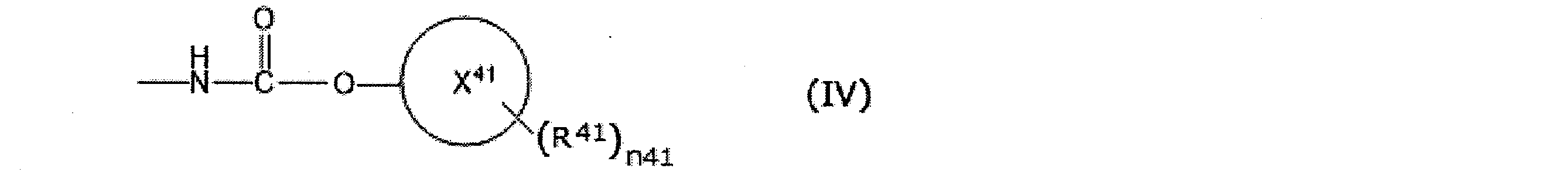

芳香族炭化水素環としては、例えば、ベンゼン環、ナフタレン環等が挙げられるが、ベンゼン環が好ましい。
複素芳香族環としては、例えば、ピリジン環等が挙げられる。 X 41 is an aromatic hydrocarbon ring or a heteroaromatic ring having 6 to 12 carbon atoms.
As an aromatic hydrocarbon ring, although a benzene ring, a naphthalene ring, etc. are mentioned, for example, a benzene ring is preferable.
Examples of heteroaromatic rings include pyridine rings and the like.
(7)上記化合物(V)を精製する工程 In this case, in the step (5), the compound (V) is separated from the reaction solution obtained in the step (4) together with the compound (III), and after the step (6), the following steps (7) It is preferable to recover a compound (V) by performing.
(7) Step of purifying the above compound (V)
工程(7)は、工程(5)又は工程(6)と同時に行うことができ、工程(1)~(5)を連続的に行うこともできる。 The method for purifying the compound (V) separated in the step (5) may be a known method, and examples thereof include distillation separation, liquid-liquid separation, solid-liquid separation, membrane separation and the like.
The step (7) can be performed simultaneously with the step (5) or the step (6), and the steps (1) to (5) can be performed continuously.
本発明の第2の実施形態の有機アミンの回収方法は、化合物(I)の製造方法で副生する高沸点化合物を含む液相成分から、化合物(III)を回収する方法であって、下記工程(A)、工程(B)及び工程(4)を含む。
工程(A):前記液相成分と水と化合物(III)とを混合する工程。
工程(B):前記液相成分と水とを反応器内で反応させる工程。
工程(4):前記反応器内の液相成分として、前記化合物(III)を含有する反応液を前記反応器外に排出する工程。
本実施形態の回収方法において、第1の実施形態の回収方法と同様の構成についてはその説明を省略する場合がある。 «Collection method»
The method for recovering an organic amine according to the second embodiment of the present invention is a method for recovering a compound (III) from a liquid phase component containing a high boiling point compound by-produced in the method for producing a compound (I), Step (A), step (B) and step (4) are included.
Process (A): The process of mixing the said liquid phase component, water, and a compound (III).
Step (B): a step of reacting the liquid phase component with water in a reactor.
Step (4): discharging the reaction liquid containing the compound (III) as the liquid phase component in the reactor to the outside of the reactor.
In the recovery method of the present embodiment, the description of the same configuration as that of the recovery method of the first embodiment may be omitted.
工程(A)は、化合物(I)の製造方法で副生する高沸点化合物を含む液相成分と水と化合物(III)とを混合する工程である。
ここで、化合物(I)の製造方法で副生する高沸点化合物を含む液相成分及び化合物(III)は前記第1の実施形態で記載の通りである。
工程(A)において使用される水の量は、前記液相成分に含有される、ビウレット基、アロファネート基、イソシアヌレート基、カルバメート基及びウレア基の総モル量に対して、化学量論比で、1倍以上200倍以下の範囲とすることが好ましい。
工程(A)において使用される化合物(III)の量は、水に対して、化学量論比(モル比)で、0.01倍以上200倍以下の範囲とすることが好ましい。
前記ビウレット基、アロファネート基、イソシアヌレート基、カルバメート基、ウレア基及びフリース転位末端の含有量は、前記第1の実施形態で記載の通りである。 [Step (A)]
The step (A) is a step of mixing a liquid phase component containing a high boiling point compound which is by-produced in the method for producing the compound (I), water, and the compound (III).
Here, the liquid phase component containing the high boiling point compound by-produced by the manufacturing method of compound (I) and compound (III) are as having described in the said 1st embodiment.
The amount of water used in step (A) is a stoichiometric ratio with respect to the total molar amount of biuret group, allophanate group, isocyanurate group, carbamate group and urea group contained in the liquid phase component. Preferably, it is in the range of 1 to 200 times.
The amount of the compound (III) used in the step (A) is preferably in the range of 0.01 times to 200 times the stoichiometric ratio (molar ratio) with respect to water.
The contents of the biuret group, the allophanate group, the isocyanurate group, the carbamate group, the urea group and the fleece rearrangement terminal are as described in the first embodiment.
工程(B)は、前記液相成分と水とを反応器内で反応させる工程である。
工程(B)における反応器内の温度は、100℃以上350℃以下の範囲が好ましく、150℃以上330℃以下の範囲がより好ましく、200℃以上300℃以下の範囲がさらに好ましい。
反応器内の圧力は、0.01kPa以上15MPa以下(絶対圧)の範囲であることが好ましく、減圧でも常圧でも加圧でも実施できる。
上記好ましい温度範囲や該分解反応で生成する化合物等を勘案すると、加圧での実施が好ましく、0.101MPa以上15MPa以下(絶対圧)の範囲がより好ましく、0.5MPa以上13MPa以下(絶対圧)の範囲がさらに好ましく、2MPa以上8MPa以下(絶対圧)の範囲が特に好ましい。
反応時間(連続反応の場合は滞留時間)は、0.01時間以上100時間以下で実施されることが好ましく、反応液を適宜サンプリングして、目的化合物である化合物(III)の生成量を測定し、所望の生成量に達する時間を反応時間とすることができる。 [Step (B)]
Step (B) is a step of reacting the liquid phase component with water in a reactor.
The temperature in the reactor in step (B) is preferably in the range of 100 ° C. to 350 ° C., more preferably in the range of 150 ° C. to 330 ° C., and still more preferably in the range of 200 ° C. to 300 ° C.
The pressure in the reactor is preferably in the range of 0.01 kPa or more and 15 MPa or less (absolute pressure), and may be carried out under reduced pressure, normal pressure or increased pressure.
In view of the above preferable temperature range and the compound etc. generated by the decomposition reaction, the implementation under pressure is preferable, the range of 0.101 MPa or more and 15 MPa or less (absolute pressure) is more preferable, and 0.5 MPa or more and 13 MPa or less (absolute pressure) The range of 2 MPa or more and 8 MPa or less (absolute pressure) is particularly preferable.
The reaction time (in the case of continuous reaction, residence time) is preferably 0.01 hour to 100 hours, and the reaction solution is appropriately sampled to measure the amount of compound (III) which is the target compound. The time to reach the desired amount of production can be the reaction time.
工程(4)は、前記反応器内の液相成分として、前記化合物(III)を含有する反応液を前記反応器外に排出する工程であり、前記第1の実施形態と同様に実施することができる。 [Step (4)]
The step (4) is a step of discharging the reaction liquid containing the compound (III) as a liquid phase component in the reactor to the outside of the reactor, and is carried out in the same manner as the first embodiment. Can.
本実施形態の回収方法において用いられる回収装置として、前記第1の実施形態と同様の回収装置を用いることができるが、以下に示す回収装置も使用することができる。 (Collection device)
Although the same recovery device as that of the first embodiment can be used as a recovery device used in the recovery method of this embodiment, the recovery device described below can also be used.
図8Aに示す回収装置は、化合物(I)の製造工程で副生する液相成分と水とを反応させる攪拌槽(耐圧反応器)C101;化合物(I)の製造工程で副生する液相成分、水及び化合物(III)を攪拌槽C101に供給するラインC1;及び、攪拌槽C101で得られた液相成分を排出するラインC5を有する。
図8Aに示す回収装置は、必要に応じて、さらに、送液ポンプ、流量計、温度計等の計装機器、熱交換器等の公知のプロセス装置を備えていてもよい。 FIG. 8A is a schematic configuration view showing an example of a recovery apparatus used in the recovery method of the present embodiment, and (1) a tank-type reactor is used as a reactor.
The recovery apparatus shown in FIG. 8A is a stirring tank (pressure-resistant reactor) C101 in which a liquid phase component by-produced in the production process of compound (I) and water are reacted; a liquid phase by-produced in the production process of compound (I) A line C1 for supplying the component, water and the compound (III) to the stirring tank C101; and a line C5 for discharging the liquid phase component obtained in the stirring tank C101.
The recovery apparatus shown in FIG. 8A may further include known process devices such as a liquid transfer pump, flowmeters, instrumentation devices such as a thermometer, and a heat exchanger, as necessary.
図8Bに示す回収装置は、化合物(I)の製造工程で副生する液相成分と水とを反応させる攪拌槽(耐圧反応器)C101;攪拌槽C101における分解反応で生じた液相成分を収容する貯槽C103;攪拌槽C101で副生された気相成分の排出を許容する圧力を保持する保圧弁C104;化合物(I)の製造工程で副生する液相成分、水及び化合物(III)を攪拌槽C101に供給するラインC1;攪拌槽C101で生じた気相成分を排出するラインC4;及び、攪拌槽C101で得られた液相成分を貯槽C103に送るラインC5を有する。
図8Bに示す回収装置は、必要に応じて、さらに、送液ポンプ、流量計、温度計等の計装機器、熱交換器等の公知のプロセス装置を備えていてもよい。また、図8Bに示す回収装置は、必要に応じて、複数個の槽型反応器を連結して備えてもよい。 FIG. 8B is a schematic configuration view showing another example of the recovery device used in the recovery method of the present embodiment, which is a (1) tank type reactor as a reactor.
In the recovery apparatus shown in FIG. 8B, a stirring tank (pressure-resistant reactor) C101 in which a liquid phase component by-produced in the production process of compound (I) and water are reacted; Reservoir C103 to be accommodated; Pressure holding valve C104 for holding a pressure permitting discharge of the gas phase component by-produced in the stirring tank C101; liquid phase component by-produced in the production process of compound (I) Are supplied to the stirring tank C101; a line C4 for discharging the gas phase component generated in the stirring tank C101; and a line C5 for sending the liquid phase component obtained in the stirring tank C101 to the storage tank C103.
The recovery apparatus illustrated in FIG. 8B may further include known process devices such as a liquid transfer pump, flowmeters, instrumentation devices such as a thermometer, and a heat exchanger, as necessary. Moreover, the recovery apparatus shown to FIG. 8B may connect and comprise several tank-type reactors as needed.
図9に示す回収装置は、化合物(I)の製造工程で副生する液相成分と水を反応させる押出機C201;押出機C201における分解反応で副生した気相成分を抜き出すベント口C202;押出機C201における分解反応で生じた液相成分の排出を許容する圧力を保持する保圧弁C203;押出機C201で副生された気相成分の排出を許容する圧力を保持する保圧弁C204;化合物(I)の製造工程で副生する液相成分、水及び化合物(III)を押出機C201に供給するラインC20;ベント口C202から抜き出された気相成分を排出するラインC21;及び押出機C201で得られた液相成分を排出するラインC22を有する。
図9において、ベント口C202が1つ記載されているが、複数あってもよい。
ラインC20、C21及びC22も1つのみ記載されているが、複数あってもよい。 FIG. 9 is a schematic configuration view showing an example of a recovery device used in the recovery method of the present embodiment, and (2) an extruder is used as a reactor.
The recovery apparatus shown in FIG. 9 is an extruder C201 in which a liquid phase component by-produced in the production process of compound (I) and water are reacted; a vent port C202 for extracting a gas phase component by-produced in the decomposition reaction in the extruder C201; Pressure holding valve C203 which holds the pressure which permits discharge of the liquid phase component generated in the decomposition reaction in the extruder C201; pressure holding valve C204 which holds the pressure which allows discharge of the gas phase components byproduced in the extruder C201; Line C20 for supplying the liquid phase component by-produced in the production process of (I), water and compound (III) to the extruder C201; line C21 for discharging gas phase components extracted from the vent port C202; and extruder It has a line C22 for discharging the liquid phase component obtained in C201.
Although one vent port C 202 is described in FIG. 9, a plurality of vent ports C 202 may be provided.
Although only one line C20, C21 and C22 is described, there may be more than one.
図10に示す回収装置は、化合物(I)の製造工程で副生する液相成分と水とを反応させる押出機C301;押出機C301における分解反応で副生した気相成分を抜き出すベント口C302;ベント口C302から気相成分の排出を許容する圧力を保持する保圧弁C304;押出機C301から排出される液相成分を回収する受器C305;受器C305から液相成分の排出を許容する圧力を保持する保圧弁C303;化合物(I)の製造工程で副生する液相成分、水及び化合物(III)を押出機C301に供給するラインC30;ベント口C302から抜き出された気相成分を排出するラインC31;及び受器C305から液相成分を排出するラインC32を有する。 Moreover, FIG. 10 is a schematic block diagram which shows another example of the collection | recovery apparatus which is used in the collection | recovery method of this embodiment, and (2) extruder is used as a reactor.
In the recovery apparatus shown in FIG. 10, an extruder C301 for reacting liquid phase components by-produced in the production process of compound (I) with water; and a vent port C302 for extracting gas phase components by-produced in the decomposition reaction in the extruder C301. A pressure holding valve C304 which holds a pressure permitting discharge of the gas phase component from the vent port C302; a receiver C305 which recovers a liquid phase component discharged from the extruder C301; allowing the discharge of the liquid phase component from the receiver C305; Pressure holding valve C303; liquid phase component by-produced in compound (I) production process, water and compound (III) line C30 for supplying extruder C301; gas phase component extracted from vent port C302 And a line C32 for discharging the liquid phase component from the receiver C305.
図11に示す回収装置は、化合物(I)の製造工程で副生する液相成分と水とを反応させる加熱蒸発面C401を具備する薄膜蒸発機C402;加熱蒸発面C401における分解反応で生じた液相成分を回収する回収部C403;化合物(I)の製造工程で副生する液相成分、水及び化合物(III)を薄膜蒸発機C402に供給するラインC40;加熱蒸発面B601で副生した気相成分を排出するラインC41;及び、回収部C403から液相成分を排出するラインC42を有する。 FIG. 11 is a schematic configuration view showing an example of a recovery apparatus which is used in the recovery method of the present embodiment and (3) a thin film evaporator is used as a reactor.
The recovery apparatus shown in FIG. 11 was produced by a decomposition reaction on a thin-film evaporator C402 having a heating evaporation surface C401 for reacting liquid phase components by-produced in the production process of compound (I) with water; Recovery part C403 for recovering liquid phase components; line C40 for supplying liquid phase components, water and compound (III) by-produced in the production process of compound (I) to thin-film evaporator C402; A line C41 for discharging a gas phase component; and a line C42 for discharging a liquid phase component from the recovery unit C403.
図7に示す回収装置は、化合物(I)の製造工程で副生する液相成分と活性水素含有化合物とを反応させる加熱蒸発面B701と、加熱蒸発面B701における分解反応で副生した気相成分を冷却する凝縮器B704とを具備する薄膜蒸発機B702;加熱蒸発面B701における分解反応で生じた液相成分を回収する回収部B703;化合物(I)の製造工程で副生する液相成分を薄膜蒸発機B702に供給するラインB70;凝縮器B704で凝縮されなかった気相成分を排出するラインB71;凝縮器B704で冷却されて得られた凝縮液を排出するラインB73;及び、回収部B703に回収された液相成分を排出するラインB72を有する。 FIG. 7 is a schematic configuration view showing another example of a recovery apparatus which is used in the recovery method of the present embodiment and (3) a thin film evaporator is used as a reactor.
The recovery apparatus shown in FIG. 7 has a heating evaporation surface B 701 in which a liquid phase component by-produced in the production process of compound (I) and an active hydrogen-containing compound are reacted, and a vapor phase by-produced by decomposition reaction in the heating evaporation surface B 701. Thin-film evaporator B702 equipped with a condenser B704 for cooling the components; recovery part B703 for recovering liquid phase components generated by decomposition reaction on the heating evaporation surface B701; liquid phase components by-produced in the production process of compound (I) Are supplied to a thin film evaporator B702; a line B71 for discharging a gas phase component not condensed by the condenser B704; a line B73 for discharging a condensate obtained by cooling the condenser B704; B703 has a line B72 for discharging the liquid phase component recovered.
(1)NMR分析方法
装置:日本国、日本電子(株)社製JNM-A400 FT-NMRシステム
・1H-NMR分析サンプルの調製
サンプル溶液を0.3g秤量し、重クロロホルムを0.7gと内部標準物質としてテトラメチルスズを0.05g加えて均一に混合した溶液をNMR分析サンプルとした。
・定量分析法
各標準物質について分析を実施し、作成した検量線を基に、分析サンプル溶液の定量分析を実施した。 <Analytical method>
(1) NMR analysis method Device: JNM-A400 FT-NMR system manufactured by Nippon Denshi Co., Ltd. Japan Preparation of 1 H-NMR analysis sample 0.3 g of a sample solution was weighed, and 0.7 g of heavy chloroform was used. A solution in which 0.05 g of tetramethyl tin was added as an internal standard substance and uniformly mixed was used as an NMR analysis sample.
-Quantitative analysis method The analysis was performed for each standard substance, and the quantitative analysis of the analysis sample solution was performed based on the prepared calibration curve.
装置:日本国、島津製作所社製、GC-14B
カラム:Porapack N
直径3mm、長さ3m、SUS製
カラム温度:60℃
注入口温度:120℃
キャリアガス:ヘリウム
キャリアガス流量:40mL/min
検出器:FID(水素炎イオン化型検出器)
・ガスクロマトグラフィー分析サンプル
サンプル溶液を1.0g秤量し、トルエンを10gと内部標準物質としてn-ヘキサンを0.1g加えて均一に混合した溶液をガスクロマトグラフィー分析サンプルとした。 (2) Gas chromatography analysis method Apparatus: Japan, Shimadzu Corporation make, GC-14B
Column: Porapack N
3 mm in diameter, 3 m in length, made of SUS Column temperature: 60 ° C
Inlet temperature: 120 ° C
Carrier gas: Helium carrier gas flow rate: 40 mL / min
Detector: FID (hydrogen flame ionization detector)
-Gas chromatography analysis sample 1.0 g of a sample solution was weighed, 10 g of toluene and 0.1 g of n-hexane as an internal standard substance were added and uniformly mixed to obtain a gas chromatography analysis sample.
装置:日本国、島津製作所社製、LC-10AT
カラム:Inertsil ODS
粒子径5μm、内径2.1mm、長さ250mm
カラム温度:40℃
展開溶媒:水/アセトニトリル=90/10
展開溶媒流量:1mL/min
検出器:フォトダイオードアレイ検出器
・液体クロマトグラフィー分析サンプル
サンプル溶液を1.0g秤量し、酢酸を10g加えて均一に混合した溶液を液体クロマトグラフィー分析サンプルとした。
・定量分析法
各標準物質について分析を実施し、作成した検量線を基に、分析サンプル溶液の定量分析を実施した。 (3) Liquid chromatography analysis method Device: Japan, Shimadzu Corporation LC-10AT
Column: Inertsil ODS
Particle size 5 μm, inner diameter 2.1 mm, length 250 mm
Column temperature: 40 ° C
Developing solvent: water / acetonitrile = 90/10
Developing solvent flow rate: 1 mL / min
Detector: Photodiode array detector liquid chromatography analysis sample 1.0 g of a sample solution was weighed, 10 g of acetic acid was added, and a uniformly mixed solution was used as a liquid chromatography analysis sample.
-Quantitative analysis method The analysis was performed for each standard substance, and the quantitative analysis of the analysis sample solution was performed based on the prepared calibration curve.
工程(1-A):化合物(I)の製造で副生する高沸点化合物を含む液相成分を得る工程
(カルバメートの製造)
図12に示す装置を使用した。
2,4-トルエンジアミン9.8kg、尿素10.3kg、4-(1,1,3,3-テトラメチルブチル)フェノール261.9kgの混合物を90kg/HrでラインA1より連続多段蒸留塔A101に供給した。
連続多段蒸留塔A101は、カルバメート化工程を行うための装置であり、リボイラーA111で加熱することで塔底温度を250℃とし、塔頂圧力5kPaとした。
連続多段蒸留塔A101の底部より反応液を90.7kg/Hrで抜き出した。
連続多段蒸留塔A101の塔頂部より気相成分を抜き出し、ラインA3を通して凝縮器A103に導入した。凝縮器A103に導入された気相成分は、凝縮器A103で100℃に冷却され、4-(1,1,3,3-テトラメチルブチル)フェノールと尿素との混合液を得た。ラインA4より、凝縮器A103で得られた4-(1,1,3,3-テトラメチルブチル)フェノールと尿素との混合液を9kg/HrでラインA1に供給した。
凝縮器A103で凝縮されなかった気相成分は、ラインA9を通して、凝縮器A103から排出した。 Example 1
Step (1-A): Step of obtaining a liquid phase component containing a high boiling point compound by-produced in the production of compound (I) (production of carbamate)
The apparatus shown in FIG. 12 was used.
A mixture of 9.8 kg of 2,4-toluenediamine, 10.3 kg of urea, and 261.9 kg of 4- (1,1,3,3-tetramethylbutyl) phenol at 90 kg / hr from line A1 into continuous multistage distillation column A101 Supplied.
Continuous multistage distillation column A101 is an apparatus for performing a carbamate process, The bottom temperature was 250 degreeC by heating with reboiler A111, and it was referred to as 5 kPa top pressure.
The reaction solution was withdrawn at 90.7 kg / hr from the bottom of the continuous multistage distillation column A101.
The gas phase component was extracted from the top of continuous multistage distillation column A101, and was introduced into condenser A103 through line A3. The gas phase component introduced into the condenser A103 was cooled to 100 ° C. by the condenser A103 to obtain a mixed liquid of 4- (1,1,3,3-tetramethylbutyl) phenol and urea. From line A4, a mixture of 4- (1,1,3,3-tetramethylbutyl) phenol and urea obtained in condenser A103 was supplied to line A1 at 9 kg / Hr.
The gas phase components not condensed in the condenser A103 were discharged from the condenser A103 through a line A9.
連続多段蒸留塔A101の底部より反応液を、ラインA5を経て熱分解装置A102に供給した。熱分解装置A102は、カルバメートの熱分解反応によってイソシアネートを生成するための装置であり、管型反応器と、前記液相成分とイソシアネートを含む気相成分を分離する分離槽からなるものであった。内部圧力を1kPaとし、外部加熱により250℃に加熱した。 (Thermal decomposition of carbamate)
The reaction solution was supplied from the bottom of the continuous multistage distillation column A101 to the thermal decomposition apparatus A102 through a line A5. The thermal decomposition apparatus A102 is an apparatus for producing an isocyanate by a thermal decomposition reaction of carbamate, and comprises a tubular reactor and a separation tank for separating the liquid phase component and the gas phase component containing isocyanate. . The internal pressure was set to 1 kPa, and was heated to 250 ° C. by external heating.
分離塔A109の塔底より4-(1,1,3,3-テトラメチルブチル)フェノールをラインA18から回収した。 The gas phase component generated in the thermal decomposition apparatus A102 is supplied at 8 m / s from the line A7 to the separation tower A109, and 4- (1,1,3,3-tetramethylbutyl) phenol and 2,4-toluene diisocyanate The separation was done. The amount of heat required for distillation separation was supplied from reboiler A112.
4- (1,1,3,3-tetramethylbutyl) phenol was recovered from line A18 from the bottom of separation column A109.
精製塔A110の塔頂より、凝縮器A115及びラインA17を経て2,4-トルエンジイソシアネートが2.4kg/Hrで回収された。
精製塔A110の塔底成分はラインA19より抜き出した。 The component containing 2,4-toluene diisocyanate recovered from the top of separation column A109 was supplied to purification column A110 via condenser A114 and line A20 to carry out distillation purification of 2,4-toluene diisocyanate. The heat quantity required for distillation purification was supplied from reboiler A113.
From the top of the purification column A110, 2,4-toluene diisocyanate was recovered at 2.4 kg / Hr via a condenser A115 and a line A17.
The bottom component of the purification column A110 was withdrawn from line A19.
ラインA8より回収した液相成分を1H-NMRにて分析したところ、液相成分1kgあたり、カルバメート結合を0.90モル、基(II-1)と基(II-2)を合わせて0.13モル、アロファネート結合とイソシアヌレート結合を合わせて0.12モル、フリース転位末端を0.22モル含んでいた。
また、液体クロマトグラフィー分析の結果、該液相成分は、下記式(1-a-1)で表される化合物および下記式(1-b-1)で表される化合物を含み、4-(1,1,3,3-テトラメチルブチル)フェノールを57質量%含んでいた。 The viscosity at 150 ° C. of the liquid phase component recovered from line A8 was 70 mPa · s.
The liquid phase component recovered from line A8 is analyzed by 1 H-NMR to find that 0.90 mol of carbamate bond, 1 group (II-1) and 1 group (II-2) are combined per 1 kg of liquid phase component. .13 moles, 0.12 moles of allophanate bond and isocyanurate bond combined, 0.22 mole of Fries rearrangement end.
In addition, as a result of liquid chromatography analysis, the liquid phase component contains a compound represented by the following formula (1-a-1) and a compound represented by the following formula (1-b-1), It contained 57% by mass of 1,1,3,3-tetramethylbutyl) phenol.
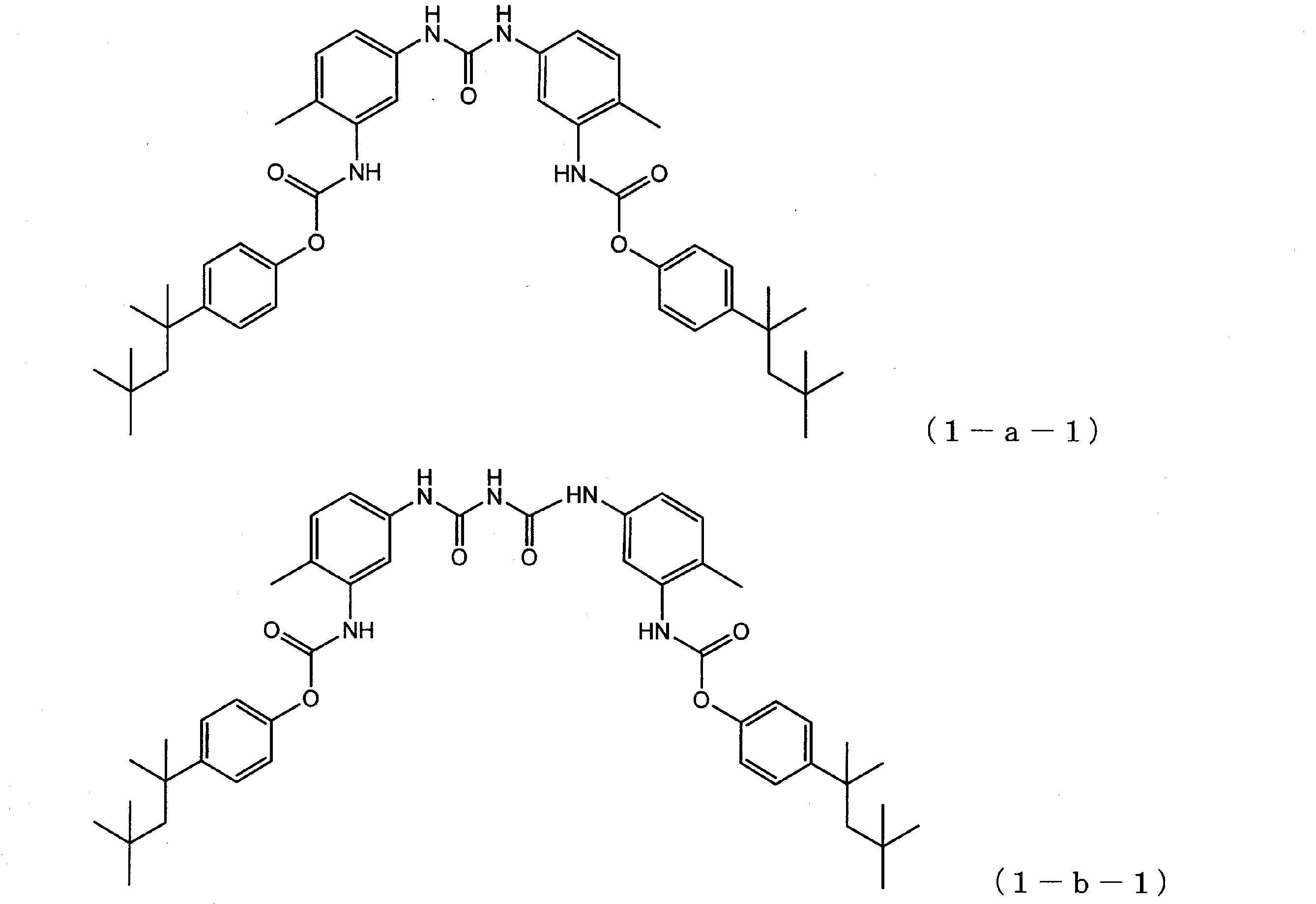
図1に示す装置を使用した。ラインA8を経て回収した高沸点化合物を含む液相成分50kgを180℃に保持した状態でラインB1を通じて耐圧反応器B101に供給した。次いで水100kgを耐圧反応器B101に供給し混合液とした。該耐圧反応器B101を280℃、圧力6.5MPaで5時間加熱した。 Step (1-1): Step of reacting a liquid phase component containing a high boiling point compound with an active hydrogen-containing compound An apparatus shown in FIG. 1 was used. 50 kg of the liquid phase component containing the high boiling point compound recovered through the line A8 was supplied to the pressure resistant reactor B101 through the line B1 in a state of being maintained at 180 ° C. Next, 100 kg of water was supplied to the pressure resistant reactor B101 to make a mixed solution. The pressure-resistant reactor B101 was heated at 280 ° C. and a pressure of 6.5 MPa for 5 hours.
前記工程(1-1)において耐圧容器内B101の気相成分をラインB3を通して凝縮器B102に導入した。凝縮器B102に導入された気相成分は、凝縮器B102で10℃に冷却され、凝縮液を得、これをラインB2を通して該耐圧容器B101に戻した。前記工程(1-1)をおこなっている間、この工程を継続しておこなった。 Step (1-2): Step of returning the condensate obtained by cooling the gas phase component back to the reactor In the step (1-1), the gas phase component in the pressure container B101 is condensed via the line B3 to the condenser B102 Introduced to The gas phase component introduced into the condenser B102 was cooled to 10 ° C. by the condenser B102 to obtain a condensate, which was returned to the pressure resistant vessel B101 through the line B2. This step was continued while the step (1-1) was being performed.
前記工程(1-2)において凝縮されなかった気相成分は、保圧弁B104よりラインB4を通じてガス成分(分析の結果、二酸化炭素が主成分であった)として抜き出した。前記工程(1-1)をおこなっている間、この工程を継続しておこなった。 Step (1-3): Step of discharging non-condensed gas phase component to other than the reactor The gas phase component not condensed in the above step (1-2) As a result of analysis, carbon dioxide was extracted as the main component). This step was continued while the step (1-1) was being performed.
前記工程(1-1)をおこない、冷却した後、ラインB5を通じて貯槽B103に反応液を回収した。反応液をガスクロマトグラフィーにて分析したところ、2,4-トルエンジアミンが8.3モル含まれていた。 Step (1-4): Step of discharging the reaction solution to the outside of the reactor The step (1-1) was performed, and after cooling, the reaction solution was recovered in the storage tank B103 through the line B5. The reaction mixture was analyzed by gas chromatography to find that 8.3 moles of 2,4-toluenediamine was contained.
回収した反応液を減圧蒸留し、粗2,4-トルエンジアミンを回収した。収率は80%であった。 Step (1-5): Step of separating compound (III) The recovered reaction liquid was distilled under reduced pressure to recover crude 2,4-toluenediamine. The yield was 80%.
前記工程(1-5)で回収した粗2,4-トルエンジアミンを蒸留精製した。回収した2,4-トルエンジアミンは純度が99質量%以上(ガスクロマトグラフィーの分析誤差を含む)であった。また、2,4-トルエンジアミンの総質量に対する金属原子含有量は1000ppm未満、ハロゲン原子含有量は1000ppm未満であった。 Step (1-6): Step of purifying compound (III) The crude 2,4-toluenediamine recovered in the above step (1-5) was purified by distillation. The recovered 2,4-toluenediamine had a purity of 99% by mass or more (including an analysis error of gas chromatography). In addition, the metal atom content relative to the total mass of 2,4-toluenediamine was less than 1000 ppm, and the halogen atom content was less than 1000 ppm.
前記工程(1-5)で、化合物(III)を回収した後の残留液を減圧蒸留し、粗4-(1,1,3,3-テトラメチルブチル)フェノールを回収した。収率は81%であった。 Step (1-7): Step of separating compound (V) The residual liquid after recovering compound (III) in the above step (1-5) is distilled under reduced pressure to obtain crude 4- (1,1,3,3) 3-Tetramethylbutyl) phenol was recovered. The yield was 81%.
前記工程(1-7)で回収した粗4-(1,1,3,3-テトラメチルブチル)フェノールを蒸留精製した。回収した4-(1,1,3,3-テトラメチルブチル)フェノールは純度が99質量%以上(ガスクロマトグラフィーの分析誤差を含む)であった。また、4-(1,1,3,3-テトラメチルブチル)フェノールの総質量に対する金属原子含有量は1000ppm未満、ハロゲン原子含有量は1000ppm未満であった。 Step (1-8): Step of purifying compound (V) The crude 4- (1,1,3,3-tetramethylbutyl) phenol recovered in the above step (1-7) was purified by distillation. The recovered 4- (1,1,3,3-tetramethylbutyl) phenol had a purity of 99% by mass or more (including an analysis error of gas chromatography). In addition, the metal atom content relative to the total mass of 4- (1,1,3,3-tetramethylbutyl) phenol was less than 1000 ppm, and the halogen atom content was less than 1000 ppm.
工程(1-6)と工程(1-8)で回収した2,4-トルエンジアミンと4-(1,1,3,3-テトラメチルブチル)フェノールを使用し、不足分の2,4-トルエンジアミンと4-(1,1,3,3-テトラメチルブチル)フェノールは新たに追加して、ラインA1より連続多段蒸留塔A101に供給し、工程(1-A)をおこなったところ、ライン17より2,4-トルエンジイソシアネートが2.4kg/Hrで回収された。 Step (1-B): Preparation of Compound (I) by Recycling Compound (III) and Compound (V) Recovered 2,4-toluene Recovered in Step (1-6) and Step (1-8) 2,4-toluenediamine and 4- (1,1,3,3-tetramethylbutyl) phenol are newly added using diamine and 4- (1,1,3,3-tetramethylbutyl) phenol The mixture was supplied to line A1 continuously to multistage distillation column A101 to carry out step (1-A). As a result, 2,4-toluene diisocyanate was recovered from line 17 at 2.4 kg / Hr.
工程(2-A)
(カルバメートの製造)
図13に示す装置を使用し、カルバメート化工程をおこなった。1-アミノ-3-アミノメチル-3,5,5-トリメチルシクロヘキサン11.3kg、尿素15.1kg、1-ブタノール220.3kgの混合物を20kg/HrでラインA21より連続多段蒸留塔A201に供給した。ラインA25からは適宜、1-ブタノールを供給した。
連続多段蒸留塔A201で生じた気相成分は、ラインA23を通して、凝縮器A203に導入された。凝縮器A203に導入された気相成分は、0℃に冷却されて、1-ブタノールと尿素との混合液を得た。当該混合液の一部は、ラインA24より、3.5kg/Hrで連続多段蒸留塔A201に供給し残部は貯槽A204に回収した。
連続多段蒸留塔A201は、カルバメート化工程を行うための装置であり、リボイラーA202で加熱することにより塔底温度を220℃とし、塔頂圧力1.2MPaとした。
連続多段蒸留塔A201の底部より反応液を抜き出し、ラインA22を経て貯槽A205に回収した。 Example 2
Process (2-A)
(Production of carbamate)
The carbamate process was carried out using the apparatus shown in FIG. A mixture of 11.3 kg of 1-amino-3-aminomethyl-3,5,5-trimethylcyclohexane, 15.1 kg of urea and 220.3 kg of 1-butanol was supplied to the continuous multistage distillation column A201 at 20 kg / hr from line A21. . 1-Butanol was suitably supplied from line A25.
The gas phase components generated in the continuous multistage distillation column A201 were introduced into the condenser A203 through the line A23. The gas phase component introduced into the condenser A203 was cooled to 0 ° C. to obtain a mixture of 1-butanol and urea. A portion of the mixed solution was supplied to the continuous multistage distillation column A201 at 3.5 kg / Hr from the line A24, and the remaining portion was collected in the storage tank A204.
The continuous multistage distillation column A201 is an apparatus for performing a carbamate process, and the bottom temperature is adjusted to 220 ° C. and the top pressure is 1.2 MPa by heating with a reboiler A202.
The reaction liquid was extracted from the bottom of the continuous multistage distillation column A201, and was collected in the storage tank A205 through the line A22.
次に図14に示す装置を使用して、予備濃縮工程をおこなった。カルバメート化工程で貯槽A205に回収した反応液を、ラインA31を通して21kg/Hrで薄膜蒸発器A301に供給した。薄膜蒸発器A301は加熱蒸発面の温度を130℃、内部の圧力を70kPaとした。
薄膜蒸発器A301で生成した気相成分は凝縮器A302で凝縮し、貯槽A304に回収した。回収物は1-ブタノールであった。
一方、薄膜蒸発器A301で生成した液相成分を、ラインA32を経て貯槽A303に10kg/Hrで回収した。 (Preconcentration)
Next, a preconcentration step was performed using the apparatus shown in FIG. The reaction liquid collected in the storage tank A205 in the carbamate forming step was supplied to the thin film evaporator A301 at 21 kg / Hr through the line A31. In the thin film evaporator A301, the temperature of the heating evaporation surface was 130 ° C., and the internal pressure was 70 kPa.
The gas phase component generated by the thin film evaporator A301 was condensed by the condenser A302 and recovered to the storage tank A304. The recovery was 1-butanol.
On the other hand, the liquid phase component generated by the thin film evaporator A301 was recovered at 10 kg / Hr in the storage tank A303 via the line A32.
図15に示す装置を使用して、熱分解工程をおこなった。熱分解装置A401は、N-置換カルバメートの熱分解反応によってイソホロンジイソシアネートを生成するための多段蒸留塔であり、塔頂圧力を25kPaとし、リボイラーA403で加熱することでジベンジルエーテルの全還流状態とした。ここにラインA40より予備濃縮工程で貯槽A303に回収した液相成分を5kg/Hrで供給し、ラインA49よりジベンジルエーテルを供給した。気相成分は塔頂より抜き出し、凝縮器A402を経てラインA42より回収し、液相成分はラインA41より回収した。
熱分解装置A401の中段に設けたラインA43よりイソホロンジイソシアネートを含む留分を回収し分離塔A404に供給した。分離塔A404にて1-ブタノールを含む気相成分を蒸留分離し、該気相成分は凝縮器A405を経てラインA44より回収した。蒸留分離に必要な熱量はリボイラーA406より供給した。
分離塔A404の塔底部から回収された液相成分を、ラインA45及びラインA46を経て分離塔A407に供給した。分離塔A407では液相成分を蒸留分離し、ラインA48より回収した。分離塔A407にて蒸留分離に必要な熱量はリボイラーA409より供給した。
分離塔A404の塔頂より回収した気相成分は、凝縮器A408で凝縮し、ラインA47よりイソホロンジイソシアネートを回収した。 (Thermal decomposition of carbamate)
The thermal decomposition process was performed using the apparatus shown in FIG. The thermal decomposition apparatus A401 is a multistage distillation column for producing isophorone diisocyanate by the thermal decomposition reaction of N-substituted carbamate, and the pressure at the top of the column is 25 kPa and heating with a reboiler A403 gives a total reflux condition of dibenzyl ether did. The liquid phase component recovered to the storage tank A 303 in the preconcentration step from line A40 was supplied at 5 kg / Hr, and dibenzyl ether was supplied from line A49. The gas phase component was withdrawn from the top of the column, and was recovered from the line A42 via the condenser A402, and the liquid phase component was recovered from the line A41.
The fraction containing isophorone diisocyanate was recovered from a line A43 provided in the middle stage of the thermal decomposition apparatus A401 and supplied to the separation column A404. The gas phase component containing 1-butanol was separated by distillation in separation column A404, and the gas phase component was recovered from line A44 via condenser A405. The amount of heat required for distillation separation was supplied from reboiler A406.
The liquid phase component recovered from the bottom of separation column A404 was supplied to separation column A407 via line A45 and line A46. In the separation column A407, liquid phase components were separated by distillation and recovered from the line A48. The heat required for distillation separation in separation column A407 was supplied from reboiler A409.
The gas phase component recovered from the top of the separation column A404 was condensed by the condenser A408, and isophorone diisocyanate was recovered from the line A47.
該高沸点化合物を含む液相成分の粘度は150℃において40mPa・sであった。
当該液相成分を1H-NMRにて分析したところ、液相成分1kgあたり、カルバメート結合を2.56モル、基(II-1)と基(II-2)を合わせて0.14モル、アロファネート結合とイソシアヌレート結合を合わせて0.10モルとジベンジルエーテルを含有する混合物であった。
当該液相成分を液体クロマトグラフィーにて分析したところ、下記式(2-a-1)で表される化合物および下記式(2-b-1)で表される化合物を含んでいた。 The liquid phase component recovered from line A41 was used as the liquid phase component containing the high boiling point compound of the present embodiment.
The viscosity of the liquid phase component containing the high boiling point compound was 40 mPa · s at 150 ° C.
The liquid phase component was analyzed by 1 H-NMR to find that 2.56 mol of a carbamate bond, 0.14 mol of a combination of the group (II-1) and the group (II-2) were obtained per 1 kg of the liquid phase component. The combination of allophanate bond and isocyanurate bond was a mixture containing 0.10 mol and dibenzyl ether.
The liquid phase component was analyzed by liquid chromatography, and it contained a compound represented by the following formula (2-a-1) and a compound represented by the following formula (2-b-1).
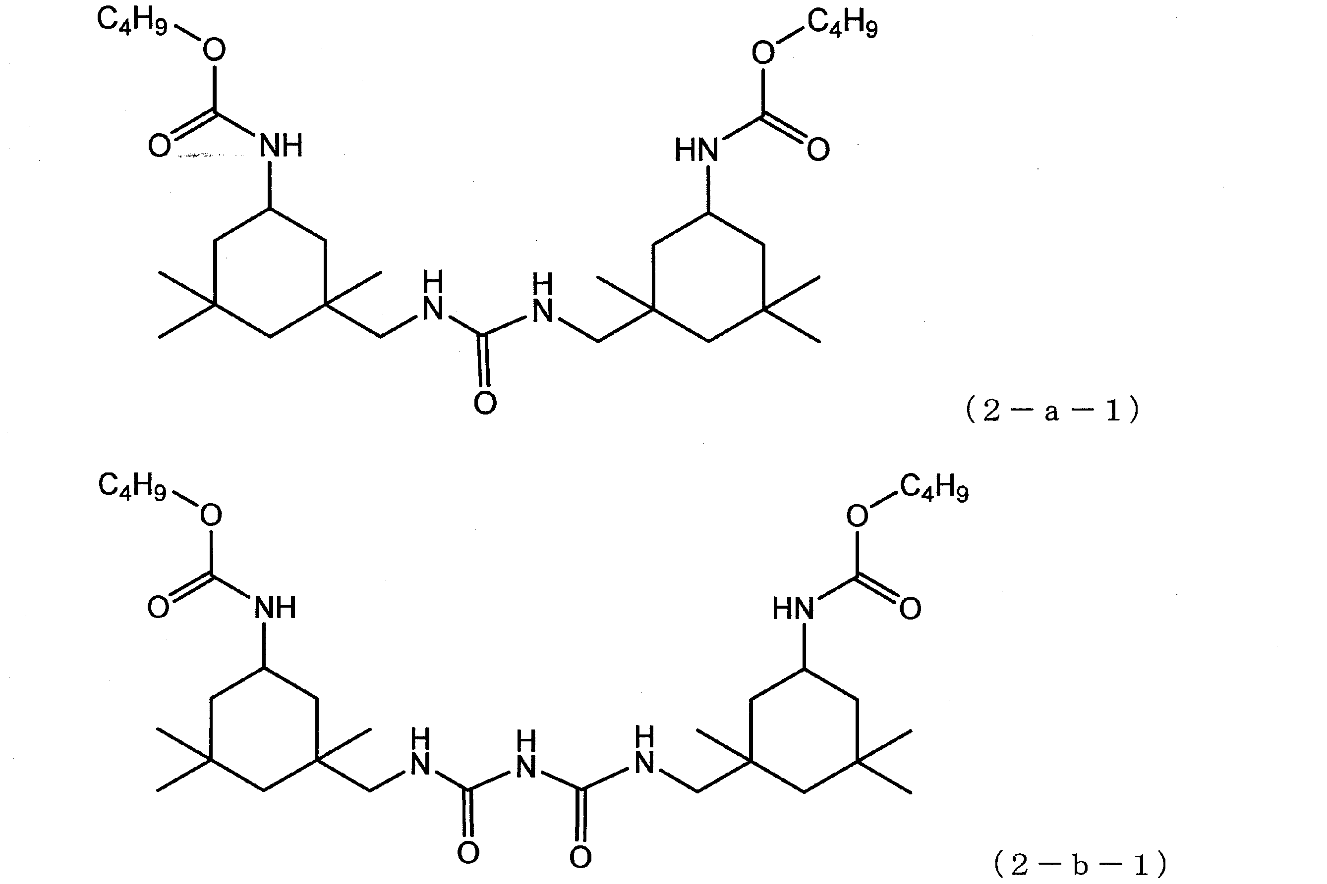
図2に示す装置を使用した。ラインA41を経て回収した高沸点化合物を含む液相成分50kgを180℃に保持した状態でラインB20を通じて耐圧反応器B201に供給した。
耐圧反応器B201に水100kgとエタノール16kgを添加したのち、ポンプB202により、ラインB21とラインB22を経由して液相成分を循環させながら250℃、4.3MPaで5時間反応をおこなった。 Step (2-1): Step of reacting a liquid phase component containing a high boiling point compound with an active hydrogen-containing compound An apparatus shown in FIG. 2 was used. 50 kg of the liquid phase component containing the high boiling point compound recovered through the line A41 was supplied to the pressure resistant reactor B201 through the line B20 while being maintained at 180 ° C.
After adding 100 kg of water and 16 kg of ethanol to the pressure resistant reactor B201, the reaction was carried out at 250 ° C. and 4.3 MPa for 5 hours while circulating the liquid phase component by the pump B202 via the line B21 and the line B22.
工程(2-1)において耐圧反応器B201内の気相成分を、ラインB24を通して、凝縮器B203に導入した。導入された気相成分を、凝縮器B203で10℃に冷却して得た凝縮液を、ラインB23を通して耐圧反応器B201に戻した。工程(2-1)をおこなっている間、この工程を継続しておこなった。 Step (2-2): returning the condensate obtained by cooling the gas phase component back into the reactor In the step (2-1), the gas phase component in the pressure resistant reactor B201 is passed through the line B24 It was introduced into the condenser B203. The condensate obtained by cooling the introduced gas phase component to 10 ° C. in the condenser B203 was returned to the pressure resistant reactor B201 through the line B23. This process was continued while performing the process (2-1).
工程(2-2)において凝縮されなかった気相成分を、保圧弁B204よりガス成分(分析の結果、二酸化炭素が主成分であった)としてラインB26を通して抜き出した。工程(2-1)をおこなっている間、この工程を継続しておこなった。 Step (2-3): The step of discharging the non-condensed gas phase component out of the reactor Other than the step (2-2), the gas phase component not condensed in the step (2-2) It was extracted through line B26 as carbon dioxide was the main component). This process was continued while performing the process (2-1).
工程(2-1)をおこない、冷却した後、反応液をラインB25を通して貯槽B205に回収した。
反応液をガスクロマトグラフィーにて分析したところ、1-アミノ-3-アミノメチル-3,5,5-トリメチルシクロヘキサンが含まれていた。 Step (2-4): Step of discharging the reaction solution out of the reactor Step (2-1) was carried out, and after cooling, the reaction solution was recovered through line B25 into the storage tank B205.
The reaction solution was analyzed by gas chromatography to find that it contained 1-amino-3-aminomethyl-3,5,5-trimethylcyclohexane.
回収した反応液を減圧蒸留し、粗1-アミノ-3-アミノメチル-3,5,5-トリメチルシクロヘキサンを回収した。収率は90%であった。 Step (2-5): Step of separating compound (III) The recovered reaction liquid was distilled under reduced pressure to recover crude 1-amino-3-aminomethyl-3,5,5-trimethylcyclohexane. The yield was 90%.
工程(2-5)で回収した粗1-アミノ-3-アミノメチル-3,5,5-トリメチルシクロヘキサンを蒸留精製した。回収した1-アミノ-3-アミノメチル-3,5,5-トリメチルシクロヘキサンは純度が99質量%以上(ガスクロマトグラフィーの分析誤差を含む)であった。また、1-アミノ-3-アミノメチル-3,5,5-トリメチルシクロヘキサンの総質量に対する金属原子含有量は1000ppm未満、ハロゲン原子含有量は1000ppm未満であった。 Step (2-6): Step of purifying compound (III) The crude 1-amino-3-aminomethyl-3,5,5-trimethylcyclohexane recovered in step (2-5) was purified by distillation. The recovered 1-amino-3-aminomethyl-3,5,5-trimethylcyclohexane had a purity of 99% by mass or more (including an analysis error of gas chromatography). In addition, the metal atom content relative to the total mass of 1-amino-3-aminomethyl-3,5,5-trimethylcyclohexane was less than 1000 ppm, and the halogen atom content was less than 1000 ppm.
工程(3-A):化合物(I)の製造で副生する高沸点化合物を含む液相成分を得る工程
(カルバメートの製造)
図16に示す装置を使用した。
ライン50を通じて、フェノール50kgを撹拌槽A501に供給し、次いで、炭酸ジフェニル38kgを供給し均一な溶液とした。撹拌槽A501を40℃に保持した状態で4,4’-ジシクロヘキシルメタンジアミン15kgをゆっくりと添加した。添加終了後5時間撹拌を継続したのち、ラインA51を通じて貯槽502に反応液を移送した。 [Example 3]
Step (3-A): Step of obtaining a liquid phase component containing a high boiling point compound by-produced in the production of compound (I) (production of carbamate)
The apparatus shown in FIG. 16 was used.
50 kg of phenol was supplied to the stirred tank A 501 through the line 50, and then 38 kg of diphenyl carbonate was supplied to make a uniform solution. While the stirring vessel A501 was kept at 40 ° C., 15 kg of 4,4′-dicyclohexylmethanediamine was slowly added. Stirring was continued for 5 hours after the addition was completed, and then the reaction solution was transferred to the storage tank 502 through the line A51.
実施例2の「カルバメートの熱分解」と同様の方法をおこないジシクロヘキシルメタンジイソシアネートと、高沸点化合物を含む液相成分を得た。
該高沸点化合物を含む液相成分の粘度は150℃において50mPa・sであった。
当該高沸点化合物を含む液相成分を1H-NMRにて分析したところ、液相成分1kgあたり、カルバメート結合を2.67モル、基(II-1)と基(II-2)を合わせて0.17モル、アロファネート結合とイソシアヌレート結合を合わせて0.62モル、フリース転位末端を0.02モルとジベンジルエーテルを含有する混合物であった。
当該高沸点化合物を含む液相成分を液体クロマトグラフィーにて分析したところ、該高沸点化合物を含む液相成分は、下記式(3-a-1)で表される化合物および下記式(3-b-1)で表される化合物を含んでいた。 (Thermal decomposition of carbamate)
The same method as “thermal decomposition of carbamate” in Example 2 was followed to obtain a liquid phase component containing dicyclohexylmethane diisocyanate and a high boiling point compound.
The viscosity of the liquid phase component containing the high boiling point compound was 50 mPa · s at 150 ° C.
The liquid phase component containing the high-boiling point compound is analyzed by 1 H-NMR to find that 2.67 mol of carbamate bond, group (II-1) and group (II-2) are combined per 1 kg of liquid phase component. It was a mixture containing 0.17 mol, 0.62 mol of allophanate bond and isocyanurate bond, and 0.02 mol of Fries rearrangement terminal, and dibenzyl ether.
When the liquid phase component containing the said high boiling point compound is analyzed by liquid chromatography, the liquid phase component containing this high boiling point compound is a compound represented by the following formula (3-a-1) and the following formula (3- It contained the compound represented by b-1).
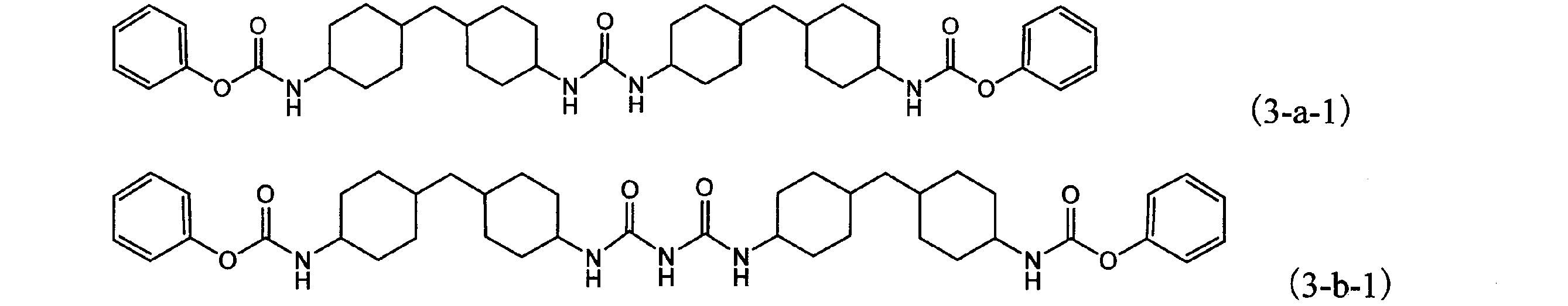
図3に示す装置を使用した。
工程(3-A)で回収した高沸点化合物を含む液相成分50kgを180℃に保持した状態でラインB30を通じて撹拌槽B301に供給した。
撹拌槽B301に水100kgとメタノール50kgを添加して250℃、4.9MPaで均一な溶液とした。該溶液をラインB33を通じて、250℃に加熱され、4.9MPaに加圧された攪拌槽B302に連続的に供給した。
攪拌槽B302で生じた気相成分は、ラインB34を通して、攪拌槽B301に導入した。 Step (3-1): Step of reacting a liquid phase component containing a high boiling point compound with an active hydrogen-containing compound The apparatus shown in FIG. 3 was used.
In a state where 50 kg of the liquid phase component containing the high boiling point compound recovered in the step (3-A) is maintained at 180 ° C., it is supplied to the stirring tank B301 through the line B30.
100 kg of water and 50 kg of methanol were added to the stirring tank B301 to obtain a uniform solution at 250 ° C. and 4.9 MPa. The solution was continuously supplied to a stirring tank B302 which was heated to 250 ° C. and pressurized to 4.9 MPa through a line B33.
The gas phase component generated in the stirring tank B302 was introduced into the stirring tank B301 through the line B34.
工程(3-1)において撹拌槽B301内の気相成分をラインB32を通して凝縮器B303に導入した。導入された気相成分は、凝縮器B303で5℃に冷却し、凝縮液を得た。得られた凝縮液は、ラインB31を通して、撹拌槽B301に戻した。工程(3-1)をおこなっている間、この工程を継続しておこなった。 Step (3-2): Returning the condensate obtained by cooling the gas phase component back into the reactor In the step (3-1), the gas phase component in the stirring tank B301 is condensed via the line B32 to the condenser B303. Introduced to The introduced gas phase component was cooled to 5 ° C. in a condenser B 303 to obtain a condensate. The obtained condensate was returned to the stirring tank B301 through the line B31. This step was continued while performing step (3-1).
工程(3-2)において凝縮されなかった気相成分を保圧弁B304よりガス成分(分析の結果、二酸化炭素が主成分であった)としてラインB36を通して抜き出した。工程(3-1)をおこなっている間、この工程を継続しておこなった。 Step (3-3): The step of discharging the non-condensed gas phase component to the other part of the reactor The gas phase component not condensed in the step (3-2) It extracted through line B36 as carbon was a main component. This step was continued while performing step (3-1).
工程(3-1)において、攪拌槽B302の底部からライン35を経て反応液を貯槽B305に回収した。平均滞留時間は3時間であった。
得られた反応液をガスクロマトグラフィーにて分析したところ、4、4’-ジシクロヘキシルメタンジアミンが含まれていた。 Step (3-4): Step of discharging the reaction solution to the outside of the reactor In step (3-1), the reaction solution was collected in the storage tank B 305 from the bottom of the stirring tank B 302 through the line 35. The average residence time was 3 hours.
The reaction liquid obtained was analyzed by gas chromatography, and it was found that 4,4′-dicyclohexylmethanediamine was contained.
回収した反応液を減圧蒸留し、粗4、4’-ジシクロヘキシルメタンジアミンを回収した。収率は90%であった。 Step (3-5): Step of separating compound (III) The recovered reaction liquid was distilled under reduced pressure to recover crude 4,4′-dicyclohexylmethanediamine. The yield was 90%.
工程(3-5)で回収した粗4、4’-ジシクロヘキシルメタンジアミンを蒸留精製した。
回収した4、4’-ジシクロヘキシルメタンジアミンは純度が99質量%以上(ガスクロマトグラフィーの分析誤差を含む)であった。また、4、4’-ジシクロヘキシルメタンジアミンの総質量に対する金属原子含有量は1000ppm未満、ハロゲン原子含有量は1000ppm未満であった。 Step (3-6): Step of purifying compound (III) The crude 4,4′-dicyclohexylmethanediamine recovered in step (3-5) was purified by distillation.
The recovered 4,4′-dicyclohexylmethanediamine had a purity of 99% by mass or more (including an analysis error of gas chromatography). In addition, the metal atom content relative to the total mass of 4,4′-dicyclohexylmethanediamine was less than 1000 ppm, and the halogen atom content was less than 1000 ppm.
工程(4-A):化合物(I)の製造で副生する高沸点化合物を含む液相成分を得る工程
(カルバメートの製造)
図16に示す装置を使用し、フェノールを50kg、炭酸ジフェニルを38kg、1,6-ヘキサメチレンジアミンを8.2kg使用した以外は実施例3の「カルバメートの製造」と同様の方法をおこない反応液を得た。該反応液を液体クロマトグラフィーで分析したところ、下記式(4-1)で表されるカルバメートが1,6-ヘキサメチレンジアミンに対して収率95%で生成していた。 Example 4
Step (4-A): Step of obtaining a liquid phase component containing a high boiling point compound by-produced in the production of compound (I) (production of carbamate)
A reaction solution was prepared in the same manner as in "Preparation of carbamate" in Example 3 except that 50 kg of phenol, 38 kg of diphenyl carbonate and 8.2 kg of 1,6-hexamethylenediamine were used using the apparatus shown in FIG. I got The reaction liquid was analyzed by liquid chromatography, and it was found that the carbamate represented by the following formula (4-1) was produced at a yield of 95% with respect to 1,6-hexamethylenediamine.

図17に示す装置を使用した。
多段蒸留塔A601にラインA65を通じて4-(α,α-ジメチルベンジル)フェノールを供給し、リボイラーA602で加熱して多段蒸留塔A601を全還流状態とした。ここにラインA61を通じて上記「カルバメートの製造」で得た反応液を供給し、上記式(4-1)で表される化合物のエステル交換反応をおこなった。エステル交換反応で生じたフェノールを含む気相成分をラインA63に通して凝縮器A603に供給した。凝縮器A603にて100℃に冷却して得た凝縮液の一部をラインA64を通じて多段蒸留塔A601に供給し、残りの凝縮液を貯槽A604に回収した。得られた反応液はラインA62を通じて貯槽A605に回収した。
反応液を液体クロマトグラフィーで分析したところ、下記式(4-2)で表される化合物が、式(4-1)に対して収率95%で生成していた。 (Transesterification reaction)
The apparatus shown in FIG. 17 was used.
4- (α, α-dimethylbenzyl) phenol is supplied to the multistage distillation column A601 through the line A65, and is heated by the reboiler A602 to bring the multistage distillation column A601 into a total reflux state. The reaction liquid obtained in the above-mentioned "Production of carbamate" was supplied through line A61 here, and transesterification of the compound represented by the above formula (4-1) was performed. The gas phase component containing phenol generated by the transesterification reaction was supplied through line A63 to the condenser A603. Part of the condensate obtained by cooling to 100 ° C. in the condenser A603 was supplied to the multistage distillation column A601 through the line A64, and the remaining condensate was recovered in the storage tank A604. The obtained reaction solution was collected in storage tank A 605 through line A 62.
The reaction liquid was analyzed by liquid chromatography to find that the compound represented by the following formula (4-2) was produced at a yield of 95% with respect to the formula (4-1).
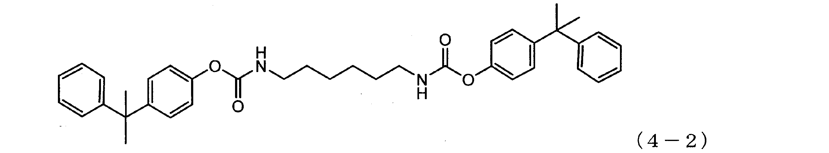
実施例1の「カルバメートの熱分解」と同様の方法をおこない、高沸点化合物を含む液相成分を得た。
当該高沸点化合物を含む液相成分を1H-NMRにて分析したところ、液相成分1kgあたり、カルバメート結合を2.05モル、基(II-1)と基(II-2)を合わせて0.19モル、アロファネート結合とイソシアヌレート結合を合わせて0.48モル、フリース転移末端0.02モルと4-(α,α-ジメチルベンジル)フェノール1.25モルを含有する混合物であった。
当該高沸点化合物を含む液相成分を液体クロマトグラフィーにて分析したところ、該高沸点化合物を含む液相成分は、下記式(4-a-1)で表される化合物および下記式(4-b-1)で表される化合物を含んでいた。 (Thermal decomposition of carbamate)
The same method as “thermal decomposition of carbamate” in Example 1 was performed to obtain a liquid phase component containing a high boiling point compound.
The liquid phase component containing the high-boiling point compound is analyzed by 1 H-NMR to find that 2.05 moles of a carbamate bond per kg of liquid phase component, the group (II-1) and the group (II-2) are combined It was a mixture containing 0.19 mol, 0.48 mol of allophanate bond and isocyanurate bond, 0.02 mol of Fries transition terminal and 1.25 mol of 4- (α, α-dimethylbenzyl) phenol.
When the liquid phase component containing the said high boiling point compound is analyzed by liquid chromatography, the liquid phase component containing this high boiling point compound is a compound represented by the following formula (4-a-1) and the following formula (4- It contained the compound represented by b-1).

図4に示す装置を使用した。
前記工程(4-A)で回収した高沸点化合物を含む液相成分50kgを180℃に保持した状態でラインB40を通じて280℃に加熱し、6.7MPaに加圧された押出機B401に供給した。
押出機B401に、水を、高沸点化合物を含む液相成分50kgに対して100kgの割合で連続的に添加した。 Step (4-1): Step of reacting a liquid phase component containing a high boiling point compound with an active hydrogen-containing compound The apparatus shown in FIG. 4 was used.
50 kg of the liquid phase component containing the high boiling point compound recovered in the step (4-A) was heated to 280 ° C. through the line B 40 while being maintained at 180 ° C. and supplied to the extruder B 401 pressurized at 6.7 MPa .
Water was continuously added to the extruder B401 at a rate of 100 kg based on 50 kg of the liquid phase component containing the high boiling point compound.
工程(4-1)において押出機B401の気相成分を押出機B401が具備するベント口B402からライン41を通じて抜出し、凝縮器B405に導入した。導入された気相成分は、凝縮器B405で冷却され、凝縮液を得た。得られた凝縮液は、ラインB43を通して押出機B401に戻した。工程(4-1)をおこなっている間、この工程を継続しておこなった。 Step (4-2): returning the condensate obtained by cooling the gas phase component back into the reactor Step (4-1) in which the gas phase component of the extruder B 401 is included in the extruder B 401 It extracted from the mouth B402 through the line 41, and introduced it into the condenser B405. The introduced gas phase component was cooled in a condenser B 405 to obtain a condensate. The resulting condensate was returned to extruder B401 through line B43. During the step (4-1), this step was continued.
工程(4-2)において凝縮されなかった気相成分を保圧弁B404よりガス成分(分析の結果、二酸化炭素が主成分であった)としてラインB44を通して抜き出した。工程(4-1)をおこなっている間、この工程を継続しておこなった。 Step (4-3): The step of discharging the non-condensed gas phase component to the other part of the reactor The gas phase component not condensed in the step (4-2) It extracted through line B44 as carbon was a main component. During the step (4-1), this step was continued.
工程(4-1)において、押出機401の吐出口からライン42を経て保圧弁B403により反応液を貯槽B406に回収した。
反応液をガスクロマトグラフィーにて分析したところ、1,6-ヘキサメチレンジアミンが含まれていた。 Step (4-4): Step of discharging the reaction liquid out of the reactor In step (4-1), the reaction liquid was collected into the storage tank B406 by the pressure holding valve B403 from the discharge port of the extruder 401 through the line.
The reaction mixture was analyzed by gas chromatography to find that it contained 1,6-hexamethylenediamine.
回収した反応液を減圧蒸留し、粗1,6-ヘキサメチレンジアミンを回収した。収率は78%であった。 Step (4-5): Step of separating compound (III) The recovered reaction liquid was distilled under reduced pressure to recover
工程(4-5)で回収した粗1,6-ヘキサメチレンジアミンを蒸留精製した。回収した1,6-ヘキサメチレンジアミンは純度が99質量%以上(ガスクロマトグラフィーの分析誤差を含む)であった。また、1,6-ヘキサメチレンジアミンの総質量に対する金属原子含有量は1000ppm未満、ハロゲン原子含有量は1000ppm未満であった。 Step (4-6): Step of purifying compound (III) The
工程(4-5)で、1,6-ヘキサメチレンジアミンを回収した後の残留液を減圧蒸留し、粗4-(α,α-ジメチルベンジル)フェノールを回収した。収率は74%であった。 Step (4-7): Step of separating compound (V) The remaining liquid after recovering 1,6-hexamethylenediamine in step (4-5) is distilled under reduced pressure to obtain crude 4- (α, α- Dimethylbenzyl) phenol was recovered. The yield was 74%.
工程(1-7)で回収した粗4-(α,α-ジメチルベンジル)フェノールを蒸留精製した。4-(α,α-ジメチルベンジル)フェノールは純度が99質量%以上(ガスクロマトグラフィーの分析誤差を含む)であった。また、4-(α,α-ジメチルベンジル)フェノールの総質量に対する金属原子含有量は1000ppm未満、ハロゲン原子含有量は1000ppm未満であった。 Step (4-8): Step of purifying compound (V) The crude 4- (α, α-dimethylbenzyl) phenol recovered in step (1-7) was purified by distillation. 4- (α, α-dimethylbenzyl) phenol had a purity of 99% by mass or more (including analysis error of gas chromatography). In addition, the metal atom content relative to the total mass of 4- (α, α-dimethylbenzyl) phenol was less than 1000 ppm, and the halogen atom content was less than 1000 ppm.
工程(5-A):化合物(I)の製造で副生する高沸点化合物を含む液相成分を得る工程
(ウレイド基を有する化合物の製造)
図18に示す装置を使用した。
尿素10.3kg、4-(1,1,3,3-テトラメチルブチル)フェノール261.9kgを、ラインA70を通じて撹拌槽A701に供給した。130℃で均一溶液とした後、2,4-トルエンジアミン9.8kgを添加し5時間撹拌し、反応液を、ライン71を通じて貯槽702に回収した。
該反応液を液体クロマトグラフィーで分析したところ、下記式(5-1)で表される化合物が、2,4-トルエンジアミンに対して収率90%で生成していた。 [Example 5]
Step (5-A): Step of obtaining a liquid phase component containing a high boiling point compound by-produced in the production of compound (I) (production of a compound having a ureido group)
The apparatus shown in FIG. 18 was used.
10.3 kg of urea and 261.9 kg of 4- (1,1,3,3-tetramethylbutyl) phenol were fed to a stirring tank A701 through a line A70. After making a homogeneous solution at 130 ° C., 9.8 kg of 2,4-toluenediamine was added and the mixture was stirred for 5 hours, and the reaction solution was recovered through line 71 into storage tank 702.
The reaction liquid was analyzed by liquid chromatography to find that the compound represented by the following formula (5-1) was produced in 90% yield to 2,4-toluenediamine.

上記「ウレイド基を有する化合物の製造」において得た反応液を90kg/HrでラインA1より連続多段蒸留塔A101に供給した以外は、実施例1の「カルバメートの製造」と同様の方法をおこなった。 (Production of carbamate)
The same method as in “Production of Carbamate” in Example 1 was carried out except that the reaction liquid obtained in “Production of compound having ureido group” was supplied to continuous multistage distillation column A 101 from line A1 at 90 kg / Hr. .
実施例1の「カルバメートの熱分解」と同様の方法をおこない、高沸点化合物を含む液相成分を得た。
得られた液相成分の150℃における粘度は、82mPa・sであった。
該高沸点化合物を含む液相成分を1H-NMRにて分析したところ、液相成分1kgあたり、カルバメート結合を1.33モル、式(II-1)で表される結合と式(II-2)で表される結合を合わせて0.10モル、アロファネート結合とイソシアヌレート結合を合わせて0.10モル、フリース転位末端を0.16モルを含んでいた。
該高沸点化合物を含む液相成分を液体クロマトグラフィーにて分析したところ、該高沸点化合物を含む液相成分は、下記式(5-a-1)で表される化合物、および下記式(5-b-1)で表される化合物を含み、4-(1,1,3,3-テトラメチルブチル)フェノールを42質量%含んでいた。 (Thermal decomposition of carbamate)
The same method as “thermal decomposition of carbamate” in Example 1 was performed to obtain a liquid phase component containing a high boiling point compound.
The viscosity at 150 ° C. of the obtained liquid phase component was 82 mPa · s.
The liquid phase component containing the high-boiling point compound is analyzed by 1 H-NMR to find that 1.33 moles of a carbamate bond per kg of the liquid phase component, the bond represented by the formula (II-1) and the formula (II-) The combined bonds represented by 2) contained 0.10 moles, the combined allophanate bonds and isocyanurate bonds contained 0.10 moles, and the Fleece rearrangement end 0.16 moles.
When the liquid phase component containing the high boiling point compound is analyzed by liquid chromatography, the liquid phase component containing the high boiling point compound is a compound represented by the following formula (5-a-1), and the following formula (5) It contained 42% by mass of 4- (1,1,3,3-tetramethylbutyl) phenol including the compound represented by -b-1).
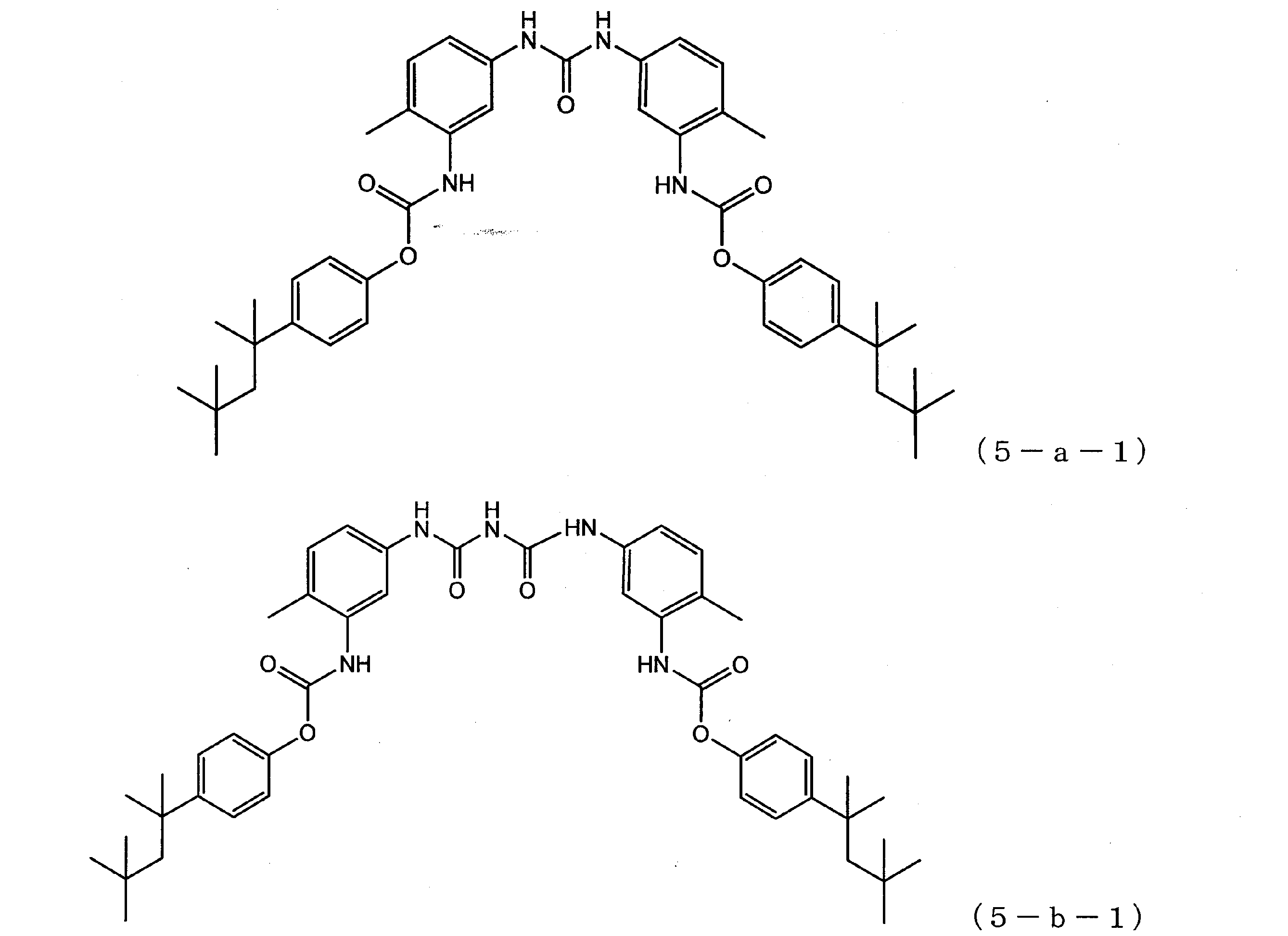
図5に示す装置を使用した。
工程(5-A)で回収した高沸点化合物を含む液相成分50kgを180℃に保持した状態でラインB50を通じて280℃に加熱し、6.7MPaに加圧された押出機B501に供給した。
押出機B501に、水を、高沸点化合物を含む液相成分50kgに対して100kgの割合で連続的に添加した。 Step (5-1) Step of reacting a liquid phase component containing a high boiling point compound with an active hydrogen-containing compound The apparatus shown in FIG. 5 was used.
50 kg of the liquid phase component containing the high boiling point compound recovered in the step (5-A) was heated to 280 ° C. through the line B 50 while being maintained at 180 ° C., and was supplied to the extruder B 501 pressurized at 6.7 MPa.
Water was continuously added to the extruder B501 at a rate of 100 kg based on 50 kg of the liquid phase component containing the high boiling point compound.
工程(5-1)において押出機B501にて生じた気相成分を、押出機B501が具備するベント口B502からライン51を通じて抜出し、凝縮器B506に導入した。導入された気相成分は、凝縮器B506で10℃に冷却され、凝縮液を得た。得られた凝縮液は、ラインB53を通して、押出機B501に戻した。工程(5-1)をおこなっている間、この工程を継続しておこなった。 Step (5-2): Returning the condensate obtained by cooling the gas phase component back into the reactor The gas phase component produced by the extruder B501 in the step (5-1) is an extruder B501. It extracted from the vent port B502 equipped with through line 51, and introduced it into condenser B506. The introduced gas phase component was cooled to 10 ° C. in a condenser B 506 to obtain a condensate. The obtained condensate was returned to extruder B501 through line B53. This step was continued while performing step (5-1).
工程(5-2)において凝縮されなかった気相成分を保圧弁B504よりガス成分(分析の結果、二酸化炭素が主成分であった)としてラインB54を通して抜き出した。工程(5-1)をおこなっている間、この工程を継続しておこなった。 Step (5-3): The step of discharging the non-condensed gas phase component out of the reactor Other than the above-mentioned reactor The gas phase component not condensed in the step (5-2) It extracted through line B54 as carbon was a main component. This step was continued while performing step (5-1).
工程(5-1)において、押出機B501の吐出部に具備する受器B505に回収した反応液を、ラインB55を経て貯槽B507に回収した。
回収された反応液をガスクロマトグラフィーで分析したところ、2,4-トルエンジアミンが含まれていた。 Step (5-4): Step of discharging the reaction liquid to the outside of the reactor In Step (5-1), the reaction liquid collected in the receiver B505 provided in the discharge part of the extruder B501 is stored via the line B55. It collected to B507.
The recovered reaction solution was analyzed by gas chromatography to find that it contained 2,4-toluenediamine.
回収した反応液を減圧蒸留し、粗2,4-トルエンジアミンを回収した。収率は73%であった。 Step (5-5): Step of separating compound (III) The recovered reaction liquid was distilled under reduced pressure to recover crude 2,4-toluenediamine. The yield was 73%.
工程(5-5)で回収した粗2,4-トルエンジアミンを蒸留精製した。回収した2,4-トルエンジアミンは純度が99質量%以上(ガスクロマトグラフィーの分析誤差を含む)であった。また、2,4-トルエンジアミンの総質量に対する金属原子含有量は1000ppm未満、ハロゲン原子含有量は1000ppm未満であった。 Step (5-6): Step of purifying compound (III) The crude 2,4-toluenediamine recovered in step (5-5) was purified by distillation. The recovered 2,4-toluenediamine had a purity of 99% by mass or more (including an analysis error of gas chromatography). In addition, the metal atom content relative to the total mass of 2,4-toluenediamine was less than 1000 ppm, and the halogen atom content was less than 1000 ppm.
工程(5-5)で、化合物(III)を回収した後の残留液を減圧蒸留し、粗4-(1,1,3,3-テトラメチルブチル)フェノールを回収した。収率は78%であった。 Step (5-7): Step of separating compound (V) The remaining liquid after recovering compound (III) in step (5-5) is distilled under reduced pressure to obtain crude 4- (1,1,3,3,3 -Tetramethylbutyl) phenol was recovered. The yield was 78%.
工程(5-7)で回収した粗4-(1,1,3,3-テトラメチルブチル)フェノールを蒸留精製した。回収した4-(1,1,3,3-テトラメチルブチル)フェノールは純度が99質量%以上(ガスクロマトグラフィーの分析誤差を含む)であった。また、4-(1,1,3,3-テトラメチルブチル)フェノールの総質量に対する金属原子含有量は1000ppm未満、ハロゲン原子含有量は1000ppm未満であった。 Step (5-8): Step of purifying compound (V) The crude 4- (1,1,3,3-tetramethylbutyl) phenol recovered in step (5-7) was purified by distillation. The recovered 4- (1,1,3,3-tetramethylbutyl) phenol had a purity of 99% by mass or more (including an analysis error of gas chromatography). In addition, the metal atom content relative to the total mass of 4- (1,1,3,3-tetramethylbutyl) phenol was less than 1000 ppm, and the halogen atom content was less than 1000 ppm.
工程(6-A):化合物(I)の製造で副生する高沸点化合物を含む液相成分を得る工程
1,5-ペンタメチレンジアミンとホスゲンとの反応により2,4-トルエンジイソシアネートを製造する際に生成する蒸留残渣(溶融物)を得た。これを、高沸点化合物を含有する組成物として使用した。
該高沸点化合物を含む液相成分は、サンプル調製時の不溶成分が多く、フィルターでろ過して可溶成分のみを1H-NMRで分析した結果、基(II-1)及び基(II-2)を有する化合物の存在が確認された。 [Example 6]
Step (6-A): Step of obtaining a liquid phase component containing a high-boiling point compound by-produced in the production of compound (I): 2,4-toluene diisocyanate is produced by the reaction of 1,5-pentamethylenediamine and phosgene The distillation residue (melt) produced during the reaction was obtained. This was used as a composition containing high boiling point compounds.
The liquid phase component containing the high boiling point compound has many insoluble components at the time of sample preparation, and it is filtered through a filter and only soluble components are analyzed by 1 H-NMR, the result is group (II-1) and group (II-) The presence of the compound having 2) was confirmed.
図6に示す装置を使用した。
工程(6-A)の蒸留残渣50kgと300℃に保持した状態で、水50kgとエタノール30kgを混合し、該混合液を、ラインB60を通じ薄膜蒸発機B602に供給した。
供給された混合液は、6.7MPaで、280℃に加熱された加熱蒸発面B601に、薄膜状に展開された。 Process (6-1):
The apparatus shown in FIG. 6 was used.
In a state of holding 50 kg of the distillation residue of step (6-A) and 300 ° C., 50 kg of water and 30 kg of ethanol were mixed, and the mixture was supplied to thin-film evaporator B602 through line B60.
The supplied mixed solution was developed in a thin film form on a heating evaporation surface B601 heated to 280 ° C. at 6.7 MPa.
工程(6-1)において、加熱蒸発面B601における分解反応により副生した気相成分は、ラインB64から抜き出され、凝縮器B604に導入された。凝縮器B604で10℃に冷却されて得られた凝縮液は、ラインB63を通して薄膜蒸発機B602に戻された。工程(6-1)をおこなっている間、この工程を継続しておこなった。 Step (6-2): Step of returning the condensate obtained by cooling the gas phase component back into the reactor In the step (6-1), the gas phase component by-produced by the decomposition reaction on the heating evaporation surface B601 Were withdrawn from line B64 and introduced into condenser B604. The condensate obtained by cooling to 10 ° C. in the condenser B604 was returned to the thin film evaporator B602 through the line B63. This step was continued while performing step (6-1).
工程(6-2)において凝縮されなかった気相成分を保圧弁B606よりガス成分(分析の結果、二酸化炭素が主成分であった)としてラインB61を通して抜き出した。工程(6-1)をおこなっている間、この工程を継続しておこなった。 Step (6-3): The step of discharging the non-condensed gas phase component out of the reactor Other than the step (6-2) The gas phase component not condensed in the step (6-2) It extracted through line B61 as carbon was a main component. This step was continued while performing step (6-1).
工程(6-1)において、加熱蒸発面B601における分解反応により生じた反応液は、加熱蒸発面B601の表面を伝い、回収部B603に回収された。回収部B603に回収された成分はラインB62を経て貯槽B605に回収された。
回収された反応液をガスクロマトグラフィーで分析したところ、2,4-トルエンジアミンが含まれていた。 Step (6-4): Step of discharging the reaction liquid to the outside of the reactor In Step (6-1), the reaction liquid generated by the decomposition reaction on the heating evaporation surface B601 is transmitted along the surface of the heating evaporation surface B601 and recovered. Part B603 was collected. The components recovered in the recovery unit B 603 are recovered in the storage tank B 605 through the line B 62.
The recovered reaction solution was analyzed by gas chromatography to find that it contained 2,4-toluenediamine.
回収した反応液を減圧蒸留し、粗1,5-ペンタメチレンジアミンを回収した。 Step (6-5): Step of separating compound (III) The recovered reaction liquid was distilled under reduced pressure to recover
工程(6-5)で回収した粗1,5-ペンタメチレンジアミンを蒸留精製した。回収した1,5-ペンタメチレンジアミンは純度が99質量%以上(ガスクロマトグラフィーの分析誤差を含む)であった。また、1,5-ペンタメチレンジアミンの総質量に対する金属原子含有量は1000ppm未満、ハロゲン原子含有量は1000ppm未満であった。 Step (6-6): Step of purifying compound (III) The
工程(7-A):化合物(I)の製造で副生する高沸点化合物を含む液相成分を得る工程
実施例6の工程(6-A)と同様の方法で、1,5-ペンタメチレンジアミンを製造し、高沸点化合物を含有する組成物を回収した。
該高沸点化合物を含む液相成分は、サンプル調製時の不溶成分が多く、フィルターでろ過して可溶分のみを1H-NMRで分析した結果、基(II-1)と基(II-2)を有する化合物の存在が確認された。 [Example 7]
Step (7-A): Step of obtaining liquid phase component containing high-boiling point compound by-produced in production of compound (I) In the same manner as step (6-A) of Example 6, 1,5-pentamethylene The diamine was prepared and the composition containing the high boiling point compound was recovered.
The liquid phase component containing the high-boiling point compound has a large amount of insoluble components at the time of sample preparation, and it is filtered through a filter and only solubles are analyzed by 1 H-NMR. The presence of the compound having 2) was confirmed.
図7に示す装置を使用した。
工程(7-A)の蒸留残渣50kgと300℃に保持した状態で、水50kgと1,5-ペンタメチレンジアミン25kgを混合し、該混合液を、ラインB70を通じ薄膜蒸発機B702に供給した。
供給された混合液は、6.7MPa下で280℃に加熱された加熱蒸発面B701に薄膜状に展開された。気相成分は凝縮器B704にて50℃に冷却し、凝縮された液をラインB73を通して排出した。 Process (7-1):
The apparatus shown in FIG. 7 was used.
50 kg of water and 50 kg of water and 25 kg of 1,5-pentamethylenediamine were mixed while maintaining 50 kg of the distillation residue of step (7-A) at 300 ° C., and the mixture was supplied to thin-film evaporator B702 through line B70.
The supplied mixture was spread in a thin film on a heating evaporation surface B 701 heated to 280 ° C. under 6.7 MPa. The gas phase components were cooled to 50 ° C. in a condenser B704, and the condensed liquid was discharged through a line B73.
工程(7-1)において、反応液を、薄膜蒸発機の底部に設けられた回収部B703に回収後、ラインB72を通して排出した。
排出された反応液をガスクロマトグラフィーで分析したところ、1,5-ペンタメチレンジアミンが含まれていた。 Step (7-2): Step of discharging the reaction solution to the outside of the reactor In step (7-1), the reaction solution is collected in the recovery unit B 703 provided at the bottom of the thin film evaporator, and then discharged through the line B 72 did.
The discharged reaction solution was analyzed by gas chromatography and found to contain 1,5-pentamethylenediamine.
排出された反応液を減圧蒸留し、粗1,5-ペンタメチレンジアミンを回収した。 Step (7-3): Step of separating compound (III) The discharged reaction solution was distilled under reduced pressure to recover
工程(7-3)で回収した粗1,5-ペンタメチレンジアミンを蒸留精製した。回収した1,5-ペンタメチレンジアミンは純度が99質量%以上(ガスクロマトグラフィーの分析誤差を含む)であった。また、1,5-ペンタメチレンジアミンの総質量に対する金属原子含有量は1000ppm未満、ハロゲン原子含有量は1000ppm未満であった。 Step (7-4): Step of purifying compound (III) The
上記実施例1~7に記載の方法を組み合わせて、化合物(I)の製造で副生する高沸点化合物を含む液相成分を得、高沸点化合物を含む液相成分と活性水素含有化合物とを反応器内で反応させる工程(1)、反応器内の気相成分を冷却することにより得られた凝縮液を前記反応器内へ戻す工程(2)、凝縮されなかった気相成分を反応器以外へ排出する工程(3)、反応器内の液相成分を反応器外に排出する工程(4)、化合物(III)を分離する工程(5)、化合物(III)を精製する工程(6)、化合物(V)を分離する工程(7)、及び化合物(V)を生成する工程をおこなった。その結果を表に示した。活性水素化合物として使用した有機第1アミンは、有機第1アミンの収率に含まない。
カルバメートの熱分解を実施例2のカルバメートの熱分解と同様の方法でおこなった実施例8~10、14~17、34、39、43では、ジベンジルエーテルの代わりに下表に示す化合物を使用した。 [Examples 8 to 52]
By combining the methods described in Examples 1 to 7 above, liquid phase components containing high-boiling compounds by-produced in production of compound (I) are obtained, and liquid phase components containing high-boiling compounds and active hydrogen-containing compounds are obtained. Step (1) of reacting in the reactor, step (2) of returning the condensate obtained by cooling the gas phase components in the reactor into the reactor (2), reactor of the gas phase components not condensed Step (3) of discharging to another, step (4) of discharging liquid phase component in the reactor out of the reactor, step (5) of separating compound (III), step of purifying compound (III) (6 ), Step (7) of separating compound (V), and step of producing compound (V). The results are shown in the table. The organic primary amine used as the active hydrogen compound is not included in the yield of the organic primary amine.
In Examples 8-10, 14-17, 34, 39, 43 in which the thermal decomposition of carbamate was carried out in the same manner as the thermal decomposition of carbamate in Example 2, the compounds shown in the table below were used instead of dibenzyl ether. did.
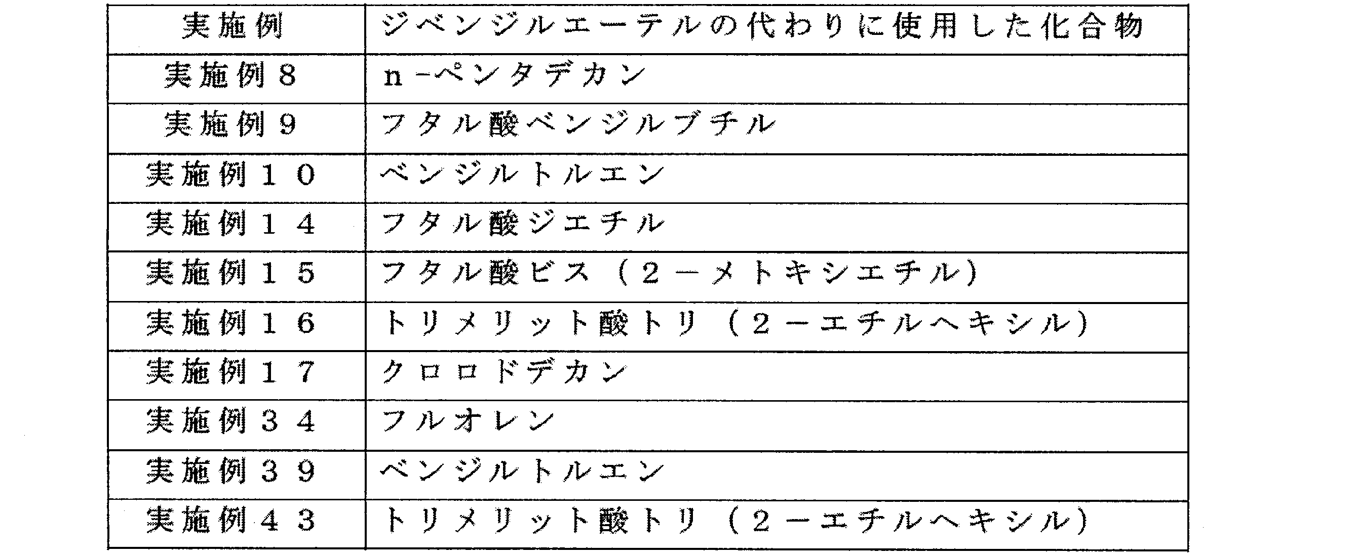

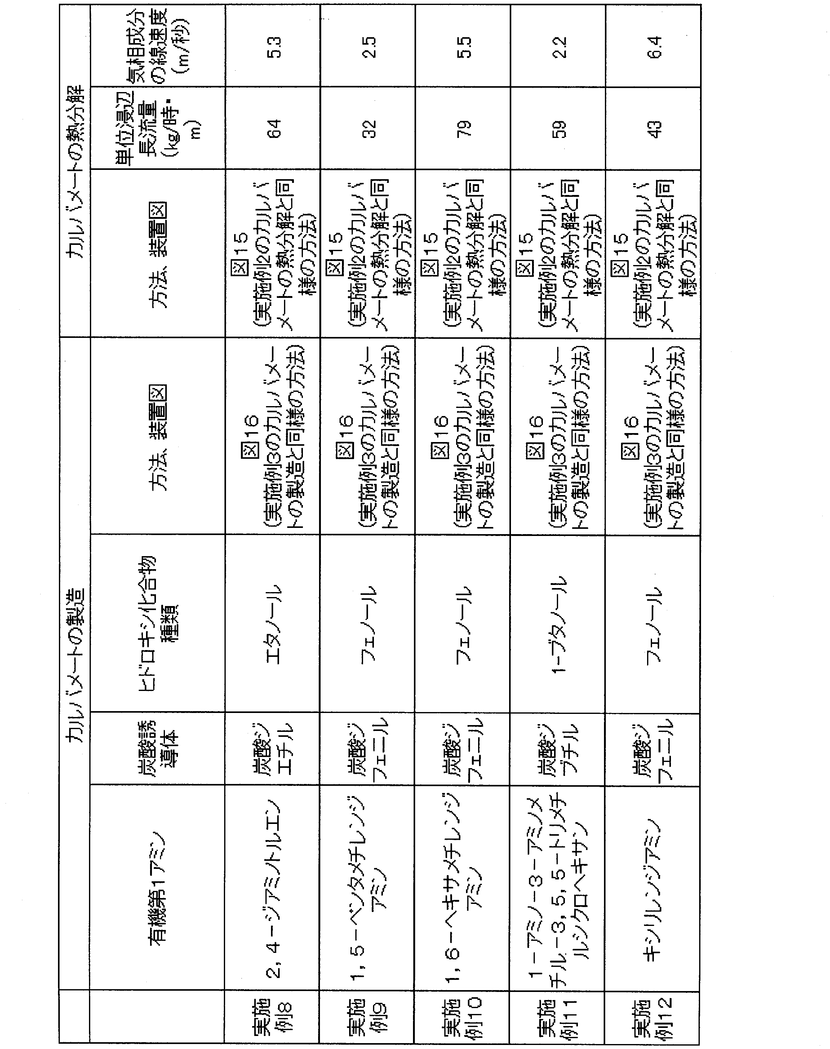

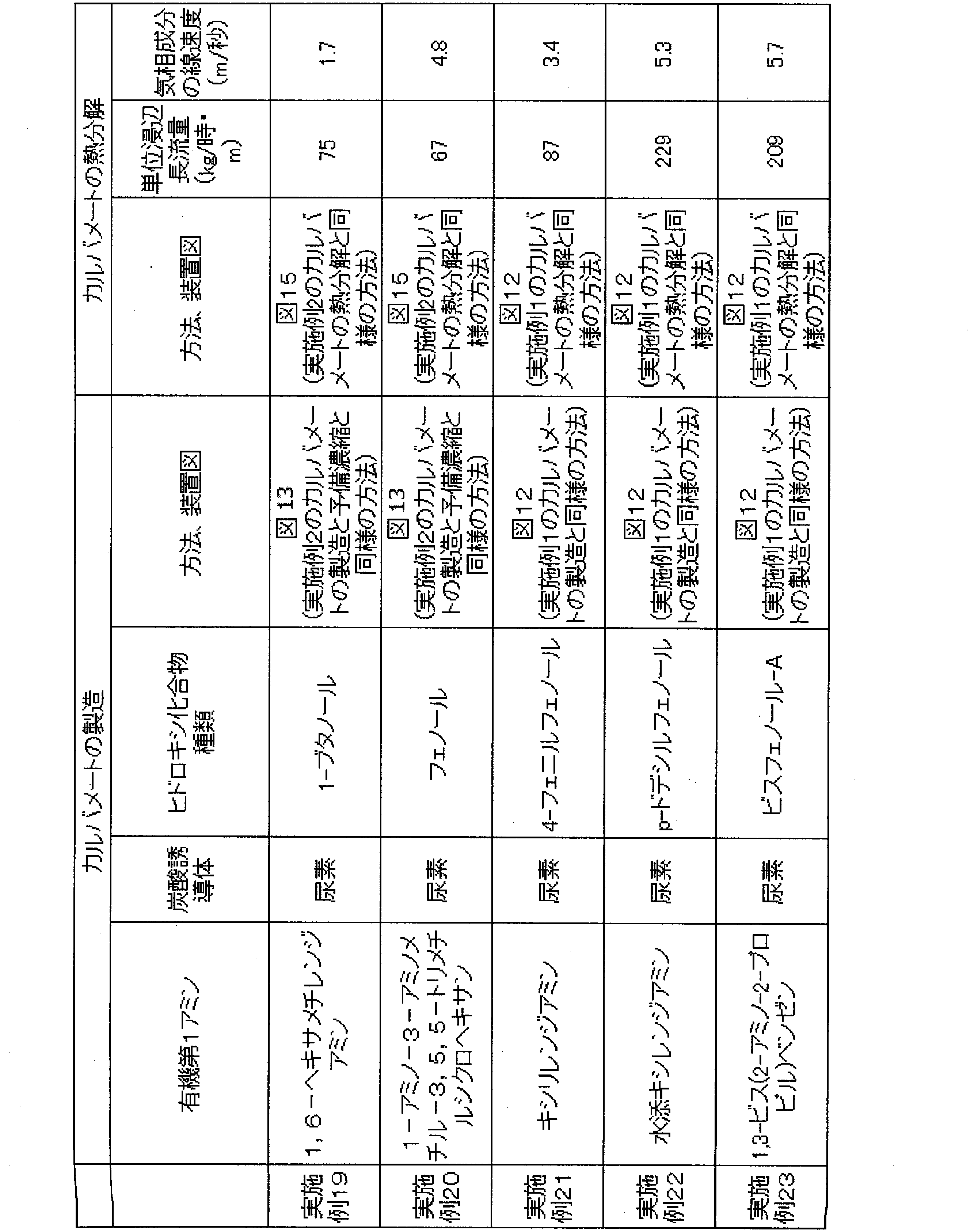
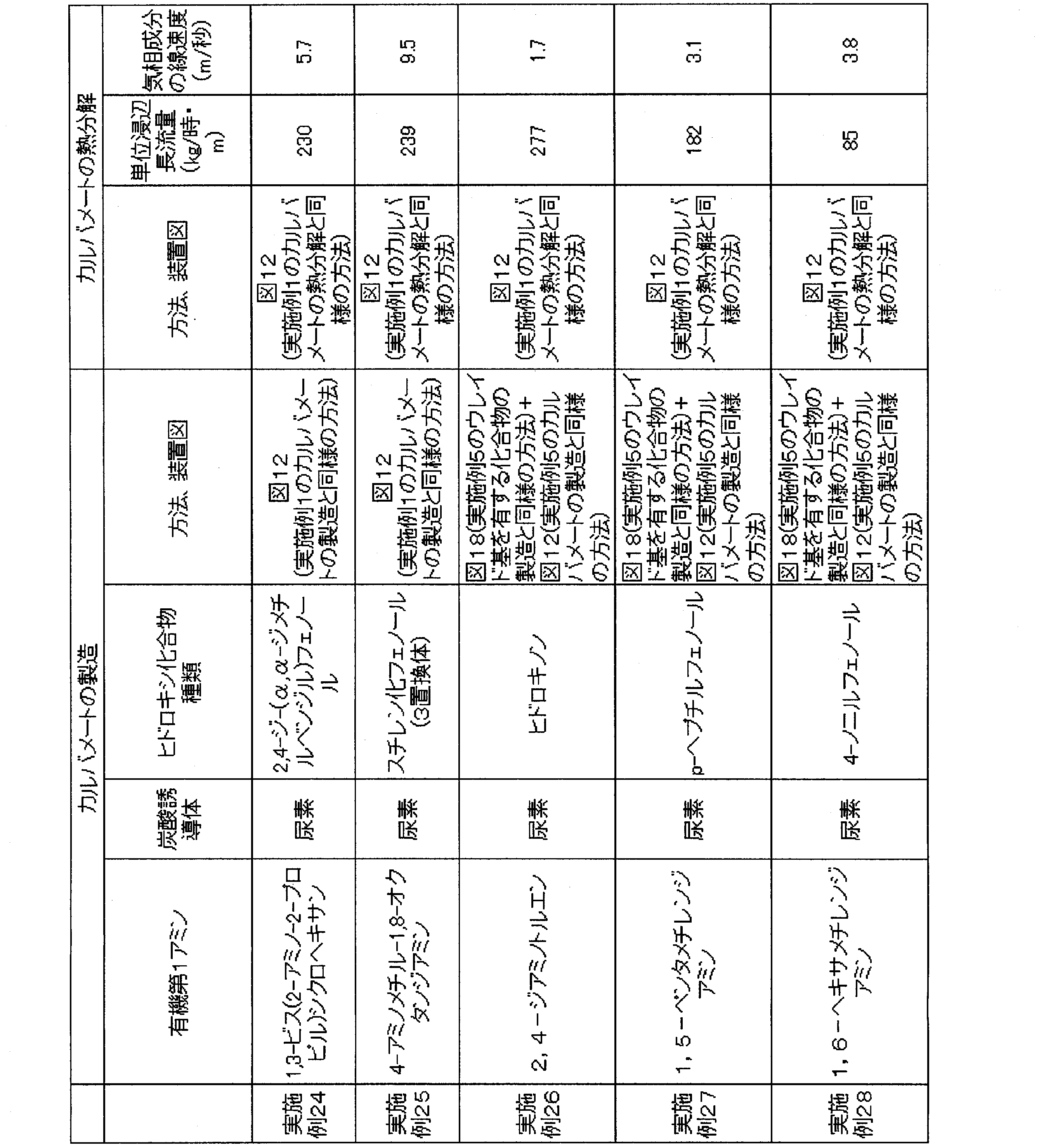

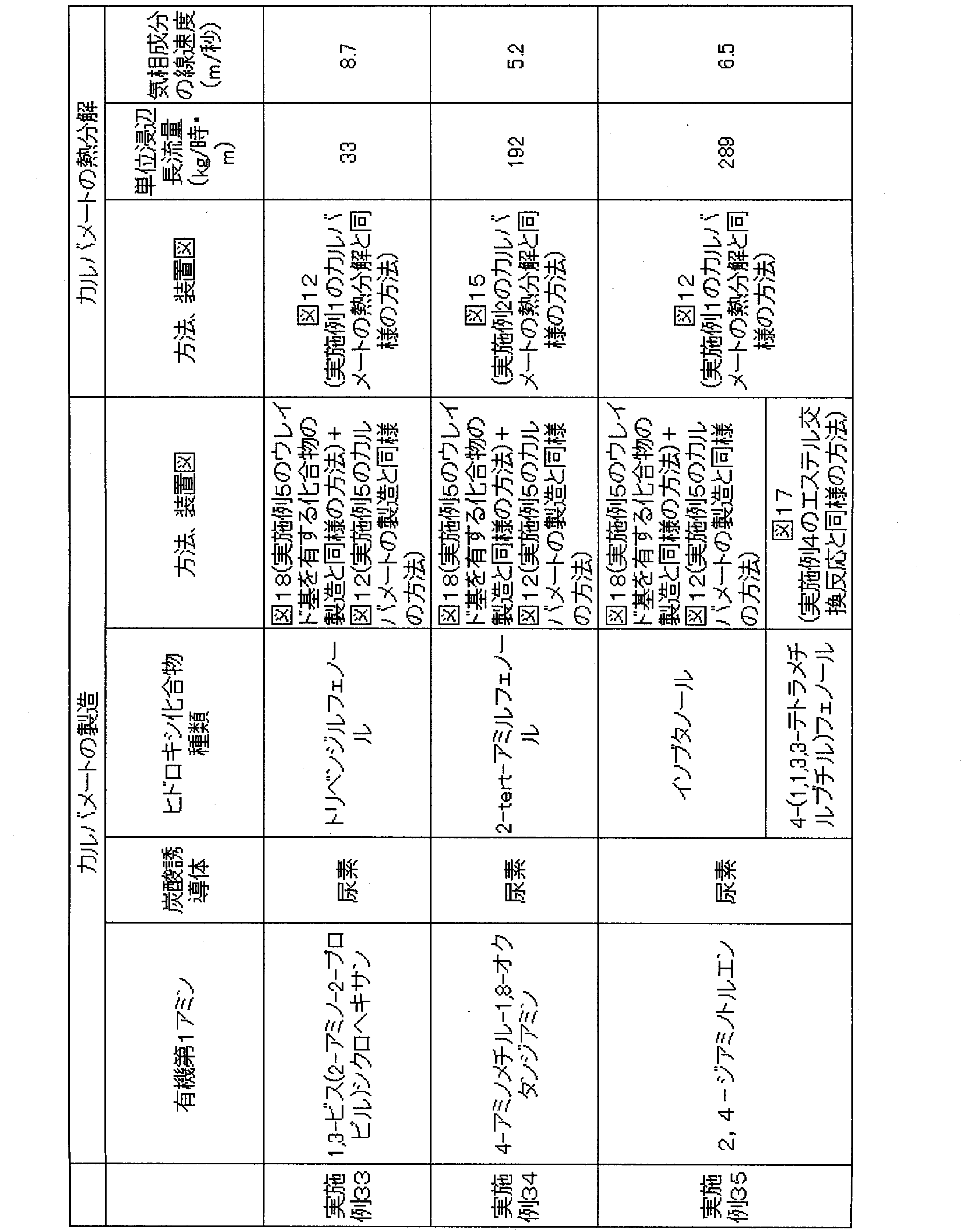
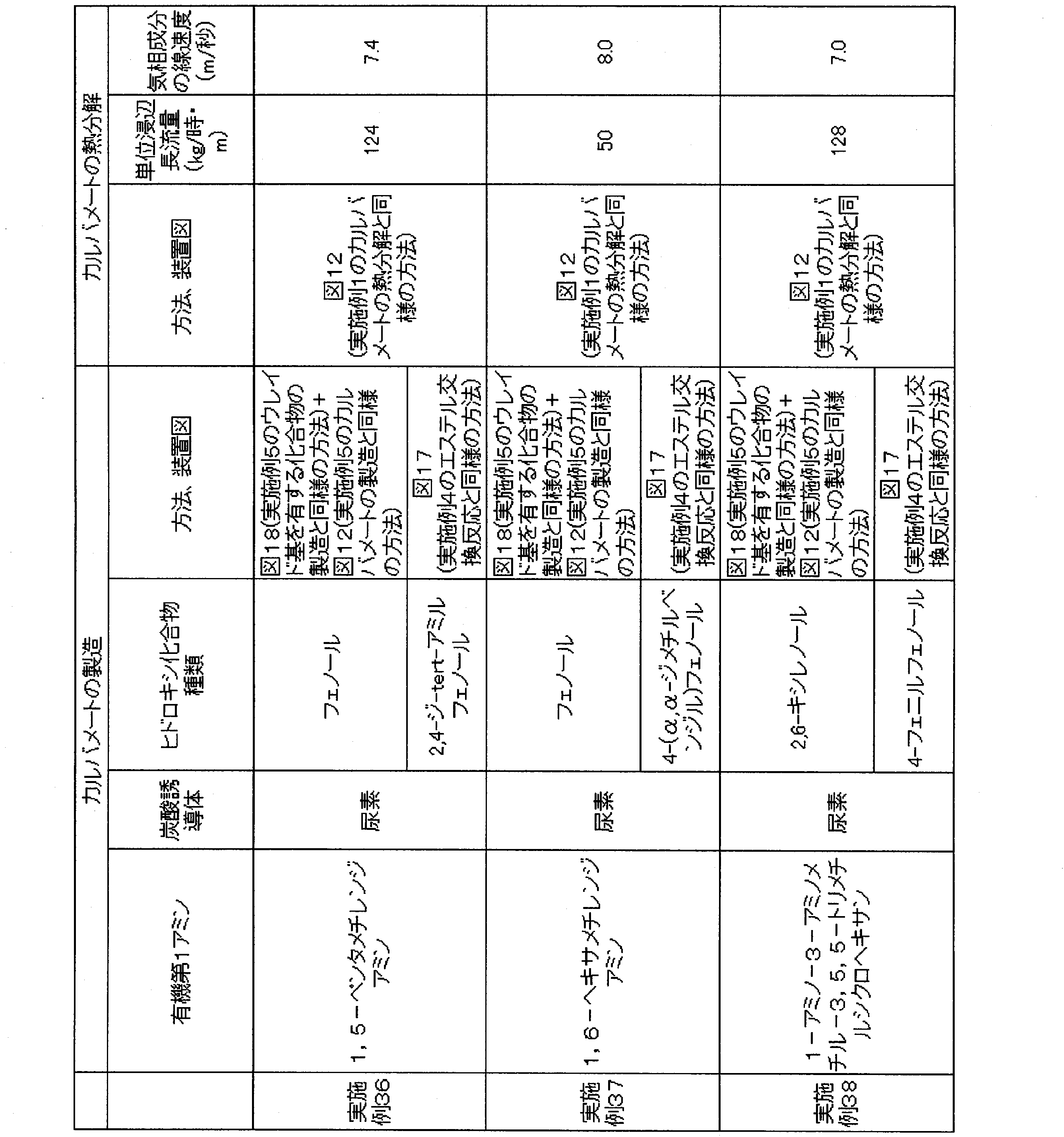
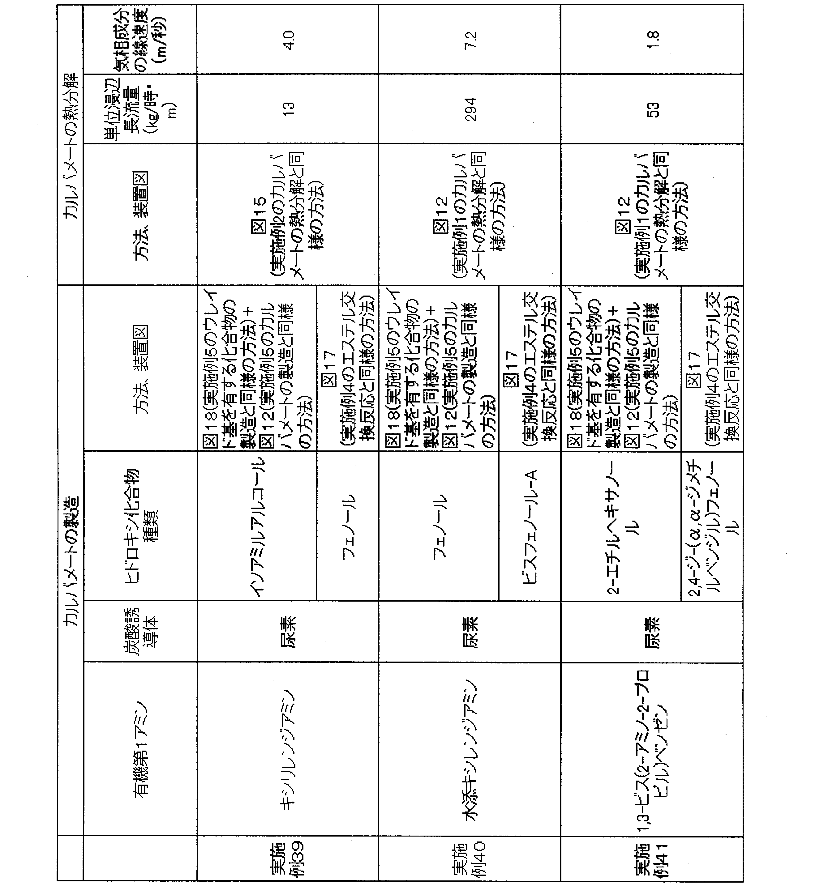

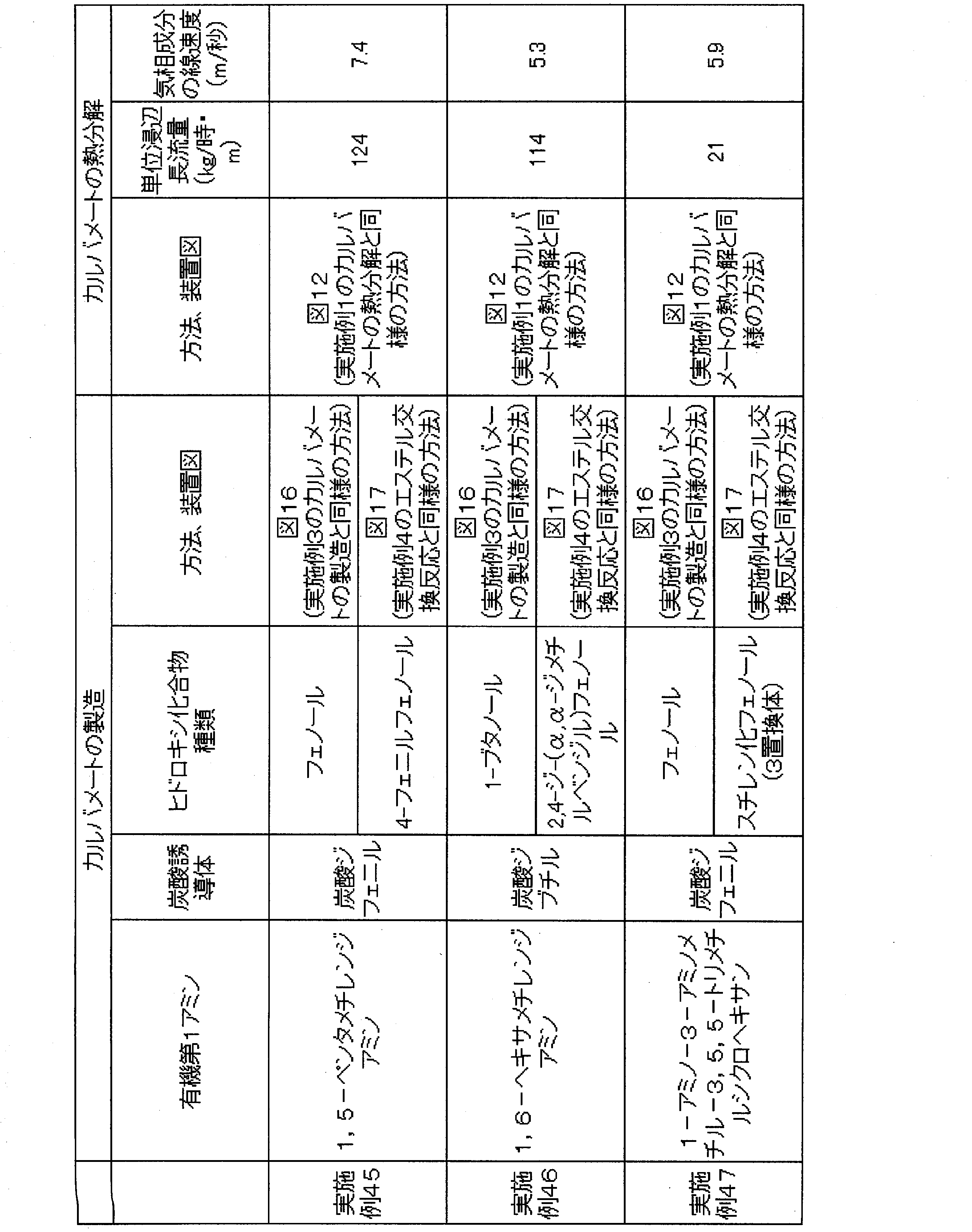

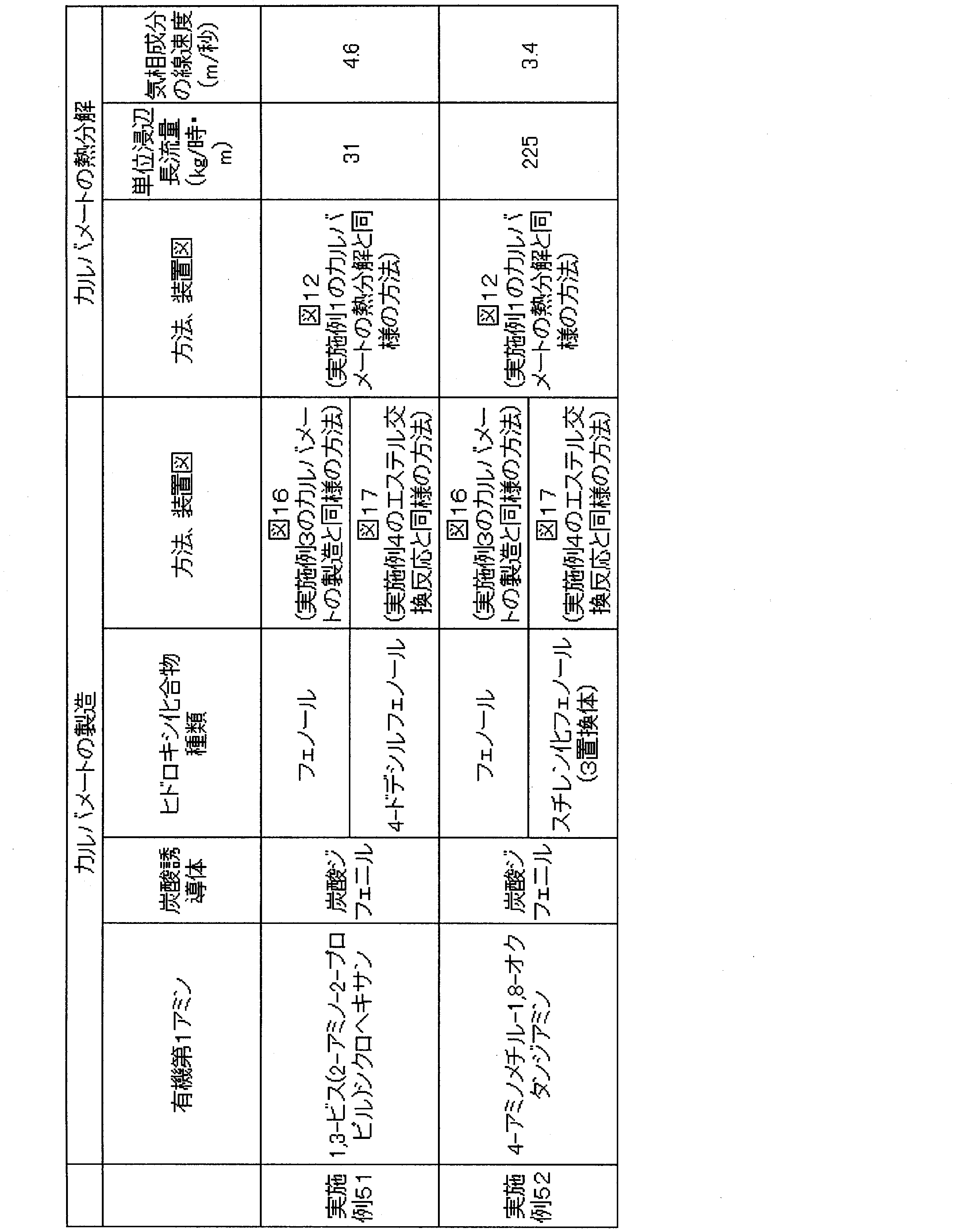

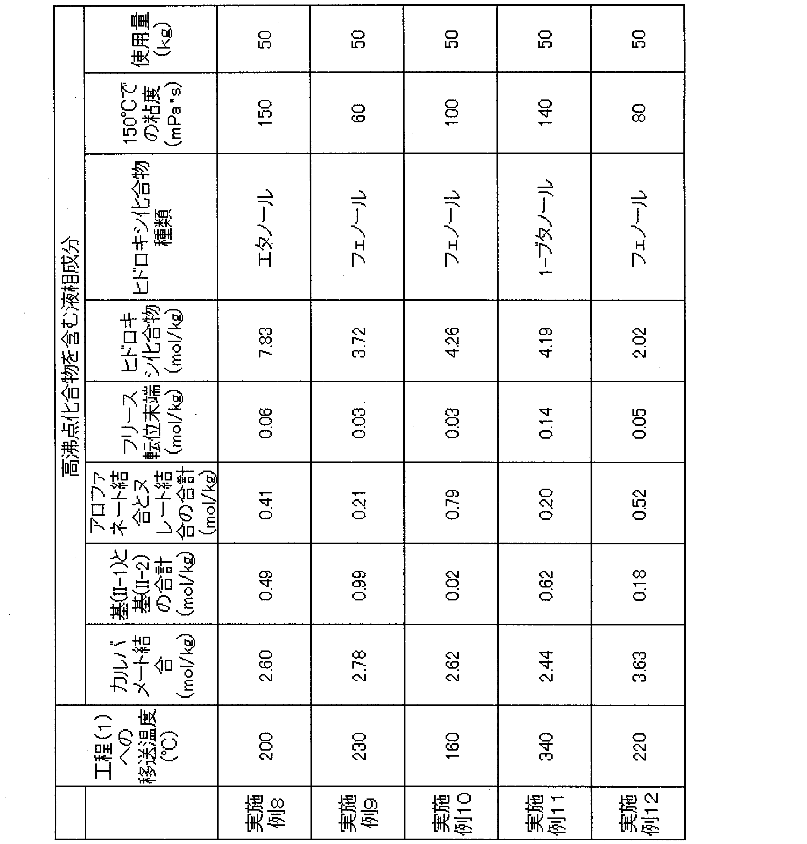
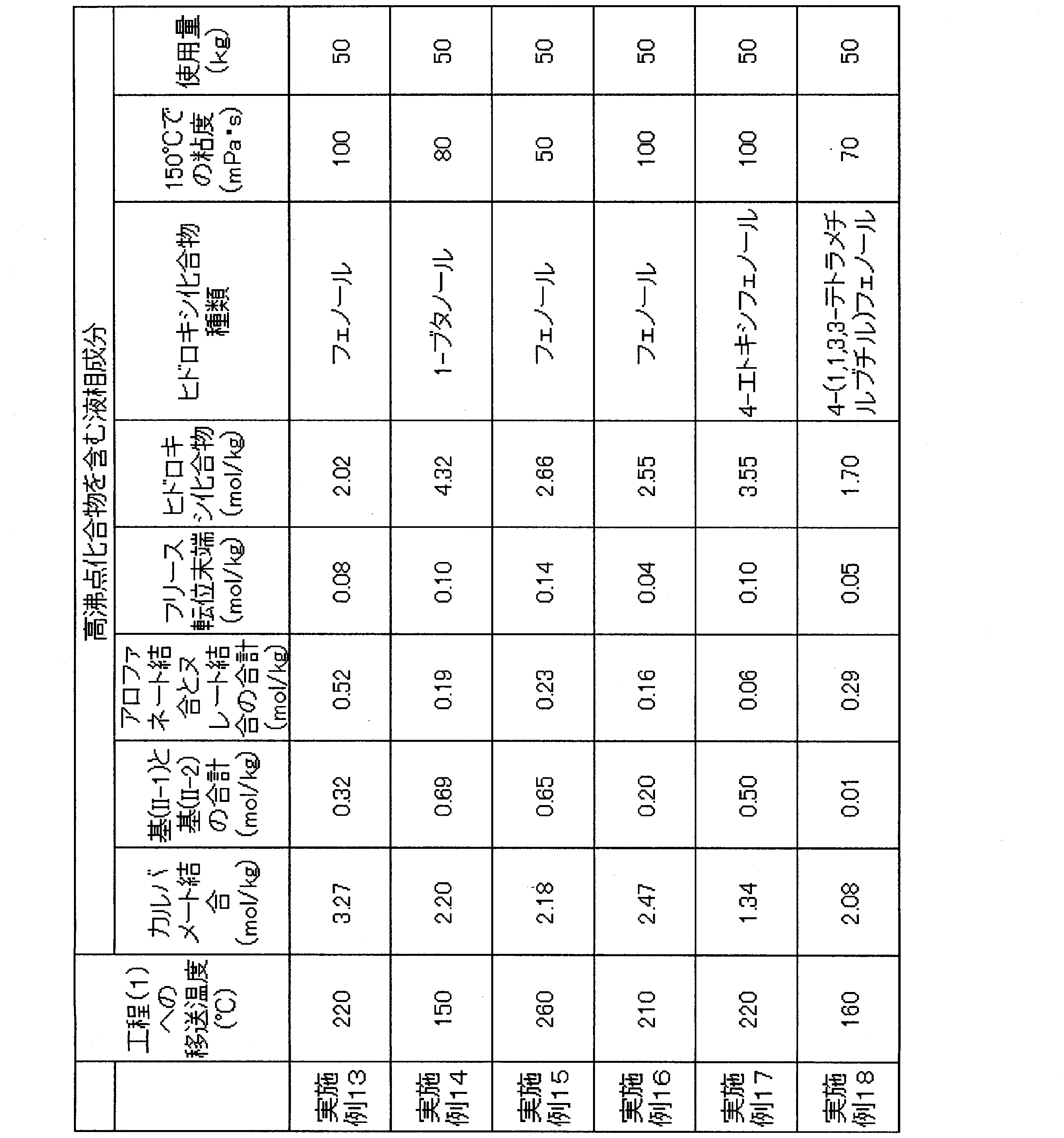
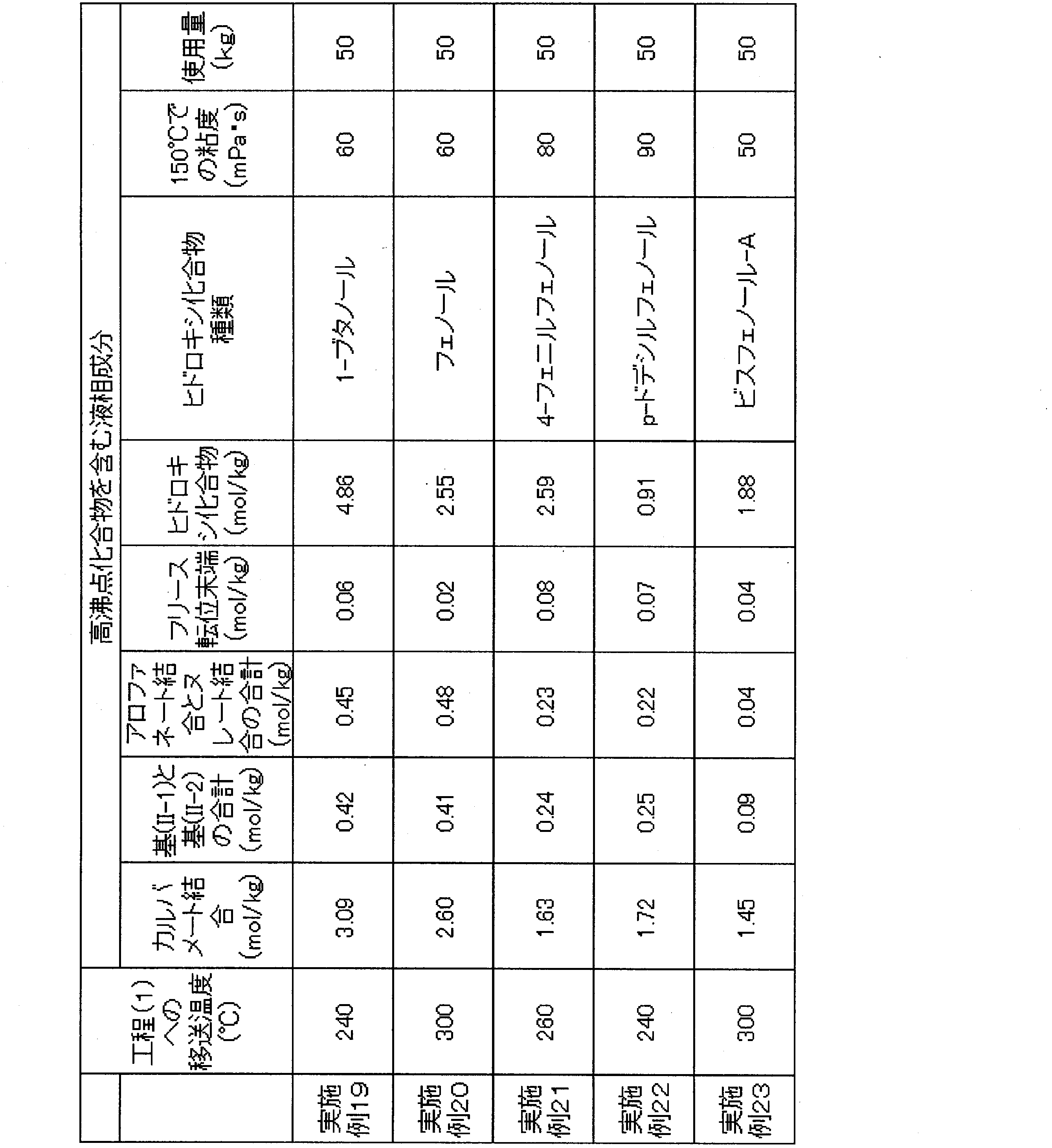
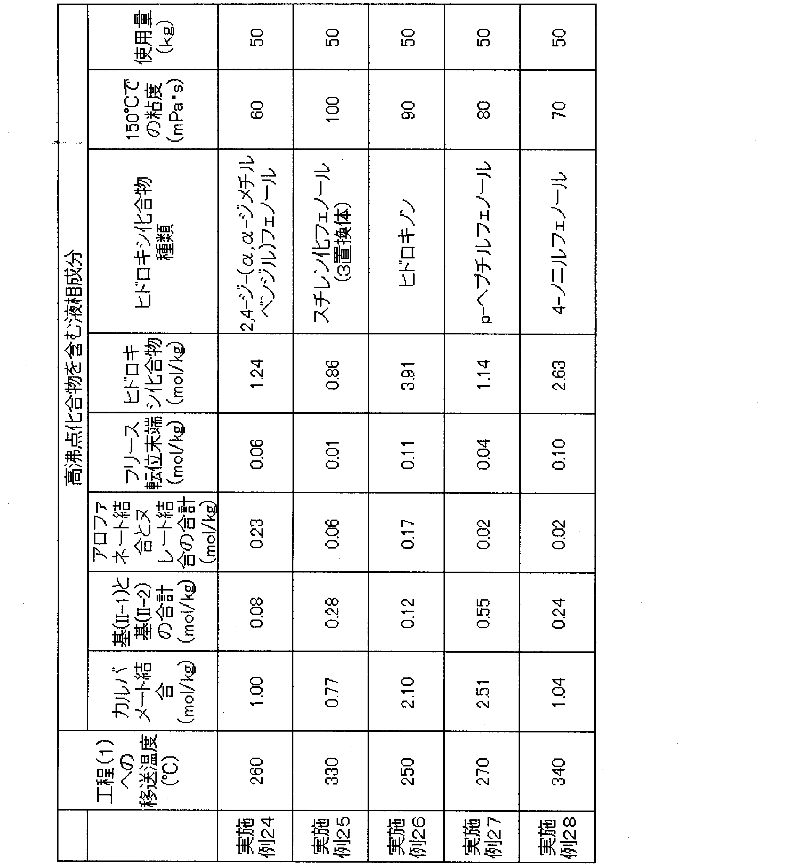
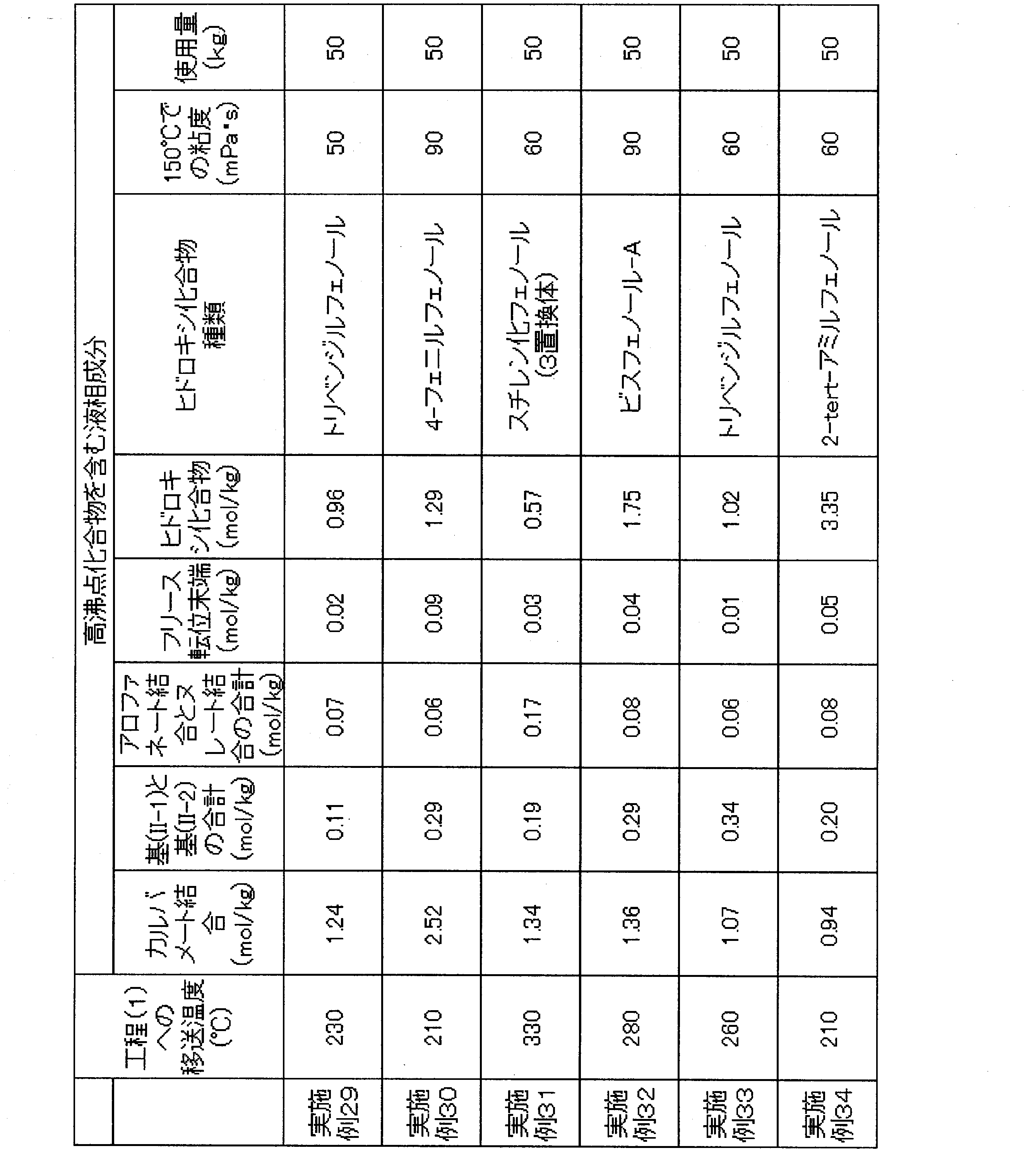

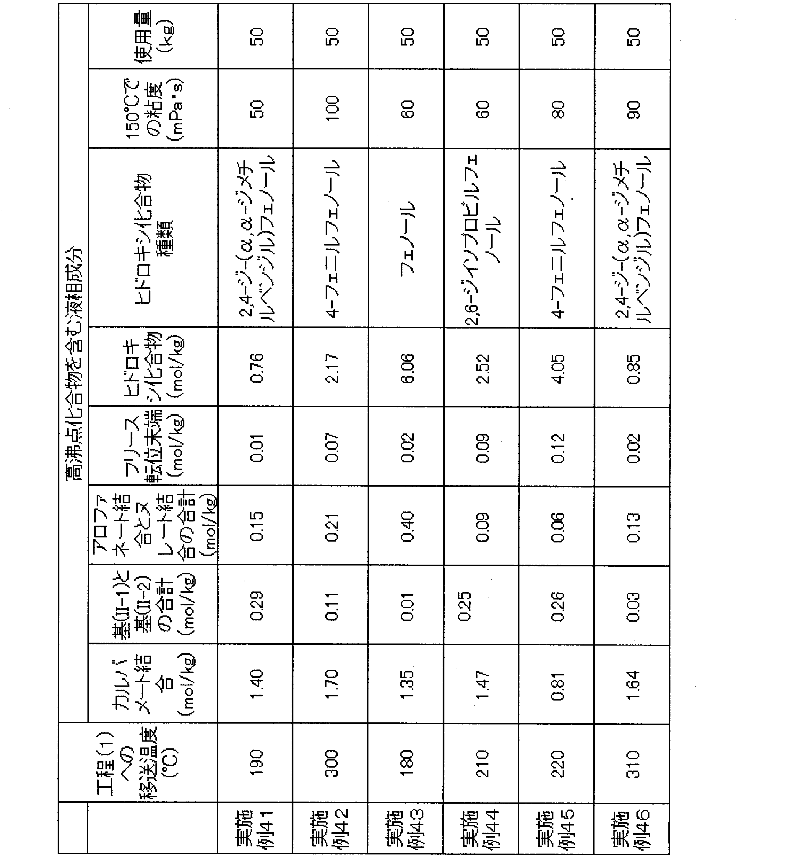
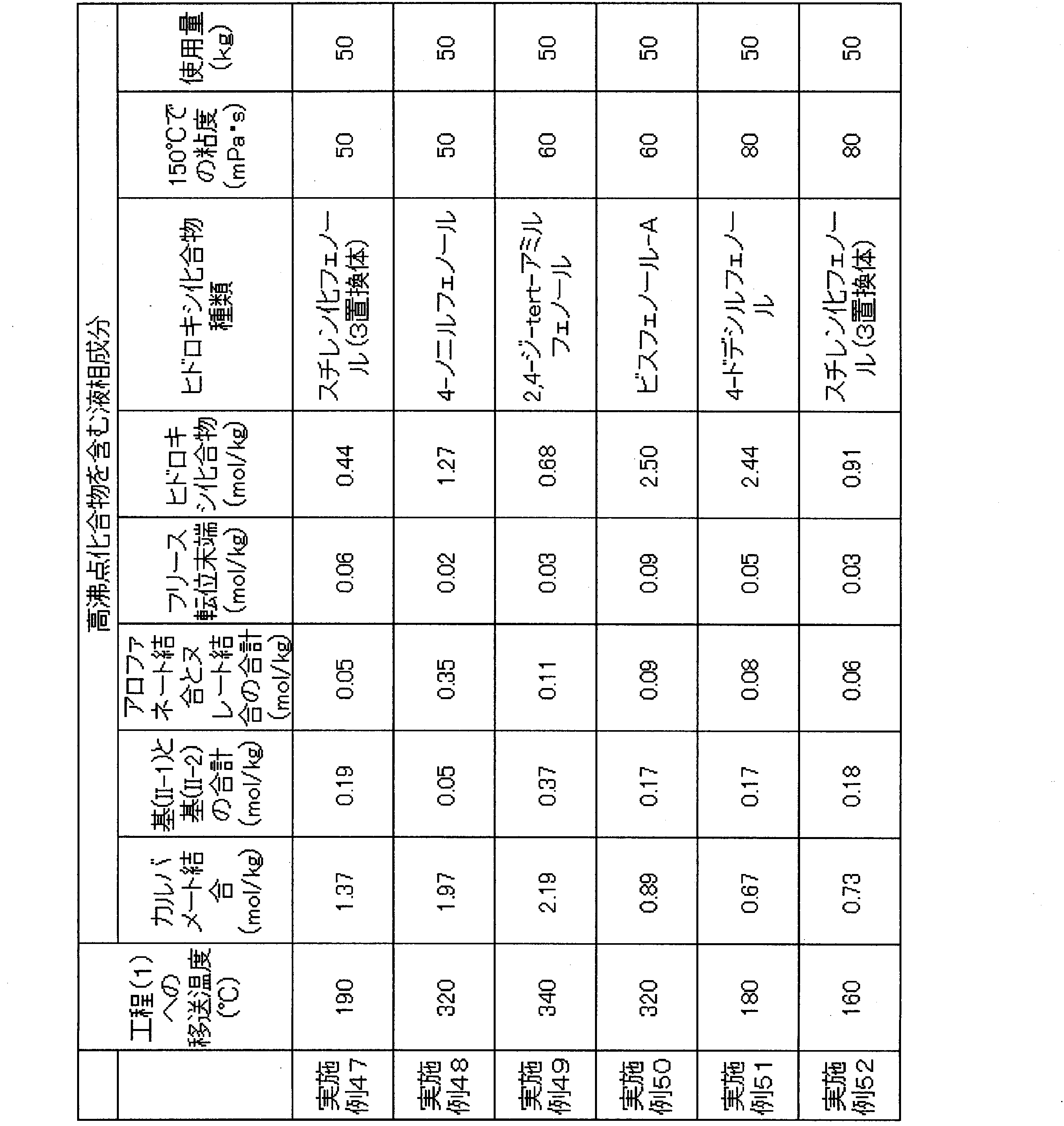


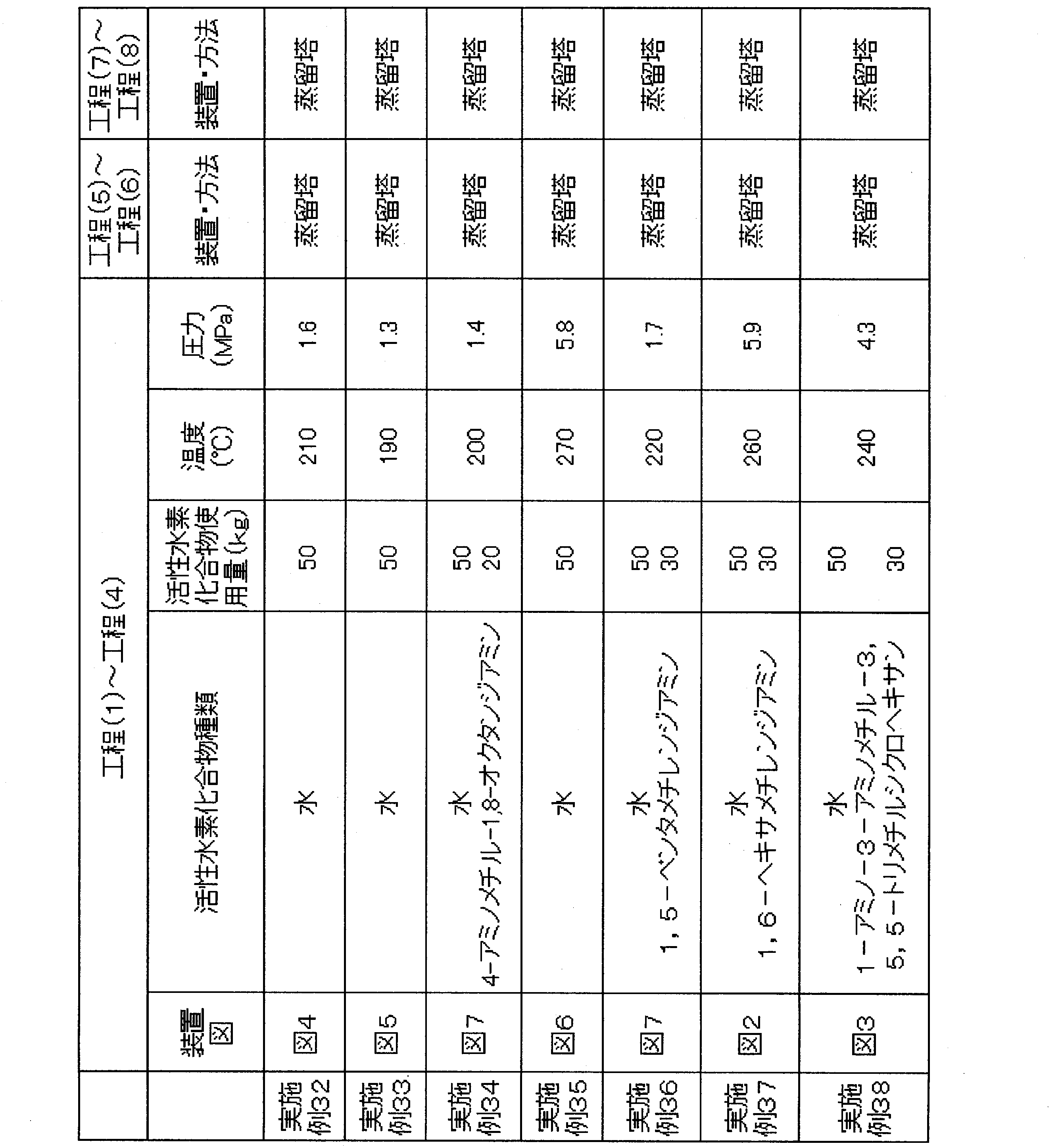
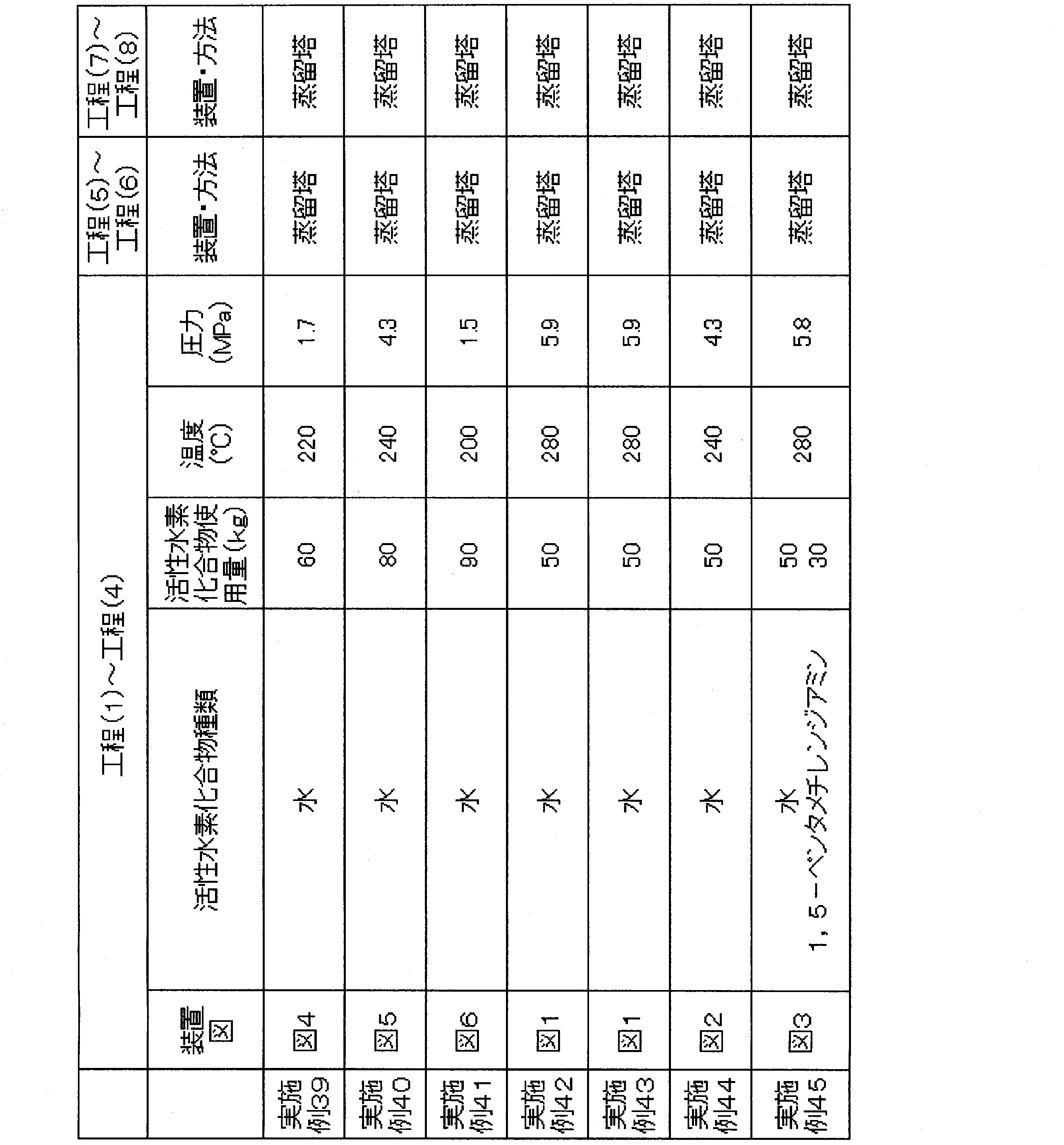

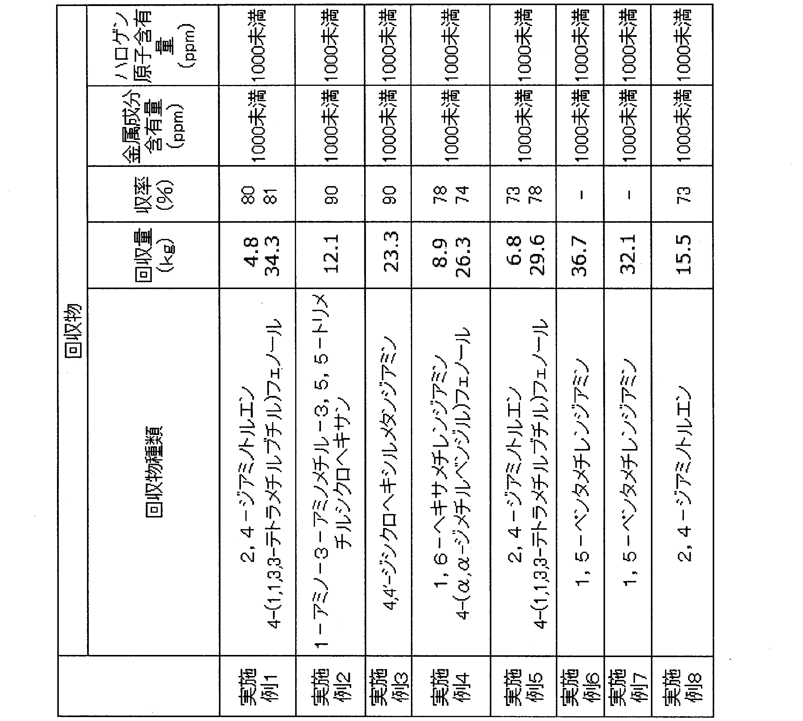
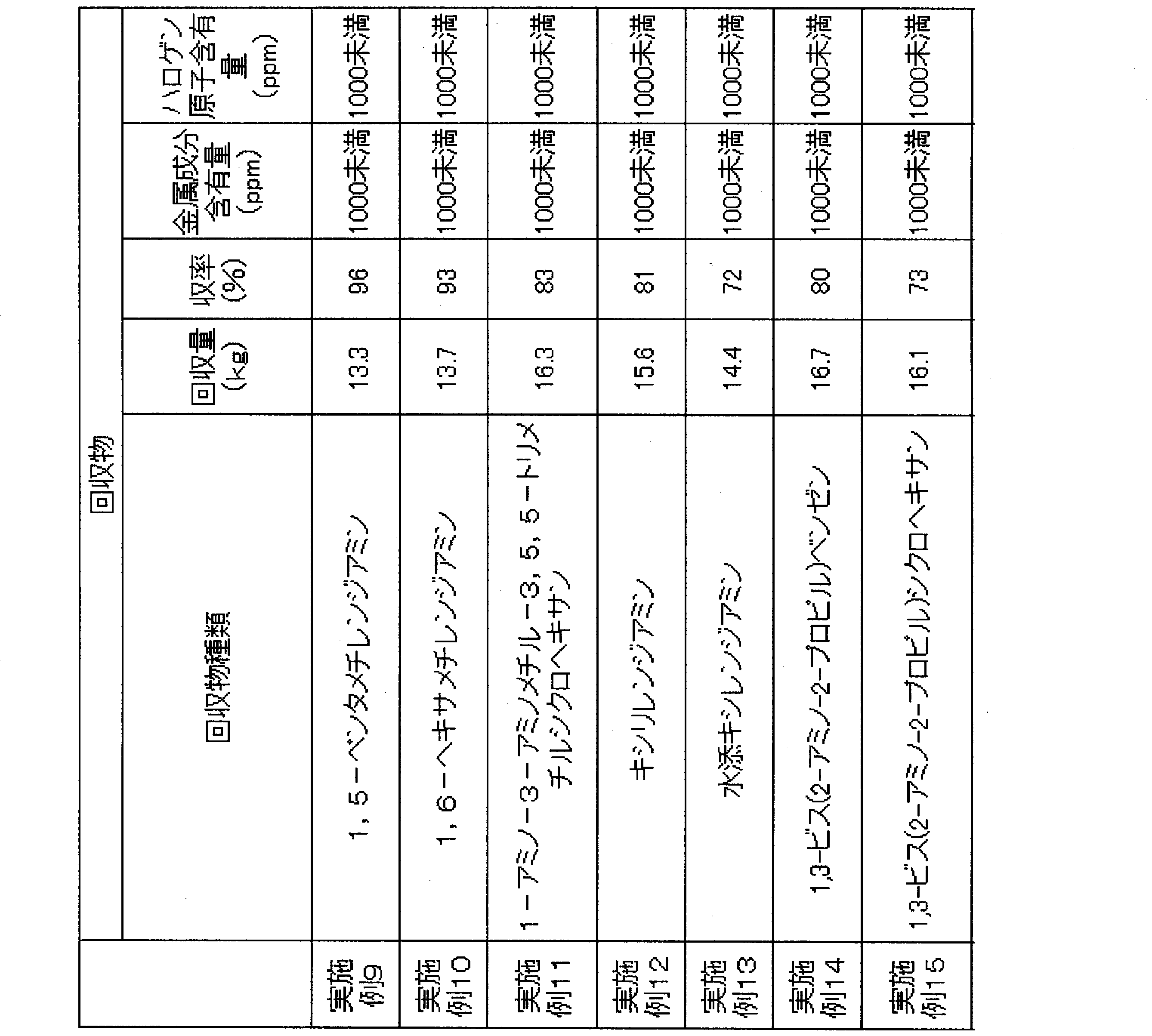
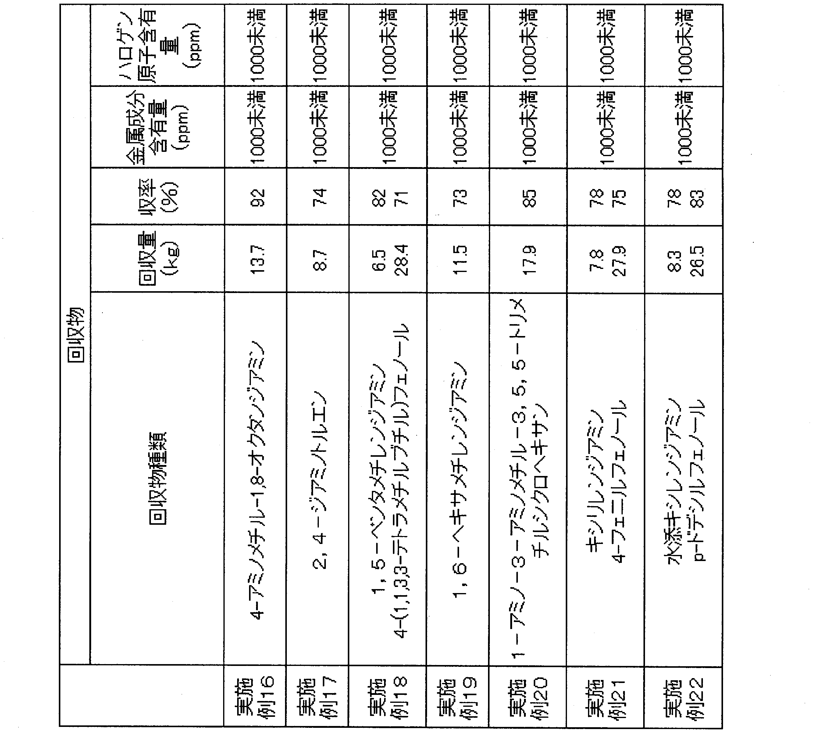
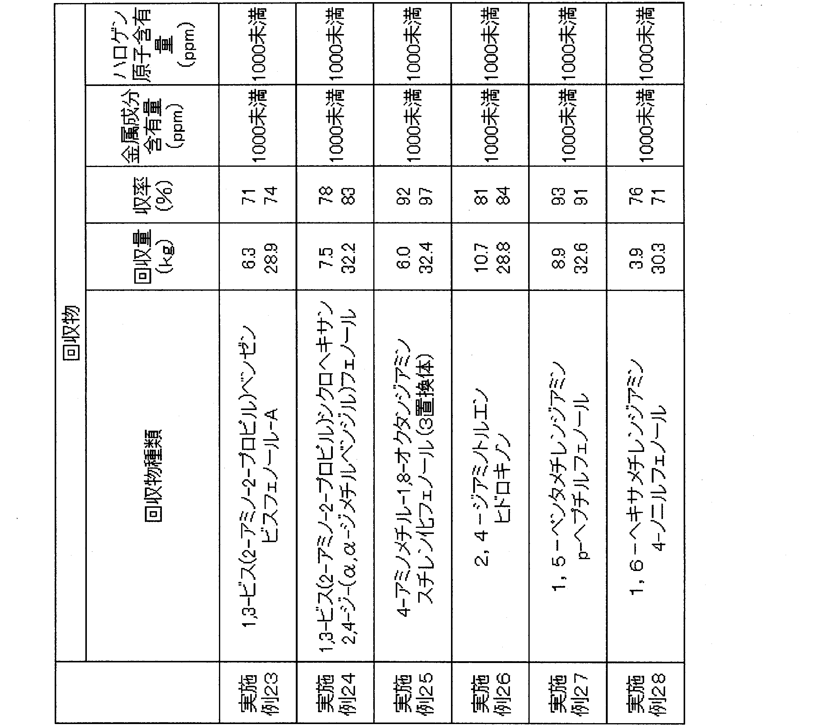


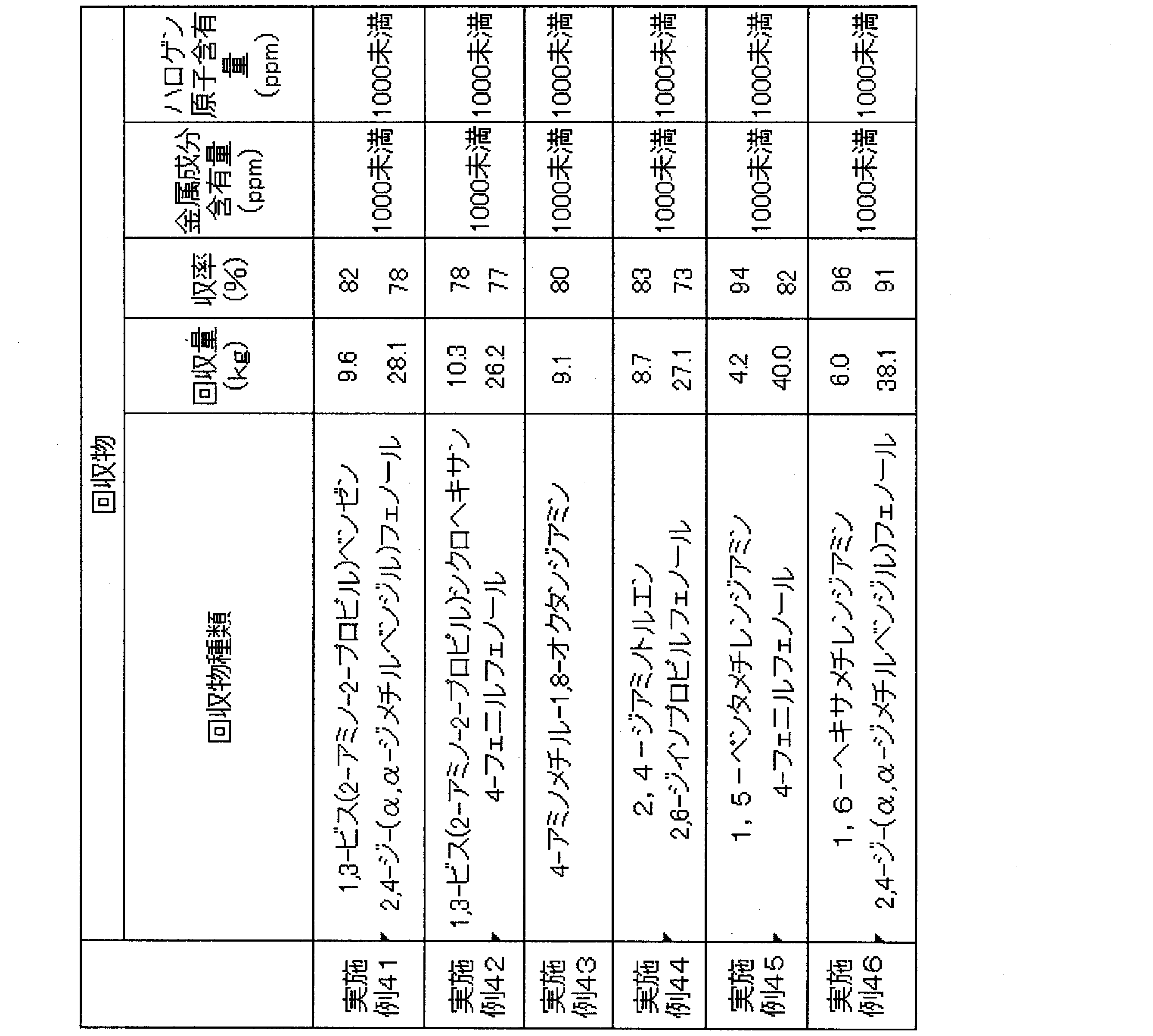
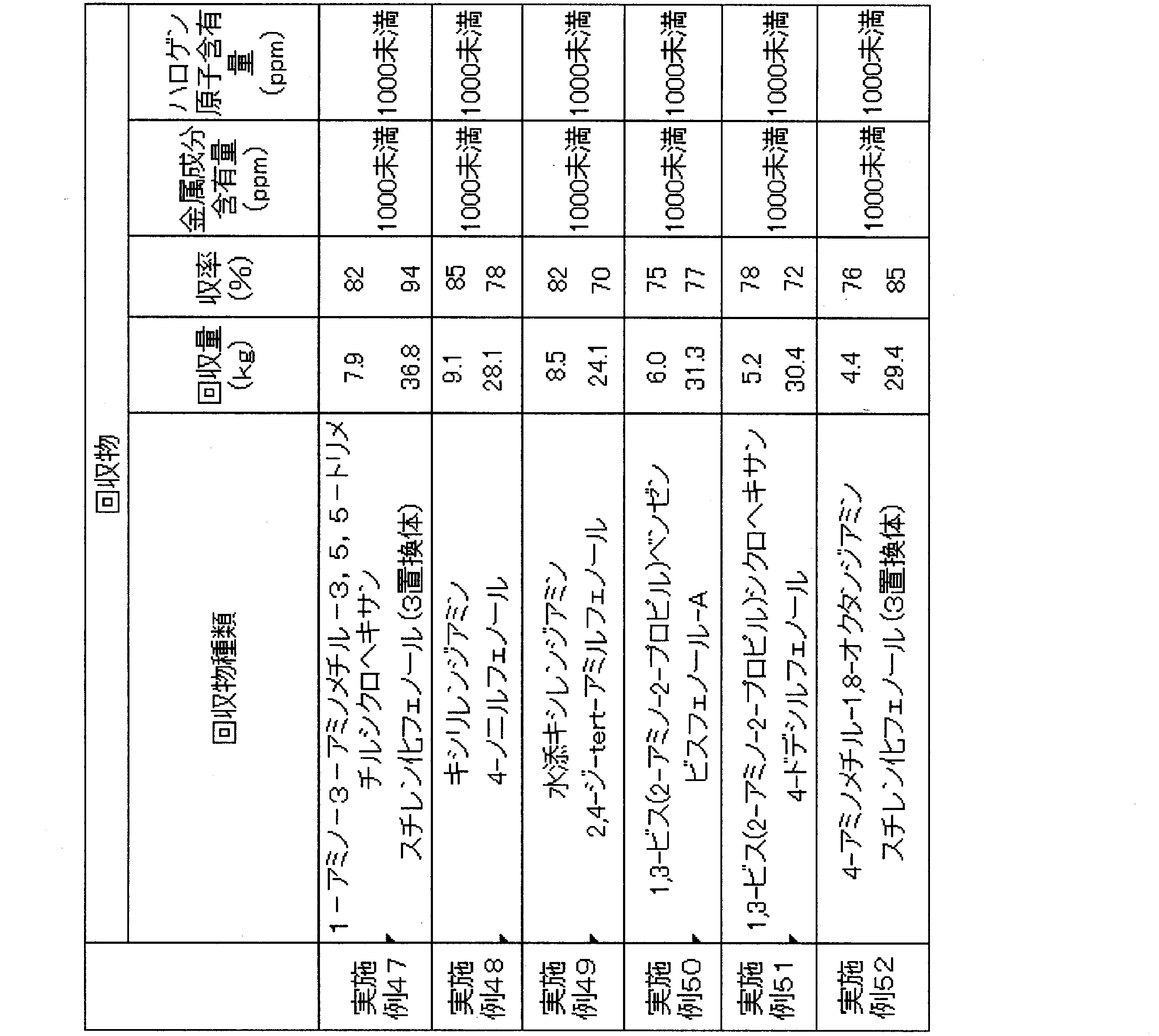
凝縮器B102を冷却せず、実施例1の工程(1-2)に相当する工程をおこなわなかった以外は実施例1と同様の方法をおこない、粗2,4-トルエンジアミンを回収した。その収率は38%であった。また、粗4-(1,1,3,3-テトラメチルブチル)フェノールを回収した。その収率は43%であった。 Comparative Example 1
A crude 2,4-toluenediamine was recovered by the same method as in Example 1 except that the condenser B 102 was not cooled and the step corresponding to the step (1-2) in Example 1 was not performed. The yield was 38%. In addition, crude 4- (1,1,3,3-tetramethylbutyl) phenol was recovered. The yield was 43%.
凝縮器B203を冷却せず、実施例2の工程(2-2)に相当する工程をおこなわなかった以外は実施例2と同様の方法をおこない、粗1-アミノ-3-アミノメチル-3,5,5-トリメチルシクロヘキサンを回収した。その収率は41%であった。 Comparative Example 2
The same method as in Example 2 was carried out except that the condenser B203 was not cooled and the step corresponding to the step (2-2) in Example 2 was not carried out, and crude 1-amino-3-aminomethyl-3, The 5,5-trimethylcyclohexane was recovered. The yield was 41%.
凝縮器303を冷却せず、実施例3の工程(3-2)に相当する工程をおこなわなかった以外は実施例3と同様の方法をおこない、粗4,4’-ジシクロヘキシルメタンジアミンを回収した。その収率は42%であった。 Comparative Example 3
A crude 4,4′-dicyclohexylmethanediamine was recovered by the same method as in Example 3 except that the condenser 303 was not cooled and the step corresponding to the step (3-2) in Example 3 was not performed. . The yield was 42%.
凝縮器405を冷却せず、実施例4の工程(4-2)に相当する工程をおこなわなかった以外は実施例4と同様の方法をおこない、粗1,6-ヘキサメチレンジアミンを回収した。その収率は37%であった。また、粗4-(α,α-ジメチルベンジル)フェノールを回収した。その収率は46%であった。 Comparative Example 4
The
凝縮器506を冷却せず、実施例5の工程(5-2)に相当する工程をおこなわなかった以外は実施例5と同様の方法をおこない、粗2,4-トルエンジアミンを回収した。その収率は48%であった。また、粗4-(1,1,3,3-テトラメチルブチル)フェノールを回収した。その収率は35%であった。 Comparative Example 5
A crude 2,4-toluenediamine was recovered by the same method as in Example 5 except that the condenser 506 was not cooled and the step corresponding to the step (5-2) of Example 5 was not performed. The yield was 48%. In addition, crude 4- (1,1,3,3-tetramethylbutyl) phenol was recovered. The yield was 35%.
凝縮器604を冷却せず、実施例6の工程(6-2)に相当する工程をおこなわなかった以外は実施例6と同様の方法をおこない、粗1,5-ペンタメチレンジアミンを回収した。その収率は32%であった。 Comparative Example 6
A
工程(7-1)において1,5-ペンタメチレンジアミンを添加しなかった以外は実施例7と同様の方法をおこない、粗1,5-ペンタメチレンジアミンを回収した。その収率は22%であった。 Comparative Example 7
A
B101、B301、A501、A701、C101:攪拌槽(耐圧反応器)
B201、B302:反応槽
B102、B203、B303、B405、B506、B604、B704、A103、A114、A115、A203、A302、A402、A405、A408、A603:凝縮器
B103、B205、B305、B406、B507、B605、A204、A205、A303、A304、A502、A604、A605、A702、C103:貯槽
B104、B204、B304、B403、B404、B503、B504、B606、C104、C203、C204、C303、C304:保圧弁
B202:ポンプ
B401、B501、C201、C301:押出機
B402、B502、C202、C302:ベント口
B505、C305:受器
B601、B701、C401:加熱蒸発面
B602、B702、A301、C402:薄膜蒸発機
B603、B703、C403:回収部
A101、A201:連続多段蒸留塔
A601:多段蒸留塔
A102、A401:熱分解装置
A111、A112、A113、A202、A403、A406、A409、A602:リボイラー
A109、A404、A407:分離塔
A110:精製塔 B1, B2, B3, B4, B5, B20, B22, B22, B24, B25, B26, B26, B31, B32, B32, B34, B35, B36, B41, B42, B43, B44, B50, B40 B51, B52, B53, B54, B55, B60, B62, B62, B64, B64, B70, B71, B72, A1, A3, A4, A5, A6, A7, A8, A9, A18, A19, A19, A19, A19 A20, A21, A22, A23, A24, A32, A40, A41, A42, A43, A44, A45, A46, A47, A48, A49, A50, A51, A61, A62, A63, A64, A65, A70, A70, A71, C1, C4, C5, C20, C21, C22, C30, C31, C32, C40, C41, C 2: Line B101, B301, A501, A701, C101: stirred tank (pressure-resistant reactor)
B201, B302: reaction tank B102, B203, B405, B506, B604, B704, A103, A114, A115, A203, A302, A402, A405, A408, A603: condenser B103, B205, B305, B406, B507, B507, B 605, A 204, A 205, A 303, A 304, A 502, A 604, A 605, A 702, C 103: Reservoir B 104, B 204, B 304, B 403, B 404, B 504, B 504, B 606, C 104, C 203, C 204, C 303, C 304: Holding valve B 202 : Pumps B401, B501, C201, C301: Extruders B402, B502, C202, C302: Vent ports B505, C305: Receivers B601, B701, C401: Heating evaporation surface B602, 702, A301, C402: thin film evaporators B603, B703, C403: recovery sections A101, A201: continuous multistage distillation columns A601: multistage distillation columns A102, A401: thermal decomposition units A111, A112, A113, A202, A202, A403, A406, A409 , A602: reboiler A109, A404, A407: separation tower A110: purification tower
Claims (24)
- 下記一般式(I)で表される化合物の製造方法で副生する液相成分から、下記一般式(III)で表される化合物を回収する方法であって、下記工程(1)~工程(4)を含む回収方法。
工程(1):前記液相成分と少なくとも1種の活性水素含有化合物とを反応器内で反応させる工程。
工程(2):前記反応器の気相成分を冷却することにより得られた凝縮液を前記反応器内へ戻す工程。
工程(3):前記工程(2)において、凝縮されなかった気相成分を前記反応器以外へ排出する工程。
工程(4):前記反応器内の液相成分として、前記一般式(III)で表される化合物を含有する反応液を前記反応器外に排出する工程。


Step (1): a step of reacting the liquid phase component and at least one active hydrogen-containing compound in a reactor.
Step (2): returning the condensate obtained by cooling the gas phase components of the reactor into the reactor.
Step (3): A step of discharging the gas phase component not condensed in the step (2) to other than the reactor.
Step (4): discharging the reaction liquid containing the compound represented by the general formula (III) as a liquid phase component in the reactor to the outside of the reactor.
- 前記活性水素含有化合物が、水、尿素、アルコール、芳香族ヒドロキシ化合物および有機第1アミンからなる群から選ばれることを特徴とする、請求項1に記載の回収方法。 The method according to claim 1, wherein the active hydrogen-containing compound is selected from the group consisting of water, urea, an alcohol, an aromatic hydroxy compound and an organic primary amine.
- 下記一般式(I)で表される化合物の製造方法で副生する液相成分から、下記一般式(III)で表される化合物を回収する方法であって、下記工程(A)、工程(B)及び工程(4)を含む回収方法。
工程(A):前記液相成分と水と前記一般式(III)で表される化合物とを混合する工程。
工程(B):前記液相成分と水とを反応器内で反応させる工程。
工程(4):前記反応器内の液相成分として、前記一般式(III)で表される化合物を含有する反応液を前記反応器外に排出する工程。


Step (A): a step of mixing the liquid phase component, water, and the compound represented by the general formula (III).
Step (B): a step of reacting the liquid phase component with water in a reactor.
Step (4): discharging the reaction liquid containing the compound represented by the general formula (III) as a liquid phase component in the reactor to the outside of the reactor.
- 前記一般式(I)で表される化合物の製造方法が、炭酸誘導体とヒドロキシ化合物と前記式(III)で表される化合物から製造する方法である、請求項1~3のいずれか一項に記載の回収方法。 The method according to any one of claims 1 to 3, wherein the method for producing the compound represented by the general formula (I) is a method for producing from a compound represented by a carbonic acid derivative and a hydroxy compound and the formula (III). Recovery method described.
- 前記一般式(I)で表される化合物の製造方法で副生する液相成分が、炭酸誘導体とヒドロキシ化合物と式(III)で表される化合物から製造される、カルバメート含有液を、熱分解反応装置に供給して、前記カルバメートと熱分解反応に付し、生成する前記一般式(I)で表される化合物を含む気相成分を回収する際に熱分解反応装置から抜き出される液相成分である、請求項1~4のいずれか一項に記載の回収方法。 Thermal decomposition of a carbamate-containing liquid, wherein a liquid phase component by-produced by the method for producing a compound represented by the general formula (I) is produced from a carbonic acid derivative, a hydroxy compound and a compound represented by the formula (III) A liquid phase which is supplied to a reactor, subjected to a thermal decomposition reaction with the carbamate, and recovered from the thermal decomposition reactor when recovering a gas phase component containing the compound represented by the general formula (I) to be produced The recovery method according to any one of claims 1 to 4, which is a component.
- 前記熱分解反応装置が、管型反応器と、前記液相成分と前記一般式(I)で表される化合物を含む気相成分を分離する分離槽からなり、前記管型反応器における単位浸辺長流量が10kg/時・m以上1000kg/時・m以下である、請求項5に記載の回収方法。 The thermal decomposition reactor comprises a tubular reactor, and a separation vessel for separating the liquid phase component and the gas phase component containing the compound represented by the general formula (I), and the unit immersion in the tubular reactor The collection method according to claim 5, wherein the side length flow rate is 10 kg / hour · m or more and 1000 kg / hour · m or less.
- 前記液相成分と前記式(I)で表される化合物を含む気相成分を分離する分離槽における気相成分の線速度が10m/秒以下である、請求項5または6に記載の回収方法。 The recovery method according to claim 5 or 6, wherein the linear velocity of the gas phase component in the separation tank separating the liquid phase component and the gas phase component containing the compound represented by the formula (I) is 10 m / s or less. .
- 前記熱分解反応装置から抜き出される液相成分を150℃以上350℃以下に保持した状態で工程1)がおこなわれる反応器に供給する、請求項5~7のいずれか一項に記載の回収方法。 The recovery according to any one of claims 5 to 7, wherein the liquid phase component withdrawn from the thermal decomposition reactor is supplied to a reactor in which step 1) is carried out while maintaining at 150 ° C to 350 ° C. Method.
- 前記液相成分が、ヒドロキシ化合物を含有することを特徴とする、請求項1~8のいずれか一項に記載の回収方法。 The recovery method according to any one of claims 1 to 8, wherein the liquid phase component contains a hydroxy compound.
- 前記液相成分が、下記式(II-1)で表される基及び下記式(II-2)で表される基のうち少なくともいずれか1種類の基を有する化合物を含む、請求項1~8のいずれか一項に記載の回収方法。
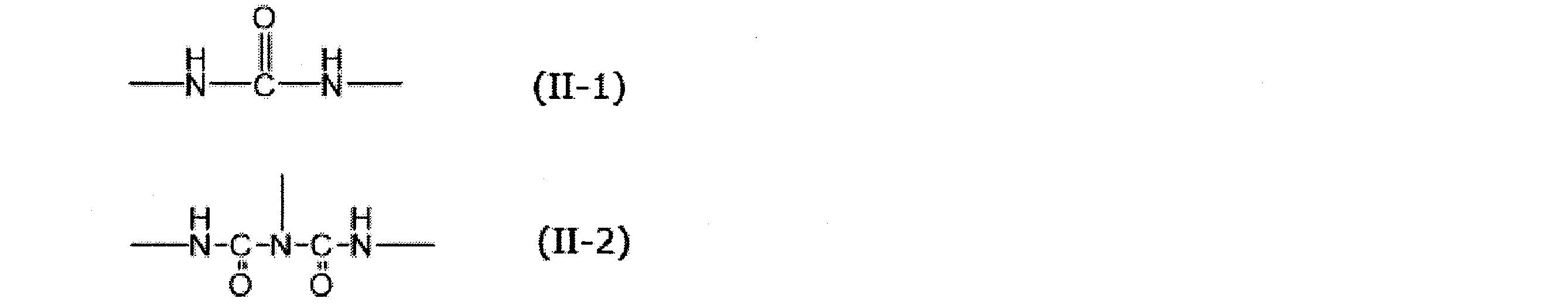
- 前記高沸点化合物を含む液相成分が、ヒドロキシ化合物を、前記液相成分の総質量に対して、20質量%~70質量%含有する、請求項10に記載の回収方法。 The recovery method according to claim 10, wherein the liquid phase component containing the high-boiling point compound contains a hydroxy compound in an amount of 20% by mass to 70% by mass with respect to the total mass of the liquid phase component.
- 前記液相成分の粘度が150℃において100mPa・s以下である、請求項1~11のいずれか一項に記載の回収方法。 The recovery method according to any one of claims 1 to 11, wherein the viscosity of the liquid phase component is 100 mPa · s or less at 150 属 C.
- 前記反応器が、槽型反応器、押出機及び薄膜蒸発機からなる群から選ばれる少なくとも1つの反応器である、請求項1~12のいずれか一項に記載の回収方法。 The recovery method according to any one of claims 1 to 12, wherein the reactor is at least one reactor selected from the group consisting of a tank reactor, an extruder and a thin film evaporator.
- 前記活性水素含有化合物の少なくとも1種が、水であり、工程(3)で排出する気相成分が、二酸化炭素を含む、請求項1、2及び4~12のいずれか一項に記載の回収方法。 The recovery according to any one of claims 1, 2 and 4 to 12, wherein at least one of the active hydrogen-containing compounds is water, and the gas phase component discharged in step (3) comprises carbon dioxide. Method.
- 前記活性水素含有化合物の少なくとも2種が、水及び芳香族ヒドロキシ化合物である、請求項1、2及び4~12のいずれか一項に記載の回収方法。 The recovery method according to any one of claims 1, 2 and 4 to 12, wherein at least two of the active hydrogen-containing compounds are water and an aromatic hydroxy compound.
- 前記活性水素含有化合物の少なくとも2種が、尿素及び芳香族ヒドロキシ化合物であり、工程(3)で排出する気相成分が、二酸化炭素及びアンモニアを含むことを特徴とする、請求項1、2及び4~12のいずれか一項に記載の回収方法。 4. The method according to claim 1, wherein at least two of the active hydrogen-containing compounds are urea and an aromatic hydroxy compound, and the gas phase component discharged in step (3) comprises carbon dioxide and ammonia. The recovery method according to any one of 4 to 12.
- 前記工程(2)の凝縮液が水である、請求項14または15のいずれか一項に記載の回収方法。 The recovery method according to any one of claims 14 or 15, wherein the condensate in step (2) is water.
- 前記活性水素含有化合物として、前記式(III)で表される化合物がさらに用いられる、請求項15~17のいずれか一項に記載の回収方法。 The recovery method according to any one of claims 15 to 17, wherein the compound represented by the formula (III) is further used as the active hydrogen-containing compound.
- 下記工程(5)及び工程(6)をさらに含む、請求項1~18に記載の回収方法。
工程(5):前記工程(4)で得た反応液から前記一般式(III)で表される化合物を分離する工程。
工程(6):前記一般式(III)で表される化合物を精製する工程。 The recovery method according to any one of claims 1 to 18, further comprising the following step (5) and step (6).
Step (5): a step of separating the compound represented by the general formula (III) from the reaction solution obtained in the step (4).
Step (6): a step of purifying the compound represented by the general formula (III). - 前記工程(6)において、前記一般式(III)で表される化合物の総質量に対する金属成分の含有量が1000質量ppm以下およびハロゲン原子の含有量が1000質量ppm以下となるように前記一般式式(III)で表される化合物を蒸留回収することを特徴とする、請求項19に記載の回収方法。 In the step (6), the content of the metal component relative to the total mass of the compound represented by the general formula (III) is 1000 mass ppm or less and the content of the halogen atom is 1000 mass ppm or less The method according to claim 19, wherein the compound represented by the formula (III) is recovered by distillation.
- 前記工程(6)で回収された式(III)で表される化合物を、式(I)で表される化合物の製造工程にリサイクルすることを特徴とする、請求項19または20に記載の回収方法。 The compound according to claim 19 or 20, wherein the compound represented by the formula (III) recovered in the step (6) is recycled to the production process of the compound represented by the formula (I). Method.
- 前記液相成分が、式(IV)で表される基を有する化合物を含有し、
前記工程(5)において、前記工程(4)で得た反応液から、前記式(III)で表される化合物と共に、下記式(V)で表される化合物を分離し、
さらに、前記工程(6)の後に、下記工程(7)を含む、請求項19~21のいずれか一項に記載の回収方法。
工程(7):式(V)で表される化合物を精製する工程
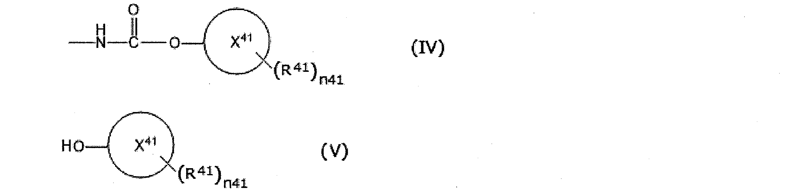
In the step (5), a compound represented by the following formula (V) is separated from the reaction solution obtained in the step (4) together with the compound represented by the formula (III):
The recovery method according to any one of claims 19 to 21, further comprising the following step (7) after the step (6).
Step (7): Step of purifying a compound represented by Formula (V)
- 前記工程(7)において、前記一般式(V)で表される化合物の総質量に対する金属成分の含有量が1000質量ppm以下およびハロゲン原子の含有量が1000質量ppm以下となるように前記一般式(V)で表される化合物を蒸留回収する、請求項22記載の回収方法。 In the step (7), the content of the metal component relative to the total mass of the compound represented by the general formula (V) is 1000 mass ppm or less and the content of the halogen atom is 1000 mass ppm or less The method according to claim 22, wherein the compound represented by (V) is recovered by distillation.
- 前記工程(7)で回収された前記一般式(V)で表される化合物を、前記一般式(I)で表される化合物の製造工程にリサイクルする、請求項22または23に記載の回収方法。 The method according to claim 22 or 23, wherein the compound represented by the general formula (V) recovered in the step (7) is recycled to the production process of the compound represented by the general formula (I) .
Priority Applications (7)
| Application Number | Priority Date | Filing Date | Title |
|---|---|---|---|
| BR112020012743-4A BR112020012743B1 (en) | 2017-12-27 | 2018-12-27 | COMPOUND COLLECTION METHOD |
| EP18896283.1A EP3733644B1 (en) | 2017-12-27 | 2018-12-27 | Organic amine collection method |
| US16/954,318 US11578030B2 (en) | 2017-12-27 | 2018-12-27 | Organic amine collection method |
| EP21169951.7A EP3872062B1 (en) | 2017-12-27 | 2018-12-27 | Organic amine collection method |
| CN201880064796.3A CN111183131B (en) | 2017-12-27 | 2018-12-27 | Method for recovering organic amine |
| JP2019562151A JP6937847B2 (en) | 2017-12-27 | 2018-12-27 | How to recover organic amines |
| US18/091,697 US20230139979A1 (en) | 2017-12-27 | 2022-12-30 | Organic amine collection method |
Applications Claiming Priority (4)
| Application Number | Priority Date | Filing Date | Title |
|---|---|---|---|
| JP2017-252607 | 2017-12-27 | ||
| JP2017252607 | 2017-12-27 | ||
| JP2018014143 | 2018-01-30 | ||
| JP2018-014143 | 2018-01-30 |
Related Child Applications (2)
| Application Number | Title | Priority Date | Filing Date |
|---|---|---|---|
| US16/954,318 A-371-Of-International US11578030B2 (en) | 2017-12-27 | 2018-12-27 | Organic amine collection method |
| US18/091,697 Division US20230139979A1 (en) | 2017-12-27 | 2022-12-30 | Organic amine collection method |
Publications (1)
| Publication Number | Publication Date |
|---|---|
| WO2019131855A1 true WO2019131855A1 (en) | 2019-07-04 |
Family
ID=67063867
Family Applications (1)
| Application Number | Title | Priority Date | Filing Date |
|---|---|---|---|
| PCT/JP2018/048087 WO2019131855A1 (en) | 2017-12-27 | 2018-12-27 | Organic amine collection method |
Country Status (7)
| Country | Link |
|---|---|
| US (2) | US11578030B2 (en) |
| EP (2) | EP3733644B1 (en) |
| JP (2) | JP6937847B2 (en) |
| CN (1) | CN111183131B (en) |
| BR (1) | BR112020012743B1 (en) |
| TW (1) | TW201930259A (en) |
| WO (1) | WO2019131855A1 (en) |
Cited By (1)
| Publication number | Priority date | Publication date | Assignee | Title |
|---|---|---|---|---|
| WO2023080257A1 (en) * | 2021-11-08 | 2023-05-11 | 旭化成株式会社 | Method for producing isocyanate compounds, method for producing carbamate compounds, method for recovering amine compounds, and isocyanate composition |
Citations (14)
| Publication number | Priority date | Publication date | Assignee | Title |
|---|---|---|---|---|
| JPS5240678B2 (en) | 1973-11-14 | 1977-10-13 | ||
| JPS5848538B2 (en) | 1978-03-31 | 1983-10-28 | 三井東圧化学株式会社 | Amine recovery method |
| JP2002173471A (en) | 2000-12-07 | 2002-06-21 | Kobe Steel Ltd | Method for splitting and collecting isocyanate-based to- be-split compound |
| JP2002518369A (en) | 1998-06-18 | 2002-06-25 | ビーエーエスエフ アクチェンゲゼルシャフト | Post-treatment of distillation residue generated in the synthesis of tolylene diisocyanate |
| WO2007036479A1 (en) | 2005-09-29 | 2007-04-05 | Basf Se | Method for purifying residues containing isocyanates |
| WO2009127591A2 (en) | 2008-04-14 | 2009-10-22 | Basf Se | Method for treating residues from the production of isocyanates |
| WO2009130842A1 (en) | 2008-04-26 | 2009-10-29 | 日本ポリウレタン工業株式会社 | Method for breaking down urea compounds |
| WO2009139062A1 (en) * | 2008-05-15 | 2009-11-19 | 旭化成ケミカルズ株式会社 | Process for producing isocyanate |
| WO2011078000A1 (en) * | 2009-12-24 | 2011-06-30 | 三井化学株式会社 | Method for treatment of isocyanate residue, and method for treatment of carbonate |
| WO2014069605A1 (en) | 2012-11-01 | 2014-05-08 | 旭化成ケミカルズ株式会社 | Polyisocyanate composition and isocyanate polymer composition |
| JP5563886B2 (en) | 2010-05-11 | 2014-07-30 | 三井化学株式会社 | Treatment method of isocyanate residue |
| JP5563816B2 (en) | 2009-12-24 | 2014-07-30 | 三井化学株式会社 | Treatment method of isocyanate residue |
| WO2014157636A1 (en) * | 2013-03-29 | 2014-10-02 | 旭化成ケミカルズ株式会社 | Method for producing isocyanate |
| JP2018014143A (en) | 2017-10-26 | 2018-01-25 | 株式会社ナビタイムジャパン | Information processing system, information processing apparatus, information processing method, and information processing program |
Family Cites Families (14)
| Publication number | Priority date | Publication date | Assignee | Title |
|---|---|---|---|---|
| GB795639A (en) * | 1955-09-09 | 1958-05-28 | Bayer Ag | A process for recovering amines from the residues in the production of aromatic isocyanates |
| US3499035A (en) | 1967-10-02 | 1970-03-03 | Olin Mathieson | Toluene diamine recovery process |
| JPS588380B2 (en) | 1974-05-09 | 1983-02-15 | 武田薬品工業株式会社 | Manufacturing method of organic amines |
| US4137266A (en) * | 1976-09-27 | 1979-01-30 | Olin Corporation | Process for toluene diamine recovery |
| DE2703313A1 (en) * | 1977-01-27 | 1978-08-03 | Bayer Ag | PROCESS FOR THE PRODUCTION OF ORGANIC POLYAMINES |
| JPS58201751A (en) * | 1982-05-17 | 1983-11-24 | Mitsui Toatsu Chem Inc | Recovery of amine |
| US4654443A (en) * | 1985-03-11 | 1987-03-31 | The Dow Chemical Company | Hydrolysis of isocyanate distillation bottoms |
| US5902459A (en) | 1996-06-10 | 1999-05-11 | Basf Corporation | Recovery of products from toluenediisocyanate residues |
| EP0976719B1 (en) | 1997-02-05 | 2005-01-05 | Kabushiki Kaisha Kobe Seiko Sho | Apparatus and method for decomposing and recovering isocyanate compound |
| JP4356907B2 (en) | 1997-02-05 | 2009-11-04 | 三井化学ポリウレタン株式会社 | Decomposition and recovery method of isocyanate-based decomposition target compound and its decomposition and recovery equipment |
| WO2000068180A1 (en) | 1999-05-05 | 2000-11-16 | The Dow Chemical Company | A process for recovering toluene diamine from toluene diisocyanate distillation residues |
| KR100578607B1 (en) | 2003-06-09 | 2006-05-10 | 한화석유화학 주식회사 | Method for Recovering Toluene Diamine from High Boiling Tar Residue Discharged from Toluene Diisocyanate Preparation Process |
| CN102633651B (en) * | 2011-01-27 | 2013-10-02 | 沧州丰源环保科技有限公司 | Toluene diamine recovery from tar waste residues discharged during toluene diisocyanate synthesis |
| JP5744619B2 (en) | 2011-05-18 | 2015-07-08 | 三井化学株式会社 | Process for producing tolylene diisocyanate |
-
2018
- 2018-12-27 EP EP18896283.1A patent/EP3733644B1/en active Active
- 2018-12-27 CN CN201880064796.3A patent/CN111183131B/en active Active
- 2018-12-27 BR BR112020012743-4A patent/BR112020012743B1/en active IP Right Grant
- 2018-12-27 US US16/954,318 patent/US11578030B2/en active Active
- 2018-12-27 WO PCT/JP2018/048087 patent/WO2019131855A1/en unknown
- 2018-12-27 TW TW107147439A patent/TW201930259A/en unknown
- 2018-12-27 JP JP2019562151A patent/JP6937847B2/en active Active
- 2018-12-27 EP EP21169951.7A patent/EP3872062B1/en active Active
-
2021
- 2021-08-30 JP JP2021140497A patent/JP7214806B2/en active Active
-
2022
- 2022-12-30 US US18/091,697 patent/US20230139979A1/en active Pending
Patent Citations (14)
| Publication number | Priority date | Publication date | Assignee | Title |
|---|---|---|---|---|
| JPS5240678B2 (en) | 1973-11-14 | 1977-10-13 | ||
| JPS5848538B2 (en) | 1978-03-31 | 1983-10-28 | 三井東圧化学株式会社 | Amine recovery method |
| JP2002518369A (en) | 1998-06-18 | 2002-06-25 | ビーエーエスエフ アクチェンゲゼルシャフト | Post-treatment of distillation residue generated in the synthesis of tolylene diisocyanate |
| JP2002173471A (en) | 2000-12-07 | 2002-06-21 | Kobe Steel Ltd | Method for splitting and collecting isocyanate-based to- be-split compound |
| WO2007036479A1 (en) | 2005-09-29 | 2007-04-05 | Basf Se | Method for purifying residues containing isocyanates |
| WO2009127591A2 (en) | 2008-04-14 | 2009-10-22 | Basf Se | Method for treating residues from the production of isocyanates |
| WO2009130842A1 (en) | 2008-04-26 | 2009-10-29 | 日本ポリウレタン工業株式会社 | Method for breaking down urea compounds |
| WO2009139062A1 (en) * | 2008-05-15 | 2009-11-19 | 旭化成ケミカルズ株式会社 | Process for producing isocyanate |
| WO2011078000A1 (en) * | 2009-12-24 | 2011-06-30 | 三井化学株式会社 | Method for treatment of isocyanate residue, and method for treatment of carbonate |
| JP5563816B2 (en) | 2009-12-24 | 2014-07-30 | 三井化学株式会社 | Treatment method of isocyanate residue |
| JP5563886B2 (en) | 2010-05-11 | 2014-07-30 | 三井化学株式会社 | Treatment method of isocyanate residue |
| WO2014069605A1 (en) | 2012-11-01 | 2014-05-08 | 旭化成ケミカルズ株式会社 | Polyisocyanate composition and isocyanate polymer composition |
| WO2014157636A1 (en) * | 2013-03-29 | 2014-10-02 | 旭化成ケミカルズ株式会社 | Method for producing isocyanate |
| JP2018014143A (en) | 2017-10-26 | 2018-01-25 | 株式会社ナビタイムジャパン | Information processing system, information processing apparatus, information processing method, and information processing program |
Non-Patent Citations (1)
| Title |
|---|
| See also references of EP3733644A4 |
Cited By (1)
| Publication number | Priority date | Publication date | Assignee | Title |
|---|---|---|---|---|
| WO2023080257A1 (en) * | 2021-11-08 | 2023-05-11 | 旭化成株式会社 | Method for producing isocyanate compounds, method for producing carbamate compounds, method for recovering amine compounds, and isocyanate composition |
Also Published As
| Publication number | Publication date |
|---|---|
| US20230139979A1 (en) | 2023-05-04 |
| EP3733644A1 (en) | 2020-11-04 |
| EP3872062A1 (en) | 2021-09-01 |
| BR112020012743B1 (en) | 2023-05-09 |
| CN111183131B (en) | 2022-06-28 |
| BR112020012743A2 (en) | 2020-12-01 |
| TW201930259A (en) | 2019-08-01 |
| JP7214806B2 (en) | 2023-01-30 |
| EP3872062B1 (en) | 2022-09-07 |
| EP3733644A4 (en) | 2020-12-30 |
| JPWO2019131855A1 (en) | 2020-06-18 |
| US20210155573A1 (en) | 2021-05-27 |
| CN111183131A (en) | 2020-05-19 |
| JP2021191772A (en) | 2021-12-16 |
| US11578030B2 (en) | 2023-02-14 |
| EP3733644B1 (en) | 2022-09-07 |
| JP6937847B2 (en) | 2021-09-22 |
Similar Documents
| Publication | Publication Date | Title |
|---|---|---|
| JP5449082B2 (en) | Method for producing methylene dianiline and methylene bis (phenyl isocyanate) | |
| JP3290240B2 (en) | Continuous multistage process for producing (cyclic) aliphatic diisocyanates | |
| CN102105439B (en) | The manufacture method of the manufacture method of N-substituted carbamate and the isocyanic ester of this N-substituted carbamate of use | |
| KR101893177B1 (en) | Method for producing isocyanate | |
| US8492580B2 (en) | Process for preparing isocyanates | |
| CN111630027B (en) | Process for preparing isocyanates | |
| US10703713B2 (en) | Process for preparing an isocyanate | |
| US10112892B2 (en) | Process for preparing polyisocyanates | |
| JP7214806B2 (en) | Method for recovering organic amine | |
| CN101263109B (en) | Process for the preparation of isocyanates | |
| KR20180022844A (en) | Methods for providing hydrogen chloride for chemical reactions | |
| EP1902016B1 (en) | Method for concentrating and treating polyisocyanate residues | |
| US20080200721A1 (en) | Mdi Production By Means of Liquid Phase and Gas Phase Phosgenation | |
| WO2023080257A1 (en) | Method for producing isocyanate compounds, method for producing carbamate compounds, method for recovering amine compounds, and isocyanate composition | |
| CN113480452A (en) | Method for producing isocyanates in dialkyl carbonates as solvents | |
| JP2022170318A (en) | Method for producing isocyanate | |
| JP2023092840A (en) | Production method of isocyanate | |
| CN114423735A (en) | Method for producing isocyanates |
Legal Events
| Date | Code | Title | Description |
|---|---|---|---|
| 121 | Ep: the epo has been informed by wipo that ep was designated in this application |
Ref document number: 18896283 Country of ref document: EP Kind code of ref document: A1 |
|
| ENP | Entry into the national phase |
Ref document number: 2019562151 Country of ref document: JP Kind code of ref document: A |
|
| NENP | Non-entry into the national phase |
Ref country code: DE |
|
| ENP | Entry into the national phase |
Ref document number: 2018896283 Country of ref document: EP Effective date: 20200727 |
|
| REG | Reference to national code |
Ref country code: BR Ref legal event code: B01A Ref document number: 112020012743 Country of ref document: BR |
|
| ENP | Entry into the national phase |
Ref document number: 112020012743 Country of ref document: BR Kind code of ref document: A2 Effective date: 20200622 |