WO2019131604A1 - Engine - Google Patents
Engine Download PDFInfo
- Publication number
- WO2019131604A1 WO2019131604A1 PCT/JP2018/047512 JP2018047512W WO2019131604A1 WO 2019131604 A1 WO2019131604 A1 WO 2019131604A1 JP 2018047512 W JP2018047512 W JP 2018047512W WO 2019131604 A1 WO2019131604 A1 WO 2019131604A1
- Authority
- WO
- WIPO (PCT)
- Prior art keywords
- engine
- engine body
- fuel system
- intake passage
- system component
- Prior art date
Links
Images


Classifications
-
- F—MECHANICAL ENGINEERING; LIGHTING; HEATING; WEAPONS; BLASTING
- F02—COMBUSTION ENGINES; HOT-GAS OR COMBUSTION-PRODUCT ENGINE PLANTS
- F02M—SUPPLYING COMBUSTION ENGINES IN GENERAL WITH COMBUSTIBLE MIXTURES OR CONSTITUENTS THEREOF
- F02M35/00—Combustion-air cleaners, air intakes, intake silencers, or induction systems specially adapted for, or arranged on, internal-combustion engines
- F02M35/10—Air intakes; Induction systems
- F02M35/10006—Air intakes; Induction systems characterised by the position of elements of the air intake system in direction of the air intake flow, i.e. between ambient air inlet and supply to the combustion chamber
- F02M35/10078—Connections of intake systems to the engine
-
- B—PERFORMING OPERATIONS; TRANSPORTING
- B60—VEHICLES IN GENERAL
- B60K—ARRANGEMENT OR MOUNTING OF PROPULSION UNITS OR OF TRANSMISSIONS IN VEHICLES; ARRANGEMENT OR MOUNTING OF PLURAL DIVERSE PRIME-MOVERS IN VEHICLES; AUXILIARY DRIVES FOR VEHICLES; INSTRUMENTATION OR DASHBOARDS FOR VEHICLES; ARRANGEMENTS IN CONNECTION WITH COOLING, AIR INTAKE, GAS EXHAUST OR FUEL SUPPLY OF PROPULSION UNITS IN VEHICLES
- B60K15/00—Arrangement in connection with fuel supply of combustion engines or other fuel consuming energy converters, e.g. fuel cells; Mounting or construction of fuel tanks
- B60K15/01—Arrangement of fuel conduits
-
- F—MECHANICAL ENGINEERING; LIGHTING; HEATING; WEAPONS; BLASTING
- F02—COMBUSTION ENGINES; HOT-GAS OR COMBUSTION-PRODUCT ENGINE PLANTS
- F02B—INTERNAL-COMBUSTION PISTON ENGINES; COMBUSTION ENGINES IN GENERAL
- F02B67/00—Engines characterised by the arrangement of auxiliary apparatus not being otherwise provided for, e.g. the apparatus having different functions; Driving auxiliary apparatus from engines, not otherwise provided for
- F02B67/04—Engines characterised by the arrangement of auxiliary apparatus not being otherwise provided for, e.g. the apparatus having different functions; Driving auxiliary apparatus from engines, not otherwise provided for of mechanically-driven auxiliary apparatus
- F02B67/06—Engines characterised by the arrangement of auxiliary apparatus not being otherwise provided for, e.g. the apparatus having different functions; Driving auxiliary apparatus from engines, not otherwise provided for of mechanically-driven auxiliary apparatus driven by means of chains, belts, or like endless members
-
- F—MECHANICAL ENGINEERING; LIGHTING; HEATING; WEAPONS; BLASTING
- F02—COMBUSTION ENGINES; HOT-GAS OR COMBUSTION-PRODUCT ENGINE PLANTS
- F02B—INTERNAL-COMBUSTION PISTON ENGINES; COMBUSTION ENGINES IN GENERAL
- F02B67/00—Engines characterised by the arrangement of auxiliary apparatus not being otherwise provided for, e.g. the apparatus having different functions; Driving auxiliary apparatus from engines, not otherwise provided for
- F02B67/10—Engines characterised by the arrangement of auxiliary apparatus not being otherwise provided for, e.g. the apparatus having different functions; Driving auxiliary apparatus from engines, not otherwise provided for of charging or scavenging apparatus
-
- F—MECHANICAL ENGINEERING; LIGHTING; HEATING; WEAPONS; BLASTING
- F02—COMBUSTION ENGINES; HOT-GAS OR COMBUSTION-PRODUCT ENGINE PLANTS
- F02D—CONTROLLING COMBUSTION ENGINES
- F02D9/00—Controlling engines by throttling air or fuel-and-air induction conduits or exhaust conduits
- F02D9/08—Throttle valves specially adapted therefor; Arrangements of such valves in conduits
-
- F—MECHANICAL ENGINEERING; LIGHTING; HEATING; WEAPONS; BLASTING
- F02—COMBUSTION ENGINES; HOT-GAS OR COMBUSTION-PRODUCT ENGINE PLANTS
- F02F—CYLINDERS, PISTONS OR CASINGS, FOR COMBUSTION ENGINES; ARRANGEMENTS OF SEALINGS IN COMBUSTION ENGINES
- F02F1/00—Cylinders; Cylinder heads
- F02F1/24—Cylinder heads
-
- F—MECHANICAL ENGINEERING; LIGHTING; HEATING; WEAPONS; BLASTING
- F02—COMBUSTION ENGINES; HOT-GAS OR COMBUSTION-PRODUCT ENGINE PLANTS
- F02M—SUPPLYING COMBUSTION ENGINES IN GENERAL WITH COMBUSTIBLE MIXTURES OR CONSTITUENTS THEREOF
- F02M35/00—Combustion-air cleaners, air intakes, intake silencers, or induction systems specially adapted for, or arranged on, internal-combustion engines
- F02M35/10—Air intakes; Induction systems
- F02M35/1015—Air intakes; Induction systems characterised by the engine type
- F02M35/10157—Supercharged engines
-
- F—MECHANICAL ENGINEERING; LIGHTING; HEATING; WEAPONS; BLASTING
- F02—COMBUSTION ENGINES; HOT-GAS OR COMBUSTION-PRODUCT ENGINE PLANTS
- F02M—SUPPLYING COMBUSTION ENGINES IN GENERAL WITH COMBUSTIBLE MIXTURES OR CONSTITUENTS THEREOF
- F02M35/00—Combustion-air cleaners, air intakes, intake silencers, or induction systems specially adapted for, or arranged on, internal-combustion engines
- F02M35/10—Air intakes; Induction systems
- F02M35/10209—Fluid connections to the air intake system; their arrangement of pipes, valves or the like
- F02M35/10216—Fuel injectors; Fuel pipes or rails; Fuel pumps or pressure regulators
-
- F—MECHANICAL ENGINEERING; LIGHTING; HEATING; WEAPONS; BLASTING
- F02—COMBUSTION ENGINES; HOT-GAS OR COMBUSTION-PRODUCT ENGINE PLANTS
- F02M—SUPPLYING COMBUSTION ENGINES IN GENERAL WITH COMBUSTIBLE MIXTURES OR CONSTITUENTS THEREOF
- F02M35/00—Combustion-air cleaners, air intakes, intake silencers, or induction systems specially adapted for, or arranged on, internal-combustion engines
- F02M35/10—Air intakes; Induction systems
- F02M35/10242—Devices or means connected to or integrated into air intakes; Air intakes combined with other engine or vehicle parts
- F02M35/10255—Arrangements of valves; Multi-way valves
-
- F—MECHANICAL ENGINEERING; LIGHTING; HEATING; WEAPONS; BLASTING
- F02—COMBUSTION ENGINES; HOT-GAS OR COMBUSTION-PRODUCT ENGINE PLANTS
- F02M—SUPPLYING COMBUSTION ENGINES IN GENERAL WITH COMBUSTIBLE MIXTURES OR CONSTITUENTS THEREOF
- F02M35/00—Combustion-air cleaners, air intakes, intake silencers, or induction systems specially adapted for, or arranged on, internal-combustion engines
- F02M35/10—Air intakes; Induction systems
- F02M35/104—Intake manifolds
-
- F—MECHANICAL ENGINEERING; LIGHTING; HEATING; WEAPONS; BLASTING
- F02—COMBUSTION ENGINES; HOT-GAS OR COMBUSTION-PRODUCT ENGINE PLANTS
- F02M—SUPPLYING COMBUSTION ENGINES IN GENERAL WITH COMBUSTIBLE MIXTURES OR CONSTITUENTS THEREOF
- F02M35/00—Combustion-air cleaners, air intakes, intake silencers, or induction systems specially adapted for, or arranged on, internal-combustion engines
- F02M35/16—Combustion-air cleaners, air intakes, intake silencers, or induction systems specially adapted for, or arranged on, internal-combustion engines characterised by use in vehicles
-
- F—MECHANICAL ENGINEERING; LIGHTING; HEATING; WEAPONS; BLASTING
- F02—COMBUSTION ENGINES; HOT-GAS OR COMBUSTION-PRODUCT ENGINE PLANTS
- F02M—SUPPLYING COMBUSTION ENGINES IN GENERAL WITH COMBUSTIBLE MIXTURES OR CONSTITUENTS THEREOF
- F02M37/00—Apparatus or systems for feeding liquid fuel from storage containers to carburettors or fuel-injection apparatus; Arrangements for purifying liquid fuel specially adapted for, or arranged on, internal-combustion engines
- F02M37/0011—Constructional details; Manufacturing or assembly of elements of fuel systems; Materials therefor
- F02M37/0017—Constructional details; Manufacturing or assembly of elements of fuel systems; Materials therefor related to fuel pipes or their connections, e.g. joints or sealings
-
- B—PERFORMING OPERATIONS; TRANSPORTING
- B60—VEHICLES IN GENERAL
- B60Y—INDEXING SCHEME RELATING TO ASPECTS CROSS-CUTTING VEHICLE TECHNOLOGY
- B60Y2306/00—Other features of vehicle sub-units
- B60Y2306/01—Reducing damages in case of crash, e.g. by improving battery protection
-
- F—MECHANICAL ENGINEERING; LIGHTING; HEATING; WEAPONS; BLASTING
- F02—COMBUSTION ENGINES; HOT-GAS OR COMBUSTION-PRODUCT ENGINE PLANTS
- F02M—SUPPLYING COMBUSTION ENGINES IN GENERAL WITH COMBUSTIBLE MIXTURES OR CONSTITUENTS THEREOF
- F02M2200/00—Details of fuel-injection apparatus, not otherwise provided for
- F02M2200/18—Fuel-injection apparatus having means for maintaining safety not otherwise provided for
- F02M2200/185—Fuel-injection apparatus having means for maintaining safety not otherwise provided for means for improving crash safety
-
- Y—GENERAL TAGGING OF NEW TECHNOLOGICAL DEVELOPMENTS; GENERAL TAGGING OF CROSS-SECTIONAL TECHNOLOGIES SPANNING OVER SEVERAL SECTIONS OF THE IPC; TECHNICAL SUBJECTS COVERED BY FORMER USPC CROSS-REFERENCE ART COLLECTIONS [XRACs] AND DIGESTS
- Y02—TECHNOLOGIES OR APPLICATIONS FOR MITIGATION OR ADAPTATION AGAINST CLIMATE CHANGE
- Y02T—CLIMATE CHANGE MITIGATION TECHNOLOGIES RELATED TO TRANSPORTATION
- Y02T10/00—Road transport of goods or passengers
- Y02T10/10—Internal combustion engine [ICE] based vehicles
- Y02T10/12—Improving ICE efficiencies
Definitions
- the present invention relates to an engine having an engine body and an intake passage portion attached to the engine body.
- an intake system is disposed on the vehicle front side of an engine body.
- an intake device such as an intake pipe, an intake manifold, and an intake introduction pipe is disposed on the vehicle front side of the engine body, and an oil separator is disposed between the engine body and the intake device.
- a load transfer unit constituted by a projecting plate is provided on the intake device side so that the intake device does not move to the engine body side and damage the oil separator in the event of a vehicle collision, and load transfer on the oil separator side
- a load receiving member for receiving a load from the unit is provided to protect the oil separator.
- a radiator is disposed at a predetermined distance on the front side of the front part of the vehicle, and in the event of a vehicle collision, the radiator moves the predetermined distance to absorb the collision load. It has become. Therefore, it is necessary to secure the predetermined distance between the part on the vehicle front side and the radiator, and a large space can not be freely secured on the vehicle front side of the engine body.
- An object of the present invention is to provide an engine capable of protecting fuel system components in the event of a vehicle collision, even when the fuel system components are disposed between the engine body and the intake passage section. It is in.
- the engine of the present invention is disposed between an engine body including a cylinder head and a cylinder block, an intake passage portion attached to the engine body, and an engine body and an intake passage portion.
- a fuel system component corresponding portion disposed at a position overlapping the component and a fragile portion disposed adjacent to the fuel system component corresponding portion and having a rigidity lower than that of the fuel system component corresponding portion are characterized.
- the intake passage portion disposed on the vehicle front side of the engine body has a fuel system component corresponding portion overlapping the fuel system component when viewed from the vehicle front side, and the fuel system A fragile portion is formed at a position adjacent to the component corresponding portion.
- the fragile portion is lower in rigidity than the fuel system component corresponding section, so if the intake passage section receives a collision load at the time of a collision of the vehicle, the fuel system component corresponding section is earlier than the fuel system component corresponding section.
- the adjacent fragile part breaks first and absorbs the collision load. Therefore, the transmission of the collision load to the portion corresponding to the fuel system component is suppressed, and the collision of the component between the intake passage portion and the fuel system component is avoided.
- the weak portion in the intake passage itself by providing the weak portion in the intake passage itself, it is not necessary to provide a conventional load receiving member between the intake passage and the fuel system component. Therefore, even if a fuel system component is disposed between the engine body and the intake passage section and a sufficient space can not be secured between the intake passage section and the fuel system component, the fuel system component is protected in the event of a vehicle collision. Be done.
- the fuel system component corresponding part is provided with at least one rib, and the number of ribs is larger than the number of ribs provided in the fragile part.
- at least one rib is provided in the fuel system component corresponding portion, so the rigidity of the fuel system component corresponding portion is increased.
- the fuel system component corresponding portion since the number of ribs provided in the fuel system component corresponding portion is larger than the number of ribs provided in the fragile portion, the fuel system component corresponding portion has higher rigidity than the fragile portion.
- the rigidity can be easily adjusted by forming ribs on both the fuel system component corresponding part or both the fuel system component corresponding part and the fragile part and adjusting the number thereof.
- the intake passage portion has a connection portion for attaching the intake passage portion to the engine main body, and the connection portion supports the fuel system parts across the fragile portion in the intake flow direction of the intake passage portion. It is connected to the part opposite to the part.
- the intake passage portion is attached to the engine body by the connection portion.
- the connecting portion is connected to a portion on the opposite side to the fuel system component corresponding portion across the fragile portion in the intake flow direction of the intake passage portion. Therefore, when the collision load is transmitted to the intake passage at the time of a collision of the vehicle, the fragile portion is damaged first, but at this time, the portion opposite to the fuel system component corresponding portion is supported by the connecting portion. Since the connecting portion is attached to the engine body, the portion opposite to the fuel system component corresponding portion is indirectly supported by the engine body, so that the collision of the portion with peripheral parts is avoided.
- the intake passage portion is provided with a valve for controlling the intake amount supplied to the engine body, and the fragile portion is disposed between the fuel system component corresponding portion and the valve .
- the fragile portion is disposed between the fuel system component corresponding section and the valve, when a collision load is transmitted at the time of a vehicle collision, the fuel system component corresponding section and the valve The fragile part between them is broken first, and the connection between the fuel system part corresponding part and the valve is released. Thus, the transfer of the collision load to the valve is suppressed and the valve is protected.
- the fuel system component is a fuel pipe, and has a tip end projecting toward the engine body from the fuel base component corresponding portion, and the tip end is a fuel when viewed from the front of the vehicle It is formed at a position not overlapping with the piping.
- the front end portion is formed at a position not overlapping the fuel pipe when viewed from the front of the vehicle, when the intake passage portion moves toward the engine main body when the vehicle collides The tip end portion abuts on the engine body to protect the fuel pipe.
- the fuel system component corresponding portion has a plurality of ribs formed to intersect with each other, and the base end portion of the tip end portion is provided at a position where the plurality of ribs intersect.
- the tip end portion is formed in a portion with higher rigidity.
- the intake passage portion is connected via a flange to a supercharger disposed on the vehicle front side of the engine body, and at least one of the plurality of ribs is a proximal end portion of the tip end portion And it extends to connect the flange.
- at least one rib of the plurality of ribs extends to connect the proximal end portion of the tip end portion and the flange.
- the flange is a relatively rigid portion
- the rib extends so as to connect the proximal end portion of the tip end portion and the flange, so that the intake passage portion of the portion from the tip end portion to the flange
- the rigidity is high. Therefore, when the tip end portion abuts on the engine body, the intake passage portion around the tip end portion is less likely to be damaged, and the fuel piping is more reliably protected.
- the engine of the present invention includes an engine body including a cylinder head and a cylinder block, an intake passage portion attached to the engine body, and an engine body and an intake passage portion. And a fuel pipe disposed along the intake passage, the intake passage portion being disposed on the vehicle front side of the engine body in a state mounted on the vehicle, and the fuel piping side of the intake passage portion At a position where the portion of the overlap with the fuel piping when viewed from the front side of the vehicle, a plurality of ribs provided to increase rigidity more than the surrounding area are formed to intersect with each other, and the plurality of ribs intersect It has a tip which protrudes from the engine toward the engine body, and the tip is provided at a position not overlapping the fuel piping when viewed from the vehicle front side. It is set to.
- the portion on the fuel pipe side of the intake passage portion is provided with a plurality of portions provided to have higher rigidity than the surrounding region at the position overlapping the fuel pipe when viewed from the vehicle front side.
- the rib is formed to cross at a high level, and the tip end portion is provided to project toward the engine body from the position where the ribs intersect, so that the intake passage portion becomes the engine body at the time of a vehicle collision.
- the front end contacts the engine body to protect the fuel piping.
- the tip end portion is provided to project in the direction of the engine main body from the position where the plurality of ribs intersect, when the tip end portion abuts on the engine main body, the tip end portion is proximal Damage from the part is suppressed. Therefore, fuel piping is protected more reliably. Further, since the front end portion is formed at a position not overlapping the fuel pipe when viewed from the front of the vehicle, when the intake passage portion moves toward the engine main body at the time of a vehicle collision, the front end portion contacts the engine main body The fuel piping is protected by the contact.
- the intake passage portion is connected via a flange to a supercharger disposed on the vehicle front side of the engine body, and at least one of the plurality of ribs is a proximal end portion of the tip end portion It extends to connect the and the flange.
- at least one rib of the plurality of ribs extends to connect the proximal end portion of the tip end portion and the flange.
- the flange is a relatively rigid portion
- the rib extends so as to connect the proximal end portion of the tip end portion and the flange, so that the intake passage portion of the portion from the tip end portion to the flange
- the rigidity is high. Therefore, when the tip end portion abuts on the engine body, the intake passage portion around the tip end portion is less likely to be damaged, and the fuel piping is more reliably protected.
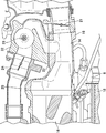
- FIG. 1 is a front view showing a portion on the intake side of an engine 1 according to an embodiment of the present invention
- FIG. 2 is a front view showing a portion on the intake side of the engine 1 according to an embodiment of the present invention in cross section.
- FIG. FIGS. 1 and 2 show the upper right portion of the engine 1 when the engine 1 is viewed from the front.
- the engine 1 is disposed between the engine body 2, an intake system 4 attached to the engine body 2, and the engine body 2 and the intake system 4.
- a fuel pump 6 for supplying fuel.
- the engine 1 is disposed in the vehicle in a state where the engine output shaft direction of the engine body 2 is in the width direction (lateral direction) of the vehicle. 1, the left-right direction in FIG. 1 is the engine output shaft direction of the engine 1, the up-down direction in FIG. 1 is the up-down direction of the vehicle and the engine 1, and in FIG. It is one forward direction.
- the engine body 2 includes a cylinder head 10 and a cylinder block 12 (see FIGS. 3 and 4).
- the intake system device 4 is disposed on the vehicle front side of the engine 1 and is connected to the inlet duct 14 as a first intake passage portion for introducing the intake air, and the inlet duct 14 to compress the intake air. 2)
- a supercharger 16 as an intake passage, an intercooler 18 for cooling the intake air discharged from the supercharger 16, and a branch from the inlet duct 14 are supplied directly to the engine body 2 without passing through the supercharger 16
- an air bypass passage 22 through which the intake air passes.
- the inlet duct 14 is formed of an aluminum alloy, and the flow passage direction thereof is disposed substantially parallel to the engine output shaft direction.
- the inlet duct 14 is formed so that the upper side extends toward the end connected to the supercharger 16 from substantially the center in the longitudinal direction, and the end connected to the supercharger 16 has a flange 20 doing.
- the inlet duct 14 is connected to the supercharger 16 via the flange 20.
- a throttle valve 21 is attached to an end of the inlet duct 14 opposite to the flange 20.
- a flange 23 (FIG. 2) as a connecting portion to which the air bypass passage 22 is connected is formed at the upper end portion of the circumferential surface of the inlet duct 14 substantially at the center in the longitudinal direction. The end of this flange 23 is connected in series to a flange 19 (FIG. 2) for mounting the throttle valve 21.
- the supercharger 16 is disposed such that the flow passage direction is substantially parallel to the engine output shaft direction.
- the intercooler 18 is connected to the supercharger 16 via a duct located below the supercharger 16 and extending downward from the supercharger 16. Further, the intercooler 18 is connected to the engine body 2 via a pipe so as to supply the cooled intake air to the engine body 2.
- the air bypass passage 22 is provided on the downstream side of the throttle valve 21 in the inlet duct 14 and is coupled to the flange 23 of the inlet duct 14.
- the air bypass passage 22 is provided with an air bypass valve 24 for opening and closing the air bypass passage 22, and an EGR passage (not shown) is connected upstream of the air bypass valve 24 to connect the EGR passage.
- the EGR valve 26 is disposed.
- the air bypass passage 22 extends upward from the inlet duct 14 and extends along the engine output shaft above the inlet duct 14 and the supercharger 16.
- the passage from the inlet duct 14 of the air bypass passage 22 to the EGR valve 26 is formed of aluminum alloy, and the passage from the air bypass valve 24 is formed of metal.
- the air bypass passage 22 is connected to the intake side of the engine body 2 at an end opposite to the side connected to the inlet duct 14. Therefore, the inlet duct 14 is attached to the engine body 2 via the air bypass passage 22.
- the intake passage portion of the present invention is configured including the intake passage of the inlet duct 14, the intake passage of the air bypass passage 22, the intake passage of the supercharger 16, and the intake passage of the intercooler 18.
- a radiator (not shown) for cooling the refrigerant of the intercooler 18 is provided on the vehicle front side of the intake system device 4.
- a space having a predetermined distance is provided between the radiator and the front end of the intake system 4, and no components are arranged in this space.
- the fuel pump 6 is located in front of the engine body 2 and behind the inlet duct 14 and the intercooler 18, as shown in FIGS. 1 and 2. That is, the fuel pump 6 is disposed between the engine body 2 and the intake system 4.
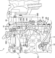
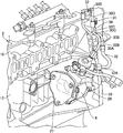
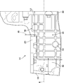
- FIG. 3 is a view showing the fuel pump 6 and the engine body 2 of the engine 1 according to an embodiment of the present invention
- FIG. 4 is a view showing the fuel pump 6 of the engine 1 according to an embodiment of the present invention. It is a perspective view which shows the state attached to.
- FIGS. 3 and 4 show a state in which the intake system device 4 is removed.
- the cylinder head 10 and the cylinder block 12 of the engine body 2 are formed at one end side (right side in FIG.
- a cover 25 (FIG. 3) covering the timing chain system of the engine 1 provided on the end face of the cylinder block 12 at one end side in the engine output shaft direction is attached to the engine body side flange portion 28.
- the fuel pump 6 is fixed to a side surface on the cylinder block 12 side of the engine body side flange portion 28 and on the other end side in the engine output shaft direction by a bolt 29 (FIG. 4). Further, a bracket 27 is attached to the side surface of the fuel pump 6 on the other end side in the engine output shaft direction, and the bracket 27 is fixed to the cylinder block 12. The fuel pump 6 is attached to the cylinder block 12 by the bolts 29 and the brackets 27.
- the fuel pump 6 is connected to a first fuel pipe 30 through which the fuel supplied from a fuel tank (not shown) passes, and a second fuel pipe 32 through which the fuel pressure-fed from the fuel pump 6 to the engine body 2 passes.
- the first and second fuel pipes 30, 32 both extend upward along the side surface of the cylinder block 12.
- the first fuel pipe 30 is connected to the upper end of the fuel pump 6 and one end side in the engine output shaft direction, and the engine on the cylinder head 10 side obliquely upward toward the engine body side flange portion 28
- a first portion 30A extending to the front of the main body flange portion 28 and a second portion 30B extending upward along the front surface of the engine main body flange portion 28 thereafter, again toward the other end side in the engine output shaft direction and the cylinder head 10
- a fourth portion 30D extending upward to the upper side of the engine main body 2 at the other end side of the engine main body side flange portion 28 in the engine output axial direction.
- the first fuel pipe 30 is fixed to the engine body 2 by fixing the fourth portion 30 ⁇ / b> C to the front surface of the engine body flange portion 28 via the bracket 31.
- the second fuel pipe 32 is connected to the upper side surface of the fuel pump 6 and one end side in the engine output shaft direction, and the engine output shaft of the engine body side flange portion 28 across the front surface of the engine body side flange portion 28
- the first part 32A extends to a position projecting to one end side from the one end side end face, and curves while returning to the other end side in the engine output shaft direction in the direction approaching the cylinder head 10 and then the engine body side flange portion 28 At a position on one end side of the engine output shaft, more specifically, in the front of the flange 25A of the cover 25 of the timing chain system, the second portion 32B extending upward and the engine output shaft across the front of the engine body side flange portion 28 again Extending to the other end side of the third portion 30C of the first fuel pipe 30, that is, the side closer to the engine body 2 A third portion 32C extending to the position, and a fourth portion 32D extending upward to the upper side of the engine body 2 at the other end side of the
- the second fuel pipe 32 is fixed to the engine body 2 by fixing the fourth portion 32D to the mounting portion on the upper surface of the cylinder head 10 via the bracket 33.
- the fuel system component of the present invention is configured to include the fuel pump 6 and the first and second fuel pipes 30, 32, and the fuel system component is adjacent to the engine body side flange portion 28. It is arranged.
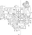
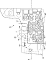
- FIG. 5 is a view of the inlet duct 14 and the fuel pump 6 according to an embodiment of the present invention as viewed from the engine body 2 side.
- the inlet duct 14 is disposed in front of the fuel pump 6, and is disposed in a vertical positional relationship such that the upper portion of the fuel pump 6 is positioned at the lower end of the inlet duct 14.
- the inlet duct 14 is disposed in a lateral positional relationship such that the upper portion of the fuel pump 6 is positioned near the flange 20 on the other end side of the inlet duct 14 in the engine output shaft direction.
- the first fuel pipe 30 is disposed such that the first portion 30A extends upward from below the inlet duct 14 at a position rearward of the inlet duct 14 and approximately in the center of the engine output shaft.
- the inlet duct 14 is disposed at a position rearward of the inlet duct 14 and closer to one end in the engine output shaft direction, that is, at a predetermined distance L1 from the end in the engine output shaft direction.
- L1 predetermined distance
- the inlet duct 14 is located at a position overlapping the upper portion of the fuel pump 6, the first fuel pipe 30, and the second fuel pipe 32 on the circumferential surface on the engine body 2 side. It has the fuel system parts corresponding part 34 which counters.
- 6 is a view of the inlet duct 14 according to an embodiment of the present invention as viewed from the side of the engine main body 2
- FIG. 7 is a side sectional view of the inlet duct 14 and the engine main body 2 according to an embodiment of the present invention It is.
- a rib 36 is formed in the fuel system component corresponding part 34.
- the ribs 36 extend at equal intervals along the central axis A direction (longitudinal direction) of the inlet duct 14 and the direction orthogonal thereto, and are formed in a grid shape as a whole. Further, as shown in FIG. 7, the inlet duct 14 is formed such that the thickness of the fuel system component corresponding portion 34 is larger than the peripheral surface of the other portion.
- the air bypass passage 22 is in a range from a position spaced a predetermined distance L1 from one end side in the engine output shaft direction to a position spaced a predetermined distance L2 from the other end side in the engine output shaft direction. It is formed over the range from the flange 23 to be coupled to the lower end portion of the circumferential surface of the inlet duct 14. Further, in the range from the other end side in the engine output shaft direction to the predetermined distance L2, the inlet duct 14 is formed to expand upward, so the rib 36 is located above the flange 23 for the air bypass passage 22. And the lower end portion of the circumferential surface of the inlet duct 14.
- an area 40 where the rib 36 is not provided is formed in a range from the end of the inlet duct 14 in the engine output shaft direction to the predetermined distance L1.
- the region 40 is disposed between the throttle valve 21 attached to the end of the inlet duct 14 and the fuel system parts counterpart 34 of the inlet duct 14.
- the flange 23 for the air bypass passage 22 is connected to the flange 19 for the throttle valve 21, whereby the flange 23 supports fuel system components across the region 40 with respect to the intake flow direction of the inlet duct 14. It is connected to a flange 19 which is a portion opposite to the portion 34.
- the circumferential surface on the front side of the inlet duct 14 is an area 42 (FIG.
- FIG. 8 is a plan sectional view of the inlet duct 14 and the engine body 2 according to an embodiment of the present invention.
- the front end portion 44 is positioned near the lower end of the outer periphery of the inlet duct 14, offset downward below the central axis A of the inlet duct 14. It extends horizontally. Accordingly, the wall thickness D in the direction in which the tip end portion 44 of the inlet duct 14 extends in the portion where the tip end portion 44 is provided is larger than the wall thickness in the radial direction of the inlet duct 14.
- the proximal end of the front end portion 44 is connected to the rib 36 of the inlet duct 14, more specifically, at a position where the rib 36 intersects. Therefore, although the regions 40 and 42 are disposed in the vicinity of the proximal end of the tip end 44, the rigidity is lower than that of the proximal end. Further, the rib 36 connected to the base end of the front end portion 44 extends from the base end of the front end portion 44 to the flange 20 along the longitudinal direction (the direction of the central axis A).
- the front end portion 44 projects toward the engine body 2 at a position between the first fuel pipe 30 and the second fuel pipe 32 of the fuel pump 6 as shown in FIGS. 5 and 8, and the engine body of the engine body 2. It is disposed at a position facing the front surface of the side flange portion 28. A space of a predetermined distance L3 is provided between the front end portion 44 and the front surface of the engine body side flange portion 28. Therefore, when the inlet duct 14 moves in the direction of the engine body, the front end portion 44 can contact the engine body side flange portion 28 of the engine body 2.
- the predetermined distance L3 is the distance from the outer surface of the inlet duct 14 to the outer periphery of the fuel pump 6, the distance from the outer surface of the inlet duct 14 to the first fuel pipe 30, and the second fuel pipe 32 from the outer surface of the inlet duct 14. It is set smaller than the distance to
- the radiator moves to the rear side of the vehicle due to the collision load. Since a space having a predetermined distance is provided between the radiator and the intake system 4 and no parts are arranged in this space, while the radiator is moving while absorbing the collision load, the other parts of the engine 1 are Parts are not damaged.
- the radiator moves beyond a predetermined distance from the intake system 4, the radiator contacts the intake system 4.
- the regions 40 and 42 which are fragile parts of the inlet duct 14, are broken and absorb the collision load. Further, depending on the magnitude of the collision load, the portion between the flange 23 and the rib 36 of the inlet duct 14 is also broken. On the other hand, since the ribs 36 are formed in the fuel system component corresponding portion 34, the rigidity is higher than in the regions 40 and 42, thereby preventing the breakage. Thus, the inlet duct 14 is broken at the position indicated by the two-dot chain line 45 in FIG.
- the fuel system component corresponding part 34 extends to the flange 20
- the fuel system component corresponding part 34 is connected to the flange 20
- the flange 23 connects the throttle valve 21.
- the flange 19 is connected to the throttle valve 21, and the flange 23 is connected to the air bypass passage 22. Since the air bypass passage 22 is connected to the engine body 2, the throttle valve 21 is supported by the engine body 2 via the air bypass passage 22. Therefore, when the regions 40 and 42 are destroyed, the connection between the throttle valve 21 and the air bypass passage 22 and the fuel system component counterpart 34 and the supercharger 16 is released. Therefore, no further collision load is input to the throttle valve 21 or the air bypass passage 22.
- the front end portion 44 protruding from the fuel system component corresponding portion 34 abuts on the engine body side flange portion 28 to prevent further movement of the inlet duct 14 Do.
- the distance L3 between the tip of the front end portion 44 and the engine body side flange portion 28 is the distance from the outer surface of the inlet duct 14 to the outer periphery of the fuel pump 6, and the first fuel pipe 30 from the outer surface of the inlet duct 14.
- the inlet duct 14 reaches the fuel pump 6, the first fuel pipe 30, or the second fuel pipe 32 because it is set smaller than the distance up to and the distance from the outer surface of the inlet duct 14 to the second fuel pipe 32.
- the tip end portion 44 abuts on the engine body side flange portion 28. As described above, the collision load is absorbed, and damage to fuel system components such as the fuel pump 6, the first fuel pipe 30, and the second fuel pipe 32 is avoided.
- the ribs 36 are provided in the fuel system component corresponding portion 34, and the ribs are not provided in the regions 40 and 42, the regions 40 and 42 have a fragile portion whose rigidity is lower than that of the fuel system component corresponding portion 34 Become. Therefore, when a collision load at the time of a collision of a vehicle is input to inlet duct 14, regions 40 and 42 are destroyed earlier than fuel system component corresponding part 34, and the collision load is absorbed. As a result, the transmission of the collision load to the fuel system component corresponding unit 34 can be prevented, and the fuel system component corresponding unit 34 is not broken. Therefore, the fuel pump 6, the first and second fuel pipes 30, 32 and so on It can protect fuel system parts.
- the fuel system parts corresponding portion 34 of the inlet duct 14 can be provided with the ribs 36 to protect the fuel system parts, so there is a sufficient space between the intake passage section such as the inlet duct 14 and the fuel system parts. Even if it can not be ensured, fuel system parts can be reliably protected in the event of a vehicle collision.
- the fragile portions are formed in the areas 40 and 42 by providing the ribs 36 in the fuel system component corresponding part 34 and not forming the ribs in the areas 40 and 42, the number, shape, arrangement, etc. of the ribs to be formed are adjusted. Thus, the rigidity of the fuel system component corresponding part 34 can be easily adjusted.
- the flange 23 for connecting to the air bypass passage 22 in the inlet duct 14 is connected to the flange 19 for connecting the throttle valve 21. Therefore, when the area 40, 42 is broken by the collision load of the vehicle, the throttle The valve 21 is connected to and supported by the air bypass passage 22 via the flange 19 of the inlet duct 14. Therefore, even when the regions 40 and 42 are destroyed and the connection between the throttle valve 21 and the inlet duct 14 is released, it is possible to prevent problems such as the throttle valve 21 losing support and colliding with peripheral parts.
- the regions 40 and 42 are disposed between the throttle valve 21 and the fuel system parts corresponding portion 34, when the collision load is input to the inlet duct 14, the regions 40 and 42 are broken and the inlet duct 14 and the throttle The connection with the valve 21 is released. Therefore, the collision load input to the inlet duct 14 can be prevented from being transmitted to the throttle valve 21, and damage to the throttle valve 21 can be prevented.
- the front end portion 44 protrudes toward the engine body 2 at a position between the first fuel pipe 30 and the second fuel pipe 32, the first fuel pipe 30 and the second fuel pipe when viewed from the front of the vehicle It is formed at a position not overlapping 32. Therefore, when the inlet duct 14 moves toward the engine body 2 at the time of a collision of the vehicle, the tip end portion 44 is earlier than the inlet duct 14 abuts on the engine body 2 and the first and second fuel pipes 30 and 32. Can be in contact with the engine body 2 to protect the first and second fuel pipes 30, 32.
- the front end portion 44 Since the base end of the front end portion 44 is provided at a position where the plurality of ribs 36 intersect, the front end portion 44 is formed in a portion with higher rigidity. When in contact, damage to the tip end 44 from the proximal end is suppressed. Therefore, the first and second fuel pipes 30, 32 can be protected more reliably.
- At least one rib 36 of the plurality of ribs 36 extends to connect the proximal end portion of the tip end 44 and the flange 20.
- the rib 36 extends so as to connect the proximal end portion of the front end portion 44 and the flange 20.
- the rigidity of the inlet duct 14 of the portion is increased. Therefore, when the front end portion 44 abuts on the engine body 2, the inlet duct 14 around the front end portion 44 is less likely to be damaged, and the first and second fuel pipes 30, 32 can be protected more reliably. .
- the present invention is not limited to the above embodiment, and may be, for example, the following aspect.
- the rib 36 is provided in the fuel system component corresponding portion 34 and the rib is not provided in the regions 40 and 42 to form the fragile portion in the regions 40 and 42
- ribs are formed on both the fuel system parts corresponding part and the area adjacent to the fuel system parts corresponding area, and the number of ribs of the fuel system parts corresponding area is larger than the number of ribs on the area adjacent to this.
- the method of forming the fragile portion at least one rib may be formed in the fuel system component corresponding portion, and the number of ribs in the fuel system component corresponding portion may be set larger than the number of ribs provided in the fragile portion .
- the method of forming the fragile portion sets the rib formation interval of the fuel system component correspondence section smaller than the rib formation interval of the adjacent section, and the thickness of the fuel system component correspondence section is greater than the thickness of the adjacent section
- any formation method and structure can be adopted such as setting the thickness thick.
- the position, arrangement, range, and the like of the fragile portion can be appropriately changed according to the arrangement of the intake passage portion with respect to the engine main body and the arrangement with respect to the fuel system components.
- the fragile portion may not necessarily be provided, for example, between a valve such as a throttle valve and an intake passage such as an inlet duct.
- FIG. 9 is a view of an inlet duct 46 according to a modification of the present invention as viewed from the engine body side.
- the fuel system component corresponding portion 48 of the inlet duct 46 has ribs 50, but the ribs 50 are formed in a diagonal on the inside of the grid in addition to the grid pattern, truss It is configured as a rib.
- the rib 50 is not connected to the flange 52 for the air bypass passage 22 and is formed from below. Therefore, the fragile portion 53 is formed on the outer peripheral portion of the portion provided with the rib 50, more specifically, above the portion provided with the rib 50 and the portion on the flange 55 side for the throttle valve.
- the inlet duct 46 is broken at the position of the two-dot chain line 54 as in the inlet duct 14 of the above-described embodiment.
- Ru According to such a shape of the rib 50, since the rib 50 is not connected to the flange 52, even when the input load to the fragile portion is large, when the inlet duct 46 is broken at the position of the two-dot chain line 54, Stress is less likely to be applied to the fuel system parts corresponding part.
- the shape and arrangement of the ribs can be set arbitrarily.
- the front end portion is not limited to a cylindrical shape, and may be a square pole such as a square pole as shown in the front end portion 56 of FIG. 9, for example.
- the shape of the tip end can be set arbitrarily.
- the flange 23 for the air bypass passage 22 is connected to the flange 19 for the throttle valve 21.
- the connecting portion for attaching the intake passage portion to the engine body is not necessarily required. With respect to the intake flow direction of the intake passage portion, it may not be connected to a portion opposite to the fuel system component corresponding portion across the fragile portion.
- the fragile portion is provided between the throttle valve 21 and the fuel system component corresponding portion 34 of the inlet duct 14, but the invention is not limited thereto.
- Other valves such as an EGR valve and an air bypass valve
- the valve may be any valve for controlling the amount of intake air supplied to the engine body.
- the fuel system parts corresponding part is the surface of the inlet duct 14 on the side of the engine main body 2 in the above embodiment, but the invention is not limited to this, and it may be set in any intake passage such as an air bypass passage or a supercharger.
Abstract
An engine 1 comprises: an engine body 2 that includes a cylinder head 10 and a cylinder block 12; an inlet duct 14 attached to the engine body 2; and a fuel system component disposed between the engine body 2 and the inlet duct 14. The inlet duct 14 is disposed so as to be located on the vehicle-front side of the engine body 2 when mounted in a vehicle and comprises a fuel system component accommodating section 34, disposed at a position so as to overlap with the fuel system component when viewed from the front side of the vehicle, and regions 40, 42 that are adjacent to the fuel system component accommodating section 34 and have lower rigidity than the fuel system component accommodating section 34.
Description
本発明は、エンジン本体と、エンジン本体に取り付けられた吸気通路部とを有するエンジンに関する。
The present invention relates to an engine having an engine body and an intake passage portion attached to the engine body.
従来、エンジン本体の車両前方側に吸気装置を配置したエンジンがある。例えば特許文献1に記載されたエンジンでは、エンジン本体の車両前方側に吸気管、吸気マニホールド及び吸気導入管等の吸気装置が配置され、エンジン本体と吸気装置との間にはオイルセパレータが配置されている。このようなエンジンでは、車両の衝突時に吸気装置がエンジン本体側に移動してオイルセパレータを損傷しないように、吸気装置側に突出板で構成された荷重伝達部を設け、オイルセパレータ側に荷重伝達部からの荷重を受ける荷重受け部材を設けて、オイルセパレータを保護している。
Conventionally, there is an engine in which an intake system is disposed on the vehicle front side of an engine body. For example, in the engine described in Patent Document 1, an intake device such as an intake pipe, an intake manifold, and an intake introduction pipe is disposed on the vehicle front side of the engine body, and an oil separator is disposed between the engine body and the intake device. ing. In such an engine, a load transfer unit constituted by a projecting plate is provided on the intake device side so that the intake device does not move to the engine body side and damage the oil separator in the event of a vehicle collision, and load transfer on the oil separator side A load receiving member for receiving a load from the unit is provided to protect the oil separator.
しかしながら、近年、エンジン本体の車両前方側により多くの部品が配置されるようになり、そのため、エンジン本体の車両前方側により多くのスペースが必要となっている。しかしながらその一方で、車両前方側の部品の前方側には、所定距離をあけてラジエータが配置されており、車両の衝突時には、ラジエータがこの所定距離を移動することによって衝突荷重を吸収するようになっている。よって、車両前方側の部品とラジエータとの間にはこの所定距離を確保する必要があり、エンジン本体の車両前方側に自由に大きなスペースを確保できるわけではない。このような状況下では、上記特許文献1のように吸気装置及びオイルセパレータの両方から突出する部材を吸気装置とエンジン本体との間に配置するスペースがなく、オイルセパレータのような燃料系部品の保護を図ることが難しいという問題がある。
However, in recent years, more parts are disposed on the vehicle front side of the engine body, and therefore, more space is required on the vehicle front side of the engine body. However, on the other hand, a radiator is disposed at a predetermined distance on the front side of the front part of the vehicle, and in the event of a vehicle collision, the radiator moves the predetermined distance to absorb the collision load. It has become. Therefore, it is necessary to secure the predetermined distance between the part on the vehicle front side and the radiator, and a large space can not be freely secured on the vehicle front side of the engine body. Under such circumstances, there is no space for arranging a member projecting from both the intake device and the oil separator between the intake device and the engine body as in Patent Document 1 described above, and a fuel system component such as an oil separator There is a problem that it is difficult to protect.
本発明の目的は、燃料系部品がエンジン本体と吸気通路部との間に配設されている場合であっても、車両衝突時の燃料系部品の保護を図ることができるエンジンを提供することにある。
An object of the present invention is to provide an engine capable of protecting fuel system components in the event of a vehicle collision, even when the fuel system components are disposed between the engine body and the intake passage section. It is in.
上記の目的を達成するために、本発明のエンジンは、シリンダヘッド及びシリンダブロックを含むエンジン本体と、エンジン本体に取り付けられる吸気通路部と、エンジン本体と吸気通路部との間に配設された燃料系部品と、を有するエンジンであって、吸気通路部は、車両に搭載された状態においてエンジン本体の車両前方側に位置するように配置されるとともに、車両前方側から見たときに燃料系部品に重なる位置に配置された燃料系部品対応部と、燃料系部品対応部に隣接して配置され且つ燃料系部品対応部よりも剛性が低い脆弱部と、を有する、ことを特徴としている。
In order to achieve the above object, the engine of the present invention is disposed between an engine body including a cylinder head and a cylinder block, an intake passage portion attached to the engine body, and an engine body and an intake passage portion. An engine having a fuel system component, wherein the intake passage portion is disposed on the vehicle front side of the engine body in a state mounted on the vehicle, and the fuel system when viewed from the vehicle front side A fuel system component corresponding portion disposed at a position overlapping the component and a fragile portion disposed adjacent to the fuel system component corresponding portion and having a rigidity lower than that of the fuel system component corresponding portion are characterized.
このように構成された本発明においては、エンジン本体の車両前方側に配置された吸気通路部が、車両前方側から見たときに燃料系部品に重なる燃料系部品対応部を有し、燃料系部品対応部に隣接した位置には、脆弱部が形成されている。脆弱部は、燃料系部品対応部よりも剛性が低くなっているので、車両の衝突時に吸気通路部が衝突荷重を受けた場合、燃料系部品対応部よりも先に、燃料系部品対応部に隣接する脆弱部がまず破損し、衝突荷重を吸収する。したがって、燃料系部品に対応する部分への衝突荷重の伝達が抑制され、吸気通路部と燃料系部品との部品の衝突が回避される。本発明では、吸気通路部自体に脆弱部を設けることにより、従来のような荷重受け部材を吸気通路部と燃料系部品との間に設ける必要がない。したがって、燃料系部品がエンジン本体と吸気通路部の間に配置されて、吸気通路部と燃料系部品との間に十分なスペースが確保できない場合であっても、車両衝突時に燃料系部品が保護される。
In the present invention thus configured, the intake passage portion disposed on the vehicle front side of the engine body has a fuel system component corresponding portion overlapping the fuel system component when viewed from the vehicle front side, and the fuel system A fragile portion is formed at a position adjacent to the component corresponding portion. The fragile portion is lower in rigidity than the fuel system component corresponding section, so if the intake passage section receives a collision load at the time of a collision of the vehicle, the fuel system component corresponding section is earlier than the fuel system component corresponding section. The adjacent fragile part breaks first and absorbs the collision load. Therefore, the transmission of the collision load to the portion corresponding to the fuel system component is suppressed, and the collision of the component between the intake passage portion and the fuel system component is avoided. In the present invention, by providing the weak portion in the intake passage itself, it is not necessary to provide a conventional load receiving member between the intake passage and the fuel system component. Therefore, even if a fuel system component is disposed between the engine body and the intake passage section and a sufficient space can not be secured between the intake passage section and the fuel system component, the fuel system component is protected in the event of a vehicle collision. Be done.
本発明において、好ましくは、燃料系部品対応部には、少なくとも1つのリブが設けられ、リブの数は、脆弱部に設けられたリブの数よりも多い。
このように構成された本発明においては、燃料系部品対応部に少なくとも1つのリブが設けられているので、燃料系部品対応部の剛性が高くなる。一方、燃料系部品対応部に設けられたリブの数は、脆弱部に設けられたリブの数よりも多いので、燃料系部品対応部は脆弱部よりも剛性が高くなる。本発明では、燃料系部品対応部あるいは燃料系部品対応部及び脆弱部の両方にリブを形成してその数を調整することにより容易に剛性の調整が可能となる。 In the present invention, preferably, the fuel system component corresponding part is provided with at least one rib, and the number of ribs is larger than the number of ribs provided in the fragile part.
In the present invention configured as described above, at least one rib is provided in the fuel system component corresponding portion, so the rigidity of the fuel system component corresponding portion is increased. On the other hand, since the number of ribs provided in the fuel system component corresponding portion is larger than the number of ribs provided in the fragile portion, the fuel system component corresponding portion has higher rigidity than the fragile portion. In the present invention, the rigidity can be easily adjusted by forming ribs on both the fuel system component corresponding part or both the fuel system component corresponding part and the fragile part and adjusting the number thereof.
本発明において、好ましくは、吸気通路部は、吸気通路部をエンジン本体に取り付けるための連結部を有し、連結部は、吸気通路部の吸気流れ方向に関して、脆弱部を挟んで燃料系部品対応部とは反対側の部分に接続されている。
このように構成された本発明においては、吸気通路部は、連結部によってエンジン本体に取り付けられている。ここで、連結部は、吸気通路部の吸気流れ方向に関して、脆弱部を挟んで燃料系部品対応部とは反対側の部分に接続されている。したがって、車両の衝突時に吸気通路部に衝突荷重が伝達されると、脆弱部が先に破損するが、このとき、燃料系部品対応部とは反対側の部分が連結部によって支持される。連結部はエンジン本体に取り付けられているので、燃料系部品対応部とは反対側の部分が、間接的にエンジン本体に支持されるから、当該部分が周辺部品に衝突するのが回避される。 In the present invention, preferably, the intake passage portion has a connection portion for attaching the intake passage portion to the engine main body, and the connection portion supports the fuel system parts across the fragile portion in the intake flow direction of the intake passage portion. It is connected to the part opposite to the part.
In the present invention configured as described above, the intake passage portion is attached to the engine body by the connection portion. Here, the connecting portion is connected to a portion on the opposite side to the fuel system component corresponding portion across the fragile portion in the intake flow direction of the intake passage portion. Therefore, when the collision load is transmitted to the intake passage at the time of a collision of the vehicle, the fragile portion is damaged first, but at this time, the portion opposite to the fuel system component corresponding portion is supported by the connecting portion. Since the connecting portion is attached to the engine body, the portion opposite to the fuel system component corresponding portion is indirectly supported by the engine body, so that the collision of the portion with peripheral parts is avoided.
本発明において、好ましくは、吸気通路部には、エンジン本体へ供給される吸気量をコントロールするためのバルブが設けられ、脆弱部は、燃料系部品対応部とバルブとの間に配置されている。
このように構成された本発明においては、脆弱部が燃料系部品対応部とバルブとの間に配置されているので、車両の衝突時に衝突荷重が伝達されると、燃料系部品対応部とバルブとの間の脆弱部がまず破損し、燃料系部品対応部とバルブとの連結が解消される。したがって、衝突荷重がバルブに伝達されるのが抑制され、バルブが保護される。 In the present invention, preferably, the intake passage portion is provided with a valve for controlling the intake amount supplied to the engine body, and the fragile portion is disposed between the fuel system component corresponding portion and the valve .
In the present invention configured as described above, since the fragile portion is disposed between the fuel system component corresponding section and the valve, when a collision load is transmitted at the time of a vehicle collision, the fuel system component corresponding section and the valve The fragile part between them is broken first, and the connection between the fuel system part corresponding part and the valve is released. Thus, the transfer of the collision load to the valve is suppressed and the valve is protected.
本発明において、好ましくは、燃料系部品は、燃料配管であり、燃料系部品対応部からエンジン本体に向かって突出する先当て部を有し、先当て部は、車両前方から見たときに燃料配管と重ならない位置に形成されている。
このように構成された本発明においては、先当て部が車両前方から見たときに燃料配管と重ならない位置に形成されているので、車両の衝突時に吸気通路部がエンジン本体に向かって移動すると、先当て部がエンジン本体に当接して、燃料配管が保護される。 In the present invention, preferably, the fuel system component is a fuel pipe, and has a tip end projecting toward the engine body from the fuel base component corresponding portion, and the tip end is a fuel when viewed from the front of the vehicle It is formed at a position not overlapping with the piping.
In the present invention configured as described above, since the front end portion is formed at a position not overlapping the fuel pipe when viewed from the front of the vehicle, when the intake passage portion moves toward the engine main body when the vehicle collides The tip end portion abuts on the engine body to protect the fuel pipe.
本発明において、好ましくは、燃料系部品対応部は、互いに交差して形成された複数のリブを有し、先当て部の基端部は、複数のリブが交差する位置に設けられている。
このように構成された本発明においては、先当て部の基端部が、複数のリブが交差する位置に設けられているので、先当て部がより剛性の高い部分に形成されるから、先当て部がエンジン本体に当接したときに、先当て部が基端部から損傷するのが抑制される。したがって、燃料配管がより確実に保護される。 In the present invention, preferably, the fuel system component corresponding portion has a plurality of ribs formed to intersect with each other, and the base end portion of the tip end portion is provided at a position where the plurality of ribs intersect.
In the present invention configured as described above, since the base end portion of the tip end portion is provided at the position where the plurality of ribs intersect, the tip end portion is formed in a portion with higher rigidity. When the abutment portion abuts on the engine body, damage to the tip end portion from the proximal end portion is suppressed. Therefore, fuel piping is protected more reliably.
本発明において、好ましくは、吸気通路部は、エンジン本体の車両前方側に配置されたスーパーチャージャにフランジを介して接続され、複数のリブのうち、少なくとも1つのリブは先当て部の基端部とフランジを接続するように延びている。
このように構成された本発明においては、複数のリブのうち、少なくとも1つのリブは、先当て部の基端部とフランジを接続するように延びている。ここで、フランジは、比較的剛性の高い部分であるので、リブが先当て部の基端部とフランジとを接続するように延びることにより、先当て部からフランジまでの部分の吸気通路部の剛性が高くなる。よって先当て部がエンジン本体に当接したときに先当て部の周りの吸気通路部が破損しにくくなり、より確実に燃料配管が保護される。 In the present invention, preferably, the intake passage portion is connected via a flange to a supercharger disposed on the vehicle front side of the engine body, and at least one of the plurality of ribs is a proximal end portion of the tip end portion And it extends to connect the flange.
In the present invention thus configured, at least one rib of the plurality of ribs extends to connect the proximal end portion of the tip end portion and the flange. Here, since the flange is a relatively rigid portion, the rib extends so as to connect the proximal end portion of the tip end portion and the flange, so that the intake passage portion of the portion from the tip end portion to the flange The rigidity is high. Therefore, when the tip end portion abuts on the engine body, the intake passage portion around the tip end portion is less likely to be damaged, and the fuel piping is more reliably protected.
また、上記の目的を達成するために、本発明のエンジンは、シリンダヘッド及びシリンダブロックを含むエンジン本体と、エンジン本体に取り付けられる吸気通路部と、エンジン本体と吸気通路部との間において、該吸気通路に沿って配設された燃料配管と、を有し、吸気通路部は、車両に搭載された状態においてエンジン本体の車両前方側に位置するように配置され、吸気通路部の燃料配管側の部分は、車両前方側から見たときに燃料配管と重なる位置において、周囲の領域よりも剛性を高めるべく設けられた複数のリブが互いに交差して形成され、該複数のリブが交差する位置からエンジン本体方向に向けて突出する先当て部を有し、該先当て部は、車両前方側から見たときに、燃料配管と重ならない位置に設けられている、ことを特徴としている。
Further, in order to achieve the above object, the engine of the present invention includes an engine body including a cylinder head and a cylinder block, an intake passage portion attached to the engine body, and an engine body and an intake passage portion. And a fuel pipe disposed along the intake passage, the intake passage portion being disposed on the vehicle front side of the engine body in a state mounted on the vehicle, and the fuel piping side of the intake passage portion At a position where the portion of the overlap with the fuel piping when viewed from the front side of the vehicle, a plurality of ribs provided to increase rigidity more than the surrounding area are formed to intersect with each other, and the plurality of ribs intersect It has a tip which protrudes from the engine toward the engine body, and the tip is provided at a position not overlapping the fuel piping when viewed from the vehicle front side. It is set to.
このように構成された本発明においては、吸気通路部の燃料配管側の部分は、車両前方側から見たときに燃料配管と重なる位置において、周囲の領域よりも剛性を高めるべく設けられた複数のリブが高いに交差して形成され、先当て部が、複数のリブが交差する位置からエンジン本体方向に向けて突出するように設けられているので、車両の衝突時に吸気通路部がエンジン本体側に移動したとき、先当て部がエンジン本体に当接して燃料配管を保護する。このとき、先当て部が複数のリブが交差する位置からエンジン本体方向に向けて突出するように設けられているので、先当て部がエンジン本体に当接したときに、先当て部が基端部から損傷するのが抑制される。したがって、燃料配管がより確実に保護される。
また、先当て部が車両前方から見たときに燃料配管と重ならない位置に形成されているので、車両の衝突時に吸気通路部がエンジン本体に向かって移動すると、先当て部がエンジン本体に当接することにより、燃料配管が保護される。 In the present invention configured as described above, the portion on the fuel pipe side of the intake passage portion is provided with a plurality of portions provided to have higher rigidity than the surrounding region at the position overlapping the fuel pipe when viewed from the vehicle front side. The rib is formed to cross at a high level, and the tip end portion is provided to project toward the engine body from the position where the ribs intersect, so that the intake passage portion becomes the engine body at the time of a vehicle collision. When moving to the side, the front end contacts the engine body to protect the fuel piping. At this time, since the tip end portion is provided to project in the direction of the engine main body from the position where the plurality of ribs intersect, when the tip end portion abuts on the engine main body, the tip end portion is proximal Damage from the part is suppressed. Therefore, fuel piping is protected more reliably.
Further, since the front end portion is formed at a position not overlapping the fuel pipe when viewed from the front of the vehicle, when the intake passage portion moves toward the engine main body at the time of a vehicle collision, the front end portion contacts the engine main body The fuel piping is protected by the contact.
本発明において、好ましくは、吸気通路部は、エンジン本体の車両前方側に配置されたスーパーチャージャにフランジを介して接続され、複数のリブのうち、少なくとも1つのリブは先当て部の基端部とフランジとを接続するように延びている。
このように構成された本発明においては、複数のリブのうち、少なくとも1つのリブは、先当て部の基端部とフランジを接続するように延びている。ここで、フランジは、比較的剛性の高い部分であるので、リブが先当て部の基端部とフランジとを接続するように延びることにより、先当て部からフランジまでの部分の吸気通路部の剛性が高くなる。よって先当て部がエンジン本体に当接したときに先当て部の周りの吸気通路部が破損しにくくなり、より確実に燃料配管が保護される。 In the present invention, preferably, the intake passage portion is connected via a flange to a supercharger disposed on the vehicle front side of the engine body, and at least one of the plurality of ribs is a proximal end portion of the tip end portion It extends to connect the and the flange.
In the present invention thus configured, at least one rib of the plurality of ribs extends to connect the proximal end portion of the tip end portion and the flange. Here, since the flange is a relatively rigid portion, the rib extends so as to connect the proximal end portion of the tip end portion and the flange, so that the intake passage portion of the portion from the tip end portion to the flange The rigidity is high. Therefore, when the tip end portion abuts on the engine body, the intake passage portion around the tip end portion is less likely to be damaged, and the fuel piping is more reliably protected.
以下、本発明の好ましい実施形態を添付図面を参照して説明する。
図1は、本発明の一実施形態に係るエンジン1の吸気側の部分を示す正面図であり、図2は、本発明の一実施形態に係るエンジン1の吸気側の部分を断面で示す正面図である。これらの図1及び図2は、エンジン1を正面から見たときの、エンジン1の右側上部の部分を示している。図1及び図2に示すように、エンジン1は、エンジン本体2と、エンジン本体2に取り付けられた吸気系装置4と、エンジン本体2と吸気系装置4との間に配置されエンジン本体2に燃料を供給する燃料ポンプ6と、を有する。 Hereinafter, preferred embodiments of the present invention will be described with reference to the attached drawings.
FIG. 1 is a front view showing a portion on the intake side of an engine 1 according to an embodiment of the present invention, and FIG. 2 is a front view showing a portion on the intake side of the engine 1 according to an embodiment of the present invention in cross section. FIG. FIGS. 1 and 2 show the upper right portion of the engine 1 when the engine 1 is viewed from the front. As shown in FIGS. 1 and 2, the engine 1 is disposed between theengine body 2, an intake system 4 attached to the engine body 2, and the engine body 2 and the intake system 4. And a fuel pump 6 for supplying fuel.
図1は、本発明の一実施形態に係るエンジン1の吸気側の部分を示す正面図であり、図2は、本発明の一実施形態に係るエンジン1の吸気側の部分を断面で示す正面図である。これらの図1及び図2は、エンジン1を正面から見たときの、エンジン1の右側上部の部分を示している。図1及び図2に示すように、エンジン1は、エンジン本体2と、エンジン本体2に取り付けられた吸気系装置4と、エンジン本体2と吸気系装置4との間に配置されエンジン本体2に燃料を供給する燃料ポンプ6と、を有する。 Hereinafter, preferred embodiments of the present invention will be described with reference to the attached drawings.
FIG. 1 is a front view showing a portion on the intake side of an engine 1 according to an embodiment of the present invention, and FIG. 2 is a front view showing a portion on the intake side of the engine 1 according to an embodiment of the present invention in cross section. FIG. FIGS. 1 and 2 show the upper right portion of the engine 1 when the engine 1 is viewed from the front. As shown in FIGS. 1 and 2, the engine 1 is disposed between the
エンジン1は、本実施形態では、車両に搭載された状態において、エンジン本体2のエンジン出力軸方向が車両の幅方向に(横方向)に沿って配置されている。図1においては、図1の左右方向がエンジン1のエンジン出力軸方向であり、図1の上下方向が車両及びエンジン1の上下方向であり、図1において紙面に直交する方向手前側が車両及びエンジン1の前方向である。
エンジン本体2は、シリンダヘッド10とシリンダブロック12(図3及び図4参照)と、を含む。 In the embodiment, the engine 1 is disposed in the vehicle in a state where the engine output shaft direction of theengine body 2 is in the width direction (lateral direction) of the vehicle. 1, the left-right direction in FIG. 1 is the engine output shaft direction of the engine 1, the up-down direction in FIG. 1 is the up-down direction of the vehicle and the engine 1, and in FIG. It is one forward direction.
Theengine body 2 includes a cylinder head 10 and a cylinder block 12 (see FIGS. 3 and 4).
エンジン本体2は、シリンダヘッド10とシリンダブロック12(図3及び図4参照)と、を含む。 In the embodiment, the engine 1 is disposed in the vehicle in a state where the engine output shaft direction of the
The
吸気系装置4は、エンジン1の車両前方側に配置されており、吸気を導入するための第1吸気通路部としてのインレットダクト14と、インレットダクト14に連結されて吸気を圧縮するための第2吸気通路部としてのスーパーチャージャ16と、スーパーチャージャ16から排出された吸気を冷却するインタークーラ18と、インレットダクト14から分岐して、スーパーチャージャ16を通らずに直接エンジン本体2に供給される吸気が通過するエアバイパス通路22と、を有する。
The intake system device 4 is disposed on the vehicle front side of the engine 1 and is connected to the inlet duct 14 as a first intake passage portion for introducing the intake air, and the inlet duct 14 to compress the intake air. 2) A supercharger 16 as an intake passage, an intercooler 18 for cooling the intake air discharged from the supercharger 16, and a branch from the inlet duct 14 are supplied directly to the engine body 2 without passing through the supercharger 16 And an air bypass passage 22 through which the intake air passes.
インレットダクト14は、アルミニウム合金で形成され、その流路方向がエンジン出力軸方向にほぼ平行に配置されている。インレットダクト14は、長さ方向略中央からスーパーチャージャ16に連結される側の端部に向かって上方側が広がるように形成され、スーパーチャージャ16に連結される側の端部にはフランジ20を有している。インレットダクト14は、このフランジ20を介してスーパーチャージャ16に接続されている。インレットダクト14のフランジ20とは反対側の端部には、スロットルバルブ21が取り付けられている。また、インレットダクト14の長手方向略中央の周面上端部分には、エアバイパス通路22が連結される連結部としてのフランジ23(図2)が形成されている。このフランジ23の端部は、スロットルバルブ21を取り付けるためのフランジ19(図2)に連続して接続している。
The inlet duct 14 is formed of an aluminum alloy, and the flow passage direction thereof is disposed substantially parallel to the engine output shaft direction. The inlet duct 14 is formed so that the upper side extends toward the end connected to the supercharger 16 from substantially the center in the longitudinal direction, and the end connected to the supercharger 16 has a flange 20 doing. The inlet duct 14 is connected to the supercharger 16 via the flange 20. A throttle valve 21 is attached to an end of the inlet duct 14 opposite to the flange 20. Further, a flange 23 (FIG. 2) as a connecting portion to which the air bypass passage 22 is connected is formed at the upper end portion of the circumferential surface of the inlet duct 14 substantially at the center in the longitudinal direction. The end of this flange 23 is connected in series to a flange 19 (FIG. 2) for mounting the throttle valve 21.
スーパーチャージャ16は、その流路方向がエンジン出力軸方向にほぼ平行に配置されている。
インタークーラ18は、スーパーチャージャ16の下方に位置するとともにスーパーチャージャ16から下方向に延びるダクトを介してスーパーチャージャ16に連結している。また、インタークーラ18は、冷却した吸気をエンジン本体2に供給するように、エンジン本体2に配管を介して接続されている。 Thesupercharger 16 is disposed such that the flow passage direction is substantially parallel to the engine output shaft direction.
Theintercooler 18 is connected to the supercharger 16 via a duct located below the supercharger 16 and extending downward from the supercharger 16. Further, the intercooler 18 is connected to the engine body 2 via a pipe so as to supply the cooled intake air to the engine body 2.
インタークーラ18は、スーパーチャージャ16の下方に位置するとともにスーパーチャージャ16から下方向に延びるダクトを介してスーパーチャージャ16に連結している。また、インタークーラ18は、冷却した吸気をエンジン本体2に供給するように、エンジン本体2に配管を介して接続されている。 The
The
エアバイパス通路22は、図2に示すように、インレットダクト14においてスロットルバルブ21の下流側に設けられ、インレットダクト14のフランジ23に結合されている。エアバイパス通路22には、エアバイパス通路22を開閉するエアバイパスバルブ24が設けられている他、エアバイパスバルブ24よりも上流側には、EGR通路(図示せず)が接続され、EGR通路にはEGRバルブ26が配置されている。
As shown in FIG. 2, the air bypass passage 22 is provided on the downstream side of the throttle valve 21 in the inlet duct 14 and is coupled to the flange 23 of the inlet duct 14. The air bypass passage 22 is provided with an air bypass valve 24 for opening and closing the air bypass passage 22, and an EGR passage (not shown) is connected upstream of the air bypass valve 24 to connect the EGR passage. The EGR valve 26 is disposed.
エアバイパス通路22は、インレットダクト14から上方に延び、インレットダクト14及びスーパーチャージャ16の上方において、エンジン出力軸方向に沿って延びている。なお、エアバイパス通路22のインレットダクト14からEGRバルブ26までの通路はアルミニウム合金で形成され、エアバイパスバルブ24から先の通路は金属で形成されている。
エアバイパス通路22は、インレットダクト14に接続する側とは反対側の端部においてエンジン本体2の吸気側に接続されている。したがって、インレットダクト14は、エアバイパス通路22を介してエンジン本体2に取り付けられていることになる。
本実施形態では、インレットダクト14の吸気通路、エアバイパス通路22の吸気通路、スーパーチャージャ16の吸気通路、及びインタークーラ18の吸気通路を含んで、本発明の吸気通路部が構成されている。 Theair bypass passage 22 extends upward from the inlet duct 14 and extends along the engine output shaft above the inlet duct 14 and the supercharger 16. The passage from the inlet duct 14 of the air bypass passage 22 to the EGR valve 26 is formed of aluminum alloy, and the passage from the air bypass valve 24 is formed of metal.
Theair bypass passage 22 is connected to the intake side of the engine body 2 at an end opposite to the side connected to the inlet duct 14. Therefore, the inlet duct 14 is attached to the engine body 2 via the air bypass passage 22.
In the present embodiment, the intake passage portion of the present invention is configured including the intake passage of theinlet duct 14, the intake passage of the air bypass passage 22, the intake passage of the supercharger 16, and the intake passage of the intercooler 18.
エアバイパス通路22は、インレットダクト14に接続する側とは反対側の端部においてエンジン本体2の吸気側に接続されている。したがって、インレットダクト14は、エアバイパス通路22を介してエンジン本体2に取り付けられていることになる。
本実施形態では、インレットダクト14の吸気通路、エアバイパス通路22の吸気通路、スーパーチャージャ16の吸気通路、及びインタークーラ18の吸気通路を含んで、本発明の吸気通路部が構成されている。 The
The
In the present embodiment, the intake passage portion of the present invention is configured including the intake passage of the
吸気系装置4の車両前方側には、インタークーラ18の冷媒を冷却するためのラジエータ(図示せず)が設けられている。ラジエータと吸気系装置4の前端との間には所定の間隔を有する空間が設けられており、この空間には部品が配置されない。
A radiator (not shown) for cooling the refrigerant of the intercooler 18 is provided on the vehicle front side of the intake system device 4. A space having a predetermined distance is provided between the radiator and the front end of the intake system 4, and no components are arranged in this space.
燃料ポンプ6は、図1及び図2に示すように、エンジン本体2の前方で且つインレットダクト14及びインタークーラ18の後方に位置している。つまり、燃料ポンプ6は、エンジン本体2と吸気系装置4との間に配置されている。
図3は、本発明の一実施形態に係るエンジン1の燃料ポンプ6及びエンジン本体2を示す図であり、図4は、本発明の一実施形態に係るエンジン1の燃料ポンプ6がエンジン本体2に取り付けられた状態を示す斜視図である。これらの図3及び図4は、吸気系装置4を取り除いた状態を示す。図3及び図4に示すように、エンジン本体2のシリンダヘッド10及びシリンダブロック12には、エンジン出力軸方向一端側(図3において右側)に形成され且つ車両前方(図3において紙面の手前の方向)に突出するエンジン本体側フランジ部28が形成されている。このエンジン本体側フランジ部28には、シリンダブロック12のエンジン出力軸方向一端側の端面に設けられたエンジン1のタイミングチェーンシステムを覆うカバー25(図3)が取り付けられる。 Thefuel pump 6 is located in front of the engine body 2 and behind the inlet duct 14 and the intercooler 18, as shown in FIGS. 1 and 2. That is, the fuel pump 6 is disposed between the engine body 2 and the intake system 4.
FIG. 3 is a view showing thefuel pump 6 and the engine body 2 of the engine 1 according to an embodiment of the present invention, and FIG. 4 is a view showing the fuel pump 6 of the engine 1 according to an embodiment of the present invention. It is a perspective view which shows the state attached to. These FIGS. 3 and 4 show a state in which the intake system device 4 is removed. As shown in FIGS. 3 and 4, the cylinder head 10 and the cylinder block 12 of the engine body 2 are formed at one end side (right side in FIG. 3) in the engine output shaft direction and forward of the vehicle (in FIG. The engine main body side flange portion 28 which protrudes in the direction is formed. A cover 25 (FIG. 3) covering the timing chain system of the engine 1 provided on the end face of the cylinder block 12 at one end side in the engine output shaft direction is attached to the engine body side flange portion 28.
図3は、本発明の一実施形態に係るエンジン1の燃料ポンプ6及びエンジン本体2を示す図であり、図4は、本発明の一実施形態に係るエンジン1の燃料ポンプ6がエンジン本体2に取り付けられた状態を示す斜視図である。これらの図3及び図4は、吸気系装置4を取り除いた状態を示す。図3及び図4に示すように、エンジン本体2のシリンダヘッド10及びシリンダブロック12には、エンジン出力軸方向一端側(図3において右側)に形成され且つ車両前方(図3において紙面の手前の方向)に突出するエンジン本体側フランジ部28が形成されている。このエンジン本体側フランジ部28には、シリンダブロック12のエンジン出力軸方向一端側の端面に設けられたエンジン1のタイミングチェーンシステムを覆うカバー25(図3)が取り付けられる。 The
FIG. 3 is a view showing the
燃料ポンプ6は、エンジン本体側フランジ部28のシリンダブロック12側で且つエンジン出力軸方向他端側の側面に、エンジン出力軸方向に延びるボスにボルト29(図4)で固定されている。また、燃料ポンプ6のエンジン出力軸方向他端側の側面には、ブラケット27が取り付けられており、このブラケット27は、シリンダブロック12に固定されている。これらのボルト29及びブラケット27により、燃料ポンプ6はシリンダブロック12に取り付けられている。
The fuel pump 6 is fixed to a side surface on the cylinder block 12 side of the engine body side flange portion 28 and on the other end side in the engine output shaft direction by a bolt 29 (FIG. 4). Further, a bracket 27 is attached to the side surface of the fuel pump 6 on the other end side in the engine output shaft direction, and the bracket 27 is fixed to the cylinder block 12. The fuel pump 6 is attached to the cylinder block 12 by the bolts 29 and the brackets 27.
燃料ポンプ6には、図示しない燃料タンクから供給される燃料が通る第1燃料配管30と、燃料ポンプ6からエンジン本体2に圧送される燃料が通る第2燃料配管32とが接続されている。これらの第1及び第2燃料配管30,32は、ともに、シリンダブロック12の側面に沿って上方に延びる。より具体的には、第1燃料配管30は、燃料ポンプ6の上端且つエンジン出力軸方向の一端側に接続されており、エンジン本体側フランジ部28に向かって斜め上方にシリンダヘッド10側のエンジン本体フランジ部28の前方まで延びる第1部分30Aと、その後エンジン本体フランジ部28の前面に沿って上方に延びる第2部分30Bと、再びエンジン出力軸方向の他端側に向かって且つシリンダヘッド10に近づく方向に斜め上方に延びる第3部分30Cと、エンジン本体側フランジ部28のエンジン出力軸方向他端側で上方に且つエンジン本体2の上方まで延びる第4部分30Dとを有する。第1燃料配管30は、第4部分30Cがエンジン本体フランジ部28の前面にブラケット31を介して固定されることで、エンジン本体2に固定されている。
The fuel pump 6 is connected to a first fuel pipe 30 through which the fuel supplied from a fuel tank (not shown) passes, and a second fuel pipe 32 through which the fuel pressure-fed from the fuel pump 6 to the engine body 2 passes. The first and second fuel pipes 30, 32 both extend upward along the side surface of the cylinder block 12. More specifically, the first fuel pipe 30 is connected to the upper end of the fuel pump 6 and one end side in the engine output shaft direction, and the engine on the cylinder head 10 side obliquely upward toward the engine body side flange portion 28 A first portion 30A extending to the front of the main body flange portion 28 and a second portion 30B extending upward along the front surface of the engine main body flange portion 28 thereafter, again toward the other end side in the engine output shaft direction and the cylinder head 10 And a fourth portion 30D extending upward to the upper side of the engine main body 2 at the other end side of the engine main body side flange portion 28 in the engine output axial direction. The first fuel pipe 30 is fixed to the engine body 2 by fixing the fourth portion 30 </ b> C to the front surface of the engine body flange portion 28 via the bracket 31.
一方、第2燃料配管32は、燃料ポンプ6の上部側面且つエンジン出力軸方向の一端側に接続されており、エンジン本体側フランジ部28の前面を横切ってエンジン本体側フランジ部28のエンジン出力軸方向一端側端面よりも一端側に突出する位置まで延びる第1部分32Aと、シリンダヘッド10に近づく方向に且つエンジン出力軸方向他端側に戻りながら湾曲し、その後エンジン本体側フランジ部28よりもエンジン出力軸方向一端側の位置において、より詳しくはタイミングチェーンシステムのカバー25のフランジ25Aの前方で、上方に延びる第2部分32Bと、再びエンジン本体側フランジ部28の前方を横切ってエンジン出力軸方向他端側に延びて第1燃料配管30の第3部分30Cの後方、つまりエンジン本体2に近い側の位置まで延びる第3部分32Cと、第1燃料配管30の後方で、エンジン本体側フランジ部28のエンジン出力軸方向他端側で上方に且つエンジン本体2の上方まで延びる第4部分32Dと、を有する。第2燃料配管32は、第4部分32Dがシリンダヘッド10上面の取付部にブラケット33を介して固定されることで、エンジン本体2に固定されている。
なお、本発明の燃料系部品は、本実施形態では燃料ポンプ6と第1及び第2燃料配管30,32とを含んで構成されており、燃料系部品は、エンジン本体側フランジ部28に隣接して配置されている。 On the other hand, thesecond fuel pipe 32 is connected to the upper side surface of the fuel pump 6 and one end side in the engine output shaft direction, and the engine output shaft of the engine body side flange portion 28 across the front surface of the engine body side flange portion 28 The first part 32A extends to a position projecting to one end side from the one end side end face, and curves while returning to the other end side in the engine output shaft direction in the direction approaching the cylinder head 10 and then the engine body side flange portion 28 At a position on one end side of the engine output shaft, more specifically, in the front of the flange 25A of the cover 25 of the timing chain system, the second portion 32B extending upward and the engine output shaft across the front of the engine body side flange portion 28 again Extending to the other end side of the third portion 30C of the first fuel pipe 30, that is, the side closer to the engine body 2 A third portion 32C extending to the position, and a fourth portion 32D extending upward to the upper side of the engine body 2 at the other end side of the engine body side flange portion 28 at the rear of the first fuel pipe 30; Have. The second fuel pipe 32 is fixed to the engine body 2 by fixing the fourth portion 32D to the mounting portion on the upper surface of the cylinder head 10 via the bracket 33.
In the present embodiment, the fuel system component of the present invention is configured to include thefuel pump 6 and the first and second fuel pipes 30, 32, and the fuel system component is adjacent to the engine body side flange portion 28. It is arranged.
なお、本発明の燃料系部品は、本実施形態では燃料ポンプ6と第1及び第2燃料配管30,32とを含んで構成されており、燃料系部品は、エンジン本体側フランジ部28に隣接して配置されている。 On the other hand, the
In the present embodiment, the fuel system component of the present invention is configured to include the
このような構成のエンジン1において、吸気系装置4のインレットダクト14と燃料系部品の燃料ポンプ6との位置関係について説明する。
図5は、本発明の一実施形態に係るインレットダクト14及び燃料ポンプ6をエンジン本体2側から見た図である。この図5に示すように、インレットダクト14は、燃料ポンプ6の前方に配置されており、燃料ポンプ6の上部がインレットダクト14の下端に位置するような上下位置関係で配置されている。また、インレットダクト14は、燃料ポンプ6の上部がインレットダクト14のエンジン出力軸方向の他端側でフランジ20の近傍に位置するような横方向位置関係で配置されている。 The positional relationship between theinlet duct 14 of the intake system 4 and the fuel pump 6 of the fuel system component in the engine 1 having such a configuration will be described.
FIG. 5 is a view of theinlet duct 14 and the fuel pump 6 according to an embodiment of the present invention as viewed from the engine body 2 side. As shown in FIG. 5, the inlet duct 14 is disposed in front of the fuel pump 6, and is disposed in a vertical positional relationship such that the upper portion of the fuel pump 6 is positioned at the lower end of the inlet duct 14. Further, the inlet duct 14 is disposed in a lateral positional relationship such that the upper portion of the fuel pump 6 is positioned near the flange 20 on the other end side of the inlet duct 14 in the engine output shaft direction.
図5は、本発明の一実施形態に係るインレットダクト14及び燃料ポンプ6をエンジン本体2側から見た図である。この図5に示すように、インレットダクト14は、燃料ポンプ6の前方に配置されており、燃料ポンプ6の上部がインレットダクト14の下端に位置するような上下位置関係で配置されている。また、インレットダクト14は、燃料ポンプ6の上部がインレットダクト14のエンジン出力軸方向の他端側でフランジ20の近傍に位置するような横方向位置関係で配置されている。 The positional relationship between the
FIG. 5 is a view of the
第1燃料配管30は、第1部分30Aが、インレットダクト14の後方且つエンジン出力軸方向略中央の位置で、インレットダクト14の下方から上方へ延びるように配置されている。また第2燃料配管32は、第2部分32Bが、インレットダクト14の後方且つエンジン出力軸方向一端側寄りの位置、つまりエンジン出力軸方向一端側端部から所定距離L1の位置で、インレットダクト14の下方から上方へ延びるように配置されている。
The first fuel pipe 30 is disposed such that the first portion 30A extends upward from below the inlet duct 14 at a position rearward of the inlet duct 14 and approximately in the center of the engine output shaft. In the second fuel pipe 32, the inlet duct 14 is disposed at a position rearward of the inlet duct 14 and closer to one end in the engine output shaft direction, that is, at a predetermined distance L1 from the end in the engine output shaft direction. Are arranged to extend upward from below.
以上のように、エンジン1を車両前方から見たとき、インレットダクト14は、エンジン本体2側の周面に、燃料ポンプ6の上部、第1燃料配管30及び第2燃料配管32に重なる位置に対向する燃料系部品対応部34を有する。
図6は、本発明の一実施形態に係るインレットダクト14をエンジン本体2側から見た図であり、図7は、本発明の一実施形態に係るインレットダクト14及びエンジン本体2の側断面図である。図6に示すように、燃料系部品対応部34には、リブ36が形成されている。リブ36は、インレットダクト14の中心軸A方向(長手方向)と、それに直交する方向とに沿って互いに等間隔をあけて延びており、全体として格子状に形成されている。また、インレットダクト14は、図7に示すように、燃料系部品対応部34が、その他の部分の周面よりも肉厚が大きくなるように形成されている。 As described above, when the engine 1 is viewed from the front of the vehicle, theinlet duct 14 is located at a position overlapping the upper portion of the fuel pump 6, the first fuel pipe 30, and the second fuel pipe 32 on the circumferential surface on the engine body 2 side. It has the fuel system parts corresponding part 34 which counters.
6 is a view of theinlet duct 14 according to an embodiment of the present invention as viewed from the side of the engine main body 2, and FIG. 7 is a side sectional view of the inlet duct 14 and the engine main body 2 according to an embodiment of the present invention It is. As shown in FIG. 6, a rib 36 is formed in the fuel system component corresponding part 34. The ribs 36 extend at equal intervals along the central axis A direction (longitudinal direction) of the inlet duct 14 and the direction orthogonal thereto, and are formed in a grid shape as a whole. Further, as shown in FIG. 7, the inlet duct 14 is formed such that the thickness of the fuel system component corresponding portion 34 is larger than the peripheral surface of the other portion.
図6は、本発明の一実施形態に係るインレットダクト14をエンジン本体2側から見た図であり、図7は、本発明の一実施形態に係るインレットダクト14及びエンジン本体2の側断面図である。図6に示すように、燃料系部品対応部34には、リブ36が形成されている。リブ36は、インレットダクト14の中心軸A方向(長手方向)と、それに直交する方向とに沿って互いに等間隔をあけて延びており、全体として格子状に形成されている。また、インレットダクト14は、図7に示すように、燃料系部品対応部34が、その他の部分の周面よりも肉厚が大きくなるように形成されている。 As described above, when the engine 1 is viewed from the front of the vehicle, the
6 is a view of the
リブ36は、エンジン出力軸方向一端側端部から所定距離L1をあけた位置から、エンジン出力軸方向他端側端部から所定距離L2をあけた位置までの範囲においては、エアバイパス通路22が結合されるフランジ23からインレットダクト14の周面下端部分までの範囲にわたって形成されている。また、エンジン出力軸方向他端側端部から所定距離L2までの範囲においては、インレットダクト14が上方に広がって形成されているので、リブ36は、エアバイパス通路22用のフランジ23よりも上方の位置からインレットダクト14の周面下端部分までの範囲にわたって形成されている。
In the rib 36, the air bypass passage 22 is in a range from a position spaced a predetermined distance L1 from one end side in the engine output shaft direction to a position spaced a predetermined distance L2 from the other end side in the engine output shaft direction. It is formed over the range from the flange 23 to be coupled to the lower end portion of the circumferential surface of the inlet duct 14. Further, in the range from the other end side in the engine output shaft direction to the predetermined distance L2, the inlet duct 14 is formed to expand upward, so the rib 36 is located above the flange 23 for the air bypass passage 22. And the lower end portion of the circumferential surface of the inlet duct 14.
一方、インレットダクト14のエンジン出力軸方向一端側端部から所定距離L1までの範囲には、リブ36が設けられていない領域40が形成されている。領域40は、インレットダクト14の端部に取り付けられたスロットルバルブ21と、インレットダクト14の燃料系部品対応部34との間に配置されている。また、エアバイパス通路22用のフランジ23は、スロットルバルブ21用のフランジ19に接続しており、これにより、フランジ23は、インレットダクト14の吸気流れ方向に関して、領域40を挟んで燃料系部品対応部34とは反対側の部分であるフランジ19に接続されている。
さらに、インレットダクト14の前方側の周面は、長手方向全長にわたって、リブ36が設けられていない領域42(図1)となっている。
これらの領域40,42は、インレットダクト14において燃料部品対応部34に隣接した位置に設けられ、燃料系部品対応部34よりも剛性が低い脆弱部として機能する。 On the other hand, anarea 40 where the rib 36 is not provided is formed in a range from the end of the inlet duct 14 in the engine output shaft direction to the predetermined distance L1. The region 40 is disposed between the throttle valve 21 attached to the end of the inlet duct 14 and the fuel system parts counterpart 34 of the inlet duct 14. Further, the flange 23 for the air bypass passage 22 is connected to the flange 19 for the throttle valve 21, whereby the flange 23 supports fuel system components across the region 40 with respect to the intake flow direction of the inlet duct 14. It is connected to a flange 19 which is a portion opposite to the portion 34.
Furthermore, the circumferential surface on the front side of theinlet duct 14 is an area 42 (FIG. 1) in which the rib 36 is not provided over the entire length in the longitudinal direction.
These regions 40 and 42 are provided at positions adjacent to the fuel component corresponding portion 34 in the inlet duct 14 and function as a fragile portion whose rigidity is lower than that of the fuel system component corresponding portion 34.
さらに、インレットダクト14の前方側の周面は、長手方向全長にわたって、リブ36が設けられていない領域42(図1)となっている。
これらの領域40,42は、インレットダクト14において燃料部品対応部34に隣接した位置に設けられ、燃料系部品対応部34よりも剛性が低い脆弱部として機能する。 On the other hand, an
Furthermore, the circumferential surface on the front side of the
These
インレットダクト14の燃料部品対応部34には、インレットダクト14の外面からエンジン本体2側に突出する先当て部44が形成されている。
図8は、本発明の一実施形態に係るインレットダクト14及びエンジン本体2の平断面図である。図6~図8に示すように、先当て部44は、インレットダクト14の中心軸Aよりも下方にオフセットした、インレットダクト14外周の下端近傍に位置しており、エンジン本体2に向かってほぼ水平に延びる。したがって、先当て部44が設けられた部分においてインレットダクト14の先当て部44の延びる方向の壁厚Dは、インレットダクト14の半径方向の壁厚よりも大きくなる。
また、先当て部44の基端部は、インレットダクト14のリブ36上に、より詳しくは、リブ36が交差する位置に接続されている。したがって、領域40,42は、先当て部44の基端部の近傍に配置されているが、基端部よりも剛性が低くなる。また、先当て部44の基端部が接続するリブ36は、先当て部44の基端部からフランジ20まで長手方向(中心軸A方向)に沿って延びている。 The fuelcomponent corresponding portion 34 of the inlet duct 14 is formed with a tip end portion 44 that protrudes from the outer surface of the inlet duct 14 to the side of the engine body 2.
FIG. 8 is a plan sectional view of theinlet duct 14 and the engine body 2 according to an embodiment of the present invention. As shown in FIG. 6 to FIG. 8, the front end portion 44 is positioned near the lower end of the outer periphery of the inlet duct 14, offset downward below the central axis A of the inlet duct 14. It extends horizontally. Accordingly, the wall thickness D in the direction in which the tip end portion 44 of the inlet duct 14 extends in the portion where the tip end portion 44 is provided is larger than the wall thickness in the radial direction of the inlet duct 14.
Further, the proximal end of thefront end portion 44 is connected to the rib 36 of the inlet duct 14, more specifically, at a position where the rib 36 intersects. Therefore, although the regions 40 and 42 are disposed in the vicinity of the proximal end of the tip end 44, the rigidity is lower than that of the proximal end. Further, the rib 36 connected to the base end of the front end portion 44 extends from the base end of the front end portion 44 to the flange 20 along the longitudinal direction (the direction of the central axis A).
図8は、本発明の一実施形態に係るインレットダクト14及びエンジン本体2の平断面図である。図6~図8に示すように、先当て部44は、インレットダクト14の中心軸Aよりも下方にオフセットした、インレットダクト14外周の下端近傍に位置しており、エンジン本体2に向かってほぼ水平に延びる。したがって、先当て部44が設けられた部分においてインレットダクト14の先当て部44の延びる方向の壁厚Dは、インレットダクト14の半径方向の壁厚よりも大きくなる。
また、先当て部44の基端部は、インレットダクト14のリブ36上に、より詳しくは、リブ36が交差する位置に接続されている。したがって、領域40,42は、先当て部44の基端部の近傍に配置されているが、基端部よりも剛性が低くなる。また、先当て部44の基端部が接続するリブ36は、先当て部44の基端部からフランジ20まで長手方向(中心軸A方向)に沿って延びている。 The fuel
FIG. 8 is a plan sectional view of the
Further, the proximal end of the
先当て部44は、図5及び図8に示すように、燃料ポンプ6の第1燃料配管30と第2燃料配管32との間の位置においてエンジン本体2側に突出し、エンジン本体2のエンジン本体側フランジ部28の前面に対向する位置に配置されている。先当て部44とエンジン本体側フランジ部28の前面との間には、所定距離L3の間隔が設けられている。したがって、インレットダクト14がエンジン本体方向に移動したとき、先当て部44はエンジン本体2のエンジン本体側フランジ部28に当接可能になっている。
なお、この所定距離L3は、インレットダクト14の外面から燃料ポンプ6の外周までの距離、インレットダクト14の外面から第1燃料配管30までの距離、及びインレットダクト14の外面から第2燃料配管32までの距離よりも小さく設定されている。 Thefront end portion 44 projects toward the engine body 2 at a position between the first fuel pipe 30 and the second fuel pipe 32 of the fuel pump 6 as shown in FIGS. 5 and 8, and the engine body of the engine body 2. It is disposed at a position facing the front surface of the side flange portion 28. A space of a predetermined distance L3 is provided between the front end portion 44 and the front surface of the engine body side flange portion 28. Therefore, when the inlet duct 14 moves in the direction of the engine body, the front end portion 44 can contact the engine body side flange portion 28 of the engine body 2.
The predetermined distance L3 is the distance from the outer surface of theinlet duct 14 to the outer periphery of the fuel pump 6, the distance from the outer surface of the inlet duct 14 to the first fuel pipe 30, and the second fuel pipe 32 from the outer surface of the inlet duct 14. It is set smaller than the distance to
なお、この所定距離L3は、インレットダクト14の外面から燃料ポンプ6の外周までの距離、インレットダクト14の外面から第1燃料配管30までの距離、及びインレットダクト14の外面から第2燃料配管32までの距離よりも小さく設定されている。 The
The predetermined distance L3 is the distance from the outer surface of the
このように構成された本実施形態に係るエンジン1は、次のように動作する。
車両が前方衝突すると、衝突荷重によりラジエータが車両後方側に移動する。ラジエータと吸気系装置4との間には所定の間隔を有する空間が設けられており、この空間には部品が配置されないから、ラジエータが移動しながら衝突荷重を吸収する間、エンジン1の他の部品は損傷しない。ラジエータが吸気系装置4との間の所定の間隔を超えて移動する場合には、ラジエータが吸気系装置4に接触する。 The engine 1 which concerns on this embodiment comprised in this way operate | moves as follows.
When the vehicle collides in the front, the radiator moves to the rear side of the vehicle due to the collision load. Since a space having a predetermined distance is provided between the radiator and the intake system 4 and no parts are arranged in this space, while the radiator is moving while absorbing the collision load, the other parts of the engine 1 are Parts are not damaged. When the radiator moves beyond a predetermined distance from the intake system 4, the radiator contacts the intake system 4.
ラジエータが吸気系装置4に到達してインレットダクト14に衝突荷重が入力されると、インレットダクト14の脆弱部である領域40,42が破壊されて衝突荷重を吸収する。また、衝突荷重の大きさによっては、インレットダクト14のフランジ23とリブ36との間の部分も破壊される。一方、燃料系部品対応部34にはリブ36が形成されているので領域40,42よりも剛性が高く、よって破壊が防止される。これにより、インレットダクト14は、図6に二点鎖線45で示すような位置において破断する。
When the radiator reaches the intake system 4 and a collision load is input to the inlet duct 14, the regions 40 and 42, which are fragile parts of the inlet duct 14, are broken and absorb the collision load. Further, depending on the magnitude of the collision load, the portion between the flange 23 and the rib 36 of the inlet duct 14 is also broken. On the other hand, since the ribs 36 are formed in the fuel system component corresponding portion 34, the rigidity is higher than in the regions 40 and 42, thereby preventing the breakage. Thus, the inlet duct 14 is broken at the position indicated by the two-dot chain line 45 in FIG.
このとき、燃料系部品対応部34のリブ36はフランジ20まで延びているため、燃料系部品対応部34は、フランジ20に接続した状態となり、一方、フランジ23は、スロットルバルブ21を連結するためのフランジ19に接続しており、フランジ19は、スロットルバルブ21に、フランジ23はエアバイパス通路22に接続した状態となる。エアバイパス通路22はエンジン本体2に連結しているので、スロットルバルブ21はエアバイパス通路22を介してエンジン本体2に支持される。したがって、領域40、42が破壊されると、スロットルバルブ21及びエアバイパス通路22と、燃料系部品対応部34及びスーパーチャージャ16との間の連結が解除される。したがって、スロットルバルブ21やエアバイパス通路22にはそれ以上の衝突荷重が入力されない。
At this time, since the rib 36 of the fuel system component corresponding part 34 extends to the flange 20, the fuel system component corresponding part 34 is connected to the flange 20, while the flange 23 connects the throttle valve 21. The flange 19 is connected to the throttle valve 21, and the flange 23 is connected to the air bypass passage 22. Since the air bypass passage 22 is connected to the engine body 2, the throttle valve 21 is supported by the engine body 2 via the air bypass passage 22. Therefore, when the regions 40 and 42 are destroyed, the connection between the throttle valve 21 and the air bypass passage 22 and the fuel system component counterpart 34 and the supercharger 16 is released. Therefore, no further collision load is input to the throttle valve 21 or the air bypass passage 22.
また、インレットダクト14がエンジン本体2に向かって移動すると、燃料系部品対応部34から突出する先当て部44が、エンジン本体側フランジ部28に当接し、それ以上のインレットダクト14の移動を防止する。ここで、先当て部44の先端とエンジン本体側フランジ部28との間の距離L3は、インレットダクト14の外面から燃料ポンプ6の外周までの距離、インレットダクト14の外面から第1燃料配管30までの距離、及びインレットダクト14の外面から第2燃料配管32までの距離よりも小さく設定されているので、インレットダクト14が燃料ポンプ6、第1燃料配管30、または第2燃料配管32に到達する前に、先当て部44がエンジン本体側フランジ部28に当接する。
以上のように、衝突荷重が吸収されるとともに、燃料ポンプ6、第1燃料配管30、及び第2燃料配管32等の燃料系部品の損傷が回避される。 In addition, when theinlet duct 14 moves toward the engine body 2, the front end portion 44 protruding from the fuel system component corresponding portion 34 abuts on the engine body side flange portion 28 to prevent further movement of the inlet duct 14 Do. Here, the distance L3 between the tip of the front end portion 44 and the engine body side flange portion 28 is the distance from the outer surface of the inlet duct 14 to the outer periphery of the fuel pump 6, and the first fuel pipe 30 from the outer surface of the inlet duct 14. The inlet duct 14 reaches the fuel pump 6, the first fuel pipe 30, or the second fuel pipe 32 because it is set smaller than the distance up to and the distance from the outer surface of the inlet duct 14 to the second fuel pipe 32. Before doing, the tip end portion 44 abuts on the engine body side flange portion 28.
As described above, the collision load is absorbed, and damage to fuel system components such as thefuel pump 6, the first fuel pipe 30, and the second fuel pipe 32 is avoided.
以上のように、衝突荷重が吸収されるとともに、燃料ポンプ6、第1燃料配管30、及び第2燃料配管32等の燃料系部品の損傷が回避される。 In addition, when the
As described above, the collision load is absorbed, and damage to fuel system components such as the
このように構成された本実施形態によれば、次のような優れた効果を得ることができる。
燃料系部品対応部34にリブ36が設けられている一方、領域40,42にはリブが設けられていないので、領域40,42が、燃料系部品対応部34よりも剛性が低い脆弱部となる。よって、車両の衝突時の衝突荷重がインレットダクト14に入力されたとき、燃料系部品対応部34よりも先に領域40,42が破壊されて衝突荷重を吸収する。これにより、燃料系部品対応部34への衝突荷重の伝達を防止することができるとともに、燃料系部品対応部34が破壊されないため、燃料ポンプ6、第1及び第2燃料配管30,32等の燃料系部品を保護することができる。
また、インレットダクト14の燃料系部品対応部34にリブ36を設けて燃料系部品の保護を図ることができるので、インレットダクト14等の吸気通路部と燃料系部品との間に十分なスペースが確保できない場合であっても、車両衝突時の燃料系部品を確実に保護することができる。 According to the embodiment configured as described above, the following excellent effects can be obtained.
Since theribs 36 are provided in the fuel system component corresponding portion 34, and the ribs are not provided in the regions 40 and 42, the regions 40 and 42 have a fragile portion whose rigidity is lower than that of the fuel system component corresponding portion 34 Become. Therefore, when a collision load at the time of a collision of a vehicle is input to inlet duct 14, regions 40 and 42 are destroyed earlier than fuel system component corresponding part 34, and the collision load is absorbed. As a result, the transmission of the collision load to the fuel system component corresponding unit 34 can be prevented, and the fuel system component corresponding unit 34 is not broken. Therefore, the fuel pump 6, the first and second fuel pipes 30, 32 and so on It can protect fuel system parts.
Further, the fuel systemparts corresponding portion 34 of the inlet duct 14 can be provided with the ribs 36 to protect the fuel system parts, so there is a sufficient space between the intake passage section such as the inlet duct 14 and the fuel system parts. Even if it can not be ensured, fuel system parts can be reliably protected in the event of a vehicle collision.
燃料系部品対応部34にリブ36が設けられている一方、領域40,42にはリブが設けられていないので、領域40,42が、燃料系部品対応部34よりも剛性が低い脆弱部となる。よって、車両の衝突時の衝突荷重がインレットダクト14に入力されたとき、燃料系部品対応部34よりも先に領域40,42が破壊されて衝突荷重を吸収する。これにより、燃料系部品対応部34への衝突荷重の伝達を防止することができるとともに、燃料系部品対応部34が破壊されないため、燃料ポンプ6、第1及び第2燃料配管30,32等の燃料系部品を保護することができる。
また、インレットダクト14の燃料系部品対応部34にリブ36を設けて燃料系部品の保護を図ることができるので、インレットダクト14等の吸気通路部と燃料系部品との間に十分なスペースが確保できない場合であっても、車両衝突時の燃料系部品を確実に保護することができる。 According to the embodiment configured as described above, the following excellent effects can be obtained.
Since the
Further, the fuel system
燃料系部品対応部34にリブ36を設け、領域40,42にリブを設けないことによって領域40,42に脆弱部を形成しているので、形成するリブの数や形状、配置等を調整することによって燃料系部品対応部34の剛性を簡単に調整することができる。
Since the fragile portions are formed in the areas 40 and 42 by providing the ribs 36 in the fuel system component corresponding part 34 and not forming the ribs in the areas 40 and 42, the number, shape, arrangement, etc. of the ribs to be formed are adjusted. Thus, the rigidity of the fuel system component corresponding part 34 can be easily adjusted.
インレットダクト14においてエアバイパス通路22に連結するためのフランジ23が、スロットルバルブ21を連結するためのフランジ19に接続しているため、車両の衝突荷重によって領域40,42が破壊された場合、スロットルバルブ21が、インレットダクト14のフランジ19を介してエアバイパス通路22に接続されて支持される。したがって、領域40,42が破壊されてスロットルバルブ21とインレットダクト14との連結が解除された場合でも、スロットルバルブ21が支持を失って周辺部品に衝突する等の問題を防止することができる。
The flange 23 for connecting to the air bypass passage 22 in the inlet duct 14 is connected to the flange 19 for connecting the throttle valve 21. Therefore, when the area 40, 42 is broken by the collision load of the vehicle, the throttle The valve 21 is connected to and supported by the air bypass passage 22 via the flange 19 of the inlet duct 14. Therefore, even when the regions 40 and 42 are destroyed and the connection between the throttle valve 21 and the inlet duct 14 is released, it is possible to prevent problems such as the throttle valve 21 losing support and colliding with peripheral parts.
領域40,42がスロットルバルブ21と燃料系部品対応部34との間に配置されているので、衝突荷重がインレットダクト14に入力されたとき、領域40,42が破壊されてインレットダクト14とスロットルバルブ21との連結が解除される。したがってインレットダクト14に入力された衝突荷重がスロットルバルブ21に伝達されるのを防止することができ、スロットルバルブ21の損傷を防止することができる。
Since the regions 40 and 42 are disposed between the throttle valve 21 and the fuel system parts corresponding portion 34, when the collision load is input to the inlet duct 14, the regions 40 and 42 are broken and the inlet duct 14 and the throttle The connection with the valve 21 is released. Therefore, the collision load input to the inlet duct 14 can be prevented from being transmitted to the throttle valve 21, and damage to the throttle valve 21 can be prevented.
先当て部44が、第1燃料配管30と第2燃料配管32との間の位置においてエンジン本体2側に突出しているので、車両前方から見たときに第1燃料配管30及び第2燃料配管32と重ならない位置に形成されている。したがって、車両の衝突時にインレットダクト14がエンジン本体2に向かって移動する場合、インレットダクト14がエンジン本体2や第1及び第2燃料配管30,32に当接するよりも先に、先当て部44がエンジン本体2に当接して、第1及び第2燃料配管30,32を保護することができる。
Since the front end portion 44 protrudes toward the engine body 2 at a position between the first fuel pipe 30 and the second fuel pipe 32, the first fuel pipe 30 and the second fuel pipe when viewed from the front of the vehicle It is formed at a position not overlapping 32. Therefore, when the inlet duct 14 moves toward the engine body 2 at the time of a collision of the vehicle, the tip end portion 44 is earlier than the inlet duct 14 abuts on the engine body 2 and the first and second fuel pipes 30 and 32. Can be in contact with the engine body 2 to protect the first and second fuel pipes 30, 32.
先当て部44の基端部が、複数のリブ36が交差する位置に設けられているので、先当て部44がより剛性の高い部分に形成されるから、先当て部44がエンジン本体2に当接したときに、先当て部44が基端部から損傷するのが抑制される。したがって、第1及び第2燃料配管30,32をより確実に保護することができる。
Since the base end of the front end portion 44 is provided at a position where the plurality of ribs 36 intersect, the front end portion 44 is formed in a portion with higher rigidity. When in contact, damage to the tip end 44 from the proximal end is suppressed. Therefore, the first and second fuel pipes 30, 32 can be protected more reliably.
複数のリブ36のうち、少なくとも1つのリブ36が先当て部44の基端部とフランジ20を接続するように延びている。ここで、フランジ20は、比較的剛性の高い部分であるので、リブ36が先当て部44の基端部とフランジ20とを接続するように延びることにより、先当て部44からフランジ20までの部分のインレットダクト14の剛性が高くなる。よって先当て部44がエンジン本体2に当接したときに先当て部44の周りのインレットダクト14が破損しにくくなり、より確実に第1及び第2燃料配管30,32を保護することができる。
At least one rib 36 of the plurality of ribs 36 extends to connect the proximal end portion of the tip end 44 and the flange 20. Here, since the flange 20 is a relatively high-rigidity portion, the rib 36 extends so as to connect the proximal end portion of the front end portion 44 and the flange 20. The rigidity of the inlet duct 14 of the portion is increased. Therefore, when the front end portion 44 abuts on the engine body 2, the inlet duct 14 around the front end portion 44 is less likely to be damaged, and the first and second fuel pipes 30, 32 can be protected more reliably. .
本発明は、以上の実施の形態に限定されることなく、例えば、以下のような態様であってもよい。
脆弱部の形成手法は、前述の実施形態では、燃料系部品対応部34にリブ36を設け、領域40,42にリブを設けないことにより領域40,42に脆弱部を形成したが、これに限らず、例えば燃料系部品対応部と燃料系部品対応部に隣接する部位との両方にリブを形成し、燃料系部品対応部のリブの数をこれに隣接する部位のリブの数よりも多くするように設定してもよい。要するに、脆弱部の形成手法は、燃料系部品対応部に少なくとも1つのリブを形成し、燃料系部品対応部のリブの数を、脆弱部に設けられたリブの数よりも多く設定すればよい。あるいは、脆弱部の形成手法は、燃料系部品対応部のリブの形成間隔を隣接する部位のリブの形成間隔よりも小さく設定する、燃料系部品対応部の肉厚を隣接する部位の肉厚よりも厚く設定する等、任意の形成手法、構造を採用することができる。 The present invention is not limited to the above embodiment, and may be, for example, the following aspect.
According to the method of forming the fragile portion, in the above-described embodiment, therib 36 is provided in the fuel system component corresponding portion 34 and the rib is not provided in the regions 40 and 42 to form the fragile portion in the regions 40 and 42 For example, ribs are formed on both the fuel system parts corresponding part and the area adjacent to the fuel system parts corresponding area, and the number of ribs of the fuel system parts corresponding area is larger than the number of ribs on the area adjacent to this. It may be set to In short, in the method of forming the fragile portion, at least one rib may be formed in the fuel system component corresponding portion, and the number of ribs in the fuel system component corresponding portion may be set larger than the number of ribs provided in the fragile portion . Alternatively, the method of forming the fragile portion sets the rib formation interval of the fuel system component correspondence section smaller than the rib formation interval of the adjacent section, and the thickness of the fuel system component correspondence section is greater than the thickness of the adjacent section Also, any formation method and structure can be adopted such as setting the thickness thick.
脆弱部の形成手法は、前述の実施形態では、燃料系部品対応部34にリブ36を設け、領域40,42にリブを設けないことにより領域40,42に脆弱部を形成したが、これに限らず、例えば燃料系部品対応部と燃料系部品対応部に隣接する部位との両方にリブを形成し、燃料系部品対応部のリブの数をこれに隣接する部位のリブの数よりも多くするように設定してもよい。要するに、脆弱部の形成手法は、燃料系部品対応部に少なくとも1つのリブを形成し、燃料系部品対応部のリブの数を、脆弱部に設けられたリブの数よりも多く設定すればよい。あるいは、脆弱部の形成手法は、燃料系部品対応部のリブの形成間隔を隣接する部位のリブの形成間隔よりも小さく設定する、燃料系部品対応部の肉厚を隣接する部位の肉厚よりも厚く設定する等、任意の形成手法、構造を採用することができる。 The present invention is not limited to the above embodiment, and may be, for example, the following aspect.
According to the method of forming the fragile portion, in the above-described embodiment, the
脆弱部の位置、配置、範囲等は、吸気通路部のエンジン本体に対する配置や燃料系部品に対する配置等に応じて適宜変更することができる。脆弱部は例えば必ずしもスロットルバルブ等のバルブとインレットダクト等の吸気通路部との間に設けられていなくてもよい。
The position, arrangement, range, and the like of the fragile portion can be appropriately changed according to the arrangement of the intake passage portion with respect to the engine main body and the arrangement with respect to the fuel system components. The fragile portion may not necessarily be provided, for example, between a valve such as a throttle valve and an intake passage such as an inlet duct.
燃料系部品対応部に形成されるリブの形状及び配置は、前述の実施形態のようなものに限らない。図9は、本発明の変形例に係るインレットダクト46をエンジン本体側から見た図である。この図9に示すように、インレットダクト46の燃料系部品対応部48は、リブ50を有するが、リブ50は、格子状のパターンに加えて格子内部に対角線上にも形成された、トラス状リブとして構成されている。またリブ50は、エアバイパス通路22用のフランジ52には接続せずその下方から形成されている。したがって、脆弱部53は、リブ50が設けられた部分の外周部分、より具体的にはリブ50が設けられた部分の上方及びスロットルバルブ用のフランジ55側の部分に形成されている。
The shape and arrangement of the ribs formed in the fuel system component corresponding part are not limited to those in the above-described embodiment. FIG. 9 is a view of an inlet duct 46 according to a modification of the present invention as viewed from the engine body side. As shown in FIG. 9, the fuel system component corresponding portion 48 of the inlet duct 46 has ribs 50, but the ribs 50 are formed in a diagonal on the inside of the grid in addition to the grid pattern, truss It is configured as a rib. The rib 50 is not connected to the flange 52 for the air bypass passage 22 and is formed from below. Therefore, the fragile portion 53 is formed on the outer peripheral portion of the portion provided with the rib 50, more specifically, above the portion provided with the rib 50 and the portion on the flange 55 side for the throttle valve.
このようなリブ50の形状であっても、車両の衝突荷重の入力があった場合には、前述の実施形態のインレットダクト14と同様に、二点鎖線54の位置でインレットダクト46が破壊される。このようなリブ50の形状によれば、リブ50がフランジ52に接続しないので、脆弱部への入力荷重が大きい場合であっても、二点鎖線54の位置でインレットダクト46が割れる際に、燃料系部品対応部に応力が入りにくくなる。
以上のように、リブの形状や配置は、任意に設定することができる。
また、先当て部は、円柱形に限らず、例えば図9の先当て部56に示すように、四角柱等の角柱であってもよい。先当て部の形状は、任意に設定することができる。 Even when therib 50 has such a shape, when the collision load of the vehicle is input, the inlet duct 46 is broken at the position of the two-dot chain line 54 as in the inlet duct 14 of the above-described embodiment. Ru. According to such a shape of the rib 50, since the rib 50 is not connected to the flange 52, even when the input load to the fragile portion is large, when the inlet duct 46 is broken at the position of the two-dot chain line 54, Stress is less likely to be applied to the fuel system parts corresponding part.
As described above, the shape and arrangement of the ribs can be set arbitrarily.
Further, the front end portion is not limited to a cylindrical shape, and may be a square pole such as a square pole as shown in thefront end portion 56 of FIG. 9, for example. The shape of the tip end can be set arbitrarily.
以上のように、リブの形状や配置は、任意に設定することができる。
また、先当て部は、円柱形に限らず、例えば図9の先当て部56に示すように、四角柱等の角柱であってもよい。先当て部の形状は、任意に設定することができる。 Even when the
As described above, the shape and arrangement of the ribs can be set arbitrarily.
Further, the front end portion is not limited to a cylindrical shape, and may be a square pole such as a square pole as shown in the
前述の実施形態では、エアバイパス通路22用のフランジ23が、スロットルバルブ21用のフランジ19に接続されていたが、本発明では、吸気通路部をエンジン本体に取り付けるための連結部は、必ずしも、吸気通路部の吸気流れ方向に関して、脆弱部を挟んで燃料系部品対応部とは反対側の部分に接続されていなくてもよい。
In the above embodiment, the flange 23 for the air bypass passage 22 is connected to the flange 19 for the throttle valve 21. However, in the present invention, the connecting portion for attaching the intake passage portion to the engine body is not necessarily required. With respect to the intake flow direction of the intake passage portion, it may not be connected to a portion opposite to the fuel system component corresponding portion across the fragile portion.
前述の実施形態では、脆弱部は、スロットルバルブ21とインレットダクト14の燃料系部品対応部34との間に設けられていたが、これに限らず他のバルブ、例えばEGRバルブやエアバイパスバルブ等の、エンジン本体へ供給される吸気量をコントロールするためのバルブであればよい。
燃料系部品対応部は、前述の実施形態では、インレットダクト14のエンジン本体2側の面であったが、これに限らず、例えばエアバイパス通路やスーパーチャージャ等、任意の吸気通路部に設定されることができる。 In the above-described embodiment, the fragile portion is provided between thethrottle valve 21 and the fuel system component corresponding portion 34 of the inlet duct 14, but the invention is not limited thereto. Other valves such as an EGR valve and an air bypass valve The valve may be any valve for controlling the amount of intake air supplied to the engine body.
The fuel system parts corresponding part is the surface of theinlet duct 14 on the side of the engine main body 2 in the above embodiment, but the invention is not limited to this, and it may be set in any intake passage such as an air bypass passage or a supercharger. Can be
燃料系部品対応部は、前述の実施形態では、インレットダクト14のエンジン本体2側の面であったが、これに限らず、例えばエアバイパス通路やスーパーチャージャ等、任意の吸気通路部に設定されることができる。 In the above-described embodiment, the fragile portion is provided between the
The fuel system parts corresponding part is the surface of the
1 エンジン
2 エンジン本体
4 吸気系装置
6 燃料ポンプ
10 シリンダヘッド
12 シリンダブロック
14 インレットダクト
16 スーパーチャージャ
19 フランジ(反対側の部分)
21 スロットルバルブ(バルブ)
22 エアバイパス通路
23 フランジ(連結部)
34 燃料系部品対応部
36 リブ
40,42 領域(脆弱部)
44 先当て部 DESCRIPTION OF SYMBOLS 1engine 2 engine body 4 intake system 6 fuel pump 10 cylinder head 12 cylinder block 14 inlet duct 16 supercharger 19 flange (portion on the opposite side)
21 Throttle valve (valve)
22Air bypass passage 23 Flange (connection part)
34 FuelSystem Parts Correspondence 36 Ribs 40, 42 Area (fragile part)
44 Pre-application section
2 エンジン本体
4 吸気系装置
6 燃料ポンプ
10 シリンダヘッド
12 シリンダブロック
14 インレットダクト
16 スーパーチャージャ
19 フランジ(反対側の部分)
21 スロットルバルブ(バルブ)
22 エアバイパス通路
23 フランジ(連結部)
34 燃料系部品対応部
36 リブ
40,42 領域(脆弱部)
44 先当て部 DESCRIPTION OF SYMBOLS 1
21 Throttle valve (valve)
22
34 Fuel
44 Pre-application section
Claims (9)
- シリンダヘッド及びシリンダブロックを含むエンジン本体と、前記エンジン本体に取り付けられる吸気通路部と、前記エンジン本体と前記吸気通路部との間に配設された燃料系部品と、を有するエンジンであって、
前記吸気通路部は、車両に搭載された状態において前記エンジン本体の車両前方側に位置するように配置されるとともに、前記車両前方側から見たときに前記燃料系部品に重なる位置に配置された燃料系部品対応部と、前記燃料系部品対応部に隣接して配置され且つ前記燃料系部品対応部よりも剛性が低い脆弱部と、を有する、
ことを特徴とするエンジン。 An engine having an engine body including a cylinder head and a cylinder block, an intake passage portion attached to the engine body, and a fuel system component disposed between the engine body and the intake passage portion.
The intake passage portion is disposed on the vehicle front side of the engine body in a state mounted on a vehicle, and disposed at a position overlapping the fuel system component when viewed from the vehicle front side A fuel system component corresponding part, and a fragile part disposed adjacent to the fuel system component corresponding part and having a rigidity lower than that of the fuel system component corresponding part
An engine characterized by - 前記燃料系部品対応部には、少なくとも1つのリブが設けられ、
前記リブの数は、前記脆弱部に設けられたリブの数よりも多い、
請求項1に記載のエンジン。 The fuel system parts corresponding part is provided with at least one rib,
The number of ribs is greater than the number of ribs provided in the fragile portion,
An engine according to claim 1. - 前記吸気通路部は、前記吸気通路部を前記エンジン本体に取り付けるための連結部を有し、
前記連結部は、前記吸気通路部の吸気流れ方向に関して、前記脆弱部を挟んで前記燃料系部品対応部とは反対側の部分に接続されている、
請求項1または請求項2に記載のエンジン。 The intake passage portion has a connecting portion for attaching the intake passage portion to the engine body,
The connecting portion is connected to a portion on the opposite side to the fuel system component corresponding portion across the fragile portion with respect to an intake flow direction of the intake passage portion.
An engine according to claim 1 or claim 2. - 前記吸気通路部には、前記エンジン本体へ供給される吸気量をコントロールするためのバルブが設けられ、
前記脆弱部は、前記燃料系部品対応部と前記バルブとの間に配置されている、
請求項1から請求項3のいずれか1項に記載のエンジン。 The intake passage portion is provided with a valve for controlling an intake amount supplied to the engine body,
The fragile portion is disposed between the fuel system component corresponding portion and the valve.
The engine according to any one of claims 1 to 3. - 前記燃料系部品は、燃料配管であり、
前記燃料系部品対応部から前記エンジン本体に向かって突出する先当て部を有し、
前記先当て部は、車両前方から見たときに前記燃料配管と重ならない位置に形成されている、
請求項1に記載のエンジン。 The fuel system component is a fuel pipe,
It has a front end portion projecting toward the engine body from the fuel system component corresponding portion,
The front end portion is formed at a position not overlapping the fuel pipe when viewed from the front of the vehicle.
An engine according to claim 1. - 前記燃料系部品対応部は、互いに交差して形成された複数のリブを有し、
前記先当て部の基端部は、前記複数のリブが交差する位置に設けられている、
請求項5に記載のエンジン。 The fuel system component corresponding part has a plurality of ribs formed crossing each other,
The proximal end of the tip end portion is provided at a position where the plurality of ribs intersect.
An engine according to claim 5. - 前記吸気通路部は、前記エンジン本体の車両前方側に配置されたスーパーチャージャにフランジを介して接続され、前記複数のリブのうち、少なくとも1つのリブは前記先当て部の基端部とフランジを接続するように延びている、
請求項6に記載のエンジン。 The intake passage portion is connected to a supercharger disposed on the vehicle front side of the engine body via a flange, and at least one rib of the plurality of ribs is connected to a base end portion of the front end portion and the flange. Extends to connect,
The engine according to claim 6. - エンジンであって、
シリンダヘッド及びシリンダブロックを含むエンジン本体と、前記エンジン本体に取り付けられる吸気通路部と、前記エンジン本体と前記吸気通路部との間において、該吸気通路に沿って配設された燃料配管と、を有し、
前記吸気通路部は、車両に搭載された状態において前記エンジン本体の車両前方側に位置するように配置され、
前記吸気通路部の燃料配管側の部分は、車両前方側から見たときに前記燃料配管と重なる位置において、周囲の領域よりも剛性を高めるべく設けられた複数のリブが互いに交差して形成され、該複数のリブが交差する位置から前記エンジン本体方向に向けて突出する先当て部を有し、
該先当て部は、車両前方側から見たときに、前記燃料配管と重ならない位置に設けられている、
ことを特徴とするエンジン。 An engine,
An engine body including a cylinder head and a cylinder block, an intake passage portion attached to the engine body, and a fuel pipe disposed along the intake passage between the engine body and the intake passage portion; Have
The intake passage portion is disposed on the vehicle front side of the engine main body in a state of being mounted on a vehicle.
A portion on the fuel pipe side of the intake passage portion is formed by intersecting a plurality of ribs provided to increase rigidity more than the surrounding area at a position overlapping the fuel pipe when viewed from the front side of the vehicle A tip end portion projecting toward the engine body from a position where the plurality of ribs intersect;
The front end portion is provided at a position not overlapping the fuel pipe when viewed from the front side of the vehicle.
An engine characterized by - 前記吸気通路部は、前記エンジン本体の車両前方側に配置されたスーパーチャージャにフランジを介して接続され、前記複数のリブのうち、少なくとも1つのリブは前記先当て部の基端部とフランジとを接続するように延びている、
請求項8に記載のエンジン。 The intake passage portion is connected to a supercharger disposed on the vehicle front side of the engine body via a flange, and at least one of the plurality of ribs is a base end portion of the front end portion and the flange Extends to connect the
An engine according to claim 8.
Priority Applications (3)
| Application Number | Priority Date | Filing Date | Title |
|---|---|---|---|
| CN201880083368.5A CN111527298A (en) | 2017-12-28 | 2018-12-25 | Engine |
| EP18893555.5A EP3715616B1 (en) | 2017-12-28 | 2018-12-25 | Engine |
| US16/956,989 US20200347806A1 (en) | 2017-12-28 | 2018-12-25 | Engine |
Applications Claiming Priority (2)
| Application Number | Priority Date | Filing Date | Title |
|---|---|---|---|
| JP2017252788A JP6536668B1 (en) | 2017-12-28 | 2017-12-28 | engine |
| JP2017-252788 | 2017-12-28 |
Publications (1)
| Publication Number | Publication Date |
|---|---|
| WO2019131604A1 true WO2019131604A1 (en) | 2019-07-04 |
Family
ID=67063742
Family Applications (1)
| Application Number | Title | Priority Date | Filing Date |
|---|---|---|---|
| PCT/JP2018/047512 WO2019131604A1 (en) | 2017-12-28 | 2018-12-25 | Engine |
Country Status (5)
| Country | Link |
|---|---|
| US (1) | US20200347806A1 (en) |
| EP (1) | EP3715616B1 (en) |
| JP (1) | JP6536668B1 (en) |
| CN (1) | CN111527298A (en) |
| WO (1) | WO2019131604A1 (en) |
Families Citing this family (1)
| Publication number | Priority date | Publication date | Assignee | Title |
|---|---|---|---|---|
| JP6835231B2 (en) * | 2017-08-25 | 2021-02-24 | マツダ株式会社 | Engine intake system |
Citations (7)
| Publication number | Priority date | Publication date | Assignee | Title |
|---|---|---|---|---|
| JP2004245147A (en) * | 2003-02-14 | 2004-09-02 | Aichi Mach Ind Co Ltd | Engine fuel system safety device |
| US20060162699A1 (en) * | 2004-12-21 | 2006-07-27 | Nico Schreeck | Internal combustion engine for a motor vehicle |
| JP2010285916A (en) * | 2009-06-10 | 2010-12-24 | Mazda Motor Corp | Intake device for engine |
| JP2012158994A (en) * | 2011-01-29 | 2012-08-23 | Mazda Motor Corp | Front part structure of engine for vehicle |
| JP2016102430A (en) * | 2014-11-27 | 2016-06-02 | マツダ株式会社 | Intake device of engine |
| JP2016102431A (en) | 2014-11-27 | 2016-06-02 | マツダ株式会社 | Intake device of engine |
| JP2017223185A (en) * | 2016-06-16 | 2017-12-21 | マツダ株式会社 | Engine with supercharger |
Family Cites Families (31)
| Publication number | Priority date | Publication date | Assignee | Title |
|---|---|---|---|---|
| JP3166546B2 (en) * | 1994-08-17 | 2001-05-14 | トヨタ自動車株式会社 | Internal combustion engine |
| JPH08303248A (en) * | 1995-05-01 | 1996-11-19 | Sanshin Ind Co Ltd | Two-cycle v-type two-cylinder engine for outboard motor |
| JPH08312359A (en) * | 1995-05-11 | 1996-11-26 | Mazda Motor Corp | Intake system of supercharged engine |
| US7469662B2 (en) * | 1999-03-23 | 2008-12-30 | Thomas Engine Company, Llc | Homogeneous charge compression ignition engine with combustion phasing |
| US6684840B1 (en) * | 1999-10-27 | 2004-02-03 | Hitachi, Ltd. | Intake module, wiring module and control module for internal combustion engine |
| JP4423724B2 (en) * | 2000-02-07 | 2010-03-03 | スズキ株式会社 | Scooter type vehicle |
| US6886532B2 (en) * | 2001-03-13 | 2005-05-03 | Nissan Motor Co., Ltd. | Intake system of internal combustion engine |
| JP4001848B2 (en) * | 2003-01-24 | 2007-10-31 | 愛知機械工業株式会社 | Engine fuel distribution pipe protection structure |
| JP4104522B2 (en) * | 2003-09-30 | 2008-06-18 | 本田技研工業株式会社 | Intake structure of internal combustion engine |
| JP2005248930A (en) * | 2004-03-08 | 2005-09-15 | Suzuki Motor Corp | Intake device for saddle type vehicle |
| CN100485175C (en) * | 2004-06-17 | 2009-05-06 | 梁良 | Method and apparatus for designing shear-type rotary engine |
| JP4785624B2 (en) * | 2006-05-31 | 2011-10-05 | 本田技研工業株式会社 | Internal combustion engine having an electrical holder |
| JP5018164B2 (en) * | 2007-03-22 | 2012-09-05 | スズキ株式会社 | Motorcycle |
| JP2008286092A (en) * | 2007-05-17 | 2008-11-27 | Yamaha Motor Co Ltd | Motorcycle |
| JP4896822B2 (en) * | 2007-05-30 | 2012-03-14 | 本田技研工業株式会社 | Intake manifold for internal combustion engines |
| JP5380229B2 (en) * | 2009-09-29 | 2014-01-08 | 本田技研工業株式会社 | Motorcycle fuel supply system |
| JP5488117B2 (en) * | 2010-03-30 | 2014-05-14 | マツダ株式会社 | Driving force transmission device for automobile and lower body structure of automobile equipped with the same |
| JP5569175B2 (en) * | 2010-06-21 | 2014-08-13 | マツダ株式会社 | Vehicle engine cover structure |
| DE102010054838A1 (en) * | 2010-12-16 | 2012-06-21 | Andreas Stihl Ag & Co. Kg | Two-stroke engine |
| JP5819202B2 (en) * | 2012-01-11 | 2015-11-18 | 本田技研工業株式会社 | Saddle riding |
| JP5664586B2 (en) * | 2012-04-05 | 2015-02-04 | 株式会社デンソー | Intake system for internal combustion engine |
| CN103670707B (en) * | 2012-09-18 | 2016-01-13 | 广西玉柴机器股份有限公司 | Anti-cracking gas handling system and apply the anti-cracking air inlet method of this system |
| CN202832788U (en) * | 2012-09-18 | 2013-03-27 | 广西玉柴机器股份有限公司 | Explosion-proof air inlet system |
| JP6186894B2 (en) * | 2013-05-31 | 2017-08-30 | 三菱自動車工業株式会社 | Vehicle front structure |
| IN2014DE02733A (en) * | 2013-10-16 | 2015-06-26 | Suzuki Motor Corp | |
| JP5991344B2 (en) * | 2014-05-26 | 2016-09-14 | トヨタ自動車株式会社 | Pump cover |
| CN106794883B (en) * | 2014-09-30 | 2019-06-11 | 本田技研工业株式会社 | Straddle type vehicle internal combustion engine |
| CN107002618B (en) * | 2014-12-25 | 2019-06-18 | 三菱自动车工业株式会社 | Engine |
| JP2016121655A (en) * | 2014-12-25 | 2016-07-07 | 三菱自動車工業株式会社 | V-engine intake structure |
| JP2016125467A (en) * | 2015-01-08 | 2016-07-11 | アイシン精機株式会社 | Suction device of internal combustion engine |
| US10094343B2 (en) * | 2015-12-21 | 2018-10-09 | Ford Global Technologies, Llc | Intake manifold having failure controlling features |
-
2017
- 2017-12-28 JP JP2017252788A patent/JP6536668B1/en active Active
-
2018
- 2018-12-25 EP EP18893555.5A patent/EP3715616B1/en active Active
- 2018-12-25 CN CN201880083368.5A patent/CN111527298A/en active Pending
- 2018-12-25 US US16/956,989 patent/US20200347806A1/en not_active Abandoned
- 2018-12-25 WO PCT/JP2018/047512 patent/WO2019131604A1/en unknown
Patent Citations (7)
| Publication number | Priority date | Publication date | Assignee | Title |
|---|---|---|---|---|
| JP2004245147A (en) * | 2003-02-14 | 2004-09-02 | Aichi Mach Ind Co Ltd | Engine fuel system safety device |
| US20060162699A1 (en) * | 2004-12-21 | 2006-07-27 | Nico Schreeck | Internal combustion engine for a motor vehicle |
| JP2010285916A (en) * | 2009-06-10 | 2010-12-24 | Mazda Motor Corp | Intake device for engine |
| JP2012158994A (en) * | 2011-01-29 | 2012-08-23 | Mazda Motor Corp | Front part structure of engine for vehicle |
| JP2016102430A (en) * | 2014-11-27 | 2016-06-02 | マツダ株式会社 | Intake device of engine |
| JP2016102431A (en) | 2014-11-27 | 2016-06-02 | マツダ株式会社 | Intake device of engine |
| JP2017223185A (en) * | 2016-06-16 | 2017-12-21 | マツダ株式会社 | Engine with supercharger |
Non-Patent Citations (1)
| Title |
|---|
| See also references of EP3715616A4 |
Also Published As
| Publication number | Publication date |
|---|---|
| EP3715616A1 (en) | 2020-09-30 |
| US20200347806A1 (en) | 2020-11-05 |
| CN111527298A (en) | 2020-08-11 |
| EP3715616A4 (en) | 2020-11-11 |
| JP6536668B1 (en) | 2019-07-03 |
| EP3715616B1 (en) | 2023-08-09 |
| JP2019120122A (en) | 2019-07-22 |
Similar Documents
| Publication | Publication Date | Title |
|---|---|---|
| EP1304473B1 (en) | Intake arrangement for multi-cylinder engine | |
| JP2007016716A (en) | Engine collision protecting structure | |
| WO2019131604A1 (en) | Engine | |
| JP2007177713A (en) | Cover device for vehicular engine | |
| CN107701343B (en) | Internal combustion engine | |
| JP4581747B2 (en) | Intake device for vehicle engine | |
| JP6593719B2 (en) | engine | |
| JP7096678B2 (en) | Internal combustion engine for automobiles | |
| JP2009085121A (en) | Fuel supply device of vehicular engine | |
| JPH10196393A (en) | High pressure fuel pump arrangement structure of v-type engine | |
| US20200031217A1 (en) | Upper structure of engine | |
| JP4013796B2 (en) | Fuel pump device for vehicle engine | |
| JP7000969B2 (en) | EGR device | |
| JP2011144693A (en) | Fixing structure for intake manifold | |
| JP4817016B2 (en) | Vehicle engine | |
| JP5532421B2 (en) | Intake device for internal combustion engine | |
| JP4479547B2 (en) | Fuel cooler mounting structure | |
| JP6425193B1 (en) | engine | |
| JP2005282488A (en) | Air intake device for vehicular engine | |
| JP4394991B2 (en) | EGR device for internal combustion engine | |
| JP2018025140A (en) | Internal combustion engine | |
| JP2005273511A (en) | Intake air temperature decreasing device for vehicular engine | |
| BR102023002730A2 (en) | TRANSVERSE ENGINE FOR CARS | |
| JP6234329B2 (en) | Construction machinery | |
| JP2023008465A (en) | Side structure of engine |
Legal Events
| Date | Code | Title | Description |
|---|---|---|---|
| 121 | Ep: the epo has been informed by wipo that ep was designated in this application |
Ref document number: 18893555 Country of ref document: EP Kind code of ref document: A1 |
|
| NENP | Non-entry into the national phase |
Ref country code: DE |
|
| ENP | Entry into the national phase |
Ref document number: 2018893555 Country of ref document: EP Effective date: 20200622 |