WO2019123565A1 - Turbine and turbocharger - Google Patents
Turbine and turbocharger Download PDFInfo
- Publication number
- WO2019123565A1 WO2019123565A1 PCT/JP2017/045701 JP2017045701W WO2019123565A1 WO 2019123565 A1 WO2019123565 A1 WO 2019123565A1 JP 2017045701 W JP2017045701 W JP 2017045701W WO 2019123565 A1 WO2019123565 A1 WO 2019123565A1
- Authority
- WO
- WIPO (PCT)
- Prior art keywords
- nozzle
- flow passage
- turbine
- hole
- intermediate flow
- Prior art date
Links
Images


Classifications
-
- F—MECHANICAL ENGINEERING; LIGHTING; HEATING; WEAPONS; BLASTING
- F02—COMBUSTION ENGINES; HOT-GAS OR COMBUSTION-PRODUCT ENGINE PLANTS
- F02B—INTERNAL-COMBUSTION PISTON ENGINES; COMBUSTION ENGINES IN GENERAL
- F02B37/00—Engines characterised by provision of pumps driven at least for part of the time by exhaust
- F02B37/12—Control of the pumps
- F02B37/24—Control of the pumps by using pumps or turbines with adjustable guide vanes
-
- F—MECHANICAL ENGINEERING; LIGHTING; HEATING; WEAPONS; BLASTING
- F01—MACHINES OR ENGINES IN GENERAL; ENGINE PLANTS IN GENERAL; STEAM ENGINES
- F01D—NON-POSITIVE DISPLACEMENT MACHINES OR ENGINES, e.g. STEAM TURBINES
- F01D17/00—Regulating or controlling by varying flow
- F01D17/10—Final actuators
- F01D17/12—Final actuators arranged in stator parts
- F01D17/14—Final actuators arranged in stator parts varying effective cross-sectional area of nozzles or guide conduits
- F01D17/16—Final actuators arranged in stator parts varying effective cross-sectional area of nozzles or guide conduits by means of nozzle vanes
- F01D17/165—Final actuators arranged in stator parts varying effective cross-sectional area of nozzles or guide conduits by means of nozzle vanes for radial flow, i.e. the vanes turning around axes which are essentially parallel to the rotor centre line
-
- F—MECHANICAL ENGINEERING; LIGHTING; HEATING; WEAPONS; BLASTING
- F01—MACHINES OR ENGINES IN GENERAL; ENGINE PLANTS IN GENERAL; STEAM ENGINES
- F01D—NON-POSITIVE DISPLACEMENT MACHINES OR ENGINES, e.g. STEAM TURBINES
- F01D9/00—Stators
- F01D9/02—Nozzles; Nozzle boxes; Stator blades; Guide conduits, e.g. individual nozzles
- F01D9/026—Scrolls for radial machines or engines
-
- F—MECHANICAL ENGINEERING; LIGHTING; HEATING; WEAPONS; BLASTING
- F05—INDEXING SCHEMES RELATING TO ENGINES OR PUMPS IN VARIOUS SUBCLASSES OF CLASSES F01-F04
- F05D—INDEXING SCHEME FOR ASPECTS RELATING TO NON-POSITIVE-DISPLACEMENT MACHINES OR ENGINES, GAS-TURBINES OR JET-PROPULSION PLANTS
- F05D2220/00—Application
- F05D2220/40—Application in turbochargers
-
- F—MECHANICAL ENGINEERING; LIGHTING; HEATING; WEAPONS; BLASTING
- F05—INDEXING SCHEMES RELATING TO ENGINES OR PUMPS IN VARIOUS SUBCLASSES OF CLASSES F01-F04
- F05D—INDEXING SCHEME FOR ASPECTS RELATING TO NON-POSITIVE-DISPLACEMENT MACHINES OR ENGINES, GAS-TURBINES OR JET-PROPULSION PLANTS
- F05D2240/00—Components
- F05D2240/10—Stators
- F05D2240/12—Fluid guiding means, e.g. vanes
- F05D2240/128—Nozzles
-
- F—MECHANICAL ENGINEERING; LIGHTING; HEATING; WEAPONS; BLASTING
- F05—INDEXING SCHEMES RELATING TO ENGINES OR PUMPS IN VARIOUS SUBCLASSES OF CLASSES F01-F04
- F05D—INDEXING SCHEME FOR ASPECTS RELATING TO NON-POSITIVE-DISPLACEMENT MACHINES OR ENGINES, GAS-TURBINES OR JET-PROPULSION PLANTS
- F05D2250/00—Geometry
- F05D2250/30—Arrangement of components
- F05D2250/31—Arrangement of components according to the direction of their main axis or their axis of rotation
- F05D2250/314—Arrangement of components according to the direction of their main axis or their axis of rotation the axes being inclined in relation to each other
-
- F—MECHANICAL ENGINEERING; LIGHTING; HEATING; WEAPONS; BLASTING
- F05—INDEXING SCHEMES RELATING TO ENGINES OR PUMPS IN VARIOUS SUBCLASSES OF CLASSES F01-F04
- F05D—INDEXING SCHEME FOR ASPECTS RELATING TO NON-POSITIVE-DISPLACEMENT MACHINES OR ENGINES, GAS-TURBINES OR JET-PROPULSION PLANTS
- F05D2260/00—Function
- F05D2260/60—Fluid transfer
Definitions
- the present disclosure relates to a turbine and a turbocharger.
- Turbochargers with nozzle vanes are used to regulate the exhaust gas flow entering the turbine blades.
- Patent Document 1 discloses a turbo in which guide vanes (nozzle vanes) are provided in a flow space (intermediate flow path) through which exhaust gas flowing into the turbine impeller from the flow space (scroll flow path) provided on the outer peripheral side of the turbine impeller passes.
- a charger is disclosed.
- the above-mentioned intermediate flow path is formed between the wing support ring supporting the guide vanes and the cover disc arranged to face the wing support ring.
- the guide vanes are rotatably mounted to the wing support ring via a wing support pin passing through the wing support ring.
- the cover disk that forms an intermediate flow path with the wing support ring is provided with a through hole extending in the same direction as the wing support pin on the extension of the wing support pin.
- pressure distribution occurs inside the housing during operation of the turbocharger provided with the nozzle vanes, and in particular, the wall surface of the housing forming the scroll flow passage and the intermediate flow provided with the nozzle vanes. It has been found that the pressure in the vicinity of the suction surface of the nozzle vane is low while the pressure in the gap formed between the plate forming the passage is relatively high. Since the pressure difference between the above-mentioned gap and the vicinity of the suction surface of the nozzle vane can cause a pressure loss in the turbine, it is desirable to reduce this pressure difference.
- At least one embodiment of the present invention aims to provide a turbine and a turbocharger capable of reducing pressure loss due to pressure distribution inside a housing.
- a turbine according to at least one embodiment of the present invention, A turbine impeller, A housing including a scroll passage provided on the outer circumferential side of the turbine impeller and an inner circumferential wall defining an inner circumferential boundary of the scroll passage, the housing being provided to cover the turbine impeller; A plurality of nozzle vanes provided in an intermediate flow passage located downstream of the scroll flow passage and upstream of the turbine impeller in an exhaust gas flow direction; A plate provided facing the intermediate flow passage on the intermediate flow passage side with a gap in the axial direction with respect to the inner peripheral wall portion; Equipped with The plate has at least one through hole communicating the intermediate flow passage with the gap. The at least one through hole opens at a position radially outward with respect to at least one suction surface of the plurality of nozzle vanes on the surface of the plate facing the intermediate flow passage.
- the gap between the inner circumferential wall of the housing and the plate forming the intermediate flow passage is at a relatively high pressure, while at a relatively low pressure near the suction surface of the nozzle vane provided in the intermediate flow passage
- the region of may be formed.
- a flow may be generated from the above-mentioned gap to the suction surface of the nozzle vane via the outer peripheral end of the plate. Flow with such disturbances can cause pressure losses.
- the plate while connecting the above-mentioned intermediate flow passage and the gap, the plate is provided with the through hole opened at the radially outer position with respect to the suction surface of the nozzle vane on the intermediate flow passage side Since it is provided, the gap and the vicinity of the negative pressure surface of the nozzle vane of the intermediate flow passage are equalized through the through hole. Therefore, the pressure loss in the turbine is suppressed because the flow from the clearance toward the suction surface of the nozzle vane via the outer peripheral end of the plate due to the pressure difference between the vicinity of the suction surface of the nozzle vane and the clearance is suppressed. It can be reduced.
- the pressure difference may cause the nozzle vane to incline toward the plate and cause friction between the nozzle vane and the plate .
- the configuration of the above (1) since the intermediate flow passage and the gap are equalized through the above-mentioned through hole, the inclination of the nozzle vane due to the above-mentioned pressure difference can be suppressed. The wear between the nozzle vanes and the plate can be suppressed.
- the plurality of nozzle vanes are circumferentially arranged in the intermediate flow passage, and provided rotatably around a rotation axis extending along the axial direction.
- A the angle formed by the cord directions of the pair of nozzle vanes adjacent in the circumferential direction
- a 1 the angle when the opening degree of each of the plurality of nozzle vanes is maximum.
- the at least one through hole opens at a position radially outward with respect to the suction surface on the surface.
- the pressure difference between the nozzle vane suction surface and the gap increases when the opening degree of the nozzle vane is relatively large, and the pressure loss due to the pressure difference It turned out that it becomes remarkable.
- the through hole faces the middle flow path in the plate.
- the plurality of nozzle vanes are provided so as to be pivotable about a pivot axis along the axial direction,
- the at least one through hole opens at a position on the upstream side of the exhaust gas flow direction in the circumferential direction with respect to the pivot axis of the at least one nozzle vane on the surface of the plate.
- the above-mentioned through hole opens at a position on the upstream side in the exhaust gas flow direction in the circumferential direction with respect to the rotation axis of the nozzle vane on the surface facing the intermediate flow passage in the plate.
- the plurality of nozzle vanes are circumferentially arranged in the intermediate flow passage, and are provided so as to be rotatable around a rotation axis along the axial direction. Assuming that the angle formed by the cord directions of the pair of nozzle vanes adjacent in the circumferential direction is A, and the angle when the opening degree of the plurality of nozzle vanes is maximum is A 1 . In opening of the plurality of nozzle vanes the angle A becomes 0.75 ⁇ A 1, the distance L is at least 1 in the radial direction between the suction side of the said at least one through-hole at least one nozzle vane Or less than the diameter D of one through hole.
- the distance L in the radial direction between the through hole and the negative pressure surface of the nozzle vane is Since the diameter is set to be equal to or less than the diameter D, the through hole and the suction surface of the nozzle vane are compared in the large opening degree region of the nozzle vane (for example, the opening degree region where the above-mentioned angle A is 0.5 ⁇ A 1 or more). It will be located near the target.
- the region in the vicinity of the nozzle vane negative pressure surface in the intermediate flow passage can be communicated with the above-mentioned gap through the through hole, and the intermediate flow passage It is possible to equalize the gap and the vicinity of the suction surface of the nozzle vane more smoothly. Therefore, it is possible to more effectively suppress the flow accompanied by the disturbance from the clearance toward the suction surface of the nozzle vane via the outer peripheral end of the plate due to the pressure difference between the vicinity of the suction surface of the nozzle vane and the clearance.
- the plurality of nozzle vanes are circumferentially arranged in the intermediate flow passage, and are provided so as to be rotatable around a rotation axis along the axial direction.
- the opening degree of each of the plurality of nozzle vanes is at a maximum, at least a portion of the at least one through hole is offset from the at least one nozzle vane to the radially outer side in the surface of the plate Do.
- the opening degree of the nozzle vane when the opening degree of the nozzle vane is maximum (that is, when the above-mentioned angle A is A 1 ), at least a part of the through holes is in the middle flow path of the plate In the opposite surface, it is offset radially outward from the nozzle vanes. That is, even when the opening degree of the nozzle vane is maximized and the negative pressure surface of the nozzle vane most approaches the through hole, the opening in the above surface of the plate of the through hole is not closed by the nozzle vane. Therefore, even when the opening degree of the nozzle vane is maximum, the region near the negative pressure surface of the nozzle vane and the gap in the intermediate flow passage can be reliably communicated via the through hole.
- the angle at the position of the scroll tongue portion is 0 degrees around the rotation axis of the turbine, and the direction of the exhaust gas flow in the circumferential direction is a positive angle direction,
- One through hole is located in the range of 220 degrees or more and 360 degrees or less.
- the pressure difference between the vicinity of the nozzle vane suction surface and the above-mentioned gap tends to be particularly large, and flows with turbulence that can cause pressure loss in the turbine. Is likely to occur.
- the above-mentioned through hole is provided in the range where the above-mentioned angle in the circumferential direction is in the range of 220 degrees or more and 360 degrees or less In the circumferential region, the vicinity of the negative pressure surface of the nozzle vane of the intermediate flow passage and the gap are equalized through the through hole.
- the pressure in the turbine is effectively suppressed by causing a flow from the gap to the suction surface of the nozzle vane via the outer peripheral end of the plate due to the pressure difference between the vicinity of the suction surface of the nozzle vane and the gap.
- the loss can be effectively reduced.
- the at least one through hole extends in the extending direction of the suction surface of the at least one nozzle vane.
- the suction surface In the configuration of (7) above, in the configuration of (7) above, the suction surface extends at an angle with respect to the axial direction, and the at least one through hole extends along the inclination direction of the suction surface with respect to the axial direction. .
- a turbocharger according to at least one embodiment of the present invention is The turbine according to any one of the above (1) to (8); And a compressor configured to be driven by the turbine.
- the plate is provided with the through hole opened at the position radially outward with respect to the negative pressure surface of the nozzle vane on the intermediate flow passage side while communicating the above intermediate flow passage and the gap.
- the pressure in the vicinity of the negative pressure surface of the nozzle vane of the intermediate flow passage and the gap are equalized through the through hole. Therefore, the pressure loss in the turbine is suppressed because the flow from the clearance toward the suction surface of the nozzle vane via the outer peripheral end of the plate due to the pressure difference between the vicinity of the suction surface of the nozzle vane and the clearance is suppressed. It can be reduced.
- the pressure difference may cause the nozzle vane to incline toward the plate and cause friction between the nozzle vane and the plate .
- the configuration of the above (9) since the intermediate flow passage and the gap are equalized through the above-mentioned through hole, the inclination of the nozzle vane due to the above-mentioned pressure difference can be suppressed. The wear between the nozzle vanes and the plate can be suppressed.
- a turbine and a turbocharger are provided that can reduce pressure loss due to pressure distribution inside the housing.
- FIG. 3 is a partial enlarged view of FIG. 2, showing a pair of circumferentially adjacent nozzle vanes and the periphery thereof.
- FIG. 4 is a cross-sectional view along the axial direction of the turbine shown in FIG. 3; It is a figure corresponding to Drawing 3, and is a figure showing the time of the opening of a nozzle vane being the maximum.
- 1 is a cross-sectional view along an axial direction of a typical turbine.
- FIG. 1 is a schematic cross-sectional view along a rotation axis O of a turbocharger according to one embodiment.
- the turbocharger 100 includes a turbine 1 including a turbine impeller 4 configured to be rotationally driven by exhaust gas from an engine (not shown), and a rotating shaft 2 rotatably supported by a bearing 3. And a compressor (not shown) connected to the turbine 1.
- the compressor is coaxially driven by the rotation of the turbine impeller 4 and is configured to compress the intake air to the engine.
- the turbine 1 shown in FIG. 1 is a radial turbine into which the exhaust gas which is a working fluid flows in radial direction
- the operation system of the turbine 1 is not limited to this.
- the turbine 1 may be a mixed flow turbine where the incoming working fluid has radial and axial velocity components.
- the turbine impeller 4 is accommodated in a housing 6 provided so as to cover the turbine impeller 4, and a hub 17 connected to the rotating shaft 2 and a plurality of motions circumferentially arranged on the outer peripheral surface of the hub 17 And wings 5 are included.
- the housing 6 includes a scroll flow passage 8 positioned on the outer peripheral side of the turbine impeller 4 and an inner circumferential wall portion 22 defining an inner circumferential boundary 9 of the scroll flow passage 8.
- the housing 6 may include a turbine housing 6 a that is a portion that accommodates the turbine impeller 4 and a bearing housing 6 b that is a portion that accommodates the bearing 3.
- an intermediate flow passage 10 through which the exhaust gas flow flowing from the scroll flow passage 8 to the turbine impeller 4 passes. That is, the intermediate flow passage 10 is located downstream of the scroll flow passage 8 and upstream of the turbine impeller 4 in the exhaust gas flow direction.
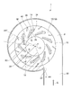
- FIG. 2 is a schematic cross-sectional view orthogonal to the rotation axis O of the turbine 1 shown in FIG. 2 is a view of the turbine 1 in the direction of the arrow B shown in FIG. 1, and for simplification of the description, a cross section of a portion of the housing 6 including the scroll passage 8, the nozzle plate 12, and The nozzle vanes 14 are shown, and illustration of the turbine impeller 4 and the like is omitted.
- a plurality of nozzle vanes 14 for adjusting the flow of exhaust gas flowing into the turbine impeller 4 are arranged in the circumferential direction.
- the intermediate flow passage 10 is provided with a nozzle mount 16 to which the nozzle vanes 14 are attached, and a nozzle plate 12 provided on the opposite side across the nozzle vanes 14 in the axial direction of the turbine 1 (hereinafter simply referred to as “axial direction”). Between the plate of the invention).
- the nozzle mount 16 is fixed to the bearing housing 6b by a bolt (not shown) or the like.
- a columnar member (not shown) or the like extending in the axial direction is provided between the nozzle mount 16 and the nozzle plate 12, and the nozzle plate 12 is axially separated from the nozzle mount 16 by the columnar member or the like. It is supported.
- An annular seal member 26 is provided between the nozzle plate 12 and the inner circumferential wall portion 22 of the housing 6, and the exhaust gas leaks from the scroll passage 8 to the space on the downstream side of the turbine impeller 4 (ie, the turbine impeller Leakage of the exhaust gas not through 4 is suppressed.
- the nozzle vanes 14 include an airfoil having a leading edge 34 and a trailing edge 36 (see FIG. 2) extending between the nozzle mount 16 and the nozzle plate 12.
- the nozzle vanes 14 also include pressure surfaces 38 and suction surfaces 40 that extend from the leading edge 34 to the trailing edge 36. In the cross section perpendicular to the axial direction (see FIG. 1), the suction surface 40 is located radially outward of the pressure surface 38.
- Each of the plurality of nozzle vanes 14 is connected to one end side of the lever plate 18 via the nozzle shaft 20. Further, the other end side of the lever plate 18 is connected to a disk-like drive ring 19.
- the drive ring 19 is driven by an actuator (not shown) to be rotatable about the rotation axis O.
- each lever plate 18 rotates, and accordingly, the nozzle shaft 20 rotates about the rotation axis Q along the axial direction, and the nozzle vanes 14 through the nozzle shaft 20.
- the opening degree (wing angle) of is changed.
- the exhaust gas (see arrow G in FIGS. 1 and 2) that flows from the inlet passage 30 (see FIG. 2) and flows through the scroll passage 8 is a nozzle mount It flows into the intermediate flow passage 10 between the nozzle 16 and the nozzle plate 12, and the flow direction is controlled by the nozzle vanes 14 to flow to the center of the housing 6. Then, after acting on the turbine impeller 4, the gas is discharged from the exhaust outlet 7 to the outside. Further, by changing the opening degree of the nozzle vanes 14 appropriately in accordance with the flow rate of the exhaust gas flowing into the turbine 1, the exhaust gas passage area in the housing 6 is changed to adjust the flow velocity of the exhaust gas to the turbine impeller 4; Good turbine efficiency can be obtained.
- the nozzle plate 12 (plate) has an opening 24 in the axial direction with respect to the inner peripheral wall 22 of the housing 6 to the intermediate flow passage 10 side and the intermediate flow passage 10. It is provided facing.
- the nozzle plate 12 is formed with at least one through hole 28 communicating the intermediate flow passage 10 with the gap 24.
- the through hole 28 is also referred to as at least one of the plurality of nozzle vanes 14 (hereinafter referred to as “the nozzle vane 14 corresponding to the through hole 28” or the like on the surface 13 of the nozzle plate 12 facing the intermediate flow passage 10. Open radially outward with respect to the suction surface 40 of the.
- one through hole 28 is provided corresponding to each of the plurality of nozzle vanes 14 (that is, the number of through holes 28 is the same as the number of nozzle vanes 14).
- the nozzle plate 12 may have one through hole 28 corresponding to a part of the plurality of nozzle vanes 14 (i.e., the number of the through holes 28). May be less than the nozzle vanes 14).
- FIG. 6 is a cross-sectional view along the axial direction of a typical turbine 1 '.
- the turbine 1 'shown in FIG. 6 basically has the same configuration as the turbine 1 shown in FIG. 1, but with the turbine 1 shown in FIG. 1 in that the above-mentioned through holes 28 are not provided in the nozzle plate 12. It is different.
- the gap 24 between the inner circumferential wall 22 of the housing 6 and the nozzle plate 12 forming the intermediate flow passage 10 has a relatively high pressure (region P H in FIG. 6), the suction surface 40 near the nozzle vanes 14 provided in the intermediate flow path 10, there are cases where relatively low pressure region P L is formed (see FIG. 6).
- relatively low pressure region P L is formed (see FIG. 6).
- the flow S with a disturbance toward the suction surface of the nozzle vane via the outer peripheral end of the nozzle plate 12 from the gap 24 described above 6) may occur. Flow with such disturbances can cause pressure losses.
- the intermediate flow passage 10 and the gap 24 are communicated with each other, and at the intermediate flow passage 10 side, the penetration is opened at a position radially outward with respect to the suction surface 40 of the nozzle vane 14 Since the holes 28 are provided in the plate, the vicinity of the negative pressure surface 40 of the nozzle vanes 14 of the intermediate flow passage 10 and the gap 24 are equalized through the through holes 28. Therefore, due to the pressure difference between the vicinity of the suction surface 40 of the nozzle vane 14 and the gap 24, a flow from the clearance 24 toward the suction surface 40 of the nozzle vane 14 via the outer peripheral end of the nozzle plate 12 (FIG. 6) Since the reference is suppressed, the pressure loss in the turbine 1 can be reduced.
- FIG. 3 is a partial enlarged view of FIG. 2 and shows a pair of circumferentially adjacent nozzle vanes 14 and the periphery thereof.
- 4 is a cross-sectional view along the axial direction of the turbine 1 shown in FIG. 3, that is, a partially enlarged view of FIG.
- FIG. 5 is a diagram showing the pair of nozzle vanes 14 and the periphery thereof corresponding to FIG. 3, and a diagram showing the case where the opening degree of the nozzle vanes 14 is maximum.
- the opening degree of the nozzle vanes 14 corresponds to the angle A formed by the cord directions of the pair of nozzle vanes 14 adjacent in the circumferential direction (the direction connecting the front edge 34 and the rear edge 36), and the larger the angle A
- the opening degree of the nozzle vanes 14 is large.
- FIG. 5 shows a pair of circumferentially adjacent nozzle vanes 14 when the opening degree of the nozzle vanes 14 is maximum, and at this time, the angle A between the cord directions of the pair of nozzle vanes is A1.
- the straight line Lc in FIGS. 3 and 5 is a straight line in the cord direction of the nozzle vanes 14.
- the through holes 28 may be formed, for example, as shown in FIG. It opens at a position radially outward with respect to the negative pressure surface 40 of the nozzle vane 14 on the surface 13 opposed to the intermediate flow passage 10. That is, for example, as shown in FIGS. 3 to 4 and 5, at least a part of the opening 28 a on the surface 13 of the through hole 28 is located radially outward of the suction surface 40 of the nozzle vane 14.
- the pressure difference between the gap 24 and the vicinity of the suction surface 40 of the nozzle vane 14 that can occur during operation of the turbine is large when the opening degree of the nozzle vane 14 is relatively large. It has been found that the pressure loss due to the pressure difference is remarkable.
- the through holes 28 are formed on the surface 13 of the nozzle plate 12 in at least a part of the wide opening range of the nozzle vane 14 in which the above-mentioned angle A is 0.5 ⁇ A 1 or more.
- the gap 24 can be reliably equalized. Therefore, the pressure loss in the turbine 1 is suppressed by suppressing the flow S (see FIG. 6) from the gap 24 caused by the pressure difference described above to the negative pressure surface 40 of the nozzle vane 14 via the outer peripheral end of the nozzle plate 12. Can be reduced more effectively.
- the through holes 28 extend circumferentially of the plane 13 of the nozzle plate 12 relative to the pivot axis Q of the nozzle vanes 14 corresponding to the through holes 28.
- the opening 28a on the surface 13 of the through hole 28 is positioned on the upstream side of the exhaust gas flow in the circumferential direction than the radial straight line L R (see FIGS. 3 and 5) passing through the pivot axis Q of the nozzle vane 14 .
- the above-mentioned through holes 28 open on the surface 13 of the nozzle plate 12 facing the intermediate flow passage 10 at a position upstream of the rotational axis Q of the nozzle vanes 14 in the exhaust gas flow direction in the circumferential direction.
- the opening degree of the nozzle vane 14 is increased, the opening 28 a on the surface 13 of the through hole 28 easily approaches the negative pressure surface 40 of the nozzle vane 14. Therefore, the pressure loss in the turbine 1 can be reduced by suppressing the flow (see FIG. 6) from the gap 24 caused by the pressure difference described above to the negative pressure surface 40 of the nozzle vane 14 via the outer peripheral end of the nozzle plate 12. It can be reduced more effectively.
- the distance between the through hole 28 and the suction surface 40 of the nozzle vane 14 corresponding to the through hole 28 is The radial distance L (see FIGS. 3 and 4) is equal to or less than the diameter D of the through hole 28 (see FIG. 3).
- the opening degree of the nozzle vane 14 angle A described above is 0.75 ⁇ A 1
- large opening area of the nozzle vane 14 (for example, the opening area angle a described above is 0.5 ⁇ a 1 or more) in a through-hole 28, the suction surface 40 of the nozzle vane 14 Are relatively close. Therefore, in the large opening area of the nozzle vane 14, a region near the negative pressure surface 40 of the nozzle vane 14 in the intermediate flow passage 10 can be communicated with the gap 24 through the through hole 28.
- pressure equalization can be performed more smoothly in the vicinity of the negative pressure surface 40 of the nozzle vane 14 of the intermediate flow passage 10 and the gap 24. Therefore, due to the pressure difference between the vicinity of the suction surface 40 of the nozzle vane 14 and the gap 24, the flow S from the clearance 24 toward the suction surface 40 of the nozzle vane 14 via the outer peripheral end of the nozzle plate 12 (see FIG. 6) can be suppressed more effectively.
- At least a portion of the through holes 28 in the surface 13 of the nozzle plate 12 may extend to the through holes 28 when the opening of each of the plurality of nozzle vanes 14 is at a maximum (see FIG. 5). It is offset radially outward from the corresponding nozzle vanes 14. That is, the opening 28 a on the surface 13 of the through hole 28 is at least partially located radially outward of the suction surface 40 of the nozzle vane 14.
- the opening degree of the nozzle vanes 14 is maximum (i.e., when the angle A described above is A 1), at least a part of the through-hole 28 is opposed to the intermediate flow path 10 of the nozzle plate 12 In the surface 13, it is offset radially outward from the nozzle vanes 14. That is, even when the opening degree of the nozzle vane 14 is maximized and the negative pressure surface 40 of the nozzle vane 14 comes closest to the through hole 28, the opening 28 a in the surface 13 of the nozzle plate 12 of the through hole 28 is the nozzle vane 14.
- the through holes 28 extend along the extension direction of the suction surface 40 of the nozzle vane 14 corresponding to the through holes 28. .
- the suction surface 40 of the nozzle vane 14 in a cross section including the axial direction, extends at an angle to the axial direction, and the through holes 28 , Extending in the direction of inclination relative to the axial direction of the suction surface 40.
- the negative pressure surface 40 of the nozzle vane 14 is radially inward from the nozzle plate 12 (shroud side) toward the nozzle mount 16 (hub side). It is inclined to approach.
- the angle ⁇ 1 (see FIG. 4) with respect to the axial direction of the suction surface 40 of the nozzle vane 14 in a cross section including the axial direction and the angle ⁇ 2 (see FIG. 4) with respect to the axial direction It may satisfy ⁇ 1 ⁇ 2
- the through hole 28 is formed to extend along the extension direction of the suction surface 40 of the nozzle vane 14. Therefore, it is possible to reduce the disturbance of the flow from the through hole 28 into the intermediate flow passage 10, and to reduce the pressure loss in the turbine more effectively.
- the angle at the position of the scroll tongue 32 is 0 degree (see FIG. 2) around the rotation axis O of the turbine 1, and the exhaust gas flow direction in the circumferential direction Is a positive angular direction, at least one through hole 28 is located within the range of 220 degrees or more and 360 degrees or less.
- range R1 shown with the oblique line in FIG. 2 shows the said angle range (range of 220 to 360 degree), and angle (phi) shows an example of the angle within the said range.
- the scroll tongue portion 32 is a connection portion between the winding start and the winding end of the scroll portion forming the scroll passage 8 in the housing 6.
- the pressure difference between the vicinity of the negative pressure surface 40 of the nozzle vane 14 and the gap 24 tends to be particularly large near the outlet of the scroll passage 8 (near the winding end of the scroll).
- the flow S (see FIG. 6) is likely to occur with turbulence that can cause pressure loss in the.
- at least one through hole 28 is provided in the range R1 in which the above-described angle in the circumferential direction is 220 degrees or more and 360 degrees or less (that is, near the exit of the scroll passage 8).
- the gap 24 and the vicinity of the negative pressure surface 40 of the nozzle vane 14 of the intermediate flow passage 10 are equalized through the through hole 28.
- a representation representing a relative or absolute arrangement such as “in a direction”, “along a direction”, “parallel”, “orthogonal”, “center”, “concentric” or “coaxial”
- a representation representing a relative or absolute arrangement such as “in a direction”, “along a direction”, “parallel”, “orthogonal”, “center”, “concentric” or “coaxial”
- expressions that indicate that things such as “identical”, “equal” and “homogeneous” are equal states not only represent strictly equal states, but also have tolerances or differences with which the same function can be obtained. It also represents the existing state.
- expressions representing shapes such as a square shape and a cylindrical shape not only indicate shapes such as a square shape and a cylindrical shape in a geometrically strict sense, but also within the range where the same effect can be obtained. Also, the shape including the uneven portion, the chamfered portion and the like shall be indicated. Moreover, in the present specification, the expressions “comprising”, “including” or “having” one component are not exclusive expressions excluding the presence of other components.
Abstract
This turbine is provided with: a turbine impeller; a housing that is provided so as to cover the turbine impeller and that includes a scroll flow passage located on the outer circumferential side of the turbine impeller and includes an inner circumferential wall portion defining the inner circumferential side boundary of the scroll flow passage; a plurality of nozzle vanes provided in an intermediate flow passage located, in an exhaust gas flow direction, downstream from the scroll flow passage and upstream from the turbine impeller; and a plate provided on the intermediate flow passage side so as to have a gap, in the axial direction, relative to the inner circumferential wall portion and to face the intermediate flow passage. The plate has at least one through hole connecting the intermediate flow passage to the gap. The at least one through hole is open, in a surface of the plate opposed to the intermediate flow passage, at a position radially outside a negative pressure surface of at least one of the plurality of nozzle vanes.
Description
本開示は、タービン及びターボチャージャに関する。
The present disclosure relates to a turbine and a turbocharger.
タービン動翼に流入する排ガス流れを調整するノズルベーンを備えたターボチャージャが用いられている。
Turbochargers with nozzle vanes are used to regulate the exhaust gas flow entering the turbine blades.
例えば、特許文献1には、タービンインペラの外周側に設けられる流れ空間(スクロール流路)からタービンインペラへ流入する排ガスが通る流れ空間(中間流路)にガイドベーン(ノズルベーン)が設けられたターボチャージャが開示されている。上述の中間流路は、ガイドベーンを支持する翼支持リングと、該翼支持リングに向き合うように配置されるカバーディスクとの間に形成されている。ガイドベーンは、翼支持リングを貫通する翼支持ピンを介して翼支持リングに回転可能に取り付けられている。また、翼支持リングとともに中間流路を形成するカバーディスクには、翼支持ピンの延長線上に、該翼支持ピンと同じ方向に延びる貫通孔が設けられている。これにより、カバーディスクの両側の圧力差(すなわち、スクロール流路と中間流路の圧力差)に起因する力を、ガイドベーンを介して翼支持ピンに対して与えることで、翼支持ピンに作用する力を相殺し、ガイドベーン等の摩耗を抑制するようになっている。
For example, Patent Document 1 discloses a turbo in which guide vanes (nozzle vanes) are provided in a flow space (intermediate flow path) through which exhaust gas flowing into the turbine impeller from the flow space (scroll flow path) provided on the outer peripheral side of the turbine impeller passes. A charger is disclosed. The above-mentioned intermediate flow path is formed between the wing support ring supporting the guide vanes and the cover disc arranged to face the wing support ring. The guide vanes are rotatably mounted to the wing support ring via a wing support pin passing through the wing support ring. Further, the cover disk that forms an intermediate flow path with the wing support ring is provided with a through hole extending in the same direction as the wing support pin on the extension of the wing support pin. Thereby, the force due to the pressure difference on both sides of the cover disk (that is, the pressure difference between the scroll flow passage and the middle flow passage) is applied to the blade support pins via the guide vanes to act on the blade support pins. It is designed to offset the force of the guide vanes and to suppress the wear of the guide vanes and the like.
ところで、本発明者らの鋭意検討の結果、ノズルベーンを備えたターボチャージャの運転中に、ハウジング内部で圧力分布が生じ、特に、スクロール流路を形成するハウジングの壁面と、ノズルベーンが設けられる中間流路を形成するプレートとの間に形成される隙間の圧力が比較的大きくなるのに対し、ノズルベーンの負圧面近傍の圧力が低くなることがわかった。上述の隙間とノズルベーンの負圧面近傍との間の圧力差は、タービンにおける圧力損失の原因となり得るため、この圧力差を低減することが望まれる。
By the way, as a result of intensive studies by the present inventors, pressure distribution occurs inside the housing during operation of the turbocharger provided with the nozzle vanes, and in particular, the wall surface of the housing forming the scroll flow passage and the intermediate flow provided with the nozzle vanes. It has been found that the pressure in the vicinity of the suction surface of the nozzle vane is low while the pressure in the gap formed between the plate forming the passage is relatively high. Since the pressure difference between the above-mentioned gap and the vicinity of the suction surface of the nozzle vane can cause a pressure loss in the turbine, it is desirable to reduce this pressure difference.
上述の事情に鑑みて、本発明の少なくとも一実施形態は、ハウジング内部の圧力分布に起因する圧力損失を低減可能なタービン及びターボチャージャを提供することを目的とする。
In view of the above-described circumstances, at least one embodiment of the present invention aims to provide a turbine and a turbocharger capable of reducing pressure loss due to pressure distribution inside a housing.
(1)本発明の少なくとも一実施形態に係るタービンは、
タービンインペラと、
前記タービンインペラを覆うように設けられ、前記タービンインペラの外周側に位置するスクロール流路及び前記スクロール流路の内周側境界を画定する内周壁部を含むハウジングと、
排ガス流れ方向において前記スクロール流路の下流側且つ前記タービンインペラの上流側に位置する中間流路に設けられる複数のノズルベーンと、
前記内周壁部に対して軸方向に隙間を空けて前記中間流路側に、前記中間流路に面して設けられるプレートと、
を備え、
前記プレートは、前記中間流路と前記隙間とを連通させる少なくとも1つの貫通孔を有し、
前記少なくとも1つの貫通孔は、前記プレートのうち前記中間流路に対向する面上において、前記複数のノズルベーンのうち少なくとも1つの負圧面に対して径方向外側の位置に開口する。 (1) A turbine according to at least one embodiment of the present invention,
A turbine impeller,
A housing including a scroll passage provided on the outer circumferential side of the turbine impeller and an inner circumferential wall defining an inner circumferential boundary of the scroll passage, the housing being provided to cover the turbine impeller;
A plurality of nozzle vanes provided in an intermediate flow passage located downstream of the scroll flow passage and upstream of the turbine impeller in an exhaust gas flow direction;
A plate provided facing the intermediate flow passage on the intermediate flow passage side with a gap in the axial direction with respect to the inner peripheral wall portion;
Equipped with
The plate has at least one through hole communicating the intermediate flow passage with the gap.
The at least one through hole opens at a position radially outward with respect to at least one suction surface of the plurality of nozzle vanes on the surface of the plate facing the intermediate flow passage.
タービンの運転中、ハウジングの内周壁部と、中間流路を形成するプレートとの間の隙間は比較的高圧となる一方、中間流路に設けられたノズルベーンの負圧面近傍には、比較的低圧の領域が形成される場合がある。この場合、ノズルベーン負圧面近傍と上述の隙間との圧力差に起因して、上述の隙間からプレートの外周端を経由してノズルベーンの負圧面へ向かう乱れを伴う流れが生じることがある。このような乱れを伴う流れは圧力損失の原因となり得る。
この点、上記(1)の構成によれば、上述の中間流路と隙間とを連通させるとともに、中間流路側においてノズルベーンの負圧面に対して径方向外側の位置に開口する貫通孔をプレートに設けたので、該貫通孔を介して、中間流路のノズルベーンの負圧面近傍と、隙間とが均圧化される。よって、ノズルベーンの負圧面近傍と隙間との間の圧力差に起因する、隙間からプレートの外周端を経由してノズルベーンの負圧面へ向かう乱れを伴う流れが抑制されるので、タービンにおける圧力損失を低減することができる。
また、ノズルベーンの負圧面近傍と隙間との間に上述の圧力差がある場合、この圧力差に起因してノズルベーンがプレートに向かって傾斜し、ノズルベーンとプレートとの間で摩擦が生じることがある。この点、上記(1)の構成によれば、上述の貫通孔を介して中間流路と隙間とが均圧化されるので、上述の圧力差に起因するノズルベーンの傾斜を抑制することができ、ノズルベーンとプレートとの間の摩耗を抑制することができる。 During operation of the turbine, the gap between the inner circumferential wall of the housing and the plate forming the intermediate flow passage is at a relatively high pressure, while at a relatively low pressure near the suction surface of the nozzle vane provided in the intermediate flow passage The region of may be formed. In this case, due to the pressure difference between the vicinity of the nozzle vane suction surface and the above-mentioned gap, a flow may be generated from the above-mentioned gap to the suction surface of the nozzle vane via the outer peripheral end of the plate. Flow with such disturbances can cause pressure losses.
In this point, according to the configuration of the above (1), while connecting the above-mentioned intermediate flow passage and the gap, the plate is provided with the through hole opened at the radially outer position with respect to the suction surface of the nozzle vane on the intermediate flow passage side Since it is provided, the gap and the vicinity of the negative pressure surface of the nozzle vane of the intermediate flow passage are equalized through the through hole. Therefore, the pressure loss in the turbine is suppressed because the flow from the clearance toward the suction surface of the nozzle vane via the outer peripheral end of the plate due to the pressure difference between the vicinity of the suction surface of the nozzle vane and the clearance is suppressed. It can be reduced.
In addition, if there is the above-mentioned pressure difference between the vicinity of the suction surface of the nozzle vane and the clearance, the pressure difference may cause the nozzle vane to incline toward the plate and cause friction between the nozzle vane and the plate . In this respect, according to the configuration of the above (1), since the intermediate flow passage and the gap are equalized through the above-mentioned through hole, the inclination of the nozzle vane due to the above-mentioned pressure difference can be suppressed. The wear between the nozzle vanes and the plate can be suppressed.
(2)幾つかの実施形態では、上記(1)の構成において、
前記複数のノズルベーンは、前記中間流路内において周方向に配列されるとともに、前記軸方向に沿って延びる回動軸の周りを回動可能に設けられ、
前記周方向に隣接する一対のノズルベーンの各々のコード方向がなす角度をAとし、前記複数のノズルベーンの各々の開度が最大であるときの前記角度をA1としたとき、
前記角度Aが0.5×A1以上となるノズルベーンの大開度域の少なくとも一部において、前記少なくとも1つの貫通孔は、前記面上において、前記負圧面に対して径方向外側の位置に開口する。 (2) In some embodiments, in the configuration of (1) above,
The plurality of nozzle vanes are circumferentially arranged in the intermediate flow passage, and provided rotatably around a rotation axis extending along the axial direction.
Assuming that the angle formed by the cord directions of the pair of nozzle vanes adjacent in the circumferential direction is A, and the angle when the opening degree of each of the plurality of nozzle vanes is maximum is A 1
In at least a part of the large opening degree area of the nozzle vane where the angle A is 0.5 × A 1 or more, the at least one through hole opens at a position radially outward with respect to the suction surface on the surface. Do.
本発明者らの知見によれば、タービン運転中に生じ得るノズルベーン負圧面近傍と隙間との圧力差は、ノズルベーンの開度が比較的大きいときに大きくなり、該圧力差に起因する圧力損失が顕著になることが分かった。
この点、上記(2)の構成では、上述の角度Aが0.5×A1以上となるノズルベーンの大開度域の少なくとも一部において、貫通孔は、プレートのうち中間流路に対向する面上において、ノズルベーンの負圧面に対して径方向外側の位置に開口するようにしたので、ノズルベーンの大開度域において、該貫通孔を介して、中間流路のノズルベーンの負圧面近傍と、隙間とを確実に均圧化させることができる。よって、上述の圧力差に起因する隙間からプレートの外周端を経由してノズルベーンの負圧面へ向かう乱れを伴う流れを抑制して、タービンにおける圧力損失をより効果的に低減することができる。 According to the findings of the present inventors, the pressure difference between the nozzle vane suction surface and the gap, which may occur during turbine operation, increases when the opening degree of the nozzle vane is relatively large, and the pressure loss due to the pressure difference It turned out that it becomes remarkable.
In this respect, in the configuration of the above (2), in at least a part of the large opening area of the nozzle vane where the above-mentioned angle A is 0.5 × A 1 or more, the through hole faces the middle flow path in the plate In the above, since the nozzle vane is opened at a position radially outward with respect to the suction surface of the nozzle vane, the vicinity of the suction surface of the nozzle vane of the intermediate flow passage and the clearance Can be reliably equalized. Therefore, it is possible to more effectively reduce the pressure loss in the turbine by suppressing the flow accompanied by the disturbance from the gap due to the pressure difference to the suction surface of the nozzle vane via the outer peripheral end of the plate.
(3)幾つかの実施形態では、上記(1)又は(2)の構成において、
前記複数のノズルベーンは、前記軸方向に沿った回動軸の周りを回動可能に設けられ、
前記少なくとも1つの貫通孔は、前記プレートの前記面上において、前記少なくとも1つのノズルベーンの前記回動軸よりも周方向において前記排ガス流れ方向の上流側の位置に開口する。 (3) In some embodiments, in the configuration of (1) or (2) above,
The plurality of nozzle vanes are provided so as to be pivotable about a pivot axis along the axial direction,
The at least one through hole opens at a position on the upstream side of the exhaust gas flow direction in the circumferential direction with respect to the pivot axis of the at least one nozzle vane on the surface of the plate.
上記(3)の構成によれば、上述の貫通孔は、プレートのうち中間流路に対向する面上において、ノズルベーンの回動軸よりも周方向において排ガス流れ方向の上流側の位置に開口するようにしたので、ノズルベーンの開度が大きくなるときに、貫通孔の上述の面上での開口がノズルベーンの負圧面に近づきやすい。よって、上述の圧力差に起因する隙間からプレートの外周端を経由してノズルベーンの負圧面へ向かう乱れを伴う流れを抑制して、タービンにおける圧力損失をより効果的に低減することができる。
According to the configuration of the above (3), the above-mentioned through hole opens at a position on the upstream side in the exhaust gas flow direction in the circumferential direction with respect to the rotation axis of the nozzle vane on the surface facing the intermediate flow passage in the plate. As a result, when the opening degree of the nozzle vane increases, the opening on the above-described surface of the through hole tends to approach the suction surface of the nozzle vane. Therefore, it is possible to more effectively reduce the pressure loss in the turbine by suppressing the flow accompanied by the disturbance from the gap due to the pressure difference to the suction surface of the nozzle vane via the outer peripheral end of the plate.
(4)幾つかの実施形態では、上記(1)乃至(3)の何れかの構成において、
前記複数のノズルベーンは、前記中間流路内において周方向に配列されるとともに、前記軸方向に沿った回動軸の周りを回動可能に設けられ、
前記周方向に隣接する一対のノズルベーンの各々のコード方向がなす角度をAとし、前記複数のノズルベーンの開度が最大であるときの前記角度をA1としたとき、
前記角度Aが0.75×A1となる前記複数のノズルベーンの開度において、前記少なくとも1つの貫通孔と前記少なくとも1つのノズルベーンの前記負圧面との間の径方向における距離Lが前記少なくとも1つの貫通孔の直径D以下である。 (4) In some embodiments, in any of the configurations of (1) to (3) above,
The plurality of nozzle vanes are circumferentially arranged in the intermediate flow passage, and are provided so as to be rotatable around a rotation axis along the axial direction.
Assuming that the angle formed by the cord directions of the pair of nozzle vanes adjacent in the circumferential direction is A, and the angle when the opening degree of the plurality of nozzle vanes is maximum is A 1 .
In opening of the plurality of nozzle vanes the angle A becomes 0.75 × A 1, the distance L is at least 1 in the radial direction between the suction side of the said at least one through-hole at least one nozzle vane Or less than the diameter D of one through hole.
上記(4)の構成によれば、上述の角度Aが0.75×A1となるノズルベーンの開度において、貫通孔とノズルベーンの負圧面との間の径方向における距離Lが該貫通孔の直径D以下となるように設定したので、ノズルベーンの大開度域(例えば、上述の角度Aが0.5×A1以上である開度域)において、貫通孔と、ノズルベーンの負圧面とが比較的近くに位置することとなる。よって、ノズルベーンの大開度域において、中間流路のうちノズルベーン負圧面近傍の領域と、上述の隙間とを、貫通孔を介して連通させることができ、該貫通孔を介して、中間流路のノズルベーンの負圧面近傍と隙間とをより円滑に均圧化させることができる。よって、ノズルベーンの負圧面近傍と隙間との間の圧力差に起因する、隙間からプレートの外周端を経由してノズルベーンの負圧面へ向かう乱れを伴う流れをより効果的に抑制することができる。
According to the configuration of the above (4), at the opening degree of the nozzle vane where the above-mentioned angle A is 0.75 × A 1 , the distance L in the radial direction between the through hole and the negative pressure surface of the nozzle vane is Since the diameter is set to be equal to or less than the diameter D, the through hole and the suction surface of the nozzle vane are compared in the large opening degree region of the nozzle vane (for example, the opening degree region where the above-mentioned angle A is 0.5 × A 1 or more). It will be located near the target. Therefore, in the large opening area of the nozzle vanes, the region in the vicinity of the nozzle vane negative pressure surface in the intermediate flow passage can be communicated with the above-mentioned gap through the through hole, and the intermediate flow passage It is possible to equalize the gap and the vicinity of the suction surface of the nozzle vane more smoothly. Therefore, it is possible to more effectively suppress the flow accompanied by the disturbance from the clearance toward the suction surface of the nozzle vane via the outer peripheral end of the plate due to the pressure difference between the vicinity of the suction surface of the nozzle vane and the clearance.
(5)幾つかの実施形態では、上記(1)乃至(4)の何れかの構成において、
前記複数のノズルベーンは、前記中間流路内において周方向に配列されるとともに、前記軸方向に沿った回動軸の周りを回動可能に設けられ、
前記複数のノズルベーンの各々の開度が最大であるときに、前記少なくとも1つの貫通孔の少なくとも一部は、前記プレートの前記面において、前記少なくとも1つのノズルベーンから前記径方向の外側にずれて位置する。 (5) In some embodiments, in any of the configurations of (1) to (4) above,
The plurality of nozzle vanes are circumferentially arranged in the intermediate flow passage, and are provided so as to be rotatable around a rotation axis along the axial direction.
When the opening degree of each of the plurality of nozzle vanes is at a maximum, at least a portion of the at least one through hole is offset from the at least one nozzle vane to the radially outer side in the surface of the plate Do.
上記(5)の構成によれば、ノズルベーンの開度が最大であるときに(即ち、上述の角度AがA1であるときに)、貫通孔の少なくとも一部は、プレートの中間流路に対向する面において、ノズルベーンから径方向の外側にずれて位置する。すなわち、ノズルベーンの開度が最大となり、ノズルベーンの負圧面が最も貫通孔に近づくときであっても、該貫通孔のプレートの上述の面における開口が、ノズルベーンによって閉じられない。
よって、ノズルベーンの開度が最大であるときであっても、中間流路のうちノズルベーンの負圧面近傍の領域と隙間とを、貫通孔を介して確実に連通させることができる。これにより、該貫通孔を介して、中間流路のノズルベーンの負圧面近傍と隙間とを均圧化させることができ、ノズルベーンの負圧面近傍と隙間との間の圧力差に起因する、隙間からノズルプレートの外周端を経由してノズルベーンの負圧面へ向かう乱れを伴う流れをより効果的に抑制することができる。 According to the configuration of the above (5), when the opening degree of the nozzle vane is maximum (that is, when the above-mentioned angle A is A 1 ), at least a part of the through holes is in the middle flow path of the plate In the opposite surface, it is offset radially outward from the nozzle vanes. That is, even when the opening degree of the nozzle vane is maximized and the negative pressure surface of the nozzle vane most approaches the through hole, the opening in the above surface of the plate of the through hole is not closed by the nozzle vane.
Therefore, even when the opening degree of the nozzle vane is maximum, the region near the negative pressure surface of the nozzle vane and the gap in the intermediate flow passage can be reliably communicated via the through hole. Thereby, it is possible to equalize the gap between the nozzle vane near the suction surface and the gap in the intermediate flow passage through the through hole, and from the gap resulting from the pressure difference between the gap near the suction surface of the nozzle vane and the gap It is possible to more effectively suppress the flow accompanied by the disturbance toward the suction surface of the nozzle vane via the outer peripheral end of the nozzle plate.
(6)幾つかの実施形態では、上記(1)乃至(5)の何れかの構成において、
前記軸方向に直交する断面において、前記タービンの回転軸を中心として、スクロール舌部の位置における角度を0度とし、周方向における前記排ガス流れの向きを正の角度方向としたとき、前記少なくとも1つの貫通孔は、220度以上360度以下の範囲内に位置する。 (6) In some embodiments, in any of the configurations (1) to (5),
In the cross section orthogonal to the axial direction, the angle at the position of the scroll tongue portion is 0 degrees around the rotation axis of the turbine, and the direction of the exhaust gas flow in the circumferential direction is a positive angle direction, One through hole is located in the range of 220 degrees or more and 360 degrees or less.
本発明者らの知見によれば、スクロール流路の出口付近において、ノズルベーン負圧面近傍と上述の隙間との圧力差が特に大きくなる傾向があり、タービンにおける圧力損失の要因となり得る乱れを伴う流れが生じやすい。
この点、上記(6)の構成によれば、周方向における上述の角度が220度以上360度以下の範囲内(即ちスクロール流路の出口付近)に、上述の貫通孔を設けたので、当該周方向領域において、該貫通孔を介して、中間流路のノズルベーンの負圧面近傍と隙間とが均圧化される。よって、ノズルベーンの負圧面近傍と隙間との間の圧力差に起因する、隙間からプレートの外周端を経由してノズルベーンの負圧面へ向かう乱れを伴う流れを効果的に抑制して、タービンにおける圧力損失を効果的に低減することができる。 According to the findings of the present inventors, in the vicinity of the outlet of the scroll passage, the pressure difference between the vicinity of the nozzle vane suction surface and the above-mentioned gap tends to be particularly large, and flows with turbulence that can cause pressure loss in the turbine. Is likely to occur.
In this respect, according to the configuration of the above (6), since the above-mentioned through hole is provided in the range where the above-mentioned angle in the circumferential direction is in the range of 220 degrees or more and 360 degrees or less In the circumferential region, the vicinity of the negative pressure surface of the nozzle vane of the intermediate flow passage and the gap are equalized through the through hole. Therefore, the pressure in the turbine is effectively suppressed by causing a flow from the gap to the suction surface of the nozzle vane via the outer peripheral end of the plate due to the pressure difference between the vicinity of the suction surface of the nozzle vane and the gap. The loss can be effectively reduced.
(7)幾つかの実施形態では、上記(1)乃至(6)の何れかの構成において、
前記軸方向を含む断面において、前記少なくとも1つの貫通孔は、前記少なくとも1つのノズルベーンの前記負圧面の延在方向に沿って延びている。 (7) In some embodiments, in any of the configurations of (1) to (6) above,
In the cross section including the axial direction, the at least one through hole extends in the extending direction of the suction surface of the at least one nozzle vane.
上記(7)の構成によれば、貫通孔を、ノズルベーンの負圧面の延在方向に沿って延びるように形成したので、貫通孔から中間流路に流入する流れの乱れを低減することができる。よって、タービンにおける圧力損失をより効果的に低減することができる。
According to the configuration of the above (7), since the through hole is formed to extend along the extension direction of the suction surface of the nozzle vane, it is possible to reduce the disturbance of the flow from the through hole into the intermediate flow passage . Thus, pressure loss in the turbine can be reduced more effectively.
(8)幾つかの実施形態では、上記(7)の構成において、
前記軸方向を含む断面において、前記負圧面は、前記軸方向に対して傾斜して延在し、前記少なくとも1つの貫通孔は、前記負圧面の前記軸方向に対する傾斜方向に沿って延びている。 (8) In some embodiments, in the configuration of (7) above,
In the cross section including the axial direction, the suction surface extends at an angle with respect to the axial direction, and the at least one through hole extends along the inclination direction of the suction surface with respect to the axial direction. .
上記(8)の構成によれば、ノズルベーンの負圧面が軸方向に対して傾斜している場合に、該負圧面の傾斜方向に沿うように貫通孔を傾斜させて形成したので、上記(7)で述べた効果を得ることができる。
According to the configuration of the above (8), when the suction surface of the nozzle vane is inclined with respect to the axial direction, the through hole is formed to be inclined along the inclination direction of the suction surface. The effects described in) can be obtained.
(9)本発明の少なくとも一実施形態に係るターボチャージャは、
上記(1)乃至(8)の何れかに記載のタービンと、
前記タービンによって駆動されるように構成された圧縮機と、を備える。 (9) A turbocharger according to at least one embodiment of the present invention is
The turbine according to any one of the above (1) to (8);
And a compressor configured to be driven by the turbine.
上記(1)乃至(8)の何れかに記載のタービンと、
前記タービンによって駆動されるように構成された圧縮機と、を備える。 (9) A turbocharger according to at least one embodiment of the present invention is
The turbine according to any one of the above (1) to (8);
And a compressor configured to be driven by the turbine.
上記(9)の構成によれば、上述の中間流路と隙間とを連通させるとともに、中間流路側においてノズルベーンの負圧面に対して径方向外側の位置に開口する貫通孔をプレートに設けたので、該貫通孔を介して、中間流路のノズルベーンの負圧面近傍と隙間とが均圧化される。よって、ノズルベーンの負圧面近傍と隙間との間の圧力差に起因する、隙間からプレートの外周端を経由してノズルベーンの負圧面へ向かう乱れを伴う流れが抑制されるので、タービンにおける圧力損失を低減することができる。
また、ノズルベーンの負圧面近傍と隙間との間に上述の圧力差がある場合、この圧力差に起因してノズルベーンがプレートに向かって傾斜し、ノズルベーンとプレートとの間で摩擦が生じることがある。この点、上記(9)の構成によれば、上述の貫通孔を介して中間流路と隙間とが均圧化されるので、上述の圧力差に起因するノズルベーンの傾斜を抑制することができ、ノズルベーンとプレートとの間の摩耗を抑制することができる。 According to the configuration of the above (9), the plate is provided with the through hole opened at the position radially outward with respect to the negative pressure surface of the nozzle vane on the intermediate flow passage side while communicating the above intermediate flow passage and the gap. The pressure in the vicinity of the negative pressure surface of the nozzle vane of the intermediate flow passage and the gap are equalized through the through hole. Therefore, the pressure loss in the turbine is suppressed because the flow from the clearance toward the suction surface of the nozzle vane via the outer peripheral end of the plate due to the pressure difference between the vicinity of the suction surface of the nozzle vane and the clearance is suppressed. It can be reduced.
In addition, if there is the above-mentioned pressure difference between the vicinity of the suction surface of the nozzle vane and the clearance, the pressure difference may cause the nozzle vane to incline toward the plate and cause friction between the nozzle vane and the plate . In this respect, according to the configuration of the above (9), since the intermediate flow passage and the gap are equalized through the above-mentioned through hole, the inclination of the nozzle vane due to the above-mentioned pressure difference can be suppressed. The wear between the nozzle vanes and the plate can be suppressed.
本発明の少なくとも一実施形態によれば、ハウジング内部の圧力分布に起因する圧力損失を低減可能なタービン及びターボチャージャが提供される。
According to at least one embodiment of the present invention, a turbine and a turbocharger are provided that can reduce pressure loss due to pressure distribution inside the housing.
以下、添付図面を参照して本発明の幾つかの実施形態について説明する。ただし、実施形態として記載されている又は図面に示されている構成部品の寸法、材質、形状、その相対的配置等は、本発明の範囲をこれに限定する趣旨ではなく、単なる説明例にすぎない。
Hereinafter, some embodiments of the present invention will be described with reference to the accompanying drawings. However, the dimensions, materials, shapes, relative arrangements, etc. of the components described as the embodiments or shown in the drawings are not intended to limit the scope of the present invention to this, but are merely illustrative. Absent.
まず、幾つかの実施形態に係るターボチャージャの全体構成について説明する。
図1は、一実施形態に係るターボチャージャの回転軸Oに沿った概略断面図である。図1に示すように、ターボチャージャ100は、不図示のエンジンからの排ガスにより回転駆動されるように構成されたタービンインペラ4を含むタービン1と、軸受3によって回転可能に支持される回転シャフト2を介してタービン1と接続されたコンプレッサ(不図示)と、を備える。コンプレッサは、タービンインペラ4の回転により同軸駆動されて、エンジンへの吸気を圧縮するように構成されている。 First, the overall configuration of a turbocharger according to some embodiments will be described.
FIG. 1 is a schematic cross-sectional view along a rotation axis O of a turbocharger according to one embodiment. As shown in FIG. 1, theturbocharger 100 includes a turbine 1 including a turbine impeller 4 configured to be rotationally driven by exhaust gas from an engine (not shown), and a rotating shaft 2 rotatably supported by a bearing 3. And a compressor (not shown) connected to the turbine 1. The compressor is coaxially driven by the rotation of the turbine impeller 4 and is configured to compress the intake air to the engine.
図1は、一実施形態に係るターボチャージャの回転軸Oに沿った概略断面図である。図1に示すように、ターボチャージャ100は、不図示のエンジンからの排ガスにより回転駆動されるように構成されたタービンインペラ4を含むタービン1と、軸受3によって回転可能に支持される回転シャフト2を介してタービン1と接続されたコンプレッサ(不図示)と、を備える。コンプレッサは、タービンインペラ4の回転により同軸駆動されて、エンジンへの吸気を圧縮するように構成されている。 First, the overall configuration of a turbocharger according to some embodiments will be described.
FIG. 1 is a schematic cross-sectional view along a rotation axis O of a turbocharger according to one embodiment. As shown in FIG. 1, the
なお、図1に示すタービン1は、作動流体である排ガスが半径方向に流入するラジアルタービンであるが、タービン1の作動方式はこれに限定されない。例えば、幾つかの実施形態では、タービン1は、流入する作動流体が半径方向及び軸方向の速度成分を有する斜流タービンであってもよい。
In addition, although the turbine 1 shown in FIG. 1 is a radial turbine into which the exhaust gas which is a working fluid flows in radial direction, the operation system of the turbine 1 is not limited to this. For example, in some embodiments, the turbine 1 may be a mixed flow turbine where the incoming working fluid has radial and axial velocity components.
タービンインペラ4は、該タービンインペラ4を覆うように設けられたハウジング6に収容されており、回転シャフト2に連結されるハブ17と、ハブ17の外周面に周方向に配列される複数の動翼5とを含む。
ハウジング6は、タービンインペラ4の外周側に位置するスクロール流路8と、スクロール流路8の内周側境界9を画定する内周壁部22と、を含む。なお、図1に示すように、ハウジング6は、タービンインペラ4を収容する部分であるタービンハウジング6aと、軸受3を収容する部分である軸受ハウジング6bと、を含んでいてもよい。 Theturbine impeller 4 is accommodated in a housing 6 provided so as to cover the turbine impeller 4, and a hub 17 connected to the rotating shaft 2 and a plurality of motions circumferentially arranged on the outer peripheral surface of the hub 17 And wings 5 are included.
Thehousing 6 includes a scroll flow passage 8 positioned on the outer peripheral side of the turbine impeller 4 and an inner circumferential wall portion 22 defining an inner circumferential boundary 9 of the scroll flow passage 8. Note that, as shown in FIG. 1, the housing 6 may include a turbine housing 6 a that is a portion that accommodates the turbine impeller 4 and a bearing housing 6 b that is a portion that accommodates the bearing 3.
ハウジング6は、タービンインペラ4の外周側に位置するスクロール流路8と、スクロール流路8の内周側境界9を画定する内周壁部22と、を含む。なお、図1に示すように、ハウジング6は、タービンインペラ4を収容する部分であるタービンハウジング6aと、軸受3を収容する部分である軸受ハウジング6bと、を含んでいてもよい。 The
The
タービンインペラ4の外周側には、スクロール流路8からタービンインペラ4へと流入する排ガス流れが通過する中間流路10が形成されている。すなわち、中間流路10は、排ガス流れ方向において、スクロール流路8の下流側かつタービンインペラ4の上流側に位置している。
On the outer peripheral side of the turbine impeller 4 is formed an intermediate flow passage 10 through which the exhaust gas flow flowing from the scroll flow passage 8 to the turbine impeller 4 passes. That is, the intermediate flow passage 10 is located downstream of the scroll flow passage 8 and upstream of the turbine impeller 4 in the exhaust gas flow direction.
図2は、図1に示すタービン1の回転軸Oに直交する概略断面図である。なお、図2は、図1に示す矢印Bの方向にタービン1を視た図であり、説明の簡略化のため、ハウジング6のうちスクロール流路8を含む部分の断面、ノズルプレート12、及び、ノズルベーン14が示されており、タービンインペラ4等の図示を省略している。
FIG. 2 is a schematic cross-sectional view orthogonal to the rotation axis O of the turbine 1 shown in FIG. 2 is a view of the turbine 1 in the direction of the arrow B shown in FIG. 1, and for simplification of the description, a cross section of a portion of the housing 6 including the scroll passage 8, the nozzle plate 12, and The nozzle vanes 14 are shown, and illustration of the turbine impeller 4 and the like is omitted.
図1及び図2に示すように、中間流路10には、タービンインペラ4に流入する排ガス流れを調節するための複数のノズルベーン14が周方向に配列されている。
As shown in FIGS. 1 and 2, in the intermediate flow passage 10, a plurality of nozzle vanes 14 for adjusting the flow of exhaust gas flowing into the turbine impeller 4 are arranged in the circumferential direction.
中間流路10は、ノズルベーン14が取り付けられるノズルマウント16と、タービン1の軸方向(以下、単に「軸方向」ともいう。)においてノズルベーン14を挟んで反対側に設けられたノズルプレート12(本発明のプレート)との間に形成される。ノズルマウント16は、ボルト(不図示)等によって軸受ハウジング6bに固定されている。ノズルマウント16とノズルプレート12との間には、例えば軸方向に延びる柱状部材(不図示)等が設けられており、該柱状部材等によって、ノズルプレート12がノズルマウント16から軸方向に離間して支持されている。ノズルプレート12とハウジング6の内周壁部22との間には、環状のシール部材26が設けられており、スクロール流路8からタービンインペラ4の下流側の空間への排ガスの漏れ(即ちタービンインペラ4を介さない排ガスの漏れ)が抑制されるようになっている。
The intermediate flow passage 10 is provided with a nozzle mount 16 to which the nozzle vanes 14 are attached, and a nozzle plate 12 provided on the opposite side across the nozzle vanes 14 in the axial direction of the turbine 1 (hereinafter simply referred to as “axial direction”). Between the plate of the invention). The nozzle mount 16 is fixed to the bearing housing 6b by a bolt (not shown) or the like. For example, a columnar member (not shown) or the like extending in the axial direction is provided between the nozzle mount 16 and the nozzle plate 12, and the nozzle plate 12 is axially separated from the nozzle mount 16 by the columnar member or the like. It is supported. An annular seal member 26 is provided between the nozzle plate 12 and the inner circumferential wall portion 22 of the housing 6, and the exhaust gas leaks from the scroll passage 8 to the space on the downstream side of the turbine impeller 4 (ie, the turbine impeller Leakage of the exhaust gas not through 4 is suppressed.
ノズルベーン14は、ノズルマウント16とノズルプレート12との間に延びる前縁34及び後縁36(図2参照)を有する翼型部を含む。また、ノズルベーン14は、前縁34から後縁36にかけて延在する圧力面38及び負圧面40を含む。軸方向に直交する断面(図1参照)において、負圧面40は、圧力面38よりも径方向外側に位置する。
The nozzle vanes 14 include an airfoil having a leading edge 34 and a trailing edge 36 (see FIG. 2) extending between the nozzle mount 16 and the nozzle plate 12. The nozzle vanes 14 also include pressure surfaces 38 and suction surfaces 40 that extend from the leading edge 34 to the trailing edge 36. In the cross section perpendicular to the axial direction (see FIG. 1), the suction surface 40 is located radially outward of the pressure surface 38.
複数のノズルベーン14の各々は、ノズルシャフト20を介してレバープレート18の一端側に連結されている。また、レバープレート18の他端側は、円盤状のドライブリング19に連結されている。
ドライブリング19は、アクチュエータ(不図示)により駆動されて回転軸Oを中心として回転可能になっている。ドライブリング19が回転すると、各レバープレート18が回転し、これに伴い、ノズルシャフト20が、軸方向に沿った回動軸Qを中心として回動して、該ノズルシャフト20を介してノズルベーン14の開度(翼角)が変化するように構成されている。 Each of the plurality ofnozzle vanes 14 is connected to one end side of the lever plate 18 via the nozzle shaft 20. Further, the other end side of the lever plate 18 is connected to a disk-like drive ring 19.
Thedrive ring 19 is driven by an actuator (not shown) to be rotatable about the rotation axis O. When the drive ring 19 rotates, each lever plate 18 rotates, and accordingly, the nozzle shaft 20 rotates about the rotation axis Q along the axial direction, and the nozzle vanes 14 through the nozzle shaft 20. The opening degree (wing angle) of is changed.
ドライブリング19は、アクチュエータ(不図示)により駆動されて回転軸Oを中心として回転可能になっている。ドライブリング19が回転すると、各レバープレート18が回転し、これに伴い、ノズルシャフト20が、軸方向に沿った回動軸Qを中心として回動して、該ノズルシャフト20を介してノズルベーン14の開度(翼角)が変化するように構成されている。 Each of the plurality of
The
このように構成されるターボチャージャ100のタービン1では、入口流路30(図2参照)から流入してスクロール流路8を流れた排ガス(図1及び図2の矢印G参照)は、ノズルマウント16とノズルプレート12との間の中間流路10に流れ込み、ノズルベーン14によって流れ方向が制御されて、ハウジング6の中心部へと流れる。そして、タービンインペラ4に作用した後に、排気出口7から外部に排出される。
また、ノズルベーン14の開度を、タービン1に流入する排ガス流量に応じて適切に変化させることにより、ハウジング6内の排ガス通路面積を変化させて、タービンインペラ4への排ガスの流速を調節し、良好なタービン効率を得ることができる。 In theturbine 1 of the turbocharger 100 configured as described above, the exhaust gas (see arrow G in FIGS. 1 and 2) that flows from the inlet passage 30 (see FIG. 2) and flows through the scroll passage 8 is a nozzle mount It flows into the intermediate flow passage 10 between the nozzle 16 and the nozzle plate 12, and the flow direction is controlled by the nozzle vanes 14 to flow to the center of the housing 6. Then, after acting on the turbine impeller 4, the gas is discharged from the exhaust outlet 7 to the outside.
Further, by changing the opening degree of thenozzle vanes 14 appropriately in accordance with the flow rate of the exhaust gas flowing into the turbine 1, the exhaust gas passage area in the housing 6 is changed to adjust the flow velocity of the exhaust gas to the turbine impeller 4; Good turbine efficiency can be obtained.
また、ノズルベーン14の開度を、タービン1に流入する排ガス流量に応じて適切に変化させることにより、ハウジング6内の排ガス通路面積を変化させて、タービンインペラ4への排ガスの流速を調節し、良好なタービン効率を得ることができる。 In the
Further, by changing the opening degree of the
以下、幾つかの実施形態に係るタービン1の特徴について説明する。
図1及び図2に示すように、ノズルプレート12(プレート)は、ハウジング6の内周壁部22に対して、軸方向に隙間24を空けて中間流路10側に、該中間流路10に面して設けられる。該ノズルプレート12には、中間流路10と隙間24とを連通させる少なくとも1つの貫通孔28が形成されている。そして、この貫通孔28は、ノズルプレート12のうち中間流路10に対向する面13上において、複数のノズルベーン14のうち少なくとも1つ(以下、「貫通孔28に対応するノズルベーン14」等ともいう。)の負圧面40に対して径方向外側の位置に開口する。 Hereinafter, features of theturbine 1 according to some embodiments will be described.
As shown in FIG. 1 and FIG. 2, the nozzle plate 12 (plate) has anopening 24 in the axial direction with respect to the inner peripheral wall 22 of the housing 6 to the intermediate flow passage 10 side and the intermediate flow passage 10. It is provided facing. The nozzle plate 12 is formed with at least one through hole 28 communicating the intermediate flow passage 10 with the gap 24. The through hole 28 is also referred to as at least one of the plurality of nozzle vanes 14 (hereinafter referred to as “the nozzle vane 14 corresponding to the through hole 28” or the like on the surface 13 of the nozzle plate 12 facing the intermediate flow passage 10. Open radially outward with respect to the suction surface 40 of the.
図1及び図2に示すように、ノズルプレート12(プレート)は、ハウジング6の内周壁部22に対して、軸方向に隙間24を空けて中間流路10側に、該中間流路10に面して設けられる。該ノズルプレート12には、中間流路10と隙間24とを連通させる少なくとも1つの貫通孔28が形成されている。そして、この貫通孔28は、ノズルプレート12のうち中間流路10に対向する面13上において、複数のノズルベーン14のうち少なくとも1つ(以下、「貫通孔28に対応するノズルベーン14」等ともいう。)の負圧面40に対して径方向外側の位置に開口する。 Hereinafter, features of the
As shown in FIG. 1 and FIG. 2, the nozzle plate 12 (plate) has an
なお、本実施形態では、図2に示すように、複数のノズルベーン14の各々に対応して1つずつ貫通孔28が設けられているが(すなわち、ノズルベーン14の枚数と同数の貫通孔28がノズルプレート12に形成されている)、他の実施形態では、複数のノズルベーン14のうちの一部に対応して1つずつ貫通孔28が設けられていてもよい(すなわち、貫通孔28の数はノズルベーン14よりも少なくてもよい)。
In the present embodiment, as shown in FIG. 2, one through hole 28 is provided corresponding to each of the plurality of nozzle vanes 14 (that is, the number of through holes 28 is the same as the number of nozzle vanes 14). In another embodiment, the nozzle plate 12 may have one through hole 28 corresponding to a part of the plurality of nozzle vanes 14 (i.e., the number of the through holes 28). May be less than the nozzle vanes 14).
ここで、図6は、典型的なタービン1’の軸方向に沿った断面図である。図6に示すタービン1’は、基本的には図1に示すタービン1と同様の構成を有するが、ノズルプレート12に上述の貫通孔28が設けられていない点で図1に示すタービン1と異なる。
Here, FIG. 6 is a cross-sectional view along the axial direction of a typical turbine 1 '. The turbine 1 'shown in FIG. 6 basically has the same configuration as the turbine 1 shown in FIG. 1, but with the turbine 1 shown in FIG. 1 in that the above-mentioned through holes 28 are not provided in the nozzle plate 12. It is different.
タービン1,1’の運転中、ハウジング6の内周壁部22と、中間流路10を形成するノズルプレート12との間の隙間24は比較的高圧(図6の領域PH)となる一方、中間流路10に設けられたノズルベーン14の負圧面40近傍には、比較的低圧の領域PLが形成される場合がある(図6参照)。この場合、ノズルベーン14の負圧面40近傍と隙間24との圧力差に起因して、上述の隙間24からノズルプレート12の外周端を経由してノズルベーンの負圧面へ向かう乱れを伴う流れS(図6参照)が生じることがある。このような乱れを伴う流れは圧力損失の原因となり得る。
この点、上述の実施形態に係るタービン1では、中間流路10と隙間24とを連通させるとともに、中間流路10側においてノズルベーン14の負圧面40に対して径方向外側の位置に開口する貫通孔28をプレートに設けたので、該貫通孔28を介して、中間流路10のノズルベーン14の負圧面40近傍と隙間24とが均圧化される。よって、ノズルベーン14の負圧面40近傍と隙間24との間の圧力差に起因する、隙間24からノズルプレート12の外周端を経由してノズルベーン14の負圧面40へ向かう乱れを伴う流れ(図6参照)が抑制されるので、タービン1における圧力損失を低減することができる。 During operation of the turbines 1, 1 ′, the gap 24 between the inner circumferential wall 22 of the housing 6 and the nozzle plate 12 forming the intermediate flow passage 10 has a relatively high pressure (region P H in FIG. 6), the suction surface 40 near the nozzle vanes 14 provided in the intermediate flow path 10, there are cases where relatively low pressure region P L is formed (see FIG. 6). In this case, due to the pressure difference between the vicinity of the suction surface 40 of the nozzle vane 14 and the gap 24, the flow S with a disturbance toward the suction surface of the nozzle vane via the outer peripheral end of the nozzle plate 12 from the gap 24 described above 6) may occur. Flow with such disturbances can cause pressure losses.
In this respect, in theturbine 1 according to the above-described embodiment, the intermediate flow passage 10 and the gap 24 are communicated with each other, and at the intermediate flow passage 10 side, the penetration is opened at a position radially outward with respect to the suction surface 40 of the nozzle vane 14 Since the holes 28 are provided in the plate, the vicinity of the negative pressure surface 40 of the nozzle vanes 14 of the intermediate flow passage 10 and the gap 24 are equalized through the through holes 28. Therefore, due to the pressure difference between the vicinity of the suction surface 40 of the nozzle vane 14 and the gap 24, a flow from the clearance 24 toward the suction surface 40 of the nozzle vane 14 via the outer peripheral end of the nozzle plate 12 (FIG. 6) Since the reference is suppressed, the pressure loss in the turbine 1 can be reduced.
この点、上述の実施形態に係るタービン1では、中間流路10と隙間24とを連通させるとともに、中間流路10側においてノズルベーン14の負圧面40に対して径方向外側の位置に開口する貫通孔28をプレートに設けたので、該貫通孔28を介して、中間流路10のノズルベーン14の負圧面40近傍と隙間24とが均圧化される。よって、ノズルベーン14の負圧面40近傍と隙間24との間の圧力差に起因する、隙間24からノズルプレート12の外周端を経由してノズルベーン14の負圧面40へ向かう乱れを伴う流れ(図6参照)が抑制されるので、タービン1における圧力損失を低減することができる。 During operation of the
In this respect, in the
また、ノズルベーン14の負圧面40の近傍と隙間24との間に上述の圧力差がある場合、図6に示すように、この圧力差に起因した力Fがノズルベーン14に作用してノズルベーン14がノズルプレート12に向かって傾斜し、ノズルベーン14とノズルプレート12との間で摩擦が生じることがある。
この点、上述の実施形態に係るタービン1では、上述の貫通孔28を介して中間流路10と隙間24とが均圧化されるので、上述の圧力差に起因するノズルベーン14の傾斜を抑制することができ、ノズルベーン14とノズルプレート12との間の摩耗を抑制することができる。 Further, when the above-described pressure difference exists between the vicinity of thenegative pressure surface 40 of the nozzle vane 14 and the gap 24, as shown in FIG. 6, the force F caused by this pressure difference acts on the nozzle vane 14 and the nozzle vane 14 It is inclined towards the nozzle plate 12 and friction may occur between the nozzle vanes 14 and the nozzle plate 12.
In this respect, in theturbine 1 according to the above-described embodiment, since the intermediate flow passage 10 and the gap 24 are equalized through the above-described through hole 28, the inclination of the nozzle vane 14 caused by the above-described pressure difference is suppressed. The wear between the nozzle vanes 14 and the nozzle plate 12 can be suppressed.
この点、上述の実施形態に係るタービン1では、上述の貫通孔28を介して中間流路10と隙間24とが均圧化されるので、上述の圧力差に起因するノズルベーン14の傾斜を抑制することができ、ノズルベーン14とノズルプレート12との間の摩耗を抑制することができる。 Further, when the above-described pressure difference exists between the vicinity of the
In this respect, in the
図3は、図2の部分的な拡大図であり、周方向に隣接する一対のノズルベーン14及びその周辺を示したものである。図4は、図3に示すタービン1の軸方向に沿った断面図であり、すなわち、図1の部分的な拡大図である。図5は、図3に対応する一対のノズルベーン14及びその周辺を示す図であり、ノズルベーン14の開度が最大であるときを示す図である。
FIG. 3 is a partial enlarged view of FIG. 2 and shows a pair of circumferentially adjacent nozzle vanes 14 and the periphery thereof. 4 is a cross-sectional view along the axial direction of the turbine 1 shown in FIG. 3, that is, a partially enlarged view of FIG. FIG. 5 is a diagram showing the pair of nozzle vanes 14 and the periphery thereof corresponding to FIG. 3, and a diagram showing the case where the opening degree of the nozzle vanes 14 is maximum.
ここで、ノズルベーン14の開度は、周方向に隣接する一対のノズルベーン14の各々のコード方向(前縁34と後縁36とを結ぶ方向)がなす角度Aに対応し、角度Aが大きいほど、ノズルベーン14の開度が大きい。図5には、ノズルベーン14の開度が最大のときの周方向に隣接する一対のノズルベーン14が示されており、このとき、これらの一対のノズルベーンのコード方向がなす角度AはA1である。なお、図3及び図5中の直線Lcは、ノズルベーン14のコード方向の直線である。
Here, the opening degree of the nozzle vanes 14 corresponds to the angle A formed by the cord directions of the pair of nozzle vanes 14 adjacent in the circumferential direction (the direction connecting the front edge 34 and the rear edge 36), and the larger the angle A The opening degree of the nozzle vanes 14 is large. FIG. 5 shows a pair of circumferentially adjacent nozzle vanes 14 when the opening degree of the nozzle vanes 14 is maximum, and at this time, the angle A between the cord directions of the pair of nozzle vanes is A1. The straight line Lc in FIGS. 3 and 5 is a straight line in the cord direction of the nozzle vanes 14.
幾つかの実施形態では、上述の角度Aが0.5×A1以上となるノズルベーン14の大開度域の少なくとも一部において、貫通孔28は、例えば図4に示すように、ノズルプレート12の中間流路10に対向する面13上においてノズルベーン14の負圧面40に対して径方向外側の位置に開口する。すなわち、例えば図3~図4及び図5に示すように、貫通孔28の面13上における開口28aの少なくとも一部は、ノズルベーン14の負圧面40よりも径方向外側に位置する。
In some embodiments, in at least a portion of the wide open area of the nozzle vane 14 where the angle A described above is 0.5 × A 1 or greater, the through holes 28 may be formed, for example, as shown in FIG. It opens at a position radially outward with respect to the negative pressure surface 40 of the nozzle vane 14 on the surface 13 opposed to the intermediate flow passage 10. That is, for example, as shown in FIGS. 3 to 4 and 5, at least a part of the opening 28 a on the surface 13 of the through hole 28 is located radially outward of the suction surface 40 of the nozzle vane 14.
本発明者らの知見によれば、タービンの運転中に生じ得るノズルベーン14の負圧面40近傍と隙間24との圧力差(図6参照)は、ノズルベーン14の開度が比較的大きいときに大きくなり、該圧力差に起因する圧力損失が顕著になることが分かった。
この点、上述の実施形態では、上述の角度Aが0.5×A1以上となるノズルベーン14の大開度域の少なくとも一部において、貫通孔28が、ノズルプレート12の面13上において、ノズルベーン14の負圧面40に対して径方向外側の位置に開口するようにしたので、ノズルベーン14の大開度域において、該貫通孔28を介して、中間流路10のノズルベーン14の負圧面40近傍と隙間24とを確実に均圧化させることができる。よって、上述の圧力差に起因する隙間24からノズルプレート12の外周端を経由してノズルベーン14の負圧面40へ向かう乱れを伴う流れS(図6参照)を抑制して、タービン1における圧力損失をより効果的に低減することができる。 According to the findings of the present inventors, the pressure difference between thegap 24 and the vicinity of the suction surface 40 of the nozzle vane 14 that can occur during operation of the turbine (see FIG. 6) is large when the opening degree of the nozzle vane 14 is relatively large. It has been found that the pressure loss due to the pressure difference is remarkable.
In this respect, in the above-described embodiment, the throughholes 28 are formed on the surface 13 of the nozzle plate 12 in at least a part of the wide opening range of the nozzle vane 14 in which the above-mentioned angle A is 0.5 × A 1 or more. Since it is opened at a position radially outward with respect to the suction surface 40 of 14, the vicinity of the suction surface 40 of the nozzle vane 14 of the intermediate flow passage 10 and the through hole 28 in the large opening area of the nozzle vane 14 The gap 24 can be reliably equalized. Therefore, the pressure loss in the turbine 1 is suppressed by suppressing the flow S (see FIG. 6) from the gap 24 caused by the pressure difference described above to the negative pressure surface 40 of the nozzle vane 14 via the outer peripheral end of the nozzle plate 12. Can be reduced more effectively.
この点、上述の実施形態では、上述の角度Aが0.5×A1以上となるノズルベーン14の大開度域の少なくとも一部において、貫通孔28が、ノズルプレート12の面13上において、ノズルベーン14の負圧面40に対して径方向外側の位置に開口するようにしたので、ノズルベーン14の大開度域において、該貫通孔28を介して、中間流路10のノズルベーン14の負圧面40近傍と隙間24とを確実に均圧化させることができる。よって、上述の圧力差に起因する隙間24からノズルプレート12の外周端を経由してノズルベーン14の負圧面40へ向かう乱れを伴う流れS(図6参照)を抑制して、タービン1における圧力損失をより効果的に低減することができる。 According to the findings of the present inventors, the pressure difference between the
In this respect, in the above-described embodiment, the through
幾つかの実施形態では、例えば図3及び図5に示すように、貫通孔28は、ノズルプレート12の面13上において、該貫通孔28に対応するノズルベーン14の回動軸Qよりも周方向において排ガス流れ方向の上流側の位置に開口する。すなわち、貫通孔28の面13上における開口28aは、ノズルベーン14の回動軸Qを通る径方向の直線LR(図3及び図5参照)よりも周方向において排ガス流れの上流側に位置する。
In some embodiments, for example, as shown in FIGS. 3 and 5, the through holes 28 extend circumferentially of the plane 13 of the nozzle plate 12 relative to the pivot axis Q of the nozzle vanes 14 corresponding to the through holes 28. At the upstream position in the exhaust gas flow direction. That is, the opening 28a on the surface 13 of the through hole 28 is positioned on the upstream side of the exhaust gas flow in the circumferential direction than the radial straight line L R (see FIGS. 3 and 5) passing through the pivot axis Q of the nozzle vane 14 .
この場合、上述の貫通孔28は、ノズルプレート12のうち中間流路10に対向する面13上において、ノズルベーン14の回動軸Qよりも周方向において排ガス流れ方向の上流側の位置に開口するようにしたので、ノズルベーン14の開度が大きくなるときに、貫通孔28の面13上での開口28aがノズルベーン14の負圧面40に近づきやすい。よって、上述の圧力差に起因する隙間24からノズルプレート12の外周端を経由してノズルベーン14の負圧面40へ向かう乱れを伴う流れ(図6参照)を抑制して、タービン1における圧力損失をより効果的に低減することができる。
In this case, the above-mentioned through holes 28 open on the surface 13 of the nozzle plate 12 facing the intermediate flow passage 10 at a position upstream of the rotational axis Q of the nozzle vanes 14 in the exhaust gas flow direction in the circumferential direction. As a result, when the opening degree of the nozzle vane 14 is increased, the opening 28 a on the surface 13 of the through hole 28 easily approaches the negative pressure surface 40 of the nozzle vane 14. Therefore, the pressure loss in the turbine 1 can be reduced by suppressing the flow (see FIG. 6) from the gap 24 caused by the pressure difference described above to the negative pressure surface 40 of the nozzle vane 14 via the outer peripheral end of the nozzle plate 12. It can be reduced more effectively.
幾つかの実施形態では、上述の角度Aが0.75×A1となる複数のノズルベーン14の開度において、貫通孔28と該貫通孔28に対応するノズルベーン14の負圧面40との間の径方向における距離L(図3及び図4参照)が、該貫通孔28の直径D(図3参照)以下である。
In some embodiments, at the openings of the plurality of nozzle vanes 14 where the above-mentioned angle A is 0.75 × A 1 , the distance between the through hole 28 and the suction surface 40 of the nozzle vane 14 corresponding to the through hole 28 is The radial distance L (see FIGS. 3 and 4) is equal to or less than the diameter D of the through hole 28 (see FIG. 3).
この場合、上述の角度Aが0.75×A1となるノズルベーン14の開度において、貫通孔28とノズルベーン14の負圧面40との間の径方向における距離Lが該貫通孔28の直径D以下となるように設定したので、ノズルベーン14の大開度域(例えば、上述の角度Aが0.5×A1以上である開度域)において、貫通孔28と、ノズルベーン14の負圧面40とが比較的近くに位置することとなる。よって、ノズルベーン14の大開度域において、中間流路10のうちノズルベーン14の負圧面40近傍の領域と、隙間24とを貫通孔28を介して連通させることができ、該貫通孔28を介して、中間流路10のノズルベーン14の負圧面40近傍と隙間24とをより円滑に均圧化させることができる。よって、ノズルベーン14の負圧面40近傍と隙間24との間の圧力差に起因する、隙間24からノズルプレート12の外周端を経由してノズルベーン14の負圧面40へ向かう乱れを伴う流れS(図6参照)をより効果的に抑制することができる。
In this case, the opening degree of the nozzle vane 14 angle A described above is 0.75 × A 1, the diameter D of the distance L through holes 28 in the radial direction between the suction surface 40 of the through hole 28 and nozzle vanes 14 since was set to be less, large opening area of the nozzle vane 14 (for example, the opening area angle a described above is 0.5 × a 1 or more) in a through-hole 28, the suction surface 40 of the nozzle vane 14 Are relatively close. Therefore, in the large opening area of the nozzle vane 14, a region near the negative pressure surface 40 of the nozzle vane 14 in the intermediate flow passage 10 can be communicated with the gap 24 through the through hole 28. Further, pressure equalization can be performed more smoothly in the vicinity of the negative pressure surface 40 of the nozzle vane 14 of the intermediate flow passage 10 and the gap 24. Therefore, due to the pressure difference between the vicinity of the suction surface 40 of the nozzle vane 14 and the gap 24, the flow S from the clearance 24 toward the suction surface 40 of the nozzle vane 14 via the outer peripheral end of the nozzle plate 12 (see FIG. 6) can be suppressed more effectively.
幾つかの実施形態では、複数のノズルベーン14の各々の開度が最大であるときに(図5参照)、貫通孔28の少なくとも一部は、ノズルプレート12の面13において、該貫通孔28に対応するノズルベーン14から径方向の外側にずれて位置する。すなわち、貫通孔28の面13上における開口28aは、少なくとも部分的に、ノズルベーン14の負圧面40よりも径方向外側に位置する。
In some embodiments, at least a portion of the through holes 28 in the surface 13 of the nozzle plate 12 may extend to the through holes 28 when the opening of each of the plurality of nozzle vanes 14 is at a maximum (see FIG. 5). It is offset radially outward from the corresponding nozzle vanes 14. That is, the opening 28 a on the surface 13 of the through hole 28 is at least partially located radially outward of the suction surface 40 of the nozzle vane 14.
この場合、ノズルベーン14の開度が最大であるときに(即ち、上述の角度AがA1であるときに)、貫通孔28の少なくとも一部は、ノズルプレート12の中間流路10に対向する面13において、ノズルベーン14から径方向の外側にずれて位置する。すなわち、ノズルベーン14の開度が最大となり、ノズルベーン14の負圧面40が最も貫通孔28に近づくときであっても、該貫通孔28のノズルプレート12の上述の面13における開口28aが、ノズルベーン14によって閉じられない。
よって、ノズルベーン14の開度が最大であるときであっても、中間流路10のうちノズルベーン14の負圧面40近傍の領域と、隙間24とを、貫通孔28を介して確実に連通させることができる。これにより、該貫通孔28を介して、中間流路10のノズルベーン14の負圧面40近傍と隙間24とを均圧化させることができ、ノズルベーン14の負圧面40近傍と隙間24との間の圧力差に起因する、隙間24からノズルプレート12の外周端を経由してノズルベーン14の負圧面40へ向かう乱れを伴う流れS(図6参照)をより効果的に抑制することができる。 In this case, when the opening degree of thenozzle vanes 14 is maximum (i.e., when the angle A described above is A 1), at least a part of the through-hole 28 is opposed to the intermediate flow path 10 of the nozzle plate 12 In the surface 13, it is offset radially outward from the nozzle vanes 14. That is, even when the opening degree of the nozzle vane 14 is maximized and the negative pressure surface 40 of the nozzle vane 14 comes closest to the through hole 28, the opening 28 a in the surface 13 of the nozzle plate 12 of the through hole 28 is the nozzle vane 14. Can not be closed by
Therefore, even when the opening degree of thenozzle vane 14 is maximum, the region in the middle flow passage 10 near the negative pressure surface 40 of the nozzle vane 14 and the gap 24 are reliably communicated via the through hole 28. Can. Thus, the gap 24 and the vicinity of the suction surface 40 of the nozzle vane 14 of the intermediate flow passage 10 can be equalized through the through hole 28, and the gap between the vicinity of the suction surface 40 and the clearance 24 of the nozzle vane 14 can be obtained. It is possible to more effectively suppress the flow S (see FIG. 6) with disturbance from the gap 24 to the suction surface 40 of the nozzle vane 14 via the outer peripheral end of the nozzle plate 12 due to the pressure difference.
よって、ノズルベーン14の開度が最大であるときであっても、中間流路10のうちノズルベーン14の負圧面40近傍の領域と、隙間24とを、貫通孔28を介して確実に連通させることができる。これにより、該貫通孔28を介して、中間流路10のノズルベーン14の負圧面40近傍と隙間24とを均圧化させることができ、ノズルベーン14の負圧面40近傍と隙間24との間の圧力差に起因する、隙間24からノズルプレート12の外周端を経由してノズルベーン14の負圧面40へ向かう乱れを伴う流れS(図6参照)をより効果的に抑制することができる。 In this case, when the opening degree of the
Therefore, even when the opening degree of the
幾つかの実施形態では、例えば図4に示すように、軸方向を含む断面において、貫通孔28は、該貫通孔28に対応するノズルベーン14の負圧面40の延在方向に沿って延びている。
また、幾つかの実施形態では、例えば図4に示すように、軸方向を含む断面において、ノズルベーン14の負圧面40は、軸方向に対して傾斜して延在しており、貫通孔28は、該負圧面40の軸方向に対する傾斜方向に沿って延びている。 In some embodiments, for example, as shown in FIG. 4, in the cross section including the axial direction, the throughholes 28 extend along the extension direction of the suction surface 40 of the nozzle vane 14 corresponding to the through holes 28. .
In some embodiments, for example, as shown in FIG. 4, in a cross section including the axial direction, thesuction surface 40 of the nozzle vane 14 extends at an angle to the axial direction, and the through holes 28 , Extending in the direction of inclination relative to the axial direction of the suction surface 40.
また、幾つかの実施形態では、例えば図4に示すように、軸方向を含む断面において、ノズルベーン14の負圧面40は、軸方向に対して傾斜して延在しており、貫通孔28は、該負圧面40の軸方向に対する傾斜方向に沿って延びている。 In some embodiments, for example, as shown in FIG. 4, in the cross section including the axial direction, the through
In some embodiments, for example, as shown in FIG. 4, in a cross section including the axial direction, the
なお、図4に示す例示的な実施形態では、軸方向を含む断面において、ノズルベーン14の負圧面40は、ノズルプレート12(シュラウド側)からノズルマウント16(ハブ側)に向かうにつれて、径方向内側に近づくように傾斜している。
In the exemplary embodiment shown in FIG. 4, in a cross section including the axial direction, the negative pressure surface 40 of the nozzle vane 14 is radially inward from the nozzle plate 12 (shroud side) toward the nozzle mount 16 (hub side). It is inclined to approach.
この場合、貫通孔28を、ノズルベーン14の負圧面40の延在方向に沿って延びるように形成したので、貫通孔28から中間流路10に流入する流れの乱れを低減することができる。よって、タービンにおける圧力損失をより効果的に低減することができる。
In this case, since the through holes 28 are formed to extend along the extension direction of the negative pressure surface 40 of the nozzle vane 14, it is possible to reduce the disturbance of the flow from the through holes 28 into the intermediate flow passage 10. Thus, pressure loss in the turbine can be reduced more effectively.
幾つかの実施形態では、軸方向を含む断面におけるノズルベーン14の負圧面40の軸方向に対する角度θ1(図4参照)と、貫通孔28の軸方向に対する角度θ2(図4参照)とは、|θ1-θ2|≦20°を満たしていてもよい。
In some embodiments, the angle θ 1 (see FIG. 4) with respect to the axial direction of the suction surface 40 of the nozzle vane 14 in a cross section including the axial direction and the angle θ 2 (see FIG. 4) with respect to the axial direction It may satisfy θ 1 −θ 2 | ≦ 20 °.
この場合、上述の角度θ1と角度θ2との差を小さくしたので、貫通孔28が、ノズルベーン14の負圧面40の延在方向に沿って延びるように形成される。よって、貫通孔28から中間流路10に流入する流れの乱れを低減することができ、タービンにおける圧力損失をより効果的に低減することができる。
In this case, since the difference between the angle θ1 and the angle θ2 described above is reduced, the through hole 28 is formed to extend along the extension direction of the suction surface 40 of the nozzle vane 14. Therefore, it is possible to reduce the disturbance of the flow from the through hole 28 into the intermediate flow passage 10, and to reduce the pressure loss in the turbine more effectively.
幾つかの実施形態では、軸方向に直交する断面において、タービン1の回転軸Oを中心として、スクロール舌部32の位置における角度を0度(図2参照)とし、周方向における排ガス流れの向きを正の角度方向としたとき、少なくとも1つの貫通孔28は、220度以上360度以下の範囲内に位置する。なお、図2中の斜線で示す範囲R1は、上記角度範囲(220度以上360度以下の範囲)を示し、角度φは、上記範囲内の角度の一例を示す。
なお、スクロール舌部32とは、ハウジング6のうち、スクロール流路8を形成するスクロール部の巻き始めと巻き終わりの接続部である。 In some embodiments, in the cross section orthogonal to the axial direction, the angle at the position of thescroll tongue 32 is 0 degree (see FIG. 2) around the rotation axis O of the turbine 1, and the exhaust gas flow direction in the circumferential direction Is a positive angular direction, at least one through hole 28 is located within the range of 220 degrees or more and 360 degrees or less. In addition, range R1 shown with the oblique line in FIG. 2 shows the said angle range (range of 220 to 360 degree), and angle (phi) shows an example of the angle within the said range.
Thescroll tongue portion 32 is a connection portion between the winding start and the winding end of the scroll portion forming the scroll passage 8 in the housing 6.
なお、スクロール舌部32とは、ハウジング6のうち、スクロール流路8を形成するスクロール部の巻き始めと巻き終わりの接続部である。 In some embodiments, in the cross section orthogonal to the axial direction, the angle at the position of the
The
本発明者らの知見によれば、スクロール流路8の出口付近(スクロールの巻き終わり付近)において、ノズルベーン14の負圧面40近傍と隙間24との圧力差が特に大きくなる傾向があり、タービン1における圧力損失の要因となり得る乱れを伴う流れS(図6参照)が生じやすい。
この点、上述の実施形態では、周方向における上述の角度が220度以上360度以下の範囲R1内(即ちスクロール流路8の出口付近)に少なくとも1つの貫通孔28を設けたので、当該周方向領域において、該貫通孔28を介して、中間流路10のノズルベーン14の負圧面40近傍と隙間24とが均圧化される。よって、ノズルベーン14の負圧面40近傍と隙間24との間の圧力差に起因する、隙間24からノズルプレート12の外周端を経由してノズルベーン14の負圧面40へ向かう乱れを伴う流れを効果的に抑制して、タービン1における圧力損失を効果的に低減することができる。 According to the findings of the present inventors, the pressure difference between the vicinity of thenegative pressure surface 40 of the nozzle vane 14 and the gap 24 tends to be particularly large near the outlet of the scroll passage 8 (near the winding end of the scroll). The flow S (see FIG. 6) is likely to occur with turbulence that can cause pressure loss in the.
In this respect, in the above-described embodiment, at least one throughhole 28 is provided in the range R1 in which the above-described angle in the circumferential direction is 220 degrees or more and 360 degrees or less (that is, near the exit of the scroll passage 8). In the direction area, the gap 24 and the vicinity of the negative pressure surface 40 of the nozzle vane 14 of the intermediate flow passage 10 are equalized through the through hole 28. Therefore, due to the pressure difference between the vicinity of the suction surface 40 of the nozzle vane 14 and the gap 24, the flow from the clearance 24 toward the suction surface 40 of the nozzle vane 14 via the outer peripheral end of the nozzle plate 12 is effectively performed. The pressure loss in the turbine 1 can be effectively reduced.
この点、上述の実施形態では、周方向における上述の角度が220度以上360度以下の範囲R1内(即ちスクロール流路8の出口付近)に少なくとも1つの貫通孔28を設けたので、当該周方向領域において、該貫通孔28を介して、中間流路10のノズルベーン14の負圧面40近傍と隙間24とが均圧化される。よって、ノズルベーン14の負圧面40近傍と隙間24との間の圧力差に起因する、隙間24からノズルプレート12の外周端を経由してノズルベーン14の負圧面40へ向かう乱れを伴う流れを効果的に抑制して、タービン1における圧力損失を効果的に低減することができる。 According to the findings of the present inventors, the pressure difference between the vicinity of the
In this respect, in the above-described embodiment, at least one through
以上、本発明の実施形態について説明したが、本発明は上述した実施形態に限定されることはなく、上述した実施形態に変形を加えた形態や、これらの形態を適宜組み合わせた形態も含む。
As mentioned above, although embodiment of this invention was described, this invention is not limited to embodiment mentioned above, The form which added deformation | transformation to embodiment mentioned above, and the form which combined these forms suitably are also included.
本明細書において、「ある方向に」、「ある方向に沿って」、「平行」、「直交」、「中心」、「同心」或いは「同軸」等の相対的或いは絶対的な配置を表す表現は、厳密にそのような配置を表すのみならず、公差、若しくは、同じ機能が得られる程度の角度や距離をもって相対的に変位している状態も表すものとする。
例えば、「同一」、「等しい」及び「均質」等の物事が等しい状態であることを表す表現は、厳密に等しい状態を表すのみならず、公差、若しくは、同じ機能が得られる程度の差が存在している状態も表すものとする。
また、本明細書において、四角形状や円筒形状等の形状を表す表現は、幾何学的に厳密な意味での四角形状や円筒形状等の形状を表すのみならず、同じ効果が得られる範囲で、凹凸部や面取り部等を含む形状も表すものとする。
また、本明細書において、一の構成要素を「備える」、「含む」、又は、「有する」という表現は、他の構成要素の存在を除外する排他的な表現ではない。 In the present specification, a representation representing a relative or absolute arrangement such as "in a direction", "along a direction", "parallel", "orthogonal", "center", "concentric" or "coaxial" Not only represents such an arrangement strictly, but also represents a state of relative displacement with an tolerance or an angle or distance that can obtain the same function.
For example, expressions that indicate that things such as "identical", "equal" and "homogeneous" are equal states not only represent strictly equal states, but also have tolerances or differences with which the same function can be obtained. It also represents the existing state.
Furthermore, in the present specification, expressions representing shapes such as a square shape and a cylindrical shape not only indicate shapes such as a square shape and a cylindrical shape in a geometrically strict sense, but also within the range where the same effect can be obtained. Also, the shape including the uneven portion, the chamfered portion and the like shall be indicated.
Moreover, in the present specification, the expressions “comprising”, “including” or “having” one component are not exclusive expressions excluding the presence of other components.
1 タービン
2 回転シャフト
3 軸受
4 タービンインペラ
5 動翼
6 ハウジング
6a タービンハウジング
6b 軸受ハウジング
7 排気出口
8 スクロール流路
9 内周側境界
10 中間流路
12 ノズルプレート
13 面
14 ノズルベーン
16 ノズルマウント
17 ハブ
18 レバープレート
19 ドライブリング
20 ノズルシャフト
22 内周壁部
24 隙間
26 シール部材
28 貫通孔
28a 開口
30 入口流路
32 スクロール舌部
34 前縁
36 後縁
38 圧力面
40 負圧面
100 ターボチャージャReference Signs List 1 turbine 2 rotating shaft 3 bearing 4 turbine impeller 5 moving blade 6 housing 6 a turbine housing 6 b bearing housing 7 exhaust outlet 8 scroll passage 9 inner circumferential boundary 10 intermediate passage 12 nozzle plate 13 surface 14 nozzle vane 16 nozzle mount 17 hub 18 Lever plate 19 drive ring 20 nozzle shaft 22 inner circumferential wall 24 gap 26 seal member 28 through hole 28a opening 30 inlet channel 32 scroll tongue 34 front edge 36 rear edge 38 pressure surface 40 suction surface 100 turbocharger
2 回転シャフト
3 軸受
4 タービンインペラ
5 動翼
6 ハウジング
6a タービンハウジング
6b 軸受ハウジング
7 排気出口
8 スクロール流路
9 内周側境界
10 中間流路
12 ノズルプレート
13 面
14 ノズルベーン
16 ノズルマウント
17 ハブ
18 レバープレート
19 ドライブリング
20 ノズルシャフト
22 内周壁部
24 隙間
26 シール部材
28 貫通孔
28a 開口
30 入口流路
32 スクロール舌部
34 前縁
36 後縁
38 圧力面
40 負圧面
100 ターボチャージャ
Claims (9)
- タービンインペラと、
前記タービンインペラを覆うように設けられ、前記タービンインペラの外周側に位置するスクロール流路及び前記スクロール流路の内周側境界を画定する内周壁部を含むハウジングと、
排ガス流れ方向において前記スクロール流路の下流側且つ前記タービンインペラの上流側に位置する中間流路に設けられる複数のノズルベーンと、
前記内周壁部に対して軸方向に隙間を空けて前記中間流路側に、前記中間流路に面して設けられるプレートと、
を備え、
前記プレートは、前記中間流路と前記隙間とを連通させる少なくとも1つの貫通孔を有し、
前記少なくとも1つの貫通孔は、前記プレートのうち前記中間流路に対向する面上において、前記複数のノズルベーンのうち少なくとも1つの負圧面に対して径方向外側の位置に開口する
タービン。 A turbine impeller,
A housing including a scroll passage provided on the outer circumferential side of the turbine impeller and an inner circumferential wall defining an inner circumferential boundary of the scroll passage, the housing being provided to cover the turbine impeller;
A plurality of nozzle vanes provided in an intermediate flow passage located downstream of the scroll flow passage and upstream of the turbine impeller in an exhaust gas flow direction;
A plate provided facing the intermediate flow passage on the intermediate flow passage side with a gap in the axial direction with respect to the inner peripheral wall portion;
Equipped with
The plate has at least one through hole communicating the intermediate flow passage with the gap.
The at least one through hole opens on a surface of the plate facing the intermediate flow passage, at a position radially outward of at least one suction surface of the plurality of nozzle vanes. - 前記複数のノズルベーンは、前記中間流路内において周方向に配列されるとともに、前記軸方向に沿って延びる回動軸の周りを回動可能に設けられ、
前記周方向に隣接する一対のノズルベーンの各々のコード方向がなす角度をAとし、前記複数のノズルベーンの各々の開度が最大であるときの前記角度をA1としたとき、
前記角度Aが0.5×A1以上となるノズルベーンの大開度域の少なくとも一部において、前記少なくとも1つの貫通孔は、前記面上において、前記負圧面に対して径方向外側の位置に開口する
請求項1に記載のタービン。 The plurality of nozzle vanes are circumferentially arranged in the intermediate flow passage, and provided rotatably around a rotation axis extending along the axial direction.
Assuming that the angle formed by the cord directions of the pair of nozzle vanes adjacent in the circumferential direction is A, and the angle when the opening degree of each of the plurality of nozzle vanes is maximum is A 1
In at least a part of the large opening degree area of the nozzle vane where the angle A is 0.5 × A 1 or more, the at least one through hole opens at a position radially outward with respect to the suction surface on the surface. The turbine according to claim 1. - 前記複数のノズルベーンは、前記軸方向に沿った回動軸の周りを回動可能に設けられ、
前記少なくとも1つの貫通孔は、前記プレートの前記面上において、前記少なくとも1つのノズルベーンの前記回動軸よりも周方向において前記排ガス流れ方向の上流側の位置に開口する
ことを特徴とする請求項1又は2に記載のタービン。 The plurality of nozzle vanes are provided so as to be pivotable about a pivot axis along the axial direction,
The at least one through hole is opened on the surface of the plate at a position upstream of the exhaust gas flow direction in the circumferential direction with respect to the rotation axis of the at least one nozzle vane. The turbine according to 1 or 2. - 前記複数のノズルベーンは、前記中間流路内において周方向に配列されるとともに、前記軸方向に沿った回動軸の周りを回動可能に設けられ、
前記周方向に隣接する一対のノズルベーンの各々のコード方向がなす角度をAとし、前記複数のノズルベーンの開度が最大であるときの前記角度をA1としたとき、
前記角度Aが0.75×A1となる前記複数のノズルベーンの開度において、前記少なくとも1つの貫通孔と前記少なくとも1つのノズルベーンの前記負圧面との間の径方向における距離Lが前記少なくとも1つの貫通孔の直径D以下である
ことを特徴とする請求項1乃至3の何れか一項に記載のタービン。 The plurality of nozzle vanes are circumferentially arranged in the intermediate flow passage, and are provided so as to be rotatable around a rotation axis along the axial direction.
Assuming that the angle formed by the cord directions of the pair of nozzle vanes adjacent in the circumferential direction is A, and the angle when the opening degree of the plurality of nozzle vanes is maximum is A 1 .
In opening of the plurality of nozzle vanes the angle A becomes 0.75 × A 1, the distance L is at least 1 in the radial direction between the suction side of the said at least one through-hole at least one nozzle vane A turbine according to any one of the preceding claims, characterized in that it is less than or equal to the diameter D of one through hole. - 前記複数のノズルベーンは、前記中間流路内において周方向に配列されるとともに、前記軸方向に沿った回動軸の周りを回動可能に設けられ、
前記複数のノズルベーンの各々の開度が最大であるときに、前記少なくとも1つの貫通孔の少なくとも一部は、前記プレートの前記面において、前記少なくとも1つのノズルベーンから前記径方向の外側にずれて位置する
ことを特徴とする請求項1乃至4の何れか一項に記載のタービン。 The plurality of nozzle vanes are circumferentially arranged in the intermediate flow passage, and are provided so as to be rotatable around a rotation axis along the axial direction.
When the opening degree of each of the plurality of nozzle vanes is at a maximum, at least a portion of the at least one through hole is offset from the at least one nozzle vane to the radially outer side in the surface of the plate The turbine according to any one of the preceding claims, characterized in that: - 前記軸方向に直交する断面において、前記タービンの回転軸を中心として、スクロール舌部の位置における角度を0度とし、周方向における前記排ガス流れの向きを正の角度方向としたとき、前記少なくとも1つの貫通孔は、220度以上360度以下の範囲内に位置する
ことを特徴とする請求項1乃至5の何れか一項に記載のタービン。 In the cross section orthogonal to the axial direction, the angle at the position of the scroll tongue portion is 0 degrees around the rotation axis of the turbine, and the direction of the exhaust gas flow in the circumferential direction is a positive angle direction, The turbine according to any one of claims 1 to 5, wherein the two through holes are located in a range of 220 degrees or more and 360 degrees or less. - 前記軸方向を含む断面において、前記少なくとも1つの貫通孔は、前記少なくとも1つのノズルベーンの前記負圧面の延在方向に沿って延びている
ことを特徴とする請求項1乃至6の何れか一項に記載のタービン。 The cross-section including the axial direction, wherein the at least one through hole extends along the extension direction of the suction surface of the at least one nozzle vane. The turbine described in. - 前記軸方向を含む断面において、前記負圧面は、前記軸方向に対して傾斜して延在し、前記少なくとも1つの貫通孔は、前記負圧面の前記軸方向に対する傾斜方向に沿って延びている
ことを特徴とする請求項7に記載のタービン。 In the cross section including the axial direction, the suction surface extends at an angle with respect to the axial direction, and the at least one through hole extends along the inclination direction of the suction surface with respect to the axial direction. A turbine according to claim 7, characterized in that. - 請求項1乃至8の何れか一項に記載のタービンと、
前記タービンによって駆動されるように構成された圧縮機と、を備える
ことを特徴とするターボチャージャ。 A turbine according to any one of the preceding claims.
And a compressor configured to be driven by the turbine.
Priority Applications (5)
| Application Number | Priority Date | Filing Date | Title |
|---|---|---|---|
| EP17935539.1A EP3705698B1 (en) | 2017-12-20 | 2017-12-20 | Turbine and turbocharger |
| US16/770,830 US11236669B2 (en) | 2017-12-20 | 2017-12-20 | Turbine and turbocharger |
| PCT/JP2017/045701 WO2019123565A1 (en) | 2017-12-20 | 2017-12-20 | Turbine and turbocharger |
| JP2019559926A JP6959992B2 (en) | 2017-12-20 | 2017-12-20 | Turbine and turbocharger |
| CN201780097784.6A CN111742125B (en) | 2017-12-20 | 2017-12-20 | Turbine and turbocharger |
Applications Claiming Priority (1)
| Application Number | Priority Date | Filing Date | Title |
|---|---|---|---|
| PCT/JP2017/045701 WO2019123565A1 (en) | 2017-12-20 | 2017-12-20 | Turbine and turbocharger |
Publications (2)
| Publication Number | Publication Date |
|---|---|
| WO2019123565A1 true WO2019123565A1 (en) | 2019-06-27 |
| WO2019123565A8 WO2019123565A8 (en) | 2020-08-20 |
Family
ID=66994554
Family Applications (1)
| Application Number | Title | Priority Date | Filing Date |
|---|---|---|---|
| PCT/JP2017/045701 WO2019123565A1 (en) | 2017-12-20 | 2017-12-20 | Turbine and turbocharger |
Country Status (5)
| Country | Link |
|---|---|
| US (1) | US11236669B2 (en) |
| EP (1) | EP3705698B1 (en) |
| JP (1) | JP6959992B2 (en) |
| CN (1) | CN111742125B (en) |
| WO (1) | WO2019123565A1 (en) |
Families Citing this family (2)
| Publication number | Priority date | Publication date | Assignee | Title |
|---|---|---|---|---|
| WO2021166021A1 (en) * | 2020-02-17 | 2021-08-26 | 三菱重工エンジン&ターボチャージャ株式会社 | Variable nozzle device, turbine, and turbocharger |
| DE102021106313A1 (en) * | 2021-03-16 | 2022-09-22 | Ihi Charging Systems International Gmbh | Exhaust gas turbocharger with an adjustable diffuser |
Citations (4)
| Publication number | Priority date | Publication date | Assignee | Title |
|---|---|---|---|---|
| JP2009008013A (en) * | 2007-06-28 | 2009-01-15 | Ihi Corp | Supercharger |
| WO2010052911A1 (en) * | 2008-11-05 | 2010-05-14 | 株式会社Ihi | Turbocharger |
| US20130272847A1 (en) | 2011-08-18 | 2013-10-17 | Bosch Mahle Turbo Systems Gmbh & Co. Kg | Variable turbine/compressor geometry |
| JP2013245655A (en) * | 2012-05-29 | 2013-12-09 | Ihi Corp | Variable nozzle unit and variable displacement type supercharger |
Family Cites Families (8)
| Publication number | Priority date | Publication date | Assignee | Title |
|---|---|---|---|---|
| GB0707501D0 (en) * | 2007-04-18 | 2007-05-30 | Imp Innovations Ltd | Passive control turbocharger |
| JP4952558B2 (en) | 2007-12-12 | 2012-06-13 | 株式会社Ihi | Turbocharger |
| JP5101546B2 (en) * | 2009-02-26 | 2012-12-19 | 三菱重工業株式会社 | Variable displacement exhaust turbocharger |
| JP5409741B2 (en) | 2011-09-28 | 2014-02-05 | 三菱重工業株式会社 | Opening restriction structure of variable nozzle mechanism and variable capacity turbocharger |
| DE102011120880A1 (en) * | 2011-12-09 | 2013-06-13 | Ihi Charging Systems International Gmbh | Turbine for exhaust gas turbocharger of internal combustion engine e.g. lifting cylinder internal combustion engine, has movable adjustment device which adjusts amount of exhaust gas flowing through the bypass passage of bypass device |
| US20180230851A1 (en) | 2014-11-21 | 2018-08-16 | Mitsubishi Heavy Industries, Ltd. | Variable nozzle mechanism and variable capacity turbocharger |
| JP6394791B2 (en) * | 2015-03-31 | 2018-09-26 | 株式会社Ihi | Variable capacity turbocharger |
| US9938894B2 (en) * | 2015-05-06 | 2018-04-10 | Honeywell International Inc. | Turbocharger with variable-vane turbine nozzle having a bypass mechanism integrated with the vanes |
-
2017
- 2017-12-20 US US16/770,830 patent/US11236669B2/en active Active
- 2017-12-20 WO PCT/JP2017/045701 patent/WO2019123565A1/en unknown
- 2017-12-20 EP EP17935539.1A patent/EP3705698B1/en active Active
- 2017-12-20 CN CN201780097784.6A patent/CN111742125B/en active Active
- 2017-12-20 JP JP2019559926A patent/JP6959992B2/en active Active
Patent Citations (4)
| Publication number | Priority date | Publication date | Assignee | Title |
|---|---|---|---|---|
| JP2009008013A (en) * | 2007-06-28 | 2009-01-15 | Ihi Corp | Supercharger |
| WO2010052911A1 (en) * | 2008-11-05 | 2010-05-14 | 株式会社Ihi | Turbocharger |
| US20130272847A1 (en) | 2011-08-18 | 2013-10-17 | Bosch Mahle Turbo Systems Gmbh & Co. Kg | Variable turbine/compressor geometry |
| JP2013245655A (en) * | 2012-05-29 | 2013-12-09 | Ihi Corp | Variable nozzle unit and variable displacement type supercharger |
Non-Patent Citations (1)
| Title |
|---|
| See also references of EP3705698A4 |
Also Published As
| Publication number | Publication date |
|---|---|
| EP3705698B1 (en) | 2022-03-30 |
| US20210164384A1 (en) | 2021-06-03 |
| EP3705698A1 (en) | 2020-09-09 |
| WO2019123565A8 (en) | 2020-08-20 |
| CN111742125A (en) | 2020-10-02 |
| CN111742125B (en) | 2022-06-07 |
| JP6959992B2 (en) | 2021-11-05 |
| EP3705698A4 (en) | 2020-10-14 |
| JPWO2019123565A1 (en) | 2020-12-17 |
| US11236669B2 (en) | 2022-02-01 |
Similar Documents
| Publication | Publication Date | Title |
|---|---|---|
| EP2863032B1 (en) | Centrifugal compressor | |
| WO2015002142A1 (en) | Variable nozzle unit and variable capacity-type supercharger | |
| JP5651459B2 (en) | System and apparatus for compressor operation in a turbine engine | |
| US9028202B2 (en) | Variable geometry turbine | |
| WO2018146753A1 (en) | Centrifugal compressor and turbocharger | |
| WO2016051531A1 (en) | Turbine | |
| WO2019123565A1 (en) | Turbine and turbocharger | |
| US10731503B2 (en) | Turbocharger | |
| CN109804149B (en) | Variable nozzle unit and supercharger | |
| JP5974501B2 (en) | Variable stationary blade mechanism of turbomachine | |
| JP6864119B2 (en) | Turbine and turbocharger | |
| WO2017168646A1 (en) | Variable geometry turbocharger | |
| JP2020165374A (en) | Turbine and supercharger | |
| WO2020129234A1 (en) | Turbomachine | |
| WO2023162115A1 (en) | Variable nozzle device and variable-capacity-type turbocharger | |
| WO2019167181A1 (en) | Radial inflow type turbine and turbocharger | |
| WO2022158167A1 (en) | Variable capacity turbine and supercharger | |
| WO2023139639A1 (en) | Variable geometry turbine and turbocharger with same | |
| US20230272738A1 (en) | Turbine and turbocharger | |
| WO2020250635A1 (en) | Supercharger | |
| WO2020174551A1 (en) | Nozzle vane | |
| JP2023023914A (en) | centrifugal compressor | |
| JP2008163761A (en) | Radial turbine |
Legal Events
| Date | Code | Title | Description |
|---|---|---|---|
| 121 | Ep: the epo has been informed by wipo that ep was designated in this application |
Ref document number: 17935539 Country of ref document: EP Kind code of ref document: A1 |
|
| ENP | Entry into the national phase |
Ref document number: 2019559926 Country of ref document: JP Kind code of ref document: A |
|
| NENP | Non-entry into the national phase |
Ref country code: DE |
|
| ENP | Entry into the national phase |
Ref document number: 2017935539 Country of ref document: EP Effective date: 20200604 |