WO2019119794A1 - 一种显示装置的驱动方法及驱动装置 - Google Patents
一种显示装置的驱动方法及驱动装置 Download PDFInfo
- Publication number
- WO2019119794A1 WO2019119794A1 PCT/CN2018/096030 CN2018096030W WO2019119794A1 WO 2019119794 A1 WO2019119794 A1 WO 2019119794A1 CN 2018096030 W CN2018096030 W CN 2018096030W WO 2019119794 A1 WO2019119794 A1 WO 2019119794A1
- Authority
- WO
- WIPO (PCT)
- Prior art keywords
- pixel
- sub
- value
- gamma value
- target
- Prior art date
- Legal status (The legal status is an assumption and is not a legal conclusion. Google has not performed a legal analysis and makes no representation as to the accuracy of the status listed.)
- Ceased
Links
Images
Classifications
-
- G—PHYSICS
- G09—EDUCATION; CRYPTOGRAPHY; DISPLAY; ADVERTISING; SEALS
- G09G—ARRANGEMENTS OR CIRCUITS FOR CONTROL OF INDICATING DEVICES USING STATIC MEANS TO PRESENT VARIABLE INFORMATION
- G09G3/00—Control arrangements or circuits, of interest only in connection with visual indicators other than cathode-ray tubes
- G09G3/20—Control arrangements or circuits, of interest only in connection with visual indicators other than cathode-ray tubes for presentation of an assembly of a number of characters, e.g. a page, by composing the assembly by combination of individual elements arranged in a matrix no fixed position being assigned to or needed to be assigned to the individual characters or partial characters
- G09G3/34—Control arrangements or circuits, of interest only in connection with visual indicators other than cathode-ray tubes for presentation of an assembly of a number of characters, e.g. a page, by composing the assembly by combination of individual elements arranged in a matrix no fixed position being assigned to or needed to be assigned to the individual characters or partial characters by control of light from an independent source
- G09G3/36—Control arrangements or circuits, of interest only in connection with visual indicators other than cathode-ray tubes for presentation of an assembly of a number of characters, e.g. a page, by composing the assembly by combination of individual elements arranged in a matrix no fixed position being assigned to or needed to be assigned to the individual characters or partial characters by control of light from an independent source using liquid crystals
- G09G3/3607—Control arrangements or circuits, of interest only in connection with visual indicators other than cathode-ray tubes for presentation of an assembly of a number of characters, e.g. a page, by composing the assembly by combination of individual elements arranged in a matrix no fixed position being assigned to or needed to be assigned to the individual characters or partial characters by control of light from an independent source using liquid crystals for displaying colours or for displaying grey scales with a specific pixel layout, e.g. using sub-pixels
-
- G—PHYSICS
- G09—EDUCATION; CRYPTOGRAPHY; DISPLAY; ADVERTISING; SEALS
- G09G—ARRANGEMENTS OR CIRCUITS FOR CONTROL OF INDICATING DEVICES USING STATIC MEANS TO PRESENT VARIABLE INFORMATION
- G09G2320/00—Control of display operating conditions
- G09G2320/02—Improving the quality of display appearance
- G09G2320/0271—Adjustment of the gradation levels within the range of the gradation scale, e.g. by redistribution or clipping
- G09G2320/0276—Adjustment of the gradation levels within the range of the gradation scale, e.g. by redistribution or clipping for the purpose of adaptation to the characteristics of a display device, i.e. gamma correction
Definitions
- the present invention belongs to the field of display technologies, and in particular, to a driving method and a driving device for a display device.
- LCD liquid crystal display
- the direct-lit LCD screen has the disadvantage that the phenomenon of large-viewing is more serious, and this disadvantage is inherent in the design of the direct-lit LCD screen, that is, the design structure of the direct-lit LCD screen itself cannot cause color shift at a large viewing angle. Completely eliminated.
- embodiments of the present invention provide a driving method and a driving device for a display device to improve color shift phenomenon at a large viewing angle of the current display device.
- An embodiment of the present invention provides a driving method of a display device, including:
- the hue and the saturation in the chromaticity coordinates in the LCH gamut space meet the preset condition, adjust the gamma value of the third sub-pixel in the sub-pixel in the preset area according to the preset condition, so that the adjusted The gamma value of the third sub-pixel is greater than the gamma value of the third sub-pixel before adjustment, and the equivalent gray scale of the adjusted third sub-pixel is greater than the data feature value of the gray-scale of the first sub-pixel, and the adjusted The equivalent gray level of the third sub-pixel is greater than the data feature value of the gray level of the second sub-pixel.
- the embodiment of the invention further provides a driving device for a display device, comprising:
- An obtaining module configured to acquire chromaticity coordinates of the sub-pixel corresponding to each pixel unit in the preset area in the RGB gamut space;
- a data feature value calculation module configured to respectively calculate data features of multiple chromaticity coordinates of each sub-pixel in the RGB gamut space according to chromaticity coordinates of the sub-pixels in the RGB gamut space value;
- a conversion module configured to convert data feature values of the chromaticity coordinates of the sub-pixels in the RGB gamut space into chromaticity coordinates in the LCH gamut space;
- a processing module configured to adjust a gamma value of a third sub-pixel in the sub-pixel in the preset area according to the preset condition, if the hue and the saturation in the chromaticity coordinate in the LCH gamut space meet the preset condition So that the adjusted gamma value of the third sub-pixel is greater than the gamma value of the third sub-pixel before the adjustment, and the adjusted gray level of the adjusted third sub-pixel is greater than the data characteristic of the gray-scale of the first sub-pixel And the equivalent gray level of the adjusted third sub-pixel is greater than the data feature value of the gray level of the second sub-pixel.
- the embodiment of the invention further provides a driving method of a display device, comprising:
- the saturation and the hue in the chromaticity coordinates in the LCH gamut space meet the preset condition, adjust the gamma value of the third sub-pixel in the sub-pixel in the preset area according to the preset condition, so that the adjusted The gamma value of the third sub-pixel is greater than the gamma value of the third sub-pixel before adjustment, and the equivalent gray scale of the adjusted third sub-pixel is greater than the data feature value of the gray-scale of the first sub-pixel, and the adjusted The equivalent gray level of the third sub-pixel is greater than the data feature value of the gray level of the second sub-pixel;
- the gamma value of the third sub-pixel before adjustment is used as the initial gamma value of the third sub-pixel, and the gamma value of the adjusted third sub-pixel is used as the target gamma value of the third sub-pixel;
- adjusting the gamma value of the third sub-pixel in the sub-pixel in the preset area according to the preset condition is specifically:
- the H represents the hue of the preset area in the LCH gamut space
- An embodiment of the present invention further provides a terminal device, including a memory, a processor, and a computer program stored in the memory and operable on the processor, where the processor implements the present invention when executing the computer program The steps of the method provided by the first aspect of the embodiment.
- the embodiment of the present invention further provides a computer readable storage medium storing a computer program, which when executed by one or more processors, implements the first aspect of the embodiments of the present invention. The steps of the method.
- the sub-pixels (the third sub-pixel, the first sub-pixel, the second sub-pixel, or the R, G, and B) corresponding to each pixel unit in the preset region are first acquired in the RGB gamut space.
- the chromaticity coordinates, the chromaticity coordinates in the RGB space can be represented by gray scales, since each pixel unit has a grayscale value of the third subpixel, a grayscale value of the first subpixel, and a second subpixel.
- the gray scale value is calculated according to the obtained gray scale of the sub-pixel of each pixel unit, and the data feature values of the plurality of gray scale values corresponding to each sub-pixel are respectively calculated, and the data feature value of the gray scale of the sub-pixel is converted into the LCH color.
- the preset condition refers to the range of hue and saturation when the color shift phenomenon is severe under a large viewing angle , the input gamma signal of the third sub-pixel in the sub-pixel is increased, so that after the gamma value of the third sub-pixel is increased, the luminance ratio of the third sub-pixel at a large viewing angle is further relative to the second sub-pixel and The first subpixel falls, making the color Now neutral colors, neutral colors so that the positive perspective and the perspective of large color improved, and improved color shift at large viewing angles.
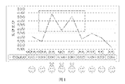
- 1 is a variation of a large viewing angle and a frontal role bias of various representative color systems of a liquid crystal display
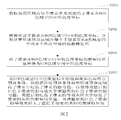
- FIG. 2 is a schematic flow chart showing an implementation of a driving method of a display device according to an embodiment of the present invention
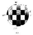
- Figure 3 is a CIE LCH color gamut space system
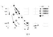
- Figure 4 is a graph showing the change in visual role difference under the condition of 60° horizontal viewing angle under different red color mixing conditions
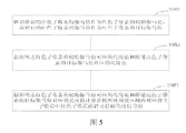
- FIG. 5 is a schematic flowchart showing an implementation of a driving method of a display device according to another embodiment of the present invention.
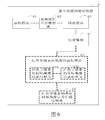
- FIG. 6 is a schematic block diagram of a driving device of a display device according to an embodiment of the present invention.
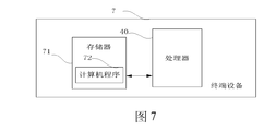
- FIG. 7 is a schematic block diagram of a terminal device according to an embodiment of the present invention.
- the term “if” can be interpreted as “when” or “on” or “in response to determining” or “in response to detecting” depending on the context. .
- the phrase “if determined” or “if detected [condition or event described]” may be interpreted in context to mean “once determined” or “in response to determining” or “once detected [condition or event described] ] or “in response to detecting [conditions or events described]”.
- Fig. 1 is a variation of the large viewing angle and the frontal role of various representative color systems of the liquid crystal display. It is found by Fig. 1 that the color shift phenomenon of the red, green, and blue hue is larger than that of other colors. Serious, therefore, we can improve the overall color shift under large viewing angle by solving the color-shift defects of the R, G, and B hue in the display.
- the liquid crystal material of the liquid crystal display panel itself does not emit light, but emits light through a light source under the liquid crystal material.
- the liquid crystal display panel is composed of a plurality of pixel units, each pixel unit represents an image signal, wherein each pixel unit is composed of three liquid crystal cells, wherein each cell has red (R) under it. , Green (G), Blue (B) filters (or directly use sub-pixels R, G, B as backlights), so that different colors of light can be displayed on the screen through different cells.
- Each of the three cells in each pixel unit has a separate driving signal, and the ratio of the three sub-pixels can be adjusted by a separate driving signal, so that each pixel unit can exhibit a different color.
- FIG. 2 is a schematic diagram of an implementation process of a driving method of a display device according to an embodiment of the present invention. As shown in the figure, the method may include the following steps:
- Step S201 Acquire chromaticity coordinates of the sub-pixel corresponding to each pixel unit in the preset area in the RGB gamut space.
- the liquid crystal display panel is composed of a plurality of pixel units, if the color shift efficiency of each pixel unit is adjusted to be very low, we can first divide the liquid crystal display panel into multiple partitions, each of which The partition is internally composed of multiple pixel units, and the partition size can be set according to the actual situation. For example, the display is divided into multiple partitions (L rows, H columns), each partition can be used as a small area, then the display is equivalent to L ⁇ H small areas. We select one of the small areas as the preset area. This small area is located in the Mth column of the Nth row. The value range of the N is: 1 ⁇ N ⁇ L, and the value range of the M is: 1 ⁇ M ⁇ H.
- the preset area is represented by (N, M), and the value range of N is: 1 ⁇ N ⁇ 5
- the value range of M is: 1 ⁇ M ⁇ 8, and N and M both represent integers.
- the preset area (N, M) can be represented by (3, 6).
- different ways of representing the preset area can be evolved. If one of the partitions can be composed of pixel units of i columns and j rows, then the partition has i ⁇ j pixel units. We illustrate the method of the embodiment of the present invention by adjusting the color shift in one partition as an example.
- the preset area is one of the partitions, and the partition is internally composed of a plurality of pixel units, and each pixel unit is composed of sub-pixels (R, G, B), and each sub-pixel has a corresponding chroma in the gamut space.
- Coordinates for example, grayscale values in RGB gamut space represent chromaticity coordinates, which represent hierarchical levels of different brightness from darkest to brightest, and can represent 256 brightness levels, specifically 0- A numerical representation of 255. We first obtain the grayscale value corresponding to each subpixel in each pixel unit.
- Step S202 calculating data feature values of the plurality of chromaticity coordinates of each sub-pixel in the RGB gamut space according to the chromaticity coordinates of the sub-pixels in the RGB gamut space.
- each sub-pixel for example, the corresponding sub-pixel of the red color.
- the grayscale value in each pixel unit so that each subpixel gets i x j grayscale values.
- the data feature value is a value that can be used to characterize a set of data, or a value that can characterize a data analysis feature.
- the average value may be used as the data feature value of a set of data, that is, the average value of the plurality of gray levels corresponding to each sub-pixel may be obtained, and the average value may include an arithmetic mean, an addend average, and a geometry. Average number.
- the data feature value may also include a variance, or an arithmetic mean after removing the abnormal gray scale data, and the like, and is not limited herein.
- Step S203 converting data feature values of the chromaticity coordinates of the sub-pixels in the RGB gamut space into chromaticity coordinates in the LCH gamut space.
- RGB gamut space is most commonly used in computer graphics because color displays use RGB to produce the desired color. Therefore, the use of RGB gamut space simplifies the construction and design of the system. Moreover, since the RGB gamut space has been used for many years, most of the existing software program modules can be utilized. However, the RGB gamut space is not very efficient when dealing with "real" images. To produce any color within an RGB color cube, all RGB subpixels must have the same bandwidth. This directly leads to a frame memory that requires the same pixel depth and display resolution for each RGB sub-pixel. Moreover, processing an image in the RGB gamut space is usually not the most efficient way.
- L f (R, G, B)
- C f (R, G, B)
- H f (R, G, B).
- L represents brightness
- H hue, that is, color, and the range is 0°-360°, 0° is defined as red, 90° is yellow, 180° is green, and 270° is blue
- C is the purity of hue.
- saturation that is, the vividness of the color, the value range is 0-100, 100 represents the most vivid color, in practical applications, C also represents the display of high and low voltage signals on the LCD display.
- Step S204 if C and H in the chromaticity coordinates in the LCH gamut space meet the preset condition, adjust the gamma value of R in the sub-pixel in the preset area according to the preset condition, so that the adjusted R is The gamma value is greater than the gamma value of the R before the adjustment, the adjusted gray scale of the adjusted R is greater than the data eigenvalue of the gray scale of the G, and the adjusted gray scale of the R is greater than the gray scale data of the B Eigenvalues.
- the preset condition means that C and H in the chromaticity coordinates in the LCH gamut space are severely deviated under the condition.
- the input signal, output represents the output signal, and the gamma value ⁇ is a power exponent and is also referred to as a gamma.
- Equivalent adjustment of the input signal can be achieved by adjusting the gamma value to change the output signal without changing the input signal, or by changing the gamma value without changing the input signal.
- the video source data received by the display is not changed, the image of the video presented to the user is changed by adjusting the gamma value, or the image of the video seen by the user is changed, and the changes are expressed in brightness and color. etc.
- the G and B mixed-color gray-scale signals are 100 gray-scale color difference is 0.01, when R is 100 gray-scale signals, and the G and B mixed-color gray-scale signals are 100 gray-scale color difference. It is 0.003. Therefore, in the embodiment of the present invention, the R gray scale signal can be reduced (reduced gray scale value), so that the Red gray scale signal is close to the G and B mixed color gray scale signals, that is, the gray scale value of R is reduced to be close to the gray of G and B.
- the order value it can be seen from the figure that when the gray scale signals of R, G, and B are close, for example, both are 200, or R is 200, and when G and B are close to 200, the color shift phenomenon is very small because, At this time, the overall color will be biased towards the neutral black and white grayscale color, which will improve the color shift phenomenon under large viewing angles.
- the equivalent gray scale of R cannot be reduced indefinitely.
- the equivalent gray scale of R is still greater than the data characteristic of gray scale of G, which is larger than the data feature value of gray scale of B, because it can be seen from the figure that the gray of R The order must be greater than the gray levels of G and B to improve the color cast.
- the equivalent gray level of R will become smaller, but the equivalent gray level of the adjusted R is greater than the data characteristic of the gray level of G, and the equivalent gray of the adjusted R The order is greater than the data characteristics of the gray scale of G.
- the change in grayscale value in the RGB gamut space is equivalent to the change in brightness, hue, and vividness (saturation) in the LCH gamut space.
- the grayscale values in the RGB gamut space are converted into the chromaticity coordinates in the LCH gamut space by acquiring the data feature values of the plurality of grayscales corresponding to the sub-pixels, so that the method can be applied more widely. If the chromaticity coordinates in the LCH gamut space will exhibit the color shift phenomenon at a large viewing angle, the gamma value of R will be increased, and the gamma value will be increased, and the brightness or equivalent gray level of R will become smaller. When the equivalent gray scale of R is very close to G and B, it also presents a neutral color, and the overall color shift phenomenon will be improved.
- FIG. 5 is a schematic diagram of an implementation of a driving method of a display device according to another embodiment of the present invention. After the step S204, the method may further include the following steps:
- step S501 the gamma value of R before adjustment is taken as the initial gamma value of R, and the gamma value of the adjusted R is taken as the target gamma value of R.
- the gamma value of R before adjustment is used as the initial gamma value of R, and the adjusted The gamma value of R is taken as the target gamma value of R.
- Step S502 acquiring a brightness value corresponding to the initial gamma value of the R and a brightness value corresponding to the target gamma value of the R.
- the color gamut phenomenon at a large viewing angle is improved by adjusting the gamma value of R
- the brightness of R at the positive viewing angle is Changed, so that the color of R changes under the positive viewing angle, so that the color combined by the sub-pixels also changes, so we need to obtain the brightness value corresponding to the initial gamma value of R and the target gamma of R
- the brightness value corresponding to the value to see how much the brightness changes, in order to restore the brightness value under the positive viewing angle, and the performance of the original color is not affected by adjusting the gamma value of R.
- the luminance value corresponding to the initial gamma value of R is obtained by the following formula:
- the luminance value corresponding to the target gamma value of the R is obtained by the following formula:
- the L N, M R represents a luminance value corresponding to an initial gamma value of the R
- the L′ N, M R represents a luminance value corresponding to a target gamma value of the R
- the LR (255) represents The gray scale of R is a luminance value at 255
- g R represents a data eigenvalue of the gray scale of R in each pixel unit in the preset region
- ⁇ R represents an initial gamma value of R
- ⁇ 'R represents R
- the target gamma value is not limited to this.
- the target gamma value of R is greater than the initial gamma value of R , and g R is a value of ⁇ 255, L' N, M R is actually darkened relative to L N , M R That is, after the gamma value of R is increased, the brightness of R becomes dark. It should be noted that the above is only one way of obtaining the brightness value corresponding to the initial gamma value of R and the brightness value corresponding to the target gamma value of R. In practical applications, it may also be acquired according to other methods.
- Step S503 calculating, according to the brightness value corresponding to the initial gamma value of the R and the brightness value corresponding to the target gamma value of the R, a backlight target brightness signal value of R in the corresponding backlight sub-pixel in the preset area.
- the presentation of the brightness is driven by the input luminance signal, and the change in the luminance value also needs to be adjusted to the magnitude of the luminance signal value. Therefore, we can calculate the brightness value of the backlight target according to the brightness value corresponding to the initial gamma value of R and the brightness value corresponding to the target gamma value of R and the current brightness signal value, and the backlight target brightness signal value can make R The brightness presented is restored to the brightness presented prior to adjusting the gamma of R.
- the backlight target brightness of R in the corresponding backlight sub-pixel in the preset area may be calculated according to the brightness value corresponding to the initial gamma value of the R and the brightness value corresponding to the target gamma value of the R.
- the signal value is specifically:
- the A'N, M R represents a backlight target luminance signal value corresponding to R in the backlight sub-pixel in the preset area
- a N, M R represents the current backlight luminance signal value of R in the corresponding backlight sub-pixel in the preset area
- L N, M R represents a luminance value corresponding to an initial gamma value of R in a sub-pixel in the preset region
- the L′ N, M R represents a target gamma value corresponding to R in the sub-pixel in the preset region.
- the brightness value, the N, M respectively represent the number of rows and the number of columns of the preset area in the divided plurality of areas, but is not limited thereto.
- the backlight target luminance signal value of R is specifically:
- adjusting the gamma value of R in the sub-pixel in the preset area according to the preset condition is specifically :
- the H represents the hue of the preset area in the LCH gamut space
- the range in which the C and H in the LCH gamut space are respectively in the case where the color shift phenomenon is severe we find the range in which the C and H in the LCH gamut space are respectively in the case where the color shift phenomenon is severe, and the range is used as a preset condition, that is, the values of C and H meet the preset conditions or When it is within the preset range, it indicates that the color shift phenomenon is serious under large viewing angle.
- different preset conditions may be set according to the range of C and H when the color shift is severe under a large viewing angle, and different target gamma values are set corresponding to different preset conditions, corresponding to each target gamma value. It is not necessary to be larger than the initial gamma value. It is determined according to the values of C and H in the preset conditions.
- the target gamma value can also be an empirical value. After adjusting the target gamma value, the color shift phenomenon is improved. Setting different target gamma values may improve the degree of color shift phenomenon.
- the method of improving the color shift is to make the color after RGB color mixing close to neutral, so that the color shift phenomenon close to the neutral color is improved.
- a plurality of preset conditions are set according to the range of L and C when the color shift phenomenon is serious, and each of the preset conditions corresponds to a different target gamma value, so that as long as H and C meet the preset condition,
- the preset condition adjusts the gamma value of R to improve the color shift phenomenon at a large viewing angle.
- FIG. 6 is a schematic block diagram of a driving device of a display device according to an embodiment of the present invention. For convenience of description, only parts related to the embodiment of the present invention are shown.
- the driving device 6 of the display device may be a software unit, a hardware unit or a combination of soft and hard units built in a terminal device (display, television, etc.), or may be integrated into the terminal device as a separate pendant.
- the driving device 6 of the display device comprises:
- the obtaining module 61 is configured to acquire chromaticity coordinates of the sub-pixel corresponding to each pixel unit in the preset region in the RGB gamut space;
- the data feature value calculation module 62 is configured to separately calculate data of multiple chromaticity coordinates of each sub-pixel in the RGB gamut space according to the chromaticity coordinates of the sub-pixels in the RGB gamut space. Eigenvalues;
- a conversion module 63 configured to convert data feature values of chromaticity coordinates of the sub-pixels in the RGB gamut space into chromaticity coordinates in the LCH gamut space;
- the processing module 64 is configured to adjust the gamma values of R in the sub-pixels in the preset area according to the preset condition, if C and H in the chromaticity coordinates in the LCH gamut space meet the preset condition, so that The adjusted gamma value of R is greater than the gamma value of R before adjustment, and the adjusted gray scale of R is greater than the data feature value of gray scale of G, and the adjusted gray scale of R is greater than B The data feature value of the grayscale.
- it also includes:
- a luminance value obtaining module 65 of the third sub-pixel configured to use a gamma value of R before adjustment as an initial gamma value of R, a gamma value of the adjusted R as a target gamma value of R, and acquire the a luminance value corresponding to an initial gamma value of R and a luminance value corresponding to a target gamma value of the R;
- the backlight target luminance signal value determining module 66 of the third sub-pixel is configured to obtain the preset region according to the luminance value corresponding to the initial gamma value of the R and the luminance value corresponding to the target gamma value of the R. Corresponding to the backlight target luminance signal value of R in the backlight sub-pixel.
- the backlight target luminance signal value determining module 66 of the third sub-pixel is configured to calculate, according to the luminance value corresponding to the initial gamma value of the R and the luminance value corresponding to the target gamma value of the R.
- the backlight target luminance signal value determining module 66 of the third sub-pixel is specifically configured to:
- the A'N, M R represents a backlight target luminance signal value corresponding to R in the backlight sub-pixel in the preset area
- a N, M R represents the current backlight luminance signal value of R in the corresponding backlight sub-pixel in the preset area
- L N, M R represents a luminance value corresponding to an initial gamma value of R in a sub-pixel in the preset region
- the L′ N, M R represents a target gamma value corresponding to R in the sub-pixel in the preset region.
- the brightness value, the N, M respectively represent the number of rows and the number of columns of the preset area in the divided plurality of areas.
- the brightness value obtaining module 65 of the third sub-pixel includes:
- the initial luminance value obtaining unit 6511 of the third sub-pixel is configured to obtain a luminance value corresponding to the initial gamma value of the R by using the following formula:
- the target luminance value obtaining unit 652 of the third sub-pixel is configured to obtain a luminance value corresponding to the target gamma value of the R by using the following formula:
- the L N, M R represents a luminance value corresponding to an initial gamma value of the R
- the L′ N, M R represents a luminance value corresponding to a target gamma value of the R
- the LR (255) represents The gray scale of R is a luminance value at 255
- g R represents a data eigenvalue of the gray scale of R in each pixel unit in the preset region
- ⁇ R represents an initial gamma value of R
- ⁇ 'R represents R Target gamma value.
- processing module 64 is specifically configured to:
- the H represents the hue of the preset area in the LCH gamut space
- the data feature values include: an arithmetic mean, an addend average, a geometric mean, and a variance.
- each functional module and unit in the embodiment may be integrated into one processing module, or each module or unit may exist physically separately, or two or more units may be integrated into one module, and the integrated module and unit are It can be implemented in the form of hardware, or it can be implemented in the form of software function modules and units.
- FIG. 7 is a schematic block diagram of a terminal device according to an embodiment of the present invention.
- the terminal device 7 of this embodiment includes: one or more processors 70, a memory 71, and a computer program 72 stored in the memory 71 and operable on the processor 70.
- the processor 70 executes the computer program 72, the steps in the embodiment of the driving method of each of the above display devices are implemented, for example, steps S201 to S204 shown in FIG.
- the processor 70 implements the functions of the modules in the embodiment of the driving device of the display device when the computer program 72 is executed, such as the functions of the modules 61 to 64 shown in FIG. If the terminal device is a display, it should also include a display panel.
- the computer program 72 can be partitioned into one or more modules/units that are stored in the memory 71 and executed by the processor 70 to complete this invention.
- the one or more modules/units may be a series of computer program instruction segments capable of performing a particular function, the instruction segments being used to describe the execution of the computer program 72 in the terminal device 7.
- the computer program 72 can be segmented into an acquisition module, a data feature value calculation module, a conversion module, and a processing module.
- the acquiring module is configured to acquire chromaticity coordinates of the sub-pixels corresponding to each pixel unit in the preset area in the RGB gamut space;
- the data feature value calculation module is configured to calculate, according to the chromaticity coordinates of the sub-pixels in the RGB gamut space, a plurality of chromaticity coordinates of each sub-pixel in the RGB gamut space in the preset region. Data feature value;
- the conversion module is configured to convert data feature values of chromaticity coordinates of the sub-pixels in the RGB gamut space into chromaticity coordinates in the LCH gamut space;
- the processing module is configured to adjust the gamma value of R in the sub-pixel in the preset area according to the preset condition, if C and H in the chromaticity coordinates in the LCH gamut space meet the preset condition,
- the gamma value of the adjusted R is greater than the gamma value of the R before the adjustment
- the equivalent gray level of the adjusted R is greater than the data eigenvalue of the gray scale of the G
- the adjusted gray scale of the adjusted R is greater than B.
- the data feature value of the grayscale is configured to adjust the gamma value of R in the sub-pixel in the preset area according to the preset condition, if C and H in the chromaticity coordinates in the LCH gamut space meet the preset condition,
- the gamma value of the adjusted R is greater than the gamma value of the R before the adjustment
- the equivalent gray level of the adjusted R is greater than the data eigenvalue of the gray scale of the G
- the adjusted gray scale of the adjusted R
- the terminal device includes but is not limited to the processor 70 and the memory 71. It will be understood by those skilled in the art that FIG. 7 is only an example of the terminal device 7, and does not constitute a limitation of the terminal device 7, and may include more or less components than those illustrated, or combine some components or different components.
- the terminal device may further include an input device, an output device, a network access device, a bus, and the like.
- the processor 70 may be a central processing unit (CPU), or may be another general-purpose processor, a digital signal processor (DSP), or an application specific integrated circuit (ASIC). , Field-Programmable Gate Array (FPGA) or other programmable logic devices, discrete gate or transistor logic devices, discrete hardware components, etc.
- the general purpose processor may be a microprocessor or the processor or any conventional processor or the like, which is a control center of the terminal device, and connects various parts of the entire terminal device using various interfaces and lines.
- the memory 71 may be an internal storage unit of the terminal device 7, such as a hard disk or a memory of the terminal device 7.
- the memory 71 may also be an external storage device of the terminal device 7, for example, a plug-in hard disk provided on the terminal device 7, a smart memory card (SMC), and a secure digital (SD). Card, flash card, etc.
- the memory 71 may also include both an internal storage unit of the terminal device 7 and an external storage device.
- the memory 71 is used to store the computer program and other programs and data required by the terminal device.
- the memory 71 can also be used to temporarily store data that has been output or is about to be output.
- the disclosed terminal device, the driving device, and the driving method may be implemented in other manners.
- the device embodiments described above are merely illustrative.
- the division of the modules or units is only a logical function division.
- there may be another division manner for example, multiple units or components may be used. Combinations can be integrated into another system, or some features can be ignored or not executed.
- the mutual coupling or direct coupling or communication connection shown or discussed may be an indirect coupling or communication connection through some interface, device or unit, and may be in electrical, mechanical or other form.
- the units described as separate components may or may not be physically separated, and the components displayed as units may or may not be physical units, that is, may be located in one place, or may be distributed to multiple network units. Some or all of the units may be selected according to actual needs to achieve the purpose of the solution of the embodiment.
- each functional unit in each embodiment of the present invention may be integrated into one processing unit, or each unit may exist physically separately, or two or more units may be integrated into one unit.
- the above integrated unit can be implemented in the form of hardware or in the form of a software functional unit.
- the integrated modules/units if implemented in the form of software functional units and sold or used as separate products, may be stored in a computer readable storage medium. Based on such understanding, the present invention implements all or part of the processes in the foregoing embodiments, and may also be completed by a computer program to instruct related hardware.
- the computer program may be stored in a computer readable storage medium. The steps of the various method embodiments described above may be implemented when the program is executed by the processor.
- the computer program comprises computer program code, which may be in the form of source code, object code form, executable file or some intermediate form.
- the computer readable medium may include any entity or device capable of carrying the computer program code, a recording medium, a USB flash drive, a removable hard disk, a magnetic disk, an optical disk, a computer memory, a read-only memory (ROM). , random access memory (RAM, Random Access Memory), electrical carrier signals, telecommunications signals, and software distribution media. It should be noted that the content contained in the computer readable medium may be appropriately increased or decreased according to the requirements of legislation and patent practice in a jurisdiction, for example, in some jurisdictions, according to legislation and patent practice, computer readable media It does not include electrical carrier signals and telecommunication signals.
Landscapes
- Engineering & Computer Science (AREA)
- Chemical & Material Sciences (AREA)
- Crystallography & Structural Chemistry (AREA)
- Physics & Mathematics (AREA)
- Computer Hardware Design (AREA)
- General Physics & Mathematics (AREA)
- Theoretical Computer Science (AREA)
- Control Of Indicators Other Than Cathode Ray Tubes (AREA)
- Liquid Crystal Display Device Control (AREA)
Abstract
一种显示装置的驱动方法,包括:获取预设区域内每个像素单元对应的子像素在RGB色域空间中的色度坐标;根据所述子像素在RGB色域空间中的色度坐标,分别计算所述预设区域内每个子像素在RGB色域空间中的多个色度坐标的数据特征值;将子像素在RGB色域空间中的色度坐标的数据特征值转换为LCH色域空间中的色度坐标;若LCH色域空间中色度坐标中的饱和度和色相符合预设条件,则根据所述预设条件调整所述预设区域内子像素中第三子像素的伽马值。
Description
本发明属于显示技术领域,尤其涉及一种显示装置的驱动方法及驱动装置。
由于液晶显示器(Liquid Crystal Display,LCD)屏幕具有节能环保、轻便等优势,目前在显示器领域得到广泛的应用,由于直下式的LCD屏幕具有较高的对比度和较快的响应速度,获得市场上的普遍认可。
但是直下式的LCD屏幕具有大视角色偏现象比较严重的缺点,并且这种缺点是直下式LCD屏幕的设计所固有的,即直下式LCD屏幕本身的设计结构造成大视角下色偏的现象无法完全消除。
发明内容
有鉴于此,本发明实施例提供了一种显示装置的驱动方法及驱动装置,以改善目前显示装置大视角下的色偏现象。
本发明实施例提供了一种显示装置的驱动方法,包括:
获取预设区域内每个像素单元对应的子像素在RGB色域空间中的色度坐标;
根据所述子像素在RGB色域空间中的色度坐标,分别计算所述预设区域内每个子像素在RGB色域空间中的多个色度坐标的数据特征值;
将子像素在RGB色域空间中的色度坐标数据特征值转换为LCH色域空间中的色度坐标;
若LCH色域空间中色度坐标中的色相和饱和度符合预设条件,则根据所述预设条件调整所述预设区域内子像素中第三子像素的伽马值,以使得调整后的第三子像素的伽马值大于调整前的第三子像素的伽马值,调整后的第三子像素的等效灰阶大于第一子像素的灰阶的数据特征值,且调整后的第三子像素的等效灰阶大于第二子像素的灰阶的数据特征值。
本发明实施例还提供了一种显示装置的驱动装置,包括:
获取模块,用于获取预设区域内每个像素单元对应的子像素在RGB色域空间中的色度坐标;
数据特征值计算模块,用于根据所述子像素在RGB色域空间中的色度坐标,分别计算所述预设区域内每个子像素在RGB色域空间中的多个色度坐标的数据特征值;
转换模块,用于将子像素在RGB色域空间中的色度坐标的数据特征值转换为LCH色域空间中的色度坐标;
处理模块,用于若LCH色域空间中色度坐标中的色相和饱和度符合预设条件,则根据所述预设条件分别调整所述预设区域内子像素中第三子像素的伽马值,以使得调整后的第三子像素的伽马值大于调整前的第三子像素的伽马值,调整后的第三子像素的等效灰阶大于第一子像素的灰阶的数据特征值,且调整后的第三子像素的等效灰阶大于第二子像素的灰阶的数据特征值。
本发明实施例还提供了一种显示装置的驱动方法,包括:
获取预设区域内每个像素单元对应的子像素在RGB色域空间中的色度坐标;
根据所述子像素在RGB色域空间中的色度坐标,分别计算所述预设区域内每个子像素在RGB色域空间中的多个色度坐标的数据特征值;
将子像素在RGB色域空间中的色度坐标的数据特征值转换为LCH色域空间中的色度坐标;
若LCH色域空间中色度坐标中的饱和度和色相符合预设条件,则根据所述预设条件调整所述预设区域内子像素中第三子像素的伽马值,以使得调整后的第三子像素的伽马值大于调整前的第三子像素的伽马值,调整后的第三子像素的等效灰阶大于第一子像素的灰阶的数据特征值,且调整后的第三子像素的等效灰阶大于第二子像素的灰阶的数据特征值;
将调整前的第三子像素的伽马值作为第三子像素的初始伽马值,调整后的第三子像素的伽马值作为第三子像素的目标伽马值;
获取所述第三子像素的初始伽马值对应的亮度值和所述第三子像素的目标伽马值对应的亮度值;
根据所述第三子像素的初始伽马值对应的亮度值和所述第三子像素的目标伽马值对应的亮度值计算获得所述预设区域内对应背光子像素中第三子像素的背光目标亮度信号值;
所述若LCH色域空间中色度坐标中的饱和度和色相符合预设条件,则根据所述预设条件调整所述预设区域内子像素中第三子像素的伽马值具体为:
若H∈(345°,360°],且C∈[C
TL1,C
TH1],则γ'R=γR
1,且


若H∈(330°,345°],且C∈[C
TL2,C
TH2],则γ'R=γR
2,且


若H∈(315°,330°],且C∈[C
TL3,C
TH3],则γ'R=γR
3,且


若H∈(0°,15°],且C∈[C
TL4,C
TH4],则γ'R=γR
4,且

若H∈(15°,30°],且C∈[C
TL5,C
TH5],则γ'R=γR
5,且


若H∈(30°,45°],且C∈[C
TL6,C
TH6],则γ'R=γR
6,且


所述H表示预设区域在LCH色域空间中的色相;所述C表示预设区域在LCH色域空间中的色相的饱和度,0≤C
TLi<100,0<C
THi≤100,C
THi≥C
TLi,i=1,2,3,4,5,6;所述γ'R表示调整后的第三子像素的伽马值,
 表示调整第三子像素的伽马值后第三子像素的等效灰阶,i=1,2,3,4,5。
本发明实施例还提供了一种终端设备,包括存储器、处理器以及存储在所述存储器中并可在所述处理器上运行的计算机程序,所述处理器执行所述计算机程序时实现本发明实施例第一方面提供的所述方法的步骤。
本发明实施例还提供了一种计算机可读存储介质,所述计算机可读存储介质存储有计算机程序,所述计算机程序被一个或多个处理器执行时实现本发明实施例第一方面提供的所述方法的步骤。
本发明实施例通过先获取预设区域内每个像素单元对应的子像素(第三子像素、第一子像素、第二子像素,或者,R、G、B)在RGB色域空间中的色度坐标,RGB空间中的色度坐标可以用灰阶表示,由于每个像素单元内都会有一个第三子像素的灰阶值、一个第一子像素的灰阶值,一个第二子像素的灰阶值,根据获取的每个像素单元的子像素的灰阶分别计算每个子像素对应的多个灰阶值的数据特征值,将子像素的灰阶的数据特征值转换为在LCH色域空间中的色度坐标;若LCH色域空间中色度坐标中的色相和饱和度符合预设条件,所述预设条件是指大视角下色偏现象严重时色相和饱和度的范围值,则将子像素中第三子像素的输入伽马信号调大,这样调大第三子像素的伽马值后,第三子像素在大视角下的亮度比例进一步相对于第二子像素和第一子像素下降,使得颜色呈现中性色彩,中性色彩使得正视角与大视角色差获得改善,及改善了大视角下的色偏现象。
为了更清楚地说明本发明实施例中的技术方案,下面将对实施例或现有技术描述中所需要使用的附图作简单地介绍,显而易见地,下面描述中的附图仅仅是本发明的一些实施例,对于本领域普通技术人员来讲,在不付出创造性劳动性的前提下,还可以根据这些附图获得其他的附图。
图1是液晶显示器各种代表性的色系的大视角与正视角色偏的变化;
图2是本发明一实施例提供的显示装置的驱动方法的实现流程示意图;
图3是CIE LCH色域空间系统;
图4是60°水平视角在红色系不同混色条件下的视角色差变化情况;
图5是本发明又一实施例提供的显示装置的驱动方法的实现流程示意图;
图6是本发明一实施例提供的显示装置的驱动装置的示意框图;
图7是本发明一实施例提供的终端设备的示意框图。
以下描述中,为了说明而不是为了限定,提出了诸如特定系统结构、技术之类的具体细节,以便透彻理解本发明实施例。然而,本领域的技术人员应当清楚,在没有这些具体细节的其它实施例中也可以实现本发明。在其它情况中,省略对众所周知的系统、装置、电路以及方法的详细说明,以免不必要的细节妨碍本发明的描述。
应当理解,当在本说明书和所附权利要求书中使用时,术语“包括”指示所描述特征、整体、步骤、操作、元素和/或组件的存在,但并不排除一个或多个其它特征、整体、步骤、操作、元素、组件和/或其集合的存在或添加。
还应当理解,在此本发明说明书中所使用的术语仅仅是出于描述特定实施例的目的而并不意在限制本发明。如在本发明说明书和所附权利要求书中所使用的那样,除非上下文清楚地指明其它情况,否则单数形式的“一”、“一个”及“该”意在包括复数形式。
还应当进一步理解,在本发明说明书和所附权利要求书中使用的术语“和/或”是指相关联列出的项中的一个或多个的任何组合以及所有可能组合,并且包括这些组合。
如在本说明书和所附权利要求书中所使用的那样,术语“如果”可以依据上下文被解释为“当...时”或“一旦”或“响应于确定”或“响应于检测到”。类似地,短语“如果确定”或“如果检测到[所描述条件或事件]”可以依据上下文被解释为意指“一旦确定”或“响应于确定”或“一旦检测到[所描述条件或事件]”或“响应于检测到[所描述条件或事件]”。
图1是液晶显示器各种代表性的色系的大视角与正视角色偏的变化,通过图1我们发现,偏红色、绿色、蓝色色相的色系大视角下色偏现象比其它色系更严重,因此,我们可以通过解决显示器中R、G、B色相的色偏缺陷来改善大视角下的整体色偏现象。为了后续便于描述,我们将第三子像素用R表示、第一子像素用G表示,第二子像素用B表示,LCH色域空间中的饱和度用C表示,色相用H表示。
在介绍色偏现象之后,我们还需要介绍液晶显示器,液晶显示面板的液晶材料本身是不发光的,而是通过液晶材料下面的光源发射光线。液晶显示面板是由多个像素单元组成的,每个像素单元就代表了一个影像信号,其中每个像素单元又由三个液晶单元格组成,其中每个单元格下面都分别有红色(R)、绿色(G)、蓝色(B)过滤器(或者直接使用子像素R、G、B作为背光源),这样通过不同单元格的光线就可以在屏幕上显示出不同颜色。每个像素单元中的三个单元格都有单独的驱动信号,通过单独的驱动信号就可以调节三个子像素的配比,从而使得每个像素单元都可以呈现出不同的颜色。
为了说明本发明所述的技术方案,下面通过具体实施例来进行说明。
图2是本发明一个实施例提供的一种显示装置的驱动方法的实现流程示意图,如图所示该方法可以包括以下步骤:
步骤S201,获取预设区域内每个像素单元对应的子像素在RGB色域空间中的色度坐标。
在一个实施例中,由于液晶显示面板是有很多个像素单元组成,如果单独的调节每一个像素单元的色偏效率会非常低,所以我们可以先将液晶显示面板分为多个分区,每个分区内部由多个像素单元组成,分区大小可以根据实际情况自行设置。例如,将显示器划分为多个分区(L行、H列),每个分区可以作为一个小区域,那么显示器相当于是由L×H个小区域组成的。我们选取其中一个小区域作为预设区域,这个小区域位于第N行第M列,所述N的取值范围为:1≤N≤L,所述M的取值范围为:1≤M≤H。也就是说,如果将显示器的显示面板划分为5行8列,那么L=5,H=8,那么预设区域用(N,M)表示,N的取值范围是:1≤N≤5,M的取值范围为:1≤M≤8,N和M均表示整数。假设我们选取的预设区域是第3行第6列,那么预设区域(N,M)就可以用(3,6)表示。当然,根据以上内容还可以演变出不同的表示预设区域的方式。假如其中一个分区可以是由i列、j行的像素单元组成,那么该分区就有i×j个像素单元,我们通过调节一个分区中的色偏为例说明本发明实施例的方法。
所述预设区域就是其中一个分区,该分区内部由多个像素单元,同时每个像素单元都由子像素(R、G、B)组成,每个子像素都会有对应的色域空间中的色度坐标,例如,RGB色域空间中使用灰阶值表示色度坐标,所述灰阶代表由最暗到最亮之间不同亮度的层次级别,能表现出256个亮度层次,具体可以用0-255的数值表示。我们先获取每个像素单元中的每个子像素对应的灰阶值。
步骤S202,根据所述子像素在RGB色域空间中的色度坐标,分别计算所述预设区域内每个子像素在RGB色域空间中的多个色度坐标的数据特征值。
在一个实施例中,在获取了每个像素单元中的每个子像素在RGB色域空间中的色度坐标(灰阶值)后,我们可以再获取每个子像素(例如红色色相对应的子像素)在每个像素单元中的灰阶值,这样每个子像素就得到i×j个灰阶值。所说数据特征值是能够用来表征一组数据的值,或者是能够刻画数据分析特征的值。在一个实施例中,可以采用平均值来作为一组数据的数据特征值,也就是得到每个子像素对应的多个灰阶的平均值,平均值可以包括算数平均数、加数平均数、几何平均数。需要说明的是,数据特征值还可以包括方差、或者去掉异常灰阶数据之后的算术平均数等,在此不做限制。
步骤S203,将子像素在RGB色域空间中的色度坐标的数据特征值转换为LCH色域空间中的色度坐标。
在一个实施例中,RGB色域空间在计算机图形中使用最为普遍,因为彩色显示器使用RGB来产生所需的颜色。所以,选用RGB色域空间简化了系统的构建和设计。而且,由于RGB色域空间使用了很多年,所以可以利用大部分现有的软件程序模块。然而,RGB色域空间在处理"现实"图像时,它的效率并不是很高。要产生RGB颜色立方体内的任意颜色,所有的RGB子像素都必须有相同的带宽。这就直接导致了每个RGB子像素需要像素深度和显示分辨力都相同的帧存储器。而且,在RGB色域空间内处理一幅图像通常也不是最有效的方式。举个例子,我们要改变一个像素点的亮度或色度,我们必须从帧缓冲器中读出所有的RGB颜色值,然后计算亮度或色度,然后对它们进行相应的更改,计算出新的RGB值,写回帧缓冲器。如果系统访问的是直接以亮度和色度存储的图像,一些处理步骤就会更快了。由于这些以及其它的原因,很多视频标准使用亮度和两个色差信号。所以为了方便处理"现实"图像,实际 应用中,可能会采用其它色域空间,例如本发明实施例提供的LCH色域空间,所以我们将子像素在RGB色域空间中的色度坐标的数据特征值转换为LCH色域空间中的色度坐标。
图3是CIE LCH色域空间系统,LCH色域空间中的色度坐标分别用L、C、H表示。L、C、H的数值可以通过RGB色域空间中的色度坐标R、G、B转化而来,例如,L=f(R、G、B),C=f(R、G、B),H=f(R、G、B)。L表示亮度;H表示色相,也就是颜色,取值范围为0°-360°,定义0°为红色,90°为黄色,180°为绿色,270°为蓝色;C表示色相的纯度,或者饱和度,也就是颜色的鲜艳程度,取值范围为0-100,100代表颜色最鲜艳,在实际应用中,C也代表了LCD显示屏显示高低压信号的呈现。
步骤S204,若LCH色域空间中色度坐标中的C和H符合预设条件,则根据所述预设条件调整所述预设区域内子像素中R的伽马值,以使得调整后的R的伽马值大于调整前的R的伽马值,调整后的R的等效灰阶大于G的灰阶的数据特征值,且调整后的R的等效灰阶大于B的灰阶的数据特征值。
在一个实施例中,所述预设条件是指LCH色域空间中色度坐标中的C和H在该条件下时色偏现象严重。这样,在色偏现象严重时,我们可以通过调节显示屏中RGB子像素的各项参数来改善大视角下液晶显示面板的色偏现象。例如调节子像素的输入伽马信号,所述输入伽马信号具体用伽马值表示,所述伽马值实际上是输出和输入的一种关系值,可以通过公式output=input
γ,input表示输入的信号,output表示输出的信号,伽马值γ是幂指数,也被成为灰度系数。通过调节伽马值就可以在不改变输入信号的情况下改变输出信号,或者不改变输入信号的情况下改变伽马值就可以实现等效调节输入信号。通俗的讲,不改变显示器接收到的视频源数据,通过调整伽马值使得呈现给用户的视频的图像发生变化,或者使得用户看到的视频的图像发生了变化,这些变化表现在亮度、色彩等方面。
为了进一步解释色偏的原因,我们比较正视角和大视角下RGB子像素的灰阶关系,以正视角(0°)混色灰阶为R160、G50、B50为例,对应正视角RX、GY、BZ与全灰阶R255、G255、B255比例分别为37%、3%、3%混色,而在大视角下(60°)RX、GY、BZ与全灰阶R255、G255、B255比例分别为54%、23%、28%混色,可见正视角混色与大视角混色的RX、GY、BZ比例完全不同,也就是说同样的灰阶值(输入参数信号)在大视角下比在正视角下表现出的R和G、R和B之间的亮度比例变大了,换言之,大视角下蓝色色相和绿色色相相比于红色色相的比例无法忽视了,造成大视角下的红色色相不如正视角下的红色色相明显,这样大视角下就出现了色偏现象。需要说明的是,该示例仅仅是用于举例,在实际中,不同视角、不同的混色条件,最后表现出的色偏现象有可能并不一样。
为了进一步获得需要调节的参数,我们通过图4说明60°水平视角在红色系不同混色条件下的视角色差变化情况,如图4所示,当相同红色色相(红色灰阶相同)对应相同的G、B灰阶信号,混色R信号越低(红色色相的灰阶)时可以发现色差(色偏)越小,例如,当R为200灰阶信号,G、B混色灰阶信号为100灰阶的色差为0.015,当R为160灰阶信号,G、B混色灰阶信号为100灰阶的色差为0.01,当R为100灰阶信号,G、B混色灰阶信号为100灰阶的色差为0.003。因此本发明实施例可以通过将R灰阶信号降低(降低灰阶值),使得Red灰阶信号接近G、B混色灰阶信号,也就是说R的灰阶值降低至接近G、B的灰阶值, 通过图中可以看出当R、G、B的灰阶信号接近时,例如,都为200时,或者R为200,G、B为接近200时,色偏现象非常小,因为,这时整体颜色会偏向中性黑白灰阶颜色,这样就能够改善大视角下的色偏现象。但是R的等效灰阶不能无限制的降低,R的等效灰阶还是要大于G的灰阶的数据特征,大于B的灰阶的数据特征值,因为通过图可以看出,R的灰阶必须大于G和B的灰阶才能使得色偏想象改善。所以,R的伽马值调大后,R的等效灰阶会变小,但是调整后的R的等效灰阶要大于G的灰阶的数据特征,且调整后的R的等效灰阶要大于G的灰阶的数据特征。
RGB色域空间中的灰阶值变化相当于LCH色域空间中的亮度、色相、鲜艳度(饱和度)变化了。
本发明实施例通过获取子像素对应的多个灰阶的数据特征值,将RGB色域空间中的灰阶值转化为LCH色域空间中色度坐标,使得该方法可应用的场合更广,若LCH色域空间中色度坐标会呈现大视角下的色偏现象,则将R的伽马值调大,伽马值调大后,R的亮度或者等效灰阶就会变小,当R的等效灰阶变的与G和B很接近时,也就呈现了偏中性的色彩,整体的色偏现象就会改善。
图5是本发明又一实施例提供的一种显示装置的驱动方法的实现示意图,如图所示该方法在步骤S204之后,还可以包括以下步骤:
步骤S501,将调整前的R的伽马值作为R的初始伽马值,调整后的R的伽马值作为R的目标伽马值。
在一个实施例中,为了方便区分调整R的伽马值之前的数值和调整调整R的伽马值之后的数值,将调整前的R的伽马值作为R的初始伽马值,调整后的R的伽马值作为R的目标伽马值。
步骤S502,获取所述R的初始伽马值对应的亮度值和所述R的目标伽马值对应的亮度值。
在一个实施例中,虽然通过调整R的伽马值使得大视角下的色偏现象改善了,但是由于调整伽马值后亮度也会有相应的影响,所以,在正视角下R的亮度是变化了的,这样正视角下R的颜色就改变了了,使得通过子像素组合在一起的颜色也发生了变化,所以我们需要获取R的初始伽马值对应的亮度值和R的目标伽马值对应的亮度值,查看亮度变化了多少,以便于恢复正视角下的亮度值,不会因为调整R的伽马值使得原色彩的表现受到影响。
例如可以为,我们通过以下方式可以获得R的初始伽马值对应的亮度值和R的目标伽马值对应的亮度值。
所述R的初始伽马值对应的亮度值通过以下公式获取:

所述R的目标伽马值对应的亮度值通过以下公式获取:

所述L
N,MR表示所述R的初始伽马值对应的亮度值,所述L'
N,MR表示所述R的目标伽马值对应的亮度值;所述LR(255)表示R的灰阶为255时的亮度值,g
R表示预设区域内每个像素单元中的R的灰阶的数据特征值;γR表示R的初始伽马值,所述γ'R表示R的目标伽 马值,然不限于此。
在一个实施例中,由于R的目标伽马值大于R的初始伽马值,而g
R是≤255的值,所以L'
N,MR相对于L
N,MR实际上是变暗了,也就是R的伽马值调大后,R的亮度变暗了。需要说明的是,以上仅仅是R的初始伽马值对应的亮度值和R的目标伽马值对应的亮度值的一种获取方式,在实际应用中,还可以根据其它方式获取。
步骤S503,根据所述R的初始伽马值对应的亮度值和所述R的目标伽马值对应的亮度值计算获得所述预设区域内对应背光子像素中R的背光目标亮度信号值。
在一个实施例中,亮度的呈现是由输入的亮度信号驱动的,亮度值的变化也需要调整亮度信号值的大小来实现。所以我们可以根据R的初始伽马值对应的亮度值和所述R的目标伽马值对应的亮度值以及当前的亮度信号值来计算获得背光目标亮度信号值,背光目标亮度信号值能够使得R呈现出的亮度恢复至调整R的伽马值之前所呈现的的亮度。
例如可以为,所述根据所述R的初始伽马值对应的亮度值和所述R的目标伽马值对应的亮度值计算获得所述预设区域内对应背光子像素中R的背光目标亮度信号值具体为:

所述A'
N,MR表示预设区域内对应背光子像素中R的背光目标亮度信号值,A
N,MR表示预设区域内对应背光子像素中R当前的背光亮度信号值;所述L
N,MR表示所述预设区域内子像素中R的初始伽马值对应的亮度值,所述L'
N,MR表示所述预设区域内子像素中R的目标伽马值对应的亮度值,所述N,M分别表示所述预设区域在划分的多个区域中的行数和列数,然不限于此。
若R的初始伽马值对应的亮度值和R的目标伽马值对应的亮度值采用步骤S402中的方式获取,则R的背光目标亮度信号值具体为:

作为本发明又一实施例,若LCH色域空间中色度坐标中的C和H符合预设条件,则根据所述预设条件调整所述预设区域内子像素中R的伽马值具体为:
若H∈(345°,360°],且C∈[C
TL1,C
TH1],则γ'R=γR
1,且


若H∈(330°,345°],且C∈[C
TL2,C
TH2],则γ'R=γR
2,且


若H∈(315°,330°],且C∈[C
TL3,C
TH3],则γ'R=γR
3,且


若H∈(0°,15°],且C∈[C
TL4,C
TH4],则γ'R=γR
4,且


若H∈(15°,30°],且C∈[C
TL5,C
TH5],则γ'R=γR
5,且


若H∈(30°,45°],且C∈[C
TL6,C
TH6],则γ'R=γR
6,且


所述H表示预设区域在LCH色域空间中的色相;所述C表示预设区域在LCH色域空间中的色相的饱和度,0≤C
TLi<100,0<C
THi≤100,C
THi≥C
TLi,i=1,2,3,4,5,6;所述γ'R表示调整后的R的伽马值,
 表示调整R的伽马值后R的等效灰阶,i=1,2,3,4,5。
在一个实施例中,我们找出色偏现象严重时,LCH色域空间中的C和H分别所在的范围,将该范围作为预设条件,也就是说C和H的值符合预设条件或者在预设范围内时,说明大视角下色偏现象比较严重,我们可以通过调节子像素中的R的伽马值用以改善大视角下的 色偏现象。
在实际应用中,还可以根据大视角下色偏严重时C和H的范围设置不同的预设条件,对应不同的预设条件设置不同的目标伽马值,对应的每个目标伽马值并不是只要大于初始伽马值就可以,是需要根据预设条件中C和H的值确定的,当然,目标伽马值还可以是经验值,调整目标伽马值后,会改善色偏现象,设置不同的目标伽马值可能改善色偏现象的程度不同,本发明实施例中改善色偏的方法是将RGB混色后的颜色接近中性,这样接近中性的颜色的色偏现象会改善。
本发明实施例根据色偏现象严重时L和C的范围,设置多个预设条件,每个预设条件下,对应不同的目标伽马值,这样只要H和C符合预设条件,就根据所述预设条件调节R的伽马值,就能够改善大视角下的色偏现象。
应理解,上述实施例中各步骤的序号的大小并不意味着执行顺序的先后,各过程的执行顺序应以其功能和内在逻辑确定,而不应对本发明实施例的实施过程构成任何限定。
图6是本发明一实施例提供的显示装置的驱动装置的示意框图,为了便于说明,仅示出与本发明实施例相关的部分。
该显示装置的驱动装置6可以是内置于终端设备(显示器、电视等)内的软件单元、硬件单元或者软硬结合的单元,也可以作为独立的挂件集成到所述终端设备中。
所述显示装置的驱动装置6包括:
获取模块61,用于获取预设区域内每个像素单元对应的子像素在RGB色域空间中的色度坐标;
数据特征值计算模块62,用于根据所述子像素在RGB色域空间中的色度坐标,分别计算所述预设区域内每个子像素在RGB色域空间中的多个色度坐标的数据特征值;
转换模块63,用于将子像素在RGB色域空间中的色度坐标的数据特征值转换为LCH色域空间中的色度坐标;
处理模块64,用于若LCH色域空间中色度坐标中的C和H符合预设条件,则根据所述预设条件分别调整所述预设区域内子像素中R的伽马值,以使得调整后的R的伽马值大于调整前的R的伽马值,调整后的R的等效灰阶大于G的灰阶的数据特征值,且调整后的R的等效灰阶大于B的灰阶的数据特征值。
可选的,还包括:
第三子像素的亮度值获取模块65,用于将调整前的R的伽马值作为R的初始伽马值,调整后的R的伽马值作为R的目标伽马值,并获取所述R的初始伽马值对应的亮度值和所述R的目标伽马值对应的亮度值;
第三子像素的背光目标亮度信号值确定模块66,用于根据所述R的初始伽马值对应的亮度值和所述R的目标伽马值对应的亮度值计算获得所述预设区域内对应背光子像素中R的背光目标亮度信号值。
可选的,所述第三子像素的背光目标亮度信号值确定模块66,用于根据所述R的初始伽马值对应的亮度值和所述R的目标伽马值对应的亮度值计算获得所述预设区域内对应背光子像素中R的背光目标亮度信号值。
可选的,所述第三子像素的背光目标亮度信号值确定模块66具体用于:

所述A'
N,MR表示预设区域内对应背光子像素中R的背光目标亮度信号值,A
N,MR表示预设区域内对应背光子像素中R当前的背光亮度信号值;所述L
N,MR表示所述预设区域内子像素中R的初始伽马值对应的亮度值,所述L'
N,MR表示所述预设区域内子像素中R的目标伽马值对应的亮度值,所述N,M分别表示所述预设区域在划分的多个区域中的行数和列数。
可选的,所述第三子像素的亮度值获取模块65包括:
第三子像素的初始亮度值获取单元6511,用于通过以下公式获取所述R的初始伽马值对应的亮度值:

第三子像素的目标亮度值获取单元652,用于通过以下公式获取所述R的目标伽马值对应的亮度值:

所述L
N,MR表示所述R的初始伽马值对应的亮度值,所述L'
N,MR表示所述R的目标伽马值对应的亮度值;所述LR(255)表示R的灰阶为255时的亮度值,g
R表示预设区域内每个像素单元中的R的灰阶的数据特征值;γR表示R的初始伽马值,所述γ'R表示R的目标伽马值。
可选的,所述处理模块64具体用于:
若H∈(345°,360°],且C∈[C
TL1,C
TH1],则γ'R=γR
1,且


若H∈(330°,345°],且C∈[C
TL2,C
TH2],则γ'R=γR
2,且


若H∈(315°,330°],且C∈[C
TL3,C
TH3],则γ'R=γR
3,且


若H∈(0°,15°],且C∈[C
TL4,C
TH4],则γ'R=γR
4,且


若H∈(15°,30°],且C∈[C
TL5,C
TH5],则γ'R=γR
5,且


若H∈(30°,45°],且C∈[C
TL6,C
TH6],则γ'R=γR
6,且


所述H表示预设区域在LCH色域空间中的色相;所述C表示预设区域在LCH色域空间中的色相的饱和度,0≤C
TLi<100,0<C
THi≤100,C
THi≥C
TLi,i=1,2,3,4,5,6;所述γ'R表示调整后的R的伽马值,
 表示调整R的伽马值后R的等效灰阶,i=1,2,3,4,5。
可选的,所述数据特征值包括:算数平均数、加数平均数、几何平均数、方差。
所属领域的技术人员可以清楚地了解到,为了描述的方便和简洁,仅以上述各功能模块、单元的划分进行举例说明,实际应用中,可以根据需要而将上述功能分配由不同的功能模块或单元完成,即将所述显示装置的驱动装置的内部结构划分成不同的功能模块或单元,以完成以上描述的全部或者部分功能。实施例中的各功能模块、单元可以集成在一个处理模块中,也可以是各个模块、单元单独物理存在,也可以两个或两个以上单元集成在一个模块中,上述集成的模块、单元既可以采用硬件的形式实现,也可以采用软件功能模块、单元的形式实现。另外,各功能模块、单元的具体名称也只是为了便于相互区分,并不用于限制本申请的保护范围。上述显示装置的驱动装置中模块、单元的具体工作过程,可以参考前述方法实施例中的对应过程,在此不再赘述。
图7是本发明一实施例提供的终端设备的示意框图。如图7所示,该实施例的终端设备7包括:一个或多个处理器70、存储器71以及存储在所述存储器71中并可在所述处理器70上运行的计算机程序72。所述处理器70执行所述计算机程序72时实现上述各个显示装置的驱动方法实施例中的步骤,例如图2所示的步骤S201至S204。或者,所述处理器70执行所述计算机程序72时实现上述显示装置的驱动装置实施例中各模块的功能,例如图6 所示模块61至64的功能。若终端设备是显示器,还应该包括显示面板。
示例性的,所述计算机程序72可以被分割成一个或多个模块/单元,所述一个或者多个模块/单元被存储在所述存储器71中,并由所述处理器70执行,以完成本发明。所述一个或多个模块/单元可以是能够完成特定功能的一系列计算机程序指令段,该指令段用于描述所述计算机程序72在所述终端设备7中的执行过程。例如,所述计算机程序72可以被分割成获取模块、数据特征值计算模块、转换模块、处理模块。
所述获取模块,用于获取预设区域内每个像素单元对应的子像素在RGB色域空间中的色度坐标;
所述数据特征值计算模块,用于根据所述子像素在RGB色域空间中的色度坐标,分别计算所述预设区域内每个子像素在RGB色域空间中的多个色度坐标的数据特征值;
所述转换模块,用于将子像素在RGB色域空间中的色度坐标的数据特征值转换为LCH色域空间中的色度坐标;
所述处理模块,用于若LCH色域空间中色度坐标中的C和H符合预设条件,则根据所述预设条件分别调整所述预设区域内子像素中R的伽马值,以使得调整后的R的伽马值大于调整前的R的伽马值,调整后的R的等效灰阶大于G的灰阶的数据特征值,且调整后的R的等效灰阶大于B的灰阶的数据特征值。
其它模块或单元可参照显示装置的驱动装置中的各模块或单元的描述,在此不再赘述。
所述终端设备包括但不仅限于处理器70、存储器71。本领域技术人员可以理解,图7仅仅是终端设备7的示例,并不构成对终端设备7的限定,可以包括比图示更多或更少的部件,或者组合某些部件,或者不同的部件,例如所述终端设备还可以包括输入设备、输出设备、网络接入设备、总线等。
所述处理器70可以是中央处理单元(Central Processing Unit,CPU),还可以是其他通用处理器、数字信号处理器(Digital Signal Processor,DSP)、专用集成电路(Appl ication Specific Integrated Circuit,ASIC)、现成可编程门阵列(Field-Programmable Gate Array,FPGA)或者其他可编程逻辑器件、分立门或者晶体管逻辑器件、分立硬件组件等。通用处理器可以是微处理器或者该处理器也可以是任何常规的处理器等,所述处理器是所述终端设备的控制中心,利用各种接口和线路连接整个终端设备的各个部分。
所述存储器71可以是所述终端设备7的内部存储单元,例如终端设备7的硬盘或内存。所述存储器71也可以是所述终端设备7的外部存储设备,例如所述终端设备7上配备的插接式硬盘,智能存储卡(Smart Media Card,SMC),安全数字(Secure Digital,SD)卡,闪存卡(Flash Card)等。进一步地,所述存储器71还可以既包括所述终端设备7的内部存储单元也包括外部存储设备。所述存储器71用于存储所述计算机程序以及所述终端设备所需的其他程序和数据。所述存储器71还可以用于暂时地存储已经输出或者将要输出的数据。
在上述实施例中,对各个实施例的描述都各有侧重,某个实施例中没有详述或记载的部分,可以参见其它实施例的相关描述。
本领域普通技术人员可以意识到,结合本文中所公开的实施例描述的各示例的单元及算法步骤,能够以电子硬件、或者计算机软件和电子硬件的结合来实现。这些功能究竟以硬件还是软件方式来执行,取决于技术方案的特定应用和设计约束条件。专业技术人员可以 对每个特定的应用来使用不同方法来实现所描述的功能,但是这种实现不应认为超出本发明的范围。
在本发明所提供的实施例中,应该理解到,所揭露的终端设备、驱动装置和驱动方法,可以通过其它的方式实现。例如,以上所描述的设备实施例仅仅是示意性的,例如,所述模块或单元的划分,仅仅为一种逻辑功能划分,实际实现时可以有另外的划分方式,例如多个单元或组件可以结合或者可以集成到另一个系统,或一些特征可以忽略,或不执行。另一点,所显示或讨论的相互之间的耦合或直接耦合或通讯连接可以是通过一些接口,装置或单元的间接耦合或通讯连接,可以是电性,机械或其它的形式。
所述作为分离部件说明的单元可以是或者也可以不是物理上分开的,作为单元显示的部件可以是或者也可以不是物理单元,即可以位于一个地方,或者也可以分布到多个网络单元上。可以根据实际的需要选择其中的部分或者全部单元来实现本实施例方案的目的。
另外,在本发明各个实施例中的各功能单元可以集成在一个处理单元中,也可以是各个单元单独物理存在,也可以两个或两个以上单元集成在一个单元中。上述集成的单元既可以采用硬件的形式实现,也可以采用软件功能单元的形式实现。
所述集成的模块/单元如果以软件功能单元的形式实现并作为独立的产品销售或使用时,可以存储在一个计算机可读取存储介质中。基于这样的理解,本发明实现上述实施例方法中的全部或部分流程,也可以通过计算机程序来指令相关的硬件来完成,所述的计算机程序可存储于一计算机可读存储介质中,该计算机程序在被处理器执行时,可实现上述各个方法实施例的步骤。其中,所述计算机程序包括计算机程序代码,所述计算机程序代码可以为源代码形式、对象代码形式、可执行文件或某些中间形式等。所述计算机可读介质可以包括:能够携带所述计算机程序代码的任何实体或装置、记录介质、U盘、移动硬盘、磁碟、光盘、计算机存储器、只读存储器(ROM,Read-Only Memory)、随机存取存储器(RAM,Random Access Memory)、电载波信号、电信信号以及软件分发介质等。需要说明的是,所述计算机可读介质包含的内容可以根据司法管辖区内立法和专利实践的要求进行适当的增减,例如在某些司法管辖区,根据立法和专利实践,计算机可读介质不包括是电载波信号和电信信号。
以上所述实施例仅用以说明本发明的技术方案,而非对其限制;尽管参照前述实施例对本发明进行了详细的说明,本领域的普通技术人员应当理解:其依然可以对前述各实施例所记载的技术方案进行修改,或者对其中部分技术特征进行等同替换;而这些修改或者替换,并不使相应技术方案的本质脱离本发明各实施例技术方案的精神和范围,均应包含在本发明的保护范围之内。
Claims (15)
- 一种显示装置的驱动方法,其中,包括:获取预设区域内每个像素单元对应的子像素在三基色色域空间中的色度坐标;根据所述子像素在三基色色域空间中的色度坐标,分别计算所述预设区域内每个子像素在三基色色域空间中的多个色度坐标的数据特征值;将子像素在三基色色域空间中的色度坐标的数据特征值转换为亮度-饱和度-色相色域空间中的色度坐标;若亮度-饱和度-色相色域空间中色度坐标中的饱和度和色相符合预设条件,则根据所述预设条件调整所述预设区域内子像素中第三子像素的伽马值,以使得调整后的第三子像素的伽马值大于调整前的第三子像素的伽马值,调整后的第三子像素的等效灰阶大于第一子像素的灰阶的数据特征值,且调整后的第三子像素的等效灰阶大于第二子像素的灰阶的数据特征值。
- 如权利要求1所述的显示装置的驱动方法,其中,在根据所述预设条件调整所述预设区域内子像素中第三子像素的伽马值之后,所述方法还包括:将调整前的第三子像素的伽马值作为第三子像素的初始伽马值,调整后的第三子像素的伽马值作为第三子像素的目标伽马值;获取所述第三子像素的初始伽马值对应的亮度值和所述第三子像素的目标伽马值对应的亮度值;根据所述第三子像素的初始伽马值对应的亮度值和所述第三子像素的目标伽马值对应的亮度值计算获得所述预设区域内对应背光子像素中第三子像素的背光目标亮度信号值。
- 如权利要求2所述的显示装置的驱动方法,其中,所述根据所述第三子像素的初始伽马值对应的亮度值和所述第三子像素的目标伽马值对应的亮度值计算获得所述预设区域内对应背光子像素中第三子像素的背光目标亮度信号值具体为:
 所述A' N,MR表示预设区域内对应背光子像素中第三子像素的背光目标亮度信号值,A N,MR表示预设区域内对应背光子像素中第三子像素当前的背光亮度信号值;所述L N,MR表示所述预设区域内子像素中第三子像素的初始伽马值对应的亮度值,所述L' N,MR表示所述预设区域内子像素中第三子像素的目标伽马值对应的亮度值,所述N,M分别表示所述预设区域在划分的多个区域中的行数和列数。
 - 如权利要求3所述的显示装置的驱动方法,其中,所述获取所述第三子像素的初始伽马值对应的亮度值和所述第三子像素的目标伽马值对应的亮度值包括:所述第三子像素的初始伽马值对应的亮度值通过以下公式获取:
 所述第三子像素的目标伽马值对应的亮度值通过以下公式获取:
 所述L N,MR表示所述第三子像素的初始伽马值对应的亮度值,所述L' N,MR表示所述第三子像素的目标伽马值对应的亮度值;所述LR(255)表示第三子像素的灰阶为255时的亮度值,g R表示预设区域内每个像素单元中的第三子像素的灰阶的数据特征值;γR表示第三子像素的初始伽马值,所述γ'R表示第三子像素的目标伽马值。
 - 如权利要求1所述的显示装置的驱动方法,其中,所述若LCH色域空间中色度坐标中的饱和度和色相符合预设条件,则根据所述预设条件调整所述预设区域内子像素中第三子像素的伽马值具体为:若H∈(345°,360°],且C∈[C TL1,C TH1],则γ'R=γR 1,且

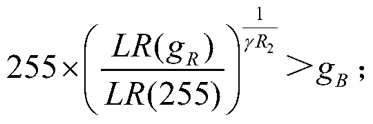
 若H∈(330°,345°],且C∈[C TL2,C TH2],则γ'R=γR 2,且
 若H∈(315°,330°],且C∈[C TL3,C TH3],则γ'R=γR 3,且
 若H∈(0°,15°],且C∈[C TL4,C TH4],则γ'R=γR 4,且
 若H∈(15°,30°],且C∈[C TL5,C TH5],则γ'R=γR 5,且
 若H∈(30°,45°],且C∈[C TL6,C TH6],则γ'R=γR 6,且
 所述H表示预设区域在LCH色域空间中的色相;所述C表示预设区域在LCH色域空间中的色相的饱和度,0≤C TLi<100,0<C THi≤100,C THi≥C TLi,i=1,2,3,4,5,6;所述γ'R表示调整后的第三子像素的伽马值,表示调整第三子像素的伽马值后第三子像素的等效灰阶,i=1,2,3,4,5。
- 如权利要求1所述的显示装置的驱动方法,其中,所述数据特征值包括:算数平均数、加数平均数、几何平均数、方差。
- 一种显示装置的驱动装置,其中,包括:获取模块,用于获取预设区域内每个像素单元对应的子像素在RGB色域空间中的色度坐标;数据特征值计算模块,用于根据所述子像素在RGB色域空间中的色度坐标,分别计算所述预设区域内每个子像素在RGB色域空间中的多个色度坐标的数据特征值;转换模块,用于将子像素在RGB色域空间中的色度坐标的数据特征值转换为LCH色域空间中的色度坐标;处理模块,用于若LCH色域空间中色度坐标中的饱和度和色相符合预设条件,则根据所述预设条件分别调整所述预设区域内子像素中第三子像素的伽马值,以使得调整后的第三子像素的伽马值大于调整前的第三子像素的伽马值,调整后的第三子像素的等效灰阶大于第一子像素的灰阶的数据特征值,且调整后的第三子像素的等效灰阶大于第二子像素的灰阶的数据特征值。
- 如权利要求7所述的显示装置的驱动装置,其中,还包括:第三子像素的亮度值获取模块,用于将调整前的第三子像素的伽马值作为第三子像素的初始伽马值,调整后的第三子像素的伽马值作为第三子像素的目标伽马值,并获取所述第三子像素的初始伽马值对应的亮度值和所述第三子像素的目标伽马值对应的亮度值;第三子像素的背光目标亮度信号值确定模块,用于根据所述第三子像素的初始伽马值对应的亮度值和所述第三子像素的目标伽马值对应的亮度值计算获得所述预设区域内对应背光子像素中第三子像素的背光目标亮度信号值。
- 如权利要求8所述的显示装置的驱动装置,其中,所述第三子像素的背光目标亮度信号值确定模块具体用于:
 所述A' N,MR表示预设区域内对应背光子像素中第三子像素的背光目标亮度信号值, A N,MR表示预设区域内对应背光子像素中第三子像素当前的背光亮度信号值;所述L N,MR表示所述预设区域内子像素中第三子像素的初始伽马值对应的亮度值,所述L' N,MR表示所述预设区域内子像素中第三子像素的目标伽马值对应的亮度值,所述N,M分别表示所述预设区域在划分的多个区域中的行数和列数。
 - 一种显示装置的驱动方法,其中,包括:获取预设区域内每个像素单元对应的子像素在RGB色域空间中的色度坐标;根据所述子像素在RGB色域空间中的色度坐标,分别计算所述预设区域内每个子像素在RGB色域空间中的多个色度坐标的数据特征值;将子像素在RGB色域空间中的色度坐标的数据特征值转换为LCH色域空间中的色度坐标;若LCH色域空间中色度坐标中的饱和度和色相符合预设条件,则根据所述预设条件调整所述预设区域内子像素中第三子像素的伽马值,以使得调整后的第三子像素的伽马值大于调整前的第三子像素的伽马值,调整后的第三子像素的等效灰阶大于第一子像素的灰阶的数据特征值,且调整后的第三子像素的等效灰阶大于第二子像素的灰阶的数据特征值;将调整前的第三子像素的伽马值作为第三子像素的初始伽马值,调整后的第三子像素的伽马值作为第三子像素的目标伽马值;获取所述第三子像素的初始伽马值对应的亮度值和所述第三子像素的目标伽马值对应的亮度值;根据所述第三子像素的初始伽马值对应的亮度值和所述第三子像素的目标伽马值对应的亮度值计算获得所述预设区域内对应背光子像素中第三子像素的背光目标亮度信号值;所述若LCH色域空间中色度坐标中的饱和度和色相符合预设条件,则根据所述预设条件调整所述预设区域内子像素中第三子像素的伽马值具体为:若H∈(345°,360°],且C∈[C TL1,C TH1],则γ'R=γR 1,且

 若H∈(330°,345°],且C∈[C TL2,C TH2],则γ'R=γR 2,且
 若H∈(315°,330°],且C∈[C TL3,C TH3],则γ'R=γR 3,且
 若H∈(0°,15°],且C∈[C TL4,C TH4],则γ'R=γR 4,且
 若H∈(15°,30°],且C∈[C TL5,C TH5],则γ'R=γR 5,且
 若H∈(30°,45°],且C∈[C TL6,C TH6],则γ'R=γR 6,且
 所述H表示预设区域在LCH色域空间中的色相;所述C表示预设区域在LCH色域空间中的色相的饱和度,0≤C TLi<100,0<C THi≤100,C THi≥C TLi,i=1,2,3,4,5,6;所述γ'R表示调整后的第三子像素的伽马值,表示调整第三子像素的伽马值后第三子像素的等效灰阶,i=1,2,3,4,5。
- 如权利要求10所述的显示装置的驱动方法,其中,所述根据所述第三子像素的初始伽马值对应的亮度值和所述第三子像素的目标伽马值对应的亮度值计算获得所述预设区域内对应背光子像素中第三子像素的背光目标亮度信号值具体为:

- 如权利要求11所述的显示装置的驱动方法,其中,所述A' N,MR表示预设区域内对应背光子像素中第三子像素的背光目标亮度信号值,A N,MR表示预设区域内对应背光子像素中第三子像素当前的背光亮度信号值;所述L N,MR表示所述预设区域内子像素中第三子像素的初始伽马值对应的亮度值,所述L' N,MR表示所述预设区域内子像素中第三子像素的目标伽 马值对应的亮度值,所述N,M分别表示所述预设区域在划分的多个区域中的行数和列数。
- 如权利要求12所述的显示装置的驱动方法,其中,所述获取所述第三子像素的初始伽马值对应的亮度值和所述第三子像素的目标伽马值对应的亮度值包括:所述第三子像素的初始伽马值对应的亮度值通过以下公式获取:
 所述第三子像素的目标伽马值对应的亮度值通过以下公式获取:
- 如权利要求13所述的显示装置的驱动方法,其中,所述L N,MR表示所述第三子像素的初始伽马值对应的亮度值,所述L' N,MR表示所述第三子像素的目标伽马值对应的亮度值;所述LR(255)表示第三子像素的灰阶为255时的亮度值,g R表示预设区域内每个像素单元中的第三子像素的灰阶的数据特征值;γR表示第三子像素的初始伽马值,所述γ'R表示第三子像素的目标伽马值。
- 如权利要求10所述的显示装置的驱动方法,其中,所述数据特征值包括:算数平均数、加数平均数、几何平均数、方差。
Applications Claiming Priority (2)
| Application Number | Priority Date | Filing Date | Title |
|---|---|---|---|
| CN201711381991.2 | 2017-12-20 | ||
| CN201711381991.2A CN108053797B (zh) | 2017-12-20 | 2017-12-20 | 一种显示装置的驱动方法及驱动装置 |
Publications (1)
| Publication Number | Publication Date |
|---|---|
| WO2019119794A1 true WO2019119794A1 (zh) | 2019-06-27 |
Family
ID=62130317
Family Applications (1)
| Application Number | Title | Priority Date | Filing Date |
|---|---|---|---|
| PCT/CN2018/096030 Ceased WO2019119794A1 (zh) | 2017-12-20 | 2018-07-17 | 一种显示装置的驱动方法及驱动装置 |
Country Status (2)
| Country | Link |
|---|---|
| CN (1) | CN108053797B (zh) |
| WO (1) | WO2019119794A1 (zh) |
Families Citing this family (11)
| Publication number | Priority date | Publication date | Assignee | Title |
|---|---|---|---|---|
| CN107863083B (zh) * | 2017-12-20 | 2019-12-13 | 惠科股份有限公司 | 一种显示装置的驱动方法及驱动装置 |
| CN107863084B (zh) * | 2017-12-20 | 2019-12-13 | 惠科股份有限公司 | 一种显示装置的驱动方法及驱动装置 |
| CN108053797B (zh) * | 2017-12-20 | 2019-12-13 | 惠科股份有限公司 | 一种显示装置的驱动方法及驱动装置 |
| CN107978289B (zh) * | 2017-12-20 | 2020-02-21 | 惠科股份有限公司 | 一种显示装置的驱动方法及驱动装置 |
| CN108765345B (zh) * | 2018-05-30 | 2020-10-27 | 深圳市华星光电技术有限公司 | 一种图像数据的调整方法 |
| CN109166162A (zh) * | 2018-10-08 | 2019-01-08 | 苏州仙峰网络科技股份有限公司 | 基于固定色相的2d变色方法 |
| CN111091785B (zh) * | 2018-10-24 | 2021-11-02 | 上海和辉光电股份有限公司 | 一种色偏补偿方法及装置 |
| CN109671399B (zh) * | 2018-12-11 | 2020-08-18 | 惠科股份有限公司 | 一种显示模组的驱动方法、驱动系统和显示装置 |
| WO2020211020A1 (en) * | 2019-04-17 | 2020-10-22 | Shenzhen Yunyinggu Technology Co., Ltd. | Method and system for determining grayscale mapping correlation in display panel |
| CN113327532B (zh) * | 2021-04-28 | 2022-10-11 | 华兴源创(成都)科技有限公司 | 一种显示面板的色偏补偿方法及装置、计算机设备及介质 |
| CN114801737B (zh) * | 2022-04-18 | 2022-11-04 | 黑龙江天有为电子股份有限公司 | 汽车仪表盘的调色方法、背光片的制作方法 |
Citations (9)
| Publication number | Priority date | Publication date | Assignee | Title |
|---|---|---|---|---|
| US20050140614A1 (en) * | 2003-12-29 | 2005-06-30 | Lg.Philips Lcd Co., Ltd. | Display device and method of driving the same |
| CN1770250A (zh) * | 2004-11-03 | 2006-05-10 | 中华映管股份有限公司 | 动态阶调补偿电路以及动态阶调补偿的方法 |
| CN102087841A (zh) * | 2009-12-08 | 2011-06-08 | 瑞萨电子株式会社 | 用于在显示设备中同时进行伽玛校正和对比度增强的装置 |
| CN104021767A (zh) * | 2013-03-01 | 2014-09-03 | 刘鸿达 | 伽码曲线调整方法与其伽码电压产生器和显示装置 |
| CN106981275A (zh) * | 2017-05-10 | 2017-07-25 | 惠科股份有限公司 | 显示面板像素驱动方法及显示装置 |
| CN107863083A (zh) * | 2017-12-20 | 2018-03-30 | 惠科股份有限公司 | 一种显示装置的驱动方法及驱动装置 |
| CN107863084A (zh) * | 2017-12-20 | 2018-03-30 | 惠科股份有限公司 | 一种显示装置的驱动方法及驱动装置 |
| CN107978289A (zh) * | 2017-12-20 | 2018-05-01 | 惠科股份有限公司 | 一种显示装置的驱动方法及驱动装置 |
| CN108053797A (zh) * | 2017-12-20 | 2018-05-18 | 惠科股份有限公司 | 一种显示装置的驱动方法及驱动装置 |
-
2017
- 2017-12-20 CN CN201711381991.2A patent/CN108053797B/zh active Active
-
2018
- 2018-07-17 WO PCT/CN2018/096030 patent/WO2019119794A1/zh not_active Ceased
Patent Citations (9)
| Publication number | Priority date | Publication date | Assignee | Title |
|---|---|---|---|---|
| US20050140614A1 (en) * | 2003-12-29 | 2005-06-30 | Lg.Philips Lcd Co., Ltd. | Display device and method of driving the same |
| CN1770250A (zh) * | 2004-11-03 | 2006-05-10 | 中华映管股份有限公司 | 动态阶调补偿电路以及动态阶调补偿的方法 |
| CN102087841A (zh) * | 2009-12-08 | 2011-06-08 | 瑞萨电子株式会社 | 用于在显示设备中同时进行伽玛校正和对比度增强的装置 |
| CN104021767A (zh) * | 2013-03-01 | 2014-09-03 | 刘鸿达 | 伽码曲线调整方法与其伽码电压产生器和显示装置 |
| CN106981275A (zh) * | 2017-05-10 | 2017-07-25 | 惠科股份有限公司 | 显示面板像素驱动方法及显示装置 |
| CN107863083A (zh) * | 2017-12-20 | 2018-03-30 | 惠科股份有限公司 | 一种显示装置的驱动方法及驱动装置 |
| CN107863084A (zh) * | 2017-12-20 | 2018-03-30 | 惠科股份有限公司 | 一种显示装置的驱动方法及驱动装置 |
| CN107978289A (zh) * | 2017-12-20 | 2018-05-01 | 惠科股份有限公司 | 一种显示装置的驱动方法及驱动装置 |
| CN108053797A (zh) * | 2017-12-20 | 2018-05-18 | 惠科股份有限公司 | 一种显示装置的驱动方法及驱动装置 |
Also Published As
| Publication number | Publication date |
|---|---|
| CN108053797A (zh) | 2018-05-18 |
| CN108053797B (zh) | 2019-12-13 |
Similar Documents
| Publication | Publication Date | Title |
|---|---|---|
| WO2019119794A1 (zh) | 一种显示装置的驱动方法及驱动装置 | |
| CN107978289B (zh) | 一种显示装置的驱动方法及驱动装置 | |
| WO2019119791A1 (zh) | 一种显示装置的驱动方法及驱动装置 | |
| CN107863084B (zh) | 一种显示装置的驱动方法及驱动装置 | |
| US11270657B2 (en) | Driving method, driving apparatus, display device and computer readable medium | |
| RU2660628C1 (ru) | Жидкокристаллическая панель и способ управления такой панелью | |
| US20200294455A1 (en) | Signal processing method and display device | |
| CN108122546B (zh) | 显示设备及其图像处理方法 | |
| WO2018214188A1 (zh) | 图像处理方法、图像处理装置及显示装置 | |
| US10825408B2 (en) | Display driving method, device and apparatus | |
| CN109285515B (zh) | 像素信号转换方法及装置 | |
| WO2019238071A1 (zh) | 色域转换方法、色域转换器、显示装置、图像信号转换方法、计算机设备和非暂时性存储介质 | |
| WO2020103242A1 (zh) | 阵列基板和显示面板 | |
| CN104361870B (zh) | 液晶面板及其像素单元设定方法 | |
| CN109166558B (zh) | 像素信号转换方法及装置 | |
| WO2020103244A1 (zh) | 像素驱动方法、像素驱动装置和计算机设备 | |
| WO2016197450A1 (zh) | 液晶面板及其驱动方法 | |
| WO2016070449A1 (zh) | 液晶面板及其驱动方法 | |
| WO2018040227A1 (zh) | 显示装置及其亮度调整方法 | |
| CN112884661A (zh) | 图像处理装置及其方法、显示装置和计算机可读存储介质 | |
| WO2019080446A1 (zh) | 显示装置的驱动方法及显示装置 | |
| US9311886B2 (en) | Display device including signal processing unit that converts an input signal for an input HSV color space, electronic apparatus including the display device, and drive method for the display device | |
| WO2019114480A1 (zh) | 多基色转换方法、显示面板的驱动方法及驱动装置、和显示设备 | |
| CN109377966B (zh) | 一种显示方法、系统及显示装置 | |
| US11315470B2 (en) | Display device and display method thereof |
Legal Events
| Date | Code | Title | Description |
|---|---|---|---|
| 121 | Ep: the epo has been informed by wipo that ep was designated in this application |
Ref document number: 18892796 Country of ref document: EP Kind code of ref document: A1 |
|
| NENP | Non-entry into the national phase |
Ref country code: DE |
|
| 32PN | Ep: public notification in the ep bulletin as address of the adressee cannot be established |
Free format text: NOTING OF LOSS OF RIGHTS PURSUANT TO RULE 112(1) EPC (EPO FORM 1205A DATED 02.10.2020) |
|
| 122 | Ep: pct application non-entry in european phase |
Ref document number: 18892796 Country of ref document: EP Kind code of ref document: A1 |