WO2019116560A1 - Vehicle floor carpet opening structure - Google Patents
Vehicle floor carpet opening structure Download PDFInfo
- Publication number
- WO2019116560A1 WO2019116560A1 PCT/JP2017/045177 JP2017045177W WO2019116560A1 WO 2019116560 A1 WO2019116560 A1 WO 2019116560A1 JP 2017045177 W JP2017045177 W JP 2017045177W WO 2019116560 A1 WO2019116560 A1 WO 2019116560A1
- Authority
- WO
- WIPO (PCT)
- Prior art keywords
- floor carpet
- opening
- vehicle
- lid
- power supply
- Prior art date
Links
Images

Classifications
-
- B—PERFORMING OPERATIONS; TRANSPORTING
- B60—VEHICLES IN GENERAL
- B60K—ARRANGEMENT OR MOUNTING OF PROPULSION UNITS OR OF TRANSMISSIONS IN VEHICLES; ARRANGEMENT OR MOUNTING OF PLURAL DIVERSE PRIME-MOVERS IN VEHICLES; AUXILIARY DRIVES FOR VEHICLES; INSTRUMENTATION OR DASHBOARDS FOR VEHICLES; ARRANGEMENTS IN CONNECTION WITH COOLING, AIR INTAKE, GAS EXHAUST OR FUEL SUPPLY OF PROPULSION UNITS IN VEHICLES
- B60K1/00—Arrangement or mounting of electrical propulsion units
- B60K1/04—Arrangement or mounting of electrical propulsion units of the electric storage means for propulsion
-
- B—PERFORMING OPERATIONS; TRANSPORTING
- B60—VEHICLES IN GENERAL
- B60N—SEATS SPECIALLY ADAPTED FOR VEHICLES; VEHICLE PASSENGER ACCOMMODATION NOT OTHERWISE PROVIDED FOR
- B60N3/00—Arrangements or adaptations of other passenger fittings, not otherwise provided for
- B60N3/04—Arrangements or adaptations of other passenger fittings, not otherwise provided for of floor mats or carpets
Definitions
- Patent Document 1 discloses a vehicle provided with a battery unit on a floor panel.
- the battery cover of the battery unit is provided with a plug access port for accessing the maintenance plug from the outside of the battery unit.
- the plug access port is covered by a removable access cover.
- An object of the present invention is to suppress the leakage of noise emitted from a power supply device into a vehicle compartment and to improve the quietness of the vehicle compartment.
- an opening and a lid portion capable of opening and closing the opening are formed in a portion covering the power supply device of the floor carpet laid to cover the power supply device. It is done.
- a cut is formed in the portion, and the cut defines at least a portion of the inner edge of the opening and at least a portion of the outer edge of the lid. The cut surface by the incision is inclined with respect to the thickness direction of the floor carpet near the incision.
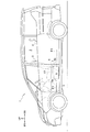
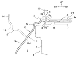
- FIG. 1 is a side view of a vehicle according to the embodiment.
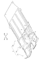
- FIG. 2 is a perspective view showing the structure of a floor carpet for a vehicle.
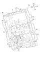
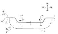
- FIG. 3 is a perspective view showing the configuration of the second floor carpet.
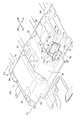
- FIG. 4 is a perspective view showing the opening formed in the bulging portion of the second floor carpet and the lid portion in the open position.
- FIG. 5 is a cross-sectional view taken along the line VV of FIG. 6 is a cross-sectional view taken along the line VI-VI in FIG.
- FIG. 7 is a plan view of the tongue portion and the fixing piece in a state in which the lid portion is in the closed position and the clip is not inserted into the first and second through holes.
- the front of the vehicle is indicated as FR, the rear of the vehicle as RR, the right in the vehicle width direction as RH, the left in the vehicle width direction as LH, and the upper side of the vehicle as UP.
- a front seat 3 is disposed in a front seat in a cabin 2.
- the front seat 3 is composed of a right seat, which is a driver's seat, and a left seat, which is a front passenger seat, arranged in the vehicle width direction. Both sheets are configured to be slidable in the front-rear direction on the seat rails, respectively.
- a rear seat 4 is disposed in the rear of the front seat 3, behind the second seat and in the third row. The rear seat 4 in the third row is not shown.
- a power supply device 6 for driving the vehicle is disposed below the front seat 3 and above the floor panel 5.
- the power supply device 6 is a high voltage device having a battery unit 7 for storing power supplied to the electric motor, and a control device (inverter, DC / DC converter, etc.) for controlling the power of the battery unit 7 to a predetermined voltage.
- noise high frequency noise
- the battery unit 7 has a substantially rectangular parallelepiped shape having a longitudinal direction in the vehicle width direction, and extends in the vehicle width direction from under the right side seat to below the left side seat.
- a front cross member 8 a extends along the vehicle width direction on the front side of the battery unit 7, and a rear cross member 8 b extends along the vehicle width direction on the rear side of the battery unit 7. There is.
- the front part of the battery unit 7 is fastened to the front cross member 8a, and the rear part of the battery unit 7 is fastened to the rear cross member 8b.
- a floor carpet F is laid on the floor panel 5.
- the floor carpet F includes a surface material layer constituting a carpet surface, a backing material layer as a backing material, a buffer material layer made of felt or foam, and the like, and has sound insulation and sound absorption performance in a wide frequency range.
- the floor carpet F is given a shape according to the uneven shape of the floor panel 5 and the power supply device 6 by press molding.
- the floor carpet F is composed of a first floor carpet F1, a second floor carpet F2, and a third floor carpet F3.
- the first floor carpet F1 is laid on the floor panel 5 in front of the power supply 6, the second floor carpet F2 is laid to cover the power supply 6 from above, and the third floor carpet F3 is laid on the power supply 6 It is laid on the rear floor panel 5.
- the second floor carpet F2 has a bulging portion 9 that accommodates the power supply device 6 so as to cover it.
- the bulging portion 9 has a shape in which a substantially rectangular area bulges upward in a plan view, and the top wall 9a, the front wall 9b, the back wall 9c, the left wall 9d, and the right And a wall 9e.
- a recessed groove 9f extending in the front-rear direction is formed at a position corresponding to the two seat rails on the center side in the vehicle width direction.
- the front wall 9b extends below the front edge of the top wall 9a
- the back wall 9c extends below the rear edge of the top wall 9a.
- the bulging portion 9 is provided with a concavo-convex shape corresponding to the shape of the power supply device 6, and a large number of convex bending portions p and concave bending portions v are formed.
- the convex bending portion p the second floor carpet F2 is locally bent with a curvature larger than that of the surrounding wall (including the flat wall) so as to be convex toward the vehicle interior, and the concave bending portion In v, it is bent so as to be concave toward the vehicle interior.
- the convex bending portion p forms a ridge line r extending linearly or curvilinearly along the surface of the bulging portion 9 on the vehicle interior side.
- a convex bending portion p is formed at a portion where the front wall portion 9b and the left wall portion 9d intersect.
- the ridge line r is substantially linear, and is inclined so as to be positioned forward as it goes downward.
- a convex bending portion p is formed at the intersection of the front wall portion 9b and the top wall portion 9a, and the ridge line r extends substantially linearly along the vehicle width direction.
- the convex bending part p is formed in the part which the front wall part 9b and the left side wall of the concave groove 9f of the left side cross
- the ridge line r is substantially linear, and is inclined so as to be positioned forward as it goes downward.
- a substantially C-shaped cut C opened downward as viewed from the vehicle interior side is inserted in the left front portion of the bulging portion 9.
- the incision C penetrates from the surface on the vehicle interior side of the bulging portion 9 to the back surface on the side opposite to the vehicle interior, and the opening C and the lid 12 are formed by the incision C.
- the opening 11 has a substantially rectangular shape, and in the inner edge of the opening 11, both ends of the upper side 11 a and the two left and right sides 11 b and 11 c are notches C Is defined by Further, the lid 12 has a substantially rectangular shape corresponding to the opening 11, and the upper side 12a and the two left and right sides 12b and 12c of the outer edge of the lid 12 are defined by the notch C. ing.
- the lid portion 12 is connected to the lower side 11d of the inner edge portion of the opening 11 at the lower side 12d of the outer edge portion, and is integrated with the second floor carpet F2.
- the inner edge of the opening 11 is a surface 11A on the vehicle interior side, a back surface 11B on the opposite side of the vehicle interior, an edge of the surface 11A and an edge of the back surface 11B And a side surface 11C connecting the Further, the outer edge portion of the lid portion 12 has a surface 12A on the vehicle interior side, a back surface 12B on the side opposite to the vehicle interior, and a side surface 12C connecting an edge of the surface 12A and an edge of the back surface 12B. .
- the side surface 11C of the inner edge portion and the side surface 12C of the outer edge portion are cut surfaces by the incision C.
- the side surfaces 11C and 12C are substantially parallel to each other, and are inclined with respect to the thickness direction T of the floor carpet F near the incision C. Therefore, when the incision C is viewed from the vehicle interior along the thickness direction T, the edge of the back surface 11B of the opening 11 is located closer to the center of the opening 11 than the edge of the surface 12A of the lid 12 . That is, when the lid 12 is in the closed position, the accommodation space S below the second floor carpet F2 is blocked by the surface 12A of the lid 12 and is difficult to see.
- the lid 12 has a flat plate-like main body 13 cut out from the front wall 9 b of the bulging part 9 and a flat plate-like tongue piece cut out from the top wall 9 a of the bulging part 9. And fourteen.
- the tongue portion 14 is bent so as to be convex toward the vehicle interior from the upper portion of the main body portion 13 and extends rearward.
- the tongue piece 14 is provided with two first through holes 15.
- the fixing piece 16 is provided with two second through holes 17.
- the fixed piece 16 is fastened to the tongue piece 14 by a clip 18 made of, for example, resin, which is a fastener that is inserted into both the through holes 15 and 17.
- the cut surfaces 11C and 12C by the cut C at the inner edge of the opening 11 and the outer edge of the lid 12 are in the thickness direction T of the second floor carpet F2 near the cut C. It is inclined against. Therefore, the width W of the cut surfaces 11C and 12C is larger than when the cut surfaces 11C and 12C are parallel to the thickness direction T, and the depth of the gap formed between the cut surfaces 11C and 12C is increased. As a result, leakage of noise generated by the power supply device 6 into the vehicle compartment is suppressed.
- the incision C is viewed in the thickness direction T of the floor carpet F, the accommodation space S below the second floor carpet F2 is difficult to see, so the appearance of the opening of the second floor carpet F2 is improved.
- the second floor carpet F2 (floor carpet F) has sound absorbing performance.
- the area of cut surface 11C, 12C is larger than the case where they are parallel to thickness direction T. For this reason, when the noise generated by the power supply device 6 passes from the accommodation space S side to the vehicle interior side from the accommodation space S side, the noise generated in the power supply device 6 flows from the cut surfaces 11C, 12C into the second floor carpet F2. It is easy to be absorbed by Thereby, it is possible to suppress the leakage of the noise generated by the power supply device 6 into the vehicle compartment.
- the tongue pieces 14 are offset in the extending direction. Therefore, the main body 13 can be drawn in the extension direction of the tongue piece 14 by inserting the clip 18 into both the through holes 15 and 17 and fastening the tongue piece 14 to the fixing piece 16. Thereby, the width of the gap formed between the inner edge of the opening 11 and the outer edge of the lid 12 can be further reduced, and the sound insulation of the opening of the second floor carpet F2 can be further improved.
- the pull-in force generated when fastening the tongue piece portion 14 to the fixing piece 16 is It can be made to act on the direction toward the opposite side of the vehicle cabin (inside of the accommodation space S) with respect to 13.
- the outer edge of the lid 12 can be drawn toward the inner edge of the opening 11 with a greater force, and the width of the gap formed between them can be further reduced to open the second floor carpet F2.
- the sound insulation of the part can be further improved.
- the lid 12 is connected to the lower side 11d of the opening 11 at the lower side 12d of the outer edge and is integral with the second floor carpet F2, the lid 12 can be integrally formed with the second floor carpet F2. The appearance of the opening of the second floor carpet F2 is improved.
- the incision C is formed along the ridge line r of the convex bending portion p, and a part of the convex bending portion p constitutes a part of the lid portion 12, a rib shape is formed on the peripheral portion of the lid portion 12 Is given to improve the rigidity of the lid 12.
- the outer edge of the lid 12 and a part of the inner edge of the opening 11 are defined by the incision C, the entire periphery of the outer edge and the inner edge is defined by the incision C.
- the portion 12 may be configured to be removable from the opening 11.
- the shape of the incision C when viewed from the vehicle interior side is not particularly limited, and may be a C-shape, a U-shape, an L-shape, a circle, an ellipse, a polygon or the like.
- the position at which the outer edge of the lid 12 and the inner edge of the opening 11 are integrally connected is not particularly limited.
- the right side 12 c of the outer edge of the lid 12 and the right side 11 c of the inner edge of the opening 11 are connected You may
- the said opening part structure can be utilized for the floor carpet installed so that the said power supply device might be covered in the vehicle which mounted the power supply device on the floor panel.
Landscapes
- Engineering & Computer Science (AREA)
- Transportation (AREA)
- Mechanical Engineering (AREA)
- Chemical & Material Sciences (AREA)
- Combustion & Propulsion (AREA)
- Passenger Equipment (AREA)
- Arrangement Or Mounting Of Propulsion Units For Vehicles (AREA)
Abstract
A vehicle floor carpet opening structure wherein the portion of a floor carpet (F2) covering a power supply (6) is formed with an opening (11) and a cap (12) capable of opening and closing the opening (11). At least a part of the inside edge of the opening (11) is defined by a cut (C) formed in said portion. At least a part of the outside edge of the cap (12) is defined by the cut (C). The cut faces (11C, 12C) formed by the cut (C) are inclined relative to the thickness direction (T) of the floor carpet (F2) around the cut (C).
Description
本発明は、車両用フロアカーペットの開口部構造に関する。
The present invention relates to an opening structure of a vehicle floor carpet.
特許文献1は、フロアパネル上にバッテリユニットを備える車両を開示している。バッテリユニットのバッテリカバーには、バッテリユニットの外部から保守点検用プラグにアクセスするためのプラグアクセス口が形成されている。プラグアクセス口は、着脱自在なアクセスカバーによって覆われている。
Patent Document 1 discloses a vehicle provided with a battery unit on a floor panel. The battery cover of the battery unit is provided with a plug access port for accessing the maintenance plug from the outside of the battery unit. The plug access port is covered by a removable access cover.
ところで、フロアパネル上に車両駆動用の電源装置を配置した車両では、当該電源装置を覆うフロアカーペットに、車室内側から電源装置にアクセスするための開口が設けられることがある。この場合、電源装置から発せられる騒音が上記開口とその蓋との間の隙間から車室内に漏れて、車室内の静粛性が低下する恐れがあった。
By the way, in a vehicle in which a power supply device for driving the vehicle is disposed on a floor panel, an opening for accessing the power supply device from the vehicle interior side may be provided in the floor carpet covering the power supply device. In this case, noise emitted from the power supply device may leak into the vehicle compartment from the gap between the opening and the lid thereof, which may reduce the quietness of the vehicle interior.
本発明の目的は、電源装置から発せられる騒音の車室内への漏れを抑制し、車室内の静粛性を向上させることにある。
An object of the present invention is to suppress the leakage of noise emitted from a power supply device into a vehicle compartment and to improve the quietness of the vehicle compartment.
本発明の一態様にかかる車両用フロアカーペットの開口部構造では、電源装置を覆うように敷設されたフロアカーペットの電源装置を覆う部分に、開口と、該開口を開閉可能な蓋部とが形成されている。前記部分には切込みが形成され、この切込みによって、開口の内縁部の少なくとも一部と蓋部の外縁部の少なくとも一部とが画成されている。切込みによる切断面は、当該切込み近傍のフロアカーペットの厚さ方向に対して傾斜している。
In the opening structure of the floor carpet for a vehicle according to one aspect of the present invention, an opening and a lid portion capable of opening and closing the opening are formed in a portion covering the power supply device of the floor carpet laid to cover the power supply device. It is done. A cut is formed in the portion, and the cut defines at least a portion of the inner edge of the opening and at least a portion of the outer edge of the lid. The cut surface by the incision is inclined with respect to the thickness direction of the floor carpet near the incision.
本発明によれば、電源装置から発せられる騒音の車室内への漏れを抑制し、車室内の静粛性を向上させることができる。
According to the present invention, it is possible to suppress the leakage of noise emitted from the power supply device into the vehicle compartment and to improve the quietness of the vehicle compartment.
以下、実施形態にかかる車両用フロアカーペットの開口部構造について、図1乃至図7を参照して説明する。なお、図面において、車両前方をFR、車両後方をRR、車幅方向右方をRH、車幅方向左方をLH、車両上方をUPとして示す。
Hereinafter, the opening part structure of the floor carpet for vehicles concerning embodiment is demonstrated with reference to FIG. 1 thru | or FIG. In the drawings, the front of the vehicle is indicated as FR, the rear of the vehicle as RR, the right in the vehicle width direction as RH, the left in the vehicle width direction as LH, and the upper side of the vehicle as UP.
図1に示すように、実施形態にかかる車両1では、車室2内の前席に前席シート3が配置されている。前席シート3は、互いに車幅方向に並んだ、運転席である右側シートと、助手席である左側シートとから構成される。両シートは、それぞれシートレール上を前後方向にスライド可能に構成されている。前席シート3の後方、2列目及び3列目の後席には、後席シート4が配置されている。3列目の後席シート4は、図示を省略している。
As shown in FIG. 1, in the vehicle 1 according to the embodiment, a front seat 3 is disposed in a front seat in a cabin 2. The front seat 3 is composed of a right seat, which is a driver's seat, and a left seat, which is a front passenger seat, arranged in the vehicle width direction. Both sheets are configured to be slidable in the front-rear direction on the seat rails, respectively. A rear seat 4 is disposed in the rear of the front seat 3, behind the second seat and in the third row. The rear seat 4 in the third row is not shown.
車両1では、前席シート3の下、且つ、フロアパネル5の上に、車両駆動用の電源装置6が配置されている。電源装置6は、電動モータに供給する電力を蓄えるためのバッテリユニット7や、バッテリユニット7の電力を所定電圧に制御する制御機器(インバータ、DC/DCコンバータなど)を有する高電圧機器である。電源装置6の動作時には、主に制御機器の動作に起因する騒音(高周波ノイズ)が発生する。
In the vehicle 1, a power supply device 6 for driving the vehicle is disposed below the front seat 3 and above the floor panel 5. The power supply device 6 is a high voltage device having a battery unit 7 for storing power supplied to the electric motor, and a control device (inverter, DC / DC converter, etc.) for controlling the power of the battery unit 7 to a predetermined voltage. During the operation of the power supply 6, noise (high frequency noise) is generated mainly due to the operation of the control device.
バッテリユニット7は、車幅方向に長手方向を有する略直方体形状を有しており、右側シートの下から左側シートの下まで車幅方向に延在している。バッテリユニット7の前側には、車幅方向に沿って前側クロスメンバ8aが延在しており、バッテリユニット7の後側には、車幅方向に沿って後側クロスメンバ8bが延在している。バッテリユニット7の前部は前側クロスメンバ8aに締結されており、バッテリユニット7の後部は後側クロスメンバ8bに締結されている。
The battery unit 7 has a substantially rectangular parallelepiped shape having a longitudinal direction in the vehicle width direction, and extends in the vehicle width direction from under the right side seat to below the left side seat. A front cross member 8 a extends along the vehicle width direction on the front side of the battery unit 7, and a rear cross member 8 b extends along the vehicle width direction on the rear side of the battery unit 7. There is. The front part of the battery unit 7 is fastened to the front cross member 8a, and the rear part of the battery unit 7 is fastened to the rear cross member 8b.
図1及び図2に示すように、フロアパネル5の上には、フロアカーペットFが敷設されている。フロアカーペットFは、カーペット表皮を構成する表皮材層、裏打ち材としてのバッキング材層、フェルトや発泡体からなる緩衝材層などを備え、広い周波数域において遮音・吸音性能を有している。フロアカーペットFは、プレス成形によりフロアパネル5や電源装置6の凹凸形状に合わせた形状が付与されている。
As shown in FIGS. 1 and 2, a floor carpet F is laid on the floor panel 5. The floor carpet F includes a surface material layer constituting a carpet surface, a backing material layer as a backing material, a buffer material layer made of felt or foam, and the like, and has sound insulation and sound absorption performance in a wide frequency range. The floor carpet F is given a shape according to the uneven shape of the floor panel 5 and the power supply device 6 by press molding.
フロアカーペットFは、第1フロアカーペットF1と、第2フロアカーペットF2と、第3フロアカーペットF3とから構成されている。第1フロアカーペットF1は、電源装置6より前方のフロアパネル5に敷設され、第2フロアカーペットF2は、電源装置6を上方から覆うように敷設され、第3フロアカーペットF3は、電源装置6より後方のフロアパネル5に敷設されている。
The floor carpet F is composed of a first floor carpet F1, a second floor carpet F2, and a third floor carpet F3. The first floor carpet F1 is laid on the floor panel 5 in front of the power supply 6, the second floor carpet F2 is laid to cover the power supply 6 from above, and the third floor carpet F3 is laid on the power supply 6 It is laid on the rear floor panel 5.
図1乃至図3に示すように、第2フロアカーペットF2は、電源装置6を覆うようにして収容する膨出部9を有している。膨出部9は、平面視において略矩形状の領域が上方に膨出した形状を有し、天壁部9aと、前壁部9bと、後壁部9cと、左壁部9dと、右壁部9eとを備えている。天壁部9aには、車幅方向中央側の2本のシートレールに対応する位置に、前後方向に延びる凹溝9fが形成されている。前壁部9bは、天壁部9aの前側端縁より下方に延びており、後壁部9cは、天壁部9aの後側端縁より下方に延びている。左壁部9dは、天壁部9aの左側端縁より下方に延びており、右壁部9eは、天壁部9aの右側端縁より下方に延びている。膨出部9とフロアパネル5との間には、収容空間Sが画成されており、その収容空間S内に電源装置6が収容されている。膨出部9の周囲には、フロアパネル5及び前後のクロスメンバ8a,8bの上面に沿って延びる外周縁部10が設けられている。
As shown in FIG. 1 to FIG. 3, the second floor carpet F2 has a bulging portion 9 that accommodates the power supply device 6 so as to cover it. The bulging portion 9 has a shape in which a substantially rectangular area bulges upward in a plan view, and the top wall 9a, the front wall 9b, the back wall 9c, the left wall 9d, and the right And a wall 9e. In the top wall portion 9a, a recessed groove 9f extending in the front-rear direction is formed at a position corresponding to the two seat rails on the center side in the vehicle width direction. The front wall 9b extends below the front edge of the top wall 9a, and the back wall 9c extends below the rear edge of the top wall 9a. The left wall 9 d extends downward from the left edge of the top wall 9 a, and the right wall 9 e extends downward from the right edge of the top wall 9 a. An accommodation space S is defined between the bulging portion 9 and the floor panel 5, and the power supply device 6 is accommodated in the accommodation space S. An outer peripheral edge portion 10 extending along the upper surfaces of the floor panel 5 and the front and rear cross members 8 a and 8 b is provided around the bulging portion 9.
膨出部9には、電源装置6の形状に対応した凹凸形状が付与されており、多くの凸状屈曲部p及び凹状屈曲部vが形成されている。凸状屈曲部pでは、第2フロアカーペットF2が、局所的に周囲の壁部(平面壁を含む)よりも大きな曲率で、車室内側に凸となるように屈曲しており、凹状屈曲部vでは、車室内側に凹となるように屈曲している。凸状屈曲部pは、膨出部9の車室内側の表面に沿って直線状または曲線状に延びる稜線rを形成している。
The bulging portion 9 is provided with a concavo-convex shape corresponding to the shape of the power supply device 6, and a large number of convex bending portions p and concave bending portions v are formed. In the convex bending portion p, the second floor carpet F2 is locally bent with a curvature larger than that of the surrounding wall (including the flat wall) so as to be convex toward the vehicle interior, and the concave bending portion In v, it is bent so as to be concave toward the vehicle interior. The convex bending portion p forms a ridge line r extending linearly or curvilinearly along the surface of the bulging portion 9 on the vehicle interior side.
例えば、膨出部9の左前部では、前壁部9bと左壁部9dとが交差する部分に凸状屈曲部pが形成されている。その稜線rは、略直線状であり、下方に向かうほど前方に位置するように傾斜している。また、前壁部9bと天壁部9aとが交差する部分に凸状屈曲部pが形成されており、その稜線rは、車幅方向に沿って略直線状に延びている。さらに、前壁部9bと左側の凹溝9fの左側壁とが交差する部分に凸状屈曲部pが形成されている。その稜線rは、略直線状であり、下方に向かうほど前方に位置するように傾斜している。
For example, in the left front portion of the bulging portion 9, a convex bending portion p is formed at a portion where the front wall portion 9b and the left wall portion 9d intersect. The ridge line r is substantially linear, and is inclined so as to be positioned forward as it goes downward. In addition, a convex bending portion p is formed at the intersection of the front wall portion 9b and the top wall portion 9a, and the ridge line r extends substantially linearly along the vehicle width direction. Furthermore, the convex bending part p is formed in the part which the front wall part 9b and the left side wall of the concave groove 9f of the left side cross | intersect. The ridge line r is substantially linear, and is inclined so as to be positioned forward as it goes downward.
図3及び図5に示すように、膨出部9の左前部には、車室内側からみて下方に開いた略コ字状の切込みCが入れられている。切込みCは、膨出部9の車室内側の表面から反車室内側の裏面まで貫通しており、この切込みCにより、開口11と蓋部12とが形成されている。
As shown in FIGS. 3 and 5, a substantially C-shaped cut C opened downward as viewed from the vehicle interior side is inserted in the left front portion of the bulging portion 9. The incision C penetrates from the surface on the vehicle interior side of the bulging portion 9 to the back surface on the side opposite to the vehicle interior, and the opening C and the lid 12 are formed by the incision C.
図3及び図4に示すように、開口11は、略矩形状の形状を有しており、開口11の内縁部のうち、上辺11aの両端部及び左右の二辺11b,11cは、切込みCにより画成されている。また、蓋部12は、開口11に対応する略矩形状の形状を有しており、蓋部12の外縁部のうち、上辺12a及び左右の二辺12b,12cは、切込みCにより画成されている。蓋部12は、その外縁部の下辺12dにおいて開口11の内縁部の下辺11dに接続され、第2フロアカーペットF2と一体になっている。蓋部12は、第2フロアカーペットF2を外縁部の下辺12dに相当する位置で折り曲げることより、図6に一点鎖線で示す開位置と、同図において実線で示す閉位置との間を前後に回動することができ、これにより蓋部12は、開口11を開閉可能である。開口11は、蓋部12が開位置にあるときに、車室内側から電源装置6へのアクセスを許容する大きさを有しており、例えばバッテリユニット7のシャットダウンスイッチなどを車室内側から操作することが可能になっている。
As shown in FIGS. 3 and 4, the opening 11 has a substantially rectangular shape, and in the inner edge of the opening 11, both ends of the upper side 11 a and the two left and right sides 11 b and 11 c are notches C Is defined by Further, the lid 12 has a substantially rectangular shape corresponding to the opening 11, and the upper side 12a and the two left and right sides 12b and 12c of the outer edge of the lid 12 are defined by the notch C. ing. The lid portion 12 is connected to the lower side 11d of the inner edge portion of the opening 11 at the lower side 12d of the outer edge portion, and is integrated with the second floor carpet F2. The lid 12 bends the second floor carpet F2 at a position corresponding to the lower side 12d of the outer edge, thereby providing back and forth between the open position shown by an alternate long and short dash line in FIG. 6 and the closed position shown by a solid line in FIG. It can be pivoted so that the lid 12 can open and close the opening 11. The opening 11 has a size that allows access to the power supply device 6 from the vehicle compartment side when the lid 12 is in the open position. For example, the shutdown switch of the battery unit 7 is operated from the vehicle compartment side It is possible to
また、図3に示すように、切込みCの一部は、屈曲部の稜線rに沿って形成されている。切込みCが稜線rに沿って形成された部分では、図5に示すように、切込みCの横断面において、凸状屈曲部pの一部が蓋部12の外縁部を構成している。なお、切込みCを、同断面において凸状屈曲部pよりも外側に形成し、凸状屈曲部pの全部が蓋部12の外縁部を構成するようにしてもよい。
Further, as shown in FIG. 3, a part of the incision C is formed along the ridge line r of the bent portion. At a portion where the incision C is formed along the ridge line r, as shown in FIG. 5, in the cross section of the incision C, a part of the convex bending portion p constitutes the outer edge of the lid 12. The incision C may be formed outside the convex bending portion p in the same cross section, and the entire convex bending portion p may form the outer edge portion of the lid 12.
図5に示すように、切込みCの横断面では、開口11の内縁部は、車室内側の表面11Aと、反車室内側の裏面11Bと、表面11Aの端縁と裏面11Bの端縁とを接続する側面11Cとを有している。また、蓋部12の外縁部は、車室内側の表面12Aと、反車室内側の裏面12Bと、表面12Aの端縁と裏面12Bの端縁とを接続する側面12Cとを有している。このうち内縁部の側面11C及び外縁部の側面12Cが、切込みCによる切断面である。
As shown in FIG. 5, in the cross section of the incision C, the inner edge of the opening 11 is a surface 11A on the vehicle interior side, a back surface 11B on the opposite side of the vehicle interior, an edge of the surface 11A and an edge of the back surface 11B And a side surface 11C connecting the Further, the outer edge portion of the lid portion 12 has a surface 12A on the vehicle interior side, a back surface 12B on the side opposite to the vehicle interior, and a side surface 12C connecting an edge of the surface 12A and an edge of the back surface 12B. . Among these, the side surface 11C of the inner edge portion and the side surface 12C of the outer edge portion are cut surfaces by the incision C.
側面11C,12Cは、互いに略平行であり、且つ、切込みC近傍のフロアカーペットFの厚さ方向Tに対して傾斜している。従って、切込みCを厚さ方向Tに沿って車室内側からみたとき、開口11の裏面11Bの端縁は、蓋部12の表面12Aの端縁よりも開口11の中心寄りに位置している。すなわち、蓋部12が閉位置にあるとき、第2フロアカーペットF2の下の収容空間Sが、蓋部12の表面12Aに遮られて見えにくくなっている。
The side surfaces 11C and 12C are substantially parallel to each other, and are inclined with respect to the thickness direction T of the floor carpet F near the incision C. Therefore, when the incision C is viewed from the vehicle interior along the thickness direction T, the edge of the back surface 11B of the opening 11 is located closer to the center of the opening 11 than the edge of the surface 12A of the lid 12 . That is, when the lid 12 is in the closed position, the accommodation space S below the second floor carpet F2 is blocked by the surface 12A of the lid 12 and is difficult to see.
図4に示すように、蓋部12は、膨出部9の前壁部9bから切り出した平板状の本体部13と、膨出部9の天壁部9aから切り出した平板状の舌片部14とを備えている。図6に示すように、舌片部14は、本体部13の上部から車室内側に凸となるように屈曲して後方へ延出している。舌片部14には、2つの第1貫通孔15が設けられている。
As shown in FIG. 4, the lid 12 has a flat plate-like main body 13 cut out from the front wall 9 b of the bulging part 9 and a flat plate-like tongue piece cut out from the top wall 9 a of the bulging part 9. And fourteen. As shown in FIG. 6, the tongue portion 14 is bent so as to be convex toward the vehicle interior from the upper portion of the main body portion 13 and extends rearward. The tongue piece 14 is provided with two first through holes 15.
開口11の内縁部のうち、舌片部14に対応する部分には、例えば樹脂製の固定片16が取り付けられている。固定片16には、2つの第2貫通孔17が設けられている。固定片16は、両貫通孔15,17に挿通される締結具である例えば樹脂製のクリップ18により、舌片部14に締結される。
A fixing piece 16 made of resin, for example, is attached to a portion corresponding to the tongue piece 14 in the inner edge portion of the opening 11. The fixing piece 16 is provided with two second through holes 17. The fixed piece 16 is fastened to the tongue piece 14 by a clip 18 made of, for example, resin, which is a fastener that is inserted into both the through holes 15 and 17.
図6及び図7に示すように、蓋部12が閉位置にあって開口11を閉じており、且つ、クリップ18が両貫通孔15,17に挿通されていない状態において、第2貫通孔17は、第1貫通孔15に対して舌片部14の延出方向にオフセットしている。クリップ18の挿通部の外径D1は、両貫通孔15,17の内径D2より小さいが、上記オフセット状態にある両貫通孔15,17によって形成される貫通孔の最短径D3よりも大きい。従って、クリップ18を両貫通孔15,17に挿通して、舌片部14を固定片16に締結したときには、図6に矢印で示す方向の引張力が、舌片部14に対して付与される。
As shown in FIGS. 6 and 7, the second through hole 17 is in a state in which the lid 12 is in the closed position and the opening 11 is closed, and the clip 18 is not inserted into both through holes 15 and 17. Is offset from the first through hole 15 in the extension direction of the tongue portion 14. The outer diameter D1 of the insertion portion of the clip 18 is smaller than the inner diameter D2 of both the through holes 15 and 17 but larger than the shortest diameter D3 of the through hole formed by the two through holes 15 and 17 in the offset state. Therefore, when the clip 18 is inserted into both through holes 15 and 17 and the tongue piece 14 is fastened to the fixing piece 16, a tensile force in the direction shown by the arrow in FIG. 6 is applied to the tongue piece 14. Ru.
以下、本実施形態にかかる作用効果について説明する。
Hereinafter, the operation and effect according to the present embodiment will be described.
本実施形態では、図5に示すように、開口11の内縁部及び蓋部12の外縁部における切込みCによる切断面11C,12Cが、切込みC近傍の第2フロアカーペットF2の厚さ方向Tに対して傾斜している。このため、切断面11C,12Cが厚さ方向Tに平行な場合よりも、切断面11C,12Cの幅Wが大きくなり、切断面11C,12C間に形成される隙間の奥行きが増す。これにより、電源装置6で発生した騒音の車室内への漏れが抑制される。また、切込みCをフロアカーペットFの厚さ方向Tから見たときに、第2フロアカーペットF2の下の収容空間Sが見えにくくなるため、第2フロアカーペットF2の開口部の見栄えが向上する。
In the present embodiment, as shown in FIG. 5, the cut surfaces 11C and 12C by the cut C at the inner edge of the opening 11 and the outer edge of the lid 12 are in the thickness direction T of the second floor carpet F2 near the cut C. It is inclined against. Therefore, the width W of the cut surfaces 11C and 12C is larger than when the cut surfaces 11C and 12C are parallel to the thickness direction T, and the depth of the gap formed between the cut surfaces 11C and 12C is increased. As a result, leakage of noise generated by the power supply device 6 into the vehicle compartment is suppressed. In addition, when the incision C is viewed in the thickness direction T of the floor carpet F, the accommodation space S below the second floor carpet F2 is difficult to see, so the appearance of the opening of the second floor carpet F2 is improved.
また、第2フロアカーペットF2(フロアカーペットF)は、吸音性能を有している。そして、上記の通り、切断面11C,12Cが厚さ方向Tに対して傾斜しているため、それらが厚さ方向Tに平行な場合よりも、切断面11C,12Cの面積が大きい。このため、電源装置6で発生した騒音が、切断面11C,12C間に形成された隙間を収容空間S側から車室内側へ通過する際に、切断面11C,12Cから第2フロアカーペットF2内に吸収されやすくなる。これにより、電源装置6で発生した騒音の車室内への漏れを抑制することができる。
Also, the second floor carpet F2 (floor carpet F) has sound absorbing performance. And as above-mentioned, since cut surface 11C, 12C inclines with respect to thickness direction T, the area of cut surface 11C, 12C is larger than the case where they are parallel to thickness direction T. For this reason, when the noise generated by the power supply device 6 passes from the accommodation space S side to the vehicle interior side from the accommodation space S side, the noise generated in the power supply device 6 flows from the cut surfaces 11C, 12C into the second floor carpet F2. It is easy to be absorbed by Thereby, it is possible to suppress the leakage of the noise generated by the power supply device 6 into the vehicle compartment.
さらに、蓋部12が開口11を閉じた状態で、且つ、クリップ18が第1及び第2貫通孔15,17に挿通されていない状態において、第2貫通孔17は、第1貫通孔15に対して舌片部14の延出方向にオフセットしている。このため、両貫通孔15,17にクリップ18を挿通し、舌片部14を固定片16に締結することで、本体部13を舌片部14の延出方向に引き込むことができる。これにより、開口11の内縁部と蓋部12の外縁部との間に形成される隙間の幅をより小さくして、第2フロアカーペットF2の開口部の遮音性をさらに向上させることができる。
Furthermore, in a state in which the lid 12 closes the opening 11 and in a state in which the clip 18 is not inserted into the first and second through holes 15 and 17, the second through hole 17 is inserted into the first through hole 15. On the other hand, the tongue pieces 14 are offset in the extending direction. Therefore, the main body 13 can be drawn in the extension direction of the tongue piece 14 by inserting the clip 18 into both the through holes 15 and 17 and fastening the tongue piece 14 to the fixing piece 16. Thereby, the width of the gap formed between the inner edge of the opening 11 and the outer edge of the lid 12 can be further reduced, and the sound insulation of the opening of the second floor carpet F2 can be further improved.
また、舌片部14は、本体部13から車室内側に凸となるように屈曲して延出しているため、舌片部14を固定片16に締結する際に生じる引き込み力を、本体部13に対して、より反車室内側(収容空間S内側)へ向かう方向に作用させることができる。これにより、蓋部12の外縁部を開口11の内縁部に向けてより大きな力で引き寄せることができ、それらの間に形成される隙間の幅をさらに小さくして、第2フロアカーペットF2の開口部の遮音性を一層向上させることができる。
Further, since the tongue piece portion 14 is bent and extended so as to be convex from the main body portion 13 to the vehicle interior side, the pull-in force generated when fastening the tongue piece portion 14 to the fixing piece 16 is It can be made to act on the direction toward the opposite side of the vehicle cabin (inside of the accommodation space S) with respect to 13. As a result, the outer edge of the lid 12 can be drawn toward the inner edge of the opening 11 with a greater force, and the width of the gap formed between them can be further reduced to open the second floor carpet F2. The sound insulation of the part can be further improved.
また、蓋部12は、外縁部の下辺12dにおいて開口11の下辺11dに接続され、第2フロアカーペットF2と一体になっているので、蓋部12を第2フロアカーペットF2と一体に成形でき、第2フロアカーペットF2の開口部の外観が向上する。
Further, since the lid 12 is connected to the lower side 11d of the opening 11 at the lower side 12d of the outer edge and is integral with the second floor carpet F2, the lid 12 can be integrally formed with the second floor carpet F2. The appearance of the opening of the second floor carpet F2 is improved.
さらに、切込みCが凸状屈曲部pの稜線rに沿って形成され、凸状屈曲部pの一部が蓋部12の一部を構成しているため、蓋部12の周縁部にリブ状の形状が付与されて、蓋部12の剛性が向上する。
Furthermore, since the incision C is formed along the ridge line r of the convex bending portion p, and a part of the convex bending portion p constitutes a part of the lid portion 12, a rib shape is formed on the peripheral portion of the lid portion 12 Is given to improve the rigidity of the lid 12.
上記実施形態は発明の理解を容易にするために記載された単なる例示に過ぎない。発明の技術的範囲は、上記実施形態で開示した具体的な技術事項に限らず、そこから容易に導きうる様々な変形、変更、代替技術なども含むものである。
The above embodiments are merely exemplary described to facilitate the understanding of the invention. The technical scope of the invention is not limited to the specific technical matters disclosed in the above embodiment, but also includes various modifications, alterations, and alternative technologies that can be easily derived therefrom.
例えば、上記実施形態では、蓋部12の外縁部及び開口11の内縁部の一部が切込みCにより画成されていたが、外縁部及び内縁部の全周を切込みCにより画成し、蓋部12を開口11から着脱自在に構成してもよい。また、車室内側からみたときの切込みCの形状は、特に限定されず、C字状、U字状、L字状、円状、楕円状、多角形状などであってもよい。蓋部12の外縁部と開口11の内縁部とが一体に接続される位置も、特に限定されず、例えば、蓋部12の外縁部の右辺12cと開口11の内縁部の右辺11cとを接続してもよい。
For example, in the above embodiment, although the outer edge of the lid 12 and a part of the inner edge of the opening 11 are defined by the incision C, the entire periphery of the outer edge and the inner edge is defined by the incision C. The portion 12 may be configured to be removable from the opening 11. Further, the shape of the incision C when viewed from the vehicle interior side is not particularly limited, and may be a C-shape, a U-shape, an L-shape, a circle, an ellipse, a polygon or the like. The position at which the outer edge of the lid 12 and the inner edge of the opening 11 are integrally connected is not particularly limited. For example, the right side 12 c of the outer edge of the lid 12 and the right side 11 c of the inner edge of the opening 11 are connected You may
上記開口部構造は、フロアパネル上に電源装置を搭載した車両において当該電源装置を覆うように敷設されたフロアカーペットに利用することができる。
The said opening part structure can be utilized for the floor carpet installed so that the said power supply device might be covered in the vehicle which mounted the power supply device on the floor panel.
2 車室
5 フロアパネル
6 電源装置
F2 第2フロアカーペット(フロアカーペット)
9 膨出部(電源装置を覆う部分)
C 切込み
T 厚さ方向
11 開口
11C 側面(切断面)
12 蓋部
12C 側面(切断面)
13 本体部
14 舌片部
15 第1貫通孔
16 固定片
17 第2貫通孔
18 クリップ(締結具)
p 凸状屈曲部(屈曲部)
r 稜線 2cabin 5 floor panel 6 power supply F2 second floor carpet (floor carpet)
9 bulging part (part that covers the power supply)
C notchedT thickness direction 11 opening 11C side surface (cut surface)
12lid 12C side (cut surface)
13body part 14 tongue piece part 15 first through hole 16 fixed piece 17 second through hole 18 clip (fastener)
p convex bend (bent)
r ridge line
5 フロアパネル
6 電源装置
F2 第2フロアカーペット(フロアカーペット)
9 膨出部(電源装置を覆う部分)
C 切込み
T 厚さ方向
11 開口
11C 側面(切断面)
12 蓋部
12C 側面(切断面)
13 本体部
14 舌片部
15 第1貫通孔
16 固定片
17 第2貫通孔
18 クリップ(締結具)
p 凸状屈曲部(屈曲部)
r 稜線 2
9 bulging part (part that covers the power supply)
C notched
12
13
p convex bend (bent)
r ridge line
Claims (5)
- フロアパネルの上に配置された車両駆動用の電源装置と、
前記電源装置を覆うように前記フロアパネルに敷設されたフロアカーペットと、
を備え、
前記フロアカーペットの前記電源装置を覆う部分には、
当該部分に形成された切込みにより内縁部の少なくとも一部が画成された開口と、
前記切込みにより外縁部の少なくとも一部が画成された、前記開口を開閉可能な蓋部と、
が形成されており、
前記内縁部及び前記外縁部における前記切込みによる切断面が、当該切込み近傍の前記フロアカーペットの厚さ方向に対して傾斜していることを特徴とする車両用フロアカーペットの開口部構造。 A power supply for driving a vehicle disposed above the floor panel;
A floor carpet laid on the floor panel to cover the power supply;
Equipped with
The portion covering the power supply of the floor carpet is
An opening defined by at least a portion of the inner edge by a cut formed in the portion;
A lid portion capable of opening and closing the opening, wherein at least a part of the outer edge portion is defined by the incision;
Is formed,
An opening structure of a floor carpet for a vehicle, characterized in that a cut surface by the cut at the inner edge and the outer edge is inclined with respect to a thickness direction of the floor carpet near the cut. - 前記蓋部は、平板状の本体部と、前記本体部から延出し、且つ、第1貫通孔を有する舌片部と、を備え、
前記開口の内縁部には、第2貫通孔を有し、且つ、前記第1及び第2貫通孔に挿通される締結具により前記舌片部に締結される固定片が設けられ、
前記蓋部が前記開口を閉じた状態で、且つ、前記締結具が前記第1及び第2貫通孔に挿通されていない状態において、前記第2貫通孔は、前記第1貫通孔に対して前記舌片部の延出方向にオフセットしていることを特徴とする請求項1に記載の車両用フロアカーペットの開口部構造。 The lid portion includes a flat plate-like main body portion, and a tongue portion portion extending from the main body portion and having a first through hole.
The inner edge portion of the opening is provided with a fixing piece that has a second through hole and that is fastened to the tongue piece by a fastener that is inserted into the first and second through holes.
In the state where the lid portion closes the opening, and in the state where the fastener is not inserted into the first and second through holes, the second through hole corresponds to the first through hole. The opening structure of a floor carpet for a vehicle according to claim 1, which is offset in the extending direction of the tongue portion. - 前記舌片部は、前記本体部から車室内側に凸となるように屈曲して延出することを特徴とする請求項2に記載の車両用フロアカーペットの開口部構造。 The opening structure of a floor carpet for a vehicle according to claim 2, wherein the tongue portion is bent and extended so as to be convex toward the vehicle interior side from the main body portion.
- 前記蓋部は、前記外縁部の一部において前記開口の内縁部の一部に接続され、前記フロアカーペットと一体になっていることを特徴とする請求項1乃至3のいずれか一項に記載の車両用フロアカーペットの開口部構造。 The said cover part is connected to a part of inner edge part of the said opening in a part of said outer edge part, and is integral with the said floor carpet, It is described in any one of the Claims 1 thru | or 3 characterized by the above-mentioned. Of car floor carpet opening structure.
- 前記フロアカーペットの前記電源装置を覆う部分には、車室内側に凸となるように屈曲して前記部分の車室内側の面に稜線を形成している屈曲部が形成されており、
前記切込みは、前記稜線に沿って形成されており、
前記屈曲部の少なくとも一部が前記蓋部の一部を構成していることを特徴とする請求項1乃至4のいずれか一項に記載の車両用フロアカーペットの開口部構造。 In a portion covering the power supply device of the floor carpet, a bent portion is formed so as to be convex toward the vehicle interior and a ridge is formed on a surface of the portion on the vehicle interior side,
The incisions are formed along the ridges,
The opening structure of a floor carpet for a vehicle according to any one of claims 1 to 4, wherein at least a part of the bent part constitutes a part of the lid.
Priority Applications (2)
| Application Number | Priority Date | Filing Date | Title |
|---|---|---|---|
| PCT/JP2017/045177 WO2019116560A1 (en) | 2017-12-15 | 2017-12-15 | Vehicle floor carpet opening structure |
| JP2019558850A JP6935820B2 (en) | 2017-12-15 | 2017-12-15 | Vehicle floor carpet opening structure |
Applications Claiming Priority (1)
| Application Number | Priority Date | Filing Date | Title |
|---|---|---|---|
| PCT/JP2017/045177 WO2019116560A1 (en) | 2017-12-15 | 2017-12-15 | Vehicle floor carpet opening structure |
Publications (1)
| Publication Number | Publication Date |
|---|---|
| WO2019116560A1 true WO2019116560A1 (en) | 2019-06-20 |
Family
ID=66820147
Family Applications (1)
| Application Number | Title | Priority Date | Filing Date |
|---|---|---|---|
| PCT/JP2017/045177 WO2019116560A1 (en) | 2017-12-15 | 2017-12-15 | Vehicle floor carpet opening structure |
Country Status (2)
| Country | Link |
|---|---|
| JP (1) | JP6935820B2 (en) |
| WO (1) | WO2019116560A1 (en) |
Cited By (6)
| Publication number | Priority date | Publication date | Assignee | Title |
|---|---|---|---|---|
| US11397893B2 (en) | 2019-09-04 | 2022-07-26 | Google Llc | Neural network formation configuration feedback for wireless communications |
| US11663472B2 (en) | 2020-06-29 | 2023-05-30 | Google Llc | Deep neural network processing for a user equipment-coordination set |
| US11689940B2 (en) | 2019-12-13 | 2023-06-27 | Google Llc | Machine-learning architectures for simultaneous connection to multiple carriers |
| US11886991B2 (en) | 2019-11-27 | 2024-01-30 | Google Llc | Machine-learning architectures for broadcast and multicast communications |
| US11928587B2 (en) | 2019-08-14 | 2024-03-12 | Google Llc | Base station-user equipment messaging regarding deep neural networks |
| US12001943B2 (en) | 2019-08-14 | 2024-06-04 | Google Llc | Communicating a neural network formation configuration |
Citations (10)
| Publication number | Priority date | Publication date | Assignee | Title |
|---|---|---|---|---|
| JPS6344263Y2 (en) * | 1982-07-06 | 1988-11-17 | ||
| JPH0742712U (en) * | 1993-12-31 | 1995-08-11 | 株式会社ホンダアクセス | Mat with storage |
| JP2000108752A (en) * | 1998-10-02 | 2000-04-18 | Takehiro:Kk | Luggage mat for vehicle |
| JP2002166728A (en) * | 2000-11-30 | 2002-06-11 | Toyota Auto Body Co Ltd | Cooling structure of high voltage battery |
| WO2008134911A2 (en) * | 2007-05-08 | 2008-11-13 | Rieter Technologies Ag | Carpet arrangement for an automobile and insert mat |
| US20080292827A1 (en) * | 2007-05-23 | 2008-11-27 | Jae Yong Lee | Car mat module |
| JP2009078577A (en) * | 2007-09-25 | 2009-04-16 | Honda Motor Co Ltd | Method of forming sheet for vehicle and sheet for vehicle |
| JP2013103690A (en) * | 2011-11-16 | 2013-05-30 | Toyota Motor Corp | Cell support structure of vehicle |
| JP2016055823A (en) * | 2014-09-11 | 2016-04-21 | トヨタ紡織株式会社 | Floor structure of vehicle |
| JP2016107986A (en) * | 2014-12-07 | 2016-06-20 | 譲 伊藤 | Floor board having foldable baggage holding part |
Family Cites Families (1)
| Publication number | Priority date | Publication date | Assignee | Title |
|---|---|---|---|---|
| JP6244391B2 (en) * | 2016-03-17 | 2017-12-06 | 本田技研工業株式会社 | vehicle |
-
2017
- 2017-12-15 WO PCT/JP2017/045177 patent/WO2019116560A1/en active Application Filing
- 2017-12-15 JP JP2019558850A patent/JP6935820B2/en active Active
Patent Citations (10)
| Publication number | Priority date | Publication date | Assignee | Title |
|---|---|---|---|---|
| JPS6344263Y2 (en) * | 1982-07-06 | 1988-11-17 | ||
| JPH0742712U (en) * | 1993-12-31 | 1995-08-11 | 株式会社ホンダアクセス | Mat with storage |
| JP2000108752A (en) * | 1998-10-02 | 2000-04-18 | Takehiro:Kk | Luggage mat for vehicle |
| JP2002166728A (en) * | 2000-11-30 | 2002-06-11 | Toyota Auto Body Co Ltd | Cooling structure of high voltage battery |
| WO2008134911A2 (en) * | 2007-05-08 | 2008-11-13 | Rieter Technologies Ag | Carpet arrangement for an automobile and insert mat |
| US20080292827A1 (en) * | 2007-05-23 | 2008-11-27 | Jae Yong Lee | Car mat module |
| JP2009078577A (en) * | 2007-09-25 | 2009-04-16 | Honda Motor Co Ltd | Method of forming sheet for vehicle and sheet for vehicle |
| JP2013103690A (en) * | 2011-11-16 | 2013-05-30 | Toyota Motor Corp | Cell support structure of vehicle |
| JP2016055823A (en) * | 2014-09-11 | 2016-04-21 | トヨタ紡織株式会社 | Floor structure of vehicle |
| JP2016107986A (en) * | 2014-12-07 | 2016-06-20 | 譲 伊藤 | Floor board having foldable baggage holding part |
Cited By (6)
| Publication number | Priority date | Publication date | Assignee | Title |
|---|---|---|---|---|
| US11928587B2 (en) | 2019-08-14 | 2024-03-12 | Google Llc | Base station-user equipment messaging regarding deep neural networks |
| US12001943B2 (en) | 2019-08-14 | 2024-06-04 | Google Llc | Communicating a neural network formation configuration |
| US11397893B2 (en) | 2019-09-04 | 2022-07-26 | Google Llc | Neural network formation configuration feedback for wireless communications |
| US11886991B2 (en) | 2019-11-27 | 2024-01-30 | Google Llc | Machine-learning architectures for broadcast and multicast communications |
| US11689940B2 (en) | 2019-12-13 | 2023-06-27 | Google Llc | Machine-learning architectures for simultaneous connection to multiple carriers |
| US11663472B2 (en) | 2020-06-29 | 2023-05-30 | Google Llc | Deep neural network processing for a user equipment-coordination set |
Also Published As
| Publication number | Publication date |
|---|---|
| JP6935820B2 (en) | 2021-09-15 |
| JPWO2019116560A1 (en) | 2020-12-17 |
Similar Documents
| Publication | Publication Date | Title |
|---|---|---|
| WO2019116560A1 (en) | Vehicle floor carpet opening structure | |
| JP5831752B2 (en) | Pull handle box support structure | |
| US9505356B2 (en) | Vehicular interior part | |
| JP5165491B2 (en) | Rear console | |
| JP2009166599A (en) | Console box | |
| WO2011148687A1 (en) | Structure for vehicle body rear portion | |
| JP5771904B2 (en) | Front pillar trim mounting structure | |
| JP2012071706A (en) | Console box | |
| JP7068975B2 (en) | Vehicle storage structure | |
| JP6114733B2 (en) | Storage box structure for vehicles | |
| JP5224123B2 (en) | Article storage box and mounting structure of article storage box | |
| JP2010234952A (en) | Garnish mounting structure | |
| JP2014193653A (en) | Cowl side trim attachment structure | |
| JP6064848B2 (en) | Interior structure of automobile | |
| JP2015164832A (en) | instrument panel structure | |
| JP6281536B2 (en) | Vehicle soundproof structure | |
| JP2015189342A (en) | Vehicle door trim | |
| JP5382521B2 (en) | Vehicle charger arrangement structure | |
| US20080100081A1 (en) | Vehicle interior storage compartment | |
| JP6876742B2 (en) | Air intake structure of vehicle battery | |
| JP5621578B2 (en) | Waist reinforcement structure | |
| JP5647422B2 (en) | trim | |
| KR101935318B1 (en) | Dash panel for vehicle with reducing weight matter | |
| JP2018039304A (en) | Vehicular cargo compartment structure | |
| JP2008195149A (en) | Front part structure of automobile |
Legal Events
| Date | Code | Title | Description |
|---|---|---|---|
| 121 | Ep: the epo has been informed by wipo that ep was designated in this application |
Ref document number: 17934817 Country of ref document: EP Kind code of ref document: A1 |
|
| ENP | Entry into the national phase |
Ref document number: 2019558850 Country of ref document: JP Kind code of ref document: A |
|
| NENP | Non-entry into the national phase |
Ref country code: DE |
|
| 122 | Ep: pct application non-entry in european phase |
Ref document number: 17934817 Country of ref document: EP Kind code of ref document: A1 |