WO2019116477A1 - User terminal and radio communication method - Google Patents
User terminal and radio communication method Download PDFInfo
- Publication number
- WO2019116477A1 WO2019116477A1 PCT/JP2017/044793 JP2017044793W WO2019116477A1 WO 2019116477 A1 WO2019116477 A1 WO 2019116477A1 JP 2017044793 W JP2017044793 W JP 2017044793W WO 2019116477 A1 WO2019116477 A1 WO 2019116477A1
- Authority
- WO
- WIPO (PCT)
- Prior art keywords
- ssb
- information element
- information
- synchronization signal
- user terminal
- Prior art date
Links
Images


Classifications
-
- H—ELECTRICITY
- H04—ELECTRIC COMMUNICATION TECHNIQUE
- H04L—TRANSMISSION OF DIGITAL INFORMATION, e.g. TELEGRAPHIC COMMUNICATION
- H04L5/00—Arrangements affording multiple use of the transmission path
- H04L5/003—Arrangements for allocating sub-channels of the transmission path
- H04L5/0053—Allocation of signaling, i.e. of overhead other than pilot signals
-
- H—ELECTRICITY
- H04—ELECTRIC COMMUNICATION TECHNIQUE
- H04W—WIRELESS COMMUNICATION NETWORKS
- H04W48/00—Access restriction; Network selection; Access point selection
- H04W48/08—Access restriction or access information delivery, e.g. discovery data delivery
- H04W48/10—Access restriction or access information delivery, e.g. discovery data delivery using broadcasted information
-
- H—ELECTRICITY
- H04—ELECTRIC COMMUNICATION TECHNIQUE
- H04J—MULTIPLEX COMMUNICATION
- H04J11/00—Orthogonal multiplex systems, e.g. using WALSH codes
- H04J11/0069—Cell search, i.e. determining cell identity [cell-ID]
-
- H—ELECTRICITY
- H04—ELECTRIC COMMUNICATION TECHNIQUE
- H04J—MULTIPLEX COMMUNICATION
- H04J11/00—Orthogonal multiplex systems, e.g. using WALSH codes
- H04J11/0069—Cell search, i.e. determining cell identity [cell-ID]
- H04J11/0073—Acquisition of primary synchronisation channel, e.g. detection of cell-ID within cell-ID group
-
- H—ELECTRICITY
- H04—ELECTRIC COMMUNICATION TECHNIQUE
- H04J—MULTIPLEX COMMUNICATION
- H04J11/00—Orthogonal multiplex systems, e.g. using WALSH codes
- H04J11/0069—Cell search, i.e. determining cell identity [cell-ID]
- H04J11/0076—Acquisition of secondary synchronisation channel, e.g. detection of cell-ID group
-
- H—ELECTRICITY
- H04—ELECTRIC COMMUNICATION TECHNIQUE
- H04W—WIRELESS COMMUNICATION NETWORKS
- H04W16/00—Network planning, e.g. coverage or traffic planning tools; Network deployment, e.g. resource partitioning or cells structures
- H04W16/24—Cell structures
- H04W16/28—Cell structures using beam steering
-
- H—ELECTRICITY
- H04—ELECTRIC COMMUNICATION TECHNIQUE
- H04W—WIRELESS COMMUNICATION NETWORKS
- H04W28/00—Network traffic management; Network resource management
- H04W28/02—Traffic management, e.g. flow control or congestion control
- H04W28/06—Optimizing the usage of the radio link, e.g. header compression, information sizing, discarding information
-
- H—ELECTRICITY
- H04—ELECTRIC COMMUNICATION TECHNIQUE
- H04W—WIRELESS COMMUNICATION NETWORKS
- H04W28/00—Network traffic management; Network resource management
- H04W28/16—Central resource management; Negotiation of resources or communication parameters, e.g. negotiating bandwidth or QoS [Quality of Service]
-
- H—ELECTRICITY
- H04—ELECTRIC COMMUNICATION TECHNIQUE
- H04W—WIRELESS COMMUNICATION NETWORKS
- H04W48/00—Access restriction; Network selection; Access point selection
- H04W48/08—Access restriction or access information delivery, e.g. discovery data delivery
- H04W48/12—Access restriction or access information delivery, e.g. discovery data delivery using downlink control channel
-
- H—ELECTRICITY
- H04—ELECTRIC COMMUNICATION TECHNIQUE
- H04W—WIRELESS COMMUNICATION NETWORKS
- H04W56/00—Synchronisation arrangements
-
- H—ELECTRICITY
- H04—ELECTRIC COMMUNICATION TECHNIQUE
- H04W—WIRELESS COMMUNICATION NETWORKS
- H04W72/00—Local resource management
- H04W72/04—Wireless resource allocation
-
- H—ELECTRICITY
- H04—ELECTRIC COMMUNICATION TECHNIQUE
- H04W—WIRELESS COMMUNICATION NETWORKS
- H04W72/00—Local resource management
- H04W72/04—Wireless resource allocation
- H04W72/044—Wireless resource allocation based on the type of the allocated resource
- H04W72/0446—Resources in time domain, e.g. slots or frames
-
- H—ELECTRICITY
- H04—ELECTRIC COMMUNICATION TECHNIQUE
- H04W—WIRELESS COMMUNICATION NETWORKS
- H04W72/00—Local resource management
- H04W72/04—Wireless resource allocation
- H04W72/044—Wireless resource allocation based on the type of the allocated resource
- H04W72/0453—Resources in frequency domain, e.g. a carrier in FDMA
-
- H—ELECTRICITY
- H04—ELECTRIC COMMUNICATION TECHNIQUE
- H04W—WIRELESS COMMUNICATION NETWORKS
- H04W72/00—Local resource management
- H04W72/20—Control channels or signalling for resource management
- H04W72/23—Control channels or signalling for resource management in the downlink direction of a wireless link, i.e. towards a terminal
-
- H—ELECTRICITY
- H04—ELECTRIC COMMUNICATION TECHNIQUE
- H04L—TRANSMISSION OF DIGITAL INFORMATION, e.g. TELEGRAPHIC COMMUNICATION
- H04L5/00—Arrangements affording multiple use of the transmission path
- H04L5/0001—Arrangements for dividing the transmission path
- H04L5/0003—Two-dimensional division
- H04L5/0005—Time-frequency
- H04L5/0007—Time-frequency the frequencies being orthogonal, e.g. OFDM(A), DMT
-
- H—ELECTRICITY
- H04—ELECTRIC COMMUNICATION TECHNIQUE
- H04L—TRANSMISSION OF DIGITAL INFORMATION, e.g. TELEGRAPHIC COMMUNICATION
- H04L5/00—Arrangements affording multiple use of the transmission path
- H04L5/003—Arrangements for allocating sub-channels of the transmission path
- H04L5/0078—Timing of allocation
- H04L5/008—Timing of allocation once only, on installation
-
- H—ELECTRICITY
- H04—ELECTRIC COMMUNICATION TECHNIQUE
- H04W—WIRELESS COMMUNICATION NETWORKS
- H04W56/00—Synchronisation arrangements
- H04W56/001—Synchronization between nodes
- H04W56/0015—Synchronization between nodes one node acting as a reference for the others
Definitions
- the present invention relates to a user terminal and a wireless communication method in a next-generation mobile communication system.
- LTE Long Term Evolution
- Non-Patent Document 1 LTE Advanced, LTE Rel. 10, 11, 12, 13
- LTE Rel. 8, 9 LTE Rel. 8, 9
- LTE successor system for example, FRA (Future Radio Access), 5G (5th generation mobile communication system), 5G + (plus), NR (New Radio), NX (New radio access), FX (Future generation radio access), LTE Also referred to as Rel. 14 or 15).
- a user terminal transmits a synchronization signal (PSS (Primary Synchronization Signal) by an initial access procedure (also called cell search). And / or detects a secondary synchronization signal (SSS), synchronizes with a network (for example, a radio base station (eNB (eNode B)), and identifies a cell to be connected (for example, a cell ID (Identifier) Identified by
- PSS Primary Synchronization Signal
- SSS Secondary Synchronization Signal
- the UE transmits on the master information block (MIB: Master Information Block) transmitted on the broadcast channel (PBCH: Physical Broadcast Channel) and the downlink (DL) shared channel (PDSCH: Physical Downlink Shared Channel)
- MIB Master Information Block
- PBCH Physical Broadcast Channel
- DL downlink shared channel
- SIB System Information Block
- setting information may be called broadcast information, system information, etc.
- E-UTRA Evolved Universal Terrestrial Radio Access
- E-UTRAN Evolved Universal Terrestrial Radio Access Network
- a resource unit including a synchronization signal and a broadcast channel as a synchronization signal block and to perform initial connection based on the SS block.
- the synchronization signal is also called PSS and / or SSS, or NR-PSS and / or NR-SSS, etc.
- the broadcast channel is also called PBCH or NR-PBCH or the like.
- the synchronization signal block is also called an SS block (Synchronization Signal block: SSB), an SS / PBCH block or the like.
- the amount of information on the broadcast channel is limited.
- the present invention has been made in view of the foregoing, and it is an object of the present invention to provide a user terminal and a wireless communication method that effectively use a broadcast channel in a synchronization signal block in a future wireless communication system.
- a user terminal uses a receiver configured to receive a synchronization signal block including a broadcast channel from a cell, and a specific information element in the broadcast channel as a different information element depending on whether a specific condition is satisfied. And a control unit to interpret.
- a broadcast channel in a synchronization signal block can be effectively utilized in a future wireless communication system.
- FIG. 1A and FIG. 1B are diagrams showing an example of an SS burst set. It is a figure which shows an example of MIB content. It is a figure which shows an example of Ssb-subcarrierOffset. It is a flow chart which shows an example of operation of initial access. It is a figure which shows an example of the case of SSB detected at the time of initial access. It is a flowchart which shows an example of operation
- Synchronization signals also referred to as SS, PSS and / or SSS, or NR-PSS and / or NR-SSS, etc.
- a signal block also referred to as SS / PBCH block, SS / PBCH block or the like
- a set of one or more signal blocks is also referred to as a signal burst (SS / PBCH burst or SS burst).
- a plurality of signal blocks in the signal burst are transmitted with different beams at different times (also referred to as beam sweep etc.).
- the SS / PBCH block is composed of one or more symbols (eg, OFDM symbols). Specifically, the SS / PBCH block may be composed of a plurality of consecutive symbols. In the SS / PBCH block, PSS, SSS and NR-PBCH may be arranged in one or more different symbols. For example, the SS / PBCH block is also considered to constitute an SS / PBCH block with four or five symbols including one symbol PSS, one symbol SSS, and two or three symbols PBCH.
- a set of one or more SS / PBCH blocks may be referred to as SS / PBCH bursts.
- the SS / PBCH burst may be composed of SS / PBCH blocks in which frequency and / or time resources are continuous, and may be composed of SS / PBCH blocks in which frequency and / or time resources are non-consecutive.
- the SS / PBCH burst may be set with a predetermined period (which may be called an SS / PBCH burst period) or may be set with a non-period.
- one or more SS / PBCH bursts may be referred to as a SS / PBCH burst set (SS / PBCH burst series).
- the SS / PBCH burst set is set periodically.
- the user terminal may control reception processing assuming that SS / PBCH burst sets are transmitted periodically (with SS / PBCH burst set period).
- FIG. 1 is a diagram illustrating an example of an SS burst set.
- a radio base station eg, gNB
- beam sweeping may be a radio base station.
- FIGS. 1A and 1B show an example using multiple beams, it is also possible to transmit an SS block using a single beam.
- SS bursts are composed of one or more SS blocks, and SS burst sets are composed of one or more SS bursts.
- the SS burst is composed of 8 SS blocks # 0 to # 7, but is not limited thereto.
- the SS blocks # 0 to # 7 may be transmitted by different beams # 0 to # 7 (FIG. 1A).
- the SS burst set including the SS blocks # 0 to # 7 may be transmitted so as not to exceed a predetermined period (for example, 5 ms or less, also referred to as an SS burst set period).
- a predetermined period for example, 5 ms or less, also referred to as an SS burst set period.
- the SS burst set may be repeated at a predetermined cycle (for example, 5, 10, 20, 40, 80 or 160 ms, also referred to as an SS burst set cycle, etc.).
- a DL control channel also referred to as PDCCH, NR-PDCCH, downlink control information (DCI), or the like
- DCI downlink control information
- PUCCH Physical Uplink Control Channel
- a PDCCH of two symbols, two SS blocks, a PUCCH for two symbols, and a guard time may be included in a slot of 14 symbols.
- the index (SS block index) of the SS block is notified using PBCH and / or DMRS (DeModulation Reference Signal) (PBCH DMRS) for PBCH included in the SS block.
- PBCH DMRS DeModulation Reference Signal
- the UE can grasp the SS block index of the received SS block based on the PBCH (or PBCH DMRS).
- a MIB (Master Information Block) of minimum system information (MSI) read by the UE at initial access is carried by the PBCH.
- the remaining MSIs are Remaining Minimum System Information (RMSI), and correspond to SIB (System Information Block) 1 and SIB 2 in LTE.
- RMSI is scheduled by the PDCCH indicated by the MIB.
- MIB content information element
- payload size of each MIB content is considered.
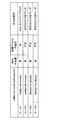
- the MIB content provided by the upper layer every 80 ms is SystemFrameNumber (6 MSs of SystemFrameNumber), subCarrierSpacingCommon, Ssb-subcarrierOffset, Dmrs-TypeA-Position, pdcchConfigSIB1, cellBarred, intraFreqReselection, spare.
- the MIB content generated based on the physical layer is 4 LSBs of SystemFrameNumber, Ssb-IndexExplicit, and Half-frame-index.
- the first frequency band may be a frequency band lower than 6 GHz (sub-6), and the second frequency band may be a frequency band higher than 6 GHz (above-6).
- the first frequency band may be called FR (Frequency Range) 1.
- the second frequency band may be a frequency band higher than 24 GHz, and may be called FR2, above-24, millimeter wave, or the like.
- SystemFrameNumber notifies the upper 6 bits of the system frame number (SFN).
- the subCarrierSpacingCommon reports subcarrier spacing (SCS, Numerology) for RMSI reception.
- Ssb-subcarrierOffset reports PRB (Physical Resource Block) grid offset for RMSI reception.
- Dmrs-TypeA-Position indicates whether the DMRS symbol position for PDSCH is the third symbol or the fourth symbol in the slot.
- the pdcchConfigSIB1 notifies a parameter set (PDCCH parameter set) of PDCCH (or CORESET (Control Resource Set) including the PDCCH, RMSI CORESET) for RMSI reception.
- intraFreqReselection indicates whether there is a camp-on-enabled cell in the same frequency (carrier band) (allowed / not allowed).
- spare is a spare bit and may be used for a specific purpose.
- Ssb-Index Explicit reports the upper 3 bits of the SSB index.
- one bit of Ssb-IndexExplicit is used together with Ssb-subcarrierOffset.
- the maximum number of SSB indexes is 64, 6 bits may be required. In above-6, the number of SSB indexes may be more than eight, and in sub-6, the number of SSB indexes may not be more than eight. In sub-6, one specific bit of Ssb-IndexExplicit is combined with four bits of Ssb-subcarrierOffset, and is used to set Ssb-subcarrierOffset to five bits. The lower 3 bits may be implicitly notified using DMRS for PBCH.
- Half-frame-index indicates whether this SSB is a first half 5 ms half frame or a second half 5 ms half frame of a radio frame (10 ms).
- the CRC is a code of a cyclic redundancy check generated based on the above information.
- the entire PBCH is 56 bits including 24 bits for the upper layer, 8 bits for the physical layer, and 24 bits for the CRC.
- Ssb-subcarrierOffset represents the offset between the PRB (PRB for data) based on the center frequency of the carrier and the PRB of SSB by the number of subcarriers. For example, when subcarrier intervals of SSB and RMSI are the same, since one PRB is 12 subcarriers, Ssb-subcarrierOffset uses 12 code points (value of 0-11) of 4 bits.
- bits and / or code points may be left over.
- a code point is a value represented by a bit.
- one bit of Ssb-IndexExplicit is used together with Ssb-subcarrierOffset, and the remaining two bits are left.
- Ssb-subcarrierOffset uses up to 12 code points (values of 0 to 11) out of 16 code points of 4 bits, at least 4 code points are not used (reserved).
- Ssb-subcarrierOffset uses up to 24 code points (values of 0 to 23) out of 32 code points of 5 bits in combination with 1 bit of Ssb-IndexExplicit, at least 8 code points are used. I can not do it.
- the number of PDCCH parameter sets supported varies depending on the combination of the SCS of the SSB and the subCarrierSpacingCommon.
- FIG. 3 is a diagram illustrating an example of Ssb-subcarrierOffset.
- the frequency position where the center of the carrier can be located is called a channel raster.
- NR The frequency position where the center of the carrier can be located.
- PRBs for data are arranged with channel rasters as PRB boundaries.
- the frequency position to search for SSB at initial access is called SS (Synchronization Signal) raster (or sync raster).
- SS Synchronization Signal
- the specification defines the frequency position of at least one SS raster.
- the PRB for SSB places the SS raster as a PRB boundary.
- At least one SS raster is arranged in the band of carriers arranged based on the channel raster.
- the channel raster spacing is 15 kHz and the SS raster spacing is 1.44 MHz. Also, for example, in the range of 24.25 GHz to 100 GHz, the channel raster spacing is 60 kHz and the SS raster spacing is 17.28 MHz.
- the SS raster spacing is wider than the channel raster spacing.
- the data PRB boundary may not match the SSB PRB boundary.
- the UE searches SSB on SS raster at initial access.
- the UE needs to read an RMSI (or SIB) including information on a random access channel (RACH). Therefore, in the NR cell for standalone (SA), an RMSI linked to the SSB for initial access is transmitted.
- SSBs not used for initial access for example, SSBs of cells used only for secondary cells (SCells) (for example, NR cells for non-standalone (NSA), cells for NSA)
- SCells secondary cells
- NSA non-standalone
- RMSI radio frequency fingerprinting
- cellBarred Barred, and if all cells in the carrier are cells for NSA, intraFreqReselection is not allowed.
- the operation shown in FIG. 4 can be considered as an example of the operation of the initial access of the UE.
- the UE When the UE starts the initial access (S110), it moves the frequency position for searching SSB to the next defined SS raster (S120). Thereafter, the UE determines whether an SSB has been detected (S130).
- the UE moves the process to S120 (search SSB in next SS raster).
- the UE determines whether cellBarred of the PBCH is barred (S140).
- the UE determines whether intraFreqReselection of PBCH is allowed (S210).
- the UE moves the process to S130 (confirms another SSB detected in the same carrier band).
- the UE When cellBarred is not barred (S140: not barred), the UE reads SIB1 in the RMSI associated with SSB (S150). Thereafter, the UE determines whether the cell is accessible (S160).
- PLMN Public Land Mobile Network
- the UE If accessible (S160: Yes), the UE reads another RMSI, performs random access (S170), establishes an RRC connection (S180), and terminates this flow.
- the UE can detect an accessible SSB by sequentially searching a plurality of SS rasters predefined in the specification, and perform random access based on the RMSI linked to the SSB. .
- Case 1 In the SSB of a cell, if cellBarred is notBarred, intraFreqReselection is allowed, and there is an RMSI linked to the SSB and the cell can be accessed, the UE can use the cell (carrier) to access.
- Case 2 In the SSB of a cell, if cellBarred is notBarred, intraFreqReselection is allowed, and an RMSI linked to the SSB is present and the cell can not be accessed, the UE proceeds to the next SS raster Search If not accessible, for example, the PLMN-ID is not an available PLMN-ID.
- Case 3 In the SSB of a cell, if cellBarred is Barred, intraFreqReselection is not allowed, and there is no RMSI linked to the SSB, and the cell can not be accessed, the UE will go to the next SS. Search rasters.
- Case 4 In the SSB of a cell, cellBarred is Barred, intraFreqReselection is not allowed, and RMSI (for Automatic Neighbor Relation (ANR)) linked to the SSB exists and the cell can not be accessed If so, the UE searches for the next SS raster.
- the base station receives neighboring cell information from the UE and automatically updates the neighboring cell list based on the information.
- ANR is similar to a self-organizing network (SON).
- a network supporting ANR sends an RMSI (SIB) even if it is a cell for NSA, and a UE supporting ANR reads the RMSI.
- the RMSI may be transmitted. Therefore, it may be necessary to notify the UE that there is no RMSI associated with the received SSB. If there is no RMSI associated with the received SSB, the UE does not need to read the RMSI even though it supports ANR.
- the following two notification methods can be considered as a notification method indicating that there is no RMSI associated with the received SSB.
- Notification method 1 One of 8-bit pdcchConfigSIB1 that is not used is used to indicate that there is no RMSI.
- Notification method 2 An unused code point (value) of Ssb-subcarrierOffset is used to indicate that the RMSI does not exist. If RMSI does not exist, pdcchConfigSIB1 is used to notify the next SS raster (or sync raster) where the UE should search for the SSB defining the cell.
- notification method 1 the UE can not obtain information of SS raster to search for SSB next.
- notification method 2 information on SS rasters for which SSB should be searched next can be acquired using pdcchConfigSIB1 when there is no RMSI as in case 3 but in case 2 or 4 Such information can not be obtained.
- the frequency position of the SSB of the NSA cell (SSB for NSA) is not searched by the UE at initial access, but is indicated by the network. This frequency location may be indicated by the configuration of measurements via higher layers (e.g. the RRC information element measObject).
- the frequency position of the NSA SSB may be other than the SS raster. Therefore, the SSB PRB boundary of the NSA SSB may coincide with the data PRB boundary. In this case, the 4 bits of Ssb-subcarrierOffset are always 0 and can not be used effectively.
- bits and / or code points in the PBCH are not used effectively.
- the inventor effectively reduces the load on the UE and / or improves the detection performance of the PBCH by effectively utilizing the bits and / or code points in the PBCH and increasing the amount of information notified by the limited PBCH. I thought of realizing it.
- the interpretation of the specific information element (at least a part of the MIB content) in the PBCH differs depending on whether or not the specific condition holds.
- the specific condition in the first aspect is that cellBarred is Barred and intraFreqReselection is not allowed in SSB found on the SS raster at the time of initial access.
- the UE may recognize that the SSB is an NSA SSB based on the received SSB. Since the received SSB indicates Barred and not allowed, the SSB is the SSB of the NSA cell (SSB for NSA).
- the SSA for NSA need not be located on the SS raster, but may be located on the SS raster.
- the received SSB is located on the SS raster since the UE performing the initial access searches the SSB on the SS raster. Therefore, even if the SSB is located on the SS raster, it is not the initial access SSB. In this case, the UE searches for SS rasters in another carrier band.
- the SSB PRB boundary of the SSB for NSA may coincide with the data PRB boundary. Therefore, there is a possibility that the SSB PRB boundary of the NSA SSB matches the data PRB boundary, and the NSA SSB is located on the SS raster.
- the UE may assume that there is no misalignment between the SSB PRB boundary and the data PRB boundary.
- 5 bits of Ssb-subcarrierOffset including 1 bit of Ssb-IndexExplicit in sub-6 or 4 bits of Ssb-subcarrierOffset in above-6 may be used for another application.
- the received SSB is an NSA SSB, there may not be an RMSI CORESET associated with the SSB. Further, if the received SSB is an SSA for NSA and there is an RMSI CORESET for ANR linked to the SSB, the RMSI CORESET may be set by the upper layer. Therefore, when the received SSB is an SSA SSB, the UE may assume that the SSB does not notify the configuration of the RMSI CORESET associated with the SSB. In this case, the eight bits of pdcchConfigSIB1 may be used for another application.
- the SCS for RMSI reception may be configured by higher layers. Thus, if the received SSB is an NSA SSB, the UE may assume that the SSB does not notify the SCS for RMSI reception. In this case, one bit of subCarrierSpacingCommon may be used for another application.
- At least some bits and / or code points (specific information element) of Ssb-IndexExplicit, Ssb-subcarrierOffset, pdcchConfigSIB1, subCarrierSpacingCommon may be used for other applications.
- the specific information element may indicate information that can be used to determine the SS raster position to search SSB next. For example, the offset from the frequency position of the received SSB to the frequency position of the SSB for standalone (SA) may be indicated. For example, the specific information element may indicate the offset (for example, the offset of the SS raster index) of the SS raster from the SS raster where the received SSB is located to the SS raster where the SSB for SA is located. Also, the specific information element may indicate the range or number of SS rasters to be skipped from the SS raster in which the received SSB is located to the SS raster that the UE should search for the next initial access.
- the UE can know the SS raster to be searched next at the initial access, and by skipping the search of unnecessary SS rasters, the initial access delay and / or power consumption can be obtained. Can be reduced. Also, information that can be used to determine the SS raster position to search for the SSB next as described above may be included in the RMSI (eg, SIB1) and transmitted. In cases 2 and 4, since there is an RMSI associated with the SSB, the UE can read the SIB 1 and obtain information that can be used to reduce initial access delay and / or power consumption.
- RMSI eg, SIB1
- the UE may search for all SA SSBs on the SS raster or may search until one SA SSB is detected.
- the specific information element may indicate at least a part of a country code (Mobile Country Code: MCC), a network code (Mobile Network Code: MNC), and a PLMN-ID.
- MCC Mobile Country Code
- MNC Mobile Network Code
- PLMN-ID a part of a country code
- the UE can know the country and / or network, and the operator to be searched based on the country and / or network and information obtained from SIM (Subscriber Identity Module) etc., At least one of the band, SS raster can be narrowed. Therefore, the delay of the initial access can be suppressed.
- SIM Subscriber Identity Module
- Different notification methods and UE actions may be applied in case 3 (in the absence of RMSI for ANR) and in case 4 (in the presence of RMSI for ANR). That is, one bit of Ssb-subcarrierOffset or one bit of spare (spare bit) is a specific information element, and may indicate case 3 or case 4 (case information). Or whether 1 bit of Ssb-subcarrierOffset or 1 bit of spare (spare bit) is a specific information element and cellBarred is Barred whether or not to read SIB1 (ie, SIB1 includes information useful for initial access) May be displayed.
- the remaining bits of the case information in Ssb-subcarrierOffset, pdcchConfigSIB1, and subCarrierSpacingCommon are specific information elements, and the frequency position of the SS raster to be searched next, the range of the skipable SS raster, etc. It may be shown, or at least a part of MCC, MNC, PLMN-ID may be shown.
- the SIB1 in the RMSI linked to the SSB may indicate the frequency position of the SS raster to be searched next, the range of the skipable SS raster, and the like.
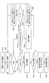
- FIG. 6 is a flowchart showing an example of the operation of initial access according to the first aspect.
- the UE When the UE starts the initial access (S110), it moves the frequency position for searching SSB to the next defined SS raster (S120). Thereafter, the UE determines whether an SSB has been detected (S130).
- the UE moves the process to S120 (search SSB in next SS raster).
- the UE determines whether cellBarred of the PBCH is barred (S140).
- the UE determines whether intraFreqReselection of PBCH is allowed (S210).
- the UE determines whether or not Case 4 (there is an RMSI associated with SSB) (S220).
- case 3 the UE skips several SS rasters based on the MIB content (S230), and shifts the process to S120 (search SSB in another carrier band).
- the UE reads SIB1 in the RMSI linked to the SSB (S240).
- the SIB 1 may indicate the frequency position of the SS raster to be searched next (or the range of the SS raster that can be skipped, etc.). Thereafter, the UE skips several SS rasters based on the SIB1 content (S250), and shifts the processing to S120 (search SSB in another carrier band).
- the UE When cellBarred is not barred (S140: not barred), the UE reads SIB1 in the RMSI associated with SSB (S150). Thereafter, the UE determines whether the cell is accessible (S160).
- the UE shifts the processing to S250.
- the UE If accessible (S160: Yes, Case 1), the UE reads another RMSI, performs random access (S170), establishes an RRC connection (S180), and terminates this flow.
- the information on the SS raster to be searched next can be notified, so that the UE can suppress the initial access delay.
- the specific condition in the second aspect is that the connected (CONNECTED mode) UE is instructed to measure SSB at frequency positions other than SS raster.
- the frequency position of the SSB to be measured is indicated via the upper layer (for example, an information element measurement object (measObject) of RRC signaling).
- the UE may assume that the SSB to be measured is an SSA for NSA since the SSB to be measured is not located on the SS raster.
- the UE has no gap between the SSB PRB boundary and the data PRB boundary , May be assumed.
- 5 bits of Ssb-subcarrierOffset including 1 bit of Ssb-IndexExplicit in sub-6 or 4 bits of Ssb-subcarrierOffset in above-6 may be used for another application.
- the received SSB when the received SSB is an NSA SSB, there may not be an RMSI CORESET associated with the SSB. Further, if the received SSB is an SSA for NSA and there is an RMSI CORESET for ANR linked to the SSB, the RMSI CORESET may be set by the upper layer. Therefore, when the received SSB is an SSA SSB, the UE may assume that the SSB does not notify the configuration of the RMSI CORESET associated with the SSB. In this case, the eight bits of pdcchConfigSIB1 may be used for another application.
- the SCS for RMSI reception may be configured by the upper layer.
- the UE may assume that the SSB does not notify the SCS for RMSI reception.
- one bit of subCarrierSpacingCommon may be used for another application.
- the UE may assume Barred and not allowed. In this case, cellBarred and intraFreqReselection may be used for another application.
- At least some bits and / or code points (specific information element) of Ssb-IndexExplicit, Ssb-subcarrierOffset, pdcchConfigSIB1, subCarrierSpacingCommon, cellBarred, intraFreqReselection are used for other uses. It may be done.
- the specific information element may indicate information that the connected UE should read from the PBCH, or may indicate information that may differ from cell to cell.
- the specific information element may indicate timing related information indicating time resources of SSB and / or DMRS.
- the timing related information may indicate at least a part of SystemFrameNumber, Half-frame-index, SSB index (implicit notification and / or explicit notification (Ssb-Index Explicit)), and Dmrs-TypeA-Position.
- the UE read the timing related information from the PBCH in the carrier for which measurement is instructed, since the timings do not necessarily match between the carriers. Further, since the timing related information may be different for each cell, if the upper layer reports timing related information for each cell, the overhead will be large. Thus, the timing related information can not be read again (not used for another application).
- timing related information may be notified using a specific information element.
- timing related information may be repeatedly transmitted using a specific information element. According to this repeated transmission, the detection rate of timing related information can be improved.
- the specific information element may indicate a fixed value previously defined in the specification.
- the detection rate can be improved by the UE decoding the PBCH assuming a specific information element as a fixed value.
- the UE may decode timing related information by using a fixed value as a reference (known value).
- the timing related information may be encoded, and the encoded information may be notified using the information element of the timing related information and the specific information element.
- the specific information element may be a redundant code for timing related information.
- the specific information element may be information used for decoding of timing related information.
- the specific information element may indicate measurement related information regarding the measurement of SSB.
- the measurement related information may indicate the frequency position of another SSB.
- the upper layer may indicate the frequency position of the SSB to be measured, and the specific information element of the SSB may indicate the frequency position of another SSB.
- the UE may measure the SSB indicated by the upper layer and the SSB indicated by the measurement related information. For example, if the UE supports a wide band and multiple SSBs are located at different frequency locations within that band, measurement time can be reduced compared to when multiple SSBs are located at different time locations. .
- the measurement related information may include the actual transmission period of SSB per cell.
- this transmission cycle may be an SS burst set cycle.
- the SSB measurement timing configuration (SMTC) based on the upper layer includes a measurement period of SSB. Also, SMTC may be notified to the idle UE by the SIB.
- the measurement requires a large number of measurement cycles, and thus the measurement takes time.
- the SS burst set period is shorter than the SMTC measurement period, the SSB may notify the SS burst set period, and the UE may switch the receiving beam for each SS burst set period to measure the SSB. In this case, the time required for the measurement can be shortened as compared with the case of using the measurement cycle.
- the specific information element may indicate QCL related information on pseudo co-location (QCL) between SSBs. If the large-scale nature of channels carrying one SSB can be inferred from channels carrying another SSB, those SSBs are QCLs.
- the large scale properties include, for example, at least one of delay spread, Doppler spread, Doppler shift, average gain, average delay, and spatial reception parameters.
- the spatial reception parameter is, for example, a beam (eg, a transmit beam).
- the QCL related information in a certain SSB may include the SSB index of the SSB quasi-co-located with the SSB.
- a plurality of QCL patterns indicating SSB indexes in a QCL relationship may be defined by the specification, or may be set by the upper layer.
- the QCL related information may include the index of the QCL pattern.
- a long measurement time is required because only one SSB can be measured for one base station beam in one SS burst set.
- the UE may apply different receive beams to multiple SSBs. Multiple SSBs can be measured for one base station beam in one SS burst set. Therefore, measurement delay can be suppressed or measurement accuracy can be improved.
- Measurement related information and / or QCL related information may be notified by the upper layer.
- measurement related information and / or QCL related information may differ from cell to cell, there is a large overhead when upper layer reports measurement related information and / or QCL related information for each cell.
- the specific condition in the third aspect is that the connected UE is instructed to measure the SSB, and the specific parameter set by the upper layer is a measurement value.
- the specific parameter may be a bitmap indicating whether each SSB is to be measured. This bitmap has bits corresponding to all SSB indexes. When each bit is 1, it indicates that the corresponding SSB is to be transmitted, and when it is 0, it indicates that the corresponding SSB is not transmitted. If all bits after the specific position of the bit map are 0, some or all of Ssb-IndexExplicit will be 0 and may be used for other applications.
- the number of SSB indexes is at most 64.
- bits # 0 to # 63 in the bit map when all bits # 32 to # 63 are 0, the UE can narrow the SSB index of SSB to be searched to # 0 to # 31, and Ssb-IndexExplicit One bit of may be used for another application.
- At least some bits and / or code points (specific information elements) of Ssb-IndexExplicit may be used for other applications.
- the specific information element may indicate at least one of timing related information, measurement related information, and QCL related information. Similar to the second aspect, the specific information element may be used for repetition of timing related information, coding of timing related information, and a fixed value.
- the specific condition in the fourth aspect may be that the connected UE is instructed to measure SSB in a specific frequency band.
- the specific frequency band may be FR2.
- Ssb-subcarrierOffset may be used for another application.
- one or two bits of spare may be used for another application, since Ssb-subcarrierOffset may be used.
- At least some bits of Ssb-subcarrierOffset, spare, and / or code points (specific information element) may be used for another application.
- the specific information element may indicate QCL related information.
- FR2 when the UE performs receive beamforming using analog beamforming (BF), since only one receive beam can be used for one measurement, measurement is performed over the time of measurement period ⁇ number of receive beams. Do. Therefore, measurement delay is concerned.
- BF analog beamforming
- the specific information element may notify QCL related information indicating that multiple SSBs in the same SS burst set are transmitted using the same base station beam. According to the QCL related information, measurement delay can be suppressed.
- parameters that may be different for each cell are preferably notified by the PBCH because the upper layer will increase overhead if notified by the upper layer for each cell to be measured.
- parameters set by the NR secondary network may not be shared with the LTE master network (MN).
- the specific information element may differ depending on whether the received SSB is located on the SS raster. Also, for example, the specific information element may be different depending on whether or not the UE performs initial access. Also, for example, the specific information element may differ depending on whether or not the UE is connected. Also, for example, the specific information element may differ depending on whether or not there is an RMSI associated with the received SSB.
- wireless communication system Wireless communication system
- communication is performed using any one or a combination of the wireless communication methods according to the above embodiments of the present invention.
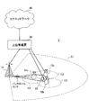
- FIG. 7 is a diagram showing an example of a schematic configuration of a wireless communication system according to an embodiment of the present invention.
- the radio communication system 1 applies carrier aggregation (CA) and / or dual connectivity (DC) in which a plurality of basic frequency blocks (component carriers) each having a system bandwidth (for example, 20 MHz) of the LTE system as one unit are integrated. can do.
- CA carrier aggregation
- DC dual connectivity
- the wireless communication system 1 includes LTE (Long Term Evolution), LTE-A (LTE-Advanced), LTE-B (LTE-Beyond), SUPER 3G, IMT-Advanced, 4G (4th generation mobile communication system), and 5G. It may be called (5th generation mobile communication system), NR (New Radio), FRA (Future Radio Access), New-RAT (Radio Access Technology) or the like, or may be called a system for realizing these.
- the radio communication system 1 includes a radio base station 11 forming a macrocell C1 with a relatively wide coverage, and radio base stations 12 (12a to 12c) disposed in the macrocell C1 and forming a small cell C2 narrower than the macrocell C1. And. Moreover, the user terminal 20 is arrange
- the user terminal 20 can be connected to both the radio base station 11 and the radio base station 12. It is assumed that the user terminal 20 simultaneously uses the macro cell C1 and the small cell C2 by CA or DC. Also, the user terminal 20 may apply CA or DC using a plurality of cells (CCs) (for example, 5 or less CCs, 6 or more CCs).
- CCs cells
- Communication can be performed between the user terminal 20 and the radio base station 11 using a relatively low frequency band (for example, 2 GHz) and a narrow bandwidth carrier (also called an existing carrier, legacy carrier, etc.).
- a carrier having a wide bandwidth in a relatively high frequency band for example, 3.5 GHz, 5 GHz, etc.
- the configuration of the frequency band used by each wireless base station is not limited to this.
- a wired connection for example, an optical fiber conforming to a Common Public Radio Interface (CPRI), an X2 interface, etc.
- a wireless connection for example, an optical fiber conforming to a Common Public Radio Interface (CPRI), an X2 interface, etc.
- CPRI Common Public Radio Interface
- X2 interface X2 interface
- the radio base station 11 and each radio base station 12 are connected to the higher station apparatus 30 and connected to the core network 40 via the higher station apparatus 30.
- the upper station apparatus 30 includes, for example, an access gateway apparatus, a radio network controller (RNC), a mobility management entity (MME), and the like, but is not limited thereto. Further, each wireless base station 12 may be connected to the higher station apparatus 30 via the wireless base station 11.
- RNC radio network controller
- MME mobility management entity
- the radio base station 11 is a radio base station having a relatively wide coverage, and may be called a macro base station, an aggregation node, an eNB (eNodeB), a transmission / reception point, or the like.
- the radio base station 12 is a radio base station having local coverage, and is a small base station, a micro base station, a pico base station, a femto base station, a HeNB (Home eNodeB), an RRH (Remote Radio Head), transmission and reception It may be called a point or the like.
- the radio base stations 11 and 12 are not distinguished, they are collectively referred to as the radio base station 10.
- Each user terminal 20 is a terminal compatible with various communication schemes such as LTE and LTE-A, and may include not only mobile communication terminals (mobile stations) but also fixed communication terminals (fixed stations).
- orthogonal frequency division multiple access (OFDMA) is applied to the downlink as a radio access scheme, and single carrier frequency division multiple access (SC-FDMA: single carrier) to the uplink.
- SC-FDMA single carrier frequency division multiple access
- Frequency Division Multiple Access and / or OFDMA is applied.
- OFDMA is a multicarrier transmission scheme in which a frequency band is divided into a plurality of narrow frequency bands (subcarriers) and data is mapped to each subcarrier to perform communication.
- SC-FDMA is a single carrier transmission scheme in which system bandwidth is divided into bands having one or continuous resource blocks for each terminal, and a plurality of terminals use different bands to reduce interference between the terminals. is there.
- the uplink and downlink radio access schemes are not limited to these combinations, and other radio access schemes may be used.
- a downlink shared channel (PDSCH: Physical Downlink Shared Channel) shared by each user terminal 20, a broadcast channel (PBCH: Physical Broadcast Channel), a downlink L1 / L2 control channel, etc. are used as downlink channels. Used. User data, upper layer control information, SIB (System Information Block) and the like are transmitted by the PDSCH. Also, a MIB (Master Information Block) is transmitted by the PBCH.
- PDSCH Physical Downlink Shared Channel
- PBCH Physical Broadcast Channel
- SIB System Information Block
- MIB Master Information Block
- the downlink L1 / L2 control channel includes PDCCH (Physical Downlink Control Channel), EPDCCH (Enhanced Physical Downlink Control Channel), PCFICH (Physical Control Format Indicator Channel), PHICH (Physical Hybrid-ARQ Indicator Channel) and the like.
- Downlink control information (DCI) including scheduling information of PDSCH and / or PUSCH is transmitted by PDCCH.
- scheduling information may be notified by DCI.
- DCI scheduling DL data reception may be referred to as DL assignment
- DCI scheduling UL data transmission may be referred to as UL grant.
- the number of OFDM symbols used for PDCCH is transmitted by PCFICH.
- Delivery confirmation information (for example, also referred to as retransmission control information, HARQ-ACK, or ACK / NACK) of HARQ (Hybrid Automatic Repeat reQuest) for the PUSCH is transmitted by the PHICH.
- the EPDCCH is frequency division multiplexed with a PDSCH (downlink shared data channel), and is used for transmission such as DCI, similarly to the PDCCH.
- an uplink shared channel (PUSCH: Physical Uplink Shared Channel) shared by each user terminal 20, an uplink control channel (PUCCH: Physical Uplink Control Channel), a random access channel (PRACH: Physical Random Access Channel) or the like is used.
- User data, upper layer control information, etc. are transmitted by PUSCH.
- downlink radio quality information (CQI: Channel Quality Indicator), delivery confirmation information, scheduling request (SR: Scheduling Request), etc. are transmitted by the PUCCH.
- the PRACH transmits a random access preamble for establishing a connection with a cell.
- a cell-specific reference signal (CRS: Cell-specific Reference Signal), a channel state information reference signal (CSI-RS: Channel State Information-Reference Signal), a demodulation reference signal (DMRS: DeModulation Reference Signal, positioning reference signal (PRS), etc.
- CRS Cell-specific Reference Signal
- CSI-RS Channel State Information-Reference Signal
- DMRS DeModulation Reference Signal
- PRS positioning reference signal
- SRS Sounding Reference Signal
- DMRS demodulation reference signal
- PRS positioning reference signal
- DMRS Demodulation reference signal
- PRS positioning reference signal
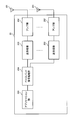
- FIG. 8 is a diagram showing an example of the entire configuration of a radio base station according to an embodiment of the present invention.
- the radio base station 10 includes a plurality of transmitting and receiving antennas 101, an amplifier unit 102, a transmitting and receiving unit 103, a baseband signal processing unit 104, a call processing unit 105, and a transmission path interface 106.
- each of the transmitting and receiving antenna 101, the amplifier unit 102, and the transmitting and receiving unit 103 may be configured to include one or more.
- User data transmitted from the radio base station 10 to the user terminal 20 by downlink is input from the higher station apparatus 30 to the baseband signal processing unit 104 via the transmission path interface 106.
- the baseband signal processing unit 104 performs packet data convergence protocol (PDCP) layer processing, user data division / combination, RLC layer transmission processing such as RLC (Radio Link Control) retransmission control, and MAC (Medium Access) for user data.
- Control Transmission processing such as retransmission control (for example, HARQ transmission processing), scheduling, transmission format selection, channel coding, inverse fast Fourier transform (IFFT) processing, precoding processing, etc. It is transferred to 103. Further, transmission processing such as channel coding and inverse fast Fourier transform is also performed on the downlink control signal and transferred to the transmission / reception unit 103.
- the transmission / reception unit 103 converts the baseband signal output from the baseband signal processing unit 104 for each antenna into a radio frequency band and transmits the baseband signal.
- the radio frequency signal frequency-converted by the transmitting and receiving unit 103 is amplified by the amplifier unit 102 and transmitted from the transmitting and receiving antenna 101.
- the transmission / reception unit 103 can be configured of a transmitter / receiver, a transmission / reception circuit, or a transmission / reception device described based on the common recognition in the technical field according to the present invention.
- the transmitting and receiving unit 103 may be configured as an integrated transmitting and receiving unit, or may be configured from a transmitting unit and a receiving unit.
- the radio frequency signal received by the transmission / reception antenna 101 is amplified by the amplifier unit 102.
- the transmitting and receiving unit 103 receives the upstream signal amplified by the amplifier unit 102.
- the transmission / reception unit 103 frequency-converts the received signal into a baseband signal and outputs the result to the baseband signal processing unit 104.
- the baseband signal processing unit 104 performs Fast Fourier Transform (FFT) processing, Inverse Discrete Fourier Transform (IDFT) processing, and error correction on user data included in the input upstream signal. Decoding, reception processing of MAC retransmission control, and reception processing of RLC layer and PDCP layer are performed, and are transferred to the higher station apparatus 30 via the transmission path interface 106.
- the call processing unit 105 performs call processing (setting, release, etc.) of the communication channel, state management of the radio base station 10, management of radio resources, and the like.
- the transmission path interface 106 transmits and receives signals to and from the higher station apparatus 30 via a predetermined interface. Also, the transmission path interface 106 transmits / receives signals (backhaul signaling) to / from the other wireless base station 10 via an inter-base station interface (for example, an optical fiber conforming to CPRI (Common Public Radio Interface), X2 interface). May be
- an inter-base station interface for example, an optical fiber conforming to CPRI (Common Public Radio Interface), X2 interface.
- the transmission / reception unit 103 may transmit a synchronization signal block (for example, SSB, SS / PBCH block) including a broadcast channel (for example, PBCH).
- a synchronization signal block for example, SSB, SS / PBCH block
- a broadcast channel for example, PBCH
- FIG. 9 is a diagram showing an example of a functional configuration of a wireless base station according to an embodiment of the present invention.
- the functional block of the characteristic part in this embodiment is mainly shown, and the wireless base station 10 also has another functional block required for wireless communication.
- the baseband signal processing unit 104 at least includes a control unit (scheduler) 301, a transmission signal generation unit 302, a mapping unit 303, a reception signal processing unit 304, and a measurement unit 305. Note that these configurations may be included in the wireless base station 10, and some or all of the configurations may not be included in the baseband signal processing unit 104.
- a control unit (scheduler) 301 performs control of the entire radio base station 10.
- the control unit 301 can be configured of a controller, a control circuit, or a control device described based on the common recognition in the technical field according to the present invention.
- the control unit 301 controls, for example, generation of a signal by the transmission signal generation unit 302, assignment of a signal by the mapping unit 303, and the like. Further, the control unit 301 controls reception processing of a signal by the reception signal processing unit 304, measurement of a signal by the measurement unit 305, and the like.
- the control unit 301 schedules (for example, resources) system information, downlink data signals (for example, signals transmitted on PDSCH), downlink control signals (for example, signals transmitted on PDCCH and / or EPDCCH, delivery confirmation information, etc.) Control allocation). Further, the control unit 301 controls generation of the downlink control signal, the downlink data signal, and the like based on the result of determining whether the retransmission control for the uplink data signal is necessary or not. The control unit 301 also controls scheduling of synchronization signals (for example, PSS (Primary Synchronization Signal) / SSS (Secondary Synchronization Signal), downlink reference signals (for example, CRS, CSI-RS, DMRS) and the like.
- PSS Primary Synchronization Signal
- SSS Synchronization Signal
- control unit 301 may perform uplink data signals (for example, signals transmitted on PUSCH), uplink control signals (for example, signals transmitted on PUCCH and / or PUSCH, delivery confirmation information, etc.), random access preambles (for example, It controls scheduling of signals transmitted on PRACH, uplink reference signals and the like.
- uplink data signals for example, signals transmitted on PUSCH
- uplink control signals for example, signals transmitted on PUCCH and / or PUSCH, delivery confirmation information, etc.
- random access preambles for example, It controls scheduling of signals transmitted on PRACH, uplink reference signals and the like.
- the transmission signal generation unit 302 generates a downlink signal (downlink control signal, downlink data signal, downlink reference signal or the like) based on an instruction from the control unit 301, and outputs the downlink signal to the mapping unit 303.
- the transmission signal generation unit 302 can be configured from a signal generator, a signal generation circuit or a signal generation device described based on the common recognition in the technical field according to the present invention.
- the transmission signal generation unit 302 generates, for example, DL assignment for notifying downlink data allocation information and / or UL grant for notifying uplink data allocation information, based on an instruction from the control unit 301.
- DL assignment and UL grant are both DCI and follow DCI format.
- coding processing and modulation processing are performed on the downlink data signal according to a coding rate, a modulation method, and the like determined based on channel state information (CSI: Channel State Information) and the like from each user terminal 20.
- CSI Channel State Information
- Mapping section 303 maps the downlink signal generated by transmission signal generation section 302 to a predetermined radio resource based on an instruction from control section 301, and outputs the mapped downlink signal to transmission / reception section 103.
- the mapping unit 303 may be configured of a mapper, a mapping circuit or a mapping device described based on the common recognition in the technical field according to the present invention.
- the reception signal processing unit 304 performs reception processing (for example, demapping, demodulation, decoding, and the like) on the reception signal input from the transmission / reception unit 103.
- the reception signal is, for example, an uplink signal (uplink control signal, uplink data signal, uplink reference signal, etc.) transmitted from the user terminal 20.
- the received signal processing unit 304 can be configured from a signal processor, a signal processing circuit or a signal processing device described based on the common recognition in the technical field according to the present invention.
- the reception signal processing unit 304 outputs the information decoded by the reception process to the control unit 301. For example, when the PUCCH including the HARQ-ACK is received, the HARQ-ACK is output to the control unit 301. Further, the reception signal processing unit 304 outputs the reception signal and / or the signal after reception processing to the measurement unit 305.
- the measurement unit 305 performs measurement on the received signal.
- the measuring unit 305 can be configured from a measuring device, a measuring circuit or a measuring device described based on the common recognition in the technical field according to the present invention.
- the measurement unit 305 may perform Radio Resource Management (RRM) measurement, Channel State Information (CSI) measurement, and the like based on the received signal.
- the measurement unit 305 may use received power (for example, RSRP (Reference Signal Received Power)), received quality (for example, RSRQ (Reference Signal Received Quality), SINR (Signal to Interference plus Noise Ratio)), signal strength (for example, RSSI (for example). Received Signal Strength Indicator), propagation path information (eg, CSI), etc. may be measured.
- the measurement result may be output to the control unit 301.
- control unit 301 may interpret (read) the specific information element in the broadcast channel as a different information element depending on whether the specific condition is satisfied.
- FIG. 10 is a diagram showing an example of the entire configuration of a user terminal according to an embodiment of the present invention.
- the user terminal 20 includes a plurality of transmitting and receiving antennas 201, an amplifier unit 202, a transmitting and receiving unit 203, a baseband signal processing unit 204, and an application unit 205.
- each of the transmitting and receiving antenna 201, the amplifier unit 202, and the transmitting and receiving unit 203 may be configured to include one or more.
- the radio frequency signal received by the transmission / reception antenna 201 is amplified by the amplifier unit 202.
- the transmitting and receiving unit 203 receives the downlink signal amplified by the amplifier unit 202.
- the transmission / reception unit 203 frequency-converts the received signal into a baseband signal and outputs the result to the baseband signal processing unit 204.
- the transmission / reception unit 203 can be configured of a transmitter / receiver, a transmission / reception circuit or a transmission / reception device described based on the common recognition in the technical field according to the present invention.
- the transmission / reception unit 203 may be configured as an integrated transmission / reception unit, or may be configured from a transmission unit and a reception unit.
- the baseband signal processing unit 204 performs reception processing of FFT processing, error correction decoding, retransmission control, and the like on the input baseband signal.
- the downlink user data is transferred to the application unit 205.
- the application unit 205 performs processing on a layer higher than the physical layer and the MAC layer. Moreover, broadcast information may also be transferred to the application unit 205 among downlink data.
- uplink user data is input from the application unit 205 to the baseband signal processing unit 204.
- the baseband signal processing unit 204 performs transmission processing of retransmission control (for example, transmission processing of HARQ), channel coding, precoding, discrete Fourier transform (DFT) processing, IFFT processing, etc. It is transferred to 203.
- the transmission / reception unit 203 converts the baseband signal output from the baseband signal processing unit 204 into a radio frequency band and transmits it.
- the radio frequency signal frequency-converted by the transmitting and receiving unit 203 is amplified by the amplifier unit 202 and transmitted from the transmitting and receiving antenna 201.
- a synchronization signal block (eg, SSB, SS / PBCH block) including a broadcast channel (eg, PBCH) may be received from the cell.
- a synchronization signal block eg, SSB, SS / PBCH block
- a broadcast channel eg, PBCH
- FIG. 11 is a diagram showing an example of a functional configuration of a user terminal according to an embodiment of the present invention.
- the functional block of the characteristic part in this embodiment is mainly shown, and it is assumed that the user terminal 20 also has other functional blocks necessary for wireless communication.
- the baseband signal processing unit 204 included in the user terminal 20 at least includes a control unit 401, a transmission signal generation unit 402, a mapping unit 403, a reception signal processing unit 404, and a measurement unit 405. Note that these configurations may be included in the user terminal 20, and some or all of the configurations may not be included in the baseband signal processing unit 204.
- the control unit 401 controls the entire user terminal 20.
- the control unit 401 can be configured of a controller, a control circuit, or a control device described based on the common recognition in the technical field according to the present invention.
- the control unit 401 controls, for example, signal generation by the transmission signal generation unit 402, assignment of signals by the mapping unit 403, and the like. Further, the control unit 401 controls reception processing of a signal by the reception signal processing unit 404, measurement of a signal by the measurement unit 405, and the like.
- the control unit 401 acquires the downlink control signal and the downlink data signal transmitted from the radio base station 10 from the reception signal processing unit 404.
- the control unit 401 controls the generation of the uplink control signal and / or the uplink data signal based on the result of determining the necessity of the retransmission control for the downlink control signal and / or the downlink data signal.
- control unit 401 When the control unit 401 acquires various types of information notified from the radio base station 10 from the received signal processing unit 404, the control unit 401 may update parameters used for control based on the information.
- the transmission signal generation unit 402 generates an uplink signal (uplink control signal, uplink data signal, uplink reference signal or the like) based on an instruction from the control unit 401, and outputs the uplink signal to the mapping unit 403.
- the transmission signal generation unit 402 can be configured from a signal generator, a signal generation circuit, or a signal generation device described based on the common recognition in the technical field according to the present invention.
- the transmission signal generation unit 402 generates, for example, an uplink control signal related to delivery confirmation information, channel state information (CSI), and the like based on an instruction from the control unit 401. Further, the transmission signal generation unit 402 generates an uplink data signal based on an instruction from the control unit 401. For example, when the downlink control signal notified from the radio base station 10 includes a UL grant, the transmission signal generation unit 402 is instructed by the control unit 401 to generate an uplink data signal.
- CSI channel state information
- Mapping section 403 maps the uplink signal generated by transmission signal generation section 402 to a radio resource based on an instruction from control section 401, and outputs the uplink signal to transmission / reception section 203.
- the mapping unit 403 may be configured of a mapper, a mapping circuit or a mapping device described based on the common recognition in the technical field according to the present invention.
- the reception signal processing unit 404 performs reception processing (for example, demapping, demodulation, decoding, and the like) on the reception signal input from the transmission / reception unit 203.
- the reception signal is, for example, a downlink signal (a downlink control signal, a downlink data signal, a downlink reference signal, or the like) transmitted from the radio base station 10.
- the received signal processing unit 404 can be composed of a signal processor, a signal processing circuit or a signal processing device described based on the common recognition in the technical field according to the present invention. Also, the received signal processing unit 404 can constitute a receiving unit according to the present invention.
- the reception signal processing unit 404 outputs the information decoded by the reception process to the control unit 401.
- the received signal processing unit 404 outputs, for example, broadcast information, system information, RRC signaling, DCI, and the like to the control unit 401. Further, the reception signal processing unit 404 outputs the reception signal and / or the signal after reception processing to the measurement unit 405.
- the measurement unit 405 performs measurement on the received signal.
- the measuring unit 405 can be configured of a measuring device, a measuring circuit or a measuring device described based on the common recognition in the technical field according to the present invention.
- the measurement unit 405 may perform RRM measurement, CSI measurement, and the like based on the received signal.
- the measurement unit 405 may measure reception power (for example, RSRP), reception quality (for example, RSRQ, SINR), signal strength (for example, RSSI), channel information (for example, CSI), and the like.
- the measurement result may be output to the control unit 401.
- control unit 401 is a specific information element in the broadcast channel (for example, PBCH) (for example, Ssb-IndexExplicit, Ssb-subcarrierOffset, pdcchConfigSIB1, subCarrierSpacingCommon, cellBarred, intraFreqReselection, spare, at least a part of bits and / or code point ) May be interpreted (read) as different information elements depending on whether a specific condition is satisfied.
- PBCH broadcast channel
- the received synchronization signal block (for example, SSB, SS / PBCH block) is one of a plurality of predefined frequency positions (for example, SS raster) for arranging the synchronization signal block for initial access.
- the detected sync signal block indicates that there are no campable cells in the received sync signal block carrier band (eg cellBarred is Barred and intraFreqReselection is not allowed) ) May be.
- the specific information element relates to an information element (for example, Ssb-IndexExplicit and / or Ssb-subcarrierOffset) regarding subcarrier offset of the synchronization signal block, an information element (for example, pdcchConfigSIB1) regarding configuration of downlink physical control channel, and subcarrier spacing It may be at least a part of an information element (for example, subCarrierSpacingCommon).
- an information element for example, Ssb-IndexExplicit and / or Ssb-subcarrierOffset
- pdcchConfigSIB1 regarding configuration of downlink physical control channel
- subcarrier spacing It may be at least a part of an information element (for example, subCarrierSpacingCommon).
- the specific condition is that, in a state where the user terminal is connected to the cell, the user terminal is in synchronization signal blocks at frequency positions other than a plurality of frequency positions defined in advance for arranging synchronization signal blocks for initial access.
- the measurement may be instructed.
- the specific information element relates to an information element (for example, Ssb-IndexExplicit and / or Ssb-subcarrierOffset) regarding subcarrier offset of the synchronization signal block, an information element (for example, pdcchConfigSIB1) regarding configuration of downlink physical control channel, and subcarrier spacing
- an information element e.g., subCarrierSpacingCommon
- an information element related to the possibility of camping on a cell e.g., cellBarred
- an information element related to the possibility of camping on the carrier band of the cell e.g. intraFreqReselection
- the specific condition may be that the specific parameter set by the upper layer is a specific value in a state where the user terminal is connected to the cell.
- the specific information element may be at least a part of an information element (for example, Ssb-IndexExplicit) related to the index of the synchronization signal block.
- control unit 401 controls the specific information element to be information on the frequency position (for example, SS raster) of the synchronization signal block to be searched, the country code (for example, MCC) and / or the network number.
- information on MNC information on MNC
- information on timing of received synchronization signal block for example, timing related information, repetition of timing related information, information used for decoding of timing related information
- received synchronization signal block Information on the measurement of the synchronization signal (for example, measurement related information), information on the pseudo colocation between the synchronization signal blocks (for example, QCL related information), and information on the period of the set of synchronization signal blocks (for example, SS burst set period) It may be interpreted as at least a part of
- each functional block is realized using one physically and / or logically coupled device, or directly and / or two or more physically and / or logically separated devices. Or it may connect indirectly (for example, using a wire communication and / or radio), and it may be realized using a plurality of these devices.
- a wireless base station, a user terminal, and the like in an embodiment of the present invention may function as a computer that performs the processing of the wireless communication method of the present invention.
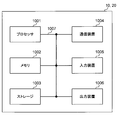
- FIG. 12 is a diagram showing an example of a hardware configuration of a radio base station and a user terminal according to an embodiment of the present invention.
- the above-described wireless base station 10 and user terminal 20 may be physically configured as a computer device including a processor 1001, a memory 1002, a storage 1003, a communication device 1004, an input device 1005, an output device 1006, a bus 1007 and the like. Good.
- the term “device” can be read as a circuit, a device, a unit, or the like.
- the hardware configuration of the radio base station 10 and the user terminal 20 may be configured to include one or more of the devices illustrated in the figure, or may be configured without including some devices.
- processor 1001 may be implemented by one or more chips.
- Each function in the radio base station 10 and the user terminal 20 is calculated by causing the processor 1001 to read predetermined software (program) on hardware such as the processor 1001 and the memory 1002, and the communication device 1004 is performed. This is realized by controlling communication, and controlling reading and / or writing of data in the memory 1002 and the storage 1003.
- the processor 1001 operates, for example, an operating system to control the entire computer.
- the processor 1001 may be configured by a central processing unit (CPU) including an interface with a peripheral device, a control device, an arithmetic device, a register, and the like.
- CPU central processing unit
- the above-described baseband signal processing unit 104 (204), call processing unit 105, and the like may be realized by the processor 1001.
- the processor 1001 reads a program (program code), a software module, data, and the like from the storage 1003 and / or the communication device 1004 to the memory 1002, and executes various processing according to these.
- a program a program that causes a computer to execute at least a part of the operations described in the above-described embodiment is used.
- the control unit 401 of the user terminal 20 may be realized by a control program stored in the memory 1002 and operating in the processor 1001, or may be realized similarly for other functional blocks.
- the memory 1002 is a computer readable recording medium, and for example, at least at least a read only memory (ROM), an erasable programmable ROM (EPROM), an electrically EPROM (EEPROM), a random access memory (RAM), or any other suitable storage medium. It may be configured by one.
- the memory 1002 may be called a register, a cache, a main memory (main storage device) or the like.
- the memory 1002 may store a program (program code), a software module, and the like that can be executed to implement the wireless communication method according to an embodiment of the present invention.
- the storage 1003 is a computer readable recording medium, and for example, a flexible disk, a floppy (registered trademark) disk, a magneto-optical disk (for example, a compact disk (CD-ROM (Compact Disc ROM), etc.), a digital versatile disk, Blu-ray® disc), removable disc, hard disc drive, smart card, flash memory device (eg card, stick, key drive), magnetic stripe, database, server, at least one other suitable storage medium May be configured by The storage 1003 may be called an auxiliary storage device.
- a computer readable recording medium for example, a flexible disk, a floppy (registered trademark) disk, a magneto-optical disk (for example, a compact disk (CD-ROM (Compact Disc ROM), etc.), a digital versatile disk, Blu-ray® disc), removable disc, hard disc drive, smart card, flash memory device (eg card, stick, key drive), magnetic stripe, database, server, at least one other suitable storage medium May be configured by
- the communication device 1004 is hardware (transmission / reception device) for performing communication between computers via a wired and / or wireless network, and is also called, for example, a network device, a network controller, a network card, a communication module, or the like.
- the communication device 1004 includes, for example, a high frequency switch, a duplexer, a filter, a frequency synthesizer, and the like to realize, for example, frequency division duplex (FDD) and / or time division duplex (TDD). It may be configured.
- FDD frequency division duplex
- TDD time division duplex
- the transmission / reception antenna 101 (201), the amplifier unit 102 (202), the transmission / reception unit 103 (203), the transmission path interface 106, and the like described above may be realized by the communication device 1004.
- the input device 1005 is an input device (for example, a keyboard, a mouse, a microphone, a switch, a button, a sensor, and the like) that receives an input from the outside.
- the output device 1006 is an output device (for example, a display, a speaker, a light emitting diode (LED) lamp, and the like) that performs output to the outside.
- the input device 1005 and the output device 1006 may be integrated (for example, a touch panel).
- each device such as the processor 1001 and the memory 1002 is connected by a bus 1007 for communicating information.
- the bus 1007 may be configured using a single bus, or may be configured using different buses between devices.
- radio base station 10 and the user terminal 20 may be microprocessors, digital signal processors (DSPs), application specific integrated circuits (ASICs), programmable logic devices (PLDs), field programmable gate arrays (FPGAs), etc.
- DSPs digital signal processors
- ASICs application specific integrated circuits
- PLDs programmable logic devices
- FPGAs field programmable gate arrays
- Hardware may be included, and part or all of each functional block may be realized using the hardware.
- processor 1001 may be implemented using at least one of these hardware.
- the channels and / or symbols may be signaling.
- the signal may be a message.
- the reference signal may be abbreviated as RS (Reference Signal), and may be referred to as a pilot (Pilot), a pilot signal or the like according to an applied standard.
- a component carrier CC: Component Carrier
- CC Component Carrier
- the radio frame may be configured by one or more periods (frames) in the time domain.
- Each of the one or more periods (frames) that constitute a radio frame may be referred to as a subframe.
- a subframe may be configured by one or more slots in the time domain.
- the subframes may be of a fixed time length (e.g., 1 ms) independent of the neurology.
- the slot may be configured by one or more symbols in the time domain (such as orthogonal frequency division multiplexing (OFDM) symbols, single carrier frequency division multiple access (SC-FDMA) symbols, etc.).
- the slot may be a time unit based on the neurology.
- the slot may include a plurality of minislots. Each minislot may be configured by one or more symbols in the time domain. Minislots may also be referred to as subslots.
- a radio frame, a subframe, a slot, a minislot and a symbol all represent time units when transmitting a signal.
- subframes, slots, minislots and symbols other names corresponding to each may be used.
- one subframe may be referred to as a transmission time interval (TTI)
- TTI transmission time interval
- a plurality of consecutive subframes may be referred to as a TTI
- one slot or one minislot may be referred to as a TTI.
- TTI transmission time interval
- the subframe and / or TTI may be a subframe (1 ms) in existing LTE, a period shorter than 1 ms (eg, 1-13 symbols), or a period longer than 1 ms. It may be.
- the unit representing TTI may be called a slot, a minislot, etc. instead of a subframe.
- TTI refers to, for example, the minimum time unit of scheduling in wireless communication.
- the radio base station performs scheduling to assign radio resources (frequency bandwidth usable in each user terminal, transmission power, etc.) to each user terminal in TTI units.
- radio resources frequency bandwidth usable in each user terminal, transmission power, etc.
- the TTI may be a transmission time unit of a channel encoded data packet (transport block), a code block, and / or a codeword, or may be a processing unit such as scheduling and link adaptation. Note that, when a TTI is given, the time interval (eg, the number of symbols) in which the transport block, the code block, and / or the codeword is actually mapped may be shorter than the TTI.
- one or more TTIs may be the minimum time unit of scheduling.
- the number of slots (the number of minislots) constituting the minimum time unit of the scheduling may be controlled.
- a TTI having a time length of 1 ms may be referred to as a normal TTI (TTI in LTE Rel. 8-12), a normal TTI, a long TTI, a normal subframe, a normal subframe, a long subframe, or the like.
- a TTI shorter than a normal TTI may be referred to as a shortened TTI, a short TTI, a partial TTI (partial or fractional TTI), a shortened subframe, a short subframe, a minislot, a subslot, or the like.
- a long TTI for example, a normal TTI, a subframe, etc.
- a short TTI eg, a shortened TTI, etc.
- a resource block is a resource allocation unit in time domain and frequency domain, and may include one or more consecutive subcarriers (subcarriers) in the frequency domain. Also, an RB may include one or more symbols in the time domain, and may be one slot, one minislot, one subframe, or one TTI in length. One TTI and one subframe may be respectively configured by one or more resource blocks. Note that one or more RBs may be a physical resource block (PRB: Physical RB), a subcarrier group (SCG: Sub-Carrier Group), a resource element group (REG: Resource Element Group), a PRB pair, an RB pair, etc. It may be called.
- PRB Physical resource block
- SCG Sub-Carrier Group
- REG Resource Element Group
- a resource block may be configured by one or more resource elements (RE: Resource Element).
- RE Resource Element
- one RE may be one subcarrier and one symbol radio resource region.
- the above-described structures such as the radio frame, subframe, slot, minislot and symbol are merely examples.
- the number of subframes included in a radio frame the number of slots per subframe or radio frame, the number of minislots included in a slot, the number of symbols and RBs included in a slot or minislot, included in an RB
- the number of subcarriers, as well as the number of symbols in a TTI, the symbol length, the cyclic prefix (CP) length, and other configurations can be variously changed.
- the information, parameters, etc. described in the present specification may be expressed using absolute values, may be expressed using relative values from predetermined values, or other corresponding information. May be represented.
- radio resources may be indicated by a predetermined index.
- the names used for parameters and the like in the present specification are not limited names in any respect.
- various channels PUCCH (Physical Uplink Control Channel), PDCCH (Physical Downlink Control Channel), etc.
- information elements can be identified by any suitable names, various assignments are made to these various channels and information elements.
- the name is not limited in any way.
- data, instructions, commands, information, signals, bits, symbols, chips etc may be voltage, current, electromagnetic waves, magnetic fields or particles, optical fields or photons, or any of these May be represented by a combination of
- information, signals, etc. may be output from the upper layer to the lower layer and / or from the lower layer to the upper layer.
- Information, signals, etc. may be input / output via a plurality of network nodes.
- the input / output information, signals and the like may be stored in a specific place (for example, a memory) or may be managed using a management table. Information, signals, etc. input and output can be overwritten, updated or added. The output information, signals and the like may be deleted. The input information, signals and the like may be transmitted to other devices.
- notification of information is not limited to the aspects / embodiments described herein, and may be performed using other methods.
- notification of information may be physical layer signaling (eg, downlink control information (DCI), uplink control information (UCI)), upper layer signaling (eg, RRC (Radio Resource Control) signaling, It may be implemented by broadcast information (Master Information Block (MIB), System Information Block (SIB), etc.), MAC (Medium Access Control) signaling, other signals, or a combination thereof.
- DCI downlink control information
- UCI uplink control information
- RRC Radio Resource Control
- MIB Master Information Block
- SIB System Information Block
- MAC Medium Access Control
- the physical layer signaling may be called L1 / L2 (Layer 1 / Layer 2) control information (L1 / L2 control signal), L1 control information (L1 control signal), or the like.
- RRC signaling may be referred to as an RRC message, and may be, for example, an RRC connection setup (RRC Connection Setup) message, an RRC connection reconfiguration (RRC Connection Reconfiguration) message, or the like.
- MAC signaling may be notified using, for example, a MAC control element (MAC CE (Control Element)).
- notification of predetermined information is not limited to explicit notification, but implicitly (for example, by not notifying the predetermined information or other information Notification may be performed).
- the determination may be performed by a value (0 or 1) represented by one bit, or may be performed by a boolean value represented by true or false. , Numerical comparison (for example, comparison with a predetermined value) may be performed.
- Software may be called software, firmware, middleware, microcode, hardware description language, or any other name, and may be instructions, instruction sets, codes, code segments, program codes, programs, subprograms, software modules. Should be interpreted broadly to mean applications, software applications, software packages, routines, subroutines, objects, executables, threads of execution, procedures, functions, etc.
- software, instructions, information, etc. may be sent and received via a transmission medium.
- software may use a wired technology (coaxial cable, fiber optic cable, twisted pair, digital subscriber line (DSL), etc.) and / or a wireless technology (infrared, microwave, etc.), a website, a server
- wired technology coaxial cable, fiber optic cable, twisted pair, digital subscriber line (DSL), etc.
- wireless technology infrared, microwave, etc.
- system and "network” as used herein are used interchangeably.
- base station Base Station
- radio base station eNB
- gNB gigad Generation
- cell cell
- cell group cell group
- carrier carrier
- carrier may be used interchangeably.
- a base station may also be called in terms of a fixed station (Node station), NodeB, eNodeB (eNB), access point (access point), transmission point, reception point, femtocell, small cell, and so on.
- a base station may accommodate one or more (e.g., three) cells (also called sectors). If the base station accommodates multiple cells, the entire coverage area of the base station can be partitioned into multiple smaller areas, each smaller area being a base station subsystem (eg, a small base station for indoor use (RRH: Communication service can also be provided by Remote Radio Head).
- RRH Communication service can also be provided by Remote Radio Head.
- the terms "cell” or “sector” refer to part or all of the coverage area of a base station and / or a base station subsystem serving communication services in this coverage.
- MS mobile station
- UE user equipment
- a base station may also be called in terms of a fixed station (Node station), NodeB, eNodeB (eNB), access point (access point), transmission point, reception point, femtocell, small cell, and so on.
- Node station Node station
- NodeB NodeB
- eNodeB eNodeB
- access point access point
- transmission point reception point
- femtocell small cell, and so on.
- the mobile station may be a subscriber station, a mobile unit, a subscriber unit, a wireless unit, a remote unit, a mobile device, a wireless device, a wireless communication device, a remote device, a mobile subscriber station, an access terminal, a mobile terminal, a wireless terminal, by those skilled in the art. It may also be called a terminal, a remote terminal, a handset, a user agent, a mobile client, a client or some other suitable term.
- the radio base station in the present specification may be replaced with a user terminal.
- each aspect / embodiment of the present invention may be applied to a configuration in which communication between a wireless base station and a user terminal is replaced with communication between a plurality of user terminals (D2D: Device-to-Device).
- the user terminal 20 may have a function that the above-described radio base station 10 has.
- the wordings such as "up” and “down” may be read as "side".
- the upstream channel may be read as a side channel.
- a user terminal herein may be read at a radio base station.
- the radio base station 10 may have a function that the above-described user terminal 20 has.
- the operation supposed to be performed by the base station may be performed by its upper node in some cases.
- various operations performed for communication with a terminal may be a base station, one or more network nodes other than the base station (eg, It is apparent that this can be performed by MME (Mobility Management Entity), S-GW (Serving-Gateway), etc. but not limited thereto or a combination thereof.
- MME Mobility Management Entity
- S-GW Serving-Gateway
- Each aspect / embodiment described in the present specification includes LTE (Long Term Evolution), LTE-A (LTE-Advanced), LTE-B (LTE-Beyond), SUPER 3G, IMT-Advanced, 4G (4th generation mobile) Communication system), 5G (5th generation mobile communication system), FRA (Future Radio Access), New-RAT (Radio Access Technology), NR (New Radio), NX (New radio access), FX (Future generation radio access), GSM (registered trademark) (Global System for Mobile communications), CDMA2000, UMB (Ultra Mobile Broadband), IEEE 802.11 (Wi-Fi (registered trademark)), IEEE 802.16 (WiMAX (registered trademark)), IEEE 802 .20, UWB (Ultra-Wide Band), Bluetooth (registered trademark) And / or systems based on other suitable wireless communication methods and / or extended next generation systems based on these.
- LTE Long Term Evolution
- LTE-A Long Term Evolution-Advanced
- any reference to an element using the designation "first”, “second” and the like as used herein does not generally limit the quantity or order of those elements. These designations may be used herein as a convenient way of distinguishing between two or more elements. Thus, reference to the first and second elements does not mean that only two elements can be taken or that the first element must somehow precede the second element.
- determining may encompass a wide variety of operations. For example, “determination” may be calculating, computing, processing, deriving, investigating, looking up (eg, table, database or other data) A search on structure), ascertaining, etc. may be considered as “determining”. Also, “determination” may be receiving (e.g. receiving information), transmitting (e.g. transmitting information), input (input), output (output), access (access) It may be considered as “determining” (eg, accessing data in memory) and the like. Also, “determination” is considered to be “determination” to resolve, select, choose, choose, establish, compare, etc. It is also good. That is, “determination” may be considered as “determining” some action.
- connection refers to any direct or indirect connection between two or more elements or It means a bond and can include the presence of one or more intermediate elements between two elements “connected” or “connected” to each other.
- the coupling or connection between elements may be physical, logical or a combination thereof. For example, “connection” may be read as "access”.
- the radio frequency domain It can be considered as “connected” or “coupled” with one another using electromagnetic energy or the like having wavelengths in the microwave region and / or the light (both visible and invisible) regions.
- a and B are different may mean “A and B are different from each other”.
- the terms “leave”, “combined” and the like may be interpreted similarly.
Abstract
Description
第1の態様における特定条件は、初期アクセス時にSSラスタ上で見つけたSSBにおいて、cellBarredがBarredであり、且つintraFreqReselectionがnot allowedであることである。 (First aspect)
The specific condition in the first aspect is that cellBarred is Barred and intraFreqReselection is not allowed in SSB found on the SS raster at the time of initial access.
第2の態様における特定条件は、コネクテッド(CONNECTEDモード)UEが、SSラスタ以外の周波数位置におけるSSBの測定(Measurement)を指示されることである。例えば、測定対象のSSBの周波数位置は、上位レイヤ(例えば、RRCシグナリングの情報要素メジャメントオブジェクト(measObject))を介して、指示される。 (Second aspect)
The specific condition in the second aspect is that the connected (CONNECTED mode) UE is instructed to measure SSB at frequency positions other than SS raster. For example, the frequency position of the SSB to be measured is indicated via the upper layer (for example, an information element measurement object (measObject) of RRC signaling).
第3の態様における特定条件は、コネクテッドUEが、SSBの測定を指示され、且つ上位レイヤによって設定される特定パラメータが測定値であることである。 (Third aspect)
The specific condition in the third aspect is that the connected UE is instructed to measure the SSB, and the specific parameter set by the upper layer is a measurement value.
第4の態様における特定条件は、コネクテッドUEが、特定周波数帯におけるSSBの測定を指示されたことであってもよい。例えば、特定周波数帯は、FR2であってもよい。 (Fourth aspect)
The specific condition in the fourth aspect may be that the connected UE is instructed to measure SSB in a specific frequency band. For example, the specific frequency band may be FR2.
PBCH内の情報要素のうち、上位レイヤによって通知できる情報であっても、PBCHによって通知されることが好ましい場合がある。 (Other aspects)
Among the information elements in the PBCH, it may be preferable to be notified by the PBCH even if the information can be notified by the upper layer.
以下、本発明の一実施形態に係る無線通信システムの構成について説明する。この無線通信システムでは、本発明の上記各実施形態に係る無線通信方法のいずれか又はこれらの組み合わせを用いて通信が行われる。 (Wireless communication system)
Hereinafter, the configuration of a wireless communication system according to an embodiment of the present invention will be described. In this wireless communication system, communication is performed using any one or a combination of the wireless communication methods according to the above embodiments of the present invention.
図8は、本発明の一実施形態に係る無線基地局の全体構成の一例を示す図である。無線基地局10は、複数の送受信アンテナ101と、アンプ部102と、送受信部103と、ベースバンド信号処理部104と、呼処理部105と、伝送路インターフェース106と、を備えている。なお、送受信アンテナ101、アンプ部102、送受信部103は、それぞれ1つ以上を含むように構成されればよい。 <Wireless base station>
FIG. 8 is a diagram showing an example of the entire configuration of a radio base station according to an embodiment of the present invention. The
図10は、本発明の一実施形態に係るユーザ端末の全体構成の一例を示す図である。ユーザ端末20は、複数の送受信アンテナ201と、アンプ部202と、送受信部203と、ベースバンド信号処理部204と、アプリケーション部205と、を備えている。なお、送受信アンテナ201、アンプ部202、送受信部203は、それぞれ1つ以上を含むように構成されればよい。 <User terminal>
FIG. 10 is a diagram showing an example of the entire configuration of a user terminal according to an embodiment of the present invention. The
なお、上記実施形態の説明に用いたブロック図は、機能単位のブロックを示している。これらの機能ブロック(構成部)は、ハードウェア及び/又はソフトウェアの任意の組み合わせによって実現される。また、各機能ブロックの実現方法は特に限定されない。すなわち、各機能ブロックは、物理的及び/又は論理的に結合した1つの装置を用いて実現されてもよいし、物理的及び/又は論理的に分離した2つ以上の装置を直接的及び/又は間接的に(例えば、有線及び/又は無線を用いて)接続し、これら複数の装置を用いて実現されてもよい。 <Hardware configuration>
The block diagram used for the explanation of the above-mentioned embodiment has shown the block of a functional unit. These functional blocks (components) are realized by any combination of hardware and / or software. Moreover, the implementation method of each functional block is not particularly limited. That is, each functional block may be realized using one physically and / or logically coupled device, or directly and / or two or more physically and / or logically separated devices. Or it may connect indirectly (for example, using a wire communication and / or radio), and it may be realized using a plurality of these devices.
なお、本明細書において説明した用語及び/又は本明細書の理解に必要な用語については、同一の又は類似する意味を有する用語と置き換えてもよい。例えば、チャネル及び/又はシンボルは信号(シグナリング)であってもよい。また、信号はメッセージであってもよい。参照信号は、RS(Reference Signal)と略称することもでき、適用される標準によってパイロット(Pilot)、パイロット信号などと呼ばれてもよい。また、コンポーネントキャリア(CC:Component Carrier)は、セル、周波数キャリア、キャリア周波数などと呼ばれてもよい。 (Modification)
The terms described in the present specification and / or the terms necessary for the understanding of the present specification may be replaced with terms having the same or similar meanings. For example, the channels and / or symbols may be signaling. Also, the signal may be a message. The reference signal may be abbreviated as RS (Reference Signal), and may be referred to as a pilot (Pilot), a pilot signal or the like according to an applied standard. Also, a component carrier (CC: Component Carrier) may be called a cell, a frequency carrier, a carrier frequency or the like.
Claims (6)
- ブロードキャストチャネルを含む同期信号ブロックをセルから受信する受信部と、
前記ブロードキャストチャネル内の特定情報要素を、特定条件が成立するか否かによって異なる情報要素として解釈する制御部と、を有することを特徴とするユーザ端末。 A receiver for receiving from the cell a synchronization signal block including a broadcast channel;
A user terminal, comprising: a control unit that interprets a specific information element in the broadcast channel as a different information element depending on whether a specific condition is satisfied. - 前記特定条件は、前記受信された同期信号ブロックが、初期アクセス用の同期信号ブロックを配置するために予め定義された複数の周波数位置の一つにおいて検出され、前記受信された同期信号ブロックが、前記受信された同期信号ブロックのキャリア帯域内にキャンプオン可能なセルがないことを示すことであり、
前記特定情報要素は、同期信号ブロックのサブキャリアオフセットに関する情報要素と、下り物理制御チャネルの構成に関する情報要素と、サブキャリア間隔に関する情報要素と、の少なくとも一部であることを特徴とする請求項1に記載のユーザ端末。 The specific condition is that the received synchronization signal block is detected at one of a plurality of predefined frequency positions for arranging a synchronization signal block for initial access, and the received synchronization signal block is Indicating that there is no campable cell in the carrier band of the received synchronization signal block,
The specific information element is at least a part of an information element on subcarrier offsets of a synchronization signal block, an information element on downlink physical control channel configuration, and an information element on subcarrier intervals. The user terminal according to 1. - 前記特定条件は、前記ユーザ端末がセルに接続された状態において、前記ユーザ端末が、初期アクセス用の同期信号ブロックを配置するために予め定義された複数の周波数位置以外の周波数位置における同期信号ブロックの測定を指示されることであり、
前記特定情報要素は、同期信号ブロックのサブキャリアオフセットに関する情報要素と、下り物理制御チャネルの構成に関する情報要素と、サブキャリア間隔に関する情報要素と、前記セルへのキャンプオン可能性に関する情報要素と、前記セルのキャリア帯域へのキャンプオン可能性に関する情報要素と、の少なくとも一部であることを特徴とする請求項1に記載のユーザ端末。 The specific condition is that, in a state where the user terminal is connected to a cell, the user terminal performs synchronization signal blocks at frequency positions other than a plurality of frequency positions defined in advance for arranging synchronization signal blocks for initial access. Be instructed to measure the
The specific information element includes an information element related to a subcarrier offset of a synchronization signal block, an information element related to the configuration of a downlink physical control channel, an information element related to a subcarrier interval, and an information element related to camp on possibility to the cell. The user terminal according to claim 1, wherein the user terminal is at least a part of an information element related to camp-on possibility to the carrier band of the cell. - 前記特定条件は、前記ユーザ端末がセルに接続された状態において、上位レイヤによって設定される特定パラメータが特定値であることであり、
前記特定情報要素は、同期信号ブロックのインデックスに関する情報要素の少なくとも一部であることを特徴とする請求項1に記載のユーザ端末。 The specific condition is that, in a state where the user terminal is connected to a cell, a specific parameter set by an upper layer is a specific value,
The user terminal according to claim 1, wherein the specific information element is at least a part of an information element related to an index of a synchronization signal block. - 前記特定条件が成立する場合、前記制御部は、前記特定情報要素を、サーチすべき同期信号ブロックの周波数位置に関する情報と、国番号及び/又はネットワーク番号に関する情報と、前記受信された同期信号ブロックのタイミングに関する情報と、前記受信された同期信号ブロックの測定に関する情報と、同期信号ブロックの間の擬似コロケーションに関する情報と、同期信号ブロックの集合の周期に関する情報と、の少なくとも一部として解釈することを特徴とする請求項1から請求項4のいずれかに記載のユーザ端末。 When the specific condition is satisfied, the control unit causes the specific information element to be information on a frequency position of a synchronization signal block to be searched, information on a country code and / or a network number, and the received synchronization signal block Interpreting at least a part of the information on the timing of the signal, the information on the measurement of the received synchronization signal block, the information on pseudo colocation between the synchronization signal blocks, and the information on the period of the set of synchronization signal blocks. The user terminal according to any one of claims 1 to 4, characterized by
- ブロードキャストチャネルを含む同期信号ブロックをセルから受信する工程と、
前記ブロードキャストチャネル内の特定情報要素を、特定条件が成立するか否かによって異なる情報要素として解釈する工程と、を有することを特徴とするユーザ端末の無線通信方法。 Receiving from the cell a synchronization signal block comprising a broadcast channel;
Interpreting a specific information element in the broadcast channel as a different information element depending on whether or not a specific condition is satisfied.
Priority Applications (8)
| Application Number | Priority Date | Filing Date | Title |
|---|---|---|---|
| EP17934851.1A EP3726879A4 (en) | 2017-12-13 | 2017-12-13 | User terminal and radio communication method |
| CN201780098260.9A CN111699714A (en) | 2017-12-13 | 2017-12-13 | User terminal and wireless communication method |
| US16/771,744 US11368874B2 (en) | 2017-12-13 | 2017-12-13 | Terminal and radio communication method |
| KR1020207017992A KR102423144B1 (en) | 2017-12-13 | 2017-12-13 | User terminal and wireless communication method |
| PCT/JP2017/044793 WO2019116477A1 (en) | 2017-12-13 | 2017-12-13 | User terminal and radio communication method |
| BR112020011708-0A BR112020011708A2 (en) | 2017-12-13 | 2017-12-13 | terminal, radiocommunication method for a terminal and base station |
| RU2020121806A RU2751550C1 (en) | 2017-12-13 | 2017-12-13 | User terminal and a radio communication method |
| JP2019559475A JP7092797B2 (en) | 2017-12-13 | 2017-12-13 | Terminals, wireless communication methods and systems |
Applications Claiming Priority (1)
| Application Number | Priority Date | Filing Date | Title |
|---|---|---|---|
| PCT/JP2017/044793 WO2019116477A1 (en) | 2017-12-13 | 2017-12-13 | User terminal and radio communication method |
Publications (1)
| Publication Number | Publication Date |
|---|---|
| WO2019116477A1 true WO2019116477A1 (en) | 2019-06-20 |
Family
ID=66819067
Family Applications (1)
| Application Number | Title | Priority Date | Filing Date |
|---|---|---|---|
| PCT/JP2017/044793 WO2019116477A1 (en) | 2017-12-13 | 2017-12-13 | User terminal and radio communication method |
Country Status (8)
| Country | Link |
|---|---|
| US (1) | US11368874B2 (en) |
| EP (1) | EP3726879A4 (en) |
| JP (1) | JP7092797B2 (en) |
| KR (1) | KR102423144B1 (en) |
| CN (1) | CN111699714A (en) |
| BR (1) | BR112020011708A2 (en) |
| RU (1) | RU2751550C1 (en) |
| WO (1) | WO2019116477A1 (en) |
Cited By (5)
| Publication number | Priority date | Publication date | Assignee | Title |
|---|---|---|---|---|
| WO2021019695A1 (en) * | 2019-07-30 | 2021-02-04 | 株式会社Nttドコモ | Terminal |
| WO2021217503A1 (en) * | 2020-04-29 | 2021-11-04 | Lenovo (Beijing) Limited | Method and apparatus for initial access of a ue |
| WO2022021225A1 (en) * | 2020-07-30 | 2022-02-03 | Oppo广东移动通信有限公司 | Wireless communication method, terminal device, and network device |
| US20220104157A1 (en) * | 2019-11-12 | 2022-03-31 | Guangdong Oppo Mobile Telecommunications Corp., Ltd. | Wireless communication method, network device, and terminal device |
| US20220279553A1 (en) * | 2019-07-09 | 2022-09-01 | Beijing Xiaomi Mobile Software Co., Ltd. | Method and apparatus for information processing |
Families Citing this family (19)
| Publication number | Priority date | Publication date | Assignee | Title |
|---|---|---|---|---|
| CN110365461B (en) * | 2017-12-18 | 2020-08-07 | 华为技术有限公司 | Signal sending and receiving method and equipment |
| CA3087974A1 (en) | 2018-01-11 | 2019-07-18 | Ntt Docomo, Inc. | User terminal and radio communication method |
| JP2019140512A (en) * | 2018-02-09 | 2019-08-22 | シャープ株式会社 | Terminal device, base station device, and communication method |
| CN110149676B (en) * | 2018-02-11 | 2022-03-25 | 华为技术有限公司 | Method and device for selecting resident cell |
| EP4344334A2 (en) * | 2018-02-13 | 2024-03-27 | Samsung Electronics Co., Ltd. | Method and device for communicating synchronization signal |
| KR20200111815A (en) | 2018-02-14 | 2020-09-29 | 광동 오포 모바일 텔레커뮤니케이션즈 코포레이션 리미티드 | Instruction method, detection method and related device |
| US11160050B2 (en) | 2018-03-28 | 2021-10-26 | Samsung Electronics Co., Ltd. | Method and apparatus for supporting large subcarrier spacing for SS/PBCH block |
| US20190393980A1 (en) * | 2018-06-22 | 2019-12-26 | Mediatek Inc. | Method for NR Radio Link Monitoring (RLM) and Evaluation Period Determination |
| US11399356B2 (en) * | 2018-06-26 | 2022-07-26 | Qualcomm Incorporated | Synchronization signal block (SSB)-based positioning measurement signals |
| CN110719603B (en) * | 2018-07-12 | 2023-05-09 | 中国移动通信有限公司研究院 | Measurement method of connection state synchronous signal block and network unit |
| CA3111645C (en) * | 2018-09-18 | 2023-04-18 | Guangdong Oppo Mobile Telecommunications Corp., Ltd. | Synchronization signal transmission method, transmitting end device and receiving end device |
| CN111083784B (en) * | 2018-10-22 | 2022-07-01 | 上海朗帛通信技术有限公司 | Method and device used in node of wireless communication |
| WO2020090094A1 (en) * | 2018-11-01 | 2020-05-07 | 株式会社Nttドコモ | Radio node and radio communication method |
| CN110535545A (en) * | 2019-01-11 | 2019-12-03 | 中兴通讯股份有限公司 | A kind of information determines method and apparatus, the treating method and apparatus of information element |
| WO2020235457A1 (en) * | 2019-05-17 | 2020-11-26 | 株式会社Nttドコモ | User terminal and wireless communication method |
| US20210051485A1 (en) * | 2019-08-16 | 2021-02-18 | Mediatek Inc. | Radio resource management (rrm) procedure in a shared spectrum |
| CN112469122A (en) * | 2020-10-15 | 2021-03-09 | 中国信息通信研究院 | Broadcast channel indication method, equipment and communication system |
| CN112312331B (en) * | 2020-10-20 | 2022-07-08 | 捷开通讯(深圳)有限公司 | Physical broadcast channel and information transmission method and device |
| BR112023020560A2 (en) * | 2021-04-06 | 2023-12-05 | Ericsson Telefon Ab L M | SIGNALING A NEARLY COLOCALIZED RELATIONSHIP (QCL) |
Citations (1)
| Publication number | Priority date | Publication date | Assignee | Title |
|---|---|---|---|---|
| WO2017078091A1 (en) * | 2015-11-05 | 2017-05-11 | 株式会社Nttドコモ | User device, wireless base station, and wireless communication method |
Family Cites Families (14)
| Publication number | Priority date | Publication date | Assignee | Title |
|---|---|---|---|---|
| US8335176B2 (en) * | 2008-04-07 | 2012-12-18 | Qualcomm Incorporated | Transmission of overhead channels with timing offset and blanking |
| KR102058999B1 (en) * | 2012-02-21 | 2019-12-24 | 엘지전자 주식회사 | Initial access method and device in wireless communication system |
| JP6392792B2 (en) * | 2013-03-17 | 2018-09-19 | エルジー エレクトロニクス インコーポレイティド | Broadcast channel assignment method, broadcast channel signal transmission / reception method, and apparatus supporting these methods |
| WO2014205798A1 (en) * | 2013-06-28 | 2014-12-31 | 华为技术有限公司 | Determination method and transmission method for system frame number, and related device |
| EP3783941B1 (en) | 2014-03-19 | 2024-02-21 | InterDigital Patent Holdings, Inc. | Method and apparatus for system information block (sib) acquisition for wireless transmit/receive units (wtrus) in non-ce and coverage enhanced (ce) modes |
| US11212760B2 (en) * | 2015-09-24 | 2021-12-28 | Qualcomm Incorporated | Common synchronization channel design for narrowband communications |
| WO2017054161A1 (en) | 2015-09-30 | 2017-04-06 | 华为技术有限公司 | Channel transmission method and base station, and user equipment |
| WO2017160048A2 (en) * | 2016-03-14 | 2017-09-21 | Samsung Electronics Co., Ltd. | Method and apparatus for synchronization operation in cellular internet of things networks |
| EP3410625B1 (en) * | 2016-03-16 | 2020-08-26 | LG Electronics Inc. | Techniques for transmission and reception of control information in a wireless communication system |
| ES2910793T3 (en) * | 2017-03-28 | 2022-05-13 | Beijing Xiaomi Mobile Software Co Ltd | Method and apparatus for transmitting and acquiring synchronization information block |
| RU2738925C1 (en) * | 2017-05-05 | 2020-12-18 | ЭлДжи ЭЛЕКТРОНИКС ИНК. | Method of receiving a synchronization signal and a corresponding device |
| KR101956038B1 (en) * | 2017-06-04 | 2019-03-08 | 엘지전자 주식회사 | The method and apparatus for receiving system information in the wireless communication |
| GB2563454A (en) * | 2017-06-16 | 2018-12-19 | Nec Corp | Communication system |
| CN110603852B (en) * | 2017-11-17 | 2021-10-08 | Lg电子株式会社 | Method for transmitting and receiving downlink channel and apparatus therefor |
-
2017
- 2017-12-13 WO PCT/JP2017/044793 patent/WO2019116477A1/en active Application Filing
- 2017-12-13 RU RU2020121806A patent/RU2751550C1/en active
- 2017-12-13 JP JP2019559475A patent/JP7092797B2/en active Active
- 2017-12-13 EP EP17934851.1A patent/EP3726879A4/en active Pending
- 2017-12-13 BR BR112020011708-0A patent/BR112020011708A2/en unknown
- 2017-12-13 KR KR1020207017992A patent/KR102423144B1/en active IP Right Grant
- 2017-12-13 US US16/771,744 patent/US11368874B2/en active Active
- 2017-12-13 CN CN201780098260.9A patent/CN111699714A/en active Pending
Patent Citations (1)
| Publication number | Priority date | Publication date | Assignee | Title |
|---|---|---|---|---|
| WO2017078091A1 (en) * | 2015-11-05 | 2017-05-11 | 株式会社Nttドコモ | User device, wireless base station, and wireless communication method |
Non-Patent Citations (3)
| Title |
|---|
| "Evolved Universal Terrestrial Radio Access (E-UTRA) and Evolved Universal Terrestrial Radio Access Network (E-UTRAN); Overall Description; Stage 2", 3GPP TS 36.300 |
| SAMSUNG: "Remaining aspects of PBCH and some SIB1 contents", 3GPP TSG-RAN WG2 99BIS MEETING, R2-1711743, 13 October 2017 (2017-10-13), XP051343699, Retrieved from the Internet <URL:http://www.3gpp.org/ftp/TSG_RAN/WG2_RL2/99bis/Docs/R2-1711743.zip> [retrieved on 20180205] * |
| See also references of EP3726879A4 |
Cited By (6)
| Publication number | Priority date | Publication date | Assignee | Title |
|---|---|---|---|---|
| US20220279553A1 (en) * | 2019-07-09 | 2022-09-01 | Beijing Xiaomi Mobile Software Co., Ltd. | Method and apparatus for information processing |
| WO2021019695A1 (en) * | 2019-07-30 | 2021-02-04 | 株式会社Nttドコモ | Terminal |
| US20220104157A1 (en) * | 2019-11-12 | 2022-03-31 | Guangdong Oppo Mobile Telecommunications Corp., Ltd. | Wireless communication method, network device, and terminal device |
| EP4236474A3 (en) * | 2019-11-12 | 2023-10-11 | Guangdong Oppo Mobile Telecommunications Corp., Ltd. | Wireless communication method, network device, and terminal device |
| WO2021217503A1 (en) * | 2020-04-29 | 2021-11-04 | Lenovo (Beijing) Limited | Method and apparatus for initial access of a ue |
| WO2022021225A1 (en) * | 2020-07-30 | 2022-02-03 | Oppo广东移动通信有限公司 | Wireless communication method, terminal device, and network device |
Also Published As
| Publication number | Publication date |
|---|---|
| US11368874B2 (en) | 2022-06-21 |
| KR20200092992A (en) | 2020-08-04 |
| KR102423144B1 (en) | 2022-07-21 |
| RU2751550C1 (en) | 2021-07-14 |
| CN111699714A (en) | 2020-09-22 |
| EP3726879A1 (en) | 2020-10-21 |
| JP7092797B2 (en) | 2022-06-28 |
| US20200404537A1 (en) | 2020-12-24 |
| JPWO2019116477A1 (en) | 2020-12-10 |
| EP3726879A4 (en) | 2021-07-21 |
| BR112020011708A2 (en) | 2020-11-17 |
Similar Documents
| Publication | Publication Date | Title |
|---|---|---|
| JP7092797B2 (en) | Terminals, wireless communication methods and systems | |
| JP7337696B2 (en) | Terminal, wireless communication method, base station and system | |
| CN110574432B (en) | User terminal and wireless communication method | |
| CN110603864B (en) | User terminal and wireless communication method | |
| CN111630916A (en) | User terminal and wireless communication method | |
| WO2019111862A1 (en) | User terminal and wireless communication method | |
| JP7379630B2 (en) | Terminals, wireless communication methods, base stations and systems | |
| WO2019069471A1 (en) | User terminal and wireless communication method | |
| WO2019159291A1 (en) | User terminal and wireless communications method | |
| CN112789808A (en) | User terminal and wireless communication method | |
| US11240770B2 (en) | Terminal and radio communication method | |
| US20200145854A1 (en) | User terminal and radio communication method | |
| US11751149B2 (en) | User terminal and radio communication method | |
| CN113039862A (en) | Wireless communication device and wireless communication method | |
| JPWO2018062455A1 (en) | User terminal and wireless communication method | |
| CN110870340A (en) | User terminal and wireless communication method | |
| WO2019073862A1 (en) | User equipment, base station and wireless communication method |
Legal Events
| Date | Code | Title | Description |
|---|---|---|---|
| 121 | Ep: the epo has been informed by wipo that ep was designated in this application |
Ref document number: 17934851 Country of ref document: EP Kind code of ref document: A1 |
|
| WWE | Wipo information: entry into national phase |
Ref document number: 2019559475 Country of ref document: JP |
|
| NENP | Non-entry into the national phase |
Ref country code: DE |
|
| ENP | Entry into the national phase |
Ref document number: 20207017992 Country of ref document: KR Kind code of ref document: A |
|
| ENP | Entry into the national phase |
Ref document number: 2017934851 Country of ref document: EP Effective date: 20200713 |
|
| REG | Reference to national code |
Ref country code: BR Ref legal event code: B01A Ref document number: 112020011708 Country of ref document: BR |
|
| ENP | Entry into the national phase |
Ref document number: 112020011708 Country of ref document: BR Kind code of ref document: A2 Effective date: 20200610 |