WO2019159291A1 - User terminal and wireless communications method - Google Patents
User terminal and wireless communications method Download PDFInfo
- Publication number
- WO2019159291A1 WO2019159291A1 PCT/JP2018/005334 JP2018005334W WO2019159291A1 WO 2019159291 A1 WO2019159291 A1 WO 2019159291A1 JP 2018005334 W JP2018005334 W JP 2018005334W WO 2019159291 A1 WO2019159291 A1 WO 2019159291A1
- Authority
- WO
- WIPO (PCT)
- Prior art keywords
- information
- group
- transmission
- ssb
- transmitted
- Prior art date
Links
Images


Classifications
-
- H—ELECTRICITY
- H04—ELECTRIC COMMUNICATION TECHNIQUE
- H04L—TRANSMISSION OF DIGITAL INFORMATION, e.g. TELEGRAPHIC COMMUNICATION
- H04L5/00—Arrangements affording multiple use of the transmission path
- H04L5/003—Arrangements for allocating sub-channels of the transmission path
- H04L5/0048—Allocation of pilot signals, i.e. of signals known to the receiver
- H04L5/005—Allocation of pilot signals, i.e. of signals known to the receiver of common pilots, i.e. pilots destined for multiple users or terminals
-
- H—ELECTRICITY
- H04—ELECTRIC COMMUNICATION TECHNIQUE
- H04W—WIRELESS COMMUNICATION NETWORKS
- H04W72/00—Local resource management
- H04W72/30—Resource management for broadcast services
-
- H—ELECTRICITY
- H04—ELECTRIC COMMUNICATION TECHNIQUE
- H04L—TRANSMISSION OF DIGITAL INFORMATION, e.g. TELEGRAPHIC COMMUNICATION
- H04L27/00—Modulated-carrier systems
- H04L27/26—Systems using multi-frequency codes
- H04L27/2601—Multicarrier modulation systems
- H04L27/2602—Signal structure
- H04L27/261—Details of reference signals
-
- H—ELECTRICITY
- H04—ELECTRIC COMMUNICATION TECHNIQUE
- H04L—TRANSMISSION OF DIGITAL INFORMATION, e.g. TELEGRAPHIC COMMUNICATION
- H04L5/00—Arrangements affording multiple use of the transmission path
- H04L5/0091—Signaling for the administration of the divided path
- H04L5/0094—Indication of how sub-channels of the path are allocated
-
- H—ELECTRICITY
- H04—ELECTRIC COMMUNICATION TECHNIQUE
- H04W—WIRELESS COMMUNICATION NETWORKS
- H04W56/00—Synchronisation arrangements
- H04W56/001—Synchronization between nodes
-
- H—ELECTRICITY
- H04—ELECTRIC COMMUNICATION TECHNIQUE
- H04W—WIRELESS COMMUNICATION NETWORKS
- H04W72/00—Local resource management
- H04W72/20—Control channels or signalling for resource management
- H04W72/23—Control channels or signalling for resource management in the downlink direction of a wireless link, i.e. towards a terminal
-
- H—ELECTRICITY
- H04—ELECTRIC COMMUNICATION TECHNIQUE
- H04B—TRANSMISSION
- H04B7/00—Radio transmission systems, i.e. using radiation field
- H04B7/02—Diversity systems; Multi-antenna system, i.e. transmission or reception using multiple antennas
- H04B7/04—Diversity systems; Multi-antenna system, i.e. transmission or reception using multiple antennas using two or more spaced independent antennas
- H04B7/06—Diversity systems; Multi-antenna system, i.e. transmission or reception using multiple antennas using two or more spaced independent antennas at the transmitting station
- H04B7/0686—Hybrid systems, i.e. switching and simultaneous transmission
- H04B7/0695—Hybrid systems, i.e. switching and simultaneous transmission using beam selection
Definitions
- the present invention relates to a user terminal and a wireless communication method in a next generation mobile communication system.
- LTE Long Term Evolution
- Non-patent Document 1 LTE Advanced, LTE Rel. 10, 11, 12, 13
- LTE Rel. 8, 9 LTE Advanced, LTE Rel. 10, 11, 12, 13
- LTE successor systems for example, FRA (Future Radio Access), 5G (5th generation mobile communication system), 5G + (plus), NR (New Radio), NX (New radio access), FX (Future generation radio access), LTE Also referred to as Rel.
- a user terminal (UE: User Equipment) is synchronized with a synchronization signal (PSS (Primary Synchronization Signal) by an initial access procedure (also called a cell search or the like). And / or SSS (Secondary Synchronization Signal) is detected and synchronized with a network (for example, a radio base station (eNB (eNode B))) and connected cells are identified (for example, a cell ID (Identifier)). Identified by).
- PSS Primary Synchronization Signal
- a network for example, a radio base station (eNB (eNode B)
- eNB radio base station
- connected cells for example, a cell ID (Identifier)). Identified by).
- the UE transmits a master information block (MIB) transmitted on a broadcast channel (PBCH: Physical Broadcast Channel) and a downlink (DL) shared channel (PDSCH: Physical Downlink Shared Channel).
- MIB Master information block
- PBCH Physical Broadcast Channel
- PDSCH Physical Downlink Shared Channel
- SIB System Information Block
- E-UTRA Evolved Universal Terrestrial Radio Access
- E-UTRAN Evolved Universal Terrestrial Radio Access Network
- a resource unit including a synchronization signal and a broadcast channel is defined as a synchronization signal block and an initial connection is performed based on the SS block.
- the synchronization signal is also referred to as PSS and / or SSS, or NR-PSS and / or NR-SSS.
- the broadcast channel is also called PBCH or NR-PBCH.
- the synchronization signal block is also called an SS block (Synchronization Signal block: SSB) or an SS / PBCH block.
- the user terminal needs to recognize the resource to which the SS block is transmitted. However, since the amount of information for notifying the resource to which the SS block is transmitted is limited, the user terminal may not be able to recognize the resource correctly.
- An advantage of some aspects of the invention is that it provides a user terminal and a wireless communication method that appropriately notify a resource to which a synchronization signal block is transmitted in a future wireless communication system. .
- a user terminal includes pattern information indicating whether or not a synchronization signal block is transmitted at each of a plurality of transmission candidate positions in a group of transmission signal candidate positions of a synchronization signal block, A receiving unit that receives group information indicating a method of applying the pattern information to each of the receiving unit, and assuming that a synchronization signal block is transmitted at all transmission candidate positions in the specific group; And a control unit that controls one of the transmission candidate positions based on the group information.
- 1A and 1B are diagrams illustrating an example of an SS burst set. It is a figure which shows an example of the transmission candidate position of SSB. It is a figure which shows an example of the notification method of real transmission SSB. It is a figure which shows an example of a TDD DL / UL structure.
- 5A and 5B are diagrams illustrating an example of a RACH configuration setting method.
- 6A and 6B are diagrams illustrating an example of an arrangement of actual transmission SSBs that can be signaled by RMSI and an example of an arrangement of actual transmission SSBs that cannot be signaled by RMSI. It is a figure which shows an example of the real transmission SSB which concerns on a 1st aspect.
- synchronization signals also referred to as SS, PSS and / or SSS, or NR-PSS and / or NR-SSS, etc.
- broadcast It has been studied to define a signal block (also referred to as SS / PBCH block, SS / PBCH block or the like) including a channel (also referred to as a broadcast signal, PBCH, or NR-PBCH).
- a set of one or more signal blocks is also called a signal burst (SS / PBCH burst or SS burst).
- a plurality of signal blocks in the signal burst are transmitted with different beams at different times (also referred to as beam sweep).
- the SS / PBCH block is composed of one or more symbols (for example, OFDM symbols). Specifically, the SS / PBCH block may be composed of a plurality of consecutive symbols. In the SS / PBCH block, PSS, SSS, and NR-PBCH may be arranged in one or more different symbols. For example, it is considered that the SS / PBCH block is composed of 4 or 5 symbols including 1 symbol PSS, 1 symbol SSS, 2 or 3 symbols PBCH.
- a set of one or more SS / PBCH blocks may be referred to as an SS / PBCH burst.
- the SS / PBCH burst may be composed of SS / PBCH blocks in which frequency and / or time resources are continuous, or may be composed of SS / PBCH blocks in which frequency and / or time resources are discontinuous.
- the SS / PBCH burst may be set with a predetermined period (may be referred to as an SS / PBCH burst period), or may be set with a non-period.
- one or more SS / PBCH bursts may be referred to as an SS / PBCH burst set (SS / PBCH burst series).
- the SS / PBCH burst set is set periodically.
- the user terminal may control the reception process on the assumption that the SS / PBCH burst set is transmitted periodically (with SS / PBCH burst set period (SS burst set periodicity)).
- FIG. 1 is a diagram showing an example of an SS burst set.
- a radio base station eg, gNB
- gNB radio base station
- FIG. 1A and 1B show an example using a multi-beam, but it is also possible to transmit an SS block using a single beam.
- an SS burst is composed of one or more SS blocks
- an SS burst set is composed of one or more SS bursts.
- the SS burst is composed of 8SS blocks # 0 to # 7, but the present invention is not limited to this.
- SS blocks # 0 to # 7 may be transmitted by different beams # 0 to # 7 (FIG. 1A).
- an SS burst set including SS blocks # 0 to # 7 may be transmitted so as not to exceed a predetermined period (for example, 5 ms or less, also referred to as an SS burst set period). Further, the SS burst set may be repeated at a predetermined cycle (for example, 5, 10, 20, 40, 80, or 160 ms, also referred to as an SS burst set cycle).
- a predetermined period for example, 5 ms or less, also referred to as an SS burst set period
- the SS burst set may be repeated at a predetermined cycle (for example, 5, 10, 20, 40, 80, or 160 ms, also referred to as an SS burst set cycle).
- a predetermined time interval between SS blocks # 1 and # 2, # 3 and # 4, # 5 and # 6, but this time interval may not be present, and between other SS blocks. (For example, between SS blocks # 2 and # 3, # 5 and # 6, etc.) may be provided.
- a DL control channel (PDCCH, NR-PDCCH, or downlink control information (DCI)) may be transmitted and / or a UL control channel (PUCCH).
- PUCCH Physical Uplink Control Channel
- a slot of 14 symbols may include 2 symbols of PDCCH, 2 SS blocks, 2 symbols of PUCCH, and guard time.
- the SS block index (SS block index) is notified using PBCH and / or DMB (DeModulation Reference Signal) (PBCH DMRS) for PBCH included in the SS block.
- PBCH DMRS DeModulation Reference Signal
- the UE can grasp the SS block index of the received SS block based on the PBCH (or PBCH DMRS).
- MIB Master Information Block
- MSI Minimum System Information
- RMSI Remaining Minimum System Information
- SIB System Information Block 1 and SIB 2 in LTE.
- RMSI Remaining Minimum System Information
- an SS block may be used for synchronization, cell detection, frame and / or slot timing detection, and the like.
- a plurality of SSBs within a 5 ms SSB transmission period indicate the same cell ID.
- Each SSB indicates a unique SSB index.
- the SSB index determines the time position (transmission candidate position) of the SSB within the SSB transmission period.
- the maximum number L of SSBs that can be transmitted within one SSB transmission period may be determined according to the frequency band.
- L in the frequency band of 0-3 GHz may be 4
- L in the frequency band of 3-6 GHz may be 8
- L in the frequency band of 6-52.6 GHz may be 64.
- the SSB transmission period may be set to one of 5, 10, 20, 40, 80, and 160 ms.
- the frequency band lower than 6 GHz may be referred to as sub-6, FR (Frequency Range) 1.
- a frequency band higher than 6 GHz may be referred to as above-6, FR2, millimeter wave, etc., or may refer to a frequency band higher than 24 GHz.
- SSB transmission candidate positions within an SSB transmission period (for example, 5 ms) may be defined by specifications.
- the SSB transmission period may be a 5 ms half frame in the first half or the second half of the radio frame.
- 64 SSB transmission candidate positions may be defined for a frequency band of 6 GHz or more and a subcarrier spacing (SCS) of 120 kHz.
- SCS subcarrier spacing
- the SSB transmission candidate position may be represented by an SSB index in the time direction.
- the radio base station may transmit an arbitrary number of L or less SSBs every SSB transmission cycle.
- the radio base station may notify the UE of actually transmitted SSB (actually transmitted SSB) using a bitmap.
- the UE only needs to be able to detect one SSB in synchronization, cell detection, frame and / or slot timing detection, and the like. On the other hand, in rate matching and measurement, the UE can accurately perform rate matching and measurement by recognizing the actual transmission SSB.
- the intra-burst SSB position information is included in the RMSI.
- the intra-burst SSB position information includes two information elements, an intra-group bitmap (InOneGroup, bitmap in group), and a group bitmap (groupPresence).
- the intra-group bitmap indicates whether or not an SSB at each transmission candidate position in the group is transmitted.
- the group bitmap indicates whether each group in the SSB transmission period is applied.
- the UE having the initial access can read the SSB location information in the burst.
- In-burst SSB position information for example, ssb-PositionsInBurst
- serving cell configuration common information for example, ServingCellConfigCommon
- the serving cell configuration common information is an information element notified to a connected UE (connected UE) by RRC signaling.
- the intra-burst SSB position information is included in the serving cell configuration common information and indicates the actual transmission SSB in the serving cell (carrier).
- the UE can perform rate matching around the actual transmission SSB in the allocated data based on the intra-burst SSB position information.
- the intra-burst SSB position information may include a bit for each transmission candidate position of the actual transmission SSB.
- the presence / absence of actual transmission SSBs at 64 transmission candidate positions may be supported using a bit map (full bit map) of up to 64 bits.
- SSB information for example, SSB-ToMeasure
- SMTC SS / PBCH block based measurement timing configuration
- the SMTC information is an information element included in a measurement instruction (for example, measurement object) notified to a connected UE (connected UE) by RRC signaling.
- the SSB information for measurement is included in the SMTC information and indicates which SSB is assumed as a measurement target by a full bitmap.
- the measurement SSB information indicates the actual transmission SSB of not only the serving cell but also the neighboring cells using the same frequency.
- the actual transmission SSB indicated by the measurement SSB information is a superset of the actual transmission SSB in the serving cell and the neighboring cells.
- the bit of the SSB transmitted in at least one of the serving cell and the neighboring cell indicates ON.
- the UE can measure the serving cell and the neighboring cells without omission by using the SSB information for measurement. Further, the measurement load of the UE can be suppressed by indicating that the SSB bit that is not transmitted in any of the serving cell and the neighboring cell is OFF.
- the in-burst SSB position information in the serving cell configuration common information and the measurement SSB information in the SMTC information are notified by RRC signaling, and therefore, the size (overhead) is less restricted than the RMSI.
- a full bitmap can be used.
- the intra-burst SSB position information in the RMSI is notified by the RMSI, so the size (overhead) is severely restricted.
- In-group bitmap and group bitmap are used.
- the intra-group bitmap is 8 bits and the group bitmap is 8 bits.
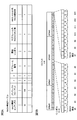
- FIG. 2 is a diagram illustrating an example of SSB transmission candidate positions when a 120 kHz SCS and a 20 ms SSB transmission period of 20 ms are used in a frequency band of 6 GHz or higher.
- 64 transmission candidate positions within the SSB transmission period may be defined by the specification.
- the first 8 slots include transmission candidate positions, and the last 2 slots do not include transmission candidate positions. These two slots are reserved for use in the UL.
- Each slot of the first 8 slots includes two transmission candidate positions.
- the length of one transmission candidate position is 4 symbols.
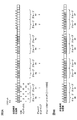
- the intra-group bitmap pattern is applied to the group having the bit 1, and the actual transmission SSB is not included in the group having the bit 0. It shows that.
- the UE determines the presence / absence of the actual transmission SSB in the group whose bit is 1 according to the intra-group bitmap, and interprets that there is no actual transmission SSB in the group whose bit is 0.
- the bits of groups # 0 to # 5 are 1, and the bits of groups # 6 and # 7 are 0.
- the SSB is transmitted at the transmission candidate position where the bit is 1, and the SSB is not transmitted at the transmission candidate position where the bit is 0. Indicates.
- the bits at all the transmission candidate positions are 1.
- the TDD DL / UL configuration in the TDD carrier may be notified semi-statically (via RRC signaling or RMSI) to the UE or dynamically (via DCI).
- the TDD DL / UL configuration may be notified semi-statically and dynamically changed.
- the TDD DL / UL configuration when the TDD DL / UL configuration is set semi-statically, one or two patterns indicating DL (DL part), flexible, or UL (UL part) are given cycles. (Period) may be set specific to a cell.
- any pattern indicating DL, flexible, or UL for each slot may be set UE-specific for a given period (period). .
- the period may be one of 0.5, 0.625, 1, 1.25, 2, 2.5, 5, 10 ms.
- RACH Random Access Channel or Physical Random Access Channel: PRACH
- PRACH configuration table for initial access is being studied.
- the RACH configuration table has a plurality of entries. Each entry indicates a RACH configuration (RACH opportunity).
- One entry includes a RACH configuration index, a preamble (PRACH) format, a RACH opportunity SFN condition (x and y), a RACH opportunity subframe number, a RACH opportunity start symbol, the number of RACH slots in the subframe, and a RACH slot. May include the number of RACH opportunities.
- the number of RACH slots in the subframe is 1 if the SCS is 15 kHz, or 1 or 2 if the SCS is 30 kHz.
- This example shows a RACH configuration table for a frequency band of 6 GHz or less, but a similar RACH configuration table may be used in a frequency band of 6 GHz or more.
- the one RACH configuration in the RACH configuration table may be notified to the UE by specifying the RMSI configuration index by the RMSI or the like.
- the UE can recognize the preamble format and RACH resources (time and frequency location, period, association between SSB and RACH resources) that can be used in the cell. If multiple SSBs are respectively transmitted using multiple beams, the UE can recognize the beams for SSB and / or RACH.
- the cell corresponding to the stand-alone may notify the following information by RMSI to the initial access UE.
- Actual transmission SSB for example, combination of group bitmap and intra-group bitmap
- RACH configuration eg, RACH configuration index
- the actual transmission SSB notified by the RMSI specifies one pattern of ON / OFF for eight consecutive SSBs in the group, and the pattern is applied to each group or all SSBs are OFF. Or set. Considering the periodic TDD DL / UL configuration, there may be cases where patterns do not match between groups.
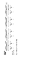
- FIG. 6A shows an arrangement of actual transmission SSBs that can be signaled by RMSI.
- the group bitmap is 11111100 and the intragroup bitmap is 111100.
- Group # 0 includes SSB # 0- # 7, and group # 1 includes SSB # 8- # 15. According to the group bitmap and the intra-group bitmap, SSBs # 0 to # 5 and # 8 to # 13 are transmitted (ON), and SSBs # 6, # 7, # 14, and # 15 are not transmitted (OFF).
- FIG. 6B shows an arrangement of actual transmission SSBs that cannot be signaled by RMSI.
- the intra-group bitmap corresponding to groups # 0, # 2, # 4, and # 6 is 11111111
- the intra-group bitmap corresponding to groups # 1, # 3, # 5, and # 7 is 11111100. Therefore, since the intra-group bitmaps do not match between groups, such an actual transmission SSB cannot be correctly notified by the RMSI (group bitmap and intra-group bitmap).
- the actual transmission SSB information includes an 8-bit group bitmap and an 8-bit intra-group bitmap, and the UE does not apply the intra-group bitmap pattern (the corresponding bit in the group bitmap is A method for interpreting that all SSBs in the group are off for a group (which is 0) is called an existing notification method.
- the UE associates the actual transmission SSB notified by the actual transmission SSB information with the RACH opportunity specified by the RACH configuration index.
- the UE associates the RACH opportunity in time order with the actual transmission SSB in order of SSB index.
- RACH opportunities that are not linked to actual transmission SSBs may be used for other purposes.
- the UE associates SSB # 0 to # 5 and # 8 with RACH opportunity # 0 to # 6, respectively.
- the UE sets the SSB # 1 to the RACH opportunities # 0 to # 6. -Associate # 7 respectively.
- the UE can perform initial access (random access procedure, PRACH transmission) using the RACH opportunity corresponding to the detected SSB.
- the actual transmission SSB information notified by the RMSI has a limited arrangement of SSBs that can be notified. If an error in the actual transmission SSB information is allowed, there is a possibility that the actual transmission SSB information does not match the arrangement of the SSB actually transmitted. The following problems 1 and 2 occur because the actual transmission SSB information notified by the RMSI does not match the actual situation.
- an actual transmission SSB is notified to the connected UE using a full bitmap (RRC signaling), and an initial The UE that performs access is notified of the actual transmission SSB using a combination of a group bitmap and an intra-group bitmap (RMSI).
- RRC signaling a full bitmap
- RMSI intra-group bitmap
- the full bitmap indicates the correct actual transmission SSB and the combination of the group bitmap and the intra-group bitmap includes an SSB that is not actually transmitted, the RACH opportunity and SSB between the connected UE and the initial access UE There is a discrepancy in the relationship.
- the connected UE and the initial access UE use different RACH opportunities for one SSB.
- the connected UE performs a throughput loss such as rate matching in the SSB that is not actually transmitted. Will occur.
- the error of the actual transmission SSB information is not allowed, the arrangement of the actual transmission SSB is limited and the number of usable SSBs is reduced.
- the present inventors have studied a method for expressing an actual transmission SSB using a combination of a group bitmap and an intra-group bitmap, and have reached the present invention.
- a combination of a group bitmap and an intra-group bitmap is used only in a frequency band (FR2, millimeter wave) of 6 GHz or more, and a large number of SSBs (beams) need to be transmitted in this frequency band. Therefore, each bit in the group bitmap should indicate whether the pattern shown in the intra-group bitmap is applied to the corresponding group or whether all SSBs in the group are transmitted. , Can represent the arrangement that suits the actual situation.
- the UE does not apply the intra-group bitmap pattern (the corresponding bit in the group bitmap is 0), and within the group bitmap Are all transmitted SSBs (on).
- the size of the actual transmission SSB information is 16 bits.
- the first aspect it is possible to increase the number of SSBs that can be used as compared with the existing notification method, and it is possible to represent an arrangement that matches the actual situation when a large number of SSBs are used in a high frequency band. Further, it is possible to prevent the size of the actual transmission SSB information from increasing compared to the existing notification method.
- the 1-bit instruction information may be included in the RMSI.
- the instruction information interprets that all SSBs in the group are on for a group to which the intra-group bitmap pattern is not applied (the corresponding bit in the group bitmap is 0), or in the group Indicates that all SSBs in are to be interpreted as on.
- the indication information may indicate 1 when interpreting that all SSBs in the group are on, and indicate 0 when interpreting that all SSBs in the group are on, and vice versa. It may be.
- the actual transmission SSB information includes an 8-bit group bitmap, an 8-bit intra-group bitmap, and 1-bit instruction information
- the actual transmission SSB information has a size of 17 bits.
- the arrangement of the actual transmission SSB can be increased as compared with the existing notification method, and the arrangement suitable for the actual situation can be expressed.
- an increase in the size of the actual transmission SSB information can be minimized as compared with the existing notification method.
- RMSI may notify the TDD DL / UL configuration semi-statically.
- the UE interprets that all SSBs in the slot are off even if the slot indicated as UL by the TDD DL / UL configuration includes the SSB indicated by the actual transmission SSB information. (Assumed).
- the third aspect may be combined with one of the first, second, fourth, and fifth aspects.
- the arrangement of the actual transmission SSB can be increased compared to the existing notification method, and an arrangement that matches the actual situation can be expressed.
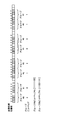
- the actual transmission SSB information includes one group bitmap and two intra-group bitmaps # 0 and # 1.
- the bit in the group bitmap indicates whether to apply the intragroup bitmap # 0 or the intragroup bitmap # 1 to the corresponding group.
- Bits in the group bitmap may indicate the intra-group bitmap # 0 by 0 and the intra-group bitmap # 1 by 1. In other words, the bits in the group bitmap may indicate the index of the intra-group bitmap.
- the actual transmission SSB information includes an 8-bit group bitmap, an 8-bit intra-group bitmap # 0, and an 8-bit intra-group bitmap # 1, the actual transmission SSB information has a size of 24 bits. is there.
- the arrangement of the actual transmission SSB shown in FIG. 8 is represented by a group bitmap of 00110011, an intragroup bitmap # 0 of 11111100, and an intragroup bitmap # 1 of 11001111.
- the actual transmission SSB information may include three or more intra-group bitmaps.
- the size of the group bitmap may be increased, and the group bitmap may indicate one of three or more intra-group bitmaps that are applied to each of the plurality of groups.
- the arrangement of actual transmission SSBs can be increased as compared with the existing notification method, and an arrangement suitable for the actual situation can be expressed.
- the group bitmap is a ternary value indicating whether an intra-group bitmap pattern is assigned to each group, whether all SSBs in the group are off, or whether all SSBs in the group are on. One may be shown.
- the group bitmap shows three values using 2 bits for each group. For example, as shown in FIG. 9, the bits corresponding to each group indicate by 00 that all SSBs in the group are off, and by 01 that all SSBs in the group are on, Assigning an intra-group bitmap pattern may be indicated by 10.
- the size of the actual transmission SSB information is 24 bits.
- the size of the actual transmission SSB information is 21 bits. Therefore, option 2 can suppress the size of the actual transmission SSB information compared to option 1.
- the arrangement of actual transmission SSBs can be increased compared to the existing notification method, and an arrangement suitable for the actual situation can be expressed.
- the flexibility of the number of actual transmission SSBs and the number of actual transmission SSBs is provided improves. Further, in a cell that supports SA and uses a frequency band of 6 GHz or more, RACH opportunities can be flexibly allocated without waste.
- non-standalone (NSA) may move to stand-alone in the future. If the setting of the beam pattern or the like is changed with the transition, it must be set again after the transition. It is preferable that the number of SSBs, the beam pattern, etc. do not change between NSA and SA. Therefore, it is preferable to notify the UE of the actual transmission SSB information not only to the cell supporting SA but also to the NSA cell in the same manner as the SA cell.
- wireless communication system Wireless communication system
- communication is performed using any one or a combination of the wireless communication methods according to the above embodiments of the present invention.
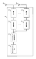
- FIG. 10 is a diagram illustrating an example of a schematic configuration of a wireless communication system according to an embodiment of the present invention.
- carrier aggregation (CA) and / or dual connectivity (DC) in which a plurality of basic frequency blocks (component carriers) each having a system bandwidth (for example, 20 MHz) of the LTE system as one unit are applied. can do.
- DC dual connectivity
- the wireless communication system 1 includes LTE (Long Term Evolution), LTE-A (LTE-Advanced), LTE-B (LTE-Beyond), SUPER 3G, IMT-Advanced 4G (4th generation mobile communication system), 5G. (5th generation mobile communication system), NR (New Radio), FRA (Future Radio Access), New-RAT (Radio Access Technology), etc., or a system that realizes these.
- the radio communication system 1 includes a radio base station 11 that forms a macro cell C1 having a relatively wide coverage, and a radio base station 12 (12a-12c) that is arranged in the macro cell C1 and forms a small cell C2 that is narrower than the macro cell C1. It is equipped with. Moreover, the user terminal 20 is arrange
- the user terminal 20 can be connected to both the radio base station 11 and the radio base station 12. It is assumed that the user terminal 20 uses the macro cell C1 and the small cell C2 simultaneously by CA or DC. Moreover, the user terminal 20 may apply CA or DC using a plurality of cells (CC) (for example, 5 or less CCs, 6 or more CCs).
- CC cells
- Communication between the user terminal 20 and the radio base station 11 can be performed using a carrier having a relatively low frequency band (for example, 2 GHz) and a narrow bandwidth (also referred to as an existing carrier or a legacy carrier).
- a carrier having a relatively high frequency band for example, 3.5 GHz, 5 GHz, etc.
- the same carrier may be used.
- the configuration of the frequency band used by each radio base station is not limited to this.
- a wired connection for example, an optical fiber compliant with CPRI (Common Public Radio Interface), an X2 interface, etc.
- a wireless connection It may be configured to.
- the radio base station 11 and each radio base station 12 are connected to the higher station apparatus 30 and connected to the core network 40 via the higher station apparatus 30.
- the upper station device 30 includes, for example, an access gateway device, a radio network controller (RNC), a mobility management entity (MME), and the like, but is not limited thereto.
- RNC radio network controller
- MME mobility management entity
- Each radio base station 12 may be connected to the higher station apparatus 30 via the radio base station 11.
- the radio base station 11 is a radio base station having a relatively wide coverage, and may be called a macro base station, an aggregation node, an eNB (eNodeB), a transmission / reception point, or the like.
- the radio base station 12 is a radio base station having local coverage, and includes a small base station, a micro base station, a pico base station, a femto base station, a HeNB (Home eNodeB), an RRH (Remote Radio Head), and transmission / reception. It may be called a point.
- the radio base stations 11 and 12 are not distinguished, they are collectively referred to as a radio base station 10.
- Each user terminal 20 is a terminal that supports various communication schemes such as LTE and LTE-A, and may include not only a mobile communication terminal (mobile station) but also a fixed communication terminal (fixed station).
- orthogonal frequency division multiple access (OFDMA) is applied to the downlink, and single carrier-frequency division multiple access (SC-FDMA) is used for the uplink.
- SC-FDMA single carrier-frequency division multiple access
- Frequency Division Multiple Access and / or OFDMA is applied.
- OFDMA is a multi-carrier transmission scheme that performs communication by dividing a frequency band into a plurality of narrow frequency bands (subcarriers) and mapping data to each subcarrier.
- SC-FDMA is a single-carrier transmission scheme that reduces interference between terminals by dividing the system bandwidth into bands each having one or more continuous resource blocks for each terminal, and by using a plurality of terminals with mutually different bands. is there.
- the uplink and downlink radio access schemes are not limited to these combinations, and other radio access schemes may be used.
- downlink channels include a downlink shared channel (PDSCH) shared by each user terminal 20, a broadcast channel (PBCH: Physical Broadcast Channel), a downlink L1 / L2 control channel, and the like. Used. User data, higher layer control information, SIB (System Information Block), etc. are transmitted by PDSCH. Also, MIB (Master Information Block) is transmitted by PBCH.
- PDSCH downlink shared channel
- PBCH Physical Broadcast Channel
- SIB System Information Block
- MIB Master Information Block
- Downlink L1 / L2 control channels include PDCCH (Physical Downlink Control Channel), EPDCCH (Enhanced Physical Downlink Control Channel), PCFICH (Physical Control Format Indicator Channel), PHICH (Physical Hybrid-ARQ Indicator Channel), and the like.
- Downlink control information (DCI: Downlink Control Information) including PDSCH and / or PUSCH scheduling information is transmitted by the PDCCH.
- scheduling information may be notified by DCI.
- DCI for scheduling DL data reception may be referred to as DL assignment
- DCI for scheduling UL data transmission may be referred to as UL grant.
- the number of OFDM symbols used for PDCCH is transmitted by PCFICH.
- the PHICH transmits HARQ (Hybrid Automatic Repeat reQuest) acknowledgment information (for example, retransmission control information, HARQ-ACK, ACK / NACK, etc.) to the PUSCH.
- HARQ Hybrid Automatic Repeat reQuest
- EPDCCH is frequency-division multiplexed with PDSCH (downlink shared data channel), and is used for transmission of DCI and the like, similar to PDCCH.
- an uplink shared channel (PUSCH) shared by each user terminal 20
- an uplink control channel (PUCCH: Physical Uplink Control Channel)
- a random access channel (PRACH: Physical Random Access Channel)
- User data, higher layer control information, etc. are transmitted by PUSCH.
- downlink radio quality information CQI: Channel Quality Indicator
- delivery confirmation information SR
- scheduling request etc.
- a random access preamble for establishing connection with a cell is transmitted by the PRACH.
- a cell-specific reference signal CRS
- CSI-RS channel state information reference signal
- DMRS demodulation reference signal
- PRS Positioning Reference Signal
- a measurement reference signal SRS: Sounding Reference Signal
- a demodulation reference signal DMRS
- the DMRS may be referred to as a user terminal specific reference signal (UE-specific Reference Signal). Further, the transmitted reference signal is not limited to these.
- FIG. 11 is a diagram illustrating an example of the overall configuration of a radio base station according to an embodiment of the present invention.
- the radio base station 10 includes a plurality of transmission / reception antennas 101, an amplifier unit 102, a transmission / reception unit 103, a baseband signal processing unit 104, a call processing unit 105, and a transmission path interface 106.
- the transmission / reception antenna 101, the amplifier unit 102, and the transmission / reception unit 103 may each be configured to include one or more.
- User data transmitted from the radio base station 10 to the user terminal 20 via the downlink is input from the higher station apparatus 30 to the baseband signal processing unit 104 via the transmission path interface 106.
- PDCP Packet Data Convergence Protocol
- RLC Radio Link Control
- MAC Medium Access
- Retransmission control for example, HARQ transmission processing
- scheduling transmission format selection, channel coding, Inverse Fast Fourier Transform (IFFT) processing, precoding processing, and other transmission processing
- IFFT Inverse Fast Fourier Transform
- precoding processing precoding processing, and other transmission processing
- the downlink control signal is also subjected to transmission processing such as channel coding and inverse fast Fourier transform, and is transferred to the transmission / reception unit 103.
- the transmission / reception unit 103 converts the baseband signal output by precoding for each antenna from the baseband signal processing unit 104 to a radio frequency band and transmits the converted signal.
- the radio frequency signal frequency-converted by the transmission / reception unit 103 is amplified by the amplifier unit 102 and transmitted from the transmission / reception antenna 101.
- the transmission / reception unit 103 can be configured by a transmitter / receiver, a transmission / reception circuit, or a transmission / reception device, which is described based on common recognition in the technical field according to the present invention.
- the transmission / reception part 103 may be comprised as an integral transmission / reception part, and may be comprised from a transmission part and a receiving part.
- the radio frequency signal received by the transmission / reception antenna 101 is amplified by the amplifier unit 102.
- the transmission / reception unit 103 receives the uplink signal amplified by the amplifier unit 102.
- the transmission / reception unit 103 converts the frequency of the received signal into a baseband signal and outputs it to the baseband signal processing unit 104.
- the baseband signal processing unit 104 performs fast Fourier transform (FFT) processing, inverse discrete Fourier transform (IDFT: Inverse Discrete Fourier Transform) processing, and error correction on user data included in the input upstream signal.
- FFT fast Fourier transform
- IDFT inverse discrete Fourier transform
- Decoding, MAC retransmission control reception processing, RLC layer and PDCP layer reception processing are performed and transferred to the upper station apparatus 30 via the transmission path interface 106.
- the call processor 105 performs communication channel call processing (setting, release, etc.), status management of the radio base station 10, radio resource management, and the like.
- the transmission path interface 106 transmits and receives signals to and from the higher station apparatus 30 via a predetermined interface.
- the transmission path interface 106 transmits / receives signals (backhaul signaling) to / from other radio base stations 10 via an interface between base stations (for example, an optical fiber compliant with CPRI (Common Public Radio Interface), X2 interface). May be.
- CPRI Common Public Radio Interface
- X2 interface May be.
- the transmission / reception unit 103 may transmit group information and pattern information. Moreover, the transmission / reception part 103 may transmit a synchronizing signal block (for example, SSB, SS / PBCH block) in the resource shown by group information and pattern information.
- a synchronizing signal block for example, SSB, SS / PBCH block
- FIG. 12 is a diagram illustrating an example of a functional configuration of a radio base station according to an embodiment of the present invention.
- the functional block of the characteristic part in this embodiment is mainly shown, and the wireless base station 10 shall also have another functional block required for radio
- the baseband signal processing unit 104 includes at least a control unit (scheduler) 301, a transmission signal generation unit 302, a mapping unit 303, a reception signal processing unit 304, and a measurement unit 305. These configurations may be included in the radio base station 10, and a part or all of the configurations may not be included in the baseband signal processing unit 104.
- the control unit (scheduler) 301 controls the entire radio base station 10.
- the control part 301 can be comprised from the controller, the control circuit, or control apparatus demonstrated based on the common recognition in the technical field which concerns on this invention.
- the control unit 301 controls, for example, signal generation by the transmission signal generation unit 302, signal allocation by the mapping unit 303, and the like.
- the control unit 301 also controls signal reception processing by the reception signal processing unit 304, signal measurement by the measurement unit 305, and the like.
- the control unit 301 schedules system information, downlink data signals (for example, signals transmitted by PDSCH), downlink control signals (for example, signals transmitted by PDCCH and / or EPDCCH, delivery confirmation information, etc.) (for example, resource Control).
- the control unit 301 controls generation of a downlink control signal, a downlink data signal, and the like based on a result of determining whether or not retransmission control is necessary for the uplink data signal.
- the control unit 301 controls scheduling of synchronization signals (for example, PSS (Primary Synchronization Signal) / SSS (Secondary Synchronization Signal)), downlink reference signals (for example, CRS, CSI-RS, DMRS) and the like.
- the control unit 301 includes an uplink data signal (for example, a signal transmitted by PUSCH), an uplink control signal (for example, a signal transmitted by PUCCH and / or PUSCH, delivery confirmation information, etc.), a random access preamble (for example, by PRACH). (Sending signal), scheduling of uplink reference signals and the like are controlled.
- an uplink data signal for example, a signal transmitted by PUSCH
- an uplink control signal for example, a signal transmitted by PUCCH and / or PUSCH, delivery confirmation information, etc.
- a random access preamble for example, by PRACH.
- the transmission signal generation unit 302 generates a downlink signal (downlink control signal, downlink data signal, downlink reference signal, etc.) based on an instruction from the control unit 301, and outputs it to the mapping unit 303.
- the transmission signal generation unit 302 can be configured by a signal generator, a signal generation circuit, or a signal generation device described based on common recognition in the technical field according to the present invention.
- the transmission signal generation unit 302 generates, for example, a DL assignment for notifying downlink data allocation information and / or a UL grant for notifying uplink data allocation information based on an instruction from the control unit 301.
- the DL assignment and UL grant are both DCI and follow the DCI format.
- the downlink data signal is subjected to coding processing and modulation processing according to a coding rate, a modulation scheme, and the like determined based on channel state information (CSI: Channel State Information) from each user terminal 20.
- CSI Channel State Information
- the mapping unit 303 maps the downlink signal generated by the transmission signal generation unit 302 to a predetermined radio resource based on an instruction from the control unit 301, and outputs it to the transmission / reception unit 103.
- the mapping unit 303 can be configured by a mapper, a mapping circuit, or a mapping device described based on common recognition in the technical field according to the present invention.
- the reception signal processing unit 304 performs reception processing (for example, demapping, demodulation, decoding, etc.) on the reception signal input from the transmission / reception unit 103.
- the received signal is, for example, an uplink signal (uplink control signal, uplink data signal, uplink reference signal, etc.) transmitted from the user terminal 20.
- the reception signal processing unit 304 can be configured by a signal processor, a signal processing circuit, or a signal processing device described based on common recognition in the technical field according to the present invention.
- the reception signal processing unit 304 outputs the information decoded by the reception processing to the control unit 301. For example, when receiving PUCCH including HARQ-ACK, HARQ-ACK is output to control section 301.
- the reception signal processing unit 304 outputs the reception signal and / or the signal after reception processing to the measurement unit 305.
- the measurement unit 305 performs measurement on the received signal.
- the measurement part 305 can be comprised from the measuring device, measurement circuit, or measurement apparatus demonstrated based on common recognition in the technical field which concerns on this invention.
- the measurement unit 305 may perform RRM (Radio Resource Management) measurement, CSI (Channel State Information) measurement, and the like based on the received signal.
- the measurement unit 305 receives received power (for example, RSRP (Reference Signal Received Power)), received quality (for example, RSRQ (Reference Signal Received Quality), SINR (Signal to Interference plus Noise Ratio)), signal strength (for example, RSSI ( Received Signal Strength Indicator)), propagation path information (for example, CSI), etc. may be measured.
- the measurement result may be output to the control unit 301.
- FIG. 13 is a diagram illustrating an example of the overall configuration of a user terminal according to an embodiment of the present invention.
- the user terminal 20 includes a plurality of transmission / reception antennas 201, an amplifier unit 202, a transmission / reception unit 203, a baseband signal processing unit 204, and an application unit 205.
- the transmission / reception antenna 201, the amplifier unit 202, and the transmission / reception unit 203 may each be configured to include one or more.
- the radio frequency signal received by the transmission / reception antenna 201 is amplified by the amplifier unit 202.
- the transmission / reception unit 203 receives the downlink signal amplified by the amplifier unit 202.
- the transmission / reception unit 203 converts the frequency of the received signal into a baseband signal and outputs it to the baseband signal processing unit 204.
- the transmission / reception unit 203 can be configured by a transmitter / receiver, a transmission / reception circuit, or a transmission / reception device described based on common recognition in the technical field according to the present invention.
- the transmission / reception unit 203 may be configured as an integral transmission / reception unit, or may be configured from a transmission unit and a reception unit.
- the baseband signal processing unit 204 performs FFT processing, error correction decoding, retransmission control reception processing, and the like on the input baseband signal.
- the downlink user data is transferred to the application unit 205.
- the application unit 205 performs processing related to layers higher than the physical layer and the MAC layer. Also, broadcast information of downlink data may be transferred to the application unit 205.
- uplink user data is input from the application unit 205 to the baseband signal processing unit 204.
- the baseband signal processing unit 204 performs transmission / reception units for retransmission control (for example, HARQ transmission processing), channel coding, precoding, discrete Fourier transform (DFT) processing, IFFT processing, and the like.
- the transmission / reception unit 203 converts the baseband signal output from the baseband signal processing unit 204 into a radio frequency band and transmits it.
- the radio frequency signal frequency-converted by the transmission / reception unit 203 is amplified by the amplifier unit 202 and transmitted from the transmission / reception antenna 201.
- the transmission / reception unit 203 indicates whether or not the synchronization signal block is transmitted at each of a plurality of transmission candidate positions in the group of transmission candidate positions of the synchronization signal block (for example, SS block, SS / PBCH block).
- Information for example, intra-group bitmap, InOneGroup, bitmap in group, intra-group bitmap # 0
- group information for example, group bitmap, groupPresence
- the transmission / reception unit 203 may receive instruction information (for example, defaultSSBpresenceInGroup) regarding interpretation of group information.
- instruction information for example, defaultSSBpresenceInGroup
- the transmission / reception unit 203 may further receive additional pattern information (for example, intra-group bitmap # 1) indicating whether or not a synchronization signal block is transmitted at each of a plurality of transmission candidate positions.
- additional pattern information for example, intra-group bitmap # 1 indicating whether or not a synchronization signal block is transmitted at each of a plurality of transmission candidate positions.
- the transmission / reception unit 203 sets configuration information (for example, RRC signaling indicating TDD DL / UL configuration, RMSI, etc.) for setting one of downlink, uplink, and flexible for a specific period (for example, slot). DCI etc.) may be received.
- configuration information for example, RRC signaling indicating TDD DL / UL configuration, RMSI, etc.
- FIG. 14 is a diagram illustrating an example of a functional configuration of a user terminal according to an embodiment of the present invention.
- the functional blocks of the characteristic part in the present embodiment are mainly shown, and the user terminal 20 also has other functional blocks necessary for wireless communication.
- the baseband signal processing unit 204 included in the user terminal 20 includes at least a control unit 401, a transmission signal generation unit 402, a mapping unit 403, a reception signal processing unit 404, and a measurement unit 405. Note that these configurations may be included in the user terminal 20, and some or all of the configurations may not be included in the baseband signal processing unit 204.
- the control unit 401 controls the entire user terminal 20.
- the control unit 401 can be composed of a controller, a control circuit, or a control device described based on common recognition in the technical field according to the present invention.
- the control unit 401 controls, for example, signal generation by the transmission signal generation unit 402, signal allocation by the mapping unit 403, and the like.
- the control unit 401 also controls signal reception processing by the reception signal processing unit 404, signal measurement by the measurement unit 405, and the like.
- the control unit 401 acquires the downlink control signal and the downlink data signal transmitted from the radio base station 10 from the reception signal processing unit 404.
- the control unit 401 controls the generation of the uplink control signal and / or the uplink data signal based on the result of determining the necessity of retransmission control for the downlink control signal and / or the downlink data signal.
- control unit 401 When the control unit 401 acquires various types of information notified from the radio base station 10 from the reception signal processing unit 404, the control unit 401 may update parameters used for control based on the information.
- the transmission signal generation unit 402 generates an uplink signal (uplink control signal, uplink data signal, uplink reference signal, etc.) based on an instruction from the control unit 401 and outputs the uplink signal to the mapping unit 403.
- the transmission signal generation unit 402 can be configured by a signal generator, a signal generation circuit, or a signal generation device described based on common recognition in the technical field according to the present invention.
- the transmission signal generation unit 402 generates an uplink control signal related to delivery confirmation information, channel state information (CSI), and the like based on an instruction from the control unit 401, for example. In addition, the transmission signal generation unit 402 generates an uplink data signal based on an instruction from the control unit 401. For example, the transmission signal generation unit 402 is instructed by the control unit 401 to generate an uplink data signal when the UL grant is included in the downlink control signal notified from the radio base station 10.
- CSI channel state information
- the mapping unit 403 maps the uplink signal generated by the transmission signal generation unit 402 to a radio resource based on an instruction from the control unit 401, and outputs the radio signal to the transmission / reception unit 203.
- the mapping unit 403 can be configured by a mapper, a mapping circuit, or a mapping device described based on common recognition in the technical field according to the present invention.
- the reception signal processing unit 404 performs reception processing (for example, demapping, demodulation, decoding, etc.) on the reception signal input from the transmission / reception unit 203.
- the received signal is, for example, a downlink signal (downlink control signal, downlink data signal, downlink reference signal, etc.) transmitted from the radio base station 10.
- the reception signal processing unit 404 can be configured by a signal processor, a signal processing circuit, or a signal processing device described based on common recognition in the technical field according to the present invention. Further, the reception signal processing unit 404 can constitute a reception unit according to the present invention.
- the reception signal processing unit 404 outputs the information decoded by the reception processing to the control unit 401.
- the reception signal processing unit 404 outputs, for example, broadcast information, system information, RRC signaling, DCI, and the like to the control unit 401.
- the reception signal processing unit 404 outputs the reception signal and / or the signal after reception processing to the measurement unit 405.
- the measurement unit 405 performs measurement on the received signal.
- the measurement part 405 can be comprised from the measuring device, measurement circuit, or measurement apparatus demonstrated based on common recognition in the technical field which concerns on this invention.
- the measurement unit 405 may perform RRM measurement, CSI measurement, and the like based on the received signal.
- the measurement unit 405 may measure received power (for example, RSRP), reception quality (for example, RSRQ, SINR), signal strength (for example, RSSI), propagation path information (for example, CSI), and the like.
- the measurement result may be output to the control unit 401.
- control unit 401 assumes that the synchronization signal block is transmitted at all the transmission candidate positions in the specific group (for example, the group corresponding to the specific value in the group bitmap), and a plurality of the specific group One of the transmission candidate positions may be controlled based on the group information.
- control unit 401 may assume that the synchronization signal block is transmitted at all the transmission candidate positions in the specific group (first A fifth aspect).
- the control unit 401 assumes that the synchronization signal block is transmitted at all transmission candidate positions in the specific group based on the instruction information. Alternatively, it may be determined whether it is assumed that the synchronization signal block is not transmitted at all the transmission candidate positions in the specific group (second mode).
- control unit 401 adds pattern information (for example, intra-group bitmap # 0) and additional pattern information (for example, intra-group bitmap # 1) to elements (for example, bits) corresponding to a specific group in the group information.
- pattern information for example, intra-group bitmap # 0
- additional pattern information for example, intra-group bitmap # 1
- elements for example, bits
- a plurality of transmission candidate positions in the specific group may be determined (fourth mode).
- control unit 401 may assume that a synchronization signal block is not transmitted within a specific period (for example, a slot) regardless of group information and pattern information (third Embodiment).
- the control unit 401 assumes that the synchronization signal block is transmitted at all transmission candidate positions in the specific group, and within the specific group.
- each functional block is realized using one device physically and / or logically coupled, or directly and / or two or more devices physically and / or logically separated. Alternatively, it may be realized indirectly by connecting (for example, using wired and / or wireless) and using these plural devices.
- a radio base station, a user terminal, etc. in an embodiment of the present invention may function as a computer that performs processing of the radio communication method of the present invention.
- FIG. 15 is a diagram illustrating an example of a hardware configuration of a radio base station and a user terminal according to an embodiment of the present invention.
- the wireless base station 10 and the user terminal 20 described above may be physically configured as a computer device including a processor 1001, a memory 1002, a storage 1003, a communication device 1004, an input device 1005, an output device 1006, a bus 1007, and the like. Good.
- the term “apparatus” can be read as a circuit, a device, a unit, or the like.
- the hardware configurations of the radio base station 10 and the user terminal 20 may be configured to include one or a plurality of each device illustrated in the figure, or may be configured not to include some devices.
- processor 1001 may be implemented by one or more chips.
- Each function in the radio base station 10 and the user terminal 20 is calculated by causing the processor 1001 to perform calculations by reading predetermined software (programs) on hardware such as the processor 1001 and the memory 1002, for example, via the communication device 1004. This is realized by controlling communication and controlling reading and / or writing of data in the memory 1002 and the storage 1003.
- the processor 1001 controls the entire computer by operating an operating system, for example.
- the processor 1001 may be configured by a central processing unit (CPU) including an interface with peripheral devices, a control device, an arithmetic device, a register, and the like.
- CPU central processing unit
- the baseband signal processing unit 104 (204) and the call processing unit 105 described above may be realized by the processor 1001.
- the processor 1001 reads programs (program codes), software modules, data, and the like from the storage 1003 and / or the communication device 1004 to the memory 1002, and executes various processes according to these.
- programs program codes
- software modules software modules
- data data
- the control unit 401 of the user terminal 20 may be realized by a control program stored in the memory 1002 and operating in the processor 1001, and may be realized similarly for other functional blocks.
- the memory 1002 is a computer-readable recording medium such as a ROM (Read Only Memory), an EPROM (Erasable Programmable ROM), an EEPROM (Electrically EPROM), a RAM (Random Access Memory), or any other suitable storage medium. It may be configured by one.
- the memory 1002 may be called a register, a cache, a main memory (main storage device), or the like.
- the memory 1002 can store programs (program codes), software modules, and the like that can be executed to implement the wireless communication method according to an embodiment of the present invention.
- the storage 1003 is a computer-readable recording medium such as a flexible disk, a floppy (registered trademark) disk, a magneto-optical disk (for example, a compact disk (CD-ROM (Compact Disc ROM)), a digital versatile disk, Blu-ray® disk), removable disk, hard disk drive, smart card, flash memory device (eg, card, stick, key drive), magnetic stripe, database, server, or other suitable storage medium It may be constituted by.
- the storage 1003 may be referred to as an auxiliary storage device.
- the communication device 1004 is hardware (transmission / reception device) for performing communication between computers via a wired and / or wireless network, and is also referred to as a network device, a network controller, a network card, a communication module, or the like.
- the communication device 1004 includes, for example, a high-frequency switch, a duplexer, a filter, a frequency synthesizer, etc., in order to realize frequency division duplex (FDD) and / or time division duplex (TDD). It may be configured.
- FDD frequency division duplex
- TDD time division duplex
- the transmission / reception antenna 101 (201), the amplifier unit 102 (202), the transmission / reception unit 103 (203), the transmission path interface 106, and the like described above may be realized by the communication device 1004.
- the input device 1005 is an input device (for example, a keyboard, a mouse, a microphone, a switch, a button, a sensor, etc.) that accepts an input from the outside.
- the output device 1006 is an output device (for example, a display, a speaker, an LED (Light Emitting Diode) lamp, etc.) that performs output to the outside.
- the input device 1005 and the output device 1006 may have an integrated configuration (for example, a touch panel).
- the devices such as the processor 1001 and the memory 1002 are connected by a bus 1007 for communicating information.
- the bus 1007 may be configured using a single bus, or may be configured using a different bus for each device.
- the radio base station 10 and the user terminal 20 include a microprocessor, a digital signal processor (DSP), an ASIC (Application Specific Integrated Circuit), a PLD (Programmable Logic Device), an FPGA (Field Programmable Gate Array), and the like. It may be configured including hardware, and a part or all of each functional block may be realized using the hardware. For example, the processor 1001 may be implemented using at least one of these hardware.
- DSP digital signal processor
- ASIC Application Specific Integrated Circuit
- PLD Programmable Logic Device
- FPGA Field Programmable Gate Array
- the channel and / or symbol may be a signal (signaling).
- the signal may be a message.
- the reference signal may be abbreviated as RS (Reference Signal), and may be referred to as a pilot, a pilot signal, or the like depending on an applied standard.
- a component carrier CC: Component Carrier
- CC Component Carrier
- the radio frame may be configured by one or a plurality of periods (frames) in the time domain.
- Each of the one or more periods (frames) constituting the radio frame may be referred to as a subframe.
- a subframe may be composed of one or more slots in the time domain.
- the subframe may have a fixed time length (eg, 1 ms) that does not depend on the neurology.
- the slot may be configured by one or a plurality of symbols (OFDM (Orthogonal Frequency Division Multiplexing) symbol, SC-FDMA (Single Carrier Frequency Division Multiple Access) symbol, etc.) in the time domain.
- the slot may be a time unit based on the numerology.
- the slot may include a plurality of mini slots. Each minislot may be configured with one or more symbols in the time domain. The minislot may also be called a subslot.
- Radio frame, subframe, slot, minislot, and symbol all represent time units when transmitting signals. Different names may be used for the radio frame, subframe, slot, minislot, and symbol.
- one subframe may be called a transmission time interval (TTI)
- TTI transmission time interval
- a plurality of consecutive subframes may be called a TTI
- TTI slot or one minislot
- a unit representing TTI may be called a slot, a minislot, or the like instead of a subframe.
- TTI means, for example, a minimum time unit for scheduling in wireless communication.
- a radio base station performs scheduling for assigning radio resources (frequency bandwidth, transmission power, etc. that can be used in each user terminal) to each user terminal in units of TTI.
- the definition of TTI is not limited to this.
- the TTI may be a transmission time unit of a channel-encoded data packet (transport block), a code block, and / or a code word, or may be a processing unit such as scheduling or link adaptation.
- a time interval for example, the number of symbols
- a transport block, a code block, and / or a code word is actually mapped may be shorter than the TTI.
- one or more TTIs may be the minimum scheduling unit. Further, the number of slots (the number of mini-slots) constituting the minimum time unit of the scheduling may be controlled.
- a TTI having a time length of 1 ms may be called a normal TTI (TTI in LTE Rel. 8-12), a normal TTI, a long TTI, a normal subframe, a normal subframe, or a long subframe.
- a TTI shorter than a normal TTI may be called a shortened TTI, a short TTI, a partial TTI (partial or fractional TTI), a shortened subframe, a short subframe, a minislot, or a subslot.
- a long TTI (eg, normal TTI, subframe, etc.) may be read as a TTI having a time length exceeding 1 ms, and a short TTI (eg, shortened TTI) is less than the TTI length of the long TTI and 1 ms. It may be replaced with a TTI having the above TTI length.
- a resource block is a resource allocation unit in the time domain and the frequency domain, and may include one or a plurality of continuous subcarriers (subcarriers) in the frequency domain. Further, the RB may include one or a plurality of symbols in the time domain, and may have a length of 1 slot, 1 mini slot, 1 subframe, or 1 TTI. One TTI and one subframe may each be composed of one or a plurality of resource blocks.
- One or more RBs include physical resource blocks (PRB), sub-carrier groups (SCG), resource element groups (REG), PRB pairs, RB pairs, etc. May be called.
- the resource block may be configured by one or a plurality of resource elements (RE: Resource Element).
- RE Resource Element
- 1RE may be a radio resource region of 1 subcarrier and 1 symbol.
- the structure of the above-described radio frame, subframe, slot, minislot, symbol, etc. is merely an example.
- the number of subframes included in a radio frame, the number of slots per subframe or radio frame, the number of minislots included in the slot, the number of symbols and RBs included in the slot or minislot, and the RB The number of subcarriers, the number of symbols in the TTI, the symbol length, the cyclic prefix (CP) length, and the like can be variously changed.
- the information, parameters, and the like described in this specification may be expressed using absolute values, may be expressed using relative values from a predetermined value, or other corresponding information may be used. May be represented.
- the radio resource may be indicated by a predetermined index.
- names used for parameters and the like are not limited names in any way.
- various channels PUCCH (Physical Uplink Control Channel), PDCCH (Physical Downlink Control Channel), etc.
- information elements can be identified by any suitable name, so the various channels and information elements assigned to them.
- the name is not limited in any way.
- information, signals, etc. can be output from the upper layer to the lower layer and / or from the lower layer to the upper layer.
- Information, signals, and the like may be input / output via a plurality of network nodes.
- the input / output information, signals, etc. may be stored in a specific location (for example, a memory) or may be managed using a management table. Input / output information, signals, and the like can be overwritten, updated, or added. The output information, signals, etc. may be deleted. Input information, signals, and the like may be transmitted to other devices.
- information notification includes physical layer signaling (eg, downlink control information (DCI), uplink control information (UCI)), upper layer signaling (eg, RRC (Radio Resource Control) signaling), It may be implemented by broadcast information (Master Information Block (MIB), System Information Block (SIB), etc.), MAC (Medium Access Control) signaling), other signals, or a combination thereof.
- DCI downlink control information
- UCI uplink control information
- RRC Radio Resource Control
- MIB Master Information Block
- SIB System Information Block
- MAC Medium Access Control
- the physical layer signaling may be referred to as L1 / L2 (Layer 1 / Layer 2) control information (L1 / L2 control signal), L1 control information (L1 control signal), or the like.
- the RRC signaling may be referred to as an RRC message, and may be, for example, an RRC connection setup (RRCConnectionSetup) message, an RRC connection reconfiguration (RRCConnectionReconfiguration) message, or the like.
- the MAC signaling may be notified using, for example, a MAC control element (MAC CE (Control Element)).
- notification of predetermined information is not limited to explicit notification, but implicitly (for example, by not performing notification of the predetermined information or other information) May be performed).
- the determination may be performed by a value represented by 1 bit (0 or 1), or may be performed by a boolean value represented by true or false.
- the comparison may be performed by numerical comparison (for example, comparison with a predetermined value).
- software, instructions, information, etc. may be transmitted / received via a transmission medium.
- software can use websites, servers using wired technology (coaxial cable, fiber optic cable, twisted pair, digital subscriber line (DSL), etc.) and / or wireless technology (infrared, microwave, etc.) , Or other remote sources, these wired and / or wireless technologies are included within the definition of transmission media.
- system and “network” used in this specification are used interchangeably.
- base station BS
- radio base station eNB
- gNB gNodeB
- cell gNodeB
- cell group a base station
- carrier a base station
- a base station may also be called in terms such as a fixed station, NodeB, eNodeB (eNB), access point, transmission point, reception point, femtocell, and small cell.
- the base station can accommodate one or a plurality of (for example, three) cells (also called sectors). If the base station accommodates multiple cells, the entire coverage area of the base station can be partitioned into multiple smaller areas, each smaller area being a base station subsystem (eg, an indoor small base station (RRH: Remote Radio Head)) can also provide communication services.
- a base station subsystem eg, an indoor small base station (RRH: Remote Radio Head)
- RRH Remote Radio Head
- the term “cell” or “sector” refers to part or all of the coverage area of a base station and / or base station subsystem that provides communication services in this coverage.
- MS mobile station
- UE user equipment
- terminal may be used interchangeably.
- a base station may also be called in terms such as a fixed station, NodeB, eNodeB (eNB), access point, transmission point, reception point, femtocell, and small cell.
- NodeB NodeB
- eNodeB eNodeB
- access point transmission point
- reception point femtocell
- small cell small cell
- a mobile station is defined by those skilled in the art as a subscriber station, mobile unit, subscriber unit, wireless unit, remote unit, mobile device, wireless device, wireless communication device, remote device, mobile subscriber station, access terminal, mobile terminal, wireless It may also be called terminal, remote terminal, handset, user agent, mobile client, client or some other suitable terminology.
- the radio base station in this specification may be read by the user terminal.
- each aspect / embodiment of the present invention may be applied to a configuration in which communication between a radio base station and a user terminal is replaced with communication between a plurality of user terminals (D2D: Device-to-Device).
- the user terminal 20 may have a function that the wireless base station 10 has.
- words such as “up” and “down” may be read as “side”.
- the uplink channel may be read as a side channel.
- a user terminal in this specification may be read by a radio base station.
- the wireless base station 10 may have a function that the user terminal 20 has.
- the operation performed by the base station may be performed by the upper node in some cases.
- various operations performed for communication with a terminal may include a base station and one or more network nodes other than the base station (for example, It is obvious that this can be done by MME (Mobility Management Entity), S-GW (Serving-Gateway), etc., but not limited thereto) or a combination thereof.
- MME Mobility Management Entity
- S-GW Serving-Gateway
- each aspect / embodiment described in this specification may be used alone, may be used in combination, or may be switched according to execution.
- the order of the processing procedures, sequences, flowcharts, and the like of each aspect / embodiment described in this specification may be changed as long as there is no contradiction.
- the methods described herein present the elements of the various steps in an exemplary order and are not limited to the specific order presented.
- Each aspect / embodiment described in this specification includes LTE (Long Term Evolution), LTE-A (LTE-Advanced), LTE-B (LTE-Beyond), SUPER 3G, IMT-Advanced, 4G (4th generation mobile) communication system), 5G (5th generation mobile communication system), FRA (Future Radio Access), New-RAT (Radio Access Technology), NR (New Radio), NX (New radio access), FX (Future generation radio access), GSM (registered trademark) (Global System for Mobile communications), CDMA2000, UMB (Ultra Mobile Broadband), IEEE 802.11 (Wi-Fi (registered trademark)), IEEE 802.16 (WiMAX (registered trademark)), IEEE 802 .20, UWB (Ultra-WideBand), Bluetooth (registered trademark) ), A system using another appropriate wireless communication method, and / or a next generation system extended based on these methods.
- LTE Long Term Evolution
- LTE-A Long Term Evolution-Advanced
- the phrase “based on” does not mean “based only on”, unless expressly specified otherwise. In other words, the phrase “based on” means both “based only on” and “based at least on.”
- any reference to elements using designations such as “first”, “second”, etc. as used herein does not generally limit the amount or order of those elements. These designations can be used herein as a convenient way to distinguish between two or more elements. Thus, reference to the first and second elements does not mean that only two elements can be employed or that the first element must precede the second element in some way.
- determining may encompass a wide variety of actions. For example, “determination” means calculating, computing, processing, deriving, investigating, looking up (eg, table, database or other data). It may be considered to “judge” (search in structure), ascertaining, etc.
- “determination (decision)” includes receiving (for example, receiving information), transmitting (for example, transmitting information), input (input), output (output), access ( accessing) (e.g., accessing data in memory), etc. may be considered to be “determining”. Also, “determination” is considered to be “determination (resolving)”, “selecting”, “choosing”, “establishing”, “comparing”, etc. Also good. That is, “determination (determination)” may be regarded as “determination (determination)” of some operation.
- connection is any direct or indirect connection between two or more elements or By coupling, it can include the presence of one or more intermediate elements between two elements that are “connected” or “coupled” to each other.
- the coupling or connection between the elements may be physical, logical, or a combination thereof. For example, “connection” may be read as “access”.
- the radio frequency domain can be considered “connected” or “coupled” to each other, such as with electromagnetic energy having wavelengths in the microwave and / or light (both visible and invisible) regions.
Abstract
In order to appropriately notify a resource having a synchronization signal block sent thereto, in future wireless communications systems, this user terminal has: a reception unit that receives pattern information and group information, said pattern information indicating whether or not a synchronization signal block is sent, for each of a plurality of candidate transmission positions in a group of candidate transmission positions for synchronization signal blocks and said group information indicating the method of application of the pattern information for each of a plurality of groups; and a control unit that controls either the assumption that a synchronization signal block is sent to all candidate transmission positions in a specific group or the determination of the plurality of candidate transmission positions within the specific group in accordance with the pattern information, controlling same on the basis of the group information.
Description
本発明は、次世代移動通信システムにおけるユーザ端末及び無線通信方法に関する。
The present invention relates to a user terminal and a wireless communication method in a next generation mobile communication system.
UMTS(Universal Mobile Telecommunications System)ネットワークにおいて、更なる高速データレート、低遅延などを目的としてロングタームエボリューション(LTE:Long Term Evolution)が仕様化された(非特許文献1)。また、LTE(LTE Rel.8、9)の更なる大容量、高度化などを目的として、LTE-A(LTEアドバンスト、LTE Rel.10、11、12、13)が仕様化された。
In the UMTS (Universal Mobile Telecommunications System) network, Long Term Evolution (LTE) has been specified for the purpose of further high data rate, low delay, etc. (Non-patent Document 1). In addition, LTE-A (LTE Advanced, LTE Rel. 10, 11, 12, 13) was specified for the purpose of further increasing the capacity and sophistication of LTE (LTE Rel. 8, 9).
LTEの後継システム(例えば、FRA(Future Radio Access)、5G(5th generation mobile communication system)、5G+(plus)、NR(New Radio)、NX(New radio access)、FX(Future generation radio access)、LTE Rel.14又は15以降などともいう)も検討されている。
LTE successor systems (for example, FRA (Future Radio Access), 5G (5th generation mobile communication system), 5G + (plus), NR (New Radio), NX (New radio access), FX (Future generation radio access), LTE Also referred to as Rel.
既存のLTEシステム(例えば、LTE Rel.8-13)において、ユーザ端末(UE:User Equipment)は、初期接続(initial access)手順(セルサーチ等とも呼ばれる)によって同期信号(PSS(Primary Synchronization Signal)及び/又はSSS(Secondary Synchronization Signal))を検出し、ネットワーク(例えば、無線基地局(eNB(eNode B)))との同期をとるとともに、接続するセルを識別する(例えば、セルID(Identifier)によって識別する)。
In an existing LTE system (for example, LTE Rel. 8-13), a user terminal (UE: User Equipment) is synchronized with a synchronization signal (PSS (Primary Synchronization Signal) by an initial access procedure (also called a cell search or the like). And / or SSS (Secondary Synchronization Signal) is detected and synchronized with a network (for example, a radio base station (eNB (eNode B))) and connected cells are identified (for example, a cell ID (Identifier)). Identified by).
また、UEは、セルサーチ後に、ブロードキャストチャネル(PBCH:Physical Broadcast Channel)で送信されるマスタ情報ブロック(MIB:Master Information Block)、下りリンク(DL)共有チャネル(PDSCH:Physical Downlink Shared Channel)で送信されるシステム情報ブロック(SIB:System Information Block)などを受信して、ネットワークとの通信のための設定情報(ブロードキャスト情報、システム情報などと呼ばれてもよい)を取得する。
In addition, after the cell search, the UE transmits a master information block (MIB) transmitted on a broadcast channel (PBCH: Physical Broadcast Channel) and a downlink (DL) shared channel (PDSCH: Physical Downlink Shared Channel). System information block (SIB: System Information Block) and the like to be received, and setting information for communication with the network (may be referred to as broadcast information, system information, etc.) is acquired.
将来の無線通信システム(例えば、NR又は5G)においては、同期信号及びブロードキャストチャネルを含むリソースユニットを同期信号ブロックと定義し、当該SSブロックに基づいて初期接続を行うことが検討されている。同期信号は、PSS及び/又はSSS、又は、NR-PSS及び/又はNR-SSS等とも呼ぶ。ブロードキャストチャネルは、PBCH又はNR-PBCH等とも呼ぶ。同期信号ブロックは、SSブロック(Synchronization Signal block:SSB)、又はSS/PBCHブロック等とも呼ぶ。
In future wireless communication systems (for example, NR or 5G), it is considered that a resource unit including a synchronization signal and a broadcast channel is defined as a synchronization signal block and an initial connection is performed based on the SS block. The synchronization signal is also referred to as PSS and / or SSS, or NR-PSS and / or NR-SSS. The broadcast channel is also called PBCH or NR-PBCH. The synchronization signal block is also called an SS block (Synchronization Signal block: SSB) or an SS / PBCH block.
ユーザ端末は、SSブロックが送信されるリソースを認識する必要がある。しかしながら、SSブロックが送信されるリソースを通知する情報量が制限されることによって、ユーザ端末は、そのリソースを正しく認識できないおそれがある。
The user terminal needs to recognize the resource to which the SS block is transmitted. However, since the amount of information for notifying the resource to which the SS block is transmitted is limited, the user terminal may not be able to recognize the resource correctly.
本発明はかかる点に鑑みてなされたものであり、将来の無線通信システムにおいて、同期信号ブロックが送信されるリソースを適切に通知するユーザ端末及び無線通信方法を提供することを目的の1つとする。
SUMMARY An advantage of some aspects of the invention is that it provides a user terminal and a wireless communication method that appropriately notify a resource to which a synchronization signal block is transmitted in a future wireless communication system. .
本発明の一態様に係るユーザ端末は、同期信号ブロックの送信候補位置のグループ内の複数の送信候補位置のそれぞれにおいて同期信号ブロックが送信されるか否かを示すパターン情報と、複数のグループのそれぞれに対する前記パターン情報の適用方法を示すグループ情報とを受信する受信部と、特定グループ内の全ての送信候補位置において同期信号ブロックが送信されると想定することと、前記特定グループ内の前記複数の送信候補位置を前記パターン情報に従って決定することと、の1つを前記グループ情報に基づいて制御する制御部と、を有することを特徴とする。
A user terminal according to an aspect of the present invention includes pattern information indicating whether or not a synchronization signal block is transmitted at each of a plurality of transmission candidate positions in a group of transmission signal candidate positions of a synchronization signal block, A receiving unit that receives group information indicating a method of applying the pattern information to each of the receiving unit, and assuming that a synchronization signal block is transmitted at all transmission candidate positions in the specific group; And a control unit that controls one of the transmission candidate positions based on the group information.
本発明によれば、将来の無線通信システムにおいて、同期信号ブロックが送信されるリソースを適切に通知できる。
According to the present invention, it is possible to appropriately notify the resource to which the synchronization signal block is transmitted in the future wireless communication system.
将来の無線通信システム(例えば、LTE Rel.14以降、5G又はNRなど)では、同期信号(SS、PSS及び/又はSSS、又は、NR-PSS及び/又はNR-SSS等をともいう)及びブロードキャストチャネル(ブロードキャスト信号、PBCH、又は、NR-PBCH等ともいう)を含む信号ブロック(SS/PBCHブロック、SS/PBCHブロック等ともいう)を定義することが検討されている。一以上の信号ブロックの集合は、信号バースト(SS/PBCHバースト又はSSバースト)とも呼ばれる。当該信号バースト内の複数の信号ブロックは、異なる時間に異なるビームで送信される(ビームスィープ(beam sweep)等ともいう)。
In future wireless communication systems (for example, LTE Rel. 14 or later, 5G or NR, etc.), synchronization signals (also referred to as SS, PSS and / or SSS, or NR-PSS and / or NR-SSS, etc.) and broadcast It has been studied to define a signal block (also referred to as SS / PBCH block, SS / PBCH block or the like) including a channel (also referred to as a broadcast signal, PBCH, or NR-PBCH). A set of one or more signal blocks is also called a signal burst (SS / PBCH burst or SS burst). A plurality of signal blocks in the signal burst are transmitted with different beams at different times (also referred to as beam sweep).
SS/PBCHブロックは、一以上のシンボル(例えば、OFDMシンボル)で構成される。具体的には、SS/PBCHブロックは、連続する複数のシンボルで構成されてもよい。当該SS/PBCHブロック内では、PSS、SSS及びNR-PBCHがそれぞれ異なる一以上のシンボルに配置されてもよい。例えば、SS/PBCHブロックは、1シンボルのPSS、1シンボルのSSS、2又は3シンボルのPBCHを含む4又は5シンボルでSS/PBCHブロックを構成することも検討されている。
The SS / PBCH block is composed of one or more symbols (for example, OFDM symbols). Specifically, the SS / PBCH block may be composed of a plurality of consecutive symbols. In the SS / PBCH block, PSS, SSS, and NR-PBCH may be arranged in one or more different symbols. For example, it is considered that the SS / PBCH block is composed of 4 or 5 symbols including 1 symbol PSS, 1 symbol SSS, 2 or 3 symbols PBCH.
1つ又は複数のSS/PBCHブロックの集合は、SS/PBCHバーストと呼ばれてもよい。SS/PBCHバーストは、周波数及び/又は時間リソースが連続するSS/PBCHブロックで構成されてもよいし、周波数及び/又は時間リソースが非連続のSS/PBCHブロックで構成されてもよい。SS/PBCHバーストは、所定の周期(SS/PBCHバースト周期と呼ばれてもよい)で設定されてもよいし、又は、非周期で設定されてもよい。
A set of one or more SS / PBCH blocks may be referred to as an SS / PBCH burst. The SS / PBCH burst may be composed of SS / PBCH blocks in which frequency and / or time resources are continuous, or may be composed of SS / PBCH blocks in which frequency and / or time resources are discontinuous. The SS / PBCH burst may be set with a predetermined period (may be referred to as an SS / PBCH burst period), or may be set with a non-period.
また、1つ又は複数のSS/PBCHバーストは、SS/PBCHバーストセット(SS/PBCHバーストシリーズ)と呼ばれてもよい。SS/PBCHバーストセットは周期的に設定される。ユーザ端末は、SS/PBCHバーストセットが周期的に(SS/PBCHバーストセット周期(SS burst set periodicity)で)送信されると想定して受信処理を制御してもよい。
Also, one or more SS / PBCH bursts may be referred to as an SS / PBCH burst set (SS / PBCH burst series). The SS / PBCH burst set is set periodically. The user terminal may control the reception process on the assumption that the SS / PBCH burst set is transmitted periodically (with SS / PBCH burst set period (SS burst set periodicity)).
図1は、SSバーストセットの一例を示す図である。図1Aでは、ビームスイーピングの一例が示される。図1A及び図1Bに示すように、無線基地局(例えば、gNB)は、ビームの指向性を時間的に異ならせて(ビームスイーピング)、異なるビームを用いて異なるSSブロックを送信してもよい。なお、図1A及び図1Bでは、マルチビームを用いた例が示されるが、シングルビームを用いてSSブロックを送信することも可能である。
FIG. 1 is a diagram showing an example of an SS burst set. In FIG. 1A, an example of beam sweeping is shown. As shown in FIG. 1A and FIG. 1B, a radio base station (eg, gNB) may transmit different SS blocks using different beams with different beam directivities in time (beam sweeping). . 1A and 1B show an example using a multi-beam, but it is also possible to transmit an SS block using a single beam.
図1Bに示すように、SSバーストは1つ以上のSSブロックで構成され、SSバーストセットは1つ以上のSSバーストで構成される。例えば、図1Bでは、SSバーストが8SSブロック#0~#7で構成されるものとするが、これに限られない。SSブロック#0~#7は、それぞれ異なるビーム#0~#7(図1A)で送信されてもよい。
As shown in FIG. 1B, an SS burst is composed of one or more SS blocks, and an SS burst set is composed of one or more SS bursts. For example, in FIG. 1B, the SS burst is composed of 8SS blocks # 0 to # 7, but the present invention is not limited to this. SS blocks # 0 to # 7 may be transmitted by different beams # 0 to # 7 (FIG. 1A).
図1Bに示すように、SSブロック#0~#7を含むSSバーストセットは、所定期間(例えば、5ms以下、SSバーストセット期間等ともいう)を超えないように送信されてもよい。また、SSバーストセットは、所定周期(例えば、5、10、20、40、80又は160ms、SSバーストセット周期等ともいう)で繰り返されてもよい。
As shown in FIG. 1B, an SS burst set including SS blocks # 0 to # 7 may be transmitted so as not to exceed a predetermined period (for example, 5 ms or less, also referred to as an SS burst set period). Further, the SS burst set may be repeated at a predetermined cycle (for example, 5, 10, 20, 40, 80, or 160 ms, also referred to as an SS burst set cycle).
なお、図1Bでは、SSブロック#1及び#2、#3及び#4、#5及び#6の間にそれぞれ所定の時間間隔があるが、当該時間間隔はなくともよく、他のSSブロック間(例えば、SSブロック#2及び#3、#5及び#6の間など)に設けられてもよい。当該時間間隔には、例えば、DL制御チャネル(PDCCH、NR-PDCCH又は下りリンク制御情報(DCI:Downlink Control Information)等ともいう)が送信されてもよいし、及び/又は、UL制御チャネル(PUCCH:Physical Uplink Control Channel)がユーザ端末から送信されてもよい。例えば、各SSブロックが4シンボルで構成される場合、14シンボルのスロット内には、2シンボルのPDCCHと2つのSSブロック、2シンボル分のPUCCH及びガード時間が含まれてもよい。
In FIG. 1B, there is a predetermined time interval between SS blocks # 1 and # 2, # 3 and # 4, # 5 and # 6, but this time interval may not be present, and between other SS blocks. (For example, between SS blocks # 2 and # 3, # 5 and # 6, etc.) may be provided. In the time interval, for example, a DL control channel (PDCCH, NR-PDCCH, or downlink control information (DCI)) may be transmitted and / or a UL control channel (PUCCH). : Physical Uplink Control Channel) may be transmitted from the user terminal. For example, when each SS block is configured by 4 symbols, a slot of 14 symbols may include 2 symbols of PDCCH, 2 SS blocks, 2 symbols of PUCCH, and guard time.
また、SSブロックに含まれるPBCH及び/又は、PBCH用のDMRS(DeModulation Reference Signal)(PBCH DMRS)を利用してSSブロックのインデックス(SSブロックインデックス)が通知される。UEは、PBCH(又は、PBCH DMRS)に基づいて、受信したSSブロックのSSブロックインデックスを把握することができる。
Also, the SS block index (SS block index) is notified using PBCH and / or DMB (DeModulation Reference Signal) (PBCH DMRS) for PBCH included in the SS block. The UE can grasp the SS block index of the received SS block based on the PBCH (or PBCH DMRS).
初期アクセス時にUEによって読まれるMSI(Minimum System Information)のうちMIB(Master Information Block)は、PBCHによって運ばれる。その残りのMSIがRMSI(Remaining Minimum System Information)であり、LTEにおけるSIB(System Information Block)1、SIB2に相当する。また、MIBによって示されるPDCCHによって、RMSIがスケジュールされる。
MIB (Master Information Block) of MSI (Minimum System Information) read by UE at initial access is carried by PBCH. The remaining MSI is RMSI (Remaining Minimum System Information), which corresponds to SIB (System Information Block) 1 and SIB 2 in LTE. Also, the RMSI is scheduled by the PDCCH indicated by the MIB.
NRでは、SSブロック(SSB)が、同期、セル検出、フレーム及び/又はスロットのタイミング検出などに用いられてもよい。5msのSSB送信期間内の複数のSSBは、同一のセルIDを示す。各SSBは、固有のSSBインデックスを示す。SSBインデックスは、SSB送信期間内のSSBの時間位置(送信候補位置)を決定する。
In NR, an SS block (SSB) may be used for synchronization, cell detection, frame and / or slot timing detection, and the like. A plurality of SSBs within a 5 ms SSB transmission period indicate the same cell ID. Each SSB indicates a unique SSB index. The SSB index determines the time position (transmission candidate position) of the SSB within the SSB transmission period.
周波数バンドに応じて1つのSSB送信周期内に送信できるSSBの最大数Lが決められてもよい。例えば、0-3GHzの周波数バンドにおけるLは4であり、3-6GHzの周波数バンドにおけるLは8であり、6-52.6GHzの周波数バンドにおけるLは64であってもよい。SSB送信周期は、5、10、20、40、80、160msの1つに設定されてもよい。
The maximum number L of SSBs that can be transmitted within one SSB transmission period may be determined according to the frequency band. For example, L in the frequency band of 0-3 GHz may be 4, L in the frequency band of 3-6 GHz may be 8, and L in the frequency band of 6-52.6 GHz may be 64. The SSB transmission period may be set to one of 5, 10, 20, 40, 80, and 160 ms.
なお、6GHzよりも低い周波数バンドは、sub-6、FR(Frequency Range)1と呼ばれてもよい。6GHzよりも高い周波数バンドは、above-6、FR2、ミリ波(millimeter wave)などと呼ばれてもよいし、24GHzよりも高い周波数バンドを指してもよい。
The frequency band lower than 6 GHz may be referred to as sub-6, FR (Frequency Range) 1. A frequency band higher than 6 GHz may be referred to as above-6, FR2, millimeter wave, etc., or may refer to a frequency band higher than 24 GHz.
SSB送信周期内に1つのSSB送信期間が含まれる。SSB送信期間(例えば、5ms)内のSSBの送信候補位置(タイミング、時間リソース)は、仕様によって規定されてもよい。SSB送信期間は、無線フレームの前半又は後半の5msハーフフレームであってもよい。例えば、6GHz以上の周波数バンド、120kHzのサブキャリア間隔(subcarrier spacing:SCS、ニューメロロジー)に対する、64個のSSBの送信候補位置が規定されてもよい。
One SSB transmission period is included in the SSB transmission cycle. SSB transmission candidate positions (timing, time resources) within an SSB transmission period (for example, 5 ms) may be defined by specifications. The SSB transmission period may be a 5 ms half frame in the first half or the second half of the radio frame. For example, 64 SSB transmission candidate positions may be defined for a frequency band of 6 GHz or more and a subcarrier spacing (SCS) of 120 kHz.
SSBの送信候補位置は、時間方向のSSBインデックスによって表されてもよい。
The SSB transmission candidate position may be represented by an SSB index in the time direction.
無線基地局(ネットワーク、gNB)は、L個以下の任意の数のSSBをSSB送信周期毎に送信してもよい。無線基地局は、ビットマップを用いて、実際に送信されるSSB(actually transmitted SSB、実送信SSB)をUEへ通知してもよい。
The radio base station (network, gNB) may transmit an arbitrary number of L or less SSBs every SSB transmission cycle. The radio base station may notify the UE of actually transmitted SSB (actually transmitted SSB) using a bitmap.
UEは、同期、セル検出、フレーム及び/又はスロットのタイミング検出などにおいては、1つのSSBを検出できれば良い。一方、UEは、レートマッチング、測定などにおいては、実送信SSBを認識することによって、レートマッチング、測定などを精度よく行うことができる。
The UE only needs to be able to detect one SSB in synchronization, cell detection, frame and / or slot timing detection, and the like. On the other hand, in rate matching and measurement, the UE can accurately perform rate matching and measurement by recognizing the actual transmission SSB.
実送信SSBの通知方法として、次の3つの実送信SSB情報の少なくとも1つを用いることが考えられる。
It is conceivable to use at least one of the following three actual transmission SSB information as a method of notifying the actual transmission SSB.
・RMSI内のバースト内SSB位置情報(例えば、ssb-PositionsInBurst)
-In-burst SSB position information in RMSI (for example, ssb-PositionsInBurst)
バースト内SSB位置情報は、RMSIに含まれる。バースト内SSB位置情報は、2つの情報要素、グループ内ビットマップ(InOneGroup、bitmap in group)及びグループビットマップ(groupPresence)を含む。グループ内ビットマップはグループ内の各送信候補位置におけるSSBが送信されるか否かを示す。グループビットマップは、SSB送信期間内の各グループが適用されるか否かを示す。
In-burst SSB position information is included in the RMSI. The intra-burst SSB position information includes two information elements, an intra-group bitmap (InOneGroup, bitmap in group), and a group bitmap (groupPresence). The intra-group bitmap indicates whether or not an SSB at each transmission candidate position in the group is transmitted. The group bitmap indicates whether each group in the SSB transmission period is applied.
RMSIがバースト内SSB位置情報を含むことにより、初期アクセスのUEはバースト内SSB位置情報を読むことができる。
Since the RMSI includes the SSB location information in the burst, the UE having the initial access can read the SSB location information in the burst.
・サービングセル構成共通情報(例えば、ServingCellConfigCommon)内のバースト内SSB位置情報(例えば、ssb-PositionsInBurst)
In-burst SSB position information (for example, ssb-PositionsInBurst) in serving cell configuration common information (for example, ServingCellConfigCommon)
サービングセル構成共通情報は、RRCシグナリングによってコネクテッドのUE(connected UE)へ通知される情報要素である。バースト内SSB位置情報は、サービングセル構成共通情報に含まれ、サービングセル(キャリア)における実送信SSBを示す。
The serving cell configuration common information is an information element notified to a connected UE (connected UE) by RRC signaling. The intra-burst SSB position information is included in the serving cell configuration common information and indicates the actual transmission SSB in the serving cell (carrier).
UEは、このバースト内SSB位置情報に基づいて、割り当てられたデータにおいて実送信SSBの周りのレートマッチングを行うことができる。
The UE can perform rate matching around the actual transmission SSB in the allocated data based on the intra-burst SSB position information.
バースト内SSB位置情報は、実送信SSBの送信候補位置毎のビットを含んでもよい。例えば、64ビットまでのビットマップ(フルビットマップ)を用いて、64個の送信候補位置における実送信SSBの有無をサポートしてもよい。
The intra-burst SSB position information may include a bit for each transmission candidate position of the actual transmission SSB. For example, the presence / absence of actual transmission SSBs at 64 transmission candidate positions may be supported using a bit map (full bit map) of up to 64 bits.
・SMTC(SS/PBCH block based measurement timing configuration)情報(例えば、smtc1)内の測定用SSB情報(例えば、SSB-ToMeasure)
-Measurement SSB information (for example, SSB-ToMeasure) in SMTC (SS / PBCH block based measurement timing configuration) information (for example, smtc1)
SMTC情報は、RRCシグナリングによってコネクテッドのUE(connected UE)へ通知されるメジャメント指示(例えば、measurement object)に含まれる情報要素である。測定用SSB情報は、SMTC情報に含まれ、メジャメント対象としてどのSSBを想定するかをフルビットマップによって示す。測定用SSB情報は、サービングセルだけでなく同じ周波数を用いる周辺セルの実送信SSBを示す。測定用SSB情報により示される実送信SSBは、サービングセル及び周辺セルにおける実送信SSBのスーパーセットである。測定用SSB情報において、サービングセル及び周辺セルの少なくとも1つにおいて送信されるSSBのビットはONを示す。UEは、測定用SSB情報を用いることによって、サービングセル及び周辺セルを漏れなく測定できる。また、サービングセル及び周辺セルのいずれにおいても送信されていないSSBのビットをOFFと示すことによって、UEの測定負荷を抑えることができる。
SMTC information is an information element included in a measurement instruction (for example, measurement object) notified to a connected UE (connected UE) by RRC signaling. The SSB information for measurement is included in the SMTC information and indicates which SSB is assumed as a measurement target by a full bitmap. The measurement SSB information indicates the actual transmission SSB of not only the serving cell but also the neighboring cells using the same frequency. The actual transmission SSB indicated by the measurement SSB information is a superset of the actual transmission SSB in the serving cell and the neighboring cells. In the measurement SSB information, the bit of the SSB transmitted in at least one of the serving cell and the neighboring cell indicates ON. The UE can measure the serving cell and the neighboring cells without omission by using the SSB information for measurement. Further, the measurement load of the UE can be suppressed by indicating that the SSB bit that is not transmitted in any of the serving cell and the neighboring cell is OFF.
サービングセル構成共通情報内のバースト内SSB位置情報、及びSMTC情報内の測定用SSB情報は、RRCシグナリングによって通知されるため、RMSIと比べて、サイズ(オーバーヘッド)の制約が緩い。フルビットマップを用いることができる。
The in-burst SSB position information in the serving cell configuration common information and the measurement SSB information in the SMTC information are notified by RRC signaling, and therefore, the size (overhead) is less restricted than the RMSI. A full bitmap can be used.
一方、RMSI内のバースト内SSB位置情報は、RMSIによって通知されるため、サイズ(オーバーヘッド)の制約が厳しい。RMSI内のバースト内SSB位置情報は、6GHz以下の周波数バンドにおいてはフルビットマップ(L=4又は8)を用いることができるが、6GHz以上の周波数バンドにおいてはフルビットマップ(L=64)を用いることができず、グループ内ビットマップ及びグループビットマップを用いる。例えば、グループ内ビットマップが8ビット、グループビットマップが8ビットである。
On the other hand, the intra-burst SSB position information in the RMSI is notified by the RMSI, so the size (overhead) is severely restricted. The intra-burst SSB position information in the RMSI can use a full bitmap (L = 4 or 8) in a frequency band of 6 GHz or less, but a full bitmap (L = 64) in a frequency band of 6 GHz or more. In-group bitmap and group bitmap are used. For example, the intra-group bitmap is 8 bits and the group bitmap is 8 bits.
図2は、6GHz以上の周波数バンドにおいて、120kHzのSCS、20msのSSB送信周期は20msを用いる場合の、SSBの送信候補位置の一例を示す図である。
FIG. 2 is a diagram illustrating an example of SSB transmission candidate positions when a 120 kHz SCS and a 20 ms SSB transmission period of 20 ms are used in a frequency band of 6 GHz or higher.
周波数バンド及びSCSに対応して、SSB送信期間(5ms)内の64個の送信候補位置が仕様によって規定されてもよい。この例においては、1つの無線フレーム(1ms)内の10スロットのうち、最初の8スロットは送信候補位置を含み、最後の2スロットは送信候補位置を含まない。この2スロットはULなどに利用するために確保される。最初の8スロットの各スロットは2つの送信候補位置を含む。1つの送信候補位置の長さは4シンボルである。
Corresponding to the frequency band and SCS, 64 transmission candidate positions within the SSB transmission period (5 ms) may be defined by the specification. In this example, out of 10 slots in one radio frame (1 ms), the first 8 slots include transmission candidate positions, and the last 2 slots do not include transmission candidate positions. These two slots are reserved for use in the UL. Each slot of the first 8 slots includes two transmission candidate positions. The length of one transmission candidate position is 4 symbols.
図3に示すように、SSB送信期間内の64個の送信候補位置のうち、先頭から48個のSSBだけを送信する場合の、実送信SSBの通知方法について説明する。
As shown in FIG. 3, an actual transmission SSB notification method when only 48 SSBs from the top of the 64 transmission candidate positions in the SSB transmission period are transmitted will be described.
フルビットマップを用いる場合、全ての送信候補位置に対応する64ビットを有する。この例においては、先頭から48ビットが1であり、残りの16ビットが0である。
When using a full bit map, it has 64 bits corresponding to all transmission candidate positions. In this example, 48 bits from the top are 1 and the remaining 16 bits are 0.
グループビットマップ及びグループ内ビットマップの組み合わせを用いる場合、8個の連続する送信候補位置を1グループとし、8個のグループにおける実送信SSBを示す。
When using a combination of a group bitmap and an intra-group bitmap, eight consecutive transmission candidate positions are defined as one group, and actual transmission SSBs in eight groups are indicated.
グループビットマップは、8ビットに対応するグループ#0-#7のうち、ビットが1であるグループにグループ内ビットマップのパターンが適用され、ビットが0であるグループに実送信SSBが含まれないことを示す。言い換えれば、UEは、ビットが1であるグループにおいて、グループ内ビットマップに従って実送信SSBの有無を決定し、ビットが0であるグループにおいて、実送信SSBが無いと解釈する。この例のグループビットマップにおいて、グループ#0-#5のビットは1であり、グループ#6、#7のビットは0である。
In the group bitmap, among the groups # 0 to # 7 corresponding to 8 bits, the intra-group bitmap pattern is applied to the group having the bit 1, and the actual transmission SSB is not included in the group having the bit 0. It shows that. In other words, the UE determines the presence / absence of the actual transmission SSB in the group whose bit is 1 according to the intra-group bitmap, and interprets that there is no actual transmission SSB in the group whose bit is 0. In the group bit map of this example, the bits of groups # 0 to # 5 are 1, and the bits of groups # 6 and # 7 are 0.
グループ内ビットマップは、8ビットに対応する送信候補位置#0-#7のうち、ビットが1である送信候補位置においてSSBが送信され、ビットが0である送信候補位置においてSSBが送信されないことを示す。この例のグループ内ビットマップにおいては、全ての送信候補位置のビットは1である。
In the intra-group bitmap, among the transmission candidate positions # 0 to # 7 corresponding to 8 bits, the SSB is transmitted at the transmission candidate position where the bit is 1, and the SSB is not transmitted at the transmission candidate position where the bit is 0. Indicates. In the intra-group bitmap in this example, the bits at all the transmission candidate positions are 1.
また、NRにおいては、TDDキャリアにおけるTDD DL/UL構成が、セミスタティックに(RRCシグナリング又はRMSIによって)UEへ通知されてもよいし、ダイナミックに(DCIによって)UEへ通知されてもよい。TDD DL/UL構成は、セミスタティックに通知されダイナミックに変更されてもよい。
Also, in the NR, the TDD DL / UL configuration in the TDD carrier may be notified semi-statically (via RRC signaling or RMSI) to the UE or dynamically (via DCI). The TDD DL / UL configuration may be notified semi-statically and dynamically changed.
図4に示すように、TDD DL/UL構成が、セミスタティックに設定される場合、DL(DL部分)、フレキシブル、又はUL(UL部分)を示す1又は2個のパターンが、与えられた周期(期間)に対してセル固有に設定されてもよい。TDD DL/UL構成が、セミスタティックに設定される場合、スロット毎の、DL、フレキシブル、又はULを示す任意のパターンが、与えられた周期(期間)に対してUE固有に設定されてもよい。
As shown in FIG. 4, when the TDD DL / UL configuration is set semi-statically, one or two patterns indicating DL (DL part), flexible, or UL (UL part) are given cycles. (Period) may be set specific to a cell. When the TDD DL / UL configuration is set semi-statically, any pattern indicating DL, flexible, or UL for each slot may be set UE-specific for a given period (period). .
周期は、0.5、0.625、1、1.25、2、2.5、5、10msの1つであってもよい。
The period may be one of 0.5, 0.625, 1, 1.25, 2, 2.5, 5, 10 ms.
また、初期アクセスのためのRACH(Random Access Channel又はPhysical Random Access Channel:PRACH)構成テーブルが検討されている。図5Aに示すように、RACH構成テーブルは、複数のエントリを有する。各エントリはRACH構成(RACH機会(RACH occasion))を示す。
Also, a RACH (Random Access Channel or Physical Random Access Channel: PRACH) configuration table for initial access is being studied. As shown in FIG. 5A, the RACH configuration table has a plurality of entries. Each entry indicates a RACH configuration (RACH opportunity).
1つのエントリは、RACH構成インデックス、プリアンブル(PRACH)フォーマット、RACH機会のSFNの条件(x及びy)、RACH機会のサブフレーム番号、RACH機会の開始シンボル、サブフレーム内のRACHスロット数、RACHスロット内のRACH機会数、を含んでもよい。
One entry includes a RACH configuration index, a preamble (PRACH) format, a RACH opportunity SFN condition (x and y), a RACH opportunity subframe number, a RACH opportunity start symbol, the number of RACH slots in the subframe, and a RACH slot. May include the number of RACH opportunities.
x及びyは、RACH機会がSFN番号 mod x=yとなるSFNに存在することを示す。サブフレーム内のRACHスロット数は、SCSが15kHzであれば1、SCSが30kHzであれば1または2である。
X and y indicate that the RACH opportunity exists in the SFN with the SFN number mod x = y. The number of RACH slots in the subframe is 1 if the SCS is 15 kHz, or 1 or 2 if the SCS is 30 kHz.
この例は、6GHz以下の周波数バンド用のRACH構成テーブルを示すが、6GHz以上の周波数バンドにおいて同様のRACH構成テーブルを用いてもよい。
This example shows a RACH configuration table for a frequency band of 6 GHz or less, but a similar RACH configuration table may be used in a frequency band of 6 GHz or more.
RMSI構成インデックスがRMSIなどによって指定されることによって、RACH構成テーブル内の1つのRACH構成がUEへ通知されてもよい。UEは、あるセルにおいてSSBに基づくRMSIを受信することによって、そのセルにおいて使用可能なプリアンブルフォーマット、RACHリソース(時間及び周波数の位置、周期、SSBとRACHリソースとの紐付け)を認識できる。複数のSSBが複数のビームを用いてそれぞれ送信される場合、UEはSSB及び/又はRACHのためのビームを認識できる。
The one RACH configuration in the RACH configuration table may be notified to the UE by specifying the RMSI configuration index by the RMSI or the like. By receiving the RMSI based on SSB in a certain cell, the UE can recognize the preamble format and RACH resources (time and frequency location, period, association between SSB and RACH resources) that can be used in the cell. If multiple SSBs are respectively transmitted using multiple beams, the UE can recognize the beams for SSB and / or RACH.
図5Bは、RMSIによってRACH構成インデックスxxが通知される場合のRACH機会を示す。プリアンブルフォーマットC0は、PRACH長が2シンボルであるPRACHを示すため、RACH機会の長さは2シンボルである。RACH構成インデックスxxによれば、SFN番号 mod 2=1となるSFNは、SFN#1、#3であるため、SFN#1、#3のサブフレーム#9のシンボル#0から7個のRACH機会が連続して設定される。
FIG. 5B shows a RACH opportunity when the RACH configuration index xx is notified by the RMSI. Since the preamble format C0 indicates PRACH having a PRACH length of 2 symbols, the length of the RACH opportunity is 2 symbols. According to the RACH configuration index xx, the SFNs with SFN number mod 2 = 1 are SFN # 1 and # 3, and therefore, seven RACH opportunities from symbol # 0 of subframe # 9 of SFN # 1 and # 3 Are set continuously.
スタンドアローン(SA、NR)に対応するセルは、初期アクセスUE向けにRMSIによって次の情報を通知してもよい。
The cell corresponding to the stand-alone (SA, NR) may notify the following information by RMSI to the initial access UE.
・実送信SSB(例えば、グループビットマップ及びグループ内ビットマップの組み合わせ)
・RACH構成(例えば、RACH構成インデックス) Actual transmission SSB (for example, combination of group bitmap and intra-group bitmap)
RACH configuration (eg, RACH configuration index)
・RACH構成(例えば、RACH構成インデックス) Actual transmission SSB (for example, combination of group bitmap and intra-group bitmap)
RACH configuration (eg, RACH configuration index)
RMSIによって通知される実送信SSBは、グループ内の8個の連続するSSBに対するオン/オフの1つのパターンを指定し、各グループに対し、そのパターンを適用するか、全てのSSBがオフであるか、を設定する。周期的なTDD DL/UL構成を考慮すると、グループによってパターンが一致しないケースが考えられる。
The actual transmission SSB notified by the RMSI specifies one pattern of ON / OFF for eight consecutive SSBs in the group, and the pattern is applied to each group or all SSBs are OFF. Or set. Considering the periodic TDD DL / UL configuration, there may be cases where patterns do not match between groups.
図6Aは、RMSIによってシグナリング可能な実送信SSBの配置を示す。この例において、グループビットマップは11111100であり、グループ内ビットマップは111100である。
FIG. 6A shows an arrangement of actual transmission SSBs that can be signaled by RMSI. In this example, the group bitmap is 11111100 and the intragroup bitmap is 111100.
グループ#0はSSB#0-#7を含み、グループ#1はSSB#8-#15を含む。グループビットマップ及びグループ内ビットマップによれば、SSB#0-#5、#8-#13は送信され(オン)、SSB#6、#7、#14、#15は送信されない(オフ)。
Group # 0 includes SSB # 0- # 7, and group # 1 includes SSB # 8- # 15. According to the group bitmap and the intra-group bitmap, SSBs # 0 to # 5 and # 8 to # 13 are transmitted (ON), and SSBs # 6, # 7, # 14, and # 15 are not transmitted (OFF).
図6Bは、RMSIによってシグナリング不可能な実送信SSBの配置を示す。この例において、10スロットを周期としてDDDDDDDUUU(7:3)のTDD DL/UL構成が設定されたとすると、グループ#0、#2、#4、#6に対応するグループ内ビットマップは11111111となり、グループ#1、#3、#5、#7に対応するグループ内ビットマップは11111100となる。したがって、グループ間においてグループ内ビットマップが一致しないため、このような実送信SSBは、RMSI(グループビットマップ及びグループ内ビットマップ)によって正しく通知されることができない。
FIG. 6B shows an arrangement of actual transmission SSBs that cannot be signaled by RMSI. In this example, if the TDD DL / UL configuration of DDDDDDDUUU (7: 3) is set with a period of 10 slots, the intra-group bitmap corresponding to groups # 0, # 2, # 4, and # 6 is 11111111, The intra-group bitmap corresponding to groups # 1, # 3, # 5, and # 7 is 11111100. Therefore, since the intra-group bitmaps do not match between groups, such an actual transmission SSB cannot be correctly notified by the RMSI (group bitmap and intra-group bitmap).
特に6GHz以上の周波数バンドにおいては、RMSIが実送信SSBの通知にフルビットマップを用いることができないことから、実送信SSBを正しく通知できないケースがある。
In particular, in a frequency band of 6 GHz or more, there are cases where RMSI cannot correctly notify the actual transmission SSB because the full bit map cannot be used for notification of the actual transmission SSB.
以後、実送信SSB情報が、8ビットのグループビットマップと、8ビットのグループ内ビットマップと、を含み、UEが、グループ内ビットマップのパターンが適用されない(グループビットマップ内の対応するビットが0である)グループに対し、当該グループ内の全てのSSBがオフであると解釈する方法を、既存通知方法と呼ぶ。
Thereafter, the actual transmission SSB information includes an 8-bit group bitmap and an 8-bit intra-group bitmap, and the UE does not apply the intra-group bitmap pattern (the corresponding bit in the group bitmap is A method for interpreting that all SSBs in the group are off for a group (which is 0) is called an existing notification method.
UEは、RACH構成インデックスによって指定されたRACH機会に対し、実送信SSB情報によって通知された実送信SSBを紐づける。FDMされるRACHリソースが無い場合、UEは、時間順のRACH機会と、SSBインデックス順の実送信SSBと、を紐づける。RACH機会の数が実送信SSBの数よりも多い場合、実送信SSBに紐づけられないRACH機会は、他の用途に使われてもよい。
The UE associates the actual transmission SSB notified by the actual transmission SSB information with the RACH opportunity specified by the RACH configuration index. When there is no RACH resource to be FDM, the UE associates the RACH opportunity in time order with the actual transmission SSB in order of SSB index. When the number of RACH opportunities is greater than the number of actual transmission SSBs, RACH opportunities that are not linked to actual transmission SSBs may be used for other purposes.
例えば、図5BのRACH機会と、図6Aの実送信SSBとがUEに通知される場合、UEは、RACH機会#0-#6にSSB#0-#5、#8をそれぞれ紐づける。
For example, when the RACH opportunity of FIG. 5B and the actual transmission SSB of FIG. 6A are notified to the UE, the UE associates SSB # 0 to # 5 and # 8 with RACH opportunity # 0 to # 6, respectively.
また、例えば、RACH構成インデックスによってRACH機会#0-#6が設定され、実送信SSB情報によってSSB#1-#7が設定された場合、UEは、RACH機会#0-#6にSSB#1-#7をそれぞれ紐づける。
Further, for example, when RACH opportunities # 0 to # 6 are set by the RACH configuration index and SSB # 1 to # 7 are set by the actual transmission SSB information, the UE sets the SSB # 1 to the RACH opportunities # 0 to # 6. -Associate # 7 respectively.
UEは、検出したSSBに対応するRACH機会を用いて初期アクセス(ランダムアクセス手順、PRACH送信)を行うことができる。
The UE can perform initial access (random access procedure, PRACH transmission) using the RACH opportunity corresponding to the detected SSB.
前述の様に、RMSIによって通知される実送信SSB情報は、通知可能なSSBの配置が限られる。もし、実送信SSB情報の誤りを許容する場合、実送信SSB情報が実際に送信されるSSBの配置と合わない可能性がある。RMSIによって通知される実送信SSB情報が実態と合っていないことによって、次の問題1、2が生じる。
As described above, the actual transmission SSB information notified by the RMSI has a limited arrangement of SSBs that can be notified. If an error in the actual transmission SSB information is allowed, there is a possibility that the actual transmission SSB information does not match the arrangement of the SSB actually transmitted. The following problems 1 and 2 occur because the actual transmission SSB information notified by the RMSI does not match the actual situation.
・問題1:実際に送信されるSSBが実送信SSB情報に含まれない場合(通知される実送信SSBの数が、実際に送信されるSSBの数よりも少ない場合)
Problem 1: When the actually transmitted SSB is not included in the actual transmission SSB information (when the number of actual transmission SSBs notified is smaller than the number of SSBs actually transmitted)
当該SSBに対応するRACH機会が無いため、UEは、当該SSB(又は当該SSBに対応するビーム)を検出しても、PRACHを送信できず、接続できない。
Since there is no RACH opportunity corresponding to the SSB, even if the UE detects the SSB (or a beam corresponding to the SSB), it cannot transmit the PRACH and cannot connect.
・問題2:実際に送信されないSSBが実送信SSB情報に含まれる場合(通知される実送信SSBの数が、実際に送信されるSSBの数よりも多い場合)
Problem 2: When actual transmission SSB information includes SSBs that are not actually transmitted (when the number of actual transmission SSBs to be notified is greater than the number of SSBs that are actually transmitted)
1つのセルにコネクテッド(RRC接続済)のUEと、初期アクセスを行うUEとが混在する場合、コネクテッドUEに対しては、実送信SSBがフルビットマップ(RRCシグナリング)を用いて通知され、初期アクセスを行うUEに対しては、実送信SSBがグループビットマップ及びグループ内ビットマップの組み合わせ(RMSI)を用いて通知される。
When a connected (RRC connected) UE and a UE performing initial access coexist in one cell, an actual transmission SSB is notified to the connected UE using a full bitmap (RRC signaling), and an initial The UE that performs access is notified of the actual transmission SSB using a combination of a group bitmap and an intra-group bitmap (RMSI).
フルビットマップが、正しい実送信SSBを示し、グループビットマップ及びグループ内ビットマップの組み合わせが、実際に送信されないSSBを含む場合、コネクテッドのUEと初期アクセスのUEとの間において、RACH機会及びSSBの関係に不一致が生じる。コネクテッドのUEと初期アクセスのUEとは、1つのSSBに対して異なるRACH機会を用いる。
If the full bitmap indicates the correct actual transmission SSB and the combination of the group bitmap and the intra-group bitmap includes an SSB that is not actually transmitted, the RACH opportunity and SSB between the connected UE and the initial access UE There is a discrepancy in the relationship. The connected UE and the initial access UE use different RACH opportunities for one SSB.
もし、フルビットマップも、グループビットマップ及びグループ内ビットマップの組み合わせに合わせて、実際に送信されないSSBを含む場合、コネクテッドのUEは、実際に送信されないSSBにおいてレートマッチングを行うなど、スループットのロスが発生する。
If the full bitmap also includes an SSB that is not actually transmitted according to the combination of the group bitmap and the intra-group bitmap, the connected UE performs a throughput loss such as rate matching in the SSB that is not actually transmitted. Will occur.
もし、実送信SSB情報の誤りを許容しない場合、実送信SSBの配置が限られ、使用可能なSSBの数が減ることになる。
If the error of the actual transmission SSB information is not allowed, the arrangement of the actual transmission SSB is limited and the number of usable SSBs is reduced.
このように、6GHz以上の周波数バンドにおいてRMSIを用いて実送信SSBを通知する場合、システムの性能が劣化するおそれがある。そこで、本発明者らは、グループビットマップ及びグループ内ビットマップの組み合わせを用いて、実送信SSBを表現する方法について検討し、本発明に至った。
As described above, when the actual transmission SSB is notified using the RMSI in the frequency band of 6 GHz or more, the performance of the system may be deteriorated. Therefore, the present inventors have studied a method for expressing an actual transmission SSB using a combination of a group bitmap and an intra-group bitmap, and have reached the present invention.
以下、本発明に係る実施形態について、図面を参照して詳細に説明する。各実施形態に係る無線通信方法は、それぞれ単独で適用されてもよいし、組み合わせて適用されてもよい。
Hereinafter, embodiments according to the present invention will be described in detail with reference to the drawings. The wireless communication method according to each embodiment may be applied independently or in combination.
(第1の態様)
第1の態様では、グループビットマップの解釈について説明する。 (First aspect)
In the first aspect, the interpretation of the group bitmap will be described.
第1の態様では、グループビットマップの解釈について説明する。 (First aspect)
In the first aspect, the interpretation of the group bitmap will be described.
グループビットマップ及びグループ内ビットマップの組み合わせを用いるのは、6GHz以上の周波数バンド(FR2、ミリ波)のみであり、この周波数バンドにおいては、多数のSSB(ビーム)を送信する必要がある。そのため、グループビットマップにおける各ビットは、対応するグループに対し、グループ内ビットマップに示されたパターンを適用するか、当該グループ内の全てのSSBが送信されることを示すか、を示す方が、実態に合った配置を表現できる。
A combination of a group bitmap and an intra-group bitmap is used only in a frequency band (FR2, millimeter wave) of 6 GHz or more, and a large number of SSBs (beams) need to be transmitted in this frequency band. Therefore, each bit in the group bitmap should indicate whether the pattern shown in the intra-group bitmap is applied to the corresponding group or whether all SSBs in the group are transmitted. , Can represent the arrangement that suits the actual situation.
RMSIによって通知されるグループビットマップ内の0のビットの解釈について、UEは、グループ内ビットマップのパターンが適用されない(グループビットマップ内の対応するビットが0である)グループに対し、当該グループ内の全てのSSBが実送信SSB(オン)であると解釈する。
For the interpretation of the 0 bit in the group bitmap notified by the RMSI, the UE does not apply the intra-group bitmap pattern (the corresponding bit in the group bitmap is 0), and within the group bitmap Are all transmitted SSBs (on).
図7の実送信SSBの配置は、グループビットマップとして01010101を用い、グループ内ビットマップとして11111100を用いることによって表現できる。一方、グループビットマップ内の或るグループのビットが0である場合に当該グループ内の全てのSSBがオフであると解釈する場合、図7の実送信SSBの配置は正しく通知されることができない。
7 can be represented by using 01010101 as the group bitmap and 11111100 as the intra-group bitmap. On the other hand, when the bit of a certain group in the group bitmap is 0 and all the SSBs in the group are interpreted as being OFF, the arrangement of the actual transmission SSBs in FIG. 7 cannot be correctly notified. .
実送信SSB情報は、8ビットのグループビットマップと、8ビットのグループ内ビットマップと、を含むため、実送信SSB情報のサイズは16ビットである。
Since the actual transmission SSB information includes an 8-bit group bitmap and an 8-bit intra-group bitmap, the size of the actual transmission SSB information is 16 bits.
第1の態様によれば、既存通知方法に比べて、使用可能なSSBの数を増やすことができ、高い周波数バンドにおいて多数のSSBを用いる場合に実態に合った配置を表現できる。また、既存通知方法に比べて、実送信SSB情報のサイズが増えることを防ぐことができる。
According to the first aspect, it is possible to increase the number of SSBs that can be used as compared with the existing notification method, and it is possible to represent an arrangement that matches the actual situation when a large number of SSBs are used in a high frequency band. Further, it is possible to prevent the size of the actual transmission SSB information from increasing compared to the existing notification method.
(第2の態様)
第2の態様では、指示情報(defaultSSBpresenceInGroup)に基づいて、グループビットマップ内のビットの解釈を切り替える方法について説明する。 (Second aspect)
In the second mode, a method of switching the interpretation of bits in the group bitmap based on the instruction information (defaultSSBpresenceInGroup) will be described.
第2の態様では、指示情報(defaultSSBpresenceInGroup)に基づいて、グループビットマップ内のビットの解釈を切り替える方法について説明する。 (Second aspect)
In the second mode, a method of switching the interpretation of bits in the group bitmap based on the instruction information (defaultSSBpresenceInGroup) will be described.
1ビットの指示情報が、RMSIに含まれてもよい。指示情報は、グループ内ビットマップのパターンが適用されない(グループビットマップ内の対応するビットが0である)グループに対し、当該グループ内の全てのSSBがオンであると解釈するか、当該グループ内の全てのSSBがオンであると解釈するか、を示す。指示情報は、当該グループ内の全てのSSBがオンであると解釈する場合を1によって示し、当該グループ内の全てのSSBがオンであると解釈する場合を0によって示してもよいし、その逆であってもよい。
1-bit instruction information may be included in the RMSI. The instruction information interprets that all SSBs in the group are on for a group to which the intra-group bitmap pattern is not applied (the corresponding bit in the group bitmap is 0), or in the group Indicates that all SSBs in are to be interpreted as on. The indication information may indicate 1 when interpreting that all SSBs in the group are on, and indicate 0 when interpreting that all SSBs in the group are on, and vice versa. It may be.
実送信SSB情報は、8ビットのグループビットマップと、8ビットのグループ内ビットマップと、1ビットの指示情報と、を含むため、実送信SSB情報のサイズは17ビットである。
Since the actual transmission SSB information includes an 8-bit group bitmap, an 8-bit intra-group bitmap, and 1-bit instruction information, the actual transmission SSB information has a size of 17 bits.
第2の態様によれば、既存通知方法に比べて、実送信SSBの配置を増やすことができ、実態に合った配置を表現できる。また、既存通知方法に比べて、実送信SSB情報のサイズの増加を最小限に抑えることができる。
According to the second aspect, the arrangement of the actual transmission SSB can be increased as compared with the existing notification method, and the arrangement suitable for the actual situation can be expressed. In addition, an increase in the size of the actual transmission SSB information can be minimized as compared with the existing notification method.
(第3の態様)
第3の態様では、TDD DL/UL構成に基づいて、実送信SSB情報の解釈を切り替える方法について説明する。 (Third aspect)
In the third aspect, a method for switching interpretation of actual transmission SSB information based on the TDD DL / UL configuration will be described.
第3の態様では、TDD DL/UL構成に基づいて、実送信SSB情報の解釈を切り替える方法について説明する。 (Third aspect)
In the third aspect, a method for switching interpretation of actual transmission SSB information based on the TDD DL / UL configuration will be described.
RMSIがセミスタティックにTDD DL/UL構成を通知してもよい。UEは、TDD DL/UL構成によってULと指示されたスロットが、実送信SSB情報によって指示されたSSBを含んでいる場合であっても、当該スロット内の全てのSSBがオフである、と解釈(想定)してもよい。
RMSI may notify the TDD DL / UL configuration semi-statically. The UE interprets that all SSBs in the slot are off even if the slot indicated as UL by the TDD DL / UL configuration includes the SSB indicated by the actual transmission SSB information. (Assumed).
第3の態様は、第1、第2、第4、第5の態様の1つと組み合わせられてもよい。
The third aspect may be combined with one of the first, second, fourth, and fifth aspects.
第3の態様によれば、実送信SSB情報とTDD DL/UL構成を組み合わせることによって、既存通知方法に比べて、実送信SSBの配置を増やすことができ、実態に合った配置を表現できる。
According to the third aspect, by combining the actual transmission SSB information and the TDD DL / UL configuration, the arrangement of the actual transmission SSB can be increased compared to the existing notification method, and an arrangement that matches the actual situation can be expressed.
(第4の態様)
第4の態様では、複数のグループ内ビットマップを通知する方法について説明する。 (Fourth aspect)
In the fourth aspect, a method for notifying a plurality of intra-group bitmaps will be described.
第4の態様では、複数のグループ内ビットマップを通知する方法について説明する。 (Fourth aspect)
In the fourth aspect, a method for notifying a plurality of intra-group bitmaps will be described.
実送信SSB情報は、1つのグループビットマップと、2つのグループ内ビットマップ#0、#1と、を含む。グループビットマップ内のビットは、対応するグループに対し、グループ内ビットマップ#0を適用するか、グループ内ビットマップ#1を適用するか、を示す。グループビットマップ内のビットは、グループ内ビットマップ#0を0によって示し、グループ内ビットマップ#1を1によって示してもよい。言い換えれば、グループビットマップ内のビットは、グループ内ビットマップのインデックスを示してもよい。
The actual transmission SSB information includes one group bitmap and two intra-group bitmaps # 0 and # 1. The bit in the group bitmap indicates whether to apply the intragroup bitmap # 0 or the intragroup bitmap # 1 to the corresponding group. Bits in the group bitmap may indicate the intra-group bitmap # 0 by 0 and the intra-group bitmap # 1 by 1. In other words, the bits in the group bitmap may indicate the index of the intra-group bitmap.
実送信SSB情報は、8ビットのグループビットマップと、8ビットのグループ内ビットマップ#0と、8ビットのグループ内ビットマップ#1と、を含むため、実送信SSB情報のサイズは24ビットである。
Since the actual transmission SSB information includes an 8-bit group bitmap, an 8-bit intra-group bitmap # 0, and an 8-bit intra-group bitmap # 1, the actual transmission SSB information has a size of 24 bits. is there.
図8に示す実送信SSBの配置は、00110011のグループビットマップと、11111100のグループ内ビットマップ#0と、11001111のグループ内ビットマップ#1と、によって表現される。
The arrangement of the actual transmission SSB shown in FIG. 8 is represented by a group bitmap of 00110011, an intragroup bitmap # 0 of 11111100, and an intragroup bitmap # 1 of 11001111.
なお、実送信SSB情報が3以上のグループ内ビットマップを含んでもよい。この場合、グループビットマップのサイズを増やし、グループビットマップは、複数のグループのそれぞれに対し、適用される3以上のグループ内ビットマップの1つを示してもよい。
The actual transmission SSB information may include three or more intra-group bitmaps. In this case, the size of the group bitmap may be increased, and the group bitmap may indicate one of three or more intra-group bitmaps that are applied to each of the plurality of groups.
第4の態様によれば、複数のグループ内ビットマップを通知することによって、既存通知方法に比べて、実送信SSBの配置を増やすことができ、実態に合った配置を表現できる。
According to the fourth aspect, by notifying a plurality of intra-group bitmaps, the arrangement of actual transmission SSBs can be increased as compared with the existing notification method, and an arrangement suitable for the actual situation can be expressed.
(第5の態様)
第5の態様では、グループビットマップによって、各グループに対して1ビットよりも多い情報を通知する方法について説明する。 (5th aspect)
In the fifth aspect, a method for notifying each group of information larger than 1 bit by a group bitmap will be described.
第5の態様では、グループビットマップによって、各グループに対して1ビットよりも多い情報を通知する方法について説明する。 (5th aspect)
In the fifth aspect, a method for notifying each group of information larger than 1 bit by a group bitmap will be described.
グループビットマップは、各グループに対し、グループ内ビットマップのパターンを割り当てるか、当該グループ内の全てのSSBがオフであるか、当該グループ内の全てのSSBがオンであるか、の3値の1つを示してもよい。
The group bitmap is a ternary value indicating whether an intra-group bitmap pattern is assigned to each group, whether all SSBs in the group are off, or whether all SSBs in the group are on. One may be shown.
次のオプション1、2の1つが用いられてもよい。
One of the following options 1 and 2 may be used.
・オプション1
グループビットマップは、各グループに対し、2ビットを用いて3値を示す。例えば、図9に示すように、各グループに対応するビットは、グループ内の全てのSSBがオフであることを00によって示し、当該グループ内の全てのSSBがオンであることを01によって示し、グループ内ビットマップのパターンを割り当てることを10によって示してもよい。 ・Option 1
The group bitmap shows three values using 2 bits for each group. For example, as shown in FIG. 9, the bits corresponding to each group indicate by 00 that all SSBs in the group are off, and by 01 that all SSBs in the group are on, Assigning an intra-group bitmap pattern may be indicated by 10.
グループビットマップは、各グループに対し、2ビットを用いて3値を示す。例えば、図9に示すように、各グループに対応するビットは、グループ内の全てのSSBがオフであることを00によって示し、当該グループ内の全てのSSBがオンであることを01によって示し、グループ内ビットマップのパターンを割り当てることを10によって示してもよい。 ・
The group bitmap shows three values using 2 bits for each group. For example, as shown in FIG. 9, the bits corresponding to each group indicate by 00 that all SSBs in the group are off, and by 01 that all SSBs in the group are on, Assigning an intra-group bitmap pattern may be indicated by 10.
この場合の実送信SSB情報は、16ビットのグループビットマップと、8ビットのグループ内ビットマップと、を含むため、実送信SSB情報のサイズは24ビットである。
Since the actual transmission SSB information in this case includes a 16-bit group bitmap and an 8-bit intra-group bitmap, the size of the actual transmission SSB information is 24 bits.
・オプション2
グループビットマップは、13ビットを用いて、8グループの3値(3^8=6561コードポイント)を示してもよい。 ・Option 2
The group bitmap may indicate 8 groups of 3 values (3 ^ 8 = 6561 code points) using 13 bits.
グループビットマップは、13ビットを用いて、8グループの3値(3^8=6561コードポイント)を示してもよい。 ・
The group bitmap may indicate 8 groups of 3 values (3 ^ 8 = 6561 code points) using 13 bits.
この場合の実送信SSB情報は、13ビットのグループビットマップと、8ビットのグループ内ビットマップと、を含むため、実送信SSB情報のサイズは21ビットである。したがって、オプション2は、オプション1に比べて、実送信SSB情報のサイズを抑えることができる。
Since the actual transmission SSB information in this case includes a 13-bit group bitmap and an 8-bit intra-group bitmap, the size of the actual transmission SSB information is 21 bits. Therefore, option 2 can suppress the size of the actual transmission SSB information compared to option 1.
第5の態様によれば、複数のグループ内ビットマップを通知することによって、既存通知方法に比べて、実送信SSBの配置を増やすことができ、実態に合った配置を表現できる。
According to the fifth aspect, by notifying a plurality of intra-group bitmaps, the arrangement of actual transmission SSBs can be increased compared to the existing notification method, and an arrangement suitable for the actual situation can be expressed.
以上の各態様又はそれらの組み合わせによれば、スタンドアローン(SA)をサポートし6GHz以上の周波数バンドを用いるセルにおいて、実送信SSBの数と、実送信SSBの配置の数と、の柔軟性が向上する。また、SAをサポートし6GHz以上の周波数バンドを用いるセルにおいて、RACH機会を柔軟に無駄なく割り当てることができる。また、ノンスタンドアローン(NSA)が将来スタンドアローンに移行する可能性がある。移行に伴って、ビームパターンなどの設定を変えてしまうと、移行後に再度設定し直さなければならない。NSA及びSAの間においてSSBの数、ビームパターンなどが変わらないことが好ましい。したがって、SAをサポートするセルだけなく、NSAのセルに対しても、SAのセルと同様にして、実送信SSB情報をUEへ通知することが好ましい。
According to each of the above aspects or a combination thereof, in a cell that supports stand-alone (SA) and uses a frequency band of 6 GHz or more, the flexibility of the number of actual transmission SSBs and the number of actual transmission SSBs is provided improves. Further, in a cell that supports SA and uses a frequency band of 6 GHz or more, RACH opportunities can be flexibly allocated without waste. In addition, non-standalone (NSA) may move to stand-alone in the future. If the setting of the beam pattern or the like is changed with the transition, it must be set again after the transition. It is preferable that the number of SSBs, the beam pattern, etc. do not change between NSA and SA. Therefore, it is preferable to notify the UE of the actual transmission SSB information not only to the cell supporting SA but also to the NSA cell in the same manner as the SA cell.
(無線通信システム)
以下、本発明の一実施形態に係る無線通信システムの構成について説明する。この無線通信システムでは、本発明の上記各実施形態に係る無線通信方法のいずれか又はこれらの組み合わせを用いて通信が行われる。 (Wireless communication system)
Hereinafter, the configuration of a wireless communication system according to an embodiment of the present invention will be described. In this wireless communication system, communication is performed using any one or a combination of the wireless communication methods according to the above embodiments of the present invention.
図10は、本発明の一実施形態に係る無線通信システムの概略構成の一例を示す図である。無線通信システム1では、LTEシステムのシステム帯域幅(例えば、20MHz)を1単位とする複数の基本周波数ブロック(コンポーネントキャリア)を一体としたキャリアアグリゲーション(CA)及び/又はデュアルコネクティビティ(DC)を適用することができる。
FIG. 10 is a diagram illustrating an example of a schematic configuration of a wireless communication system according to an embodiment of the present invention. In the radio communication system 1, carrier aggregation (CA) and / or dual connectivity (DC) in which a plurality of basic frequency blocks (component carriers) each having a system bandwidth (for example, 20 MHz) of the LTE system as one unit are applied. can do.
なお、無線通信システム1は、LTE(Long Term Evolution)、LTE-A(LTE-Advanced)、LTE-B(LTE-Beyond)、SUPER 3G、IMT-Advanced、4G(4th generation mobile communication system)、5G(5th generation mobile communication system)、NR(New Radio)、FRA(Future Radio Access)、New-RAT(Radio Access Technology)などと呼ばれてもよいし、これらを実現するシステムと呼ばれてもよい。
The wireless communication system 1 includes LTE (Long Term Evolution), LTE-A (LTE-Advanced), LTE-B (LTE-Beyond), SUPER 3G, IMT-Advanced 4G (4th generation mobile communication system), 5G. (5th generation mobile communication system), NR (New Radio), FRA (Future Radio Access), New-RAT (Radio Access Technology), etc., or a system that realizes these.
無線通信システム1は、比較的カバレッジの広いマクロセルC1を形成する無線基地局11と、マクロセルC1内に配置され、マクロセルC1よりも狭いスモールセルC2を形成する無線基地局12(12a-12c)と、を備えている。また、マクロセルC1及び各スモールセルC2には、ユーザ端末20が配置されている。各セル及びユーザ端末20の配置、数などは、図に示すものに限られない。
The radio communication system 1 includes a radio base station 11 that forms a macro cell C1 having a relatively wide coverage, and a radio base station 12 (12a-12c) that is arranged in the macro cell C1 and forms a small cell C2 that is narrower than the macro cell C1. It is equipped with. Moreover, the user terminal 20 is arrange | positioned at the macrocell C1 and each small cell C2. The arrangement and number of cells and user terminals 20 are not limited to those shown in the figure.
ユーザ端末20は、無線基地局11及び無線基地局12の双方に接続することができる。ユーザ端末20は、マクロセルC1及びスモールセルC2を、CA又はDCにより同時に使用することが想定される。また、ユーザ端末20は、複数のセル(CC)(例えば、5個以下のCC、6個以上のCC)を用いてCA又はDCを適用してもよい。
The user terminal 20 can be connected to both the radio base station 11 and the radio base station 12. It is assumed that the user terminal 20 uses the macro cell C1 and the small cell C2 simultaneously by CA or DC. Moreover, the user terminal 20 may apply CA or DC using a plurality of cells (CC) (for example, 5 or less CCs, 6 or more CCs).
ユーザ端末20と無線基地局11との間は、相対的に低い周波数帯域(例えば、2GHz)で帯域幅が狭いキャリア(既存キャリア、legacy carrierなどとも呼ばれる)を用いて通信を行うことができる。一方、ユーザ端末20と無線基地局12との間は、相対的に高い周波数帯域(例えば、3.5GHz、5GHzなど)で帯域幅が広いキャリアが用いられてもよいし、無線基地局11との間と同じキャリアが用いられてもよい。なお、各無線基地局が利用する周波数帯域の構成はこれに限られない。
Communication between the user terminal 20 and the radio base station 11 can be performed using a carrier having a relatively low frequency band (for example, 2 GHz) and a narrow bandwidth (also referred to as an existing carrier or a legacy carrier). On the other hand, a carrier having a relatively high frequency band (for example, 3.5 GHz, 5 GHz, etc.) and a wide bandwidth may be used between the user terminal 20 and the radio base station 12, or The same carrier may be used. The configuration of the frequency band used by each radio base station is not limited to this.
無線基地局11と無線基地局12との間(又は、2つの無線基地局12間)は、有線接続(例えば、CPRI(Common Public Radio Interface)に準拠した光ファイバ、X2インターフェースなど)又は無線接続する構成であってもよい。
Between the wireless base station 11 and the wireless base station 12 (or between the two wireless base stations 12), a wired connection (for example, an optical fiber compliant with CPRI (Common Public Radio Interface), an X2 interface, etc.) or a wireless connection It may be configured to.
無線基地局11及び各無線基地局12は、それぞれ上位局装置30に接続され、上位局装置30を介してコアネットワーク40に接続される。なお、上位局装置30には、例えば、アクセスゲートウェイ装置、無線ネットワークコントローラ(RNC)、モビリティマネジメントエンティティ(MME)などが含まれるが、これに限定されるものではない。また、各無線基地局12は、無線基地局11を介して上位局装置30に接続されてもよい。
The radio base station 11 and each radio base station 12 are connected to the higher station apparatus 30 and connected to the core network 40 via the higher station apparatus 30. The upper station device 30 includes, for example, an access gateway device, a radio network controller (RNC), a mobility management entity (MME), and the like, but is not limited thereto. Each radio base station 12 may be connected to the higher station apparatus 30 via the radio base station 11.
なお、無線基地局11は、相対的に広いカバレッジを有する無線基地局であり、マクロ基地局、集約ノード、eNB(eNodeB)、送受信ポイント、などと呼ばれてもよい。また、無線基地局12は、局所的なカバレッジを有する無線基地局であり、スモール基地局、マイクロ基地局、ピコ基地局、フェムト基地局、HeNB(Home eNodeB)、RRH(Remote Radio Head)、送受信ポイントなどと呼ばれてもよい。以下、無線基地局11及び12を区別しない場合は、無線基地局10と総称する。
The radio base station 11 is a radio base station having a relatively wide coverage, and may be called a macro base station, an aggregation node, an eNB (eNodeB), a transmission / reception point, or the like. The radio base station 12 is a radio base station having local coverage, and includes a small base station, a micro base station, a pico base station, a femto base station, a HeNB (Home eNodeB), an RRH (Remote Radio Head), and transmission / reception. It may be called a point. Hereinafter, when the radio base stations 11 and 12 are not distinguished, they are collectively referred to as a radio base station 10.
各ユーザ端末20は、LTE、LTE-Aなどの各種通信方式に対応した端末であり、移動通信端末(移動局)だけでなく固定通信端末(固定局)を含んでもよい。
Each user terminal 20 is a terminal that supports various communication schemes such as LTE and LTE-A, and may include not only a mobile communication terminal (mobile station) but also a fixed communication terminal (fixed station).
無線通信システム1においては、無線アクセス方式として、下りリンクに直交周波数分割多元接続(OFDMA:Orthogonal Frequency Division Multiple Access)が適用され、上りリンクにシングルキャリア-周波数分割多元接続(SC-FDMA:Single Carrier Frequency Division Multiple Access)及び/又はOFDMAが適用される。
In the radio communication system 1, as a radio access method, orthogonal frequency division multiple access (OFDMA) is applied to the downlink, and single carrier-frequency division multiple access (SC-FDMA) is used for the uplink. Frequency Division Multiple Access) and / or OFDMA is applied.
OFDMAは、周波数帯域を複数の狭い周波数帯域(サブキャリア)に分割し、各サブキャリアにデータをマッピングして通信を行うマルチキャリア伝送方式である。SC-FDMAは、システム帯域幅を端末毎に1つ又は連続したリソースブロックを有する帯域に分割し、複数の端末が互いに異なる帯域を用いることで、端末間の干渉を低減するシングルキャリア伝送方式である。なお、上り及び下りの無線アクセス方式は、これらの組み合わせに限らず、他の無線アクセス方式が用いられてもよい。
OFDMA is a multi-carrier transmission scheme that performs communication by dividing a frequency band into a plurality of narrow frequency bands (subcarriers) and mapping data to each subcarrier. SC-FDMA is a single-carrier transmission scheme that reduces interference between terminals by dividing the system bandwidth into bands each having one or more continuous resource blocks for each terminal, and by using a plurality of terminals with mutually different bands. is there. The uplink and downlink radio access schemes are not limited to these combinations, and other radio access schemes may be used.
無線通信システム1では、下りリンクのチャネルとして、各ユーザ端末20で共有される下り共有チャネル(PDSCH:Physical Downlink Shared Channel)、ブロードキャストチャネル(PBCH:Physical Broadcast Channel)、下りL1/L2制御チャネルなどが用いられる。PDSCHにより、ユーザデータ、上位レイヤ制御情報、SIB(System Information Block)などが伝送される。また、PBCHにより、MIB(Master Information Block)が伝送される。
In the wireless communication system 1, downlink channels include a downlink shared channel (PDSCH) shared by each user terminal 20, a broadcast channel (PBCH: Physical Broadcast Channel), a downlink L1 / L2 control channel, and the like. Used. User data, higher layer control information, SIB (System Information Block), etc. are transmitted by PDSCH. Also, MIB (Master Information Block) is transmitted by PBCH.
下りL1/L2制御チャネルは、PDCCH(Physical Downlink Control Channel)、EPDCCH(Enhanced Physical Downlink Control Channel)、PCFICH(Physical Control Format Indicator Channel)、PHICH(Physical Hybrid-ARQ Indicator Channel)などを含む。PDCCHにより、PDSCH及び/又はPUSCHのスケジューリング情報を含む下り制御情報(DCI:Downlink Control Information)などが伝送される。
Downlink L1 / L2 control channels include PDCCH (Physical Downlink Control Channel), EPDCCH (Enhanced Physical Downlink Control Channel), PCFICH (Physical Control Format Indicator Channel), PHICH (Physical Hybrid-ARQ Indicator Channel), and the like. Downlink control information (DCI: Downlink Control Information) including PDSCH and / or PUSCH scheduling information is transmitted by the PDCCH.
なお、DCIによってスケジューリング情報が通知されてもよい。例えば、DLデータ受信をスケジューリングするDCIは、DLアサインメントと呼ばれてもよいし、ULデータ送信をスケジューリングするDCIは、ULグラントと呼ばれてもよい。
Note that scheduling information may be notified by DCI. For example, DCI for scheduling DL data reception may be referred to as DL assignment, and DCI for scheduling UL data transmission may be referred to as UL grant.
PCFICHにより、PDCCHに用いるOFDMシンボル数が伝送される。PHICHにより、PUSCHに対するHARQ(Hybrid Automatic Repeat reQuest)の送達確認情報(例えば、再送制御情報、HARQ-ACK、ACK/NACKなどともいう)が伝送される。EPDCCHは、PDSCH(下り共有データチャネル)と周波数分割多重され、PDCCHと同様にDCIなどの伝送に用いられる。
The number of OFDM symbols used for PDCCH is transmitted by PCFICH. The PHICH transmits HARQ (Hybrid Automatic Repeat reQuest) acknowledgment information (for example, retransmission control information, HARQ-ACK, ACK / NACK, etc.) to the PUSCH. EPDCCH is frequency-division multiplexed with PDSCH (downlink shared data channel), and is used for transmission of DCI and the like, similar to PDCCH.
無線通信システム1では、上りリンクのチャネルとして、各ユーザ端末20で共有される上り共有チャネル(PUSCH:Physical Uplink Shared Channel)、上り制御チャネル(PUCCH:Physical Uplink Control Channel)、ランダムアクセスチャネル(PRACH:Physical Random Access Channel)などが用いられる。PUSCHにより、ユーザデータ、上位レイヤ制御情報などが伝送される。また、PUCCHにより、下りリンクの無線品質情報(CQI:Channel Quality Indicator)、送達確認情報、スケジューリングリクエスト(SR:Scheduling Request)などが伝送される。PRACHにより、セルとの接続確立のためのランダムアクセスプリアンブルが伝送される。
In the wireless communication system 1, as an uplink channel, an uplink shared channel (PUSCH) shared by each user terminal 20, an uplink control channel (PUCCH: Physical Uplink Control Channel), a random access channel (PRACH: Physical Random Access Channel) is used. User data, higher layer control information, etc. are transmitted by PUSCH. Also, downlink radio quality information (CQI: Channel Quality Indicator), delivery confirmation information, scheduling request (SR), etc. are transmitted by PUCCH. A random access preamble for establishing connection with a cell is transmitted by the PRACH.
無線通信システム1では、下り参照信号として、セル固有参照信号(CRS:Cell-specific Reference Signal)、チャネル状態情報参照信号(CSI-RS:Channel State Information-Reference Signal)、復調用参照信号(DMRS:DeModulation Reference Signal)、位置決定参照信号(PRS:Positioning Reference Signal)などが伝送される。また、無線通信システム1では、上り参照信号として、測定用参照信号(SRS:Sounding Reference Signal)、復調用参照信号(DMRS)などが伝送される。なお、DMRSはユーザ端末固有参照信号(UE-specific Reference Signal)と呼ばれてもよい。また、伝送される参照信号は、これらに限られない。
In the wireless communication system 1, as downlink reference signals, a cell-specific reference signal (CRS), a channel state information reference signal (CSI-RS), and a demodulation reference signal (DMRS: DeModulation Reference Signal), Positioning Reference Signal (PRS), etc. are transmitted. In the wireless communication system 1, a measurement reference signal (SRS: Sounding Reference Signal), a demodulation reference signal (DMRS), and the like are transmitted as uplink reference signals. The DMRS may be referred to as a user terminal specific reference signal (UE-specific Reference Signal). Further, the transmitted reference signal is not limited to these.
<無線基地局>
図11は、本発明の一実施形態に係る無線基地局の全体構成の一例を示す図である。無線基地局10は、複数の送受信アンテナ101と、アンプ部102と、送受信部103と、ベースバンド信号処理部104と、呼処理部105と、伝送路インターフェース106と、を備えている。なお、送受信アンテナ101、アンプ部102、送受信部103は、それぞれ1つ以上を含むように構成されればよい。 <Wireless base station>
FIG. 11 is a diagram illustrating an example of the overall configuration of a radio base station according to an embodiment of the present invention. Theradio base station 10 includes a plurality of transmission / reception antennas 101, an amplifier unit 102, a transmission / reception unit 103, a baseband signal processing unit 104, a call processing unit 105, and a transmission path interface 106. Note that the transmission / reception antenna 101, the amplifier unit 102, and the transmission / reception unit 103 may each be configured to include one or more.
図11は、本発明の一実施形態に係る無線基地局の全体構成の一例を示す図である。無線基地局10は、複数の送受信アンテナ101と、アンプ部102と、送受信部103と、ベースバンド信号処理部104と、呼処理部105と、伝送路インターフェース106と、を備えている。なお、送受信アンテナ101、アンプ部102、送受信部103は、それぞれ1つ以上を含むように構成されればよい。 <Wireless base station>
FIG. 11 is a diagram illustrating an example of the overall configuration of a radio base station according to an embodiment of the present invention. The
下りリンクにより無線基地局10からユーザ端末20に送信されるユーザデータは、上位局装置30から伝送路インターフェース106を介してベースバンド信号処理部104に入力される。
User data transmitted from the radio base station 10 to the user terminal 20 via the downlink is input from the higher station apparatus 30 to the baseband signal processing unit 104 via the transmission path interface 106.
ベースバンド信号処理部104では、ユーザデータに関して、PDCP(Packet Data Convergence Protocol)レイヤの処理、ユーザデータの分割・結合、RLC(Radio Link Control)再送制御などのRLCレイヤの送信処理、MAC(Medium Access Control)再送制御(例えば、HARQの送信処理)、スケジューリング、伝送フォーマット選択、チャネル符号化、逆高速フーリエ変換(IFFT:Inverse Fast Fourier Transform)処理、プリコーディング処理などの送信処理が行われて送受信部103に転送される。また、下り制御信号に関しても、チャネル符号化、逆高速フーリエ変換などの送信処理が行われて、送受信部103に転送される。
In the baseband signal processing unit 104, with respect to user data, PDCP (Packet Data Convergence Protocol) layer processing, user data division / combination, RLC (Radio Link Control) retransmission control and other RLC layer transmission processing, MAC (Medium Access) Control) Retransmission control (for example, HARQ transmission processing), scheduling, transmission format selection, channel coding, Inverse Fast Fourier Transform (IFFT) processing, precoding processing, and other transmission processing are performed and the transmission / reception unit 103. The downlink control signal is also subjected to transmission processing such as channel coding and inverse fast Fourier transform, and is transferred to the transmission / reception unit 103.
送受信部103は、ベースバンド信号処理部104からアンテナ毎にプリコーディングして出力されたベースバンド信号を無線周波数帯に変換して送信する。送受信部103で周波数変換された無線周波数信号は、アンプ部102により増幅され、送受信アンテナ101から送信される。送受信部103は、本発明に係る技術分野での共通認識に基づいて説明されるトランスミッター/レシーバー、送受信回路又は送受信装置から構成することができる。なお、送受信部103は、一体の送受信部として構成されてもよいし、送信部及び受信部から構成されてもよい。
The transmission / reception unit 103 converts the baseband signal output by precoding for each antenna from the baseband signal processing unit 104 to a radio frequency band and transmits the converted signal. The radio frequency signal frequency-converted by the transmission / reception unit 103 is amplified by the amplifier unit 102 and transmitted from the transmission / reception antenna 101. The transmission / reception unit 103 can be configured by a transmitter / receiver, a transmission / reception circuit, or a transmission / reception device, which is described based on common recognition in the technical field according to the present invention. In addition, the transmission / reception part 103 may be comprised as an integral transmission / reception part, and may be comprised from a transmission part and a receiving part.
一方、上り信号については、送受信アンテナ101で受信された無線周波数信号がアンプ部102で増幅される。送受信部103はアンプ部102で増幅された上り信号を受信する。送受信部103は、受信信号をベースバンド信号に周波数変換して、ベースバンド信号処理部104に出力する。
On the other hand, for the upstream signal, the radio frequency signal received by the transmission / reception antenna 101 is amplified by the amplifier unit 102. The transmission / reception unit 103 receives the uplink signal amplified by the amplifier unit 102. The transmission / reception unit 103 converts the frequency of the received signal into a baseband signal and outputs it to the baseband signal processing unit 104.
ベースバンド信号処理部104では、入力された上り信号に含まれるユーザデータに対して、高速フーリエ変換(FFT:Fast Fourier Transform)処理、逆離散フーリエ変換(IDFT:Inverse Discrete Fourier Transform)処理、誤り訂正復号、MAC再送制御の受信処理、RLCレイヤ及びPDCPレイヤの受信処理がなされ、伝送路インターフェース106を介して上位局装置30に転送される。呼処理部105は、通信チャネルの呼処理(設定、解放など)、無線基地局10の状態管理、無線リソースの管理などを行う。
The baseband signal processing unit 104 performs fast Fourier transform (FFT) processing, inverse discrete Fourier transform (IDFT: Inverse Discrete Fourier Transform) processing, and error correction on user data included in the input upstream signal. Decoding, MAC retransmission control reception processing, RLC layer and PDCP layer reception processing are performed and transferred to the upper station apparatus 30 via the transmission path interface 106. The call processor 105 performs communication channel call processing (setting, release, etc.), status management of the radio base station 10, radio resource management, and the like.
伝送路インターフェース106は、所定のインターフェースを介して、上位局装置30と信号を送受信する。また、伝送路インターフェース106は、基地局間インターフェース(例えば、CPRI(Common Public Radio Interface)に準拠した光ファイバ、X2インターフェース)を介して他の無線基地局10と信号を送受信(バックホールシグナリング)してもよい。
The transmission path interface 106 transmits and receives signals to and from the higher station apparatus 30 via a predetermined interface. The transmission path interface 106 transmits / receives signals (backhaul signaling) to / from other radio base stations 10 via an interface between base stations (for example, an optical fiber compliant with CPRI (Common Public Radio Interface), X2 interface). May be.
また、送受信部103は、グループ情報及びパターン情報を送信してもよい。また、送受信部103は、グループ情報及びパターン情報に示されるリソースにおいて、同期信号ブロック(例えば、SSB、SS/PBCHブロック)を送信してもよい。
Further, the transmission / reception unit 103 may transmit group information and pattern information. Moreover, the transmission / reception part 103 may transmit a synchronizing signal block (for example, SSB, SS / PBCH block) in the resource shown by group information and pattern information.
図12は、本発明の一実施形態に係る無線基地局の機能構成の一例を示す図である。なお、本例では、本実施形態における特徴部分の機能ブロックを主に示しており、無線基地局10は、無線通信に必要な他の機能ブロックも有しているものとする。
FIG. 12 is a diagram illustrating an example of a functional configuration of a radio base station according to an embodiment of the present invention. In addition, in this example, the functional block of the characteristic part in this embodiment is mainly shown, and the wireless base station 10 shall also have another functional block required for radio | wireless communication.
ベースバンド信号処理部104は、制御部(スケジューラ)301と、送信信号生成部302と、マッピング部303と、受信信号処理部304と、測定部305と、を少なくとも備えている。なお、これらの構成は、無線基地局10に含まれていればよく、一部又は全部の構成がベースバンド信号処理部104に含まれなくてもよい。
The baseband signal processing unit 104 includes at least a control unit (scheduler) 301, a transmission signal generation unit 302, a mapping unit 303, a reception signal processing unit 304, and a measurement unit 305. These configurations may be included in the radio base station 10, and a part or all of the configurations may not be included in the baseband signal processing unit 104.
制御部(スケジューラ)301は、無線基地局10全体の制御を実施する。制御部301は、本発明に係る技術分野での共通認識に基づいて説明されるコントローラ、制御回路又は制御装置から構成することができる。
The control unit (scheduler) 301 controls the entire radio base station 10. The control part 301 can be comprised from the controller, the control circuit, or control apparatus demonstrated based on the common recognition in the technical field which concerns on this invention.
制御部301は、例えば、送信信号生成部302による信号の生成、マッピング部303による信号の割り当てなどを制御する。また、制御部301は、受信信号処理部304による信号の受信処理、測定部305による信号の測定などを制御する。
The control unit 301 controls, for example, signal generation by the transmission signal generation unit 302, signal allocation by the mapping unit 303, and the like. The control unit 301 also controls signal reception processing by the reception signal processing unit 304, signal measurement by the measurement unit 305, and the like.
制御部301は、システム情報、下りデータ信号(例えば、PDSCHで送信される信号)、下り制御信号(例えば、PDCCH及び/又はEPDCCHで送信される信号。送達確認情報など)のスケジューリング(例えば、リソース割り当て)を制御する。また、制御部301は、上りデータ信号に対する再送制御の要否を判定した結果などに基づいて、下り制御信号、下りデータ信号などの生成を制御する。また、制御部301は、同期信号(例えば、PSS(Primary Synchronization Signal)/SSS(Secondary Synchronization Signal))、下り参照信号(例えば、CRS、CSI-RS、DMRS)などのスケジューリングの制御を行う。
The control unit 301 schedules system information, downlink data signals (for example, signals transmitted by PDSCH), downlink control signals (for example, signals transmitted by PDCCH and / or EPDCCH, delivery confirmation information, etc.) (for example, resource Control). In addition, the control unit 301 controls generation of a downlink control signal, a downlink data signal, and the like based on a result of determining whether or not retransmission control is necessary for the uplink data signal. Further, the control unit 301 controls scheduling of synchronization signals (for example, PSS (Primary Synchronization Signal) / SSS (Secondary Synchronization Signal)), downlink reference signals (for example, CRS, CSI-RS, DMRS) and the like.
制御部301は、上りデータ信号(例えば、PUSCHで送信される信号)、上り制御信号(例えば、PUCCH及び/又はPUSCHで送信される信号。送達確認情報など)、ランダムアクセスプリアンブル(例えば、PRACHで送信される信号)、上り参照信号などのスケジューリングを制御する。
The control unit 301 includes an uplink data signal (for example, a signal transmitted by PUSCH), an uplink control signal (for example, a signal transmitted by PUCCH and / or PUSCH, delivery confirmation information, etc.), a random access preamble (for example, by PRACH). (Sending signal), scheduling of uplink reference signals and the like are controlled.
送信信号生成部302は、制御部301からの指示に基づいて、下り信号(下り制御信号、下りデータ信号、下り参照信号など)を生成して、マッピング部303に出力する。送信信号生成部302は、本発明に係る技術分野での共通認識に基づいて説明される信号生成器、信号生成回路又は信号生成装置から構成することができる。
The transmission signal generation unit 302 generates a downlink signal (downlink control signal, downlink data signal, downlink reference signal, etc.) based on an instruction from the control unit 301, and outputs it to the mapping unit 303. The transmission signal generation unit 302 can be configured by a signal generator, a signal generation circuit, or a signal generation device described based on common recognition in the technical field according to the present invention.
送信信号生成部302は、例えば、制御部301からの指示に基づいて、下りデータの割り当て情報を通知するDLアサインメント及び/又は上りデータの割り当て情報を通知するULグラントを生成する。DLアサインメント及びULグラントは、いずれもDCIであり、DCIフォーマットに従う。また、下りデータ信号には、各ユーザ端末20からのチャネル状態情報(CSI:Channel State Information)などに基づいて決定された符号化率、変調方式などに従って符号化処理、変調処理が行われる。
The transmission signal generation unit 302 generates, for example, a DL assignment for notifying downlink data allocation information and / or a UL grant for notifying uplink data allocation information based on an instruction from the control unit 301. The DL assignment and UL grant are both DCI and follow the DCI format. In addition, the downlink data signal is subjected to coding processing and modulation processing according to a coding rate, a modulation scheme, and the like determined based on channel state information (CSI: Channel State Information) from each user terminal 20.
マッピング部303は、制御部301からの指示に基づいて、送信信号生成部302で生成された下り信号を、所定の無線リソースにマッピングして、送受信部103に出力する。マッピング部303は、本発明に係る技術分野での共通認識に基づいて説明されるマッパー、マッピング回路又はマッピング装置から構成することができる。
The mapping unit 303 maps the downlink signal generated by the transmission signal generation unit 302 to a predetermined radio resource based on an instruction from the control unit 301, and outputs it to the transmission / reception unit 103. The mapping unit 303 can be configured by a mapper, a mapping circuit, or a mapping device described based on common recognition in the technical field according to the present invention.
受信信号処理部304は、送受信部103から入力された受信信号に対して、受信処理(例えば、デマッピング、復調、復号など)を行う。ここで、受信信号は、例えば、ユーザ端末20から送信される上り信号(上り制御信号、上りデータ信号、上り参照信号など)である。受信信号処理部304は、本発明に係る技術分野での共通認識に基づいて説明される信号処理器、信号処理回路又は信号処理装置から構成することができる。
The reception signal processing unit 304 performs reception processing (for example, demapping, demodulation, decoding, etc.) on the reception signal input from the transmission / reception unit 103. Here, the received signal is, for example, an uplink signal (uplink control signal, uplink data signal, uplink reference signal, etc.) transmitted from the user terminal 20. The reception signal processing unit 304 can be configured by a signal processor, a signal processing circuit, or a signal processing device described based on common recognition in the technical field according to the present invention.
受信信号処理部304は、受信処理により復号された情報を制御部301に出力する。例えば、HARQ-ACKを含むPUCCHを受信した場合、HARQ-ACKを制御部301に出力する。また、受信信号処理部304は、受信信号及び/又は受信処理後の信号を、測定部305に出力する。
The reception signal processing unit 304 outputs the information decoded by the reception processing to the control unit 301. For example, when receiving PUCCH including HARQ-ACK, HARQ-ACK is output to control section 301. The reception signal processing unit 304 outputs the reception signal and / or the signal after reception processing to the measurement unit 305.
測定部305は、受信した信号に関する測定を実施する。測定部305は、本発明に係る技術分野での共通認識に基づいて説明される測定器、測定回路又は測定装置から構成することができる。
The measurement unit 305 performs measurement on the received signal. The measurement part 305 can be comprised from the measuring device, measurement circuit, or measurement apparatus demonstrated based on common recognition in the technical field which concerns on this invention.
例えば、測定部305は、受信した信号に基づいて、RRM(Radio Resource Management)測定、CSI(Channel State Information)測定などを行ってもよい。測定部305は、受信電力(例えば、RSRP(Reference Signal Received Power))、受信品質(例えば、RSRQ(Reference Signal Received Quality)、SINR(Signal to Interference plus Noise Ratio))、信号強度(例えば、RSSI(Received Signal Strength Indicator))、伝搬路情報(例えば、CSI)などについて測定してもよい。測定結果は、制御部301に出力されてもよい。
For example, the measurement unit 305 may perform RRM (Radio Resource Management) measurement, CSI (Channel State Information) measurement, and the like based on the received signal. The measurement unit 305 receives received power (for example, RSRP (Reference Signal Received Power)), received quality (for example, RSRQ (Reference Signal Received Quality), SINR (Signal to Interference plus Noise Ratio)), signal strength (for example, RSSI ( Received Signal Strength Indicator)), propagation path information (for example, CSI), etc. may be measured. The measurement result may be output to the control unit 301.
<ユーザ端末>
図13は、本発明の一実施形態に係るユーザ端末の全体構成の一例を示す図である。ユーザ端末20は、複数の送受信アンテナ201と、アンプ部202と、送受信部203と、ベースバンド信号処理部204と、アプリケーション部205と、を備えている。なお、送受信アンテナ201、アンプ部202、送受信部203は、それぞれ1つ以上を含むように構成されればよい。 <User terminal>
FIG. 13 is a diagram illustrating an example of the overall configuration of a user terminal according to an embodiment of the present invention. Theuser terminal 20 includes a plurality of transmission / reception antennas 201, an amplifier unit 202, a transmission / reception unit 203, a baseband signal processing unit 204, and an application unit 205. Note that the transmission / reception antenna 201, the amplifier unit 202, and the transmission / reception unit 203 may each be configured to include one or more.
図13は、本発明の一実施形態に係るユーザ端末の全体構成の一例を示す図である。ユーザ端末20は、複数の送受信アンテナ201と、アンプ部202と、送受信部203と、ベースバンド信号処理部204と、アプリケーション部205と、を備えている。なお、送受信アンテナ201、アンプ部202、送受信部203は、それぞれ1つ以上を含むように構成されればよい。 <User terminal>
FIG. 13 is a diagram illustrating an example of the overall configuration of a user terminal according to an embodiment of the present invention. The
送受信アンテナ201で受信された無線周波数信号は、アンプ部202で増幅される。送受信部203は、アンプ部202で増幅された下り信号を受信する。送受信部203は、受信信号をベースバンド信号に周波数変換して、ベースバンド信号処理部204に出力する。送受信部203は、本発明に係る技術分野での共通認識に基づいて説明されるトランスミッター/レシーバー、送受信回路又は送受信装置から構成することができる。なお、送受信部203は、一体の送受信部として構成されてもよいし、送信部及び受信部から構成されてもよい。
The radio frequency signal received by the transmission / reception antenna 201 is amplified by the amplifier unit 202. The transmission / reception unit 203 receives the downlink signal amplified by the amplifier unit 202. The transmission / reception unit 203 converts the frequency of the received signal into a baseband signal and outputs it to the baseband signal processing unit 204. The transmission / reception unit 203 can be configured by a transmitter / receiver, a transmission / reception circuit, or a transmission / reception device described based on common recognition in the technical field according to the present invention. The transmission / reception unit 203 may be configured as an integral transmission / reception unit, or may be configured from a transmission unit and a reception unit.
ベースバンド信号処理部204は、入力されたベースバンド信号に対して、FFT処理、誤り訂正復号、再送制御の受信処理などを行う。下りリンクのユーザデータは、アプリケーション部205に転送される。アプリケーション部205は、物理レイヤ及びMACレイヤより上位のレイヤに関する処理などを行う。また、下りリンクのデータのうち、ブロードキャスト情報もアプリケーション部205に転送されてもよい。
The baseband signal processing unit 204 performs FFT processing, error correction decoding, retransmission control reception processing, and the like on the input baseband signal. The downlink user data is transferred to the application unit 205. The application unit 205 performs processing related to layers higher than the physical layer and the MAC layer. Also, broadcast information of downlink data may be transferred to the application unit 205.
一方、上りリンクのユーザデータについては、アプリケーション部205からベースバンド信号処理部204に入力される。ベースバンド信号処理部204では、再送制御の送信処理(例えば、HARQの送信処理)、チャネル符号化、プリコーディング、離散フーリエ変換(DFT:Discrete Fourier Transform)処理、IFFT処理などが行われて送受信部203に転送される。送受信部203は、ベースバンド信号処理部204から出力されたベースバンド信号を無線周波数帯に変換して送信する。送受信部203で周波数変換された無線周波数信号は、アンプ部202により増幅され、送受信アンテナ201から送信される。
On the other hand, uplink user data is input from the application unit 205 to the baseband signal processing unit 204. The baseband signal processing unit 204 performs transmission / reception units for retransmission control (for example, HARQ transmission processing), channel coding, precoding, discrete Fourier transform (DFT) processing, IFFT processing, and the like. 203. The transmission / reception unit 203 converts the baseband signal output from the baseband signal processing unit 204 into a radio frequency band and transmits it. The radio frequency signal frequency-converted by the transmission / reception unit 203 is amplified by the amplifier unit 202 and transmitted from the transmission / reception antenna 201.
また、送受信部203は、同期信号ブロック(例えば、SSブロック、SS/PBCHブロック)の送信候補位置のグループ内の複数の送信候補位置のそれぞれにおいて同期信号ブロックが送信されるか否かを示すパターン情報(例えば、グループ内ビットマップ、InOneGroup、bitmap in group、グループ内ビットマップ#0)と、複数のグループのそれぞれに対するパターン情報の適用方法を示すグループ情報(例えば、グループビットマップ、groupPresence)とを受信してもよい。
Further, the transmission / reception unit 203 indicates whether or not the synchronization signal block is transmitted at each of a plurality of transmission candidate positions in the group of transmission candidate positions of the synchronization signal block (for example, SS block, SS / PBCH block). Information (for example, intra-group bitmap, InOneGroup, bitmap in group, intra-group bitmap # 0) and group information (for example, group bitmap, groupPresence) indicating how to apply pattern information to each of multiple groups You may receive it.
また、送受信部203は、グループ情報の解釈に関する指示情報(例えば、defaultSSBpresenceInGroup)を受信してもよい。
Also, the transmission / reception unit 203 may receive instruction information (for example, defaultSSBpresenceInGroup) regarding interpretation of group information.
また、送受信部203は更に、複数の送信候補位置のそれぞれにおいて同期信号ブロックが送信されるか否かを示す追加パターン情報(例えば、グループ内ビットマップ#1)を受信してもよい。
Further, the transmission / reception unit 203 may further receive additional pattern information (for example, intra-group bitmap # 1) indicating whether or not a synchronization signal block is transmitted at each of a plurality of transmission candidate positions.
また、送受信部203は、特定期間(例えば、スロット)に対して、下りリンク、上りリンク間、及びフレキシブルの1つを設定する設定情報(例えば、TDD DL/UL構成を示すRRCシグナリング、RMSI、DCIなど)を受信してもよい。
Also, the transmission / reception unit 203 sets configuration information (for example, RRC signaling indicating TDD DL / UL configuration, RMSI, etc.) for setting one of downlink, uplink, and flexible for a specific period (for example, slot). DCI etc.) may be received.
図14は、本発明の一実施形態に係るユーザ端末の機能構成の一例を示す図である。なお、本例においては、本実施形態における特徴部分の機能ブロックを主に示しており、ユーザ端末20は、無線通信に必要な他の機能ブロックも有しているものとする。
FIG. 14 is a diagram illustrating an example of a functional configuration of a user terminal according to an embodiment of the present invention. In this example, the functional blocks of the characteristic part in the present embodiment are mainly shown, and the user terminal 20 also has other functional blocks necessary for wireless communication.
ユーザ端末20が有するベースバンド信号処理部204は、制御部401と、送信信号生成部402と、マッピング部403と、受信信号処理部404と、測定部405と、を少なくとも備えている。なお、これらの構成は、ユーザ端末20に含まれていればよく、一部又は全部の構成がベースバンド信号処理部204に含まれなくてもよい。
The baseband signal processing unit 204 included in the user terminal 20 includes at least a control unit 401, a transmission signal generation unit 402, a mapping unit 403, a reception signal processing unit 404, and a measurement unit 405. Note that these configurations may be included in the user terminal 20, and some or all of the configurations may not be included in the baseband signal processing unit 204.
制御部401は、ユーザ端末20全体の制御を実施する。制御部401は、本発明に係る技術分野での共通認識に基づいて説明されるコントローラ、制御回路又は制御装置から構成することができる。
The control unit 401 controls the entire user terminal 20. The control unit 401 can be composed of a controller, a control circuit, or a control device described based on common recognition in the technical field according to the present invention.
制御部401は、例えば、送信信号生成部402による信号の生成、マッピング部403による信号の割り当てなどを制御する。また、制御部401は、受信信号処理部404による信号の受信処理、測定部405による信号の測定などを制御する。
The control unit 401 controls, for example, signal generation by the transmission signal generation unit 402, signal allocation by the mapping unit 403, and the like. The control unit 401 also controls signal reception processing by the reception signal processing unit 404, signal measurement by the measurement unit 405, and the like.
制御部401は、無線基地局10から送信された下り制御信号及び下りデータ信号を、受信信号処理部404から取得する。制御部401は、下り制御信号及び/又は下りデータ信号に対する再送制御の要否を判定した結果などに基づいて、上り制御信号及び/又は上りデータ信号の生成を制御する。
The control unit 401 acquires the downlink control signal and the downlink data signal transmitted from the radio base station 10 from the reception signal processing unit 404. The control unit 401 controls the generation of the uplink control signal and / or the uplink data signal based on the result of determining the necessity of retransmission control for the downlink control signal and / or the downlink data signal.
制御部401は、無線基地局10から通知された各種情報を受信信号処理部404から取得した場合、当該情報に基づいて制御に用いるパラメータを更新してもよい。
When the control unit 401 acquires various types of information notified from the radio base station 10 from the reception signal processing unit 404, the control unit 401 may update parameters used for control based on the information.
送信信号生成部402は、制御部401からの指示に基づいて、上り信号(上り制御信号、上りデータ信号、上り参照信号など)を生成して、マッピング部403に出力する。送信信号生成部402は、本発明に係る技術分野での共通認識に基づいて説明される信号生成器、信号生成回路又は信号生成装置から構成することができる。
The transmission signal generation unit 402 generates an uplink signal (uplink control signal, uplink data signal, uplink reference signal, etc.) based on an instruction from the control unit 401 and outputs the uplink signal to the mapping unit 403. The transmission signal generation unit 402 can be configured by a signal generator, a signal generation circuit, or a signal generation device described based on common recognition in the technical field according to the present invention.
送信信号生成部402は、例えば、制御部401からの指示に基づいて、送達確認情報、チャネル状態情報(CSI)などに関する上り制御信号を生成する。また、送信信号生成部402は、制御部401からの指示に基づいて上りデータ信号を生成する。例えば、送信信号生成部402は、無線基地局10から通知される下り制御信号にULグラントが含まれている場合に、制御部401から上りデータ信号の生成を指示される。
The transmission signal generation unit 402 generates an uplink control signal related to delivery confirmation information, channel state information (CSI), and the like based on an instruction from the control unit 401, for example. In addition, the transmission signal generation unit 402 generates an uplink data signal based on an instruction from the control unit 401. For example, the transmission signal generation unit 402 is instructed by the control unit 401 to generate an uplink data signal when the UL grant is included in the downlink control signal notified from the radio base station 10.
マッピング部403は、制御部401からの指示に基づいて、送信信号生成部402で生成された上り信号を無線リソースにマッピングして、送受信部203へ出力する。マッピング部403は、本発明に係る技術分野での共通認識に基づいて説明されるマッパー、マッピング回路又はマッピング装置から構成することができる。
The mapping unit 403 maps the uplink signal generated by the transmission signal generation unit 402 to a radio resource based on an instruction from the control unit 401, and outputs the radio signal to the transmission / reception unit 203. The mapping unit 403 can be configured by a mapper, a mapping circuit, or a mapping device described based on common recognition in the technical field according to the present invention.
受信信号処理部404は、送受信部203から入力された受信信号に対して、受信処理(例えば、デマッピング、復調、復号など)を行う。ここで、受信信号は、例えば、無線基地局10から送信される下り信号(下り制御信号、下りデータ信号、下り参照信号など)である。受信信号処理部404は、本発明に係る技術分野での共通認識に基づいて説明される信号処理器、信号処理回路又は信号処理装置から構成することができる。また、受信信号処理部404は、本発明に係る受信部を構成することができる。
The reception signal processing unit 404 performs reception processing (for example, demapping, demodulation, decoding, etc.) on the reception signal input from the transmission / reception unit 203. Here, the received signal is, for example, a downlink signal (downlink control signal, downlink data signal, downlink reference signal, etc.) transmitted from the radio base station 10. The reception signal processing unit 404 can be configured by a signal processor, a signal processing circuit, or a signal processing device described based on common recognition in the technical field according to the present invention. Further, the reception signal processing unit 404 can constitute a reception unit according to the present invention.
受信信号処理部404は、受信処理により復号された情報を制御部401に出力する。受信信号処理部404は、例えば、ブロードキャスト情報、システム情報、RRCシグナリング、DCIなどを、制御部401に出力する。また、受信信号処理部404は、受信信号及び/又は受信処理後の信号を、測定部405に出力する。
The reception signal processing unit 404 outputs the information decoded by the reception processing to the control unit 401. The reception signal processing unit 404 outputs, for example, broadcast information, system information, RRC signaling, DCI, and the like to the control unit 401. In addition, the reception signal processing unit 404 outputs the reception signal and / or the signal after reception processing to the measurement unit 405.
測定部405は、受信した信号に関する測定を実施する。測定部405は、本発明に係る技術分野での共通認識に基づいて説明される測定器、測定回路又は測定装置から構成することができる。
The measurement unit 405 performs measurement on the received signal. The measurement part 405 can be comprised from the measuring device, measurement circuit, or measurement apparatus demonstrated based on common recognition in the technical field which concerns on this invention.
例えば、測定部405は、受信した信号に基づいて、RRM測定、CSI測定などを行ってもよい。測定部405は、受信電力(例えば、RSRP)、受信品質(例えば、RSRQ、SINR)、信号強度(例えば、RSSI)、伝搬路情報(例えば、CSI)などについて測定してもよい。測定結果は、制御部401に出力されてもよい。
For example, the measurement unit 405 may perform RRM measurement, CSI measurement, and the like based on the received signal. The measurement unit 405 may measure received power (for example, RSRP), reception quality (for example, RSRQ, SINR), signal strength (for example, RSSI), propagation path information (for example, CSI), and the like. The measurement result may be output to the control unit 401.
また、制御部401は、特定グループ(例えば、グループビットマップ内の特定値に対応するグループ)内の全ての送信候補位置において同期信号ブロックが送信されると想定することと、特定グループ内の複数の送信候補位置をパターン情報に従って決定することと、の1つをグループ情報に基づいて制御してもよい。
Further, the control unit 401 assumes that the synchronization signal block is transmitted at all the transmission candidate positions in the specific group (for example, the group corresponding to the specific value in the group bitmap), and a plurality of the specific group One of the transmission candidate positions may be controlled based on the group information.
また、グループ情報内の特定グループに対応する要素が特定値である場合、制御部401は、特定グループ内の全ての送信候補位置において同期信号ブロックが送信されると想定してもよい(第1の態様、第5の態様)。
Further, when the element corresponding to the specific group in the group information is a specific value, the control unit 401 may assume that the synchronization signal block is transmitted at all the transmission candidate positions in the specific group (first A fifth aspect).
また、グループ情報内の特定グループに対応する要素が特定値である場合、制御部401は、指示情報に基づいて、特定グループ内の全ての送信候補位置において同期信号ブロックが送信されると想定するか、特定グループ内の全ての送信候補位置において同期信号ブロックが送信されないと想定するか、を判定してもよい(第2の態様)。
Further, when the element corresponding to the specific group in the group information is a specific value, the control unit 401 assumes that the synchronization signal block is transmitted at all transmission candidate positions in the specific group based on the instruction information. Alternatively, it may be determined whether it is assumed that the synchronization signal block is not transmitted at all the transmission candidate positions in the specific group (second mode).
また、制御部401は、グループ情報内の特定グループに対応する要素(例えば、ビット)にパターン情報(例えば、グループ内ビットマップ#0)及び追加パターン情報(例えば、グループ内ビットマップ#1)の1つに従って、特定グループ内の複数の送信候補位置を決定してもよい(第4の態様)。
In addition, the control unit 401 adds pattern information (for example, intra-group bitmap # 0) and additional pattern information (for example, intra-group bitmap # 1) to elements (for example, bits) corresponding to a specific group in the group information. According to one, a plurality of transmission candidate positions in the specific group may be determined (fourth mode).
また、設定情報が上りリンクを示す場合、制御部401は、グループ情報及びパターン情報に関わらず、特定期間(例えば、スロット)内において同期信号ブロックが送信されないと想定してもよい(第3の態様)。
When the setting information indicates an uplink, the control unit 401 may assume that a synchronization signal block is not transmitted within a specific period (for example, a slot) regardless of group information and pattern information (third Embodiment).
また、グループ情報内の特定グループに対応する要素が特定値である場合、制御部401は、特定グループ内の全ての送信候補位置において同期信号ブロックが送信されると想定することと、特定グループ内の全ての送信候補位置において同期信号ブロックが送信されないと想定することと、パターン情報に従って、特定グループ内の複数の送信候補位置を決定することと、の1つを行ってもよい(第5の態様)。
In addition, when the element corresponding to the specific group in the group information is a specific value, the control unit 401 assumes that the synchronization signal block is transmitted at all transmission candidate positions in the specific group, and within the specific group. One of the assumption that the synchronization signal block is not transmitted at all the transmission candidate positions and determining a plurality of transmission candidate positions in the specific group according to the pattern information (fifth) Embodiment).
<ハードウェア構成>
なお、上記実施形態の説明に用いたブロック図は、機能単位のブロックを示している。これらの機能ブロック(構成部)は、ハードウェア及び/又はソフトウェアの任意の組み合わせによって実現される。また、各機能ブロックの実現方法は特に限定されない。すなわち、各機能ブロックは、物理的及び/又は論理的に結合した1つの装置を用いて実現されてもよいし、物理的及び/又は論理的に分離した2つ以上の装置を直接的及び/又は間接的に(例えば、有線及び/又は無線を用いて)接続し、これら複数の装置を用いて実現されてもよい。 <Hardware configuration>
In addition, the block diagram used for description of the said embodiment has shown the block of the functional unit. These functional blocks (components) are realized by any combination of hardware and / or software. Further, the method for realizing each functional block is not particularly limited. That is, each functional block may be realized using one device physically and / or logically coupled, or directly and / or two or more devices physically and / or logically separated. Alternatively, it may be realized indirectly by connecting (for example, using wired and / or wireless) and using these plural devices.
例えば、本発明の一実施形態における無線基地局、ユーザ端末などは、本発明の無線通信方法の処理を行うコンピュータとして機能してもよい。図15は、本発明の一実施形態に係る無線基地局及びユーザ端末のハードウェア構成の一例を示す図である。上述の無線基地局10及びユーザ端末20は、物理的には、プロセッサ1001、メモリ1002、ストレージ1003、通信装置1004、入力装置1005、出力装置1006、バス1007などを含むコンピュータ装置として構成されてもよい。
For example, a radio base station, a user terminal, etc. in an embodiment of the present invention may function as a computer that performs processing of the radio communication method of the present invention. FIG. 15 is a diagram illustrating an example of a hardware configuration of a radio base station and a user terminal according to an embodiment of the present invention. The wireless base station 10 and the user terminal 20 described above may be physically configured as a computer device including a processor 1001, a memory 1002, a storage 1003, a communication device 1004, an input device 1005, an output device 1006, a bus 1007, and the like. Good.
なお、以下の説明では、「装置」という文言は、回路、デバイス、ユニットなどに読み替えることができる。無線基地局10及びユーザ端末20のハードウェア構成は、図に示した各装置を1つ又は複数含むように構成されてもよいし、一部の装置を含まずに構成されてもよい。
In the following description, the term “apparatus” can be read as a circuit, a device, a unit, or the like. The hardware configurations of the radio base station 10 and the user terminal 20 may be configured to include one or a plurality of each device illustrated in the figure, or may be configured not to include some devices.
例えば、プロセッサ1001は1つだけ図示されているが、複数のプロセッサがあってもよい。また、処理は、1のプロセッサによって実行されてもよいし、処理が同時に、逐次に、又はその他の手法を用いて、1以上のプロセッサによって実行されてもよい。なお、プロセッサ1001は、1以上のチップによって実装されてもよい。
For example, although only one processor 1001 is shown, there may be a plurality of processors. Further, the processing may be executed by one processor, or the processing may be executed by one or more processors simultaneously, sequentially, or using other methods. Note that the processor 1001 may be implemented by one or more chips.
無線基地局10及びユーザ端末20における各機能は、例えば、プロセッサ1001、メモリ1002などのハードウェア上に所定のソフトウェア(プログラム)を読み込ませることによって、プロセッサ1001が演算を行い、通信装置1004を介する通信を制御したり、メモリ1002及びストレージ1003におけるデータの読み出し及び/又は書き込みを制御したりすることによって実現される。
Each function in the radio base station 10 and the user terminal 20 is calculated by causing the processor 1001 to perform calculations by reading predetermined software (programs) on hardware such as the processor 1001 and the memory 1002, for example, via the communication device 1004. This is realized by controlling communication and controlling reading and / or writing of data in the memory 1002 and the storage 1003.
プロセッサ1001は、例えば、オペレーティングシステムを動作させてコンピュータ全体を制御する。プロセッサ1001は、周辺装置とのインターフェース、制御装置、演算装置、レジスタなどを含む中央処理装置(CPU:Central Processing Unit)によって構成されてもよい。例えば、上述のベースバンド信号処理部104(204)、呼処理部105などは、プロセッサ1001によって実現されてもよい。
The processor 1001 controls the entire computer by operating an operating system, for example. The processor 1001 may be configured by a central processing unit (CPU) including an interface with peripheral devices, a control device, an arithmetic device, a register, and the like. For example, the baseband signal processing unit 104 (204) and the call processing unit 105 described above may be realized by the processor 1001.
また、プロセッサ1001は、プログラム(プログラムコード)、ソフトウェアモジュール、データなどを、ストレージ1003及び/又は通信装置1004からメモリ1002に読み出し、これらに従って各種の処理を実行する。プログラムとしては、上述の実施形態において説明した動作の少なくとも一部をコンピュータに実行させるプログラムが用いられる。例えば、ユーザ端末20の制御部401は、メモリ1002に格納され、プロセッサ1001において動作する制御プログラムによって実現されてもよく、他の機能ブロックについても同様に実現されてもよい。
Further, the processor 1001 reads programs (program codes), software modules, data, and the like from the storage 1003 and / or the communication device 1004 to the memory 1002, and executes various processes according to these. As the program, a program that causes a computer to execute at least a part of the operations described in the above embodiments is used. For example, the control unit 401 of the user terminal 20 may be realized by a control program stored in the memory 1002 and operating in the processor 1001, and may be realized similarly for other functional blocks.
メモリ1002は、コンピュータ読み取り可能な記録媒体であり、例えば、ROM(Read Only Memory)、EPROM(Erasable Programmable ROM)、EEPROM(Electrically EPROM)、RAM(Random Access Memory)、その他の適切な記憶媒体の少なくとも1つによって構成されてもよい。メモリ1002は、レジスタ、キャッシュ、メインメモリ(主記憶装置)などと呼ばれてもよい。メモリ1002は、本発明の一実施形態に係る無線通信方法を実施するために実行可能なプログラム(プログラムコード)、ソフトウェアモジュールなどを保存することができる。
The memory 1002 is a computer-readable recording medium such as a ROM (Read Only Memory), an EPROM (Erasable Programmable ROM), an EEPROM (Electrically EPROM), a RAM (Random Access Memory), or any other suitable storage medium. It may be configured by one. The memory 1002 may be called a register, a cache, a main memory (main storage device), or the like. The memory 1002 can store programs (program codes), software modules, and the like that can be executed to implement the wireless communication method according to an embodiment of the present invention.
ストレージ1003は、コンピュータ読み取り可能な記録媒体であり、例えば、フレキシブルディスク、フロッピー(登録商標)ディスク、光磁気ディスク(例えば、コンパクトディスク(CD-ROM(Compact Disc ROM)など)、デジタル多用途ディスク、Blu-ray(登録商標)ディスク)、リムーバブルディスク、ハードディスクドライブ、スマートカード、フラッシュメモリデバイス(例えば、カード、スティック、キードライブ)、磁気ストライプ、データベース、サーバ、その他の適切な記憶媒体の少なくとも1つによって構成されてもよい。ストレージ1003は、補助記憶装置と呼ばれてもよい。
The storage 1003 is a computer-readable recording medium such as a flexible disk, a floppy (registered trademark) disk, a magneto-optical disk (for example, a compact disk (CD-ROM (Compact Disc ROM)), a digital versatile disk, Blu-ray® disk), removable disk, hard disk drive, smart card, flash memory device (eg, card, stick, key drive), magnetic stripe, database, server, or other suitable storage medium It may be constituted by. The storage 1003 may be referred to as an auxiliary storage device.
通信装置1004は、有線及び/又は無線ネットワークを介してコンピュータ間の通信を行うためのハードウェア(送受信デバイス)であり、例えばネットワークデバイス、ネットワークコントローラ、ネットワークカード、通信モジュールなどともいう。通信装置1004は、例えば周波数分割複信(FDD:Frequency Division Duplex)及び/又は時分割複信(TDD:Time Division Duplex)を実現するために、高周波スイッチ、デュプレクサ、フィルタ、周波数シンセサイザなどを含んで構成されてもよい。例えば、上述の送受信アンテナ101(201)、アンプ部102(202)、送受信部103(203)、伝送路インターフェース106などは、通信装置1004によって実現されてもよい。
The communication device 1004 is hardware (transmission / reception device) for performing communication between computers via a wired and / or wireless network, and is also referred to as a network device, a network controller, a network card, a communication module, or the like. The communication device 1004 includes, for example, a high-frequency switch, a duplexer, a filter, a frequency synthesizer, etc., in order to realize frequency division duplex (FDD) and / or time division duplex (TDD). It may be configured. For example, the transmission / reception antenna 101 (201), the amplifier unit 102 (202), the transmission / reception unit 103 (203), the transmission path interface 106, and the like described above may be realized by the communication device 1004.
入力装置1005は、外部からの入力を受け付ける入力デバイス(例えば、キーボード、マウス、マイクロフォン、スイッチ、ボタン、センサなど)である。出力装置1006は、外部への出力を実施する出力デバイス(例えば、ディスプレイ、スピーカー、LED(Light Emitting Diode)ランプなど)である。なお、入力装置1005及び出力装置1006は、一体となった構成(例えば、タッチパネル)であってもよい。
The input device 1005 is an input device (for example, a keyboard, a mouse, a microphone, a switch, a button, a sensor, etc.) that accepts an input from the outside. The output device 1006 is an output device (for example, a display, a speaker, an LED (Light Emitting Diode) lamp, etc.) that performs output to the outside. The input device 1005 and the output device 1006 may have an integrated configuration (for example, a touch panel).
また、プロセッサ1001、メモリ1002などの各装置は、情報を通信するためのバス1007によって接続される。バス1007は、単一のバスを用いて構成されてもよいし、装置間ごとに異なるバスを用いて構成されてもよい。
Also, the devices such as the processor 1001 and the memory 1002 are connected by a bus 1007 for communicating information. The bus 1007 may be configured using a single bus, or may be configured using a different bus for each device.
また、無線基地局10及びユーザ端末20は、マイクロプロセッサ、デジタル信号プロセッサ(DSP:Digital Signal Processor)、ASIC(Application Specific Integrated Circuit)、PLD(Programmable Logic Device)、FPGA(Field Programmable Gate Array)などのハードウェアを含んで構成されてもよく、当該ハードウェアを用いて各機能ブロックの一部又は全てが実現されてもよい。例えば、プロセッサ1001は、これらのハードウェアの少なくとも1つを用いて実装されてもよい。
The radio base station 10 and the user terminal 20 include a microprocessor, a digital signal processor (DSP), an ASIC (Application Specific Integrated Circuit), a PLD (Programmable Logic Device), an FPGA (Field Programmable Gate Array), and the like. It may be configured including hardware, and a part or all of each functional block may be realized using the hardware. For example, the processor 1001 may be implemented using at least one of these hardware.
(変形例)
なお、本明細書において説明した用語及び/又は本明細書の理解に必要な用語については、同一の又は類似する意味を有する用語と置き換えてもよい。例えば、チャネル及び/又はシンボルは信号(シグナリング)であってもよい。また、信号はメッセージであってもよい。参照信号は、RS(Reference Signal)と略称することもでき、適用される標準によってパイロット(Pilot)、パイロット信号などと呼ばれてもよい。また、コンポーネントキャリア(CC:Component Carrier)は、セル、周波数キャリア、キャリア周波数などと呼ばれてもよい。 (Modification)
Note that the terms described in this specification and / or terms necessary for understanding this specification may be replaced with terms having the same or similar meaning. For example, the channel and / or symbol may be a signal (signaling). The signal may be a message. The reference signal may be abbreviated as RS (Reference Signal), and may be referred to as a pilot, a pilot signal, or the like depending on an applied standard. Moreover, a component carrier (CC: Component Carrier) may be called a cell, a frequency carrier, a carrier frequency, etc.
また、無線フレームは、時間領域において1つ又は複数の期間(フレーム)によって構成されてもよい。無線フレームを構成する当該1つ又は複数の各期間(フレーム)は、サブフレームと呼ばれてもよい。さらに、サブフレームは、時間領域において1つ又は複数のスロットによって構成されてもよい。サブフレームは、ニューメロロジーに依存しない固定の時間長(例えば、1ms)であってもよい。
Further, the radio frame may be configured by one or a plurality of periods (frames) in the time domain. Each of the one or more periods (frames) constituting the radio frame may be referred to as a subframe. Further, a subframe may be composed of one or more slots in the time domain. The subframe may have a fixed time length (eg, 1 ms) that does not depend on the neurology.
さらに、スロットは、時間領域において1つ又は複数のシンボル(OFDM(Orthogonal Frequency Division Multiplexing)シンボル、SC-FDMA(Single Carrier Frequency Division Multiple Access)シンボルなど)によって構成されてもよい。また、スロットは、ニューメロロジーに基づく時間単位であってもよい。また、スロットは、複数のミニスロットを含んでもよい。各ミニスロットは、時間領域において1つ又は複数のシンボルによって構成されてもよい。また、ミニスロットは、サブスロットと呼ばれてもよい。
Furthermore, the slot may be configured by one or a plurality of symbols (OFDM (Orthogonal Frequency Division Multiplexing) symbol, SC-FDMA (Single Carrier Frequency Division Multiple Access) symbol, etc.) in the time domain. Further, the slot may be a time unit based on the numerology. The slot may include a plurality of mini slots. Each minislot may be configured with one or more symbols in the time domain. The minislot may also be called a subslot.
無線フレーム、サブフレーム、スロット、ミニスロット及びシンボルは、いずれも信号を伝送する際の時間単位を表す。無線フレーム、サブフレーム、スロット、ミニスロット及びシンボルは、それぞれに対応する別の呼称が用いられてもよい。例えば、1サブフレームは送信時間間隔(TTI:Transmission Time Interval)と呼ばれてもよいし、複数の連続したサブフレームがTTIと呼ばれてよいし、1スロット又は1ミニスロットがTTIと呼ばれてもよい。つまり、サブフレーム及び/又はTTIは、既存のLTEにおけるサブフレーム(1ms)であってもよいし、1msより短い期間(例えば、1-13シンボル)であってもよいし、1msより長い期間であってもよい。なお、TTIを表す単位は、サブフレームではなくスロット、ミニスロットなどと呼ばれてもよい。
Radio frame, subframe, slot, minislot, and symbol all represent time units when transmitting signals. Different names may be used for the radio frame, subframe, slot, minislot, and symbol. For example, one subframe may be called a transmission time interval (TTI), a plurality of consecutive subframes may be called a TTI, and one slot or one minislot is called a TTI. May be. That is, the subframe and / or TTI may be a subframe (1 ms) in the existing LTE, a period shorter than 1 ms (eg, 1-13 symbols), or a period longer than 1 ms. There may be. Note that a unit representing TTI may be called a slot, a minislot, or the like instead of a subframe.
ここで、TTIは、例えば、無線通信におけるスケジューリングの最小時間単位のことをいう。例えば、LTEシステムでは、無線基地局が各ユーザ端末に対して、無線リソース(各ユーザ端末において使用することが可能な周波数帯域幅、送信電力など)を、TTI単位で割り当てるスケジューリングを行う。なお、TTIの定義はこれに限られない。
Here, TTI means, for example, a minimum time unit for scheduling in wireless communication. For example, in the LTE system, a radio base station performs scheduling for assigning radio resources (frequency bandwidth, transmission power, etc. that can be used in each user terminal) to each user terminal in units of TTI. The definition of TTI is not limited to this.
TTIは、チャネル符号化されたデータパケット(トランスポートブロック)、コードブロック、及び/又はコードワードの送信時間単位であってもよいし、スケジューリング、リンクアダプテーションなどの処理単位となってもよい。なお、TTIが与えられたとき、実際にトランスポートブロック、コードブロック、及び/又はコードワードがマッピングされる時間区間(例えば、シンボル数)は、当該TTIよりも短くてもよい。
The TTI may be a transmission time unit of a channel-encoded data packet (transport block), a code block, and / or a code word, or may be a processing unit such as scheduling or link adaptation. When a TTI is given, a time interval (for example, the number of symbols) in which a transport block, a code block, and / or a code word is actually mapped may be shorter than the TTI.
なお、1スロット又は1ミニスロットがTTIと呼ばれる場合、1以上のTTI(すなわち、1以上のスロット又は1以上のミニスロット)が、スケジューリングの最小時間単位となってもよい。また、当該スケジューリングの最小時間単位を構成するスロット数(ミニスロット数)は制御されてもよい。
When one slot or one minislot is referred to as a TTI, one or more TTIs (that is, one or more slots or one or more minislots) may be the minimum scheduling unit. Further, the number of slots (the number of mini-slots) constituting the minimum time unit of the scheduling may be controlled.
1msの時間長を有するTTIは、通常TTI(LTE Rel.8-12におけるTTI)、ノーマルTTI、ロングTTI、通常サブフレーム、ノーマルサブフレーム、又はロングサブフレームなどと呼ばれてもよい。通常TTIより短いTTIは、短縮TTI、ショートTTI、部分TTI(partial又はfractional TTI)、短縮サブフレーム、ショートサブフレーム、ミニスロット、又は、サブスロットなどと呼ばれてもよい。
A TTI having a time length of 1 ms may be called a normal TTI (TTI in LTE Rel. 8-12), a normal TTI, a long TTI, a normal subframe, a normal subframe, or a long subframe. A TTI shorter than a normal TTI may be called a shortened TTI, a short TTI, a partial TTI (partial or fractional TTI), a shortened subframe, a short subframe, a minislot, or a subslot.
なお、ロングTTI(例えば、通常TTI、サブフレームなど)は、1msを超える時間長を有するTTIで読み替えてもよいし、ショートTTI(例えば、短縮TTIなど)は、ロングTTIのTTI長未満かつ1ms以上のTTI長を有するTTIで読み替えてもよい。
Note that a long TTI (eg, normal TTI, subframe, etc.) may be read as a TTI having a time length exceeding 1 ms, and a short TTI (eg, shortened TTI) is less than the TTI length of the long TTI and 1 ms. It may be replaced with a TTI having the above TTI length.
リソースブロック(RB:Resource Block)は、時間領域及び周波数領域のリソース割当単位であり、周波数領域において、1つ又は複数個の連続した副搬送波(サブキャリア(subcarrier))を含んでもよい。また、RBは、時間領域において、1つ又は複数個のシンボルを含んでもよく、1スロット、1ミニスロット、1サブフレーム又は1TTIの長さであってもよい。1TTI、1サブフレームは、それぞれ1つ又は複数のリソースブロックによって構成されてもよい。なお、1つ又は複数のRBは、物理リソースブロック(PRB:Physical RB)、サブキャリアグループ(SCG:Sub-Carrier Group)、リソースエレメントグループ(REG:Resource Element Group)、PRBペア、RBペアなどと呼ばれてもよい。
A resource block (RB) is a resource allocation unit in the time domain and the frequency domain, and may include one or a plurality of continuous subcarriers (subcarriers) in the frequency domain. Further, the RB may include one or a plurality of symbols in the time domain, and may have a length of 1 slot, 1 mini slot, 1 subframe, or 1 TTI. One TTI and one subframe may each be composed of one or a plurality of resource blocks. One or more RBs include physical resource blocks (PRB), sub-carrier groups (SCG), resource element groups (REG), PRB pairs, RB pairs, etc. May be called.
また、リソースブロックは、1つ又は複数のリソースエレメント(RE:Resource Element)によって構成されてもよい。例えば、1REは、1サブキャリア及び1シンボルの無線リソース領域であってもよい。
Further, the resource block may be configured by one or a plurality of resource elements (RE: Resource Element). For example, 1RE may be a radio resource region of 1 subcarrier and 1 symbol.
なお、上述した無線フレーム、サブフレーム、スロット、ミニスロット及びシンボルなどの構造は例示に過ぎない。例えば、無線フレームに含まれるサブフレームの数、サブフレーム又は無線フレームあたりのスロットの数、スロット内に含まれるミニスロットの数、スロット又はミニスロットに含まれるシンボル及びRBの数、RBに含まれるサブキャリアの数、並びにTTI内のシンボル数、シンボル長、サイクリックプレフィックス(CP:Cyclic Prefix)長などの構成は、様々に変更することができる。
Note that the structure of the above-described radio frame, subframe, slot, minislot, symbol, etc. is merely an example. For example, the number of subframes included in a radio frame, the number of slots per subframe or radio frame, the number of minislots included in the slot, the number of symbols and RBs included in the slot or minislot, and the RB The number of subcarriers, the number of symbols in the TTI, the symbol length, the cyclic prefix (CP) length, and the like can be variously changed.
また、本明細書において説明した情報、パラメータなどは、絶対値を用いて表されてもよいし、所定の値からの相対値を用いて表されてもよいし、対応する別の情報を用いて表されてもよい。例えば、無線リソースは、所定のインデックスによって指示されてもよい。
In addition, the information, parameters, and the like described in this specification may be expressed using absolute values, may be expressed using relative values from a predetermined value, or other corresponding information may be used. May be represented. For example, the radio resource may be indicated by a predetermined index.
本明細書においてパラメータなどに使用する名称は、いかなる点においても限定的な名称ではない。例えば、様々なチャネル(PUCCH(Physical Uplink Control Channel)、PDCCH(Physical Downlink Control Channel)など)及び情報要素は、あらゆる好適な名称によって識別できるので、これらの様々なチャネル及び情報要素に割り当てている様々な名称は、いかなる点においても限定的な名称ではない。
In this specification, names used for parameters and the like are not limited names in any way. For example, various channels (PUCCH (Physical Uplink Control Channel), PDCCH (Physical Downlink Control Channel), etc.) and information elements can be identified by any suitable name, so the various channels and information elements assigned to them. The name is not limited in any way.
本明細書において説明した情報、信号などは、様々な異なる技術のいずれかを使用して表されてもよい。例えば、上記の説明全体に渡って言及され得るデータ、命令、コマンド、情報、信号、ビット、シンボル、チップなどは、電圧、電流、電磁波、磁界若しくは磁性粒子、光場若しくは光子、又はこれらの任意の組み合わせによって表されてもよい。
The information, signals, etc. described herein may be represented using any of a variety of different technologies. For example, data, commands, commands, information, signals, bits, symbols, chips, etc. that may be referred to throughout the above description are voltages, currents, electromagnetic waves, magnetic fields or magnetic particles, light fields or photons, or any of these May be represented by a combination of
また、情報、信号などは、上位レイヤから下位レイヤ、及び/又は下位レイヤから上位レイヤへ出力され得る。情報、信号などは、複数のネットワークノードを介して入出力されてもよい。
Also, information, signals, etc. can be output from the upper layer to the lower layer and / or from the lower layer to the upper layer. Information, signals, and the like may be input / output via a plurality of network nodes.
入出力された情報、信号などは、特定の場所(例えば、メモリ)に保存されてもよいし、管理テーブルを用いて管理してもよい。入出力される情報、信号などは、上書き、更新又は追記をされ得る。出力された情報、信号などは、削除されてもよい。入力された情報、信号などは、他の装置へ送信されてもよい。
The input / output information, signals, etc. may be stored in a specific location (for example, a memory) or may be managed using a management table. Input / output information, signals, and the like can be overwritten, updated, or added. The output information, signals, etc. may be deleted. Input information, signals, and the like may be transmitted to other devices.
情報の通知は、本明細書において説明した態様/実施形態に限られず、他の方法を用いて行われてもよい。例えば、情報の通知は、物理レイヤシグナリング(例えば、下り制御情報(DCI:Downlink Control Information)、上り制御情報(UCI:Uplink Control Information))、上位レイヤシグナリング(例えば、RRC(Radio Resource Control)シグナリング、ブロードキャスト情報(マスタ情報ブロック(MIB:Master Information Block)、システム情報ブロック(SIB:System Information Block)など)、MAC(Medium Access Control)シグナリング)、その他の信号又はこれらの組み合わせによって実施されてもよい。
The notification of information is not limited to the aspect / embodiment described in this specification, and may be performed using other methods. For example, information notification includes physical layer signaling (eg, downlink control information (DCI), uplink control information (UCI)), upper layer signaling (eg, RRC (Radio Resource Control) signaling), It may be implemented by broadcast information (Master Information Block (MIB), System Information Block (SIB), etc.), MAC (Medium Access Control) signaling), other signals, or a combination thereof.
なお、物理レイヤシグナリングは、L1/L2(Layer 1/Layer 2)制御情報(L1/L2制御信号)、L1制御情報(L1制御信号)などと呼ばれてもよい。また、RRCシグナリングは、RRCメッセージと呼ばれてもよく、例えば、RRC接続セットアップ(RRCConnectionSetup)メッセージ、RRC接続再構成(RRCConnectionReconfiguration)メッセージなどであってもよい。また、MACシグナリングは、例えば、MAC制御要素(MAC CE(Control Element))を用いて通知されてもよい。
The physical layer signaling may be referred to as L1 / L2 (Layer 1 / Layer 2) control information (L1 / L2 control signal), L1 control information (L1 control signal), or the like. Further, the RRC signaling may be referred to as an RRC message, and may be, for example, an RRC connection setup (RRCConnectionSetup) message, an RRC connection reconfiguration (RRCConnectionReconfiguration) message, or the like. The MAC signaling may be notified using, for example, a MAC control element (MAC CE (Control Element)).
また、所定の情報の通知(例えば、「Xであること」の通知)は、明示的な通知に限られず、暗示的に(例えば、当該所定の情報の通知を行わないことによって又は別の情報の通知によって)行われてもよい。
In addition, notification of predetermined information (for example, notification of “being X”) is not limited to explicit notification, but implicitly (for example, by not performing notification of the predetermined information or other information) May be performed).
判定は、1ビットで表される値(0か1か)によって行われてもよいし、真(true)又は偽(false)で表される真偽値(boolean)によって行われてもよいし、数値の比較(例えば、所定の値との比較)によって行われてもよい。
The determination may be performed by a value represented by 1 bit (0 or 1), or may be performed by a boolean value represented by true or false. The comparison may be performed by numerical comparison (for example, comparison with a predetermined value).
ソフトウェアは、ソフトウェア、ファームウェア、ミドルウェア、マイクロコード、ハードウェア記述言語と呼ばれるか、他の名称で呼ばれるかを問わず、命令、命令セット、コード、コードセグメント、プログラムコード、プログラム、サブプログラム、ソフトウェアモジュール、アプリケーション、ソフトウェアアプリケーション、ソフトウェアパッケージ、ルーチン、サブルーチン、オブジェクト、実行可能ファイル、実行スレッド、手順、機能などを意味するよう広く解釈されるべきである。
Software, whether it is called software, firmware, middleware, microcode, hardware description language, or other names, instructions, instruction sets, codes, code segments, program codes, programs, subprograms, software modules , Applications, software applications, software packages, routines, subroutines, objects, executable files, execution threads, procedures, functions, etc. should be interpreted broadly.
また、ソフトウェア、命令、情報などは、伝送媒体を介して送受信されてもよい。例えば、ソフトウェアが、有線技術(同軸ケーブル、光ファイバケーブル、ツイストペア、デジタル加入者回線(DSL:Digital Subscriber Line)など)及び/又は無線技術(赤外線、マイクロ波など)を使用してウェブサイト、サーバ、又は他のリモートソースから送信される場合、これらの有線技術及び/又は無線技術は、伝送媒体の定義内に含まれる。
Also, software, instructions, information, etc. may be transmitted / received via a transmission medium. For example, software can use websites, servers using wired technology (coaxial cable, fiber optic cable, twisted pair, digital subscriber line (DSL), etc.) and / or wireless technology (infrared, microwave, etc.) , Or other remote sources, these wired and / or wireless technologies are included within the definition of transmission media.
本明細書において使用する「システム」及び「ネットワーク」という用語は、互換的に使用される。
The terms “system” and “network” used in this specification are used interchangeably.
本明細書においては、「基地局(BS:Base Station)」、「無線基地局」、「eNB」、「gNB」、「セル」、「セクタ」、「セルグループ」、「キャリア」及び「コンポーネントキャリア」という用語は、互換的に使用され得る。基地局は、固定局(fixed station)、NodeB、eNodeB(eNB)、アクセスポイント(access point)、送信ポイント、受信ポイント、フェムトセル、スモールセルなどの用語で呼ばれる場合もある。
In this specification, “base station (BS)”, “radio base station”, “eNB”, “gNB”, “cell”, “sector”, “cell group”, “carrier” and “component” The term “carrier” may be used interchangeably. A base station may also be called in terms such as a fixed station, NodeB, eNodeB (eNB), access point, transmission point, reception point, femtocell, and small cell.
基地局は、1つ又は複数(例えば、3つ)のセル(セクタとも呼ばれる)を収容することができる。基地局が複数のセルを収容する場合、基地局のカバレッジエリア全体は複数のより小さいエリアに区分でき、各々のより小さいエリアは、基地局サブシステム(例えば、屋内用の小型基地局(RRH:Remote Radio Head))によって通信サービスを提供することもできる。「セル」又は「セクタ」という用語は、このカバレッジにおいて通信サービスを行う基地局及び/又は基地局サブシステムのカバレッジエリアの一部又は全体を指す。
The base station can accommodate one or a plurality of (for example, three) cells (also called sectors). If the base station accommodates multiple cells, the entire coverage area of the base station can be partitioned into multiple smaller areas, each smaller area being a base station subsystem (eg, an indoor small base station (RRH: Remote Radio Head)) can also provide communication services. The term “cell” or “sector” refers to part or all of the coverage area of a base station and / or base station subsystem that provides communication services in this coverage.
本明細書においては、「移動局(MS:Mobile Station)」、「ユーザ端末(user terminal)」、「ユーザ装置(UE:User Equipment)」及び「端末」という用語は、互換的に使用され得る。基地局は、固定局(fixed station)、NodeB、eNodeB(eNB)、アクセスポイント(access point)、送信ポイント、受信ポイント、フェムトセル、スモールセルなどの用語で呼ばれる場合もある。
In this specification, the terms “mobile station (MS)”, “user terminal”, “user equipment (UE)” and “terminal” may be used interchangeably. . A base station may also be called in terms such as a fixed station, NodeB, eNodeB (eNB), access point, transmission point, reception point, femtocell, and small cell.
移動局は、当業者によって、加入者局、モバイルユニット、加入者ユニット、ワイヤレスユニット、リモートユニット、モバイルデバイス、ワイヤレスデバイス、ワイヤレス通信デバイス、リモートデバイス、モバイル加入者局、アクセス端末、モバイル端末、ワイヤレス端末、リモート端末、ハンドセット、ユーザエージェント、モバイルクライアント、クライアント又はいくつかの他の適切な用語で呼ばれる場合もある。
A mobile station is defined by those skilled in the art as a subscriber station, mobile unit, subscriber unit, wireless unit, remote unit, mobile device, wireless device, wireless communication device, remote device, mobile subscriber station, access terminal, mobile terminal, wireless It may also be called terminal, remote terminal, handset, user agent, mobile client, client or some other suitable terminology.
また、本明細書における無線基地局は、ユーザ端末で読み替えてもよい。例えば、無線基地局及びユーザ端末間の通信を、複数のユーザ端末間(D2D:Device-to-Device)の通信に置き換えた構成について、本発明の各態様/実施形態を適用してもよい。この場合、上述の無線基地局10が有する機能をユーザ端末20が有する構成としてもよい。また、「上り」及び「下り」などの文言は、「サイド」と読み替えられてもよい。例えば、上りチャネルは、サイドチャネルと読み替えられてもよい。
Also, the radio base station in this specification may be read by the user terminal. For example, each aspect / embodiment of the present invention may be applied to a configuration in which communication between a radio base station and a user terminal is replaced with communication between a plurality of user terminals (D2D: Device-to-Device). In this case, the user terminal 20 may have a function that the wireless base station 10 has. In addition, words such as “up” and “down” may be read as “side”. For example, the uplink channel may be read as a side channel.
同様に、本明細書におけるユーザ端末は、無線基地局で読み替えてもよい。この場合、上述のユーザ端末20が有する機能を無線基地局10が有する構成としてもよい。
Similarly, a user terminal in this specification may be read by a radio base station. In this case, the wireless base station 10 may have a function that the user terminal 20 has.
本明細書において、基地局によって行われるとした動作は、場合によってはその上位ノード(upper node)によって行われることもある。基地局を有する1つ又は複数のネットワークノード(network nodes)を含むネットワークにおいて、端末との通信のために行われる様々な動作は、基地局、基地局以外の1つ以上のネットワークノード(例えば、MME(Mobility Management Entity)、S-GW(Serving-Gateway)などが考えられるが、これらに限られない)又はこれらの組み合わせによって行われ得ることは明らかである。
In this specification, the operation performed by the base station may be performed by the upper node in some cases. In a network including one or more network nodes having a base station, various operations performed for communication with a terminal may include a base station and one or more network nodes other than the base station (for example, It is obvious that this can be done by MME (Mobility Management Entity), S-GW (Serving-Gateway), etc., but not limited thereto) or a combination thereof.
本明細書において説明した各態様/実施形態は単独で用いてもよいし、組み合わせて用いてもよいし、実行に伴って切り替えて用いてもよい。また、本明細書で説明した各態様/実施形態の処理手順、シーケンス、フローチャートなどは、矛盾の無い限り、順序を入れ替えてもよい。例えば、本明細書で説明した方法については、例示的な順序で様々なステップの要素を提示しており、提示した特定の順序に限定されない。
Each aspect / embodiment described in this specification may be used alone, may be used in combination, or may be switched according to execution. In addition, the order of the processing procedures, sequences, flowcharts, and the like of each aspect / embodiment described in this specification may be changed as long as there is no contradiction. For example, the methods described herein present the elements of the various steps in an exemplary order and are not limited to the specific order presented.
本明細書において説明した各態様/実施形態は、LTE(Long Term Evolution)、LTE-A(LTE-Advanced)、LTE-B(LTE-Beyond)、SUPER 3G、IMT-Advanced、4G(4th generation mobile communication system)、5G(5th generation mobile communication system)、FRA(Future Radio Access)、New-RAT(Radio Access Technology)、NR(New Radio)、NX(New radio access)、FX(Future generation radio access)、GSM(登録商標)(Global System for Mobile communications)、CDMA2000、UMB(Ultra Mobile Broadband)、IEEE 802.11(Wi-Fi(登録商標))、IEEE 802.16(WiMAX(登録商標))、IEEE 802.20、UWB(Ultra-WideBand)、Bluetooth(登録商標)、その他の適切な無線通信方法を利用するシステム及び/又はこれらに基づいて拡張された次世代システムに適用されてもよい。
Each aspect / embodiment described in this specification includes LTE (Long Term Evolution), LTE-A (LTE-Advanced), LTE-B (LTE-Beyond), SUPER 3G, IMT-Advanced, 4G (4th generation mobile) communication system), 5G (5th generation mobile communication system), FRA (Future Radio Access), New-RAT (Radio Access Technology), NR (New Radio), NX (New radio access), FX (Future generation radio access), GSM (registered trademark) (Global System for Mobile communications), CDMA2000, UMB (Ultra Mobile Broadband), IEEE 802.11 (Wi-Fi (registered trademark)), IEEE 802.16 (WiMAX (registered trademark)), IEEE 802 .20, UWB (Ultra-WideBand), Bluetooth (registered trademark) ), A system using another appropriate wireless communication method, and / or a next generation system extended based on these methods.
本明細書において使用する「に基づいて」という記載は、別段に明記されていない限り、「のみに基づいて」を意味しない。言い換えれば、「に基づいて」という記載は、「のみに基づいて」と「に少なくとも基づいて」の両方を意味する。
As used herein, the phrase “based on” does not mean “based only on”, unless expressly specified otherwise. In other words, the phrase “based on” means both “based only on” and “based at least on.”
本明細書において使用する「第1の」、「第2の」などの呼称を使用した要素へのいかなる参照も、それらの要素の量又は順序を全般的に限定しない。これらの呼称は、2つ以上の要素間を区別する便利な方法として本明細書において使用され得る。したがって、第1及び第2の要素の参照は、2つの要素のみが採用され得ること又は何らかの形で第1の要素が第2の要素に先行しなければならないことを意味しない。
Any reference to elements using designations such as “first”, “second”, etc. as used herein does not generally limit the amount or order of those elements. These designations can be used herein as a convenient way to distinguish between two or more elements. Thus, reference to the first and second elements does not mean that only two elements can be employed or that the first element must precede the second element in some way.
本明細書において使用する「判断(決定)(determining)」という用語は、多種多様な動作を包含する場合がある。例えば、「判断(決定)」は、計算(calculating)、算出(computing)、処理(processing)、導出(deriving)、調査(investigating)、探索(looking up)(例えば、テーブル、データベース又は別のデータ構造での探索)、確認(ascertaining)などを「判断(決定)」することであるとみなされてもよい。また、「判断(決定)」は、受信(receiving)(例えば、情報を受信すること)、送信(transmitting)(例えば、情報を送信すること)、入力(input)、出力(output)、アクセス(accessing)(例えば、メモリ中のデータにアクセスすること)などを「判断(決定)」することであるとみなされてもよい。また、「判断(決定)」は、解決(resolving)、選択(selecting)、選定(choosing)、確立(establishing)、比較(comparing)などを「判断(決定)」することであるとみなされてもよい。つまり、「判断(決定)」は、何らかの動作を「判断(決定)」することであるとみなされてもよい。
As used herein, the term “determining” may encompass a wide variety of actions. For example, “determination” means calculating, computing, processing, deriving, investigating, looking up (eg, table, database or other data). It may be considered to “judge” (search in structure), ascertaining, etc. In addition, “determination (decision)” includes receiving (for example, receiving information), transmitting (for example, transmitting information), input (input), output (output), access ( accessing) (e.g., accessing data in memory), etc. may be considered to be "determining". Also, “determination” is considered to be “determination (resolving)”, “selecting”, “choosing”, “establishing”, “comparing”, etc. Also good. That is, “determination (determination)” may be regarded as “determination (determination)” of some operation.
本明細書において使用する「接続された(connected)」、「結合された(coupled)」という用語、又はこれらのあらゆる変形は、2又はそれ以上の要素間の直接的又は間接的なあらゆる接続又は結合を意味し、互いに「接続」又は「結合」された2つの要素間に1又はそれ以上の中間要素が存在することを含むことができる。要素間の結合又は接続は、物理的であっても、論理的であっても、あるいはこれらの組み合わせであってもよい。例えば、「接続」は「アクセス」と読み替えられてもよい。
As used herein, the terms “connected”, “coupled”, or any variation thereof, is any direct or indirect connection between two or more elements or By coupling, it can include the presence of one or more intermediate elements between two elements that are “connected” or “coupled” to each other. The coupling or connection between the elements may be physical, logical, or a combination thereof. For example, “connection” may be read as “access”.
本明細書において、2つの要素が接続される場合、1又はそれ以上の電線、ケーブル及び/又はプリント電気接続を用いて、並びにいくつかの非限定的かつ非包括的な例として、無線周波数領域、マイクロ波領域及び/又は光(可視及び不可視の両方)領域の波長を有する電磁エネルギーなどを用いて、互いに「接続」又は「結合」されると考えることができる。
As used herein, when two elements are connected, using one or more wires, cables and / or printed electrical connections, and as some non-limiting and non-inclusive examples, the radio frequency domain Can be considered “connected” or “coupled” to each other, such as with electromagnetic energy having wavelengths in the microwave and / or light (both visible and invisible) regions.
本明細書において、「AとBが異なる」という用語は、「AとBが互いに異なる」ことを意味してもよい。「離れる」、「結合される」などの用語も同様に解釈されてもよい。
In the present specification, the term “A and B are different” may mean “A and B are different from each other”. Terms such as “leave” and “coupled” may be interpreted in a similar manner.
本明細書又は請求の範囲において、「含む(including)」、「含んでいる(comprising)」、及びそれらの変形が使用されている場合、これらの用語は、用語「備える」と同様に、包括的であることが意図される。さらに、本明細書あるいは請求の範囲において使用されている用語「又は(or)」は、排他的論理和ではないことが意図される。
Where the term “including”, “comprising”, and variations thereof are used in this specification or the claims, these terms are inclusive, as are the terms “comprising”. Intended to be Furthermore, the term “or” as used herein or in the claims is not intended to be an exclusive OR.
以上、本発明について詳細に説明したが、当業者にとっては、本発明が本明細書中に説明した実施形態に限定されないということは明らかである。本発明は、請求の範囲の記載に基づいて定まる本発明の趣旨及び範囲を逸脱することなく修正及び変更態様として実施することができる。したがって、本明細書の記載は、例示説明を目的とし、本発明に対して何ら制限的な意味をもたらさない。
Although the present invention has been described in detail above, it will be apparent to those skilled in the art that the present invention is not limited to the embodiments described herein. The present invention can be implemented as modifications and changes without departing from the spirit and scope of the present invention determined based on the description of the scope of claims. Accordingly, the description herein is for illustrative purposes and does not give any limiting meaning to the present invention.
Claims (6)
- 同期信号ブロックの送信候補位置のグループ内の複数の送信候補位置のそれぞれにおいて同期信号ブロックが送信されるか否かを示すパターン情報と、複数のグループのそれぞれに対する前記パターン情報の適用方法を示すグループ情報とを受信する受信部と、
特定グループ内の全ての送信候補位置において同期信号ブロックが送信されると想定することと、前記特定グループ内の前記複数の送信候補位置を前記パターン情報に従って決定することと、の1つを前記グループ情報に基づいて制御する制御部と、を有することを特徴とするユーザ端末。 Pattern information indicating whether or not a synchronization signal block is transmitted at each of a plurality of transmission candidate positions in the group of transmission signal candidate positions of the synchronization signal block, and a group indicating a method of applying the pattern information to each of the plurality of groups A receiving unit for receiving information;
Assuming that the synchronization signal block is transmitted at all the transmission candidate positions in the specific group, and determining the plurality of transmission candidate positions in the specific group according to the pattern information. And a control unit that controls the information based on the information. - 前記グループ情報内の前記特定グループに対応する要素が特定値である場合、前記制御部は、前記特定グループ内の全ての送信候補位置において同期信号ブロックが送信されると想定することを特徴とする請求項1に記載のユーザ端末。 When the element corresponding to the specific group in the group information is a specific value, the control unit assumes that a synchronization signal block is transmitted at all transmission candidate positions in the specific group. The user terminal according to claim 1.
- 前記受信部は、前記グループ情報の解釈に関する指示情報を受信し、
前記グループ情報内の前記特定グループに対応する要素が特定値である場合、前記制御部は、前記指示情報に基づいて、前記特定グループ内の全ての送信候補位置において同期信号ブロックが送信されると想定するか、前記特定グループ内の全ての送信候補位置において同期信号ブロックが送信されないと想定するか、を判定することを特徴とする請求項1に記載のユーザ端末。 The receiving unit receives instruction information related to the interpretation of the group information,
When an element corresponding to the specific group in the group information is a specific value, the control unit transmits a synchronization signal block at all transmission candidate positions in the specific group based on the instruction information. The user terminal according to claim 1, wherein it is determined whether to assume that a synchronization signal block is not transmitted at all transmission candidate positions in the specific group. - 前記受信部は更に、前記複数の送信候補位置のそれぞれにおいて同期信号ブロックが送信されるか否かを示す追加パターン情報を受信し、
前記制御部は、前記グループ情報内の前記特定グループに対応する要素に前記パターン情報及び前記追加パターン情報の1つに従って、前記特定グループ内の前記複数の送信候補位置を決定することを特徴とする請求項1に記載のユーザ端末。 The receiving unit further receives additional pattern information indicating whether or not a synchronization signal block is transmitted at each of the plurality of transmission candidate positions,
The control unit determines the plurality of transmission candidate positions in the specific group according to one of the pattern information and the additional pattern information as an element corresponding to the specific group in the group information. The user terminal according to claim 1. - 前記受信部は、特定期間に対して、下りリンク、上りリンク間、及びフレキシブルの1つを設定する設定情報を受信し、
前記設定情報が上りリンクを示す場合、前記制御部は、前記グループ情報及び前記パターン情報に関わらず、前記特定期間内において同期信号ブロックが送信されないと想定することを特徴とする請求項1に記載のユーザ端末。 The receiving unit receives setting information for setting one of downlink, uplink, and flexible for a specific period,
The said control part assumes that a synchronous signal block is not transmitted within the said specific period irrespective of the said group information and the said pattern information, when the said setting information shows an uplink. User terminal. - 同期信号ブロックの送信候補位置のグループ内の複数の送信候補位置のそれぞれにおいて同期信号ブロックが送信されるか否かを示すパターン情報と、複数のグループのそれぞれに対する前記パターン情報の適用方法を示すグループ情報とを受信する工程と、
特定グループ内の全ての送信候補位置において同期信号ブロックが送信されると想定することと、前記特定グループ内の前記複数の送信候補位置を前記パターン情報に従って決定することと、の1つを前記グループ情報に基づいて制御する工程と、を有することを特徴とするユーザ端末の無線通信方法。 Pattern information indicating whether or not a synchronization signal block is transmitted at each of a plurality of transmission candidate positions in the group of transmission signal candidate positions of the synchronization signal block, and a group indicating a method of applying the pattern information to each of the plurality of groups Receiving information; and
Assuming that the synchronization signal block is transmitted at all the transmission candidate positions in the specific group, and determining the plurality of transmission candidate positions in the specific group according to the pattern information. And a step of controlling based on the information. A wireless communication method for a user terminal, comprising:
Priority Applications (3)
| Application Number | Priority Date | Filing Date | Title |
|---|---|---|---|
| US16/968,921 US11310771B2 (en) | 2018-02-15 | 2018-02-15 | User terminal and radio communication method |
| PCT/JP2018/005334 WO2019159291A1 (en) | 2018-02-15 | 2018-02-15 | User terminal and wireless communications method |
| EP18906080.9A EP3754925A4 (en) | 2018-02-15 | 2018-02-15 | User terminal and wireless communications method |
Applications Claiming Priority (1)
| Application Number | Priority Date | Filing Date | Title |
|---|---|---|---|
| PCT/JP2018/005334 WO2019159291A1 (en) | 2018-02-15 | 2018-02-15 | User terminal and wireless communications method |
Publications (1)
| Publication Number | Publication Date |
|---|---|
| WO2019159291A1 true WO2019159291A1 (en) | 2019-08-22 |
Family
ID=67618916
Family Applications (1)
| Application Number | Title | Priority Date | Filing Date |
|---|---|---|---|
| PCT/JP2018/005334 WO2019159291A1 (en) | 2018-02-15 | 2018-02-15 | User terminal and wireless communications method |
Country Status (3)
| Country | Link |
|---|---|
| US (1) | US11310771B2 (en) |
| EP (1) | EP3754925A4 (en) |
| WO (1) | WO2019159291A1 (en) |
Cited By (1)
| Publication number | Priority date | Publication date | Assignee | Title |
|---|---|---|---|---|
| CN113767682A (en) * | 2019-09-30 | 2021-12-07 | 华为技术有限公司 | Communication method and device |
Families Citing this family (7)
| Publication number | Priority date | Publication date | Assignee | Title |
|---|---|---|---|---|
| US11160050B2 (en) | 2018-03-28 | 2021-10-26 | Samsung Electronics Co., Ltd. | Method and apparatus for supporting large subcarrier spacing for SS/PBCH block |
| KR102614022B1 (en) * | 2018-08-09 | 2023-12-14 | 삼성전자주식회사 | Method and apparatus for indicating a synchronization signal block in wirelss communication system |
| CN111262674B (en) * | 2019-03-29 | 2021-04-02 | 维沃移动通信有限公司 | SSB transmission indication method, device, terminal, equipment and medium |
| US11368927B2 (en) * | 2019-11-18 | 2022-06-21 | Qualcomm Incorporated | Rate matching around synchronization signal blocks in unlicensed spectrum |
| US11751150B2 (en) * | 2020-02-19 | 2023-09-05 | Qualcomm Incorporated | Synchronization signal block indexing schemes |
| US20210298069A1 (en) * | 2020-03-23 | 2021-09-23 | Qualcomm Incorporated | Access procedure configuration of a millimeter wave repeater |
| US11778570B2 (en) * | 2021-07-23 | 2023-10-03 | Qualcomm Incorporated | Transmit power adjustment for synchronization signal block (SSB) |
Citations (1)
| Publication number | Priority date | Publication date | Assignee | Title |
|---|---|---|---|---|
| JP2017523728A (en) * | 2014-08-07 | 2017-08-17 | インテル コーポレイション | User equipment and method for time resource allocation and signaling for device-to-device (D2D) communication |
Family Cites Families (6)
| Publication number | Priority date | Publication date | Assignee | Title |
|---|---|---|---|---|
| RU2738925C1 (en) * | 2017-05-05 | 2020-12-18 | ЭлДжи ЭЛЕКТРОНИКС ИНК. | Method of receiving a synchronization signal and a corresponding device |
| CN111406372B (en) * | 2017-06-16 | 2022-07-26 | 创新技术实验室株式会社 | Method and apparatus for indicating synchronization signal block |
| EP3665796A4 (en) * | 2017-08-10 | 2020-10-07 | ZTE Corporation | Communication of common control blocks |
| CN109348535B (en) * | 2017-08-11 | 2019-10-22 | 华为技术有限公司 | The instruction of synchronization signal block and determining method, the network equipment and terminal device |
| US10812210B2 (en) * | 2017-09-11 | 2020-10-20 | Qualcomm Incorporated | Indication of transmitted SS blocks |
| CN109803416A (en) * | 2017-11-17 | 2019-05-24 | 华为技术有限公司 | Communication means and communication equipment |
-
2018
- 2018-02-15 WO PCT/JP2018/005334 patent/WO2019159291A1/en unknown
- 2018-02-15 US US16/968,921 patent/US11310771B2/en active Active
- 2018-02-15 EP EP18906080.9A patent/EP3754925A4/en not_active Withdrawn
Patent Citations (1)
| Publication number | Priority date | Publication date | Assignee | Title |
|---|---|---|---|---|
| JP2017523728A (en) * | 2014-08-07 | 2017-08-17 | インテル コーポレイション | User equipment and method for time resource allocation and signaling for device-to-device (D2D) communication |
Non-Patent Citations (3)
| Title |
|---|
| "Remaining details on Synchronization signal", 3GPP TSG RAN WG1 MEETING #91 RI-1720789, 18 November 2017 (2017-11-18), XP051370218, Retrieved from the Internet <URL:http://www.3gpp.org/ftp/TSG_RAN/WG1_RL1/TSGR1_91/Docs/R1-1720789.zip> [retrieved on 20180420] * |
| LG ELECTRONICS: "Remaining Details on Synchronizaion signal", 3GPP TSG RAN WG1 MEETING #91 R1-1719892, 18 November 2017 (2017-11-18), XP051369605, Retrieved from the Internet <URL:http://www.3gpp.org/ftp/TSG_RAN/WGl_RLl/TSGRl_91/Docs/Rl> [retrieved on 20180420] * |
| See also references of EP3754925A4 * |
Cited By (1)
| Publication number | Priority date | Publication date | Assignee | Title |
|---|---|---|---|---|
| CN113767682A (en) * | 2019-09-30 | 2021-12-07 | 华为技术有限公司 | Communication method and device |
Also Published As
| Publication number | Publication date |
|---|---|
| EP3754925A1 (en) | 2020-12-23 |
| US11310771B2 (en) | 2022-04-19 |
| US20200374837A1 (en) | 2020-11-26 |
| EP3754925A4 (en) | 2021-09-29 |
Similar Documents
| Publication | Publication Date | Title |
|---|---|---|
| US11664918B2 (en) | User terminal and radio communication method | |
| WO2018203396A1 (en) | User terminal, and wireless communication method | |
| CN111194574B (en) | Terminal, wireless communication method, base station and system | |
| CN110574421B (en) | Terminal, base station, system and wireless communication method | |
| WO2018198343A1 (en) | User terminal and wireless communication method | |
| EP3681195A1 (en) | User terminal and wireless communication method | |
| WO2019159291A1 (en) | User terminal and wireless communications method | |
| WO2018203398A1 (en) | User terminal and wireless communication method | |
| WO2019087340A1 (en) | User equipment and wireless communication method | |
| CN110915273B (en) | User terminal and wireless communication method | |
| CN111615843A (en) | User terminal and wireless communication method | |
| JP7379630B2 (en) | Terminals, wireless communication methods, base stations and systems | |
| WO2019111862A1 (en) | User terminal and wireless communication method | |
| WO2019171518A1 (en) | User terminal and wireless communication method | |
| WO2018203404A1 (en) | User terminal, and wireless communication method | |
| WO2019215794A1 (en) | User terminal and wireless communication method | |
| US20200145854A1 (en) | User terminal and radio communication method | |
| WO2018008574A1 (en) | User terminal and wireless communication method | |
| WO2019142272A1 (en) | User terminal and wireless communication method | |
| WO2018203399A1 (en) | User terminal, and wireless communication method | |
| CN111801960A (en) | User terminal and wireless communication method | |
| WO2019176025A1 (en) | User equipment and wireless communication method | |
| WO2019159243A1 (en) | User terminal and wireless communication method | |
| WO2018124032A1 (en) | User terminal and wireless communications method | |
| WO2019193733A1 (en) | User terminal and wireless base station |
Legal Events
| Date | Code | Title | Description |
|---|---|---|---|
| 121 | Ep: the epo has been informed by wipo that ep was designated in this application |
Ref document number: 18906080 Country of ref document: EP Kind code of ref document: A1 |
|
| NENP | Non-entry into the national phase |
Ref country code: DE |
|
| ENP | Entry into the national phase |
Ref document number: 2018906080 Country of ref document: EP Effective date: 20200915 |
|
| NENP | Non-entry into the national phase |
Ref country code: JP |