WO2019112009A1 - 制御装置、制御方法、プログラム及び記憶媒体 - Google Patents
制御装置、制御方法、プログラム及び記憶媒体 Download PDFInfo
- Publication number
- WO2019112009A1 WO2019112009A1 PCT/JP2018/044931 JP2018044931W WO2019112009A1 WO 2019112009 A1 WO2019112009 A1 WO 2019112009A1 JP 2018044931 W JP2018044931 W JP 2018044931W WO 2019112009 A1 WO2019112009 A1 WO 2019112009A1
- Authority
- WO
- WIPO (PCT)
- Prior art keywords
- unit
- area
- irradiation
- scanner
- electromagnetic wave
- Prior art date
- Legal status (The legal status is an assumption and is not a legal conclusion. Google has not performed a legal analysis and makes no representation as to the accuracy of the status listed.)
- Ceased
Links
Images





Classifications
-
- G—PHYSICS
- G01—MEASURING; TESTING
- G01S—RADIO DIRECTION-FINDING; RADIO NAVIGATION; DETERMINING DISTANCE OR VELOCITY BY USE OF RADIO WAVES; LOCATING OR PRESENCE-DETECTING BY USE OF THE REFLECTION OR RERADIATION OF RADIO WAVES; ANALOGOUS ARRANGEMENTS USING OTHER WAVES
- G01S17/00—Systems using the reflection or reradiation of electromagnetic waves other than radio waves, e.g. lidar systems
- G01S17/87—Combinations of systems using electromagnetic waves other than radio waves
-
- G—PHYSICS
- G01—MEASURING; TESTING
- G01S—RADIO DIRECTION-FINDING; RADIO NAVIGATION; DETERMINING DISTANCE OR VELOCITY BY USE OF RADIO WAVES; LOCATING OR PRESENCE-DETECTING BY USE OF THE REFLECTION OR RERADIATION OF RADIO WAVES; ANALOGOUS ARRANGEMENTS USING OTHER WAVES
- G01S17/00—Systems using the reflection or reradiation of electromagnetic waves other than radio waves, e.g. lidar systems
- G01S17/88—Lidar systems specially adapted for specific applications
- G01S17/93—Lidar systems specially adapted for specific applications for anti-collision purposes
-
- G—PHYSICS
- G02—OPTICS
- G02B—OPTICAL ELEMENTS, SYSTEMS OR APPARATUS
- G02B26/00—Optical devices or arrangements for the control of light using movable or deformable optical elements
- G02B26/08—Optical devices or arrangements for the control of light using movable or deformable optical elements for controlling the direction of light
- G02B26/10—Scanning systems
Definitions
- the present invention relates to a control technology of an irradiation unit that irradiates an electromagnetic wave.
- the present invention has been made to solve the above-described problems, and in the case where there are a plurality of irradiation units that emit electromagnetic waves, control that can obtain good detection results while satisfying predetermined conditions.
- the main purpose is to provide a device.
- the invention described in claims is a control device, and a first irradiation unit that irradiates an electromagnetic wave, and the first irradiation unit so that a predetermined region is scanned by the electromagnetic wave irradiated by the first irradiation unit.
- a control unit configured to control, the control unit being configured to control the first region within the predetermined region in the predetermined region, the first region being scanned by a second irradiation unit different from the first irradiation unit.
- the first irradiation unit is controlled such that the electromagnetic wave is irradiated at an intensity lower than that of the second area which is an area other than the area.
- the invention described in the claims is a control method executed by a control device that controls a first irradiation unit that irradiates an electromagnetic wave, and a predetermined area is scanned by the electromagnetic wave irradiated by the first irradiation unit.
- the first irradiation unit is controlled such that the electromagnetic wave is irradiated at a lower intensity than a second area which is an area other than the first area in the predetermined area.
- the invention described in the claims is a program that is executed by a computer that controls a first irradiation unit that irradiates an electromagnetic wave, and a predetermined area is scanned by the electromagnetic wave irradiated by the first irradiation unit.
- the control unit causes the computer to function as a control unit that controls the first irradiation unit, and the control unit controls the first area of the predetermined area scanned by the second irradiation unit different from the first irradiation unit.
- the first irradiation unit is controlled such that the electromagnetic wave is irradiated at a lower intensity than a second area which is an area other than the first area in the predetermined area.
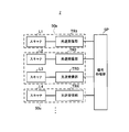
- the block diagram of a rider unit is shown.
- An example of arrangement of an individual scanner of a lidar unit is shown.
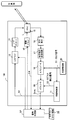
- the schematic structural example of an optical transmission / reception part is shown.
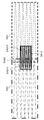
- the scan area corresponding to each scanner in a virtual irradiation surface is shown. It is the figure which clarified the irradiation area of the transmission light pulse by each scanner.
- the control device comprises a first irradiating unit for irradiating an electromagnetic wave, and the first irradiating unit so that a predetermined area is scanned by the electromagnetic wave irradiated by the first irradiating unit.
- a control unit configured to control the first region in the predetermined region, the first region being scanned by a second irradiation unit different from the first irradiation unit in the predetermined region;
- the first irradiation unit is controlled so that the electromagnetic wave is irradiated at an intensity lower than that of the second area which is an area other than the one area.
- the irradiation distance of the electromagnetic wave irradiated by the first irradiation unit is shorter than the irradiation distance of the electromagnetic wave irradiated by the second irradiation unit. According to this aspect, it is possible to give priority to the irradiation of the electromagnetic wave by the irradiation unit having a long distance for irradiating the electromagnetic wave (that is, including the far side as the detection target), and to preferably suppress the detection region from being narrowed.
- the irradiation area of the electromagnetic wave by the first irradiation unit is wider than the irradiation area of the electromagnetic wave by the second irradiation unit.
- the control device can prioritize the irradiation of the electromagnetic wave by the irradiation unit having the narrow irradiation area, and can preferably acquire the highly accurate detection result.
- the control unit controls the first irradiation unit such that the intensity of the electromagnetic wave is zero in the first region.
- the control device can suppress the irradiation of the electromagnetic waves by the plurality of irradiation units at the same position at the same timing, and can preferably satisfy the eye-safe standard while suppressing the decrease in detection accuracy.
- control unit is configured to use the first irradiation unit and the second irradiation unit in overlapping portions of the irradiation areas of the first irradiation unit and the second irradiation unit.
- a partial area to which electromagnetic waves may be simultaneously irradiated is specified as the first area.
- the control device can suitably limit the restricted region of the irradiation of the electromagnetic wave by the first irradiation unit.
- the control device includes a detection unit configured to detect an irradiation angle of at least one of the vertical direction and the horizontal direction of the first irradiation unit, and the control unit detects the irradiation angle.
- the timing at which the first region is irradiated with the electromagnetic wave is recognized based on the irradiation angle.
- the control device can appropriately recognize the timing of applying the electromagnetic wave to the first area by the first irradiation unit, and adjust the intensity of the electromagnetic wave to be applied to the first area.
- Control step of controlling the first irradiation unit, and the control step is for the first region scanned by the second irradiation unit different from the first irradiation unit in the predetermined region.
- the first irradiation unit is controlled such that the electromagnetic wave is irradiated at a lower intensity than a second area which is an area other than the first area in the predetermined area.
- the control device executes this control method to obtain good detection results without lowering the detection efficiency while satisfying the eye-safe criteria when the irradiation areas of the first irradiation unit and the second irradiation unit overlap. It becomes possible.
- a program executed by a computer that controls a first irradiation unit that irradiates an electromagnetic wave is configured to scan a predetermined area with the electromagnetic wave irradiated by the first irradiation unit.
- the control unit being scanned by the second irradiation unit different from the first irradiation unit in the predetermined area.
- the first irradiation unit is controlled such that the electromagnetic wave is irradiated at a lower intensity than the second area which is an area other than the first area in the predetermined area.
- the computer can obtain good detection results without lowering detection efficiency while satisfying the eye-safe criteria when the irradiation areas of the first irradiation unit and the second irradiation unit overlap. It becomes possible.
- the program is stored in a storage medium.
- FIG. 1 is a schematic configuration of a measurement system 100 according to the present embodiment.
- the measurement system 100 is a system for performing measurement for automatic driving of a vehicle (not shown), and mainly includes the input unit 1, the storage unit 3, the sensor unit 2, the notification unit 4, the communication unit 5, and control And 6 are provided.
- the control unit 6 and the other elements are configured to be capable of data communication based on a predetermined communication protocol.
- the input unit 1 is a button operated by a user, a touch panel, a remote controller, a voice input device, or the like, and receives various inputs such as switching between automatic operation and manual operation.
- the sensor unit 2 includes an internal sensor that detects the state of the vehicle and an external sensor that recognizes the surrounding environment of the vehicle.
- the sensor unit 2 includes a lidar (Light Detection and Ranging) or Laser Illuminated Detection And Ranging unit 7.
- the lidar unit 7 discretely measures the distance to an object present in the external world by emitting a pulse laser which is an electromagnetic wave to a predetermined angle range in the horizontal direction and the vertical direction, and indicates the position of the object Generate 3D point cloud information.
- the lidar unit 7 has a scanning unit (scanner) for emitting laser light while changing the irradiation direction, and for receiving the reflected light (scattered light) of the irradiated laser light.
- the rider unit 7 has a plurality of scanners installed in different orientations. An example of the configuration of the rider unit 7 will be described later with reference to FIGS.
- the lidar unit 7 is an example of the “control device” in the present invention.
- the storage unit 3 stores programs executed by the control unit 6 and information necessary for the control unit 6 to execute predetermined processing.
- the storage unit 3 stores the map DB 20.
- the map DB 20 may be used for navigation at the time of manual operation of the vehicle, or may be used for operation control of the vehicle at the time of automatic operation of the vehicle.
- the map DB 20 includes, in addition to road data and facility information, feature information on features to be detected by the rider unit 7 and the like.
- the notification unit 4 is, for example, a display, a speaker, or the like that outputs based on the control of the control unit 6.
- the communication unit 5 performs data communication with an external device based on the control of the control unit 6.
- the control unit 6 includes a CPU or the like that executes a program, and controls the entire measurement system 100.
- the control unit 6 may be an electronic control unit (ECU) that automatically controls the driving of the vehicle, and is a CPU of an in-vehicle apparatus that transmits a control signal instructing the ECU to switch between automatic driving and manual driving. May be In another example, the control unit 6 may be configured as part of the rider unit 7. In addition, the control unit 6 may perform the vehicle position estimation with high accuracy based on the output of the sensor unit 2 and the map DB 20.
- ECU electronice control unit
- the control unit 6 may perform the vehicle position estimation with high accuracy based on the output of the sensor unit 2 and the map DB 20.
- FIG. 2 shows a block diagram of the rider unit 7.
- the rider unit 7 is a TOF (Time Of Flight) rider, and performs ranging and detection of an object present around the vehicle.
- the rider unit 7 is used, for example, as a part of an advanced driving support system for the purpose of assisting the recognition of the surrounding environment of the vehicle.
- the rider unit 7 mainly includes a plurality of scanners (L1 to L4,%), A plurality of light transmitting / receiving units (TR1 to TR4,...), And a signal processing unit SP.
- the scanner L emits a laser pulse (hereinafter also referred to as “transmission light pulse”) in a range of predetermined horizontal angle and vertical angle.
- the scanner L emits transmission light pulses for each segment obtained by equally dividing the above-mentioned horizontal angle.
- the light transmission / reception unit TR relates to the light reception intensity for each segment generated by receiving the reflected light of the transmission light pulse (hereinafter also referred to as “reception light pulse”) within a predetermined period after the transmission light pulse is emitted.
- a signal also referred to as “segment signal Sseg” is output to the signal processing unit SP.
- the signal processing unit SP is a point cloud information indicating a set of the distance and the angle of the object with respect to each point of the object to be irradiated with the transmission light pulse based on the segment signal Sseg for each segment received from the light transmitting / receiving unit TR Output
- the scanner L and the light transmitting / receiving unit TR are accommodated in the scanner accommodating unit 50 (50a to 50c,).
- the scanner accommodation unit 50 accommodates one or more sets of the scanner L and the light transmitting / receiving unit TR.
- the scanner accommodation unit 50a accommodates the scanner L1 and the light transmitting / receiving unit TR1
- the scanner accommodation unit 50b accommodates the scanners L2 and L3 and the light transmitting / receiving units TR2 and TR3
- the scanner accommodating unit 50c accommodates the scanner L4 and the light transmitting / receiving unit TR4.
- An orientation sensor for example, a 3-axis acceleration sensor or a strain gauge for detecting the orientation of the scanner accommodation unit 50 in each of the scanner accommodation units 50, and an adjustment mechanism for adjusting the direction of the scanner accommodation unit 50. Etc. may be provided.
- the attitude sensor and the adjustment mechanism may be provided for each scanner L instead of being provided for each scanner housing unit 50.
- FIG. 3 shows an arrangement example of the individual scanners L of the rider unit 7.
- hatched fan-shaped areas indicate scan areas (scan areas) SA1 to SA13 which are areas to which transmission light pulses emitted from the corresponding scanners L1 to L13 are irradiated.
- scan areas SA1 to SA13 are also simply referred to as "scan area SA".
- the vehicle is provided with 13 scanners L (L1 to L13), and the scanners L1 to L4 and L13 are provided in the direction in which the front of the vehicle is a scan area, and the scanners L5 and L6 are The left side of the vehicle is provided as the scan area.
- the scanners L7 and L8 are provided in the direction in which the right side of the vehicle is the scan area, and the scanners L9 to L12 are provided in the direction in which the rear of the vehicle is the scan area.
- each scanner L has different horizontal viewing angles (i.e., an angle range for scanning in the horizontal direction) and maximum ranging distances (i.e., distances for applying an electromagnetic wave).
- the scanners L5 to L8 directed to the side of the vehicle have the widest horizontal viewing angle " ⁇ 2" among all the scanners L1 to L13, and have the shortest maximum ranging distance "D2 "have.
- the scanner L13 directed to the front of the vehicle has the narrowest horizontal viewing angle " ⁇ 3" among all the scanners L1 to L13, and has the longest maximum distance measurement distance "D3". .
- the scanners L1 to L4 directed to the front of the vehicle and the scanners L9 to L12 directed to the rear of the vehicle have a horizontal viewing angle “ ⁇ 1” smaller than the angle ⁇ 2 and larger than the angle ⁇ 3 (ie, ⁇ 3).
- the maximum distance measurement distance “D1” (that is, D2 ⁇ D1 ⁇ D3) which has a relationship of ⁇ 1 ⁇ 2 and is longer than the distance D2 and shorter than the distance D3.
- the scan area SA corresponding to each scanner L includes an area overlapping with the scan area SA corresponding to the adjacent scanner L (also referred to as “overlap area DA”).
- the scan area SA2 corresponding to the scanner L2 includes a scan area SA1 corresponding to the scanner L1, a scan area SA3 corresponding to the scanner L3, and an overlap area DA to the scan area SA13 corresponding to the scanner L13.
- the lidar unit 7 in the present embodiment controls the emission of transmission light pulses by the respective scanners L so that the transmission light pulses from the plurality of scanners L are not emitted in the overlapping area DA.
- FIG. 4 shows a schematic configuration example of the light transmitting / receiving unit TR.
- the light transmitting / receiving unit TR mainly uses the synchronization control unit 11, the LD driver 12, the laser diode 13, the angle sensor 14, the drive driver 15, the light receiving element 16, and current / voltage conversion.
- a circuit (transimpedance amplifier) 17, an A / D converter 18, a segmentor 19, and a crystal oscillator 20 are included.
- the crystal oscillator 20 outputs a pulse-like clock signal “S1” to the synchronization control unit 11 and the A / D converter 18.
- the synchronization control unit 11 outputs a pulse-like trigger signal “S2” to the LD driver 12.
- the synchronization control unit 11 also outputs a segment extraction signal “S3”, which determines the timing at which the segmenter 19 described later extracts the output of the A / D converter 18, to the segmentator 19.
- the LD driver 12 supplies a pulse current to the laser diode 13 in synchronization with the trigger signal S2 input from the synchronization control unit 11. Further, in the present embodiment, the LD driver 12 switches the presence or absence of the supply of the pulse current to the laser diode 13 based on the control signal supplied from the signal processing unit SP.
- the laser diode 13 is, for example, an infrared pulse laser, and emits a light pulse based on the pulse current supplied from the LD driver 12.
- the scanner L is, for example, a MEMS mirror, scans a transmission light pulse emitted from the laser diode 13, and receives a reception light pulse as return light reflected by an object irradiated with the emitted transmission light pulse. Lead to 16.
- the scanner L is provided with an angle sensor 14 for detecting the emission direction of the scanner L.
- an angle sensor 14 for detecting the emission direction of the scanner L.
- the scanner L is a MEMS mirror
- a piezo sensor that detects the position of the MEMS mirror in the horizontal direction and the vertical direction is provided as the angle sensor 14.
- the angle sensor 14 supplies the control unit 6 with an angle detection signal “S4” related to the detection angle of the scanner L.
- the drive driver 15 supplies a drive signal for driving the scanner L in the horizontal direction and the vertical direction to the scanner L based on the control of the signal processing unit SP.
- the drive driver 15 supplies a drive signal based on a predetermined resonance frequency to the scanner L using a resonance phenomenon in scanning in the horizontal direction.
- the drive driver 15 supplies a drive signal that becomes a triangular wave (sawtooth wave) to the scanner L in order to drive at non-resonance in the vertical scanning.
- the scanner L and the light transmitting / receiving unit TR corresponding thereto are examples of the “irradiation unit” in the present invention.
- the angle sensor 14 is an example of the “detection unit” in the present invention.
- the light receiving element 16 is, for example, an avalanche photodiode, and generates a weak current according to the reflected light from the object guided by the scanner L, that is, the light quantity of the received light pulse.
- the light receiving element 16 supplies the generated weak current to the current-voltage conversion circuit 17.
- the current-voltage conversion circuit 17 amplifies the weak current supplied from the light receiving element 16 and converts it into a voltage signal, and inputs the converted voltage signal to the A / D converter 18.
- the A / D converter 18 converts the voltage signal supplied from the current-voltage conversion circuit 17 into a digital signal based on the clock signal S1 supplied from the crystal oscillator 20 and supplies the converted digital signal to the segmentor 19.
- the segmenter 19 generates, as a segment signal Sseg, a digital signal that is an output of the A / D converter 18 in a period in which the segment extraction signal S3 is asserted.
- the segmenter 19 supplies the generated segment signal Sseg to the signal processing unit SP.
- the signal processing unit SP controls the drive driver 15 to drive the respective scanners L so as to scan the inside of the scan area SA, which is a predetermined area, with the transmission light pulse. Further, the signal processing unit SP is configured to control a control signal for controlling emission of a transmission light pulse by each scanner L based on scan area information “IS” described later and an angle detection signal S4 supplied from the angle sensor 14. It supplies to driver 12 grade. Further, the signal processing unit SP generates point group information indicating the distance and the angle of the object for each light transmission / reception unit TR based on the segment signal Sseg transmitted from each light transmission / reception unit TR.
- the signal processing unit SP detects a peak from the waveform of the segment signal Sseg, and estimates an amplitude and a delay time corresponding to the detected peak. Then, the signal processing unit SP determines, among the peaks of the waveform indicated by the segment signal Sseg, the information of the distance corresponding to the delay time of the peak for which the estimated amplitude is a predetermined threshold or more and the information of the angle corresponding to the target segment. Is generated as information of each point constituting point cloud information.
- the scan area information IS is information on the scan area SA to which the transmission light pulse is irradiated by each scanner L of the rider unit 7, and the memory or storage unit 3 included in the rider unit 7 can be referred to for example. Is stored in In the present embodiment, the scan area information IS includes information by which the signal processing unit SP can specify the overlapping area DA for each adjacent scanner L.
- the scan area information IS may be generated in advance based on the actual measurement value of the measurement regarding the scan area SA of each scanner L executed after the rider unit 7 is attached to the vehicle, and the vertical viewing angle and horizontal viewing angle of each scanner L , And may be generated based on theoretical calculation processing in consideration of the installation position on the vehicle, the installation direction, and the like.
- the signal processing unit SP is a posture of the scanner accommodation unit 50 that accommodates each scanner L based on the output of the posture detection sensor for each scanner L of the rider unit 7 (that is, the installation position and installation direction on the vehicle).
- the scan area information IS may be appropriately generated and updated based on the identified posture information and the information of the vertical viewing angle and the horizontal viewing angle of each scanner L previously stored in the storage unit 3 or the like.
- emission control of the transmission light pulse by each scanner L in the overlapping area DA will be described.
- the signal processing unit SP causes only one scanner L of the scanners L including the overlapping area DA in the scan area SA to emit light, and the other scanners L not to emit light.
- the signal processing unit SP suitably generates point cloud information on peripheral objects while surely satisfying the eye-safe condition.
- FIG. 5 shows scan areas SA2, SA3 and SA13 corresponding to the scanners L2, L3 and L13 on a virtual irradiation surface (virtual irradiation surface) separated by a predetermined distance in front of the vehicle.
- the scanning line (scanning locus) of the scanner L2 is indicated by an alternate long and short dashed line
- the scanning line of the scanner L3 is indicated by a broken line
- the scanning line of the scanner L13 is indicated by a solid line.
- the scan area SA2 and the scan area SA3, the scan area SA2 and the scan area SA13, and the scan area SA3 and the scan area SA13 overlap to form an overlap area DA.
- “DA23” indicates an overlapping area DA between scan area SA2 and scan area SA3
- “DA213” indicates an overlapping area DA between scan area SA2 and scan area SA13
- “DA313” indicates a scan area
- An overlap area DA between SA3 and scan area SA13 is shown.
- the signal processing unit SP specifies the overlapping areas DA23, DA213, and DA313 by referring to the scan area information IS, and any one of the scanners L2, L3, and L13 in the overlapping areas DA23, DA213, and DA313. Only one is lit.
- the signal processing unit SP emits light without any limitation on the scanner L where the maximum distance measurement distance is long (that is, the distance is included in the scan area SA). Limits the light emission of the scanner L which is short (ie, the vicinity of the vehicle is taken as the scan area SA). Thereby, the signal processing unit SP performs emission control of the transmission light pulse so as to surely satisfy the eye-safe standard without narrowing the detection range of the lidar unit 7 substantially.
- FIG. 6A is a view clearly showing the irradiation area of the transmission light pulse emitted by the scanner L2 in the scan area SA2
- FIG. 6B shows the irradiation of the transmission light pulse emitted by the scanner L3 in the scan area SA3.
- FIG. 6C is a diagram clearly showing the area
- FIG. 6C is a diagram clearly showing the irradiation area of the transmission light pulse emitted by the scanner L13 in the scan area SA13.
- the transmission light pulse from the scanner L2 is not irradiated to the area corresponding to the overlapping area DA213.
- the transmission light pulse from the scanner L3 is not irradiated to the area corresponding to the overlapping area DA313.
- the transmission light pulse from the scanner L13 is emitted without limitation in the entire area.
- the signal processing unit SP causes the transmission light pulse of the scanner L13 having the longest distance measurement distance to be longer than that of the scanner L2 and the scanner L3 to emit light without limitation. Stop emission of the transmission light pulse.
- the signal processing unit SP preferably detects an object in the scan area SA13 of the scanner L13 with a long maximum distance measurement distance while preventing overlapping emission of transmission light pulses in the overlap area DA. It is possible to prevent the narrowing of the detection range by the rider unit 7.
- the signal processing unit SP transmits the transmission light pulse to one predetermined scanner L (in this case, the scanner L3). Limit outgoing radiation.
- the signal processing unit SP causes the scanner L2 to emit transmission pulse light without limitation on the overlapping area DA23 and limits the emission of transmission pulse light to the scanner L3. ing.
- the signal processing unit SP transmits the transmission light pulse without limitation for the scanner L having a narrow scan area SA (that is, a small horizontal viewing angle).
- the light emission may be limited to the scanner L having a wide-angle scan area.
- the signal processing unit SP is caused by the light emission restriction of the scanner L when the detection accuracy in which the scanner L with a narrow scan area SA can obtain the same area as the scanner L with a wide scan area SA is higher. It is possible to preferably suppress the decrease in detection accuracy.
- the signal processing unit SP refers to the scan area information IS to refer to a horizontal section (also referred to as a “horizontal limit section”) of the overlapping area DA 213 which is an area to which the emission of the transmission light pulse by the scanner L2 should be limited (stopped). And vertical intervals (also referred to as “vertically limited intervals”).
- the signal processing unit SP recognizes a section from the position “c1” to the position “c2” as the horizontal restricted section of the overlapping area DA213, and a position “h1” to the position “h1” as the vertical restricted section of the overlapping area DA213. Recognize the section up to "h2".
- the signal processing unit SP monitors the transition of the current scanning position by the scanner L2. Then, when the signal processing unit SP determines that the current scanning position belongs to the horizontal restriction section from the position c1 to the position c2 and belongs to the vertical restriction section from the position h1 to the position h2, By transmitting a predetermined control signal, the emission of the transmission light pulse by the laser diode 13 is stopped. As described above, the signal processing unit SP preferably stops the emission of the transmission light pulse in the target overlapping area DA without changing the drive control of the scanner L by controlling the light emission of the laser diode 13. it can. Therefore, even when the target scanner L performs scanning using a resonance phenomenon in at least one of horizontal scanning and vertical scanning, the signal processing unit SP preferably applies the transmission light pulse in the overlapping area DA of the target. Can be stopped.
- the signal processing unit SP may set the above-described virtual irradiation surface based on the shortest maximum distance measurement distance (the distance D2 in the example of FIG. 3) among all the scanners L.
- the signal processing unit SP sets the above-described virtual irradiation plane based on the shortest maximum distance measurement distance (the distance D1 in the example of FIG. 5) among the scanners L that form the target overlapping area DA. Good. By doing this, the signal processing unit SP can perform emission control of the transmission light pulse by each scanner L so that the eye-safe standard can be surely adhered to.
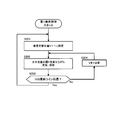
- FIG. 7 is a flowchart showing the procedure of light emission control for each scanner L.
- the signal processing unit SP executes the process shown in FIG. 7 for each combination of each scanner L and the light transmitting / receiving unit TR.
- the signal processing unit SP determines, for the target scanner L, whether there is an overlap of the scan area SA with another scanner L (step S101).
- the signal processing unit SP refers to the scan area information IS to determine whether the overlapping area DA is present between the scan area SA of the target scanner L and the scan area SA of the adjacent scanner L.
- the signal processing unit SP performs normal light emission processing for the target scanner L.
- the first light emission process which is the first light emission process, is performed (step S105). The first light emission process will be described with reference to FIG.
- the signal processing unit SP detects the other scanner L as a detection target (that is, the maximum ranging distance). Determines whether the overlapping area DA exists (step S102). Then, the signal processing unit SP emits light of the transmission light pulse by the target scanner L in the overlapping area DA, when there is an overlapping area DA in which the other scanner L detects the distant side (step S102; Yes).
- the second light emission process which is a process of restricting the light emission is executed (step S103). The second light emitting process will be described with reference to FIG.
- the signal processing unit SP has a predetermined priority higher than that of the other scanner L. It is determined whether the overlapping area DA exists (step S104).
- the above-mentioned priority is, for example, the priority of light emission between the scanners L where the maximum distance measurement distance is equal, and the lower the priority is as the scanner L whose scanning area is wide (that is, the horizontal viewing angle is large) It may be set as such, or may be set to have higher priority as the scanner L has a direction closer to the front of the vehicle as the scan area SA. In still another example, the above-mentioned priority may be a priority defined based on a personal method.
- step S104 when there is an overlapping area DA in which the other scanner L has a predetermined higher priority than the other scanner L (step S104; Yes), the signal processing unit SP transmits a light pulse transmitted by the target scanner L in the overlapping area DA. A second light emission process is performed to limit the light emission (step S103). On the other hand, the signal processing unit SP restricts the emission of the transmission light pulse by the target scanner L when there is no overlapping area DA in which the other scanner L has a predetermined priority higher (Step S104; No) It is determined that it is not necessary to perform the first light emission process (step S105).
- FIG. 8 is a flowchart showing the procedure of the first light emission process performed in step S105 of FIG.
- the scanning position in the vertical direction on the scanning area SA is referred to as “vertical scanning position V”
- the scanning position in the horizontal direction on the scanning area SA is referred to as “horizontal scanning position H”.
- the vertical scanning position V on the top level in the scan area SA is taken as the first line.
- step S203 when the current vertical scanning position V is not the final line position (step S203; No), the signal processing unit SP adds the vertical scanning position V by one line (step S204), and the vertical scanning position V is added again.
- step S202 is performed.
- step S203 when the signal processing unit SP determines that the vertical scanning position V is the final line position (step S203; Yes), the signal processing unit SP returns to step S201 again and sets the vertical scanning position V to the first line.
- FIG. 9 is a flowchart showing the procedure of the second light emission process performed in step S103 of FIG.
- the signal processing unit SP determines whether the vertical scanning position V is within the vertical restriction section recognized in step S301 (step S303).
- the signal processing unit SP detects the target scanner L when the horizontal scanning position H is at the horizontal scanning position H where the horizontal restriction zone is out.
- the light emission of the transmission light pulse and the light reception of the reception light pulse are performed (step S304).
- the signal processing unit SP estimates the current horizontal scanning position H based on the angle detection signal S4 supplied from the angle sensor 14, and when the estimated horizontal scanning position H is within the horizontal limit section, the laser diode The LD driver 12 is controlled so as not to emit light. Thereby, the signal processing unit SP reliably suppresses simultaneous emission of transmission light pulses by the plurality of scanners L in the overlapping area DA.
- step S303 when the vertical scanning position V is out of the vertical restriction section (step S303; No), the signal processing unit SP performs all of the target vertical scanning positions V as in step S202 of FIG. Emission of a transmission light pulse and reception of a reception light pulse by the target scanner L are performed for the horizontal scanning position H (step S306).
- the signal processing unit SP determines whether the current vertical scanning position V is the final line position (that is, the lowermost position of the scan area SA) (step S305). Then, when the current vertical scanning position V is not the final line position (step S305; No), the signal processing unit SP adds the vertical scanning position V by one line (step S307), and the vertical scanning position V is added again. The process of step S303 is performed. On the other hand, when the signal processing unit SP determines that the vertical scanning position V is the final line position (step S305; Yes), the signal processing unit SP returns to step S302 again, and sets the vertical scanning position V to the first line.
- the lidar unit 7 includes a pair of the light transmitting / receiving unit TR and the scanner L (first irradiating unit) that irradiates laser light, and the predetermined area is the light transmitting / receiving unit TR and the scanner L A signal processing unit SP that controls the light transmitting / receiving unit TR and the scanner L so as to be scanned by the irradiated laser light.
- the signal processing unit SP is an overlapping area DA (a scanning unit SA) which is scanned by the light transmitting / receiving unit TR different from the light transmitting / receiving unit TR and the scanner L and the scanner L (second irradiating unit).
- the light transmitting / receiving unit TR and the scanner L are provided so that the laser light is irradiated at a lower intensity than the area (second area) other than the overlapping area DA in the scan area SA.
- the rider unit 7 can preferably output point cloud information on peripheral objects while surely satisfying the eye-safe condition.
- the signal processing unit SP causes the laser diode 13 to emit light instead of stopping the light emission of the laser diode 13 when the horizontal scanning position H exists in the horizontal limited section in step S304 of the second light emission processing of FIG. 9.
- the intensity may be lower than the normal intensity.
- the signal processing unit SP is configured such that the total value of the intensity of the transmission light pulse emitted by the scanner L emitted by the other scanner L in the overlapping area DA of interest is equal to or less than the predetermined threshold serving as the upper limit of eye safety.
- the rider unit 7 can suitably generate point cloud information on an object around the vehicle while satisfying the eye-safe standard.
- the signal processing unit SP performs irradiation control with the other scanner L instead of performing light emission restriction of the target scanner L in the entire area of the overlapping area DA where the irradiation range overlaps with the other scanners L.
- the emission limitation of the target scanner L may be performed on a part of the overlapping area DA in which the ranges overlap and which may emit light simultaneously.
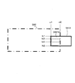
- FIG. 10 is a diagram for describing an outline of the second light emission process in the present modification.
- FIG. 10 similarly to FIG. 6A, the positional relationship between the scan area SA2 and the scan area SA2 overlapping the scan area SA2 on a certain irradiation surface is shown.
- the signal processing unit SP recognizes the overlapping area DA213 as an area in which the scan area SA2 of the scanner L2 overlaps with the scan area SA13 of the scanner L13. Thereafter, the signal processing unit SP recognizes an area in the overlapping area DA213 where the scanner L2 and the scanner L13 may emit the transmission light pulse at the same position at the same timing. For example, in the case where the scanning cycle for each of the scan areas SA of the scanner L2 and the scanner L13 is synchronized, there is no possibility that the transmission light pulse is irradiated to the same position at the same timing for the upper area and the lower area in the overlapping area DA213. .
- step S301 of the vertical sections of the overlapping area DA213 from the position h1 to the position h2, the signal processing unit SP removes from the position h3 excluding the sections corresponding to the upper area and the lower area of the overlapping area DA213.
- the vertical section up to the position h4 is regarded as the vertical restriction section.
- the information of the above-described vertical restricted section is recorded in advance in the scan area information IS or the like, for example, for each combination of scanners L in which the overlapping area DA occurs.
- the signal processing unit SP can minimize the area in which the light emission restriction is performed by the target scanner L.
- the signal processing unit SP defines a section in the horizontal section of the overlapping area DA 213 in which transmission light pulses may be emitted simultaneously at the same position at the same timing as the horizontal limited section. May be
- the control unit 6 may execute part of the processing of the signal processing unit SP.
- the scan area information IS is recorded in the storage unit 3, and the control unit 6 receives the angle detection signal S4 supplied from the angle sensor 14 from the lidar unit 7, and the scan area information IS.
- the controller 6 determines that the horizontal scanning position H exists in the horizontal restriction section in step S304, the controller 6 instructs the lidar to stop the light emission of the laser diode 13 as the lidar.
- the signal processing unit SP transmits the signal to the signal processing unit SP of the unit 7, and stops the light emission of the laser diode 13 according to the instruction signal.
- the signal processing unit SP and the control unit 6 may be the same device.
- the signal processing unit SP of the rider unit 7 is electrically connected to the input unit 1, the storage unit 3, the notification unit 4, the communication unit 5 and the like, and controls the entire measurement system 100.
Landscapes
- Physics & Mathematics (AREA)
- Engineering & Computer Science (AREA)
- General Physics & Mathematics (AREA)
- Electromagnetism (AREA)
- Computer Networks & Wireless Communication (AREA)
- Radar, Positioning & Navigation (AREA)
- Remote Sensing (AREA)
- Optics & Photonics (AREA)
- Optical Radar Systems And Details Thereof (AREA)
Abstract
ライダユニット7は、レーザ光を照射する光送受信部TR及びスキャナL(第1照射部)と、所定領域が光送受信部TR及びスキャナLによって照射されたレーザ光によって走査されるように、光送受信部TR及びスキャナLを制御する信号処理部SPと、を備える。そして、信号処理部SPは、上記所定領域に相当するスキャンエリアSAのうち、上記の光送受信部TR及びスキャナLと異なる光送受信部TR及びスキャナL(第2照射部)によって走査される重複エリアDA(第1領域)については、スキャンエリアSA内の重複エリアDA以外の領域(第2領域)よりも低い強度でレーザ光が照射されるように、光送受信部TR及びスキャナL(第1照射部)を制御する。
Description
本発明は、電磁波を照射する照射部の制御技術に関する。
従来から、電磁波を照射する照射部を複数配置するシステムが開示されている。例えば、特許文献1には、検出領域が一部重複するように距離測定手段を複数配置した場合に、これらの距離測定手段のそれぞれの距離測定を、当該距離測定手段の検出領域と一部が重なる他の距離測定手段が距離測定を実施していないタイミングで実行する技術が開示されている。
電磁波を照射する照射部を複数配置した場合に、重複する検出領域の重複部分に同時に電磁波を照射すると、当該照射部を備えた製品が満たすべき条件(例えば、アイセーフ(即ち眼に対する安全性))が満たせなくなる可能性がある。一方、特許文献1のように、照射部の照射タイミングを時分割により重複しないように設定した場合には、検出効率が低下するなどの問題が生じる。
本発明は、上記のような課題を解決するためになされたものであり、電磁波を照射する照射部が複数存在する場合に、所定の条件を満たしつつ良好な検出結果を得ることが可能な制御装置を提供することを主な目的とする。
請求項に記載の発明は、制御装置であって、電磁波を照射する第1照射部と、所定領域が前記第1照射部によって照射された電磁波によって走査されるように、前記第1照射部を制御する制御部と、を備え、前記制御部は、前記所定領域のうち、前記第1照射部とは異なる第2照射部によって走査される第1領域については、前記所定領域内の前記第1領域以外の領域である第2領域よりも低い強度で前記電磁波が照射されるように、前記第1照射部を制御する。
また、請求項に記載の発明は、電磁波を照射する第1照射部を制御する制御装置が実行する制御方法であって、所定領域が前記第1照射部によって照射された電磁波によって走査されるように、前記第1照射部を制御する制御工程を有し、前記制御工程は、前記所定領域のうち、前記第1照射部とは異なる第2照射部によって走査される第1領域については、前記所定領域内の前記第1領域以外の領域である第2領域よりも低い強度で前記電磁波が照射されるように、前記第1照射部を制御する。
また、請求項に記載の発明は、電磁波を照射する第1照射部を制御するコンピュータが実行するプログラムであって、所定領域が前記第1照射部によって照射された電磁波によって走査されるように、前記第1照射部を制御する制御部として前記コンピュータを機能させ、前記制御部は、前記所定領域のうち、前記第1照射部とは異なる第2照射部によって走査される第1領域については、前記所定領域内の前記第1領域以外の領域である第2領域よりも低い強度で前記電磁波が照射されるように、前記第1照射部を制御する。
本発明の好適な実施形態によれば、制御装置は、電磁波を照射する第1照射部と、所定領域が前記第1照射部によって照射された電磁波によって走査されるように、前記第1照射部を制御する制御部と、を備え、前記制御部は、前記所定領域のうち、前記第1照射部とは異なる第2照射部によって走査される第1領域については、前記所定領域内の前記第1領域以外の領域である第2領域よりも低い強度で前記電磁波が照射されるように、前記第1照射部を制御する。この態様によれば、制御装置は、第1照射部と第2照射部との照射領域が重なる場合に、アイセーフ等の所定の基準を満たしつつ、検出効率を下げずに良好な検出結果を得ることが可能となる。
上記制御装置の一態様では、前記第1照射部により照射される電磁波の照射距離は、前記第2照射部により照射される前記電磁波の照射距離より短い。この態様によれば、電磁波を照射する距離が長い(即ち遠方を検出対象に含む)照射部による電磁波の照射を優先させ、検出領域が狭まるのを好適に抑制することができる。
上記制御装置の他の一態様では、前記第1照射部による電磁波の照射領域は、前記第2照射部による電磁波の照射領域よりも広角である。この態様によれば、制御装置は、狭い照射領域を有する照射部による電磁波の照射を優先させ、高精度な検出結果を好適に取得ことができる。
上記制御装置の他の一態様では、前記制御部は、前記第1領域について、前記電磁波の強度が0となるように前記第1照射部を制御する。この態様により、制御装置は、同一位置に同一のタイミングで複数の照射部による電磁波の照射を抑制し、検出精度の低下を抑制しつつアイセーフの基準を好適に満たすことができる。
上記制御装置の他の一態様では、前記制御部は、前記第1領域について、前記電磁波の強度が0となるように前記第1照射部を制御する。この態様により、制御装置は、同一位置に同一のタイミングで複数の照射部による電磁波の照射を抑制し、検出精度の低下を抑制しつつアイセーフの基準を好適に満たすことができる。
上記制御装置の他の一態様では、前記制御部は、前記第1照射部と前記第2照射部との照射領域の重複部分のうち、前記第1照射部と前記第2照射部とにより前記電磁波が同時に照射される可能性がある一部の領域を、前記第1領域として特定する。この態様により、制御装置は、第1照射部による電磁波の照射の制限領域を好適に限定することができる。
上記制御装置の他の一態様では、制御装置は、前記第1照射部の垂直方向又は水平方向の少なくとも一方の照射角度を検出する検出部を備え、前記制御部は、前記検出部が検出した照射角度に基づき、前記第1照射部により前記第1領域に前記電磁波を照射するタイミングを認識する。この態様により、制御装置は、第1照射部により第1領域に電磁波を照射するタイミングを好適に認識し、第1領域に照射させる電磁波の強度を調整することができる。
本発明の他の好適な実施形態によれば、電磁波を照射する第1照射部を制御する制御装置が実行する制御方法であって、所定領域が前記第1照射部によって照射された電磁波によって走査されるように、前記第1照射部を制御する制御工程を有し、前記制御工程は、前記所定領域のうち、前記第1照射部とは異なる第2照射部によって走査される第1領域については、前記所定領域内の前記第1領域以外の領域である第2領域よりも低い強度で前記電磁波が照射されるように、前記第1照射部を制御する。制御装置は、この制御方法を実行することで、第1照射部と第2照射部との照射領域が重なる場合に、アイセーフの基準を満たしつつ、検出効率を下げずに良好な検出結果を得ることが可能となる。
本発明のさらに別の好適な実施形態によれば、電磁波を照射する第1照射部を制御するコンピュータが実行するプログラムであって、所定領域が前記第1照射部によって照射された電磁波によって走査されるように、前記第1照射部を制御する制御部として前記コンピュータを機能させ、前記制御部は、前記所定領域のうち、前記第1照射部とは異なる第2照射部によって走査される第1領域については、前記所定領域内の前記第1領域以外の領域である第2領域よりも低い強度で前記電磁波が照射されるように、前記第1照射部を制御する。コンピュータは、このプログラムを実行することで、第1照射部と第2照射部との照射領域が重なる場合に、アイセーフの基準を満たしつつ、検出効率を下げずに良好な検出結果を得ることが可能となる。好適には、上記プログラムは、記憶媒体に記憶される。
以下、図面を参照して本発明の好適な実施例について説明する。
[全体構成]
図1は、本実施例に係る計測システム100の概略構成である。計測システム100は、図示しない車両の自動運転用の計測を行うシステムであって、主に、入力部1と、記憶部3と、センサ部2と、報知部4と、通信部5と、制御部6とを備える。制御部6と他の要素とは、所定の通信プロトコルに基づきデータ通信が可能に構成されている。
図1は、本実施例に係る計測システム100の概略構成である。計測システム100は、図示しない車両の自動運転用の計測を行うシステムであって、主に、入力部1と、記憶部3と、センサ部2と、報知部4と、通信部5と、制御部6とを備える。制御部6と他の要素とは、所定の通信プロトコルに基づきデータ通信が可能に構成されている。
入力部1は、ユーザが操作するためのボタン、タッチパネル、リモートコントローラ、音声入力装置等であり、自動運転と手動運転との切替えなどの種々の入力を受け付ける。
センサ部2は、車両の状態を検出する内界センサ及び車両の周辺環境を認識するための外界センサから構成される。センサ部2は、ライダ(Lidar:Light Detection and Ranging、または、Laser Illuminated Detection And Ranging)ユニット7を含んでいる。
ライダユニット7は、水平方向および垂直方向の所定の角度範囲に対して電磁波であるパルスレーザを出射することで、外界に存在する物体までの距離を離散的に測定し、当該物体の位置を示す3次元の点群情報を生成する。この場合、ライダユニット7は、照射方向を変えながらレーザ光を出射し、かつ、照射したレーザ光の反射光(散乱光)を受光するための走査部(スキャナ)を有する。本実施例では、ライダユニット7は、異なる向きに設置された複数のスキャナを有する。ライダユニット7の構成例については、図2~図4を参照して後述する。ライダユニット7は、本発明における「制御装置」の一例である。
記憶部3は、制御部6が実行するプログラムや、制御部6が所定の処理を実行するのに必要な情報を記憶する。本実施例では、記憶部3は、地図DB20を記憶する。地図DB20は、車両の手動運転時におけるナビゲーションに用いられるものであってもよく、また、車両の自動運転時における車両の運転制御に用いられるものであってもよい。地図DB20には、道路データや施設情報の他、ライダユニット7による検出対象となる地物に関する地物情報などを含んでいる。
報知部4は、例えば、制御部6の制御に基づき出力を行うディスプレイやスピーカ等である。通信部5は、制御部6の制御に基づき外部装置とデータ通信を行う。
制御部6は、プログラムを実行するCPUなどを含み、計測システム100の全体を制御する。制御部6は、車両の運転を自動制御するECU(Electronic Control Unit)であってもよく、当該ECUに自動運転と手動運転との切り替えを指示する制御信号を送信する車載機のCPU等であってもよい。他の例では、制御部6は、ライダユニット7の一部として構成されてもよい。また、制御部6は、センサ部2の出力及び地図DB20に基づき、高精度な自車位置推定を行うものであってもよい。
[ライダユニットの構成例]
次に、ライダユニット7の構成例について説明する。図2は、ライダユニット7のブロック図を示す。ライダユニット7は、TOF(Time Of Flight)方式のライダであって、車両周辺に存在する物体の測距や検知を行う。ライダユニット7は、例えば、先進運転支援システムの一部として、車両の周辺環境認識補助の目的で用いられる。ライダユニット7は、主に、複数のスキャナ(L1~L4、…)と、複数の光送受信部(TR1~TR4、…)と、信号処理部SPと、を有する。なお、以下の説明においては、スキャナ(L1~L4、…)の各々を区別しない場合には単に「スキャナL」と記し、光送受信部(TR1~TR4、…)の各々を区別しない場合には単に「光送受信部TR」と記す。
次に、ライダユニット7の構成例について説明する。図2は、ライダユニット7のブロック図を示す。ライダユニット7は、TOF(Time Of Flight)方式のライダであって、車両周辺に存在する物体の測距や検知を行う。ライダユニット7は、例えば、先進運転支援システムの一部として、車両の周辺環境認識補助の目的で用いられる。ライダユニット7は、主に、複数のスキャナ(L1~L4、…)と、複数の光送受信部(TR1~TR4、…)と、信号処理部SPと、を有する。なお、以下の説明においては、スキャナ(L1~L4、…)の各々を区別しない場合には単に「スキャナL」と記し、光送受信部(TR1~TR4、…)の各々を区別しない場合には単に「光送受信部TR」と記す。
スキャナLは、所定の水平角及び垂直角の範囲においてレーザパルス(以下、「送信光パルス」とも呼ぶ。)を出射する。スキャナLは、上述の水平角を等角度により区切ったセグメントごとに送信光パルスを出射する。そして、光送受信部TRは、送信光パルス出射後の所定期間内に当該送信光パルスの反射光(以下、「受信光パルス」とも呼ぶ。)を受光することで生成したセグメントごとの受光強度に関する信号(「セグメント信号Sseg」とも呼ぶ。)を、信号処理部SPへ出力する。信号処理部SPは、光送受信部TRから受信したセグメントごとのセグメント信号Ssegに基づいて、送信光パルスが照射される対象物の各点に対する距離及び対象物の角度の組を示した点群情報を出力する。
スキャナL及び光送受信部TRは、スキャナ収容部50(50a~50c、…)に収容される。スキャナ収容部50は、1組又は複数組のスキャナL及び光送受信部TRを収容し、図2の例では、スキャナ収容部50aは、スキャナL1及び光送受信部TR1を収容し、スキャナ収容部50bは、スキャナL2、L3及び光送受信部TR2、TR3を収容し、スキャナ収容部50cは、スキャナL4及び光送受信部TR4を収容している。なお、スキャナ収容部50の各々には、スキャナ収容部50の姿勢を検出するための姿勢センサ(例えば3軸加速度センサ又は歪ゲージ等)や、スキャナ収容部50の向きを調整するための調整機構などが設けられていてもよい。これらの姿勢センサ及び調整機構は、スキャナ収容部50ごとに設けられる代わりに、スキャナLごとに設けられてもよい。
図3は、ライダユニット7の個々のスキャナLの配置例を示す。図3において、ハッチングされた扇形領域は、対応するスキャナL1~L13がそれぞれ出射する送信光パルスが照射されるエリアであるスキャンエリア(走査領域)SA1~SA13を示している。以後では、スキャンエリアSA1~SA13の各々を区別しない場合には、単に「スキャンエリアSA」とも呼ぶ。
図3の例では、車両には、13個のスキャナL(L1~L13)が設けられ、スキャナL1~L4、L13は、車両の前方がスキャンエリアとなる向きに設けられ、スキャナL5、L6は、車両の左側方がスキャンエリアとなる向きに設けられている。また、スキャナL7、L8は、車両の右側方がスキャンエリアとなる向きに設けられ、スキャナL9~L12は、車両の後方がスキャンエリアとなる向きに設けられている。
また、各スキャナLは、水平視野角(即ち水平方向において走査する角度範囲)及び最大測距距離(即ち電磁波を照射する距離)がそれぞれ異なっている。具体的には、車両の側方に向けられたスキャナL5~L8は、全てのスキャナL1~L13の中で最も広い水平視野角「θ2」を有し、かつ、最も短い最大測距距離「D2」を有している。一方、車両の真正面に向けられたスキャナL13は、全てのスキャナL1~L13の中で最も狭い水平視野角「θ3」を有し、かつ、最も長い最大測距距離「D3」を有している。そして、スキャナL13以外に車両の前方に向けられたスキャナL1~L4及び車両の後方に向けられたスキャナL9~L12は、角度θ2よりも小さく角度θ3よりも大きい水平視野角「θ1」(即ちθ3<θ1<θ2)を有し、かつ、距離D2よりも長くて距離D3よりも短い最大測距距離「D1」(即ちD2<D1<D3)を有している。
また、各スキャナLに対応するスキャンエリアSAは、隣接するスキャナLに対応するスキャンエリアSAと重複するエリア(「重複エリアDA」とも呼ぶ。)を含んでいる。例えば、スキャナL2に対応するスキャンエリアSA2は、スキャナL1に対応するスキャンエリアSA1、スキャナL3に対応するスキャンエリアSA3、及び、スキャナL13に対応するスキャンエリアSA13に対する重複エリアDAを含んでいる。このような重複エリアDAにおいて各スキャナLから同時かつ同一位置に送信光パルスが出射された場合、送信光パルスの重複によって人を含む対象物に照射されるレーザ光の強度が増幅され、アイセーフの条件を満たさなくなる虞が生じる。以上を勘案し、本実施例におけるライダユニット7は、重複エリアDAにおいて複数のスキャナLからの送信光パルスが出射されないように各スキャナLによる送信光パルスの発光を制御する。
図4は、光送受信部TRの概略的な構成例を示す。図4に示すように、光送受信部TRは、主に、同期制御部11と、LDドライバ12と、レーザダイオード13と、角度センサ14と、駆動ドライバ15と、受光素子16と、電流電圧変換回路(トランスインピーダンスアンプ)17と、A/Dコンバータ18と、セグメンテータ19と、水晶発振器20と、を有する。
水晶発振器20は、同期制御部11及びA/Dコンバータ18にパルス状のクロック信号「S1」を出力する。同期制御部11は、パルス状のトリガ信号「S2」をLDドライバ12に出力する。また、同期制御部11は、後述するセグメンテータ19がA/Dコンバータ18の出力を抽出するタイミングを定めるセグメント抽出信号「S3」をセグメンテータ19に出力する。
LDドライバ12は、同期制御部11から入力されるトリガ信号S2に同期してパルス電流をレーザダイオード13へ流す。また、本実施例では、LDドライバ12は、信号処理部SPから供給される制御信号に基づき、レーザダイオード13へのパルス電流の供給の有無を切り替える。レーザダイオード13は、例えば赤外パルスレーザであって、LDドライバ12から供給されるパルス電流に基づき光パルスを出射する。
スキャナLは、例えばMEMSミラーであり、レーザダイオード13が出射する送信光パルスを走査すると共に、出射された送信光パルスが照射された対象物で反射された戻り光である受信光パルスを受光素子16に導く。
スキャナLには、スキャナLの出射向きを検出する角度センサ14が設けられている。例えば、スキャナLがMEMSミラーである場合、水平方向及び垂直方向のMEMSミラーの位置をそれぞれ検出するピエゾセンサが角度センサ14として設けられる。角度センサ14は、スキャナLの検出角度に関する角度検出信号「S4」を制御部6へ供給する。
駆動ドライバ15は、信号処理部SPの制御に基づき、スキャナLを水平方向及び垂直方向において駆動するための駆動信号をスキャナLに供給する。ここで、スキャナLがMEMSミラーの場合、例えば、駆動ドライバ15は、水平方向の走査では、共振現象を利用し、所定の共振周波数に基づく駆動信号をスキャナLに供給する。一方、駆動ドライバ15は、垂直方向の走査では、非共振で駆動を行うため、三角波(鋸歯状波)となる駆動信号をスキャナLに供給する。なお、スキャナLの水平走査のみ共振現象を利用する方式に代えて、スキャナLの水平走査及び垂直走査のいずれにおいても共振現象を利用する方式(所謂リサージュ式)が採用されていてもよい。スキャナL及びこれに対応する光送受信部TRは、本発明における「照射部」の一例である。また、角度センサ14は、本発明における「検出部」の一例である。
受光素子16は、例えば、アバランシェフォトダイオードであり、スキャナLにより導かれた対象物からの反射光、即ち受信光パルスの光量に応じた微弱電流を生成する。受光素子16は、生成した微弱電流を、電流電圧変換回路17へ供給する。電流電圧変換回路17は、受光素子16から供給された微弱電流を増幅して電圧信号に変換し、変換した電圧信号をA/Dコンバータ18へ入力する。
A/Dコンバータ18は、水晶発振器20から供給されるクロック信号S1に基づき、電流電圧変換回路17から供給される電圧信号をデジタル信号に変換し、変換したデジタル信号をセグメンテータ19に供給する。セグメンテータ19は、セグメント抽出信号S3がアサートされている期間におけるA/Dコンバータ18の出力であるデジタル信号を、セグメント信号Ssegとして生成する。セグメンテータ19は、生成したセグメント信号Ssegを信号処理部SPへ供給する。
信号処理部SPは、駆動ドライバ15を制御することで、所定領域となるスキャンエリアSA内を送信光パルスにより走査するように各スキャナLを駆動する。また、信号処理部SPは、後述するスキャンエリア情報「IS」及び角度センサ14から供給される角度検出信号S4等に基づき、各スキャナLによる送信光パルスの発光を制御するための制御信号をLDドライバ12等に供給する。また、信号処理部SPは、各光送受信部TRから送信されるセグメント信号Ssegに基づき、光送受信部TRごとに対象物の距離及び角度を示す点群情報を生成する。具体的には、信号処理部SPは、セグメント信号Ssegの波形からピークを検出し、検出したピークに対応する振幅及び遅延時間の推定を行う。そして、信号処理部SPは、セグメント信号Ssegが示す波形のピークのうち、推定した振幅が所定の閾値以上となるピークの遅延時間に対応する距離の情報と対象のセグメントに対応する角度の情報との組を、点群情報を構成する各点の情報として生成する。
スキャンエリア情報ISは、ライダユニット7の各スキャナLにより送信光パルスが照射されるスキャンエリアSAに関する情報であって、信号処理部SPが参照できるように例えばライダユニット7が備えるメモリまたは記憶部3に記憶されている。本実施例では、スキャンエリア情報ISは、隣接するスキャナLごとの重複エリアDAを信号処理部SPが特定可能な情報を含む。スキャンエリア情報ISは、ライダユニット7の車両への取り付け後に実行される各スキャナLのスキャンエリアSAに関する測定の実測値に基づき予め生成されてもよく、各スキャナLの垂直視野角、水平視野角、車両への設置位置、設置向きなどを考慮し、理論的な算出処理に基づき生成されてもよい。後者の場合、信号処理部SPは、ライダユニット7の各スキャナLに対する姿勢検出用のセンサの出力に基づき各スキャナLを収容するスキャナ収容部50の姿勢(即ち車両への設置位置や設置向き)を特定し、特定した姿勢情報と予め記憶部3等に記憶された各スキャナLの垂直視野角及び水平視野角の情報などに基づき、スキャンエリア情報ISの生成及び更新を適宜行ってもよい。
[発光制御]
次に、重複エリアDAにおける各スキャナLによる送信光パルスの発光制御について説明する。概略的には、信号処理部SPは、重複エリアDAにおいて、重複エリアDAをスキャンエリアSAに含むスキャナLのうち1つのスキャナLのみを発光させ、他のスキャナLを発光させない。これにより、信号処理部SPは、アイセーフの条件を確実に満たしつつ、周辺の対象物に関する点群情報を好適に生成する。
次に、重複エリアDAにおける各スキャナLによる送信光パルスの発光制御について説明する。概略的には、信号処理部SPは、重複エリアDAにおいて、重複エリアDAをスキャンエリアSAに含むスキャナLのうち1つのスキャナLのみを発光させ、他のスキャナLを発光させない。これにより、信号処理部SPは、アイセーフの条件を確実に満たしつつ、周辺の対象物に関する点群情報を好適に生成する。
図5は、車両から前方に所定距離だけ離れた仮想的な照射面(仮想照射面)におけるスキャナL2、L3、L13に対応するスキャンエリアSA2、SA3、SA13を示す。図5では、便宜上、スキャナL2の走査線(走査の軌跡)を一点鎖線、スキャナL3の走査線を破線、スキャナL13の走査線を実線により表している。
図5に示すように、この場合、スキャンエリアSA2とスキャンエリアSA3、スキャンエリアSA2とスキャンエリアSA13、スキャンエリアSA3とスキャンエリアSA13は、それぞれ重複することにより重複エリアDAを形成する。ここで、「DA23」は、スキャンエリアSA2とスキャンエリアSA3との重複エリアDAを示し、「DA213」は、スキャンエリアSA2とスキャンエリアSA13との重複エリアDAを示し、「DA313」は、スキャンエリアSA3とスキャンエリアSA13との重複エリアDAを示す。
この場合、信号処理部SPは、スキャンエリア情報ISを参照することで、それぞれ、重複エリアDA23、DA213、DA313を特定し、重複エリアDA23、DA213、DA313においてスキャナL2、L3、L13のいずれか1つのみを発光させる。このとき、信号処理部SPは、各スキャナLによる対象の重複エリアDAの走査時には、最大測距距離が長い(即ち遠方をスキャンエリアSAに含む)スキャナLを制限なく発光し、最大測距距離が短い(即ち車両近傍をスキャンエリアSAとする)スキャナLの発光を制限する。これにより、信号処理部SPは、実質的なライダユニット7の検知範囲を狭めることなく、アイセーフの基準を確実に満たすように送信光パルスの発光制御を行う。
図6(A)は、スキャンエリアSA2においてスキャナL2が発光する送信光パルスの照射エリアを明示した図であり、図6(B)は、スキャンエリアSA3においてスキャナL3が発光する送信光パルスの照射エリアを明示した図であり、図6(C)は、スキャンエリアSA13においてスキャナL13が発光する送信光パルスの照射エリアを明示した図である。
図6(A)に示すように、スキャンエリアSA2では、重複エリアDA213に相当する領域には、スキャナL2による送信光パルスは照射されない。同様に、スキャンエリアSA3では、重複エリアDA313に相当する領域には、スキャナL3による送信光パルスは照射されない。一方、図6(C)に示すように、スキャンエリアSA13では、全ての領域において制限なくスキャナL13による送信光パルスが照射されている。このように、重複エリアDA213、DA313においては、信号処理部SPは、最大測距距離がスキャナL2及びスキャナL3と比べて長いスキャナL13の送信光パルスを制限なく発光させ、スキャナL2及びスキャナL3の送信光パルスの発光を停止する。このようにすることで、信号処理部SPは、重複エリアDA内での送信光パルスの重複発光を防ぎつつ、最大測距距離が長いスキャナL13のスキャンエリアSA13での対象物の検出を好適に実行し、ライダユニット7による検出範囲を狭めるのを防ぐことができる。
一方、重複エリアDA23では、スキャナL2とスキャナL3の最大測距距離が同一であるため、信号処理部SPは、予め定められた一方のスキャナL(ここではスキャナL3)に対して送信光パルスの出射を制限する。図6(A)、(B)の例では、信号処理部SPは、重複エリアDA23上において、スキャナL2については制限なく送信パルス光を発光させ、スキャナL3については送信パルス光の発光を制限している。
なお、重複エリアDAを形成するスキャナLの最大測距距離が同一である場合、信号処理部SPは、スキャンエリアSAが狭い(即ち水平視野角が小さい)スキャナLについては制限なく送信光パルスを発光させ、スキャンエリアが広角であるスキャナLに対して発光制限を行ってもよい。これにより、信号処理部SPは、スキャンエリアSAが狭いスキャナLの方がスキャンエリアSAが広角なスキャナLよりも同一領域において得られる検出精度が高くなる場合に、スキャナLの発光制限に起因した検出精度の低下を好適に抑制することが可能である。
ここで、重複エリアDA213におけるスキャナL2による送信光パルスの発光制御の具体例について、引き続き図6(A)を参照して説明する。
まず、信号処理部SPは、スキャンエリア情報ISを参照することで、スキャナL2による送信光パルスの発光を制限(停止)すべきエリアである重複エリアDA213の水平区間(「水平制限区間」とも呼ぶ。)及び垂直区間(「垂直制限区間」とも呼ぶ。)をそれぞれ特定する。ここでは、信号処理部SPは、重複エリアDA213の水平制限区間として、位置「c1」から位置「c2」までの区間を認識し、重複エリアDA213の垂直制限区間として、位置「h1」から位置「h2」までの区間を認識する。そして、信号処理部SPは、角度センサ14から供給される角度検出信号S4に基づき、スキャナL2により現在の走査位置の遷移を監視する。そして、信号処理部SPは、現在の走査位置が位置c1から位置c2までの水平制限区間に属し、かつ、位置h1から位置h2までの垂直制限区間に属すると判定した場合、LDドライバ12に対して所定の制御信号を送信することで、レーザダイオード13による送信光パルスの発光を停止させる。このように、信号処理部SPは、レーザダイオード13の発光を制御することで、スキャナLの駆動制御を変更することなく、対象の重複エリアDAにおける送信光パルスの照射を好適に停止することができる。従って、信号処理部SPは、対象のスキャナLが水平走査及び垂直走査の少なくともいずれかで共振現象を利用した走査を行う場合であっても、対象の重複エリアDAにおける送信光パルスの照射を好適に停止することができる。
なお、各重複エリアDAは、仮想照射面と車両との距離によってスキャンエリアSA上での位置及び範囲がわずかに変化し、上述の距離が長いほどスキャンエリアSA上に占める重複エリアDAの範囲が大きくなる。よって、信号処理部SPは、例えば、全てのスキャナLの中で最も短い最大測距距離(図3の例では距離D2)を基準として上述の仮想照射面を設定するとよい。他の例では、信号処理部SPは、対象の重複エリアDAを形成するスキャナLの中で最も短い最大測距距離(図5の例では距離D1)を基準として上述の仮想照射面を設定するとよい。このようにすることで、信号処理部SPは、アイセーフの基準を確実に順守できるように各スキャナLによる送信光パルスの発光制御を行うことができる。
[処理フロー]
図7は、各スキャナLに対する発光制御の手順を示すフローチャートである。信号処理部SPは、図7に示す処理を、各スキャナL及び光送受信部TRの組合せごとに実行する。
図7は、各スキャナLに対する発光制御の手順を示すフローチャートである。信号処理部SPは、図7に示す処理を、各スキャナL及び光送受信部TRの組合せごとに実行する。
まず、信号処理部SPは、対象のスキャナLについて、他のスキャナLとのスキャンエリアSAの重複があるか否か判定する(ステップS101)。この場合、信号処理部SPは、スキャンエリア情報ISを参照し、対象のスキャナLのスキャンエリアSAと隣接のスキャナLのスキャンエリアSAとの間に重複エリアDAが存在するか否か判定する。そして、信号処理部SPは、対象のスキャナLのスキャンエリアSAが他のスキャナLのスキャンエリアSAと重複しない場合(ステップS101;No)、対象のスキャナLについて、通常の送信光パルスの発光処理である第1発光処理を実行する(ステップS105)。第1発光処理については図8を参照して説明する。
一方、信号処理部SPは、対象のスキャナLのスキャンエリアSAについて重複エリアDAが存在する場合(ステップS101;Yes)、他のスキャナLの方が遠方を検出対象とする(即ち最大測距距離が長くなる)重複エリアDAが存在するか否か判定する(ステップS102)。そして、信号処理部SPは、他のスキャナLの方が遠方を検出対象とする重複エリアDAが存在する場合(ステップS102;Yes)、重複エリアDAでの対象のスキャナLによる送信光パルスの発光を制限する処理である第2発光処理を実行する(ステップS103)。第2発光処理については図9を参照して説明する。
一方、信号処理部SPは、他のスキャナLの方が遠方を検出対象とする重複エリアDAが存在しない場合(ステップS102;No)、他のスキャナLの方が予め定められた優先度が高い重複エリアDAが存在するか否か判定する(ステップS104)。上述の優先度は、例えば、最大測距距離が同等となるスキャナL間における発光の優先度であって、スキャンエリアが広角である(即ち水平視野角が大きい)スキャナLほど低い優先度となるように設定されてもよく、車両の真正面に近い方向をスキャンエリアSAとするスキャナLほど高い優先度となるように設定されてもよい。さらに別の例では、上述の優先度は、属人的手法に基づき定められた優先度であってもよい。
そして、信号処理部SPは、他のスキャナLの方が予め定められた優先度が高い重複エリアDAが存在する場合(ステップS104;Yes)、当該重複エリアDAにおいて対象のスキャナLによる送信光パルスの照射を制限するための第2発光処理を実行する(ステップS103)。一方、信号処理部SPは、他のスキャナLの方が予め定められた優先度が高くなる重複エリアDAが存在しない場合(ステップS104;No)、対象のスキャナLによる送信光パルスの発光を制限する必要がないと判断し、第1発光処理を実行する(ステップS105)。
図8は、図7のステップS105で実行される第1発光処理の手順を示すフローチャートである。以後では、スキャンエリアSA上での垂直方向の走査位置を「垂直走査位置V」と呼び、スキャンエリアSA上での水平方向の走査位置を「水平走査位置H」と呼ぶ。また、スキャンエリアSA内で最上段の垂直走査位置Vを1ライン目とする。
まず、信号処理部SPは、垂直走査位置Vを1ライン目(即ちV=1)に設定する(ステップS201)。そして、信号処理部SPは、駆動ドライバ15により対象のスキャナLを駆動させることで、水平走査位置Hを変えながらレーザダイオード13の出射光をスキャナLに反射させると共に、スキャナLを介して受光素子16に戻り光を受光させる(ステップS202)。なお、スキャナLに入射した戻り光は、スキャナLで反射することで受光素子16に入射する。そして、信号処理部SPは、現在の垂直走査位置Vが最終ライン位置(即ちスキャンエリアSAの最下端位置)であるか否か判定する(ステップS203)。そして、信号処理部SPは、現在の垂直走査位置Vが最終ライン位置でない場合(ステップS203;No)、垂直走査位置Vを1ライン分だけ加算し(ステップS204)、当該垂直走査位置Vについて再びステップS202の処理を実行する。一方、信号処理部SPは、垂直走査位置Vが最終ライン位置であると判断した場合(ステップS203;Yes)、再びステップS201へ戻り、垂直走査位置Vを1ライン目に設定する。
図9は、図7のステップS103で実行される第2発光処理の手順を示すフローチャートである。
まず、信号処理部SPは、スキャンエリア情報ISを参照し、対象のスキャナLの発光制限を行う重複エリアDAの垂直制限区間及び水平制限区間を認識する(ステップS301)。そして、信号処理部SPは、垂直走査位置Vを1ライン目(即ちV=1)に設定する(ステップS302)。
次に、信号処理部SPは、垂直走査位置VがステップS301で認識した垂直制限区間内であるか否か判定する(ステップS303)。そして、垂直走査位置Vが垂直制限区間内である場合(ステップS303;Yes)、信号処理部SPは、水平走査位置Hが水平制限区間外となる水平走査位置Hのときに、対象のスキャナLによる送信光パルスの発光及び受信光パルスの受光を行う(ステップS304)。この場合、例えば、信号処理部SPは、角度センサ14から供給される角度検出信号S4に基づき現在の水平走査位置Hを推定し、推定した水平走査位置Hが水平制限区間内のときには、レーザダイオード13を発光させないようにLDドライバ12を制御する。これにより、信号処理部SPは、重複エリアDAにおいて複数のスキャナLによる送信光パルスの同時発光を確実に抑制する。
一方、信号処理部SPは、垂直走査位置Vが垂直制限区間外である場合(ステップS303;No)、第1発光処理に関する図8のステップS202と同様、対象の垂直走査位置Vについて、全ての水平走査位置Hを対象として対象のスキャナLによる送信光パルスの発光及び受信光パルスの受光を行う(ステップS306)。
そして、信号処理部SPは、現在の垂直走査位置Vが最終ライン位置(即ちスキャンエリアSAの最下端位置)であるか否か判定する(ステップS305)。そして、信号処理部SPは、現在の垂直走査位置Vが最終ライン位置でない場合(ステップS305;No)、垂直走査位置Vを1ライン分だけ加算し(ステップS307)、当該垂直走査位置Vについて再びステップS303の処理を実行する。一方、信号処理部SPは、垂直走査位置Vが最終ライン位置であると判断した場合(ステップS305;Yes)、再びステップS302へ戻り、垂直走査位置Vを1ライン目に設定する。
以上説明したように、本実施例に係るライダユニット7は、レーザ光を照射する1組の光送受信部TR及びスキャナL(第1照射部)と、所定領域が光送受信部TR及びスキャナLによって照射されたレーザ光によって走査されるように、光送受信部TR及びスキャナLを制御する信号処理部SPと、を備える。そして、信号処理部SPは、上記スキャナLのスキャンエリアSAのうち、上記の光送受信部TR及びスキャナLと異なる光送受信部TR及びスキャナL(第2照射部)によって走査される重複エリアDA(第1領域)については、スキャンエリアSA内の重複エリアDA以外の領域(第2領域)よりも低い強度でレーザ光が照射されるように、光送受信部TR及びスキャナL(第1照射部)を制御する。これにより、ライダユニット7は、アイセーフの条件を確実に満たしつつ、周辺の対象物に関する点群情報を好適に出力することができる。
[変形例]
次に、実施例に好適な変形例について説明する。以下の変形例は、任意に組み合わせて上述の実施例に適用してもよい。
次に、実施例に好適な変形例について説明する。以下の変形例は、任意に組み合わせて上述の実施例に適用してもよい。
(変形例1)
信号処理部SPは、図9の第2発光処理のステップS304において、水平制限区間内に水平走査位置Hが存在する場合に、レーザダイオード13の発光を停止させる代わりに、レーザダイオード13が発光する送信光パルスの強度を下げることで、通常の強度よりも低くしてもよい。この場合、例えば、信号処理部SPは、対象の重複エリアDAにおいて他のスキャナLにより照射されるスキャナLが発光する送信光パルスの強度との合計値がアイセーフの上限基準となる所定閾値以下となるように、対象のスキャナLにより発光させる送信光パルスの強度を下げる。これによっても、ライダユニット7は、アイセーフの基準を満たしつつ、車両周辺の物体に関する点群情報を好適に生成することができる。
信号処理部SPは、図9の第2発光処理のステップS304において、水平制限区間内に水平走査位置Hが存在する場合に、レーザダイオード13の発光を停止させる代わりに、レーザダイオード13が発光する送信光パルスの強度を下げることで、通常の強度よりも低くしてもよい。この場合、例えば、信号処理部SPは、対象の重複エリアDAにおいて他のスキャナLにより照射されるスキャナLが発光する送信光パルスの強度との合計値がアイセーフの上限基準となる所定閾値以下となるように、対象のスキャナLにより発光させる送信光パルスの強度を下げる。これによっても、ライダユニット7は、アイセーフの基準を満たしつつ、車両周辺の物体に関する点群情報を好適に生成することができる。
(変形例2)
信号処理部SPは、図9の第2発光処理において、他のスキャナLと照射範囲が重複する重複エリアDAの全領域において対象のスキャナLの発光制限を行う代わりに、他のスキャナLと照射範囲が重複する重複エリアDAのうち同時発光する可能性がある一部の領域について、対象のスキャナLの発光制限を行ってもよい。
信号処理部SPは、図9の第2発光処理において、他のスキャナLと照射範囲が重複する重複エリアDAの全領域において対象のスキャナLの発光制限を行う代わりに、他のスキャナLと照射範囲が重複する重複エリアDAのうち同時発光する可能性がある一部の領域について、対象のスキャナLの発光制限を行ってもよい。
図10は、本変形例における第2発光処理の概要を説明する図である。図10では、図6(A)と同様に、ある照射面上におけるスキャンエリアSA2及びスキャンエリアSA2と重複するスキャンエリアSA13との位置関係を示している。
この例では、まず、信号処理部SPは、スキャナL2のスキャンエリアSA2がスキャナL13のスキャンエリアSA13と重複する領域として重複エリアDA213を認識する。その後、信号処理部SPは、重複エリアDA213のうち、スキャナL2とスキャナL13とが同じタイミングで同一位置に送信光パルスを照射する可能性がある領域を認識する。例えば、スキャナL2とスキャナL13の各スキャンエリアSAに対する走査周期が同期している場合、重複エリアDA213のうち上部領域と下部領域については同一タイミングで同一位置に送信光パルスを照射する可能性がない。よって、この場合、信号処理部SPは、ステップS301において、位置h1から位置h2までの重複エリアDA213の垂直区間のうち、重複エリアDA213の上部領域と下部領域に相当する区間を除外した位置h3から位置h4までの垂直区間を垂直制限区間とみなす。上記の垂直制限区間の情報は、例えば、重複エリアDAが生じるスキャナLの組合せごとに予めスキャンエリア情報IS等に記録されている。
このように、本変形例によれば、信号処理部SPは、対象のスキャナLによる発光制限を行う領域を最小限とすることができる。なお、水平制限区間についても同様に、信号処理部SPは、重複エリアDA213の水平区間のうち同一タイミングで同一位置に送信光パルスが同時発光される可能性がある区間を、水平制限区間と定めてもよい。
(変形例3)
信号処理部SPの処理の一部を、制御部6が実行してもよい。この場合、例えば、記憶部3にはスキャンエリア情報ISが記録されており、制御部6は、角度センサ14から供給される角度検出信号S4をライダユニット7から受信すると共に、スキャンエリア情報ISを参照することで、図7のフローチャートの処理及び図9の第2発光処理等を実行する。そして、制御部6は、図9の第2発光処理では、ステップS304において、水平制限区間内に水平走査位置Hが存在すると判断した場合に、レーザダイオード13の発光停止を指示する指示信号をライダユニット7の信号処理部SPに送信し、信号処理部SPは当該指示信号に従いレーザダイオード13の発光を停止させる。
信号処理部SPの処理の一部を、制御部6が実行してもよい。この場合、例えば、記憶部3にはスキャンエリア情報ISが記録されており、制御部6は、角度センサ14から供給される角度検出信号S4をライダユニット7から受信すると共に、スキャンエリア情報ISを参照することで、図7のフローチャートの処理及び図9の第2発光処理等を実行する。そして、制御部6は、図9の第2発光処理では、ステップS304において、水平制限区間内に水平走査位置Hが存在すると判断した場合に、レーザダイオード13の発光停止を指示する指示信号をライダユニット7の信号処理部SPに送信し、信号処理部SPは当該指示信号に従いレーザダイオード13の発光を停止させる。
他の例では、信号処理部SPと制御部6とは同一装置であってもよい。この場合、ライダユニット7の信号処理部SPは、入力部1、記憶部3、報知部4、通信部5等と電気的に接続し、計測システム100の全体を制御する。
1 入力部
2 記憶部
3 センサ部
4 報知部
5 通信部
6 制御部
100 計測システム
2 記憶部
3 センサ部
4 報知部
5 通信部
6 制御部
100 計測システム
Claims (9)
- 電磁波を照射する第1照射部と、
所定領域が前記第1照射部によって照射された電磁波によって走査されるように、前記第1照射部を制御する制御部と、を備え、
前記制御部は、前記所定領域のうち、前記第1照射部とは異なる第2照射部によって走査される第1領域については、前記所定領域内の前記第1領域以外の領域である第2領域よりも低い強度で前記電磁波が照射されるように、前記第1照射部を制御する制御装置。 - 前記第1照射部により照射される電磁波の照射距離は、前記第2照射部により照射される前記電磁波の照射距離より短い請求項1に記載の制御装置。
- 前記第1照射部による電磁波の照射領域は、前記第2照射部による電磁波の照射領域よりも広角である請求項1または2に記載の制御装置。
- 前記制御部は、前記第1領域について、前記電磁波の強度が0となるように前記第1照射部を制御する請求項1~3のいずれか一項に記載の制御装置。
- 前記制御部は、前記第1照射部と前記第2照射部との照射領域の重複部分のうち、前記第1照射部と前記第2照射部とにより前記電磁波が同時に照射される可能性がある一部の領域を、前記第1領域として特定する請求項1~4のいずれか一項に記載の制御装置。
- 前記第1照射部の垂直方向又は水平方向の少なくとも一方の照射角度を検出する検出部を備え、
前記制御部は、前記検出部が検出した照射角度に基づき、前記第1照射部により前記第1領域に前記電磁波を照射するタイミングを認識する請求項1~5のいずれか一項に記載の制御装置。 - 電磁波を照射する第1照射部を制御する制御装置が実行する制御方法であって、
所定領域が前記第1照射部によって照射された電磁波によって走査されるように、前記第1照射部を制御する制御工程を有し、
前記制御工程は、前記所定領域のうち、前記第1照射部とは異なる第2照射部によって走査される第1領域については、前記所定領域内の前記第1領域以外の領域である第2領域よりも低い強度で前記電磁波が照射されるように、前記第1照射部を制御する制御方法。 - 電磁波を照射する第1照射部を制御するコンピュータが実行するプログラムであって、
所定領域が前記第1照射部によって照射された電磁波によって走査されるように、前記第1照射部を制御する制御部
として前記コンピュータを機能させ、
前記制御部は、前記所定領域のうち、前記第1照射部とは異なる第2照射部によって走査される第1領域については、前記所定領域内の前記第1領域以外の領域である第2領域よりも低い強度で前記電磁波が照射されるように、前記第1照射部を制御するプログラム。 - 請求項8に記載のプログラムを記憶した記憶媒体。
Applications Claiming Priority (2)
| Application Number | Priority Date | Filing Date | Title |
|---|---|---|---|
| JP2017234443 | 2017-12-06 | ||
| JP2017-234443 | 2017-12-06 |
Publications (1)
| Publication Number | Publication Date |
|---|---|
| WO2019112009A1 true WO2019112009A1 (ja) | 2019-06-13 |
Family
ID=66751498
Family Applications (1)
| Application Number | Title | Priority Date | Filing Date |
|---|---|---|---|
| PCT/JP2018/044931 Ceased WO2019112009A1 (ja) | 2017-12-06 | 2018-12-06 | 制御装置、制御方法、プログラム及び記憶媒体 |
Country Status (1)
| Country | Link |
|---|---|
| WO (1) | WO2019112009A1 (ja) |
Citations (5)
| Publication number | Priority date | Publication date | Assignee | Title |
|---|---|---|---|---|
| JPH08122060A (ja) * | 1994-10-21 | 1996-05-17 | Mitsubishi Electric Corp | 車両周辺監視システム |
| JP2002156442A (ja) * | 2000-11-16 | 2002-05-31 | Mitsubishi Electric Corp | 電波干渉対応型レーダ装置 |
| JP2008224614A (ja) * | 2007-03-15 | 2008-09-25 | Honda Motor Co Ltd | 物体検知方法 |
| JP2013113670A (ja) * | 2011-11-28 | 2013-06-10 | Mitsubishi Electric Corp | レーザレーダシステム、レーザ測距装置および制御装置 |
| US9239959B1 (en) * | 2013-04-08 | 2016-01-19 | Lockheed Martin Corporation | Multi-resolution, wide field-of-view, unmanned ground vehicle navigation sensor |
-
2018
- 2018-12-06 WO PCT/JP2018/044931 patent/WO2019112009A1/ja not_active Ceased
Patent Citations (5)
| Publication number | Priority date | Publication date | Assignee | Title |
|---|---|---|---|---|
| JPH08122060A (ja) * | 1994-10-21 | 1996-05-17 | Mitsubishi Electric Corp | 車両周辺監視システム |
| JP2002156442A (ja) * | 2000-11-16 | 2002-05-31 | Mitsubishi Electric Corp | 電波干渉対応型レーダ装置 |
| JP2008224614A (ja) * | 2007-03-15 | 2008-09-25 | Honda Motor Co Ltd | 物体検知方法 |
| JP2013113670A (ja) * | 2011-11-28 | 2013-06-10 | Mitsubishi Electric Corp | レーザレーダシステム、レーザ測距装置および制御装置 |
| US9239959B1 (en) * | 2013-04-08 | 2016-01-19 | Lockheed Martin Corporation | Multi-resolution, wide field-of-view, unmanned ground vehicle navigation sensor |
Similar Documents
| Publication | Publication Date | Title |
|---|---|---|
| JP5267592B2 (ja) | 物体認識装置 | |
| JP2023169209A (ja) | 制御装置、制御方法、プログラム及び記憶媒体 | |
| US10965099B2 (en) | Light control device, control method, program and storage medium | |
| US20220276350A1 (en) | Lidar device and operation method thereof | |
| JP2012063236A (ja) | レーザレーダ装置 | |
| JP2023101818A (ja) | 制御装置、検知装置、制御方法、プログラム及び記憶媒体 | |
| WO2017060977A1 (ja) | 情報処理装置、情報処理方法、及び、プログラム | |
| JP2022095980A (ja) | センサ制御装置 | |
| KR101878484B1 (ko) | 도로형상인식 전방충돌예방 라이다 시스템 | |
| WO2019138964A1 (ja) | 制御装置、走査装置、制御方法、プログラム及び記憶媒体 | |
| EP2787731A2 (en) | Image projection device and input object detection method | |
| JP2019100855A (ja) | 制御装置、検知装置、制御方法、プログラム及び記憶媒体 | |
| JP5556317B2 (ja) | 物体認識装置 | |
| WO2019112009A1 (ja) | 制御装置、制御方法、プログラム及び記憶媒体 | |
| JP2019100856A (ja) | 制御装置、検知装置、制御方法、プログラム及び記憶媒体 | |
| JP2024071613A (ja) | 調整方法、検出機器及び検出装置 | |
| WO2019107550A1 (ja) | 制御装置、検知装置、制御方法、プログラム及び記憶媒体 | |
| CN114556153B (zh) | 用于操作光电检测设备的方法以及光电检测设备 | |
| KR102802088B1 (ko) | 측거 방법 및 측거 장치 | |
| JP2019078688A (ja) | 地物データ構造、記憶装置、制御装置、制御方法、プログラム及び記憶媒体 | |
| JP4036158B2 (ja) | 車両用障害物検出装置および車間距離制御装置 | |
| JP7743653B2 (ja) | 光制御装置、光制御方法、及び、プログラム | |
| US11940570B2 (en) | Virtual windows for LiDAR safety systems and methods | |
| JP2019100854A (ja) | 制御装置、検知装置、制御方法、プログラム及び記憶媒体 | |
| JP2009243899A (ja) | 先行車認識装置及び先行車認識方法 |
Legal Events
| Date | Code | Title | Description |
|---|---|---|---|
| 121 | Ep: the epo has been informed by wipo that ep was designated in this application |
Ref document number: 18885024 Country of ref document: EP Kind code of ref document: A1 |
|
| NENP | Non-entry into the national phase |
Ref country code: DE |
|
| 122 | Ep: pct application non-entry in european phase |
Ref document number: 18885024 Country of ref document: EP Kind code of ref document: A1 |
|
| NENP | Non-entry into the national phase |
Ref country code: JP |