WO2019107293A1 - ストロークセンサ - Google Patents
ストロークセンサ Download PDFInfo
- Publication number
- WO2019107293A1 WO2019107293A1 PCT/JP2018/043316 JP2018043316W WO2019107293A1 WO 2019107293 A1 WO2019107293 A1 WO 2019107293A1 JP 2018043316 W JP2018043316 W JP 2018043316W WO 2019107293 A1 WO2019107293 A1 WO 2019107293A1
- Authority
- WO
- WIPO (PCT)
- Prior art keywords
- detection shaft
- washer
- housing
- detection
- shaft
- Prior art date
- Legal status (The legal status is an assumption and is not a legal conclusion. Google has not performed a legal analysis and makes no representation as to the accuracy of the status listed.)
- Ceased
Links
Images


Classifications
-
- G—PHYSICS
- G01—MEASURING; TESTING
- G01B—MEASURING LENGTH, THICKNESS OR SIMILAR LINEAR DIMENSIONS; MEASURING ANGLES; MEASURING AREAS; MEASURING IRREGULARITIES OF SURFACES OR CONTOURS
- G01B7/00—Measuring arrangements characterised by the use of electric or magnetic techniques
-
- G—PHYSICS
- G01—MEASURING; TESTING
- G01D—MEASURING NOT SPECIALLY ADAPTED FOR A SPECIFIC VARIABLE; ARRANGEMENTS FOR MEASURING TWO OR MORE VARIABLES NOT COVERED IN A SINGLE OTHER SUBCLASS; TARIFF METERING APPARATUS; MEASURING OR TESTING NOT OTHERWISE PROVIDED FOR
- G01D5/00—Mechanical means for transferring the output of a sensing member; Means for converting the output of a sensing member to another variable where the form or nature of the sensing member does not constrain the means for converting; Transducers not specially adapted for a specific variable
- G01D5/12—Mechanical means for transferring the output of a sensing member; Means for converting the output of a sensing member to another variable where the form or nature of the sensing member does not constrain the means for converting; Transducers not specially adapted for a specific variable using electric or magnetic means
Definitions
- the present invention relates to a stroke sensor.
- the stroke sensor which detects the moving amount
- distance of mobile bodies such as a lever of a motor vehicle or a two-wheeled vehicle
- the stroke sensor is provided between a detection shaft provided following the movement of the detection object, a housing slidably supported by restricting the rotation of the detection shaft, and a movement amount provided between the detection shaft and the housing
- a home position return mechanism for returning the detection shaft after movement to the home position, and the amount of movement in which the detection subject reciprocates in the axial direction by the magnet provided on the detection shaft and the magnetic detection element provided on the housing Is detected by the change of the magnetic field.
- the stroke sensor described in Patent Document 1 has a problem that the structure becomes complicated and the number of parts increases because the stroke sensor includes an origin return mechanism using two pistons to limit the movement amount of the detection shaft.
- the present invention has been made in view of the above problems, and an object thereof is to provide a stroke sensor whose structure is simplified and cost is reduced.
- a stroke sensor that detects the amount of movement of a detection shaft that moves from an origin position following a detected object,
- the detection shaft having a large diameter portion, a first washer and a second washer;
- a magnetic detection element that detects the amount of movement of the detection shaft from a change in magnetic field associated with the movement of the detection shaft; Equipped with
- the first housing has a first receiving portion for receiving the large diameter portion,
- the second housing has a second receiving portion for receiving the first washer.
- the first washer and the second washer are in contact with the spring,
- the first receiving portion and the second receiving portion limit the movement amount of the detection shaft, It is characterized by
- FIG. 1 shows a plan view of an embodiment of the stroke sensor 1.
- FIG. 2 shows a cross-sectional view of an embodiment of the stroke sensor 1.
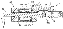
- the stroke sensor 1 is a stroke sensor that detects the movement amount S of the detection shaft 10 that moves from the origin position O following the detected object, and includes the large diameter portion 11, the first washer 18a, and the second washer 18b.
- the first housing 20 having the first receiving portion 21, the second housing 30 having the second receiving portion 31, and the detection shaft 10 after being moved from the home position O
- the spring 40 for returning to the position O, the magnet 51 for changing the magnetic field with the movement of the detection shaft 10, and the magnetic detection for detecting the movement amount S of the detection shaft 10 from the change of the magnetic field with the movement of the detection shaft 10
- an element 52 for detecting the movement amount S of the detection shaft 10 from the change of the magnetic field with the movement of the detection shaft 10
- FIG. 3A shows a cross-sectional view of the detection shaft 10 of the embodiment of the stroke sensor 1.
- the detection shaft 10 is a detection medium to be followed by the movement of the detection object, and for example, the detection shaft 10 is connected to the detection object to transmit an external force, and reciprocates in the axial direction to follow.
- the detection shaft 10 is preferably a nonmagnetic material having a certain degree of rigidity, and is made of, for example, an austenitic stainless steel (Stain Use Stainless; SUS).
- the detection shaft 10 has a large diameter portion 11, a middle diameter portion 12 and a small diameter portion 13 having different cylindrical diameters, and in the present embodiment, the middle diameter portion 12 a and the large diameter portion 11 from the direction of the first housing 20.
- the middle diameter portion 12 b and the small diameter portion 13 are arranged.
- the large diameter portion 11 is disposed in the first housing 20 and supports the first washer 18a.
- the middle diameter portion 12a is disposed in the first housing 20, and is formed with a notched surface 16 in which the side surface of the detection shaft 10 is flatly cut and an end surface 17 in which the cross section of the side surface is substantially D-shaped. Furthermore, the middle diameter portion 12 a has a magnet storage portion 19 for storing the magnet 51.
- the radially inner portion 12b passes the first washer 18a, the spring 40 and the second washer 18b to the large diameter portion 11 side, and the snap ring 14 and the airtight member 15 are attached to the small diameter portion 13 side.
- the small diameter portion 13 protrudes outward from the shaft hole 33 of the second housing 30, and is connected to a detection target (not shown).
- the retaining ring 14 is a radial attachment type retaining ring made of a nonmagnetic material, and is held by a groove (not shown) provided in the middle diameter portion 12b.
- the retaining ring 14 supports the second washer 18b.
- the airtight member 15 is an O-ring made of rubber and is held by a groove provided in the middle diameter portion 12b.
- the airtight member 15 is used to keep the stroke sensor 1 airtight, and the groove is configured to satisfy a groove structure necessary to perform the airtight function of the airtight member 15.
- the notch surface 16 is a flat surface formed by the notch of the side surface of the detection shaft 10 and has an axial length shorter than the axial support portion 22 of the first housing 20.
- the rotation of the detection shaft 10 is regulated by the notched surface 16 in cooperation with a flat portion 22 a of the shaft support 22 described later.
- the end surface 17 is a cross section formed by a notch in the side surface of the detection shaft 10, and has a substantially D shape.
- the height from the notched surface 16 to the apex of the end surface 17 is substantially the same as the digged height of the recess 25 described later.
- the first washer 18a is an O-type washer made of nonmagnetic material, and its diameter is larger than the large diameter portion 11, the inner diameter of the second housing 30, and the spring 40, and the first housing 20 described later It is smaller than the inner diameter of the cylindrical portion 20a.
- the second washer 18 b is an O-type washer made of nonmagnetic material, and its diameter is larger than the hole 32 of the second housing 30 and the spring 40 described later and smaller than the inner diameter of the second housing 30. Configured The first washer 18 a and the second washer 18 b are designed to withstand the thrust load when contacting another member by the movement of the detection shaft 10.
- the magnet storage portion 19 is formed, for example, by boring the inside of the detection shaft 10, stores the magnet 51, and fixes and holds the magnet 51 with an adhesive or the like.
- FIG. 3 b shows a cross-sectional view of the first housing 20 of the embodiment of the stroke sensor 1.
- the first housing 20 includes a first receiving portion 21 for receiving the large-diameter portion 11 of the detection shaft 10, a shaft support portion 22, a first washer support portion 23, an attachment portion 24, a recess 25, and a female screw. It has the part 29 and is comprised.
- the first housing 20 is preferably made of a nonmagnetic material such as aluminum or stainless steel, and is formed of a substantially cylindrical cylindrical portion 20a and a flat plate portion 20b.
- the first receiving portion 21 is an annular surface provided inside the cylindrical portion 20 a, contacts the large diameter portion 11 of the detection shaft 10, and limits the movement amount S of the detection shaft 10.
- the length from the origin position O to the first receiving portion 21 is configured to be smaller than the maximum deflection amount of the spring 40.
- the shaft support portion 22 is provided inside the flat plate portion 20 b and is formed as a groove for supporting the middle diameter portion 12 a of the detection shaft 10.
- the shaft support portion 22 has a flat portion 22 a facing the cutout surface 16 of the detection shaft 10. The rotation around the central axis is restricted by the flat portion 22a and the notch surface 16 of the detection shaft 10, and in addition, it is supported so that the sliding for the detection stroke S is performed with high accuracy in the axial direction.
- the first washer support portion 23 is an annular surface provided inside the cylindrical portion 20a, and the diameter thereof is larger than the large diameter portion 11 of the detection shaft 10 and smaller than the first washer 18a.
- the attachment portion 24 is provided on the outside of the flat plate portion 20b, and is provided with a screw hole for attaching a third housing 60 described later.
- the recess 25 is formed by digging the surface of the mounting portion 24, and is used to place a magnetic detection element 52 described later close to the detection shaft 10.
- the housing is displaced inward by the dug height of the recess 25, and the flat portion 22 a is formed on the shaft support 22.
- the drilled height of the recess 25 substantially coincides with the height from the notch surface 16 of the detection shaft 10 to the apex of the end surface 17.
- the thickness of the housing of the recess 25 is the height from the flat portion 22 a to the recess 25. It is preferable that the thickness of the housing of the recess 25 be substantially the same as the thickness of the housing on the opposite side across the detection shaft 10, that is, the position of line symmetry on the detection shaft 10 axis.
- the internal thread portion 29 is provided on the inner diameter surface of the cylindrical portion 20 a and is used to connect the first housing 20 and the second housing 30.
- FIG. 3 (c) shows a cross-sectional view of the second housing 30 of the embodiment of the stroke sensor 1.
- the second housing 30 is provided with a second receiving portion 31 for receiving the first washer 18 a of the detection shaft 10, a hole 32, a shaft hole 33, a second washer supporting portion 34, and a chamfered portion 35. It has an external thread 39 and is constituted.
- the second housing 30 is preferably formed of a nonmagnetic material such as aluminum or stainless steel and has a substantially cylindrical shape.
- the second receiving portion 31 is an annular surface provided at the edge of the second housing 30, receives the first washer 18a of the detection shaft 10, and limits the movement amount S of the detection shaft 10.
- the length from the origin position O to the second receiving portion 31 is configured to be smaller than the maximum deflection amount of the spring 40.
- the hole 32 is provided inside the second housing 30 in the opposite direction to the second receiving portion 31 and the diameter thereof is larger than that of the retaining ring 14 and smaller than that of the second washer 18b.
- the depth of the hole 32 is set to be slightly longer than the movement amount S so that the retaining ring 14 does not contact the second housing 30 in the thrust direction.
- the shaft hole 33 is provided in the hole 32 and slidably supports the detection shaft 10 and takes it out.
- the second washer support portion 34 is an annular surface provided on the outer periphery of the hole 32, and the diameter thereof is larger than that of the hole 32 and smaller than that of the second washer 18b.
- the chamfered portion 35 is provided in the direction of the hole 32 of the shaft hole 33, and cuts the corner of the shaft hole 33 and makes it smooth.
- the chamfered portion 35 prevents the airtight member 15 from being damaged by the corner portion of the shaft hole 33 when passing the detection shaft 10 from the direction of the hole portion 32 into the shaft hole 33.
- the chamfered portion 35 is positioned in the direction of the large diameter portion 11 of the detection shaft 10 after the detection shaft 10 is passed through the shaft hole 33.
- the male screw 39 is provided on the outer diameter surface of the second housing 30 in the direction opposite to the hole 32 and is used to connect the first housing 20 and the second housing 30. At the time of the connection, the screw may be further prevented from loosening with a reinforcing adhesive (for example, a sealock agent) or the like.
- a reinforcing adhesive for example, a sealock agent
- the spring 40 is preferably made of a nonmagnetic material such as stainless steel, and is formed of, for example, a cylindrical coiled spring made of SUS304WPB.
- the spring 40 is configured to pass the detection shaft 10 inside, and is in contact with the first washer 18 a and the second washer 18 b of the detection shaft 10.
- the spring 40 moves so that the detection shaft 10 at the home position O is pushed in the direction of the first housing 20
- the second washer 18b supported by the retaining ring 14 pushes the spring 40
- the first washer 18a supported by the first washer support 23 supports the spring 40 to crush the spring 40
- the large diameter portion 11 of the detection shaft 10 is the first receiving portion of the first housing 20. It is possible to move by an amount S of movement until it reaches 21. Then, when the force for pushing the detection shaft 10 disappears, the spring force accumulated in the spring 40 returns it to the home position O.
- the spring 40 moves so that the detection shaft 10 at the home position O is drawn toward the second housing 30, the first washer 18a supported by the large diameter portion 11 pushes the spring 40, and The second washer 18b supported by the second washer support 34 supports the spring 40, whereby the spring 40 is crushed and the first washer 18a supported by the large diameter portion 11 of the detection shaft 10 Can move by an amount S of movement until it strikes the second receiving portion 31 of the second housing 30. Then, when the force for pulling in the detection shaft 10 disappears, the spring force accumulated in the spring 40 causes the detection shaft 10 to return to the home position O.
- the magnet 51 is formed of a cylindrical rare earth-based magnet (for example, a magnet of a material such as SmCo or NdFeB), and is attached to the magnet housing portion 19 of the detection shaft 10.
- a cylindrical rare earth-based magnet for example, a magnet of a material such as SmCo or NdFeB
- the magnet 51 provides a magnetic field to the magnetic detection element 52, and movement of the magnet 51 with the detection shaft 10 changes the direction and strength of the magnetic field applied to the magnetic detection element 52, and consequently the magnetic detection element 52. Detects as the movement amount S.
- the magnet 51 may be any of a sintered magnet and a plastic magnet mixed or compressed with a plastic by a manufacturing method.
- the sintered magnet has a stronger magnetic force, while the plastic magnet has characteristics such as high mass productivity and high crack resistance. Therefore, it may be appropriately selected according to the use conditions and design requirements.
- the magnetic detection element 52 detects a change such as the amount of movement of the object to be detected by the direction and strength of the magnetic field, and is formed of, for example, a Hall element, and the change of the magnetic field accompanying the movement of the object Is converted to an electrical signal and output to the outside.
- the detection of the movement amount S of the detection shaft 10 by the magnetic detection element 52 detects changes in the direction and strength of the magnetic field emitted by the magnet 51 provided on the detection shaft 10, and converts it into an electrical signal corresponding to the magnetic field. Output to the outside.
- the substrate 50 is a printed circuit board (PCB) made of glass epoxy or the like, and includes a magnetic detection element 52.
- PCB printed circuit board
- the power supply to the magnetic detection element 52 of the substrate 50 and the output of the electric signal to the outside are performed by a direct connector or a cord.
- the third housing 60 is made of a resin material such as epoxy resin, and is coupled to the mounting portion 24 of the first housing 20 by screws.
- the third housing 60 includes a substrate storage portion 61 and an outlet 62.
- the substrate storage unit 61 is configured to hold the substrate 50 in the third housing 60 and to place the magnetic detection element 52 close to the recess 25 of the first housing 20.
- the extraction port 62 extracts the direct connector or cord of the substrate 50 to the outside.
- the large diameter portion 11 is received by the first receiving portion 21 of the first housing 20, and the first washer 18a is received by the second receiving portion 31 of the second housing 30, so that the detection shaft is not added.
- the movement amount S of 10 can be limited. According to this, the assembly process can be simplified and the material cost can be reduced.
- the amount of crushing of the spring 40 is reduced. According to this, the load on the spring 40 can be reduced and the life can be extended.
- the diameter of the large diameter portion 11 can be reduced by using the first washer 18 a having a diameter larger than that of the large diameter portion 11 of the detection shaft 10. According to this, the diameter of the detection shaft material before cutting can be reduced, and the material cost and the processing cost can be reduced.
- the airtight member 15 can be prevented from being damaged by the corner portion of the shaft hole 33 when the stroke sensor 1 is assembled. According to this, the assembly accuracy can be improved and the defective product rate can be reduced.
- first housing 20 and the second housing 30 are made of nonmagnetic material, one or both of the first housing 20 and the second housing 30 are made of resin. You may
Landscapes
- Physics & Mathematics (AREA)
- General Physics & Mathematics (AREA)
- Measurement Of Length, Angles, Or The Like Using Electric Or Magnetic Means (AREA)
- Transmission And Conversion Of Sensor Element Output (AREA)
Abstract
構造を簡素化してコストを低減したストロークセンサを提供する。 被検出体に追従して原点位置Oから移動する検出シャフト10の移動量Sを検出するストロークセンサであって、径大部11と第一の座金18aと第二の座金18bを有する検出シャフト10と、第一の受部21を有する第一のハウジング20と、第二の受部31を有する第二のハウジング30と、原点位置Oから移動した後の検出シャフト10を原点位置Oに復帰させるスプリング40と、検出シャフト10の移動に伴って磁界を変化させるための磁石51と、検出シャフト10の移動に伴う磁界の変化から検出シャフト10の移動量Sを検出する磁気検出素子52と、を備え、第一の受部21が径大部11を受け、第二の受部32が第一の座金18aを受けることにより検出シャフト10の移動量Sを制限する。
Description
本発明はストロークセンサに関する。
自動車や自動2輪車のレバーなどの移動体の移動量を検出するストロークセンサとして、例えば、特許文献1に開示されたものがある。
このストロークセンサは、被検出体の移動に追従し設けた検出シャフトと、検出シャフトの回転を規制して摺動可能に支持するハウジングと、検出シャフトとハウジングとの間に設けられ移動量を検出して移動した後の検出シャフトを原点位置に復帰させる原点復帰機構と、を備え、検出シャフトに設けられた磁石とハウジングに設けられた磁気検出素子により被検出体が軸方向に往復する移動量を磁界の変化によって検出するものである。
このストロークセンサは、被検出体の移動に追従し設けた検出シャフトと、検出シャフトの回転を規制して摺動可能に支持するハウジングと、検出シャフトとハウジングとの間に設けられ移動量を検出して移動した後の検出シャフトを原点位置に復帰させる原点復帰機構と、を備え、検出シャフトに設けられた磁石とハウジングに設けられた磁気検出素子により被検出体が軸方向に往復する移動量を磁界の変化によって検出するものである。
しかしながら、特許文献1記載のストロークセンサは、検出シャフトの移動量の制限に2つのピストンを用いた原点復帰機構を備えるため、構造が複雑になり、部品点数が増えるという問題がある。
本発明は、上記問題点に鑑みてなされたものであり、構造を簡素化してコストを低減したストロークセンサを提供することを目的とする。
上記目的を達成するため、本発明に係るストロークセンサは、
被検出体に追従して原点位置から移動する検出シャフトの移動量を検出するストロークセンサであって、
径大部と第一の座金と第二の座金を有する前記検出シャフトと、
前記検出シャフトを支持する第一のハウジングと、
前記検出シャフトを支持する第二のハウジングと、
前記原点位置から移動した後の前記検出シャフトを前記原点位置に復帰させるスプリングと、
前記検出シャフトの移動に伴って磁界を変化させるための磁石と、
前記検出シャフトの移動に伴う磁界の変化から前記検出シャフトの前記移動量を検出する磁気検出素子と、
を備え、
前記第一のハウジングは、前記径大部を受ける第一の受部を有し、
前記第二のハウジングは、前記第一の座金を受ける第二の受部を有し、
前記第一の座金、及び前記第二の座金は、前記スプリングと接し、
前記第一の受部と前記第二の受部は、前記検出シャフトの前記移動量を制限する、
ことを特徴とする。
被検出体に追従して原点位置から移動する検出シャフトの移動量を検出するストロークセンサであって、
径大部と第一の座金と第二の座金を有する前記検出シャフトと、
前記検出シャフトを支持する第一のハウジングと、
前記検出シャフトを支持する第二のハウジングと、
前記原点位置から移動した後の前記検出シャフトを前記原点位置に復帰させるスプリングと、
前記検出シャフトの移動に伴って磁界を変化させるための磁石と、
前記検出シャフトの移動に伴う磁界の変化から前記検出シャフトの前記移動量を検出する磁気検出素子と、
を備え、
前記第一のハウジングは、前記径大部を受ける第一の受部を有し、
前記第二のハウジングは、前記第一の座金を受ける第二の受部を有し、
前記第一の座金、及び前記第二の座金は、前記スプリングと接し、
前記第一の受部と前記第二の受部は、前記検出シャフトの前記移動量を制限する、
ことを特徴とする。
本発明によれば、構造を簡素化してコストを低減したストロークセンサを提供することができる。
以下に、本発明に係るストロークセンサを添付図面に基づいて説明する。
図1、及び図2を参照する。図1は、ストロークセンサ1の実施例の平面図を示す。図2は、ストロークセンサ1の実施例の断面図を示す。ストロークセンサ1は、被検出体に追従して原点位置Oから移動する検出シャフト10の移動量Sを検出するストロークセンサであって、径大部11と第一の座金18aと第二の座金18bを有する検出シャフト10と、第一の受部21を有する第一のハウジング20と、第二の受部31を有する第二のハウジング30と、原点位置Oから移動した後の検出シャフト10を原点位置Oに復帰させるスプリング40と、検出シャフト10の移動に伴って磁界を変化させるための磁石51と、検出シャフト10の移動に伴う磁界の変化から検出シャフト10の移動量Sを検出する磁気検出素子52と、を備える。
図3(a)を併せて参照する。図3(a)は、ストロークセンサ1の実施例の検出シャフト10の断面図を示す。検出シャフト10は、被検出体の移動によって追従される検出媒体であり、例えば、被検出体に連結されて外力が伝達され、軸方向に往復して追従する。検出シャフト10は、ある程度剛性を有する非磁性材料が好ましく、例えばオーステナイト系のステンレス鋼(Steel Use Stainless; SUS)からなる。
検出シャフト10は、円柱状の直径の異なる径大部11、径中部12、及び径小部13を有し、本実施例では、第一のハウジング20の方向から径中部12a、径大部11、径中部12b、径小部13の並びで構成される。
径大部11は、第一のハウジング20内に配置され、第一の座金18aを支持する。
径中部12aは、第一のハウジング20内に配置され、検出シャフト10の側面を平坦に切り欠いた切り欠き面16と前記側面の横断面が略D形状である端面17が形成される。さらに、径中部12aは、磁石51を収納する磁石収納部19を有している。
径中部12bは、径大部11側に第一の座金18a、スプリング40、第二の座金18bを通し、径小部13側に止め輪14と気密部材15が取り付けられる。
径小部13は、第二のハウジング30のシャフト穴33から外側に突き出しており、図示しない被検出体と接続される。
止め輪14は、非磁性材料からなるラジアル方向取り付け式止め輪であり、径中部12bに設けられた図示しない溝によって保持される。止め輪14は、第二の座金18bを支持する。
気密部材15は、ゴムからなるOリングであり、径中部12bに設けられた溝によって保持される。気密部材15は、ストロークセンサ1の気密を保つために用いられ、前記溝は、気密部材15の気密機能を発揮するために必要な溝構造を満たすように構成される。
切り欠き面16は、検出シャフト10の側面の切り欠きにより形成された平坦な面であり、第一のハウジング20の軸支持部22よりも短い軸方向の長さを有している。この切り欠き面16によって検出シャフト10の回転が、後述する軸支持部22の平面部22aと協働して、規制される。
端面17は、検出シャフト10の側面の切り欠きにより形成された横断面であり、略D形状を有する。切り欠き面16から端面17の頂点までの高さは、後述する凹部25の掘り下げた高さと略一致する。
第一の座金18aは、非磁性材料からなるO型のワッシャであり、その直径は径大部11、第二のハウジング30の内径、及びスプリング40よりも大きく、後述する第一のハウジング20の円筒部20aの内径よりも小さく構成される。
第二の座金18bは、非磁性材料からなるO型のワッシャであり、その直径は後述する第二のハウジング30の孔部32、及びスプリング40よりも大きく、第二のハウジング30の内径より小さく構成される。
第一の座金18a、及び第二の座金18bは、検出シャフト10の移動により、別の部材に接触した際のスラスト荷重に耐えるように設計される。
第二の座金18bは、非磁性材料からなるO型のワッシャであり、その直径は後述する第二のハウジング30の孔部32、及びスプリング40よりも大きく、第二のハウジング30の内径より小さく構成される。
第一の座金18a、及び第二の座金18bは、検出シャフト10の移動により、別の部材に接触した際のスラスト荷重に耐えるように設計される。
磁石収納部19は、例えば検出シャフト10の内部をくりぬいて形成され、磁石51を収納し接着剤などで固定して保持する。
図3(b)を併せて参照する。図3(b)は、ストロークセンサ1の実施例の第一のハウジング20の断面図を示す。第一のハウジング20は、検出シャフト10の径大部11を受ける第一の受部21と、軸支持部22と、第一の座金支持部23と、取り付け部24と、凹部25と、雌ねじ部29を有して構成される。
第一のハウジング20は、アルミニウムやステンレス鋼などの非磁性材料が好ましく、略円筒状の円筒部20aと平板状の平板部20bによって形成されている。
第一の受部21は、円筒部20aの内側に設けられる円環状の面であり、検出シャフト10の径大部11と接し、検出シャフト10の移動量Sを制限する。原点位置Oから第一の受部21までの長さは、スプリング40の最大たわみ量より小さくなるように構成される。
軸支持部22は、平板部20bの内側に設けられ、検出シャフト10の径中部12aを支持する溝として形成される。軸支持部22は、検出シャフト10の切り欠き面16に対向する平面部22aを有する。平面部22aと検出シャフト10の切り欠き面16によって、中心軸回りの回転が規制され、しかも軸方向には、検出ストロークS分の摺動が高精度になされるように支持される。
第一の座金支持部23は、円筒部20aの内側に設けられる円環状の面であり、その直径は検出シャフト10の径大部11より大きく、第一の座金18aよりも小さい。
取り付け部24は、平板部20bの外側に設けられ、後述する第三のハウジング60を取り付けるためのねじ穴が設けられる。
凹部25は、取り付け部24の表面を掘り下げて構成されており、後述する磁気検出素子52を検出シャフト10に近づけて配置するために用いられる。凹部25の前記掘り下げられた高さの分だけ内側にハウジングが変位し、軸支持部22に平面部22aが形成される。凹部25の前記掘り下げられた高さは、検出シャフト10の切り欠き面16から端面17の頂点までの高さと略一致する。
凹部25のハウジングの厚みは、平面部22aから凹部25までの高さとなる。凹部25のハウジングの厚みは、検出シャフト10を挟んだ反対側、すなわち検出シャフト10を軸とした線対称の位置にあるハウジングの厚みと略一致することが好ましい。
凹部25のハウジングの厚みは、平面部22aから凹部25までの高さとなる。凹部25のハウジングの厚みは、検出シャフト10を挟んだ反対側、すなわち検出シャフト10を軸とした線対称の位置にあるハウジングの厚みと略一致することが好ましい。
雌ねじ部29は、円筒部20aの内径面に備えられ、第一のハウジング20と第二のハウジング30を連結するために用いられる。
図3(c)を併せて参照する。図3(c)は、ストロークセンサ1の実施例の第二のハウジング30の断面図を示す。第二のハウジング30は、検出シャフト10の第一の座金18aを受ける第二の受部31と、孔部32と、シャフト穴33と、第二の座金支持部34と、面取り部35と、雄ねじ部39を有して構成される。
第二のハウジング30は、アルミニウムやステンレス鋼などの非磁性材料が好ましく、略円筒状に形成されている。
第二の受部31は、第二のハウジング30の縁に設けられる円環状の面であり、検出シャフト10の第一の座金18aを受け、検出シャフト10の移動量Sを制限する。原点位置Oから第二の受部31までの長さは、スプリング40の最大たわみ量より小さくなるように構成される。
孔部32は、第二の受部31と反対方向の第二のハウジング30の内側に設けられ、その直径は止め輪14よりも大きく、第二の座金18bよりも小さく構成される。孔部32の深さは、移動量Sより少し長く設けられ、止め輪14が第二のハウジング30とスラスト方向に接しないように構成されている。
シャフト穴33は、孔部32に設けられ、検出シャフト10を摺動可能に支持して外部に取り出す。
第二の座金支持部34は、孔部32の外周に設けられる円環状の面であり、その直径は孔部32より大きく、第二の座金18bよりも小さく構成される。
面取り部35は、シャフト穴33の孔部32の方向に設けられ、シャフト穴33の角部を削り滑らかにしている。面取り部35は、検出シャフト10を孔部32の方向からシャフト穴33に通す際に、気密部材15がシャフト穴33の角部により傷つくことを防止する。面取り部35は、検出シャフト10をシャフト穴33に通した後に、検出シャフト10の径大部11の方向に位置する。
雄ねじ部39は、孔部32と反対方向の第二のハウジング30の外径面に備えられ、第一のハウジング20と第二のハウジング30を連結するために用いられる。前記連結に際しては、補強用接着剤(例えば、シーロック剤)などでねじの緩み防止をさらに行ってもよい。
スプリング40は、ステンレス鋼などの非磁性材料のものが好ましく、例えばSUS304WPBによる円筒状のコイルばねで構成される。
スプリング40は、内側に検出シャフト10を通すように構成され、検出シャフト10の第一の座金18a、及び第二の座金18bと接している。
スプリング40は、原点位置Oにある検出シャフト10が第一のハウジング20の方向に押し込まれるように移動すると、止め輪14に支持された第二の座金18bがスプリング40を押し、且つ、第一の座金支持部23に支持された第一の座金18aがスプリング40を支持することで、スプリング40が押し潰され、検出シャフト10の径大部11が第一のハウジング20の第一の受部21に当たるまでの移動量S分だけ移動することができる。そして、検出シャフト10を押し込む力がなくなると、スプリング40に蓄積されたばね力で、原点位置Oに戻される。
また、スプリング40は、原点位置Oにある検出シャフト10が第二のハウジング30の方向に引き込まれるように移動すると、径大部11に支持された第一の座金18aがスプリング40を押し、且つ、第二の座金支持部34に支持された第二の座金18bがスプリング40を支持することで、スプリング40が押し潰され、検出シャフト10の径大部11によって支持された第一の座金18aが第二のハウジング30の第二の受部31に当たるまでの移動量S分だけ移動することができる。そして、検出シャフト10を引き込む力がなくなると、スプリング40に蓄積されたばね力で、原点位置Oに戻される。
磁石51は、円柱状に形成された希土類系磁石(例えば、SmCoやNdFeBなどの材料の磁石)からなり、検出シャフト10の磁石収納部19に取り付けられる。
磁石51は、磁気検出素子52に磁界を提供しており、磁石51が検出シャフト10とともに移動することで磁気検出素子52へ与える磁界の向き、及び強さを変え、結果的に磁気検出素子52が移動量Sとして検出する。磁石51は、製造手法により焼結磁石やプラスチックと混ぜて圧縮もしくは成形されたプラスチック磁石などのいずれでもよい。焼結磁石の方が強力な磁力を有する一方、プラスチック磁石の方が大量生産性や耐割れ性が高いなど特性があることから、使用条件や設計要件に応じて適宜選択すればよい。
磁気検出素子52は、被検出体の移動量などの変化を磁界の向き、及び強さにより検出するものであり、例えば、ホール素子などで構成され、被検出体の移動などに伴う磁界の変化を電気信号に変換して外部に出力するものである。
磁気検出素子52による検出シャフト10の移動量Sの検出は、検出シャフト10に備えられた磁石51が発する磁界の向き、及び強さの変化を検出し、前記磁界に応じた電気信号に変換して外部に出力する。
基板50は、ガラスエポキシ等からなるプリント基板(Printed Circuit Board; PCB)であり、磁気検出素子52を備える。
基板50の磁気検出素子52への電源の取り込みや外部への電気信号の出力は、ダイレクトコネクタもしくはコードにて行われる。
第三のハウジング60は、エポキシ樹脂等の樹脂材料からなり、第一のハウジング20の取り付け部24とねじによって結合される。
第三のハウジング60は、基板収納部61と、引き出し口62を備える。
基板収納部61は、第三のハウジング60に基板50を保持し、磁気検出素子52を第一のハウジング20の凹部25に近づけて配置するように構成される。
引き出し口62は、基板50のダイレクトコネクタもしくはコードを外部へ引き出す。
以上に説明した本発明は、以下の効果を奏する。
第一のハウジング20の第一の受部21で径大部11を、第二のハウジング30の第二の受部31で第一の座金18aを受けることで、部材の追加なしで、検出シャフト10の移動量Sを制限できる。これによれば、組み立て工程を簡略化し、材料費を低減できる。
検出シャフト10の移動量Sを制限することで、スプリング40の押し潰される量が小さくなる。これによれば、スプリング40の負担を軽減し、長寿命化できる。
検出シャフト10の径大部11よりも直径の大きい第一の座金18aを用いることで、径大部11の直径を小さくすることができる。これによれば、切削加工前の検出シャフト材料の直径を小さくすることができ、材料費、及び加工費を低減できる。
第二のハウジング30のシャフト穴33に面取り部35を設けることで、ストロークセンサ1の組み立て時に気密部材15がシャフト穴33の角部により傷つくことを防止することができる。これによれば、組み立て精度を向上し、不良品率を低減できる。
なお、上記の実施例において、第一のハウジング20、及び第二のハウジング30を非磁性材料で構成したが、第一のハウジング20、及び第二のハウジング30の片方、あるいは両方を樹脂で構成してもよい。
本発明は、以上の実施例及び図面によって限定されるものではない。本発明の要旨を変更しない範囲で、適宜、変更(構成要素の削除も含む)を加えることが可能である。
1 ストロークセンサ
10 検出シャフト
11 径大部
12 径中部
13 径小部
14 止め輪
15 気密部材
18a 第一の座金
18b 第二の座金
20 第一のハウジング
20a 円筒部
20b 平板部
21 第一の受部
22 軸支持部
23 第一の座金支持部
30 第二のハウジング
31 第二の受部
32 孔部
33 シャフト穴
34 第二の座金支持部
35 面取り部
40 スプリング
50 基板
51 磁石
52 磁気検出素子
60 第三のハウジング
O 原点位置
S 移動量
10 検出シャフト
11 径大部
12 径中部
13 径小部
14 止め輪
15 気密部材
18a 第一の座金
18b 第二の座金
20 第一のハウジング
20a 円筒部
20b 平板部
21 第一の受部
22 軸支持部
23 第一の座金支持部
30 第二のハウジング
31 第二の受部
32 孔部
33 シャフト穴
34 第二の座金支持部
35 面取り部
40 スプリング
50 基板
51 磁石
52 磁気検出素子
60 第三のハウジング
O 原点位置
S 移動量
Claims (5)
- 被検出体に追従して原点位置から移動する検出シャフトの移動量を検出するストロークセンサであって、
径大部と第一の座金と第二の座金を有する前記検出シャフトと、
前記検出シャフトを支持する第一のハウジングと、
前記検出シャフトを支持する第二のハウジングと、
前記原点位置から移動した後の前記検出シャフトを前記原点位置に復帰させるスプリングと、
前記検出シャフトの移動に伴って磁界を変化させるための磁石と、
前記検出シャフトの移動に伴う磁界の変化から前記検出シャフトの前記移動量を検出する磁気検出素子と、
を備え、
前記第一のハウジングは、前記径大部を受ける第一の受部を有し、
前記第二のハウジングは、前記第一の座金を受ける第二の受部を有し、
前記第一の座金、及び前記第二の座金は、前記スプリングと接し、
前記第一の受部と前記第二の受部は、前記検出シャフトの前記移動量を制限する、
ことを特徴とするストロークセンサ。 - 前記検出シャフトは、止め輪をさらに有し、
前記第一のハウジングは、第一の座金支持部をさらに有し、
前記検出シャフトが前記第一のハウジングの方向に移動する場合に、前記止め輪に支持された前記第二の座金が前記スプリングを押し、且つ、前記第一の座金支持部に支持された前記第一の座金が前記スプリングを支持する、
ことを特徴とする請求項1に記載のストロークセンサ。 - 前記第二のハウジングは、第二の座金支持部をさらに有し、
前記検出シャフトが前記第二のハウジングの方向に移動する場合に、前記径大部に支持された前記第一の座金が前記スプリングを押し、且つ、前記第二の座金支持部に支持された前記第二の座金が前記スプリングを支持する、
ことを特徴とする請求項1乃至2のいずれか1つに記載のストロークセンサ。 - 前記第二のハウジングは、前記検出シャフトを通すシャフト穴をさらに備え、
前記シャフト穴は、前記検出シャフトの前記径大部の方向に前記シャフト穴の角部を面取りした面取り部を有する、
ことを特徴とする請求項1乃至3のいずれか1つに記載のストロークセンサ。 - 前記ストロークセンサは、第三のハウジングをさらに備え、
前記検出シャフトは、前記磁石を有し、
前記第三のハウジングは、前記磁気検出素子を有した基板を収納する収納部を備える、
ことを特徴とする請求項1乃至4のいずれか1つに記載のストロークセンサ。
Priority Applications (2)
| Application Number | Priority Date | Filing Date | Title |
|---|---|---|---|
| CN201880076355.5A CN111386438B (zh) | 2017-11-30 | 2018-11-26 | 行程传感器 |
| JP2019557207A JP7126087B2 (ja) | 2017-11-30 | 2018-11-26 | ストロークセンサ |
Applications Claiming Priority (2)
| Application Number | Priority Date | Filing Date | Title |
|---|---|---|---|
| JP2017229744 | 2017-11-30 | ||
| JP2017-229744 | 2017-11-30 |
Publications (1)
| Publication Number | Publication Date |
|---|---|
| WO2019107293A1 true WO2019107293A1 (ja) | 2019-06-06 |
Family
ID=66664060
Family Applications (1)
| Application Number | Title | Priority Date | Filing Date |
|---|---|---|---|
| PCT/JP2018/043316 Ceased WO2019107293A1 (ja) | 2017-11-30 | 2018-11-26 | ストロークセンサ |
Country Status (3)
| Country | Link |
|---|---|
| JP (1) | JP7126087B2 (ja) |
| CN (1) | CN111386438B (ja) |
| WO (1) | WO2019107293A1 (ja) |
Citations (4)
| Publication number | Priority date | Publication date | Assignee | Title |
|---|---|---|---|---|
| JPS4880562U (ja) * | 1971-12-28 | 1973-10-02 | ||
| JP2011158027A (ja) * | 2010-02-01 | 2011-08-18 | Santest Co Ltd | 位置と負荷の検出可能な流体圧アクチュエータ |
| WO2016057375A1 (en) * | 2014-10-06 | 2016-04-14 | Apex Brands, Inc. | Electronic counter for fluid flow tools |
| JP2017015549A (ja) * | 2015-06-30 | 2017-01-19 | 日本精機株式会社 | ストロークセンサ |
Family Cites Families (9)
| Publication number | Priority date | Publication date | Assignee | Title |
|---|---|---|---|---|
| SE512576C2 (sv) * | 1997-08-25 | 2000-04-03 | Volvo Penta Ab | Anordning för assisterad växling vid transmission |
| AUPQ074299A0 (en) * | 1999-06-03 | 1999-06-24 | Shelljet Pty Limited | Core orientation |
| CN100376872C (zh) * | 2006-03-28 | 2008-03-26 | 王允学 | 隔离式线性位移变送装置 |
| JP4880562B2 (ja) * | 2007-10-05 | 2012-02-22 | 日本特殊陶業株式会社 | エンジン用圧力センサ |
| CN201653409U (zh) * | 2010-04-22 | 2010-11-24 | 浙江金华托派特工具有限公司 | 一种数显角度水平尺 |
| CN202083342U (zh) * | 2011-05-26 | 2011-12-21 | 杭州富如德科技有限公司 | 一种检测钢带输送跑偏量的位移传感器 |
| CN204924122U (zh) * | 2015-05-05 | 2015-12-30 | 贵州航天工业学校 | 一种轴类零件检测装置 |
| CN105953717B (zh) * | 2016-06-30 | 2019-02-01 | 深圳市信为科技发展有限公司 | 气动式位移传感器结构 |
| CN206487558U (zh) * | 2016-11-15 | 2017-09-12 | 广州杰治文电子科技有限公司 | 一种摩托车用基于步进电机的电子节气门控制系统 |
-
2018
- 2018-11-26 CN CN201880076355.5A patent/CN111386438B/zh active Active
- 2018-11-26 WO PCT/JP2018/043316 patent/WO2019107293A1/ja not_active Ceased
- 2018-11-26 JP JP2019557207A patent/JP7126087B2/ja active Active
Patent Citations (4)
| Publication number | Priority date | Publication date | Assignee | Title |
|---|---|---|---|---|
| JPS4880562U (ja) * | 1971-12-28 | 1973-10-02 | ||
| JP2011158027A (ja) * | 2010-02-01 | 2011-08-18 | Santest Co Ltd | 位置と負荷の検出可能な流体圧アクチュエータ |
| WO2016057375A1 (en) * | 2014-10-06 | 2016-04-14 | Apex Brands, Inc. | Electronic counter for fluid flow tools |
| JP2017015549A (ja) * | 2015-06-30 | 2017-01-19 | 日本精機株式会社 | ストロークセンサ |
Also Published As
| Publication number | Publication date |
|---|---|
| CN111386438A (zh) | 2020-07-07 |
| JPWO2019107293A1 (ja) | 2020-12-03 |
| JP7126087B2 (ja) | 2022-08-26 |
| CN111386438B (zh) | 2022-04-15 |
Similar Documents
| Publication | Publication Date | Title |
|---|---|---|
| US8978509B2 (en) | Robot arm assembly | |
| US20090072816A1 (en) | Rotary Magnetic Encoder Assembly, Chip and Method | |
| KR101940820B1 (ko) | 위치 센서 | |
| US20140259717A1 (en) | Concentricity test device | |
| JP7076063B2 (ja) | ストロークセンサ | |
| JP2019100779A (ja) | ストロークセンサ | |
| JP2014055911A (ja) | 無接触型ポテンショメータ | |
| EP3249264A3 (en) | Shifter location system for a motor vehicle | |
| CN103996487B (zh) | 外衔铁式高精度定位电磁铁 | |
| JP6935728B2 (ja) | ストロークセンサ | |
| US8613432B2 (en) | Positioning fixture | |
| JP7126087B2 (ja) | ストロークセンサ | |
| JP6540285B2 (ja) | ストロークセンサ | |
| CN114242496A (zh) | 一种电子设备、按键装置 | |
| CN219573096U (zh) | 行程传感器 | |
| CN217275992U (zh) | 行程传感器 | |
| JP2017125681A (ja) | ストロークセンサ | |
| JP2015010876A (ja) | ストロークセンサ | |
| JP7711528B2 (ja) | ストロークセンサ | |
| JP6693303B2 (ja) | ストロークセンサ | |
| JP2020071104A (ja) | ストロークセンサ | |
| JP2020139838A (ja) | ストロークセンサ | |
| JP2020139839A (ja) | ストロークセンサ | |
| WO2018003651A1 (ja) | ストロークセンサ | |
| JP2020159861A (ja) | ストロークセンサ |
Legal Events
| Date | Code | Title | Description |
|---|---|---|---|
| 121 | Ep: the epo has been informed by wipo that ep was designated in this application |
Ref document number: 18884377 Country of ref document: EP Kind code of ref document: A1 |
|
| ENP | Entry into the national phase |
Ref document number: 2019557207 Country of ref document: JP Kind code of ref document: A |
|
| NENP | Non-entry into the national phase |
Ref country code: DE |
|
| 122 | Ep: pct application non-entry in european phase |
Ref document number: 18884377 Country of ref document: EP Kind code of ref document: A1 |