WO2019102980A1 - Braided wire and wire harness - Google Patents
Braided wire and wire harness Download PDFInfo
- Publication number
- WO2019102980A1 WO2019102980A1 PCT/JP2018/042758 JP2018042758W WO2019102980A1 WO 2019102980 A1 WO2019102980 A1 WO 2019102980A1 JP 2018042758 W JP2018042758 W JP 2018042758W WO 2019102980 A1 WO2019102980 A1 WO 2019102980A1
- Authority
- WO
- WIPO (PCT)
- Prior art keywords
- wire
- braided
- strand
- harness
- braided wire
- Prior art date
Links
Images


Classifications
-
- B—PERFORMING OPERATIONS; TRANSPORTING
- B60—VEHICLES IN GENERAL
- B60R—VEHICLES, VEHICLE FITTINGS, OR VEHICLE PARTS, NOT OTHERWISE PROVIDED FOR
- B60R16/00—Electric or fluid circuits specially adapted for vehicles and not otherwise provided for; Arrangement of elements of electric or fluid circuits specially adapted for vehicles and not otherwise provided for
- B60R16/02—Electric or fluid circuits specially adapted for vehicles and not otherwise provided for; Arrangement of elements of electric or fluid circuits specially adapted for vehicles and not otherwise provided for electric constitutive elements
-
- H—ELECTRICITY
- H01—ELECTRIC ELEMENTS
- H01B—CABLES; CONDUCTORS; INSULATORS; SELECTION OF MATERIALS FOR THEIR CONDUCTIVE, INSULATING OR DIELECTRIC PROPERTIES
- H01B5/00—Non-insulated conductors or conductive bodies characterised by their form
- H01B5/12—Braided wires or the like
-
- H—ELECTRICITY
- H01—ELECTRIC ELEMENTS
- H01B—CABLES; CONDUCTORS; INSULATORS; SELECTION OF MATERIALS FOR THEIR CONDUCTIVE, INSULATING OR DIELECTRIC PROPERTIES
- H01B7/00—Insulated conductors or cables characterised by their form
-
- H—ELECTRICITY
- H01—ELECTRIC ELEMENTS
- H01B—CABLES; CONDUCTORS; INSULATORS; SELECTION OF MATERIALS FOR THEIR CONDUCTIVE, INSULATING OR DIELECTRIC PROPERTIES
- H01B7/00—Insulated conductors or cables characterised by their form
- H01B7/04—Flexible cables, conductors, or cords, e.g. trailing cables
-
- H—ELECTRICITY
- H01—ELECTRIC ELEMENTS
- H01B—CABLES; CONDUCTORS; INSULATORS; SELECTION OF MATERIALS FOR THEIR CONDUCTIVE, INSULATING OR DIELECTRIC PROPERTIES
- H01B7/00—Insulated conductors or cables characterised by their form
- H01B7/17—Protection against damage caused by external factors, e.g. sheaths or armouring
- H01B7/18—Protection against damage caused by wear, mechanical force or pressure; Sheaths; Armouring
-
- H—ELECTRICITY
- H02—GENERATION; CONVERSION OR DISTRIBUTION OF ELECTRIC POWER
- H02G—INSTALLATION OF ELECTRIC CABLES OR LINES, OR OF COMBINED OPTICAL AND ELECTRIC CABLES OR LINES
- H02G3/00—Installations of electric cables or lines or protective tubing therefor in or on buildings, equivalent structures or vehicles
- H02G3/02—Details
- H02G3/04—Protective tubing or conduits, e.g. cable ladders or cable troughs
Definitions
- the present invention relates to a braided wire and a wire harness.
- a braided wire formed by weaving a plurality of strands into a tubular shape is used in a wire harness used for a vehicle such as an automobile.
- a copper-based wire such as a bare soft copper wire, an oxygen-free soft copper wire, or a tin-plated soft copper wire has been used as a wire forming a braided wire of this type.
- the present invention has been made in view of the above background, and an object of the present invention is to provide a braided wire capable of suppressing the breakage of a strand due to vibration and a wire harness using the same.
- One aspect of the present invention is a tubular braided wire having a plurality of braided strands,
- the wire is made of aluminum wire or aluminum alloy wire,
- the outer shape of the wire is a braided wire having a pair of substantially parallel linear portions when viewed in a cross section perpendicular to the wire axis.
- Another aspect of the present invention is a wire harness having the above-mentioned braided wire.
- the wire constituting the braided wire is composed of an aluminum wire or an aluminum alloy wire, and when viewed in a cross section perpendicular to the wire axis, the wire has a pair of straight portions having a substantially parallel outer shape of the wire. doing.
- the strands are in point contact with each other in the braided portion of the strand, whereas in the braided wire, the strands are in surface contact with each other in the braided portion of the strand. Therefore, according to the said braided wire, the stress by the vibration concerning the contact part of strands can be relieved, and a disconnection of a strand can be controlled.
- the wire harness has the braided wire. Therefore, in the above-mentioned wire harness, even when vibration is loaded, disconnection of the strands of wire in the braided wire is suppressed. So, according to the said wire harness, the shield reliability by a braided wire can be improved.
- FIG. 1 is an external view schematically showing a braided wire of Example 1; It is the figure which showed typically the II-II line cross section in FIG. It is the figure which showed typically the cross section perpendicular
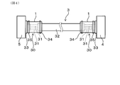
- FIG. It is the figure which showed typically the wire harness of Example 1, and the application example of the said wire harness.
- the wires are made of aluminum wires or aluminum alloy wires.
- an aluminum alloy 1000 series Al alloy, 3000 series Al alloy, 5000 series Al alloy, 6000 series Al alloy, 7000 series Al alloy etc. can be illustrated, for example.
- an aluminum alloy for example, 0.1% to 1.5% of Mg, 0.03% to 2.0% of Si, 0.05% or more of Cu in mass%
- An example is an aluminum alloy having a chemical composition which contains 0.5% or less, the balance is Al and unavoidable impurities, and the mass ratio Mg / Si of Mg and Si is 0.8 or more and 3.5 or less. it can.
- the aluminum alloy having the above-mentioned chemical composition can have a tensile strength of 200 MPa or more and a conductivity of 50% IACS or more.
- the chemical composition may further contain at least one element of Fe: 0.1% to 1.0% and Cr: 0.01% to 0.5% by mass%. it can. Moreover, the said chemical composition can further contain at least 1 element of Ti: 500 ppm or less and B: 50 ppm or less by a mass ratio.
- the plurality of strands constituting the braided wire may be composed of aluminum wires or aluminum alloy wires of the same material, or aluminum wires or aluminum alloy wires of different materials. It is also good.
- the former configuration in the entire braided wire, variations in bending characteristics of the strands are less likely to occur, and the bending characteristics are easily made uniform. Therefore, according to the configuration of the former, even in the case where bending and distortion are repeatedly received, it is difficult to generate a portion which is easily broken locally, and it becomes easy to suppress the breakage of the wire due to the vibration.
- an aluminum wire or an aluminum alloy wire may have a chemical conversion film, an alumite film (anodic oxide film), a rust preventive film, etc. on the surface.
- a chemical conversion film an alumite film (anodic oxide film), a rust preventive film, etc.
- the friction coefficient of the surface of the wire is reduced compared to the bare aluminum-based wire, and the slipperiness of the wires is easily improved, so that the above-described abrasion corrosion due to the vibration is easily suppressed.
- the outer shape of the strand has a pair of substantially parallel linear portions when viewed in a cross section perpendicular to the strand axis.
- substantially parallel means not only when the pair of linear portions is completely parallel but also, for the one linear portion of the pair of linear portions, the other linear portion is ⁇ 10
- the case of being inclined at an inclination angle of 10 degrees or more is also included.
- the strands in the braided wire can be formed, for example, by compressing and flattening a strand having a circular outer shape in a cross section perpendicular to the strand axis.
- the wire has a ratio of a distance between a pair of straight portions to a cross-sectional area of a cross section perpendicular to the wire axis ( ⁇ distance between a pair of straight portions> / ⁇ a wire cross section perpendicular to the wire axis
- the cross-sectional area of ( 1 ) can be 5 mm -1 or more and 20 mm -1 or less. According to this configuration, when forming a strand by compressing and flattening the strand whose outer shape is circular, a corner that may damage the adjacent strand at both ends of the pair of linear portions to be formed It is hard to form the corner where it stood.
- the length of the pair of linear portions is not too short, and the pair of flat surfaces is reliably formed on the outer surface of the strand by the compression. Therefore, according to the above configuration, surface contact between the strands of wire can be ensured in the braided portion of the strand, and a braided wire that can easily obtain the effect of suppressing wire breakage can be obtained.
- the distance between a pair of linear portions ten perpendiculars perpendicular to one linear portion are drawn at equal intervals on one linear portion, and these perpendiculars are respectively cut off by a pair of linear portions. It is taken as the average value of perpendicular length.
- the ratio of the distance between a pair of linear portions to the cross-sectional area of the cross section perpendicular to the strand axis is preferably 5 in view of facilitating the formation of corner portions that may damage the adjacent strands described above. .5mm -1 or more, more preferably, 6 mm -1 or more, more preferably, 6.5 mm -1 or higher, even more preferably, it may be 6.7 mm -1 or higher.
- the ratio of the distance between the pair of linear portions to the cross-sectional area of the cross section perpendicular to the strand axis is preferably 19 mm -1 or less, from the viewpoint of promoting surface contact between the strands in the braided portion of the strand. More preferably, it can be 18 mm ⁇ 1 or less, more preferably 17 mm 1 or less, and even more preferably 16 mm 1 or less.
- the said braided wire WHEREIN The external shape of a strand can be set as the structure which has a pair of circular arc-shaped part which connects between the edge parts of the same side in a pair of linear part. According to this configuration, it is easy to suppress damage between adjacent strands. Therefore, according to this configuration, it is possible to obtain a braided wire that is advantageous for suppressing disconnection due to vibration.
- the outline of a strand it is good for the outline of a strand to be, for example, a rounded rectangular shape. According to this configuration, it is ensured that the outer shape of the strand has the pair of linear portions and the pair of arc-shaped portions. Therefore, the effect mentioned above can be made reliable.
- the rounded rectangular shape can also be referred to as a track shape used in athletics and the like.
- the breaking rate of the wire is preferably 30% or less, more preferably 25% or less, still more preferably 20% or less, from the viewpoint of improving the applicability to the vibration site in the vehicle. It is good.
- the measuring method of the disconnection rate of the strand in a braided wire is later mentioned by an experiment example.
- the wire harness has the braided wire.
- the wire harness may be configured such that at least a harness end is covered by the braided wire. At the end of the harness, the wires of the wire harness are often exposed. According to the above configuration, even if the wire is exposed at the end of the harness, the wire can be covered with the braided wire, and the wire of the braided wire is unlikely to be broken due to rubbing of the wires due to vibration. Therefore, according to the above configuration, it is possible to obtain a wire harness having a high reliability of shielding by a braided wire.
- the wire harness may be configured to be connected to the vibration site outside of the vehicle.
- a vehicle a car, a train, a train, a motorcycle, etc. can be illustrated, for example.
- the wire of the braided wire is hard to break, and therefore, a wire harness for a vehicle having high reliability of shielding by the braided wire can be obtained.
- the wire harness includes an electric wire, a protective material covering the outer periphery of the electric wire, a connector connected to the electric wire exposed from the protective material at the harness end, an end of the protective material and an end of the connector And the braided wire covering the outer periphery of the electric wire exposed from the protective material.
- a protective material a metal pipe etc. can be illustrated, for example. According to this configuration, when the connector of the wire harness is connected to the vibrating portion, even if the braided wire vibrates repeatedly due to the vibration of the vibrating portion, the strands of the braided wire are less likely to be broken. High quality wire harness can be obtained.
- an engine of vehicles such as a motor vehicle, a door opening and closing part (bending part), a motor, a battery, etc. can be illustrated.
- Example 1 The braided wire of Example 1 will be described with reference to FIGS. 1 to 3.
- FIG. As shown in FIGS. 1 to 3, the braided wire 1 of the present example has a plurality of braided wires 2.
- the shape of the braided wire 1 is cylindrical.
- each strand 2 is abbreviate
- the strands 2 are made of an aluminum wire or an aluminum alloy wire.
- the outer shape of the strand 2 includes a pair of substantially parallel linear portions 21 a and 21 b when viewed in a cross section perpendicular to the strand axis 20.
- the external shape of the strand 2 has a pair of arc-shaped parts 22a and 22b which connect between the edge part of the same side in a pair of linear parts 21a and 21b.
- the strands 2 are formed by compressing and flattening a strand (not shown) having a circular outer shape when viewed in a cross section perpendicular to the strand axis.
- the outer shape of the strand 2 is a rounded rectangular shape.
- the width w of the strands 2 shown in FIG. 3 can be, for example, 0.78 mm
- the height h of the strands 2 can be, for example, 0.26 mm.
- the wire harness of Example 1 will be described with reference to FIG. As shown in FIG. 4, the wire harness 3 of this example has the braided wire 1 of this example.
- the wire harness 3 includes the electric wire 31, the protective material 32 covering the outer periphery of the electric wire 31, and the connector 33 connected to the electric wire 31 exposed from the protective material 32 at the harness end 30.
- a braided wire 1 is fixed to the end of the protective material 32 and the end of the connector 33 and covers the outer periphery of the electric wire 31 exposed from the protective material 32.
- FIG. 4 an example is shown in which both harness ends 30 are covered by the braided wire 1.
- the protective material 32 is specifically a metal pipe.
- the connector 33 on the one harness end 30 side is connected to the engine of the automobile which is the first vibration portion 4. Further, the connector 33 on the other harness end 30 side is connected to the battery of the automobile which is the second vibrating portion 5.
- the wire harness 3 of this example is a wire harness for underfloors arranged outside the car.
- the braided wire 1 is fixed to the end of the protective material 32 by caulking the ring member 34.
- the braided wire 1 is fixed to the end of the connector 33 by being tightened by a band member 35.
- Al alloy wire (diameter: 0.26 mm) made of an aluminum alloy whose outer shape of the wire is a circular shape in cross section perpendicular to the wire axis was prepared.
- Aluminum alloy contains, by mass%, 0.1% to 1.5% of Mg, 0.03% to 2.0% of Si, 0.05% to 0.5% of Cu, the balance Is composed of Al and unavoidable impurities, and has a chemical composition in which the mass ratio Mg / Si of Mg and Si is 0.8 or more and 3.5 or less.
- the prepared Al alloy wire is compressed by a roller made of cemented carbide W to obtain three types of flattened Al alloy wires (1), (2) and (3) having a compression ratio of 30%, 50% and 70%.
- the Each flattened Al alloy wire had a rounded rectangular shape when viewed in a cross section perpendicular to the wire axis.
- the ratio of the distance between the pair of linear portions to the cross-sectional area of the cross section perpendicular to the strand axis was 16.01 mm ⁇ 1 .
- the ratio of the distance between the pair of linear portions to the cross-sectional area of the cross section perpendicular to the strand axis was 11.49 mm ⁇ 1 .
- the ratio of the distance between the pair of linear portions to the cross-sectional area of the cross section perpendicular to the strand axis was 6.78 mm ⁇ 1 for the flattened Al alloy wire (3) having a compression ratio of 70%.
- the compression ratio (%) is a value calculated from 100 ⁇ (distance between a pair of linear portions after compression) / (wire diameter before compression).
- a braided wire of Sample 1 was obtained by knitting a plurality of flattened Al alloy wires (1) into a tubular shape.
- a braided wire of Sample 2 was obtained by knitting a plurality of flattened Al alloy wires (2) into a tubular shape.
- a braided wire of Sample 3 was obtained by knitting a plurality of flattened Al alloy wires (3) into a tubular shape.
- a braided wire of Sample 4 was obtained by braiding a plurality of Al alloy wires (wire diameter: 0.34 mm) having a circular outer shape before flattening and compression treatment with the above-mentioned rollers to obtain a tubular shape.
- the number of strikes was 44 and the number of holdings was 4.
- the disconnection rate was calculated
- the case where the wire breakage rate is 10% or less is regarded as “A” as being excellent in the wire wire breakage suppressing effect due to the vibration.
- the wire breakage rate is more than 10% and 30% or less, the wire breakage due to vibration can be suppressed as "B".
- the breaking rate of the braided wire of sample 1 is 18%, the judgment is “B”, the breaking rate of the braided wire of sample 2 is 9%, and the judgment is “A”, sample 3
- the breaking rate in the braided wire of the invention was 21%, the judgment was “B”, the breaking rate in the braided wire of the sample 4 was 32.5%, and the judgment was "C”.
- the strand has a pair of substantially parallel linear portions It was confirmed that the wire breakage can be suppressed by adopting the configuration, even if vibration is repeatedly applied in a strained state. This is because the strands come into surface contact with each other at the braided portion of the strands, so that the stress due to the vibration applied to the contact portion between the strands is relaxed.
Abstract
Provided are a braided wire (1) that can suppress strand breakage due to vibration, and a wire harness (3) that uses the same. The braided wire (1) has a plurality of strands (2) that are braided together. The shape of the braided wire (1) is cylindrical. The strands (2) are constructed from aluminum wire or aluminum alloy wire. When viewed in a cross-section that is perpendicular to a strand axis (20), the outer shape of each strand (2) has a pair of substantially parallel straight sections (21a), (21b).
Description
本発明は、編組線およびワイヤーハーネスに関する。
The present invention relates to a braided wire and a wire harness.
従来、自動車等の車両に用いられるワイヤーハーネスに、複数の素線を編み込んで筒状に形成した編組線が用いられている。この種の編組線を構成する素線としては、例えば、特許文献1に記載されるように、裸軟銅線、無酸素軟銅線、錫めっき軟銅線などの銅系素線が用いられてきた。
BACKGROUND Conventionally, a braided wire formed by weaving a plurality of strands into a tubular shape is used in a wire harness used for a vehicle such as an automobile. For example, as described in Patent Document 1, a copper-based wire such as a bare soft copper wire, an oxygen-free soft copper wire, or a tin-plated soft copper wire has been used as a wire forming a braided wire of this type.
近年では、ワイヤーハーネスの軽量化等のため、銅系素線に代えて、アルミニウムまたはアルミニウム合金からなるアルミニウム系素線を用いることが検討されている。
In recent years, in order to reduce the weight of the wire harness and the like, it has been studied to use an aluminum-based wire made of aluminum or an aluminum alloy instead of the copper-based wire.
しかしながら、アルミニウム系素線からなる編組線は、車両走行時等の使用時に加わる振動により、素線同士が擦れて局部的に酸化被膜が破壊され、アルミニウムが摩耗する擦過腐食が生じる。擦過腐食が生じると、素線の摩耗が進行し、最終的に断線するおそれがある。
However, in the case of a braided wire made of an aluminum-based wire, due to the vibration applied at the time of use such as when the vehicle is running, the wires are rubbed to locally destroy the oxide film, resulting in abrasion corrosion where the aluminum is abraded. When abrasion occurs, the wire wear progresses and may eventually break.
本発明は、上記背景に鑑みてなされたものであり、振動による素線の断線を抑制可能な編組線、また、これを用いたワイヤーハーネスを提供しようとするものである。
The present invention has been made in view of the above background, and an object of the present invention is to provide a braided wire capable of suppressing the breakage of a strand due to vibration and a wire harness using the same.
本発明の一態様は、編み込まれた複数の素線を有する筒状の編組線であって、
上記素線は、アルミニウム線またはアルミニウム合金線より構成されており、
上記素線の外形は、素線軸に垂直な断面で見て、略平行な一対の直線状部を有する、編組線にある。 One aspect of the present invention is a tubular braided wire having a plurality of braided strands,
The wire is made of aluminum wire or aluminum alloy wire,
The outer shape of the wire is a braided wire having a pair of substantially parallel linear portions when viewed in a cross section perpendicular to the wire axis.
本発明の他の態様は、上記編組線を有する、ワイヤーハーネスにある。
Another aspect of the present invention is a wire harness having the above-mentioned braided wire.
上記編組線は、編組線を構成する素線がアルミニウム線またはアルミニウム合金線より構成されており、素線軸に垂直な断面で見て、素線の外形が略平行な一対の直線状部を有している。素線の外形が円形である編組線では、素線の編み込み部において素線同士が点接触するのに対し、上記編組線では、素線の編み込み部において素線同士が面接触する。そのため、上記編組線によれば、素線同士の接触部にかかる振動による応力が緩和され、素線の断線を抑制することができる。
In the above-mentioned braided wire, the wire constituting the braided wire is composed of an aluminum wire or an aluminum alloy wire, and when viewed in a cross section perpendicular to the wire axis, the wire has a pair of straight portions having a substantially parallel outer shape of the wire. doing. In the case of a braided wire in which the outer shape of the strand is circular, the strands are in point contact with each other in the braided portion of the strand, whereas in the braided wire, the strands are in surface contact with each other in the braided portion of the strand. Therefore, according to the said braided wire, the stress by the vibration concerning the contact part of strands can be relieved, and a disconnection of a strand can be controlled.
上記ワイヤーハーネスは、上記編組線を有している。そのため、上記ワイヤーハーネスでは、振動が負荷された場合でも、編組線における素線の断線が抑制される。それ故、上記ワイヤーハーネスによれば、編組線によるシールド信頼性を向上させることができる。
The wire harness has the braided wire. Therefore, in the above-mentioned wire harness, even when vibration is loaded, disconnection of the strands of wire in the braided wire is suppressed. So, according to the said wire harness, the shield reliability by a braided wire can be improved.
上記編組線は、複数の素線が筒状に編み込まれてなる。素線は、アルミニウム線またはアルミニウム合金線より構成されている。
In the braided wire, a plurality of strands are braided into a tubular shape. The wires are made of aluminum wires or aluminum alloy wires.
アルミニウム合金としては、例えば、1000系Al合金、3000系Al合金、5000系Al合金、6000系Al合金、7000系Al合金などを例示することができる。また、他にも、アルミニウム合金としては、例えば、質量%で、Mgを0.1%以上1.5%以下、Siを0.03%以上2.0%以下、Cuを0.05%以上0.5%以下含有し、残部がAl及び不可避的不純物からなり、MgおよびSiの質量比Mg/Siが0.8以上3.5以下である化学組成を有するアルミニウム合金などを例示することができる。上記化学組成を有するアルミニウム合金は、引張強度を200MPa以上、導電率を50%IACS以上とすることができる。そのため、上記化学組成を有するアルミニウム合金を用いた場合には、素線の強度および導電性が高まり、良好なシールド性能を確保しつつ、振動による素線の断線を抑制しやすい編組線が得られる。なお、上記化学組成は、さらに、質量%で、Fe:0.1%以上1.0%以下、および、Cr:0.01%以上0.5%以下の少なくとも1つの元素を含有することができる。また、上記化学組成は、さらに、質量割合で、Ti:500ppm以下、および、B:50ppm以下の少なくとも1つの元素を含有することができる。
As an aluminum alloy, 1000 series Al alloy, 3000 series Al alloy, 5000 series Al alloy, 6000 series Al alloy, 7000 series Al alloy etc. can be illustrated, for example. In addition, as an aluminum alloy, for example, 0.1% to 1.5% of Mg, 0.03% to 2.0% of Si, 0.05% or more of Cu in mass% An example is an aluminum alloy having a chemical composition which contains 0.5% or less, the balance is Al and unavoidable impurities, and the mass ratio Mg / Si of Mg and Si is 0.8 or more and 3.5 or less. it can. The aluminum alloy having the above-mentioned chemical composition can have a tensile strength of 200 MPa or more and a conductivity of 50% IACS or more. Therefore, when the aluminum alloy having the above chemical composition is used, the strength and conductivity of the wire are enhanced, and a braided wire which can easily suppress breakage of the wire due to vibration can be obtained while securing good shielding performance. . The chemical composition may further contain at least one element of Fe: 0.1% to 1.0% and Cr: 0.01% to 0.5% by mass%. it can. Moreover, the said chemical composition can further contain at least 1 element of Ti: 500 ppm or less and B: 50 ppm or less by a mass ratio.
上記編組線において、編組線を構成する複数の素線は、いずれも同じ材質のアルミニウム線またはアルミニウム合金線より構成されていてもよいし、異なる材質のアルミニウム線またはアルミニウム合金線より構成されていてもよい。前者の構成によれば、編組線の全体において、素線の屈曲特性にバラつきが生じ難くなり、屈曲特性を均一にしやすい。そのため、前者の構成によれば、屈曲して歪を受けた状態で繰り返し振動を受けた場合でも、局所的に断線しやすい箇所が発生し難く、振動による素線の断線を抑制しやすくなる。
In the above-mentioned braided wire, the plurality of strands constituting the braided wire may be composed of aluminum wires or aluminum alloy wires of the same material, or aluminum wires or aluminum alloy wires of different materials. It is also good. According to the former configuration, in the entire braided wire, variations in bending characteristics of the strands are less likely to occur, and the bending characteristics are easily made uniform. Therefore, according to the configuration of the former, even in the case where bending and distortion are repeatedly received, it is difficult to generate a portion which is easily broken locally, and it becomes easy to suppress the breakage of the wire due to the vibration.
なお、上記編組線において、アルミニウム線またはアルミニウム合金線は、表面に化成皮膜、アルマイト皮膜(陽極酸化皮膜)、防錆剤被膜などを有していてもよい。この構成によれば、裸アルミニウム系素線に比べ、素線表面の摩擦係数が低減し、素線同士の滑り性を向上させやすくなるため、上述した振動による擦過腐食を抑制しやすくなる。
In the above-mentioned braided wire, an aluminum wire or an aluminum alloy wire may have a chemical conversion film, an alumite film (anodic oxide film), a rust preventive film, etc. on the surface. According to this configuration, the friction coefficient of the surface of the wire is reduced compared to the bare aluminum-based wire, and the slipperiness of the wires is easily improved, so that the above-described abrasion corrosion due to the vibration is easily suppressed.
ここで、上記編組線において、素線の外形は、素線軸に垂直な断面で見て、略平行な一対の直線状部を有している。なお、上記において、略平行とは、一対の直線状部が完全に平行である場合のみならず、一対の直線状部のうち、一方の直線状部に対して他方の直線状部が-10度以上10度以下の傾斜角で傾斜している場合も含まれる。
Here, in the above-mentioned braided wire, the outer shape of the strand has a pair of substantially parallel linear portions when viewed in a cross section perpendicular to the strand axis. In the above, “substantially parallel” means not only when the pair of linear portions is completely parallel but also, for the one linear portion of the pair of linear portions, the other linear portion is −10 The case of being inclined at an inclination angle of 10 degrees or more is also included.
なお、上記編組線における素線は、例えば、素線軸に垂直な断面で見て、外形が円形状の素線を圧縮して扁平化することにより形成することができる。
The strands in the braided wire can be formed, for example, by compressing and flattening a strand having a circular outer shape in a cross section perpendicular to the strand axis.
上記編組線において、素線は、素線軸に垂直な断面の断面積に対する一対の直線状部間の距離の比(<一対の直線状部間の距離>/<素線軸に垂直な素線断面の断面積>)が、5mm-1以上20mm-1以下である構成とすることができる。この構成によれば、外形が円形状の素線を圧縮して扁平化して上記素線を形成する際に、形成される一対の直線状部の両端に、隣り合う素線を傷付けるような角が立った角部が形成され難い。また、上記構成によれば、一対の直線状部の長さが短くなり過ぎず、上記圧縮によって素線の外表面に一対の平坦面が確実に形成される。そのため、上記構成によれば、素線の編み込み部において素線同士の面接触が確実なものとなり、素線の断線抑制効果を得やすい編組線が得られる。なお、一対の直線状部間の距離は、一方の直線状部に垂直な垂線を、一方の直線状部上に等間隔に10本引き、これら垂線が一対の直線状部によってそれぞれ切り取られる各垂線長さの平均値とされる。
In the braided wire, the wire has a ratio of a distance between a pair of straight portions to a cross-sectional area of a cross section perpendicular to the wire axis (<distance between a pair of straight portions> / <a wire cross section perpendicular to the wire axis The cross-sectional area of ( 1 ) can be 5 mm -1 or more and 20 mm -1 or less. According to this configuration, when forming a strand by compressing and flattening the strand whose outer shape is circular, a corner that may damage the adjacent strand at both ends of the pair of linear portions to be formed It is hard to form the corner where it stood. Moreover, according to the above configuration, the length of the pair of linear portions is not too short, and the pair of flat surfaces is reliably formed on the outer surface of the strand by the compression. Therefore, according to the above configuration, surface contact between the strands of wire can be ensured in the braided portion of the strand, and a braided wire that can easily obtain the effect of suppressing wire breakage can be obtained. As for the distance between a pair of linear portions, ten perpendiculars perpendicular to one linear portion are drawn at equal intervals on one linear portion, and these perpendiculars are respectively cut off by a pair of linear portions. It is taken as the average value of perpendicular length.
素線軸に垂直な断面の断面積に対する一対の直線状部間の距離の比は、上述した隣り合う素線を傷付けるような角部の形成を抑制しやすくなるなどの観点から、好ましくは、5.5mm-1以上、より好ましくは、6mm-1以上、さらに好ましくは、6.5mm-1以上、さらにより好ましくは、6.7mm-1以上とすることができる。素線軸に垂直な断面の断面積に対する一対の直線状部間の距離の比は、素線の編み込み部における素線同士の面接触を促進するなどの観点から、好ましくは、19mm-1以下、より好ましくは、18mm-1以下、さらに好ましくは、17mm-1以下、さらにより好ましくは、16mm-1以下とすることができる。
The ratio of the distance between a pair of linear portions to the cross-sectional area of the cross section perpendicular to the strand axis is preferably 5 in view of facilitating the formation of corner portions that may damage the adjacent strands described above. .5mm -1 or more, more preferably, 6 mm -1 or more, more preferably, 6.5 mm -1 or higher, even more preferably, it may be 6.7 mm -1 or higher. The ratio of the distance between the pair of linear portions to the cross-sectional area of the cross section perpendicular to the strand axis is preferably 19 mm -1 or less, from the viewpoint of promoting surface contact between the strands in the braided portion of the strand. More preferably, it can be 18 mm −1 or less, more preferably 17 mm 1 or less, and even more preferably 16 mm 1 or less.
上記編組線において、素線の外形は、一対の直線状部における同側の端部間を繋ぐ一対の円弧状部を有する構成とすることができる。この構成によれば、隣り合う素線同士間で互いに傷付け合うのを抑制しやすくなる。そのため、この構成によれば、振動による断線の抑制に有利な編組線が得られる。
The said braided wire WHEREIN: The external shape of a strand can be set as the structure which has a pair of circular arc-shaped part which connects between the edge parts of the same side in a pair of linear part. According to this configuration, it is easy to suppress damage between adjacent strands. Therefore, according to this configuration, it is possible to obtain a braided wire that is advantageous for suppressing disconnection due to vibration.
上記編組線において、素線の外形は、具体的には、角丸長方形状であるとよい。この構成によれば、素線の外形が、上記一対の直線状部および上記一対の円弧状部を有することが確実なものとなる。そのため、上述した作用効果を確実なものとすることができる。なお、角丸長方形状は、陸上競技等で使用されるトラック形状ということもできる。
In the above-mentioned braided wire, it is good for the outline of a strand to be, for example, a rounded rectangular shape. According to this configuration, it is ensured that the outer shape of the strand has the pair of linear portions and the pair of arc-shaped portions. Therefore, the effect mentioned above can be made reliable. The rounded rectangular shape can also be referred to as a track shape used in athletics and the like.
上記編組線において、素線の断線率は、車両における振動部位への適用性が向上する等の観点から、好ましくは、30%以下、より好ましくは、25%以下、さらに好ましくは、20%以下であるとよい。なお、編組線における素線の断線率の測定方法については、実験例にて後述する。
In the above-mentioned braided wire, the breaking rate of the wire is preferably 30% or less, more preferably 25% or less, still more preferably 20% or less, from the viewpoint of improving the applicability to the vibration site in the vehicle. It is good. In addition, the measuring method of the disconnection rate of the strand in a braided wire is later mentioned by an experiment example.
上記ワイヤーハーネスは、上記編組線を有している。具体的には、上記ワイヤーハーネスは、少なくともハーネス端部が上記編組線によって覆われている構成とすることができる。ハーネス端部では、ワイヤーハーネスが有する電線が露出されることが多い。上記構成によれば、ハーネス端部で電線が露出していてもこれを編組線にて覆うことができ、振動による素線同士の擦れによって編組線の素線が断線し難い。そのため、上記構成によれば、編組線によるシールド信頼性の高いワイヤーハーネスが得られる。
The wire harness has the braided wire. Specifically, the wire harness may be configured such that at least a harness end is covered by the braided wire. At the end of the harness, the wires of the wire harness are often exposed. According to the above configuration, even if the wire is exposed at the end of the harness, the wire can be covered with the braided wire, and the wire of the braided wire is unlikely to be broken due to rubbing of the wires due to vibration. Therefore, according to the above configuration, it is possible to obtain a wire harness having a high reliability of shielding by a braided wire.
上記ワイヤーハーネスは、車両における室外にて振動部位に接続されるように構成されることができる。車両としては、例えば、自動車、電車、列車、バイクなどを例示することができる。上記構成によれば、振動部位の振動によって編組線が繰り返し振動した場合でも、編組線の素線が断線し難いため、編組線によるシールド信頼性の高い車両用のワイヤーハーネスが得られる。
The wire harness may be configured to be connected to the vibration site outside of the vehicle. As a vehicle, a car, a train, a train, a motorcycle, etc. can be illustrated, for example. According to the above configuration, even when the braided wire vibrates repeatedly due to the vibration of the vibrating portion, the wire of the braided wire is hard to break, and therefore, a wire harness for a vehicle having high reliability of shielding by the braided wire can be obtained.
上記ワイヤーハーネスは、具体的には、電線と、電線の外周を覆う保護材と、ハーネス端部にて保護材より露出した電線に接続されたコネクタと、保護材の端部とコネクタの端部とに固定され、保護材より露出した電線の外周を覆う上記編組線と、を有する構成とすることができる。なお、保護材としては、例えば、金属製パイプなどを例示することができる。この構成によれば、ワイヤーハーネスのコネクタが振動部位に接続された場合に、振動部位の振動によって編組線が繰り返し振動した場合でも、編組線の素線が断線し難いため、編組線によるシールド信頼性の高いワイヤーハーネスが得られる。なお、振動部位としては、自動車等の車両のエンジン、ドア開閉部(屈曲部)、モータ、バッテリーなどを例示することができる。
Specifically, the wire harness includes an electric wire, a protective material covering the outer periphery of the electric wire, a connector connected to the electric wire exposed from the protective material at the harness end, an end of the protective material and an end of the connector And the braided wire covering the outer periphery of the electric wire exposed from the protective material. In addition, as a protective material, a metal pipe etc. can be illustrated, for example. According to this configuration, when the connector of the wire harness is connected to the vibrating portion, even if the braided wire vibrates repeatedly due to the vibration of the vibrating portion, the strands of the braided wire are less likely to be broken. High quality wire harness can be obtained. In addition, as a vibration part, an engine of vehicles, such as a motor vehicle, a door opening and closing part (bending part), a motor, a battery, etc. can be illustrated.
なお、上述した各構成は、上述した各作用効果等を得るなどのために必要に応じて任意に組み合わせることができる。
In addition, each structure mentioned above can be combined arbitrarily as needed, in order to acquire each effect mentioned above etc., etc. FIG.
以下、実施例の編組線およびワイヤーハーネスについて、図面を用いて説明する。
Hereinafter, the braided wire and wire harness of an Example are demonstrated using drawing.
(実施例1)
実施例1の編組線について、図1~図3を用いて説明する。図1~図3に示されるように、本例の編組線1は、編み込まれた複数の素線2を有している。編組線1の形状は、筒状である。なお、図2では、各素線2は省略されている。 Example 1
The braided wire of Example 1 will be described with reference to FIGS. 1 to 3. FIG. As shown in FIGS. 1 to 3, thebraided wire 1 of the present example has a plurality of braided wires 2. The shape of the braided wire 1 is cylindrical. In addition, in FIG. 2, each strand 2 is abbreviate | omitted.
実施例1の編組線について、図1~図3を用いて説明する。図1~図3に示されるように、本例の編組線1は、編み込まれた複数の素線2を有している。編組線1の形状は、筒状である。なお、図2では、各素線2は省略されている。 Example 1
The braided wire of Example 1 will be described with reference to FIGS. 1 to 3. FIG. As shown in FIGS. 1 to 3, the
素線2は、アルミニウム線またはアルミニウム合金線より構成されている。素線2の外形は、図3に示されるように、素線軸20に垂直な断面で見て、略平行な一対の直線状部21a、21bを有している。また、本例では、素線2の外形は、一対の直線状部21a、21bにおける同側の端部間を繋ぐ一対の円弧状部22a、22bを有している。素線2は、素線軸に垂直な断面で見て、外形が円形状の素線(不図示)が圧縮されて扁平化されることによって形成されたものである。素線2の外形は、具体的には、角丸長方形状とされている。なお、本例では、図3に示される素線2の幅wは、例えば、0.78mm、素線2の高さhは、例えば、0.26mmなどとすることができる。
The strands 2 are made of an aluminum wire or an aluminum alloy wire. As shown in FIG. 3, the outer shape of the strand 2 includes a pair of substantially parallel linear portions 21 a and 21 b when viewed in a cross section perpendicular to the strand axis 20. Moreover, in this example, the external shape of the strand 2 has a pair of arc-shaped parts 22a and 22b which connect between the edge part of the same side in a pair of linear parts 21a and 21b. The strands 2 are formed by compressing and flattening a strand (not shown) having a circular outer shape when viewed in a cross section perpendicular to the strand axis. Specifically, the outer shape of the strand 2 is a rounded rectangular shape. In the present example, the width w of the strands 2 shown in FIG. 3 can be, for example, 0.78 mm, and the height h of the strands 2 can be, for example, 0.26 mm.
次に、実施例1のワイヤーハーネスについて、図4を用いて説明する。図4に示されるように、本例のワイヤーハーネス3は、本例の編組線1を有している。
Next, the wire harness of Example 1 will be described with reference to FIG. As shown in FIG. 4, the wire harness 3 of this example has the braided wire 1 of this example.
本例では、ワイヤーハーネス3は、具体的には、電線31と、電線31の外周を覆う保護材32と、ハーネス端部30にて保護材32より露出した電線31に接続されたコネクタ33と、保護材32の端部とコネクタ33の端部とに固定され、保護材32より露出した電線31の外周を覆う編組線1と、を有している。図4では、両方のハーネス端部30が編組線1で覆われている例が示されている。また、保護材32は、具体的には、金属製パイプである。
In this example, specifically, the wire harness 3 includes the electric wire 31, the protective material 32 covering the outer periphery of the electric wire 31, and the connector 33 connected to the electric wire 31 exposed from the protective material 32 at the harness end 30. A braided wire 1 is fixed to the end of the protective material 32 and the end of the connector 33 and covers the outer periphery of the electric wire 31 exposed from the protective material 32. In FIG. 4 an example is shown in which both harness ends 30 are covered by the braided wire 1. The protective material 32 is specifically a metal pipe.
本例では、一方のハーネス端部30側のコネクタ33は、第1の振動部位4である自動車のエンジンに接続される。また、他方のハーネス端部30側のコネクタ33は、第2の振動部位5である自動車のバッテリーに接続される。なお、本例のワイヤーハーネス3は、自動車の室外に配策される床下用のワイヤーハーネスである。また、編組線1は、リング部材34を加締めることによって保護材32の端部に固定されている。また、編組線1は、バンド部材35により締め付けることによってコネクタ33の端部に固定されている。
In this example, the connector 33 on the one harness end 30 side is connected to the engine of the automobile which is the first vibration portion 4. Further, the connector 33 on the other harness end 30 side is connected to the battery of the automobile which is the second vibrating portion 5. In addition, the wire harness 3 of this example is a wire harness for underfloors arranged outside the car. The braided wire 1 is fixed to the end of the protective material 32 by caulking the ring member 34. The braided wire 1 is fixed to the end of the connector 33 by being tightened by a band member 35.
以下、編組線の試料を作製し、評価を行った。その実験例について説明する。
Hereinafter, samples of braided wire were prepared and evaluated. The experimental example will be described.
<実験例>
素線軸に垂直な断面で見て、素線の外形が円形状であるアルミニウム合金からなるAl合金線(直径0.26mm)を準備した。アルミニウム合金は、質量%で、Mgを0.1%以上1.5%以下、Siを0.03%以上2.0%以下、Cuを0.05%以上0.5%以下含有し、残部がAl及び不可避的不純物からなり、MgおよびSiの質量比Mg/Siが0.8以上3.5以下である化学組成を有している。 <Example of experiment>
An Al alloy wire (diameter: 0.26 mm) made of an aluminum alloy whose outer shape of the wire is a circular shape in cross section perpendicular to the wire axis was prepared. Aluminum alloy contains, by mass%, 0.1% to 1.5% of Mg, 0.03% to 2.0% of Si, 0.05% to 0.5% of Cu, the balance Is composed of Al and unavoidable impurities, and has a chemical composition in which the mass ratio Mg / Si of Mg and Si is 0.8 or more and 3.5 or less.
準備したAl合金線を、超硬Wよりなるローラーにて圧縮し、圧縮率30%、50%、70%の三種類の扁平化Al合金線(1)、(2)、(3)を得た。各扁平化Al合金線は、素線軸に垂直な断面で見て、素線の外形が、角丸長方形状であった。圧縮率30%の扁平化Al合金線(1)は、素線軸に垂直な断面の断面積に対する一対の直線状部間の距離の比が、16.01mm-1であった。また、圧縮率50%の扁平化Al合金線(2)は、素線軸に垂直な断面の断面積に対する一対の直線状部間の距離の比が、11.49mm-1であった。また、圧縮率70%の扁平化Al合金線(3)は、素線軸に垂直な断面の断面積に対する一対の直線状部間の距離の比が、6.78mm-1であった。なお、上記圧縮率(%)は、100×(圧縮後の一対の直線状部間の距離)/(圧縮前の素線径)より算出される値である。
The prepared Al alloy wire is compressed by a roller made of cemented carbide W to obtain three types of flattened Al alloy wires (1), (2) and (3) having a compression ratio of 30%, 50% and 70%. The Each flattened Al alloy wire had a rounded rectangular shape when viewed in a cross section perpendicular to the wire axis. In the flattened Al alloy wire (1) having a compression rate of 30%, the ratio of the distance between the pair of linear portions to the cross-sectional area of the cross section perpendicular to the strand axis was 16.01 mm −1 . Further, in the flattened Al alloy wire (2) having a compression rate of 50%, the ratio of the distance between the pair of linear portions to the cross-sectional area of the cross section perpendicular to the strand axis was 11.49 mm −1 . In addition, the ratio of the distance between the pair of linear portions to the cross-sectional area of the cross section perpendicular to the strand axis was 6.78 mm −1 for the flattened Al alloy wire (3) having a compression ratio of 70%. The compression ratio (%) is a value calculated from 100 × (distance between a pair of linear portions after compression) / (wire diameter before compression).
扁平化Al合金線(1)を複数本編み込んで筒状とすることにより試料1の編組線を得た。扁平化Al合金線(2)を複数本編み込んで筒状とすることにより試料2の編組線を得た。扁平化Al合金線(3)を複数本編み込んで筒状とすることにより試料3の編組線を得た。また、上記ローラーによる扁平化圧縮処理を行う前の円形外形を有するAl合金線(素線径0.34mm)を複数本編み込んで筒状とすることにより試料4の編組線を得た。なお、作製した各編組線における編み込み構成は、いずれも、打ち数44、持ち数4とした。
A braided wire of Sample 1 was obtained by knitting a plurality of flattened Al alloy wires (1) into a tubular shape. A braided wire of Sample 2 was obtained by knitting a plurality of flattened Al alloy wires (2) into a tubular shape. A braided wire of Sample 3 was obtained by knitting a plurality of flattened Al alloy wires (3) into a tubular shape. Further, a braided wire of Sample 4 was obtained by braiding a plurality of Al alloy wires (wire diameter: 0.34 mm) having a circular outer shape before flattening and compression treatment with the above-mentioned rollers to obtain a tubular shape. In each of the produced braided wires, the number of strikes was 44 and the number of holdings was 4.
(振動試験)
一定の歪み(具体的には、曲率変化量ΔK=0.0056の歪み)で編組線を100万回振動させた際の断線率を確認した。なお、断線率は、100×(断線した素線数)/(全素線数)の計算式より求めた。断線率が10%以下の場合を、振動による素線の断線抑制効果に優れるとして「A」とした。断線率が10%超30%以下の場合を、振動による素線の断線を抑制できているとして「B」とした。断線率が30%超の場合を、振動による素線の断線が抑制できないとして「C」とした。 (Vibration test)
The breaking rate was determined when the braided wire was vibrated one million times with a constant strain (specifically, a strain with a curvature variation ΔK = 0.0056). In addition, the disconnection rate was calculated | required from the formula of 100x (the number of unbroken wire strands) / (the number of all wire strands). The case where the wire breakage rate is 10% or less is regarded as “A” as being excellent in the wire wire breakage suppressing effect due to the vibration. When the wire breakage rate is more than 10% and 30% or less, the wire breakage due to vibration can be suppressed as "B". When the wire breakage rate exceeds 30%, "C" is determined as wire breakage due to vibration can not be suppressed.
上記振動試験の結果、試料1の編組線における断線率は18%であり、その判定は「B」、試料2の編組線における断線率は9%であり、その判定は「A」、試料3の編組線における断線率は21%であり、その判定は「B」、試料4の編組線における断線率は32.5%であり、その判定は「C」であった。
As a result of the vibration test, the breaking rate of the braided wire of sample 1 is 18%, the judgment is "B", the breaking rate of the braided wire of sample 2 is 9%, and the judgment is "A", sample 3 The breaking rate in the braided wire of the invention was 21%, the judgment was "B", the breaking rate in the braided wire of the sample 4 was 32.5%, and the judgment was "C".
以上の結果から、Al線またはAl合金線より構成される素線を複数有する編組線において、素線の外形を、素線軸に垂直な断面で見て、略平行な一対の直線状部を有する構成とすることで、歪を受けた状態で繰り返し振動を受けても素線の断線を抑制することができることが確認された。これは、素線の編み込み部において素線同士が面接触するようになったため、素線同士の接触部にかかる振動による応力が緩和されたためである。
From the above results, in the braided wire having a plurality of strands composed of Al wires or Al alloy wires, when viewed from the cross section perpendicular to the strand axis, the strand has a pair of substantially parallel linear portions It was confirmed that the wire breakage can be suppressed by adopting the configuration, even if vibration is repeatedly applied in a strained state. This is because the strands come into surface contact with each other at the braided portion of the strands, so that the stress due to the vibration applied to the contact portion between the strands is relaxed.
以上、本発明の実施例について詳細に説明したが、本発明は上記実施例、実験例に限定されるものではなく、本発明の趣旨を損なわない範囲内で種々の変更が可能である。
As mentioned above, although the Example of this invention was described in detail, this invention is not limited to the said Example and an experiment example, A various change is possible within the range which does not impair the meaning of this invention.
Claims (8)
- 編み込まれた複数の素線を有する筒状の編組線であって、
上記素線は、アルミニウム線またはアルミニウム合金線より構成されており、
上記素線の外形は、素線軸に垂直な断面で見て、略平行な一対の直線状部を有する、編組線。 A tubular braided wire having a plurality of braided strands,
The wire is made of aluminum wire or aluminum alloy wire,
The outer shape of the strand has a pair of substantially parallel linear portions when viewed in a cross section perpendicular to the strand axis. - 上記素線は、上記素線軸に垂直な断面の断面積に対する上記一対の直線状部間の距離の比が、5mm-1以上20mm-1以下である、請求項1に記載の編組線。 The braided wire according to claim 1 , wherein a ratio of a distance between the pair of linear portions to a cross-sectional area of a cross section perpendicular to the wire axis is 5 mm -1 or more and 20 mm -1 or less.
- 上記素線の外形は、上記一対の直線状部における同側の端部間を繋ぐ一対の円弧状部を有する、請求項1または2に記載の編組線。 The braided wire according to claim 1 or 2, wherein the outer shape of the wire has a pair of arc-shaped portions connecting between the ends on the same side of the pair of linear portions.
- 上記素線の外形は、角丸長方形状である、請求項1~3のいずれか1項に記載の編組線。 The braided wire according to any one of claims 1 to 3, wherein an outer shape of the strand is a rounded rectangular shape.
- 請求項1~4のいずれか1項に記載の編組線を有する、ワイヤーハーネス。 A wire harness comprising the braided wire according to any one of claims 1 to 4.
- 少なくともハーネス端部が上記編組線によって覆われている、請求項5に記載のワイヤーハーネス。 The wire harness according to claim 5, wherein at least an end of the harness is covered by the braided wire.
- 電線と、上記電線の外周を覆う保護材と、ハーネス端部にて上記保護材より露出した上記電線に接続されたコネクタと、上記保護材の端部と上記コネクタの端部とに固定され、上記保護材より露出した上記電線の外周を覆う上記編組線と、を有している、請求項5または6に記載のワイヤーハーネス。 An electric wire, a protective material covering the outer periphery of the electric wire, a connector connected to the electric wire exposed from the protective material at the end of the harness, and an end of the protective material fixed to the end of the connector The wire harness according to claim 5 or 6, further comprising: the braided wire covering the outer periphery of the electric wire exposed from the protective material.
- 車両における室外にて振動部位に接続されるように構成されている、請求項5~7のいずれか1項に記載のワイヤーハーネス。 The wire harness according to any one of claims 5 to 7, which is configured to be connected to the vibration site outside the vehicle in a vehicle.
Applications Claiming Priority (2)
| Application Number | Priority Date | Filing Date | Title |
|---|---|---|---|
| JP2017225288A JP2019096493A (en) | 2017-11-23 | 2017-11-23 | Braided wire and wire harness |
| JP2017-225288 | 2017-11-23 |
Publications (1)
| Publication Number | Publication Date |
|---|---|
| WO2019102980A1 true WO2019102980A1 (en) | 2019-05-31 |
Family
ID=66631048
Family Applications (1)
| Application Number | Title | Priority Date | Filing Date |
|---|---|---|---|
| PCT/JP2018/042758 WO2019102980A1 (en) | 2017-11-23 | 2018-11-20 | Braided wire and wire harness |
Country Status (2)
| Country | Link |
|---|---|
| JP (1) | JP2019096493A (en) |
| WO (1) | WO2019102980A1 (en) |
Citations (7)
| Publication number | Priority date | Publication date | Assignee | Title |
|---|---|---|---|---|
| JPS5435384U (en) * | 1977-08-15 | 1979-03-08 | ||
| JP2003297157A (en) * | 2002-04-08 | 2003-10-17 | Okano Densen Kk | Coaxial cable |
| JP2004171952A (en) * | 2002-11-20 | 2004-06-17 | Auto Network Gijutsu Kenkyusho:Kk | Conductive line provided with shield function |
| JP2008192385A (en) * | 2007-02-02 | 2008-08-21 | Fuji Densen Kogyo Kk | Coaxial cable, and manufacturing method of inner conductor for coaxial cable |
| JP2009218037A (en) * | 2008-03-10 | 2009-09-24 | Furukawa Electric Co Ltd:The | Self-shrinking braided wire and its manufacturing method |
| JP2013099074A (en) * | 2011-10-31 | 2013-05-20 | Yazaki Corp | Wire harness |
| JP2013125754A (en) * | 2011-12-13 | 2013-06-24 | Yazaki Corp | Fixing structure of electric connection part, connector, and connection method of connector |
-
2017
- 2017-11-23 JP JP2017225288A patent/JP2019096493A/en active Pending
-
2018
- 2018-11-20 WO PCT/JP2018/042758 patent/WO2019102980A1/en active Application Filing
Patent Citations (7)
| Publication number | Priority date | Publication date | Assignee | Title |
|---|---|---|---|---|
| JPS5435384U (en) * | 1977-08-15 | 1979-03-08 | ||
| JP2003297157A (en) * | 2002-04-08 | 2003-10-17 | Okano Densen Kk | Coaxial cable |
| JP2004171952A (en) * | 2002-11-20 | 2004-06-17 | Auto Network Gijutsu Kenkyusho:Kk | Conductive line provided with shield function |
| JP2008192385A (en) * | 2007-02-02 | 2008-08-21 | Fuji Densen Kogyo Kk | Coaxial cable, and manufacturing method of inner conductor for coaxial cable |
| JP2009218037A (en) * | 2008-03-10 | 2009-09-24 | Furukawa Electric Co Ltd:The | Self-shrinking braided wire and its manufacturing method |
| JP2013099074A (en) * | 2011-10-31 | 2013-05-20 | Yazaki Corp | Wire harness |
| JP2013125754A (en) * | 2011-12-13 | 2013-06-24 | Yazaki Corp | Fixing structure of electric connection part, connector, and connection method of connector |
Also Published As
| Publication number | Publication date |
|---|---|
| JP2019096493A (en) | 2019-06-20 |
Similar Documents
| Publication | Publication Date | Title |
|---|---|---|
| JP4804860B2 (en) | Composite twisted conductor | |
| JP6114331B2 (en) | Bending resistant wire and wire harness | |
| US20220238248A1 (en) | Copper-coated steel wire, spring, stranded wire, insulated electric wire, and cable | |
| JP2008159403A (en) | Wire conductor, and insulated wire | |
| US11183780B2 (en) | Connection structure | |
| WO2015012270A1 (en) | High-frequency wire, method for fabrication thereof, and wire harness | |
| WO2019102981A1 (en) | Braided wire and wire harness | |
| KR102453495B1 (en) | Stranded conductors for insulated wires, insulated wires, cords and cables | |
| WO2019102980A1 (en) | Braided wire and wire harness | |
| JP2018129119A (en) | Aluminum composite twisted wire conductor, aluminum composite twisted wire and wire harness | |
| JP4938403B2 (en) | Fiber composite wire conductor and insulated wire | |
| JP6461570B2 (en) | Transmission line and method for manufacturing transmission line | |
| JP6901934B2 (en) | Braid and wire harness | |
| JP2007299562A (en) | Bending resistant cable, cable for automobile, and cable for robot | |
| JP6845999B2 (en) | Covered wires, wires with terminals, and stranded wires | |
| JP2020161263A (en) | Wire harness twist wire | |
| JP2008027640A (en) | Electric wire for automobile using highly strengthened copper alloy wire | |
| JP7405789B2 (en) | Electric wires and wire harnesses | |
| JP2009295326A (en) | Overhead transmission line | |
| JP2006032076A (en) | Electric wire for automobile | |
| JP2017174548A (en) | Braided wire | |
| CN109983546B (en) | Braided wire | |
| JP2007059113A (en) | Electric wire for automobile | |
| WO2019102978A1 (en) | Aluminum wire, twisted wire conductor, braided wire, and wire harness | |
| JP2016207273A (en) | Wire for automobile |
Legal Events
| Date | Code | Title | Description |
|---|---|---|---|
| 121 | Ep: the epo has been informed by wipo that ep was designated in this application |
Ref document number: 18881365 Country of ref document: EP Kind code of ref document: A1 |
|
| NENP | Non-entry into the national phase |
Ref country code: DE |
|
| 122 | Ep: pct application non-entry in european phase |
Ref document number: 18881365 Country of ref document: EP Kind code of ref document: A1 |