WO2019097728A1 - 天然ガス液化装置の運転方法 - Google Patents
天然ガス液化装置の運転方法 Download PDFInfo
- Publication number
- WO2019097728A1 WO2019097728A1 PCT/JP2017/041685 JP2017041685W WO2019097728A1 WO 2019097728 A1 WO2019097728 A1 WO 2019097728A1 JP 2017041685 W JP2017041685 W JP 2017041685W WO 2019097728 A1 WO2019097728 A1 WO 2019097728A1
- Authority
- WO
- WIPO (PCT)
- Prior art keywords
- natural gas
- air
- compressor
- temperature
- liquefier
- Prior art date
- Legal status (The legal status is an assumption and is not a legal conclusion. Google has not performed a legal analysis and makes no representation as to the accuracy of the status listed.)
- Ceased
Links
Images



Classifications
-
- F—MECHANICAL ENGINEERING; LIGHTING; HEATING; WEAPONS; BLASTING
- F25—REFRIGERATION OR COOLING; COMBINED HEATING AND REFRIGERATION SYSTEMS; HEAT PUMP SYSTEMS; MANUFACTURE OR STORAGE OF ICE; LIQUEFACTION SOLIDIFICATION OF GASES
- F25J—LIQUEFACTION, SOLIDIFICATION OR SEPARATION OF GASES OR GASEOUS OR LIQUEFIED GASEOUS MIXTURES BY PRESSURE AND COLD TREATMENT OR BY BRINGING THEM INTO THE SUPERCRITICAL STATE
- F25J1/00—Processes or apparatus for liquefying or solidifying gases or gaseous mixtures
- F25J1/0002—Processes or apparatus for liquefying or solidifying gases or gaseous mixtures characterised by the fluid to be liquefied
- F25J1/0022—Hydrocarbons, e.g. natural gas
-
- F—MECHANICAL ENGINEERING; LIGHTING; HEATING; WEAPONS; BLASTING
- F17—STORING OR DISTRIBUTING GASES OR LIQUIDS
- F17C—VESSELS FOR CONTAINING OR STORING COMPRESSED, LIQUEFIED OR SOLIDIFIED GASES; FIXED-CAPACITY GAS-HOLDERS; FILLING VESSELS WITH, OR DISCHARGING FROM VESSELS, COMPRESSED, LIQUEFIED, OR SOLIDIFIED GASES
- F17C3/00—Vessels not under pressure
-
- F—MECHANICAL ENGINEERING; LIGHTING; HEATING; WEAPONS; BLASTING
- F25—REFRIGERATION OR COOLING; COMBINED HEATING AND REFRIGERATION SYSTEMS; HEAT PUMP SYSTEMS; MANUFACTURE OR STORAGE OF ICE; LIQUEFACTION SOLIDIFICATION OF GASES
- F25J—LIQUEFACTION, SOLIDIFICATION OR SEPARATION OF GASES OR GASEOUS OR LIQUEFIED GASEOUS MIXTURES BY PRESSURE AND COLD TREATMENT OR BY BRINGING THEM INTO THE SUPERCRITICAL STATE
- F25J1/00—Processes or apparatus for liquefying or solidifying gases or gaseous mixtures
- F25J1/003—Processes or apparatus for liquefying or solidifying gases or gaseous mixtures characterised by the kind of cold generation within the liquefaction unit for compensating heat leaks and liquid production
- F25J1/0047—Processes or apparatus for liquefying or solidifying gases or gaseous mixtures characterised by the kind of cold generation within the liquefaction unit for compensating heat leaks and liquid production using an "external" refrigerant stream in a closed vapor compression cycle
- F25J1/0052—Processes or apparatus for liquefying or solidifying gases or gaseous mixtures characterised by the kind of cold generation within the liquefaction unit for compensating heat leaks and liquid production using an "external" refrigerant stream in a closed vapor compression cycle by vaporising a liquid refrigerant stream
-
- F—MECHANICAL ENGINEERING; LIGHTING; HEATING; WEAPONS; BLASTING
- F25—REFRIGERATION OR COOLING; COMBINED HEATING AND REFRIGERATION SYSTEMS; HEAT PUMP SYSTEMS; MANUFACTURE OR STORAGE OF ICE; LIQUEFACTION SOLIDIFICATION OF GASES
- F25J—LIQUEFACTION, SOLIDIFICATION OR SEPARATION OF GASES OR GASEOUS OR LIQUEFIED GASEOUS MIXTURES BY PRESSURE AND COLD TREATMENT OR BY BRINGING THEM INTO THE SUPERCRITICAL STATE
- F25J1/00—Processes or apparatus for liquefying or solidifying gases or gaseous mixtures
- F25J1/003—Processes or apparatus for liquefying or solidifying gases or gaseous mixtures characterised by the kind of cold generation within the liquefaction unit for compensating heat leaks and liquid production
- F25J1/0047—Processes or apparatus for liquefying or solidifying gases or gaseous mixtures characterised by the kind of cold generation within the liquefaction unit for compensating heat leaks and liquid production using an "external" refrigerant stream in a closed vapor compression cycle
- F25J1/0052—Processes or apparatus for liquefying or solidifying gases or gaseous mixtures characterised by the kind of cold generation within the liquefaction unit for compensating heat leaks and liquid production using an "external" refrigerant stream in a closed vapor compression cycle by vaporising a liquid refrigerant stream
- F25J1/0055—Processes or apparatus for liquefying or solidifying gases or gaseous mixtures characterised by the kind of cold generation within the liquefaction unit for compensating heat leaks and liquid production using an "external" refrigerant stream in a closed vapor compression cycle by vaporising a liquid refrigerant stream originating from an incorporated cascade
-
- F—MECHANICAL ENGINEERING; LIGHTING; HEATING; WEAPONS; BLASTING
- F25—REFRIGERATION OR COOLING; COMBINED HEATING AND REFRIGERATION SYSTEMS; HEAT PUMP SYSTEMS; MANUFACTURE OR STORAGE OF ICE; LIQUEFACTION SOLIDIFICATION OF GASES
- F25J—LIQUEFACTION, SOLIDIFICATION OR SEPARATION OF GASES OR GASEOUS OR LIQUEFIED GASEOUS MIXTURES BY PRESSURE AND COLD TREATMENT OR BY BRINGING THEM INTO THE SUPERCRITICAL STATE
- F25J1/00—Processes or apparatus for liquefying or solidifying gases or gaseous mixtures
- F25J1/006—Processes or apparatus for liquefying or solidifying gases or gaseous mixtures characterised by the refrigerant fluid used
- F25J1/008—Hydrocarbons
- F25J1/0087—Propane; Propylene
-
- F—MECHANICAL ENGINEERING; LIGHTING; HEATING; WEAPONS; BLASTING
- F25—REFRIGERATION OR COOLING; COMBINED HEATING AND REFRIGERATION SYSTEMS; HEAT PUMP SYSTEMS; MANUFACTURE OR STORAGE OF ICE; LIQUEFACTION SOLIDIFICATION OF GASES
- F25J—LIQUEFACTION, SOLIDIFICATION OR SEPARATION OF GASES OR GASEOUS OR LIQUEFIED GASEOUS MIXTURES BY PRESSURE AND COLD TREATMENT OR BY BRINGING THEM INTO THE SUPERCRITICAL STATE
- F25J1/00—Processes or apparatus for liquefying or solidifying gases or gaseous mixtures
- F25J1/02—Processes or apparatus for liquefying or solidifying gases or gaseous mixtures requiring the use of refrigeration, e.g. of helium or hydrogen ; Details and kind of the refrigeration system used; Integration with other units or processes; Controlling aspects of the process
- F25J1/0211—Processes or apparatus for liquefying or solidifying gases or gaseous mixtures requiring the use of refrigeration, e.g. of helium or hydrogen ; Details and kind of the refrigeration system used; Integration with other units or processes; Controlling aspects of the process using a multi-component refrigerant [MCR] fluid in a closed vapor compression cycle
- F25J1/0214—Processes or apparatus for liquefying or solidifying gases or gaseous mixtures requiring the use of refrigeration, e.g. of helium or hydrogen ; Details and kind of the refrigeration system used; Integration with other units or processes; Controlling aspects of the process using a multi-component refrigerant [MCR] fluid in a closed vapor compression cycle as a dual level refrigeration cascade with at least one MCR cycle
- F25J1/0215—Processes or apparatus for liquefying or solidifying gases or gaseous mixtures requiring the use of refrigeration, e.g. of helium or hydrogen ; Details and kind of the refrigeration system used; Integration with other units or processes; Controlling aspects of the process using a multi-component refrigerant [MCR] fluid in a closed vapor compression cycle as a dual level refrigeration cascade with at least one MCR cycle with one SCR cycle
- F25J1/0216—Processes or apparatus for liquefying or solidifying gases or gaseous mixtures requiring the use of refrigeration, e.g. of helium or hydrogen ; Details and kind of the refrigeration system used; Integration with other units or processes; Controlling aspects of the process using a multi-component refrigerant [MCR] fluid in a closed vapor compression cycle as a dual level refrigeration cascade with at least one MCR cycle with one SCR cycle using a C3 pre-cooling cycle
-
- F—MECHANICAL ENGINEERING; LIGHTING; HEATING; WEAPONS; BLASTING
- F25—REFRIGERATION OR COOLING; COMBINED HEATING AND REFRIGERATION SYSTEMS; HEAT PUMP SYSTEMS; MANUFACTURE OR STORAGE OF ICE; LIQUEFACTION SOLIDIFICATION OF GASES
- F25J—LIQUEFACTION, SOLIDIFICATION OR SEPARATION OF GASES OR GASEOUS OR LIQUEFIED GASEOUS MIXTURES BY PRESSURE AND COLD TREATMENT OR BY BRINGING THEM INTO THE SUPERCRITICAL STATE
- F25J1/00—Processes or apparatus for liquefying or solidifying gases or gaseous mixtures
- F25J1/02—Processes or apparatus for liquefying or solidifying gases or gaseous mixtures requiring the use of refrigeration, e.g. of helium or hydrogen ; Details and kind of the refrigeration system used; Integration with other units or processes; Controlling aspects of the process
- F25J1/0228—Coupling of the liquefaction unit to other units or processes, so-called integrated processes
- F25J1/0229—Integration with a unit for using hydrocarbons, e.g. consuming hydrocarbons as feed stock
- F25J1/0231—Integration with a unit for using hydrocarbons, e.g. consuming hydrocarbons as feed stock for the working-up of the hydrocarbon feed, e.g. reinjection of heavier hydrocarbons into the liquefied gas
-
- F—MECHANICAL ENGINEERING; LIGHTING; HEATING; WEAPONS; BLASTING
- F25—REFRIGERATION OR COOLING; COMBINED HEATING AND REFRIGERATION SYSTEMS; HEAT PUMP SYSTEMS; MANUFACTURE OR STORAGE OF ICE; LIQUEFACTION SOLIDIFICATION OF GASES
- F25J—LIQUEFACTION, SOLIDIFICATION OR SEPARATION OF GASES OR GASEOUS OR LIQUEFIED GASEOUS MIXTURES BY PRESSURE AND COLD TREATMENT OR BY BRINGING THEM INTO THE SUPERCRITICAL STATE
- F25J1/00—Processes or apparatus for liquefying or solidifying gases or gaseous mixtures
- F25J1/02—Processes or apparatus for liquefying or solidifying gases or gaseous mixtures requiring the use of refrigeration, e.g. of helium or hydrogen ; Details and kind of the refrigeration system used; Integration with other units or processes; Controlling aspects of the process
- F25J1/0228—Coupling of the liquefaction unit to other units or processes, so-called integrated processes
- F25J1/0235—Heat exchange integration
- F25J1/0237—Heat exchange integration integrating refrigeration provided for liquefaction and purification/treatment of the gas to be liquefied, e.g. heavy hydrocarbon removal from natural gas
- F25J1/0239—Purification or treatment step being integrated between two refrigeration cycles of a refrigeration cascade, i.e. first cycle providing feed gas cooling and second cycle providing overhead gas cooling
- F25J1/0241—Purification or treatment step being integrated between two refrigeration cycles of a refrigeration cascade, i.e. first cycle providing feed gas cooling and second cycle providing overhead gas cooling wherein the overhead cooling comprises providing reflux for a fractionation step
-
- F—MECHANICAL ENGINEERING; LIGHTING; HEATING; WEAPONS; BLASTING
- F25—REFRIGERATION OR COOLING; COMBINED HEATING AND REFRIGERATION SYSTEMS; HEAT PUMP SYSTEMS; MANUFACTURE OR STORAGE OF ICE; LIQUEFACTION SOLIDIFICATION OF GASES
- F25J—LIQUEFACTION, SOLIDIFICATION OR SEPARATION OF GASES OR GASEOUS OR LIQUEFIED GASEOUS MIXTURES BY PRESSURE AND COLD TREATMENT OR BY BRINGING THEM INTO THE SUPERCRITICAL STATE
- F25J1/00—Processes or apparatus for liquefying or solidifying gases or gaseous mixtures
- F25J1/02—Processes or apparatus for liquefying or solidifying gases or gaseous mixtures requiring the use of refrigeration, e.g. of helium or hydrogen ; Details and kind of the refrigeration system used; Integration with other units or processes; Controlling aspects of the process
- F25J1/0243—Start-up or control of the process; Details of the apparatus used; Details of the refrigerant compression system used
- F25J1/0244—Operation; Control and regulation; Instrumentation
-
- F—MECHANICAL ENGINEERING; LIGHTING; HEATING; WEAPONS; BLASTING
- F25—REFRIGERATION OR COOLING; COMBINED HEATING AND REFRIGERATION SYSTEMS; HEAT PUMP SYSTEMS; MANUFACTURE OR STORAGE OF ICE; LIQUEFACTION SOLIDIFICATION OF GASES
- F25J—LIQUEFACTION, SOLIDIFICATION OR SEPARATION OF GASES OR GASEOUS OR LIQUEFIED GASEOUS MIXTURES BY PRESSURE AND COLD TREATMENT OR BY BRINGING THEM INTO THE SUPERCRITICAL STATE
- F25J1/00—Processes or apparatus for liquefying or solidifying gases or gaseous mixtures
- F25J1/02—Processes or apparatus for liquefying or solidifying gases or gaseous mixtures requiring the use of refrigeration, e.g. of helium or hydrogen ; Details and kind of the refrigeration system used; Integration with other units or processes; Controlling aspects of the process
- F25J1/0243—Start-up or control of the process; Details of the apparatus used; Details of the refrigerant compression system used
- F25J1/0279—Compression of refrigerant or internal recycle fluid, e.g. kind of compressor, accumulator, suction drum etc.
- F25J1/0292—Refrigerant compression by cold or cryogenic suction of the refrigerant gas
-
- F—MECHANICAL ENGINEERING; LIGHTING; HEATING; WEAPONS; BLASTING
- F25—REFRIGERATION OR COOLING; COMBINED HEATING AND REFRIGERATION SYSTEMS; HEAT PUMP SYSTEMS; MANUFACTURE OR STORAGE OF ICE; LIQUEFACTION SOLIDIFICATION OF GASES
- F25J—LIQUEFACTION, SOLIDIFICATION OR SEPARATION OF GASES OR GASEOUS OR LIQUEFIED GASEOUS MIXTURES BY PRESSURE AND COLD TREATMENT OR BY BRINGING THEM INTO THE SUPERCRITICAL STATE
- F25J1/00—Processes or apparatus for liquefying or solidifying gases or gaseous mixtures
- F25J1/02—Processes or apparatus for liquefying or solidifying gases or gaseous mixtures requiring the use of refrigeration, e.g. of helium or hydrogen ; Details and kind of the refrigeration system used; Integration with other units or processes; Controlling aspects of the process
- F25J1/0243—Start-up or control of the process; Details of the apparatus used; Details of the refrigerant compression system used
- F25J1/0279—Compression of refrigerant or internal recycle fluid, e.g. kind of compressor, accumulator, suction drum etc.
- F25J1/0296—Removal of the heat of compression, e.g. within an inter- or afterstage-cooler against an ambient heat sink
Definitions
- the present invention relates to technology for operating a natural gas liquefier in response to changes in weather conditions.
- the NG liquefaction system for liquefying natural gas is an air-cooled heat exchanger (ACHE: Air-Cooled Heat Exchanger) for cooling a refrigerant for performing pre-cooling, liquefaction and supercooling of NG, etc.
- a gas turbine (G / T) may be provided to drive a compressor for compressing the refrigerant that has evaporated after the fluid to be cooled is cooled.
- ACHE and G / T are air utilization devices that take in air and use them for cooling the refrigerant and burning fuel, and the ACHE cooling capacity and G / T output change according to the temperature of the taken-in air.
- an NG liquefier liquefaction plant: the term in parentheses in the description of Patent Documents 1 and 2 below is the term used in these patent documents.
- Weather conditions such as the wind direction and temperature of the site (area) where the NG liquefier is installed, in order to avoid the capacity decrease associated with the circulation and reuse of the warmed air discharged from the air utilization device A technique to reproduce by simulation is described.
- the techniques described in the cited documents 1 and 2 are techniques for predicting weather conditions such as wind direction and temperature where the probability of occurrence within a predetermined period becomes high, and utilizing them for the design of the air utilization device and determination of the arrangement position, etc. It is. For this reason, there is not disclosed a technique for adjusting the operation of the NG liquefier according to the weather conditions which change with time in the site where the NG liquefier is actually provided.
- the present invention has been made under such circumstances, and provides a method for operating a natural gas liquefier stably and efficiently in response to changes in weather conditions.
- the method of operating a natural gas liquefier comprises a compressor for compressing a refrigerant used in liquefying natural gas, and a plurality of air-cooled thermal coolers for cooling the refrigerant compressed by the compressor. And a heat exchanger group including a exchanger. An air-cooled heat exchanger in the heat exchanger group under the conditions of changing the weather condition which is a combination of the temperature of the site where the natural gas liquefier is installed, the wind direction of the wind blowing on the site, and the wind speed.
- a weather data acquisition step of acquiring weather data relating to the temperature of the site, the wind direction of the wind blowing on the site, and the wind speed The predicted value of the temperature of the cooling air corresponding to the acquired meteorological data is specified, and the change in the cooling capacity of the refrigerant is based on the specified predicted value and the operating state of the plant determined using the predicted value. Determining a load change of the compressor and determining whether or not the operation adjustment of the natural gas liquefying device is required;
- the weather data acquisition process and the judgment process may be repeatedly performed.
- the operation method of the natural gas liquefier may have the following features.
- (B) The operation adjustment of the natural gas liquefier comprises increasing or decreasing the amount of natural gas treated by the natural gas liquefier, and / or a cooler for the fluid to be cooled in the natural gas liquefier, An increase or decrease in the amount of circulation of the refrigerant circulating between the compressor and the compressor.
- the compressor is a gas turbine compressor, and in the analysis step, in consideration of the case where the exhaust air is taken into a gas turbine driving the gas turbine compressor, the air taken into the gas turbine
- the predicted value of the temperature is determined by numerical analysis, and in the determination step, the predicted value of the temperature of the air taken into the gas turbine corresponding to the meteorological data is further specified, and the specified predicted value is also included. Predict load changes of gas turbine compressors.
- the meteorological data is a predicted value obtained by performing meteorological simulation.
- the present invention predicts the temperature of air taken into the air-cooled heat exchanger according to the result of acquiring weather data, and predicts the load change of the compressor based thereon, and it is necessary to adjust the operation of the natural gas liquefier Therefore, the operation adjustment can be performed according to the change of the weather condition.
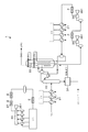
- the NG liquefier 1 shown in FIG. 1 precools the NG from which the impurities have been removed by the pre-treatment by the pre-cooling heat exchanger 31, separates the gas and liquid in the scrub column 32, and then removes the cryogenic main heat exchanger (MCHE: Liquefaction and supercooling at Main Cryogenic Heat Exchanger) 33 to obtain LNG.
- MCHE cryogenic main heat exchanger
- the liquid subjected to gas-liquid separation in the scrub column 32 is rectified by the rectification unit 34, and the light component separated in the rectification is sent to the MCHE 33 to form LNG.
- the NG liquefier 1 includes the outlet side of the C3 refrigerant compressor 35 that compresses the C3 refrigerant that performs precooling of the NG in the precooling heat exchanger 31, and the mixed refrigerant (MR: Mixed Refrigerant) used in the MCHE 33.
- MR Mixed Refrigerant
- a large number of ACHEs (heat exchangers) are provided at the outlet side of the MR compressor 36 for compression.
- the C3 refrigerant is also used as a refrigerant for cooling the MR in the MR cooler 37.
- FIG. 1 shows an example in which the C3 refrigerant compressor 35 and the MR compressor 36 are driven using gas turbines (G / T) 351 and 361.
- the ACHE 2 has a structure in which a rotationally driven fan 21 is provided on the upper side or the lower side of a tube bundle (not shown) obtained by bundling a large number of tubes in which C3 refrigerant and MR flow.
- the tube bundle is open at the top and bottom, and the cooling air is cooled by flowing cooling air from the bottom to the top through the gap between the adjacent tubes. Therefore, when the temperature of the cooling air taken into ACHE 2 rises, the ability to cool the refrigerant decreases.
- a large number of ACHEs 2 provided in the NG liquefier 1 are, for example, NG and various refrigerants (liquefaction refrigerant and pre-cooling refrigerant) exchanged between the devices constituting the NG liquefier 1. It arranges along the upper surface of the pipe rack 41 holding several piping 42 in which the fluid flows.
- a large number of devices constituting the NG liquefier 1 are put together in main process units such as pre-treatment of NG, pre-cooling, liquefaction, and supercooling, and arranged adjacent to the above-mentioned pipe rack 41.
- a pipe rack 41 provided with a large number of ACHEs 2 on the upper surface side and a group of equipment groups provided adjacent to the pipe rack 41 are also referred to as “modules”.
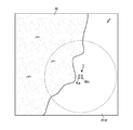
- the NG liquefaction apparatus 1 receives the NG transported from the well source via the pipeline, liquefies in the process illustrated in FIG. 1, and temporarily stores the LNG for shipping to an LNG tanker etc. Disburses LNG towards the tank to For this reason, as schematically shown in FIG. 2, the NG liquefaction apparatus 1 may be provided near the sea where LNG is shipped.
- the NG liquefying device 1 is configured by two sets of modules 4 a and 4 b in which an equipment group is provided adjacent to each of two pipe racks 41 configured in an elongated rectangular shape when viewed from the upper surface side. ing.
- the modules 4a and 4b are arranged adjacent to each other with their long sides oriented along the coastline and intersecting the coastline.
- a module provided at a position near the sea shown in FIGS. 2 and 3 is referred to as “sea side module 4 a”
- a module provided at a position far from the sea is referred to as “land side module 4 b”.
- the wind direction may change so that the wind periodically blows from, for example, a specific time of day or a direction determined in a specific season of the year.
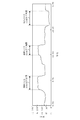
- FIG. 4 shows a typical example of the change of the wind direction of the wind blowing on the site where the NG liquefier 1 is provided.
- the horizontal axis in FIG. 4 represents time, and the vertical axis represents the wind direction (360 ° in which the north direction is 0 °).
- a time zone in which land wind blows from the land side to the sea side exists so as to intersect the long side of the sea side module 4a and the land side module 4b for several hours at night.
- HAR Hot Air Recirculation
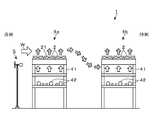
- FIG. 5 is an explanatory view schematically showing a generation mechanism of HAR in ACHE2.
- FIG. 4 shows a state in which the pipe rack 41 provided in the sea side module 4a and the land side module 4b is viewed from the side which intersects the direction in which the modules 4a and 4b are arranged.
- positioned adjacent to the pipe rack 41 is abbreviate
- the sea side module 4a and the land side module 4b in the positional relationship shown in FIG. 5 for example, when the sea wind from the sea side to the land side shown in FIG. 3 blows, the sea side module 4a located in the windward is provided.
- the high temperature exhaust air discharged from ACHE 2 flows toward the downwind land side module 4b.
- a part of the high temperature exhaust air is taken in as cooling air for the ACHE 2 on the land side module 4 b side to generate HAR.
- the cooling capacity of the ACHE 2 may be reduced.
- the HAR may also occur in the C3 refrigerant compressor 35 and the G / Ts 351 and 361 that drive the MR compressor 36.
- HAR may occur when part of the exhaust air from the ACHE 2 provided in the sea side module 4 a and the land side module 4 b flows into the air supply ducts of the G / Ts 351 and 361.
- part of the high temperature air exhausted from one of the C3 refrigerant compressor 35 and the MR compressor 36 from the G / T 351 or 361 may flow into the air supply duct of the other G / T 361 or 351. In such a case, the output of each of the G / Ts 361 and 351 may be reduced, and the circulation amount of the C3 refrigerant or the MR may be reduced.
- each HAR occurs in the time zone where the sea breeze or land breeze is shown in FIG. 3 (described as “HAR generation period” in FIG. 4).
- the HAR generated in any of the ACHE 2 and the G / Ts 351 and 361 affects the output of the G / Ts 351 and 361 for driving the respective compressors 35 and 36.
- FIG. 6 a mechanism for causing the generation of HAR to cause the output increase of the G / Ts 351 and 361 will be described with an example of the G / T 351 of the C3 refrigerant compressor 35.
- FIG. 6 (A) shows the contents of the state change associated with the occurrence of HAR
- FIG. 6 (B) is a condenser of the C3 refrigerant compressor 35, G / T 351 and C3 refrigerant in the NG liquefier 1 ACHE2 is shown extracted.
- FIG. 6 (B) is a condenser of the C3 refrigerant compressor 35, G / T 351 and C3 refrigerant in the NG liquefier 1 ACHE2 is shown extracted.
- the output of G / T 351 increases with the occurrence of HAR, and when the output reaches the upper limit value (when the load of C3 refrigerant compressor 35 reaches the upper limit load), G / T 351
- the emergency stop (trip) mechanism operates to cause the C3 refrigerant compressor 35 to stop.
- the C3 refrigerant compressor 35 stops the entire operation of the NG liquefier 1 must be stopped, and a large opportunity loss occurs.
- the output of G / T 351 is lowered in anticipation of the increase in output during the occurrence of HAR, and the increase in output due to HAR occurs Even if this is the case, operation adjustment is required to prevent the output of the G / T 351 from reaching the upper limit value.
- the output reduction of G / T 351 leads to the decrease of the circulation amount of C3 refrigerant, that is, the decrease of the precooling capacity of NG, and the occurrence of the opportunity loss that the production of LNG can not be increased It becomes a factor.
- the operation method of the NG liquefaction apparatus 1 is based on the result of acquiring the weather data of the area where the NG liquefaction apparatus 1 is installed.
- the operation adjustment of the NG liquefier 1 is performed.
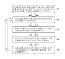
- the details of the operation method will be described with reference to FIGS. 7 and 8.
- the predicted value of the temperature of is determined (process P1 in FIG. 7: analysis step).
- the exhaust air discharged from ACHE 2 provided in the above-mentioned sea side module 4 a is for cooling ACHE 2 provided in the land side module 4 b.
- the temperature prediction of the cooling air taken in by ACHE 2 of the land side module 4b is performed in consideration of the HAR taken in again as air.
- the exhaust air from the ACHE 2 or the exhaust air from one of the G / Ts 361 and 351 of the C3 refrigerant compressor 35 and the MR compressor 36 takes into consideration the HAR taken into the other side G / Ts 351 and 361 In this state, the temperature of air taken into each of the G / Ts 351 and 361 may be predicted.
- the numerical analysis is a known numerical fluid dynamics analysis (CFD: Computational Fluid Dynamics) that reproduces the flow of air using finite element method, finite volume method, finite difference method, etc., temperature, wind direction, wind speed, each position
- CFD numerical Fluid dynamics analysis
- analysis methods using known multivariate analysis such as multiple regression analysis for determining a statistical correlation with the temperature of air taken into ACHE 2 and G / T 351, 361 can be exemplified.
- the process state of the NG liquefier 1 (the operating state of the plant) such as the processing amount of NG or the circulating amount of refrigerant is reflected by a known process simulator A simulation is performed to obtain the cooling capacity of each ACHE 2 and the load of the C3 refrigerant compressor 35 and the MR compressor 36 (that is, the outputs of G / T 351 and 361) for each air temperature, and the temperature of the air taken in and the C3 refrigerant compressor 35, the correlation of load changes of the MR compressor 36 is determined in advance.
- the correlation between the temperature of the air taken into each ACHE2 and G / T 351, 361 and the load change of the C3 refrigerant compressor 35 and the MR compressor 36 determined by the numerical analysis is the weather condition (temperature , Wind direction, wind speed), and stored in a computer, a storage unit of a control system that controls the operation of the NG liquefier 1 or the like.
- the wind direction from the meteorological observation facility provided within an area ranging from several kilometers to several tens of kilometers from the site where the NG liquefaction apparatus 1 is installed.
- the actual wind speed may be acquired, and the wind direction and the wind speed of the wind blowing in the premises of the NG liquefaction device 1 may be estimated based on these actual wind measurement values.
- the data in the said site can be easily acquired about temperature, it is not necessary to necessarily estimate from the result measured in the area away from the site.
- meteorological data is not limited to the case of acquiring based on the measurement results of the temperature and the wind direction and the wind speed, and may be acquired from the result of meteorological simulation.
- the weather analysis model created in the execution of the weather simulation, the computational fluid dynamics analysis by CFD, and the method of obtaining the temperature and wind direction of the predetermined area and the wind speed from this analysis result international publication WO2014 / 020778, WO2014 / 021236 Methods that are disclosed in detail in When utilizing the NG liquefier 1 for operation adjustment, it is possible to reproduce, for example, the change in wind direction described using FIG. 4 by performing weather simulation for each period divided into several hours per day. .
- the load of the C3 refrigerant compressor 35 and the MR compressor 36 is predicted from the specified predicted value of the temperature and the correlation between the temperature of the air taken in and the load change of the C3 refrigerant compressor 35 and the MR compressor 36.
- Judgment step (2) the output of G / T 351, 361 rises to the extent to the upper limit value described using the state S3 of FIG. You can predict what to do.
- the processing amount of NG processed in the NG liquefier 1 may be reduced.
- it circulates between each cooler (pre-cooling heat exchanger 31, MCHE 33, MR cooler 37) and each compressor 35, 36 which perform precooling of NG, liquefaction, and cooling of MR in the NG liquefier 1
- the amount of circulating refrigerant (C3 refrigerant, MR) may be reduced.
- the operation of the C3 refrigerant compressors 35 and 36 can be continued in a stable state even when the HAR occurs. Even when the operation adjustment described above is performed, it is possible to significantly reduce the opportunity loss compared to the case where the processing amount of NG and the circulating amount of refrigerant are kept low throughout the year in anticipation of HAR occurrence. .
- the above-described operation adjustment may be performed automatically, for example, by incorporating a control system that executes the processes P2 to P5 into an APC (Advanced Process Control) system or the like.
- the operator determines whether the operation adjustment is necessary or not and the simulation of the operation adjustment amount in the processes P2 to P4 and the process P5 is executed offline using a computer, and the NG process and the refrigerant circulation amount reflecting the operation adjustment amount are Operation adjustment may be performed by inputting to a DCS (Distributed Control System).
- DCS Distributed Control System
- the following effects can be obtained. Since the necessity of the operation adjustment of the NG liquefier 1 is judged by predicting the temperature of the air taken into ACHE 2 according to the result of acquiring the weather data and predicting the load of the refrigerant compressor, the occurrence of HAR, etc. Operation adjustment can be performed according to changes in weather conditions. As a result, the NG liquefier 1 can be operated stably and efficiently.
- the present invention can also be applied to the NG liquefier 1 including the C3 refrigerant compressor 35 and the MR compressor 36 which are driven.
- the present invention can also be applied to the NG liquefaction apparatus 1 including the C3 refrigerant compressor 35 and the MR compressor 36, which are driven by using the G / T and the auxiliary motor.
- the process configuration of the NG liquefier 1 to which the present invention can be applied is not limited to that illustrated in FIG.
- the process described with reference to FIG. 7 is applied to operation adjustment for preventing the MR compressor 36 from reaching the upper limit load. It is also good.
Landscapes
- Engineering & Computer Science (AREA)
- Mechanical Engineering (AREA)
- General Engineering & Computer Science (AREA)
- Physics & Mathematics (AREA)
- Thermal Sciences (AREA)
- Chemical & Material Sciences (AREA)
- Oil, Petroleum & Natural Gas (AREA)
- Chemical Kinetics & Catalysis (AREA)
- General Chemical & Material Sciences (AREA)
- Separation By Low-Temperature Treatments (AREA)
Abstract
Description
この点、例えば特許文献1、2には、NG液化装置(液化プラント:以下の特許文献1、2の説明において括弧内の用語は、これらの特許文献にて用いられている用語である)の空気利用装置から排出される温められた空気が循環して再度利用されることに伴う能力低下を回避するために、NG液化装置が設けられる敷地(領域)の風向や温度などの気象条件を気象シミュレーションにより再現する技術が記載されている。
このため、実際にNG液化装置が設けられている敷地内にて経時的に変化する気象条件に応じ、NG液化装置の運転調整を行う技術は開示されていない。
前記天然ガス液化装置が設置されている敷地の気温、及び当該敷地に吹く風の風向、風速の組み合わせである気象条件を変化させた条件下で、前記熱交換器群内の空冷式熱交換器から排出された排気空気が再び冷却用空気として取り込まれる場合を考慮し、当該熱交換器群内の空冷式熱交換器に取り込まれる冷却用空気の温度の予測値を、数値解析により求める解析工程と、
前記敷地の気温、当該敷地に吹く風の風向、風速に係る気象データを取得する気象データ取得工程と、
取得した前記気象データと対応する冷却用空気の温度の予測値を特定し、特定された予測値、及び前記予測値を用いて求めたプラントの運転状態に基づき、前記冷媒の冷却能力変化に伴う前記圧縮機の負荷変化を予測し、前記天然ガス液化装置の運転調整の要否を判断する判断工程と、を含み、
前記気象データ取得工程と判断工程とを繰り返し実施することを特徴とする。
(a)前記判断工程にて、前記圧縮機の負荷が、設定された上限負荷以上となることが予測された場合に、当該圧縮機の負荷を低減するための天然ガス液化装置の運転調整を行う負荷低減工程を含むこと。
(b)前記天然ガス液化装置の運転調整は、当該天然ガス液化装置にて処理される天然ガスの処理量の増減、及び/または前記天然ガス液化装置内の被冷却流体の冷却器と、前記圧縮機との間を循環する冷媒の循環量の増減であること。
(c)前記圧縮機はガスタービン圧縮機であり、前記解析工程では、さらに、前記排気空気が前記ガスタービン圧縮機を駆動するガスタービンに取り込まれる場合を考慮し、当該ガスタービンに取り込まれる空気の温度の予測値を、数値解析により求め、前記判断工程では、さらに前記気象データに対応する前記ガスタービンに取り込まれる空気の温度の予測値を特定し、この特定された予測値も含めて当該ガスタービン圧縮機の負荷変化を予測すること。
(d)前記気象データは、気象シミュレーションを行って得られた予測値であること。
図1に示すNG液化装置1は、前処理により不純物が除去されたNGを予冷熱交換器31により予冷却し、スクラブカラム32にて気液分離した後、極低温主熱交換器(MCHE:Main Cryogenic Heat Exchanger)33にて液化、過冷却してLNGを得る。スクラブカラム32にて気液分離された液体は、精留部34にて精留され、精留の際に分離された軽質成分はMCHE33へと送られてLNGとなる。
図1には、ガスタービン(G/T)351、361を用いてC3冷媒圧縮機35やMR圧縮機36を駆動する例を示してある。
従って、ACHE2に取り込まれる冷却用空気の温度が上昇すると、冷媒を冷却する能力が低下する。
例えばNG液化装置1は、井戸元からパイプラインを介して輸送されてきたNGを受け入れ、図1に例示したプロセスにて液化した後、LNGタンカーなどへの出荷のためにLNGを一時的に貯蔵するタンクに向けてLNGを払い出す。このため、図2に模式的に示すように、NG液化装置1はLNGの出荷が行われる海の近くに設けられる場合がある。
各モジュール4a、4bは、その長辺を海岸線に沿った方向に向け、海岸線と交差する方向に向けて隣り合うように配置されている。以下、図2、3に示した、海に近い位置に設けられたモジュールを「海側モジュール4a」、海から遠い位置に設けられたモジュールを「陸側モジュール4b」という。
図4は、NG液化装置1が設けられている敷地に吹く風の1日の風向変化の典型例を示している。図4の横軸は時刻、縦軸は風向(北向きを0°とした360°表示)を示している。図4によると、朝方と正午過ぎの数時間ずつ、海側モジュール4a、陸側モジュール4bの長辺と交差するように海側から陸側へと海風が吹く時間帯が存在している。また、夜間の数時間は海側モジュール4a、陸側モジュール4bの長辺と交差するように陸側から海側へと陸風が吹く時間帯が存在している。
そして、ACHE2、G/T351、361のいずれで発生するHARについても、各圧縮機35、36を駆動するG/T351、361の出力に影響を及ぼす。以下、図6を参照しながら、HARの発生がG/T351、361の出力上昇を引き起こすメカニズムについて、C3冷媒圧縮機35のG/T351の例を挙げて説明する。
はじめにACHE2側のHARの影響について説明する。例えば、図4中に海風によるHAR発生期間と記載されている時間帯にHARが発生すると、C3冷媒の凝縮器であって、陸側モジュール4b側に設けられているACHE2に取り込まれる空気(a)の温度が上昇する(図6(A)の状態S11)。
前記G/T351にてHARが発生すると、G/T351に取り込まれる空気(e)の温度が上昇する(図6(A)の状態S21)。空気の温度上昇に伴い、空気の密度が低下し、G/T351(f)の出力が低下する(図6(A)の状態S22)。このとき、HAR発生前と同じC3冷媒の循環量を維持するためにはG/T351(f)の出力を上げ、上限出力へと近づける必要がある(図6(A)の状態S3)。
しかしながらG/T351の出力ダウンは、C3冷媒の循環量の減少、即ち、NGの予冷能力の低下につながり、機器余力があるにも係らずLNGの生産量を増やすことができないという機会損失の発生要因となる。
以下、図7、8を参照しながら当該運転方法の詳細について説明する。
このとき、数値解析の際に設定する風の風向によっては、既述の海側モジュール4aに設けられているACHE2から排出された排気空気が、陸側モジュール4bに設けられているACHE2の冷却用空気として再び取り込まれるHARを考慮した状態で、当該陸側モジュール4bのACHE2に取り込まれる冷却用空気の温度予測が行われることになる。
例えば図5に示すように、これらの気象データは、NG液化装置1が設置されている敷地内に気象ポール5を設置し、当該気象ポール5から取得してもよい。
NG液化装置1の運転調整への活用にあたっては、例えば1日を数時間ごとに区切った各期間について気象シミュレーションを実施することにより、図4を用いて説明した風向変化などを再現することができる。
この結果、取得した気象データの条件下でHARが発生する場合には、図6(A)の状態S3を用いて説明した上限値に対して、G/T351、361の出力がどの程度まで上昇するのかを予測することができる。
例えばC3冷媒圧縮機35、MR圧縮機36の負荷の予測値が、G/T351、361にて緊急停止が発生するおそれがある上限負荷以上となることが予測された場合には、これらC3冷媒圧縮機35、MR圧縮機36の負荷を低減するためのNG液化装置1の運転調整を行う(負荷低減工程)。
なお、上述の運転調整を実施する場合であっても、HAR発生を見越して、NGの処理量や冷媒の循環量を通年で低く抑える場合に比べて大幅な機会損失の低減を図ることができる。
始めに、図8(d)に示すNGの処理量の左端の状態において、同図(c)に示すように上限負荷未満の負荷にてC3冷媒圧縮機35の運転が行われているとする。
この結果、図8(c)中に破線で示した、C3冷媒圧縮機35の負荷が上限負荷を超えて上昇する状態を回避し、安定してC3冷媒圧縮機35の運転を継続することができる。
2 ACHE
35 C3圧縮機
351 G/T
36 MR圧縮機
361 G/T
4a 海側モジュール
4b 陸側モジュール
41 パイプラック
5 気象ポール
Claims (5)
- 天然ガスの液化を行う際に用いられる冷媒を圧縮するための圧縮機と、前記圧縮機で圧縮された冷媒を冷却するための複数の空冷式熱交換器を含む熱交換器群と、を備えた天然ガス液化装置の運転方法において、
前記天然ガス液化装置が設置されている敷地の気温、及び当該敷地に吹く風の風向、風速の組み合わせである気象条件を変化させた条件下で、前記熱交換器群内の空冷式熱交換器から排出された排気空気が再び冷却用空気として取り込まれる場合を考慮し、当該熱交換器群内の空冷式熱交換器に取り込まれる冷却用空気の温度の予測値を、数値解析により求める解析工程と、
前記敷地の気温、当該敷地に吹く風の風向、風速に係る気象データを取得する気象データ取得工程と、
取得した前記気象データと対応する冷却用空気の温度の予測値を特定し、特定された予測値、及び前記予測値を用いて求めたプラントの運転状態に基づき、前記冷媒の冷却能力変化に伴う前記圧縮機の負荷変化を予測し、前記天然ガス液化装置の運転調整の要否を判断する判断工程と、を含み、
前記気象データ取得工程と判断工程とを繰り返し実施することを特徴とする天然ガス液化装置の運転方法。 - 前記判断工程にて、前記圧縮機の負荷が、設定された上限負荷以上となることが予測された場合に、当該圧縮機の負荷を低減するための天然ガス液化装置の運転調整を行う負荷低減工程を含むことを特徴とする請求項1に記載の天然ガス液化装置の運転方法。
- 前記天然ガス液化装置の運転調整は、当該天然ガス液化装置にて処理される天然ガスの処理量の増減、及び/または前記天然ガス液化装置内の被冷却流体の冷却器と、前記圧縮機との間を循環する冷媒の循環量の増減であることを特徴とする請求項1に記載の天然ガス液化装置の運転方法。
- 前記圧縮機はガスタービン圧縮機であり、前記解析工程では、さらに、前記排気空気が前記ガスタービン圧縮機を駆動するガスタービンに取り込まれる場合を考慮し、当該ガスタービンに取り込まれる空気の温度の予測値を、数値解析により求め、前記判断工程では、さらに前記気象データに対応する前記ガスタービンに取り込まれる空気の温度の予測値を特定し、この特定された予測値も含めて当該ガスタービン圧縮機の負荷変化を予測することを特徴とする請求項1に記載の天然ガス液化装置の運転方法。
- 前記気象データは、気象シミュレーションを行って得られた予測値であることを特徴とする請求項1に記載の天然ガス液化装置の運転方法。
Priority Applications (3)
| Application Number | Priority Date | Filing Date | Title |
|---|---|---|---|
| PCT/JP2017/041685 WO2019097728A1 (ja) | 2017-11-20 | 2017-11-20 | 天然ガス液化装置の運転方法 |
| MYPI2020002039A MY205474A (en) | 2017-11-20 | 2017-11-20 | Method of operating natural gas liquefaction apparatus |
| AU2017436646A AU2017436646B2 (en) | 2017-11-20 | Method of operating natural gas liquefaction apparatus |
Applications Claiming Priority (1)
| Application Number | Priority Date | Filing Date | Title |
|---|---|---|---|
| PCT/JP2017/041685 WO2019097728A1 (ja) | 2017-11-20 | 2017-11-20 | 天然ガス液化装置の運転方法 |
Publications (1)
| Publication Number | Publication Date |
|---|---|
| WO2019097728A1 true WO2019097728A1 (ja) | 2019-05-23 |
Family
ID=66539404
Family Applications (1)
| Application Number | Title | Priority Date | Filing Date |
|---|---|---|---|
| PCT/JP2017/041685 Ceased WO2019097728A1 (ja) | 2017-11-20 | 2017-11-20 | 天然ガス液化装置の運転方法 |
Country Status (2)
| Country | Link |
|---|---|
| MY (1) | MY205474A (ja) |
| WO (1) | WO2019097728A1 (ja) |
Cited By (3)
| Publication number | Priority date | Publication date | Assignee | Title |
|---|---|---|---|---|
| WO2020240696A1 (ja) * | 2019-05-28 | 2020-12-03 | 日揮グローバル株式会社 | 製造プラントの稼働解析方法 |
| TWI738016B (zh) * | 2019-06-26 | 2021-09-01 | 元翎精密工業股份有限公司 | 液態氣體充填之智能化學習機制與自適應調節系統 |
| US12092395B2 (en) | 2019-07-10 | 2024-09-17 | Jgc Corporation | Operation analysis method for natural gas plant |
Citations (4)
| Publication number | Priority date | Publication date | Assignee | Title |
|---|---|---|---|---|
| JPH05196349A (ja) * | 1991-07-31 | 1993-08-06 | Air Prod And Chem Inc | ガス液化プロセスのコントロールシステム |
| WO2014021236A1 (ja) * | 2012-07-31 | 2014-02-06 | 日揮株式会社 | 気象再現方法、気象再現装置及び空気利用装置 |
| WO2014103332A1 (ja) * | 2012-12-28 | 2014-07-03 | 日揮株式会社 | 液化ガス製造設備 |
| JP2017032146A (ja) * | 2014-01-31 | 2017-02-09 | 日揮株式会社 | 液化ガス製造設備及び液化ガス製造方法 |
-
2017
- 2017-11-20 WO PCT/JP2017/041685 patent/WO2019097728A1/ja not_active Ceased
- 2017-11-20 MY MYPI2020002039A patent/MY205474A/en unknown
Patent Citations (5)
| Publication number | Priority date | Publication date | Assignee | Title |
|---|---|---|---|---|
| JPH05196349A (ja) * | 1991-07-31 | 1993-08-06 | Air Prod And Chem Inc | ガス液化プロセスのコントロールシステム |
| WO2014021236A1 (ja) * | 2012-07-31 | 2014-02-06 | 日揮株式会社 | 気象再現方法、気象再現装置及び空気利用装置 |
| WO2014020778A1 (ja) * | 2012-07-31 | 2014-02-06 | 日揮株式会社 | 気象再現方法、気象再現装置、及び空気利用装置 |
| WO2014103332A1 (ja) * | 2012-12-28 | 2014-07-03 | 日揮株式会社 | 液化ガス製造設備 |
| JP2017032146A (ja) * | 2014-01-31 | 2017-02-09 | 日揮株式会社 | 液化ガス製造設備及び液化ガス製造方法 |
Non-Patent Citations (2)
| Title |
|---|
| KUBOTA, KEI: "Hot Air Recirculation Phenomenon in an Air Cooled LNG Plant", JGC TECHNICAL JOURNAL, vol. 3, no. 2, 2014, pages 1 - 8, XP055610233 * |
| SITI FARHANA BT M SHAARI ET AL.: "Understanding of Hot Air Recirculation Phenomena in Air-Cooled Base Load LNG Plant", LNG 17CONFERENCE GAS TECHNOLOGY INSTITUTE, 2013, pages 1 - 15, XP055610231, Retrieved from the Internet <URL:http://www.gastechnology.org/Training/Documents/LNG17-proceedings/Materials-6-Siti_Farhana_M_Shaari.pdf> [retrieved on 20180126] * |
Cited By (5)
| Publication number | Priority date | Publication date | Assignee | Title |
|---|---|---|---|---|
| WO2020240696A1 (ja) * | 2019-05-28 | 2020-12-03 | 日揮グローバル株式会社 | 製造プラントの稼働解析方法 |
| US12152479B2 (en) | 2019-05-28 | 2024-11-26 | Jgc Corporation | Operation analysis method for production plant |
| AU2019448524B2 (en) * | 2019-05-28 | 2025-03-27 | Jgc Corporation | Operation analysis method for production plant |
| TWI738016B (zh) * | 2019-06-26 | 2021-09-01 | 元翎精密工業股份有限公司 | 液態氣體充填之智能化學習機制與自適應調節系統 |
| US12092395B2 (en) | 2019-07-10 | 2024-09-17 | Jgc Corporation | Operation analysis method for natural gas plant |
Also Published As
| Publication number | Publication date |
|---|---|
| AU2017436646A1 (en) | 2019-06-06 |
| MY205474A (en) | 2024-10-22 |
Similar Documents
| Publication | Publication Date | Title |
|---|---|---|
| US8783061B2 (en) | Apparatus and method for optimizing a natural gas liquefaction train having a nitrogen cooling loop | |
| CA2894789C (en) | Liquefied gas production facility | |
| RU2685460C1 (ru) | Способ автоматического поддержания температурного режима технологических процессов установки низкотемпературной сепарации газа с применением аппаратов воздушного охлаждения в условиях крайнего севера | |
| WO2019097728A1 (ja) | 天然ガス液化装置の運転方法 | |
| WO2017073433A1 (ja) | ヒートポンプ | |
| Shi et al. | Evaluation of energy saving potential of HVAC system by operation data with uncertainties | |
| CN102483695A (zh) | 在具有平行序列的气体装置中的制冷系统控制方法 | |
| US20220196323A1 (en) | Cryogenic Containment System | |
| JP6360987B1 (ja) | 天然ガス液化装置、及び天然ガス液化装置の設計方法 | |
| Liu et al. | Optimal setting parameters of cooling system under different climate zones for data center energy efficiency | |
| Zhou et al. | Multi-criteria assessments of increasing supply air temperature in tropical data center | |
| AU2019448524B2 (en) | Operation analysis method for production plant | |
| AU2017341387B2 (en) | System for treating and cooling a hydrocarbon stream | |
| Ajour et al. | Optimizing and simulating cooling of electric transformer room utilizing genetic algorithm to reduce electricity/water demand by incorporating borehole ground heat exchangers | |
| AU2017436646B2 (en) | Method of operating natural gas liquefaction apparatus | |
| JP2020183856A (ja) | 機械学習装置、空調システム及び機械学習方法 | |
| JP4563269B2 (ja) | タービン型冷凍機の冷凍能力制御装置 | |
| Filimoshina | JOURNAL OF MINING INSTITUTE | |
| CN116502450A (zh) | 一种基于云数据平台大数据寻优的煤电机组冷端优化方法 | |
| Bagade et al. | Optimized design of diesel generators based chilled water cooling system for intelligent hospitals and hotels | |
| CN108106290A (zh) | 油冷机的压缩机运行频率控制方法、系统及油冷机 | |
| Filimoshina | Development of an engineering methodology for determining the standard consumption of electricity by air coolers | |
| JP5549362B2 (ja) | 熱源システムおよび熱供給方法 | |
| EP4267898A1 (en) | Cryogenic containment system | |
| US20260013081A1 (en) | System and method for providing supplemental power and cooling to one or more server racks |
Legal Events
| Date | Code | Title | Description |
|---|---|---|---|
| ENP | Entry into the national phase |
Ref document number: 2017436646 Country of ref document: AU Date of ref document: 20171120 Kind code of ref document: A |
|
| 121 | Ep: the epo has been informed by wipo that ep was designated in this application |
Ref document number: 17932145 Country of ref document: EP Kind code of ref document: A1 |
|
| WWE | Wipo information: entry into national phase |
Ref document number: DZP2020000244 Country of ref document: DZ |
|
| 122 | Ep: pct application non-entry in european phase |
Ref document number: 17932145 Country of ref document: EP Kind code of ref document: A1 |
|
| NENP | Non-entry into the national phase |
Ref country code: JP |