WO2019097649A1 - User terminal and wireless communication method - Google Patents
User terminal and wireless communication method Download PDFInfo
- Publication number
- WO2019097649A1 WO2019097649A1 PCT/JP2017/041361 JP2017041361W WO2019097649A1 WO 2019097649 A1 WO2019097649 A1 WO 2019097649A1 JP 2017041361 W JP2017041361 W JP 2017041361W WO 2019097649 A1 WO2019097649 A1 WO 2019097649A1
- Authority
- WO
- WIPO (PCT)
- Prior art keywords
- frequency band
- bwp
- frequency
- pair
- user terminal
- Prior art date
Links
Images


Classifications
-
- H—ELECTRICITY
- H04—ELECTRIC COMMUNICATION TECHNIQUE
- H04L—TRANSMISSION OF DIGITAL INFORMATION, e.g. TELEGRAPHIC COMMUNICATION
- H04L5/00—Arrangements affording multiple use of the transmission path
- H04L5/0001—Arrangements for dividing the transmission path
- H04L5/0003—Two-dimensional division
- H04L5/0005—Time-frequency
- H04L5/0007—Time-frequency the frequencies being orthogonal, e.g. OFDM(A), DMT
- H04L5/001—Time-frequency the frequencies being orthogonal, e.g. OFDM(A), DMT the frequencies being arranged in component carriers
-
- H—ELECTRICITY
- H04—ELECTRIC COMMUNICATION TECHNIQUE
- H04L—TRANSMISSION OF DIGITAL INFORMATION, e.g. TELEGRAPHIC COMMUNICATION
- H04L27/00—Modulated-carrier systems
- H04L27/26—Systems using multi-frequency codes
- H04L27/2601—Multicarrier modulation systems
- H04L27/2602—Signal structure
- H04L27/26025—Numerology, i.e. varying one or more of symbol duration, subcarrier spacing, Fourier transform size, sampling rate or down-clocking
-
- H—ELECTRICITY
- H04—ELECTRIC COMMUNICATION TECHNIQUE
- H04L—TRANSMISSION OF DIGITAL INFORMATION, e.g. TELEGRAPHIC COMMUNICATION
- H04L5/00—Arrangements affording multiple use of the transmission path
- H04L5/003—Arrangements for allocating sub-channels of the transmission path
- H04L5/0078—Timing of allocation
- H04L5/0082—Timing of allocation at predetermined intervals
-
- H—ELECTRICITY
- H04—ELECTRIC COMMUNICATION TECHNIQUE
- H04L—TRANSMISSION OF DIGITAL INFORMATION, e.g. TELEGRAPHIC COMMUNICATION
- H04L5/00—Arrangements affording multiple use of the transmission path
- H04L5/0091—Signaling for the administration of the divided path
- H04L5/0094—Indication of how sub-channels of the path are allocated
-
- H—ELECTRICITY
- H04—ELECTRIC COMMUNICATION TECHNIQUE
- H04L—TRANSMISSION OF DIGITAL INFORMATION, e.g. TELEGRAPHIC COMMUNICATION
- H04L5/00—Arrangements affording multiple use of the transmission path
- H04L5/0091—Signaling for the administration of the divided path
- H04L5/0096—Indication of changes in allocation
- H04L5/0098—Signalling of the activation or deactivation of component carriers, subcarriers or frequency bands
-
- H—ELECTRICITY
- H04—ELECTRIC COMMUNICATION TECHNIQUE
- H04L—TRANSMISSION OF DIGITAL INFORMATION, e.g. TELEGRAPHIC COMMUNICATION
- H04L5/00—Arrangements affording multiple use of the transmission path
- H04L5/14—Two-way operation using the same type of signal, i.e. duplex
- H04L5/1469—Two-way operation using the same type of signal, i.e. duplex using time-sharing
-
- H—ELECTRICITY
- H04—ELECTRIC COMMUNICATION TECHNIQUE
- H04W—WIRELESS COMMUNICATION NETWORKS
- H04W72/00—Local resource management
- H04W72/04—Wireless resource allocation
- H04W72/044—Wireless resource allocation based on the type of the allocated resource
- H04W72/0453—Resources in frequency domain, e.g. a carrier in FDMA
-
- H—ELECTRICITY
- H04—ELECTRIC COMMUNICATION TECHNIQUE
- H04W—WIRELESS COMMUNICATION NETWORKS
- H04W72/00—Local resource management
- H04W72/20—Control channels or signalling for resource management
- H04W72/21—Control channels or signalling for resource management in the uplink direction of a wireless link, i.e. towards the network
-
- H—ELECTRICITY
- H04—ELECTRIC COMMUNICATION TECHNIQUE
- H04W—WIRELESS COMMUNICATION NETWORKS
- H04W72/00—Local resource management
- H04W72/04—Wireless resource allocation
- H04W72/044—Wireless resource allocation based on the type of the allocated resource
- H04W72/0446—Resources in time domain, e.g. slots or frames
Definitions
- the present invention relates to a user terminal and a wireless communication method in a next-generation mobile communication system.
- LTE Long Term Evolution
- Non-Patent Document 1 LTE-A (LTE-Advanced), FRA (Future Radio Access), 4G, 5G, 5G + (plus), NR ( Also referred to as New RAT), LTE Rel. 14, 15 and so on.
- downlink (DL: Downlink) and / or uplink (UL: Uplink) communication is performed with a subframe of 1 ms as a scheduling unit.
- DL Downlink
- UL Uplink
- the subframe is composed of 14 symbols of 15 kHz subcarrier spacing.
- the subframes are also referred to as transmission time intervals (TTIs) or the like.
- the user terminal (UE: User Equipment) is a DL data channel based on downlink control information (DCI: Downlink Control Information) (also referred to as DL assignment etc.) from a radio base station (for example, eNB: eNodeB). It controls reception of (for example, PDSCH: Physical Downlink Shared Channel, DL Shared Channel, etc.). Also, the user terminal controls transmission of a UL data channel (for example, PUSCH: also referred to as Physical Uplink Shared Channel, UL shared channel, etc.) based on DCI (also referred to as UL grant, etc.) from the radio base station.
- DCI Downlink Control Information
- E-UTRA Evolved Universal Terrestrial Radio Access
- E-UTRAN Evolved Universal Terrestrial Radio Access Network
- a user terminal is a control resource area (for example, control resource set (CORESET: control resource) which is a candidate area to which a DL control channel (for example, PDCCH: Physical Downlink Control Channel) is allocated. It is considered to receive (detect) DCI by monitoring (blind decoding)).
- CORESET control resource set
- PDCCH Physical Downlink Control Channel
- one or more partial frequency bands (Partial Band), bands within a carrier (also referred to as component carrier (CC) or system band etc.) It has been considered to use a width part (BWP: Bandwidth part, etc.) for DL and / or UL communication (DL / UL communication).
- CC component carrier
- BWP Bandwidth part, etc.
- one or more frequency bands for example, BWP
- BWP frequency band
- activation and / or deactivation of the frequency band can be performed. It is considered that activation / deactivation is performed.
- one or more BWPs are configured and wireless communication is performed by TDD (time division duplex) or FDD (frequency division duplex) using this BWP.
- TDD time division duplex
- FDD frequency division duplex
- UL BWP frequency band for UL
- DL BWP frequency band for DL
- DL / UL frequency band pair DL / UL BWP pair
- the present invention has been made in view of the foregoing points, and uses a DL / UL frequency band pair (DL / UL BWP pair) having a UL frequency band and a DL frequency set in the frequency direction in a carrier.
- An object of the present invention is to provide a user terminal and a wireless communication method that appropriately perform TDD wireless communication.
- One aspect of a user terminal is a transmitting / receiving unit that performs transmission / reception in TDD (Time Division Multiplexing) using a DL / UL frequency band pair having a UL frequency band and a DL frequency band set in a frequency direction in a carrier And a first DL / UL frequency band pair which shares a center frequency between the UL frequency band and the DL frequency band and is biased toward the upper limit frequency side or the lower limit frequency side in the carrier frequency band
- the bandwidth of at least one of the UL frequency band and the DL frequency band is wider than the bandwidth of the first DL / UL frequency band pair, and the at least one frequency band is the first DL / UL frequency band
- a control unit configured to switch between a second DL / UL frequency band pair including a pair of frequency bands and control the transmission and reception to be performed.
- TDD wireless communication is performed using a DL / UL frequency band pair (DL / UL BWP pair) having UL frequency bands and DL frequencies partially set in the frequency direction in a carrier. It can be done properly.
- FIGS. 1A-1C are diagrams showing an example of a BWP setting scenario.
- FIG. 2 is a diagram showing an example of control of activation / deactivation of BWP.
- FIG. 3 is a diagram illustrating an example of control of activation or deactivation of one or more BWPs in an S cell.
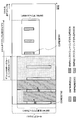
- FIG. 4 is a diagram for explaining TDD wireless communication using different DL / UL BWP pairs.
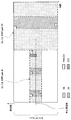
- FIG. 5 is a diagram for describing TDD wireless communication using a DL / UL BWP pair in the first aspect.
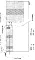
- FIG. 6 is a diagram for describing TDD wireless communication using a DL / UL BWP pair in the second aspect.
- FIG. 1A-1C are diagrams showing an example of a BWP setting scenario.
- FIG. 2 is a diagram showing an example of control of activation / deactivation of BWP.
- FIG. 3 is a diagram illustrating an example of control of activation or deactivation of one
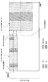
- FIG. 7 is a diagram for describing TDD wireless communication using a DL / UL BWP pair in the third aspect.
- FIG. 8 is a diagram for describing TDD wireless communication using a DL / UL BWP pair in the fourth aspect.
- FIG. 9 is a diagram for describing TDD wireless communication using a DL / UL BWP pair.
- FIG. 10 is a diagram for describing a modified example of TDD wireless communication using a DL / UL BWP pair.
- FIG. 11 is a diagram showing an example of a schematic configuration of a wireless communication system according to the present embodiment.
- FIG. 12 is a diagram showing an example of the entire configuration of the radio base station according to the present embodiment.
- FIG. 13 is a diagram showing an example of a functional configuration of the radio base station according to the present embodiment.
- FIG. 14 is a diagram showing an example of the entire configuration of the user terminal according to the present embodiment.
- FIG. 15 is a diagram showing an example of a functional configuration of a user terminal according to the present embodiment.
- FIG. 16 is a diagram showing an example of the hardware configuration of the radio base station and the user terminal according to the present embodiment.
- carriers for example, NR, 5G or 5G +
- carriers component carriers (CC: Component Carrier) having a wider bandwidth (for example, 100 to 800 MHz) than existing LTE systems (for example, LTE Rel. 8-13) It is considered to assign a carrier (also referred to as a cell or a system band).
- a user terminal also referred to as Wideband (WB) UE, single carrier WB UE, etc.
- WB Wideband
- UE single carrier WB UE
- each frequency band (for example, 50 MHz or 200 MHz) in the carrier is called a sub-band or bandwidth part (BWP) or the like.
- FIG. 1 is a diagram illustrating an example of a BWP setting scenario.
- FIG. 1A shows a scenario (Usage scenario # 1) in which one BWP is set as a user terminal in one carrier.
- a 200 MHz BWP is set in an 800 MHz carrier.
- the activation or deactivation of the BWP may be controlled.
- BWP activation means being in a usable state (or transitioning to the usable state), and activating BWP setting information (configuration) (BWP setting information) or It is also called validation.
- deactivation of the BWP means that the BWP is in an unusable state (or transits to the unusable state), and is also called deactivation or invalidation of BWP setting information.
- FIG. 1B shows a scenario (Usage scenario # 2) in which a plurality of BWPs are set in a user terminal in one carrier. As shown in FIG. 1B, at least a portion of the plurality of BWPs (eg, BWPs # 1 and # 2) may overlap. For example, in FIG. 1B, BWP # 1 is a partial frequency band of BWP # 2.
- At least one activation or deactivation of the plurality of BWPs may be controlled. Also, the number of BWPs activated at any given time may be limited (eg, only one BWP may be active at any given time). For example, in FIG. 1B, only one of BWP # 1 or # 2 is active at a certain time.
- BWP # 1 may be activated when data transmission / reception is not performed
- BWP # 2 may be activated when data transmission / reception is performed.
- switching from BWP # 1 to BWP # 2 may be performed, and when data transmission / reception is completed, switching from BWP # 2 to BWP # 1 may be performed.
- the user terminal does not have to constantly monitor BWP # 2, which has a wider bandwidth than BWP # 1, and can therefore reduce power consumption.
- the network (for example, a radio base station) may not assume that the user terminal receives and / or transmits outside the BWP in the active state.
- the user terminal supporting the entire carrier is not suppressed at all from receiving and / or transmitting a signal outside the BWP.
- FIG. 1C shows a scenario (Usage scenario # 3) in which a plurality of BWPs are set in different bands in one carrier.
- different numerologies may be applied to the plurality of BWPs.
- the neurology includes at least one of subcarrier spacing, symbol length, slot length, cyclic prefix (CP) length, slot (transmission time interval (TTI)) length, number of symbols per slot, etc. It may be one.
- BWPs # 1 and # 2 having different neurology are set for user terminals having the ability to transmit and receive in the entire carrier.
- at least one BWP configured for a user terminal may be activated or deactivated, and at one time, one or more BWPs may be active.
- BWP used for DL communication may be called DL BWP (frequency band for DL)
- BWP used for UL communication may be called UL BWP (frequency band for UL).
- DL BWP and UL BWP may overlap at least a part of frequency bands.
- BWP when the DL BWP and the UL BWP are not distinguished, they are collectively referred to as BWP.
- At least one of DL BWPs set in the user terminal may include a control resource region that is a candidate for assignment of a DL control channel (DCI).
- the control resource region is called a control resource set (CORESET), a control subband, a search space set, a search space resource set, a control region, a control subband, an NR-PDCCH region, etc. It is also good.
- the user terminal monitors one or more search spaces in CORESET to detect DCI for the user terminal.
- the search space is a common search space (CSS: Common Search Space) in which a common DCI (for example, group DCI or common DCI) is arranged for one or more user terminals and / or a user terminal-specific DCI (for example, DL assignment) And / or a UL grant) may be included in a user terminal (UE) specific search space (USS).
- CCS Common Search Space
- a common DCI for example, group DCI or common DCI
- UE user terminal specific search space
- the user terminal may receive CORESET configuration information (CORESET configuration information) using higher layer signaling (for example, RRC (Radio Resource Control) signaling or the like).
- the CORESET configuration information includes frequency resources (eg, number of RBs and / or start RB index) of each CORESET, time resources (eg, start OFDM symbol number), duration (duration), REG (resource element group) bundle size (eg It may indicate at least one of REG size), transmission type (eg, interleaving, non-interleaving), cycle (eg, monitor cycle per CORESET), and so on.
- FIG. 2 is a diagram showing an example of control of activation / deactivation of BWP.
- FIG. 2 assumes the scenario shown in FIG. 1B, the control of activation / deactivation of the BWP can be appropriately applied to the scenario shown in FIGS. 1A and 1C.
- CORESET # 1 is set in BWP # 1
- CORESET # 2 is set in BWP # 2.
- Each of CORESET # 1 and CORESET # 2 is provided with one or more search spaces.
- DCI for BWP # 1 and DCI for BWP # 2 may be located in the same search space, or may be located in different search spaces.
- the user terminal when BWP # 1 is in the active state, the user terminal is in CORESET # 1 in a predetermined cycle (for example, every one or more slots, every one or more minislots, or each predetermined number of symbols).
- the search space is monitored (blind decoding) to detect DCI for the user terminal.
- the DCI may include information (BWP information) indicating which BWP the DCI is for.
- the said BWP information is an index of BWP, for example, and should just be a predetermined field value in DCI.
- the BWP index information may be included in downlink scheduling DCI, may be included in uplink scheduling DCI, or may be included in common search space DCI. Good.
- the user terminal may determine the BWP for which the PDSCH or PUSCH is scheduled by the DCI based on the BWP information in the DCI.
- the user terminal when detecting a DCI for BWP # 2 in CORESET # 1, the user terminal deactivates BWP # 1 and activates BWP # 2.
- the user terminal receives a PDSCH scheduled to a predetermined time / frequency resource of DL BWP # 2 based on the DCI for BWP # 2 detected in CORESET # 1.
- the DCI for BWP # 1 and the DCI for BWP # 2 are detected at different timings in CORESET # 1
- a plurality of DCI of different BWPs may be detected at the same timing.
- a plurality of search spaces corresponding to each of a plurality of BWPs may be provided in the CORESET # 1
- a plurality of DCIs of different BWPs may be transmitted in the plurality of search spaces.
- the user terminal may monitor a plurality of search spaces in CORESET # 1 to detect a plurality of DCIs of different BWPs at the same timing.
- the user terminal When BWP # 2 is activated, the user terminal monitors the search space in CORESET # 2 in a predetermined cycle (for example, every one or more slots, every one or more minislots, or each predetermined number of symbols) (blind) Decode to detect DCI for BWP # 2.
- the user terminal may receive a PDSCH scheduled to a predetermined time / frequency resource of BWP # 2 based on the DCI for BWP # 2 detected in CORESET # 2.
- the predetermined time may not be present.
- BWP # 2 when BWP # 2 is activated with detection of DCI for BWP # 2 in CORESET # 1 as a trigger, BWP # 2 can be activated without explicit indication information, so Can be prevented from increasing overhead associated with
- the radio base station when the radio base station can not receive the delivery confirmation information (also referred to as HARQ-ACK, ACK / NACK or A / N, etc.) of the PDSCH in a predetermined period, the user terminal is for BWP # 2 activation. It is recognized that the detection of the DCI of the above has failed, and CORESET # 1 may retransmit the DCI for activation. Alternatively, although not shown in FIG. 2, a common CORESET may be provided for BWPs # 1 and # 2.
- the delivery confirmation information also referred to as HARQ-ACK, ACK / NACK or A / N, etc.
- the BWP may be deactivated. For example, in FIG. 2, the user terminal deactivates BWP # 2 and activates BWP # 1, since PDSCH is not scheduled for a predetermined period in DL BWP # 2.
- a data channel eg, PDSCH and / or PUSCH
- the user terminal may set a timer each time reception of a data channel (for example, PDSCH and / or PUSCH) is completed in the activated BWP, and may deactivate the BWP when the timer expires.
- the timer may be a common timer (also referred to as a joint timer or the like) between the DL BWP and the UL BWP, or may be an individual timer.
- the maximum number of BWPs that can be set per carrier may be predetermined. For example, in frequency division duplex (FDD) (Paired spectrum), up to four DL BWPs and up to four UL BWPs may be set per carrier.
- FDD frequency division duplex
- up to four DL BWPs and up to four UL BWPs may be set per carrier.
- TDD time division duplex
- DL BWP and UL BWP to be paired may have the same center frequency but different bandwidths.
- multiple carriers may be integrated (eg, carrier aggregation (CA: Carrier Aggregation) and / or dual connectivity (DC: Dual Connectivity) )).
- CA Carrier Aggregation
- DC Dual Connectivity
- one or more BWPs may be set in at least one of the plurality of carriers.
- the plurality of cells may include a primary cell (P cell: Primary Cell) and one or more secondary cells (S cell: Secondary Cell).
- the PCell corresponds to a single carrier (CC) and may include one or more BWPs.
- each S cell may correspond to a single carrier (CC) and may include one or more BWPs.
- Each BWP of the PCell may be provided with a common search space for a Random Access Channel Procedure (RACH). Similarly, each BWP of the PCell may be provided with a common search space for fallback, a common search space for paging, or a common search space for Remaining Minimum System Information (RMSI).
- RACH Random Access Channel Procedure
- RMSI Remaining Minimum System Information
- each BWP of one or more cells is provided with a common search space for PDCCH (group common PDCCH (group-common PDCCH)) common to one or more user terminals. It is also good.
- a specific BWP may be predetermined in the user terminal.
- BWP initial active BWP to which a PDSCH for transmitting system information (for example, RMSI: Remaining Minimum System Information) is scheduled is the frequency position of CORESET for which DCI for scheduling the PDSCH is allocated and It may be defined by bandwidth.
- RMSI Remaining Minimum System Information
- an initial active BWP may be applied with the same numerology as the RMSI.
- a default BWP (default BWP) may be defined for the user terminal.
- the default BWP may be the initial active BWP described above, or may be configured by higher layer signaling (eg, RRC signaling).
- the radio base station Based on the result of inter-frequency measurement at the user terminal, the radio base station sets an S cell for the user terminal and sets one or more BWPs in the S cell.
- FIG. 3 is a diagram illustrating an example of control of activation or deactivation of one or more BWPs in an S cell.
- BWPs # 1 and # 2 in the S cell are set as user terminals, but this is merely an example, and the present invention is not limited to this.
- a BWP with a wider bandwidth among a plurality of BWPs set in the user terminal may be set as an initial active BWP.
- the initial active BWP may be notified from the radio base station to the user terminal by higher layer signaling (eg, RRC signaling).
- BWP # 2 having a wider bandwidth than BWP # 1 may be set (notified) to the user terminal as an initial active BWP.
- BWP # 1 different from the initial active BWP is set (notified) to the user terminal as a default BWP, but the initial active BWP and the default BWP may be set to the same BWP. .
- the user terminal monitors the search space in CORESET # 1 of BWP # 1 at a predetermined cycle (blind decoding) even after activation of timers T1 and T2, but timer T1 expires without detecting DCI. Do.
- the user terminal deactivates BWP # 2, which is an initial active BWP, and activates BWP # 1, which is a default BWP.
- the user terminal monitors (blind decoding) the search space in CORESET # 1 of the activated BWP # 1 at a predetermined cycle, but the timer T2 expires without detecting the DCI. When timer T2 expires, all BWPs are deactivated and S cells are deactivated.
- TDD time division duplex wireless communication
- UL BWP frequency band for UL
- DL BWP frequency band for DL
- DL / UL frequency band pair DL / UL
- the user terminal may experience switching from one frequency band to another frequency band .
- RF retuning RF retuning gap
- neither transmission of a UL signal nor reception of a DL signal can be performed.
- the DL / UL BWP pair # 1 is set to a narrower bandwidth than the DL / UL BWP pair # 2. Also, the bandwidth of the DL / UL BWP pair # 2 is set equal to the bandwidth of the carrier.
- the center frequency of the DL / UL BWP pair # 1 and the center frequency of the DL / UL BWP pair # 2 are set to the same frequency. Thereby, the DL / UL BWP pair can be switched without performing RF retuning.
- UL BWP and DL BWP are set to the same bandwidth in the DL / UL BWP pair # 1.
- UL BWP and DL BWP are set to the same bandwidth. That is, in both of the DL / UL BWP pair # 1 and # 2, the center frequency of UL BWP and the center frequency of DL BWP are set to the same frequency.
- the time domain of UL BWP is common to UL communication in the plurality of user terminals.
- a user terminal is performing UL radio communication using UL BWP of DL / UL BWP pair # 1 shown in FIG. 4, other user terminals are also UL in the same time domain as the UL BWP.
- Wireless communication may be in progress.
- uplink control information (PUCCH) periodically transmitted is arranged (configured) in UL BWP resources (FIG. 4).
- PUCCH uplink control information
- FIG. 4 two PUCCH resources are configured in one UL BWP because frequency hopping (FH) is applied to obtain a frequency diversity effect.
- the inventors focused on the arrangement position of the DL / UL BWP pair in the carrier, and the configuration of the DL BWP and the UL BWP included in the DL / UL BWP pair, and considered appropriately performing wireless communication using TDD.
- the present invention has been achieved.
- Each of the DL / UL BWP pair # 1, # 2 has a bandwidth narrower than the bandwidth of the carrier.
- the DL / UL BWP pair # 1 has a narrower bandwidth than the DL / UL BWP pair # 2.
- the UL BWP and the DL BWP have the same bandwidth.
- UL BWP and DL BWP have the same bandwidth.
- the DL / UL BWP pair # 1 and # 2 may be arranged such that the frequency band of the DL / UL BWP pair # 2 includes the frequency band of the DL / UL BWP pair # 1.
- the DL / UL BWP pair # 1 and # 2 are both biased toward the upper limit side of the carrier (cell) frequency band. Specifically, they are arranged offset from the center frequency of the carrier toward the upper limit frequency of the carrier.
- DL / UL BWP pair # 1 and # 2 shown in FIG. 5 are arranged including the upper limit frequency of the carrier (arranged so as to be equal to the upper limit frequency of the carrier, or DL / UL BWP pair
- the end of the frequency band of may also be aligned with the end of the frequency band of the carrier without including the upper limit frequency, for example, with a predetermined bandwidth with the upper limit frequency.
- the DL / UL BWP pair is placed including the upper limit of the carrier's frequency band (the DL / UL BWP pair # 1, # 2 in FIG. 5) as well.
- the UL BWP pair also includes being arranged without including the upper limit frequency of the carrier.
- the DL / UL BWP pair is biased to the upper limit side of the carrier frequency band, but may be biased to the lower limit side of the frequency band.
- the user terminal may perform radio communication by switching the DL / UL BWP pair # 1 and # 2 configured as shown in FIG.
- FIG. 5 shows a case where the DL / UL BWP pair # 1 is switched to the DL / UL BWP pair # 2.
- the user terminal switches from DL / UL BWP pair # 1 to DL / UL BWP pair # 2 according to the downlink control information (DCI) of DL / UL BWP pair # 1.
- DCI downlink control information
- the DL / UL BWP pair having a narrow bandwidth (for example, the DL / UL BWP pair # 1 in FIG. 5) is not arranged near the center frequency of the carrier.
- the PUCCH resource is arranged near the center frequency of the carrier, it is possible to prevent or suppress the restriction of allocation of consecutive uplink resources in other user terminals to some extent.
- periodic PUCCH resources placed at both ends of the bandwidth of UL BWP by frequency hopping one is placed at one end of the frequency band of the carrier. For this reason, it is possible to minimize continuous allocation restriction of uplink resources in other user terminals.
- the other periodic PUCCH resources arranged at the other end of UL BWP may divide the uplink resources of other user terminals, but it is still arranged near the center frequency of the carrier. In comparison, continuous uplink resource allocation restriction can be suppressed (continuous uplink resource can be secured for a long time).
- the first aspect it is necessary to perform RF retuning along with the switching of the DL / UL BWP pair.
- wireless communication can not be performed between RF retunings.
- the restriction on continuous uplink resource allocation in the other user terminals is suppressed.
- wireless communication using TDD can be appropriately performed. Thereby, the throughput as a wireless communication system can be improved.
- Each of the DL / UL BWP pair # 1, # 2 has a bandwidth narrower than the bandwidth of the carrier.
- the DL / UL BWP pair # 1 has a narrower bandwidth than the DL BWP of the DL / UL BWP pair # 2.
- the UL BWP and the DL BWP have the same bandwidth.
- the center frequency of UL BWP and the center frequency of DL BWP may be the same.
- the UL BWP and the DL BWP have different bandwidths.
- the DL BWP has a bandwidth narrower than the bandwidth of the carrier but wider than the bandwidth of the DL / UL BWP pair # 1.
- the UL BWP has the same bandwidth as the DL / UL BWP pair # 1.
- the center frequency of the UL BWP and the center frequency of the DL BWP do not have to match.
- the center frequency of the UL BWP of the DL / UL BWP pair # 2 coincides with the center frequency of the DL / UL BWP pair # 1 (the center frequencies of the DL BWP and the UL BWP).
- the user terminal may perform radio communication by switching the DL / UL BWP pair # 1 and # 2 set as shown in FIG.
- the narrower band is included in the wider band. It may be set to According to this, it is possible to avoid the occurrence of RF retuning when switching between DL BWP and UL BWP in TDD.
- the user terminal In performing communication using a DL / UL BWP pair (for example, DL / UL BWP pair # 2 in FIG. 6) having DL BWPs and UL BWPs whose center frequencies do not match, the user terminal communicates with DL BWPs and UL BWPs. It is not necessary to transmit and / or receive PRB (Physical Resource Block) beyond the wider band (the DL BWP band of DL / UL BWP pair # 2 in FIG. 6).
- PRB Physical Resource Block
- the user terminal performs wireless communication with a DL / UL BWP pair (DL / UL BWP pair # 1 in FIG. 6) in which the center frequencies of DL BWP and UL BWP coincide, It is not necessary to transmit and / or receive PRB (Physical Resource Block) beyond the band (the band of DL BWP of DL / UL BWP pair # 2 in FIG. 6).
- PRB Physical Resource Block
- the DL BWP is set to have a wider bandwidth than the UL BWP, but the UL BWP may be set to be wider than the DL BWP.
- the user terminal In performing communication using a DL / UL BWP pair (for example, DL / UL BWP pair # 2 in FIG. 6) having DL BWPs and UL BWPs whose center frequencies do not match, the user terminal communicates with DL BWPs and UL BWPs.
- the resource allocation area may be defined based on the wider band, and the DCI size may be common to the uplink and downlink. By making the DCI size common to the uplink and downlink, the number of blind decodings can be reduced.
- the defined DCI may be commonly used by a plurality of different DL / UL BWP pairs.
- the resource allocation region may be defined based on the wider band, and the DCI may be used in the DL / UL BWP pair # 1.
- the DL / UL BWP pair having a narrow bandwidth (for example, the DL / UL BWP pair # 1 in FIG. 6) is not arranged near the center frequency of the carrier,
- the PUCCH resources are allocated near the frequency, and it is possible to prevent or to suppress to some extent the allocation limitation of continuous uplink resources in other user terminals.
- a DL / UL BWP pair (eg, DL / UL BWP pair # 2 in FIG. 6) including a DL BWP having a wider bandwidth compared to other DL / UL BWP pairs
- the UL BWP has a narrow bandwidth Are set to the same bandwidth as the DL / UL BWP pair. For this reason, in the other user terminals, it is possible to minimize the continuous uplink resource allocation restriction.
- periodic PUCCH resources close to the center frequency of the carrier can split up continuous uplink resources at other user terminals. In some cases, it is difficult to secure resources continuously for a long time after division.
- periodic PUCCH resources close to the center frequency of the carrier can be arranged closer to the end of the carrier band. For this reason, even in the case where consecutive uplink resources are divided in another user terminal, it is possible to continuously secure the divided resources for a long time.
- wireless communication using TDD can be appropriately performed in wireless communication using a DL / UL BWP pair.
- a periodic PUCCH resource is secured by the UL BWP of the DL / UL BWP pair # 1
- a non-periodic PUCCH (Aperiodic PUCCH) resource is secured by the UL BWP of the DL / UL BWP pair # 2.
- Ru The UL BWP of the DL / UL BWP pair is the same as the above-described first aspect except for how to transmit uplink control information, and therefore the description is omitted.
- the user terminal may switch between the DL / UL BWP pair # 1 and # 2 set as shown in FIG. 7 to perform wireless communication.
- UL BWP of DL / UL BWP pair # 2 resources for periodic PUCCH are not reserved. Therefore, fragmentation of uplink resources (consecutive allocation limitation of uplink resources) does not occur in other user terminals unless PUCCH resources of non-periodicity are allocated.
- the user terminal may use a non-periodic PUCCH resource when notifying ACK / NACK and CSI to the network side.
- UL BWPs for which resources for transmitting periodic PUCCHs are not configured are configured (configured), UL BWPs which are not limited periodically and which do not reserve resources for PUCCHs are configured. May be
- the DL / UL BWP pair having a narrow bandwidth (for example, the DL / UL BWP pair # 1 in FIG. 7) is not arranged near the center frequency of the carrier,
- the PUCCH resources are allocated near the frequency, and it is possible to prevent the allocation limitation of continuous uplink resources in other user terminals.
- the UL BWP is periodic. Resources for PUCCH are not reserved. For this reason, fragmentation of uplink resources does not occur in other user terminals unless PUCCH resources with non-periodicity are allocated.
- the periodic PUCCH resource secured in the UL BWP of the DL / UL BWP pair # 2 is configured to correspond to the position of the periodic PUCCH resource of the DL / UL BWP pair # 1 (configure) It is done.
- the description is omitted because it is the same as the first aspect described above except for the position of the periodic PUCCH resource in the UL BWP of the DL / UL BWP pair # 2.
- the user terminal may switch between the DL / UL BWP pair # 1 and # 2 set as shown in FIG. 8 to perform wireless communication.
- PUCCH in UL BWP of DL / UL BWP pair # 2 is arranged in the same frequency domain as PUCCH resource allocated in UL BWP of DL / UL BWP pair # 1. For this reason, PUCCH resources can be prevented from being secured around the center frequency of the carrier.
- a user terminal can transmit PUCCH by the resource near the end of a carrier band, when transmitting PUCCH by UL BWP of DL / UL BWP pair # 2. For this reason, even in the case where consecutive uplink resources are divided in another user terminal, it is possible to continuously secure the divided resources for a long time.
- Such periodic PUCCH resources may be set within a common frequency band in different DL / UL BWP pairs (UL BWP) and may be shared.
- the setting of the common PUCCH resource may be set to the user terminal differently from the setting of the DL / UL BWP pair.
- the fourth aspect not only the DL / UL BWP pair having a narrow bandwidth (for example, the DL / UL BWP pair # 1 in FIG. 8) but also the DL / UL set over a wide range of carrier bandwidths. Also in the BWP pair (for example, the DL / UL BWP pair # 2 in FIG. 8), since the PUCCH resource is not located near the center frequency of the carrier, the PUCCH resource is located near the center frequency of the carrier, and other user terminals It is possible to prevent continuous uplink resource allocation restriction in
- the bandwidth of UL BWP of DL / UL BWP pair # 2 shown by FIG. 8 is the same as the bandwidth of DL BWP of DL / UL BWP pair # 2, it is not limited to this.
- the UL BWP band of the DL / UL BWP pair # 2 may include a frequency band (frequency resource) reserved for PUCCH in the UL BWP of the DL / UL BWP pair # 1.
- two DL / UL BWP pairs are set such that their respective center frequencies fall within the band of the other pair.
- the gap due to RF retuning can be suppressed and resources can be prevented from being concentrated around the center frequency of the carrier.
- the above-described relationship between the DL / UL BWP pair may be applied to the relationship between DL BWP and UL BWP in one DL / UL BWP pair. That is, in the DL / UL BWP pair, the center frequency of DL BWP is set to be included in the frequency band of UL BWP, and the center frequency of UL BWP is included in the frequency band of DL BWP. Thereby, when UL / DL is switched, the gap by RF retuning can be suppressed.
- wireless communication system Wireless communication system
- the wireless communication method according to each of the above aspects is applied.
- the wireless communication methods according to the above aspects may be applied singly or in combination.
- FIG. 11 is a diagram showing an example of a schematic configuration of a wireless communication system according to the present embodiment.
- the radio communication system 1 applies carrier aggregation (CA) and / or dual connectivity (DC) in which a plurality of basic frequency blocks (component carriers) each having a system bandwidth (for example, 20 MHz) of the LTE system as one unit are integrated. it can.
- the wireless communication system 1 may be called SUPER 3G, LTE-A (LTE-Advanced), IMT-Advanced, 4G, 5G, FRA (Future Radio Access), NR (New RAT), or the like.
- the radio communication system 1 shown in FIG. 11 includes a radio base station 11 forming a macrocell C1, and radio base stations 12a to 12c disposed in the macrocell C1 and forming a small cell C2 narrower than the macrocell C1. .
- the user terminal 20 is arrange
- the configuration may be such that different mermorologies are applied between cells.
- the terminology may be at least one of subcarrier spacing, symbol length, cyclic prefix (CP) length, number of symbols per transmission time interval (TTI), and TTI time length.
- the slot may be a unit of time based on the terminology applied by the user terminal. The number of symbols per slot may be determined according to the subcarrier spacing.
- the user terminal 20 can be connected to both the radio base station 11 and the radio base station 12.
- the user terminal 20 is assumed to simultaneously use the macro cell C1 and the small cell C2 using different frequencies by CA or DC.
- the user terminal 20 can apply CA or DC using a plurality of cells (CCs) (for example, two or more CCs).
- the user terminal can use the license band CC and the unlicensed band CC as a plurality of cells.
- the user terminal 20 can perform communication in each cell (carrier) using time division duplex (TDD) or frequency division duplex (FDD).
- TDD time division duplex
- FDD frequency division duplex
- the TDD cell and the FDD cell may be respectively referred to as a TDD carrier (frame configuration second type), an FDD carrier (frame configuration first type), and the like.
- a slot having a relatively long time length eg, 1 ms
- TTI normal TTI
- long TTI long TTI
- normal subframe also referred to as long subframe or subframe, etc.
- a slot having a relatively short time length also referred to as a mini slot, a short TTI or a short subframe, etc.
- two or more time slots may be applied in each cell.
- Communication can be performed between the user terminal 20 and the radio base station 11 using a relatively low frequency band (for example, 2 GHz) and a carrier having a narrow bandwidth (referred to as an existing carrier, Legacy carrier, etc.).
- a carrier having a wide bandwidth in a relatively high frequency band for example, 3.5 GHz, 5 GHz, 30 to 70 GHz, etc.
- the same carrier as that for the base station 11 may be used.
- the configuration of the frequency band used by each wireless base station is not limited to this.
- one or more BWPs may be set in the user terminal 20.
- the BWP consists of at least part of the carrier.
- a wired connection for example, an optical fiber conforming to a Common Public Radio Interface (CPRI), an X2 interface, etc.
- a wireless connection Can be configured.
- the radio base station 11 and each radio base station 12 are connected to the higher station apparatus 30 and connected to the core network 40 via the higher station apparatus 30.
- the upper station apparatus 30 includes, for example, an access gateway apparatus, a radio network controller (RNC), a mobility management entity (MME), and the like, but is not limited thereto. Further, each wireless base station 12 may be connected to the higher station apparatus 30 via the wireless base station 11.
- RNC radio network controller
- MME mobility management entity
- the radio base station 11 is a radio base station having a relatively wide coverage, and may be called a macro base station, an aggregation node, an eNB (eNodeB), a transmission / reception point, or the like.
- the radio base station 12 is a radio base station having local coverage, and is a small base station, a micro base station, a pico base station, a femto base station, a HeNB (Home eNodeB), an RRH (Remote Radio Head), transmission and reception It may be called a point or the like.
- the radio base stations 11 and 12 are not distinguished, they are collectively referred to as the radio base station 10.
- Each user terminal 20 is a terminal compatible with various communication schemes such as LTE and LTE-A, and may include not only mobile communication terminals but also fixed communication terminals. Also, the user terminal 20 can perform inter-terminal communication (D2D) with another user terminal 20.
- D2D inter-terminal communication
- OFDMA Orthogonal Frequency Division Multiple Access
- SC-FDMA Single Carrier-Frequency Division Multiple Access
- OFDMA is a multicarrier transmission scheme in which a frequency band is divided into a plurality of narrow frequency bands (subcarriers) and data is mapped to each subcarrier to perform communication.
- SC-FDMA is a single carrier transmission that reduces interference between terminals by dividing the system bandwidth into a band consisting of one or a series of resource blocks for each terminal and a plurality of terminals use different bands. It is a system.
- the uplink and downlink radio access schemes are not limited to these combinations, and OFDMA may be used in UL.
- SC-FDMA can be applied to a side link (SL) used for communication between terminals.
- SL side link
- DL data channels (PDSCH: also referred to as Physical Downlink Shared Channel, DL shared channel etc.) shared by each user terminal 20, broadcast channel (PBCH: Physical Broadcast Channel), L1 / L2 A control channel or the like is used.
- DL data (at least one of user data, upper layer control information, SIB (System Information Block), etc.) is transmitted by the PDSCH.
- SIB System Information Block
- MIB Master Information Block
- the L1 / L2 control channel is a DL control channel (PDCCH (Physical Downlink Control Channel) and / or EPDCCH (Enhanced Physical Downlink Control Channel)), PCFICH (Physical Control Format Indicator Channel), PHICH (Physical Hybrid-ARQ Indicator Channel), etc. including.
- Downlink control information (DCI) including scheduling information of PDSCH and PUSCH is transmitted by PDCCH.
- the number of OFDM symbols used for PDCCH is transmitted by PCFICH.
- the EPDCCH is frequency division multiplexed with the PDSCH, and is used for transmission such as DCI as the PDCCH.
- the PHICH can transmit PUSCH delivery confirmation information (also referred to as A / N, HARQ-ACK, HARQ-ACK bit, A / N codebook, etc.).
- a UL data channel shared by each user terminal 20 (PUSCH: also referred to as Physical Uplink Shared Channel, UL shared channel, etc.), UL control channel (PUCCH: Physical Uplink Control Channel), random An access channel (PRACH: Physical Random Access Channel) or the like is used.
- UL data (user data and / or upper layer control information) is transmitted by the PUSCH.
- Uplink control information (UCI: Uplink Control Information) including at least one of PDSCH delivery acknowledgment information (A / N, HARQ-ACK) channel state information (CSI) and the like is transmitted by the PUSCH or PUCCH.
- the PRACH can transmit a random access preamble for establishing a connection with a cell.
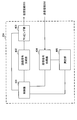
- FIG. 12 is a diagram showing an example of the entire configuration of the radio base station according to the present embodiment.
- the radio base station 10 includes a plurality of transmitting and receiving antennas 101, an amplifier unit 102, a transmitting and receiving unit 103, a baseband signal processing unit 104, a call processing unit 105, and a transmission path interface 106.
- Each of the transmitting and receiving antenna 101, the amplifier unit 102, and the transmitting and receiving unit 103 may be configured to include one or more.
- the radio base station 10 may configure a “receiving device” in UL and may configure a “transmitting device” in DL.
- User data transmitted from the radio base station 10 to the user terminal 20 by downlink is input from the higher station apparatus 30 to the baseband signal processing unit 104 via the transmission path interface 106.
- the baseband signal processing unit 104 performs packet data convergence protocol (PDCP) layer processing, user data division / combination, RLC layer transmission processing such as RLC (Radio Link Control) retransmission control, and MAC (Medium Access) for user data.
- Control Retransmission control (for example, processing of HARQ (Hybrid Automatic Repeat reQuest)), scheduling, transmission format selection, channel coding, rate matching, scrambling, Inverse Fast Fourier Transform (IFFT) processing and precoding Transmission processing such as at least one of the processing is performed and transferred to the transmission / reception unit 103.
- HARQ Hybrid Automatic Repeat reQuest
- IFFT Inverse Fast Fourier Transform
- Transmission processing such as at least one of the processing is performed and transferred to the transmission / reception unit 103.
- transmission processing such as channel coding and / or inverse fast Fourier transform is performed and transferred to the transmission / reception unit 103.
- the transmission / reception unit 103 converts the baseband signal output from the baseband signal processing unit 104 for each antenna into a radio frequency band and transmits the baseband signal.
- the radio frequency signal frequency-converted by the transmitting and receiving unit 103 is amplified by the amplifier unit 102 and transmitted from the transmitting and receiving antenna 101.
- the transmitter / receiver, the transmitting / receiving circuit or the transmitting / receiving device described based on the common recognition in the technical field according to the present invention can be constituted.
- the transmitting and receiving unit 103 may be configured as an integrated transmitting and receiving unit, or may be configured from a transmitting unit and a receiving unit.
- the radio frequency signal received by the transmitting and receiving antenna 101 is amplified by the amplifier unit 102.
- the transmitting and receiving unit 103 receives the UL signal amplified by the amplifier unit 102.
- the transmission / reception unit 103 frequency-converts the received signal into a baseband signal and outputs the result to the baseband signal processing unit 104.
- the baseband signal processing unit 104 performs Fast Fourier Transform (FFT) processing, Inverse Discrete Fourier Transform (IDFT) processing, and error correction on UL data included in the input UL signal. Decoding, reception processing of MAC retransmission control, and reception processing of RLC layer and PDCP layer are performed, and are transferred to the higher station apparatus 30 via the transmission path interface 106.
- the call processing unit 105 performs at least one of setting of a communication channel, call processing such as release, status management of the radio base station 10, and management of radio resources.
- the transmission path interface 106 transmits and receives signals to and from the higher station apparatus 30 via a predetermined interface. Also, the transmission path interface 106 transmits / receives signals (backhaul signaling) to / from the adjacent wireless base station 10 via an inter-base station interface (for example, an optical fiber conforming to CPRI (Common Public Radio Interface), X2 interface). It is also good.
- an inter-base station interface for example, an optical fiber conforming to CPRI (Common Public Radio Interface), X2 interface.
- the transmission / reception unit 103 may be a DL signal (for example, at least one of a DL control signal (also referred to as DL control channel or DCI), a DL data signal (also referred to as DL data channel or DL data), and a reference signal)
- a DL control signal also referred to as DL control channel or DCI
- a DL data signal also referred to as DL data channel or DL data
- a reference signal Send
- the transmission / reception unit 103 may be a UL signal (for example, at least one of a UL control signal (also referred to as UL control channel or UCI), a UL data signal (also referred to as UL data channel or UL data), and a reference signal)
- the transmission / reception unit 103 may transmit upper layer control information (for example, control information by MAC CE and / or RRC signaling).
- upper layer control information for example, control information by MAC CE and / or RRC signaling.
- the transmitting / receiving unit 103 uses TDL (time division multiple overlapping signals) using a DL / UL frequency band pair (DL / UL BWP pair) having a UL frequency band and a DL frequency band set in the frequency direction in the carrier. Signals and / or information may be transmitted and received.
- TDL time division multiple overlapping signals
- DL / UL frequency band pair DL / UL BWP pair
- Signals and / or information may be transmitted and received.
- FIG. 13 is a diagram showing an example of a functional configuration of the radio base station according to the present embodiment. Note that FIG. 13 mainly shows the functional blocks of the characterizing portion in the present embodiment, and the wireless base station 10 also has other functional blocks necessary for wireless communication.
- the baseband signal processing unit 104 includes a control unit 301, a transmission signal generation unit 302, a mapping unit 303, a reception signal processing unit 304, and a measurement unit 305.
- the control unit 301 controls the entire wireless base station 10.
- the control unit 301 may, for example, generate a DL signal by the transmission signal generation unit 302, map the DL signal by the mapping unit 303, receive processing (for example, demodulation) of the UL signal by the reception signal processing unit 304, and measure it by the measurement unit 305.
- Control at least one of Also, the control unit 301 may control scheduling of data channels (including DL data channels and / or UL data channels).
- the control unit 301 may control the transmission direction for each symbol in a time unit (for example, slot) which is a scheduling unit of the DL data channel. Specifically, the control unit 301 may control generation and / or transmission of slot format related information (SFI) indicating DL symbols and / or UL symbols in the slot.
- SFI slot format related information
- control unit 301 configures one or more BWPs, and uses TDP (time division duplex) or FDD (frequency division duplex) with the user terminal 20 using the set BWPs. You may control to perform line communication.
- TDP time division duplex
- FDD frequency division duplex
- the control unit 301 may set, for example, a plurality of DL / UL BWP pairs illustrated in FIGS. 4 to 10, switch these, and perform wireless communication with the user terminal 20.
- the control unit 301 can be configured of a controller, a control circuit, or a control device described based on the common recognition in the technical field according to the present invention.
- the transmission signal generation unit 302 generates a DL signal (including at least one of DL data (channel), DCI, DL reference signal, and control information by upper layer signaling) based on an instruction from the control unit 301, It may be output to the mapping unit 303.
- the transmission signal generation unit 302 can be a signal generator, a signal generation circuit or a signal generation device described based on the common recognition in the technical field according to the present invention.
- the mapping unit 303 maps the DL signal generated by the transmission signal generation unit 302 on a predetermined radio resource based on an instruction from the control unit 301, and outputs the DL signal to the transmission / reception unit 103.
- the mapping unit 303 maps the reference signal to a predetermined radio resource using the arrangement pattern determined by the control unit 301.
- the mapping unit 303 may be a mapper, a mapping circuit or a mapping device described based on the common recognition in the technical field according to the present invention.
- the reception signal processing unit 304 performs reception processing (for example, at least one of demapping, demodulation, and decoding) of the UL signal transmitted from the user terminal 20. Specifically, the reception signal processing unit 304 may output the reception signal and / or the signal after reception processing to the measurement unit 305.
- reception processing for example, at least one of demapping, demodulation, and decoding
- the received signal processing unit 304 can be configured from a signal processor, a signal processing circuit or a signal processing device described based on the common recognition in the technical field according to the present invention. Also, the received signal processing unit 304 can constitute a receiving unit according to the present invention.
- the measurement unit 305 measures the channel quality of UL based on, for example, received power of a reference signal (for example, reference signal received power (RSRP)) and / or received quality (for example, reference signal received quality (RSRQ)). May be The measurement result may be output to the control unit 301.
- a reference signal for example, reference signal received power (RSRP)
- RSSQ reference signal received quality
- FIG. 14 is a diagram showing an example of the entire configuration of the user terminal according to the present embodiment.
- the user terminal 20 includes a plurality of transmission / reception antennas 201 for MIMO transmission, an amplifier unit 202, a transmission / reception unit 203, a baseband signal processing unit 204, and an application unit 205.
- the user terminal 20 may configure a “transmitting device” in UL and may configure a “receiving device” in DL.
- the radio frequency signals received by the plurality of transmitting and receiving antennas 201 are amplified by the amplifier unit 202, respectively.
- Each transmission / reception unit 203 receives the DL signal amplified by the amplifier unit 202.
- the transmission / reception unit 203 frequency-converts the received signal into a baseband signal and outputs the result to the baseband signal processing unit 204.
- the baseband signal processing unit 204 performs at least one of FFT processing, error correction decoding, reception processing of retransmission control, and the like on the input baseband signal.
- the DL data is transferred to the application unit 205.
- the application unit 205 performs processing on a layer higher than the physical layer and the MAC layer.
- UL data is input from the application unit 205 to the baseband signal processing unit 204.
- the baseband signal processing unit 204 performs at least one of retransmission control processing (for example, processing of HARQ), channel coding, rate matching, puncturing, discrete Fourier transform (DFT) processing, IFFT processing, and the like.
- the data is transferred to each transmission / reception unit 203.
- UCI eg, A / N of DL signal, channel state information (CSI), scheduling request (SR), etc.
- CSI channel state information
- SR scheduling request
- the transmission / reception unit 203 converts the baseband signal output from the baseband signal processing unit 204 into a radio frequency band and transmits it.
- the radio frequency signal frequency-converted by the transmitting and receiving unit 203 is amplified by the amplifier unit 202 and transmitted from the transmitting and receiving antenna 201.
- the transmitting / receiving unit 203 is a DL signal (for example, at least one of a DL control signal (also referred to as DL control channel or DCI), a DL data signal (also referred to as DL data channel or DL data), and a reference signal) Receive
- the transmission / reception unit 203 is a UL signal (for example, at least one of a UL control signal (also referred to as a UL control channel or UCI), a UL data signal (also referred to as a UL data channel or UL data), and a reference signal)
- a DL control signal also referred to as DL control channel or DCI
- a DL data signal also referred to as DL data channel or DL data
- a reference signal for example, at least one of a UL control signal (also referred to as a UL control channel or UCI), a UL data signal (also referred to as a UL data channel or UL data), and a reference signal)
- the transmitting / receiving unit 203 may receive upper layer control information (for example, control information by MAC CE and / or RRC signaling).
- upper layer control information for example, control information by MAC CE and / or RRC signaling.
- the transmission / reception unit 203 uses TDL (time division multiple overlapping signals) using a DL / UL frequency band pair (DL / UL BWP pair) having a UL frequency band and a DL frequency band set in the frequency direction in the carrier. May transmit and receive signals and / or information.
- TDL time division multiple overlapping signals
- the transmission / reception unit 203 can be a transmitter / receiver, a transmission / reception circuit or a transmission / reception device described based on the common recognition in the technical field according to the present invention.
- the transmission / reception unit 203 may be configured as an integrated transmission / reception unit, or may be configured from a transmission unit and a reception unit.
- FIG. 15 is a diagram showing an example of a functional configuration of a user terminal according to the present embodiment.
- the functional blocks of the characteristic part in the present embodiment are mainly shown, and the user terminal 20 also has other functional blocks necessary for wireless communication.
- the baseband signal processing unit 204 included in the user terminal 20 includes the control unit 401, the transmission signal generation unit 402, the mapping unit 403, the reception signal processing unit 404, and the measurement unit 405. Have.
- the control unit 401 controls the entire user terminal 20.
- the control unit 401 controls, for example, at least one of UL signal generation by the transmission signal generation unit 402, mapping of the UL signal by the mapping unit 403, reception processing of the DL signal by the reception signal processing unit 404, and measurement by the measurement unit 405. Do.
- control unit 401 uses a plurality of DL / UL frequency band pairs having a UL frequency band and a DL frequency band set in the frequency direction in the carrier, and transmits signals in TDD (time division multiple overlap). And / or control information to be transmitted and received.
- TDD time division multiple overlap
- a first DL / UL frequency band pair sharing a center frequency between the UL frequency band and the DL frequency band and being biased toward the upper limit frequency side or the lower limit frequency side in the frequency band of the carrier
- the bandwidth of at least one of the UL frequency band and the DL frequency band is wider than the bandwidth of the first DL / UL frequency band pair, and the at least one frequency band is the first DL / UL frequency band
- the second DL / UL frequency band pair including the frequency band of the pair is switched to control to perform the transmission and reception.
- the center frequency may be different between the UL frequency band and the DL frequency band, and one frequency band may be included in the other frequency band.
- the transmission / reception unit 203 and / or the reception signal processing unit 404 is a frequency band defined by the wider one of the UL frequency band and the DL frequency band in the second frequency band pair. Outside transmission and reception may not be performed.
- control unit 401 assigns uplink control information in the UL frequency band of the first frequency band pair and in the UL frequency band of the second frequency band pair and the frequency resource assigned to the uplink control information. Shared frequency resources.
- the transmission / reception unit 203 and / or the reception signal processing unit 404 is defined based on the wider one of the UL frequency band and the DL frequency band in the second frequency band pair. Downlink control information of a size may be received.
- the control unit 401 may perform control to perform wireless communication in TDD using a plurality of DL / UL BWP pairs defined in the above-described first to fourth aspects and the modification.
- the control unit 401 can be configured of a controller, a control circuit, or a control device described based on the common recognition in the technical field according to the present invention.
- Transmission signal generation unit 402 generates retransmission control information of UL signal and DL signal (for example, coding, rate matching, puncturing, modulation, etc.) based on an instruction from control unit 401, and outputs the result to mapping unit 403. Do.
- the transmission signal generation unit 402 can be a signal generator, a signal generation circuit, or a signal generation device described based on the common recognition in the technical field according to the present invention.
- the mapping unit 403 may be a mapper, a mapping circuit or a mapping device described based on the common recognition in the technical field according to the present invention.
- the reception signal processing unit 404 performs reception processing (for example, at least one of demapping, demodulation, and decoding) of the DL signal.
- reception processing for example, at least one of demapping, demodulation, and decoding
- the reception signal processing unit 404 may demodulate the DL data channel using the reference signal of the arrangement pattern determined by the control unit 401.
- the reception signal processing unit 404 may output the reception signal and / or the signal after reception processing to the control unit 401 and / or the measurement unit 405.
- the reception signal processing unit 404 outputs, for example, upper layer control information by upper layer signaling, L1 / L2 control information (for example, UL grant and / or DL assignment), and the like to the control unit 401.
- the received signal processing unit 404 can be composed of a signal processor, a signal processing circuit or a signal processing device described based on the common recognition in the technical field according to the present invention. Also, the received signal processing unit 404 can constitute a receiving unit according to the present invention.
- Measuring section 405 measures a channel state based on a reference signal (for example, CSI-RS) from radio base station 10, and outputs the measurement result to control section 401.
- the channel state measurement may be performed for each CC.
- the measuring unit 405 can be configured of a signal processor, a signal processing circuit or a signal processing device, and a measuring instrument, a measuring circuit or a measuring device described based on the common recognition in the technical field according to the present invention.
- each functional block is realized by one physically and / or logically coupled device, or directly and / or indirectly two or more physically and / or logically separated devices. It may be connected by (for example, wired and / or wireless) and realized by the plurality of devices.
- the wireless base station, the user terminal, and the like in the present embodiment may function as a computer that performs the process of the wireless communication method of the present invention.
- FIG. 16 is a diagram showing an example of the hardware configuration of the radio base station and the user terminal according to the present embodiment.
- the above-described wireless base station 10 and user terminal 20 may be physically configured as a computer device including a processor 1001, a memory 1002, a storage 1003, a communication device 1004, an input device 1005, an output device 1006, a bus 1007 and the like. Good.
- the term “device” can be read as a circuit, a device, a unit, or the like.
- the hardware configuration of the radio base station 10 and the user terminal 20 may be configured to include one or more of the devices illustrated in the figure, or may be configured without including some devices.
- processor 1001 may be implemented by one or more chips.
- Each function in the radio base station 10 and the user terminal 20 is performed, for example, by causing a processor 1001 to read predetermined software (program) on hardware such as the processor 1001 and the memory 1002, and the processor 1001 performs an operation. This is realized by controlling at least one of reading and writing of data in the memory 1002 and the storage 1003.
- the processor 1001 operates, for example, an operating system to control the entire computer.
- the processor 1001 may be configured by a central processing unit (CPU: Central Processing Unit) including an interface with a peripheral device, a control device, an arithmetic device, a register, and the like.
- CPU Central Processing Unit
- the above-described baseband signal processing unit 104 (204), call processing unit 105, and the like may be realized by the processor 1001.
- the processor 1001 reads a program (program code), a software module, data, and the like from the storage 1003 and / or the communication device 1004 to the memory 1002, and executes various processing according to these.
- a program a program that causes a computer to execute at least a part of the operations described in the above embodiments is used.
- the control unit 401 of the user terminal 20 may be realized by a control program stored in the memory 1002 and operated by the processor 1001, or may be realized similarly for other functional blocks.
- the memory 1002 is a computer readable recording medium, and for example, at least at least a read only memory (ROM), an erasable programmable ROM (EPROM), an electrically EPROM (EEPROM), a random access memory (RAM), or any other suitable storage medium. It may consist of one.
- the memory 1002 may be called a register, a cache, a main memory (main storage device) or the like.
- the memory 1002 may store a program (program code), a software module, and the like that can be executed to implement the wireless communication method according to an embodiment of the present invention.
- the storage 1003 is a computer readable recording medium, and for example, a flexible disk, a floppy (registered trademark) disk, a magneto-optical disk (for example, a compact disk (CD-ROM (Compact Disc ROM), etc.), a digital versatile disk, Blu-ray® disc), removable disc, hard disc drive, smart card, flash memory device (eg card, stick, key drive), magnetic stripe, database, server, at least one other suitable storage medium May be composed of
- the storage 1003 may be called an auxiliary storage device.
- the communication device 1004 is hardware (transmission / reception device) for performing communication between computers via a wired and / or wireless network, and is also called, for example, a network device, a network controller, a network card, a communication module, or the like.
- the communication device 1004 includes, for example, a high frequency switch, a duplexer, a filter, a frequency synthesizer, and the like to realize, for example, frequency division duplex (FDD) and / or time division duplex (TDD). It may be configured.
- FDD frequency division duplex
- TDD time division duplex
- the transmission / reception antenna 101 (201), the amplifier unit 102 (202), the transmission / reception unit 103 (203), the transmission path interface 106, and the like described above may be realized by the communication device 1004.
- the input device 1005 is an input device (for example, a keyboard, a mouse, a microphone, a switch, a button, a sensor, and the like) that receives an input from the outside.
- the output device 1006 is an output device (for example, a display, a speaker, a light emitting diode (LED) lamp, and the like) that performs output to the outside.
- the input device 1005 and the output device 1006 may be integrated (for example, a touch panel).
- each device shown in FIG. 16 is connected by a bus 1007 for communicating information.
- the bus 1007 may be configured by a single bus or may be configured by different buses among the devices.
- radio base station 10 and the user terminal 20 may be microprocessors, digital signal processors (DSPs), application specific integrated circuits (ASICs), programmable logic devices (PLDs), field programmable gate arrays (FPGAs), etc. It may be configured to include hardware, and part or all of each functional block may be realized by the hardware. For example, processor 1001 may be implemented in at least one of these hardware.
- DSPs digital signal processors
- ASICs application specific integrated circuits
- PLDs programmable logic devices
- FPGAs field programmable gate arrays
- the channels and / or symbols may be signaling.
- the signal may be a message.
- the reference signal may be abbreviated as RS (Reference Signal), and may be referred to as a pilot (Pilot), a pilot signal or the like according to an applied standard.
- a component carrier CC: Component Carrier
- CC Component Carrier
- a radio frame may be configured with one or more periods (frames) in the time domain.
- Each of the one or more periods (frames) that constitute a radio frame may be referred to as a subframe.
- a subframe may be configured with one or more slots in the time domain.
- the subframes may be of a fixed time length (e.g., 1 ms) independent of the neurology.
- a slot may be configured with one or more symbols (such as orthogonal frequency division multiplexing (OFDM) symbols, single carrier frequency division multiple access (SC-FDMA) symbols, etc.) in the time domain.
- the slot may be a time unit based on the neurology.
- the slot may include a plurality of minislots. Each minislot may be comprised of one or more symbols in the time domain.
- a radio frame, a subframe, a slot, a minislot and a symbol all represent time units when transmitting a signal.
- subframes, slots, minislots and symbols other names corresponding to each may be used.
- one subframe may be referred to as a transmission time interval (TTI)
- TTI transmission time interval
- a plurality of consecutive subframes may be referred to as a TTI
- one slot or one minislot may be referred to as a TTI.
- TTI transmission time interval
- the subframe and / or TTI may be a subframe (1 ms) in existing LTE, a period shorter than 1 ms (eg, 1-13 symbols), or a period longer than 1 ms. It may be.
- TTI refers to, for example, the minimum time unit of scheduling in wireless communication.
- the radio base station performs scheduling to allocate radio resources (such as frequency bandwidth and / or transmission power that can be used in each user terminal) to each user terminal on a TTI basis.
- the TTI may be a transmission time unit of a channel coded data packet (transport block) or may be a processing unit such as scheduling and / or link adaptation. If one slot or one minislot is referred to as TTI, one or more TTIs (ie, one or more slots or one or more minislots) may be the minimum time unit of scheduling. In addition, the number of slots (the number of minislots) constituting the minimum time unit of the scheduling may be controlled.
- a TTI having a time length of 1 ms may be referred to as a normal TTI (TTI in LTE Rel. 8-12), a normal TTI, a long TTI, a normal subframe, a normal subframe, a long subframe, or the like.
- a TTI shorter than a normal TTI may be referred to as a short TTI, a short TTI, a partial TTI (partial or fractional TTI), a short subframe, a short subframe, or the like.
- a resource block is a resource allocation unit in time domain and frequency domain, and may include one or more consecutive subcarriers (subcarriers) in the frequency domain. Also, an RB may include one or more symbols in the time domain, and may be one slot, one minislot, one subframe, or one TTI in length. One TTI and one subframe may be configured of one or more resource blocks, respectively.
- the RB may be called a physical resource block (PRB: Physical RB), a PRB pair, an RB pair, or the like.
- a resource block may be composed of one or more resource elements (RE: Resource Element).
- RE Resource Element
- one RE may be one subcarrier and one symbol radio resource region.
- the above-described structures such as the radio frame, subframe, slot, minislot and symbol are merely examples.
- the number of subframes included in a radio frame the number of slots per subframe or radio frame, the number of minislots included in a slot, the number of symbols included in a slot or minislot, and subcarriers included in an RB
- the number of symbols in TTI, symbol length, cyclic prefix (CP) length, and other configurations may be variously changed.
- the information, parameters, and the like described in the present specification may be represented by absolute values, may be represented by relative values from predetermined values, or may be represented by corresponding other information.
- the radio resources may be indicated by a predetermined index.
- the formulas etc. that use these parameters may differ from those explicitly disclosed herein.
- data, instructions, commands, information, signals, bits, symbols, chips etc may be voltage, current, electromagnetic waves, magnetic fields or particles, optical fields or photons, or any of these May be represented by a combination of
- information, signals, etc. may be output from the upper layer to the lower layer and / or from the lower layer to the upper layer.
- Information, signals, etc. may be input / output via a plurality of network nodes.
- the input / output information, signals and the like may be stored in a specific place (for example, a memory) or may be managed by a management table. Information, signals, etc. input and output can be overwritten, updated or added. The output information, signals and the like may be deleted. The input information, signals and the like may be transmitted to other devices.
- notification of information is not limited to the aspects / embodiments described herein, and may be performed in other manners.
- notification of information may be physical layer signaling (eg, downlink control information (DCI), uplink control information (UCI)), upper layer signaling (eg, RRC (Radio Resource Control) signaling, It may be implemented by broadcast information (Master Information Block (MIB), System Information Block (SIB), etc.), MAC (Medium Access Control) signaling, other signals, or a combination thereof.
- DCI downlink control information
- UCI uplink control information
- RRC Radio Resource Control
- MIB Master Information Block
- SIB System Information Block
- MAC Medium Access Control
- the physical layer signaling may be called L1 / L2 (Layer 1 / Layer 2) control information (L1 / L2 control signal), L1 control information (L1 control signal), or the like.
- RRC signaling may be referred to as an RRC message, and may be, for example, an RRC connection setup (RRC Connection Setup) message, an RRC connection reconfiguration (RRC Connection Reconfiguration) message, or the like.
- MAC signaling may be notified by, for example, a MAC control element (MAC CE (Control Element)).
- notification of predetermined information is not limited to what is explicitly performed, but implicitly (for example, by not notifying the predetermined information or another It may be performed by notification of information.
- the determination may be performed by a value (0 or 1) represented by one bit, or may be performed by a boolean value represented by true or false. , Numerical comparison (for example, comparison with a predetermined value) may be performed.
- Software may be called software, firmware, middleware, microcode, hardware description language, or any other name, and may be instructions, instruction sets, codes, code segments, program codes, programs, subprograms, software modules. Should be interpreted broadly to mean applications, software applications, software packages, routines, subroutines, objects, executables, threads of execution, procedures, functions, etc.
- software, instructions, information, etc. may be sent and received via a transmission medium.
- software may use a wired technology (coaxial cable, fiber optic cable, twisted pair, digital subscriber line (DSL), etc.) and / or a wireless technology (infrared, microwave, etc.), a website, a server
- wired technology coaxial cable, fiber optic cable, twisted pair, digital subscriber line (DSL), etc.
- wireless technology infrared, microwave, etc.
- system and "network” as used herein are used interchangeably.
- base station Base Station
- radio base station eNB
- gNB gNodeB
- cell cell
- cell group cell group
- carrier carrier
- component carrier component carrier
- a base station may also be called in terms of a fixed station (Node station), NodeB, eNodeB (eNB), access point (access point), transmission point, reception point, femtocell, small cell, and so on.
- a base station may accommodate one or more (e.g., three) cells (also called sectors). If the base station accommodates multiple cells, the entire coverage area of the base station can be partitioned into multiple smaller areas, each smaller area being a base station subsystem (eg, a small base station for indoor use (RRH: Communication service can also be provided by Remote Radio Head).
- RRH Communication service can also be provided by Remote Radio Head.
- the terms "cell” or “sector” refer to part or all of the coverage area of a base station and / or a base station subsystem serving communication services in this coverage.
- MS mobile station
- UE user equipment
- a base station may also be called in terms of a fixed station (Node station), NodeB, eNodeB (eNB), access point (access point), transmission point, reception point, femtocell, small cell, and so on.
- Node station Node station
- NodeB NodeB
- eNodeB eNodeB
- access point access point
- transmission point reception point
- femtocell small cell, and so on.
- the mobile station may be a subscriber station, a mobile unit, a subscriber unit, a wireless unit, a remote unit, a mobile device, a wireless device, a wireless communication device, a remote device, a mobile subscriber station, an access terminal, a mobile terminal, a wireless terminal, by those skilled in the art. It may also be called a terminal, a remote terminal, a handset, a user agent, a mobile client, a client or some other suitable term.
- the radio base station in the present specification may be replaced with a user terminal.
- each aspect / embodiment of the present invention may be applied to a configuration in which communication between a wireless base station and a user terminal is replaced with communication between a plurality of user terminals (D2D: Device-to-Device).
- the user terminal 20 may have a function that the above-described radio base station 10 has.
- “up” and / or “down” may be read as “side”.
- the upstream channel may be read as a side channel.
- a user terminal herein may be read at a radio base station.
- the radio base station 10 may have a function that the above-described user terminal 20 has.
- the specific operation to be performed by the base station may be performed by the upper node in some cases.
- various operations performed for communication with a terminal may be performed by the base station, one or more network nodes other than the base station (for example, it is apparent that it can be performed by MME (Mobility Management Entity), S-GW (Serving-Gateway), etc. but not limited thereto or a combination thereof.
- MME Mobility Management Entity
- S-GW Serving-Gateway
- Each aspect / embodiment described in the present specification includes LTE (Long Term Evolution), LTE-A (LTE-Advanced), LTE-B (LTE-Beyond), SUPER 3G, IMT-Advanced, 4G (4th generation mobile) Communication system), 5G (5th generation mobile communication system), FRA (Future Radio Access), New-RAT (Radio Access Technology), NR (New Radio), NX (New radio access), FX (Future generation radio access), GSM (registered trademark) (Global System for Mobile communications), CDMA2000, UMB (Ultra Mobile Broadband), IEEE 802.11 (Wi-Fi (registered trademark)), IEEE 802.16 (WiMAX (registered trademark)), IEEE 802 .20, UWB (Ultra-Wide Band), Bluetooth (registered trademark),
- the present invention may be applied to a system utilizing another appropriate wireless communication method of and / or an extended next generation system based on these.
- the phrase “based on” does not mean “based only on,” unless expressly stated otherwise. In other words, the phrase “based on” means both “based only on” and “based at least on.”
- any reference to an element using the designation "first,” “second,” etc. as used herein does not generally limit the quantity or order of those elements. These designations may be used herein as a convenient way of distinguishing between two or more elements. Thus, reference to the first and second elements does not mean that only two elements can be taken or that the first element must somehow precede the second element.
- determining may encompass a wide variety of operations. For example, “determination” may be calculating, computing, processing, deriving, investigating, looking up (eg, table, database or other data) A search on structure), ascertaining, etc. may be considered as “determining”. Also, “determination” may be receiving (e.g. receiving information), transmitting (e.g. transmitting information), input (input), output (output), access (access) It may be considered as “determining” (eg, accessing data in memory) and the like. Also, “determination” is considered to be “determination” to resolve, select, choose, choose, establish, compare, etc. It is also good. That is, “determination” may be considered as “determining” some action.
- the terms “connected”, “coupled”, or any variation thereof are any direct or indirect connection between two or more elements or It means a bond and can include the presence of one or more intermediate elements between two elements “connected” or “connected” to each other.
- the coupling or connection between elements may be physical, logical or a combination thereof.
- the two elements are by using one or more wires, cables and / or printed electrical connections, and radio frequency as some non-limiting and non-exclusive examples. It can be considered “connected” or “coupled” to one another by using electromagnetic energy such as electromagnetic energy having wavelengths in the region, microwave region and light (both visible and invisible) regions.
Abstract
The present invention appropriately carries out TDD wireless communication by using a DL/UL frequency band pair having a DL frequency and a UL frequency band configured in a frequency direction in a carrier. This user terminal is provided with: a transmission/reception unit that carries out transmission/reception through Time Division Duplex (TDD) by using the DL/UL frequency band pair having the DL frequency band and the UL frequency band configured in the frequency direction in the carrier; and a control unit that executes control so as to carry out the transmission/reception by switching between, in the frequency band of the carrier, a first DL/UL frequency band pair in which the center frequency is shared between the UL frequency band and the DL frequency band and which is configured so as to be biased to the upper-limit frequency side or the lower-limit frequency side, and a second DL/UL frequency band pair in which the band width of at least one of the UL frequency band and the DL frequency band is larger than the band width of the first DL/UL frequency band pair, and in which at least one of the frequency bands includes the frequency band of the first DL/UL frequency band pair.
Description
本発明は、次世代移動通信システムにおけるユーザ端末及び無線通信方法に関する。
The present invention relates to a user terminal and a wireless communication method in a next-generation mobile communication system.
UMTS(Universal Mobile Telecommunications System)ネットワークにおいて、さらなる高速データレート、低遅延などを目的としてロングタームエボリューション(LTE:Long Term Evolution)が仕様化された(非特許文献1)。また、LTEからの更なる広帯域化及び高速化を目的として、LTEの後継システム(例えば、LTE-A(LTE-Advanced)、FRA(Future Radio Access)、4G、5G、5G+(plus)、NR(New RAT)、LTE Rel.14、15~、などともいう)も検討されている。
In Universal Mobile Telecommunications System (UMTS) networks, Long Term Evolution (LTE) has been specified for the purpose of further higher data rates, lower delays, etc. (Non-Patent Document 1). Also, for the purpose of achieving wider bandwidth and higher speed from LTE, successor systems of LTE (for example, LTE-A (LTE-Advanced), FRA (Future Radio Access), 4G, 5G, 5G + (plus), NR ( Also referred to as New RAT), LTE Rel. 14, 15 and so on.
また、既存のLTEシステム(例えば、LTE Rel.8-13)では、1msのサブフレームをスケジューリング単位として、下りリンク(DL:Downlink)及び/又は上りリンク(UL:Uplink)の通信が行われる。当該サブフレームは、例えば、通常サイクリックプリフィクス(NCP:Normal Cyclic Prefix)の場合、サブキャリア間隔15kHzの14シンボルで構成される。当該サブフレームは、伝送時間間隔(TTI:Transmission Time Interval)等とも呼ばれる。
Also, in the existing LTE system (for example, LTE Rel. 8-13), downlink (DL: Downlink) and / or uplink (UL: Uplink) communication is performed with a subframe of 1 ms as a scheduling unit. For example, in the case of Normal Cyclic Prefix (NCP), the subframe is composed of 14 symbols of 15 kHz subcarrier spacing. The subframes are also referred to as transmission time intervals (TTIs) or the like.
また、ユーザ端末(UE:User Equipment)は、無線基地局(例えば、eNB:eNodeB)からの下りリンク制御情報(DCI:Downlink Control Information)(DLアサインメント等ともいう)に基づいて、DLデータチャネル(例えば、PDSCH:Physical Downlink Shared Channel、DL共有チャネル等ともいう)の受信を制御する。また、ユーザ端末は、無線基地局からのDCI(ULグラント等ともいう)に基づいて、ULデータチャネル(例えば、PUSCH:Physical Uplink Shared Channel、UL共有チャネル等ともいう)の送信を制御する。
Also, the user terminal (UE: User Equipment) is a DL data channel based on downlink control information (DCI: Downlink Control Information) (also referred to as DL assignment etc.) from a radio base station (for example, eNB: eNodeB). It controls reception of (for example, PDSCH: Physical Downlink Shared Channel, DL Shared Channel, etc.). Also, the user terminal controls transmission of a UL data channel (for example, PUSCH: also referred to as Physical Uplink Shared Channel, UL shared channel, etc.) based on DCI (also referred to as UL grant, etc.) from the radio base station.
将来の無線通信システム(例えば、NR)では、ユーザ端末は、DL制御チャネル(例えば、PDCCH:Physical Downlink Control Channel)が割り当てられる候補領域である制御リソース領域(例えば、制御リソースセット(CORESET:control resource set))を監視(ブラインド復号)して、DCIを受信(検出)することが検討されている。
In the future wireless communication system (for example, NR), a user terminal is a control resource area (for example, control resource set (CORESET: control resource) which is a candidate area to which a DL control channel (for example, PDCCH: Physical Downlink Control Channel) is allocated. It is considered to receive (detect) DCI by monitoring (blind decoding)).
また、当該将来の無線通信システムにおいては、キャリア(コンポーネントキャリア(CC:Component Carrier)又はシステム帯域等ともいう)内の一以上の部分的な(partial)周波数帯域(部分帯域(Partial Band)、帯域幅部分(BWP:Bandwidth part)等ともいう)を、DL及び/又はUL通信(DL/UL通信)に用いることが検討されている。
Also, in the future wireless communication system, one or more partial frequency bands (Partial Band), bands within a carrier (also referred to as component carrier (CC) or system band etc.) It has been considered to use a width part (BWP: Bandwidth part, etc.) for DL and / or UL communication (DL / UL communication).
このように、キャリア内にDL/UL通信に用いられる一以上の周波数帯域(例えば、BWP)を設定可能とする場合、当該周波数帯域のアクティブ化(activation)及び/又は非アクティブ化(deactivation)(アクティブ化/非アクティブ化)が行われると考えられる。
Thus, when one or more frequency bands (for example, BWP) used for DL / UL communication can be set in the carrier, activation and / or deactivation (frequency activation) of the frequency band can be performed. It is considered that activation / deactivation is performed.
さらに、一以上のBWPが設定(configure)され、このBWPを用いて、TDD(時分割複信)又はFDD(周波数分割複信)で無線通信が行われることが考えられる。例えば、TDDが行われる場合には、1つのBWP内にUL BWP(UL用周波数帯域)とDL BWP(DL用周波数帯域)とが設定され、DL/UL周波数帯域ペア(DL/UL BWPペア)が規定される。このようなDL/UL BWPペアを用いて、適切にTDDの無線通信を行うことが望まれる。
Furthermore, it is conceivable that one or more BWPs are configured and wireless communication is performed by TDD (time division duplex) or FDD (frequency division duplex) using this BWP. For example, when TDD is performed, UL BWP (frequency band for UL) and DL BWP (frequency band for DL) are set in one BWP, and DL / UL frequency band pair (DL / UL BWP pair) Is defined. It is desirable to appropriately perform TDD wireless communication using such a DL / UL BWP pair.
本発明はかかる点に鑑みてなされたものであり、キャリア内で周波数方向に設定されたUL用周波数帯域及びDL用周波数を有するDL/UL周波数帯域ペア(DL/UL BWPペア)を用いて、TDDの無線通信を適切に行うユーザ端末及び無線通信方法を提供することを目的の一つとする。
The present invention has been made in view of the foregoing points, and uses a DL / UL frequency band pair (DL / UL BWP pair) having a UL frequency band and a DL frequency set in the frequency direction in a carrier. An object of the present invention is to provide a user terminal and a wireless communication method that appropriately perform TDD wireless communication.
ユーザ端末の一態様は、キャリア内で周波数方向に設定されたUL用周波数帯域及びDL用周波数帯域を有するDL/UL周波数帯域ペア用いて、TDD(時分割多重複信)で送受信を行う送受信部と、UL用周波数帯域とDL用周波数帯域とで中心周波数を共有し、上記キャリアの周波数帯域において、上限周波数側又は下限周波数側に偏って設定されている第1のDL/UL周波数帯域ペアと、UL用周波数帯域及びDL用周波数帯域の少なくとも一方の帯域幅が上記第1のDL/UL周波数帯域ペアの帯域幅よりも広く、上記少なくとも一方の周波数帯域が上記第1のDL/UL周波数帯域ペアの周波数帯域を含む、第2のDL/UL周波数帯域ペアと、を切り替えて上記送受信が行われるように制御する制御部と、を備える。
One aspect of a user terminal is a transmitting / receiving unit that performs transmission / reception in TDD (Time Division Multiplexing) using a DL / UL frequency band pair having a UL frequency band and a DL frequency band set in a frequency direction in a carrier And a first DL / UL frequency band pair which shares a center frequency between the UL frequency band and the DL frequency band and is biased toward the upper limit frequency side or the lower limit frequency side in the carrier frequency band The bandwidth of at least one of the UL frequency band and the DL frequency band is wider than the bandwidth of the first DL / UL frequency band pair, and the at least one frequency band is the first DL / UL frequency band And a control unit configured to switch between a second DL / UL frequency band pair including a pair of frequency bands and control the transmission and reception to be performed.
本発明によれば、キャリア内で周波数方向に部分的に設定されたUL用周波数帯域及びDL用周波数を有するDL/UL周波数帯域ペア(DL/UL BWPペア)を用いて、TDDの無線通信を適切に行うことができる。
According to the present invention, TDD wireless communication is performed using a DL / UL frequency band pair (DL / UL BWP pair) having UL frequency bands and DL frequencies partially set in the frequency direction in a carrier. It can be done properly.
将来の無線通信システム(例えば、NR、5G又は5G+)では、既存のLTEシステム(例えば、LTE Rel.8-13)より広い帯域幅(例えば、100~800MHz)のキャリア(コンポーネントキャリア(CC:Component Carrier)、セル又はシステム帯域等ともいう)を割り当てることが検討されている。
In the future wireless communication systems (for example, NR, 5G or 5G +), carriers (component carriers (CC: Component Carrier) having a wider bandwidth (for example, 100 to 800 MHz) than existing LTE systems (for example, LTE Rel. 8-13) It is considered to assign a carrier (also referred to as a cell or a system band).
一方、当該将来の無線通信システムでは、当該キャリア全体で送信及び/又は受信(送受信)する能力(capability)を有するユーザ端末(Wideband(WB) UE、single carrier WB UE等ともいう)と、当該キャリア全体で送受信する能力を有しないユーザ端末(BW reduced UE等ともいう)とが混在することが想定される。
On the other hand, in the future wireless communication system, a user terminal (also referred to as Wideband (WB) UE, single carrier WB UE, etc.) capable of transmitting and / or receiving (transmitting / receiving) over the entire carrier and the carrier It is assumed that user terminals (also referred to as BW reduced UE etc.) that do not have the ability to transmit and receive as a whole coexist.
このように、将来の無線通信システムでは、サポートする帯域幅が異なる複数のユーザ端末が混在すること(various BW UE capabilities)が想定されるため、キャリア内に一以上の部分的な周波数帯域を準静的に設定(configure)することが検討されている。当該キャリア内の各周波数帯域(例えば、50MHz又は200MHzなど)は、部分帯域又は帯域幅部分(BWP:Bandwidth part)等と呼ばれる。
Thus, in the future wireless communication system, it is assumed that a plurality of user terminals with different supported bandwidths are mixed (various BW UE capabilities), so that one or more partial frequency bands in the carrier are allocated. It is considered to configure statically. Each frequency band (for example, 50 MHz or 200 MHz) in the carrier is called a sub-band or bandwidth part (BWP) or the like.
図1は、BWPの設定シナリオの一例を示す図である。図1Aでは、1キャリア内に1BWPがユーザ端末に設定されるシナリオ(Usage scenario#1)が示される。例えば、図1Aでは、800MHzのキャリア内に200MHzのBWPが設定される。当該BWPのアクティブ化(activation)又は非アクティブ化(deactivation)は制御されてもよい。
FIG. 1 is a diagram illustrating an example of a BWP setting scenario. FIG. 1A shows a scenario (Usage scenario # 1) in which one BWP is set as a user terminal in one carrier. For example, in FIG. 1A, a 200 MHz BWP is set in an 800 MHz carrier. The activation or deactivation of the BWP may be controlled.
ここで、BWPのアクティブ化とは、当該BWPを利用可能な状態である(又は当該利用可能な状態に遷移する)ことであり、BWPの設定情報(configuration)(BWP設定情報)のアクティブ化又は有効化等とも呼ばれる。また、BWPの非アクティブ化とは、当該BWPを利用不可能な状態である(又は当該利用不可能な状態に遷移する)ことであり、BWP設定情報の非アクティブ化又は無効化等とも呼ばれる。
Here, BWP activation means being in a usable state (or transitioning to the usable state), and activating BWP setting information (configuration) (BWP setting information) or It is also called validation. In addition, the deactivation of the BWP means that the BWP is in an unusable state (or transits to the unusable state), and is also called deactivation or invalidation of BWP setting information.
図1Bでは、1キャリア内に複数のBWPがユーザ端末に設定されるシナリオ(Usage scenario#2)が示される。図1Bに示すように、当該複数のBWP(例えば、BWP#1及び#2)の少なくとも一部は重複してもよい。例えば、図1Bでは、BWP#1は、BWP#2の一部の周波数帯域である。
FIG. 1B shows a scenario (Usage scenario # 2) in which a plurality of BWPs are set in a user terminal in one carrier. As shown in FIG. 1B, at least a portion of the plurality of BWPs (eg, BWPs # 1 and # 2) may overlap. For example, in FIG. 1B, BWP # 1 is a partial frequency band of BWP # 2.
また、当該複数のBWPの少なくとも一つのアクティブ化又は非アクティブ化が制御されてもよい。また、ある時間においてアクティブ化されるBWPの数は制限されてもよい(例えば、ある時間において1BWPだけがアクティブであってもよい)。例えば、図1Bでは、ある時間においてBWP#1又は#2のいずれか一方だけがアクティブである。
Also, at least one activation or deactivation of the plurality of BWPs may be controlled. Also, the number of BWPs activated at any given time may be limited (eg, only one BWP may be active at any given time). For example, in FIG. 1B, only one of BWP # 1 or # 2 is active at a certain time.
例えば、図1Bでは、データの送受信が行われない場合、BWP#1がアクティブ化され、データの送受信が行われる場合、BWP#2がアクティブ化されてもよい。具体的には、送受信されるデータが発生すると、BWP#1からBWP#2への切り替えが行われ、データの送受信が終了すると、BWP#2からBWP#1への切り替えが行われてもよい。これにより、ユーザ端末は、BWP#1よりも帯域幅の広いBWP#2を常に監視する必要がないので、消費電力を抑制できる。
For example, in FIG. 1B, BWP # 1 may be activated when data transmission / reception is not performed, and BWP # 2 may be activated when data transmission / reception is performed. Specifically, when data to be transmitted or received is generated, switching from BWP # 1 to BWP # 2 may be performed, and when data transmission / reception is completed, switching from BWP # 2 to BWP # 1 may be performed. . As a result, the user terminal does not have to constantly monitor BWP # 2, which has a wider bandwidth than BWP # 1, and can therefore reduce power consumption.
なお、図1A及び1Bにおいて、ネットワーク(例えば、無線基地局)は、ユーザ端末がアクティブ状態のBWP外で受信及び/又は送信することを想定しなくともよい。なお、図1Aにおいて、キャリア全体をサポートするユーザ端末が、当該BWP外で信号を受信及び/又は送信することは何ら抑制されない。
Note that, in FIGS. 1A and 1B, the network (for example, a radio base station) may not assume that the user terminal receives and / or transmits outside the BWP in the active state. In addition, in FIG. 1A, the user terminal supporting the entire carrier is not suppressed at all from receiving and / or transmitting a signal outside the BWP.
図1Cでは、1キャリア内の異なる帯域に複数のBWPが設定されるシナリオ(Usage scenario#3)が示される。図1Cに示すように、当該複数のBWPには異なるニューメロロジーが適用されてもよい。ここで、ニューメロロジーは、サブキャリア間隔、シンボル長、スロット長、サイクリックプレフィックス(CP)長、スロット(伝送時間間隔(TTI:Transmission Time Interval))長、スロットあたりのシンボル数などの少なくとも1つであってもよい。
FIG. 1C shows a scenario (Usage scenario # 3) in which a plurality of BWPs are set in different bands in one carrier. As shown in FIG. 1C, different numerologies may be applied to the plurality of BWPs. Here, the neurology includes at least one of subcarrier spacing, symbol length, slot length, cyclic prefix (CP) length, slot (transmission time interval (TTI)) length, number of symbols per slot, etc. It may be one.
例えば、図1Cでは、キャリア全体で送受信する能力を有するユーザ端末に対して、ニューメロロジーが異なるBWP#1及び#2が設定される。図1Cでは、ユーザ端末に対して設定される少なくとも一つのBWPのアクティブ化又は非アクティブ化され、ある時間において一以上のBWPがアクティブであってもよい。
For example, in FIG. 1C, BWPs # 1 and # 2 having different neurology are set for user terminals having the ability to transmit and receive in the entire carrier. In FIG. 1C, at least one BWP configured for a user terminal may be activated or deactivated, and at one time, one or more BWPs may be active.
なお、DL通信に利用されるBWPは、DL BWP(DL用周波数帯域)と呼ばれてもよく、UL通信に利用されるBWPは、UL BWP(UL用周波数帯域)と呼ばれてもよい。DL BWP及びUL BWPは、少なくとも一部の周波数帯域が重複してもよい。以下、DL BWP及びUL BWPを区別しない場合は、BWPと総称する。
In addition, BWP used for DL communication may be called DL BWP (frequency band for DL), and BWP used for UL communication may be called UL BWP (frequency band for UL). DL BWP and UL BWP may overlap at least a part of frequency bands. Hereinafter, when the DL BWP and the UL BWP are not distinguished, they are collectively referred to as BWP.
ユーザ端末に設定されるDL BWPの少なくとも1つ(例えば、プライマリCCに含まれるDL BWP)は、DL制御チャネル(DCI)の割当て候補となる制御リソース領域を含んでもよい。当該制御リソース領域は、制御リソースセット(CORESET:control resource set)、コントロールサブバンド(control subband)、サーチスペースセット、サーチスペースリソースセット、制御領域、制御サブバンド、NR-PDCCH領域などと呼ばれてもよい。
At least one of DL BWPs set in the user terminal (e.g., DL BWPs included in the primary CC) may include a control resource region that is a candidate for assignment of a DL control channel (DCI). The control resource region is called a control resource set (CORESET), a control subband, a search space set, a search space resource set, a control region, a control subband, an NR-PDCCH region, etc. It is also good.
ユーザ端末は、CORESET内の一以上のサーチスペースを監視(monitor)して、当該ユーザ端末に対するDCIを検出する。当該サーチスペースは、一以上のユーザ端末に共通のDCI(例えば、グループDCI又は共通DCI)が配置される共通サーチスペース(CSS:Common Search Space)及び/又はユーザ端末固有のDCI(例えば、DLアサインメント及び/又はULグラント)が配置されるユーザ端末(UE)固有サーチスペース(USS:UE-specific Search Space)を含んでもよい。
The user terminal monitors one or more search spaces in CORESET to detect DCI for the user terminal. The search space is a common search space (CSS: Common Search Space) in which a common DCI (for example, group DCI or common DCI) is arranged for one or more user terminals and / or a user terminal-specific DCI (for example, DL assignment) And / or a UL grant) may be included in a user terminal (UE) specific search space (USS).
ユーザ端末は、上位レイヤシグナリング(例えば、RRC(Radio Resource Control)シグナリングなど)を用いて、CORESETの設定情報(CORESET設定情報)を受信してもよい。CORESET設定情報は、各CORESETの周波数リソース(例えば、RB数及び/又は開始RBインデックスなど)、時間リソース(例えば、開始OFDMシンボル番号)、時間長(duration)、REG(Resource Element Group)バンドルサイズ(REGサイズ)、送信タイプ(例えば、インタリーブ、非インタリーブ)、周期(例えば、CORESETごとのモニタ周期)等の少なくとも一つを示してもよい。
The user terminal may receive CORESET configuration information (CORESET configuration information) using higher layer signaling (for example, RRC (Radio Resource Control) signaling or the like). The CORESET configuration information includes frequency resources (eg, number of RBs and / or start RB index) of each CORESET, time resources (eg, start OFDM symbol number), duration (duration), REG (resource element group) bundle size (eg It may indicate at least one of REG size), transmission type (eg, interleaving, non-interleaving), cycle (eg, monitor cycle per CORESET), and so on.
図2を参照し、BWPのアクティブ化及び/又は非アクティブ化(アクティブ化/非アクティブ化又は切り替え(switching)、決定等ともいう)の制御について説明する。図2は、BWPのアクティブ化/非アクティブ化の制御の一例を示す図である。なお、図2では、図1Bに示すシナリオを想定するが、BWPのアクティブ化/非アクティブ化の制御は、図1A、1Cに示すシナリオ等にも適宜適用可能である。
Control of BWP activation and / or deactivation (also referred to as activation / deactivation or switching, decision, etc.) will be described with reference to FIG. FIG. 2 is a diagram showing an example of control of activation / deactivation of BWP. Although FIG. 2 assumes the scenario shown in FIG. 1B, the control of activation / deactivation of the BWP can be appropriately applied to the scenario shown in FIGS. 1A and 1C.
また、図2では、BWP#1内にCORESET#1が設定され、BWP#2内にCORESET#2が設定されるものとする。CORESET#1及びCORESET#2には、それぞれ、一以上のサーチスペースが設けられる。例えば、CORESET#1において、BWP#1用のDCI及びBWP#2用のDCIは、同一のサーチスペース内に配置されてもよいし、又は、それぞれ異なるサーチスペースに配置されてもよい。
Further, in FIG. 2, CORESET # 1 is set in BWP # 1, and CORESET # 2 is set in BWP # 2. Each of CORESET # 1 and CORESET # 2 is provided with one or more search spaces. For example, in CORESET # 1, DCI for BWP # 1 and DCI for BWP # 2 may be located in the same search space, or may be located in different search spaces.
また、図2において、BWP#1がアクティブ状態である場合、ユーザ端末は、所定周期(例えば、一以上のスロット毎、一以上のミニスロット毎又は所定数のシンボル毎)のCORESET#1内のサーチスペースを監視(ブラインド復号)して、当該ユーザ端末に対するDCIを検出する。
Further, in FIG. 2, when BWP # 1 is in the active state, the user terminal is in CORESET # 1 in a predetermined cycle (for example, every one or more slots, every one or more minislots, or each predetermined number of symbols). The search space is monitored (blind decoding) to detect DCI for the user terminal.
当該DCIは、どのBWPに対するDCIであるかを示す情報(BWP情報)を含んでもよい。当該BWP情報は、例えば、BWPのインデックスであり、DCI内の所定フィールド値であればよい。また、当該BWPインデックス情報は、下りのスケジューリング用のDCIに含まれていてもよいし、上りのスケジューリング用のDCIに含まれていてもよいし、または共通サーチスペースのDCIに含まれていてもよい。ユーザ端末は、DCI内のBWP情報に基づいて、当該DCIによってPDSCH又はPUSCHがスケジューリングされるBWPを決定してもよい。
The DCI may include information (BWP information) indicating which BWP the DCI is for. The said BWP information is an index of BWP, for example, and should just be a predetermined field value in DCI. The BWP index information may be included in downlink scheduling DCI, may be included in uplink scheduling DCI, or may be included in common search space DCI. Good. The user terminal may determine the BWP for which the PDSCH or PUSCH is scheduled by the DCI based on the BWP information in the DCI.
ユーザ端末は、CORESET#1内でBWP#1用のDCIを検出する場合、当該BWP#1用のDCIに基づいて、BWP#1内の所定の時間及び/又は周波数リソース(時間/周波数リソース)にスケジューリングされた(割り当てられた)PDSCHを受信する。
When the user terminal detects DCI for BWP # 1 in CORESET # 1, based on the DCI for BWP # 1, the predetermined time and / or frequency resource (time / frequency resource) in BWP # 1 is detected. Receive a scheduled (assigned) PDSCH.
また、ユーザ端末は、CORESET#1内でBWP#2用のDCIを検出する場合、BWP#1を非アクティブ化して、BWP#2をアクティブ化する。ユーザ端末は、CORESET#1で検出された当該BWP#2用のDCIに基づいて、DL BWP#2の所定の時間/周波数リソースにスケジューリングされたPDSCHを受信する。
Also, when detecting a DCI for BWP # 2 in CORESET # 1, the user terminal deactivates BWP # 1 and activates BWP # 2. The user terminal receives a PDSCH scheduled to a predetermined time / frequency resource of DL BWP # 2 based on the DCI for BWP # 2 detected in CORESET # 1.
なお、図2では、CORESET#1でBWP#1用のDCIとBWP#2用のDCIが異なるタイミングで検出されるが、同一のタイミングで異なるBWPの複数のDCIを検出可能としてもよい。例えば、CORESET#1内に複数のBWPそれぞれに対応する複数のサーチスペースを設け、当該複数のサーチスペースでそれぞれ異なるBWPの複数のDCIを送信してもよい。ユーザ端末は、CORESET#1内の複数のサーチスペースを監視して、同一のタイミングで異なるBWPの複数のDCIを検出してもよい。
In FIG. 2, although the DCI for BWP # 1 and the DCI for BWP # 2 are detected at different timings in CORESET # 1, a plurality of DCI of different BWPs may be detected at the same timing. For example, a plurality of search spaces corresponding to each of a plurality of BWPs may be provided in the CORESET # 1, and a plurality of DCIs of different BWPs may be transmitted in the plurality of search spaces. The user terminal may monitor a plurality of search spaces in CORESET # 1 to detect a plurality of DCIs of different BWPs at the same timing.
BWP#2がアクティブ化されると、ユーザ端末は、所定周期(例えば、一以上のスロット毎、一以上のミニスロット毎又は所定数のシンボル毎)のCORESET#2内のサーチスペースを監視(ブラインド復号)して、BWP#2用のDCIを検出する。ユーザ端末は、CORESET#2で検出されたBWP#2用のDCIに基づいて、BWP#2の所定の時間/周波数リソースにスケジューリングされたPDSCHを受信してもよい。
When BWP # 2 is activated, the user terminal monitors the search space in CORESET # 2 in a predetermined cycle (for example, every one or more slots, every one or more minislots, or each predetermined number of symbols) (blind) Decode to detect DCI for BWP # 2. The user terminal may receive a PDSCH scheduled to a predetermined time / frequency resource of BWP # 2 based on the DCI for BWP # 2 detected in CORESET # 2.
なお、図2では、アクティブ化又は非アクティブ化の切り替え用に所定時間が示されるが、当該所定時間はなくともよい。
Although a predetermined time is shown in FIG. 2 for switching between activation and deactivation, the predetermined time may not be present.
図2に示すように、CORESET#1内におけるBWP#2用のDCIの検出をトリガとしてBWP#2がアクティブ化される場合、明示的な指示情報なしにBWP#2をアクティブ化できるので、アクティブ化の制御に伴うオーバーヘッドの増加を防止できる。
As shown in FIG. 2, when BWP # 2 is activated with detection of DCI for BWP # 2 in CORESET # 1 as a trigger, BWP # 2 can be activated without explicit indication information, so Can be prevented from increasing overhead associated with
一方、図2では、ユーザ端末が、CORESET#1でBWP#2用のDCI(すなわち、BWP#2のアクティブ化用のDCI)の検出に失敗(miss)しても、無線基地局は、当該検出の失敗を認識できない。このため、ユーザ端末がBWP#1のCORESET#1を監視し続けているのに、無線基地局は、BWP#2をユーザ端末が利用可能であると誤認識して、BWP#2内にPDSCHをスケジューリングするDCIをCORESET#2で送信する恐れがある。
On the other hand, in FIG. 2, even if the user terminal misses detection of DCI for BWP # 2 (that is, DCI for activation of BWP # 2) in CORESET # 1, the radio base station does not Unable to recognize detection failure. Therefore, although the user terminal continues to monitor CORESET # 1 of BWP # 1, the radio base station erroneously recognizes BWP # 2 as the user terminal can use it, and the PDSCH in BWP # 2 is erroneously recognized. There is a risk of sending DCI on CORESET # 2 to schedule.
この場合、無線基地局は、当該PDSCHの送達確認情報(HARQ-ACK、ACK/NACK又はA/N等ともいう)を所定期間内に受信できない場合、ユーザ端末が、BWP#2のアクティブ化用のDCIの検出に失敗したと認識し、CORESET#1でアクティブ化用のDCIを再送してもよい。或いは、図2では、図示しないが、BWP#1及び#2に共通のCORESETが設けられてもよい。
In this case, when the radio base station can not receive the delivery confirmation information (also referred to as HARQ-ACK, ACK / NACK or A / N, etc.) of the PDSCH in a predetermined period, the user terminal is for BWP # 2 activation. It is recognized that the detection of the DCI of the above has failed, and CORESET # 1 may retransmit the DCI for activation. Alternatively, although not shown in FIG. 2, a common CORESET may be provided for BWPs # 1 and # 2.
また、アクティブ化されたBWPにおいてデータチャネル(例えば、PDSCH及び/又はPUSCH)が所定期間スケジューリングされない場合、当該BWPを非アクティブ化してもよい。例えば、図2では、ユーザ端末は、DL BWP#2においてPDSCHが所定期間スケジューリングされないので、BWP#2を非アクティブ化して、BWP#1をアクティブ化する。
Also, if a data channel (eg, PDSCH and / or PUSCH) is not scheduled for a predetermined period in the activated BWP, the BWP may be deactivated. For example, in FIG. 2, the user terminal deactivates BWP # 2 and activates BWP # 1, since PDSCH is not scheduled for a predetermined period in DL BWP # 2.
ユーザ端末は、アクティブ化されているBWPにおいて、データチャネル(例えば、PDSCH及び/又はPUSCH)の受信が完了する毎にタイマを設定し、当該タイマが満了すると、当該BWPを非アクティブ化してもよい。当該タイマは、DL BWP用とUL BWP用との間で共通のタイマ(ジョイントタイマ等ともいう)であってもよいし、又は、個別のタイマであってもよい。
The user terminal may set a timer each time reception of a data channel (for example, PDSCH and / or PUSCH) is completed in the activated BWP, and may deactivate the BWP when the timer expires. . The timer may be a common timer (also referred to as a joint timer or the like) between the DL BWP and the UL BWP, or may be an individual timer.
BWPの非アクティブ化にタイマを用いる場合、明示的な非アクティブ化の指示情報を送信する必要がないので、非アクティブ化の制御に伴うオーバーヘッドを削減できる。
When a timer is used to deactivate BWP, the overhead associated with controlling deactivation can be reduced because it is not necessary to transmit explicit deactivation indication information.
ところで、キャリアあたりに設定可能なBWPの最大数は、予め定められていてもよい。例えば、例えば、周波数分割複信(FDD:Frequency Division Duplex)(Paired spectrum)では、1キャリアあたり最大4つのDL BWPと最大4つのUL BWPがそれぞれ設定されてもよい。
By the way, the maximum number of BWPs that can be set per carrier may be predetermined. For example, in frequency division duplex (FDD) (Paired spectrum), up to four DL BWPs and up to four UL BWPs may be set per carrier.
一方、時間分割複信(TDD:Time Division Duplex)(unpaired spectrum)では、1キャリアあたりDL BWPとUL BWPの最大4つのペアが設定されてもよい。なお、TDDでは、ペアとなるDL BWPとUL BWPとは、中心周波数は同一で異なる帯域幅を有してもよい。
On the other hand, in time division duplex (TDD) (unpaired spectrum), up to four pairs of DL BWP and UL BWP may be set per carrier. In TDD, DL BWP and UL BWP to be paired may have the same center frequency but different bandwidths.
以上では、単一のキャリアが示されるが、複数のキャリア(セル、サービングセル等ともいう)が統合されてもよい(例えば、キャリアアグリゲーション(CA:Carrier Aggregation)及び/又はデュアルコネクティビティ(DC:Dual Connectivity))。当該複数のキャリアの少なくとも一つには、上述のように、一以上のBWPが設定されればよい。
Although a single carrier is shown above, multiple carriers (also referred to as cells, serving cells, etc.) may be integrated (eg, carrier aggregation (CA: Carrier Aggregation) and / or dual connectivity (DC: Dual Connectivity) )). As described above, one or more BWPs may be set in at least one of the plurality of carriers.
CA又はDCにより複数のセルが統合される場合、当該複数のセルは、プライマリセル(Pセル:Primary Cell)及び一以上のセカンダリセル(Sセル:Secondary Cell)を含んでもよい。Pセルは、単一のキャリア(CC)に対応し、一以上のBWPを含んでもよい。また、各Sセルは、単一のキャリア(CC)に対応し、一以上のBWPを含んでもよい。
When a plurality of cells are integrated by CA or DC, the plurality of cells may include a primary cell (P cell: Primary Cell) and one or more secondary cells (S cell: Secondary Cell). The PCell corresponds to a single carrier (CC) and may include one or more BWPs. Also, each S cell may correspond to a single carrier (CC) and may include one or more BWPs.
Pセルの各BWPには、ランダムアクセス手順(RACH:Random Access Channel Procedure)用の共通サーチスペースが設けられてもよい。同様に、Pセルの各BWPには、フォールバック用の共通サーチスペース、ページング用の共通サーチスペース、またはRMSI(Remaining Minimum System Information)用の共通サーチスペースが設けられてもよい。
Each BWP of the PCell may be provided with a common search space for a Random Access Channel Procedure (RACH). Similarly, each BWP of the PCell may be provided with a common search space for fallback, a common search space for paging, or a common search space for Remaining Minimum System Information (RMSI).
また、一以上のセル(Pセル及び/又はSセル)の各BWPには、一以上のユーザ端末に共通のPDCCH(グループ共通PDCCH(group-common PDCCH))用の共通サーチスペースが設けられてもよい。
Further, each BWP of one or more cells (P cell and / or S cell) is provided with a common search space for PDCCH (group common PDCCH (group-common PDCCH)) common to one or more user terminals. It is also good.
また、ユーザ端末には、特定のBWPが予め定められていてもよい。例えば、システム情報(例えば、RMSI:Remaining Minimum System Information)を伝送するPDSCHがスケジューリングされるBWP(初期アクティブBWP(initial active BWP))は、当該PDSCHをスケジューリングするDCIが配置されるCORESETの周波数位置及び帯域幅によって規定されてもよい。また、初期アクティブBWPには、RMSIと同一のニューメロロジーが適用されてもよい。
In addition, a specific BWP may be predetermined in the user terminal. For example, BWP (initial active BWP) to which a PDSCH for transmitting system information (for example, RMSI: Remaining Minimum System Information) is scheduled is the frequency position of CORESET for which DCI for scheduling the PDSCH is allocated and It may be defined by bandwidth. Also, an initial active BWP may be applied with the same numerology as the RMSI.
また、ユーザ端末には、デフォルトのBWP(デフォルトBWP)が定められていてもよい。デフォルトBWPは、上述の初期アクティブBWPであってもよいし、又は、上位レイヤシグナリング(例えば、RRCシグナリング)により設定されてもよい。
Also, a default BWP (default BWP) may be defined for the user terminal. The default BWP may be the initial active BWP described above, or may be configured by higher layer signaling (eg, RRC signaling).
次に、SセルにおけるBWPのアクティブ化/非アクティブ化の制御について説明する。ユーザ端末における異周波数メジャメント(Inter-frequency measurement)の結果に基づいて、無線基地局は、ユーザ端末に対して、Sセルを設定するとともに、当該Sセル内の一以上のBWPを設定する。
Next, control of BWP activation / deactivation in the S cell will be described. Based on the result of inter-frequency measurement at the user terminal, the radio base station sets an S cell for the user terminal and sets one or more BWPs in the S cell.
図3は、Sセル内の一以上のBWPのアクティブ化又は非アクティブ化の制御の一例を示す図である。図3では、Sセル内のBWP#1及び#2がユーザ端末に設定されるが、一例にすぎず、これに限られない。
FIG. 3 is a diagram illustrating an example of control of activation or deactivation of one or more BWPs in an S cell. In FIG. 3, BWPs # 1 and # 2 in the S cell are set as user terminals, but this is merely an example, and the present invention is not limited to this.
図3に示すように、Sセルでは、ユーザ端末に設定される複数のBWPの中でより広い帯域幅のBWPが初期アクティブBWPとして設定されてもよい。当該初期アクティブBWPは、上位レイヤシグナリング(例えば、RRCシグナリング)により、無線基地局からユーザ端末に通知されてもよい。
As shown in FIG. 3, in the S cell, a BWP with a wider bandwidth among a plurality of BWPs set in the user terminal may be set as an initial active BWP. The initial active BWP may be notified from the radio base station to the user terminal by higher layer signaling (eg, RRC signaling).
例えば、図3では、BWP#1よりも広い帯域幅を有するBWP#2が初期アクティブBWPとしてユーザ端末に設定(通知)されてもよい。また、図3では、初期アクティブBWPとは異なるBWP#1が、デフォルトBWPとしてユーザ端末に設定(通知)されるものとするが、初期アクティブBWPとデフォルトBWPが同一のBWPに設定されてもよい。
For example, in FIG. 3, BWP # 2 having a wider bandwidth than BWP # 1 may be set (notified) to the user terminal as an initial active BWP. Further, in FIG. 3, BWP # 1 different from the initial active BWP is set (notified) to the user terminal as a default BWP, but the initial active BWP and the default BWP may be set to the same BWP. .
例えば、図3において、ユーザ端末は、BWP#2でPDSCHの受信を完了する毎に、デフォルトBWPへの切り替え(フォールバック)用のタイマT1と、Sセルの非アクティブ用のタイマT2とを起動してもよい。例えば、タイマT2の期間は、タイマT1の期間よりも長く設定される。
For example, in FIG. 3, every time the user terminal completes the reception of PDSCH in BWP # 2, it starts timer T1 for switching to the default BWP (fallback) and timer T2 for S cell inactivity. You may For example, the period of timer T2 is set longer than the period of timer T1.
図3では、ユーザ端末は、タイマT1、T2の起動後も、BWP#1のCORESET#1内のサーチスペースを所定周期で監視(ブラインド復号)するが、DCIを検出しないまま、タイマT1が満了する。タイマT1が満了(expire)すると、ユーザ端末は、初期アクティブBWPであるBWP#2を非アクティブ化し、デフォルトBWPであるBWP#1をアクティブ化する。
In FIG. 3, the user terminal monitors the search space in CORESET # 1 of BWP # 1 at a predetermined cycle (blind decoding) even after activation of timers T1 and T2, but timer T1 expires without detecting DCI. Do. When the timer T1 expires, the user terminal deactivates BWP # 2, which is an initial active BWP, and activates BWP # 1, which is a default BWP.
ユーザ端末は、アクティブ化されたBWP#1のCORESET#1内のサーチスペースを所定周期で監視(ブラインド復号)するが、DCIを検出しないまま、タイマT2が満了する。タイマT2が満了すると、全てのBWPが非アクティブ化され、Sセルが非アクティブ化される。
The user terminal monitors (blind decoding) the search space in CORESET # 1 of the activated BWP # 1 at a predetermined cycle, but the timer T2 expires without detecting the DCI. When timer T2 expires, all BWPs are deactivated and S cells are deactivated.
以上のように、Sセルの全てのBWPが非アクティブ化される場合、黙示的に、Sセルが非アクティブ化される場合、Sセルの非アクティブ化するためのシグナリングオーバヘッドを削減できる。
As described above, when all BWPs of the S cell are deactivated, implicitly, when the S cell is deactivated, the signaling overhead for deactivating the S cell can be reduced.
ところで、上述したように、一以上の複数のBWPが設定(configure)され、設定されたBWPを用いて、TDD(時分割複信)の無線通信が行われることが考えられる。例えば、TDDが行われる場合には、1つのBWP内にUL BWP(UL用周波数帯域)とDL BWP(DL用周波数帯域)とが設定(configure)され、DL/UL周波数帯域ペア(DL/UL BWPペア)が規定される。
By the way, as described above, it is conceivable that TDD (time division duplex) wireless communication is performed using one or more BWPs configured and configured. For example, when TDD is performed, UL BWP (frequency band for UL) and DL BWP (frequency band for DL) are configured in one BWP, and DL / UL frequency band pair (DL / UL) BWP pairs are defined.
TDDにおいて、異なる帯域幅の周波数帯域(UL BWP、DL BWP、DL/UL BWPペアなど)が用いられる場合、ユーザ端末では、ある周波数帯域から別の周波数帯域への切り替えが発生する可能性がある。この場合、ユーザ端末において帯域を再設定するための、いわゆるRFリチューニングを行う必要が生じる可能性がある。RFリチューニング中(RF retuning Gap)は、UL信号の送信及びDL信号の受信のいずれも行うことができない。
When frequency bands with different bandwidths (UL BWP, DL BWP, DL / UL BWP pair, etc.) are used in TDD, the user terminal may experience switching from one frequency band to another frequency band . In this case, it may be necessary to perform so-called RF retuning for resetting the band in the user terminal. During RF retuning (RF retuning gap), neither transmission of a UL signal nor reception of a DL signal can be performed.
このためRFリチューニングを減らすもしくは無くすため、切り替え元周波数帯域の中心周波数と切り替え先中心周波数帯域の中心周波数を合わせることが検討されている。例えば、図4に示される例では、キャリア内に2つのDL/UL BWPペア(DL/UL BWP pair #1、DL/UL BWP pair #2)が設定されている。
For this reason, in order to reduce or eliminate RF retuning, it is considered to match the center frequency of the switching source frequency band with the center frequency of the switching destination center frequency band. For example, in the example shown in FIG. 4, two DL / UL BWP pairs (DL / UL BWP pair # 1, DL / UL BWP pair # 2) are set in the carrier.
図4において、DL/UL BWPペア#1は、DL/UL BWPペア#2よりも狭い帯域幅が設定されている。また、DL/UL BWPペア#2の帯域幅は、キャリアの帯域幅と等しく設定されている。その一方で、DL/UL BWPペア#1の中心周波数と、DL/UL BWPペア#2の中心周波数とは同じ周波数に設定されている。これにより、RFリチューニングを行うことなく、DL/UL BWPペアを切り替えることができる。
In FIG. 4, the DL / UL BWP pair # 1 is set to a narrower bandwidth than the DL / UL BWP pair # 2. Also, the bandwidth of the DL / UL BWP pair # 2 is set equal to the bandwidth of the carrier. On the other hand, the center frequency of the DL / UL BWP pair # 1 and the center frequency of the DL / UL BWP pair # 2 are set to the same frequency. Thereby, the DL / UL BWP pair can be switched without performing RF retuning.
なお、図4の例では、DL/UL BWPペア#1において、UL BWP及びDL BWPは同じ帯域幅に設定されている。同様に、DL/UL BWPペア#2においても、UL BWPとDL BWPとは同じ帯域幅に設定されている。すなわち、DL/UL BWPペア#1、#2のいずれにおいても、UL BWPの中心周波数と、DL BWPの中心周波数とは同じ周波数に設定されている。
In the example of FIG. 4, UL BWP and DL BWP are set to the same bandwidth in the DL / UL BWP pair # 1. Similarly, in the DL / UL BWP pair # 2, UL BWP and DL BWP are set to the same bandwidth. That is, in both of the DL / UL BWP pair # 1 and # 2, the center frequency of UL BWP and the center frequency of DL BWP are set to the same frequency.
一方、DL BWPとUL BWPの帯域幅を揃え、さらに、帯域幅が狭く設定されたDL/UL BWPペアを用いてユーザ端末がTDDの無線通信を行う場合、他のユーザ端末において、連続した上りリソースの割当てが制限される(上りリソースの分断が生じる)おそれがある。以下にこの上りリソースの割り当て制限について説明する。
On the other hand, when the user terminal performs TDD wireless communication using the DL / UL BWP pair in which the bandwidths of the DL BWP and the UL BWP are equalized and the bandwidth is set narrow, successive uplinks are performed in other user terminals. There is a possibility that allocation of resources may be limited (division of uplink resources may occur). The allocation limitation of uplink resources will be described below.
TDDが適用された無線通信において、無線基地局が複数のユーザ端末と通信を行う場合、UL BWPの時間領域は、これら複数のユーザ端末においてUL通信で共通する。例えば、あるユーザ端末が、図4に示されるDL/UL BWPペア#1のUL BWPを用いてULの無線通信を行っている場合、上記UL BWPと同じ時間領域において、他のユーザ端末もULの無線通信を行っている可能性がある。
In radio communication to which TDD is applied, when the radio base station communicates with a plurality of user terminals, the time domain of UL BWP is common to UL communication in the plurality of user terminals. For example, when a user terminal is performing UL radio communication using UL BWP of DL / UL BWP pair # 1 shown in FIG. 4, other user terminals are also UL in the same time domain as the UL BWP. Wireless communication may be in progress.
さらに具体的な状況を想定すると、あるユーザ端末が、DL/UL BWPペア#1のUL BWPを用いてULの無線通信を行っているとき、他のユーザ端末は、DL/UL BWPペア#1の帯域幅よりも広い帯域幅を有するDL/UL BWPペアでULの無線通信を行っている可能性がある。
Assuming a more specific situation, when a user terminal is performing UL radio communication using UL BWP of DL / UL BWP pair # 1, other user terminals are DL / UL BWP pair # 1. It is possible that UL radio communication is performed with a DL / UL BWP pair having a bandwidth wider than the bandwidth of.
例えば、UL BWPを用いてUL無線通信が行われている場合、UL BWPのリソースには、周期的に送信される上り制御情報(PUCCH)が配置(設定(configure))されている(図4)。なお、図4において、1つのUL BWPにPUCCHリソースが2ヵ所設定(configure)されているのは、周波数ダイバーシチ効果を得るため、周波数ホッピング(FH)が適用されているためである。
For example, when UL radio communication is performed using UL BWP, uplink control information (PUCCH) periodically transmitted is arranged (configured) in UL BWP resources (FIG. 4). ). In FIG. 4, two PUCCH resources are configured in one UL BWP because frequency hopping (FH) is applied to obtain a frequency diversity effect.
ところで、UL無線通信においては、上りリンクでデータを送信する際、周波数方向に連続したリソースに割り当てて、データを送信することがサポートされている。ただし、ユーザ端末が、データに無線リソースを割り当てるに当たり、自端末以外のユーザ端末でPUCCHが割り当てられた無線リソースにデータを多重することができない。
By the way, in UL radio communication, when transmitting data in uplink, it is supported to transmit data by allocating to resources continuous in the frequency direction. However, when the user terminal allocates radio resources to data, data can not be multiplexed to radio resources to which PUCCHs are allocated by user terminals other than the own terminal.
ここで、先に説明した具体的な状況に戻ると、あるユーザ端末が、DL/UL BWPペア#1のUL BWPを用いてULの無線通信を行っているとき(周期的PUCCHの送信を含む)、他のユーザ端末は、DL/UL BWPペア#1の帯域幅よりも広い帯域幅で、ULデータを送信する場合が想定される。この場合、上記他のユーザ端末は、PUCCHに割り当てられた無線リソースを避けて、ULデータを無線リソースに配置する必要がある。このため、上記他のユーザ端末にとっては、連続した上りリソースの割当てが制限(連続した上りリソースが分断)されることになり、ULデータを送信できない可能性がある。
Here, returning to the specific situation described above, when a user terminal is performing UL radio communication using UL BWP of DL / UL BWP pair # 1 (including periodic PUCCH transmission And other user terminals are assumed to transmit UL data with a bandwidth wider than the bandwidth of DL / UL BWP pair # 1. In this case, the other user terminal needs to allocate UL data to the radio resource while avoiding the radio resource assigned to the PUCCH. For this reason, allocation of continuous uplink resources is restricted (continuous uplink resources are divided) for the other user terminals, and there is a possibility that UL data can not be transmitted.
そこで、発明者らはキャリア内のDL/UL BWPペアの配置位置、DL/UL BWPペアに含まれるDL BWP及びUL BWPの構成に着目し、TDDを用いた無線通信を適切に行うことを検討し、本発明に至った。
Therefore, the inventors focused on the arrangement position of the DL / UL BWP pair in the carrier, and the configuration of the DL BWP and the UL BWP included in the DL / UL BWP pair, and considered appropriately performing wireless communication using TDD. The present invention has been achieved.
以下、本発明の一実施の形態について図面を参照して説明する。なお、以降に説明する態様及び変形例では、2つのDL/UL BWPペアが設定されているが、設定されるペア数はこれに限らない。
Hereinafter, an embodiment of the present invention will be described with reference to the drawings. Although two DL / UL BWP pairs are set in the aspect and modification described below, the number of pairs set is not limited to this.
(第1の態様)
先ず、図5を参照して第1の態様を説明する。図5では、キャリア内に、異なる帯域幅を有するDL/UL BWPペア#1、#2が配置されている。 (First aspect)
First, the first aspect will be described with reference to FIG. In FIG. 5, DL / UL BWP pairs # 1 and # 2 having different bandwidths are arranged in the carrier.
先ず、図5を参照して第1の態様を説明する。図5では、キャリア内に、異なる帯域幅を有するDL/UL BWPペア#1、#2が配置されている。 (First aspect)
First, the first aspect will be described with reference to FIG. In FIG. 5, DL / UL BWP pairs # 1 and # 2 having different bandwidths are arranged in the carrier.
DL/UL BWPペア#1、#2は、いずれもキャリアの帯域幅よりも狭い帯域幅を有する。DL/UL BWPペア#1は、DL/UL BWPペア#2よりも狭い帯域幅を有する。また、DL/UL BWPペア#1では、UL BWPとDL BWPとは同じ帯域幅を有する。同様にDL/UL BWPペア#2でも、UL BWPとDL BWPとは同じ帯域幅を有する。
Each of the DL / UL BWP pair # 1, # 2 has a bandwidth narrower than the bandwidth of the carrier. The DL / UL BWP pair # 1 has a narrower bandwidth than the DL / UL BWP pair # 2. In addition, in the DL / UL BWP pair # 1, the UL BWP and the DL BWP have the same bandwidth. Similarly, in the DL / UL BWP pair # 2, UL BWP and DL BWP have the same bandwidth.
また、DL/UL BWPペア#2の周波数帯域は、DL/UL BWPペア#1の周波数帯域を含むように、DL/UL BWPペア#1、#2が配置されてもよい。
Also, the DL / UL BWP pair # 1 and # 2 may be arranged such that the frequency band of the DL / UL BWP pair # 2 includes the frequency band of the DL / UL BWP pair # 1.
さらに、図5に示されるように、DL/UL BWPペア#1、#2は、いずれも、キャリア(セル)の周波数帯域の上限側に偏って配置されている。具体的には、キャリアの中心周波数からキャリアの上限周波数に向かってずれて配置されている。なお、図5に示されるDL/UL BWPペア#1、#2は、キャリアの上限周波数を含んで配置されている(キャリアの上限周波数に揃って配置されている、又は、DL/UL BWPペアの周波数帯域の端がキャリアの周波数帯域の端と一致する、ともいう)が、上限周波数を含まずに、例えば、上限周波数との間に所定の帯域幅をもって配置されてもよい。
Furthermore, as shown in FIG. 5, the DL / UL BWP pair # 1 and # 2 are both biased toward the upper limit side of the carrier (cell) frequency band. Specifically, they are arranged offset from the center frequency of the carrier toward the upper limit frequency of the carrier. In addition, DL / UL BWP pair # 1 and # 2 shown in FIG. 5 are arranged including the upper limit frequency of the carrier (arranged so as to be equal to the upper limit frequency of the carrier, or DL / UL BWP pair The end of the frequency band of may also be aligned with the end of the frequency band of the carrier without including the upper limit frequency, for example, with a predetermined bandwidth with the upper limit frequency.
上限側に偏って配置されることは、DL/UL BWPペアが、キャリアの周波数帯域の上限を含んで配置されること(図5のDL/UL BWPペア#1、#2)も、DL/UL BWPペアはキャリアの上限周波数を含まないで配置されることも含む。
It is placed on the upper limit side that the DL / UL BWP pair is placed including the upper limit of the carrier's frequency band (the DL / UL BWP pair # 1, # 2 in FIG. 5) as well. The UL BWP pair also includes being arranged without including the upper limit frequency of the carrier.
また、図5の例では、DL/UL BWPペアがキャリアの周波数帯域の上限側に偏って配置されているが、周波数帯域の下限側に偏って配置されてもよい。
Further, in the example of FIG. 5, the DL / UL BWP pair is biased to the upper limit side of the carrier frequency band, but may be biased to the lower limit side of the frequency band.
<ユーザ端末の動作>
ここで、第1の態様における、ユーザ端末の動作について説明する。ユーザ端末は、図5に示されるように設定(configure)されたDL/UL BWPペア#1、#2を切り替えて無線通信を行ってもよい。 <Operation of user terminal>
Here, the operation of the user terminal in the first aspect will be described. The user terminal may perform radio communication by switching the DL / ULBWP pair # 1 and # 2 configured as shown in FIG.
ここで、第1の態様における、ユーザ端末の動作について説明する。ユーザ端末は、図5に示されるように設定(configure)されたDL/UL BWPペア#1、#2を切り替えて無線通信を行ってもよい。 <Operation of user terminal>
Here, the operation of the user terminal in the first aspect will be described. The user terminal may perform radio communication by switching the DL / UL
ただし、キャリアの周波数帯域の一端(上限周波数又は下限周波数)に偏ってDL/UL BWPペア#1、#2を設定(configure)した場合、ユーザ端末では、DL/UL BWPペアの切り替えにあたってRFリチューニングが必要となる。図5では、DL/UL BWPペア#1からDL/UL BWPペア#2に切り替える場合が示されている。
However, when DL / UL BWP pair # 1 and # 2 are configured (biased) to one end (upper limit frequency or lower limit frequency) of the carrier's frequency band, the user terminal performs RF reconfiguration when switching the DL / UL BWP pair. Tuning is required. FIG. 5 shows a case where the DL / UL BWP pair # 1 is switched to the DL / UL BWP pair # 2.
同図に示されるように、DL/UL BWPペア#1の下り制御情報(DCI)にしたがって、ユーザ端末はDL/UL BWPペア#1からDL/UL BWPペア#2への切り替えを行う。その際、ユーザ端末では、RFリチューニングが行われる。
As shown in the figure, the user terminal switches from DL / UL BWP pair # 1 to DL / UL BWP pair # 2 according to the downlink control information (DCI) of DL / UL BWP pair # 1. At this time, RF retuning is performed at the user terminal.
以上のように、第1の態様によれば、狭い帯域幅を有するDL/UL BWPペア(例えば、図5のDL/UL BWPペア#1)がキャリアの中心周波数付近に配置されていないため、キャリアの中心周波数付近にPUCCHリソースが配置された図4の構成に比べて、他のユーザ端末における連続した上りリソースの割当て制限を防止又はある程度抑えることができる。
As described above, according to the first aspect, the DL / UL BWP pair having a narrow bandwidth (for example, the DL / UL BWP pair # 1 in FIG. 5) is not arranged near the center frequency of the carrier. Compared with the configuration of FIG. 4 in which the PUCCH resource is arranged near the center frequency of the carrier, it is possible to prevent or suppress the restriction of allocation of consecutive uplink resources in other user terminals to some extent.
より具体的には、周波数ホッピングによりUL BWPの帯域幅の両端に配置された周期的PUCCHリソースにおいて、1つは、キャリアの周波数帯域の一端に揃って配置される。このため、他のユーザ端末において連続した上りリソースの割当て制限を最小限に食い止めることができる。一方、UL BWPの他端に揃って配置された他方の周期的PUCCHリソースは、他のユーザ端末の上りリソースを分断する可能性があるが、それでも、キャリアの中心周波数付近に配置される場合に比べて、連続した上りリソースの割当て制限を抑えることができる(連続する上りリソースを長く確保することができる)。
More specifically, in periodic PUCCH resources placed at both ends of the bandwidth of UL BWP by frequency hopping, one is placed at one end of the frequency band of the carrier. For this reason, it is possible to minimize continuous allocation restriction of uplink resources in other user terminals. On the other hand, the other periodic PUCCH resources arranged at the other end of UL BWP may divide the uplink resources of other user terminals, but it is still arranged near the center frequency of the carrier. In comparison, continuous uplink resource allocation restriction can be suppressed (continuous uplink resource can be secured for a long time).
上述したように、第1の態様では、DL/UL BWPペアの切り替えに伴って、RFリチューニングを行う必要がある。上述のようにRFリチューニング間では、無線通信を行うことができない。しかしながら、上記切り替えの頻度、RFリチューニングによるRFリチューニングギャップが50~200μsであること(既存LTEの3シンボル程度相当)を考慮すると、上記他のユーザ端末における連続した上りリソースの割当て制限を抑えることで、TDDを用いた無線通信を適切に行うことができる。これにより、無線通信システムとしてのスループットを向上することができる。
As described above, in the first aspect, it is necessary to perform RF retuning along with the switching of the DL / UL BWP pair. As described above, wireless communication can not be performed between RF retunings. However, considering the frequency of switching and the fact that the RF retuning gap due to RF retuning is 50 to 200 μs (corresponding to about 3 symbols of the existing LTE), the restriction on continuous uplink resource allocation in the other user terminals is suppressed. Thus, wireless communication using TDD can be appropriately performed. Thereby, the throughput as a wireless communication system can be improved.
(第2の態様)
次に、図6を参照して第2の態様を説明する。第2の態様においては、上記第1の態様と同様に、DL/UL BWPペア#1、#2のいずれも、帯域幅の端がキャリアの帯域幅の一端に偏って配置されている。 (Second aspect)
Next, the second aspect will be described with reference to FIG. In the second aspect, as in the first aspect, in each of the DL / ULBWP pair # 1 and # 2, the end of the bandwidth is arranged to be biased to one end of the bandwidth of the carrier.
次に、図6を参照して第2の態様を説明する。第2の態様においては、上記第1の態様と同様に、DL/UL BWPペア#1、#2のいずれも、帯域幅の端がキャリアの帯域幅の一端に偏って配置されている。 (Second aspect)
Next, the second aspect will be described with reference to FIG. In the second aspect, as in the first aspect, in each of the DL / UL
DL/UL BWPペア#1、#2は、いずれもキャリアの帯域幅よりも狭い帯域幅を有する。DL/UL BWPペア#1は、DL/UL BWPペア#2のDL BWPよりも狭い帯域幅を有する。また、DL/UL BWPペア#1では、UL BWPとDL BWPとは同じ帯域幅を有する。言い換えると、UL BWPの中心周波数とDL BWPの中心周波数とは同じであってよい。
Each of the DL / UL BWP pair # 1, # 2 has a bandwidth narrower than the bandwidth of the carrier. The DL / UL BWP pair # 1 has a narrower bandwidth than the DL BWP of the DL / UL BWP pair # 2. In addition, in the DL / UL BWP pair # 1, the UL BWP and the DL BWP have the same bandwidth. In other words, the center frequency of UL BWP and the center frequency of DL BWP may be the same.
一方、DL/UL BWPペア#2では、図6に示されるように、UL BWPとDL BWPとが異なる帯域幅を有する。DL BWPは、キャリアの帯域幅よりも狭いが、DL/UL BWPペア#1の帯域幅よりも広い帯域幅を有する。UL BWPは、DL/UL BWPペア#1の帯域幅と同じ帯域幅を有する。
On the other hand, in the DL / UL BWP pair # 2, as shown in FIG. 6, the UL BWP and the DL BWP have different bandwidths. The DL BWP has a bandwidth narrower than the bandwidth of the carrier but wider than the bandwidth of the DL / UL BWP pair # 1. The UL BWP has the same bandwidth as the DL / UL BWP pair # 1.
DL/UL BWPペア#2では、UL BWPの中心周波数と、DL BWPの中心周波数とを一致させなくてもよい。図6に示される例では、DL/UL BWPペア#2のUL BWPの中心周波数は、DL/UL BWPペア#1の中心周波数(DL BWP及びUL BWPの中心周波数)と一致する。
In the DL / UL BWP pair # 2, the center frequency of the UL BWP and the center frequency of the DL BWP do not have to match. In the example shown in FIG. 6, the center frequency of the UL BWP of the DL / UL BWP pair # 2 coincides with the center frequency of the DL / UL BWP pair # 1 (the center frequencies of the DL BWP and the UL BWP).
<ユーザ端末の動作>
ここで、第2の態様における、ユーザ端末の動作について説明する。ユーザ端末は、図6に示されるように設定されたDL/UL BWPペア#1、#2を切り替えて無線通信を行ってもよい。 <Operation of user terminal>
Here, the operation of the user terminal in the second aspect will be described. The user terminal may perform radio communication by switching the DL / ULBWP pair # 1 and # 2 set as shown in FIG.
ここで、第2の態様における、ユーザ端末の動作について説明する。ユーザ端末は、図6に示されるように設定されたDL/UL BWPペア#1、#2を切り替えて無線通信を行ってもよい。 <Operation of user terminal>
Here, the operation of the user terminal in the second aspect will be described. The user terminal may perform radio communication by switching the DL / UL
第2の態様において、DL/UL BWPペア#2のように、DL BWPとUL BWPとの帯域幅を異ならせて設定(configure)する場合、狭い方の帯域が広い方の帯域に含まれるように設定してもよい。これによれば、TDDにおける、DL BWP及びUL BWP間の切り替えにあたって、RFリチューニングの発生を回避できる。
In the second aspect, when the bandwidths of DL BWP and UL BWP are configured to be different as in DL / UL BWP pair # 2, the narrower band is included in the wider band. It may be set to According to this, it is possible to avoid the occurrence of RF retuning when switching between DL BWP and UL BWP in TDD.
ユーザ端末は、中心周波数が一致しないDL BWPとUL BWPとを有するDL/UL BWPペア(例えば、図6のDL/UL BWPペア#2)を用いた通信を行うにあたって、DL BWPとUL BWPとの内、広い方の帯域(図6のDL/UL BWPペア#2のDL BWPの帯域)を超えて、PRB(Physical Resource Block)の送信及び/又は受信を行わなくてもよい。
In performing communication using a DL / UL BWP pair (for example, DL / UL BWP pair # 2 in FIG. 6) having DL BWPs and UL BWPs whose center frequencies do not match, the user terminal communicates with DL BWPs and UL BWPs. It is not necessary to transmit and / or receive PRB (Physical Resource Block) beyond the wider band (the DL BWP band of DL / UL BWP pair # 2 in FIG. 6).
また、ユーザ端末は、DL BWPとUL BWPとの中心周波数が一致するDL/UL BWPペア(図6のDL/UL BWPペア#1)で無線通信を行う場合であっても、上記広い方の帯域(図6のDL/UL BWPペア#2のDL BWPの帯域)を超えて、PRB(Physical Resource Block)の送信及び/又は受信を行わなくてもよい。なお、図6のDL/UL BWPペア#2では、DL BWPがUL BWPよりも帯域幅が広く設定されているが、UL BWPがDL BWPよりも広く設定されてもよい。
Also, even when the user terminal performs wireless communication with a DL / UL BWP pair (DL / UL BWP pair # 1 in FIG. 6) in which the center frequencies of DL BWP and UL BWP coincide, It is not necessary to transmit and / or receive PRB (Physical Resource Block) beyond the band (the band of DL BWP of DL / UL BWP pair # 2 in FIG. 6). In the DL / UL BWP pair # 2 of FIG. 6, the DL BWP is set to have a wider bandwidth than the UL BWP, but the UL BWP may be set to be wider than the DL BWP.
ユーザ端末は、中心周波数が一致しないDL BWPとUL BWPとを有するDL/UL BWPペア(例えば、図6のDL/UL BWPペア#2)を用いた通信を行うにあたって、DL BWPとUL BWPとの内、リソース割り当て領域を広い方の帯域に基づいて規定し、上下リンクにおいてDCIサイズを共通にしてもよい。上下リンクでDCIサイズを共通とすることで、ブラインド復号の数を減らすことが出来る。
In performing communication using a DL / UL BWP pair (for example, DL / UL BWP pair # 2 in FIG. 6) having DL BWPs and UL BWPs whose center frequencies do not match, the user terminal communicates with DL BWPs and UL BWPs. Of these, the resource allocation area may be defined based on the wider band, and the DCI size may be common to the uplink and downlink. By making the DCI size common to the uplink and downlink, the number of blind decodings can be reduced.
また、規定されたDCIは、複数の異なるDL/UL BWPペアで共通に用いてもよい。例えば、DL/UL BWPペア#2のDL BWPとUL BWPとの内、リソース割り当て領域を広い方の帯域に基づいて規定し、そのDCIをDL/UL BWPペア#1で用いてもよい。
Also, the defined DCI may be commonly used by a plurality of different DL / UL BWP pairs. For example, of the DL BWP and the UL BWP of the DL / UL BWP pair # 2, the resource allocation region may be defined based on the wider band, and the DCI may be used in the DL / UL BWP pair # 1.
以上、第2の態様によれば、狭い帯域幅を有するDL/UL BWPペア(例えば、図6のDL/UL BWPペア#1)がキャリアの中心周波数付近に配置されていないため、キャリアの中心周波数付近にPUCCHリソースが配置され、他のユーザ端末における連続した上りリソースの割当て制限を防止又はある程度抑えることができる。
As described above, according to the second aspect, since the DL / UL BWP pair having a narrow bandwidth (for example, the DL / UL BWP pair # 1 in FIG. 6) is not arranged near the center frequency of the carrier, The PUCCH resources are allocated near the frequency, and it is possible to prevent or to suppress to some extent the allocation limitation of continuous uplink resources in other user terminals.
さらに、他のDL/UL BWPペアに比べて広い帯域幅を有するDL BWPを含むDL/UL BWPペア(例えば、図6のDL/UL BWPペア#2)においては、UL BWPが、狭い帯域幅を有するDL/UL BWPペアと同じ帯域幅に設定されている。このため、他のユーザ端末において、連続した上りリソースの割当て制限を最小限に食い止めることができる。
Furthermore, in a DL / UL BWP pair (eg, DL / UL BWP pair # 2 in FIG. 6) including a DL BWP having a wider bandwidth compared to other DL / UL BWP pairs, the UL BWP has a narrow bandwidth Are set to the same bandwidth as the DL / UL BWP pair. For this reason, in the other user terminals, it is possible to minimize the continuous uplink resource allocation restriction.
例えば、図5のDL/UL BWPペア#2のUL BWPに含まれる周期的PUCCHリソースの内、キャリアの中心周波数に近い周期的PUCCHリソースは、他のユーザ端末において連続した上りリソースを分断する可能性が高く、分断後にリソースを長く連続して確保することが難しい場合がある。一方、第2の態様においては、上記キャリアの中心周波数に近い周期的PUCCHリソースをキャリア帯域の端に寄せて配置できる。このため、他のユーザ端末において、連続した上りリソースを分断した場合であっても、分断後のリソースを長く連続して確保できる。
For example, among periodic PUCCH resources included in UL BWP of DL / UL BWP pair # 2 in FIG. 5, periodic PUCCH resources close to the center frequency of the carrier can split up continuous uplink resources at other user terminals. In some cases, it is difficult to secure resources continuously for a long time after division. On the other hand, in the second aspect, periodic PUCCH resources close to the center frequency of the carrier can be arranged closer to the end of the carrier band. For this reason, even in the case where consecutive uplink resources are divided in another user terminal, it is possible to continuously secure the divided resources for a long time.
以上のことから、DL/UL BWPペアを用いた無線通信において、TDDを用いた無線通信を適切に行うことができる。
From the above, wireless communication using TDD can be appropriately performed in wireless communication using a DL / UL BWP pair.
(第3の態様)
次に、図7を参照して第3の態様を説明する。第3の態様においては、DL/UL BWPペア#1のUL BWPで周期的PUCCHのリソースが確保され、DL/UL BWPペア#2のUL BWPで非周期PUCCH(Aperiodic PUCCH)のリソースが確保される。DL/UL BWPペアのUL BWPにおいて、どのように上り制御情報を送信するか、といった点以外は、上述の第1の態様と同様であるため、説明は省略する。 (Third aspect)
Next, the third aspect will be described with reference to FIG. In the third aspect, a periodic PUCCH resource is secured by the UL BWP of the DL / ULBWP pair # 1, and a non-periodic PUCCH (Aperiodic PUCCH) resource is secured by the UL BWP of the DL / UL BWP pair # 2. Ru. The UL BWP of the DL / UL BWP pair is the same as the above-described first aspect except for how to transmit uplink control information, and therefore the description is omitted.
次に、図7を参照して第3の態様を説明する。第3の態様においては、DL/UL BWPペア#1のUL BWPで周期的PUCCHのリソースが確保され、DL/UL BWPペア#2のUL BWPで非周期PUCCH(Aperiodic PUCCH)のリソースが確保される。DL/UL BWPペアのUL BWPにおいて、どのように上り制御情報を送信するか、といった点以外は、上述の第1の態様と同様であるため、説明は省略する。 (Third aspect)
Next, the third aspect will be described with reference to FIG. In the third aspect, a periodic PUCCH resource is secured by the UL BWP of the DL / UL
<ユーザ端末の動作>
ユーザ端末は、図7に示されるように設定されたDL/UL BWPペア#1、#2を切り替えて無線通信を行ってよい。DL/UL BWPペア#2のUL BWPにおいては、周期的なPUCCHのためのリソースが確保されない。このため、非周期のPUCCHリソースが割り当てられない限り、他のユーザ端末において上りリソースの分断(連続した上りリソースの割当て制限)は発生しない。 <Operation of user terminal>
The user terminal may switch between the DL / ULBWP pair # 1 and # 2 set as shown in FIG. 7 to perform wireless communication. In UL BWP of DL / UL BWP pair # 2, resources for periodic PUCCH are not reserved. Therefore, fragmentation of uplink resources (consecutive allocation limitation of uplink resources) does not occur in other user terminals unless PUCCH resources of non-periodicity are allocated.
ユーザ端末は、図7に示されるように設定されたDL/UL BWPペア#1、#2を切り替えて無線通信を行ってよい。DL/UL BWPペア#2のUL BWPにおいては、周期的なPUCCHのためのリソースが確保されない。このため、非周期のPUCCHリソースが割り当てられない限り、他のユーザ端末において上りリソースの分断(連続した上りリソースの割当て制限)は発生しない。 <Operation of user terminal>
The user terminal may switch between the DL / UL
ユーザ端末は、ネットワーク側にACK/NACK、CSIを通知する場合、非周期のPUCCHリソースを利用してもよい。なお、第3の態様では、周期的PUCCHを送信するためのリソースを確保しないUL BWPを設定(configure)しているが、周期的に限らず、PUCCH用のリソースを確保しないUL BWPを設定してもよい。
The user terminal may use a non-periodic PUCCH resource when notifying ACK / NACK and CSI to the network side. In the third aspect, although UL BWPs for which resources for transmitting periodic PUCCHs are not configured are configured (configured), UL BWPs which are not limited periodically and which do not reserve resources for PUCCHs are configured. May be
以上、第3の態様によれば、狭い帯域幅を有するDL/UL BWPペア(例えば、図7のDL/UL BWPペア#1)がキャリアの中心周波数付近に配置されていないため、キャリアの中心周波数付近にPUCCHリソースが配置され、他のユーザ端末における、連続した上りリソースの割当て制限を防止できる。
As described above, according to the third aspect, since the DL / UL BWP pair having a narrow bandwidth (for example, the DL / UL BWP pair # 1 in FIG. 7) is not arranged near the center frequency of the carrier, The PUCCH resources are allocated near the frequency, and it is possible to prevent the allocation limitation of continuous uplink resources in other user terminals.
さらに、他のDL/UL BWPペアに比べて広い帯域幅を有するDL BWPを含むDL/UL BWPペア(例えば、図7のDL/UL BWPペア#2)においては、UL BWPで、周期的なPUCCHのためのリソースが確保されない。このため、非周期のPUCCHリソースが割り当てられない限り、他のユーザ端末において上りリソースの分断は発生しない。
Furthermore, in a DL / UL BWP pair (for example, DL / UL BWP pair # 2 in FIG. 7) including a DL BWP having a wider bandwidth compared to other DL / UL BWP pairs, the UL BWP is periodic. Resources for PUCCH are not reserved. For this reason, fragmentation of uplink resources does not occur in other user terminals unless PUCCH resources with non-periodicity are allocated.
(第4の態様)
次に、図8を参照して第4の態様を説明する。第4の態様においては、DL/UL BWPペア#2のUL BWPに確保される周期的PUCCHリソースが、DL/UL BWPペア#1の周期的PUCCHリソースの位置と対応するように設定(configure)されている。DL/UL BWPペア#2のUL BWPにおける周期的PUCCHリソースの位置以外は、上述の第1の態様と同様であるため、説明は省略する。 (Fourth aspect)
Next, a fourth aspect will be described with reference to FIG. In the fourth aspect, the periodic PUCCH resource secured in the UL BWP of the DL / ULBWP pair # 2 is configured to correspond to the position of the periodic PUCCH resource of the DL / UL BWP pair # 1 (configure) It is done. The description is omitted because it is the same as the first aspect described above except for the position of the periodic PUCCH resource in the UL BWP of the DL / UL BWP pair # 2.
次に、図8を参照して第4の態様を説明する。第4の態様においては、DL/UL BWPペア#2のUL BWPに確保される周期的PUCCHリソースが、DL/UL BWPペア#1の周期的PUCCHリソースの位置と対応するように設定(configure)されている。DL/UL BWPペア#2のUL BWPにおける周期的PUCCHリソースの位置以外は、上述の第1の態様と同様であるため、説明は省略する。 (Fourth aspect)
Next, a fourth aspect will be described with reference to FIG. In the fourth aspect, the periodic PUCCH resource secured in the UL BWP of the DL / UL
<ユーザ端末の動作>
ユーザ端末は、図8に示されるように設定されたDL/UL BWPペア#1、#2を切り替えて無線通信を行ってよい。ここで、DL/UL BWPペア#2のUL BWPにおけるPUCCHは、DL/UL BWPペア#1のUL BWPに配置されたPUCCHリソースと同じ周波数領域に配置されている。このため、PUCCHリソースが、キャリアの中心周波数周辺に確保されることを防止できる。 <Operation of user terminal>
The user terminal may switch between the DL / ULBWP pair # 1 and # 2 set as shown in FIG. 8 to perform wireless communication. Here, PUCCH in UL BWP of DL / UL BWP pair # 2 is arranged in the same frequency domain as PUCCH resource allocated in UL BWP of DL / UL BWP pair # 1. For this reason, PUCCH resources can be prevented from being secured around the center frequency of the carrier.
ユーザ端末は、図8に示されるように設定されたDL/UL BWPペア#1、#2を切り替えて無線通信を行ってよい。ここで、DL/UL BWPペア#2のUL BWPにおけるPUCCHは、DL/UL BWPペア#1のUL BWPに配置されたPUCCHリソースと同じ周波数領域に配置されている。このため、PUCCHリソースが、キャリアの中心周波数周辺に確保されることを防止できる。 <Operation of user terminal>
The user terminal may switch between the DL / UL
ユーザ端末はDL/UL BWPペア#2のUL BWPでPUCCHを送信する場合、キャリア帯域の端に近いリソースでPUCCHを送信できる。このため、他のユーザ端末において、連続した上りリソースを分断した場合であっても、分断後のリソースを長く連続して確保できる。
A user terminal can transmit PUCCH by the resource near the end of a carrier band, when transmitting PUCCH by UL BWP of DL / UL BWP pair # 2. For this reason, even in the case where consecutive uplink resources are divided in another user terminal, it is possible to continuously secure the divided resources for a long time.
このような周期的PUCCHリソースは、異なるDL/UL BWPペア(UL BWP)において、共通する周波数帯域内に設定し、これを共通とするようにしてもよい。例えば、共通のPUCCHリソースの設定を、DL/UL BWPペアの設定とは異なって、ユーザ端末に設定されてもよい。
Such periodic PUCCH resources may be set within a common frequency band in different DL / UL BWP pairs (UL BWP) and may be shared. For example, the setting of the common PUCCH resource may be set to the user terminal differently from the setting of the DL / UL BWP pair.
以上、第4の態様によれば、狭い帯域幅を有するDL/UL BWPペア(例えば、図8のDL/UL BWPペア#1)だけではなく、キャリア帯域幅の広くにわたって設定されたDL/UL BWPペア(例えば、図8のDL/UL BWPペア#2)においても、PUCCHリソースがキャリアの中心周波数付近に配置されていないため、キャリアの中心周波数付近にPUCCHリソースが配置され、他のユーザ端末における、連続した上りリソースの割当て制限を防止できる。
As described above, according to the fourth aspect, not only the DL / UL BWP pair having a narrow bandwidth (for example, the DL / UL BWP pair # 1 in FIG. 8) but also the DL / UL set over a wide range of carrier bandwidths. Also in the BWP pair (for example, the DL / UL BWP pair # 2 in FIG. 8), since the PUCCH resource is not located near the center frequency of the carrier, the PUCCH resource is located near the center frequency of the carrier, and other user terminals It is possible to prevent continuous uplink resource allocation restriction in
なお、図8に示されるDL/UL BWPペア#2のUL BWPの帯域幅は、DL/UL BWPペア#2のDL BWPの帯域幅と同じであるが、これに限定されない。DL/UL BWPペア#2のUL BWPの帯域が、DL/UL BWPペア#1のUL BWP内で、PUCCH用に確保される周波数帯域(周波数リソース)を含んでいればよい。
In addition, although the bandwidth of UL BWP of DL / UL BWP pair # 2 shown by FIG. 8 is the same as the bandwidth of DL BWP of DL / UL BWP pair # 2, it is not limited to this. The UL BWP band of the DL / UL BWP pair # 2 may include a frequency band (frequency resource) reserved for PUCCH in the UL BWP of the DL / UL BWP pair # 1.
ここで、上記第2の態様において、DL/UL BWPペア#2では、UL BWPとDL BWPとが異なる帯域幅を有している点に着目する。例えば、UL BWPの帯域を最大(キャリアの帯域幅)とすることで周波数ダイバーシチ効果を得ることが考えられる。
Here, in the second aspect, in the DL / UL BWP pair # 2, attention is paid to the fact that UL BWP and DL BWP have different bandwidths. For example, it is conceivable to obtain a frequency diversity effect by maximizing the bandwidth of UL BWP (carrier bandwidth).
一方、DL/ULの切り替えにあたって、RFリチューニングなどのユーザ端末側の負荷を抑えることを考慮すると、UL BWPとDL BWPとでは中心周波数を揃えることが好ましい。このように、UL BWP及びDL BWPにおいて、異なる帯域幅と、中心周波数の共通化を行った場合、図9に示される構成が考えられる。ただし、図9のような構成の場合、DL/UL BWPペアは、常にキャリアの中心周波数周辺に設定する必要がある。このため、PDCCHのリソースが中心周波数周辺に集中してしまう。
On the other hand, in consideration of suppressing load on the user terminal side such as RF retuning when switching DL / UL, it is preferable to align the center frequency between UL BWP and DL BWP. As described above, when UL BWP and DL BWP share different bandwidths and center frequencies, the configuration shown in FIG. 9 can be considered. However, in the case of the configuration as shown in FIG. 9, the DL / UL BWP pair needs to be always set around the center frequency of the carrier. Therefore, PDCCH resources are concentrated around the center frequency.
(変形例)
そこで、DL/UL BWPペアの中心周波数に着目して、キャリアの中心周波数周辺にDL/UL BWPペアが設定されることを極力避け、かつ、RFリチューニングによるギャップを小さく止めるための構成について説明する。 (Modification)
Therefore, focusing on the center frequency of the DL / UL BWP pair, the configuration for preventing the DL / UL BWP pair from being set around the center frequency of the carrier as much as possible and keeping the gap by RF retuning small is explained. Do.
図10では、2つのDL/UL BWPペアは、それぞれの中心周波数が他方のペアの帯域内に含まれるように設定されている。これにより、RFリチューニングによるギャップを抑えることができるとともに、キャリアの中心周波数周辺にリソースが集中することを防止できる。
In FIG. 10, two DL / UL BWP pairs are set such that their respective center frequencies fall within the band of the other pair. As a result, the gap due to RF retuning can be suppressed and resources can be prevented from being concentrated around the center frequency of the carrier.
なお、上述のDL/UL BWPペア間の関係は、1つのDL/UL BWPペアにおいて、DL BWPとUL BWPとの関係に当てはめてもよい。すなわち、DL/UL BWPペアにおいて、DL BWPの中心周波数がUL BWPの周波数帯域に含まれるように設定するとともに、UL BWPの中心周波数がDL BWPの周波数帯域に含まれるようにする。これにより、UL/DLが切り替えられる際、RFリチューニングによるギャップを抑えることができる。
The above-described relationship between the DL / UL BWP pair may be applied to the relationship between DL BWP and UL BWP in one DL / UL BWP pair. That is, in the DL / UL BWP pair, the center frequency of DL BWP is set to be included in the frequency band of UL BWP, and the center frequency of UL BWP is included in the frequency band of DL BWP. Thereby, when UL / DL is switched, the gap by RF retuning can be suppressed.
(無線通信システム)
以下、本実施の形態に係る無線通信システムの構成について説明する。この無線通信システムでは、上記各態様に係る無線通信方法が適用される。なお、上記各態様に係る無線通信方法は、それぞれ単独で適用されてもよいし、組み合わせて適用されてもよい。 (Wireless communication system)
Hereinafter, the configuration of the radio communication system according to the present embodiment will be described. In the wireless communication system, the wireless communication method according to each of the above aspects is applied. Note that the wireless communication methods according to the above aspects may be applied singly or in combination.
図11は、本実施の形態に係る無線通信システムの概略構成の一例を示す図である。無線通信システム1では、LTEシステムのシステム帯域幅(例えば、20MHz)を1単位とする複数の基本周波数ブロック(コンポーネントキャリア)を一体としたキャリアアグリゲーション(CA)及び/又はデュアルコネクティビティ(DC)を適用できる。なお、無線通信システム1は、SUPER 3G、LTE-A(LTE-Advanced)、IMT-Advanced、4G、5G、FRA(Future Radio Access)、NR(New RAT)などと呼ばれても良い。
FIG. 11 is a diagram showing an example of a schematic configuration of a wireless communication system according to the present embodiment. The radio communication system 1 applies carrier aggregation (CA) and / or dual connectivity (DC) in which a plurality of basic frequency blocks (component carriers) each having a system bandwidth (for example, 20 MHz) of the LTE system as one unit are integrated. it can. The wireless communication system 1 may be called SUPER 3G, LTE-A (LTE-Advanced), IMT-Advanced, 4G, 5G, FRA (Future Radio Access), NR (New RAT), or the like.
図11に示す無線通信システム1は、マクロセルC1を形成する無線基地局11と、マクロセルC1内に配置され、マクロセルC1よりも狭いスモールセルC2を形成する無線基地局12a~12cとを備えている。また、マクロセルC1及び各スモールセルC2には、ユーザ端末20が配置されている。セル間で異なるニューメロロジーが適用される構成としてもよい。なお、ニューメロロジーとは、サブキャリア間隔、シンボル長、サイクリックプリフィクス(CP)長、1伝送時間間隔(TTI)あたりのシンボル数、TTIの時間長の少なくとも一つであってもよい。また、スロットは、ユーザ端末が適用するニューメロロジーに基づく時間単位であってもよい。スロットあたりのシンボル数は、サブキャリア間隔に応じて定められてもよい。
The radio communication system 1 shown in FIG. 11 includes a radio base station 11 forming a macrocell C1, and radio base stations 12a to 12c disposed in the macrocell C1 and forming a small cell C2 narrower than the macrocell C1. . Moreover, the user terminal 20 is arrange | positioned at macro cell C1 and each small cell C2. The configuration may be such that different mermorologies are applied between cells. The terminology may be at least one of subcarrier spacing, symbol length, cyclic prefix (CP) length, number of symbols per transmission time interval (TTI), and TTI time length. Also, the slot may be a unit of time based on the terminology applied by the user terminal. The number of symbols per slot may be determined according to the subcarrier spacing.
ユーザ端末20は、無線基地局11及び無線基地局12の双方に接続できる。ユーザ端末20は、異なる周波数を用いるマクロセルC1とスモールセルC2を、CA又はDCにより同時に使用することが想定される。また、ユーザ端末20は、複数のセル(CC)(例えば、2個以上のCC)を用いてCA又はDCを適用できる。また、ユーザ端末は、複数のセルとしてライセンスバンドCCとアンライセンスバンドCCを利用することができる。
The user terminal 20 can be connected to both the radio base station 11 and the radio base station 12. The user terminal 20 is assumed to simultaneously use the macro cell C1 and the small cell C2 using different frequencies by CA or DC. Also, the user terminal 20 can apply CA or DC using a plurality of cells (CCs) (for example, two or more CCs). Also, the user terminal can use the license band CC and the unlicensed band CC as a plurality of cells.
また、ユーザ端末20は、各セル(キャリア)で、時分割複信(TDD:Time Division Duplex)又は周波数分割複信(FDD:Frequency Division Duplex)を用いて通信を行うことができる。TDDのセル、FDDのセルは、それぞれ、TDDキャリア(フレーム構成第2のタイプ)、FDDキャリア(フレーム構成第1のタイプ)等と呼ばれてもよい。
In addition, the user terminal 20 can perform communication in each cell (carrier) using time division duplex (TDD) or frequency division duplex (FDD). The TDD cell and the FDD cell may be respectively referred to as a TDD carrier (frame configuration second type), an FDD carrier (frame configuration first type), and the like.
また、各セル(キャリア)では、相対的に長い時間長(例えば、1ms)を有するスロット(TTI、通常TTI、ロングTTI、通常サブフレーム、ロングサブフレーム又はサブフレーム等ともいう)、及び/又は、相対的に短い時間長を有するスロット(ミニスロット、ショートTTI又はショートサブフレーム等ともいう)が適用されてもよい。また、各セルで、2以上の時間長のスロットが適用されてもよい。
Also, in each cell (carrier), a slot having a relatively long time length (eg, 1 ms) (TTI, normal TTI, long TTI, normal subframe, also referred to as long subframe or subframe, etc.), and / or A slot having a relatively short time length (also referred to as a mini slot, a short TTI or a short subframe, etc.) may be applied. Also, two or more time slots may be applied in each cell.
ユーザ端末20と無線基地局11との間は、相対的に低い周波数帯域(例えば、2GHz)で帯域幅が狭いキャリア(既存キャリア、Legacy carrierなどと呼ばれる)を用いて通信を行うことができる。一方、ユーザ端末20と無線基地局12との間は、相対的に高い周波数帯域(例えば、3.5GHz、5GHz、30~70GHzなど)で帯域幅が広いキャリアが用いられてもよいし、無線基地局11との間と同じキャリアが用いられてもよい。なお、各無線基地局が利用する周波数帯域の構成はこれに限られない。また、ユーザ端末20は、一以上のBWPが設定されてもよい。BWPは、キャリアの少なくとも一部で構成される。
Communication can be performed between the user terminal 20 and the radio base station 11 using a relatively low frequency band (for example, 2 GHz) and a carrier having a narrow bandwidth (referred to as an existing carrier, Legacy carrier, etc.). On the other hand, between the user terminal 20 and the radio base station 12, a carrier having a wide bandwidth in a relatively high frequency band (for example, 3.5 GHz, 5 GHz, 30 to 70 GHz, etc.) may be used. The same carrier as that for the base station 11 may be used. The configuration of the frequency band used by each wireless base station is not limited to this. In addition, one or more BWPs may be set in the user terminal 20. The BWP consists of at least part of the carrier.
無線基地局11と無線基地局12との間(又は、2つの無線基地局12間)は、有線接続(例えば、CPRI(Common Public Radio Interface)に準拠した光ファイバ、X2インターフェースなど)又は無線接続する構成とすることができる。
Between the wireless base station 11 and the wireless base station 12 (or between two wireless base stations 12), a wired connection (for example, an optical fiber conforming to a Common Public Radio Interface (CPRI), an X2 interface, etc.) or a wireless connection Can be configured.
無線基地局11及び各無線基地局12は、それぞれ上位局装置30に接続され、上位局装置30を介してコアネットワーク40に接続される。なお、上位局装置30には、例えば、アクセスゲートウェイ装置、無線ネットワークコントローラ(RNC)、モビリティマネジメントエンティティ(MME)などが含まれるが、これに限定されるものではない。また、各無線基地局12は、無線基地局11を介して上位局装置30に接続されてもよい。
The radio base station 11 and each radio base station 12 are connected to the higher station apparatus 30 and connected to the core network 40 via the higher station apparatus 30. The upper station apparatus 30 includes, for example, an access gateway apparatus, a radio network controller (RNC), a mobility management entity (MME), and the like, but is not limited thereto. Further, each wireless base station 12 may be connected to the higher station apparatus 30 via the wireless base station 11.
なお、無線基地局11は、相対的に広いカバレッジを有する無線基地局であり、マクロ基地局、集約ノード、eNB(eNodeB)、送受信ポイント、などと呼ばれてもよい。また、無線基地局12は、局所的なカバレッジを有する無線基地局であり、スモール基地局、マイクロ基地局、ピコ基地局、フェムト基地局、HeNB(Home eNodeB)、RRH(Remote Radio Head)、送受信ポイントなどと呼ばれてもよい。以下、無線基地局11及び12を区別しない場合は、無線基地局10と総称する。
The radio base station 11 is a radio base station having a relatively wide coverage, and may be called a macro base station, an aggregation node, an eNB (eNodeB), a transmission / reception point, or the like. Also, the radio base station 12 is a radio base station having local coverage, and is a small base station, a micro base station, a pico base station, a femto base station, a HeNB (Home eNodeB), an RRH (Remote Radio Head), transmission and reception It may be called a point or the like. Hereinafter, when the radio base stations 11 and 12 are not distinguished, they are collectively referred to as the radio base station 10.
各ユーザ端末20は、LTE、LTE-Aなどの各種通信方式に対応した端末であり、移動通信端末だけでなく固定通信端末を含んでもよい。また、ユーザ端末20は、他のユーザ端末20との間で端末間通信(D2D)を行うことができる。
Each user terminal 20 is a terminal compatible with various communication schemes such as LTE and LTE-A, and may include not only mobile communication terminals but also fixed communication terminals. Also, the user terminal 20 can perform inter-terminal communication (D2D) with another user terminal 20.
無線通信システム1においては、無線アクセス方式として、下りリンク(DL)にOFDMA(直交周波数分割多元接続)が適用でき、上りリンク(UL)にSC-FDMA(シングルキャリア-周波数分割多元接続)が適用できる。OFDMAは、周波数帯域を複数の狭い周波数帯域(サブキャリア)に分割し、各サブキャリアにデータをマッピングして通信を行うマルチキャリア伝送方式である。SC-FDMAは、システム帯域幅を端末毎に1つ又は連続したリソースブロックで構成される帯域に分割し、複数の端末が互いに異なる帯域を用いることで、端末間の干渉を低減するシングルキャリア伝送方式である。なお、上り及び下りの無線アクセス方式は、これらの組み合わせに限られず、ULでOFDMAが用いられてもよい。また、端末間通信に用いられるサイドリンク(SL)にSC-FDMAを適用できる。
In the radio communication system 1, as the radio access scheme, OFDMA (Orthogonal Frequency Division Multiple Access) can be applied to the downlink (DL), and SC-FDMA (Single Carrier-Frequency Division Multiple Access) is applied to the uplink (UL) it can. OFDMA is a multicarrier transmission scheme in which a frequency band is divided into a plurality of narrow frequency bands (subcarriers) and data is mapped to each subcarrier to perform communication. SC-FDMA is a single carrier transmission that reduces interference between terminals by dividing the system bandwidth into a band consisting of one or a series of resource blocks for each terminal and a plurality of terminals use different bands. It is a system. The uplink and downlink radio access schemes are not limited to these combinations, and OFDMA may be used in UL. Further, SC-FDMA can be applied to a side link (SL) used for communication between terminals.
無線通信システム1では、DLチャネルとして、各ユーザ端末20で共有されるDLデータチャネル(PDSCH:Physical Downlink Shared Channel、DL共有チャネル等ともいう)、ブロードキャストチャネル(PBCH:Physical Broadcast Channel)、L1/L2制御チャネルなどが用いられる。PDSCHにより、DLデータ(ユーザデータ、上位レイヤ制御情報、SIB(System Information Block)などの少なくとも一つ)が伝送される。また、PBCHにより、MIB(Master Information Block)が伝送される。
In the wireless communication system 1, as DL channels, DL data channels (PDSCH: also referred to as Physical Downlink Shared Channel, DL shared channel etc.) shared by each user terminal 20, broadcast channel (PBCH: Physical Broadcast Channel), L1 / L2 A control channel or the like is used. DL data (at least one of user data, upper layer control information, SIB (System Information Block), etc.) is transmitted by the PDSCH. Also, a MIB (Master Information Block) is transmitted by the PBCH.
L1/L2制御チャネルは、DL制御チャネル(PDCCH(Physical Downlink Control Channel)及び/又はEPDCCH(Enhanced Physical Downlink Control Channel))、PCFICH(Physical Control Format Indicator Channel)、PHICH(Physical Hybrid-ARQ Indicator Channel)などを含む。PDCCHにより、PDSCH及びPUSCHのスケジューリング情報を含む下り制御情報(DCI:Downlink Control Information)などが伝送される。PCFICHにより、PDCCHに用いるOFDMシンボル数が伝送される。EPDCCHは、PDSCHと周波数分割多重され、PDCCHと同様にDCIなどの伝送に用いられる。PHICHにより、PUSCHの送達確認情報(A/N、HARQ-ACK、HARQ-ACKビット又はA/Nコードブック等ともいう)を伝送できる。
The L1 / L2 control channel is a DL control channel (PDCCH (Physical Downlink Control Channel) and / or EPDCCH (Enhanced Physical Downlink Control Channel)), PCFICH (Physical Control Format Indicator Channel), PHICH (Physical Hybrid-ARQ Indicator Channel), etc. including. Downlink control information (DCI) including scheduling information of PDSCH and PUSCH is transmitted by PDCCH. The number of OFDM symbols used for PDCCH is transmitted by PCFICH. The EPDCCH is frequency division multiplexed with the PDSCH, and is used for transmission such as DCI as the PDCCH. The PHICH can transmit PUSCH delivery confirmation information (also referred to as A / N, HARQ-ACK, HARQ-ACK bit, A / N codebook, etc.).
無線通信システム1では、ULチャネルとして、各ユーザ端末20で共有されるULデータチャネル(PUSCH:Physical Uplink Shared Channel、UL共有チャネル等ともいう)、UL制御チャネル(PUCCH:Physical Uplink Control Channel)、ランダムアクセスチャネル(PRACH:Physical Random Access Channel)などが用いられる。PUSCHにより、ULデータ(ユーザデータ及び/又は上位レイヤ制御情報)が伝送される。PDSCHの送達確認情報(A/N、HARQ-ACK)チャネル状態情報(CSI)などの少なくとも一つを含む上り制御情報(UCI:Uplink Control Information)は、PUSCH又はPUCCHにより、伝送される。PRACHにより、セルとの接続確立のためのランダムアクセスプリアンブルを伝送できる。
In the radio communication system 1, as a UL channel, a UL data channel shared by each user terminal 20 (PUSCH: also referred to as Physical Uplink Shared Channel, UL shared channel, etc.), UL control channel (PUCCH: Physical Uplink Control Channel), random An access channel (PRACH: Physical Random Access Channel) or the like is used. UL data (user data and / or upper layer control information) is transmitted by the PUSCH. Uplink control information (UCI: Uplink Control Information) including at least one of PDSCH delivery acknowledgment information (A / N, HARQ-ACK) channel state information (CSI) and the like is transmitted by the PUSCH or PUCCH. The PRACH can transmit a random access preamble for establishing a connection with a cell.
<無線基地局>
図12は、本実施の形態に係る無線基地局の全体構成の一例を示す図である。無線基地局10は、複数の送受信アンテナ101と、アンプ部102と、送受信部103と、ベースバンド信号処理部104と、呼処理部105と、伝送路インターフェース106とを備えている。なお、送受信アンテナ101、アンプ部102、送受信部103は、それぞれ1つ以上を含むように構成されてもよい。無線基地局10は、ULにおいて「受信装置」を構成し、DLにおいて「送信装置」を構成してもよい。 <Wireless base station>
FIG. 12 is a diagram showing an example of the entire configuration of the radio base station according to the present embodiment. Theradio base station 10 includes a plurality of transmitting and receiving antennas 101, an amplifier unit 102, a transmitting and receiving unit 103, a baseband signal processing unit 104, a call processing unit 105, and a transmission path interface 106. Each of the transmitting and receiving antenna 101, the amplifier unit 102, and the transmitting and receiving unit 103 may be configured to include one or more. The radio base station 10 may configure a “receiving device” in UL and may configure a “transmitting device” in DL.
図12は、本実施の形態に係る無線基地局の全体構成の一例を示す図である。無線基地局10は、複数の送受信アンテナ101と、アンプ部102と、送受信部103と、ベースバンド信号処理部104と、呼処理部105と、伝送路インターフェース106とを備えている。なお、送受信アンテナ101、アンプ部102、送受信部103は、それぞれ1つ以上を含むように構成されてもよい。無線基地局10は、ULにおいて「受信装置」を構成し、DLにおいて「送信装置」を構成してもよい。 <Wireless base station>
FIG. 12 is a diagram showing an example of the entire configuration of the radio base station according to the present embodiment. The
下りリンクにより無線基地局10からユーザ端末20に送信されるユーザデータは、上位局装置30から伝送路インターフェース106を介してベースバンド信号処理部104に入力される。
User data transmitted from the radio base station 10 to the user terminal 20 by downlink is input from the higher station apparatus 30 to the baseband signal processing unit 104 via the transmission path interface 106.
ベースバンド信号処理部104では、ユーザデータに関して、PDCP(Packet Data Convergence Protocol)レイヤの処理、ユーザデータの分割・結合、RLC(Radio Link Control)再送制御などのRLCレイヤの送信処理、MAC(Medium Access Control)再送制御(例えば、HARQ(Hybrid Automatic Repeat reQuest)の処理)、スケジューリング、伝送フォーマット選択、チャネル符号化、レートマッチング、スクランブリング、逆高速フーリエ変換(IFFT:Inverse Fast Fourier Transform)処理及びプリコーディング処理の少なくとも一つなどの送信処理が行われて送受信部103に転送される。また、下り制御信号に関しても、チャネル符号化及び/又は逆高速フーリエ変換などの送信処理が行われて、送受信部103に転送される。
The baseband signal processing unit 104 performs packet data convergence protocol (PDCP) layer processing, user data division / combination, RLC layer transmission processing such as RLC (Radio Link Control) retransmission control, and MAC (Medium Access) for user data. Control) Retransmission control (for example, processing of HARQ (Hybrid Automatic Repeat reQuest)), scheduling, transmission format selection, channel coding, rate matching, scrambling, Inverse Fast Fourier Transform (IFFT) processing and precoding Transmission processing such as at least one of the processing is performed and transferred to the transmission / reception unit 103. Also, with regard to the downlink control signal, transmission processing such as channel coding and / or inverse fast Fourier transform is performed and transferred to the transmission / reception unit 103.
送受信部103は、ベースバンド信号処理部104からアンテナ毎にプリコーディングして出力されたベースバンド信号を無線周波数帯に変換して送信する。送受信部103で周波数変換された無線周波数信号は、アンプ部102により増幅され、送受信アンテナ101から送信される。
The transmission / reception unit 103 converts the baseband signal output from the baseband signal processing unit 104 for each antenna into a radio frequency band and transmits the baseband signal. The radio frequency signal frequency-converted by the transmitting and receiving unit 103 is amplified by the amplifier unit 102 and transmitted from the transmitting and receiving antenna 101.
本発明に係る技術分野での共通認識に基づいて説明されるトランスミッター/レシーバー、送受信回路又は送受信装置から構成することができる。なお、送受信部103は、一体の送受信部として構成されてもよいし、送信部及び受信部から構成されてもよい。
The transmitter / receiver, the transmitting / receiving circuit or the transmitting / receiving device described based on the common recognition in the technical field according to the present invention can be constituted. The transmitting and receiving unit 103 may be configured as an integrated transmitting and receiving unit, or may be configured from a transmitting unit and a receiving unit.
一方、UL信号については、送受信アンテナ101で受信された無線周波数信号がアンプ部102で増幅される。送受信部103はアンプ部102で増幅されたUL信号を受信する。送受信部103は、受信信号をベースバンド信号に周波数変換して、ベースバンド信号処理部104に出力する。
On the other hand, for the UL signal, the radio frequency signal received by the transmitting and receiving antenna 101 is amplified by the amplifier unit 102. The transmitting and receiving unit 103 receives the UL signal amplified by the amplifier unit 102. The transmission / reception unit 103 frequency-converts the received signal into a baseband signal and outputs the result to the baseband signal processing unit 104.
ベースバンド信号処理部104では、入力されたUL信号に含まれるULデータに対して、高速フーリエ変換(FFT:Fast Fourier Transform)処理、逆離散フーリエ変換(IDFT:Inverse Discrete Fourier Transform)処理、誤り訂正復号、MAC再送制御の受信処理、RLCレイヤ及びPDCPレイヤの受信処理がなされ、伝送路インターフェース106を介して上位局装置30に転送される。呼処理部105は、通信チャネルの設定、解放などの呼処理、無線基地局10の状態管理、無線リソースの管理の少なくとも一つを行う。
The baseband signal processing unit 104 performs Fast Fourier Transform (FFT) processing, Inverse Discrete Fourier Transform (IDFT) processing, and error correction on UL data included in the input UL signal. Decoding, reception processing of MAC retransmission control, and reception processing of RLC layer and PDCP layer are performed, and are transferred to the higher station apparatus 30 via the transmission path interface 106. The call processing unit 105 performs at least one of setting of a communication channel, call processing such as release, status management of the radio base station 10, and management of radio resources.
伝送路インターフェース106は、所定のインターフェースを介して、上位局装置30と信号を送受信する。また、伝送路インターフェース106は、基地局間インターフェース(例えば、CPRI(Common Public Radio Interface)に準拠した光ファイバ、X2インターフェース)を介して隣接無線基地局10と信号を送受信(バックホールシグナリング)してもよい。
The transmission path interface 106 transmits and receives signals to and from the higher station apparatus 30 via a predetermined interface. Also, the transmission path interface 106 transmits / receives signals (backhaul signaling) to / from the adjacent wireless base station 10 via an inter-base station interface (for example, an optical fiber conforming to CPRI (Common Public Radio Interface), X2 interface). It is also good.
また、送受信部103は、DL信号(例えば、DL制御信号(DL制御チャネル又はDCI等ともいう)、DLデータ信号(DLデータチャネル又はDLデータ等ともいう)、及び、参照信号の少なくとも一つ)を送信する。また、送受信部103は、UL信号(例えば、UL制御信号(UL制御チャネル又はUCI等ともいう)、ULデータ信号(ULデータチャネル又はULデータ等ともいう)、及び、参照信号の少なくとも一つ)を受信する。
In addition, the transmission / reception unit 103 may be a DL signal (for example, at least one of a DL control signal (also referred to as DL control channel or DCI), a DL data signal (also referred to as DL data channel or DL data), and a reference signal) Send In addition, the transmission / reception unit 103 may be a UL signal (for example, at least one of a UL control signal (also referred to as UL control channel or UCI), a UL data signal (also referred to as UL data channel or UL data), and a reference signal) Receive
また、送受信部103は、上位レイヤ制御情報(例えば、MAC CE及び/又はRRCシグナリングによる制御情報)を送信してもよい。
Also, the transmission / reception unit 103 may transmit upper layer control information (for example, control information by MAC CE and / or RRC signaling).
また、送受信部103は、キャリア内で周波数方向に設定されたUL用周波数帯域及びDL用周波数帯域を有するDL/UL周波数帯域ペア(DL/UL BWPペア)用いて、TDD(時分割多重複信)で信号及び/又は情報を送受信してもよい。
Also, the transmitting / receiving unit 103 uses TDL (time division multiple overlapping signals) using a DL / UL frequency band pair (DL / UL BWP pair) having a UL frequency band and a DL frequency band set in the frequency direction in the carrier. Signals and / or information may be transmitted and received.
図13は、本実施の形態に係る無線基地局の機能構成の一例を示す図である。なお、図13は、本実施の形態における特徴部分の機能ブロックを主に示しており、無線基地局10は、無線通信に必要な他の機能ブロックも有しているものとする。図13に示すように、ベースバンド信号処理部104は、制御部301と、送信信号生成部302と、マッピング部303と、受信信号処理部304と、測定部305とを備えている。
FIG. 13 is a diagram showing an example of a functional configuration of the radio base station according to the present embodiment. Note that FIG. 13 mainly shows the functional blocks of the characterizing portion in the present embodiment, and the wireless base station 10 also has other functional blocks necessary for wireless communication. As shown in FIG. 13, the baseband signal processing unit 104 includes a control unit 301, a transmission signal generation unit 302, a mapping unit 303, a reception signal processing unit 304, and a measurement unit 305.
制御部301は、無線基地局10全体の制御を実施する。制御部301は、例えば、送信信号生成部302によるDL信号の生成、マッピング部303によるDL信号のマッピング、受信信号処理部304によるUL信号の受信処理(例えば、復調など)及び測定部305による測定の少なくとも一つを制御する。また、制御部301は、データチャネル(DLデータチャネル及び/又はULデータチャネルを含む)のスケジューリングを制御してもよい。
The control unit 301 controls the entire wireless base station 10. The control unit 301 may, for example, generate a DL signal by the transmission signal generation unit 302, map the DL signal by the mapping unit 303, receive processing (for example, demodulation) of the UL signal by the reception signal processing unit 304, and measure it by the measurement unit 305. Control at least one of Also, the control unit 301 may control scheduling of data channels (including DL data channels and / or UL data channels).
制御部301は、DLデータチャネルのスケジューリング単位となる時間単位(例えば、スロット)におけるシンボル毎の伝送方向を制御してもよい。具体的には、制御部301は、スロット内のDLシンボル及び/又はULシンボルを示すスロットフォーマット関連情報(SFI)の生成及び/又は送信を制御してもよい。
The control unit 301 may control the transmission direction for each symbol in a time unit (for example, slot) which is a scheduling unit of the DL data channel. Specifically, the control unit 301 may control generation and / or transmission of slot format related information (SFI) indicating DL symbols and / or UL symbols in the slot.
また、制御部301は、一以上のBWPが設定(configure)し、設定されたBWPを用いて、ユーザ端末20との間で、TDD(時分割複信)又はFDD(周波数分割複信)で線通信を行うように制御してもよい。
Also, the control unit 301 configures one or more BWPs, and uses TDP (time division duplex) or FDD (frequency division duplex) with the user terminal 20 using the set BWPs. You may control to perform line communication.
制御部301は、例えば、図4-図10に示される複数のDL/UL BWPペアを設定し、これらを切り替えてユーザ端末20との間で無線通信を行ってもよい。
The control unit 301 may set, for example, a plurality of DL / UL BWP pairs illustrated in FIGS. 4 to 10, switch these, and perform wireless communication with the user terminal 20.
制御部301は、本発明に係る技術分野での共通認識に基づいて説明されるコントローラ、制御回路又は制御装置から構成することができる。
The control unit 301 can be configured of a controller, a control circuit, or a control device described based on the common recognition in the technical field according to the present invention.
送信信号生成部302は、制御部301からの指示に基づいて、DL信号(DLデータ(チャネル)、DCI、DL参照信号、上位レイヤシグナリングによる制御情報の少なくとも一つを含む)を生成して、マッピング部303に出力してもよい。
The transmission signal generation unit 302 generates a DL signal (including at least one of DL data (channel), DCI, DL reference signal, and control information by upper layer signaling) based on an instruction from the control unit 301, It may be output to the mapping unit 303.
送信信号生成部302は、本発明に係る技術分野での共通認識に基づいて説明される信号生成器、信号生成回路又は信号生成装置とすることができる。
The transmission signal generation unit 302 can be a signal generator, a signal generation circuit or a signal generation device described based on the common recognition in the technical field according to the present invention.
マッピング部303は、制御部301からの指示に基づいて、送信信号生成部302で生成されたDL信号を、所定の無線リソースにマッピングして、送受信部103に出力する。例えば、マッピング部303は、制御部301によって決定される配置パターンを用いて、参照信号を所定の無線リソースにマッピングする。
The mapping unit 303 maps the DL signal generated by the transmission signal generation unit 302 on a predetermined radio resource based on an instruction from the control unit 301, and outputs the DL signal to the transmission / reception unit 103. For example, the mapping unit 303 maps the reference signal to a predetermined radio resource using the arrangement pattern determined by the control unit 301.
マッピング部303は、本発明に係る技術分野での共通認識に基づいて説明されるマッパー、マッピング回路又はマッピング装置とすることができる。
The mapping unit 303 may be a mapper, a mapping circuit or a mapping device described based on the common recognition in the technical field according to the present invention.
受信信号処理部304は、ユーザ端末20から送信されるUL信号の受信処理(例えば、デマッピング、復調及び復号の少なくとも一つなど)を行う。具体的には、受信信号処理部304は、受信信号及び/又は受信処理後の信号を、測定部305に出力してもよい。
The reception signal processing unit 304 performs reception processing (for example, at least one of demapping, demodulation, and decoding) of the UL signal transmitted from the user terminal 20. Specifically, the reception signal processing unit 304 may output the reception signal and / or the signal after reception processing to the measurement unit 305.
受信信号処理部304は、本発明に係る技術分野での共通認識に基づいて説明される信号処理器、信号処理回路又は信号処理装置から構成することができる。また、受信信号処理部304は、本発明に係る受信部を構成することができる。
The received signal processing unit 304 can be configured from a signal processor, a signal processing circuit or a signal processing device described based on the common recognition in the technical field according to the present invention. Also, the received signal processing unit 304 can constitute a receiving unit according to the present invention.
測定部305は、例えば、参照信号の受信電力(例えば、RSRP(Reference Signal Received Power))及び/又は受信品質(例えば、RSRQ(Reference Signal Received Quality))に基づいて、ULのチャネル品質を測定してもよい。測定結果は、制御部301に出力されてもよい。
The measurement unit 305 measures the channel quality of UL based on, for example, received power of a reference signal (for example, reference signal received power (RSRP)) and / or received quality (for example, reference signal received quality (RSRQ)). May be The measurement result may be output to the control unit 301.
<ユーザ端末>
図14は、本実施の形態に係るユーザ端末の全体構成の一例を示す図である。ユーザ端末20は、MIMO伝送のための複数の送受信アンテナ201と、アンプ部202と、送受信部203と、ベースバンド信号処理部204と、アプリケーション部205と、を備えている。ユーザ端末20は、ULにおいて「送信装置」を構成し、DLにおいて「受信装置」を構成してもよい。 <User terminal>
FIG. 14 is a diagram showing an example of the entire configuration of the user terminal according to the present embodiment. Theuser terminal 20 includes a plurality of transmission / reception antennas 201 for MIMO transmission, an amplifier unit 202, a transmission / reception unit 203, a baseband signal processing unit 204, and an application unit 205. The user terminal 20 may configure a “transmitting device” in UL and may configure a “receiving device” in DL.
図14は、本実施の形態に係るユーザ端末の全体構成の一例を示す図である。ユーザ端末20は、MIMO伝送のための複数の送受信アンテナ201と、アンプ部202と、送受信部203と、ベースバンド信号処理部204と、アプリケーション部205と、を備えている。ユーザ端末20は、ULにおいて「送信装置」を構成し、DLにおいて「受信装置」を構成してもよい。 <User terminal>
FIG. 14 is a diagram showing an example of the entire configuration of the user terminal according to the present embodiment. The
複数の送受信アンテナ201で受信された無線周波数信号は、それぞれアンプ部202で増幅される。各送受信部203はアンプ部202で増幅されたDL信号を受信する。送受信部203は、受信信号をベースバンド信号に周波数変換して、ベースバンド信号処理部204に出力する。
The radio frequency signals received by the plurality of transmitting and receiving antennas 201 are amplified by the amplifier unit 202, respectively. Each transmission / reception unit 203 receives the DL signal amplified by the amplifier unit 202. The transmission / reception unit 203 frequency-converts the received signal into a baseband signal and outputs the result to the baseband signal processing unit 204.
ベースバンド信号処理部204は、入力されたベースバンド信号に対して、FFT処理、誤り訂正復号、再送制御の受信処理などの少なくとも一つを行う。DLデータは、アプリケーション部205に転送される。アプリケーション部205は、物理レイヤ及びMACレイヤより上位のレイヤに関する処理などを行う。
The baseband signal processing unit 204 performs at least one of FFT processing, error correction decoding, reception processing of retransmission control, and the like on the input baseband signal. The DL data is transferred to the application unit 205. The application unit 205 performs processing on a layer higher than the physical layer and the MAC layer.
一方、ULデータについては、アプリケーション部205からベースバンド信号処理部204に入力される。ベースバンド信号処理部204では、再送制御処理(例えば、HARQの処理)、チャネル符号化、レートマッチング、パンクチャ、離散フーリエ変換(DFT:Discrete Fourier Transform)処理、IFFT処理などの少なくとも一つが行われて各送受信部203に転送される。UCI(例えば、DL信号のA/N、チャネル状態情報(CSI)、スケジューリング要求(SR)の少なくとも一つなど)についても、チャネル符号化、レートマッチング、パンクチャ、DFT処理及びIFFT処理などの少なくとも一つが行われて各送受信部203に転送される。
On the other hand, UL data is input from the application unit 205 to the baseband signal processing unit 204. The baseband signal processing unit 204 performs at least one of retransmission control processing (for example, processing of HARQ), channel coding, rate matching, puncturing, discrete Fourier transform (DFT) processing, IFFT processing, and the like. The data is transferred to each transmission / reception unit 203. Also for UCI (eg, A / N of DL signal, channel state information (CSI), scheduling request (SR), etc.), at least one of channel coding, rate matching, puncturing, DFT processing, IFFT processing, etc. Is transferred to each of the transmitting and receiving units 203.
送受信部203は、ベースバンド信号処理部204から出力されたベースバンド信号を無線周波数帯に変換して送信する。送受信部203で周波数変換された無線周波数信号は、アンプ部202により増幅され、送受信アンテナ201から送信される。
The transmission / reception unit 203 converts the baseband signal output from the baseband signal processing unit 204 into a radio frequency band and transmits it. The radio frequency signal frequency-converted by the transmitting and receiving unit 203 is amplified by the amplifier unit 202 and transmitted from the transmitting and receiving antenna 201.
また、送受信部203は、DL信号(例えば、DL制御信号(DL制御チャネル又はDCI等ともいう)、DLデータ信号(DLデータチャネル又はDLデータ等ともいう)、及び、参照信号の少なくとも一つ)を受信する。また、送受信部203は、UL信号(例えば、UL制御信号(UL制御チャネル又はUCI等ともいう)、ULデータ信号(ULデータチャネル又はULデータ等ともいう)、及び、参照信号の少なくとも一つ)を送信する。
In addition, the transmitting / receiving unit 203 is a DL signal (for example, at least one of a DL control signal (also referred to as DL control channel or DCI), a DL data signal (also referred to as DL data channel or DL data), and a reference signal) Receive In addition, the transmission / reception unit 203 is a UL signal (for example, at least one of a UL control signal (also referred to as a UL control channel or UCI), a UL data signal (also referred to as a UL data channel or UL data), and a reference signal) Send
また、送受信部203は、上位レイヤ制御情報(例えば、MAC CE及び/又はRRCシグナリングによる制御情報)を受信してもよい。
Also, the transmitting / receiving unit 203 may receive upper layer control information (for example, control information by MAC CE and / or RRC signaling).
また、送受信部203は、キャリア内で周波数方向に設定されたUL用周波数帯域及びDL用周波数帯域を有するDL/UL周波数帯域ペア(DL/UL BWPペア)用いて、TDD(時分割多重複信)で信号及び/又は情報の送受信を行ってもよい。
Also, the transmission / reception unit 203 uses TDL (time division multiple overlapping signals) using a DL / UL frequency band pair (DL / UL BWP pair) having a UL frequency band and a DL frequency band set in the frequency direction in the carrier. May transmit and receive signals and / or information.
送受信部203は、本発明に係る技術分野での共通認識に基づいて説明されるトランスミッター/レシーバー、送受信回路又は送受信装置とすることができる。また、送受信部203は、一体の送受信部として構成されてもよいし、送信部及び受信部から構成されてもよい。
The transmission / reception unit 203 can be a transmitter / receiver, a transmission / reception circuit or a transmission / reception device described based on the common recognition in the technical field according to the present invention. The transmission / reception unit 203 may be configured as an integrated transmission / reception unit, or may be configured from a transmission unit and a reception unit.
図15は、本実施の形態に係るユーザ端末の機能構成の一例を示す図である。なお、図15においては、本実施の形態における特徴部分の機能ブロックを主に示しており、ユーザ端末20は、無線通信に必要な他の機能ブロックも有しているものとする。図15に示すように、ユーザ端末20が有するベースバンド信号処理部204は、制御部401と、送信信号生成部402と、マッピング部403と、受信信号処理部404と、測定部405と、を備えている。
FIG. 15 is a diagram showing an example of a functional configuration of a user terminal according to the present embodiment. In FIG. 15, the functional blocks of the characteristic part in the present embodiment are mainly shown, and the user terminal 20 also has other functional blocks necessary for wireless communication. As illustrated in FIG. 15, the baseband signal processing unit 204 included in the user terminal 20 includes the control unit 401, the transmission signal generation unit 402, the mapping unit 403, the reception signal processing unit 404, and the measurement unit 405. Have.
制御部401は、ユーザ端末20全体の制御を実施する。制御部401は、例えば、送信信号生成部402によるUL信号の生成、マッピング部403によるUL信号のマッピング、受信信号処理部404によるDL信号の受信処理及び測定部405による測定の少なくとも一つを制御する。
The control unit 401 controls the entire user terminal 20. The control unit 401 controls, for example, at least one of UL signal generation by the transmission signal generation unit 402, mapping of the UL signal by the mapping unit 403, reception processing of the DL signal by the reception signal processing unit 404, and measurement by the measurement unit 405. Do.
また、制御部401は、キャリア内で周波数方向に設定されたUL用周波数帯域及びDL用周波数帯域を有する、複数のDL/UL周波数帯域ペア用いて、TDD(時分割多重複信)で信号及び/又は情報が送受信されるように制御する。
In addition, the control unit 401 uses a plurality of DL / UL frequency band pairs having a UL frequency band and a DL frequency band set in the frequency direction in the carrier, and transmits signals in TDD (time division multiple overlap). And / or control information to be transmitted and received.
例えば、UL用周波数帯域とDL用周波数帯域とで中心周波数を共有し、上記キャリアの周波数帯域において、上限周波数側又は下限周波数側に偏って設定されている第1のDL/UL周波数帯域ペアと、UL用周波数帯域及びDL用周波数帯域の少なくとも一方の帯域幅が上記第1のDL/UL周波数帯域ペアの帯域幅よりも広く、上記少なくとも一方の周波数帯域が上記第1のDL/UL周波数帯域ペアの周波数帯域を含む、第2のDL/UL周波数帯域ペアと、を切り替えて上記送受信が行われるように制御する。
For example, a first DL / UL frequency band pair sharing a center frequency between the UL frequency band and the DL frequency band and being biased toward the upper limit frequency side or the lower limit frequency side in the frequency band of the carrier The bandwidth of at least one of the UL frequency band and the DL frequency band is wider than the bandwidth of the first DL / UL frequency band pair, and the at least one frequency band is the first DL / UL frequency band The second DL / UL frequency band pair including the frequency band of the pair is switched to control to perform the transmission and reception.
なお、上記第2の周波数帯域ペアにおいて、上記UL用周波数帯域と上記DL用周波数帯域とで中心周波数が異なっており、一方の周波数帯域が他方の周波数帯域に含まれてもよい。
In the second frequency band pair, the center frequency may be different between the UL frequency band and the DL frequency band, and one frequency band may be included in the other frequency band.
また、上記送受信部203及び/又は受信信号処理部404は、上記第2の周波数帯域ペアにおける上記UL用周波数帯域と上記DL用周波数帯域との内、帯域幅の広い方で規定される周波数帯域外の送受信を行わないようにしてもよい。
In addition, the transmission / reception unit 203 and / or the reception signal processing unit 404 is a frequency band defined by the wider one of the UL frequency band and the DL frequency band in the second frequency band pair. Outside transmission and reception may not be performed.
また、制御部401は、上記第1の周波数帯域ペアのUL用周波数帯域において、上り制御情報に割り当てられる周波数リソースと、上記第2の周波数帯域ペアのUL用周波数帯域において、上り制御情報に割り当てられる周波数リソースとを共有するようにしてもよい。
Further, the control unit 401 assigns uplink control information in the UL frequency band of the first frequency band pair and in the UL frequency band of the second frequency band pair and the frequency resource assigned to the uplink control information. Shared frequency resources.
また、上記送受信部203及び/又は受信信号処理部404は、上記第2の周波数帯域ペアにおける上記UL用周波数帯域と上記DL用周波数帯域との内、帯域幅の広い方に基づいて規定されるサイズの下り制御情報を受信するようにしてもよい。
Further, the transmission / reception unit 203 and / or the reception signal processing unit 404 is defined based on the wider one of the UL frequency band and the DL frequency band in the second frequency band pair. Downlink control information of a size may be received.
制御部401は、上述の第1-第4の態様、及び、変形例、で規定されている複数のDL/UL BWPペアを用いて、TDDで無線通信を行うように制御してもよい。
The control unit 401 may perform control to perform wireless communication in TDD using a plurality of DL / UL BWP pairs defined in the above-described first to fourth aspects and the modification.
制御部401は、本発明に係る技術分野での共通認識に基づいて説明されるコントローラ、制御回路又は制御装置から構成することができる。
The control unit 401 can be configured of a controller, a control circuit, or a control device described based on the common recognition in the technical field according to the present invention.
送信信号生成部402は、制御部401からの指示に基づいて、UL信号、DL信号の再送制御情報を生成(例えば、符号化、レートマッチング、パンクチャ、変調など)して、マッピング部403に出力する。送信信号生成部402は、本発明に係る技術分野での共通認識に基づいて説明される信号生成器、信号生成回路又は信号生成装置とすることができる。
Transmission signal generation unit 402 generates retransmission control information of UL signal and DL signal (for example, coding, rate matching, puncturing, modulation, etc.) based on an instruction from control unit 401, and outputs the result to mapping unit 403. Do. The transmission signal generation unit 402 can be a signal generator, a signal generation circuit, or a signal generation device described based on the common recognition in the technical field according to the present invention.
マッピング部403は、本発明に係る技術分野での共通認識に基づいて説明されるマッパー、マッピング回路又はマッピング装置とすることができる。
The mapping unit 403 may be a mapper, a mapping circuit or a mapping device described based on the common recognition in the technical field according to the present invention.
受信信号処理部404は、DL信号の受信処理(例えば、デマッピング、復調及び復号の少なくとも一つなど)を行う。例えば、受信信号処理部404は、制御部401によって決定される配置パターンの参照信号を用いて、DLデータチャネルを復調してもよい。
The reception signal processing unit 404 performs reception processing (for example, at least one of demapping, demodulation, and decoding) of the DL signal. For example, the reception signal processing unit 404 may demodulate the DL data channel using the reference signal of the arrangement pattern determined by the control unit 401.
また、受信信号処理部404は、受信信号及び/又は受信処理後の信号を、制御部401及び/又は測定部405に出力してもよい。受信信号処理部404は、例えば、上位レイヤシグナリングによる上位レイヤ制御情報、L1/L2制御情報(例えば、ULグラント及び/又はDLアサインメント)などを、制御部401に出力する。
Further, the reception signal processing unit 404 may output the reception signal and / or the signal after reception processing to the control unit 401 and / or the measurement unit 405. The reception signal processing unit 404 outputs, for example, upper layer control information by upper layer signaling, L1 / L2 control information (for example, UL grant and / or DL assignment), and the like to the control unit 401.
受信信号処理部404は、本発明に係る技術分野での共通認識に基づいて説明される信号処理器、信号処理回路又は信号処理装置から構成することができる。また、受信信号処理部404は、本発明に係る受信部を構成することができる。
The received signal processing unit 404 can be composed of a signal processor, a signal processing circuit or a signal processing device described based on the common recognition in the technical field according to the present invention. Also, the received signal processing unit 404 can constitute a receiving unit according to the present invention.
測定部405は、無線基地局10からの参照信号(例えば、CSI-RS)に基づいて、チャネル状態を測定し、測定結果を制御部401に出力する。なお、チャネル状態の測定は、CC毎に行われてもよい。
Measuring section 405 measures a channel state based on a reference signal (for example, CSI-RS) from radio base station 10, and outputs the measurement result to control section 401. The channel state measurement may be performed for each CC.
測定部405は、本発明に係る技術分野での共通認識に基づいて説明される信号処理器、信号処理回路又は信号処理装置、並びに、測定器、測定回路又は測定装置から構成することができる。
The measuring unit 405 can be configured of a signal processor, a signal processing circuit or a signal processing device, and a measuring instrument, a measuring circuit or a measuring device described based on the common recognition in the technical field according to the present invention.
<ハードウェア構成>
なお、上記実施形態の説明に用いたブロック図は、機能単位のブロックを示している。これらの機能ブロック(構成部)は、ハードウェア及び/又はソフトウェアの任意の組み合わせによって実現される。また、各機能ブロックの実現手段は特に限定されない。すなわち、各機能ブロックは、物理的及び/又は論理的に結合した1つの装置により実現されてもよいし、物理的及び/又は論理的に分離した2つ以上の装置を直接的及び/又は間接的に(例えば、有線及び/又は無線)で接続し、これら複数の装置により実現されてもよい。 <Hardware configuration>
The block diagram used for the explanation of the above-mentioned embodiment has shown the block of a functional unit. These functional blocks (components) are realized by any combination of hardware and / or software. Moreover, the implementation means of each functional block is not particularly limited. That is, each functional block may be realized by one physically and / or logically coupled device, or directly and / or indirectly two or more physically and / or logically separated devices. It may be connected by (for example, wired and / or wireless) and realized by the plurality of devices.
例えば、本実施の形態における無線基地局、ユーザ端末などは、本発明の無線通信方法の処理を行うコンピュータとして機能してもよい。図16は、本実施の形態に係る無線基地局及びユーザ端末のハードウェア構成の一例を示す図である。上述の無線基地局10及びユーザ端末20は、物理的には、プロセッサ1001、メモリ1002、ストレージ1003、通信装置1004、入力装置1005、出力装置1006、バス1007などを含むコンピュータ装置として構成されてもよい。
For example, the wireless base station, the user terminal, and the like in the present embodiment may function as a computer that performs the process of the wireless communication method of the present invention. FIG. 16 is a diagram showing an example of the hardware configuration of the radio base station and the user terminal according to the present embodiment. The above-described wireless base station 10 and user terminal 20 may be physically configured as a computer device including a processor 1001, a memory 1002, a storage 1003, a communication device 1004, an input device 1005, an output device 1006, a bus 1007 and the like. Good.
なお、以下の説明では、「装置」という文言は、回路、デバイス、ユニットなどに読み替えることができる。無線基地局10及びユーザ端末20のハードウェア構成は、図に示した各装置を1つ又は複数含むように構成されてもよいし、一部の装置を含まずに構成されてもよい。
In the following description, the term "device" can be read as a circuit, a device, a unit, or the like. The hardware configuration of the radio base station 10 and the user terminal 20 may be configured to include one or more of the devices illustrated in the figure, or may be configured without including some devices.
例えば、プロセッサ1001は1つだけ図示されているが、複数のプロセッサがあってもよい。また、処理は、1のプロセッサで実行されてもよいし、処理が同時に、逐次に、又はその他の手法で、1以上のプロセッサで実行されてもよい。なお、プロセッサ1001は、1以上のチップで実装されてもよい。
For example, although only one processor 1001 is illustrated, there may be a plurality of processors. Also, the processing may be performed by one processor, or the processing may be performed by one or more processors simultaneously, sequentially, or in other manners. The processor 1001 may be implemented by one or more chips.
無線基地局10及びユーザ端末20における各機能は、例えば、プロセッサ1001、メモリ1002などのハードウェア上に所定のソフトウェア(プログラム)を読み込ませることで、プロセッサ1001が演算を行い、通信装置1004による通信、メモリ1002及びストレージ1003におけるデータの読み出し及び書き込みの少なくとも一つを制御することで実現される。
Each function in the radio base station 10 and the user terminal 20 is performed, for example, by causing a processor 1001 to read predetermined software (program) on hardware such as the processor 1001 and the memory 1002, and the processor 1001 performs an operation. This is realized by controlling at least one of reading and writing of data in the memory 1002 and the storage 1003.
プロセッサ1001は、例えば、オペレーティングシステムを動作させてコンピュータ全体を制御する。プロセッサ1001は、周辺装置とのインターフェース、制御装置、演算装置、レジスタなどを含む中央処理装置(CPU:Central Processing Unit)で構成されてもよい。例えば、上述のベースバンド信号処理部104(204)、呼処理部105などは、プロセッサ1001で実現されてもよい。
The processor 1001 operates, for example, an operating system to control the entire computer. The processor 1001 may be configured by a central processing unit (CPU: Central Processing Unit) including an interface with a peripheral device, a control device, an arithmetic device, a register, and the like. For example, the above-described baseband signal processing unit 104 (204), call processing unit 105, and the like may be realized by the processor 1001.
また、プロセッサ1001は、プログラム(プログラムコード)、ソフトウェアモジュール、データなどを、ストレージ1003及び/又は通信装置1004からメモリ1002に読み出し、これらに従って各種の処理を実行する。プログラムとしては、上述の実施形態で説明した動作の少なくとも一部をコンピュータに実行させるプログラムが用いられる。例えば、ユーザ端末20の制御部401は、メモリ1002に格納され、プロセッサ1001で動作する制御プログラムによって実現されてもよく、他の機能ブロックについても同様に実現されてもよい。
Also, the processor 1001 reads a program (program code), a software module, data, and the like from the storage 1003 and / or the communication device 1004 to the memory 1002, and executes various processing according to these. As a program, a program that causes a computer to execute at least a part of the operations described in the above embodiments is used. For example, the control unit 401 of the user terminal 20 may be realized by a control program stored in the memory 1002 and operated by the processor 1001, or may be realized similarly for other functional blocks.
メモリ1002は、コンピュータ読み取り可能な記録媒体であり、例えば、ROM(Read Only Memory)、EPROM(Erasable Programmable ROM)、EEPROM(Electrically EPROM)、RAM(Random Access Memory)、その他の適切な記憶媒体の少なくとも1つで構成されてもよい。メモリ1002は、レジスタ、キャッシュ、メインメモリ(主記憶装置)などと呼ばれてもよい。メモリ1002は、本発明の一実施形態に係る無線通信方法を実施するために実行可能なプログラム(プログラムコード)、ソフトウェアモジュールなどを保存することができる。
The memory 1002 is a computer readable recording medium, and for example, at least at least a read only memory (ROM), an erasable programmable ROM (EPROM), an electrically EPROM (EEPROM), a random access memory (RAM), or any other suitable storage medium. It may consist of one. The memory 1002 may be called a register, a cache, a main memory (main storage device) or the like. The memory 1002 may store a program (program code), a software module, and the like that can be executed to implement the wireless communication method according to an embodiment of the present invention.
ストレージ1003は、コンピュータ読み取り可能な記録媒体であり、例えば、フレキシブルディスク、フロッピー(登録商標)ディスク、光磁気ディスク(例えば、コンパクトディスク(CD-ROM(Compact Disc ROM)など)、デジタル多用途ディスク、Blu-ray(登録商標)ディスク)、リムーバブルディスク、ハードディスクドライブ、スマートカード、フラッシュメモリデバイス(例えば、カード、スティック、キードライブ)、磁気ストライプ、データベース、サーバ、その他の適切な記憶媒体の少なくとも1つで構成されてもよい。ストレージ1003は、補助記憶装置と呼ばれてもよい。
The storage 1003 is a computer readable recording medium, and for example, a flexible disk, a floppy (registered trademark) disk, a magneto-optical disk (for example, a compact disk (CD-ROM (Compact Disc ROM), etc.), a digital versatile disk, Blu-ray® disc), removable disc, hard disc drive, smart card, flash memory device (eg card, stick, key drive), magnetic stripe, database, server, at least one other suitable storage medium May be composed of The storage 1003 may be called an auxiliary storage device.
通信装置1004は、有線及び/又は無線ネットワークを介してコンピュータ間の通信を行うためのハードウェア(送受信デバイス)であり、例えばネットワークデバイス、ネットワークコントローラ、ネットワークカード、通信モジュールなどともいう。通信装置1004は、例えば周波数分割複信(FDD:Frequency Division Duplex)及び/又は時分割複信(TDD:Time Division Duplex)を実現するために、高周波スイッチ、デュプレクサ、フィルタ、周波数シンセサイザなどを含んで構成されてもよい。例えば、上述の送受信アンテナ101(201)、アンプ部102(202)、送受信部103(203)、伝送路インターフェース106などは、通信装置1004で実現されてもよい。
The communication device 1004 is hardware (transmission / reception device) for performing communication between computers via a wired and / or wireless network, and is also called, for example, a network device, a network controller, a network card, a communication module, or the like. The communication device 1004 includes, for example, a high frequency switch, a duplexer, a filter, a frequency synthesizer, and the like to realize, for example, frequency division duplex (FDD) and / or time division duplex (TDD). It may be configured. For example, the transmission / reception antenna 101 (201), the amplifier unit 102 (202), the transmission / reception unit 103 (203), the transmission path interface 106, and the like described above may be realized by the communication device 1004.
入力装置1005は、外部からの入力を受け付ける入力デバイス(例えば、キーボード、マウス、マイクロフォン、スイッチ、ボタン、センサなど)である。出力装置1006は、外部への出力を実施する出力デバイス(例えば、ディスプレイ、スピーカー、LED(Light Emitting Diode)ランプなど)である。なお、入力装置1005及び出力装置1006は、一体となった構成(例えば、タッチパネル)であってもよい。
The input device 1005 is an input device (for example, a keyboard, a mouse, a microphone, a switch, a button, a sensor, and the like) that receives an input from the outside. The output device 1006 is an output device (for example, a display, a speaker, a light emitting diode (LED) lamp, and the like) that performs output to the outside. The input device 1005 and the output device 1006 may be integrated (for example, a touch panel).
また、図16に示す各装置は、情報を通信するためのバス1007で接続される。バス1007は、単一のバスで構成されてもよいし、装置間で異なるバスで構成されてもよい。
Further, each device shown in FIG. 16 is connected by a bus 1007 for communicating information. The bus 1007 may be configured by a single bus or may be configured by different buses among the devices.
また、無線基地局10及びユーザ端末20は、マイクロプロセッサ、デジタル信号プロセッサ(DSP:Digital Signal Processor)、ASIC(Application Specific Integrated Circuit)、PLD(Programmable Logic Device)、FPGA(Field Programmable Gate Array)などのハードウェアを含んで構成されてもよく、当該ハードウェアにより、各機能ブロックの一部又は全てが実現されてもよい。例えば、プロセッサ1001は、これらのハードウェアの少なくとも1つで実装されてもよい。
Also, the radio base station 10 and the user terminal 20 may be microprocessors, digital signal processors (DSPs), application specific integrated circuits (ASICs), programmable logic devices (PLDs), field programmable gate arrays (FPGAs), etc. It may be configured to include hardware, and part or all of each functional block may be realized by the hardware. For example, processor 1001 may be implemented in at least one of these hardware.
(変形例)
なお、本明細書で説明した用語及び/又は本明細書の理解に必要な用語については、同一の又は類似する意味を有する用語と置き換えてもよい。例えば、チャネル及び/又はシンボルは信号(シグナリング)であってもよい。また、信号はメッセージであってもよい。参照信号は、RS(Reference Signal)と略称することもでき、適用される標準によってパイロット(Pilot)、パイロット信号などと呼ばれてもよい。また、コンポーネントキャリア(CC:Component Carrier)は、セル、周波数キャリア、キャリア周波数などと呼ばれてもよい。 (Modification)
The terms described in the present specification and / or the terms necessary for the understanding of the present specification may be replaced with terms having the same or similar meanings. For example, the channels and / or symbols may be signaling. Also, the signal may be a message. The reference signal may be abbreviated as RS (Reference Signal), and may be referred to as a pilot (Pilot), a pilot signal or the like according to an applied standard. Also, a component carrier (CC: Component Carrier) may be called a cell, a frequency carrier, a carrier frequency or the like.
また、無線フレームは、時間領域において1つ又は複数の期間(フレーム)で構成されてもよい。無線フレームを構成する当該1つ又は複数の各期間(フレーム)は、サブフレームと呼ばれてもよい。さらに、サブフレームは、時間領域において1つ又は複数のスロットで構成されてもよい。サブフレームは、ニューメロロジーに依存しない固定の時間長(例えば、1ms)であってもよい。
Also, a radio frame may be configured with one or more periods (frames) in the time domain. Each of the one or more periods (frames) that constitute a radio frame may be referred to as a subframe. Furthermore, a subframe may be configured with one or more slots in the time domain. The subframes may be of a fixed time length (e.g., 1 ms) independent of the neurology.
スロットは、時間領域において1つ又は複数のシンボル(OFDM(Orthogonal Frequency Division Multiplexing)シンボル、SC-FDMA(Single Carrier Frequency Division Multiple Access)シンボルなど)で構成されてもよい。また、スロットは、ニューメロロジーに基づく時間単位であってもよい。また、スロットは、複数のミニスロットを含んでもよい。各ミニスロットは、時間領域において一つ又は複数のシンボルで構成されてもよい。
A slot may be configured with one or more symbols (such as orthogonal frequency division multiplexing (OFDM) symbols, single carrier frequency division multiple access (SC-FDMA) symbols, etc.) in the time domain. Also, the slot may be a time unit based on the neurology. Also, the slot may include a plurality of minislots. Each minislot may be comprised of one or more symbols in the time domain.
無線フレーム、サブフレーム、スロット、ミニスロット及びシンボルは、いずれも信号を伝送する際の時間単位を表す。無線フレーム、サブフレーム、スロット、ミニスロット及びシンボルは、それぞれに対応する別の呼称が用いられてもよい。例えば、1サブフレームは送信時間間隔(TTI:Transmission Time Interval)と呼ばれてもよいし、複数の連続したサブフレームがTTIと呼ばれてよいし、1スロット又は1ミニスロットがTTIと呼ばれてもよい。つまり、サブフレーム及び/又はTTIは、既存のLTEにおけるサブフレーム(1ms)であってもよいし、1msより短い期間(例えば、1-13シンボル)であってもよいし、1msより長い期間であってもよい。
A radio frame, a subframe, a slot, a minislot and a symbol all represent time units when transmitting a signal. For radio frames, subframes, slots, minislots and symbols, other names corresponding to each may be used. For example, one subframe may be referred to as a transmission time interval (TTI), a plurality of consecutive subframes may be referred to as a TTI, and one slot or one minislot may be referred to as a TTI. May be That is, the subframe and / or TTI may be a subframe (1 ms) in existing LTE, a period shorter than 1 ms (eg, 1-13 symbols), or a period longer than 1 ms. It may be.
ここで、TTIは、例えば、無線通信におけるスケジューリングの最小時間単位のことをいう。例えば、LTEシステムでは、無線基地局が各ユーザ端末に対して、無線リソース(各ユーザ端末において使用することが可能な周波数帯域幅及び/又は送信電力など)を、TTI単位で割り当てるスケジューリングを行う。なお、TTIの定義はこれに限られない。TTIは、チャネル符号化されたデータパケット(トランスポートブロック)の送信時間単位であってもよいし、スケジューリング及び/又はリンクアダプテーションなどの処理単位となってもよい。なお、1スロット又は1ミニスロットがTTIと呼ばれる場合、1以上のTTI(すなわち、1以上のスロット又は1以上のミニスロット)が、スケジューリングの最小時間単位となってもよい。また、当該スケジューリングの最小時間単位を構成するスロット数(ミニスロット数)は制御されてもよい。
Here, TTI refers to, for example, the minimum time unit of scheduling in wireless communication. For example, in the LTE system, the radio base station performs scheduling to allocate radio resources (such as frequency bandwidth and / or transmission power that can be used in each user terminal) to each user terminal on a TTI basis. Note that the definition of TTI is not limited to this. The TTI may be a transmission time unit of a channel coded data packet (transport block) or may be a processing unit such as scheduling and / or link adaptation. If one slot or one minislot is referred to as TTI, one or more TTIs (ie, one or more slots or one or more minislots) may be the minimum time unit of scheduling. In addition, the number of slots (the number of minislots) constituting the minimum time unit of the scheduling may be controlled.
1msの時間長を有するTTIは、通常TTI(LTE Rel.8-12におけるTTI)、ノーマルTTI、ロングTTI、通常サブフレーム、ノーマルサブフレーム、又はロングサブフレームなどと呼ばれてもよい。通常TTIより短いTTIは、短縮TTI、ショートTTI、部分TTI(partial又はfractional TTI)、短縮サブフレーム、又はショートサブフレームなどと呼ばれてもよい。
A TTI having a time length of 1 ms may be referred to as a normal TTI (TTI in LTE Rel. 8-12), a normal TTI, a long TTI, a normal subframe, a normal subframe, a long subframe, or the like. A TTI shorter than a normal TTI may be referred to as a short TTI, a short TTI, a partial TTI (partial or fractional TTI), a short subframe, a short subframe, or the like.
リソースブロック(RB:Resource Block)は、時間領域及び周波数領域のリソース割当単位であり、周波数領域において、1つ又は複数個の連続した副搬送波(サブキャリア(subcarrier))を含んでもよい。また、RBは、時間領域において、1つ又は複数個のシンボルを含んでもよく、1スロット、1ミニスロット、1サブフレーム又は1TTIの長さであってもよい。1TTI、1サブフレームは、それぞれ1つ又は複数のリソースブロックで構成されてもよい。なお、RBは、物理リソースブロック(PRB:Physical RB)、PRBペア、RBペアなどと呼ばれてもよい。
A resource block (RB: Resource Block) is a resource allocation unit in time domain and frequency domain, and may include one or more consecutive subcarriers (subcarriers) in the frequency domain. Also, an RB may include one or more symbols in the time domain, and may be one slot, one minislot, one subframe, or one TTI in length. One TTI and one subframe may be configured of one or more resource blocks, respectively. The RB may be called a physical resource block (PRB: Physical RB), a PRB pair, an RB pair, or the like.
また、リソースブロックは、1つ又は複数のリソースエレメント(RE:Resource Element)で構成されてもよい。例えば、1REは、1サブキャリア及び1シンボルの無線リソース領域であってもよい。
Also, a resource block may be composed of one or more resource elements (RE: Resource Element). For example, one RE may be one subcarrier and one symbol radio resource region.
なお、上述した無線フレーム、サブフレーム、スロット、ミニスロット及びシンボルなどの構造は例示に過ぎない。例えば、無線フレームに含まれるサブフレームの数、サブフレーム又は無線フレームあたりのスロットの数、スロット内に含まれるミニスロットの数、スロット又はミニスロットに含まれるシンボルの数、RBに含まれるサブキャリアの数、並びにTTI内のシンボル数、シンボル長、サイクリックプレフィックス(CP:Cyclic Prefix)長などの構成は、様々に変更することができる。
The above-described structures such as the radio frame, subframe, slot, minislot and symbol are merely examples. For example, the number of subframes included in a radio frame, the number of slots per subframe or radio frame, the number of minislots included in a slot, the number of symbols included in a slot or minislot, and subcarriers included in an RB And the number of symbols in TTI, symbol length, cyclic prefix (CP) length, and other configurations may be variously changed.
また、本明細書で説明した情報、パラメータなどは、絶対値で表されてもよいし、所定の値からの相対値で表されてもよいし、対応する別の情報で表されてもよい。例えば、無線リソースは、所定のインデックスで指示されるものであってもよい。さらに、これらのパラメータを使用する数式などは、本明細書で明示的に開示したものと異なってもよい。
In addition, the information, parameters, and the like described in the present specification may be represented by absolute values, may be represented by relative values from predetermined values, or may be represented by corresponding other information. . For example, the radio resources may be indicated by a predetermined index. Furthermore, the formulas etc. that use these parameters may differ from those explicitly disclosed herein.
本明細書においてパラメータなどに使用する名称は、いかなる点においても限定的なものではない。例えば、様々なチャネル(PUCCH(Physical Uplink Control Channel)、PDCCH(Physical Downlink Control Channel)など)及び情報要素は、あらゆる好適な名称によって識別できるので、これらの様々なチャネル及び情報要素に割り当てている様々な名称は、いかなる点においても限定的なものではない。
The names used for parameters and the like in the present specification are not limited in any respect. For example, since various channels (PUCCH (Physical Uplink Control Channel), PDCCH (Physical Downlink Control Channel), etc.) and information elements can be identified by any suitable names, various assignments are made to these various channels and information elements. The name is not limited in any way.
本明細書で説明した情報、信号などは、様々な異なる技術のいずれかを使用して表されてもよい。例えば、上記の説明全体に渡って言及され得るデータ、命令、コマンド、情報、信号、ビット、シンボル、チップなどは、電圧、電流、電磁波、磁界若しくは磁性粒子、光場若しくは光子、又はこれらの任意の組み合わせによって表されてもよい。
The information, signals, etc. described herein may be represented using any of a variety of different techniques. For example, data, instructions, commands, information, signals, bits, symbols, chips etc that may be mentioned throughout the above description may be voltage, current, electromagnetic waves, magnetic fields or particles, optical fields or photons, or any of these May be represented by a combination of
また、情報、信号などは、上位レイヤから下位レイヤ、及び/又は下位レイヤから上位レイヤへ出力され得る。情報、信号などは、複数のネットワークノードを介して入出力されてもよい。
Also, information, signals, etc. may be output from the upper layer to the lower layer and / or from the lower layer to the upper layer. Information, signals, etc. may be input / output via a plurality of network nodes.
入出力された情報、信号などは、特定の場所(例えば、メモリ)に保存されてもよいし、管理テーブルで管理してもよい。入出力される情報、信号などは、上書き、更新又は追記をされ得る。出力された情報、信号などは、削除されてもよい。入力された情報、信号などは、他の装置へ送信されてもよい。
The input / output information, signals and the like may be stored in a specific place (for example, a memory) or may be managed by a management table. Information, signals, etc. input and output can be overwritten, updated or added. The output information, signals and the like may be deleted. The input information, signals and the like may be transmitted to other devices.
情報の通知は、本明細書で説明した態様/実施形態に限られず、他の方法で行われてもよい。例えば、情報の通知は、物理レイヤシグナリング(例えば、下り制御情報(DCI:Downlink Control Information)、上り制御情報(UCI:Uplink Control Information))、上位レイヤシグナリング(例えば、RRC(Radio Resource Control)シグナリング、ブロードキャスト情報(マスタ情報ブロック(MIB:Master Information Block)、システム情報ブロック(SIB:System Information Block)など)、MAC(Medium Access Control)シグナリング)、その他の信号又はこれらの組み合わせによって実施されてもよい。
The notification of information is not limited to the aspects / embodiments described herein, and may be performed in other manners. For example, notification of information may be physical layer signaling (eg, downlink control information (DCI), uplink control information (UCI)), upper layer signaling (eg, RRC (Radio Resource Control) signaling, It may be implemented by broadcast information (Master Information Block (MIB), System Information Block (SIB), etc.), MAC (Medium Access Control) signaling, other signals, or a combination thereof.
なお、物理レイヤシグナリングは、L1/L2(Layer 1/Layer 2)制御情報(L1/L2制御信号)、L1制御情報(L1制御信号)などと呼ばれてもよい。また、RRCシグナリングは、RRCメッセージと呼ばれてもよく、例えば、RRC接続セットアップ(RRCConnectionSetup)メッセージ、RRC接続再構成(RRCConnectionReconfiguration)メッセージなどであってもよい。また、MACシグナリングは、例えば、MAC制御要素(MAC CE(Control Element))で通知されてもよい。
The physical layer signaling may be called L1 / L2 (Layer 1 / Layer 2) control information (L1 / L2 control signal), L1 control information (L1 control signal), or the like. Also, RRC signaling may be referred to as an RRC message, and may be, for example, an RRC connection setup (RRC Connection Setup) message, an RRC connection reconfiguration (RRC Connection Reconfiguration) message, or the like. Also, MAC signaling may be notified by, for example, a MAC control element (MAC CE (Control Element)).
また、所定の情報の通知(例えば、「Xであること」の通知)は、明示的に行うものに限られず、暗示的に(例えば、当該所定の情報の通知を行わないことによって又は別の情報の通知によって)行われてもよい。
In addition, notification of predetermined information (for example, notification of "it is X") is not limited to what is explicitly performed, but implicitly (for example, by not notifying the predetermined information or another It may be performed by notification of information.
判定は、1ビットで表される値(0か1か)によって行われてもよいし、真(true)又は偽(false)で表される真偽値(boolean)によって行われてもよいし、数値の比較(例えば、所定の値との比較)によって行われてもよい。
The determination may be performed by a value (0 or 1) represented by one bit, or may be performed by a boolean value represented by true or false. , Numerical comparison (for example, comparison with a predetermined value) may be performed.
ソフトウェアは、ソフトウェア、ファームウェア、ミドルウェア、マイクロコード、ハードウェア記述言語と呼ばれるか、他の名称で呼ばれるかを問わず、命令、命令セット、コード、コードセグメント、プログラムコード、プログラム、サブプログラム、ソフトウェアモジュール、アプリケーション、ソフトウェアアプリケーション、ソフトウェアパッケージ、ルーチン、サブルーチン、オブジェクト、実行可能ファイル、実行スレッド、手順、機能などを意味するよう広く解釈されるべきである。
Software may be called software, firmware, middleware, microcode, hardware description language, or any other name, and may be instructions, instruction sets, codes, code segments, program codes, programs, subprograms, software modules. Should be interpreted broadly to mean applications, software applications, software packages, routines, subroutines, objects, executables, threads of execution, procedures, functions, etc.
また、ソフトウェア、命令、情報などは、伝送媒体を介して送受信されてもよい。例えば、ソフトウェアが、有線技術(同軸ケーブル、光ファイバケーブル、ツイストペア、デジタル加入者回線(DSL:Digital Subscriber Line)など)及び/又は無線技術(赤外線、マイクロ波など)を使用してウェブサイト、サーバ、又は他のリモートソースから送信される場合、これらの有線技術及び/又は無線技術は、伝送媒体の定義内に含まれる。
Also, software, instructions, information, etc. may be sent and received via a transmission medium. For example, software may use a wired technology (coaxial cable, fiber optic cable, twisted pair, digital subscriber line (DSL), etc.) and / or a wireless technology (infrared, microwave, etc.), a website, a server These or other wired and / or wireless technologies are included within the definition of the transmission medium, as transmitted from a remote source, or other remote source.
本明細書で使用する「システム」及び「ネットワーク」という用語は、互換的に使用される。
The terms "system" and "network" as used herein are used interchangeably.
本明細書では、「基地局(BS:Base Station)」、「無線基地局」、「eNB」、「gNB」、「セル」、「セクタ」、「セルグループ」、「キャリア」及び「コンポーネントキャリア」という用語は、互換的に使用され得る。基地局は、固定局(fixed station)、NodeB、eNodeB(eNB)、アクセスポイント(access point)、送信ポイント、受信ポイント、フェムトセル、スモールセルなどの用語で呼ばれる場合もある。
In this specification, “base station (BS: Base Station)”, “radio base station”, “eNB”, “gNB”, “cell”, “sector”, “cell group”, “carrier” and “component carrier” The term "can be used interchangeably. A base station may also be called in terms of a fixed station (Node station), NodeB, eNodeB (eNB), access point (access point), transmission point, reception point, femtocell, small cell, and so on.
基地局は、1つ又は複数(例えば、3つ)のセル(セクタとも呼ばれる)を収容することができる。基地局が複数のセルを収容する場合、基地局のカバレッジエリア全体は複数のより小さいエリアに区分でき、各々のより小さいエリアは、基地局サブシステム(例えば、屋内用の小型基地局(RRH:Remote Radio Head))によって通信サービスを提供することもできる。「セル」又は「セクタ」という用語は、このカバレッジにおいて通信サービスを行う基地局及び/又は基地局サブシステムのカバレッジエリアの一部又は全体を指す。
A base station may accommodate one or more (e.g., three) cells (also called sectors). If the base station accommodates multiple cells, the entire coverage area of the base station can be partitioned into multiple smaller areas, each smaller area being a base station subsystem (eg, a small base station for indoor use (RRH: Communication service can also be provided by Remote Radio Head). The terms "cell" or "sector" refer to part or all of the coverage area of a base station and / or a base station subsystem serving communication services in this coverage.
本明細書では、「移動局(MS:Mobile Station)」、「ユーザ端末(user terminal)」、「ユーザ装置(UE:User Equipment)」及び「端末」という用語は、互換的に使用され得る。基地局は、固定局(fixed station)、NodeB、eNodeB(eNB)、アクセスポイント(access point)、送信ポイント、受信ポイント、フェムトセル、スモールセルなどの用語で呼ばれる場合もある。
As used herein, the terms "mobile station (MS)," user terminal, "" user equipment (UE) "and" terminal "may be used interchangeably. A base station may also be called in terms of a fixed station (Node station), NodeB, eNodeB (eNB), access point (access point), transmission point, reception point, femtocell, small cell, and so on.
移動局は、当業者によって、加入者局、モバイルユニット、加入者ユニット、ワイヤレスユニット、リモートユニット、モバイルデバイス、ワイヤレスデバイス、ワイヤレス通信デバイス、リモートデバイス、モバイル加入者局、アクセス端末、モバイル端末、ワイヤレス端末、リモート端末、ハンドセット、ユーザエージェント、モバイルクライアント、クライアント又はいくつかの他の適切な用語で呼ばれる場合もある。
The mobile station may be a subscriber station, a mobile unit, a subscriber unit, a wireless unit, a remote unit, a mobile device, a wireless device, a wireless communication device, a remote device, a mobile subscriber station, an access terminal, a mobile terminal, a wireless terminal, by those skilled in the art. It may also be called a terminal, a remote terminal, a handset, a user agent, a mobile client, a client or some other suitable term.
また、本明細書における無線基地局は、ユーザ端末で読み替えてもよい。例えば、無線基地局及びユーザ端末間の通信を、複数のユーザ端末間(D2D:Device-to-Device)の通信に置き換えた構成について、本発明の各態様/実施形態を適用してもよい。この場合、上述の無線基地局10が有する機能をユーザ端末20が有する構成としてもよい。また、「上り」及び/又は「下り」は、「サイド」と読み替えられてもよい。例えば、上りチャネルは、サイドチャネルと読み替えられてもよい。
Also, the radio base station in the present specification may be replaced with a user terminal. For example, each aspect / embodiment of the present invention may be applied to a configuration in which communication between a wireless base station and a user terminal is replaced with communication between a plurality of user terminals (D2D: Device-to-Device). In this case, the user terminal 20 may have a function that the above-described radio base station 10 has. Also, “up” and / or “down” may be read as “side”. For example, the upstream channel may be read as a side channel.
同様に、本明細書におけるユーザ端末は、無線基地局で読み替えてもよい。この場合、上述のユーザ端末20が有する機能を無線基地局10が有する構成としてもよい。
Similarly, a user terminal herein may be read at a radio base station. In this case, the radio base station 10 may have a function that the above-described user terminal 20 has.
本明細書において、基地局によって行われるとした特定動作は、場合によってはその上位ノード(upper node)によって行われることもある。基地局を有する1つ又は複数のネットワークノード(network nodes)で構成されるネットワークにおいて、端末との通信のために行われる様々な動作は、基地局、基地局以外の1つ以上のネットワークノード(例えば、MME(Mobility Management Entity)、S-GW(Serving-Gateway)などが考えられるが、これらに限られない)又はこれらの組み合わせによって行われ得ることは明らかである。
In this specification, the specific operation to be performed by the base station may be performed by the upper node in some cases. In a network composed of one or more network nodes having a base station, various operations performed for communication with a terminal may be performed by the base station, one or more network nodes other than the base station ( For example, it is apparent that it can be performed by MME (Mobility Management Entity), S-GW (Serving-Gateway), etc. but not limited thereto or a combination thereof.
本明細書で説明した各態様/実施形態は単独で用いてもよいし、組み合わせて用いてもよいし、実行に伴って切り替えて用いてもよい。また、本明細書で説明した各態様/実施形態の処理手順、シーケンス、フローチャートなどは、矛盾の無い限り、順序を入れ替えてもよい。例えば、本明細書で説明した方法については、例示的な順序で様々なステップの要素を提示しており、提示した特定の順序に限定されない。
Each aspect / embodiment described in this specification may be used alone, may be used in combination, and may be switched and used along with execution. Moreover, as long as there is no contradiction, you may replace the order of the processing procedure of each aspect / embodiment, sequence, flowchart, etc. which were demonstrated in this specification. For example, for the methods described herein, elements of the various steps are presented in an exemplary order and are not limited to the particular order presented.
本明細書で説明した各態様/実施形態は、LTE(Long Term Evolution)、LTE-A(LTE-Advanced)、LTE-B(LTE-Beyond)、SUPER 3G、IMT-Advanced、4G(4th generation mobile communication system)、5G(5th generation mobile communication system)、FRA(Future Radio Access)、New-RAT(Radio Access Technology)、NR(New Radio)、NX(New radio access)、FX(Future generation radio access)、GSM(登録商標)(Global System for Mobile communications)、CDMA2000、UMB(Ultra Mobile Broadband)、IEEE 802.11(Wi-Fi(登録商標))、IEEE 802.16(WiMAX(登録商標))、IEEE 802.20、UWB(Ultra-WideBand)、Bluetooth(登録商標)、その他の適切な無線通信方法を利用するシステム及び/又はこれらに基づいて拡張された次世代システムに適用されてもよい。
Each aspect / embodiment described in the present specification includes LTE (Long Term Evolution), LTE-A (LTE-Advanced), LTE-B (LTE-Beyond), SUPER 3G, IMT-Advanced, 4G (4th generation mobile) Communication system), 5G (5th generation mobile communication system), FRA (Future Radio Access), New-RAT (Radio Access Technology), NR (New Radio), NX (New radio access), FX (Future generation radio access), GSM (registered trademark) (Global System for Mobile communications), CDMA2000, UMB (Ultra Mobile Broadband), IEEE 802.11 (Wi-Fi (registered trademark)), IEEE 802.16 (WiMAX (registered trademark)), IEEE 802 .20, UWB (Ultra-Wide Band), Bluetooth (registered trademark), The present invention may be applied to a system utilizing another appropriate wireless communication method of and / or an extended next generation system based on these.
本明細書で使用する「に基づいて」という記載は、別段に明記されていない限り、「のみに基づいて」を意味しない。言い換えれば、「に基づいて」という記載は、「のみに基づいて」と「に少なくとも基づいて」の両方を意味する。
As used herein, the phrase "based on" does not mean "based only on," unless expressly stated otherwise. In other words, the phrase "based on" means both "based only on" and "based at least on."
本明細書で使用する「第1の」、「第2の」などの呼称を使用した要素へのいかなる参照も、それらの要素の量又は順序を全般的に限定するものではない。これらの呼称は、2つ以上の要素間を区別する便利な方法として本明細書で使用され得る。したがって、第1及び第2の要素の参照は、2つの要素のみが採用され得ること又は何らかの形で第1の要素が第2の要素に先行しなければならないことを意味しない。
Any reference to an element using the designation "first," "second," etc. as used herein does not generally limit the quantity or order of those elements. These designations may be used herein as a convenient way of distinguishing between two or more elements. Thus, reference to the first and second elements does not mean that only two elements can be taken or that the first element must somehow precede the second element.
本明細書で使用する「判断(決定)(determining)」という用語は、多種多様な動作を包含する場合がある。例えば、「判断(決定)」は、計算(calculating)、算出(computing)、処理(processing)、導出(deriving)、調査(investigating)、探索(looking up)(例えば、テーブル、データベース又は別のデータ構造での探索)、確認(ascertaining)などを「判断(決定)」することであるとみなされてもよい。また、「判断(決定)」は、受信(receiving)(例えば、情報を受信すること)、送信(transmitting)(例えば、情報を送信すること)、入力(input)、出力(output)、アクセス(accessing)(例えば、メモリ中のデータにアクセスすること)などを「判断(決定)」することであるとみなされてもよい。また、「判断(決定)」は、解決(resolving)、選択(selecting)、選定(choosing)、確立(establishing)、比較(comparing)などを「判断(決定)」することであるとみなされてもよい。つまり、「判断(決定)」は、何らかの動作を「判断(決定)」することであるとみなされてもよい。
The term "determining" as used herein may encompass a wide variety of operations. For example, “determination” may be calculating, computing, processing, deriving, investigating, looking up (eg, table, database or other data) A search on structure), ascertaining, etc. may be considered as "determining". Also, "determination" may be receiving (e.g. receiving information), transmitting (e.g. transmitting information), input (input), output (output), access (access) It may be considered as "determining" (eg, accessing data in memory) and the like. Also, “determination” is considered to be “determination” to resolve, select, choose, choose, establish, compare, etc. It is also good. That is, "determination" may be considered as "determining" some action.
本明細書で使用する「接続された(connected)」、「結合された(coupled)」という用語、又はこれらのあらゆる変形は、2又はそれ以上の要素間の直接的又は間接的なあらゆる接続又は結合を意味し、互いに「接続」又は「結合」された2つの要素間に1又はそれ以上の中間要素が存在することを含むことができる。要素間の結合又は接続は、物理的なものであっても、論理的なものであっても、或いはこれらの組み合わせであってもよい。本明細書で使用する場合、2つの要素は、1又はそれ以上の電線、ケーブル及び/又はプリント電気接続を使用することにより、並びにいくつかの非限定的かつ非包括的な例として、無線周波数領域、マイクロ波領域及び光(可視及び不可視の両方)領域の波長を有する電磁エネルギーなどの電磁エネルギーを使用することにより、互いに「接続」又は「結合」されると考えることができる。
As used herein, the terms "connected", "coupled", or any variation thereof are any direct or indirect connection between two or more elements or It means a bond and can include the presence of one or more intermediate elements between two elements "connected" or "connected" to each other. The coupling or connection between elements may be physical, logical or a combination thereof. As used herein, the two elements are by using one or more wires, cables and / or printed electrical connections, and radio frequency as some non-limiting and non-exclusive examples. It can be considered "connected" or "coupled" to one another by using electromagnetic energy such as electromagnetic energy having wavelengths in the region, microwave region and light (both visible and invisible) regions.
本明細書又は請求の範囲で「含む(including)」、「含んでいる(comprising)」、及びそれらの変形が使用されている場合、これらの用語は、用語「備える」と同様に、包括的であることが意図される。さらに、本明細書あるいは請求の範囲において使用されている用語「又は(or)」は、排他的論理和ではないことが意図される。
When the terms "including", "comprising" and variations thereof are used in the specification or in the claims, these terms as well as the term "comprising" are inclusive. It is intended to be. Further, it is intended that the term "or" as used herein or in the claims is not an exclusive OR.
以上、本発明について詳細に説明したが、当業者にとっては、本発明が本明細書中に説明した実施形態に限定されるものではないということは明らかである。本発明は、請求の範囲の記載により定まる本発明の趣旨及び範囲を逸脱することなく修正及び変更態様として実施することができる。したがって、本明細書の記載は、例示説明を目的とするものであり、本発明に対して何ら制限的な意味を有するものではない。
Although the present invention has been described above in detail, it is apparent to those skilled in the art that the present invention is not limited to the embodiments described herein. The present invention can be implemented as modifications and changes without departing from the spirit and scope of the present invention defined by the description of the claims. Accordingly, the description in the present specification is for the purpose of illustration and does not have any limiting meaning on the present invention.
Claims (6)
- キャリア内で周波数方向に設定されたUL用周波数帯域及びDL用周波数帯域を有するDL/UL周波数帯域ペア用いて、TDD(時分割多重複信)で送受信を行う送受信部と、
UL用周波数帯域とDL用周波数帯域とで中心周波数を共有し、前記キャリアの周波数帯域において、上限周波数側又は下限周波数側に偏って設定されている第1のDL/UL周波数帯域ペアと、UL用周波数帯域及びDL用周波数帯域の少なくとも一方の帯域幅が前記第1のDL/UL周波数帯域ペアの帯域幅よりも広く、前記少なくとも一方の周波数帯域が前記第1のDL/UL周波数帯域ペアの周波数帯域を含む、第2のDL/UL周波数帯域ペアと、を切り替えて前記送受信が行われるように制御する制御部と、を備えるユーザ端末。 A transmitting / receiving unit for performing transmission / reception in TDD (time division multiple overlapping signal) using a DL / UL frequency band pair having a UL frequency band and a DL frequency band set in a frequency direction in a carrier;
A first DL / UL frequency band pair sharing a center frequency between the UL frequency band and the DL frequency band and being biased toward the upper limit frequency side or the lower limit frequency side in the carrier frequency band, and UL The bandwidth of at least one of the frequency band for DL and the frequency band for DL is wider than the bandwidth of the first DL / UL frequency band pair, and the at least one frequency band is the bandwidth of the first DL / UL frequency band A control unit configured to switch between a second DL / UL frequency band pair including a frequency band and control the transmission and reception to be performed. - 前記第2の周波数帯域ペアにおいて、前記UL用周波数帯域と前記DL用周波数帯域とで中心周波数が異なっており、一方の周波数帯域が他方の周波数帯域に含まれることを特徴とする請求項1に記載のユーザ端末。 In the second frequency band pair, the center frequency is different between the UL frequency band and the DL frequency band, and one frequency band is included in the other frequency band. User terminal as described.
- 前記送受信部は、前記第2の周波数帯域ペアにおける前記UL用周波数帯域と前記DL用周波数帯域との内、帯域幅の広い方で規定される周波数帯域外の送受信を行わないことを特徴とする請求項1又は請求項2に記載のユーザ端末。 The transmission and reception unit is characterized in that transmission and reception outside the frequency band defined by the wider band among the UL frequency band and the DL frequency band in the second frequency band pair are not performed. The user terminal according to claim 1 or claim 2.
- 前記制御部は、前記第1の周波数帯域ペアのUL用周波数帯域において、上り制御情報に割り当てられる周波数リソースと、前記第2の周波数帯域ペアのUL用周波数帯域において、上り制御情報に割り当てられる周波数リソースとを共有することを特徴とする請求項1から請求項3のいずれか一項に記載のユーザ端末。 The control unit is configured to, in the UL frequency band of the first frequency band pair, a frequency resource allocated to uplink control information and a frequency allocated to uplink control information in the UL frequency band of the second frequency band pair. The user terminal according to any one of claims 1 to 3, which shares a resource.
- 前記受信部は、前記第2の周波数帯域ペアにおける前記UL用周波数帯域と前記DL用周波数帯域との内、帯域幅の広い方に基づいて規定されるサイズの下り制御情報を受信することを特徴とする請求項1から請求項4のいずれか一項に記載のユーザ端末。 The receiving unit is characterized in that it receives downlink control information of a size defined based on the wider one of the UL frequency band and the DL frequency band in the second frequency band pair. The user terminal according to any one of claims 1 to 4, which is assumed to be.
- キャリア内で周波数方向に設定されたUL用周波数帯域及びDL用周波数帯域を有するDL/UL周波数帯域ペア用いて、TDD(時分割多重複信)で送受信を行う工程と、
UL用周波数帯域とDL用周波数帯域とで中心周波数を共有し、前記キャリアの周波数帯域において、上限周波数側又は下限周波数側に偏って設定されている第1のDL/UL周波数帯域ペアと、UL用周波数帯域及びDL用周波数帯域の少なくとも一方の帯域幅が前記第1のDL/UL周波数帯域ペアの帯域幅よりも広く、前記少なくとも一方の周波数帯域が前記第1のDL/UL周波数帯域ペアの周波数帯域を含む、第2のDL/UL周波数帯域ペアと、を切り替えて前記送受信が行われるように制御する工程とを有する、ユーザ端末における無線通信方法。 Performing transmission / reception in TDD (time division multiple overlapping) using DL frequency band pairs having UL frequency bands and DL frequency bands set in the frequency direction in the carrier;
A first DL / UL frequency band pair sharing a center frequency between the UL frequency band and the DL frequency band and being biased toward the upper limit frequency side or the lower limit frequency side in the carrier frequency band, and UL The bandwidth of at least one of the frequency band for DL and the frequency band for DL is wider than the bandwidth of the first DL / UL frequency band pair, and the at least one frequency band is the bandwidth of the first DL / UL frequency band Switching the second DL / UL frequency band pair including the frequency band to control the transmission and reception to be performed.
Priority Applications (3)
| Application Number | Priority Date | Filing Date | Title |
|---|---|---|---|
| PCT/JP2017/041361 WO2019097649A1 (en) | 2017-11-16 | 2017-11-16 | User terminal and wireless communication method |
| EP17931836.5A EP3713170A4 (en) | 2017-11-16 | 2017-11-16 | User terminal and wireless communication method |
| US16/763,117 US11343063B2 (en) | 2017-11-16 | 2017-11-16 | User terminal and radio communication method |
Applications Claiming Priority (1)
| Application Number | Priority Date | Filing Date | Title |
|---|---|---|---|
| PCT/JP2017/041361 WO2019097649A1 (en) | 2017-11-16 | 2017-11-16 | User terminal and wireless communication method |
Publications (1)
| Publication Number | Publication Date |
|---|---|
| WO2019097649A1 true WO2019097649A1 (en) | 2019-05-23 |
Family
ID=66538732
Family Applications (1)
| Application Number | Title | Priority Date | Filing Date |
|---|---|---|---|
| PCT/JP2017/041361 WO2019097649A1 (en) | 2017-11-16 | 2017-11-16 | User terminal and wireless communication method |
Country Status (3)
| Country | Link |
|---|---|
| US (1) | US11343063B2 (en) |
| EP (1) | EP3713170A4 (en) |
| WO (1) | WO2019097649A1 (en) |
Cited By (1)
| Publication number | Priority date | Publication date | Assignee | Title |
|---|---|---|---|---|
| WO2021243287A1 (en) * | 2020-05-29 | 2021-12-02 | Qualcomm Incorporated | Joint dl/ul bandwidth techniques in full-duplex mode |
Families Citing this family (6)
| Publication number | Priority date | Publication date | Assignee | Title |
|---|---|---|---|---|
| EP3866376B1 (en) | 2018-01-09 | 2022-09-07 | Beijing Xiaomi Mobile Software Co., Ltd. | Physical and mac layer processes in a wireless device |
| AU2018407179A1 (en) | 2018-02-08 | 2020-10-01 | Guangdong Oppo Mobile Telecommunications Corp., Ltd. | Resource configuration method and device, and computer storage medium |
| AU2018407189A1 (en) * | 2018-02-08 | 2020-10-01 | Guangdong Oppo Mobile Telecommunications Corp., Ltd. | Resource configuration method and device, and computer storage medium |
| CN111771338B (en) * | 2018-02-16 | 2022-08-26 | 瑞典爱立信有限公司 | Method and apparatus for physical uplink shared channel frequency hopping allocation |
| CN110324890B (en) * | 2018-03-30 | 2022-05-17 | 维沃移动通信有限公司 | Control method of partial bandwidth activation timer and terminal |
| US11228967B2 (en) * | 2018-09-07 | 2022-01-18 | Qualcomm Incorporated | Configuration of common search spaces in a downlink bandwidth part |
Family Cites Families (13)
| Publication number | Priority date | Publication date | Assignee | Title |
|---|---|---|---|---|
| CN102118860B (en) * | 2009-12-31 | 2014-11-05 | 中兴通讯股份有限公司 | Duplex communication method as well as terminal scheduling method and system |
| WO2015174666A1 (en) * | 2014-05-13 | 2015-11-19 | 엘지전자 주식회사 | Method for allocating resource for user by mimo transmitter and method for scheduling user, to which data is to be transmitted, by using resource |
| CN117134867A (en) * | 2016-11-02 | 2023-11-28 | 交互数字专利控股公司 | Receiver bandwidth adaptation |
| US10575182B2 (en) * | 2016-11-08 | 2020-02-25 | Phazr, Inc. | Methods and systems for channel mapping in a communication network |
| CN110268666B (en) * | 2017-02-03 | 2022-04-01 | 韦勒斯标准与技术协会公司 | Method, apparatus and system for transmitting and receiving reference signal and data channel in wireless communication system |
| EP3596984B1 (en) * | 2017-04-17 | 2022-07-20 | Samsung Electronics Co., Ltd. | Method and device for uplink power control |
| CN116528370A (en) * | 2017-06-16 | 2023-08-01 | 华为技术有限公司 | Communication method and device |
| KR102374139B1 (en) * | 2017-08-04 | 2022-03-15 | 주식회사 윌러스표준기술연구소 | Method, apparatus, and system for transmitting and receiving a data channel and a control channel in a wireless communication system |
| KR102425072B1 (en) * | 2017-08-18 | 2022-07-27 | 삼성전자 주식회사 | Method and apparatus for configuring physical downlink control channel for ue power saving in wirelss communication system |
| WO2019061145A1 (en) * | 2017-09-28 | 2019-04-04 | Qualcomm Incorporated | Techniques and apparatuses for radio resource management with multiple bandwidth parts |
| KR102458083B1 (en) * | 2017-09-29 | 2022-10-24 | 삼성전자 주식회사 | Method and apparatus for transmitting and receving group downlink control channel in wirelss communication system |
| CN116828627A (en) * | 2017-10-27 | 2023-09-29 | 华为技术有限公司 | Random access method and device |
| EP3711233B1 (en) * | 2017-11-15 | 2023-11-22 | Nokia Technologies Oy | Random access with bandwidth part switch |
-
2017
- 2017-11-16 EP EP17931836.5A patent/EP3713170A4/en not_active Withdrawn
- 2017-11-16 US US16/763,117 patent/US11343063B2/en active Active
- 2017-11-16 WO PCT/JP2017/041361 patent/WO2019097649A1/en unknown
Non-Patent Citations (6)
| Title |
|---|
| "Evolved Universal Terrestrial Radio Access (E-UTRA) and Evolved Universal Terrestrial Radio Access Network (E-UTRAN); Overall description; Stage 2 (Release 8", 3GPP TS 36.300, April 2010 (2010-04-01) |
| "Remaining details of BWP", 3GPP TSG RAN WG1 MEETING AH_NR#3 RL-1716258, 11 September 2017 (2017-09-11), XP051329334 * |
| "Remaining Details on Bandwidth Part Operation in NR", 3GPP TSG RAN WG1 MEETING 90BIS R1-1718327, 3 October 2017 (2017-10-03), XP051352952 * |
| HUAWEI ET AL.: "Bandwidth part activation and adaptation", 3GPP TSG RAN WG1 MEETING NR AD HOC#3 RL-1715571, 11 September 2017 (2017-09-11), XP051329079 * |
| NTT DOCOMO; INC: "Remaing issues on bandwidth parts for NR", 3GPP TSG RAN WG1 MEETING 90BIS RL-1718223, 3 October 2017 (2017-10-03), XP051352931 * |
| See also references of EP3713170A4 |
Cited By (1)
| Publication number | Priority date | Publication date | Assignee | Title |
|---|---|---|---|---|
| WO2021243287A1 (en) * | 2020-05-29 | 2021-12-02 | Qualcomm Incorporated | Joint dl/ul bandwidth techniques in full-duplex mode |
Also Published As
| Publication number | Publication date |
|---|---|
| EP3713170A4 (en) | 2021-06-02 |
| US11343063B2 (en) | 2022-05-24 |
| EP3713170A1 (en) | 2020-09-23 |
| US20200295913A1 (en) | 2020-09-17 |
Similar Documents
| Publication | Publication Date | Title |
|---|---|---|
| JP7254714B2 (en) | Terminal, wireless communication method, base station and system | |
| JP7248594B2 (en) | Terminal, wireless communication method, base station and system | |
| JP7121053B2 (en) | Terminal, wireless communication method, base station and system | |
| JP7074766B2 (en) | Terminals, wireless communication methods and systems | |
| WO2019030929A1 (en) | User terminal and wireless communication method | |
| WO2019097633A1 (en) | User terminal and wireless communication method | |
| WO2019193768A1 (en) | User terminal and wireless base station | |
| WO2019111301A1 (en) | User equipment and radio communication method | |
| WO2019097649A1 (en) | User terminal and wireless communication method | |
| WO2019049282A1 (en) | User terminal and radio communication method | |
| WO2019021489A1 (en) | User terminal and radio communication method | |
| WO2019021488A1 (en) | User terminal, base station device and radio communication method | |
| WO2019159297A1 (en) | User terminal and wireless communications method | |
| JP7254860B2 (en) | Terminal, wireless communication method, base station and system | |
| WO2019069471A1 (en) | User terminal and wireless communication method | |
| WO2019026214A1 (en) | User terminal and wireless communications method | |
| WO2019026215A1 (en) | User terminal, wireless base station, and wireless communications method | |
| WO2019021486A1 (en) | User terminal, wireless base station and wireless communication method | |
| WO2019159238A1 (en) | User terminal and wireless communication method | |
| WO2019102599A1 (en) | User equipment and wireless communication method | |
| WO2019030871A1 (en) | User terminal and radio communication method | |
| WO2019021487A1 (en) | User terminal and radio communication method | |
| WO2019030930A1 (en) | User terminal and radio communication method | |
| WO2019087361A1 (en) | User equipment and wireless communication method | |
| WO2019092835A1 (en) | User terminal and wireless communication method |
Legal Events
| Date | Code | Title | Description |
|---|---|---|---|
| 121 | Ep: the epo has been informed by wipo that ep was designated in this application |
Ref document number: 17931836 Country of ref document: EP Kind code of ref document: A1 |
|
| NENP | Non-entry into the national phase |
Ref country code: DE |
|
| ENP | Entry into the national phase |
Ref document number: 2017931836 Country of ref document: EP Effective date: 20200616 |
|
| NENP | Non-entry into the national phase |
Ref country code: JP |