WO2019097580A1 - 電力システムおよび継電器 - Google Patents
電力システムおよび継電器 Download PDFInfo
- Publication number
- WO2019097580A1 WO2019097580A1 PCT/JP2017/040948 JP2017040948W WO2019097580A1 WO 2019097580 A1 WO2019097580 A1 WO 2019097580A1 JP 2017040948 W JP2017040948 W JP 2017040948W WO 2019097580 A1 WO2019097580 A1 WO 2019097580A1
- Authority
- WO
- WIPO (PCT)
- Prior art keywords
- power
- relay
- transmission line
- current
- voltage
- Prior art date
- Legal status (The legal status is an assumption and is not a legal conclusion. Google has not performed a legal analysis and makes no representation as to the accuracy of the status listed.)
- Ceased
Links
Images



Classifications
-
- H—ELECTRICITY
- H02—GENERATION; CONVERSION OR DISTRIBUTION OF ELECTRIC POWER
- H02H—EMERGENCY PROTECTIVE CIRCUIT ARRANGEMENTS
- H02H3/00—Emergency protective circuit arrangements for automatic disconnection directly responsive to an undesired change from normal electric working condition with or without subsequent reconnection ; integrated protection
- H02H3/16—Emergency protective circuit arrangements for automatic disconnection directly responsive to an undesired change from normal electric working condition with or without subsequent reconnection ; integrated protection responsive to fault current to earth, frame or mass
-
- H—ELECTRICITY
- H02—GENERATION; CONVERSION OR DISTRIBUTION OF ELECTRIC POWER
- H02H—EMERGENCY PROTECTIVE CIRCUIT ARRANGEMENTS
- H02H3/00—Emergency protective circuit arrangements for automatic disconnection directly responsive to an undesired change from normal electric working condition with or without subsequent reconnection ; integrated protection
- H02H3/40—Emergency protective circuit arrangements for automatic disconnection directly responsive to an undesired change from normal electric working condition with or without subsequent reconnection ; integrated protection responsive to ratio of voltage and current
-
- H—ELECTRICITY
- H02—GENERATION; CONVERSION OR DISTRIBUTION OF ELECTRIC POWER
- H02H—EMERGENCY PROTECTIVE CIRCUIT ARRANGEMENTS
- H02H7/00—Emergency protective circuit arrangements specially adapted for specific types of electric machines or apparatus or for sectionalised protection of cable or line systems, and effecting automatic switching in the event of an undesired change from normal working conditions
- H02H7/26—Sectionalised protection of cable or line systems, e.g. for disconnecting a section on which a short-circuit, earth fault, or arc discharge has occured
-
- H—ELECTRICITY
- H02—GENERATION; CONVERSION OR DISTRIBUTION OF ELECTRIC POWER
- H02J—ELECTRIC POWER NETWORKS; CIRCUIT ARRANGEMENTS OR SYSTEMS FOR SUPPLYING OR DISTRIBUTING ELECTRIC POWER; SYSTEMS FOR STORING ELECTRIC ENERGY
- H02J3/00—Circuit arrangements for AC mains or AC distribution networks
- H02J3/38—Arrangements for feeding a single network from two or more generators or sources in parallel; Arrangements for feeding already energised networks from additional generators or sources in parallel
Definitions
- the present invention relates to a power system and a relay.
- a grid interconnection device for a solar power generation facility equipped with a solar power generation unit, a power conditioner, and an interconnection protection device is known.
- a link protection device is provided between the power conditioner and the distribution system.
- the linkage protection device includes a switch, and the switch can disconnect the power conditioner and the photovoltaic unit from the distribution system.
- Renewable energy power systems include power conditioners.
- the power conditioner converts DC power into desired AC power by driving a built-in inverter circuit.
- the electric power of the renewable energy electric power system is also supplied to the consumers via the transmission lines of the electric grid, as in the existing electric power system.
- a protective relay is provided in the grid for the case of a transmission line accident.
- Many protective relays for transmission line protection perform accident detection on the basis of electrical physical quantities on the transmission line.
- an accident has occurred in the transmission line when the electrical physical quantity on the transmission line shows a predetermined behavior. For example, when a ground fault occurs in a power transmission line, an excessive ground fault current should normally flow, so the occurrence of an accident can be detected on the basis of such an increase in current.
- the power conditioner has a function of limiting the output current according to the voltage on the output side of the power conditioner.
- the power conditioner suppresses the output current by this output current limitation, excessive ground fault current is prevented from flowing through the transmission line.
- this output current suppression is different from the current behavior when a short circuit fault occurs in a conventional power system that does not include a power conditioner.
- Power conditioner output current suppression can cause unplanned current behavior for conventional relays. In a power system including a power conditioner, there is a problem that the occurrence of the current control specific to the power conditioner may lower the accuracy of fault detection of the relay.
- the present application was made to solve the problems as described above, and it is an object of the present invention to provide a relay and a power system capable of accurately detecting an accident even in a power system including a power conditioner.
- the power system according to the first invention of the present application is An inverter circuit which converts DC power from a DC power source into AC power and supplies the AC power to a transmission line, and an output current of the inverter circuit when a voltage on the output side of the inverter circuit meets a predetermined condition
- a control circuit configured to be able to execute current limit control for suppressing or stopping
- a relay that detects the occurrence of an accident on the transmission line based on whether or not the current limit control is being performed
- the relay according to the second invention of the present application is A first input for receiving a signal indicating control content of the power conditioner; A second input for receiving a signal according to the magnitude of the voltage of the transmission line; When a specific signal indicating that the power conditioner has executed a predetermined current limit control is received from the first input unit and the voltage of the transmission line becomes lower than a predetermined voltage, the power transmission line A determination unit that detects the occurrence of an accident; Equipped with
- the power system or the relay it is possible to include in the condition of the accident detection whether or not the current limit control of the power conditioner is performed. Thereby, even if the electrical physical quantity on the transmission line is affected by the control of the power conditioner, the occurrence of the accident can be detected accurately.
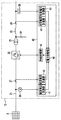
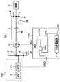
- FIG. 1 is a circuit diagram showing a power system and a relay according to a first embodiment.
- FIG. 1 is a circuit diagram showing a power conditioner of a power system according to a first embodiment.
- 5 is a graph for explaining the operation of the power conditioner according to the first embodiment.
- 5 is a graph for explaining the operation of the relay according to the first embodiment.
- 5 is a graph for explaining the operation of the relay according to the first embodiment.
- FIG. 7 is a circuit diagram showing a power system and a relay according to a modification of the first embodiment.
- FIG. 7 is a circuit diagram showing a power system and a relay according to a modification of the first embodiment.
- FIG. 7 is a circuit diagram showing a power system and a relay according to a second embodiment.
- FIG. 1 is a circuit diagram showing a power system 1 and a relay 73 according to a first embodiment.
- the power system 1 includes the grid interconnection power generation unit 2, a first bus 6 receiving the generated power of the grid interconnection power unit 2, a power transmission network 7 connected to the first bus 6, and power transmission network 7.
- a receiving second bus 9 and a load 8 connected to the second bus 9 are provided.
- the grid-connected power generation unit 2 includes a rotary generator 4, a first circuit breaker 5, a solar cell array 3, and a power conditioner system 12 which is a power conversion device.
- Power conditioner system is abbreviated as "PCS”.
- the rotary generator 4 is connected to the first bus 6 via the first circuit breaker 5.
- the rotary generator 4 supplies power to the transmission line 70 through the first bus 6.
- the rotating machine generator 4 is a fossil energy generator or a rotating machine generator mounted on a nuclear power generator.
- the rotary generator 4 performs grid-connected operation with a solar power generation system configured by the solar cell array 3 and the PCS 12.
- the PCS 12 includes an inverter circuit 22 and a power conversion control device 40, as shown in FIG.
- the PCS 12 is a power conversion device that converts direct current power into alternating current power.
- the inverter circuit 22 converts DC power from the solar cell array 3 into AC power.
- the AC power output from the inverter circuit 22 is supplied to the transmission line 70 via the first bus 6.
- the power conversion control device 40 controls the operation of the inverter circuit 22. Specifically, the power conversion control device 40 controls the switching of the switching elements included in the inverter circuit 22.
- the power conversion control device 40 is configured to be able to execute “current limit control” separately from steady state control.
- the “current limit control” according to the first embodiment suppresses or stops the output current of the inverter circuit when the voltage on the output side of the inverter circuit matches a predetermined condition.
- the detailed structure of the PCS 12 will be described later with reference to FIG.
- the power system 1 includes an instrument current transformer 69, a second circuit breaker 71, a relay 73, and an instrument transformer 75.
- the power transmission network 7 includes a power transmission line 70. One end of the power transmission line 70 is connected to the first bus 6, and the other end of the power transmission line 70 is connected to the second bus 9. Near the connection between the power transmission line 70 and the first bus 6, an instrument current transformer 69 and an instrument transformer 75 are provided. The current I measured by the instrumental current transformer 69 and the voltage V measured by the instrument transformer 75 are input to the relay 73.
- symbol 76 represents typically the condition which the ground fault 76 generate
- the relay 73 is a distance relay.
- the relay 73 can detect an accident of the transmission line 70 based on whether or not the impedance of the transmission line 70 matches a predetermined predetermined impedance condition.
- the relay 73 detects that an accident has occurred in the transmission line 70 in at least one of the case where the impedance of the transmission line 70 matches the predetermined impedance condition and the case where the above-described current limit control is performed.
- protective relays are usually installed in power plants or substations. Many protective relays for protecting the power transmission line 70 perform accident detection on the basis of electrical physical quantities on the power transmission line 70. In such a protective relay, it is considered that an accident has occurred in the transmission line 70 when the electrical physical quantity on the transmission line 70 exhibits a predetermined behavior. For example, when a ground fault occurs in the power transmission line 70, an excessive ground fault current should normally flow, so that the fault detection can be performed on the basis of such an increase in the current.
- An example of such a protective relay is a "distance relay".
- the relay 73 according to the first embodiment also has the same structure as the distance relay. The relay 73 monitors the impedance of the transmission line 70 to detect whether an accident has occurred. Also, the impedance is an electrical measure that determines the distance of the transmission line 70. The relay 73 can also know the distance to the fault point based on the impedance of the transmission line 70.
- the rotary generator 4, a transmission line 70 of the transmission network 7, and the PCS 12 are connected to the first bus 6.
- the rotary generator 4 and the PCS 12 are connected in parallel to the first bus 6, and the transmission line 70 receives the output power of these power generation facilities.
- the first bus 6 is a bus of the substation.
- FIG. 2 is a circuit diagram showing the PCS 12 of the power system 1 according to the first embodiment.
- the PCS 12 includes an inverter circuit 22 which is a power conversion unit, an interconnection transformer 23, a capacitor 24, a DC reactor 25, a DC voltage detector 26, a DC current detector 27, an AC voltage detector 28, and an AC voltage.
- a current detector 29 and a power conversion control device 40 are provided.
- the main circuit 21 is a circuit that supplies the power generated by the solar cell array 3 to the first bus 6.
- the main circuit 21 is provided with an inverter circuit 22, an interconnection transformer 23, a capacitor 24, and a DC reactor 25.
- the inverter circuit 22 converts the DC power supplied from the solar cell array 3 into AC power synchronized with the AC power supply of the first bus 6.
- the inverter circuit 22 outputs the converted AC power to the first bus 6 in order to supply the same.
- the interconnection transformer 23 is provided on the output side (AC side) of the inverter circuit 22.
- the interconnection transformer 23 transforms the alternating voltage output from the inverter circuit 22 into a voltage for supplying the first bus 6.
- the capacitor 24 and the DC reactor 25 constitute an AC filter.
- the AC filter is provided on the AC side of the interconnection transformer 23.
- the AC filter suppresses harmonic current flowing from the inverter circuit 22 to the first bus 6.
- the DC voltage detector 26 is provided on the input side (DC side) of the inverter circuit 22.
- the DC voltage detector 26 detects a DC voltage input from the solar cell array 3.
- the DC voltage detector 26 outputs the detected DC voltage to the power conversion control device 40.
- the direct current detector 27 is provided on the input side of the inverter circuit 22.
- the direct current detector 27 detects a direct current input from the solar cell array 3.
- the direct current detector 27 outputs the detected direct current to the power conversion control device 40.
- the AC voltage detector 28 is provided on the output side (AC side) of the DC reactor 25.
- the alternating voltage detector 28 detects an alternating voltage output from the inverter circuit 22.
- the AC voltage detector 28 outputs the detected AC voltage to the power conversion control device 40.
- the alternating current detector 29 is provided on the output side of the direct current reactor 25.
- An alternating current detector 29 detects an alternating current output from the inverter circuit 22.
- the alternating current detector 29 outputs the detected alternating current to the power conversion control device 40.
- the power conversion control device 40 is a control device that controls the inverter circuit 22.
- the power conversion control device 40 includes a DC voltage measurement unit 41, a DC current measurement unit 42, an AC voltage measurement unit 43, an AC current measurement unit 44, a power control unit 45, and a PWM (Pulse Width Modulation) control unit 46. Is equipped.
- the direct current voltage measurement unit 41 measures the direct current voltage input from the solar cell array 3 by the direct current voltage detected by the direct current voltage detector 26.
- the DC voltage measurement unit 41 outputs the measured DC voltage to the power control unit 45.
- the direct current measurement unit 42 measures the direct current input from the solar cell array 3 by the direct current detected by the direct current detector 27.
- the direct current measurement unit 42 outputs the measured direct current to the power control unit 45.
- the AC voltage measurement unit 43 measures the grid voltage of the first bus 6 (the output voltage of the inverter circuit 22) by the AC voltage detected by the AC voltage detector 28. The AC voltage measurement unit 43 outputs the measured AC voltage to the power control unit 45.
- the alternating current measurement unit 44 measures the alternating current output from the inverter circuit 22 by the alternating current detected by the alternating current detector 29.
- the alternating current measurement unit 44 outputs the measured alternating current to the power control unit 45.
- the power control unit 45 measures DC voltage measured by the DC voltage measurement unit 41, DC current measured by the DC current measurement unit 42, AC voltage measured by the AC voltage measurement unit 43, and AC current measurement unit 44. Based on the alternating current, arithmetic processing is performed to control the amount of electricity (current, voltage, power, etc.) output from the inverter circuit 22. The power control unit 45 outputs the calculated amount of electricity as an output command value to the inverter circuit 22 to the PWM control unit 46.
- the PWM control unit 46 generates a gate signal for performing PWM control of the inverter circuit 22 based on the output command value input from the power control unit 45.
- the PWM control unit 46 drives and controls the inverter circuit 22 by the generated gate signal.
- the inverter circuit 22 can output AC power having a desired frequency.
- the PCS 12 has a function of limiting the output current of the inverter circuit 22 in accordance with the voltage on the output side of the inverter circuit 22.
- One of the current limiting functions of the PCS 12 is called FRT (Fault Ride Through). According to FRT, even if the voltage on the load 8 side, that is, the voltage on the output side of the PCS 12 decreases, the PCS 12 performs current control so that the output current continues to flow while throttling for a predetermined time. Another one of the current limiting functions of the PCS 12 is that the PCS 12 shuts down the output current when the voltage on the output side of the PCS 12 falls below a predetermined voltage.
- the predetermined voltage may be set to, for example, about 20% of the steady-state voltage of the transmission line 70.
- the PCS 12 is configured to transmit the current control flag signal UCC to the relay 73 in response to the execution of the current limit control. Thus, information on current control performed by the PCS 12 can be transmitted to the relay 73.
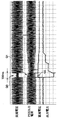
- FIG. 3 is a graph for explaining the operation of the PCS 12 according to the first embodiment.
- FIG. 3 is an example of a verification waveform of the FRT function, and shows a verification waveform by a mini model.
- the magnitude of the AC voltage output by the PCS 12 is suddenly and extremely reduced.
- FRT is activated.
- the portion indicated by the arrow Q1 in the PCS output current waveform represents that the current output from the PCS 12 is continued by the FRT.
- the portion indicated by the arrow Q2 in the DC voltage input to the PCS 12 represents a state in which the DC voltage is rising due to the reduction of the output power indicated by the arrow Q0.
- the DC voltage rise applied to the arrow Q2 is due to the characteristics of the solar cell.
- the relay 73 receives the control information from the PCS 12 and detects an accident of the transmission line 70 based on whether or not the current limit control is being performed.
- the relay 73 includes a plurality of input units, a determination logic circuit 74 that outputs a trip command signal Str2, an impedance determination unit 77, and a failsafe relay unit 78.
- the impedance determination unit is also referred to as a “Z determination unit”
- a fail-safe relay unit is referred to as an “FS relay unit”.
- the plurality of inputs provided in the relay 73 are a current value input that obtains the current value signal I measured by the instrument current transformer 69, and the magnitude of the voltage of the transmission line 70 measured by the instrument transformer 75.
- the determination logic circuit 74 includes a plurality of signals input to the current value input unit, the voltage value input unit, the communication input unit, and the trip state input unit, an impedance flag signal UZ output from the impedance determination unit 77, and a failsafe relay.
- a trip command signal Str2 is output to the second circuit breaker 71 based on the failsafe flag signal UFS output from the unit 78.
- the relay 73 includes the determination logic circuit 74.
- the determination logic circuit 74 includes a first AND gate 74a, an OR gate 74b, and a second AND gate 74c.
- the determination logic circuit 74 is constructed to perform the following first to third operation steps.
- the first AND gate 74a outputs a logical product of the current control flag signal UCC and the trip state signal Str1.
- the output of the first AND gate 74a is an output signal U0.
- the impedance flag signal UZ is determined by the impedance determination unit 77 performing the operation of FIG. 3 described later.
- the logical sum gate 74b outputs the logical sum of the impedance flag signal UZ and the output signal U0 of the first logical AND gate 74a.
- the OR output of the OR gate 74b is the flag signal U1.
- the second AND gate 74c outputs the logical product of the flag signal U1 and the failsafe flag signal UFS.
- a current control flag signal UCC is applied from the PCS 12 to the relay 73. Since the relay 73 takes in the contents of the current control flag signal UCC in the first to third operation steps described above, it is possible to use information on control of the PCS 12 as information for accident detection of the transmission line 70. it can.
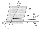
- FIG. 4 is a graph for explaining the operation of the relay 73 according to the first embodiment.
- FIG. 4 shows a case where the power transmission line 70 has an accident while the rotary generator 4 is in operation.
- the “impedance seen by the relay” will be described using FIG. 4.
- the items described individually are the contents implemented by the known distance relays, and are not new items. Therefore, the necessary matters will be mainly described, and the explanation will be simplified.
- the impedance straight line 81 of the transmission line 70, the operating range 80 of the relay 73, the offset 82 and the offset 83 of the operating range 80, and the load impedance 85 are illustrated on a complex number plane representing impedance. There is.
- the origin O of the RX orthogonal coordinate corresponds to the vicinity of the installation of the relay 73 in FIG.
- the mounting position of the instrument current transformer 69 on the power transmission line 70 is associated with the origin O.
- the intersection point P of the impedance straight line 81 and the operation range 80 represents the end of the protective range of the relay 73.
- the connection point between the power transmission line 70 and the second bus 9 is associated with the intersection point P.
- the relay 73 measures the magnitude of the impedance of the transmission line 70 based on the current flowing through the transmission line 70 and the voltage of the first bus 6. In normal operation where no accident occurs, the load impedance 85 located far from the origin O is dominant. In normal operation, the load impedance 85 is present at a considerable distance from the relay 73. On the other hand, if the impedance seen by the relay 73 is only the line impedance of the transmission line 70 due to the occurrence of an accident in the protected section, the impedance becomes an extremely small value. The impedance seen by the relay 73 moves into the working range 80 of the relay 73 from a distance, as shown by the arrow 84 in FIG. As a result, it is detected that the transmission line 70 has an accident.
- the impedance determination unit 77 determines whether or not an accident has occurred in the protected section on the basis of the fact that the impedance becomes smaller as the operating range 80 is entered. Incident detection based on impedance is performed, and the second circuit breaker 71 is quickly tripped.
- instrument current transformer 69 In general, instrument current transformer 69, relay 73 and instrument transformer 75 are installed in a substation.
- the relay 73 takes in the voltage value of the transmission line 70 via the instrument transformer 75, and takes in the current value of the transmission line 70 via the instrument current transformer 69.
- an instrumental current transformer 69 is installed between the first bus 6 and the second circuit breaker 71.
- the protection of the power transmission line 70 is preferably performed by a so-called OR operation that detects an accident based on the logical sum of a plurality of relays. This is to emphasize the certainty of protection.
- the plurality of relays include, for example, a short circuit differential relay and a short circuit impedance relay.
- the 87S relay is selected as the short protection relay for the main protection.
- a 44S relay is selected as a short circuit impedance relay for back protection.
- a range of about 80% of the total length of the first stage 44SX of the 44S relay or the transmission line 70 is treated as a protection range.
- the voltage detected by the 44S relay is zero for an accident near the installation point of the relay 73.
- the offset 82 and the offset 83 are preferably set in the operation range 80.
- “87S” and “44S” represent the device type and short circuit / ground fault distinction defined in the JIS standard or JEM standard, and since the information belongs to known techniques, detailed description will be omitted. Further, the correspondence between device types and numerals is partially different between the JIS standard and the IEC standard which is the overseas standard, and the 44th of the JIS standard corresponds to the 21st in the IEC.
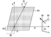
- FIG. 5 is a graph for explaining the operation of the relay 73 according to the first embodiment.
- FIG. 5 shows a case where there is an accident in the transmission line 70 when the rotary generator 4 is at rest and power generation is performed only by the solar cell array 3.
- the FRT operates to limit the magnitude of the output current by the PCS 12.
- the relay 73 may not be able to perform accurate impedance ranging. This is because the FRT of the PCS 12 operates earlier than the impedance ranging of the relay 73 is performed.
- the impedance can not reach the inside of the operating range 80 as shown by the arrow 86 in FIG. 5, which causes a problem that the short circuit accident determination does not work.
- the relay 73 erroneously measures the fault point.
- the impedance ranging function of the relay 73 operates normally as shown in FIG. 4, there is no problem. However, as shown in FIG. 5, the impedance ranging function may be disturbed. Therefore, in the first embodiment, the current output restriction state of the PCS 12 is input to the relay 73.
- the relay 73 outputs an open command, that is, a trip command, to the second circuit breaker 71 of the transmission line 70 when detecting the occurrence of an accident while incorporating the current output restriction state of the PCS 12 as the accident determination information. By tripping the second circuit breaker 71, it is possible to promptly take measures against an accident of the power transmission line 70.
- the relay 73 is preferably constructed to detect the occurrence of an accident when a plurality of accident detection conditions are satisfied.
- the condition is that the rotary generator 4 is not in operation and that the FRT function of the PCS 12 is working.
- a second accident detection condition for failsafe be also imposed.
- a condition may be added that the occurrence of an accident is detected when the voltage of the transmission line 70 is lower than or equal to a predetermined voltage by incorporating a failsafe relay unit in the relay 73.
- the fail safe relay unit may use, for example, a 27S undervoltage relay. Note that “27S” represents the device type and the short / ground fault classified by the JIS standard or the JEM standard, and since the information belongs to a known technology, the detailed description will be omitted.
- the decision logic circuit 74 According to the operation of FRT, when the current control flag signal UCC is high and the first circuit breaker 5 is in the cutoff state and the trip state signal Str1 is high, the output signal U0 of the first AND gate 74a is It becomes high. As described with reference to FIG. 4, when the impedance seen by the relay 73 falls within the operating range 80, the impedance determination unit 77 sets the impedance flag signal UZ to high. When at least one of the output signal U0 and the impedance flag signal UZ becomes high, the flag signal U1 becomes high.
- the failsafe flag signal UFS becomes high when the voltage of the transmission line 70 measured by the instrument transformer 75 becomes equal to or lower than a predetermined voltage.
- the first AND gate 74a makes the trip command signal Str2 a high output. If both the current control flag signal UCC and the impedance flag signal UZ are low, the first AND gate 74a holds the trip command signal Str2 low. If the failsafe flag signal UFS is low, the first AND gate 74a holds the trip command signal Str2 low. According to the above operation, the occurrence of an accident in the transmission line 70 can be accurately detected, whereby the second circuit breaker 71 can be accurately operated.
- the relay 73 it can be included in the condition of the accident detection whether or not the current limit control is performed, so that it is accurate even if the electrical physical quantity on the transmission line 70 is affected by the control of the PCS 12 Accident detection can be performed.
- the notification signal may be output to the outside of the relay 73 when the output of the trip command signal Str2 becomes high. Thus, the fact that an accident has been detected in the power transmission line 70 may be notified to the outside.
- the relay 73 may be modified as follows.
- the relay 73 detects an accident by a logic circuit as an example, but as a modification, a determination program may be executed on a microcomputer instead of the logic circuit.
- Digital protective relays are widely used as protective relays such as distance relays.
- the digital protection relay comprises a CPU, an analog filter, an A / D converter, a digital filter, and a memory. The function of the relay is exhibited by the CPU executing the accident detection program and the protection operation program stored in the memory.
- the first to third operation steps performed by the determination logic circuit 74 may be constructed on software.
- the relay 73 can perform fault point ranging based on the impedance by using the current associated with the power generation for this fixed period.
- the relay 73 can perform the accident detection using the current control flag signal UCC, instead of the accident detection based on the impedance. Therefore, according to the first embodiment, impedance fault point ranging by the distance relay and fault detection using the current control flag signal UCC can be selectively used according to the situation.
- the PCS 12 since the current limit control includes the FRT, the PCS 12 transmits the current control flag signal UCC to the relay 73 according to the execution of the FRT.
- the relay 73 performs accident detection based on the current control flag signal UCC.
- the PCS 12 may transmit the current control flag signal UCC to the relay 73 according to the execution of the shutdown control.
- FIG. 6 is a circuit diagram showing a power system 1 and a relay 73 according to a modification of the first embodiment.
- the storage battery 13 is connected to the PCS 12 instead of the solar cell array 3.
- a wind power generation system 14 may be connected to the PCS 12.
- the wind power generation system 14 includes a wind power generator 15 and a power converter 16.
- the AC power generated by the wind power generator 15 depends on the strength of the wind. Since the strength of the wind changes from moment to moment, the AC power generated by the wind power generator 15 is difficult to stabilize. Therefore, it is preferable to convert the AC power from the wind power generator 15 into a constant DC voltage by the power converter 16 and further convert the DC voltage into stable AC power by the PCS 12.
- two or more DC power supply systems may be selected from the DC power supply system group including the solar cell array 3, the storage battery 13, and the wind power generation system 14, and the selected DC The power supply systems may be connected to the first bus 6 respectively.
- a plurality of DC power supply systems may be operated in parallel.
- FIG. 8 is a circuit diagram showing a power system 101 and a relay 173 according to the second embodiment.
- the power system 101 of the second embodiment is different from that of the first embodiment in the following two points.
- the rotary generator 4 is not connected to the first bus 6, and only the series circuit of the PCS 12 and the solar cell array 3 is connected to the first bus 6.
- the relay 73 is replaced by a relay 173.
- the relay 173 includes a determination logic circuit 174 in place of the determination logic circuit 74. Except for these points, the power system 101 of the second embodiment has the same configuration as that of the first embodiment.
- the determination logic circuit 174 includes a fourth AND gate 174a. Since the impedance flag signal UZ is not used, the relay 173 may not perform current acquisition using the instrument current transformer 69.
- the fourth AND gate 174a calculates the logical product of the current control flag signal UCC and the failsafe flag signal UFS. Thereby, the fourth AND gate 174a trips when the current control flag signal UCC becomes high in response to the activation of FRT and the failsafe flag signal UFS becomes high in response to the voltage drop of the transmission line 70.
- the command signal Str2 can be made high. Therefore, as in the first embodiment, whether or not the current limit control is performed can be included in the condition of the accident detection, so the electrical physical quantity on the transmission line 70 is affected by the control of the PCS 12. Even accurate accident detection can be performed.
- the structure of the relay 173 may be made on the basis of the internal configuration of various protective relays other than the distance relay.
- the determination logic circuit 174 may be realized by software as in the first embodiment.
- the storage battery 13 or the wind power generation system 14 may be connected to the first bus 6 as shown in FIGS. 6 and 7.
- Two or more DC power supply systems selected from the DC power supply system group consisting of the solar cell array 3, the storage battery 13, and the wind power generation system 14 may be connected to the first bus 6.
Landscapes
- Emergency Protection Circuit Devices (AREA)
- Engineering & Computer Science (AREA)
- Power Engineering (AREA)
- Supply And Distribution Of Alternating Current (AREA)
- Inverter Devices (AREA)
Abstract
電力システムは、パワーコンディショナと、パワーコンディショナの電流制限制御が実行されているか否かに基づいて送電線の事故発生を検出する継電器と、を備える。パワーコンディショナは、直流電源からの直流電力を交流電力に変換し且つ交流電力を送電線に供給するインバータ回路と、インバータ回路の出力側の電圧が予め定めた条件に合致したときにインバータ回路の出力電流を抑制又は停止させる電流制限制御を実行可能に構築された制御回路と、を有する。電力システムは、送電線に電力を供給する回転機発電機を備えてもよい、継電器は、送電線のインピーダンスが予め定めた所定インピーダンス条件に合致したか否かに基づいて送電線の事故を検出する距離継電器であってもよい。距離継電器は、インピーダンスの所定インピーダンス条件への合致または電流制限制御の実行があったときに、送電線に事故が発生したことを検出してもよい。
Description
本発明は、電力システムおよび継電器に関するものである。
従来、例えば日本特開2015-065719号公報に記載されているように、太陽光発電部、パワーコンディショナ、および連系保護装置を備えた太陽光発電設備用の系統連系装置が知られている。この系統連系装置では、パワーコンディショナと配電系統の間に、連係保護装置が設けられている。連係保護装置は開閉器を含んでおり、開閉器によって配電系統からパワーコンディショナおよび太陽光発電部を切り離すことができる。この公報の段落0060では、開閉器に保護動作を行わせるために必要な保護継電器を設けてもよいことが僅かに言及されている。
エネルギー源として化石エネルギーと非化石エネルギーがあり、非化石エネルギーは原子力と再生可能エネルギーに分類される。近年では再生可能エネルギーを利用した電力システムの普及がますます進められている。再生可能エネルギー電力システムと、それ以外の化石エネルギー等の電力システムとを並列運転させる、いわゆる系統連系システムが普及している。また、再生可能エネルギー電力システムのみで構成され、系統連系を行わない、いわゆる独立電源システムも実用化されている。
再生可能エネルギー電力システムは、パワーコンディショナを含んでいる。パワーコンディショナは、内蔵したインバータ回路を駆動することで、直流電力を所望の交流電力に変換する。
再生可能エネルギー電力システムの電力も、既設の電力系統と同様に、送電網の送電線を介して需要家へと供給される。一般的に、送電線に事故があったときのために、送電網には保護継電器が設けられている。送電線保護用の保護継電器には、送電線上の電気的物理量を根拠として事故検出を行うものも多い。このような保護継電器では、送電線上の電気的物理量が予め定めたふるまいを見せたときに送電線に事故が発生したとみなされる。例えば、送電線に地絡事故が発生した場合は通常であれば過大な地絡電流が流れるはずなので、そのような電流の増大を根拠として事故発生を検出することができる。
パワーコンディショナは、自己の出力側の電圧に応じて、出力電流を制限する機能を持っている。この出力電流制限によってパワーコンディショナが出力電流を抑制すると、送電線に過大な地絡電流が流れることは防止される。しかしながら、この出力電流抑制は、パワーコンディショナを含まない従来の電力システムで短絡事故が発生したときの電流挙動とは異なるものである。パワーコンディショナの出力電流抑制が、従来の継電器にとって予定外の電流挙動を引き起こしてしまう。パワーコンディショナを含む電力システムでは、パワーコンディショナ特有の電流制御が生ずることによって継電器の事故検出精度を低下させるおそれがあるという問題があった。
この出願は、上述のような課題を解決するためになされたもので、パワーコンディショナを含む電力システムにおいても事故検出を正確に行うことができる継電器および電力システムを提供することを目的とする。
本願の第一発明にかかる電力システムは、
直流電源からの直流電力を交流電力に変換し且つ前記交流電力を送電線に供給するインバータ回路と、前記インバータ回路の出力側の電圧が予め定めた条件に合致したときに前記インバータ回路の出力電流を抑制又は停止させる電流制限制御を実行可能に構築された制御回路と、を有するパワーコンディショナと、
前記電流制限制御が実行されているか否かに基づいて前記送電線の事故発生を検出する継電器と、
を備える。
直流電源からの直流電力を交流電力に変換し且つ前記交流電力を送電線に供給するインバータ回路と、前記インバータ回路の出力側の電圧が予め定めた条件に合致したときに前記インバータ回路の出力電流を抑制又は停止させる電流制限制御を実行可能に構築された制御回路と、を有するパワーコンディショナと、
前記電流制限制御が実行されているか否かに基づいて前記送電線の事故発生を検出する継電器と、
を備える。
本願の第二発明にかかる継電器は、
パワーコンディショナの制御内容を示す信号を受信するための第一入力部と、
送電線の電圧の大きさに応じた信号を受信するための第二入力部と、
前記パワーコンディショナが予め定めた電流制限制御を実行したことを示す特定信号を前記第一入力部から受信しかつ前記送電線の電圧が予め定めた電圧以下となった場合に、前記送電線の事故発生を検出する判定部と、
を備える。
パワーコンディショナの制御内容を示す信号を受信するための第一入力部と、
送電線の電圧の大きさに応じた信号を受信するための第二入力部と、
前記パワーコンディショナが予め定めた電流制限制御を実行したことを示す特定信号を前記第一入力部から受信しかつ前記送電線の電圧が予め定めた電圧以下となった場合に、前記送電線の事故発生を検出する判定部と、
を備える。
上記電力システムまたは上記継電器によれば、パワーコンディショナの電流制限制御が行われているか否かを事故検出の条件に含ませることができる。これにより、送電線上の電気的物理量がパワーコンディショナの制御によって影響を受けても、事故発生を正確に検出することができる。
図1は、実施の形態1にかかる電力システム1および継電器73を示す回路図である。電力システム1は、系統連系発電部2と、系統連系発電部2の発電電力を受ける第一母線6と、第一母線6と接続した送電網7と、送電網7を介して電力を受け取る第二母線9と、第二母線9と接続した負荷8と、を備えている。
系統連系発電部2は、回転機発電機4と、第一遮断器5と、太陽電池アレイ3と、電力変換装置であるパワーコンディショナシステム12と、を備えている。「パワーコンディショナシステム」を、「PCS」とも略称する。
回転機発電機4は、第一遮断器5を介して第一母線6に接続している。回転機発電機4は、第一母線6を通じて、送電線70に電力を供給する。回転機発電機4は、化石エネルギー発電機あるいは原子力発電機に搭載された回転機発電機である。回転機発電機4は、太陽電池アレイ3およびPCS12で構成される太陽光発電システムとともに系統連系運転をする。
PCS12は、図2に示されているとおり、インバータ回路22と、電力変換制御装置40とを備えている。PCS12は、直流電力を交流電力に変換する電力変換装置である。インバータ回路22は、太陽電池アレイ3からの直流電力を交流電力に変換する。インバータ回路22が出力する交流電力は、第一母線6を介して送電線70に供給される。電力変換制御装置40は、インバータ回路22の動作を制御するものであり、具体的にはインバータ回路22に含まれるスイッチング素子のスイッチングを制御する。電力変換制御装置40は、定常制御とは別に、「電流制限制御」を実行可能に構築されている。実施の形態1にかかる「電流制限制御」は、インバータ回路の出力側の電圧が予め定めた条件に合致したときにインバータ回路の出力電流を抑制又は停止させるものである。PCS12の詳細な構造は、図2を参照しつつ後ほど説明する。
電力システム1は、計器用変流器69と、第二遮断器71と、継電器73と、計器用変圧器75と、を備えている。送電網7は、送電線70を備えている。送電線70の一端が第一母線6と接続し、送電線70の他端が第二母線9に接続している。送電線70と第一母線6との接続部付近には、計器用変流器69および計器用変圧器75が設けられている。計器用変流器69で計測された電流Iと、計器用変圧器75で計測された電圧Vとが、継電器73に入力される。なお、符号76は、送電線70に地絡事故76が発生した状況を模式的に表したものである。
継電器73は、距離継電器である。継電器73は、送電線70のインピーダンスが予め定めた所定インピーダンス条件に合致したか否かに基づいて送電線70の事故を検出することができる。継電器73は、送電線70のインピーダンスが所定インピーダンス条件に合致した場合と上記の電流制限制御の実行があった場合の少なくとも一方の場合に、送電線70に事故が発生したことを検出する。
一般的に、保護継電器は、発電所あるいは変電所に設置されるのが普通である。送電線70を保護するための保護継電器には、送電線70上の電気的物理量を根拠として事故検出を行うものも多い。このような保護継電器では、送電線70上の電気的物理量が予め定めたふるまいを見せたときに送電線70に事故が発生したとみなされる。例えば、送電線70に地絡事故が発生した場合は通常であれば過大な地絡電流が流れるはずなので、そのような電流の増大を根拠として事故検出を行うことができる。このような保護継電器の一例として「距離継電器」がある。実施の形態1にかかる継電器73も、距離継電器と同様の構造を備えている。継電器73は送電線70のインピーダンスを監視することによって事故が発生しているか否かを検出する。また、インピーダンスは送電線70の距離を決める電気的尺度となる。継電器73は送電線70のインピーダンスに基づいて事故点までの距離を知ることもできる。
第一母線6には、回転機発電機4と、送電網7の送電線70と、PCS12と、が接続している。第一母線6には、回転機発電機4とPCS12とが並列接続されており、送電線70はこれらの発電設備の出力電力を受け取る。第一母線6は、変電所の母線である。
図2は、実施の形態1にかかる電力システム1のPCS12を示す回路図である。PCS12は、電力変換部であるインバータ回路22と、連系トランス23と、コンデンサ24と、直流リアクトル25と、直流電圧検出器26と、直流電流検出器27と、交流電圧検出器28と、交流電流検出器29と、電力変換制御装置40と、を備えている。
主回路21は、太陽電池アレイ3により発電された電力を第一母線6に供給する回路である。主回路21には、インバータ回路22、連系トランス23、コンデンサ24、及び直流リアクトル25が設けられている。
インバータ回路22は、太陽電池アレイ3から供給される直流電力を第一母線6の交流電源と同期する交流電力に変換する。インバータ回路22は、変換した交流電力を第一母線6に供給するために出力する。
連系トランス23は、インバータ回路22の出力側(交流側)に設けられている。連系トランス23は、インバータ回路22から出力される交流電圧を第一母線6に供給するための電圧に変圧する。
コンデンサ24及び直流リアクトル25は、交流フィルタを構成する。交流フィルタは、連系トランス23の交流側に設けられている。交流フィルタは、インバータ回路22から第一母線6に流出する高調波電流を抑制する。
直流電圧検出器26は、インバータ回路22の入力側(直流側)に設けられている。直流電圧検出器26は、太陽電池アレイ3から入力される直流電圧を検出する。直流電圧検出器26は、検出した直流電圧を電力変換制御装置40に出力する。
直流電流検出器27は、インバータ回路22の入力側に設けられている。直流電流検出器27は、太陽電池アレイ3から入力される直流電流を検出する。直流電流検出器27は、検出した直流電流を電力変換制御装置40に出力する。
交流電圧検出器28は、直流リアクトル25の出力側(交流側)に設けられている。交流電圧検出器28は、インバータ回路22から出力される交流電圧を検出する。交流電圧検出器28は、検出した交流電圧を電力変換制御装置40に出力する。
交流電流検出器29は、直流リアクトル25の出力側に設けられている。交流電流検出器29は、インバータ回路22から出力される交流電流を検出する。交流電流検出器29は、検出した交流電流を電力変換制御装置40に出力する。
電力変換制御装置40は、インバータ回路22を制御する制御装置である。電力変換制御装置40は、直流電圧計測部41と、直流電流計測部42と、交流電圧計測部43と、交流電流計測部44、電力制御部45と、PWM(Pulse Width Modulation)制御部46とを備えている。
直流電圧計測部41は、直流電圧検出器26により検出された直流電圧により、太陽電池アレイ3から入力される直流電圧を計測する。直流電圧計測部41は、計測した直流電圧を電力制御部45に出力する。
直流電流計測部42は、直流電流検出器27により検出された直流電流により、太陽電池アレイ3から入力される直流電流を計測する。直流電流計測部42は、計測した直流電流を電力制御部45に出力する。
交流電圧計測部43は、交流電圧検出器28により検出された交流電圧により、第一母線6の系統電圧(インバータ回路22の出力電圧)を計測する。交流電圧計測部43は、計測した交流電圧を電力制御部45に出力する。
交流電流計測部44は、交流電流検出器29により検出された交流電流により、インバータ回路22から出力される交流電流を計測する。交流電流計測部44は、計測した交流電流を電力制御部45に出力する。
電力制御部45は、直流電圧計測部41により計測された直流電圧、直流電流計測部42により計測された直流電流、交流電圧計測部43により計測された交流電圧、及び交流電流計測部44により計測された交流電流に基づいて、インバータ回路22から出力させる電気量(電流、電圧、電力など)を制御するための演算処理をする。電力制御部45は、演算された電気量をインバータ回路22に対する出力指令値として、PWM制御部46に出力する。
PWM制御部46は、電力制御部45から入力された出力指令値に基づいて、インバータ回路22をPWM制御するためのゲート信号を生成する。PWM制御部46は、生成したゲート信号により、インバータ回路22を駆動制御する。これにより、インバータ回路22から、所望の周波数を持つ交流電力を出力することができる。
PCS12は、インバータ回路22の出力側の電圧に応じて、インバータ回路22の出力電流を制限する機能を持っている。PCS12の電流制限機能の一つは、FRT(Fault Ride Through)と呼ばれるものである。FRTによれば、負荷8側の電圧つまりPCS12の出力側の電圧が低下しても、一定時間は出力電流を絞りつつ流し続けるようにPCS12が電流制御を行う。PCS12の電流制限機能の他の一つは、自己の出力側の電圧が予め定めた所定電圧以下になるとPCS12が出力電流をシャットダウンするという機能である。所定電圧は、例えば送電線70の定常電圧の20%程度に設定されてもよい。PCS12は、電流制限制御の実行に応じて、継電器73に電流制御フラグ信号UCCを送信するように構築されている。これにより、PCS12が行っている電流制御の情報を、継電器73に伝えることができる。
図3は、実施の形態1にかかるPCS12の動作を説明するためのグラフである。図3は、FRT機能の検証波形の一例であり、ミニモデルによる検証波形を示している。矢印Q0が指し示す区間100msの領域では、PCS12の出力する交流電圧の大きさが突然かつ極端に低下している。このような電圧低下が起きると、FRTが作動する。PCS出力電流波形のうち矢印Q1で指し示された部分は、PCS12からの電流出力がFRTによって継続されている様子を表している。PCS12に入力される直流電圧のうち矢印Q2で指し示された部分は、矢印Q0で指し示した出力電力の低下により直流電圧が上昇している様子を表している。矢印Q2にかかる直流電圧上昇は、太陽電池の特性によるものである。
継電器73は、PCS12から制御情報を受け取ったうえで、電流制限制御が実行されているか否かに基づいて送電線70の事故を検出する。継電器73は、複数の入力部と、トリップ命令信号Str2を出力する判定論理回路74と、インピーダンス判定部77と、フェールセーフ継電器部78と、を備えている。図1では、便宜上、インピーダンス判定部を「Z判定部」とも称し、フェールセーフ継電器部を「FS継電器部」としている。継電器73が備える複数の入力部は、計器用変流器69で計測された電流値信号Iを取得する電流値入力部と、計器用変圧器75で計測された送電線70の電圧の大きさに応じた電圧値信号Vを受信するための電圧値入力部と、PCS12と通信することで電流制御フラグ信号UCCを受信するための通信入力部と、第一遮断器5のトリップ状態を示すトリップ状態信号Str1を取得するためのトリップ状態入力部と、を含む。判定論理回路74は、電流値入力部、電圧値入力部、通信入力部、およびトリップ状態入力部に入力される複数の信号と、インピーダンス判定部77の出力するインピーダンスフラグ信号UZと、フェールセーフ継電器部78の出力するフェールセーフフラグ信号UFSとに基づいて、第二遮断器71に対してトリップ命令信号Str2を出力する。
継電器73の具体的な内部回路構造は、公知の各種の距離継電器をベースとすることができる。実施の形態1では、継電器73が判定論理回路74を備えている。判定論理回路74は、第一論理積ゲート74aと、論理和ゲート74bと、第二論理積ゲート74cと、を含んでいる。判定論理回路74は、下記の第一演算ステップ~第三演算ステップを行うように構築されている。第一演算ステップとして、第一論理積ゲート74aは、電流制御フラグ信号UCCと、トリップ状態信号Str1と、の論理積を出力する。第一論理積ゲート74aの出力を出力信号U0とする。インピーダンスフラグ信号UZは、インピーダンス判定部77が後述する図3の動作を実行することによって決定される。第二演算ステップとして、論理和ゲート74bは、インピーダンスフラグ信号UZと、第一論理積ゲート74aの出力信号U0との論理和を出力する。論理和ゲート74bの論理和出力が、フラグ信号U1である。第三演算ステップとして、第二論理積ゲート74cは、フラグ信号U1とフェールセーフフラグ信号UFSとの論理積を出力する。
PCS12が電流制限制御を実行すると、PCS12から電流制御フラグ信号UCCが継電器73に与えられる。継電器73は、電流制御フラグ信号UCCの内容を上記の第一演算ステップ~第三演算ステップに取り込んでいるので、PCS12の制御の情報を送電線70の事故検出のための情報として利用することができる。
以下、図1に加えて図4~図5を更に参照しつつ、継電器73の動作を説明する。
図4は、実施の形態1にかかる継電器73の動作を説明するためのグラフである。図4は、回転機発電機4の運転中に送電線70に事故があった場合を表している。以下、図4を用いて、「継電器が見るインピーダンス」について説明する。ただし、個々で説明する事項は既に公知の距離継電器で実施されている内容であり、新規な事項ではない。このため、必要事項を中心に説明し、説明を簡略化する。図4には、インピーダンスを表す複素数平面に、送電線70のインピーダンス直線81と、継電器73の動作範囲80と、動作範囲80が持つオフセット82およびオフセット83と、負荷インピーダンス85と、が図示されている。なお、RX直交座標の原点Oは、図1では継電器73の設置付近に対応している。図1では便宜上、送電線70上における計器用変流器69の取り付け位置を、原点Oに対応付けている。また、RX直交座標で、インピーダンス直線81と動作範囲80との交点Pが、継電器73の保護範囲の末端を表している。図1では、便宜上、送電線70と第二母線9との接続点を、交点Pと対応付けている。
継電器73は、送電線70に流れる電流と第一母線6の電圧に基づいて、送電線70のインピーダンスの大きさを測っている。事故の発生していない通常の運転では、原点Oから遠方にある負荷インピーダンス85が支配的である。通常の運転では、継電器73から見て相当な遠方に負荷インピーダンス85が存在している状態となる。一方、保護区間内で事故が生ずることで継電器73が見るインピーダンスが送電線70の線路インピーダンスのみとなると、インピーダンスが極端に小さな値となる。継電器73が見るインピーダンスは、図4の矢印84に示すように、遠方から、継電器73の動作範囲80内へ移動する。その結果、送電線70に事故があったことが検出される。インピーダンス判定部77は、上述の内容を実行することで、動作範囲80内に入るほどにインピーダンスが小さくなったことを根拠として保護区間内に事故が生じたか否かを判定する。インピーダンスに基づく事故検出がなされ、第二遮断器71が速やかにトリップされる。
一般的に、計器用変流器69、継電器73および計器用変圧器75は、変電所内に設置されている。継電器73は、計器用変圧器75を介して送電線70の電圧値を取り込み、計器用変流器69を介して送電線70の電流値を取り込む。図1では、第一母線6と第二遮断器71の間に計器用変流器69が設置されている。
送電線70の保護は、複数の継電器の論理和に基づいて事故を検出するいわゆるOR運用によって行われることが好ましい。これは保護の確実性を重視するためである。複数の継電器は、例えば短絡差動継電器と短絡インピーダンス継電器とを含んでいる。短絡作動継電器には、例えば主保護のために87S継電器が選定される。短絡インピーダンス継電器には、例えば後備保護のために44S継電器が選定される。一例として、44S継電器の第一段44SXあるいは送電線70の全長の80%程度の範囲が、保護範囲として取り扱われる。また、44S継電器が検知する電圧は、継電器73の設置点近傍での事故に対しては、ゼロになる。仮に動作範囲80がR軸のプラス側およびX軸のプラス側のみで設定されている場合、44S継電器が検知する電圧がゼロになると正常動作ができないおそれがある。そこで、動作範囲80にオフセット82およびオフセット83が設定されることが好ましい。なお、「87S」および「44S」は、JIS規格あるいはJEM規格で定められているデバイス種類および短絡/地絡の別を表しており、公知技術に属する情報なので詳細な説明は省略する。また、JIS規格と、海外規格であるIEC規格とではデバイス種類と数字との対応が一部異なり、JIS規格の44番はIECでは21番に対応している。
図5は、実施の形態1にかかる継電器73の動作を説明するためのグラフである。図5は、回転機発電機4が休止中であり且つ太陽電池アレイ3のみで発電が行われている場合において、送電線70に事故があった場合を表している。第一母線6の電圧が低下すると、FRTが作動することでPCS12が出力電流の大きさを制限する。PCS12が電流制限を行うと、継電器73が正確なインピーダンス測距を実施できなくなるおそれがある。継電器73のインピーダンス測距が実施されるよりも早く、PCS12のFRTが作動するからである。この場合、電圧は低下しているものの、図5の矢印86のようにインピーダンスが動作範囲80の内側に到達できないので、短絡事故判断が働かないという不具合が生じる。その結果、継電器73が事故点を誤計測してしまう。
図4のように継電器73のインピーダンス測距機能が正常動作していれば問題は無い。しかし図5のようにインピーダンス測距機能が妨げられることもありうる。そこで、実施の形態1では、継電器73に、PCS12の電流出力制限状態を入力している。継電器73は、PCS12の電流出力制限状態を事故判定情報として取り入れつつ、事故発生を検出した場合には送電線70の第二遮断器71に対して開放指令すなわちトリップ指令を出力する。第二遮断器71をトリップさせることにより、送電線70の事故に対して速やかに対策を施すことができる。
実際には、継電器73は、複数の事故検出条件が満たされた場合に事故発生を検出するように構築されることが好ましい。第一事故検出条件の一例としては、回転機発電機4が運転しておらず、尚且つPCS12のFRT機能が働いていることを条件とすることが好ましい。この第一事故検出条件の他に、フェールセーフのための第二事故検出条件も課せられることが好ましい。第二事故検出条件の一例として、フェールセーフ継電器部を継電器73に内蔵させることで、送電線70の電圧が予め定めた所定電圧以下であるときに事故発生を検出するという条件を加えてもよい。フェールセーフ継電器部は、例えば、27S不足電圧継電器を用いてもよい。なお、「27S」は、JIS規格あるいはJEM規格で定められているデバイス種類および短絡/地絡の別を表しており、公知技術に属する情報なので詳細な説明は省略する。
図1を参照しつつ、判定論理回路74の具体的動作についてより詳細に説明する。FRTの作動に応じて電流制御フラグ信号UCCがハイとなり、第一遮断器5が遮断状態にあることでトリップ状態信号Str1がハイとなっていると、第一論理積ゲート74aの出力信号U0がハイとなる。図4で説明したように継電器73が見るインピーダンスが動作範囲80内に入った場合には、インピーダンス判定部77がインピーダンスフラグ信号UZをハイとする。出力信号U0とインピーダンスフラグ信号UZの少なくとも一方がハイになると、フラグ信号U1がハイとなる。実施の形態1では、計器用変圧器75で計測した送電線70の電圧が、予め定めた所定電圧以下となったときに、フェールセーフフラグ信号UFSがハイとなる。インピーダンスフラグ信号UZまたは電流制御フラグ信号UCCがハイとなり、かつフェールセーフフラグ信号UFSがハイとなった場合に、第一論理積ゲート74aがトリップ命令信号Str2をハイ出力とする。電流制御フラグ信号UCCとインピーダンスフラグ信号UZの両方がローである場合には、第一論理積ゲート74aはトリップ命令信号Str2をローに保持する。また、フェールセーフフラグ信号UFSがローであれば、第一論理積ゲート74aはトリップ命令信号Str2をローに保持する。以上の動作によれば、送電線70に事故が発生したことを正確に検出し、それにより第二遮断器71を正確に作動させることができる。継電器73によれば、電流制限制御が行われているか否かを事故検出の条件に含ませることができるので、送電線70上の電気的物理量がPCS12の制御によって影響を受けても、正確な事故検出を行うことができる。トリップ命令信号Str2の出力がハイとなったときに継電器73の外部に報知信号を出力してもよい。これにより送電線70で事故が検出されたことを外部に報知してもよい。
なお、継電器73は次のように変形してもよい。実施の形態1では一例として論理回路によって継電器73が事故検出を行っているが、変形例として論理回路の代わりにマイコン上で判定プログラムを実行させてもよい。距離継電器などの保護継電器として、ディジタル保護継電器が普及している。ディジタル保護継電器は、CPU、アナログフィルタ、A/Dコンバータ、ディジタルフィルタ、およびメモリを備えている。CPUが、メモリに記憶された事故検出プログラムおよび保護動作プログラムを実行することで継電器の機能が発揮されている。上記の判定論理回路74で行われる上記第1演算ステップ~第3演算ステップをソフトウェア上で構築すればよい。
なお、実施の形態1にかかる電力システム1では、回転機発電機4が運転されている場合には、送電線70に事故が発生しても回転機発電機4が急停止せずに一定期間は発電を続ける。この一定期間の発電に伴う電流を利用して、継電器73がインピーダンスに基づく事故点測距を行うことができる。その一方で、回転機発電機4による発電が停止している場合には、太陽電池アレイ3およびPCS12を介して得られる再生可能エネルギー発電電力のみが送電線70へ供給される。この場合にも、実施の形態1にかかる継電器73は、インピーダンスに基づく事故検出に代えて、電流制御フラグ信号UCCを利用した事故検出を行うことができる。従って、実施の形態1によれば、距離継電器によるインピーダンス事故点測距と、電流制御フラグ信号UCCを利用した事故検出とを、状況に応じて使い分けることができる。
なお、実施の形態1では、電流制限制御がFRTを含んでいるので、PCS12はFRTの実行に応じて継電器73に電流制御フラグ信号UCCを送信する。継電器73は、電流制御フラグ信号UCCに基づいて事故検出を行っている。一方、変形例として、仮に電流制限制御にFRTが含まれずシャットダウン制御のみである場合には、PCS12はシャットダウン制御の実行に応じて継電器73に電流制御フラグ信号UCCを送信するようにしてもよい。
図6は、実施の形態1の変形例にかかる電力システム1および継電器73を示す回路図である。図6では、太陽電池アレイ3に代えて、蓄電池13がPCS12に接続されている。図7に示すように、蓄電池13に代えて、風力発電システム14がPCS12に接続されてもよい。風力発電システム14は、風力発電機15および電力変換装置16を含んでいる。風力発電機15の発電する交流電力は、風の強さに左右される。風の強さは時々刻々と変化するので、風力発電機15の発電する交流電力は安定しにくい。そこで、電力変換装置16により風力発電機15からの交流電力を一定の直流電圧に変換し、さらにこの直流電圧をPCS12で安定した交流電力に変換することが好ましい。他の変形例として、太陽電池アレイ3、蓄電池13、および風力発電システム14からなる直流電源システム群から二つ以上の直流電源システムを選択してもよく、複数のPCS12を介してこの選択した直流電源システムをそれぞれ第一母線6に接続してもよい。これにより複数の直流電源システムを並行運転させてもよい。
実施の形態2.
図8は、実施の形態2にかかる電力システム101および継電器173を示す回路図である。実施の形態2の電力システム101が実施の形態1と異なる点としては、次の二点がある。第一の相違点として、第一母線6に回転機発電機4が接続されておらず、第一母線6にPCS12および太陽電池アレイ3の直列回路のみが接続されている。第二の相違点として、実施の形態2では継電器73が継電器173に置換されている。継電器173は、判定論理回路74に代えて、判定論理回路174を備えている。これらの点を除いて、実施の形態2の電力システム101は、実施の形態1と同様の構成を備えている。
図8は、実施の形態2にかかる電力システム101および継電器173を示す回路図である。実施の形態2の電力システム101が実施の形態1と異なる点としては、次の二点がある。第一の相違点として、第一母線6に回転機発電機4が接続されておらず、第一母線6にPCS12および太陽電池アレイ3の直列回路のみが接続されている。第二の相違点として、実施の形態2では継電器73が継電器173に置換されている。継電器173は、判定論理回路74に代えて、判定論理回路174を備えている。これらの点を除いて、実施の形態2の電力システム101は、実施の形態1と同様の構成を備えている。
判定論理回路174は、第四論理積ゲート174aを備える。インピーダンスフラグ信号UZが使用されないので、継電器173は計器用変流器69を用いた電流取込を行わなくともよい。第四論理積ゲート174aは、電流制御フラグ信号UCCと、フェールセーフフラグ信号UFSとの論理積を演算する。これにより、FRTの作動に応答して電流制御フラグ信号UCCがハイとなり、かつ送電線70の電圧低下に応じてフェールセーフフラグ信号UFSがハイとなった場合に、第四論理積ゲート174aがトリップ命令信号Str2をハイとすることができる。従って、実施の形態1と同様に、電流制限制御が行われているか否かを事故検出の条件に含ませることができるので、送電線70上の電気的物理量がPCS12の制御によって影響を受けても、正確な事故検出を行うことができる。実施の形態1とは異なりインピーダンスフラグ信号Zが不要なので、継電器173の構造は距離継電器以外の各種の保護継電器の内部構成をベースとして作られても良い。
実施の形態1と同様の変形を適用しても良い。判定論理回路174をソフトウェアで実現しても良いことは、実施の形態1と同様である。図6および図7のように蓄電池13または風力発電システム14を第一母線6に接続してもよい。太陽電池アレイ3、蓄電池13、および風力発電システム14からなる直流電源システム群から選択した二つ以上の直流電源システムを、第一母線6に接続してもよい。
1、101 電力システム、2 系統連系発電部、3 太陽電池アレイ、4 回転機発電機、5 第一遮断器、6 第一母線、7 送電網、8 負荷、9 第二母線、12 パワーコンディショナシステム(PCS)、13 蓄電池、14 風力発電システム、15 風力発電機、16 電力変換装置、21 主回路、22 インバータ回路、23 連系トランス、24 コンデンサ、25 直流リアクトル、26 直流電圧検出器、27 直流電流検出器、28 交流電圧検出器、29 交流電流検出器、40 電力変換制御装置、41 直流電圧計測部、42 直流電流計測部、43 交流電圧計測部、44 交流電流計測部、45 電力制御部、46 PWM制御部、69 計器用変流器、70 送電線、71 第二遮断器、73、173 継電器、74、174 判定論理回路、74a 第一論理積ゲート、74b 論理和ゲート、74c 第二論理積ゲート、75 計器用変圧器、76 地絡事故、77 インピーダンス判定部、78 フェールセーフ継電器部、80 動作範囲、81 インピーダンス直線、82、83 オフセット、85 負荷インピーダンス、173 継電器、174a 第四論理積ゲート、Str1 トリップ状態信号、Str2 トリップ命令信号、U0 出力信号、U1 フラグ信号、UCC 電流制御フラグ信号、UFS フェールセーフフラグ信号、UZ インピーダンスフラグ信号
Claims (3)
- 直流電源からの直流電力を交流電力に変換し且つ前記交流電力を送電線に供給するインバータ回路と、前記インバータ回路の出力側の電圧が予め定めた条件に合致したときに前記インバータ回路の出力電流を抑制又は停止させる電流制限制御を実行可能に構築された制御回路と、を有するパワーコンディショナと、
前記電流制限制御が実行されているか否かに基づいて前記送電線の事故発生を検出する継電器と、
を備える電力システム。 - 前記送電線に電力を供給する回転機発電機をさらに備え、
前記継電器は、前記送電線のインピーダンスが予め定めた所定インピーダンス条件に合致したか否かに基づいて前記送電線の事故を検出する距離継電器であり、
前記距離継電器は、前記インピーダンスが前記所定インピーダンス条件に合致した場合と前記電流制限制御の実行があった場合の少なくとも一方の場合に、前記送電線に事故が発生したことを検出する請求項1に記載の電力システム。 - パワーコンディショナの制御内容を示す信号を受信するための第一入力部と、
送電線の電圧の大きさに応じた信号を受信するための第二入力部と、
前記パワーコンディショナが予め定めた電流制限制御を実行したことを示す特定信号を前記第一入力部から受信しかつ前記送電線の電圧が予め定めた電圧以下となった場合に、前記送電線の事故発生を検出する判定部と、
を備える継電器。
Priority Applications (2)
| Application Number | Priority Date | Filing Date | Title |
|---|---|---|---|
| JP2019554074A JP6769564B2 (ja) | 2017-11-14 | 2017-11-14 | 電力システムおよび継電器 |
| PCT/JP2017/040948 WO2019097580A1 (ja) | 2017-11-14 | 2017-11-14 | 電力システムおよび継電器 |
Applications Claiming Priority (1)
| Application Number | Priority Date | Filing Date | Title |
|---|---|---|---|
| PCT/JP2017/040948 WO2019097580A1 (ja) | 2017-11-14 | 2017-11-14 | 電力システムおよび継電器 |
Publications (1)
| Publication Number | Publication Date |
|---|---|
| WO2019097580A1 true WO2019097580A1 (ja) | 2019-05-23 |
Family
ID=66539433
Family Applications (1)
| Application Number | Title | Priority Date | Filing Date |
|---|---|---|---|
| PCT/JP2017/040948 Ceased WO2019097580A1 (ja) | 2017-11-14 | 2017-11-14 | 電力システムおよび継電器 |
Country Status (2)
| Country | Link |
|---|---|
| JP (1) | JP6769564B2 (ja) |
| WO (1) | WO2019097580A1 (ja) |
Cited By (1)
| Publication number | Priority date | Publication date | Assignee | Title |
|---|---|---|---|---|
| JP2021175246A (ja) * | 2020-04-23 | 2021-11-01 | 東京電力ホールディングス株式会社 | インバータを主電源とする配電系統の保護装置および保護方法 |
Citations (2)
| Publication number | Priority date | Publication date | Assignee | Title |
|---|---|---|---|---|
| JP2015065719A (ja) * | 2013-09-24 | 2015-04-09 | 株式会社ダイヘン | 太陽光発電設備用系統連系装置 |
| JP2015165729A (ja) * | 2014-02-28 | 2015-09-17 | 株式会社Nttファシリティーズ | 給電システム、給電制御装置、給電システムにおける給電制御方法及びプログラム |
-
2017
- 2017-11-14 WO PCT/JP2017/040948 patent/WO2019097580A1/ja not_active Ceased
- 2017-11-14 JP JP2019554074A patent/JP6769564B2/ja active Active
Patent Citations (2)
| Publication number | Priority date | Publication date | Assignee | Title |
|---|---|---|---|---|
| JP2015065719A (ja) * | 2013-09-24 | 2015-04-09 | 株式会社ダイヘン | 太陽光発電設備用系統連系装置 |
| JP2015165729A (ja) * | 2014-02-28 | 2015-09-17 | 株式会社Nttファシリティーズ | 給電システム、給電制御装置、給電システムにおける給電制御方法及びプログラム |
Cited By (2)
| Publication number | Priority date | Publication date | Assignee | Title |
|---|---|---|---|---|
| JP2021175246A (ja) * | 2020-04-23 | 2021-11-01 | 東京電力ホールディングス株式会社 | インバータを主電源とする配電系統の保護装置および保護方法 |
| JP7378342B2 (ja) | 2020-04-23 | 2023-11-13 | 東京電力ホールディングス株式会社 | インバータを主電源とする配電系統の保護装置および保護方法 |
Also Published As
| Publication number | Publication date |
|---|---|
| JP6769564B2 (ja) | 2020-10-14 |
| JPWO2019097580A1 (ja) | 2020-04-02 |
Similar Documents
| Publication | Publication Date | Title |
|---|---|---|
| Telukunta et al. | Protection challenges under bulk penetration of renewable energy resources in power systems: A review | |
| EP4280410B1 (en) | Islanding detection method and apparatus | |
| Rath et al. | A comprehensive review on microgrid protection: Issues and challenges | |
| Ropp et al. | Discussion of a power line carrier communications-based anti-islanding scheme using a commercial automatic meter reading system | |
| WO2013163266A1 (en) | Power conversion system with open- circuit fault detection and method thereof | |
| CN105743122A (zh) | 适用于集群分布式光伏系统的孤岛检测方法 | |
| Sahu et al. | Fault Analysis of an Inverter Interfaced multi-location DG based Microgrid under grid integration | |
| CN104716635B (zh) | 适用于并网和孤岛运行的微网综合继电保护方法 | |
| George et al. | Impact of distributed generation on protective relays | |
| CN109787202B (zh) | 一种比较正序电流方向的含DERs点状网络逆功率保护方法 | |
| Jia et al. | Current amplitude ratio based pilot protection for the transmission line connected to inverter-interfaced renewable energy power plants | |
| JP6769564B2 (ja) | 電力システムおよび継電器 | |
| US11128128B2 (en) | Directional over-current ground relay (DOCGR) using sampled value and method for operating the DOCGR | |
| Vargas et al. | Fault current analysis on distribution feeders with high integration of small scale pv generation | |
| Hedel et al. | Reliability assessment of protection system for DC Ring microgrid using fault tree method | |
| KR20050093893A (ko) | 분산 전원이 연계된 변전소 모선 보호용 과전류 계전 방법 | |
| Alhadrawi et al. | Review of microgrid protection strategies: current status and future prospects | |
| Bari et al. | Smart and adaptive protection scheme for distribution network with distributed generation: A scoping review | |
| Hwang et al. | Simulation and detectability analysis of power system open phase condition in Korea’s standard nuclear power plant | |
| Alexander et al. | Protection of Inverter-Based Resources Under Open-Circuit Breaker Malfunction | |
| CN110165637B (zh) | 用于逆变型电源接入的线路保护方法、系统、装置 | |
| JP7378342B2 (ja) | インバータを主電源とする配電系統の保護装置および保護方法 | |
| Zhao et al. | A Novel Shannon distance based pilot protection for grid-forming photovoltaic transmission line | |
| Burdukov | Optimizing Relay Protection in Distributed Generation Systems Through Intelligent Electronic Devices Powered by Current Transformers | |
| KR102919420B1 (ko) | Ibr 연계 선로의 고장 검출 시스템 및 방법 |
Legal Events
| Date | Code | Title | Description |
|---|---|---|---|
| 121 | Ep: the epo has been informed by wipo that ep was designated in this application |
Ref document number: 17932281 Country of ref document: EP Kind code of ref document: A1 |
|
| ENP | Entry into the national phase |
Ref document number: 2019554074 Country of ref document: JP Kind code of ref document: A |
|
| NENP | Non-entry into the national phase |
Ref country code: DE |
|
| 122 | Ep: pct application non-entry in european phase |
Ref document number: 17932281 Country of ref document: EP Kind code of ref document: A1 |