WO2019091456A1 - Procédé et dispositif de transmission de service de multidiffusion - Google Patents
Procédé et dispositif de transmission de service de multidiffusion Download PDFInfo
- Publication number
- WO2019091456A1 WO2019091456A1 PCT/CN2018/114842 CN2018114842W WO2019091456A1 WO 2019091456 A1 WO2019091456 A1 WO 2019091456A1 CN 2018114842 W CN2018114842 W CN 2018114842W WO 2019091456 A1 WO2019091456 A1 WO 2019091456A1
- Authority
- WO
- WIPO (PCT)
- Prior art keywords
- multicast service
- multicast
- terminal device
- data packet
- access network
- Prior art date
Links
Images


Classifications
-
- H—ELECTRICITY
- H04—ELECTRIC COMMUNICATION TECHNIQUE
- H04N—PICTORIAL COMMUNICATION, e.g. TELEVISION
- H04N21/00—Selective content distribution, e.g. interactive television or video on demand [VOD]
- H04N21/60—Network structure or processes for video distribution between server and client or between remote clients; Control signalling between clients, server and network components; Transmission of management data between server and client, e.g. sending from server to client commands for recording incoming content stream; Communication details between server and client
- H04N21/61—Network physical structure; Signal processing
- H04N21/6106—Network physical structure; Signal processing specially adapted to the downstream path of the transmission network
- H04N21/6131—Network physical structure; Signal processing specially adapted to the downstream path of the transmission network involving transmission via a mobile phone network
-
- H—ELECTRICITY
- H04—ELECTRIC COMMUNICATION TECHNIQUE
- H04W—WIRELESS COMMUNICATION NETWORKS
- H04W4/00—Services specially adapted for wireless communication networks; Facilities therefor
- H04W4/06—Selective distribution of broadcast services, e.g. multimedia broadcast multicast service [MBMS]; Services to user groups; One-way selective calling services
-
- H—ELECTRICITY
- H04—ELECTRIC COMMUNICATION TECHNIQUE
- H04L—TRANSMISSION OF DIGITAL INFORMATION, e.g. TELEGRAPHIC COMMUNICATION
- H04L12/00—Data switching networks
- H04L12/02—Details
- H04L12/16—Arrangements for providing special services to substations
- H04L12/18—Arrangements for providing special services to substations for broadcast or conference, e.g. multicast
- H04L12/185—Arrangements for providing special services to substations for broadcast or conference, e.g. multicast with management of multicast group membership
-
- H—ELECTRICITY
- H04—ELECTRIC COMMUNICATION TECHNIQUE
- H04L—TRANSMISSION OF DIGITAL INFORMATION, e.g. TELEGRAPHIC COMMUNICATION
- H04L65/00—Network arrangements, protocols or services for supporting real-time applications in data packet communication
- H04L65/10—Architectures or entities
- H04L65/102—Gateways
- H04L65/1033—Signalling gateways
-
- H—ELECTRICITY
- H04—ELECTRIC COMMUNICATION TECHNIQUE
- H04L—TRANSMISSION OF DIGITAL INFORMATION, e.g. TELEGRAPHIC COMMUNICATION
- H04L65/00—Network arrangements, protocols or services for supporting real-time applications in data packet communication
- H04L65/1066—Session management
- H04L65/1069—Session establishment or de-establishment
-
- H—ELECTRICITY
- H04—ELECTRIC COMMUNICATION TECHNIQUE
- H04L—TRANSMISSION OF DIGITAL INFORMATION, e.g. TELEGRAPHIC COMMUNICATION
- H04L65/00—Network arrangements, protocols or services for supporting real-time applications in data packet communication
- H04L65/60—Network streaming of media packets
- H04L65/61—Network streaming of media packets for supporting one-way streaming services, e.g. Internet radio
- H04L65/611—Network streaming of media packets for supporting one-way streaming services, e.g. Internet radio for multicast or broadcast
-
- H—ELECTRICITY
- H04—ELECTRIC COMMUNICATION TECHNIQUE
- H04L—TRANSMISSION OF DIGITAL INFORMATION, e.g. TELEGRAPHIC COMMUNICATION
- H04L65/00—Network arrangements, protocols or services for supporting real-time applications in data packet communication
- H04L65/80—Responding to QoS
-
- H—ELECTRICITY
- H04—ELECTRIC COMMUNICATION TECHNIQUE
- H04N—PICTORIAL COMMUNICATION, e.g. TELEVISION
- H04N21/00—Selective content distribution, e.g. interactive television or video on demand [VOD]
- H04N21/60—Network structure or processes for video distribution between server and client or between remote clients; Control signalling between clients, server and network components; Transmission of management data between server and client, e.g. sending from server to client commands for recording incoming content stream; Communication details between server and client
- H04N21/61—Network physical structure; Signal processing
- H04N21/6156—Network physical structure; Signal processing specially adapted to the upstream path of the transmission network
- H04N21/6181—Network physical structure; Signal processing specially adapted to the upstream path of the transmission network involving transmission via a mobile phone network
-
- H—ELECTRICITY
- H04—ELECTRIC COMMUNICATION TECHNIQUE
- H04W—WIRELESS COMMUNICATION NETWORKS
- H04W76/00—Connection management
- H04W76/10—Connection setup
-
- H—ELECTRICITY
- H04—ELECTRIC COMMUNICATION TECHNIQUE
- H04N—PICTORIAL COMMUNICATION, e.g. TELEVISION
- H04N21/00—Selective content distribution, e.g. interactive television or video on demand [VOD]
- H04N21/60—Network structure or processes for video distribution between server and client or between remote clients; Control signalling between clients, server and network components; Transmission of management data between server and client, e.g. sending from server to client commands for recording incoming content stream; Communication details between server and client
- H04N21/63—Control signaling related to video distribution between client, server and network components; Network processes for video distribution between server and clients or between remote clients, e.g. transmitting basic layer and enhancement layers over different transmission paths, setting up a peer-to-peer communication via Internet between remote STB's; Communication protocols; Addressing
- H04N21/64—Addressing
- H04N21/6405—Multicasting
-
- H—ELECTRICITY
- H04—ELECTRIC COMMUNICATION TECHNIQUE
- H04N—PICTORIAL COMMUNICATION, e.g. TELEVISION
- H04N21/00—Selective content distribution, e.g. interactive television or video on demand [VOD]
- H04N21/60—Network structure or processes for video distribution between server and client or between remote clients; Control signalling between clients, server and network components; Transmission of management data between server and client, e.g. sending from server to client commands for recording incoming content stream; Communication details between server and client
- H04N21/63—Control signaling related to video distribution between client, server and network components; Network processes for video distribution between server and clients or between remote clients, e.g. transmitting basic layer and enhancement layers over different transmission paths, setting up a peer-to-peer communication via Internet between remote STB's; Communication protocols; Addressing
- H04N21/643—Communication protocols
- H04N21/64322—IP
-
- H—ELECTRICITY
- H04—ELECTRIC COMMUNICATION TECHNIQUE
- H04W—WIRELESS COMMUNICATION NETWORKS
- H04W88/00—Devices specially adapted for wireless communication networks, e.g. terminals, base stations or access point devices
- H04W88/08—Access point devices
-
- H—ELECTRICITY
- H04—ELECTRIC COMMUNICATION TECHNIQUE
- H04W—WIRELESS COMMUNICATION NETWORKS
- H04W88/00—Devices specially adapted for wireless communication networks, e.g. terminals, base stations or access point devices
- H04W88/16—Gateway arrangements
-
- H—ELECTRICITY
- H04—ELECTRIC COMMUNICATION TECHNIQUE
- H04W—WIRELESS COMMUNICATION NETWORKS
- H04W92/00—Interfaces specially adapted for wireless communication networks
- H04W92/04—Interfaces between hierarchically different network devices
Definitions
- the present application relates to the field of communications, and more specifically, to a method, a management device, a gateway device, an access network device, and a terminal device for transmitting a multicast service.
- IPTV Internet Protocol Television
- live TV live TV
- the live TV program of IPTV is a typical IP multicast service, which is distributed by multicast between the content server, the intermediate routing node and the terminal device, and the on-demand program is in the content.
- the server-to-terminal device is distributed by unicast.
- Each live channel program in IPTV can be used as a multicast service and assigned a multicast address, which represents a collection of corresponding recipients.
- the network group management protocol (IGMP) or the multicast listener discovery protocol (MLD) is required to join/exit the corresponding multicast service.
- IGMP network group management protocol
- MLD multicast listener discovery protocol
- a multicast IP address is used to start receiving/ending the corresponding multicast service.
- the user performs the channel switching process, that is, the process of leaving/joining the multicast service.
- channel switching process that is, the process of leaving/joining the multicast service.
- multicast can also be used to improve transmission efficiency and reduce the pressure on the backhaul network. Therefore, in the wireless network architecture, it is necessary to consider supporting multicast services.
- the present application provides a method for transmitting a multicast service, a management device, a gateway device, an access network device, and a terminal device, so that a multicast service can be supported in a wireless access system, and services such as Internet TV are compatible, and operation is reduced.
- the cost of providing multicast services is reduced.
- the first aspect provides a method for transmitting a multicast service, where the management device receives the first message, where the first message includes any one or any of the following: an identifier corresponding to the first multicast service. And requesting to receive or end the indication of the first multicast service, requesting to receive or end the identifier of the terminal device of the first multicast service, and the identifier of the access network device serving the terminal device; Transmitting, by the gateway device, the data packet of the first multicast service to the terminal device or the access network device, or the management device notifying the gateway device to stop sending to the terminal device or the access network device The data packet of the first multicast service.
- the management device notifies the gateway device to send the data packet of the first multicast service to the terminal device or the access network device, and the management device notifies the gateway device to stop the access to the terminal device or the access device.
- the network device sends the data packet of the first multicast service, so that the multicast service can be accessed in the wireless scenario, and the service such as the Internet TV is compatible, which reduces the cost of the multicast service provided by the operator.
- the method further includes: the management device may update the multicast member table according to the first message, where the multicast member table includes the following Any one or any of a plurality of: an identifier corresponding to the multicast service to which the connection has been established, an identifier corresponding to the terminal device requesting the established multicast service, and an established connection with the service request The identifier corresponding to the access network device of the terminal device of the multicast service.
- the method further includes: the management device, according to the first message, updating the multicast member table, including:
- the management device adds, in the multicast member table, an information item corresponding to the terminal device and the first multicast service; or
- the management device in the multicast member table, the information item corresponding to the terminal device and the first multicast service is set to take effect;
- the management device deletes, in the multicast member table, an information item corresponding to the terminal device and the first multicast service; or
- the information item corresponding to the terminal device and the first multicast service is invalid;
- the management device adds, in the multicast member table, an information item corresponding to the access network device and the first multicast service;
- the information item corresponding to the access network device and the first multicast service is set to take effect;
- the management device deletes, in the multicast member table, an information item corresponding to the access network device and the first multicast service; or
- the information item corresponding to the access network device and the first multicast service is set to be invalid;
- the information item corresponding to the terminal device and the first multicast service includes the identifier corresponding to the first multicast service, and an identifier corresponding to the terminal device;
- the information item corresponding to the access network device and the first multicast service includes the identifier corresponding to the first multicast service, and the identifier corresponding to the access network device.
- the method further includes: the management device notifying the gateway device to establish a connection with the network device about the first multicast service.
- the method further includes: when the information item including the first multicast service does not exist in the valid information entry of the multicast member table, The management device notifies the gateway device to disconnect the connection with the network device regarding the first multicast service.
- the method further includes: the management device sends a second message, where the second message is used to query whether the network served by the management device has And the device that is configured to receive the first multicast service, where the second message includes the identifier corresponding to the first multicast service, where the device includes a terminal device and an access network device;
- the second message is used to query whether a device that requests any multicast service is requested in the network served by the management device, where the device includes a terminal device and an access network device.
- the identifier corresponding to the terminal device includes any one or any of the following information:
- the identifier of the terminal device The identifier of the terminal device, the connection session identifier established by the terminal device, the bearer identifier of the terminal device, the tunnel identifier corresponding to the session or bearer of the terminal device, the identifier of the access network device of the service terminal device, and the cell serving the terminal device Logo.
- the management device sends the second configuration information to the access network device, where the second configuration information includes any one or any of the following information.
- a first indication information indicating a manner in which the gateway device sends the data packet of the first multicast service to the access network device, and/or the access network device sends the information to the terminal device.
- the manner in which the gateway device sends the data packet of the first multicast service to the access network device includes: the gateway device sends the data to the access network device in a unicast or multicast manner. a data packet of the first multicast service; the manner in which the access network device sends the data packet of the first multicast service to the terminal device includes: the access network device is unicast or multicast The terminal device sends a data packet of the first multicast service.
- the management device sends a third message to the access network device, where the third message includes: adding or deleting the first multicast service An identifier corresponding to the terminal device served by the access network device, and an identifier corresponding to the first multicast service; the first multicast service member includes a request to receive the first multicast service Terminal Equipment.
- the function of the management device is set in the same device as the function of the gateway device.
- the management device acquires a service quality parameter of the first multicast service.
- the management device sends a service quality configuration description to the access network device,
- the QoS configuration description includes an identifier of a QoS flow corresponding to the first multicast service, and a QoS parameter corresponding to the QoS flow, or
- the QoS configuration description includes an identifier of a bearer corresponding to the first multicast service, and a QoS parameter corresponding to the bearer.
- the management device sends a fourth message to the gateway device, where the fourth message includes any one or any of the following: including the first indication The first configuration information of the information, the identifier corresponding to the terminal device served by the gateway device in the first multicast service member, and the identifier corresponding to the access network device serving the terminal device An identifier corresponding to the first multicast service;
- the first indication information is indication information for indicating a manner in which the data packet of the first multicast service is sent between the gateway device and the access network device.
- the management device sends configuration information of the first multicast service flow to the gateway device, where configuration information of the first multicast service flow includes The service data flow template SDF template related to the first multicast service, where the SDF template includes at least one packet filtering rule, and is used by the gateway device to receive data of the first multicast service according to the packet filtering rule.
- the packet is mapped to a QoS flow that matches the first multicast service.
- the second aspect provides a method for transmitting a multicast service, including: a gateway device receiving a data packet of a first multicast service sent by a network device; and sending, by the gateway device, the first group to the access network device a data packet of the broadcast service, wherein the gateway device sends the data packet of the first multicast service to the access network device, where the gateway device sends the data packet to the access network device in a multicast manner.
- the data packet of the first multicast service, or the gateway device sends the data packet of the first multicast service to the access network device in a unicast manner.
- the gateway device receives the data packet of the first multicast service sent by the network device, and the gateway device sends the data packet of the first multicast service to the access network device, so that the wireless access system
- the gateway device can access the multicast service and is compatible with services such as Internet TV, which reduces the cost of the carrier providing the multicast service.
- the sending, by the gateway device, the data packet of the first multicast service to the access network device in a multicast manner including:
- the gateway device sends the data packet of the first multicast service to the access network device by using a first channel, where the first channel is a channel for transmitting data packets of multiple different multicast services.
- the sending, by the gateway device, the data packet of the first multicast service to the access network device in a unicast manner including:
- the gateway device copies the received data packet of the first multicast service according to the number of the terminal devices that request the first multicast service; and the data packet of the first multicast service that is obtained after the replication
- the first identifier is used to indicate that the terminal device that requests the first multicast service data packet is received;
- the gateway device copies the received data packet of the first multicast service according to the number of access network devices serving the terminal device that requests the first multicast service; the first group obtained after the copying
- the data packet of the broadcast service includes a second identifier, where the second identifier is used to indicate the first multicast service.
- a third aspect provides a method for transmitting a multicast service, including: receiving, by an access network device, a data packet of a first multicast service from a gateway device;
- the access network device sends the data packet of the first multicast service to the terminal device according to the multicast member table, where the access network device sends the data of the first multicast service to the terminal device
- the packet includes: the access network device sends the data packet of the first multicast service to the terminal device in a multicast manner, or the access network device sends the data packet to the terminal device in a unicast manner Sending the data packet of the first multicast service.
- the access network device receives a third message from the management device, where the third message includes any one or any of the following: adding or Deleting a multicast member indication, an identifier corresponding to the added or deleted terminal device, and an identifier corresponding to the first multicast service; or
- the access network device receives a fifth message from the terminal device, where the fifth message is a message for requesting the terminal device to receive or end the first multicast service, where the fifth message includes the following Any one or any of the following: an identifier corresponding to the first multicast service, and an identifier corresponding to the terminal device.
- the access network device may update the multicast member table according to the third message or the fifth message, where the multicast member table includes An identifier corresponding to the multicast service that has established the connection, and/or an identifier of the terminal device corresponding to the multicast service requesting to receive the established connection; the method includes:
- the access network device in the multicast member table, the information item corresponding to the terminal device and the first multicast service is set to take effect;
- the access network device deletes, in the multicast member table, an information item corresponding to the terminal device and the first multicast service; or
- the access network device in the multicast member table, the information item corresponding to the terminal device and the first multicast service is set to be invalid;
- the information item corresponding to the terminal device and the first multicast service includes: an identifier corresponding to the first multicast service, and an identifier corresponding to the terminal device.
- the access network device sends a sixth message to the management device, where the sixth message includes any one or any of the following: An identifier corresponding to the first multicast service, requesting to receive or end the indication of the first multicast service, requesting to receive or end an identifier of the terminal device of the first multicast service, and an identifier of the access network device.
- the identifier corresponding to the terminal device includes any one or any of the following information:
- the identifier of the terminal device the connection session identifier established by the terminal device, the bearer identifier of the terminal device, and the tunnel identifier corresponding to the session or bearer of the terminal device.
- the access network device sends the multicast service data packet of the first multicast service to the terminal device according to the multicast member table, including :
- the access network device determines, according to any one or any of the following, the access network device to send the data packet of the first multicast service to the terminal device in a multicast or unicast manner: Requesting to receive the number of the terminal devices of the first multicast service, requesting to receive the link quality of the terminal device of the first multicast service and the access network device, where the management device sends the indication The second indication information of the manner in which the access network device sends the data packet of the first multicast service to the terminal device.
- the access network device sends the data packet of the first multicast service to the terminal device in a unicast manner, including: the access network The device copies the data packet of the first multicast service received according to the number of the terminal devices that request the first multicast service, and the data of the first multicast service that is obtained after the access network device is copied. After the first identifier is added to the packet, the first identifier is sent to the terminal device that requests the first multicast service, and the first identifier is used to indicate the terminal device that requests the first multicast service.
- a fourth aspect provides a method for transmitting a multicast service, where the first terminal device obtains a multicast service session connection indication information,
- the first terminal device sends the first request information to the access network device according to the multicast service session connection indication information, where the first request information is used to request to establish a session that supports the multicast service connection.
- the method further includes: the first terminal device receives a seventh message sent by the second terminal device, where the seventh message includes any one of the following Or any number of: an identifier corresponding to the first multicast service, an indication for requesting to receive or end the first multicast service, and an identifier of the second terminal device;
- the acquiring, by the first terminal device, the multicast service session connection indication information includes:
- the first terminal device considers the seventh message as a multicast service session connection indication, and the seventh message includes an indication that the first multicast service is requested to be received; or
- the first terminal device acquires a multicast service session connection indication according to a service request of the application layer;
- the first terminal device acquires a multicast service session connection indication according to the pre-configured information.
- the method further includes: the first terminal device sends an eighth message to the access network device, where the eighth message includes any one of the following Or any of the following: an identifier corresponding to the first multicast service, an indication for requesting to receive or end the first multicast service, an identifier corresponding to the first terminal device, and an identifier of the second terminal device.
- the method further includes:
- the first terminal device receives the seventh message of the second terminal device, and the first terminal device may update the multicast member table according to the seventh message.
- the multicast member table includes any one or any of the following: an identifier corresponding to the multicast service receivable by the first terminal device, and an identifier corresponding to the second terminal device.
- the first terminal device may update the multicast member table according to the seventh message, including:
- the first terminal device in the multicast member table, the information item corresponding to the second terminal device and the first multicast service is set to take effect;
- the first terminal device deletes, in the multicast member table, an information item corresponding to the second terminal device and the first multicast service; or
- the first terminal device in the multicast member table, the information item corresponding to the second terminal device and the first multicast service is set to be invalid;
- the information item corresponding to the second terminal device and the first multicast service includes the identifier corresponding to the first multicast service, and the identifier corresponding to the second terminal device;
- the identifier corresponding to the second terminal device including any one or any of the following: an identifier of the second terminal device, an interface/port identifier between the second terminal device and the first terminal device And a bearer or logical channel identifier between the second terminal device and the first terminal device.
- the fifth aspect provides a management device, including: a receiving module, configured to receive a first message, where the first message includes any one or any of the following: an identifier corresponding to the first multicast service, An identifier for requesting to receive or end the first multicast service, an identifier corresponding to the terminal device requesting to receive or end the first multicast service, and an identifier of the access network device serving the terminal device;
- a sending module configured to notify the gateway device to send the data packet of the first multicast service to the terminal device or the access network device, or the management device notifies the gateway device to stop to the terminal device or the The access network device sends the data packet of the first multicast service.
- the management device further includes a processing module, where the processing module is configured to: update the multicast member table according to the first message, where The multicast member table includes any one or any of the following: an identifier corresponding to the multicast service that has established the connection, an identifier corresponding to the terminal device that requests the established multicast service, and the service And an identifier corresponding to the access network device of the terminal device that has established the connected multicast service.
- the processing module is specifically configured to:
- the management device adds, in the multicast member table, an information item corresponding to the terminal device and the first multicast service; or
- the management device in the multicast member table, the information item corresponding to the terminal device and the first multicast service is set to take effect;
- the management device deletes, in the multicast member table, an information item corresponding to the terminal device and the first multicast service; or
- the information item corresponding to the terminal device and the first multicast service is invalid;
- the management device adds, in the multicast member table, an information item corresponding to the access network device and the first multicast service;
- the information item corresponding to the access network device and the first multicast service is set to take effect;
- the management device deletes, in the multicast member table, an information item corresponding to the access network device and the first multicast service; or
- the information item corresponding to the access network device and the first multicast service is set to be invalid;
- the information item corresponding to the terminal device and the first multicast service includes the identifier corresponding to the first multicast service, and an identifier corresponding to the terminal device;
- the information item corresponding to the access network device and the first multicast service includes the identifier corresponding to the first multicast service, and the identifier corresponding to the access network device.
- the sending module is specifically configured to: notify, by the management device, that the gateway device establishes a connection with the network device about the first multicast service.
- the sending module is specifically configured to: when the information item including the first multicast service does not exist in the valid information entry of the multicast member table, The management device notifies the gateway device to disconnect the multicast connection with the network device regarding the first multicast service.
- the sending module is specifically configured to: the management device sends a second message, where the second message is used to query a network served by the management device, Whether there is a device that requests to receive the first multicast service, where the second message includes the identifier corresponding to the first multicast service, where the device includes a terminal device and an access network device;
- the second message is used to query whether a device that requests any multicast service is requested in the network served by the management device, where the device includes a terminal device and an access network device.
- the identifier corresponding to the terminal device includes any one or any of the following information: an identifier of the terminal device, a connection session identifier established by the terminal device, and a terminal.
- processing module is further configured to:
- the management device sends the second configuration information to the access network device, where the second configuration information includes any one or any of the following information: used to indicate the gateway device to the access network device First indication information of a manner of sending the data packet of the first multicast service, and/or second mode of the manner in which the access network device sends the data packet of the first multicast service to the terminal device Instructions,
- the manner in which the gateway device sends the data packet of the first multicast service to the access network device includes: the gateway device sends the first packet to the access network device in a unicast or multicast manner. a data packet of the multicast service, where the access network device sends the data packet of the first multicast service to the terminal device, where the access network device sends the data to the device in a unicast or multicast manner.
- the terminal device sends the data packet of the first multicast service.
- the sending module is specifically configured to: send a third message to the access network device, where the third message includes: adding or deleting An identifier corresponding to the terminal device served by the access network device in the multicast service member, and an identifier corresponding to the first multicast service; the first multicast service member includes a request to receive the first Terminal equipment for multicast services.
- the management device further includes: an obtaining module, configured to obtain a quality of service parameter of the first multicast service; and the sending module is used to access the access network
- the device sends a quality of service configuration description, where the quality of service configuration description includes a quality of service flow QoS flow identifier associated with the first multicast service, and a quality of service parameter corresponding to the QoS flow identifier.
- the function of the management device is set in the same device as the function of the gateway device.
- the sending module is specifically configured to: send a fourth message to the gateway device, where the fourth message includes any one or any of the following: The first configuration information including the first indication information, the identifier corresponding to the terminal device served by the gateway device in the first multicast service member added or deleted, corresponding to the access network device serving the terminal device An identifier corresponding to the first multicast service;
- the first indication information is indication information for indicating a manner in which the data packet of the first multicast service is sent between the gateway device and the access network device.
- the sending module is specifically configured to:
- the gateway device Sending the configuration information of the first multicast service flow to the gateway device, where the configuration information of the first multicast service flow includes a service data flow template SDF template related to the first multicast service, and the SDF template And including at least one packet filtering rule, where the gateway device maps the received data packet of the first multicast service to the QoS flow matched with the first multicast service according to the packet filtering rule.
- the sixth aspect provides a gateway device, including: a receiving module, configured to receive a data packet of a first multicast service sent by a network device, and a sending module, configured to send the first multicast service to the access network device And the sending, by the gateway device, the first group to the access network device in a multicast manner, where the data packet of the first multicast service is sent to the access network device A data packet of the broadcast service, or the gateway device sends the data packet of the first multicast service to the access network device in a unicast manner.
- the sending module is specifically configured to: send, by using the first channel, the data packet of the first multicast service to the access network device, where the first The channel is a channel for transmitting the data packet of the first multicast service; or the data packet of the first multicast service is sent to the access network device by using the second channel, where the second channel is used for transmission A channel for packets of multiple different multicast services.
- the sending module is specifically configured to: receive the received data packet of the first multicast service according to the request, and receive the terminal device of the first multicast service The quantity is copied; the data packet of the first multicast service obtained by the copying includes a first identifier, where the first identifier is used to indicate that the terminal device that requests the first multicast service data packet is received;
- the sending module is specifically configured to: copy the received data packet of the first multicast service according to the number of access network devices that are requested by the terminal device that receives the first multicast service;
- the data packet of a multicast service includes a second identifier, where the second identifier is used to indicate the first multicast service.
- the gateway device may perform the method of any of the alternative implementations of the second aspect or the second aspect.
- the seventh aspect provides an access network device, including: a receiving module, configured to receive a data packet of a first multicast service from a gateway device; and a sending module, configured to send, according to the multicast member table, the terminal device a data packet of the first multicast service, where the access network device sends the data packet of the first multicast service to the terminal device, including: the access network device multicasting to the The terminal device sends the data packet of the first multicast service, or the access network device sends the data packet of the first multicast service to the terminal device in a unicast manner.
- the receiving module is specifically configured to:
- the third message includes any one or any of the following: adding or deleting a multicast member indication, an identifier corresponding to the added or deleted terminal device, and the The identifier corresponding to the first multicast service; or
- the receiving module is specifically configured to receive a fifth message from the terminal device, where the fifth message is used to request the terminal device to receive or end the message of the first multicast service, where the fifth message includes Any one or any of the following: an identifier corresponding to the first multicast service, and an identifier of the terminal device.
- the access network device includes a processing module, where the processing module is specifically configured to: update a multicast member table, where the multicast member table includes: An identifier corresponding to the connected multicast service, and/or an identifier corresponding to the terminal device requesting to receive the established multicast service;
- the processing module is specifically configured to:
- an information item corresponding to the terminal device and the first multicast service is set to take effect;
- an information item corresponding to the terminal device and the first multicast service is set to be invalid;
- the information item corresponding to the terminal device and the first multicast service includes: an identifier corresponding to the first multicast service, and an identifier corresponding to the terminal device.
- the access network device sends a sixth message to the management device, where the sixth message includes any one or any of the following: An identifier corresponding to the multicast service, requesting to receive or end the indication of the first multicast service, requesting to receive or end the identifier of the terminal device of the first multicast service, and the identifier of the access network device.
- the identifier corresponding to the terminal device includes at least one of the following information: an identifier of the terminal device, a connection session identifier established by the terminal device, and a location A bearer identifier of the terminal device, a tunnel identifier corresponding to a session or a bearer of the terminal device.
- the processing module is specifically configured to determine, according to any one or more of the following, the access network device in a multicast or unicast manner. Transmitting the data packet of the first multicast service to the terminal device: requesting to receive the number of terminal devices of the first multicast service, requesting to receive the terminal device of the first multicast service, and the access network The second indicator information of the mode of the device, which is used by the management device to indicate that the access network device sends the data packet of the first multicast service to the terminal device.
- the processing module is configured to: receive, by the received data packet of the first multicast service, the number of terminal devices that receive the first multicast service according to the request. Copying, the processing module is specifically configured to: after the first identifier is added to the data packet of the first multicast service obtained by the access network device, the sending module is specifically configured to send to the request The terminal device of the first multicast service data packet is sent, where the first identifier is used to indicate the terminal device that requests to receive the first multicast service data packet.
- the eighth aspect provides a terminal device, where the terminal device is a first terminal device, including:
- the sending module is configured to send the first request information to the access network device according to the multicast service session connection indication, where the first request information is used to request to establish a session supporting the multicast service.
- the acquiring module is specifically configured to receive a seventh message sent by the second terminal device, where the seventh message includes any one or any of the following: An identifier corresponding to the first multicast service, requesting to receive or end the indication of the first multicast service, and identifier of the second terminal device;
- the acquiring module is specifically configured to: the first terminal device considers the seventh message as a multicast service session connection indication, and the seventh message includes an indication that the first multicast service is requested to be received; or
- the first terminal device acquires a multicast service session connection indication according to a service request of the application layer;
- the first terminal device acquires a multicast service session connection indication according to the pre-configured information.
- the sending module is specifically configured to send an eighth message to the access network device, where the eighth message includes any one or any of the following And an identifier corresponding to the first multicast service, an identifier for requesting to receive or end the first multicast service, an identifier corresponding to the first terminal device, and an identifier of the second terminal device.
- the acquiring module is specifically configured to receive the seventh message of the second terminal device, where the terminal device further includes a processing module, Seven messages for updating the multicast member table,
- the multicast member table includes any one or any of the following: an identifier corresponding to the multicast service that the first terminal device can receive, and a second terminal device that requests the multicast service. logo.
- the processing module is specifically configured to: add, by the first terminal device, the second terminal device and the first Information item corresponding to the multicast service; or,
- the first terminal device in the multicast member table, the information item corresponding to the second terminal device and the first multicast service is set to take effect;
- the first terminal device deletes, in the multicast member table, an information item corresponding to the second terminal device and the first multicast service; or
- the first terminal device in the multicast member table, the information item corresponding to the second terminal device and the first multicast service is set to be invalid;
- the information item corresponding to the second terminal device and the first multicast service includes the identifier corresponding to the first multicast service, and the identifier corresponding to the second terminal device;
- the identifier corresponding to the second terminal device including any one or any of the following: an identifier of the second terminal device, an interface/port identifier between the second terminal device and the first terminal device And a bearer or logical channel identifier between the second terminal device and the first terminal device.
- a chip system comprising: at least one processor, the at least one processor for executing stored instructions to enable the management device to perform any of the first aspect or the first aspect The method in the implementation.
- a chip system comprising: at least one processor, the at least one processor configured to execute stored instructions to enable the gateway device to perform any of the second aspect or the second aspect The method in the implementation.
- a chip system comprising: at least one processor, the at least one processor configured to execute stored instructions, such that the access network device can perform the third aspect or the third aspect An alternative implementation.
- a chip system comprising: at least one processor, the at least one processor configured to execute stored instructions, such that the access network device can perform the fourth aspect or the fourth aspect An alternative implementation.
- a computer program product comprising instructions that, when executed, cause a management device to perform the first aspect or any of the alternative implementations of the first aspect Methods.
- a computer program product comprising instructions that, when executed, cause a gateway device to perform the second aspect or any of the alternative implementations of the second aspect Methods.
- a computer program product comprising instructions that, when executed, cause an access network device to perform any of the optional implementations of the third aspect or the third aspect The method in the way.
- a computer program product comprising instructions that, when executed, cause a terminal device to perform any of the fourth or fourth alternative implementations Methods.
- a communication system comprising: a management device, and/or a gateway device, and/or an access network device, and/or a terminal device, wherein the management device can perform the first aspect or the
- the gateway device may perform the method in any of the optional implementations of the second aspect or the second aspect
- the access network device may perform the third aspect
- the terminal device may perform the method in any of the optional implementations of the fourth aspect or the fourth aspect.
- a computer storage medium in a eighteenth aspect, a computer storage medium is provided, the computer storage medium storing program instructions, when the instructions are executed, the management device can perform the first aspect or any optional implementation of the first aspect
- the gateway device may perform the method in any of the optional implementations of the second aspect or the second aspect, where the access network device may perform any of the third aspect or the third aspect
- the terminal device may perform the method in any of the optional implementations of the fourth aspect or the fourth aspect.
- FIG. 1 is a schematic block diagram of a method for transmitting a multicast service and a wireless communication system architecture according to the present application.
- FIG. 2 is a schematic block diagram of a method for transmitting a multicast service and a wireless communication system architecture according to the present application.
- 3 is a transmission manner of a multicast service data packet in a mobile network according to the present application.
- FIG. 4 is a transmission manner of a multicast service data packet in a mobile network according to the present application.
- FIG. 5 is a transmission manner of a multicast service data packet in a mobile network according to the present application.
- FIG. 6 is a transmission manner of a multicast service data packet in a mobile network according to the present application.
- FIG. 7 is a schematic flowchart of a method for transmitting a multicast service according to the present application.
- FIG. 8 is a schematic flowchart of a method for transmitting a multicast service according to the present application.
- FIG. 9 is a schematic flowchart of a method for transmitting a multicast service according to the present application.
- FIG. 10 is a schematic flowchart of a method for transmitting a multicast service according to the present application.
- FIG. 11 is a schematic flowchart of a method for transmitting a multicast service according to the present application.
- FIG. 12 is a schematic flowchart of a method for transmitting a multicast service according to the present application.
- FIG. 13 is a schematic flowchart of a method for transmitting a multicast service according to the present application.
- FIG. 14 is a schematic flowchart of a method for transmitting a multicast service according to the present application.
- FIG. 15 is a schematic flowchart of a method for transmitting a multicast service according to the present application.
- FIG 16 is a schematic block diagram of a management device in accordance with the present application.
- FIG. 17 is a schematic block diagram of a gateway device in accordance with the present application.
- FIG. 18 is a schematic block diagram of an access network device in accordance with the present application.
- FIG. 19 is a schematic block diagram of a terminal device according to the present application.
- FIG. 20 shows a schematic block diagram of a communication device provided by the present application.
- the system architecture 100 includes a terminal device 110, an access network device 120, a core network device 130, and a data network (DN), wherein the core network device 130 includes a management device 140 and a gateway.
- Device 150 The terminal device 110 in FIG. 1 can be used to connect to the operator-configured access network device 120 through a wireless air interface, and then connect to the data network through the core network device 130.
- the access network device 120 is mainly used to implement the wireless physical layer.
- the core network device 130 may include a management device 140 and a gateway device 150.
- the management device 140 is mainly used for device registration, security authentication, and mobile of the terminal device.
- the gateway device 150 is mainly used to establish a channel between the terminal device and the terminal device, and forward the data packet between the terminal device and the external data network on the channel; the data network 160 may correspond to a plurality of different service domains.
- IP multimedia subsystem (IMS) Internet Internet, Internet protocol television (IPTV), other carrier service domains, etc.
- IMS IP multimedia subsystem
- IPTV Internet protocol television
- other carrier service domains etc.
- the group management protocol is required to join/exit the multicast IP address corresponding to the multicast service to start receiving/ending the multicast service, and the IP multicast group management protocol.
- IPv4 There is an IGMP protocol in IPv4
- MLD protocol there is an MLD protocol in IPv6.
- FIG. 1 is only an exemplary architecture diagram.
- the network architecture may include other functional units or functional entities in addition to the functional units shown in FIG.
- the terminal device may be a user equipment (UE), such as a mobile phone or a computer, or may be a cellular phone, a cordless phone, or a session initiation protocol (SIP).
- UE user equipment
- SIP session initiation protocol
- Telephone smart phone, wireless local loop (WLL) station, personal digital assistant (PDA), computer, laptop, handheld communication device, handheld computing device, satellite wireless device , a wireless modem card, a set top box (STB), customer premise equipment (CPE), and/or other equipment for communicating over a wireless system.
- WLL wireless local loop
- PDA personal digital assistant
- STB set top box
- CPE customer premise equipment
- the access network device may be an access network (AN)/radio access network (RAN) device, and a network composed of multiple 5G-AN/5G-RAN nodes, the 5G-AN/
- the 5G-RAN node may be: an access point (AP), a next-generation base station (NR nodeB, gNB), a central unit (CU), and a distributed unit (DU) separated gNB.
- AP access point
- NR nodeB next-generation base station
- CU central unit
- DU distributed unit separated gNB.
- the core network device may include: access and mobility function (AMF), session management function (SMF), policy control function (PCF), and user plane funtion.
- AMF access and mobility function
- SMF session management function
- PCF policy control function
- UPF UPF
- these functional units can work independently or together to achieve certain control functions, such as: AMF, SMF and PCF can be combined together as a management device for completing access authentication of the terminal device
- Access control and mobility management functions such as security encryption, location registration, and session management functions such as establishment, release, and modification of user plane transmission paths, and analysis of some slice-related data (such as congestion) and terminal equipment related
- the UPF functions as a gateway device to perform routing and forwarding of user plane data, such as data packet filtering, data transmission/retransmission, rate control, and generation of accounting information for the terminal device.
- FIG. 2 A part of FIG. 2 is a schematic diagram of a 5G network architecture provided by an embodiment of the present invention.
- functional units can be established through a next generation (NG) interface.
- the connection implements communication, for example, the terminal device establishes an air interface connection with the RAN device through a new radio (NR) interface, and is used for transmitting user plane data and control plane signaling; the terminal device can pass the NG interface 1 (referred to as N1) and the AMF.
- NG next generation
- the AN/RAN device such as a next-generation wireless access base station (NR NodeB, gNB), can establish a user plane data connection with the UPF through the NG interface 3 (N3 for short); the AN/RAN device can pass the NG interface.
- NR NodeB next-generation wireless access base station
- N2 establishes a control plane signaling connection with the AMF; the UPF can establish a control plane signaling connection with the SMF through the NG interface 4 (N4 for short); the UPF can interact with the data network through the NG interface 6 (referred to as N6)
- the AMF can establish a control plane signaling connection with the SMF through the NG interface 11 (N11 for short); the SMF can establish a control plane signaling connection with the PCF through the NG interface 7 (N7 for short).
- the network architecture may also include other functional units or functional entities, such as: core network equipment.
- Other functional units, such as a unified data management (UDM), may be included in the embodiment of the present invention.
- UDM unified data management
- the terminal device may refer to the related description of the terminal device in FIG. 2a, and details are not described herein;
- the access network device may be a base station (nodeB, NB) or an evolved base station (evolution node B). , eNB), TRP, TP, AP, or some other access unit;
- the core network device may include: a mobility management entity (MME), a policy and charging rules function (PCRF), etc.
- MME mobility management entity
- PCRF policy and charging rules function
- a management device, and a gateway device such as a serving gateway (SGW), a packet data network gateway (PGW), and a local gateway (LGW).
- SGW serving gateway
- PGW packet data network gateway
- LGW local gateway
- the terminal device can establish an air interface connection with the eNB through the Uu interface, and the eNB establishes a control plane signaling connection with the MME through the S1-C interface, and the eNB passes the S1-U interface and the SGW.
- a user plane data connection is established, and the SGW establishes a control plane signaling connection with the MME through the S11.
- the SGW establishes a user plane data connection with the PGW through the S5/S8 interface, and the PGW and the data network are connected through the SGi interface.
- the portion b of FIG. 2 is merely an exemplary architecture diagram.
- the network architecture may further include other functional units or functional entities. Not limited.
- the terminal device may refer to the terminal device in FIG.
- the access network device may be referred to the related description of the access network device in FIG. 2a or FIG. 2b, and details are not described herein again.
- the core network device may include: a management device such as a mobility management entity MME or a multi-cell/multicast coordination entity (MCE), and a gateway device such as an MBMS GW or a PGW/UPF.
- MME mobility management entity
- MCE multi-cell/multicast coordination entity
- the MBMS gateway (MBMS Gateway, MBMS GW) and the broadcast multicast service center (BM-SC) are responsible for providing and managing MBMS services.
- the BM-SC can select different gateways according to the current service characteristics and the number of users, and then establish corresponding bearer types, such as establishing a unicast bearer through the PGW or establishing an MBMS bearer through the MBMS GW.
- the MBMS gateway is responsible for the control and transmission of MBMS service data, and has the functions of control plane and user plane.
- the MBMS GW receives the MBMS service data packet through the SGi-mb interface on the user plane, and sends the MBMS service data packet to the RAN device in the IP multicast mode through the M1 interface.
- the MBMS GW is mainly responsible for the BM-SC and the MME in the control plane. Transmission of inter-session control signaling.
- part c of FIG. 2 is a schematic diagram of a multimedia broadcast and multicast network architecture provided by an embodiment of the present invention.
- the terminal device can establish an air interface with the access network device through the Uu interface.
- the access network device establishes a control plane signaling connection with the MCE that performs radio resource configuration and management through the M2 interface, and the MCE and the access network device may be the same entity or two independent entities, and the MCE passes the M3 interface and the MME.
- Establish a control plane signaling connection The access network device establishes a user plane data connection with the MBMS GW through the M1 interface.
- the SGmb interface is a control plane interface for transmitting signaling between the BM-SC and the MBMS GW, and the SGi-mb interface is a BM. - User plane interface for transmitting data between SC and MBMS GW.
- the portion c of FIG. 2 is merely an exemplary architecture diagram.
- the network architecture may further include other functional units or functional entities. Not limited.
- interface names between the network elements in the present application are only exemplary, and the interfaces between the network elements may also be other names.
- the name of the interface is not limited in this application.
- GSM Global System of Mobile communication
- CDMA Code Division Multiple Access
- WCDMA wideband code division multiple access
- GPRS general packet radio service
- LTE long term evolution
- FDD LTE frequency division duplex
- TDD LTE Time division duplex
- UMTS universal mobile telecommunication system
- WiMAX worldwide interoperability for microwave access
- 5G future fifth generation
- 5NR new radio
- the method for transmitting a multicast service provided by the present application may be applied to a management device, a gateway device, an access network device, and a terminal device, where the management device, the gateway device, the access network device, and the terminal device include a hardware layer and run in hardware.
- the operating system layer above the layer, and the application layer running on the operating system layer.
- the hardware layer includes hardware such as a central processing unit (CPU), a memory management unit (MMU), and a memory (also referred to as main memory).
- the operating system may be any one or more computer operating systems that implement business processing through a process, such as a Linux operating system, a Unix operating system, an Android operating system, an iOS operating system, or a Windows operating system.
- the application layer includes applications such as a browser, an address book, word processing software, and instant messaging software.
- a computer readable medium may include, but is not limited to, a magnetic storage device (eg, a hard disk, a floppy disk, or a magnetic tape, etc.), such as a compact disc (CD), a digital versatile disc (DVD). Etc.), smart cards and flash memory devices (eg, erasable programmable read-only memory (EPROM), cards, sticks or key drivers, etc.).
- a magnetic storage device eg, a hard disk, a floppy disk, or a magnetic tape, etc.
- CD compact disc
- DVD digital versatile disc
- Etc. smart cards and flash memory devices (eg, erasable programmable read-only memory (EPROM), cards, sticks or key drivers, etc.).
- various storage media described herein can represent one or more devices and/or other machine-readable media for storing information.
- the term "machine-readable medium” may include, but is not limited to, a variety of media capable of storing, containing, and/or carrying instructions and/or data.
- the following describes the manner in which the multicast service data packet is transmitted from the gateway device to the terminal device in the mobile network.
- gateway devices such as UPF, PDN gateway, PGW, serving gateway (SGW), local gateway (LGW), multimedia broadcast/multicast service gateway (multimedia broadcast and
- the multicast service gateway MBMS GW
- the multicast service data packet is sent in a multicast manner between the gateway device and the RAN device, and is transmitted between the RAN device and the terminal device by means of single cell broadcast or multi-cell cooperative broadcast.
- a more flexible and variable multicast service data packet sending manner including: transmitting a multicast service data packet in a mobile network in a unicast manner; and/or in a combined manner in a mobile network.
- the multicast service data packet is sent in the manner that the gateway device and the RAN device use the multicast mode to send the multicast service data packet, and the RAN device and the terminal device use the unicast or multicast mode to send the multicast service data packet.
- a possible manner of sending a multicast service data packet in a mobile network is described.
- the gateway device In the first transmission mode, unicast transmission is used between the gateway device and the terminal device. In this manner, the gateway device needs to copy the first multicast service data packet according to the number of terminal devices requesting the first multicast service, and then send the RRC device to the first multicast service data packet. Each terminal device that requests the first multicast service. It should be noted that, in the embodiment of the present application, the gateway device and the RAN device are sent in a unicast manner, that is, the unicast transmission between the gateway device and the terminal device is used.
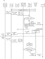
- FIG. 3 is a transmission manner of a multicast service data packet in a mobile network according to the present application.
- STB1, STB2, and STB3 are three terminal devices that request IPTV live broadcast program 1 (ie, the first multicast service) - a TV set-top box, in which STB1 is connected to CPE1, STB2 is connected to CPE2, and STB3 is connected to CPE3.
- CPE1, CPE2, and CPE3 are three independent customer premises equipments that access the mobile network through the RAN equipment.
- STB1 and CPE1 STB1 is the second terminal device, and CPE1 is the first terminal device; for STB2 and CPE2, STB2 is the second terminal device, and CPE2 is the first terminal device; for STB3 and CPE3 STB3 is the second terminal device, and CPE3 is the first terminal device.
- the gateway device and the CPE1, the CPE2, and the CPE3 respectively establish three logical transmission channels for transmitting data packets of the multicast service, and the logical transmission channel may be, for example, an evolved packet system bearer (EPS bearer) or a protocol data unit ( Protocol data unit (PDU) session.
- EPS bearer evolved packet system bearer
- PDU Protocol data unit
- the multicast service data packet will be mapped to the QoS flow by the gateway device and sent to the RAN device.
- the gateway device receives the data packet of the first multicast service, it needs to copy the data packet to the RAN device through the EPS bearer of the CPE 1, CPE2, CPE3 or the QoS flow of the PDU session, and the RAN device receives the data packet.
- the data packets of the three first multicast services are respectively mapped to the respective radio bearers (RBs) of the three customer premises equipments and sent to CPE1, CPE2, and CPE3, and the first group that CPE1, CPE2, and CPE3 will receive.
- the data packets of the broadcast service are sent to STB1, STB2 and STB3 respectively.
- the gateway device and the access network device use multicast transmission, and the access network device and the terminal device use unicast transmission.
- the gateway device For the transmission mode, if a plurality of terminal devices served by one RAN device request the first multicast service, and the gateway device receives the data packet of the first multicast service, the gateway device only needs to send a first message to the RAN device.
- the data packet of the multicast service is then transmitted by the RAN device according to the number of the first multicast service terminal device in the cell to which it is served, and then sent to each terminal device requesting the first multicast service.
- the gateway device When the gateway device sends the data packet of the first multicast service to the access network device in a multicast manner, the following two implementation options are available:
- a multicast transmission channel is established between the gateway device and the access network device, and one multicast transmission channel corresponds to one multicast service.
- the multicast transmission channel is a logical channel.
- the gateway device is a UPF
- a multicast transmission tunnel is established between the UPF and the RAN device (for example, a multicast N3 tunnel, that is, a GTP tunnel of the user plane of the N3 interface).
- each multicast transmission tunnel corresponds to a multicast service
- the gateway device in the 4G network architecture, the gateway device is a PGW/SGW/LGW, and a multicast transmission tunnel is established between the gateway device and the RAN device (for example, multicast S1)
- a tunnel that is, a GTP-U tunnel on the S1 interface
- each multicast transmission tunnel corresponds to one multicast service.
- the gateway device in the MBMS network architecture, the gateway device is an MBMS GW, and a multicast transmission is established between the gateway device and the RAN device.
- a tunnel for example, a multicast M1 tunnel, that is, a GTP-U tunnel on the M1 interface
- each multicast M1 tunnel corresponds to one multicast service.
- FIG. 4 is a transmission manner of a multicast service data packet in a mobile network according to the present application.
- STB 1 and STB2 are two TV set-top boxes that request IPTV live broadcast program 1 (first multicast service), and STB3 is a TV set-top box that requests IPTV live broadcast program 2 (second multicast service), where STB1 is connected to CPE1, and STB2 is connected to CPE2, STB3 is connected to CPE3.
- CPE1, CPE2, and CPE3 are three independent customer premises equipments that access the mobile network through the RAN equipment.
- STB1 is the second terminal device, and CPE1 is the first terminal device; for STB2 and CPE2, STB2 is the second terminal device, and CPE2 is the first terminal device; for STB3 and CPE3 STB3 is the second terminal device, and CPE3 is the first terminal device.
- Two multicast logical transmission channels corresponding to the first multicast service and the second multicast service are established between the gateway device and the RAN device, and the multicast logical transmission channel may be a user plane transmission of the N3/S1/M1 interface.
- the tunnel for example, the first multicast service corresponds to the multicast N3 tunnel 1, and the second multicast service corresponds to the multicast N3 tunnel 2.
- the gateway device When the gateway device receives the data packet of the first multicast service, the data packet is sent to the RAN device through the multicast N3 tunnel 1, and then the RAN device copies the data packet of the first multicast service into two, respectively.
- the packets mapped to the air interface between the RAN device and the user premises equipment are sent to CPE1 and CPE2, and CPE1 and CPE2 respectively send the received data packets of the first multicast service to STB1 and STB2.
- the gateway device receives the data packet of the second multicast service, the data packet needs to be sent to the RAN device through the multicast N3 tunnel 2, and then the RAN device maps the data packet of the second multicast service to the RAN device.
- the RB between the CPE and the CPE3 is sent to the CPE3.
- a multicast transmission channel is established between the gateway device and the access network device, and a multicast transmission channel can be used to transmit multiple multicast services.
- the gateway device is a UPF
- a multicast transmission tunnel is established between the UPF and the RAN device (for example, a multicast N3 tunnel, that is, a GTP-U tunnel of the N3 interface), and one multicast transmission tunnel corresponds to multiple groups.
- the gateway device is a PGW, and a multicast transmission tunnel is established between the PGW and the RAN device (for example, a multicast S1 tunnel, that is, a GTP-U tunnel of the S1 interface), and a multicast transmission tunnel corresponds to
- the gateway device is a MBMS GW, and a multicast transmission tunnel is established between the MBMS GW and the RAN device (for example, a multicast M1 tunnel, that is, a GTP-U tunnel of the S1 interface).
- a multicast transmission tunnel corresponds to multiple multicast services.
- the data packet sent by the gateway device to the RAN device needs to carry the identifier corresponding to the multicast service, and the RAN device can distinguish the data packets of different multicast services according to the identifier corresponding to the multicast service, and then the RAN.
- the device separately sends a corresponding multicast service data packet to the terminal device that requests each multicast service.
- FIG. 5 is a transmission manner of a multicast service data packet in a mobile network according to the present application.
- STB 1 and STB2 are two TV set-top boxes that request IPTV live broadcast program 1 (first multicast service)
- STB3 is a TV set-top box that requests IPTV live broadcast program 2 (second multicast service)
- STB1 is connected to CPE1
- STB2 is connected to CPE2
- STB3 is connected to CPE3.
- CPE1, CPE2, and CPE3 are three independent customer premises equipments that access the mobile network through the RAN equipment.
- a multicast logical transmission channel is configured between the gateway device and the RAN device for transmitting the first multicast service and the second multicast service, where the multicast logical transmission channel can be a user plane transmission of the N3/S1/M1 interface. Tunnel, such as the multicast N3 tunnel 1 in the figure.
- the gateway device When the gateway device receives the data packet of the first multicast service, the data packet is sent to the RAN device through the multicast N3 tunnel 1, and the RAN device identifies the data according to the identifier corresponding to the first multicast service carried in the data packet.
- the packet is the data packet of the first multicast service, and the RAN device maps the data packet of the first multicast service to the RB of the RAN device and the CPE1, and the RB of the RAN device and the CPE2, respectively, to the CPE1 and the CPE1, the CPE1 and the The CPE2 then sends the received data packets of the first multicast service to STB1 and STB2, respectively.
- the gateway device when the gateway device receives the data packet of the second multicast service, the data packet needs to be sent to the RAN device through the multicast N3 tunnel 1, and then the RAN device maps the data packet of the second multicast service to the RAN device.
- the RB between the CPE and the CPE3 is sent to the CPE3.
- the gateway device and the access network device use multicast transmission, and the access network device and the terminal device use multicast transmission.
- the corresponding description of the multicast transmission between the gateway device and the access network device can be understood by referring to the content of the second sending mode.
- the third transmission mode can further save air interface transmission resources compared to the second transmission mode.
- the transmission mode if a plurality of terminal devices served by one RAN device request the first multicast service, and the gateway device receives the data packet of the first multicast service, the gateway device only needs to send a packet to the RAN device.
- a data packet of the multicast service, and the RAN device can configure a unified air interface scheduling identifier for the terminal device that requests the first multicast service, where the unified air interface scheduling identifier corresponds to the first multicast service, and the RAN device sets the first group.
- the data packet of the broadcast service is sent to the terminal device requesting the first multicast service by using the unified air interface scheduling identifier.
- FIG. 6 is a transmission manner of a multicast service data packet in a mobile network according to the present application.
- STB 1 and STB2 are two TV set-top boxes that request IPTV live broadcast program 1 (first multicast service), and STB3 is a TV set-top box that requests IPTV live broadcast program 2 (second multicast service), where STB1 is connected to CPE1, and STB2 is connected to CPE2, STB3 is connected to CPE3.
- CPE1, CPE2, and CPE3 are three independent customer premises equipments that access the mobile network through the RAN equipment.
- STB1 is the second terminal device, and CPE1 is the first terminal device; for STB2 and CPE2, STB2 is the second terminal device, and CPE2 is the first terminal device; for STB3 and CPE3 STB3 is the second terminal device, and CPE3 is the first terminal device.
- the gateway device and the RAN device adopt a multicast transmission mode similar to that in FIG.
- the RAN device passes the In the air interface multicast mode, the data packet of the first multicast service is sent to the CPE1 and the CPE2, and the data packets of the first multicast service received by the CPE1 and the CPE2 are sent to the STB1 and the STB2, respectively.
- the RAN device maps the second multicast service data packet to the RB on the RB between the RAN device and the CPE 3. For the CPE3, or the RAN device can also send the second multicast service data packet to the CPE3 by means of air interface multicast.
- the RAN device sends a data packet to the terminal device by means of air interface multicasting, including, for example, the RAN device allocates an air interface scheduling identifier 1 corresponding to the first multicast service to the terminal devices (CPE1 and CPE2) requesting the first multicast service, Assigning, to the terminal device (CPE3) requesting the second multicast service, an air interface scheduling identifier 2 corresponding to the second multicast service, and then transmitting the data packet of the first multicast service to the requesting first multicast by using the air interface scheduling identifier 1
- the terminal device of the service sends the data packet of the second multicast service to the terminal device requesting the second multicast service by using the air interface scheduling identifier 2.
- the management device with the multicast service management function can determine the first multicast service data packet in the gateway device and the RAN device according to the network level multicast member table. And the sending manner of the first multicast service data packet between the RAN device and the terminal device; the management device sends the first configuration information to the gateway device, where the first configuration The information includes: indication information indicating a manner in which the first multicast service data packet is sent between the gateway device and the RAN device; the management device sends the second configuration information to the RAN device, where the second configuration information includes The first indication information indicating the manner in which the first multicast service data packet is sent between the gateway device and the RAN device.
- the second configuration information further includes, to indicate that the first multicast service data packet is in the RAN device.
- the indication information used to indicate a manner in which the first multicast service data packet is sent between the gateway device and the RAN device may be included in the management device to the gateway device and/or in an implicit manner. Or the information sent by the RAN device, for example, if the management device sends the information (for example, the first configuration information or the second configuration information) to the gateway device and/or the RAN device, the terminal device-specific transmission channel is included.
- the information means that the gateway device will send the first multicast service data packet to the RAN device in a unicast manner, or if the information transmitted by the management device to the gateway device and/or the RAN device includes multicast transmission
- the channel information means that the gateway device will send the first multicast service data packet to the RAN device in a multicast manner.
- the SMF is a management device with a multicast service management function
- the network-level multicast member table maintained by the SMF includes the first multicast service corresponding to the first multicast service, and the SMF determines the gateway device UPF.
- the method of sending the first multicast service data packet to the RAN device is multicast or unicast (for example, in the network level multicast member table maintained by the SMF, there are N terminal devices requesting the first multicast service, for the N There are M access network devices served by the terminal device, and M ⁇ N, the SMF determines that the UPF sends the first multicast service data packet to the RAN device in a multicast manner, and then the SMF sends the first configuration information to the UPF, which includes Instructing the UPF to send the indication information of the first multicast service data packet manner to the RAN device; optionally, the SMF further determines that the manner in which the RAN device sends the first multicast service data packet to the terminal device is unicast or multicast, and then the SMF Transmitting, to the RAN device, the second configuration information, where the first indication information is used to indicate that the UPF sends the first multicast service data packet manner to the RAN device, and optionally, The second indication information of the multicast service packet mode.
- the SMF sends the second configuration information to the RAN device, which may be sent by the SMF to the RAN device via the AMF, or sent by the SMF to the RAN device via the UPF.
- the indication information used to indicate that the UPF sends the first multicast service data packet manner to the RAN device may be included in the information sent by the SMF to the UPF and/or the RAN device in an implicit manner, for example, the SMF direction
- the first configuration information sent by the UPF, and/or the second configuration information sent by the SMF to the RAN device includes the first terminal device-specific transmission channel information (unicast tunnel identifier), which means that the UPF will be unicast.
- the identifier indicates that the UPF will send the data packet of the first multicast service to the RAN device in a multicast manner.
- the UPF determines that the method for sending the first multicast service data packet to the RAN device is multicast or unicast (for example, in the network level multicast member table maintained by the UPF, the terminal device requesting the first multicast service has N, there are M access network devices serving the N terminal devices, M ⁇ N, the UPF determines to send the first multicast service data packet to the RAN device in a multicast manner, and the UPF sends a second message to the RAN device.
- the configuration information includes first indication information for instructing the UPF to send the first multicast service data packet manner to the RAN device.
- the UPF further determines that the RAN device sends the first multicast service data packet to the terminal device in a manner of unicast or multicast, and includes, in the second configuration information that is sent to the RAN device, the RAN device to the terminal device. Sending the second indication information of the first multicast service data packet mode.
- the second configuration information is directly sent by the UPF to the RAN device, or sent by the SMF to the SMF, and then sent by the SMF to the RAN device via the AMF.
- the indication information used to indicate that the UPF sends the first multicast service data packet manner to the RAN device may be included in the information sent by the SMF to the RAN device in an implicit manner, for example, the SMF sends the information to the RAN device.
- the second configuration information includes the first terminal device-specific transmission channel information (unicast tunnel identifier), that is, the UPF will send the data packet of the first multicast service to the RAN device in a unicast manner; or, the SMF direction
- the second configuration information sent by the RAN device includes the multicast transmission channel information (multicast tunnel identifier), which means that the UPF will send the data packet of the first multicast service to the RAN device in a multicast manner.
- the UPF is both a management device with a multicast service management function and a gateway device that sends a data packet to the RAN device. Therefore, the management device does not need to send a control device to the gateway device to instruct the UPF to send the first multicast service to the RAN device.
- the step of the first configuration information of the packet mode is not required.
- the PGW determines that the method for sending the first multicast service data packet to the RAN device is multicast or unicast (for example, in the network level multicast member table maintained by the PGW, the terminal device requesting the first multicast service has N, there are M access network devices serving the N terminal devices, M ⁇ N, the PGW determines to send the first multicast service data packet to the RAN device in a multicast manner, and the PGW sends a second message to the RAN device.
- the method for sending the first multicast service data packet to the RAN device is multicast or unicast (for example, in the network level multicast member table maintained by the PGW, the terminal device requesting the first multicast service has N, there are M access network devices serving the N terminal devices, M ⁇ N, the PGW determines to send the first multicast service data packet to the RAN device in a multicast manner, and the PGW sends a second message to the RAN device.
- the configuration information includes first indication information for indicating a manner in which the PGW sends the first multicast service data packet to the RAN device.
- the PGW further determines that the RAN device sends the first multicast service data packet to the terminal device in a manner of unicast or multicast, and includes, in the second configuration information that is sent to the RAN device, the RAN device to the terminal device. Sending the second indication information of the first multicast service data packet mode.
- the second configuration information is sent by the PGW to the RAN device directly or via the SGW, or sent by the PGW to the MME, and then sent by the MME to the RAN device.
- the indication information used to indicate that the PGW sends the first multicast service data packet manner to the RAN device may be included in the information sent by the PGW to the RAN device in an implicit manner, for example, the PGW sends the information to the RAN device.
- the second configuration information includes the first terminal device-specific transmission channel information (unicast tunnel identifier), that is, the PGW will send the data packet of the first multicast service to the RAN device in a unicast manner; or, the PGW direction
- the second configuration information sent by the RAN device includes the multicast transmission channel information (multicast tunnel identifier), which means that the PGW will send the data packet of the first multicast service to the RAN device in a multicast manner.
- the PGW is both a management device with a multicast service management function and a gateway device that sends a data packet to the RAN device, so that the management device does not need to send the gateway device to indicate that the PGW sends the first multicast to the RAN device.
- the step of the first configuration information of the service packet mode is not a management device with a multicast service management function and a gateway device that sends a data packet to the RAN device, so that the management device does not need to send the gateway device to indicate that the PGW sends the first multicast to the RAN device.
- the MBMS GW is a management device with a multicast service management function
- the network-level multicast member table maintained by the MBMS GW includes the first multicast service corresponding to the first multicast service, because the MBMS GW At the same time, it is a gateway device, and the MBMS GW determines that the method for sending the first multicast service data packet to the RAN device is multicast or unicast (for example, the network-level multicast member table maintained by the MBMS GW requests the first multicast.
- the MBMS GW determines to send the first multicast service data packet to the RAN device in multicast mode.
- the GW sends the second configuration information to the RAN device, where the first indication information for indicating that the MBMS GW sends the first multicast service data packet manner to the RAN device is included.
- the MBMS GW further determines that the RAN device sends the first multicast service data packet to the terminal device in a manner of unicast or multicast, and includes, in the second configuration information that is sent to the RAN device, the RAN device to the terminal.
- the device sends the second indication information of the first multicast service data packet mode.
- the second configuration information is directly sent by the MBMS GW to the RAN device, or sent by the MBMS GW to the MME, and then sent by the MME to the RAN device, or sent by the MME to the RAN device via the MCE.
- the indication information used to indicate that the MBMS GW sends the first multicast service data packet manner to the RAN device may be included in an information that is sent by the MBMS GW to the RAN device in an implicit manner, for example, the MBMS GW to the RAN
- the second configuration information sent by the device includes the first terminal device-specific transmission channel information (unicast tunnel identifier), that is, the MBMS GW sends the data packet of the first multicast service to the RAN device in a unicast manner;
- the second configuration information that is sent by the MBMS GW to the RAN device includes the multicast transmission channel information (multicast tunnel identifier), that is, the MBMS GW sends the data of the first multicast service to the RAN device
- the RAN device itself may determine to send the first terminal device.
- a way of multicasting service packets The RAN device determines that the RAN device sends the first multicast service data to the terminal device according to the number of the terminal devices that request the first multicast service, and/or the link state between the terminal device and the RAN device that requests the first multicast service. The way the package is.
- the first multicast service data packet represents a data packet of the first multicast service.
- FIG. 7 is a schematic flowchart of a method 200 for transmitting a multicast service according to the present application in a 5G network architecture.
- the management device having the multicast service management function is a session management function (SMF), and the gateway device is a user plane function (UPF).
- SMF session management function
- UPF user plane function
- the method 200 includes the following.
- Step 201 The first terminal device sends a session establishment/modification request message to the access management function (AMF) through the access network device, and is used to trigger the process of establishing or modifying the PDU session.
- AMF access management function
- the session establishment/modification request message includes indication information, where the indication information is used to indicate that the PDU session requested by the first terminal device needs to support the multicast service, where the first terminal device may be, for example, a user station.
- Equipment CPE Equipment CPE
- home gateway mobile phone and other equipment.
- the indication information is a display indication.
- an indication bit is set, and when the indication bit is 1, the PDU session indicating that the request is established includes a multicast service, and when the indication bit is 0, the request is established.
- the multicast service is not included in the PDU session.
- the indication information may also be an implicit indication.
- a specific PDU session indicating the establishment of the report is identified by a specific access point name (APN) or data network name (DNN) or network slice identifier (slice ID) or slice type. It is necessary to support the multicast service, for example, if the APN/DNN is IPTV, or the slice ID indicates that the wireless broadband (WBB)/(wireless to the x, WTTx) corresponds to the network slice, indicating that the request is established/modified. Multicast services need to be supported in the PDU session.
- APN access point name
- DNN data network name
- slice ID indicates that the wireless broadband (WBB)/(wireless to the x, WTTx) corresponds to the network slice, indicating that the request is established/modified.
- WBB wireless broadband
- WTTx wireless broadband
- the AMF needs to select the SMF supporting the multicast service according to the multicast service indication information in the session establishment/modification request of the first terminal device, for example, a multicast SMF (multicast SMF, m- SMF); correspondingly, the SMF also needs to select a policy control function supporting the multicast service according to the indication information displayed or implicitly included in the message (for example, SM request) of the session establishment/modification request of the first terminal device sent by the AMF.
- a multicast SMF multicast SMF, m- SMF
- the SMF also needs to select a policy control function supporting the multicast service according to the indication information displayed or implicitly included in the message (for example, SM request) of the session establishment/modification request of the first terminal device sent by the AMF.
- the module contorl function establishes a PDU-CAN session; if dynamic policy and charging control (PCC) is configured, the SMF obtains PCC rules from the PCF, or the SMF obtains PCC rules according to static PCC rules; SMF selection
- the UPF that supports the multicast service for example, the multicast UPF (m-UPF) establishes the N4 session.
- the SMF selects the UPF the information such as the access point name APN/DNN and the UE location may also be referred to.
- the SMF can provide the quality of service (QoS) management and configuration function of the multicast service according to the content of the obtained PCC rules, including: acquiring the multicast service related
- the QoS parameters corresponding to the QoS flows are assigned a QoS flow identity (QFI) for the QoS flow of the multicast service; and a QoS phase configuration for the gateway device (for example, UPF), including An SDF template (for example, a multicast SDF template) of the multicast service, where the SDF template includes at least one packet filter for the multicast service data packet, which can guide the UPF to map the multicast service data packet to an appropriate one.
- QFI QoS flow identity
- UPF for example, UPF
- the QoS flow is sent, wherein the QoS related configuration of the SMF to the UPF can be carried by the request/response/transport message of the N4 interface; the SMF provides QoS configuration information (QoS profile) information for the RAN device, which includes the required Multicast service related QoS parameter configuration, such as QFI related to multicast service and corresponding QoS parameters, where SMF can pass through AMF to RAN device (via N11) Interface port and N2) transmitting the QoS configuration description.
- QoS configuration information QoS profile information
- the RAN device which includes the required Multicast service related QoS parameter configuration, such as QFI related to multicast service and corresponding QoS parameters, where SMF can pass through AMF to RAN device (via N11) Interface port and N2) transmitting the QoS configuration description.
- the first terminal device sends a session establishment/modification request message to the AMF through the access network device, which may be triggered by the multicast service session connection indication, and specifically includes the following manners:
- the second terminal device sends a first report message to the first terminal device, where the first terminal device considers the first report message as a multicast service session connection indication, and the first report message may be that the second terminal device requests to receive the multicast service Messages such as messages or access requests, for example, the second terminal device is an STB, the first terminal device is a CPE, and the first report message sent by the STB to the CPE is an access request or an address allocation request (such as DHCP discover) or a multicast service.
- the second terminal device is an STB
- the first terminal device is a CPE
- the first report message sent by the STB to the CPE is an access request or an address allocation request (such as DHCP discover) or a multicast service.
- the request (for example, an IGMP report message), after receiving the first report message, the CPE regards it as a multicast service session connection indication, and the process of triggering the establishment or modification of the PDU session by the RAN device sending a session establishment/modification request message to the AMF ;or
- the first terminal device obtains the multicast service session connection indication according to the service request of the application layer, for example, the first terminal device supports the multicast service, and if the application layer service request of the first terminal device corresponds to the multicast service, the first terminal The device considers the service request of the application layer as a multicast service session connection indication, and the process of triggering the establishment or modification of the PDU session by the RAN device sending a session establishment/modification request message to the AMF; or
- the first terminal device obtains the multicast service session connection indication according to the service-related information in the pre-configuration information.
- the first terminal device is a CPE, and the CPE can statically configure service-related information, or the CPE obtains management from the TR-069 server.
- Operation configuration information including service-related information, or the UE policy obtained by the CPE from the PCF includes service-related information, and if the service-related information indicates that the CPE-supported service includes a multicast-type service (for example, a CPE configuration)
- the CPE can view the information related to the service as a multicast service session connection indication, and send a session establishment/modification request message to the AMF through the RAN device to trigger establishment or modification of the PDU session. the process of.
- the second terminal device may include a terminal device that can support the multicast service, such as a set top box STB, an internet television, a mobile phone, and a computer.
- a terminal device that can support the multicast service, such as a set top box STB, an internet television, a mobile phone, and a computer.
- a plurality of different terminal devices may be connected to the first terminal device, and then connected to the mobile network by using the first terminal device, the multiple different terminal devices and the first A local area network is formed between the terminal devices to form a service of the first terminal device.
- Step 202 The second terminal device sends a first report message to the first terminal device, where the first report message is a message that the second terminal device requests to receive the first multicast service, where the first report message includes the first multicast service. logo.
- the identifier corresponding to the first multicast service may be an IP address of the first multicast service, or a temporary mobile group identity assigned to the first multicast service. , TMGI), may also be the indication information indicating the first multicast service that is agreed in the communication system, for example, "1" indicates the first multicast service, and "2" indicates the second multicast service, It should be understood that the identifier corresponding to the first multicast service is not limited in this application, and the identifier corresponding to the first multicast service may also be other information.
- the second terminal device is the STB
- the first terminal device is the CPE.
- the first report message may be a report message that the STB requests to receive a certain multicast service.
- the device request is represented by the IGMP join report in the embodiment of the present invention.
- step 202 is an optional step. When the second terminal device has a multicast service requirement, step 202 is performed.
- the step 202 may be performed before the step 201, that is, the first report message sent by the second terminal device to the first terminal device may be regarded as a multicast service session connection indication by the first terminal device, as step 201.
- the first terminal device sends a trigger condition of the session establishment/modification request message to the AMF through the RAN device.
- Step 203 The first terminal device sends a second report message to the RAN device, where the second report message is used by the first terminal device to receive the first multicast service.
- the second report message is that the CPE requests to receive the IGMP Join report of the first multicast service, or the second report message is that the STB request forwarded by the CPE receives the IGMP join report of the first multicast service.
- the second report message carries an identifier corresponding to the first multicast service.
- the second report message may further carry an identifier of the second terminal device, and/or an identifier corresponding to the first terminal device.
- the first terminal device requests to receive the first multicast service, where the second terminal device has the first multicast service requirement, and the first terminal device forwards the message that the second terminal device requests to receive the first multicast service, or
- a terminal device is configured to receive the first multicast service by requesting the IGMP proxy capability.
- the first terminal device itself has a first multicast service request, and requests to receive the first multicast service.
- the first terminal device is configured to configure the IGMP proxy capability, and the second multicast service is requested to be received, and the second report message carries the identifier corresponding to the first terminal device as an example. .
- the identifier corresponding to the first terminal device includes, but is not limited to, at least one of the following information: an identifier of the first terminal device, a connection session identifier established by the first terminal device, a bearer identifier of the first terminal device, and a The session identifier of a terminal device or the bearer corresponding to the bearer, the identifier of the RAN device serving the first terminal device (eg, RAN device IP address, eNB/gNB ID, global eNB/gNB ID, etc.), the cell serving the first terminal device
- the identifier of the first terminal device may be, for example, an IP address of a first terminal device, a medium access control (MAC) address, an international mobile subscriber identity (IMSI), International mobile station equipment identity (IMEI), temporary mobile subscriber identity (TMSI), cell radio network temporary identifier (C-RNTI), terminal equipment access UE identity on the network and core network interfaces (eg NG interface, S1 interface, etc.)
- the first terminal device records information that the second terminal device requests to receive the first multicast service, including, for example, the first terminal device maintains a local multicast member table, where the local area device
- the multicast member table includes at least one identifier corresponding to a certain multicast service, and/or an information entry corresponding to the multicast service, where the information entry corresponding to the multicast service includes And an identifier corresponding to the second terminal device that requests to receive the multicast service.
- the first terminal device reads the received first report message, and learns that the second terminal device requests to receive the first multicast service.
- the local multicast member table saved by the first terminal device has been saved and the first multicast If the valid information entry of the second terminal device of the service is not required, the local multicast member table does not need to be updated. Otherwise, the first terminal device adds a corresponding multicast service to the local multicast member table maintained by the first terminal device.
- the information item of the second terminal device, or the local multicast member table of the second terminal device is modified, so that the information item of the second terminal device corresponding to the first multicast service is valid, and the first multicast service corresponds to the first
- the information entry of the second terminal device includes an identifier corresponding to the first multicast service, and/or an identifier corresponding to the second terminal device requesting to receive the first multicast service.
- Table 1 shows the form of the local area multicast member table maintained by the first terminal device, the first column is the identifier corresponding to the multicast service, the second column is the identifier of the second terminal device, and the third column is Whether the information entry corresponding to each row is valid (this column is optional). If the first report message indicates that the terminal device UE 03 requests to receive the IGMP join report of the first multicast service corresponding to the program 1 address, the first terminal device is in the information entry corresponding to the program 1 address in the local area multicast member table.
- the identifier of the terminal device UE 03 is added , and the value of the column "Effective" of the information item corresponding to the UE 03 is set to 1 (0 means that the line information is invalid, and 1 means that the line information is valid).
- the identifier corresponding to the multicast service includes, for example, a multicast IP address corresponding to the multicast service or a temporary mobility group identifier TMGI or other information that identifies the multicast service that is agreed in the communication system.
- the multicast service corresponding to the identifier corresponding to the multicast service may be understood as “the multicast service receivable by the first terminal device. Or, it can also be understood as "the multicast service that the first terminal device has joined.”
- Table 1 Form of the local multicast member table maintained by the first terminal device
- the identifier corresponding to the first multicast service is a multicast IP address corresponding to the first multicast service, for example, 224.0.1.0.
- the identifier corresponding to the second terminal device includes, but is not limited to, at least one of the following information: an identifier of the second terminal device, an interface/port identifier between the second terminal device and the first terminal device, and a second terminal A bearer or logical channel identifier between the device and the first terminal device, and the like.
- the identifier of the second terminal device may be an IP address, a MAC address, an IMSI, a TMSI, a C-RNTI, and the like of the second terminal device.
- the first terminal device can maintain the local area multicast member table by configuring an IGMP/MLD proxy (IGMP/MLD proxy) function or an IGMP/MLD Snooping (IGMP/MLD snooping) function.
- IGMP/MLD proxy for example, the group member report, the IGMP join report, or the leaving report, the IGMP leave report
- the first terminal device may record the request for the multicast service.
- the second terminal device identifier (for example, the IP address or MAC address of the second terminal device) or the port number of the IGMP/MLD packet received, and/or the identifier corresponding to the multicast service requested by the second terminal device (such as multicast IP address).
- the first terminal device when the first terminal device is configured with the IGMP/MLD proxy, the first terminal device can read the information in the IGMP/MLD packet of the terminal device, maintain the local multicast member table composed of the second terminal device, and serve as the IGMP.
- the MLD client sends IGMP/MLD messages (including the active report and the query response). If the first terminal device is configured with IGMP/MLD Snooping, the first terminal device can listen to the information in the packet.
- a local multicast member table formed by the second terminal device and forwards each received IGMP/MLD packet to the access network device.
- the first terminal device determines, according to the received first report message, whether to send the second report message to the RAN device, including, for example, the first terminal device sends the first report message to the access network device.
- Sending a second report message or, the first terminal device receives the first report message, if the first terminal device does not send the second report message for requesting to receive the first multicast service within a preset time period,
- a terminal device sends a second report message to the access network device; or, after receiving the first report message, the first terminal device checks the local multicast member table maintained by the first terminal device, if the first report message does not include the If the identifier of the first multicast service, or all the valid information entries of the local multicast member table, does not correspond to the identifier corresponding to the first multicast service, the first terminal device sends the identifier to the access network device.
- the second report message is used to request to receive the first multicast service, and the second report message includes an identifier corresponding to the first multicast service.
- Step 204 The RAN device sends a message requesting to receive the first multicast service to a management device (for example, an SMF) having a multicast service management function.
- a management device for example, an SMF
- the specific process includes: the RAN device receives the second report message sent by the first terminal device, and forwards the second report message to the gateway device (for example, the UPF), where the UPF identifies the second report message as the first After the message related to the multicast service sent by the terminal device, the message is sent to the management device (for example, SMF) having the multicast service management function, where the second report message is included.
- the gateway device for example, the UPF
- the management device for example, SMF having the multicast service management function
- the SMF needs to configure the detection rule of the multicast service related message to the UPF.
- the UPF identifies the second report message after receiving the second report message.
- the first terminal device is related to the multicast service (such as an IGMP join report or an IGMP leave report), and forwards the second report message to the SMF, so that the SMF performs network level multicast member management.
- the detection rule of the SMF configuration is to determine that the received data packet is an IGMP report message according to the format of the IGMP report message and the padding content of the corresponding field.
- the UPF identifies that the second report message is a multicast service-related message sent by the first terminal device, and includes, for example, the source IP address and the destination IP address of the second report message read by the UPF, and/or, The IGMP message content, where the source address is the IP address of the first terminal device, and the destination IP address is the first multicast service address.
- the IGMP type field is displayed as the member report type, and the IGMP group address field is the first multicast service address.
- the UPF may determine that the second report message is an IGMP report message sent by the first terminal device for requesting to receive the first multicast service, or an IGMP join report, or the source IP address and destination IP address of the second report message read by the UPF.
- the UPF can determine that the second report message is the IGMP sent by the first terminal device for requesting to receive the first multicast service. Report message - IGMP join report.
- the RAN device may send the second report message to the SMF through the AMF.
- the first terminal device carries the second report message by using a non-access stratum (NAS) message, and the RAN device forwards the NAS message to the AMF corresponding to the first terminal device after receiving the message. And forwarding, by the AMF, the key information in the second report message or the second report message carried in the NAS message to the SMF.
- NAS non-access stratum
- the manner in which the first terminal device carries the second report message by using the NAS message includes, for example, the first terminal device carrying the message in a NAS message sent by the first terminal device by using a message container (message container) a second report message; or the NAS message sent by the first terminal device is a specific type (for example, a type related to a multicast service request), and includes information carried in the second report message, for example, any of the following One or more items: an identifier corresponding to the first terminal device, an identifier corresponding to the first multicast service, an indication for requesting to receive the first multicast service, and the like.
- the RAN device has a multicast service management capability, that is, the RAN device can maintain a cell-level multicast member table according to the received second report message (for example, the RAN device configures an IGMP proxy or an IGMP snooping function, and can read the first terminal.
- the IGMP join report or IGMP leave report sent by the device maintains the cell-level multicast member table.
- the cell-level multicast member table includes a first multicast service identifier, and/or an identifier corresponding to a terminal device (including the first terminal device) that requests the first multicast service served by the RAN device
- the second terminal device identifier is further included.
- Table 2 shows a form of a cell-level multicast member table maintained by the RAN device, where the first column is an identifier corresponding to the multicast service (for example, a multicast IP address), and the second column is the first terminal.
- the third column is a radio bearer identifier used by the RAN device and the first terminal device to send a corresponding multicast service data packet, and the fourth list indicates whether each row of information entries is valid (this column is optional). If the second report message is an IGMP join report indicating that the first terminal device UE 13 requests to receive the multicast service corresponding to the program 1 address, the RAN is in the first terminal device identifier corresponding to the program 1 address in the cell-level multicast member table.
- Table 2 Cell-level multicast member table format maintained by the RAN device
- link state information may also be included.
- the link state information may be used by the RAN device to determine a manner of sending the first multicast service data packet to the first terminal device.
- Step 205 The SMF determines, according to the second report message, whether the UPF of the first multicast service providing the first terminal device has established a connection with the network device about the first multicast service.
- the SMF reads the first multicast service address in the second report message, and determines whether the UPF of the first multicast service providing the first service of the first terminal device has established a first multicast service with the network device. connection. For example, the SMF may check the network level multicast member table. If the at least one valid information item related to the first multicast service is included, the SMF may determine that the UPF has established a connection with the network device regarding the first multicast service, otherwise the SMF It can be determined that the UPF has not established a connection with the network device regarding the first multicast service.
- the network device may be, for example, a router or a gateway, a multicast query node, a multicast service server, and the like that support IP multicast in the data network DN.
- the network level multicast member table, and the contents of the valid information items related to the first multicast service, can be understood by referring to the description in step 208.
- Step 205 is an optional step.
- Step 206 The SMF sends a first notification message to the UPF, where the first notification message is used to instruct the UPF to establish a connection with the network device about the first multicast service.
- the SMF determines whether the UPF of the first multicast service providing the first terminal device has established a connection with the network device for the first multicast service; if the determination is no, the SMF The UPF sends a first notification message, indicating that the UPF establishes a connection with the network device about the first multicast service; if the determination is yes, step 206 and step 207 may not be performed.
- Step 207 The UPF sends a first request message to the network device, where the first request message is used by the UPF request to establish a connection with the network device about the first multicast service.
- the UPF can use a multicast routing protocol such as IGMP/MLD or a multicast routing protocol (PIM) to send the first multicast service to the network device (for example, send an IGMP join report). Or the request message of the first multicast service corresponding multicast routing tree (for example, the UPF sends a graft request message to join the multicast routing tree).
- a multicast routing protocol such as IGMP/MLD or a multicast routing protocol (PIM) to send the first multicast service to the network device (for example, send an IGMP join report).
- PIM multicast routing protocol
- step 208 the SMF maintains a network level multicast member table.
- the network-level multicast member table maintained by the SMF includes an identifier corresponding to each multicast service, and corresponding to each multicast service, and an information item related to the terminal device that needs to receive the multicast service, where the information is received.
- the terminal device of this multicast service such as the first terminal device, is regarded as one of the members of this multicast service.
- the information entry includes an identifier corresponding to the terminal device that is a member of the multicast service, and the identifier can be understood by referring to the “identity corresponding to the first terminal device” introduced in step 203.
- the SMF maintains the network level multicast member table, and may include, for example, the SMF reads the first multicast service identifier in the second report message, and the identifier corresponding to the first terminal device, optionally, the SMF may also read The identifier of the second terminal device in the second report message. If the network-level multicast member table maintained by the SMF has a valid information entry corresponding to the first terminal device and the first multicast service, the network-level multicast member table does not need to be updated; otherwise, the SMF pairs the network-level multicast member table.
- the update is performed, that is, the SMF adds the information entry corresponding to the first terminal device and the first multicast service in the network level multicast member table, or the information item corresponding to the first terminal device and the first multicast service takes effect.
- the information item corresponding to the first multicast service includes the identifier corresponding to the first multicast service, and/or the identifier corresponding to the first terminal device, and optionally, the second terminal The identity of the device.
- the SMF sends a network level multicast member notification message to the UPF, so that the UPF knows that the first terminal device is added to the member corresponding to the first multicast service.
- the UPF receives the data packet of the first multicast service, the data packet is sent to all the terminal devices that request the first multicast service content corresponding to the first multicast service identifier in the network level multicast member table.
- the first terminal device forwards.
- the network level multicast member notification message may include an updated network level multicast member table, or all valid information items corresponding to the first multicast service in the updated network level multicast member table, or used to indicate The indication information of the first terminal device and the information item corresponding to the first multicast service is added.
- Table 3 shows a form of a network-level multicast member table maintained by a management device (such as SMF), the first column is an identifier corresponding to the multicast service, and the second column is the access network device. The third column is the identifier of the terminal device.
- a management device such as SMF
- the second report message is an IGMP join report indicating that the terminal device UE 22 requests to receive the program 1 address corresponding to the multicast service
- the access network device RAN 2 serves the UE 22 , and in the network level multicast member table in Table 3 If there is no information item corresponding to the terminal device UE 22 and the program 1 address, the SMF adds the identifier of the terminal device UE 22 and/or to the UE 22 in the information item corresponding to the program 1 address in the network level multicast member table.
- the access network device identifies RAN 2 .
- the identifier of the RAN device may be, for example, an IP address of the RAN device, a tunnel end identity (TEID) configured at the RAN device, a base station identifier (eNB/gNB ID), and a global base station identifier (global eNB) /gNB ID) and so on.
- TEID tunnel end identity
- eNB/gNB ID base station identifier
- global eNB global base station identifier
- Table 3 A network-level multicast member table format maintained by the management device
- Table 4 shows another form of network level multicast member table, the first column is the identifier corresponding to the multicast service, the second column is the identifier of the access network device, and the third column is the terminal device.
- the fourth example is whether the corresponding information item of each line is valid. If the second report message requests the terminal device UE 21 to join the program 1 address and the access network RAN 2 serves the UE 21 , the SMF corresponding to the UE in the information entry corresponding to the program 1 address in the network level multicast member table The value of the column "Information is valid" of 21 is set to 1 (0 means that the line information is invalid, 1 means the line information is valid).
- Table 4 A network-level multicast member table format maintained by the management device
- the SMF adds the terminal device to the information entry corresponding to the program 1 address in the network level multicast member table.
- the UE 22 and its corresponding access network device identity RAN 2 are identified and the value in the "Is valid" column is set to one.
- step 205 to step 208 the SMF guides the UPF to establish a multicast connection according to the second report message, and maintains a specific implementation process of the network level multicast member table.
- the network level multicast member table may be first maintained.
- the SMF determines, according to the second report message, whether the UPF that provides the first multicast service of the first terminal device has established a first multicast service with the network device. Connection, this process can refer to step 205. If the SMF determines that the UPF does not establish a connection with the network device for the first multicast service, the SMF sends a first notification message to the UPF, where the first notification message is used to instruct the UPF to establish a first multicast with the network device.
- this process can refer to step 206.
- the UPF After receiving the first notification message, the UPF sends a first request message to the network device, where the first request message is used by the UPF request to establish a connection with the network device about the first multicast service, and the process may refer to step 207. . That is, the above step 208 may be performed before the above steps 205-207, or in another alternative, step 208 is performed before step 206-step 207.
- the SMF first maintains the network level multicast member table or determines whether the UPF that provides the first multicast service of the first terminal device has established a connection with the network device for the first multicast service. Not limited.
- step 209 the SMF sends a notification message to the RAN device.
- the notification message includes a cell-level multicast member notification message, where the cell-level multicast member notification message includes a first multicast service identifier, and/or, with the first multicast service member The identifier corresponding to all the terminal devices of the RAN device service; or the cell-level multicast member notification message includes: indication information for indicating that the first terminal device is added to the first multicast service member, the first terminal The device is served by the RAN device.
- the SMF determines that the first multicast service data packet is sent between the gateway device and the RAN device in a unicast mode or a multicast mode (in this embodiment, the unicast mode), and the SMF further sends the second configuration to the RAN device.
- the second configuration information includes first indication information for indicating that the UPF sends the first multicast service data packet manner to the RAN device.
- the notification message sent by the SMF to the RAN device includes the second configuration information.
- the first indication information is implicitly included in a message sent by the SMF to the RAN device, for example, in a process of establishing a PDU session supporting the multicast service between the first terminal device and the network
- the message sent by the SMF to the RAN device via the AMF includes the first terminal device-specific transmission tunnel identifier, indicating that the manner in which the first multicast service data packet is sent between the UPF and the RAN device is unicast; or the SMF is sent to the RAN via the AMF.
- the message of the device includes the multicast transmission tunnel identifier, which indicates that the first multicast service data packet is sent between the UPF and the RAN device.
- the SMF may send the notification message to the RAN device through the AMF; or, in another possible example, the SMF sends the notification message to the RAN device through the UPF.
- Step 209 is an optional step that needs to be performed in some cases, for example, when the multicast service data packet is transmitted in the multicast mode between the UPF and the RAN device, and the RAN device does not have the multicast service management capability described in step 204. Step 209 is performed. When the multicast service data packet is sent in the unicast mode between the UPF and the RAN device (or the terminal device), or the RAN device has the multicast service management capability described in step 204, step 209 may not be performed.
- Step 210 The network device sends the first multicast service data packet to the UPF.
- the first multicast service data packet is a data packet of the first multicast service.
- Step 211 The UPF receives the first multicast service data packet sent by the network device, and copies the first multicast service data packet.
- the UPF copies the first multicast service data packet, including: the UPF determines, according to the network level multicast member notification message sent by the SMF, which of the terminal devices of the UPF service is the first one.
- the multicast service member then replicates the packet according to the number of first multicast members.
- the UPF may further add an identifier corresponding to the terminal device and/or information related to QoS guarantee in the copied data packet.
- the network-level multicast member information maintained by the SMF is as shown in Table 3.
- the first multicast service corresponds to the program 1, and the members thereof include the UE 11 , the UE 12 , and the UE 21.
- the UPF After receiving the data packet of the program 1, the UPF According to the network level multicast member notification message sent by the SMF, the data packet is copied into three copies, and the copied data packet is sent to the UE 11 , the UE 12 , and the UE 21 respectively .
- the UPF may add one or more of the following information in the copied data packet: an identifier of the QoS flow to which the first multicast service data packet is mapped (eg, QoS flow identity, QFI), corresponding to 5G QoS identifier (5QI), N3 tunnel identifier corresponding to the PDU session of the terminal device.
- an identifier of the QoS flow to which the first multicast service data packet is mapped eg, QoS flow identity, QFI
- 5QI 5G QoS identifier
- N3 tunnel identifier corresponding to the PDU session of the terminal device.
- Step 212 The UPF sends the first multicast service data packet to the RAN device.
- the UPF maps the copied first multicast service data packet to the first QoS flow according to the QoS-related configuration provided by the SMF (for example, the multicast service flow template multicast SDF template), and sends the first multicast service data packet to the RAN device.
- the RAN device serves the first terminal device, and the first terminal device is one of members of the first multicast service.
- Step 213 The RAN device receives the first multicast service data packet sent by the UPF, and sends the first multicast service data packet to the first terminal device.
- the RAN device receives the first multicast service data packet sent by the UPF, and sends the first multicast service data packet to the first terminal device, including, for example, the first multicast service data packet received by the RAN device, carrying and An identifier corresponding to a terminal device (for example, an N3 tunnel identifier corresponding to the first terminal device PDU session), so the RAN device may determine that the first multicast service data packet needs to be sent to the first terminal device, optionally, the RAN
- the device is configured according to the first QFI carried in the first multicast service data packet, the QoS parameter corresponding to the first QFI, and/or the first QoS flow and the air interface radio bearer (RB) represented by the first QFI.
- RB air interface radio bearer
- the corresponding relationship is to map the data packet to the RB and send it to the first terminal device.
- the correspondence between the QoS flow and the RB may be configured in advance by the management device (for example, SMF) to the RAN device, or may be determined by the RAN device according to the QoS flow and the QoS parameters of the RB.
- Step 214 The first terminal device receives the first multicast service data packet sent by the RAN device, and sends the first multicast service data packet to the second terminal device. It should be understood that the first device sends the first multicast service data packet to the second terminal device as an optional action. If the first terminal device receives the first report message for requesting to receive the first multicast service, the first terminal device further needs to send the first group to the second terminal device in this step. Broadcast service packets.
- the first multicast service data packet received by the first terminal device carries the first multicast service identifier, and the first terminal device queries the local multicast member table maintained by the first terminal device to determine the second The terminal device is a member of the first multicast service, and then the first terminal device sends the first multicast service data packet to the second terminal device.
- Step 215 The second terminal device sends a third report message to the first terminal device, to request to end the first multicast service.
- the first multicast service is corresponding to the first multicast service
- the third report message includes an identifier corresponding to the first multicast service.
- the third report message is an IGMP leave report sent by the second terminal to leave the first multicast service, where the IP address of the second terminal device is included, and/or the IP address of the first multicast service.
- the first terminal device reads or listens to the third report message, and learns that the second terminal device requests to end the first multicast service, where the first terminal device records the information that the second terminal device requests to end the first multicast service.
- the first terminal device records the information that the second terminal device requests to end the first multicast service, and includes, for example, the first terminal device deletes the first multicast service identifier in the local multicast member table maintained by the first terminal device.
- the information entry of the second terminal device, or the first terminal device modifies the local multicast member table maintained by the first terminal device, so that the information entry of the second terminal device corresponding to the first multicast service identifier is invalid; and the first multicast service
- the content of the information item identifying the corresponding second terminal device can be referred to the description in step 202.
- the first terminal device sends the query information to confirm whether there are other members of the first multicast service in the local area network served by the first terminal device.
- the first terminal device sends the query information to confirm whether there are other members of the first multicast service, including, for example, the first terminal device sends an IGMP/MLD query message, for querying the local area network service served by the first terminal device, And the terminal device that needs to receive the first multicast service, if the first terminal device does not receive the report message that the terminal device in the local area network requests to receive the first multicast service within a set time after sending the query information, A terminal device may consider that there is no need for the terminal device to access the first multicast service in the local area network of the service, and may send a report message requesting to quit the first multicast service to the access network device in a subsequent step.
- Step 215 is an optional step.
- the second terminal device supports the active sending of the IGMP/MLD Leave message
- the second terminal device is connected to the first terminal device and needs to end the first multicast service.
- Step 216 The first terminal device sends a fourth report message to the RAN device, where the fourth report message is used by the first terminal device to request to exit the first multicast service.
- the first terminal device is a CPE
- the fourth report message is a request sent by the CPE to end the IGMP leave report of the first multicast service (IGMP leave report); or the fourth report message is a request sent by the STB to exit the first multicast service.
- the IGMP Leave report is sent to the RAN device via the CPE.
- the fourth report message carries an identifier corresponding to the first multicast service.
- the fourth report message may further carry the identifier of the second terminal device, and/or with the first terminal device. Corresponding identifier.
- the identifier corresponding to the first terminal device may refer to the description in the foregoing steps.
- the first terminal device requests to quit the first multicast service, and the second terminal device requests to quit the first multicast service, and the first terminal device forwards the request for the second terminal device to quit the first multicast service, or the first
- the terminal device configures the IGMP proxy capability to request to quit the first multicast service; or the first terminal device requests to quit the first multicast service.
- the first terminal device is configured with the IGMP proxy capability, and the first multicast service is requested to be taken as an example to introduce the solution.
- Step 217 The RAN device sends a message requesting to end the first multicast service to a management device (for example, an SMF) having a multicast service management function.
- a management device for example, an SMF
- the RAN device sends a message to the SMF to end the first multicast service, where the RAN device receives the fourth report message sent by the first terminal device, and forwards the message to the gateway device (for example, the UPF).
- the fourth report message after the UPF identifies the fourth report message as the first terminal device related to the multicast service (such as the IGMP join report or the IGMP leave report), sends a message to the SMF, where the fourth report message is included.
- the SMF needs to configure a detection rule of the multicast service related message to the UPF.
- the UPF identifies the fourth report message after receiving the fourth report message.
- the first terminal device forwards the message related to the multicast service, and forwards the fourth report message to the SMF, so that the SMF performs multicast member management.
- the detection rule of the SMF configuration is to determine that the received data packet is an IGMP report message according to the format of the IGMP report message and the padding content of the corresponding field.
- the UPF identifies that the fourth report message is a message related to the multicast service of the first terminal device, and includes, for example, a source IP address and a destination IP address of the fourth report message read by the UPF, and/or an IGMP report.
- the source address is the IP address of the first terminal device
- the destination IP address is 224.0.0.2 (special group address, which refers to all multicast routers in the network segment).
- the IGMP type field is displayed as the "leave group message" type, IGMP.
- the UPF may determine that the fourth report message is an IGMP report message that the first terminal device requests to quit the first multicast service, or an IGMP leave report; or, the UPF reads the fourth report.
- the source IP address and the destination IP address of the message where the source address is the IP address of the first terminal device, and the destination IP address is 224.0.0.2, the UPF can determine that the fourth report message is the first terminal device requesting to quit the first multicast service.
- the RAN device sends a message requesting to end the first multicast service to the SMF, including: the RAN sends the fourth report message to the SMF by using the AMF.
- the first terminal device passes the non-access stratum (the NAS message carries the fourth report message, and after receiving the RAN device, the RAN device forwards the NAS message to the AMF corresponding to the first terminal device, and then the AMF will And the key information in the fourth report message or the fourth report message that is carried in the NAS message is forwarded to the SMF, where the first terminal device carries the fourth report message by using the NAS message,
- the first terminal device carries the fourth report message through a message container in the NAS message sent by the first terminal device; or the NAS message sent by the first terminal device is of a specific type ( For example, the type related to the multicast service request, where the information carried in the fourth report message is included, for example, any one or any of the following: an identifier corresponding to the first terminal device
- the RAN device has a multicast service management capability, that is, the RAN device can maintain the cell-level multicast member table according to the received fourth report message.
- the RAN device configures the IGMP snooping function, and maintains the cell-level multicast member table as shown in Table 2.
- the RAN device reads the fourth report message sent by the first terminal device (UE 13 ) to request the UE 13 to leave the first multicast service.
- the RAN device may in its cell-level multicast membership table maintained, the UE deleting the program information items 13 corresponding to 1, the UE 13 or the program information item corresponding to the 1
- the value of the four columns "Is it valid" is set to 0, indicating that this row information is invalid.
- Step 218 The SMF maintains a network level multicast member table according to the fourth report message.
- the network level multicast member table maintained by the SMF can be understood by referring to the description in step 208.
- the SMF maintains the network level multicast member table, and may include, for example, the SMF reads the first multicast service identifier included in the fourth report message, and the identifier corresponding to the first terminal device, optionally,
- the fourth report message further includes an identifier of the second terminal device;
- the SMF updates the network level multicast member table, that is, deletes the information entry corresponding to the first terminal device and the first multicast service in the network level multicast member table. Or invalidating the information item corresponding to the first terminal device and the first multicast service.
- the information item corresponding to the first multicast service includes the identifier corresponding to the first multicast service, and/or the identifier corresponding to the first terminal device, and optionally, the second terminal The identity of the device.
- the network level multicast member table maintained by the SMF is as shown in Table 3. If the fourth report message is that the terminal device UE 21 requests to end the message of the program 1, the SMF deletes the corresponding address of the program 1 in the network level multicast member table.
- the information item of the terminal device UE 21 includes the identifier of the access network device RAN 2 ; or the network level multicast member table maintained by the SMF is as shown in Table 4, if the fourth report message is the terminal device UE 21 Requesting to end the message of program 1, and the access network RAN 2 serves the UE 21 , and the SMF sets the "valid" column in the information item of the terminal device UE 21 corresponding to the program 1 address in the network level multicast member table as 0, indicating that this line of information is invalid.
- the network level multicast member notification message needs to be sent to the UPF, so that the UPF knows that the member corresponding to the first multicast service should be The first terminal device is removed, so that when the UPF receives the data packet of the first multicast service, it is no longer sent to the first terminal device.
- the network level multicast member notification message may include an updated network level multicast member table, or all valid information items corresponding to the first multicast service in the updated network level multicast member table, or used to indicate The indication information of the first terminal device and the information item corresponding to the first multicast service is deleted.
- step 219 the SMF determines whether there is a member of the first multicast service in the network it serves.
- the SMF determines whether there is a member of the first multicast service in the network it serves, including, for example, the SMF reads the first multicast service address in the fourth report message, and the SMF checks the updated network level multicast member table. If there is no valid information item related to the first multicast service, it may be considered that there is no member of the first multicast service.
- the SMF may also send an inquiry message to confirm whether there is a member of the first multicast service in the terminal device that is served, and specifically includes, for example, the SMF sends an IGMP/MLD query message, and is used to query whether the network it serves is in the network.
- the query message may be sent by the SMF to the terminal device through the AMF and the RAN device, or by the SMF through the UPF and
- the RAN device sends the report message to the terminal device, and after receiving the query message, if the first multicast service demand or other multicast service demand is received, the terminal device sends a report message indicating the service requirement to the SMF, and sends the report message to the SMF.
- the process can refer to step 202 - step 204.
- the SMF can update the network-level multicast member table maintained by the SMF according to any report message sent by any terminal device indicating the first multicast service requirement or any multicast service requirement. If the SMF does not receive any report message requesting the terminal device to receive the first multicast service within a set time after sending the inquiry information, the SMF may consider that there is no member of the first multicast service in the network it serves.
- Step 220 The SMF sends a second notification message to the UPF, where the second notification message is used to instruct the UPF to disconnect the first multicast established by the network device.
- the SMF determines whether there is a member of the first multicast service in the network it serves. If the determination is no, the SMF sends a second notification message to the UPF, indicating that the UPF and the network device remove the first group. Broadcast service connection.
- Step 221 The UPF sends a second request message to the network device, where the second request message is used by the UPF to request the network device to disconnect the first multicast.
- the UPF may use a multicast management protocol such as IGMP/MLD or a multicast routing protocol such as PIM to send a network device to leave the first multicast service (for example, send an IGMP leave report) or leave the multicast corresponding to the first multicast service.
- a request message for the routing tree (for example, the UPF sends a pruning request message leaving the multicast routing tree).
- the network device includes, for example, a multicast router in a data network, or a query node, or a multicast server.
- Steps 220 and 221 are optional steps.
- the result of step 219 is performed when the SMF determines that the terminal device served by the SMF does not have a member of the first multicast service.
- step 218 to step 221 the SMF instructs the UPF to remove the multicast connection according to the fourth report message, and maintains a specific implementation process of the network level multicast member table.
- the SMF processes the report message of the terminal device, maintains the network level multicast member table, and guides the gateway device UPF to maintain the multicast connection to the network device, and the UPF receives the multicast service data packet from the network device, It performs replication and sends multicast service data packets to the terminal device via the RAN device in unicast mode according to the QoS rules configured by the SMF, so that the terminal device can obtain the multicast service through the wireless network.
- FIG. 8 is a schematic flowchart of a method 300 for transmitting a multicast service according to the present application in a 5G network architecture.
- the management device with the multicast service management function and the gateway device that provides the multicast service transmission service for the terminal device are the same device, that is, the user plane function (UPF).
- UPF user plane function
- Steps 301 to 303 are the same as steps 201 to 203 in the method 200, and can be understood by referring to the corresponding description, and details are not described herein.
- Step 304 The RAN device sends a message requesting to receive the first multicast service to the management device (such as the UPF in the embodiment of the present application) that has the multicast service management function.
- the management device such as the UPF in the embodiment of the present application
- the RAN device sends a message requesting to receive the first multicast service to the UPF, where the RAN device receives the second report message sent by the first terminal device, and then connects the interface between the RAN device and the UPF.
- the second report message is sent directly to the UPF (eg, an N3 interface).
- the first terminal device sends the second report message to the RAN device by using the user plane data packet, and the RAN device may directly send the second report to the UPF via the N3 tunnel between the first terminal device and the UPF.
- User plane packet that reports the message.
- the RAN device sends a message requesting to receive the first multicast service to the UPF, where the RAN device receives the second report message sent by the first terminal device, and then sends the message to the AMF via, for example, an N2 interface.
- the AMF sends the second report message to the SMF via, for example, an N11 interface
- the SMF sends the second report message to the UPF via, for example, an N4 interface.
- the RAN device sends the second report message carried in the NAS to the SMF through the AMF, and then the second report is sent by the SMF.
- the message is sent to the UPF through the N4 interface message.
- the manner in which the first terminal device carries the second report message by using the NAS message may be understood by referring to the related description in step 204 of the method 200.
- the second report message may be identified as a message that the first terminal device requests to receive the first multicast service, for example, the source IP address of the second report message read by the UPF and The destination IP address, where the source address is the first terminal device IP address, and the destination IP address is the first multicast service address, the UPF can determine that the second report message is sent by the first terminal device to request to receive the first multicast service.
- the RAN device has a multicast service management capability, that is, the RAN device can maintain a cell-level multicast member table according to the received second report message (for example, the RAN device configures an IGMP proxy or an IGMP snooping function, and can read the first terminal.
- the IGMP join report or IGMP leave report sent by the device maintains the cell-level multicast member table.
- the cell-level multicast member table includes a first multicast service identifier, and/or an identifier corresponding to a terminal device (including the first terminal device) that requests the first multicast service served by the RAN device
- the second terminal device identifier is further included.
- Step 305 The UPF receives the second report message, and determines whether a connection with the network device is established for the first multicast service.
- the UPF reads the first multicast service address in the second report message, and the first terminal device identifier, and determines whether the UPF of the first multicast service of the first terminal device provides the transmission service and the network device. A connection is established about the first multicast service.
- the UPF that provides the service for the first multicast service of the first terminal device and the UPF that receives the second report message are the same UPF or different UPFs. If the two are different UPFs, the two are The N9 interface may be used to indicate that the UPF and the network device establish or remove the indication information about the first multicast connection and the corresponding response information. To simplify the description, in the embodiment of the present application, the two are mainly the same UPF. The example is introduced.
- the UPF may check the network level multicast member table maintained by the UPF, and if it contains at least one valid information item related to the first multicast service, the UPF is considered to have established a first with the network device. The connection of the multicast service. Otherwise, it is considered that the UPF has not established a connection with the network device regarding the first multicast service.
- the content of the network level multicast member table and the valid information items related to the first multicast service refer to the description of step 307.
- Step 306 The UPF sends a first request message to the network device, where the first request message is used by the UPF to establish a connection with the network device about the first multicast service.
- the UPF may use a multicast management protocol such as IGMP/MLD or a multicast routing protocol such as PIM to send a network device to join the first multicast service (for example, send an IGMP join) or join the first multicast service corresponding group.
- a request message for a broadcast tree for example, a graft request message sent to join a multicast routing tree).
- Step 306 is an optional step, and in step 305, the UPF determines that the connection with the network device has not been established with respect to the first multicast.
- step 307 the UPF maintains a network level multicast member table.
- the network-level multicast member table maintained by the UPF includes an identifier corresponding to each multicast service, and corresponding to each multicast service, and an information item related to the terminal device that needs to receive the multicast service, where the information is received.
- the terminal device of this multicast service such as the first terminal device, is regarded as one of the members of this multicast service.
- the information entry includes an identifier corresponding to the terminal device that is a member of the multicast service, and the identifier can be understood by referring to the “identity corresponding to the first terminal device” introduced in step 203.
- the UPF maintains the network level multicast member table, and may include, for example, the first multicast service identifier in the second report message read by the UPF, and the identifier corresponding to the first terminal device, optionally, the UPF may also read The identifier of the second terminal device in the second report message.
- the network-level multicast member table maintained by the UPF already has a valid information entry corresponding to the first terminal device and the first multicast service, the network-level multicast member table does not need to be updated; otherwise, the UPF-to-network-level multicast member table The update is performed, that is, the UPF adds the information entry corresponding to the first terminal device and the first multicast service in the network level multicast member table, or the information item corresponding to the first terminal device and the first multicast service takes effect.
- the information item corresponding to the first multicast service includes the identifier corresponding to the first multicast service, and/or the identifier corresponding to the first terminal device, and optionally, the second terminal The identity of the device.
- the form of the network level multicast member table maintained by the UPF can be understood by referring to Table 3 and Table 4 in step 208 of the method 200 and the corresponding description, and details are not described herein.
- Steps 305 to 307 are specific implementation processes for the UPF to establish a multicast connection according to the second report message and maintain the network level multicast member table.
- the network level multicast member table may be first maintained.
- the UPF determines, according to the second report message, whether the UPF that provides the first multicast service of the first terminal device has established a first multicast service with the network device. Connection, this process can refer to step 305. If the UPF determines that the connection to the first multicast service is not established with the network device, the UPF sends a first request message to the network device, where the first request message is used by the UPF request to establish a first For the connection of the multicast service, refer to step 306 for this process.
- the above step 307 can be performed before the above steps 305-306. Whether the UPF maintains the network-level multicast member table first or whether the UPF that provides the transmission service for the first multicast service of the first terminal device has established a connection with the network device for the first multicast service. Not limited.
- Step 308 the UPF sends a notification message to the RAN device.
- the notification message includes a cell-level multicast member notification message, where the cell-level multicast member notification message includes a first multicast service identifier, and/or, with the first multicast service member The identifier corresponding to all the terminal devices of the RAN device service; or the cell-level multicast member notification message includes: indication information for indicating that the first terminal device is added to the first multicast service member, the first terminal The device is served by the RAN device.
- the UPF may send the notification message directly to the RAN device, or the UPF first sends the notification message to the SMF, and then sent by the SMF to the RAN device via the AMF.
- the UPF determines that the first multicast service data packet is sent between the gateway device and the RAN device in a unicast mode or a multicast mode (in this embodiment, the unicast mode), and the UPF further sends the second configuration to the RAN device.
- the second configuration information includes first indication information for indicating that the UPF sends the first multicast service data packet manner to the RAN device.
- the notification message sent by the SMF to the RAN device includes the second configuration information.
- the first indication information is implicitly included in a message sent by the UPF to the SMF, and is further included in a message sent by the SMF to the RAN device, for example, established between the first terminal device and the network.
- the message sent by the SMF to the RAN device via the AMF includes the transmission tunnel identifier specific to the first terminal device, indicating the manner in which the first multicast service data packet is sent between the UPF and the RAN device. If the message sent to the RAN device by the SMF includes the multicast transmission tunnel identifier, the manner in which the first multicast service data packet is sent between the UPF and the RAN device is multicast.
- Step 308 is an optional step that needs to be performed in some cases, for example, when the multicast service data packet is transmitted in the multicast mode between the UPF and the RAN device, and the RAN device does not have the multicast service management capability described in step 304. Step 308 is performed. When the multicast service data packet is sent in the unicast mode between the UPF and the RAN device (or the terminal device), or the RAN device has the multicast service management capability described in step 304, step 308 may not be performed.
- Step 309 The network device sends the first multicast service data packet to the UPF.
- Step 310 The UPF receives the first multicast service data packet sent by the network device, and copies the first multicast service data packet.
- the UPF copies the first multicast service data packet, including: the UPF queries the network level multicast member table, and learns which terminal devices in the UPF are members of the first multicast service, and then The data packet is copied according to the number of the first multicast members.
- the UPF may also add an identifier corresponding to the terminal device and/or information related to the QoS guarantee in the copied data packet.
- the network-level multicast member information maintained by the UPF is as shown in Table 3.
- the first multicast service corresponds to the program 1, and the members thereof include the UE 11 , the UE 12 , and the UE 21.
- the UPF After receiving the data packet of the program 1, the UPF According to the network level multicast member table, the data packet needs to be copied 3 times, and the copied data packet will be sent to the UE 11 , the UE 12 , and the UE 21 respectively .
- the UPF may add one or more of the following information in the copied data packet: an identifier of the QoS flow to which the first multicast service data packet is mapped (eg, qos flow identity, QFI), and the terminal Indicates the N3 tunnel ID of the PDU session of the device.
- an identifier of the QoS flow to which the first multicast service data packet is mapped eg, qos flow identity, QFI
- the terminal Indicates the N3 tunnel ID of the PDU session of the device.
- Steps 311 to 315 can be understood by referring to the description of step 212 to step 216 in the method 200, and details are not described in this embodiment.
- the RAN device sends a message requesting to end the first multicast service to the management device (for example, the UPF in this embodiment) having the multicast service management function.
- the management device for example, the UPF in this embodiment
- the RAN device sends a message requesting to end the first multicast service to the UPF, where the RAN device receives the fourth report message sent by the first terminal device, and then passes the interface between the RAN device and the UPF (for example, the N3 interface) forwards the fourth report message directly to the UPF.
- the first terminal device sends the fourth report message to the RAN device by using the user plane data packet, and the RAN device may directly send the fourth report to the UPF via the N3 tunnel between the first terminal device and the UPF.
- User plane packet that reports the message.
- the RAN device sends a message requesting to end the first multicast service to the UPF, where the RAN device receives the fourth report message sent by the first terminal device, and then sends the message to the AMF via, for example, an N2 interface.
- the fourth report message the AMF sends the fourth report message to the SMF via, for example, an N11 interface, and then the SMF sends the fourth report message to the UPF via, for example, an N4 interface.
- the RAN device sends the fourth report message carried in the NAS to the SMF through the AMF, and then the fourth report is sent by the SMF.
- the message is sent to the UPF through the N4 interface message.
- the manner in which the first terminal device carries the fourth report message by using the NAS message may be understood by referring to the related description in step 217 of the method 200.
- the fourth report message may be identified as a message that the first terminal device requests to end the first multicast service, for example, the source IP address of the fourth report message read by the UPF and Destination IP address, and/or IGMP packet content, where the source address is the IP address of the first terminal device, and the destination IP address is 224.0.0.2 (special group address, which refers to all multicast routers in the network segment), IGMP type field
- the IGMP group address field is the first multicast service address, and the UPF can determine that the fourth report message is the first terminal device requesting to quit the IGMP report message of the first multicast service.
- the UPF reads the source IP address and the destination IP address of the fourth report message, where the source address is the IP address of the first terminal device, and the destination IP address is 224.0.0.2, the UPF can determine that the fourth report message is the first The terminal device requests to quit the IGMP report message of the first multicast service, the IGMP leave report.
- Step 317 The UPF maintains a network level multicast member table according to the fourth report message.
- the content contained in the network-level multicast member table maintained by the UPF can be understood by referring to the description in step 307.
- the UPF maintains the network level multicast member table according to the fourth report message, and may include, for example, the first multicast service identifier in the fourth report message read by the UPF, and the identifier corresponding to the first terminal device, optionally, the UPF
- the identifier of the second terminal device in the fourth report message may also be read; the UPF updates the network level multicast member table, that is, the information corresponding to the first terminal device and the first multicast service is deleted in the network level multicast member table.
- the information item corresponding to the first multicast service includes the identifier corresponding to the first multicast service, and/or the identifier corresponding to the first terminal device, and optionally, the second terminal The identity of the device.
- the network level multicast member table maintained by the UPF is as shown in Table 3. If the fourth report message is that the terminal device UE 21 requests to end the message of the program 1, the UPF deletes the corresponding address of the program 1 in the network level multicast member table.
- the information item of the terminal device UE 21 includes the identifier of the access network device RAN 2 ; or the network level multicast member table maintained by the UPF is as shown in Table 4, if the fourth report message is the terminal device UE 21 Requesting to end the message of program 1, and the access network RAN 2 serves the UE 21 , and the "failed" column in the information item of the terminal device UE 21 corresponding to the program 1 address in the network level multicast member table is set to 0, indicating that this line of information is invalid.
- the UPF when the multicast service data packet is sent in the multicast mode between the UPF and the RAN device, and the RAN device does not have the multicast service management capability described in step 304, if the UPF performs the network level multicast member table. Update, the UPF will send a cell-level multicast member notification message to the RAN device, so that the RAN device knows that the first terminal device should be removed from the member corresponding to the first multicast service, and the RAN device receives the first multicast service. When the packet is received, it will not be sent to the first terminal device.
- the cell-level multicast member notification message includes a first multicast service identifier, and/or an identifier corresponding to all terminal devices served by the RAN device in the first multicast service member; or the cell level
- the multicast member notification message includes indication information for indicating removal of the first terminal device in the first multicast service member, where the first terminal device is served by the RAN device.
- the cell-level multicast member notification message may be directly sent by the UPF to the RAN device, or sent by the SMF to the SMF, and then sent by the SMF to the RAN device via the AMF.
- step 318 the UPF determines whether there is a member of the first multicast service in the network it serves.
- the UPF determines whether there is a member of the first multicast service in the network it serves, including, for example, the UPF reads the first multicast service address in the fourth report message, and the UPF checks the updated network level multicast member table. If there is no valid information entry related to the first multicast service, it may be considered that there is no member of the first multicast service; optionally, the UPF may also send an inquiry message to confirm whether there is still a terminal device in the service.
- a member of the first multicast service specifically, for example, the UPF sends an IGMP/MLD query message, and is used to query whether the terminal device that needs to receive the first multicast service is in the network that serves the service, or whether there is any need to receive any group.
- the query message may be sent by the UPF to the terminal device through the RAN device, or sent by the UPF to the SMF and then sent to the terminal device via the AMF and the RAN device, after receiving the query message, if the terminal device receives the query message, If there is a first multicast service requirement or other multicast service requirements, a report message indicating the service requirement is returned to the UPF.
- the UPF can update the network-level multicast member table maintained by the received terminal according to the received report message indicating the first multicast service requirement or any multicast service requirement. If the UPF does not receive any report message requesting the first multicast service to be received by the terminal device within a set time after sending the inquiry information, the UPF may consider that there is no member of the first multicast service in the network it serves.
- Step 319 The UPF sends a second request message to the network device, where the second request message is used by the UPF to request the network device to disconnect the first multicast.
- the UPF may use a multicast management protocol such as IGMP/MLD or a multicast routing protocol such as PIM to send a network device to leave the first multicast service (for example, send an IGMP leave report) or leave the multicast corresponding to the first multicast service.
- a request message for the routing tree (for example, the UPF sends a pruning request message leaving the multicast routing tree).
- the network device includes, for example, a multicast router in a data network, or a query node, or a multicast server.
- Step 319 is an optional step.
- the result of step 318 is performed when the UPF determines that the terminal device served by the terminal does not have a member of the first multicast service.
- step 317 to step 319 the UPF maintains the network level multicast member table according to the fourth report message, and removes the specific implementation process of the first multicast connection.
- the method 300 differs from the method 200 in that, in the method 200, the management device that performs multicast service management is an SMF, and in the method 300, the management device that performs multicast service management is an UPF.
- the UPF processes the report message of the terminal device, maintains the network level multicast member table, and maintains the multicast connection to the network device, and the UPF receives the multicast service data packet from the network device, and copies the multicast service data packet.
- the RAN device sends the multicast service data packet to the terminal device in the unicast mode, so that the terminal device can obtain the multicast service through the wireless network.
- the gateway device and the access network device when the gateway device and the access network device send the multicast service data packet in the multicast mode, the gateway device and the access network device need to establish a first channel, where the first channel is used to transmit the multicast service. data pack.
- the following describes the first channel established between the gateway device and the access network device.
- FIG. 9 is a schematic flowchart of a method 400 for transmitting a multicast service according to the present application in a 5G network architecture.
- the management device with the group management function is an SMF and the gateway device is a UPF.
- the multicast service data packet is sent by the UPF and the RAN device in multicast mode.
- method 400 includes the following.
- Step 401 A management device (for example, a multicast-enabled SMF/PGW/MBMS GW) that performs multicast session management receives a message for triggering establishment of a multicast transmission channel, and then triggers a process of establishing a multicast transmission channel.
- a management device for example, a multicast-enabled SMF/PGW/MBMS GW
- the multicast transmission channel refers to a channel between the gateway device and the RAN device for transmitting a multicast service data packet (for example, a GTP-U tunnel for transmitting a multicast service data packet).
- a multicast service data packet for example, a GTP-U tunnel for transmitting a multicast service data packet.
- the gateway device is a UPF
- the RAN device is a gNB
- a multicast N3 tunnel is established between the UPF and the gNB
- the gateway device is a PGW
- the RAN device is an eNB
- a multicast S1 tunnel is established between the PGW and the eNB
- the gateway device is an MBMS GW
- the RAN device is an eNB
- a multicast M1 tunnel is established between the MBMS GW and the eNB.
- the manner in which the management device that triggers the management of the multicast session starts to establish the multicast transmission channel process includes but is not limited to the following three types:
- the message used to trigger the establishment of the multicast transmission channel may be, for example, a report message sent by the terminal device based on a multicast management protocol (such as IGMP/MLD protocol) for requesting to receive the first multicast service (for example, IGMP).
- Join report for example, the SMF receives an IGMP join report sent by the first terminal device for requesting to receive the first multicast service, selects a multicast-enabled UPF (multicast UPF, M-UPF), and triggers the UPF and the service.
- the session establishment/modification request message sent by the terminal device may include the multicast service indication information, for example, the session establishment/modification request message sent by the first terminal device to the AMF via the RAN device, including the multicast service indication information, indicating The first terminal device has a multicast service requirement, and the AMF sends a session establishment/modification request message of the first terminal device to the SMF, and the SMF according to the multicast service indication letter therein Selecting a multicast-enabled UPF, and triggering the establishment of a multicast N3 tunnel between the UPF and the RAN device serving the first terminal device.
- the access point name APN/DNN and the UE may also be
- the second is the triggering of network service configuration.
- the mobile network needs to establish a multicast transmission channel in advance according to the service configuration plan, which is used to trigger the establishment of the multicast transmission channel message, and may be multicast by the service management platform (for example, BM-SC) in the mobile network.
- the session management device for example, SMF/PGW/MBMS GW
- the third is the triggering of the multicast service platform.
- the multicast service request of the terminal device is sent to the multicast service platform (for example, the service request sent by the application layer protocol is invisible to the gateway device and the RAN device in the mobile network), and the multicast service platform is not available.
- the multicast service platform Located within the mobile network (eg, the multicast service platform is BMSC) or outside the mobile network (eg, in a data network), the multicast service platform can be to a device in the mobile network (eg, a service management device in the mobile network) The BMSC/PCRF, etc.
- the service management device in the mobile network sends a management device (for example, SMF/PGW/MBMS GW) for performing multicast session management to trigger the establishment of the multicast transmission channel.
- a management device for example, SMF/PGW/MBMS GW
- the message triggers the process of starting to establish a multicast transmission channel.
- the following steps 4011-4016 are based on the 5G network architecture as an example of establishing a multicast transmission channel.
- Step 4011 The SMF sends an N11 request message for establishing a multicast transmission channel to the AMF, where the request message includes configuration information of the multicast transmission channel, and the configuration information of the multicast transmission channel includes one or more of the following contents. : multicast tunnel endpoint identity (M-TEID), QoS parameter configuration corresponding to the multicast tunnel (including, for example, QFI corresponding to the multicast service, and/or corresponding 5G QoS identifier (5G QoS Identifier, 5QI) ), allocation and retention priority (ARP), guaranteed flow bit rate (GFBR) and other parameters, identifiers corresponding to multicast services, multicast source addresses, multicast bearer identifiers, etc. .
- M-TEID multicast tunnel endpoint identity
- QoS parameter configuration corresponding to the multicast tunnel including, for example, QFI corresponding to the multicast service, and/or corresponding 5G QoS identifier (5G QoS Identifier, 5QI)
- ARP allocation and retention priority
- the M-TEID corresponds to one multicast service, that is, different multicast services correspond to different multicast transmission channels; in another possible manner, the M-TEID and multiple When a multicast service packet is transmitted between the UPF and the RAN device, different multicast services are multiplexed into the same multicast transmission channel.
- the same M-TEID may be used, that is, different RAN devices configure the same M-TEID, or different RAN devices may be configured separately. M-TEID.
- the AMF receives the N2 request message for establishing the multicast transmission channel, stores the multicast transmission channel information contained therein, and forwards the request message for establishing the multicast transmission channel to the RAN device.
- Step 4013 The RAN device receives a request message for establishing a multicast transmission channel, and returns a multicast channel acknowledge response message or a multicast channel reject response message to the AMF.
- the RAN device If the RAN device accepts the multicast transmission channel configuration information included in the request message, and completes the multicast transmission channel configuration according to the configuration information, the RAN device returns a multicast channel acknowledgement response message to the AMF for the core network device. Indicates that the multicast transmission channel configuration of the RAN device is completed. Otherwise, the RAN device returns a multicast channel reject response message to the AMF, which is used to indicate to the core network device that the RAN device cannot establish a multicast transmission channel according to the multicast transmission channel configuration information.
- the RAN device may indicate, in the multicast channel reject response message, the reason that the multicast transmission channel cannot be established, for example, the M-TEID conflicts with other unicast TEIDs configured by the RAN device.
- Step 4014 The AMF receives the multicast channel acknowledge response message or the multicast channel reject response message sent by the RAN device, and forwards the message to the SMF.
- Step 4015 After the SMF receives the multicast channel acknowledgment response message, the SMF sends a session modification request to the UPF, where the configuration information of the multicast transmission channel is included.
- the configuration information of the multicast transmission channel refer to the corresponding step 4011. The content is understood; or, the SMF receives the multicast channel reject response message.
- the multicast channel fails to be established, and the process ends.
- the UPF will send the multicast service data packet to the terminal device in a unicast manner. For details, refer to the description of the method 200 or the method 300.
- the SMF receives the multicast channel reject response message, and the SMF checks the reason why the RAN device cannot establish the multicast transmission channel, and modifies the configuration information of the multicast transmission channel, and then performs step 4011.
- Step 4016 The UPF receives the session modification request sent by the SMF, saves the multicast transmission channel configuration information, completes the configuration of the multicast transmission channel, and then returns a session modification response message to the SMF to confirm the establishment of the multicast transmission channel. .
- step 401 the first terminal device has established a PDU session supporting the multicast service with the mobile network, but does not support multicast transmission between the network device and the RAN device.
- step 401 is performed in a process in which the first terminal device establishes a multicast PDU session with the mobile network; or, in another possible manner, step 401 is at the first terminal.
- the device and the mobile network are configured before the PDU session that supports the multicast service is established. For the process of establishing a PDU session for the first terminal device and the mobile network to support the multicast service, refer to the description of step 201 in the method 200.
- Step 402 The second terminal device sends a first report message to the first terminal device, where the first report message is a message that the second terminal device requests to receive the first multicast service, where the first report message includes the first multicast service.
- the first report message is a message that the second terminal device requests to receive the first multicast service, where the first report message includes the first multicast service.
- logo A detailed description of step 402 can be found in the description of step 202 in method 200.
- the identifier corresponding to the first multicast service may be an IP address of the first multicast service, or may be an indication information indicating the first multicast service that is agreed in the communication system, and The identifier of the first multicast transmission channel that is established, for example, using the first multicast transmission channel as the identifier of the first multicast service. It should be understood that the identifier corresponding to the first multicast service is not limited, and the identifier corresponding to the first multicast service may be other information.
- Step 402 is an optional step. When the second terminal device starts to request the multicast service, step 402 is performed.
- the step 402 may be performed before the step 401, and the first report message sent by the second terminal device to the first terminal device may be regarded as a multicast service session connection indication by the first terminal device, as step 401.
- the first terminal device sends a trigger condition of the session establishment/modification request message to the AMF through the RAN device.
- Steps 403 to 404 can be understood by referring to the description of step 203 to step 204 in the method 200, and details are not described herein.
- step 402-step 404 may be performed before step 401.
- the SMF requests the first terminal device sent by the RAN device to receive the message of the first multicast service, triggering to start establishing multicast.
- the transmission channel process corresponds to the first one of the three types of triggering modes described in step 401, that is, the management device that triggers the multicast session management triggered by the multicast service request of the terminal device starts to establish a multicast transmission channel process.
- Step 405 to step 407 reference may be made to the description of step 205 to step 207 in the method 200, and details are not described herein again.
- step 408 the SMF maintains a network level multicast member table.
- Step 408 can be understood by referring to the description of step 208 in the method 200.
- the SMF determines a sending manner of the first multicast service data packet between the gateway device and the RAN device, and the SMF sends the network level multicast member to the UPF.
- the first configuration information is sent to the UPF, where the first configuration information includes indication information indicating a manner in which the first multicast service data packet is sent between the gateway device and the RAN device.
- the manner in which the SMF sends the first configuration information to the UPF includes: in a possible manner, the SMF includes the first configuration information in the network level multicast member notification message and sends the information to the UPF; in another possible manner, the SMF The first configuration information is sent by the SMF to the UPF together with the network level multicast member notification message. In another possible manner, the first configuration information and the network level multicast member notification message are sent by the SMF respectively. To UPF.
- the SMF may first maintain the network level multicast member table, and then instruct the UPF to establish a connection with the network device about the first multicast service, that is, step 408 is performed before step 405, or step 408 is performed before step 406.
- step 409 the SMF sends a notification message to the RAN device.
- the notification message includes a cell-level multicast member notification message, where the cell-level multicast member notification message includes a first multicast service identifier, and/or, with the first multicast service member The identifier corresponding to all the terminal devices of the RAN device service; or the cell-level multicast member notification message includes: indication information for indicating that the first terminal device is added to the first multicast service member, the first terminal The device is served by the RAN device.
- the RAN device will maintain a cell-level multicast member table according to the cell-level multicast member notification message.
- the format and content of the cell-level multicast member table can be understood by referring to the corresponding description in step 404. If the RAN device has the multicast service management capability described in step 404, the SMF can be sent to the RAN device to send the cell-level multicast member notification message, which reduces signaling overhead and saves radio resources.
- the SMF determines a sending manner of the first multicast service data packet between the gateway device and the RAN device, and/or a sending manner of the multicast service data packet between the RAN device and the terminal device, and the SMF further sends the MME to the RAN.
- the device sends the second configuration information, where the second configuration information includes first indication information for indicating that the UPF sends the first multicast service data packet manner to the RAN device, and/or is used to instruct the RAN device to send the first information to the terminal device.
- a second indication information of a multicast service packet mode In a possible manner, the notification message sent by the SMF to the RAN device includes the second configuration information.
- the SMF may send the notification message to the RAN device through the AMF; or, in another possible example, the SMF sends the notification message to the RAN device through the UPF.
- Step 410 The network device sends the first multicast service data packet to the UPF.
- Step 411 The UPF receives the first multicast service data packet sent by the network device, and copies the first multicast service data packet.
- the UPF copies the first multicast service data packet, and the UPF learns, according to the network level multicast member notification message sent by the SMF, which of the terminal devices of the UPF service are members of the first multicast service, and/or The information of the RAN device serving the terminal device, and then the UPF copies the data packet according to the number of RAN devices serving the first multicast member.
- the UPF may add the following to the copied data packet.
- One or more of the information information related to QoS guarantee, an identifier corresponding to the RAN device, an identifier corresponding to the first multicast service, and the like.
- the multicast member information maintained by the SMF is as shown in Table 3.
- the first multicast service corresponds to the program 1, and the members thereof include the UE 11 , the UE 12 , and the UE 21.
- the RAN device serving the UE 11 and the UE 12 is RAN 1
- the RAN device serving the UE 21 is the RAN 2
- the UPF copies the data packet according to the network level multicast member notification message sent by the SMF, and the copied data is copied.
- the packets will be sent to RAN 1 and RAN 2 respectively .
- the UPF may add one or more of the following information in the copied data packet: QoS flow identity (QFI) to which the first multicast service data packet is mapped, UPF and RAN device
- QFI QoS flow identity
- the multicast tunnel identifier for example, the multicast transport tunnel identifier M-TEID corresponding to the multicast service between the UPF and the RAN device
- the identifier corresponding to the first multicast service for example, the first between the UPF and the RAN device corresponds to the first
- the multicast transmission tunnel identifier of the multicast service is M-TEID1, or other identifier that can be uniquely mapped to the first multicast service.
- Step 412 The UPF sends the first multicast service data packet to the RAN device.
- the UPF maps the copied first multicast service data packet to the appropriate QoS flow according to the QoS-related configuration provided by the SMF (for example, the multicast service flow template multicast SDF template), and sends the first multicast service data packet to the RAN device.
- the RAN device serves the first terminal device, and the first terminal device is one of members of the first multicast service.
- Step 413 The RAN device receives the first multicast service data packet sent by the UPF, and sends the first multicast service data packet to the first terminal device.
- the first multicast service data packet received by the RAN device carries an identifier corresponding to the first multicast service, and the RAN device determines, according to the identifier, that the data packet is the first multicast service.
- the data packet and according to the cell-level multicast member table maintained by the RAN device, knows which of the terminal devices served by the RAN device are members of the first multicast service. If the second configuration information sent by the SMF to the RAN device includes the second indication information indicating the manner in which the first multicast service data packet is transmitted between the RAN device and the terminal device, the RAN device may follow the foregoing.
- the second indication information determines that the air interface sending manner of the first multicast service data packet is unicast or multicast; or the RAN device according to the information contained in the cell level multicast member table maintained by the RAN device (for example, the terminal requesting the first multicast service)
- the number of devices, and/or the link quality information between the terminal devices and the RAN device determines whether the air interface sending mode of the first multicast service data packet is unicast or multicast.
- the RAN device determines to send the first multicast service data packet to the terminal device in the air interface unicast mode, the RAN device copies the received data packet of the first multicast service (for example, the RAN device according to the terminal device it serves)
- the number of the first multicast service members in the replication is transmitted to the terminal devices that are members of the first multicast service (including the first terminal device); or, if the RAN device determines to use the air interface multicast mode to the terminal device
- the RAN device can configure a unified air interface scheduling identifier for the terminal device, where the unified air interface scheduling identifier corresponds to the first multicast service, and the RAN device sends the data packet of the first multicast service.
- the unified air interface scheduling identifier is sent to the terminal devices (including the first terminal device) that are members of the first multicast service.
- Steps 414 to 417 are the same as steps 214 to 217 in the method 200, and can be understood by referring to the corresponding description, and details are not described herein.
- Step 418 The SMF maintains a network level multicast member table according to the fourth report message.
- the network level multicast member table maintained by the SMF can be understood by referring to the description in step 208 of the method 200.
- the SMF for example, the SMF reads the first multicast service identifier included in the fourth report message, and the identifier corresponding to the first terminal device
- the fourth report message further includes an identifier of the second terminal device
- the SMF updates the network level multicast member table, that is, in the network level multicast member table, deleting the first terminal device and the first multicast service corresponding to The information item, or the information item corresponding to the first terminal device and the first multicast service is invalidated.
- the information item corresponding to the first multicast service includes the identifier corresponding to the first multicast service, and/or the identifier corresponding to the first terminal device, and optionally, the second terminal The identity of the device.
- the network level multicast member table maintained by the SMF is as shown in Table 3. If the fourth report message is that the terminal device UE 21 requests to end the message of the program 1, the SMF deletes the corresponding address of the program 1 in the network level multicast member table.
- the information item of the terminal device UE 21 includes the identifier of the access network device RAN 2 ; or the network level multicast member table maintained by the SMF is as shown in Table 4, if the fourth report message is the terminal device UE 21 Requesting to end the message of program 1, and the access network RAN 2 serves the UE 21 , and the SMF sets the "valid" column in the information item of the terminal device UE 21 corresponding to the program 1 address in the network level multicast member table as 0, indicating that this line of information is invalid.
- the network level multicast member notification message needs to be sent to the UPF, so that the UPF knows that the member corresponding to the first multicast service should be The first terminal device is removed, so that when the UPF receives the data packet of the first multicast service, it is no longer sent to the first terminal device.
- the network level multicast member notification message may include an updated network level multicast member table, or all valid information items corresponding to the first multicast service in the updated network level multicast member table, or used to indicate The indication information of the first terminal device and the information item corresponding to the first multicast service is deleted.
- the SMF updates the network level multicast member table according to the fourth report message, and the SMF determines that the sending manner of the first multicast service data packet between the gateway device and the RAN device changes (for example, by multicast)
- the mode is changed to the unicast mode.
- the SMF sends the first configuration information to the UPF.
- For the content and the sending manner of the first configuration information refer to the description in step 408.
- the SMF when the RAN device does not have the multicast service management capability described in step 404, if the SMF updates the network level multicast member table according to the fourth report message, the SMF sends a cell level multicast member notification message to the RAN.
- the device is configured to make the RAN device aware that the first terminal device should be removed from the member corresponding to the first multicast service, and the RAN device will not send the data packet of the first multicast service to the first terminal device.
- the cell-level multicast member notification message includes a first multicast service identifier, and/or an identifier corresponding to all terminal devices served by the RAN device in the first multicast service member; or the cell level
- the multicast member notification message includes indication information for indicating removal of the first terminal device in the first multicast service member, where the first terminal device is served by the RAN device.
- the cell-level multicast member notification message may be sent by the SMF to the RAN device via the UPF, or sent by the SMF to the RAN device via the AMF.
- the SMF updates the network level multicast member table according to the fourth report message, and the SMF determines that the sending manner of the first multicast service data packet between the gateway device and the RAN device changes (for example, by multicast)
- the mode is changed to the unicast mode, or the SMF determines that the transmission mode of the first multicast service data packet between the RAN device and the terminal device changes (for example, from the multicast mode to the unicast mode), and the SMF sends the MME to the RAN device.
- the content of the second configuration information and the sending manner refer to the description in step 409.
- the SMF updates the network level multicast member table according to the fourth report message
- the terminal device served by the RAN device does not have the first multicast service member, and the UPF and the RAN device are used to send the first
- the multicast transmission channel of a multicast service data packet corresponds to only the first multicast service (for example, the multicast transmission corresponding to the identifier M-TEID1).
- a tunnel configured to send a data packet of the first multicast service
- the SMF notifies the RAN device and the UPF, and removes the multicast transmission channel used to send the first multicast service data packet; or, if the UPF and the RAN device
- the multicast transmission channel used for transmitting the first multicast service data packet may be used to send data packets of multiple multicast services, and the terminal device served by the RAN device does not have any member of the multicast service, and the SMF notification
- the RAN device and the UPF remove the multicast transmission channel for transmitting the first multicast service data packet, and release resources related to the multicast transmission channel.
- the SMF notifies the RAN device and the UPF, and removes the multicast transmission channel used to send the first multicast service data packet, including,
- the SMF sends a request message (for example, a multicast service end request) for removing the multicast transmission channel to the UPF, and includes one or more of the following information: and the multicast used to send the first multicast service data packet
- a request message for example, a multicast service end request
- M-TEID multicast tunnel endpoint identifier M-TEID
- the UPF Receiving, by the UPF, the request message for removing the multicast transmission channel, deleting or deactivating context information of the multicast transmission channel indicated in the request message (including, for example, various configuration parameters related to the multicast transmission channel) And releasing the resource configured for the multicast transmission channel, and returning a response message to the SMF for confirming completion of the removal of the multicast transmission channel.
- the SMF sends a request message to the AMF for removing the multicast transmission channel.
- the AMF forwards the request message for removing the multicast transmission channel to the RAN device.
- the request message for removing the multicast transmission channel Receiving, by the RAN device, the request message for removing the multicast transmission channel, deleting or deactivating context information of the multicast transmission channel indicated in the request message (including, for example, related to the multicast transmission channel) Various configuration parameters), releasing resources configured for the multicast transmission channel, and returning a response message to the AMF for confirming completion of the removal of the multicast transmission channel.
- the AMF may Delete or deactivate the context information of the multicast transmission channel.
- the AMF sends a response message to the SMF for confirming completion of the removal of the multicast transmission channel.
- Steps 419 to 421 can be understood by referring to steps 219 to 221 in the method 200, and details are not described herein again.
- step 418 to step 421 the SMF maintains the network level multicast member table according to the fourth report message, removes the multicast transmission channel used to send the first multicast service data packet, and removes the specific implementation process of the first multicast connection. .
- the method 400 differs from the method 200 in that, in the method 200, the multicast service data packet is transmitted by the unicast between the UPF and the terminal device, and in the method 400, the multicast service data packet is passed between the UPF and the RAN device.
- the multicast mode is sent in multicast or unicast between the RAN device and the terminal device.
- the UPF sends the multicast service data packet to the RAN device in a multicast manner, which saves the transmission resource of the backhaul link.
- FIG. 10 is a schematic flowchart of a method 500 for transmitting a multicast service according to the present application in a 5G network architecture.
- the management device with the group management function is the UPF
- the gateway device is the UPF.
- the multicast service data packet is sent by the UPF and the RAN device in multicast mode.
- method 500 includes the following.
- Step 501 A management device (for example, a multicast-enabled SMF/PGW/MBMS GW) that performs multicast session management receives a message for triggering establishment of a multicast transmission channel, and then triggers a process of establishing a multicast transmission channel.
- a management device for example, a multicast-enabled SMF/PGW/MBMS GW
- Step 501 can be understood by referring to the description of step 401 in the method 400.
- the process of establishing the multicast transmission channel can be understood by referring to the related description in step 401 of the method 400 (see step 4011 - step 4016).
- Steps 502 - 507 can be understood with reference to the description in steps 302 - 307 of method 300.
- step 502-step 505 may be performed before step 501.
- the UPF After receiving the second report message sent by the RAN device in step 505, the UPF sends the second report message to the SMF, and then triggers to start.
- the process of establishing a multicast transmission channel corresponds to the first one of the three types of triggering modes described in step 401, that is, the management device that triggers the multicast session management triggered by the multicast service request of the terminal device starts to establish a multicast transmission channel process.
- step 508 the UPF sends a notification message to the RAN device.
- the notification message sent by the UPF to the RAN device includes a cell-level multicast member notification message, where the cell-level multicast member notification message includes a first multicast service identifier, and/or, and the first group An identifier corresponding to all the terminal devices served by the RAN device in the broadcast service member; or the cell-level multicast member notification message includes indication information for indicating that the first terminal device is added to the first multicast service member The first terminal device is served by the RAN device.
- the RAN device will maintain a cell-level multicast member table according to the cell-level multicast member notification message.
- the format and content of the cell-level multicast member table can be understood by referring to the corresponding description in step 504. If the RAN device has the multicast service management capability described in step 504, the cell level multicast member notification message may be sent to the RAN device without the UPF.
- the UPF determines a sending manner of the first multicast service data packet between the gateway device and the RAN device, and/or a sending manner of the first multicast service data packet between the RAN device and the terminal device, and the UPF direction
- the RAN device sends the second configuration information, where the second configuration information includes first indication information for indicating that the UPF sends the first multicast service data packet manner to the RAN device, and/or is used to indicate that the RAN device sends the information to the terminal device.
- the second indication information of the first multicast service data packet mode In a possible manner, the notification message sent by the UPF to the RAN device includes the second configuration information.
- the UPF may send the notification message directly to the RAN device, or in another possible example, the UPF first sends the notification message to the SMF, and then sent by the SMF to the RAN device via the AMF.
- Step 509 The network device sends the first multicast service data packet to the UPF.
- Step 510 The UPF receives the first multicast service data packet sent by the network device, and copies the first multicast service data packet.
- the UPF advertises the first multicast service data packet, including: the UPF querying the network level multicast member table, and knowing which of the terminal devices of the UPF service are members of the first multicast service, and/or for these terminals
- the device provides information about the RAN device of the service, and then the UPF copies the data packet according to the number of RAN devices served by the first multicast member.
- the UPF may add one of the following information to the copied data packet. Item or item: information related to QoS guarantee, identifier corresponding to the RAN device, identifier corresponding to the first multicast service, and the like.
- the multicast member information maintained by the UPF is as shown in Table 3.
- the first multicast service corresponds to the program 1.
- the member includes the UE11, the UE12, and the UE21.
- the RAN device that provides the service for the UE11 and the UE12 is the RAN1.
- the serving RAN device is RAN2.
- the UPF After receiving the data packet of program 1, the UPF needs to copy the data packet according to the network level multicast member table, and the copied data packet will be sent to RAN1 and RAN2 respectively.
- the UPF may add one or more of the following information in the copied data packet: QoS Flow Identity (QFI) to which the first multicast service data packet is mapped, UPF and RAN device
- QFI QoS Flow Identity
- the multicast tunnel identifier for example, the multicast transport tunnel identifier M-TEID corresponding to the multicast service between the UPF and the RAN device
- the identifier corresponding to the first multicast service for example, the first between the UPF and the RAN device corresponds to the first
- the multicast transmission tunnel identifier of the multicast service is M-TEID1, or other identifier that can be uniquely mapped to the first multicast service.
- Step 511 The UPF sends the first multicast service data packet to the RAN device.
- the UPF maps the copied first multicast service data packet to the appropriate QoS flow according to the QoS-related configuration provided by the SMF (for example, the multicast service flow template multicast SDF template), and sends the first multicast service data packet to the RAN device.
- the RAN device serves the first terminal device, and the first terminal device is one of members of the first multicast service.
- Step 512 The RAN device receives the first multicast service data packet sent by the UPF, and sends the first multicast service data packet to the first terminal device.
- the first multicast service data packet received by the RAN device carries an identifier corresponding to the first multicast service, and the RAN device determines, according to the identifier, that the data packet is the first multicast service.
- the data packet, and according to the cell-level multicast member table maintained by the RAN device, knows which of the terminal devices served by the RAN device are members of the first multicast service.
- the second configuration information that is sent by the UPF to the RAN device includes second indication information for indicating a manner in which the first multicast service data packet is sent between the RAN device and the terminal device, and the RAN device may follow the
- the second indication information determines that the air interface sending manner of the first multicast service data packet is unicast or multicast; or the RAN device according to the information contained in the cell level multicast member table maintained by the RAN device (for example, the terminal requesting the first multicast service)
- the number of devices, and/or the link quality information between the terminal devices and the RAN device determines whether the air interface sending mode of the first multicast service data packet is unicast or multicast.
- the RAN device determines to send the first multicast service data packet to the terminal device in the air interface unicast mode, the RAN device copies the received data packet of the first multicast service (for example, the RAN device according to the terminal device it serves)
- the number of the first multicast service members in the replication is transmitted to the terminal devices that are members of the first multicast service (including the first terminal device); or, if the RAN device determines to use the air interface multicast mode to the terminal device
- the RAN device can configure a unified air interface scheduling identifier for the terminal device, where the unified air interface scheduling identifier corresponds to the first multicast service, and the RAN device sends the data packet of the first multicast service.
- the unified air interface scheduling identifier is sent to the terminal devices (including the first terminal device) that are members of the first multicast service.
- Steps 513 to 516 can be understood by referring to steps 313 to 316 in the method 300, and details are not described in this embodiment.
- Step 517 The UPF maintains a network level multicast member table according to the fourth report message.
- the UPF maintains the network level multicast member table according to the fourth report message, which can be understood by referring to the description in step 317.
- the UPF when the RAN device does not have the multicast service management capability described in step 504, if the UPF updates the network level multicast member table according to the fourth report message, the UPF sends a notification message to the RAN device, where the UPF
- the notification message sent to the RAN device includes a cell-level multicast member notification message, so that the RAN device knows that the first terminal device should be removed from the member corresponding to the first multicast service, and the RAN device receives the first multicast service.
- the data packet is not sent to the first terminal device.
- the cell-level multicast member notification message includes a first multicast service identifier, and/or an identifier corresponding to all terminal devices served by the RAN device in the first multicast service member; or the cell level
- the multicast member notification message includes indication information for indicating removal of the first terminal device in the first multicast service member, where the first terminal device is served by the RAN device.
- the notification message may be directly sent by the UPF to the RAN device, or sent by the UPF to the SMF, and then sent by the SMF to the RAN device via the AMF.
- the UPF updates the network level multicast member table according to the fourth report message, and the UPF determines that the sending manner of the first multicast service data packet between the gateway device and the RAN device changes (for example, by multicast)
- the mode is changed to the unicast mode, or the UPF determines that the transmission mode of the first multicast service data packet between the RAN device and the terminal device changes (for example, from the multicast mode to the unicast mode), and then the UPF sends the packet to the RAN device.
- the second configuration information, the content and the sending manner of the second configuration information may refer to the description in step 508.
- the UPF updates the network level multicast member table according to the fourth report message
- the terminal device served by the RAN device does not have the first multicast service member, and the UPF and the RAN device are used to send the first
- the multicast transmission channel of a multicast service data packet corresponds to only the first multicast service (for example, the multicast transmission corresponding to the identifier M-TEID1).
- the UPF sends a message to the SMF indicating that the RAN device has no first multicast member, and the SMF notifies the RAN device and the UPF, and removes the a multicast transmission channel of a multicast service data packet; or, if the multicast transmission channel between the UPF and the RAN device for transmitting the first multicast service data packet, can be used to send data packets of multiple multicast services, and the RAN In the terminal device of the device service, if there is no member of any multicast service, the UPF sends a message to the SMF indicating that the RAN device has no multicast members, and the SMF notifies the RAN device and the UPF, and removes the message for sending Multicast transmission of a multicast service data packet aisle.
- the process of the SMF notifying the RAN device and the UPF to remove the multicast transmission channel for sending the first multicast service data packet may refer to the description in step 419 of the method 400, and details are not described herein.
- Steps 518 - 519 can be understood with reference to steps 318 - 319 of method 300.
- Step 519 is an optional step.
- the UPF determines in step 518 that the terminal device of the service does not have a member of the first multicast service.
- the UPF maintains the network level multicast member table according to the fourth report message, removes the multicast transmission channel used to send the first multicast service data packet, and removes the specific implementation process of the first multicast connection. .
- the method 500 is different from the method 400 in that, in the method 400, the management device that performs multicast service management is an SMF, and in the method 500, the management device that performs multicast service management is an UPF.
- the method 500 differs from the method 300 in that, in the method 300, the multicast service data packet is sent by the unicast between the UPF and the terminal device, and in the method 500, the multicast service data packet is passed between the UPF and the RAN device.
- the multicast mode is sent in multicast or unicast between the RAN device and the terminal device.
- the UPF sends the multicast service data packet to the RAN in a multicast manner, which saves the transmission resource of the backhaul link.
- FIG. 11 is a schematic flowchart of a method 600 for transmitting a multicast service according to the present application in a 5G network architecture.
- the management device with the multicast service management function is the SMF
- the gateway device is the UPF.
- the multicast service data packet is sent in the multicast mode between the UPF and the RAN.
- the RAN device has the IGMP proxy function.
- method 600 includes the following.
- Step 601 - Step 603 can be understood by referring to the description of step 401 - step 403 in the method 400, and details are not described herein.
- Step 604 The RAN device sends a message requesting to receive the first multicast service to the SMF (the management device with the multicast service management function).
- the RAN device sends a message requesting to receive the first multicast service to the SMF, including, for example, the RAN device receives the second report message sent by the first terminal device, where the second report message is that the first terminal device requests to receive the first multicast message.
- a message of the service for example, an IGMP Join report
- the second report message includes an identifier corresponding to the first multicast service
- the RAN device checks the cell-level multicast member table maintained by the RAN device, if the cell-level multicast member table is The identifier corresponding to the first multicast service in the first report message is not included, or none of the valid information entries of the cell-level multicast member table corresponds to the identifier corresponding to the first multicast service,
- the RAN device sends a message requesting the first multicast service to the SMF by requesting the identity of the first multicast service device (for example, the RAN device sends an IGMP Join report to join the first multicast service), which includes the first group.
- the identifier corresponding to the broadcast service, and the identifier of the RAN device (for example, the IP address of the RAN device), optionally, the identifier of the first terminal device or all requests for the first group served by the RAN device
- the identifier of the terminal device (which contains the first terminal device) of the broadcast service is not limited to the broadcast service.
- the RAN device sends a message that the RAN device requests to receive the first multicast service to the SMF, and the RAN device sends a message that the RAN device requests to receive the first multicast service to the UPF, and the UPF is based on the SMF.
- the detection rule of the multicast service related message is configured to identify the received message as the message related to the multicast service sent by the RAN device, and then send the received message of the RAN device to the SMF.
- the detection rule of the multicast service related message configured by the SMF can be understood by referring to the related description of step 204 in the method 200.
- the RAN device sends a message to the SMF via the AMF requesting the RAN device to receive the first multicast service.
- the RAN device has the multicast service management capability, that is, the RAN device maintains the cell-level multicast member table according to the received second report message, for example, the RAN device configures the IGMP proxy function, and can read the first terminal device to send the The IGMP join report or the IGMP leave report maintains the cell-level multicast member table.
- the cell-level multicast member table includes a first multicast service identifier, and/or an identifier corresponding to a terminal device (including the first terminal device) that requests the first multicast service served by the RAN device
- the second terminal device identifier is also included.
- the RAN device maintains the cell-level multicast member table according to the received second report message, and includes, for example, the RAN device reads the received second report message, and learns that the first terminal device requests to receive the first multicast service, if the RAN If the valid information entry of the first terminal device corresponding to the first multicast service identifier is already saved in the cell-level multicast member table maintained by the device, the cell-level multicast member table does not need to be updated.
- the RAN device is in the Adding an information entry of the first terminal device corresponding to the first multicast service identifier, or modifying the cell-level multicast member table of the cell-level multicast member table, corresponding to the first multicast service identifier,
- the information item of the first terminal device is valid, and the information item of the first terminal device corresponding to the first multicast service identifier includes an identifier corresponding to the first multicast service, and/or corresponding to the first terminal device.
- the RAN device has the multicast service management capability, and can read the IGMP join report or the IGMP leave report sent by the first terminal device, and maintain the cell-level multicast member table. If the cell-level multicast member table of the RAN device is already If the terminal device requests the first multicast service, the RAN device does not need to send the message requesting to receive the first multicast service to the SMF, which can reduce signaling overhead and save radio resources.
- the RAN device can have the multicast service management capability, and can send the cell-level multicast member notification message to the RAN device without using the SMF, which can reduce signaling overhead and save radio resources.
- the form of the cell-level multicast member table maintained by the RAN device can be understood by referring to Table 2 and related description in step 204 of the method 200.
- step 602-step 604 may be performed before step 601.
- the SMF sends a message requesting to receive the first multicast service, triggering the process of starting to establish a multicast transmission channel, corresponding to The first one of the three triggering modes described in step 401 of the method 400, that is, the management device that triggers the multicast session management triggered by the multicast service request of the terminal device starts to establish a multicast transmission channel flow.
- Step 605 The SMF determines whether the UPF has established a connection relationship with the network regarding the first multicast service.
- the SMF reads the message that the RAN device requests to receive the first multicast service, determines whether the UPF of the multicast transmission channel is established with the RAN device, and whether the connection relationship with the first multicast service has been established with the network device. For example, the SMF can check the network-level multicast member table. If the SMF can include at least one valid information entry related to the first multicast service, the SMF can determine that the UPF has established a connection relationship with the network device about the first multicast service. The SMF can determine that the UPF has not established a connection relationship with the network device regarding the first multicast service.
- the network device may be, for example, a router/gateway, a multicast query node, a multicast service server, and the like that support IP multicast in a data network.
- the content of the network level multicast member table and the valid information items related to the first multicast service can be understood by referring to the description in step 608.
- Step 606 The SMF sends a first notification message to the UPF, where the first notification message is used to instruct the UPF to establish a connection with the network device about the first multicast service.
- the SMF determines whether the UPF has established a connection relationship with the network device with respect to the first multicast service; if the determination is no, the SMF sends a first notification message to the UPF, indicating the UPF and the UPF.
- the network device establishes a connection with respect to the first multicast service; if the determination is yes, step 606 and step 607 need not be performed.
- Step 607 The UPF sends a first request message to the network device, where the first request message is used by the UPF request to establish a connection with the network device about the first multicast service.
- the UPF can use a multicast management protocol such as IGMP/MLD or a multicast routing protocol such as PIM to send a network device to join the first multicast service (for example, send an IGMP join report) or join the multicast corresponding to the first multicast service.
- a request message of a routing tree for example, a UPF sends a graft request message to join a multicast routing tree.
- step 608 the SMF maintains a network level multicast member table.
- the network-level multicast member table maintained by the SMF includes an identifier corresponding to each multicast service, and corresponding to each multicast service, and an information item related to the RAN device that needs to receive the multicast service, optionally, It also contains the identity of all terminal devices (e.g., first terminal devices) that request the first multicast service served by the RAN device.
- the network level multicast member table maintained by the SMF can be understood by referring to Table 3 and Table 4 in step 208 of the method 200, or the "terminal device identifier" corresponding to the table 3 and the table 4 are removed. The form after the contents of a column is understood.
- the process of the SMF maintaining the network level multicast member table includes, for example, the SMF reading the first multicast service identifier in the message that the RAN device requests to receive the first multicast service, and the identifier of the RAN device. If there is no valid information entry corresponding to the RAN device and the first multicast service in the network level multicast member table maintained by the SMF, the SMF will update the network level multicast member table, that is, the SMF will be in the network level multicast member table. The information item corresponding to the RAN device and the first multicast service is added, or the information item corresponding to the RAN device and the first multicast service is validated.
- the network-level multicast member table maintained by the SMF has a valid information entry corresponding to the RAN device and the first multicast service, the network-level multicast member table does not need to be updated.
- the information item corresponding to the first multicast service, and the identifier corresponding to the first multicast service, and/or the identifier of the RAN device optionally, further includes the identifier of the first terminal device or by the RAN All the devices of the device service request the identity of the terminal device of the first multicast service (including the first terminal device).
- the terminal device is included in the message.
- the identifier of the terminal device is an identifier of the first terminal device or an identifier of all terminal devices (including the first terminal device) that request the first multicast service served by the RAN device, and the SMF may be in the valid information.
- the terminal device identifier is added to the entry.
- the SMF sends a network level multicast member notification message to the UPF, so that When the UPF receives the data packet of the first multicast service, it sends the data packet to the RAN device.
- the network level multicast member notification message may include an updated network level multicast member table, or all valid information items corresponding to the first multicast service in the updated network level multicast member table, or used to indicate The indication information of the RAN device and the information item corresponding to the first multicast service is added.
- the SMF determines a sending manner of the first multicast service data packet between the gateway device and the RAN device, and the SMF sends the first configuration information to the UPF in addition to sending the network level multicast member notification message to the UPF.
- the first configuration information includes indication information for indicating a manner in which the first multicast service data packet is sent between the gateway device and the RAN device.
- the manner in which the SMF sends the first configuration information to the UPF includes: in a possible manner, the SMF includes the first configuration information in the network level multicast member notification message and sends the information to the UPF; in another possible manner, the SMF The first configuration information is sent by the SMF to the UPF together with the network level multicast member notification message. In another possible manner, the first configuration information and the network level multicast member notification message are sent by the SMF respectively. To UPF.
- the SMF may first maintain the network level multicast member table, and then instruct the UPF to establish a connection with the network device about the first multicast service, that is, step 608 is performed before step 605, or step 608 is performed before step 606.
- Steps 609 - 616 can be understood with reference to steps 409 - 416 of method 400.
- Step 617 The RAN device sends a message to the SMF requesting to end the first multicast service.
- the RAN device sends a message requesting to receive the first multicast service to the SMF, including, for example, the RAN device receives the fourth report message sent by the first terminal device, where the fourth report message is that the first terminal device requests to end the first multicast.
- a message of the service for example, an IGMP leave report
- the fourth report message includes an identifier corresponding to the first multicast service
- the RAN device updates the cell-level multicast member table maintained by the RAN device, that is, in the cell-level multicast member table.
- the RAN device sends a message to the SMF to request the end of the first multicast service to the SMF by requesting the identity of the first multicast service device. For example, the RAN device sends an IGMP leave to end the first multicast service.
- the report includes an identifier corresponding to the first multicast service, and an identifier of the RAN device (for example, an IP address of the RAN device), and optionally, an identifier of the first terminal device.
- the RAN device sends a message that the RAN device requests to end the first multicast service to the SMF, and the RAN device sends a message that the RAN device requests to end the first multicast service to the UPF, and the UPF is based on the SMF.
- the detection rule of the multicast service related message is configured to identify the received message as the message related to the multicast service sent by the RAN device, and then send the received message of the RAN device to the SMF.
- the detection rule of the multicast service related message configured by the SMF can be understood by referring to the related description of step 217 in the method 200.
- the RAN device sends a message to the SMF via the AMF requesting the RAN device to receive the first multicast service.
- step 618 the SMF maintains a network level multicast member table.
- the content of the network-level multicast member table maintained by the SMF can be understood by referring to the description in step 608.
- the process of the SMF maintaining the network level multicast member table includes, for example, the SMF reading the first multicast service identifier in the message sent by the RAN device to terminate the first multicast service, and the identifier of the RAN device;
- the level multicast member table is updated, that is, the SMF deletes the information entry corresponding to the RAN device and the first multicast service in the network level multicast member table, or invalidates the information entry corresponding to the RAN device and the first multicast service.
- the information item corresponding to the first multicast service includes the identifier corresponding to the first multicast service, and/or the identifier of the RAN device, and optionally, the identifier of the first terminal device.
- the SMF sends a network level multicast member notification message to the UPF, so that When the UPF receives the data packet of the first multicast service, it does not send to the RAN device.
- the network level multicast member notification message may include an updated network level multicast member table, or all valid information items corresponding to the first multicast service in the updated network level multicast member table, or used to indicate The indication information of the RAN device and the information item corresponding to the first multicast service is deleted.
- the SMF updates the network level multicast member table
- the SMF determines that the first multicast service data packet is changed between the gateway device and the RAN device, for example, the multicast mode is changed to the unicast mode.
- the SMF sends the first configuration information to the UPF.
- the content and the sending manner of the first configuration information may refer to the description in step 408 of the method 400.
- the SMF updates the network level multicast member table
- the SMF determines that the first multicast service data packet is changed between the gateway device and the RAN device, for example, the multicast mode is changed to the unicast mode.
- the SMF determines that the first multicast service data packet is changed between the RAN device and the terminal device (for example, from the multicast mode to the unicast mode), and the SMF further sends the second configuration information to the RAN device.
- the content and the sending manner of the second configuration information refer to the description in step 409 of the method 400.
- the SMF updates the network level multicast member table
- the terminal device served by the RAN device does not have the first multicast service member, and the UPF and the RAN device are used to send the first multicast service data packet.
- the multicast transmission channel (for example, the multicast N3/S1/M1 tunnel established in step 601) corresponds to only the first multicast service (for example, a multicast transmission tunnel corresponding to the identifier M-TEID1, and is used to send the first multicast.
- the data packet of the service the SMF notifies the RAN device and the UPF to remove the multicast transmission channel for transmitting the first multicast service data packet; or, if the UPF and the RAN device are used to send the first multicast
- the multicast transmission channel of the service data packet can be used to send data packets of multiple multicast services, and the terminal device served by the RAN device does not have any member of the multicast service, and the SMF notifies the RAN device and the UPF, and removes the A multicast transmission channel for transmitting the first multicast service data packet, releasing resources related to the multicast transmission channel.
- the SMF notifies the RAN device and the UPF, and the related description of removing the multicast transmission channel for sending the first multicast service data packet can be understood by referring to the related description in step 418.
- step 619 the SMF determines whether there is a member of the first multicast service in the network it serves.
- the SMF determines whether there is a member of the first multicast service in the network it serves, including, for example, the SMF reads the first multicast service identifier in the message sent by the RAN device to terminate the first multicast service;
- the updated network-level multicast member table may be considered as having no member of the first multicast service if there is no valid information entry related to the first multicast service; optionally, the SMF may also send an inquiry message to confirm Whether there is a member of the first multicast service in the terminal device that is served by the terminal device, for example, the SMF sends an IGMP/MLD query message, and the terminal device that needs to receive the first multicast service is also used in the network for querying the service.
- the inquiry message may be sent by the SMF to the RAN device through the AMF, or sent by the SMF to the RAN device through the UPF; after receiving the inquiry message, the RAN device consults The cell-level multicast member table maintained by the cell, the member information of the first multicast service or any multicast service is confirmed, and if the cell-level multicast member table is still associated with the first multicast service or For the valid information item related to the multicast service, the RAN device sends a message indicating that the RAN device requests to receive the first multicast service or any multicast service to the SMF; optionally, the RAN device refers to the cell-level multicast member table maintained by the RAN device.
- the eNB sends a query message to the terminal device that it serves.
- the query message is used to query whether the terminal device needs to receive the first multicast service or any multicast service.
- the terminal device served by the RAN device (taking the first terminal device as an example) After receiving the query message, if the first terminal device has the first multicast service requirement or has other multicast service requirements, or the second terminal device served by the first terminal device has the first multicast service requirement or other For the multicast service requirement, the first terminal device sends a report message (IGMP Join Report) indicating the service requirement to the RAN device, and the RAN device updates the cell level multicast member table maintained by the RAN device according to the report message.
- IGMP Join Report indicating the service requirement to the RAN device
- the terminal device In response to the inquiry message of the SMF, the terminal device sends a report message requesting the multicast service to the RAN device and a process in which the RAN device sends a message requesting the multicast service to the SMF, which can be understood by referring to the description in steps 602-604.
- the SMF may update the network-level multicast member table maintained by the received RAN device according to the message indicating the first multicast service requirement or any multicast service requirement. If the SMF does not receive any report message requesting the first multicast service from the RAN device within a set time after sending the inquiry information, the SMF may consider that there is no member of the first multicast service in the network it serves.
- Step 620 - Step 621 can be understood by referring to the description of Step 220 - Step 221 in Method 200, and details are not described herein.
- Step 620 and step 621 are optional steps, and the result of step 619 is performed when the SMF determines that there is no member of the first multicast service in the network it serves.
- the UPF sends the multicast service data packet to the RAN in a multicast manner, which saves the transmission resource of the backhaul link
- the RAN device configures the IGMP proxy function and has the multicast service management capability, which can replace
- the terminal device served by the terminal device sends a request message related to the multicast service to the management device having the multicast service management function, which reduces the signaling transmission of the backhaul link.
- FIG. 12 is a schematic flowchart of a method 700 for transmitting a multicast service according to the present application in a 5G network architecture.
- the management device with the multicast service management function is the UPF
- the gateway device is the UPF.
- the multicast service data packet is sent in the multicast mode between the UPF and the RAN.
- the RAN device has the IGMP proxy function.
- method 700 includes the following.
- Step 701 - Step 703 can be understood by referring to the description of steps 601 - 603 in the method 600, and details are not described herein.
- Step 704 The RAN device sends a message requesting to receive the first multicast service to the UPF (the management device with the multicast service management function).
- the RAN device sends a message requesting to receive the first multicast service to the UPF, including, for example, the RAN device receives the second report message sent by the first terminal device, where the second report message is that the first terminal device requests to receive the first multicast message.
- a message of the service for example, an IGMP Join report
- the second report message includes an identifier corresponding to the first multicast service
- the RAN device checks the cell-level multicast member table maintained by the RAN device, if the cell-level multicast member table is The identifier corresponding to the first multicast service in the first report message is not included, or none of the valid information entries of the cell-level multicast member table corresponds to the identifier corresponding to the first multicast service.
- the RAN device sends a message that the RAN device requests to receive the first multicast service to the UPF by requesting the identity of the first multicast service device (for example, the RAN device sends an IGMP Join report to join the first multicast service), which includes the first group.
- the identifier corresponding to the broadcast service, and the identifier of the RAN device (for example, the IP address of the RAN device), optionally, the identifier of the first terminal device or all requests by the RAN device.
- Multicast service identifier of the terminal device (which comprises a first terminal device).
- the process for the RAN device to send the RAN device to the UPF to receive the message of the first multicast service includes: the RAN device directly sends the RAN to the UPF through an interface between the RAN device and the UPF (for example, an N3 interface)
- the device requests to receive a message of the first multicast service.
- the RAN device may directly pass an N3 tunnel between the first terminal device and the UPF, or via another transmission channel between the RAN device and the UPF (eg, a multicast N3 tunnel or a request for transmitting a multicast service) A dedicated transmission tunnel of the message, sending a message to the UPF that the RAN device requests to receive the first multicast service.
- the process for the RAN device to send the RAN device to the UPF to receive the message of the first multicast service includes: sending, by the RAN device, the RAN device to the AMF, for example, to receive the first multicast service, by using, for example, an N2 interface.
- the message sends the message that the RAN device requests to receive the first multicast service to the SMF via, for example, the N11 interface, and then the SMF sends the message that the RAN device requests to receive the first multicast service to the UPF via, for example, the N4 interface.
- the request message related to the multicast service can be identified. For example, the source IP address and the destination IP address of the message that the RAN device requests to receive the first multicast service, where the source address is the RAN device IP address and the destination IP address is the first multicast service address, and the UPF can determine the message.
- the RAN device has the multicast service management capability, that is, the RAN device maintains the cell-level multicast member table according to the received second report message, for example, the RAN device configures the IGMP proxy function, and can read the first terminal device to send the The IGMP join report or the IGMP leave report maintains the cell-level multicast member table.
- the cell-level multicast member table includes a first multicast service identifier, and/or an identifier corresponding to a terminal device (including the first terminal device) that requests the first multicast service served by the RAN device
- the second terminal device identifier is also included.
- the RAN device maintains the cell-level multicast member table according to the received second report message, and includes, for example, the RAN device reads the received second report message, and learns that the first terminal device requests to receive the first multicast service, if the RAN If the valid information entry of the first terminal device corresponding to the first multicast service identifier is already saved in the cell-level multicast member table maintained by the device, the cell-level multicast member table does not need to be updated.
- the RAN device is in the Adding an information entry of the first terminal device corresponding to the first multicast service identifier, or modifying the cell-level multicast member table of the cell-level multicast member table, corresponding to the first multicast service identifier,
- the information item of the first terminal device is valid, and the information item of the first terminal device corresponding to the first multicast service identifier includes an identifier corresponding to the first multicast service, and/or corresponding to the first terminal device.
- the RAN device has the multicast service management capability, and can read the IGMP join report or the IGMP leave report sent by the first terminal device, and maintain the cell-level multicast member table. If the cell-level multicast member table of the RAN device is already If the terminal device requests the first multicast service, the RAN device does not need to send the message requesting to receive the first multicast service to the SMF, which can reduce signaling overhead and save radio resources.
- the RAN device can have the multicast service management capability, and can send the cell-level multicast member notification message to the RAN device without using the SMF, which can reduce signaling overhead and save radio resources.
- the form of the cell-level multicast member table maintained by the RAN device can be understood by referring to Table 2 and related description in step 204 of the method 200.
- step 702-step 704 may be performed before step 701.
- the UPF requests the RAN device to receive the message of the first multicast service, and sends a request message to the SMF (for example, the UPF forwards the message to the SMF.
- the RAN device requests to receive the message of the first multicast service, or the UPF sends a multicast transmission channel setup request message to the SMF, which is used to trigger the process of starting to establish the multicast transmission channel, corresponding to the three described in step 401 of the method 400.
- the first type of triggering mode is that the management device that triggers the multicast session management triggered by the multicast service request of the terminal device starts to establish a multicast transmission channel process.
- Step 705 The UPF determines whether a connection with the network device is established for the first multicast service.
- the UPF reads a message that the RAN device requests to receive the first multicast service, and determines whether a connection relationship with the first multicast service has been established with the network device.
- the UPF may check the network level multicast member table. If the at least one valid information item related to the first multicast service is included, the UPF may determine that the first multicast service has been established with the network device. The connection relationship, otherwise the UPF can determine that the connection relationship with the first multicast service has not been established with the network device.
- the network device may be, for example, a router/gateway, a multicast query node, a multicast service server, and the like that support IP multicast in a data network.
- the content of the network level multicast member table and the valid information items related to the first multicast service can be understood by referring to the description in step 707.
- Step 706 The UPF sends a first request message to the network device, where the first request message is used by the UPF to establish a connection with the network device about the first multicast service.
- the UPF may use a multicast routing protocol such as IGMP/MLD or a multicast routing protocol such as Protocol Independent Multicast (PIM) to send a network device to join the first multicast service (for example, send an IGMP join) or A request message for joining a multicast routing tree corresponding to the first multicast service (for example, sending a graft request message to join the multicast routing tree).
- a multicast routing protocol such as IGMP/MLD
- PIM Protocol Independent Multicast
- Step 706 is an optional step, and in step 705, the UPF determines that the connection with the network device has not been established with respect to the first multicast.
- step 707 the UPF maintains a network level multicast member table.
- the network-level multicast member table maintained by the UPF includes an identifier corresponding to each multicast service, corresponding to each multicast service, and an information item related to the RAN device that needs to receive the multicast service, optionally, Contains the identity of all terminal devices (eg, first terminal devices) that request the first multicast service served by the RAN device.
- the network level multicast member table maintained by the UPF can be understood by referring to the forms of Table 3 and Table 4 in step 208 of the method 200, or the "terminal device identifier" corresponding to the table 3 and the table 4 are removed. The form after the contents of a column is understood.
- the process of maintaining the network level multicast member table by the UPF includes, for example, the UPF reading the first multicast service identifier in the message that the RAN device requests to receive the first multicast service, and the identifier of the RAN device. If there is no valid information entry corresponding to the RAN device and the first multicast service in the network level multicast member table maintained by the UPF, the UPF will update the network level multicast member table, that is, the UPF will be in the network level multicast member table. The information item corresponding to the RAN device and the first multicast service is added, or the information item corresponding to the RAN device and the first multicast service is validated.
- the network-level multicast member table maintained by the UPF has a valid information entry corresponding to the RAN device and the first multicast service, the network-level multicast member table does not need to be updated.
- the information item corresponding to the first multicast service, and the identifier corresponding to the first multicast service, and/or the identifier of the RAN device optionally, further includes the identifier of the first terminal device or by the RAN All the devices of the device service request the identity of the terminal device of the first multicast service (including the first terminal device).
- the terminal device is included in the message.
- the identifier of the terminal device is an identifier of the first terminal device or an identifier of all terminal devices (including the first terminal device) that request the first multicast service served by the RAN device, and the UPF may be in the valid information.
- the terminal device identifier is added to the entry.
- the UPF may first maintain the network level multicast member table, and then establish a connection with the network device about the first multicast service, that is, step 707 is performed before step 705, or step 707 is performed before step 706.
- Steps 708 - 715 can be understood with reference to steps 508 - 515 of method 500.
- Step 716 The RAN device sends a message to the UPF requesting to end the first multicast service.
- the RAN device sends a message to the UPF to end the first multicast service, including, for example, the RAN device receives the fourth report message sent by the first terminal device, where the fourth report message is that the first terminal device requests to end the first multicast.
- a message of the service for example, an IGMP leave report
- the fourth report message includes an identifier corresponding to the first multicast service
- the RAN device updates the cell-level multicast member table maintained by the RAN device, that is, in the cell-level multicast member table.
- the RAN device sends a message requesting the first multicast service device to the UPF to request the end of the first multicast service. For example, the RAN device sends an IGMP leave to end the first multicast service.
- the report includes an identifier corresponding to the first multicast service, and an identifier of the RAN device (for example, an IP address of the RAN device), and optionally, an identifier of the first terminal device.
- the RAN device sends, to the UPF, a message that the RAN device requests to end the first multicast service, including: the RAN device directly sends the RAN device to the UPF through an interface between the RAN device and the UPF (for example, an N3 interface).
- a message requesting to end the first multicast service For example, the RAN device may directly pass an N3 tunnel between the first terminal device and the UPF, or via another transmission channel between the RAN device and the UPF (eg, a multicast N3 tunnel or a request for transmitting a multicast service)
- a dedicated transmission tunnel of the message transmits a message to the UPF that the RAN device requests to end the first multicast service.
- the RAN device sends, to the UPF, a message that the RAN device requests to end the first multicast service, and the RAN device sends the message that the RAN device requests to end the first multicast service to the AMF via, for example, an N2 interface.
- the AMF sends a message requesting the RAN device to end the first multicast service to the SMF via, for example, an N11 interface, and then the SMF sends a message to the UPF to request the end of the first multicast service to the UPF via, for example, an N4 interface.
- step 717 the UPF maintains a network level multicast member table.
- the content of the network level multicast member table maintained by the UPF can be understood by referring to the description in step 500 of method 500.
- the process of maintaining the network level multicast member table by the UPF includes, for example, the UPF reading the first multicast service identifier in the message that the RAN device requests to end the first multicast service, and the identifier of the RAN device;
- the level multicast member table is updated, that is, the UPF deletes the information entry corresponding to the RAN device and the first multicast service in the network level multicast member table, or invalidates the information entry corresponding to the RAN device and the first multicast service.
- the information item corresponding to the first multicast service includes the identifier corresponding to the first multicast service, and/or the identifier of the RAN device, and optionally, the identifier of the first terminal device.
- the UPF updates the network level multicast member table according to the request to end the first multicast service, and the UPF determines that the first multicast service data packet is changed between the gateway device and the RAN device. (for example, the multicast mode is changed to the unicast mode), or the UPF determines that the transmission mode of the first multicast service data packet between the RAN device and the terminal device changes (for example, from multicast mode to unicast mode).
- the UPF sends the second configuration information to the RAN device. For the content and the sending manner of the second configuration information, refer to the description in step 508.
- the UPF updates the network level multicast member table according to the request to end the first multicast service
- the terminal device served by the RAN device does not have the first multicast service member, and the UPF and the RAN device
- the multicast transmission channel for transmitting the first multicast service data packet corresponds to only the first multicast service (for example, the identifier M-TEID1)
- the corresponding multicast transmission tunnel is used to send the data packet of the first multicast service, and the UPF sends a message to the SMF to indicate that the RAN device has no first multicast member, and the SMF notifies the RAN device and the UPF, and removes the
- the multicast transmission channel used to send the first multicast service data packet; or the multicast transmission channel used by the UPF and the RAN device to send the first multicast service data packet may be used to send multiple multicast services.
- the UPF sends a message to the SMF indicating that the RAN device has no multicast members, and the SMF notifies the RAN device and the UPF, and removes the The number of first multicast services used for sending According to the packet's multicast transmission channel.
- the process of the SMF notifying the RAN device and the UPF to remove the multicast transmission channel for transmitting the first multicast service data packet may refer to the description in step 517 of the method 500, and details are not described herein.
- step 718 the UPF determines whether there is a member of the first multicast service in the network it serves.
- the UPF determines whether there is a member of the first multicast service in the network it serves, including, for example, the UPF reads the first multicast service identifier in the message sent by the RAN device to terminate the first multicast service;
- the updated network-level multicast member table may be considered as having no member of the first multicast service if there is no valid information entry related to the first multicast service.
- the UPF may also send the query information to confirm whether there is a member of the first multicast service in the terminal device that is served, and specifically includes, for example, the UPF sending an IGMP/MLD query message, for querying the network of the service, whether There is also a terminal device that needs to receive the first multicast service, or whether there is a terminal device that needs to receive any multicast service, and the query message may be directly sent by the UPF to the RAN device, or sent by the UPF to the SMF and then sent via the AMF. To the RAN device.
- the RAN device After receiving the inquiry message, the RAN device consults the cell-level multicast member table maintained by the RAN device to confirm the member information of the first multicast service or any multicast service, and if the cell-level multicast member table is still in the first group The RAN device sends a message indicating that the RAN device requests to receive the first multicast service or any multicast service to the UPF.
- the RAN device sends a query message to the terminal device it serves before consulting the cell-level multicast member table that is maintained by the RAN device, where the query message is used to query whether the terminal device further needs to receive the first multicast service or any group. If the first terminal device has the first multicast service requirement or has other multicast service requirements, or the first If the second terminal device served by the terminal device has the first multicast service requirement or other multicast service requirements, the first terminal device sends a report message (IGMP Join Report) indicating the service requirement to the RAN device, and the RAN device The report message updates the cell level multicast member table maintained by it.
- IGMP Join Report indicating the service requirement to the RAN device
- the terminal device In response to the inquiry message of the UPF, the terminal device sends a report message requesting the multicast service to the RAN device and a process in which the RAN device sends a message requesting the multicast service to the UPF, which can be understood by referring to the description in step 702-step 704.
- the UPF may update the network-level multicast member table maintained by the received RAN device according to the message indicating the first multicast service requirement or any multicast service requirement. If the UPF does not receive any report message requesting the first multicast service to be received by the RAN device within a set time after sending the inquiry information, the UPF may consider that there is no member of the first multicast service in the network it serves.
- Step 719 can be understood by referring to the description of step 519 in method 500, and details are not described herein again.
- Step 719 is an optional step. When the UPF determines in step 718 that the member of the network it serves has no members of the first multicast service.
- the method 700 is different from the method 600 in that, in the method 600, the multicast service management device in the mobile core network is an SMF, and in the method 700, the management device for performing multicast service management in the mobile core network is an UPF.
- the UPF sends the multicast service data packet to the RAN in a multicast manner, which saves the transmission resource of the backhaul link, and the RAN device configures the IGMP proxy function and has the multicast service management capability and can be read.
- the IGMP join report or the IGMP leave report sent by the first terminal device is used to maintain the cell-level multicast member list (the UPF does not need to send the cell-level multicast member notification message to the RAN device), and the terminal device that serves the service is sent and the multicast service is replaced.
- Related request messages can reduce signaling overhead and save transmission resources.
- FIG. 13 is a schematic flowchart of a method 800 for transmitting a multicast service according to the present application in a 4G network architecture.
- the gateway device and the management device having the multicast service management function are the same device, that is, the PGW, the PGW, and the terminal device unicast and send the multicast service data packet.
- the gateway device and the management device with the multicast service management function may also be the MBMS GW.
- the specific method step refer to the method 800.
- the PGW in the 800 is replaced by the MBMS GW.
- the signaling sent between the RAN device and the MME for example, including a multicast transmission channel establishment related message
- method 800 includes the following.
- Step 801 The first terminal device sends a session establishment/modification request message to the Mobility Management Entity (MME) through the RAN device, for example, the evolved base station eNB, for triggering establishment or modification of a packet data network connection (Packet Data Network, The process of PDN).
- MME Mobility Management Entity
- connection establishment/modification request message includes indication information, where the indication information is used to indicate that the PDN connection requested by the first terminal device needs to support the multicast service, where the first terminal device may be, for example, a user station.
- Equipment CPE home gateway, mobile phone and other equipment.
- the indication information is a display indication.
- an indication bit is set, and when the indication bit is 1, it indicates that the PDN connection requested to be established includes a multicast service, and when the indication bit is 0, it indicates that the request is established.
- the multicast service is not included in the PDN connection.
- the indication information may also be an implicit indication.
- a specific access point name (APN) or data network name (DNN) or network slice identifier (Slice ID) or slice type is used to indicate that the PDN connection established by the report is established.
- the medium-class service needs to be supported.
- the APN/DNN is IPTV, or the slice ID indicates that the wireless broadband (WBB)/(Wireless To The x, WTTx) corresponds to the network slice, it indicates that the request is established/modified. Multicast services need to be supported in PDN connections.
- WBB wireless broadband
- WTTx Wireless To The x
- the MME In the process of establishing a PDN connection supporting the multicast service, the MME needs to select a PGW supporting the multicast service according to the multicast service indication information in the connection establishment/modification request of the first terminal device, for example, a multicast PGW (multicast PGW, m) -PGW); correspondingly, the PGW also needs to display or implicitly include indication information in the message including the PDN connection establishment/modification request of the first terminal device sent by the MME, and the policy control and charging rule supporting the multicast service.
- a multicast PGW multicast PGW (multicast PGW, m) -PGW)
- PCRF policy contorl and charging rules function
- the PGW can provide the configuration function related to the multicast service according to the content of the obtained PCC rules, including, for example, the PGW acquiring the QoS parameters corresponding to the bearer related to the multicast service, and configuring A traffic flow template (TFT), which includes a TFT of a multicast service, where the TFT includes at least one packet filter for a multicast service data packet, and can guide the PGW to perform multicast service data.
- TFT traffic flow template
- the packet is mapped to the appropriate bearer (eg, the evolved packet system carries the EPS bearer) and sent.
- the PGW provides QoS configuration information (QoS profile) information for the RAN device (for example, an eNB), and includes a QoS parameter configuration related to the multicast service required by the RAN device, for example, a multicast service-related bearer and a corresponding QoS parameter, where The PGW may send the QoS configuration description information to the RAN device (via the S1 interface) through the MME.
- QoS profile QoS profile
- the PGW may send the QoS configuration description information to the RAN device (via the S1 interface) through the MME.
- the first terminal device sends a session establishment/modification request message to the MME through the RAN device, which may be triggered by the multicast service session connection indication, and specifically includes the following manners:
- the second terminal device sends a first report message to the first terminal device, where the first terminal device considers the first report message as a multicast service session connection indication, and the first report message may be that the second terminal device requests to receive the multicast service Messages such as messages or access requests, for example, the second terminal device is an STB, the first terminal device is a CPE, and the first report message sent by the STB to the CPE is an access request or an address allocation request (such as DHCP discover) or a multicast service.
- the second terminal device is an STB
- the first terminal device is a CPE
- the first report message sent by the STB to the CPE is an access request or an address allocation request (such as DHCP discover) or a multicast service.
- the request (for example, an IGMP report message), after receiving the first report message, the CPE regards it as a multicast service session connection indication, and sends a session establishment/modification request message to the MME to trigger a process of establishing or modifying a PDN connection; or
- the first terminal device obtains the multicast service session connection indication according to the service request of the application layer, for example, the first terminal device supports the multicast service, and if the application layer service request of the first terminal device corresponds to the multicast service, the first terminal The device considers the service request of the application layer as a multicast service session connection indication, and sends a session establishment/modification request message to the MME to trigger the process of establishing or modifying the PDN connection; or
- the first terminal device obtains the multicast service session connection indication according to the service-related information in the pre-configuration information.
- the first terminal device is a CPE, and the CPE can statically configure service-related information, or the CPE obtains management from the TR-069 server. / Operational configuration information, which includes service-related information. If the service-related information indicates that the CPE-supported service includes a multicast-type service (for example, the CPE configuration information includes an IPTV-related DNN/APN), the CPE The service related information may be regarded as a multicast service session connection indication, and the process of triggering establishment or modification of the PDN connection by the RAN device sending a session establishment/modification request message to the MME.
- the second terminal device may include a terminal device that can support the multicast service, such as a set top box STB, an internet television, a mobile phone, and a computer.
- a terminal device that can support the multicast service, such as a set top box STB, an internet television, a mobile phone, and a computer.
- a plurality of different terminal devices may be connected to the first terminal device, and then connected to the mobile network by using the first terminal device, the multiple different terminal devices and the first A local area network is formed between the terminal devices to form a service of the first terminal device.
- Step 802 can be understood with reference to the description of step 202 in method 200.
- step 802 is an optional step. When the second terminal device has a multicast service requirement, step 802 is performed.
- the step 802 may be performed before the step 801, that is, the first report message sent by the second terminal device to the first terminal device may be regarded as a multicast service session connection indication by the first terminal device, as step 201.
- the first terminal device sends a trigger condition of the session establishment/modification request message to the MME through the RAN device.
- Step 803 The first terminal device sends a second report message to the RAN device, where the second report message is used by the first terminal device to receive the first multicast service.
- the second report message is used by the first terminal device to receive the first multicast service.
- Step 804 The RAN device sends a message requesting to receive the first multicast service to the management device (for example, the PGW in the embodiment of the present application) that has the multicast service management function.
- the management device for example, the PGW in the embodiment of the present application
- the RAN device sends a message requesting to receive the first multicast service to the PGW, where the RAN device receives the second report message sent by the first terminal device by, for example, corresponding to the first terminal device.
- the EPS bearer sends the second report message to the PGW.
- the RAN device may send the second report message to the PGW through the MME.
- the first terminal device carries the second report message through the non-access stratum NAS message and sends the second report message to the RAN device.
- the RAN device forwards the NAS message to the MME corresponding to the first terminal device.
- the MME forwards the key information in the second report message or the second report message carried in the NAS message to the PGW.
- the manner in which the first terminal device carries the second report message by using the NAS message may be understood by referring to the related description in step 204 of the method 200.
- the RAN device has a multicast service management capability, that is, the RAN device can maintain a cell-level multicast member table according to the received second report message (for example, the RAN device configures an IGMP proxy or an IGMP snooping function, and can read the first terminal.
- the IGMP join report or IGMP leave report sent by the device maintains the cell-level multicast member table.
- the cell-level multicast member table includes a first multicast service identifier, and/or an identifier corresponding to a terminal device (including the first terminal device) that requests the first multicast service served by the RAN device
- the second terminal device identifier is further included.
- the form of the cell-level multicast member table maintained by the RAN device can be understood by referring to the related description in step 204 of the method 200, and details are not described herein again.
- Step 805 The PGW determines, according to the second report message, whether a connection with the first multicast service has been established with the network device.
- the PGW reads the first multicast service address in the second report message, and the first terminal device identifier, and determines whether the PGW of the first multicast service of the first terminal device provides the transmission service and the network device. A connection is established about the first multicast service.
- the PGW may check the network level multicast member table maintained by the PGW, and if it contains at least one valid information item related to the first multicast service, it is considered that the PGW has established a first with the network device. The connection of the multicast service. Otherwise, it is considered that the PGW has not established a connection with the network device regarding the first multicast service.
- the content of the network level multicast member table, and/or the content of the valid information item related to the first multicast service refer to the description of step 807.
- the network device may be, for example, a router/gateway, a multicast query node, a multicast service server, and the like that support IP multicast in a data network.
- Step 806 The PGW sends a first request message to the network device, where the first request message is used by the PGW to establish a connection with the network device about the first multicast service.
- the PGW can be used to join the first multicast service (for example, send an IGMP join) or join the first multicast service corresponding group by using a multicast management protocol such as IGMP/MLD or a multicast routing protocol such as PIM.
- a request message for a broadcast tree for example, a graft request message sent to join a multicast routing tree).
- Step 806 is an optional step, and when the PGW determines in step 805 that the connection with the network device has not been established with respect to the first multicast.
- step 807 the PGW maintains a network level multicast member table.
- the network-level multicast member table maintained by the PGW includes an identifier corresponding to each multicast service, and corresponding to each multicast service, and an information item related to the terminal device that needs to receive the multicast service, where the information is received.
- the terminal device of this multicast service such as the first terminal device, is regarded as one of the members of this multicast service.
- the information item includes an identifier corresponding to the terminal device that is a member of the multicast service, and the identifier can be understood by referring to the “identity corresponding to the first terminal device” introduced in step 803.
- the PGW maintains the network level multicast member table, and may include, for example, the first multicast service identifier in the second report message read by the PGW, and the identifier corresponding to the first terminal device.
- the PGW can also read The identifier of the second terminal device in the second report message. If the network-level multicast member table maintained by the PGW has a valid information entry corresponding to the first terminal device and the first multicast service, the network-level multicast member table does not need to be updated; otherwise, the PGW pairs the network-level multicast member table.
- the update is performed, that is, the PGW adds the information entry corresponding to the first terminal device and the first multicast service in the network level multicast member table, or makes the information entry corresponding to the first terminal device and the first multicast service take effect.
- the information item corresponding to the first multicast service includes the identifier corresponding to the first multicast service, and/or the identifier corresponding to the first terminal device, and optionally, the second terminal The identity of the device.
- the form of the network-level multicast member table maintained by the PGW can be understood by referring to the corresponding descriptions of Table 3 and Table 4 in Method 200. It should be noted that the SMF can be replaced by the PGW in the application embodiment when understanding.
- Steps 805 to 807 are specific implementation processes for the PGW to establish a multicast connection according to the second report message and maintain the network level multicast member table.
- the network level multicast member table may be first maintained.
- the PGW determines, according to the second report message, whether the PGW that provides the first multicast service of the first terminal device has established a first multicast service with the network device. Connection, this process can refer to step 805. If the PGW determines that the connection with the first multicast service is not established with the network device, the PGW sends a first request message to the network device, where the first request message is used by the PGW to establish a first For the connection of the multicast service, refer to step 806 for this process.
- the above step 807 can be performed before the above steps 805-806. Whether the PGW maintains the network-level multicast member table first or whether the PGW that provides the transmission service for the first multicast service of the first terminal device has established a connection with the network device for the first multicast service. Not limited.
- Step 808 The PGW sends a cell level multicast member notification message to the RAN device.
- the cell-level multicast member notification message includes a first multicast service identifier, and/or an identifier corresponding to all terminal devices served by the RAN device in the first multicast service member; or the cell level The multicast member notification message includes indication information for indicating that the first terminal device is added to the first multicast service member, where the first terminal device is served by the RAN device.
- the PGW may send the cell-level multicast member notification message to the RAN device by using the MME; or, in another possible example, the PGW sends the cell-level multicast member to the RAN device directly or via the SGW. Notification message.
- Step 808 is an optional step. For example, when the PGW and the RAN device send the multicast service data packet in the multicast mode, and the RAN device does not have the multicast service management capability described in step 804, step 808 is performed; When the multicast service data packet is sent in unicast mode with the RAN device (or the terminal device), or the RAN device has the multicast service management capability described in step 804, step 808 may not be performed.
- Step 809 The network device sends the first multicast service data packet to the PGW.
- Step 810 The PGW receives the first multicast service data packet sent by the network device, and copies the first multicast service data packet.
- the PGW copies the first multicast service data packet, including: the PGW queries the network level multicast member list, and learns which of the terminal devices of the PGW service are the first multicast service member. And then copy the packet according to the number of first multicast members.
- the PGW may also add an identifier corresponding to the terminal device and/or information related to QoS guarantee in the copied data packet.
- the network-level multicast member information maintained by the PGW is as shown in Table 3.
- the first multicast service corresponds to the program 1, and the members thereof include the UE 11, the UE 12, the UE 21, and the PGW receives the data packet after receiving the data packet of the program 1. 3 copies are copied, and the copied data packets are sent to UE11, UE12, UE21, respectively.
- the PGW may add a GTP tunnel identifier corresponding to the EPS bearer of the terminal device in the copied data packet.
- Step 811 The PGW sends the first multicast service data packet to the RAN device.
- the PGW maps the copied first multicast service data packet to the EPS bearer of the first terminal device according to the QoS-related configuration (for example, the multicast service flow template TFT), and sends the data to the RAN device.
- the RAN device serves the first terminal device, and the first terminal device is one of members of the first multicast service.
- Step 812 The RAN device receives the first multicast service data packet sent by the PGW, and sends the first multicast service data packet to the first terminal device.
- the RAN device receives the first multicast service data packet sent by the PGW, and sends the first multicast service data packet to the first terminal device, including, for example, the first multicast service data packet received by the RAN device, carrying and An identifier corresponding to a terminal device (for example, a GTP tunnel identifier corresponding to the EPS of the first terminal device), so the RAN device may determine that the first multicast service data packet needs to be sent to the first terminal device, optionally, the RAN The device determines the EPS bearer according to the GTP tunnel identifier carried in the first multicast service data packet, and/or the correspondence between the EPS bearer and the air interface radio bearer RB, and maps the data packet to the RB and sends the packet to the first Terminal Equipment.
- the correspondence between the EPS bearer and the RB is determined by the RAN device according to the bearer configuration information sent by the management device.
- Steps 813 to 815 can be understood by referring to steps 214 to 216 in the method 200, and details are not described herein again.
- the RAN device sends a message requesting to end the first multicast service to the management device (for example, the PGW in the embodiment of the present application) having the multicast service management function.
- the management device for example, the PGW in the embodiment of the present application
- the RAN device sends a message requesting to end the first multicast service to the PGW, where the RAN device receives the fourth report message sent by the first terminal device by, for example, corresponding to the first terminal device.
- the EPS bearer sends the fourth report message to the PGW.
- the RAN device may send the fourth report message to the PGW through the MME.
- the first terminal device carries the fourth report message through the non-access stratum NAS message and sends the fourth report message to the RAN device, and the RAN device forwards the NAS message to the MME corresponding to the first terminal device.
- the MME forwards the key information in the fourth report message or the fourth report message carried in the NAS message to the PGW.
- the manner in which the first terminal device carries the fourth report message by using the NAS message may be understood by referring to the related description in step 217 of the method 200.
- the RAN device has a multicast service management capability, that is, the RAN device can maintain the cell-level multicast member table according to the received fourth report message.
- the RAN device configures the IGMP snooping function or the IGMP proxy function, the cell-level multicast member table shown in Table 2 is maintained, and the RAN device reads the fourth report message sent by the first terminal device (UE13) to request the UE 13 to leave the first
- the RAN device may delete the information entry corresponding to the program 1 of the UE 13 or the information entry corresponding to the program 1 of the UE 13 in the cell-level multicast member table maintained by the RAN device.
- the value of the fourth column "Is it valid" is set to 0, indicating that this line of information is invalid.
- step 817 the PGW maintains the network level multicast member table according to the fourth report message.
- the form of the network level multicast member table maintained by the PGW can be understood by referring to the description in step 807.
- the PGW maintains the network level multicast member table according to the fourth report message, and may include, for example, the first multicast service identifier included in the fourth report message, and the identifier corresponding to the first terminal device, optionally,
- the fourth report message further includes an identifier of the second terminal device;
- the PGW updates the network level multicast member table, that is, deletes the information entry corresponding to the first terminal device and the first multicast service in the network level multicast member table. Or invalidating the information item corresponding to the first terminal device and the first multicast service.
- the information item corresponding to the first multicast service includes the identifier corresponding to the first multicast service, and/or the identifier corresponding to the first terminal device, and optionally, the second terminal The identity of the device.
- the network level multicast member table maintained by the PGW is as shown in Table 3. If the fourth report message is that the terminal device UE21 requests to end the message of the program 1, the PGW deletes the address corresponding to the program 1 address in the network level multicast member table.
- the information item of the terminal device UE21, the information item includes the identifier of the access network device RAN2; or the network level multicast member table maintained by the PGW is as shown in Table 4, if the fourth report message is that the terminal device UE21 requests to end the program 1 And the access network RAN2 serves the UE 21, and the "valid" column in the information item of the terminal device UE21 corresponding to the program 1 address in the network level multicast member table is set to 0, indicating that the line information is invalid. .
- step 818 the PGW determines whether there is a member of the first multicast service in the network it serves.
- the PGW determines whether there is a member of the first multicast service in the network it serves, including, for example, the PGW reads the first multicast service address in the fourth report message, and the PGW checks the updated network level multicast member table. If there is no valid information item related to the first multicast service, it may be considered that there is no member of the first multicast service.
- the PGW may also send an inquiry message to confirm whether there is a member of the first multicast service in the terminal device that is served by the PGW, and specifically includes, for example, the PGW sends an IGMP/MLD query message, for querying the network of the service, whether There is also a terminal device that needs to receive the first multicast service, or whether there is a terminal device that needs to receive any multicast service, and the query message may be sent by the PGW to the terminal device through the MME and the RAN device, or by the PGW through the RAN device.
- the terminal device After being sent to the terminal device, the terminal device sends a report message indicating the service requirement to the PGW if the first multicast service demand or other multicast service demand is received after receiving the query message, and the specific sending process may be Refer to step 802 - step 804.
- the PGW can update the network-level multicast member table maintained by the PGW based on the received report message indicating the first multicast service requirement or any multicast service requirement sent by any terminal device. If the PGW does not receive any report message requesting the first multicast service to be received by the terminal device within a set time after sending the inquiry information, the PGW may consider that there is no member of the first multicast service in the network it serves.
- Step 819 The PGW sends a second request message to the network device, where the second request message is used by the PGW to request the network device to disconnect the first multicast.
- the PGW can use a multicast management protocol such as IGMP/MLD or a multicast routing protocol such as PIM to send a network device to leave the first multicast service (for example, send an IGMP leave report) or leave the multicast corresponding to the first multicast service.
- a request message for the routing tree eg, the PGW sends a pruning request message leaving the multicast routing tree.
- the network device includes, for example, a multicast router in a data network, or a query node, or a multicast server.
- Step 819 is an optional step. When the PGW determines that there is no member of the first multicast service in the terminal device served by the PGW in step 818.
- step 817 to step 819 the PGW instructs the PGW to remove the multicast connection according to the fourth report message, and maintains a specific implementation process of the network level multicast member table.
- the method 800 is different from the method 200 or the method 300 in that the architecture of the application scenario is different, the method 200 is applied to the 5G scenario, and the method 800 is applied to the management device for performing multicast service management in the mobile core network in the 4G scenario.
- the specific implementation process of some steps in the method 800 may refer to the corresponding steps in the method 200 or the method 300.
- the PGW processes the report message of the terminal device, maintains the network level multicast member table, and instructs the gateway device PGW to maintain the multicast connection to the network device, and the PGW receives the multicast service data packet from the network device, It performs the replication and sends the multicast service data packet to the terminal device through the RAN device in the unicast mode according to the QoS rule of the PGW configuration, so that the terminal device can obtain the multicast service through the wireless network.
- FIG. 14 is a schematic flowchart of a method 900 for transmitting a multicast service according to the present application in a 4G network architecture.
- the gateway device and the management device having the multicast service management function transmit multicast service data packets between the PGW, the PGW, and the RAN device.
- the gateway device and the management device with the multicast service management function may also be the MBMS GW.
- the management device and the gateway device are described as an example of the PGW.
- the method steps in the MBMS/eMBMS network architecture may refer to the embodiment of the present application.
- the PGW in the method 900 is replaced with the MBMS GW, optionally, in the MBMS.
- the signaling sent between the RAN device and the MME for example, including the multicast transmission channel establishment related message
- method 900 includes the following.
- Step 901 The management device (for example, the multicast-enabled PGW/MBMS GW) that performs multicast session management receives a message for triggering establishment of a multicast transmission channel, and then triggers a process of establishing a multicast transmission channel.
- the management device for example, the multicast-enabled PGW/MBMS GW
- the multicast transmission channel refers to a channel between the gateway device and the RAN device for transmitting a multicast service data packet (for example, a GTP-U tunnel for transmitting a multicast service data packet), in the 4G architecture, at the PGW and the RAN A multicast S1 tunnel is established between the devices; or in the MBMS architecture, a multicast M1 tunnel is established between the MBMS GW and the RAN device.
- a multicast service data packet for example, a GTP-U tunnel for transmitting a multicast service data packet
- the manner in which the management device that triggers the management of the multicast session starts to establish the multicast transmission channel process includes but is not limited to the following three types:
- the message used to trigger the establishment of the multicast transmission channel may be, for example, a report message sent by the terminal device based on a multicast management protocol (such as IGMP/MLD protocol) for requesting to receive the first multicast service (for example, IGMP).
- a multicast management protocol such as IGMP/MLD protocol
- a join report for example, when the PGW receives the IGMP join report sent by the first terminal device for requesting to receive the first multicast service, establishing a multicast S1 tunnel between the PGW and the RAN device serving the first terminal device,
- the IGMP join report may be sent by the first terminal device to the PGW via the RAN device and the MME, or may be directly sent by the first terminal device to the PGW via the RAN device; or may be, for example, a session establishment/modification request message sent by the terminal device, including the multicast
- the service indication information for example, the session establishment/modification request message sent by the first terminal device to the MME via the RAN device, includes the multicast service indication information, indicating that the first terminal device has a multicast service requirement, and the MME sends the first message to the PGW.
- a session establishment/modification request message of the terminal device, and the PGW establishes between the RAN device serving the first terminal device according to the multicast service indication information therein Sowing S1 tunnel
- the second is the triggering of network service configuration.
- the mobile network needs to establish a multicast transmission channel in advance according to the service configuration plan, which is used to trigger the establishment of the multicast transmission channel message, and may be multicast by the service management platform (for example, BM-SC) in the mobile network.
- the session management device for example, PGW/MBMS GW
- PGW/MBMS GW sends, triggers the process of starting to establish a multicast transmission channel.
- the third is the triggering of the multicast service platform.
- the multicast service request of the terminal device is sent to the multicast service platform (for example, the service request sent by the application layer protocol is invisible to the gateway device and the RAN device in the mobile network), and the multicast service platform is not available.
- the multicast service platform can be to devices in the mobile network (eg, services in the mobile network)
- the management device BM-SC/PCRF, etc.) sends a message requesting the multicast service transmission, and then the service management device in the mobile network sends a management device (for example, PGW/MBMS GW) for performing multicast session management to trigger establishment of multicast.
- the message of the transmission channel triggers the process of starting to establish a multicast transmission channel.
- the following steps 9011-9014 take the 4G network architecture as an example to establish a multicast transmission channel.
- Step 9011 The PGW sends a request message for establishing a multicast transmission channel to the MME, where the request message includes configuration information of the multicast transmission channel, and the configuration information of the multicast transmission channel includes one or more of the following contents:
- the multicast tunnel endpoint identifies the M-TEID and the QoS parameter configuration corresponding to the multicast tunnel (including, for example, the QoS class identifier (QCI), allocation and retention priority (ARP) corresponding to the multicast service.
- QCI QoS class identifier
- ARP allocation and retention priority
- the parameters such as the guaranteed bit rate (GBR) maximum bit rate (MBR), the identifier corresponding to the multicast service, the multicast source address, and the multicast bearer identifier.
- the M-TEID corresponds to one multicast service, that is, different multicast services correspond to different multicast transmission channels; in another possible manner, the M-TEID and multiple
- a multicast service packet is transmitted between a PGW and a RAN device, different multicast services are multiplexed into the same multicast transmission channel.
- the same M-TEID may be used, that is, different RAN devices configure the same M-TEID, or different RAN devices may be configured separately. M-TEID.
- Step 9012 The MME receives the request message for establishing a multicast transmission channel, stores the multicast transmission channel information contained therein, and forwards the request message for establishing the multicast transmission channel to the RAN device.
- Step 9013 The RAN device receives a request message for establishing a multicast transmission channel. If the RAN device accepts the multicast transmission channel configuration information included in the request message, and completes the multicast transmission channel configuration according to the configuration information, the RAN The device returns a multicast channel acknowledgement response message to the MME, and is configured to indicate to the core network device that the multicast transmission channel configuration of the RAN device is complete. Otherwise, the RAN device returns a multicast channel reject response message to the MME, for indicating to the core network device that the RAN device cannot establish a multicast transmission channel according to the multicast transmission channel configuration information.
- the RAN device may indicate, in the multicast channel reject response message, the reason that the multicast transmission channel cannot be established, for example, the M-TEID conflicts with other unicast TEIDs configured by the RAN device.
- Step 9014 The MME receives the multicast channel acknowledge response message or the multicast channel reject response message sent by the RAN device, and forwards the message to the PGW.
- the PGW receives the multicast channel acknowledgment response message, which includes the configuration information of the multicast transmission channel, and the description of the configuration information of the multicast transmission channel can be understood by referring to the corresponding content in step 9011; the PGW is configured according to the multicast transmission channel configuration information. , complete the configuration of the multicast transmission channel. Alternatively, the PGW receives the multicast channel reject response message.
- the multicast channel fails to be established, and the process ends.
- the PGW will send the multicast service data packet to the terminal device in a unicast manner. For details, refer to the related description of the method 800 in the embodiment of the present invention.
- the PGW receives the multicast channel reject response message, and the PGW checks the reason why the RAN device cannot establish the multicast transmission channel, and modifies the configuration information of the multicast transmission channel, and then performs step 9011.
- step 901 before step 901, the first terminal device has established a PDN connection supporting the multicast service with the mobile network, but does not support multicast transmission between the network device and the RAN device.
- step 901 is performed in a process in which the first terminal device establishes a multicast-enabled PDN connection with the mobile network; or, in another possible manner, step 901 is at the first terminal.
- the device is executed before the mobile network establishes a PDN connection that supports multicast services.
- the process of establishing a PDN connection between the first terminal device and the mobile network to support the multicast service refer to the description of step 801 in the method 800.
- Steps 902 to 904 can be understood by referring to the description of step 802 to step 804 in the method 800, and details are not described herein.
- step 902 to step 904 may be performed before step 901.
- the PGW sends a message requesting to receive the first multicast service, triggering the process of starting to establish a multicast transmission channel, corresponding to The first type of the three types of triggering methods described in the step 901, that is, the management device that triggers the multicast session management triggered by the multicast service request of the terminal device starts to establish a multicast transmission channel procedure.
- step 905 the PGW determines whether a connection with the first multicast service has been established with the network device.
- the PGW reads the first multicast service address in the second report message, and the first terminal device identifier, and determines whether the PGW of the first multicast service of the first terminal device provides the transmission service and the network device. A connection is established about the first multicast service.
- Step 905 can be understood by referring to the description of step 805 in method 800, and details are not described herein.
- Step 906 The PGW sends a first request message to the network device, where the first request message is used by the PGW to establish a connection with the network device about the first multicast service.
- the PGW can be used to join the first multicast service (for example, send an IGMP join) or join the first multicast service corresponding group by using a multicast management protocol such as IGMP/MLD or a multicast routing protocol such as PIM.
- a request message for a broadcast tree for example, a graft request message sent to join a multicast routing tree).
- Step 906 is an optional step, and when the PGW determines in step 905 that the connection with the network device has not been established with respect to the first multicast.
- the MBMS GW may further send a first request message to the BM-SC, where the first request message is used to request the BM-SC to establish a relationship with the network device.
- the connection of the first multicast service or is used to request the BM-SC to receive the first multicast service data packet.
- step 907 the PGW maintains a network level multicast member table.
- Step 907 can be understood by referring to the description of step 807 in the method 800, and details are not described herein again.
- Steps 905 to 907 establish a multicast connection for the PGW, and maintain a specific implementation process of the network-level multicast member table.
- the PGW may first maintain the network level multicast member table, and then establish a connection with the network device about the first multicast service, that is, step 907 is performed before step 905, or step 907 is performed before step 906.
- step 907 is performed before step 905, or step 907 is performed before step 906.
- whether to maintain the network-level multicast member table or establish a connection with the network device for the first multicast service is not limited in this application.
- step 908 the PGW sends a notification message to the RAN device.
- the notification message sent by the PGW to the RAN device includes a cell-level multicast member notification message, where the cell-level multicast member notification message includes the first multicast service identifier, and/or is associated with the first multicast service member.
- An identifier corresponding to all the terminal devices served by the RAN device; or the cell-level multicast member notification message includes: indication information for indicating that the first terminal device is added to the first multicast service member, where A terminal device is served by the RAN device.
- the RAN device will maintain a cell-level multicast member table according to the cell-level multicast member notification message.
- the format and content of the cell-level multicast member table can be understood by referring to the corresponding description in step 904. If the RAN device has the multicast service management capability described in step 904, the PGW can be sent to the RAN device to send the cell-level multicast member notification message, which reduces signaling overhead and saves radio resources.
- the PGW determines a manner in which the first multicast service data packet is sent between the RAN device and the terminal device, and the PGW further sends second configuration information to the RAN device, where the second configuration information includes The first indication information of the manner in which the service data packet is sent between the gateway device and the RAN device, and/or the second indication information for indicating that the RAN device sends the first multicast service data packet manner to the terminal device.
- the notification message sent by the PGW to the RAN device includes the first configuration information.
- the PGW may send the notification message to the RAN device through the MME; or, in another possible example, the PGW sends the cell level multicast member notification message to the RAN device directly or via the SGW.
- Step 908 is an optional step. For example, when the PGW and the RAN device send the multicast service data packet in the multicast mode, and the RAN device does not have the multicast service management capability described in step 903, step 908 is performed; When the multicast service data packet is sent in unicast mode with the RAN device (or the terminal device), or the RAN device has the multicast service management capability described in step 903, step 908 may not be performed.
- Step 909 The network device sends the first multicast service data packet to the PGW.
- Step 910 The PGW receives the first multicast service data packet sent by the network device, and copies the first multicast service data packet.
- the PGW copies the first multicast service data packet, including: the PGW queries the network level multicast member table, and learns which of the terminal devices of the PGW service are the first multicast service members, and/or, for these terminals.
- the device provides information of the serving RAN device, and then the PGW replicates the data packet according to the number of RAN devices serving the first multicast member.
- the PGW may add one or more of the following information to the copied data packet: information related to QoS guarantee, identifier corresponding to the RAN device, identifier corresponding to the first multicast service, and the like.
- the multicast member information maintained by the PGW is as shown in Table 3.
- the first multicast service corresponds to the program 1, and the members thereof include the UE11, the UE12, and the UE21.
- the RAN1 device provides services for the UE11 and the UE12.
- the RAN2 device after receiving the data packet of the program 1, the PGW copies according to the number of RAN devices serving the first multicast member, and copies the data packet twice, and the copied data packet is sent to the RAN1 separately.
- Equipment and RAN2 equipment are examples of the PGW copies according to the number of RAN devices serving the first multicast member, and copies the data packet twice, and the copied data packet is sent to the RAN1 separately.
- the PGW may add one or more of the following information in the copied data packet: an identifier of the bearer to which the first multicast service data packet is mapped, and a multicast tunnel identifier between the PGW and the RAN device ( For example, a multicast transmission tunnel identifier (M-TEID) corresponding to the multicast service between the PGW and the RAN device, and an identifier corresponding to the first multicast service (for example, a multicast transmission tunnel corresponding to the first multicast service between the PGW and the RAN device) Identifies M-TEID1, or other identifier that can be uniquely mapped to the first multicast service.
- M-TEID multicast transmission tunnel identifier
- step 911 the PGW sends the first multicast service data packet to the RAN device.
- the tunnel is sent to the RAN device.
- the RAN device serves the first terminal device, and the first terminal device is one of members of the first multicast service.
- Step 912 The RAN device receives the first multicast service data packet sent by the PGW, and sends the first multicast service data packet to the first terminal device.
- the first multicast service data packet received by the RAN device carries an identifier corresponding to the first multicast service, such as an M-TEID1, or an IP address of the first multicast service, or The RAN device determines that the data packet is a data packet of the first multicast service according to the identifier, and learns, according to the cell-level multicast member table maintained by the RAN device, Among the terminal devices served by the RAN device, which are the members of the first multicast service.
- the notification message sent by the PGW to the RAN device includes second indication information indicating a manner in which the first multicast service data packet is transmitted between the RAN device and the terminal device, and the RAN device may follow the second indication.
- the information is determined to be the unicast or multicast mode of the first multicast service data packet; or the RAN device according to the information contained in the cell-level multicast member table maintained by the RAN device (for example, the terminal device that requests the first multicast service)
- the quantity, and/or the link quality information between the terminal device and the RAN device determines whether the air interface sending mode of the first multicast service data packet is unicast or multicast.
- the RAN device determines to send the first multicast service data packet to the terminal device in the air interface unicast mode, the RAN device copies the received data packet of the first multicast service (for example, the RAN device according to the terminal device it serves)
- the number of the first multicast service members in the replication is transmitted to the terminal devices that are members of the first multicast service (including the first terminal device); or, if the RAN device determines to use the air interface multicast mode to the terminal device
- the RAN device can configure a unified air interface scheduling identifier for the terminal device, where the unified air interface scheduling identifier corresponds to the first multicast service, and the RAN device sends the data packet of the first multicast service.
- the unified air interface scheduling identifier is sent to the terminal devices (including the first terminal device) that are members of the first multicast service.
- Steps 913 to 915 are the same as steps 813 to 815 in the method 800, and can be understood by referring to the corresponding description, and details are not described herein.
- the RAN device sends a message requesting to end the first multicast service to the management device (for example, the PGW in the embodiment of the present application) having the multicast service management function.
- the management device for example, the PGW in the embodiment of the present application
- the RAN device sends a message requesting to end the first multicast service to the PGW, where the RAN device receives the fourth report message sent by the first terminal device by, for example, corresponding to the first terminal device.
- the EPS bearer sends the fourth report message to the PGW.
- the RAN device may send the fourth report message to the PGW through the MME.
- the first terminal device carries the fourth report message through the NAS message and sends the message to the RAN device.
- the RAN device forwards the NAS message to the MME corresponding to the first terminal device, and then the MME will The key information in the fourth report message or the fourth report message carried in the NAS message is forwarded to the PGW.
- the manner in which the first terminal device carries the fourth report message by using the NAS message may be understood by referring to the related description in step 217 of the method 200.
- the RAN device has a multicast service management capability, that is, the RAN device can maintain the cell-level multicast member table according to the received fourth report message.
- the eNB configures the IGMP snooping function or the IGMP proxy function to maintain the cell-level multicast member table as shown in Table 2, and the RAN device reads the fourth report message sent by the first terminal device (UE13) to request the UE 13 to leave the first multicast.
- the IGMP leave report of the service (corresponding to the program 1), the RAN device may delete the information entry corresponding to the program 1 of the UE 13 or the fourth information item corresponding to the program 1 in the cell-level multicast member table maintained by the RAN device.
- the value of the column "Valid whether it is valid" is set to 0, indicating that this line of information is invalid.
- Step 917 The PGW maintains a network level multicast member table according to the fourth report message.
- the PGW maintains the network level multicast member table according to the fourth report message, and may include, for example, the first multicast service identifier included in the fourth report message, and the identifier corresponding to the first terminal device, optionally,
- the fourth report message further includes an identifier of the second terminal device;
- the PGW updates the network level multicast member table, that is, deletes the information entry corresponding to the first terminal device and the first multicast service in the network level multicast member table. Or invalidating the information item corresponding to the first terminal device and the first multicast service.
- the information item corresponding to the first multicast service includes the identifier corresponding to the first multicast service, and/or the identifier corresponding to the first terminal device, and optionally, the second terminal The identity of the device.
- the configuration of the network-level multicast member table maintained by the PGW refer to the description of the network-level multicast member table maintained by the management device in step 208 of the method 200. It should be noted that the management device is replaced by the SMF when it is understood. Apply the PGW in the embodiment.
- the PGW updates the network level multicast member table according to the fourth report message, for example, deleting the first in the multicast member table.
- the PGW may send a cell-level multicast member notification message to the RAN device, so that the RAN device knows that the first terminal device should be removed from the member corresponding to the first multicast service.
- the RAN device receives the data packet of the first multicast service, the RAN device will not send the data packet to the first terminal device.
- the PGW updates the network level multicast member table according to the fourth report message, and the PGW determines that the first multicast service data packet changes between the sending mode and the RAN device (for example, by the multicast mode)
- the PGW determines that the transmission mode of the first multicast service data packet between the RAN device and the terminal device changes (for example, from the multicast mode to the unicast mode)
- the PGW sends the PDU to the RAN device.
- the second configuration information, the content and the sending manner of the second configuration information may refer to the description in step 908.
- the PGW updates the network level multicast member table according to the fourth report message
- the terminal device served by the RAN device does not have the first multicast service member
- the PGW and the RAN device are used to send the first
- the multicast transmission channel of the multicast service data packet corresponds to only the first multicast service (for example, the multicast transmission tunnel corresponding to the identifier M-TEID1
- the PGW notifies the RAN device to remove the multicast transmission channel for transmitting the first multicast service data packet; or, if the PGW and the RAN device are used between
- the multicast transmission channel that sends the first multicast service data packet can be used to send data packets of multiple multicast services, and the terminal device served by the RAN device does not have any member of the multicast service, and the PGW notifies the RAN device to move. And releasing the resource related to the multicast transmission channel except the multi
- the PGW notifies the RAN device to remove the multicast transmission channel used to send the first multicast service data packet, including,
- the PGW sends a request message (for example, a multicast service end request) for removing the multicast transmission channel to the MME, and includes one or more of the following information: and the multicast used to send the first multicast service data packet
- a request message for example, a multicast service end request
- M-TEID multicast tunnel endpoint identifier
- the identifier corresponding to the transmission channel for example, the multicast tunnel endpoint identifier M-TEID
- the identifier corresponding to the multicast service for example, the multicast bearer identifier.
- the MME receives the request message for removing the multicast transmission channel, and forwards the request message for removing the multicast transmission channel to the RAN device.
- the request message for removing the multicast transmission channel Receiving, by the RAN device, the request message for removing the multicast transmission channel, deleting or deactivating context information of the multicast transmission channel indicated in the request message (including, for example, related to the multicast transmission channel) And various configuration parameters), releasing resources configured for the multicast transmission channel, and returning a response message to the MME for confirming completion of the removal of the multicast transmission channel.
- the MME after receiving the request message for removing the multicast transmission channel sent by the PGW, or after the MME receives the corresponding message sent by the RAN device to confirm the completion of the removal of the multicast transmission channel, , deleting or deactivating context information of the multicast transmission channel.
- the MME sends a response message to the PGW for confirming completion of the removal of the multicast transmission channel.
- step 918 the PGW determines whether there is a member of the first multicast service in the network it serves.
- the PGW determines whether there is a member of the first multicast service in the network it serves, including, for example, the PGW reads the first multicast service address in the fourth report message, and the PGW checks the updated network level multicast member table. If there is no valid information item related to the first multicast service, it may be considered that there is no member of the first multicast service.
- the PGW may also send an inquiry message to confirm whether there is a member of the first multicast service in the terminal device that is served by the PGW, and specifically includes, for example, the PGW sends an IGMP/MLD query message, for querying the network of the service, whether There is also a terminal device that needs to receive the first multicast service, or whether there is a terminal device that needs to receive any multicast service, and the query message may be sent by the PGW to the terminal device through the MME and the RAN device, or by the PGW through the RAN device.
- the terminal device After being sent to the terminal device, the terminal device sends a report message indicating the service requirement to the PGW if the first multicast service demand or other multicast service demand is received after receiving the query message, and the specific sending process may be Refer to steps 902-904.
- the PGW can update the network-level multicast member table maintained by the PGW based on the received report message indicating the first multicast service requirement or any multicast service requirement sent by any terminal device. If the PGW does not receive any report message requesting the first multicast service from the terminal device within a set time after sending the query message, the PGW may consider that there is no member of the first multicast service in the network it serves.
- Step 919 The PGW sends a second request message to the network device, where the second request message is used by the PGW to request the network device to disconnect the first multicast.
- the PGW can use a multicast management protocol such as IGMP/MLD or a multicast routing protocol such as PIM to send a network device to leave the first multicast service (for example, send an IGMP leave report) or leave the multicast corresponding to the first multicast service.
- a request message for the routing tree eg, the PGW sends a pruning request message leaving the multicast routing tree.
- the network device includes, for example, a multicast router in a data network, or a query node, or a multicast server.
- the MBMS GW may further send a second request message to the BM-SC, where the second request message is used to request the BM-SC to disconnect from the network device.
- the connection about the first multicast service is opened, or is used to request the BM-SC to cancel receiving the first multicast service data packet.
- Step 919 is an optional step, and in step 918, the PGW determines that the member of the network it serves does not have a member of the first multicast service.
- Step 917 to step 919 are to maintain the network level multicast member table for the PGW, and remove the specific implementation process of the multicast connection.
- the method 900 differs from the method 400 or method 500 in that the network architecture of the application scenario is different, the method 400 or method 500 is applied to a 5G network architecture, and the method 900 is applied to a 4G network architecture or an MBMS/eMBMS architecture.
- the method 800 is different from the method 900 in that the method 800 transmits a multicast service data packet between the PGW and the terminal device in a unicast manner, and the method 900 uses the multicast mode to transmit the multicast service data packet between the PGW and the RAN device.
- the specific implementation process of some of the steps in 900 may refer to the corresponding steps in method 800.
- the PGW processing terminal device requests to start or end the multicast service report message, maintain the network level multicast member table, and maintain the multicast connection to the network device, and the PGW receives the multicast service data from the network device.
- the packet is copied, and the multicast service data packet is sent to the RAN device in the multicast mode according to the configured QoS rule, and then sent by the RAN device to the terminal device in a unicast or multicast mode, so that the terminal device can pass the wireless device.
- the network obtains the multicast service and saves the transmission resources of the backhaul link.
- FIG. 15 is a schematic flowchart of a method 1000 for transmitting a multicast service according to the present application in a 4G network architecture.
- the gateway device and the management device with the multicast service management function are the PGW, and the PGW and the RAN device use the multicast mode to send the multicast service data packet, and the RAN device has the IGMP proxy function.
- the gateway device and the management device with the multicast service management function may also be the MBMS GW.
- the management device and the gateway device are described as an example of the PGW.
- the method steps in the MBMS/eMBMS network architecture may refer to the embodiment of the present application.
- the PGW in the method 1000 is replaced with the MBMS GW, optionally, if The MCE exists, and the signaling sent between the RAN device and the MME (for example, including a multicast transmission channel establishment related message) will be transmitted via the MCE.
- method 1000 includes the following.
- the steps 1001 to 1003 can be understood by referring to the description of the steps 901 to 903 in the method 900, and details are not described herein again.
- the RAN device sends a message requesting to receive the first multicast service to the management device (for example, the PGW in the embodiment of the present application) having the multicast service management function.
- the management device for example, the PGW in the embodiment of the present application
- the RAN device sends a message requesting to receive the first multicast service to the PGW, where the RAN device receives the second report message sent by the first terminal device, where the second report message is that the first terminal device requests to receive the first multicast message.
- a message of the service for example, an IGMP Join report
- the second report message includes an identifier corresponding to the first multicast service
- the RAN device checks the cell-level multicast member table maintained by the RAN device, if the cell-level multicast member table is The identifier corresponding to the first multicast service in the first report message is not included, or none of the valid information entries of the cell-level multicast member table corresponds to the identifier corresponding to the first multicast service.
- the RAN device sends a message that the RAN device requests to receive the first multicast service to the PGW by requesting the identity of the first multicast service device (for example, the RAN device sends an IGMP Join report that joins the first multicast service), which includes the first group.
- the identifier corresponding to the broadcast service, and the identifier of the RAN device (for example, the IP address of the RAN device), optionally, the identifier of the first terminal device or all requests for the first group served by the RAN device
- the identifier of the terminal device (which contains the first terminal device) of the broadcast service is not limited to the broadcast service.
- the RAN device sends a message that the RAN device requests to receive the first multicast service to the PGW, where the RAN device directly sends a message that the RAN device requests to receive the first multicast service, for example,
- the RAN device may directly pass the EPS bearer between the first terminal device and the PGW, or via another transmission channel between the RAN device and the PGW (for example, a multicast S1 tunnel or a request message for transmitting a multicast service) A dedicated transmission tunnel) sends a message to the PGW including the RAN device requesting to receive the first multicast service.
- the process that the RAN device sends the RAN device to the PGW to request to receive the message of the first multicast service includes: the RAN device first sends a message to the MME that the RAN device requests to receive the first multicast service, and then The MME sends a message to the PGW requesting that the RAN device receive the first multicast service.
- the RAN device has a multicast service management capability, that is, the RAN device maintains the cell-level multicast member table according to the received second report message.
- the RAN device configures the IGMP proxy function, and can read the IGMP join report or the IGMP leave report sent by the first terminal device to maintain the cell-level multicast member table.
- the cell-level multicast member table includes a first multicast service identifier, and/or an identifier corresponding to a terminal device (including the first terminal device) that requests the first multicast service served by the RAN device
- the second terminal device identifier is also included.
- the RAN device maintains the cell-level multicast member table according to the received second report message, and includes, for example, the RAN device reads the received second report message, and learns that the first terminal device requests to receive the first multicast service, if the RAN If the valid information entry of the first terminal device corresponding to the first multicast service identifier is already saved in the cell-level multicast member table maintained by the device, the cell-level multicast member table does not need to be updated.
- the RAN device is in the Adding an information entry of the first terminal device corresponding to the first multicast service identifier, or modifying the cell-level multicast member table of the cell-level multicast member table, corresponding to the first multicast service identifier,
- the information item of the first terminal device is valid, and the information item of the first terminal device corresponding to the first multicast service identifier includes an identifier corresponding to the first multicast service, and/or corresponding to the first terminal device.
- the form of the cell-level multicast member table maintained by the RAN device can be understood by referring to the related description in step 204 of the method 200.
- step 1002 - step 1004 may be performed before step 1001.
- the PGW sends a message requesting to receive the first multicast service, triggering the process of starting to establish a multicast transmission channel, corresponding to
- the first one of the three types of triggering methods described in the step 1001 is that the management device that triggers the multicast session management triggered by the multicast service request of the terminal device starts to establish a multicast transmission channel procedure.
- step 1005 the PGW determines whether a connection with the first multicast service has been established with the network device.
- the PGW reads a message that the RAN device requests to receive the first multicast service, and determines whether a connection relationship with the first multicast service has been established with the network device. For example, the PGW may check the network-level multicast member table. If the at least one valid information entry related to the first multicast service is included, the PGW may determine that the connection relationship with the first multicast service is established with the network device, otherwise the PGW It can be determined that the connection relationship with the first multicast service has not been established with the network device.
- the network device may be, for example, a router/gateway, a multicast query node, a multicast service server, and the like that support IP multicast in the data network DN.
- Step 1006 The PGW sends a first request message to the network device, where the first request message is used by the PGW to establish a connection with the network device about the first multicast service.
- the PGW can be used to join the first multicast service (for example, send an IGMP join) or join the first multicast service corresponding group by using a multicast management protocol such as IGMP/MLD or a multicast routing protocol such as PIM.
- a request message for a broadcast tree for example, a graft request message sent to join a multicast routing tree).
- Step 1006 is an optional step. When the PGW determines in step 1005 that the connection with the network device has not been established with respect to the first multicast.
- the MBMS GW may further send a first request message to the BM-SC, where the first request message is used to request the BM-SC to establish a relationship with the network device.
- the connection of the first multicast service or is used to request the BM-SC to receive the first multicast service data packet.
- step 1007 the PGW maintains a network level multicast member table.
- the network level multicast member table maintained by the PGW includes an identifier corresponding to each multicast service, and corresponding to each multicast service, and an information item related to the RAN device that needs to receive the multicast service.
- the identifier of all terminal devices for example, the first terminal device
- the network level multicast member table maintained by the PGW can be understood by referring to Table 3 and Table 4 in Step 208 of Method 200, or the "Terminal Device Identity" corresponding to Table 3 and Table 4 is removed. The form after the contents of a column is understood.
- the process of maintaining the network level multicast member table by the PGW includes, for example, the first multicast service identifier in the message that the PGW reads the RAN device requesting to receive the first multicast service, and the identifier of the RAN device. If there is no valid information entry corresponding to the RAN device and the first multicast service in the network-level multicast member table maintained by the PGW, the PGW will update the network-level multicast member table, that is, the PGW will be in the network-level multicast member table. The information item corresponding to the RAN device and the first multicast service is added, or the information item corresponding to the RAN device and the first multicast service is validated.
- the network-level multicast member table maintained by the PGW has a valid information entry corresponding to the RAN device and the first multicast service, the network-level multicast member table does not need to be updated.
- the information item corresponding to the first multicast service, and the identifier corresponding to the first multicast service, and/or the identifier of the RAN device optionally, further includes the identifier of the first terminal device or by the RAN All the devices of the device service request the identity of the terminal device of the first multicast service (including the first terminal device).
- the terminal device is included in the message.
- the identifier of the terminal device is an identifier of the first terminal device or an identifier of all terminal devices (including the first terminal device) that request the first multicast service served by the RAN device, and the PGW may be in the valid information.
- the terminal device identifier is added to the entry.
- Steps 1005 to 1007 establish a multicast connection for the PGW, and maintain a specific implementation process of the network level multicast member table.
- the PGW may first maintain the network level multicast member table, and then establish a connection with the network device about the first multicast service, that is, step 1007 is performed before step 1005, or step 1007 is performed before step 1006.
- step 1007 is performed before step 1005, or step 1007 is performed before step 1006.
- whether to maintain the network-level multicast member table or establish a connection with the network device for the first multicast service is not limited in this application.
- step 1008 the PGW sends a notification message to the RAN device.
- the notification message sent by the PGW to the RAN device includes second configuration information, where the second configuration information includes first indication information for indicating that the PGW sends the first multicast service data packet manner to the RAN device, and/or And a second indication information for indicating that the RAN device sends the first multicast service data packet manner to the terminal device.
- the PGW may send the notification message to the RAN device through the MME; or, in another possible example, the PGW sends the notification message to the RAN device directly or via the SGW.
- Step 1009 The network device sends a first multicast service data packet to the PGW.
- Step 1010 The PGW receives the first multicast service data packet sent by the network device, and copies the first multicast service data packet.
- the PGW copies the first multicast service data packet, including: the PGW queries the network level multicast member table, and learns which of the terminal devices of the PGW service are the first multicast service members, and/or, for these terminals.
- the device provides information about the RAN device of the service, and then the PGW copies the data packet according to the number of RAN devices served by the first multicast member.
- the PGW may add one of the following information to the copied data packet. Item or item: information related to QoS guarantee, identifier corresponding to the RAN device, identifier corresponding to the first multicast service, and the like.
- the multicast member information maintained by the PGW is as shown in Table 3.
- the first multicast service corresponds to the program 1, and the members thereof include the UE11, the UE12, and the UE21.
- the RAN1 device provides services for the UE11 and the UE12.
- the RAN2 device after receiving the data packet of the program 1, the PGW copies according to the number of RAN devices serving the first multicast member, and copies the data packet twice, and the copied data packet is sent to the RAN1 separately.
- Equipment and RAN2 equipment is included in Table 3.
- the PGW may add one or more of the following information in the copied data packet: an identifier of the bearer to which the first multicast service data packet is mapped, and a multicast tunnel identifier between the PGW and the RAN device ( For example, a multicast transmission tunnel identifier (M-TEID) corresponding to the multicast service between the PGW and the RAN device, and an identifier corresponding to the first multicast service (for example, a multicast transmission tunnel corresponding to the first multicast service between the PGW and the RAN device) Identifies M-TEID1, or other identifier that can be uniquely mapped to the first multicast service.
- M-TEID multicast transmission tunnel identifier
- Step 1011 The PGW sends the first multicast service data packet to the RAN device.
- the copied first multicast service data packet is mapped to an appropriate bearer and sent to the RAN device according to the QoS-related configuration (for example, the multicast service flow template TFT).
- the RAN device serves the first terminal device, and the first terminal device is one of members of the first multicast service.
- Step 1012 The RAN device receives the first multicast service data packet sent by the PGW, and sends the first multicast service data packet to the first terminal device.
- the first multicast service data packet received by the RAN device carries an identifier corresponding to the first multicast service (for example, an M-TEID1 or an IP address of the first multicast service), and the RAN device Determining, according to the identifier, the data packet is a data packet of the first multicast service, and according to the cell-level multicast member table maintained by the RAN device, learning, among the terminal devices served by the RAN device, which are the first multicast Business member.
- an identifier corresponding to the first multicast service for example, an M-TEID1 or an IP address of the first multicast service
- the second configuration information that is sent by the PGW to the RAN device includes second indication information for indicating a manner in which the first multicast service data packet is sent between the RAN device and the terminal device, and the RAN device may follow the
- the second indication information determines that the air interface sending manner of the first multicast service data packet is unicast or multicast; or the RAN device according to the information contained in the cell level multicast member table maintained by the RAN device (for example, the terminal requesting the first multicast service)
- the number of devices, and/or the link quality information between the terminal devices and the RAN device determines whether the air interface sending mode of the first multicast service data packet is unicast or multicast.
- the RAN device determines to send the first multicast service data packet to the terminal device in the air interface unicast mode, the RAN device copies the received data packet of the first multicast service (for example, the RAN device according to the terminal device it serves)
- the number of the first multicast service members in the replication is transmitted to the terminal devices that are members of the first multicast service (including the first terminal device); or, if the RAN device determines to use the air interface multicast mode to the terminal device
- the RAN device can configure a unified air interface scheduling identifier for the terminal device, where the unified air interface scheduling identifier corresponds to the first multicast service, and the RAN device sends the data packet of the first multicast service.
- the unified air interface scheduling identifier is sent to the terminal devices (including the first terminal device) that are members of the first multicast service.
- the steps 1013 to 1015 are the same as the steps 913 to 915 in the method 900, and can be understood by referring to the corresponding description, and details are not described herein.
- the RAN device sends a message requesting to end the first multicast service to the management device (for example, the PGW in the embodiment of the present application).
- the management device for example, the PGW in the embodiment of the present application.
- the RAN device sends a message requesting to end the first multicast service to the PGW, including, for example, the RAN device receives the fourth report message sent by the first terminal device, and the fourth report message is that the first terminal device requests to end the first message.
- a message of the multicast service for example, an IGMP leave report
- the fourth report message includes an identifier corresponding to the first multicast service
- the RAN device updates the cell-level multicast member table maintained by the RAN device, that is, the cell-level multicast member.
- the information entry corresponding to the first multicast service of the first terminal device is deleted or invalidated; if all the valid information entries of the updated cell-level multicast member table are not, the terminal device and the If the identifier corresponding to the first multicast service is corresponding, the RAN device sends a message that the RAN device requests to end the first multicast service to the PGW by requesting the identity of the first multicast service device (for example, the RAN device sends the end of the first multicast service).
- the IGMP leave report includes an identifier corresponding to the first multicast service, and an identifier of the RAN device (for example, an IP address of the RAN device), and optionally, a label of the first terminal device. .
- the RAN device sends a message that the RAN device requests to end the first multicast service to the PGW, and the RAN device sends a message that the RAN device requests to end the first multicast service directly to the PGW, for example,
- the RAN device may directly pass the EPS bearer between the first terminal device and the PGW, or via another transmission channel between the RAN device and the PGW (for example, a multicast S1 tunnel or a request message for transmitting a multicast service) A dedicated transmission tunnel) sends a message to the PGW including the RAN device requesting to end the first multicast service.
- the RAN device sends a message that the RAN device requests to end the first multicast service to the PGW, and the RAN device sends the message that the RAN device requests to end the first multicast service to the MME, and then The MME sends a message to the PGW requesting that the RAN device end the first multicast service.
- step 1017 the PGW maintains a network level multicast member table.
- the process of the PGW maintaining the network level multicast member table includes, for example, the PGW reading the first multicast service identifier in the message sent by the RAN device to terminate the first multicast service, and the identifier of the RAN device;
- the level multicast member table is updated, that is, the PGW deletes the information entry corresponding to the RAN device and the first multicast service in the network level multicast member table, or invalidates the information entry corresponding to the RAN device and the first multicast service.
- the information item corresponding to the first multicast service includes the identifier corresponding to the first multicast service, and/or the identifier of the RAN device, and optionally, the identifier of the first terminal device.
- the PGW updates the network level multicast member table according to the message that the first multicast service is terminated, and the PGW determines that the sending manner of the first multicast service data packet between the PGW and the RAN device changes ( For example, the multicast mode is changed to the unicast mode, or the UPF determines that the transmission mode of the first multicast service data packet between the RAN device and the terminal device changes (for example, from multicast mode to unicast mode), then the UPF The second configuration information is sent to the RAN device, and the content and the sending manner of the second configuration information may refer to the description in step 1008.
- the PGW updates the network level multicast member table
- the terminal device served by the RAN device does not have the first multicast service member
- the PGW and the RAN device are used to send the first multicast service data.
- the multicast transmission channel of the packet corresponds to only the first multicast service (for example, the multicast transmission tunnel corresponding to the identifier M-TEID1, for transmitting the first
- the PGW notifies the RAN device to remove the multicast transmission channel for transmitting the first multicast service data packet; or, if the PGW and the RAN device are used to send the first multicast
- the multicast transmission channel of the service data packet can be used to send data packets of multiple multicast services, and the terminal device served by the RAN device does not have any member of the multicast service, and the PGW notifies the RAN device to remove the used data.
- the PGW notifies the RAN device that the process of removing the multicast transmission channel for transmitting the first multicast service data packet may be understood by referring to the corresponding description in step 917 of the method 900, and details are not described herein.
- step 1018 the PGW determines whether there is a member of the first multicast service in the network it serves.
- the PGW determines whether there is a member of the first multicast service in the network it serves, including, for example, the PGW reads the first multicast service identifier in the message sent by the RAN device to terminate the first multicast service;
- the updated network-level multicast member table may be considered as having no member of the first multicast service if there is no valid information entry related to the first multicast service.
- the PGW may also send an inquiry message to confirm whether there is a member of the first multicast service in the terminal device that is served, for example, including, for example, the PGW sending an IGMP/MLD query message, for querying the network of the service, whether There is also a terminal device that needs to receive the first multicast service, or whether there is a terminal device that needs to receive any multicast service, and the inquiry message may be sent by the PGW to the RAN device directly or via the SGW, or sent by the PGW to the MME through the MME.
- an inquiry message may be sent by the PGW to the RAN device directly or via the SGW, or sent by the PGW to the MME through the MME.
- the RAN device After receiving the inquiry message, the RAN device consults the cell-level multicast member table maintained by the RAN device to confirm the member information of the first multicast service or any multicast service, and if there is still a cell-level multicast member table The first multicast service or a valid information item related to any multicast service, the RAN device sends a message indicating that the RAN device requests to receive the first multicast service or any multicast service to the PGW; optionally, the RAN device consults its maintenance. Before the cell-level multicast member table, the query message is sent to the terminal device it serves, and the query message is used to query whether the terminal device still needs to receive the first multicast service.
- the first terminal device If the first terminal device has the first multicast service requirement or has other multicast service requirements, or If the second terminal device served by the first terminal device has the first multicast service requirement or other multicast service requirements, the first terminal device sends a report message (IGMP Join Report) indicating the service requirement to the RAN device, and the RAN device The cell level multicast member table maintained by it will be updated according to the report message.
- IGMP Join Report indicating the service requirement to the RAN device
- the terminal device In response to the inquiry message of the PGW, the terminal device sends a report message requesting the multicast service to the RAN device and a process in which the RAN device sends a message requesting the multicast service to the PGW, which can be understood by referring to the description in step 1002-step 1004.
- the PGW may update the network-level multicast member table maintained by the received RAN device according to the message indicating the first multicast service requirement or any multicast service requirement. If the PGW does not receive any report message requesting the first multicast service from the RAN device within a set time after sending the inquiry message, the PGW may consider that there is no member of the first multicast service in the network it serves.
- Step 1019 The PGW sends a second request message to the network device, where the second request message is used by the PGW to request the network device to disconnect the first multicast.
- the PGW can use a multicast management protocol such as IGMP/MLD or a multicast routing protocol such as PIM to send a network device to leave the first multicast service (for example, send an IGMP leave report) or leave the multicast corresponding to the first multicast service.
- a request message for the routing tree eg, the PGW sends a pruning request message leaving the multicast routing tree.
- the network device includes, for example, a multicast router in a data network, or a query node, or a multicast server.
- the MBMS GW may further send a second request message to the BM-SC, where the second request message is used to request the BM-SC to disconnect from the network device.
- the connection about the first multicast service is opened, or is used to request the BM-SC to cancel receiving the first multicast service data packet.
- Step 1019 is an optional step in which the PGW determines that there is no member of the first multicast service in the network it serves in step 1018.
- Step 1017 to step 1019 are to maintain a network-level multicast member table for the PGW, and remove the specific implementation process of the multicast connection.
- the method 1000 differs from the method 600 or the method 700 in that the network architecture of the application scenario is different, the method 600 or the method 700 is applied to the 5G network architecture, and the method 1000 is applied to the 4G network architecture or the MBMS/eMBMS architecture.
- the method 1000 differs from the method 900 in that the RAN device in the method 1000 has an IGMP Proxy capability, and can replace the terminal device to send a message related to the multicast service request to the management device for performing multicast service management in the mobile core network, in the method 1000.
- the specific implementation process of the partial steps may refer to the corresponding steps in the method 900.
- the PGW maintains the network level multicast member table and maintains the multicast connection to the network device, and the PGW receives the multicast service data packet from the network device, replicates it, and follows the configured QoS rule.
- the multicast service data packet is sent to the RAN device in the multicast mode, and the RAN device sends the multicast service data packet to the terminal device in the unicast or multicast mode, so that the terminal device can obtain the multicast service through the wireless network, saving the back.
- the RAN device is configured with the IGMP proxy function and has the multicast service management capability. It can replace the serviced terminal device to send the request message related to the multicast service to the management device with the multicast service management function, and reduce the signaling of the backhaul link. transmission.
- the gateway device and the management device with the multicast service management function may also be the LGW.
- the architecture may also be understood by referring to the method 900 or the method 1000.
- the PGW in the method description can be replaced with LGW.
- FIG. 16 is a schematic block diagram of a management device 1100 in accordance with the present application. As shown in FIG. 16, the management device 1100 includes:
- the receiving module 1110, the obtaining module 1120, the processing module 1130, and the sending module 1140 are the receiving module 1110, the obtaining module 1120, the processing module 1130, and the sending module 1140.
- the receiving module 1110 is configured to receive a first message, where the first message includes any one or any of the following: an identifier corresponding to the first multicast service, requesting to receive or end the first multicast service. And an indication corresponding to the terminal device that requests to receive or end the first multicast service, and an identifier corresponding to the access network device that serves the terminal device.
- the obtaining module 1120 is configured to obtain a quality of service parameter of the first multicast service.
- the processing module 1130 is configured to update a multicast member table, where the multicast member table includes any one or any of the following: an identifier corresponding to the established multicast service, requesting to receive the An identifier of a terminal device that establishes a connected multicast service, and/or an identifier of an access network device that serves the terminal device.
- the processing module 1130 is further configured to determine a manner in which the gateway device sends the data packet of the first multicast service to an access network device, where the gateway device sends the first packet to the access network device.
- the manner of the data packet of the multicast service includes: the gateway device sends the data packet of the first multicast service to the access network device in a multicast manner, or the gateway device sends the data packet in a unicast manner The access network device sends the data packet of the first multicast service.
- the sending module 1140 is configured to notify the gateway device to send the data packet of the first multicast service to the terminal device or the access network device, or the management device notifies the gateway device to stop to the The terminal device or the access network device sends the data packet of the first multicast service.
- the sending module 1140 is configured to notify the gateway device to establish a connection with the network device about the first multicast service.
- the sending module 1140 is configured to send a network level multicast member notification message to the gateway device, where the network level multicast member notification message includes an added or deleted one of the first multicast service members served by the gateway device.
- the sending module 1140 is configured to send a fourth message to the gateway device, where the fourth message includes any one or any of the following: first configuration information including the first indication information, adding or deleting multicast The member indicates the information, the identifier corresponding to the terminal device served by the gateway device in the first multicast service member, the identifier corresponding to the access network device serving the terminal device, and the first The identifier corresponding to the multicast service; the first indication information is indication information for indicating a manner in which the data packet of the first multicast service is sent between the gateway device and the access network device.
- the sending module 1140 is configured to send a third message to the access network device, where the third message includes any one or any of the following: adding or deleting a multicast member indication, adding or deleting An identifier corresponding to the terminal device served by the access network device in the first multicast service member, and an identifier corresponding to the first multicast service; the first multicast service member includes a request to receive the The terminal device of the first multicast service.
- the sending module 1140 is configured to send a second message, where the second message is used to query, in the network served by the management device, whether there is a device requesting to receive the first multicast service, in the second message.
- the device includes an identifier corresponding to the first multicast service, where the device includes a terminal device and an access network device; or the second message is used to query whether the network served by the management device requests to receive any A device for multicast service, the device including a terminal device and an access network device.
- the sending module 1140 is further configured to send the second configuration information to the access network device, where the second configuration information includes any one or any of the following information: used to instruct the gateway device to The first indication information of the manner in which the access network device sends the data packet of the first multicast service, and is used to indicate, by the access network device, how to send the data packet of the first multicast service to the terminal device The second indication.
- the management device 1100 may correspond to the SMF in the method 200, the UPF in the method 300, the SMF in the method 400, the UPF in the method 500, the SMF in the method 600, the UPF in the method 700, and the method 800.
- the receiving module 1110, the obtaining module 1120, the processing module 1130, and the sending module 1140 are configured to perform the operations of the corresponding management device in the method 200 to the method 1000 for transmitting the multicast service of the present application. , will not repeat them here.
- the gateway device 1200 includes:
- the receiving module 1210 and the sending module 1220 are The receiving module 1210 and the sending module 1220.
- the receiving module 1210 is configured to receive a data packet of the first multicast service sent by the network device.
- the receiving module 1210 is further configured to receive a message that the management device notifies the gateway device to establish a connection with the network device about the first multicast service, or receive the management device to notify the gateway device to disconnect from the network. A multicast connection established by the device with respect to the first multicast service.
- the sending module 1220 is configured to send the data packet of the first multicast service to the access network device, where the sending, by the sending, the data packet of the first multicast service to the access network device,
- the gateway device sends the data packet of the first multicast service to the access network device in a multicast manner, or the gateway device sends the first packet to the access network device in a unicast manner.
- a packet of a multicast service is configured to send the data packet of the first multicast service to the access network device, where the sending, by the sending, the data packet of the first multicast service to the access network device,
- the sending module 1220 is further configured to send, by using the first channel, the data packet of the first multicast service to the access network device, where the first channel is a channel for transmitting a data packet of the first multicast service. Or transmitting the data packet of the first multicast service to the access network device by using the first channel, where the first channel is a channel for transmitting data packets of multiple different multicast services.
- the gateway device 1200 may correspond to the UPF in the method 200, the UPF in the method 300, the UPF in the method 400, the UPF in the method 500, the UPF in the method 600, the UPF in the method 700, and the method 800.
- the receiving module 1110 and the sending module 1120 are used to perform the operations of the corresponding gateway device in the method 200 to the method 900 for transmitting the multicast service of the present application.
- the receiving module 1110 and the sending module 1120 are used to perform the operations of the corresponding gateway device in the method 200 to the method 900 for transmitting the multicast service of the present application.
- the receiving module 1110 and the sending module 1120 are used to perform the operations of the corresponding gateway device in the method 200 to the method 900 for transmitting the multicast service of the present application.
- FIG. 18 is a schematic block diagram of an access network device 1300 in accordance with the present application. As shown in FIG. 18, the access network device 1200 includes:
- the receiving module 1310 the sending module 1320, and the processing module 1330.
- the receiving module 1310 is configured to receive a data packet of the first multicast service sent by the gateway device.
- the sending module 1320 is configured to send the data packet of the first multicast service to the terminal device, where the access network device sends the data packet of the first multicast service to the terminal device, including: The access network device sends the data packet of the first multicast service to the terminal device in a multicast manner, or the access network device sends the data packet to the terminal device in a unicast manner.
- a packet of a multicast service is configured to send the data packet of the first multicast service to the terminal device, where the access network device sends the data packet of the first multicast service to the terminal device, including: The access network device sends the data packet of the first multicast service to the terminal device in a multicast manner, or the access network device sends the data packet to the terminal device in a unicast manner.
- a packet of a multicast service is configured to send the data packet of the first multicast service to the terminal device, where the access network device sends the data packet of the first multicast service to the terminal device, including: The access network device sends the data packet of
- the receiving module 1310 is further configured to receive a third message from the management device, where the third message includes any one or any of the following: adding or deleting a multicast member indication, and adding or deleting the terminal device Corresponding identifier, and an identifier corresponding to the first multicast service; or receiving a fifth message from the terminal device, where the fifth message is used by the terminal device to receive or end the first multicast
- the message of the service includes any one or any of the following: an identifier corresponding to the first multicast service, and an identifier corresponding to the terminal device.
- the processing module 1330 is configured to update a multicast member table, where the multicast member table includes: an identifier corresponding to the established multicast service, and/or a terminal device that requests to receive the established connected multicast service. Corresponding identifier.
- the receiving module 1310, the sending module 1320, and the processing module 1330 are configured to perform the operations of the corresponding access network device in the method 200 to the method 1000 for transmitting the multicast service of the present application. , will not repeat them here.
- FIG. 19 is a schematic block diagram of a terminal device 1400 according to the present application. As shown in FIG. 19, the terminal device 1400 includes:
- the acquisition module 1410 the receiving module 1420, the sending module 1430, and the processing module 1440.
- the obtaining module 1410 is configured to obtain a multicast service session connection indication.
- the receiving module 1420 is configured to receive a seventh message sent by the second terminal device, where the seventh message includes any one or any of the following: an identifier corresponding to the first multicast service, requesting to receive or end the first message The indication of the multicast service and the identifier of the second terminal device.
- the receiving module 1420 is further configured to receive the first multicast service data packet sent by the access network device.
- the sending module 1430 is configured to send, according to the multicast service session connection indication, first request information to the access network device, where the first request information is used to request to establish a session supporting the multicast service.
- the sending module 1430 is further configured to send an eighth message to the access network device, where the eighth message includes any one or any of the following: an identifier corresponding to the first multicast service, requesting to receive or An indication of ending the first multicast service, an identifier corresponding to the first terminal device, and an identifier of the second terminal device.
- the processing module 1440 is configured to update a multicast member table, where the multicast member table includes any one or any of the following: an identifier corresponding to a multicast service receivable by the first terminal device, and The identifier corresponding to the second terminal device.
- the obtaining module 1410, the receiving module 1420, the sending module 1430, and the processing module 1440 are configured to perform the operations of the corresponding first terminal device in the method 200 to the method 1000 for transmitting the multicast service of the present application, For the sake of brevity, it will not be repeated here.
- the management device, the gateway device, the access network device, and the terminal device are completely corresponding to the management device, the gateway device, the access network device, and the terminal device in the method embodiment, and corresponding steps are performed by the corresponding module, and specific reference may be made to the corresponding device.
- FIG. 20 shows a schematic block diagram of a communication device 1500 provided by the present application, the communication device 1500 comprising:
- a memory 1510 configured to store a program, where the program includes a code
- a transceiver 1520 configured to communicate with other devices
- the processor 1530 is configured to execute program code in the memory 1510.
- the processor 1530 may implement various operations of the method 200 to the method 1000.
- the communication device 1400 may be a management device, a gateway device, an access network device, and a terminal device.
- the transceiver 1520 is configured to perform specific signal transceiving under the driving of the processor 1530.
- the communication device 1500 may be the foregoing management device, the gateway device, the access network device, and the terminal device, and perform operations of the processing module, where the transceiver may include at least one of the following: an interface circuit, a transmitter, and a receiver, respectively executing the sending module And the corresponding steps of the receiving module.
- the application further provides a chip system, comprising: at least one processor, the at least one processor is configured to execute stored instructions, so that the management device, the gateway device, the access network device or the terminal device can perform corresponding to The operation of the management device, the gateway device, the access network device or the terminal device of the above method.
- the application also provides a computer program product, the computer program product comprising instructions, when the instructions are executed, such that the management device, the gateway device, the access network device or the terminal device can perform the method corresponding to the above Operation of a management device, a gateway device, an access network device, or a terminal device.
- the disclosed systems, devices, and methods may be implemented in other manners.
- the device embodiments described above are merely illustrative.
- the division of the unit is only a logical function division.
- there may be another division manner for example, multiple units or components may be combined or Can be integrated into another system, or some features can be ignored or not executed.
- the mutual coupling or direct coupling or communication connection shown or discussed may be an indirect coupling or communication connection through some interface, device or unit, and may be in an electrical, mechanical or other form.
- the units described as separate components may or may not be physically separated, and the components displayed as units may or may not be physical units, that is, may be located in one place, or may be distributed to multiple network units. Some or all of the units may be selected according to actual needs to achieve the purpose of the solution of the embodiment.
- each functional unit in each embodiment of the present application may be integrated into one processing unit, or each unit may exist physically separately, or two or more units may be integrated into one unit.
- the functions may be stored in a computer readable storage medium if implemented in the form of a software functional unit and sold or used as a standalone product.
- the technical solution of the present application which is essential or contributes to the prior art, or a part of the technical solution, may be embodied in the form of a software product, which is stored in a storage medium, including
- the instructions are used to cause a computer device (which may be a personal computer, server, or network device, etc.) to perform all or part of the steps of the methods described in various embodiments of the present application.
- the foregoing storage medium includes: a U disk, a mobile hard disk, a read-only memory (ROM), a random access memory (RAM), a magnetic disk, or an optical disk, and the like, which can store program codes. .
- the computer program product includes one or more computer instructions.
- the computer can be a general purpose computer, a special purpose computer, a computer network, or other programmable device.
- the computer instructions can be stored in a computer readable storage medium or transferred from one computer readable storage medium to another computer readable storage medium, for example, the computer instructions can be from a website site, computer, server or data center Transfer to another website site, computer, server, or data center via wired (eg, coaxial cable, fiber optic, digital subscriber line) or wireless (eg, infrared, wireless, microwave, etc.).
- the computer readable storage medium can be any available media that can be accessed by a computer or a data storage device such as a server, data center, or the like that includes one or more available media.
- the usable medium may be a magnetic medium, such as a floppy disk, a hard disk, a magnetic tape, an optical medium, or a semiconductor medium such as a Solid State Disk (SSD).
- SSD Solid State Disk
Landscapes
- Engineering & Computer Science (AREA)
- Multimedia (AREA)
- Signal Processing (AREA)
- Computer Networks & Wireless Communication (AREA)
- Business, Economics & Management (AREA)
- General Business, Economics & Management (AREA)
- Data Exchanges In Wide-Area Networks (AREA)
- Mobile Radio Communication Systems (AREA)
Abstract
La présente invention concerne la prise en charge, dans un scénario d'accès sans fil, d'une transmission de services de multidiffusion tels que la télévision sur Internet, et réduit les coûts pour un opérateur. L'invention concerne un procédé et un dispositif de transmission d'un service de multidiffusion. Le procédé comprend les étapes suivantes : un dispositif de gestion reçoit un premier message, le premier message comprenant un ou plusieurs des éléments suivants : un identifiant correspondant à un premier service de multidiffusion, une indication demandant de recevoir ou de terminer le premier service de multidiffusion, un identifiant d'un dispositif terminal demandant de recevoir ou de terminer le premier service de multidiffusion, et un identifiant d'un dispositif réseau d'accès desservant le dispositif terminal ; le dispositif de gestion envoie, sur la base du premier message, une notification à un dispositif de passerelle pour transmettre des paquets du premier service de multidiffusion au dispositif terminal ou au dispositif réseau d'accès, ou le dispositif de gestion notifie au dispositif passerelle d'arrêter de transmettre des paquets du premier service de multidiffusion au dispositif terminal ou au dispositif réseau.
Priority Applications (3)
| Application Number | Priority Date | Filing Date | Title |
|---|---|---|---|
| EP18875136.6A EP3700223A4 (fr) | 2017-11-09 | 2018-11-09 | Procédé et dispositif de transmission de service de multidiffusion |
| US16/868,834 US20200267513A1 (en) | 2017-11-09 | 2020-05-07 | Multicast service transmission method and device |
| US18/315,264 US20230362594A1 (en) | 2017-11-09 | 2023-05-10 | Multicast service transmission method and device |
Applications Claiming Priority (2)
| Application Number | Priority Date | Filing Date | Title |
|---|---|---|---|
| CN201711098505.6A CN109769150B (zh) | 2017-11-09 | 2017-11-09 | 一种传输组播业务的方法和设备 |
| CN201711098505.6 | 2017-11-09 |
Related Child Applications (1)
| Application Number | Title | Priority Date | Filing Date |
|---|---|---|---|
| US16/868,834 Continuation US20200267513A1 (en) | 2017-11-09 | 2020-05-07 | Multicast service transmission method and device |
Publications (1)
| Publication Number | Publication Date |
|---|---|
| WO2019091456A1 true WO2019091456A1 (fr) | 2019-05-16 |
Family
ID=66437606
Family Applications (1)
| Application Number | Title | Priority Date | Filing Date |
|---|---|---|---|
| PCT/CN2018/114842 WO2019091456A1 (fr) | 2017-11-09 | 2018-11-09 | Procédé et dispositif de transmission de service de multidiffusion |
Country Status (4)
| Country | Link |
|---|---|
| US (2) | US20200267513A1 (fr) |
| EP (1) | EP3700223A4 (fr) |
| CN (1) | CN109769150B (fr) |
| WO (1) | WO2019091456A1 (fr) |
Cited By (11)
| Publication number | Priority date | Publication date | Assignee | Title |
|---|---|---|---|---|
| CN111082969A (zh) * | 2019-11-18 | 2020-04-28 | 许继集团有限公司 | 一种海量终端设备的管理方法及装置 |
| WO2020255033A1 (fr) * | 2019-06-18 | 2020-12-24 | Nokia Technologies Oy | Procédé et appareil pour ajouter des notifications associées à un groupe de multidiffusion d'équipement utilisateur et quitter |
| WO2022033674A1 (fr) * | 2020-08-12 | 2022-02-17 | Nokia Technologies Oy | Support de multidiffusion pour dispositifs de point d'extrémité de terminal |
| US20220094625A1 (en) * | 2019-06-04 | 2022-03-24 | Huawei Technologies Co.,Ltd. | Collective communication method, apparatus, and system |
| EP4030689A4 (fr) * | 2019-09-30 | 2022-09-07 | Huawei Technologies Co., Ltd. | Procédé et appareil de transmission de données, système et support de stockage |
| EP4044630A4 (fr) * | 2019-11-07 | 2022-11-23 | Huawei Technologies Co., Ltd. | Procédé, appareil et dispositif de communication |
| EP4106355A4 (fr) * | 2020-03-23 | 2023-03-08 | Vivo Mobile Communication Co., Ltd. | Procédé d'indication de conversion de mode de transmission, dispositif de réseau d'accès et dispositif terminal |
| EP4109939A4 (fr) * | 2020-03-18 | 2023-04-12 | Huawei Technologies Co., Ltd. | Procédé et appareil de transfert de message |
| EP4087188A4 (fr) * | 2020-01-02 | 2023-06-21 | Vivo Mobile Communication Co., Ltd. | Procédé de mise en oeuvre de service de multidiffusion, dispositif et dispositif de communication |
| EP4114127A4 (fr) * | 2020-03-27 | 2023-09-13 | Huawei Technologies Co., Ltd. | Procédé, appareil et système de configuration d'une porteuse radio |
| EP4142315A4 (fr) * | 2020-05-11 | 2023-10-04 | Huawei Technologies Co., Ltd. | Procédé et dispositif de communication |
Families Citing this family (52)
| Publication number | Priority date | Publication date | Assignee | Title |
|---|---|---|---|---|
| US20230096048A1 (en) * | 2016-07-28 | 2023-03-30 | Hyperx Networks Llc | System and method for agnostic zero touch provisioning of customer premises equipment |
| US11153155B1 (en) * | 2016-07-28 | 2021-10-19 | Xfactor Networks, Llc | System and method for agnostic zero touch provisioning of customer premises equipment |
| EP3725035A1 (fr) * | 2017-12-12 | 2020-10-21 | Nokia Solutions and Networks Oy | Procédé, système et appareil de gestion de session de multidiffusion dans un réseau de communication 5g |
| US20210076166A1 (en) * | 2017-12-12 | 2021-03-11 | Nokia Solutions And Networks Oy | Method, system and apparatus for multicast session management in 5g communication network |
| CN109982266B (zh) | 2017-12-28 | 2021-05-11 | 华为技术有限公司 | 一种通信方法、及相关产品 |
| CN110519172B (zh) * | 2018-05-21 | 2022-05-13 | 华为技术有限公司 | 无线通信方法和设备 |
| CN111065056B (zh) * | 2018-10-16 | 2022-04-05 | 华为技术有限公司 | 发送组播数据的方法和装置 |
| US11973614B2 (en) * | 2018-12-13 | 2024-04-30 | Comcast Cable Communications, Llc | Methods and systems for communication |
| US11601805B2 (en) * | 2019-08-26 | 2023-03-07 | Qualcomm Incorporated | 5G broadcast/multicast security |
| US11477687B2 (en) * | 2019-08-29 | 2022-10-18 | Qualcomm Incorproated | Delivery of broadcast services using different broadcast/multicast radio bearer modes |
| WO2021035751A1 (fr) * | 2019-08-30 | 2021-03-04 | 华为技术有限公司 | Procédé et appareil de communication |
| WO2021046746A1 (fr) * | 2019-09-11 | 2021-03-18 | 华为技术有限公司 | Procédé, dispositif et système de rapport d'informations de gestion de session |
| CN112584511B (zh) * | 2019-09-30 | 2022-09-09 | 华为技术有限公司 | 一种网络切片的组播方法及装置 |
| EP4042727A4 (fr) * | 2019-09-30 | 2022-10-05 | ZTE Corporation | Procédé, système et appareil de communication en multidiffusion |
| US11553457B2 (en) * | 2019-10-18 | 2023-01-10 | Qualcomm Incorporated | Coordination between multicast/broadcast communication and unicast communication |
| CN110753371B (zh) * | 2019-10-23 | 2023-04-18 | 腾讯科技(深圳)有限公司 | 数据帧传输方法、装置及设备 |
| EP4054245A4 (fr) | 2019-10-31 | 2022-11-02 | Huawei Technologies Co., Ltd. | Procédé de communication et appareil associé |
| CA3156895A1 (fr) * | 2019-11-06 | 2021-05-14 | Jun Wang | Procede d'etablissement de session, procede de transmission de donnees et appareils associes |
| CN110809299B (zh) * | 2019-11-07 | 2021-07-27 | 腾讯科技(深圳)有限公司 | 一种广播业务的模式切换方法以及相关装置 |
| CN112788543B (zh) * | 2019-11-07 | 2023-04-07 | 华为技术有限公司 | 通信方法、装置及设备 |
| EP4044614A4 (fr) * | 2019-11-08 | 2022-10-19 | Huawei Technologies Co., Ltd. | Procédé d'établissement d'une session de multidiffusion et dispositif de réseau |
| WO2021127946A1 (fr) * | 2019-12-23 | 2021-07-01 | 华为技术有限公司 | Procédé et appareil de traitement de paquet de données |
| CN113068135B (zh) * | 2020-01-02 | 2022-07-19 | 维沃移动通信有限公司 | 多播业务处理方法、多播业务配置方法及相关设备 |
| CN113163338B (zh) * | 2020-01-07 | 2022-11-11 | 华为技术有限公司 | 一种组播会话的管理方法、装置 |
| CN113748746A (zh) * | 2020-01-15 | 2021-12-03 | Oppo广东移动通信有限公司 | 业务传输的方法和设备 |
| WO2021142767A1 (fr) * | 2020-01-17 | 2021-07-22 | 华为技术有限公司 | Procédé de communication et dispositif de communication |
| KR20220122719A (ko) * | 2020-02-03 | 2022-09-02 | 엘지전자 주식회사 | 무선 통신 시스템에서 cp와 up가 분리된 멀티캐스트 전송을 위한 방법 및 장치 |
| CN113473383B (zh) * | 2020-03-30 | 2023-02-03 | 大唐移动通信设备有限公司 | 一种服务质量参数提供、选择方法及设备、存储介质 |
| EP4118802A4 (fr) * | 2020-04-08 | 2023-08-09 | ZTE Corporation | Continuité de service de diffusion et multidiffusion pendant une mobilité |
| CN113660616B (zh) * | 2020-04-10 | 2022-11-11 | 华为技术有限公司 | 一种组播/广播业务的通信方法和装置 |
| WO2021208059A1 (fr) * | 2020-04-17 | 2021-10-21 | Oppo广东移动通信有限公司 | Procédé et appareil d'établissement de connexion, dispositif et support d'enregistrement |
| WO2021212491A1 (fr) * | 2020-04-24 | 2021-10-28 | Oppo广东移动通信有限公司 | Procédé et appareil d'authentification de service de diffusion/multidiffusion multimédia, dispositif et support de stockage |
| CN113573248B (zh) * | 2020-04-28 | 2023-06-20 | 华为技术有限公司 | 用于传输数据的方法与装置 |
| WO2021226757A1 (fr) * | 2020-05-09 | 2021-11-18 | 华为技术有限公司 | Procédé de transmission de service de multidiffusion et dispositif de réseau |
| AU2020395266B2 (en) * | 2020-05-19 | 2023-10-12 | Zte Corporation | Methods and systems for multicast and broadcast service establishment in wireless communication networks |
| US20210368435A1 (en) * | 2020-05-22 | 2021-11-25 | Apple Inc. | Method and apparatus for essential slice service processing and recovery of service |
| CN117858029A (zh) * | 2020-05-28 | 2024-04-09 | 华为技术有限公司 | 一种通信方法及通信装置 |
| CN113973076B (zh) * | 2020-07-24 | 2023-01-06 | 华为技术有限公司 | 一种多播切换方法及装置 |
| BR112023002702A2 (pt) * | 2020-08-13 | 2023-05-02 | Huawei Tech Co Ltd | Método e aparelho para enviar pacote de multicast e método e aparelho para obter entrada de encaminhamento |
| US11411760B2 (en) * | 2020-08-13 | 2022-08-09 | Skylo Technologies, Inc. | Configuring multicast communication |
| CN112073919B (zh) * | 2020-09-08 | 2024-03-01 | 腾讯科技(深圳)有限公司 | 多播广播业务的通信方法及装置、电子设备、存储介质 |
| CN116711269A (zh) * | 2020-11-09 | 2023-09-05 | 诺基亚技术有限公司 | 加入多播会话的过程 |
| US11895716B2 (en) * | 2020-12-02 | 2024-02-06 | Oracle International Corporation | Methods, systems, and computer readable media for providing a unified interface configured to support infrequent data communications via a network exposure function |
| CN114599051A (zh) * | 2020-12-07 | 2022-06-07 | 中国移动通信有限公司研究院 | 一种多媒体广播多播业务的处理方法、装置及系统 |
| CN115226218A (zh) * | 2021-04-21 | 2022-10-21 | 维沃移动通信有限公司 | 资源释放方法、装置、网络节点及存储介质 |
| CN113285827B (zh) * | 2021-05-18 | 2023-07-25 | 成都欧珀通信科技有限公司 | 数据传输方法、系统及相关装置 |
| CN115714958A (zh) * | 2021-08-10 | 2023-02-24 | 华为技术有限公司 | 一种数据通信方法及装置 |
| CN114125818B (zh) * | 2021-11-23 | 2023-08-22 | 北京字节跳动网络技术有限公司 | 业务参数传输方法、装置、系统、电子设备和存储介质 |
| CN116390076A (zh) * | 2021-12-23 | 2023-07-04 | 中兴通讯股份有限公司 | 用户报文转发的方法、网元、电子设备和存储介质 |
| US20230246946A1 (en) * | 2022-01-28 | 2023-08-03 | Comcast Cable Communications, Llc | Methods and systems for multicast communication session management |
| GB2617543A (en) * | 2022-03-29 | 2023-10-18 | Nokia Solutions & Networks Oy | Shared CU UP address management |
| US20240063909A1 (en) * | 2022-08-18 | 2024-02-22 | At&T Mobility Ii Llc | Mobile telecommunications network access point configuration and fiber routing configuration for customer premises equipment |
Citations (5)
| Publication number | Priority date | Publication date | Assignee | Title |
|---|---|---|---|---|
| CN101155047A (zh) * | 2006-09-26 | 2008-04-02 | 华为技术有限公司 | 微波接入全球互通网络中实现组播广播业务的方法和系统 |
| CN101155053A (zh) * | 2006-09-25 | 2008-04-02 | 华为技术有限公司 | 一种组播/广播业务实现方法和系统 |
| CN101163260A (zh) * | 2006-10-14 | 2008-04-16 | 华为技术有限公司 | 一种控制承载变化的系统、装置和方法 |
| US20080175238A1 (en) * | 2007-01-22 | 2008-07-24 | Muthaiah Venkatachalam | Proxy igmp client and method for providing multicast broadcast services in a broadband wireless access network |
| CN105472568A (zh) * | 2014-07-18 | 2016-04-06 | 华为技术有限公司 | 一种无线组播接入方法及网关、接入点 |
Family Cites Families (10)
| Publication number | Priority date | Publication date | Assignee | Title |
|---|---|---|---|---|
| US9516477B2 (en) * | 2012-07-23 | 2016-12-06 | Samsung Electronics Co., Ltd | Method and system for delivering multimedia content cached in wireless cellular network nodes using multimedia broadcast multicast services (MBMS) |
| KR20150094238A (ko) * | 2014-02-11 | 2015-08-19 | 한국전자통신연구원 | 종단 시스템의 라이프 사이클에 따라 가상 확장 랜의 세그먼트를 위한 멀티캐스팅 터널을 자동적으로 구성하는 가상 확장 랜 네트워크 시스템 및 그 동작 방법 |
| US20160105291A1 (en) * | 2014-10-13 | 2016-04-14 | Qualcomm Incorporated | Establishing a multicast signaling control channel based on a multicast address that is related to floor arbitration for a p2p session |
| JP2018515007A (ja) * | 2015-04-02 | 2018-06-07 | コンヴィーダ ワイヤレス, エルエルシー | サービス能力エクスポージャ機能におけるmbmsメンバシップ管理 |
| US9900761B2 (en) * | 2015-04-27 | 2018-02-20 | At&T Intellectual Property I, L.P. | System and method for direct tunneling in point-to-multipoint mobile service |
| US10791048B2 (en) * | 2015-05-13 | 2020-09-29 | Futurewei Technologies, Inc. | System and method for making and disseminating local policy decisions in a software programmable radio network |
| ES2794566T3 (es) * | 2015-08-07 | 2020-11-18 | Samsung Electronics Co Ltd | Terminal y procedimiento de comunicación del mismo |
| CN106550334B (zh) * | 2015-09-21 | 2019-11-12 | 华为技术有限公司 | 一种对组播服务进行控制的系统和方法 |
| CN106658418A (zh) * | 2015-11-02 | 2017-05-10 | 中兴通讯股份有限公司 | 车联网v2x业务数据包传输方法及装置 |
| US11445335B2 (en) * | 2018-08-17 | 2022-09-13 | Huawei Technologies Co., Ltd. | Systems and methods for enabling private communication within a user equipment group |
-
2017
- 2017-11-09 CN CN201711098505.6A patent/CN109769150B/zh active Active
-
2018
- 2018-11-09 EP EP18875136.6A patent/EP3700223A4/fr active Pending
- 2018-11-09 WO PCT/CN2018/114842 patent/WO2019091456A1/fr unknown
-
2020
- 2020-05-07 US US16/868,834 patent/US20200267513A1/en not_active Abandoned
-
2023
- 2023-05-10 US US18/315,264 patent/US20230362594A1/en active Pending
Patent Citations (5)
| Publication number | Priority date | Publication date | Assignee | Title |
|---|---|---|---|---|
| CN101155053A (zh) * | 2006-09-25 | 2008-04-02 | 华为技术有限公司 | 一种组播/广播业务实现方法和系统 |
| CN101155047A (zh) * | 2006-09-26 | 2008-04-02 | 华为技术有限公司 | 微波接入全球互通网络中实现组播广播业务的方法和系统 |
| CN101163260A (zh) * | 2006-10-14 | 2008-04-16 | 华为技术有限公司 | 一种控制承载变化的系统、装置和方法 |
| US20080175238A1 (en) * | 2007-01-22 | 2008-07-24 | Muthaiah Venkatachalam | Proxy igmp client and method for providing multicast broadcast services in a broadband wireless access network |
| CN105472568A (zh) * | 2014-07-18 | 2016-04-06 | 华为技术有限公司 | 一种无线组播接入方法及网关、接入点 |
Cited By (17)
| Publication number | Priority date | Publication date | Assignee | Title |
|---|---|---|---|---|
| US11818033B2 (en) * | 2019-06-04 | 2023-11-14 | Huawei Technologies Co., Ltd. | Collective communication method, apparatus, and system |
| US20220094625A1 (en) * | 2019-06-04 | 2022-03-24 | Huawei Technologies Co.,Ltd. | Collective communication method, apparatus, and system |
| WO2020255033A1 (fr) * | 2019-06-18 | 2020-12-24 | Nokia Technologies Oy | Procédé et appareil pour ajouter des notifications associées à un groupe de multidiffusion d'équipement utilisateur et quitter |
| US11197343B2 (en) | 2019-06-18 | 2021-12-07 | Nokia Technologies Oy | Method and apparatus for adding notifications related with user equipment multicast group and leave |
| CN114258663A (zh) * | 2019-06-18 | 2022-03-29 | 诺基亚技术有限公司 | 用于添加与用户设备多播组和离开相关的通知的方法和装置 |
| EP4030689A4 (fr) * | 2019-09-30 | 2022-09-07 | Huawei Technologies Co., Ltd. | Procédé et appareil de transmission de données, système et support de stockage |
| US11968694B2 (en) | 2019-11-07 | 2024-04-23 | Huawei Technologies Co., Ltd. | Communication method and apparatus, and device |
| EP4044630A4 (fr) * | 2019-11-07 | 2022-11-23 | Huawei Technologies Co., Ltd. | Procédé, appareil et dispositif de communication |
| CN111082969B (zh) * | 2019-11-18 | 2022-11-25 | 许继集团有限公司 | 一种海量终端设备的管理方法及装置 |
| CN111082969A (zh) * | 2019-11-18 | 2020-04-28 | 许继集团有限公司 | 一种海量终端设备的管理方法及装置 |
| EP4087188A4 (fr) * | 2020-01-02 | 2023-06-21 | Vivo Mobile Communication Co., Ltd. | Procédé de mise en oeuvre de service de multidiffusion, dispositif et dispositif de communication |
| EP4109939A4 (fr) * | 2020-03-18 | 2023-04-12 | Huawei Technologies Co., Ltd. | Procédé et appareil de transfert de message |
| US11979247B2 (en) | 2020-03-18 | 2024-05-07 | Huawei Technologies Co., Ltd. | Message forwarding method and apparatus |
| EP4106355A4 (fr) * | 2020-03-23 | 2023-03-08 | Vivo Mobile Communication Co., Ltd. | Procédé d'indication de conversion de mode de transmission, dispositif de réseau d'accès et dispositif terminal |
| EP4114127A4 (fr) * | 2020-03-27 | 2023-09-13 | Huawei Technologies Co., Ltd. | Procédé, appareil et système de configuration d'une porteuse radio |
| EP4142315A4 (fr) * | 2020-05-11 | 2023-10-04 | Huawei Technologies Co., Ltd. | Procédé et dispositif de communication |
| WO2022033674A1 (fr) * | 2020-08-12 | 2022-02-17 | Nokia Technologies Oy | Support de multidiffusion pour dispositifs de point d'extrémité de terminal |
Also Published As
| Publication number | Publication date |
|---|---|
| US20230362594A1 (en) | 2023-11-09 |
| EP3700223A1 (fr) | 2020-08-26 |
| CN109769150B (zh) | 2021-02-23 |
| CN109769150A (zh) | 2019-05-17 |
| US20200267513A1 (en) | 2020-08-20 |
| EP3700223A4 (fr) | 2020-08-26 |
Similar Documents
| Publication | Publication Date | Title |
|---|---|---|
| WO2019091456A1 (fr) | Procédé et dispositif de transmission de service de multidiffusion | |
| US11153797B2 (en) | Quality of service rule management in 5G | |
| CN109792598B (zh) | 支持网络分片的漫游环境中用于终端附接和创建归属路由pdu会话的方法和设备 | |
| CN105338655B (zh) | 一种用户平面承载建立的方法及装置 | |
| US8514756B1 (en) | Collectively addressing wireless devices | |
| US20210297346A1 (en) | Data routing in communications systems | |
| US9788353B2 (en) | Mobile network communications method, communications apparatus, and communications system | |
| US20220408162A1 (en) | Multicast service transmission method and apparatus | |
| WO2019185062A1 (fr) | Procédé et dispositif de communication | |
| US20100309881A1 (en) | Mobile communication system and tunnel management method thereof | |
| WO2016150140A1 (fr) | Procédé et système de traitement pour un paquet de commande dans une passerelle basée sur un réseau défini par logiciel (sdn) | |
| CN106470465B (zh) | Wifi语音业务发起方法、lte通信设备、终端及通信系统 | |
| WO2017008252A1 (fr) | Procédé et dispositif d'attribution d'adresse ip | |
| US20220264527A1 (en) | Communication method and apparatus, and device | |
| WO2021097858A1 (fr) | Procédé et appareil de communication | |
| WO2013053133A1 (fr) | Procédé de gestion de la transmission de données de service, dispositif et système de communication correspondants | |
| US20220263879A1 (en) | Multicast session establishment method and network device | |
| WO2011032417A1 (fr) | Procédé et système de déclenchement d'acheminement de message de communication, d'informations et de données et de configuration de routage | |
| WO2023125168A1 (fr) | Procédé et appareil de communication | |
| JP4726860B2 (ja) | ゲートウェイ装置、アクセスゲートウェイ装置、コアネットワークシステム、プログラムおよびパケット転送方法 | |
| WO2023029590A1 (fr) | Procédé de gestion de session de diffusion/multidiffusion et appareil de communication | |
| WO2022213799A1 (fr) | Procédé et appareil de communication pour service de multidiffusion | |
| WO2022021355A1 (fr) | Procédé et appareil d'établissement de session, dispositif, et support de stockage | |
| WO2015113281A1 (fr) | Procédé et dispositif de traitement de données d'utilisateur ainsi que système de réseau | |
| WO2011157177A2 (fr) | Procédé et dispositif de commande d'un flux de services |
Legal Events
| Date | Code | Title | Description |
|---|---|---|---|
| 121 | Ep: the epo has been informed by wipo that ep was designated in this application |
Ref document number: 18875136 Country of ref document: EP Kind code of ref document: A1 |
|
| NENP | Non-entry into the national phase |
Ref country code: DE |
|
| ENP | Entry into the national phase |
Ref document number: 2018875136 Country of ref document: EP Effective date: 20200520 |