WO2019087554A1 - Feedback control method and motor control device - Google Patents
Feedback control method and motor control device Download PDFInfo
- Publication number
- WO2019087554A1 WO2019087554A1 PCT/JP2018/032336 JP2018032336W WO2019087554A1 WO 2019087554 A1 WO2019087554 A1 WO 2019087554A1 JP 2018032336 W JP2018032336 W JP 2018032336W WO 2019087554 A1 WO2019087554 A1 WO 2019087554A1
- Authority
- WO
- WIPO (PCT)
- Prior art keywords
- model
- feedback
- signal
- output
- control
- Prior art date
Links
Images


Classifications
-
- G—PHYSICS
- G05—CONTROLLING; REGULATING
- G05B—CONTROL OR REGULATING SYSTEMS IN GENERAL; FUNCTIONAL ELEMENTS OF SUCH SYSTEMS; MONITORING OR TESTING ARRANGEMENTS FOR SUCH SYSTEMS OR ELEMENTS
- G05B13/00—Adaptive control systems, i.e. systems automatically adjusting themselves to have a performance which is optimum according to some preassigned criterion
- G05B13/02—Adaptive control systems, i.e. systems automatically adjusting themselves to have a performance which is optimum according to some preassigned criterion electric
- G05B13/04—Adaptive control systems, i.e. systems automatically adjusting themselves to have a performance which is optimum according to some preassigned criterion electric involving the use of models or simulators
Definitions
- the present invention relates to a feedback control method and a motor control device provided with the control method.
- the control gain When feedback control of the motor is performed, the control gain may be increased in order to suppress the disturbance and make the control amount follow the target value at high speed with high accuracy.
- a delay element for example, an operation delay of a low pass filter or digital controller
- the upper limit of the control gain of the feedback control system is restricted due to this, and high speed / high accuracy target value tracking It is generally known to be a hindrance.
- Patent Document 1 As a method of designing a delay compensator which can compensate for a delay element existing in a closed loop of a feedback control system even when the control target has a pole at the origin and can suppress step disturbances applied to the input end of the control target without steady deviation.
- the filters 61 of various configurations designed by this design method as the delay compensator 62 it is possible to design various delay compensators 62 having the above-mentioned features.
- Pm is a nominal plant model 14 to be controlled
- Cb ( ⁇ 1) has ⁇ 1 as an adjustment parameter
- a feedback controller 16 capable of suppressing the deviation between the target value and the control target response
- ⁇ m is included in the control object 12
- Ca is an optional feedback controller that effectively functions with respect to the control target, and in the case where Ca has the same structure as the feedback controller Cb, Ca is determined as shown in equation (3).
- the filter 61 represented by the equation (1) and the equation (2) includes exp (-. Tau.m.s) in the denominator, and, of course, when exp (-. Tau.m.s) is calculated strictly Even in the case of approximation by a low order transfer function using the Pade approximation method or the like, the order of the transfer function of the filter represented by the equations (1) and (2) tends to be high.
- the present invention has been made in view of such problems, and for example, a delay compensator 62 including the filter 61 shown by the equations (1) and (2), which is designed by the design method of Patent Document 1, It is an object of the present invention to provide a control method suitable for mounting, and a control device including the same, which can reduce the calculation cost of hardware of the filter 61 of the delay compensator 62 when mounting on hardware such as a digital arithmetic device. I assume.
- the present invention is a feedback control method including a delay compensator 1 including a model of an object to be controlled, an optional filter 1 and an optional feedback controller 1 in an example.
- the model of the control target includes a nominal plant model that simulates the dynamics of the control target and a nominal delay model that simulates a delay element included in the closed loop of the feedback control system, and the delay compensator 1 controls
- the manipulated variable output by the feedback controller 2 that performs feedback control on the object and the output signal of the controlled object are input signals, and the manipulated variable and the output of any feedback controller 1 included in the delay compensator 1 are added / subtracted Output signal of the nominal plant model to the signal added by A signal obtained by subtracting the output signal of the model to be controlled with respect to the signal obtained by adding the output of an arbitrary feedback controller 1 included in the compensator 1 by the adder / subtracter and the output signal of the control target by the adder / subtracter
- a model error signal is input to an arbitrary feedback controller 1, and a signal obtained by processing the
- FIG. 2 is a configuration diagram of a model following control system in Embodiment 1.
- FIG. 2 is a block diagram of a feedback control system including a delay compensator in the first embodiment.
- FIG. 7 is a block diagram of a speed feedback control system including a delay compensator in a second embodiment.
- feedback is abbreviated as "FB”.
- feedback controller is abbreviated as” FB controller ".
- feed forward is abbreviated as “FF”.
- feed forward controller is abbreviated as “FF controller”.
- an FB control system including the delay compensator 2 and the FB controller 16 with respect to the control object 12 including a delay. Shall be configured.
- CA and A (s) are optional FB controllers 3 and filters 1 that function effectively for the control target.
- CA and A (s) are optional FB controllers 3 and filters 1 that function effectively for the control target.
- the compensation performance equivalent to the delay compensator 62 shown in FIG. 6 having the filter 61 for example, the above-mentioned equations (1) and (2) designed in Patent Document 1 It is suitably configured.
- the delay compensator 2 includes an FB controller 3, a filter 1, and a model of a control target.
- the model to be controlled consists of a nominal plant model 14 and a nominal delay element model 15, which simulates the dynamic characteristics of the control object 12 to be actually controlled and the FB delay element 13. It is. That is, the model of the control target includes a nominal plant model that simulates the dynamics of the control target, and a nominal delay model that simulates a delay element included in the closed loop of the feedback control system.
- the model of the control target may include a nominal model of the delay elements.
- control target 12 and the FB delay element 13 may be simply referred to as a control target.
- the delay compensator 2 has as inputs the manipulated variable output by the FB controller 16 and the output of the controlled object with respect to the manipulated variable output by the FB controller 16, and outputs an FB signal with respect to the target value r.
- the delay compensator 2 is an operation in which the FB controller 16 outputs a response of a model to be controlled to a signal obtained by adding the output of an arbitrary FB controller 3 and the manipulated variable output by the FB controller 16 by the adder / subtractor 4
- a model error signal is calculated by subtracting at the adder / subtractor 39 from the response output of the control object with respect to the quantity.
- the delay compensator 2 calculates a response of the plant nominal model 14 to a signal obtained by adding the output of an arbitrary FB controller 3 and the manipulated variable output by the FB controller 16 by the adder / subtractor 4 as a predicted FB signal,
- the signal obtained by processing the model error signal by the filter 1 and the predicted FB signal are added by the adder / subtractor 35 and output as an FB signal with respect to the target value r.
- the FB controller 16 receives a deviation signal obtained by subtracting the FB signal output from the delay compensator 2 from the target value r by the adder / subtractor 37, and generates an operation amount for the control target.
- the adder / subtractor 18 is located at the input end of the control target, and the disturbance d is added to the input end of the control target.
- the delay compensator 62 designed by Patent Document 1 for example, employing the filter N of Equations (1) and (2), the step disturbance applied to the control target input end is suppressed without steady deviation. be able to.
- the delay compensator 2 shown in FIG. 3 in the present embodiment has a compensation performance equivalent to that of the delay compensator 62 which is, for example, the filter N of the equations (1) and (2). It is designed.
- CA and A (s) of the delay compensator 2 are designed, for example, as in the following formulas (4) and (5).
- Ca indicates an optional feedback controller that functions effectively for the control object, used in the design of the filter 61 of the delay compensator 62 shown in FIG.
- the delay compensators designed as equations (4) and (5) correspond to the delay compensator 42 of FIG. 4, and the input / output characteristics of the delay compensator 42 are expressed by equation (1) from simple calculation
- the input / output characteristics are equivalent to the delay compensator 62 shown in FIG. 6 including the filter N. This is explained below.
- the input / output characteristics of the delay compensator 42 of FIG. 3 can be written as Expression (9) by arranging the following equations (7) and (8) derived from FIG. 3 with respect to the input and output.
- Formula (9) becomes equal to Formula (6) by setting Formula (4), (5). Therefore, with respect to the delay compensator 2 of FIG. 3, the delay compensator 42 designed as the equations (4) and (5) has the delay compensation of FIG. 6 including the filter N shown in the equation (1). It can be seen that the device 62 is equivalent to the input / output characteristic.
- CA and A (s) of the delay compensator 2 are designed, for example, as in the following formulas (10) and (11).
- the delay compensator 2 designed as the equations (10) and (11) includes the filter N shown in the equation (2) by the equation expansion similar to the equations (6) to (9). It can be confirmed that the input / output characteristics are equivalent to the delay compensator 62 of FIG.
- Equations (4) to (5) and Equations (10) to (11) the transfer characteristic Pm of the nominal plant model 14 and the nominal delay element model 15 included in Equations (1) and (2) It can be seen that the transfer function is a simple transfer function that does not include the transfer characteristic exp ( ⁇ m ⁇ s).
- FIGS. 1 and 2 show a control system whose response is equivalent to that of FIGS. 4 and 3, respectively.
- a model FB control system 8 is configured as shown in FIG. 1 using the nominal plant model 14, the nominal delay element model 15, and the FB controller CA3.
- y corresponds to a command
- u can be regarded as an FF manipulated variable in the response rs ⁇ ym. Therefore, the model FB control system 8 is configured to follow the response y of the reference model type real FB control system 7 having a transfer characteristic of rs ⁇ y, and is configured as a model following type two degree of freedom control.
- the FB controller Cb plays the role of an FF controller by setting the model response ym to an ideal response that matches the actual response y to a high response, and the FB controller CA performs the model response ym and the actual response y. Play a role in compensating for deviations from The FB controller CA can be designed so as to stably and robustly suppress the deviation y-ym independently of the FB controller Cb from the viewpoint of two-degree-of-freedom control.
- the controller configuration of FIG. 1 can realize the model response ym-the actual response y ⁇ 0 with high response, stability and robustness.
- the Smith method compensates for the delay by canceling the actual response y including the delay with the model response ym and driving the FB controller Cb based on the predicted FB signal yi not including the delay.
- the control target has a pole at the origin, or when the control target is unstable, it is difficult to offset the actual response y by the model response ym. It is considered difficult to apply when there is a pole in the case or when the controlled object is unstable.
- the adder-subtractor 5 and the adder-subtractor 6 form ym-y
- the FB controller Cb performs the FB control based on the command value r-predicted FB signal yi.
- the idea of is the same as the Smith method.
- the controller configuration of this embodiment can realize the model response ym-the actual response y ⁇ 0 in a high response, stably and robustly. Therefore, the controller configuration of the present embodiment can be regarded as having improved the cancellation of the actual response y due to the model response ym, which is the drawback of the Smith method, by adopting the configuration of the model following type of two degree of freedom control.
- FIG. 2 which is a control system equivalent to FIG. 3, an arbitrary filter A (s) processes the FB signal of the reference model type real FB control system 27, and an arbitrary filter A (s) processes a model response.
- the processing results are sent to the adder / subtractor 6. That is, the model response ym-the actual response y is processed by an arbitrary filter A (s), and the cancellation characteristic of canceling the actual response y by the model response ym can be adjusted by an arbitrary filter A (s) is there.
- a (s) ⁇ 1 the model response ym and the actual response y need to be separately filtered with A (s) in the configuration of FIG. 2, which is not advantageous in terms of calculation cost. In this case, the configuration shown in FIG.
- FIG. 1 or FIG. 3 is configured as shown in FIG. 1 or FIG. 3 because it constitutes a configuration of model following type of two degree of freedom control and can realize model response ym-actual response y ⁇ 0 with high response and stability and robustness. For example, it is possible to improve the cancellation of the actual response y due to the model response ym, which is a drawback of the Smith method, and to compensate the delay with high response and stability even when the controlled object has a pole at the origin. It is.
- FB control system In the FB control system shown in FIG. 6, it is assumed that the filter 61 adopts the one represented by the equation (1).
- An equivalent FB control system is an FB control system including the delay compensator 42 shown in FIG. 4 as described above.
- the FB controller Cb is a PI controller, and the FB controller Cb can adjust the control response at the response frequency ⁇ b as shown in the following equation (12).
- N is any positive real number.
- any FB control Ca included in the equation (1) has the same structure as the FB controller Cb. That is, it is assumed that the FB controller Ca can adjust the controllability independently of ⁇ b at the response frequency ⁇ a, under the assumption of the equation (3).
- the second term on the right side is different, and the second term on the right side of the equation (18) has a lower order of the transfer function. Therefore, it can be understood that the calculation cost for calculating the output signal yb is lower in the delay compensator 42 of this embodiment than in the conventional delay compensator 62.
- the Pade approximation is a first-order, but in the case of a higher-order Pade approximation, the order of the transfer function of the second term on the right side of the equation (17) is increased. It can be seen that the reduction of computational cost is more effective.
- the filter N is a filter N other than the formulas (1) and (2) designed in Patent Document 1, it is shown in FIG. 3 when the filter N is designed as one that can be expressed as the following formula (19).
- the configuration of the delay compensator 2 can realize a compensation characteristic equivalent to that of the delay compensator 62 shown in FIG. 6, and can reduce the operation cost more than the delay compensator 62 shown in FIG.
- the delay compensator 52 shown in FIG. 5 is obtained. Although proof is omitted, even in this configuration, it is possible to suppress the step disturbance applied to the input end of the control target without steady-state deviation when the control target has a pole at the origin.
- the delay compensator 2 shown in FIG. 3 can exhibit compensation performance equivalent to that of the delay compensator 62 employing various filters N designed in the prior art. It can be seen that the configuration has a configuration that can reduce the operation cost compared to the delay compensator 62 of the prior art.
- the delay compensator 2 shown in FIG. 3 when the delay compensator 2 shown in FIG. 3 is mounted on hardware such as a digital arithmetic device, the operation cost of the hardware applied to the filter 61 of the delay compensator 62 does not deteriorate compared to the prior art without deterioration in control performance. Is a control method suitable for implementation that can reduce
- control method it is possible to provide a control device by hardware that is less expensive and has low arithmetic performance.
- a delay compensator described in Patent Document 1 is described as a delay compensator having equivalent compensation performance to the delay compensator 2 shown in the present embodiment.
- the FB control system may be implemented as shown in FIG. 6 using a filter 61 designed by technology.
- the processing of the filter 61 of the delay compensator 62 designed in Patent Document 1 is included in the denominator of the filter 61, exp (- ⁇ m ⁇ s), and the numerator of the filter 61. Since the calculation of the nominal plant model Pm included in the denominator can be realized by a simple control block configuration common to the calculation processing of the nominal delay element model 15 and the nominal plant model 14 required in the Smith method, According to the present invention, it is possible to provide a feedback control method suitable for implementation that can reduce the operation cost in hardware implementation while maintaining the features and advantages of the delay compensator 62 designed in Patent Document 1, and a motor control apparatus including the same. .
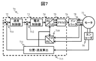
- the motor control method and the motor control device assume the speed control system 71 in the cascade FB control system of the AC servomotor shown in FIG. 7, and the model of the control object is specifically the following equation (21) It shall be shown to (22) and (23).
- Psm is a nominal plant model in the speed control system
- Mi is a model idealizing the current control system which is a minor loop control system in the speed control system
- ⁇ sm is included in the closed loop of the current control system and the speed control system It is the sum of all delays.
- J, Ka and Pp are inertia, motor constant and pole-log, respectively
- ⁇ i is a response frequency of the current control system.
- Equations (21) to (23) indicate that it is necessary to handle the problem that the controlled object has a pole at the origin in the design of the speed control system in the cascaded FB control system of the AC servomotor.
- the velocity FB controller 72 of the velocity control system is a PI controller, and is given by the following equations (24), (25) and (26).
- L and ⁇ s are the break point ratio and the response frequency of the speed control system, respectively.
- ⁇ i is set to about several to ten times ⁇ s.
- the current control system can not be approximated to 1 unless ⁇ i is simultaneously increased, and it must be regarded as a delay element.
- the current control system is a first-order delay element as shown in equation (23), and it is necessary to regard this as a delay element.
- the current control system is regarded as a delay element.
- a delay compensator 82 shown in FIG. 8 is configured, and as a design example of the filter 81, the following equation (27) is cited.
- velocity FB controller 86 While having the same structure as the velocity FB controller 86, its control design parameters are determined independently of the velocity FB controller 86.
- the denominator of equation (27) includes the response Mi of the current control system in addition to exp (- ⁇ m ⁇ s), and the order of the transfer function of the filter of equation (27) tends to be high. is there. Therefore, when the equation (27) is processed by the digital arithmetic unit 713, a high operation cost is required.
- the delay compensator 92 in the present embodiment has the rotational speed of the AC servomotor to be controlled with respect to the manipulated variable u output from the velocity FB controller 86 and the manipulated variable u output from the velocity FB controller 86. It has a sensor detection value y as an input, and outputs a speed FB signal yb with respect to the target rotational speed r.
- the delay compensator 92 rotates the model of the object to be controlled with respect to a signal obtained by the adder / subtractor 94 adding the output of an arbitrary velocity FB controller 93 to the AC servomotor to be controlled and the manipulated variable output by the velocity FB controller 86.
- the model error signal ye is calculated by subtracting the speed response from the sensor detection value y of the rotational speed of the AC servomotor which is the control object with respect to the operation amount output by the FB controller 86 by the adder / subtractor 89.
- the delay compensator 92 calculates the response of the plant nominal model 84 to the signal obtained by adding the output of an arbitrary velocity FB controller 93 and the manipulated variable output from the velocity FB controller 86 by the adder-subtractor 94 as a predicted FB signal. Then, the signal obtained by processing the model error signal by the filter 91 and the predicted FB signal are added by the adder-subtractor 95, and the result is output as the speed FB signal yb with respect to the target rotational speed r.
- the speed FB controller 86 receives a deviation signal obtained by subtracting the speed FB signal yb output from the delay compensator 92 from the target rotational speed r by the adder / subtractor 87, and generates the manipulated variable u for the control target.
- CsA and As (s) are designed, for example, as in the following formulas (29) and (30).
- the delay compensator 92 designed in this way has an input / output characteristic equivalent to that of the delay compensator 82 including the filter N shown by the equations (27) and (28) designed in Patent Document 1 from the simple calculation. It can be confirmed that That is, the delay compensator 92 designed as in equations (29) and (30) is equivalent to the delay compensator 82 including the filter of equations (27) and (28) designed in Patent Document 1 It has performance.
- Equations (29) and (30) both include the transfer characteristic Pm of the nominal plant model 84 that the equation (27) included, and the transfer characteristic Mi ⁇ exp ( ⁇ m ⁇ s) of the nominal delay element model 85. It turns out that the transfer function is simple.
- the delay compensator 92 in the speed control system of the AC servomotor shown in FIG. 9 is equivalent to the delay compensator 82 adopting various filters N designed in the prior art.
- the compensation performance can be shown, and the calculation cost can be reduced as compared with the delay compensator 82 of the prior art.
- the delay compensator 92 shown in FIG. 9 when the delay compensator 92 shown in FIG. 9 is mounted on the digital arithmetic unit 713, the calculation cost of the digital arithmetic unit 713 applied to the filter 81 of the delay compensator 82 is reduced without deterioration of control performance compared It is a control method suitable for implementation that can be reduced.
- control method it is possible to provide a control device by the digital arithmetic device 713 which is cheaper and has low operation performance.
- the filter 81 of the delay compensator 82 is expressed by the following equation (31), using the prior art:
- the delay compensator 82 shown in FIG. 9 and the delay compensator 82 including the filter of the equation (31) have equivalent compensation characteristics.
- the delay compensator 92 adopting the equation (28) can be said to be a control method suitable for mounting, if it is the equation (33), without particularly increasing the calculation cost.
- control method it is possible to provide a control device by the digital arithmetic device 713 which is cheaper and has low operation performance.
Abstract
An objective of the present invention is to provide a feedback control method involving a lag compensator appropriate for implementation and a motor control device using said feedback control method such that computation costs can be reduced for the lag compensator which is capable of reducing step disturbances added to the input end of a plant without leaving errors even if the plant has a pole at the origin. To achieve the objective, provided is a lag compensator 1 which comprises a feedback controller 1, a filter 1, and a model of a plant, receives the output of a feedback controller 2 and a response by the plant as input, and outputs a feedback signal for the controller 2, wherein the lag compensator 1 produces as a manipulation quantity 1 a signal obtained by adding the output of the controller 1 and the output of the controller 2, subtracts an output of the model of the plant in response to the manipulation quantity 1 from the response of the plant to obtain an error signal 1 to be used as the input for the controller 1, and adds a signal resulting from passing the error signal 1 through the filter to the response of the nominal plant model to the manipulation quantity to produce the output signal.
Description
本発明は、フィードバック制御方法、及びその制御方法を備えたモータ制御装置に関する。
The present invention relates to a feedback control method and a motor control device provided with the control method.
近年、FA分野では生産性向上のためにモータの益々の高速・高精度化制御が求められている。
In recent years, in the field of FA, there has been a demand for increasingly faster and more accurate control of motors to improve productivity.
モータをフィードバック制御する際、外乱を抑制し制御量を目標値に高速・高精度に追従させるには制御ゲインを高めればよい。しかしながらフィードバックループ内に遅れ要素(例えばローパスフィルタやディジタル制御装置の演算遅れ)が存在する場合、これが原因でフィードバック制御系の制御ゲインの設定上限は制約を受け、高速・高精度な目標値追従の妨げになることが一般に知られている。
When feedback control of the motor is performed, the control gain may be increased in order to suppress the disturbance and make the control amount follow the target value at high speed with high accuracy. However, when there is a delay element (for example, an operation delay of a low pass filter or digital controller) in the feedback loop, the upper limit of the control gain of the feedback control system is restricted due to this, and high speed / high accuracy target value tracking It is generally known to be a hindrance.
制御対象が原点に極を有する場合においても、フィードバック制御系の閉ループ内に存在する遅れ要素を補償でき、制御対象の入力端に加わるステップ外乱を定常偏差無く抑制できる遅れ補償器の設計方法として、特許文献1が提案されている。
As a method of designing a delay compensator which can compensate for a delay element existing in a closed loop of a feedback control system even when the control target has a pole at the origin and can suppress step disturbances applied to the input end of the control target without steady deviation. Patent Document 1 is proposed.
特許文献1では、図6に示すように、従来技術であるSmith法に、フィルタ61を追加した遅れ補償器62(N=1で従来のSmith法に一致)において、制御対象が原点に極を有する場合であっても制御対象の入力端に加わるステップ外乱を定常偏差無く抑制でき、かつフィルタ61の設計パラメータの物理的意味が理解しやすいという特徴を有するフィルタ61の設計方法が示されている。この設計方法により設計された様々な構成のフィルタ61を遅れ補償器62に採用することで、上述の特徴を有する様々な遅れ補償器62を設計できる。
In Patent Document 1, as shown in FIG. 6, in the delay compensator 62 (corresponding to the conventional Smith method with N = 1) in which the filter 61 is added to the Smith method of the prior art, the control target has a pole at the origin A method of designing the filter 61 is shown, which is characterized in that even if it has the step disturbance applied to the input end of the control object can be suppressed without steady-state deviation and the physical meaning of the design parameter of the filter 61 can be easily understood. . By adopting the filters 61 of various configurations designed by this design method as the delay compensator 62, it is possible to design various delay compensators 62 having the above-mentioned features.
特許文献1では、図6に示すフィルタ61の設計例として、以下に示す式(1)、式(2)の構成を挙げている。
In patent document 1, the structure of Formula (1) shown below and Formula (2) is mentioned as a design example of the filter 61 shown in FIG.


但し、Pmは制御対象のノミナルプラントモデル14、Cb(θ1)はθ1を調整パラメータとして有し目標値と制御対象応答との偏差を抑制可能なフィードバック制御器16、τmは制御対象12に含まれる遅れ時間τfとフィードバック遅れ要素13に含まれる遅れ時間τbの総和のモデル値、exp(-τm・s)は遅れ時間τmによるノミナルな遅れ要素モデル15である。
However, Pm is a nominal plant model 14 to be controlled, Cb (θ 1) has θ 1 as an adjustment parameter, a feedback controller 16 capable of suppressing the deviation between the target value and the control target response, and τ m is included in the control object 12 The model value of the sum of the delay time τf and the delay time τb included in the feedback delay element 13, exp (−τm · s), is a nominal delay element model 15 with the delay time τm.
また、Caは制御対象に対して有効に機能する任意のフィードバック制御器であり、Caをフィードバック制御器Cbと同構造にする場合は、Caは式(3)のように定められるものである。
Further, Ca is an optional feedback controller that effectively functions with respect to the control target, and in the case where Ca has the same structure as the feedback controller Cb, Ca is determined as shown in equation (3).
しかしながら、式(1)、式(2)で示されたフィルタ61は分母にexp(-τm・s)を含んでおり、exp(-τm・s)を厳密に演算する場合は勿論、これをPade近似法等を用いて低次の伝達関数で近似する場合においても、式(1)、式(2)で示されるフィルタの伝達関数の次数は高くなる傾向にある。
However, the filter 61 represented by the equation (1) and the equation (2) includes exp (-. Tau.m.s) in the denominator, and, of course, when exp (-. Tau.m.s) is calculated strictly Even in the case of approximation by a low order transfer function using the Pade approximation method or the like, the order of the transfer function of the filter represented by the equations (1) and (2) tends to be high.
したがって、例えば、式(1)、式(2)で示される特許文献1で設計された、図6に示す遅れ補償器62のフィルタ61をディジタル演算装置等のハードウェアへ実装する場合、ハードウェア上でのフィルタ処理にかかる演算コストが高くなるという課題があった。
Therefore, for example, when the filter 61 of the delay compensator 62 shown in FIG. 6, which is designed in Patent Document 1 shown by Equation (1) and Equation (2), is mounted on hardware such as a digital arithmetic device, hardware There is a problem that the calculation cost for the above filter processing is high.
本発明はこのような課題を鑑みてなされたものであり、特許文献1の設計方法で設計された、例えば、式(1)、式(2)で示したフィルタ61を含む遅れ補償器62をディジタル演算装置等のハードウェアへ実装する際、遅れ補償器62のフィルタ61にかかるハードウェアの演算コストを低減できる、実装に好適な制御方式、およびそれを備えた制御装置を提供することを目的とする。
The present invention has been made in view of such problems, and for example, a delay compensator 62 including the filter 61 shown by the equations (1) and (2), which is designed by the design method of Patent Document 1, It is an object of the present invention to provide a control method suitable for mounting, and a control device including the same, which can reduce the calculation cost of hardware of the filter 61 of the delay compensator 62 when mounting on hardware such as a digital arithmetic device. I assume.
本発明は、上記背景技術及び課題に鑑み、その一例を挙げるならば、制御対象のモデルと任意のフィルタ1と任意のフィードバック制御器1とから構成される遅れ補償器1を含むフィードバック制御方法であって、制御対象のモデルは、制御対象のダイナミクスを模擬するノミナルプラントモデルとフィードバック制御系の閉ループ内に内包される遅れ要素を模擬するノミナルな遅れモデルとからなり、遅れ補償器1は、制御対象に対してフィードバック制御を行うフィードバック制御器2が出力する操作量と制御対象の出力信号とを入力信号とし、操作量と、遅れ補償器1が含む任意のフィードバック制御器1の出力とを加減算器で加算した信号に対するノミナルプラントモデルの出力信号を理想フィードバック信号とし、操作量と、遅れ補償器1が含む任意のフィードバック制御器1の出力とを加減算器で加算した信号に対する制御対象のモデルの出力信号と、制御対象の出力信号とを加減算器で減じて得た信号をモデル誤差信号とし、モデル誤差信号を任意のフィードバック制御器1の入力とするとともに、モデル誤差信号を任意のフィルタ1で処理した信号と理想フィードバック信号とを加減算器で加算した信号を出力信号とするものであって、フィードバック制御器2は、遅れ補償器1の出力信号と目標値信号との偏差を加減算器で算出し、該偏差を基に制御対象に対してフィードバック補償を行う。
In view of the above background art and problems, the present invention is a feedback control method including a delay compensator 1 including a model of an object to be controlled, an optional filter 1 and an optional feedback controller 1 in an example. The model of the control target includes a nominal plant model that simulates the dynamics of the control target and a nominal delay model that simulates a delay element included in the closed loop of the feedback control system, and the delay compensator 1 controls The manipulated variable output by the feedback controller 2 that performs feedback control on the object and the output signal of the controlled object are input signals, and the manipulated variable and the output of any feedback controller 1 included in the delay compensator 1 are added / subtracted Output signal of the nominal plant model to the signal added by A signal obtained by subtracting the output signal of the model to be controlled with respect to the signal obtained by adding the output of an arbitrary feedback controller 1 included in the compensator 1 by the adder / subtracter and the output signal of the control target by the adder / subtracter A model error signal is input to an arbitrary feedback controller 1, and a signal obtained by processing the model error signal by an arbitrary filter 1 and an ideal feedback signal is added to an output signal as an output signal. The feedback controller 2 calculates the deviation between the output signal of the delay compensator 1 and the target value signal with an adder / subtractor, and performs feedback compensation on the control target based on the deviation.
本発明によれば、ハードウェア実装において演算コストを低減できる、実装に好適なフィードバック制御方法、及びそれを備えたモータ制御装置を提供できる。
According to the present invention, it is possible to provide a feedback control method suitable for implementation that can reduce the operation cost in hardware implementation, and a motor control apparatus including the same.
以下、本発明の実施例について図面を参照しながら説明する。なお、各図において、共通な機能を有する構成要素には同一の番号を付与し、その説明を省略する。また、以降、「フィードバック」は「FB」と略記する。例えば「フィードバック制御器は「FB制御器」と略記する。また「フィードフォワード」は「FF」と略記する。例えば「フィードフォワード制御器は「FF制御器」と略記する。
Hereinafter, embodiments of the present invention will be described with reference to the drawings. In the drawings, components having common functions are assigned the same reference numerals and descriptions thereof will be omitted. Also, hereinafter, "feedback" is abbreviated as "FB". For example, "feedback controller is abbreviated as" FB controller ". "Feed forward" is abbreviated as "FF". For example, “feed forward controller” is abbreviated as “FF controller”.
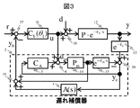
本実施例に係るモータ制御方式、およびそれを備えたモータ制御装置では、図3に示すように、遅れを含む制御対象12に対して、遅れ補償器2とFB制御器16とでFB制御系が構成されているものとする。
In the motor control method according to the present embodiment and the motor control device provided with the same, as shown in FIG. 3, an FB control system including the delay compensator 2 and the FB controller 16 with respect to the control object 12 including a delay. Shall be configured.
図3において、CAおよびA(s)は、各々制御対象に対して有効に機能する任意のFB制御器3およびフィルタ1である。本実施例において、これらは特許文献1で設計されたフィルタ61(例えば前述の式(1)、式(2))を有する図6に示した遅れ補償器62と等価な補償性能を導くために好適に構成されるものである。
In FIG. 3, CA and A (s) are optional FB controllers 3 and filters 1 that function effectively for the control target. In this embodiment, in order to derive the compensation performance equivalent to the delay compensator 62 shown in FIG. 6 having the filter 61 (for example, the above-mentioned equations (1) and (2)) designed in Patent Document 1 It is suitably configured.
遅れ補償器2は、FB制御器3、フィルタ1、および制御対象のモデルから構成される。本実施例において制御対象のモデルは、ノミナルプラントモデル14およびノミナルな遅れ要素モデル15からなるものとし、これは実際の制御対象である制御対象12とFB遅れ要素13とによる動特性を模擬したものである。すなわち、制御対象のモデルは、制御対象のダイナミクスを模擬するノミナルプラントモデルとフィードバック制御系の閉ループ内に内包される遅れ要素を模擬するノミナルな遅れモデルとからなる。
The delay compensator 2 includes an FB controller 3, a filter 1, and a model of a control target. In the present embodiment, the model to be controlled consists of a nominal plant model 14 and a nominal delay element model 15, which simulates the dynamic characteristics of the control object 12 to be actually controlled and the FB delay element 13. It is. That is, the model of the control target includes a nominal plant model that simulates the dynamics of the control target, and a nominal delay model that simulates a delay element included in the closed loop of the feedback control system.
なお、フィルタやマイナーループ制御系等、遅れを発生させる要素が閉ループ系内に含まれる場合は、制御対象のモデルは、それらの遅れ要素のノミナルなモデルを含むものとしてもよい。
When an element generating delay is included in the closed loop system, such as a filter or a minor loop control system, the model of the control target may include a nominal model of the delay elements.
以降、制御対象12とFB遅れ要素13とを直列に接続した伝達特性を単に制御対象と称する場合がある。
Hereinafter, the transfer characteristic in which the control target 12 and the FB delay element 13 are connected in series may be simply referred to as a control target.
遅れ補償器2は、FB制御器16が出力する操作量と、FB制御器16が出力する操作量に対する制御対象の出力とを入力に持ち、目標値rに対するFB信号を出力する。
The delay compensator 2 has as inputs the manipulated variable output by the FB controller 16 and the output of the controlled object with respect to the manipulated variable output by the FB controller 16, and outputs an FB signal with respect to the target value r.
遅れ補償器2の動作を図3に基づき説明する。遅れ補償器2は、任意のFB制御器3の出力とFB制御器16が出力する操作量とを加減算器4で加算した信号に対する制御対象のモデルの応答を、FB制御器16が出力する操作量に対する制御対象の応答出力から、加減算器39で減じることでモデル誤差信号を算出する。
The operation of the delay compensator 2 will be described based on FIG. The delay compensator 2 is an operation in which the FB controller 16 outputs a response of a model to be controlled to a signal obtained by adding the output of an arbitrary FB controller 3 and the manipulated variable output by the FB controller 16 by the adder / subtractor 4 A model error signal is calculated by subtracting at the adder / subtractor 39 from the response output of the control object with respect to the quantity.
また、遅れ補償器2は、任意のFB制御器3の出力とFB制御器16が出力する操作量とを加減算器4で加算した信号に対するプラントノミナルモデル14の応答を予測FB信号として算出し、モデル誤差信号をフィルタ1で処理した信号と予測FB信号とを加減算器35で加算して、目標値rに対するFB信号として出力する。
Further, the delay compensator 2 calculates a response of the plant nominal model 14 to a signal obtained by adding the output of an arbitrary FB controller 3 and the manipulated variable output by the FB controller 16 by the adder / subtractor 4 as a predicted FB signal, The signal obtained by processing the model error signal by the filter 1 and the predicted FB signal are added by the adder / subtractor 35 and output as an FB signal with respect to the target value r.
FB制御器16は、目標値rから遅れ補償器2の出力したFB信号を加減算器37で減じた偏差信号を入力に受けて、制御対象に対する操作量を生成する。
The FB controller 16 receives a deviation signal obtained by subtracting the FB signal output from the delay compensator 2 from the target value r by the adder / subtractor 37, and generates an operation amount for the control target.
図3に示す遅れ補償器2を含むFB制御系において、加減算器18は制御対象の入力端に位置し、制御対象の入力端に外乱dが加わることが想定されている。
In the FB control system including the delay compensator 2 shown in FIG. 3, it is assumed that the adder / subtractor 18 is located at the input end of the control target, and the disturbance d is added to the input end of the control target.
一般に知られたSmith法で遅れ補償器を構成する場合(図6でN=1とする遅れ補償器62の場合)、制御対象が原点に極を有する場合において、制御対象の入力端に加わるステップ外乱を定常偏差なく抑制できないという問題があった。これに対し、特許文献1で設計された、例えば、式(1)、(2)のフィルタNを採用した遅れ補償器62であれば、制御対象入力端に加わるステップ外乱を定常偏差なく抑制することができる。
When the delay compensator is configured by the generally known Smith method (in the case of the delay compensator 62 where N = 1 in FIG. 6), the step added to the input end of the control target when the control target has a pole at the origin There is a problem that the disturbance can not be suppressed without steady-state deviation. On the other hand, in the case of the delay compensator 62 designed by Patent Document 1, for example, employing the filter N of Equations (1) and (2), the step disturbance applied to the control target input end is suppressed without steady deviation. be able to.
本実施例における図3に示す遅れ補償器2は、特許文献1で設計された、例えば式(1)、(2)のフィルタNを採用した遅れ補償器62と等価な補償性能を持つように設計されるものである。
The delay compensator 2 shown in FIG. 3 in the present embodiment has a compensation performance equivalent to that of the delay compensator 62 which is, for example, the filter N of the equations (1) and (2). It is designed.
このために、遅れ補償器2のCAおよびA(s)を、例えば以下の式(4)、(5)のように設計する。
For this purpose, CA and A (s) of the delay compensator 2 are designed, for example, as in the following formulas (4) and (5).
但し、Caは特許文献1で図6に示す遅れ補償器62のフィルタ61の設計の際に用いた、制御対象に対して有効に機能する任意のフィードバック制御器を示す。
However, Ca indicates an optional feedback controller that functions effectively for the control object, used in the design of the filter 61 of the delay compensator 62 shown in FIG.
式(4)、(5)のように設計された遅れ補償器は図4の遅れ補償器42に相当し、遅れ補償器42の入出力特性は、簡単な計算から、式(1)で示したフィルタNを内包する図6の遅れ補償器62と、入出力特性が等価になる。これを以下に説明する。
The delay compensators designed as equations (4) and (5) correspond to the delay compensator 42 of FIG. 4, and the input / output characteristics of the delay compensator 42 are expressed by equation (1) from simple calculation The input / output characteristics are equivalent to the delay compensator 62 shown in FIG. 6 including the filter N. This is explained below.
図6の遅れ補償器62の入出力特性は次式で書ける。
The input / output characteristics of the delay compensator 62 shown in FIG.
他方、図3の遅れ補償器42の入出力特性は、図3から導かれる次式(7)、(8)を入出力に関して整理して、式(9)のように書ける。
On the other hand, the input / output characteristics of the delay compensator 42 of FIG. 3 can be written as Expression (9) by arranging the following equations (7) and (8) derived from FIG. 3 with respect to the input and output.

式(9)は、式(4)、(5)とすることで、式(6)と等しくなる。したがって、図3の遅れ補償器2に対して、式(4)、(5)のように設計された遅れ補償器42は、式(1)で示したフィルタNを内包する図6の遅れ補償器62と入出力特性と等価になることがわかる。
Formula (9) becomes equal to Formula (6) by setting Formula (4), (5). Therefore, with respect to the delay compensator 2 of FIG. 3, the delay compensator 42 designed as the equations (4) and (5) has the delay compensation of FIG. 6 including the filter N shown in the equation (1). It can be seen that the device 62 is equivalent to the input / output characteristic.
また、遅れ補償器2のCAおよびA(s)を、例えば以下の式(10)、(11)のように設計する。
Further, CA and A (s) of the delay compensator 2 are designed, for example, as in the following formulas (10) and (11).

式(10)、(11)のように設計された遅れ補償器2は、式(6)~式(9)と同様の式展開により、式(2)で示したフィルタNを内包する図6の遅れ補償器62と、入出力特性が等価になることが確認できる。
The delay compensator 2 designed as the equations (10) and (11) includes the filter N shown in the equation (2) by the equation expansion similar to the equations (6) to (9). It can be confirmed that the input / output characteristics are equivalent to the delay compensator 62 of FIG.
式(4)~(5)、式(10)~(11)はいずれも、式(1)、(2)が含んでいたノミナルプラントモデル14の伝達特性Pmや、ノミナルな遅れ要素モデル15の伝達特性exp(-τm・s)を含まない、簡素な伝達関数になっていることがわかる。
In all of Equations (4) to (5) and Equations (10) to (11), the transfer characteristic Pm of the nominal plant model 14 and the nominal delay element model 15 included in Equations (1) and (2) It can be seen that the transfer function is a simple transfer function that does not include the transfer characteristic exp (−τm · s).
このようにCAおよびA(s)の伝達関数が、式(1)、(2)に比較して簡素化される理由は、式(1)、(2)が含んでいたPmやexp(-τm・s)の演算を、図中のノミナルプラントモデル14とノミナルな遅れ要素モデル15の演算と共通化できるようなブロック構成として遅れ補償器2を構成したためである。
The reason why the transfer functions of CA and A (s) are simplified as compared with equations (1) and (2) is the reason why Pm and exp (-) included in equations (1) and (2) This is because the delay compensator 2 is configured as a block configuration that can share the calculation of τm · s) with the calculation of the nominal plant model 14 and the nominal delay element model 15 in the figure.
次に、図3で示した遅れ補償器2の特性について、図1、2を用いて説明する。図1および図2の指令値応答r→yおよび外乱応答d→yは、各々図4、図3に示す指令値応答r→yおよび外乱応答d→yと等価であり、すなわち、図1、図2は各々図4、図3と応答が等価な制御系である。また、図1は図2でA(s)=1とした場合である。
Next, the characteristics of the delay compensator 2 shown in FIG. 3 will be described using FIGS. The command value response r → y and the disturbance response d → y in FIGS. 1 and 2 are equivalent to the command value response r → y and the disturbance response d → y shown in FIGS. 4 and 3, respectively, that is, FIG. FIG. 2 shows a control system whose response is equivalent to that of FIGS. 4 and 3, respectively. Further, FIG. 1 shows the case where A (s) = 1 in FIG.
まず、図1に基づき遅れ補償器2の特性について説明する。図1において、rs→yの伝達特性は、規範モデル型実FB制御系7によって与えられている。以降説明の簡単化のために、外乱は無いものとしd=0とみなす。但しd≠0であった場合でも、以降の説明は成立ことに注意する。
First, the characteristics of the delay compensator 2 will be described based on FIG. In FIG. 1, the transfer characteristic of rs → y is given by the reference model type real FB control system 7. In order to simplify the explanation below, it is assumed that there is no disturbance and d = 0. However, it should be noted that even if d 説明 0, the following description is true.
ノミナルプラントモデル14とノミナルな遅れ要素モデル15、およびFB制御器CA3を用いて、図1に示すようにモデルFB制御系8を構成する。モデルFB制御系8において、yは指令に相当し、uは応答rs→ymにおけるFF操作量とみなせる。したがって、モデルFB制御系8はrs→yの伝達特性を有する規範モデル型実FB制御系7の応答yに追従するように構成された、モデル追従型2自由度制御の構成になっている。したがってFB制御器Cbは、モデル応答ymを実応答yに高応答に一致させる理想的なゲイン設定とすることでFF制御器の役割を担い、FB制御器CAは、モデル応答ymと実応答yとの偏差を補償する役割を担う。FB制御器CAは、2自由度制御の観点から、FB制御器Cbとは独立に、偏差y-ymを安定かつロバストに抑制できるよう、設計することができる。
A model FB control system 8 is configured as shown in FIG. 1 using the nominal plant model 14, the nominal delay element model 15, and the FB controller CA3. In the model FB control system 8, y corresponds to a command, and u can be regarded as an FF manipulated variable in the response rs → ym. Therefore, the model FB control system 8 is configured to follow the response y of the reference model type real FB control system 7 having a transfer characteristic of rs → y, and is configured as a model following type two degree of freedom control. Therefore, the FB controller Cb plays the role of an FF controller by setting the model response ym to an ideal response that matches the actual response y to a high response, and the FB controller CA performs the model response ym and the actual response y. Play a role in compensating for deviations from The FB controller CA can be designed so as to stably and robustly suppress the deviation y-ym independently of the FB controller Cb from the viewpoint of two-degree-of-freedom control.
結果として図1の制御器構成は、モデル応答ym-実応答y→0を高応答かつ、安定、ロバストに実現可能である。
As a result, the controller configuration of FIG. 1 can realize the model response ym-the actual response y → 0 with high response, stability and robustness.
また、図1において、CA=0とした場合、一般に知られるSmith法(図6でN=1とした場合)と等価になる。
Further, in FIG. 1, when CA = 0, this is equivalent to the commonly known Smith method (when N = 1 in FIG. 6).
図1に示すyiは、図3で説明した予測FB信号であり、CA=0としたSmith法においてもその役割は変わらない。Smith法は、遅れを含む実応答yをモデル応答ymで相殺し、遅れを含まない予測FB信号yiに基づいてFB制御器Cbを駆動することで、遅れを補償するものである。このとき、制御対象が原点に極を有する場合や制御対象が不安定な場合、実応答yをモデル応答ymで相殺することが困難となることが理由で、Smith法は一般に、制御対象が原点に極を有する場合や制御対象が不安定な場合には適用困難とされた。
Yi shown in FIG. 1 is the predicted FB signal described in FIG. 3, and its role does not change even in the Smith method with CA = 0. The Smith method compensates for the delay by canceling the actual response y including the delay with the model response ym and driving the FB controller Cb based on the predicted FB signal yi not including the delay. At this time, when the control target has a pole at the origin, or when the control target is unstable, it is difficult to offset the actual response y by the model response ym. It is considered difficult to apply when there is a pole in the case or when the controlled object is unstable.
本実施例の制御器構成においても、加減算器5および加減算器6によってym-yが成され、FB制御器Cbは指令値r-予測FB信号yiに基づいてFB制御を行う点で、遅れ補償の考え方はSmith法と同じである。但し本実施例の制御器構成は、前述のように、モデル応答ym-実応答y→0を高応答かつ、安定、ロバストに実現可能である。したがって本実施例の制御器構成はモデル追従型2自由度制御の構成とすることによって、Smith法の欠点であったモデル応答ymによる実応答yの相殺性を改善したものとみなすことができる。
Also in the controller configuration of this embodiment, the adder-subtractor 5 and the adder-subtractor 6 form ym-y, and the FB controller Cb performs the FB control based on the command value r-predicted FB signal yi. The idea of is the same as the Smith method. However, as described above, the controller configuration of this embodiment can realize the model response ym-the actual response y → 0 in a high response, stably and robustly. Therefore, the controller configuration of the present embodiment can be regarded as having improved the cancellation of the actual response y due to the model response ym, which is the drawback of the Smith method, by adopting the configuration of the model following type of two degree of freedom control.
図3と等価な制御系である図2は、任意のフィルタA(s)が規範モデル型実FB制御系27のFB信号を処理するとともに、任意のフィルタA(s)がモデル応答を処理し、処理結果を加減算器6に渡す構成となっている。すなわちモデル応答ym-実応答yを任意のフィルタA(s)で処理する構成となっており、実応答yをモデル応答ymで相殺する相殺特性を任意のフィルタA(s)で調整できる構成である。但し、A(s)≠1である場合は、図2の構成ではモデル応答ymと実応答yを別々にA(s)でフィルタ処理する必要があり、演算コストの面で有利でない。この場合は図2と等価な伝達特性である図3に示す構成を採用する。図3の構成では、フィルタA(s)はモデル応答ym-実応答yに対して一度のみ演算され、A(s)にかかる演算コストの重複を避けることができる。したがってA(s)≠1である場合は図3の構成を採用することで、演算コスト面で図2の構成より有利になる。
In FIG. 2 which is a control system equivalent to FIG. 3, an arbitrary filter A (s) processes the FB signal of the reference model type real FB control system 27, and an arbitrary filter A (s) processes a model response. The processing results are sent to the adder / subtractor 6. That is, the model response ym-the actual response y is processed by an arbitrary filter A (s), and the cancellation characteristic of canceling the actual response y by the model response ym can be adjusted by an arbitrary filter A (s) is there. However, when A (s) ≠ 1, the model response ym and the actual response y need to be separately filtered with A (s) in the configuration of FIG. 2, which is not advantageous in terms of calculation cost. In this case, the configuration shown in FIG. 3, which is a transfer characteristic equivalent to that of FIG. 2, is employed. In the configuration of FIG. 3, the filter A (s) is calculated only once for the model response ym−the actual response y, and duplication of the calculation cost for A (s) can be avoided. Therefore, when A (s) ≠ 1, adopting the configuration of FIG. 3 is advantageous over the configuration of FIG. 2 in terms of calculation cost.
上記のことから、特許文献1で設計されたフィルタNに関して、例えば式(1)、式(2)で示されたNを採用した場合、図1もしくは図3の構成で実装することで、特許文献1に記載の図6に示す構成で実装するよりも演算コストを低減することができる。また図1もしくは図3はモデル追従型2自由度制御の構成を成しモデル応答ym-実応答y→0を高応答かつ、安定、ロバストに実現できることから、図1もしくは図3の構成によれば、Smith法の欠点であったモデル応答ymによる実応答yの相殺性を改善でき、制御対象が原点に極を有する場合であっても、高応答かつ安定的に遅れを補償することが可能である。
From the above, with respect to the filter N designed in Patent Document 1, for example, when N shown in Formula (1) and Formula (2) is adopted, it is mounted by the configuration of FIG. 1 or FIG. The operation cost can be reduced more than that of the configuration shown in FIG. Also, FIG. 1 or FIG. 3 is configured as shown in FIG. 1 or FIG. 3 because it constitutes a configuration of model following type of two degree of freedom control and can realize model response ym-actual response y → 0 with high response and stability and robustness. For example, it is possible to improve the cancellation of the actual response y due to the model response ym, which is a drawback of the Smith method, and to compensate the delay with high response and stability even when the controlled object has a pole at the origin. It is.
次に、図3記載の本実施例の遅れ補償器2が、従来の遅れ補償器62と比較して演算コストをどの程度低減できるかを、簡単な例を用いて説明する。
Next, how much the calculation cost can be reduced by the delay compensator 2 of the present embodiment shown in FIG. 3 compared to the conventional delay compensator 62 will be described using a simple example.
図6で示すFB制御系において、フィルタ61は式(1)で示すものを採用したとする。これに等価なFB制御系は、前述のように図4で示す遅れ補償器42を含むFB制御系である。FB制御器CbはPI制御器とし、以下の式(12)に示すようにFB制御器Cbは応答周波数ωbで制御応答性を調整できるものとする。
In the FB control system shown in FIG. 6, it is assumed that the filter 61 adopts the one represented by the equation (1). An equivalent FB control system is an FB control system including the delay compensator 42 shown in FIG. 4 as described above. The FB controller Cb is a PI controller, and the FB controller Cb can adjust the control response at the response frequency ωb as shown in the following equation (12).

但し、Nは任意の正の実数である。
However, N is any positive real number.
また、簡単のためにノミナルな遅れ要素モデル15の伝達特性をPade近似(1次)で以下の式(13)のように近似した場合を考える。
Further, for the sake of simplicity, it is assumed that the transfer characteristic of the nominal delay element model 15 is approximated by Pade approximation (first order) as shown in the following equation (13).

さらに、式(1)に含まれる任意のFB制御CaはFB制御器Cbと同構造を有すると仮定する。すなわち、式(3)の仮定を設け、FB制御器Caは応答周波数ωaでωbとは独立に制御性を調整できるものとする。
Furthermore, it is assumed that any FB control Ca included in the equation (1) has the same structure as the FB controller Cb. That is, it is assumed that the FB controller Ca can adjust the controllability independently of ωb at the response frequency ωa, under the assumption of the equation (3).
上記の仮定の下、式(1)のフィルタは次式(14)、(15)、(16)となる。
Under the above assumption, the filter of equation (1) becomes the following equations (14), (15) and (16).


図6において、FB制御器16の操作量uと制御対象の出力からモデル誤差信号yeが得られている場合、遅れ補償器62の出力ybは次式(17)で算出される。
In FIG. 6, when the model error signal ye is obtained from the operation amount u of the FB controller 16 and the output of the control object, the output yb of the delay compensator 62 is calculated by the following equation (17).

他方、図4において、FB制御器3の出力が以前の状態量として既に算出されている前提に立って、FB制御器16の操作量uと制御対象の出力からモデル誤差信号yeが得られている場合、遅れ補償器2の出力ybは次式(18)で算出される。
On the other hand, on the premise that the output of the FB controller 3 is already calculated as the previous state quantity in FIG. 4, a model error signal ye is obtained from the manipulated variable u of the FB controller 16 and the output of the control target In this case, the output yb of the delay compensator 2 is calculated by the following equation (18).

式(17)、(18)を比較すると、右辺第2項が異なっており、式(18)の右辺第2項のほうが伝達関数の次数が低い。したがって、本実施例の遅れ補償器42のほうが、従来の遅れ補償器62に比べて、出力信号ybの算出にかかる演算コストが低いことがわかる。
Comparing the equations (17) and (18), the second term on the right side is different, and the second term on the right side of the equation (18) has a lower order of the transfer function. Therefore, it can be understood that the calculation cost for calculating the output signal yb is lower in the delay compensator 42 of this embodiment than in the conventional delay compensator 62.
この例ではPade近似を1次としたが、より高次のPade近似とする場合は、式(17)右辺第2項の伝達関数の次数が増大するため、本実施例の遅れ補償器42による演算コストの低減がより効果的となることがわかる。
In this example, the Pade approximation is a first-order, but in the case of a higher-order Pade approximation, the order of the transfer function of the second term on the right side of the equation (17) is increased. It can be seen that the reduction of computational cost is more effective.
特許文献1で設計された式(1)、式(2)以外のフィルタNであっても、フィルタNが次式(19)のように表現できるものとして設計された場合は、図3に示す遅れ補償器2の構成で、図6に示す遅れ補償器62と等価な補償特性を実現でき、かつ図6に示す遅れ補償器62よりも演算コストを低減できる。
Even if the filter N is a filter N other than the formulas (1) and (2) designed in Patent Document 1, it is shown in FIG. 3 when the filter N is designed as one that can be expressed as the following formula (19). The configuration of the delay compensator 2 can realize a compensation characteristic equivalent to that of the delay compensator 62 shown in FIG. 6, and can reduce the operation cost more than the delay compensator 62 shown in FIG.

例えば、図3の遅れ補償器2のフィルタA(s)を式(20)のように、
For example, the filter A (s) of the delay compensator 2 of FIG.
と定数γで定義した場合は、図5に示す遅れ補償器52となる。証明は省略するが、この構成であっても、制御対象が原点に極を有する場合において制御対象の入力端に加わるステップ外乱を定常偏差なく抑制することが可能である。
And the constant γ, the delay compensator 52 shown in FIG. 5 is obtained. Although proof is omitted, even in this configuration, it is possible to suppress the step disturbance applied to the input end of the control target without steady-state deviation when the control target has a pole at the origin.
上記説明したように、本実施例によれば、図3に示す遅れ補償器2は、従来技術で設計した様々なフィルタNを採用した遅れ補償器62と等価な補償性能を示すことができる包括性を有し、かつ従来技術の遅れ補償器62に比べて演算コストを低減できる構成であることがわかる。
As described above, according to this embodiment, the delay compensator 2 shown in FIG. 3 can exhibit compensation performance equivalent to that of the delay compensator 62 employing various filters N designed in the prior art. It can be seen that the configuration has a configuration that can reduce the operation cost compared to the delay compensator 62 of the prior art.
すなわち、図3に示す遅れ補償器2は、ディジタル演算装置等のハードウェアへ実装する際、従来技術と比較して制御性能の劣化なく、遅れ補償器62のフィルタ61にかかるハードウェアの演算コストを低減できる、実装に好適な制御方式である。
That is, when the delay compensator 2 shown in FIG. 3 is mounted on hardware such as a digital arithmetic device, the operation cost of the hardware applied to the filter 61 of the delay compensator 62 does not deteriorate compared to the prior art without deterioration in control performance. Is a control method suitable for implementation that can reduce
また、この制御方式によれば、より安価で低演算性能なハードウェアによる制御装置の提供が可能になる。
In addition, according to this control method, it is possible to provide a control device by hardware that is less expensive and has low arithmetic performance.
なお、実装対象であるディジタル演算装置等のハードウェアに演算リソースが十分ある場合は、本実施例で示した遅れ補償器2と等価な補償性能を示す遅れ補償器として、特許文献1に記載の技術で設計したフィルタ61を用いて、FB制御系を図6のように実装してもよい。
When hardware such as a digital arithmetic device to be mounted has sufficient operation resources, a delay compensator described in Patent Document 1 is described as a delay compensator having equivalent compensation performance to the delay compensator 2 shown in the present embodiment. The FB control system may be implemented as shown in FIG. 6 using a filter 61 designed by technology.
以上のように、本実施例によれば、特許文献1で設計された遅れ補償器62のフィルタ61の処理が、フィルタ61の分母に含まれるexp(-τm・s)と、フィルタ61の分子・分母に含まれるノミナルプラントモデルPmの演算とを、Smith法で必要とされるノミナルな遅れ要素モデル15とノミナルプラントモデル14との演算処理で共通化した簡易な制御ブロック構成で実現できるため、特許文献1で設計された遅れ補償器62の特徴・優位性を保持しつつ、ハードウェア実装において演算コストを低減できる、実装に好適なフィードバック制御方法、及びそれを備えたモータ制御装置を提供できる。
As described above, according to the present embodiment, the processing of the filter 61 of the delay compensator 62 designed in Patent Document 1 is included in the denominator of the filter 61, exp (-τ m · s), and the numerator of the filter 61. Since the calculation of the nominal plant model Pm included in the denominator can be realized by a simple control block configuration common to the calculation processing of the nominal delay element model 15 and the nominal plant model 14 required in the Smith method, According to the present invention, it is possible to provide a feedback control method suitable for implementation that can reduce the operation cost in hardware implementation while maintaining the features and advantages of the delay compensator 62 designed in Patent Document 1, and a motor control apparatus including the same. .
本実施例に係るモータ制御方式、およびモータ制御装置は、図7に示すACサーボモータのカスケードFB制御系における速度制御系71を想定し、制御対象のモデルは具体的に次式(21)、(22)、(23)に示すものとする。
The motor control method and the motor control device according to the present embodiment assume the speed control system 71 in the cascade FB control system of the AC servomotor shown in FIG. 7, and the model of the control object is specifically the following equation (21) It shall be shown to (22) and (23).

Psmは速度制御系におけるノミナルプラントモデル、Miは速度制御系におけるマイナーループ制御系である電流制御系を理想化したモデルであり、τsmは、電流制御系、及び速度制御系の閉ループに内包される全ての遅れの総和である。また、J、Ka、Ppは各々、イナーシャ、モータ定数、極対数であり、ωiは電流制御系の応答周波数である。
Psm is a nominal plant model in the speed control system, Mi is a model idealizing the current control system which is a minor loop control system in the speed control system, and τsm is included in the closed loop of the current control system and the speed control system It is the sum of all delays. Further, J, Ka and Pp are inertia, motor constant and pole-log, respectively, and ωi is a response frequency of the current control system.
式(21)~(23)は、ACサーボモータのカスケードFB制御系における速度制御系の設計においては、制御対象が原点に極を有する問題を取り扱うことが必要なことを示している。
Equations (21) to (23) indicate that it is necessary to handle the problem that the controlled object has a pole at the origin in the design of the speed control system in the cascaded FB control system of the AC servomotor.
速度制御系の速度FB制御器72はPI制御器とし、次式(24)、(25)、(26)とする。
The velocity FB controller 72 of the velocity control system is a PI controller, and is given by the following equations (24), (25) and (26).


但し、L、ωsは各々折れ点比、速度制御系の応答周波数である。一般に、電流制御系を近似的に1と見なすために、ωiはωsの数~10倍程度に設定される。
Where L and ωs are the break point ratio and the response frequency of the speed control system, respectively. Generally, in order to regard the current control system as approximately 1, ωi is set to about several to ten times ωs.
速度制御系の高応答化のためにωsを高めると、ωiを同時に高めない限り、電流制御系が1に近似できなくなり、遅れ要素と見なす必要がある。この場合電流制御系は式(23)に示すように1次遅れ要素であり、これを遅れ要素と見なす必要がある。
If ωs is increased to increase the response of the speed control system, the current control system can not be approximated to 1 unless ωi is simultaneously increased, and it must be regarded as a delay element. In this case, the current control system is a first-order delay element as shown in equation (23), and it is necessary to regard this as a delay element.
本実施例では、電流制御系を遅れ要素と見なす。この問題設定において、特許文献1では図8に示す遅れ補償器82が構成され、フィルタ81の設計例として次式(27)が挙げられている。
In this embodiment, the current control system is regarded as a delay element. In this problem setting, in patent document 1, a delay compensator 82 shown in FIG. 8 is configured, and as a design example of the filter 81, the following equation (27) is cited.

但し、Csaは、式(28)に示すように、
However, as shown in equation (28), Csa is
速度FB制御器86と同構造を持ちながら、その制御設計パラメータは速度FB制御器86とは独立に定められるものである。
While having the same structure as the velocity FB controller 86, its control design parameters are determined independently of the velocity FB controller 86.
従来技術によれば式(27)の分母には、exp(-τm・s)に加えて電流制御系の応答Miも含まれ、式(27)のフィルタの伝達関数の次数は高くなる傾向にある。このため式(27)をディジタル演算装置713で処理する場合は、高い演算コストが必要とされる。
According to the prior art, the denominator of equation (27) includes the response Mi of the current control system in addition to exp (-τm · s), and the order of the transfer function of the filter of equation (27) tends to be high. is there. Therefore, when the equation (27) is processed by the digital arithmetic unit 713, a high operation cost is required.
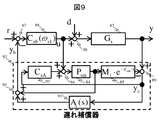
本実施例におけるACサーボモータのカスケードFB制御系における速度制御系の構成を図9に示す。図9において、本実施例における遅れ補償器92は、速度FB制御器86が出力する操作量uと、速度FB制御器86が出力する操作量uに対する制御対象であるACサーボモータの回転速度のセンサ検出値yとを入力に持ち、目標回転速度rに対する速度FB信号ybを出力する。
The configuration of the speed control system in the cascaded FB control system of the AC servomotor in this embodiment is shown in FIG. In FIG. 9, the delay compensator 92 in the present embodiment has the rotational speed of the AC servomotor to be controlled with respect to the manipulated variable u output from the velocity FB controller 86 and the manipulated variable u output from the velocity FB controller 86. It has a sensor detection value y as an input, and outputs a speed FB signal yb with respect to the target rotational speed r.
遅れ補償器92の動作を図9に基づき説明する。遅れ補償器92は、制御対象であるACサーボモータに対する任意の速度FB制御器93の出力と速度FB制御器86が出力する操作量とを加減算器94で加算した信号に対する制御対象のモデルの回転速度応答を、FB制御器86が出力する操作量に対する制御対象であるACサーボモータの回転速度のセンサ検出値yから、加減算器89で減じることでモデル誤差信号yeを算出する。
The operation of the delay compensator 92 will be described with reference to FIG. The delay compensator 92 rotates the model of the object to be controlled with respect to a signal obtained by the adder / subtractor 94 adding the output of an arbitrary velocity FB controller 93 to the AC servomotor to be controlled and the manipulated variable output by the velocity FB controller 86. The model error signal ye is calculated by subtracting the speed response from the sensor detection value y of the rotational speed of the AC servomotor which is the control object with respect to the operation amount output by the FB controller 86 by the adder / subtractor 89.
また、遅れ補償器92は、任意の速度FB制御器93の出力と速度FB制御器86が出力する操作量とを加減算器94で加算した信号に対するプラントノミナルモデル84の応答を予測FB信号として算出し、モデル誤差信号をフィルタ91で処理した信号と予測FB信号とを加減算器95で加算して、目標回転速度rに対する速度FB信号ybとして出力する。
In addition, the delay compensator 92 calculates the response of the plant nominal model 84 to the signal obtained by adding the output of an arbitrary velocity FB controller 93 and the manipulated variable output from the velocity FB controller 86 by the adder-subtractor 94 as a predicted FB signal. Then, the signal obtained by processing the model error signal by the filter 91 and the predicted FB signal are added by the adder-subtractor 95, and the result is output as the speed FB signal yb with respect to the target rotational speed r.
速度FB制御器86は、目標回転速度rから遅れ補償器92の出力した速度FB信号ybを加減算器87で減じた偏差信号を入力に受けて、制御対象に対する操作量uを生成する。
The speed FB controller 86 receives a deviation signal obtained by subtracting the speed FB signal yb output from the delay compensator 92 from the target rotational speed r by the adder / subtractor 87, and generates the manipulated variable u for the control target.
本実施例における図9に示す遅れ補償器92において、CsAおよびAs(s)は例えば以下の式(29)、(30)のように設計する。
In the delay compensator 92 shown in FIG. 9 in the present embodiment, CsA and As (s) are designed, for example, as in the following formulas (29) and (30).
但し、式(29)中のCsaは、式(28)で示したものである。
However, Csa in Formula (29) is shown by Formula (28).
このように設計された遅れ補償器92は、簡単な演算から、特許文献1で設計された式(27)、(28)で示されるフィルタNを内包する遅れ補償器82と等価な入出力特性を示すことが確認できる。すなわち、式(29)、(30)のように設計された遅れ補償器92は、特許文献1で設計された式(27)、(28)のフィルタを内包する遅れ補償器82と等価な補償性能を有する。
The delay compensator 92 designed in this way has an input / output characteristic equivalent to that of the delay compensator 82 including the filter N shown by the equations (27) and (28) designed in Patent Document 1 from the simple calculation. It can be confirmed that That is, the delay compensator 92 designed as in equations (29) and (30) is equivalent to the delay compensator 82 including the filter of equations (27) and (28) designed in Patent Document 1 It has performance.
式(29)、(30)はいずれも、式(27)が含んでいたノミナルプラントモデル84の伝達特性Pmや、ノミナルな遅れ要素モデル85の伝達特性Mi・exp(-τm・s)を含まない、簡素な伝達関数になっていることがわかる。
Equations (29) and (30) both include the transfer characteristic Pm of the nominal plant model 84 that the equation (27) included, and the transfer characteristic Mi · exp (−τm · s) of the nominal delay element model 85. It turns out that the transfer function is simple.
このように、CsAおよびAs(s)の伝達関数が、式(27)に比較して簡素化される理由は、式(27)が含んでいたPmやMi・exp(-τm・s)の演算を、ノミナルプラントモデル84とノミナルな遅れ要素モデル85の演算と共通化できるようなブロック構成として遅れ補償器92が構成されているためである。
Thus, the reason why the transfer functions of CsA and As (s) are simplified as compared to equation (27) is that Pm and Mi · exp (−τm · s) included in equation (27) This is because the delay compensator 92 is configured as a block configuration that can share the calculation with the calculation of the nominal plant model 84 and the nominal delay element model 85.
上記説明したように、本実施例によれば、図9に示すACサーボモータの速度制御系における遅れ補償器92は、従来技術で設計した様々なフィルタNを採用した遅れ補償器82と等価な補償性能を示すことができ、かつ従来技術の遅れ補償器82に比べて演算コストを低減できる構成となっている。
As described above, according to this embodiment, the delay compensator 92 in the speed control system of the AC servomotor shown in FIG. 9 is equivalent to the delay compensator 82 adopting various filters N designed in the prior art. The compensation performance can be shown, and the calculation cost can be reduced as compared with the delay compensator 82 of the prior art.
すなわち、図9に示す遅れ補償器92は、ディジタル演算装置713へ実装する際、従来技術と比較して制御性能の劣化なく、遅れ補償器82のフィルタ81にかかるディジタル演算装置713の演算コストを低減できる、実装に好適な制御方式である。
That is, when the delay compensator 92 shown in FIG. 9 is mounted on the digital arithmetic unit 713, the calculation cost of the digital arithmetic unit 713 applied to the filter 81 of the delay compensator 82 is reduced without deterioration of control performance compared It is a control method suitable for implementation that can be reduced.
また、この制御方式によれば、より安価で低演算性能なディジタル演算装置713による制御装置の提供が可能になる。
Further, according to this control method, it is possible to provide a control device by the digital arithmetic device 713 which is cheaper and has low operation performance.
なお、ACサーボモータの速度制御系において、従来技術を用いて遅れ補償器82のフィルタ81が、下式(31)、
In the speed control system of the AC servomotor, the filter 81 of the delay compensator 82 is expressed by the following equation (31), using the prior art:
のように設計された場合でも、本実施例において、図9に示す遅れ補償器92において、下式(32)、
In the present embodiment, even in the case where the delay compensator 92 is designed as follows, in the delay compensator 92 shown in FIG.
のように設計すれば、図9に示す遅れ補償器72と式(31)のフィルタを内包する遅れ補償器82は等価な補償特性となる。
The delay compensator 82 shown in FIG. 9 and the delay compensator 82 including the filter of the equation (31) have equivalent compensation characteristics.
これにおいて、例えば、下式(33)のように、
In this case, for example, as in the following equation (33),
定数γで定義した場合であっても、制御対象が原点に極を有する場合において、制御対象の入力端に加わるステップ外乱を定常偏差なく抑制することが可能である。式(33)であれば、式(30)との比較から、特段の演算コストの増加無く、式(28)を採用した遅れ補償器92は実装に好適な制御方式であるといえる。
Even when the constant γ is defined, it is possible to suppress the step disturbance applied to the input end of the controlled object without steady-state deviation when the controlled object has a pole at the origin. From the comparison with the equation (30), the delay compensator 92 adopting the equation (28) can be said to be a control method suitable for mounting, if it is the equation (33), without particularly increasing the calculation cost.
また、この制御方式によれば、より安価で低演算性能なディジタル演算装置713による制御装置の提供が可能になる。
Further, according to this control method, it is possible to provide a control device by the digital arithmetic device 713 which is cheaper and has low operation performance.
1,61,81、91:フィルタ、2、42、52、62、82、92:遅れ補償器、3,16,93:フィードバック制御器、4,5、6、18、35,37,39:加減算器、7、27:規範モデル型実フィードバック制御系、8:モデルフィードバック制御系、12:制御対象、13:フィードバック遅れ要素、14:ノミナルプラントモデル、15:ノミナルな遅れ要素モデル、71:ACサーボモータの速度制御系、77:ACサーボモータ、78:電流検出器、713:ディジタル演算装置
1, 61, 81, 91: filter, 2, 42, 52, 62, 82, 92: delay compensator, 3, 16, 93: feedback controller, 4, 5, 6, 18, 35, 37, 39: Adder / subtractor 7, 27: reference model type real feedback control system, 8: model feedback control system, 12: control target, 13: feedback delay element, 14: nominal plant model, 15: nominal delay element model, 71: AC Servo motor speed control system 77: AC servo motor 78: current detector 713: digital arithmetic unit
Claims (10)
- 制御対象のモデルと任意のフィルタ1と任意のフィードバック制御器1とから構成される遅れ補償器1を含むフィードバック制御方法であって、
前記制御対象のモデルは、制御対象のダイナミクスを模擬するノミナルプラントモデルとフィードバック制御系の閉ループ内に内包される遅れ要素を模擬するノミナルな遅れモデルとからなり、
前記遅れ補償器1は、前記制御対象に対してフィードバック制御を行うフィードバック制御器2が出力する操作量と制御対象の出力信号とを入力信号とし、
前記操作量と、前記遅れ補償器1が含む前記任意のフィードバック制御器1の出力とを加減算器で加算した信号に対する前記ノミナルプラントモデルの出力信号を理想フィードバック信号とし、前記操作量と、前記遅れ補償器1が含む前記任意のフィードバック制御器1の出力とを加減算器で加算した信号に対する前記制御対象のモデルの出力信号と、前記制御対象の出力信号とを加減算器で減じて得た信号をモデル誤差信号とし、該モデル誤差信号を前記任意のフィードバック制御器1の入力とするとともに、前記モデル誤差信号を前記任意のフィルタ1で処理した信号と前記理想フィードバック信号とを加減算器で加算した信号を出力信号とするものであって、
前記フィードバック制御器2は、前記遅れ補償器1の前記出力信号と目標値信号との偏差を加減算器で算出し、該偏差を基に前記制御対象に対してフィードバック補償を行うことを特徴とするフィードバック制御方法。 A feedback control method including a delay compensator 1 configured of a model to be controlled, an optional filter 1 and an optional feedback controller 1,
The model of the control target includes a nominal plant model that simulates the dynamics of the control target and a nominal delay model that simulates a delay element included in the closed loop of the feedback control system.
The delay compensator 1 uses an operation amount output by a feedback controller 2 that performs feedback control on the control target and an output signal of the control target as input signals.
An output signal of the nominal plant model with respect to a signal obtained by adding the manipulated variable and the output of the arbitrary feedback controller 1 included in the delay compensator 1 by an adder / subtracter is an ideal feedback signal, the manipulated variable and the delayed signal. The signal obtained by subtracting the output signal of the model to be controlled with respect to the signal obtained by adding the output of the optional feedback controller 1 included in the compensator 1 by the adder / subtractor and the output signal of the control target by the adder / subtracter A signal obtained by adding the model error signal processed by the arbitrary filter 1 and the ideal feedback signal by an adder / subtractor while using the model error signal as an input to the arbitrary feedback controller 1 As the output signal,
The feedback controller 2 calculates a deviation between the output signal of the delay compensator 1 and a target value signal with an adder / subtractor, and performs feedback compensation on the control target based on the deviation. Feedback control method. - 請求項1に記載のフィードバック制御方法であって、
前記任意のフィルタ1は、その伝達特性が0より大きい任意の実数であることを特徴とするフィードバック制御方法。 The feedback control method according to claim 1, wherein
A feedback control method characterized in that the arbitrary filter 1 is an arbitrary real number whose transfer characteristic is greater than zero. - 請求項1に記載のフィードバック制御方法であって、
前記任意のフィルタ1は、その伝達特性が1であることを特徴とするフィードバック制御方法。 The feedback control method according to claim 1, wherein
A feedback control method characterized in that the transfer characteristic of the arbitrary filter 1 is 1; - 制御対象のモデル及びフィルタ2から構成される遅れ補償器2を含むフィードバック制御方法であって、
前記制御対象のモデルは制御対象のダイナミクスを模擬するノミナルプラントモデルとフィードバック制御系の閉ループ内に内包される遅れ要素を模擬するノミナルな遅れモデルとからなり、
前記遅れ補償器2は、前記制御対象に対してフィードバック制御を行うフィードバック制御器2が出力する操作量と制御対象の出力信号とを入力信号とし、
前記制御対象の出力信号と前記フィードバック制御器2が出力する操作量に対する前記制御対象のモデルの出力信号とを加減算器で減じて得た誤差信号に対して前記フィルタ2を作用させた結果の信号と、前記フィードバック制御器2が出力する操作量に対する前記ノミナルプラントモデルの出力信号とを加減算器で加え合わせて得た信号を出力信号とするものであって、
前記フィードバック制御器2は、前記遅れ補償器2の前記出力信号と目標値信号との偏差を加減算器で算出し、該偏差を基に前記制御対象に対して補償を行うものであって、
前記フィルタ2は、前記制御対象に対する任意のフィードバック制御器3と、前記制御対象のモデルと、前記制御対象に対する任意のフィードバック制御器3と前記制御対象のモデルで構成される閉ループ系の伝達関数と、前記閉ループ系の一巡伝達関数とを、任意に用いて和差積商の形で構成した関数とすることを特徴とするフィードバック制御方法。 A feedback control method including a delay compensator 2 configured of a model to be controlled and a filter 2,
The model of the control target comprises a nominal plant model that simulates the dynamics of the control target and a nominal delay model that simulates a delay element included in the closed loop of the feedback control system.
The delay compensator 2 uses, as input signals, an operation amount output from a feedback controller 2 that performs feedback control on the control target and an output signal of the control target.
A signal obtained by causing the filter 2 to act on an error signal obtained by subtracting an output signal of the control target and an output signal of the model of the control target with respect to the manipulated variable output by the feedback controller 2 by an adder / subtractor And an output signal of the nominal plant model with respect to the manipulated variable output by the feedback controller 2 by using an adder-subtractor as an output signal.
The feedback controller 2 calculates a deviation between the output signal of the delay compensator 2 and a target value signal with an adder / subtractor, and performs compensation on the control target based on the deviation.
The filter 2 is a transfer function of a closed loop system including an arbitrary feedback controller 3 for the control object, a model of the control object, an arbitrary feedback controller 3 for the control object, and a model of the control object. A feedback control method, characterized in that the loop transfer function of the closed loop system is arbitrarily used to be a function configured in the form of a sum difference product quotient. - 請求項1に記載のフィードバック制御方法であって、
前記任意のフィードバック制御器1は、請求項4に記載の任意のフィードバック制御器3と等価な伝達特性を有するものであって、
前記任意のフィルタ1は、前記遅れ補償器1の入出力伝達特性が請求項4に記載の遅れ補償器2の入出力特性と等価になるよう、適切な次数を有する伝達関数として与えられていることを特徴とするフィードバック制御方法。 The feedback control method according to claim 1, wherein
The optional feedback controller 1 has a transfer characteristic equivalent to the optional feedback controller 3 according to claim 4;
The arbitrary filter 1 is given as a transfer function having an appropriate order so that the input / output transfer characteristic of the delay compensator 1 is equivalent to the input / output characteristic of the delay compensator 2 according to claim 4 Feedback control method characterized in that - 制御対象のモデルと任意のフィルタ1と任意のフィードバック制御器1とから構成される遅れ補償器1を含むフィードバック制御系を採用したモータ制御装置であって、
前記制御対象のモデルは、制御対象のダイナミクスを模擬するノミナルプラントモデルと前記フィードバック制御系の閉ループ内に内包される遅れ要素を模擬するノミナルな遅れモデルとからなり、
前記遅れ補償器1は、前記フィードバック制御系を構成し制御対象に対してフィードバック制御を行うフィードバック制御器2が出力する操作量と制御対象の出力信号とを入力信号とし、
前記操作量と、前記遅れ補償器1が含む前記任意のフィードバック制御器1の出力とを加減算器で加算した信号に対する前記ノミナルプラントモデルの出力信号を理想フィードバック信号とし、前記操作量と、前記遅れ補償器1が含む前記任意のフィードバック制御器1の出力とを加減算器で加算した信号に対する前記制御対象のモデルの出力信号と、前記制御対象の出力信号とを加減算器で減じて得た信号をモデル誤差信号とし、該モデル誤差信号を前記任意のフィードバック制御器1の入力とするとともに、前記モデル誤差信号を前記任意のフィルタ1で処理した信号と前記理想フィードバック信号とを加減算器で加算した信号を出力信号とするものであって、
前記フィードバック制御器2は、前記遅れ補償器1の前記出力信号と目標値信号との偏差を加減算器で算出し、該偏差を基に前記制御対象に対してフィードバック補償を行うことを特徴とするモータ制御装置。 A motor control apparatus employing a feedback control system including a delay compensator 1 including a model to be controlled, an arbitrary filter 1, and an arbitrary feedback controller 1,
The model of the control target includes a nominal plant model that simulates the dynamics of the control target and a nominal delay model that simulates a delay element included in a closed loop of the feedback control system.
The delay compensator 1 uses as an input signal an operation amount output by a feedback controller 2 that constitutes the feedback control system and performs feedback control on a control target, and an output signal of the control target.
An output signal of the nominal plant model with respect to a signal obtained by adding the manipulated variable and the output of the arbitrary feedback controller 1 included in the delay compensator 1 by an adder / subtracter is an ideal feedback signal, the manipulated variable and the delayed signal. The signal obtained by subtracting the output signal of the model to be controlled with respect to the signal obtained by adding the output of the optional feedback controller 1 included in the compensator 1 by the adder / subtractor and the output signal of the control target by the adder / subtracter A signal obtained by adding the model error signal processed by the arbitrary filter 1 and the ideal feedback signal by an adder / subtractor while using the model error signal as an input to the arbitrary feedback controller 1 As the output signal,
The feedback controller 2 calculates a deviation between the output signal of the delay compensator 1 and a target value signal with an adder / subtractor, and performs feedback compensation on the control target based on the deviation. Motor controller. - 請求項6に記載のモータ制御装置であって、
前記任意のフィルタ1は、その伝達特性が0より大きい任意の実数であることを特徴とするモータ制御装置。 The motor control device according to claim 6, wherein
A motor control device characterized in that the arbitrary filter 1 has an arbitrary real number whose transfer characteristic is greater than zero. - 請求項6に記載のモータ制御装置であって、
前記任意のフィルタ1は、その伝達特性が1であることを特徴とするモータ制御装置。 The motor control device according to claim 6, wherein
A motor control apparatus characterized in that the transmission characteristic of the arbitrary filter 1 is 1. - 制御対象のモデル及びフィルタ2から構成される遅れ補償器2とフィードバック制御器2から成るフィードバック制御系を採用したモータ制御装置であって、
前記制御対象のモデルは制御対象のダイナミクスを模擬するノミナルプラントモデルと前記フィードバック制御系の閉ループ内に内包される遅れ要素を模擬するノミナルな遅れモデルとからなり、
前記遅れ補償器2は、前記フィードバック制御器2が出力する操作量と制御対象の出力信号とを入力信号とし、
前記制御対象の出力信号と前記フィードバック制御器2が出力する操作量に対する前記制御対象のモデルの出力信号とを加減算器で減じて得た誤差信号に対して前記フィルタ2を作用させた結果の信号と、前記フィードバック制御器2が出力する操作量に対する前記ノミナルプラントモデルの出力信号とを加減算器で加え合わせて得た信号を出力信号とするものであって、
前記フィードバック制御器2は、前記遅れ補償器2の前記出力信号と目標値信号との偏差を加減算器で算出し、該偏差を基に前記制御対象に対して補償を行うものであって、
前記フィルタ2は、前記制御対象に対する任意のフィードバック制御器3と、前記制御対象のモデルと、前記制御対象に対する任意のフィードバック制御器3と前記制御対象のモデルで構成される閉ループ系の伝達関数と、前記閉ループ系の一巡伝達関数とを、任意に用いて和差積商の形で構成した関数とすることを特徴とするモータ制御装置。 A motor control apparatus employing a feedback control system including a delay compensator 2 configured of a model to be controlled and a filter 2 and a feedback controller 2,
The model of the control target includes a nominal plant model that simulates the dynamics of the control target and a nominal delay model that simulates a delay element included in the closed loop of the feedback control system.
The delay compensator 2 takes an operation amount output from the feedback controller 2 and an output signal to be controlled as an input signal.
A signal obtained by causing the filter 2 to act on an error signal obtained by subtracting an output signal of the control target and an output signal of the model of the control target with respect to the manipulated variable output by the feedback controller 2 by an adder / subtractor And an output signal of the nominal plant model with respect to the manipulated variable output by the feedback controller 2 by using an adder-subtractor as an output signal.
The feedback controller 2 calculates a deviation between the output signal of the delay compensator 2 and a target value signal with an adder / subtractor, and performs compensation on the control target based on the deviation.
The filter 2 is a transfer function of a closed loop system including an arbitrary feedback controller 3 for the control object, a model of the control object, an arbitrary feedback controller 3 for the control object, and a model of the control object. A motor control apparatus characterized in that the open loop transfer function of the closed loop system is a function formed arbitrarily in the form of a sum difference product quotient. - 請求項6に記載のモータ制御装置であって、
前記任意のフィードバック制御器1は、請求項9に記載の任意のフィードバック制御器3と等価な伝達特性を有するものであって、
前記任意のフィルタ1は、前記遅れ補償器1の入出力伝達特性が請求項9に記載の遅れ補償器2の入出力特性と等価になるよう、適切な次数を有する伝達関数として与えられていることを特徴とするモータ制御装置。 The motor control device according to claim 6, wherein
The optional feedback controller 1 has a transfer characteristic equivalent to the optional feedback controller 3 according to claim 9;
The arbitrary filter 1 is given as a transfer function having an appropriate order so that the input / output transfer characteristic of the delay compensator 1 is equivalent to the input / output characteristic of the delay compensator 2 according to claim 9 A motor control device characterized in that.
Applications Claiming Priority (2)
| Application Number | Priority Date | Filing Date | Title |
|---|---|---|---|
| JP2017209104A JP6979330B2 (en) | 2017-10-30 | 2017-10-30 | Feedback control method and motor control device |
| JP2017-209104 | 2017-10-30 |
Publications (1)
| Publication Number | Publication Date |
|---|---|
| WO2019087554A1 true WO2019087554A1 (en) | 2019-05-09 |
Family
ID=66331679
Family Applications (1)
| Application Number | Title | Priority Date | Filing Date |
|---|---|---|---|
| PCT/JP2018/032336 WO2019087554A1 (en) | 2017-10-30 | 2018-08-31 | Feedback control method and motor control device |
Country Status (2)
| Country | Link |
|---|---|
| JP (1) | JP6979330B2 (en) |
| WO (1) | WO2019087554A1 (en) |
Families Citing this family (2)
| Publication number | Priority date | Publication date | Assignee | Title |
|---|---|---|---|---|
| WO2020075344A1 (en) * | 2018-10-09 | 2020-04-16 | 株式会社日立産機システム | Feedback control method and feedback control device |
| CN110231772B (en) * | 2019-07-22 | 2022-07-15 | 广东电网有限责任公司 | Method, device and equipment for acquiring process model |
Citations (3)
| Publication number | Priority date | Publication date | Assignee | Title |
|---|---|---|---|---|
| JP2002229605A (en) * | 2001-02-02 | 2002-08-16 | Yaskawa Electric Corp | Feedback control device |
| JP2004023910A (en) * | 2002-06-18 | 2004-01-22 | Kobe Steel Ltd | Motor control device |
| JP2018156557A (en) * | 2017-03-21 | 2018-10-04 | 株式会社日立産機システム | Method for designing delay compensator filter, and feedback control method and motor controller using same |
-
2017
- 2017-10-30 JP JP2017209104A patent/JP6979330B2/en active Active
-
2018
- 2018-08-31 WO PCT/JP2018/032336 patent/WO2019087554A1/en active Application Filing
Patent Citations (3)
| Publication number | Priority date | Publication date | Assignee | Title |
|---|---|---|---|---|
| JP2002229605A (en) * | 2001-02-02 | 2002-08-16 | Yaskawa Electric Corp | Feedback control device |
| JP2004023910A (en) * | 2002-06-18 | 2004-01-22 | Kobe Steel Ltd | Motor control device |
| JP2018156557A (en) * | 2017-03-21 | 2018-10-04 | 株式会社日立産機システム | Method for designing delay compensator filter, and feedback control method and motor controller using same |
Non-Patent Citations (1)
| Title |
|---|
| WATANABE, KEIJI ET AL.: "Disturbance Rejection of Smith Predictor Control System", TRANSACTIONS OF THE SOCIETY OF INSTRUMENT AND CONTROL ENGINEERS ., vol. 19, no. 3, 30 March 1983 (1983-03-30), pages 187 - 192, XP055614371 * |
Also Published As
| Publication number | Publication date |
|---|---|
| JP6979330B2 (en) | 2021-12-15 |
| JP2019082791A (en) | 2019-05-30 |
Similar Documents
| Publication | Publication Date | Title |
|---|---|---|
| CN108205259B (en) | Composite control system based on linear extended state observer and design method thereof | |
| JP5120654B2 (en) | Servo control device | |
| CN110572093A (en) | ARC control method based on motor position servo system expected track and interference compensation | |
| WO2019087554A1 (en) | Feedback control method and motor control device | |
| CN107924163B (en) | System for controlling controlled parameters | |
| JP4226420B2 (en) | Position control device | |
| WO2018173654A1 (en) | Method for designing filter of delay compensator, feedback control method using same, and motor control device | |
| JP7061684B2 (en) | Feedback control method and feedback control device | |
| JP2008299573A (en) | Digital control device | |
| JP2008097334A (en) | Servo controller and control method therefor | |
| JP4648448B2 (en) | Closed loop process control device including PID regulator | |
| Li et al. | Adaptive finite-time fault-tolerant control for the full-state-constrained robotic manipulator with novel given performance | |
| CN114665780A (en) | Control method, device and equipment of permanent magnet synchronous motor and storage medium | |
| JP2011078192A (en) | Controller for motor | |
| CN116736728B (en) | GESO-based RDOB, two-degree-of-freedom RIMC and RIMC for direct current motor control | |
| Schwarzmann et al. | A flatness-based approach to internal model control | |
| Lima et al. | First-order dead-time compensation with feedforward action | |
| JP2004288012A (en) | Position controller for motor | |
| JPH05265515A (en) | Internal model controller | |
| JPS63115202A (en) | Feedback process controller | |
| JP2005182427A (en) | Control computing device | |
| JP2809849B2 (en) | 2-DOF adjustment device | |
| JPH05313704A (en) | Adaptive controller | |
| JPH07311601A (en) | Two-degree-of-freedom pid adjusting device | |
| CN116743010A (en) | Permanent magnet synchronous motor rotating speed control method based on non-smooth non-recursive strategy |
Legal Events
| Date | Code | Title | Description |
|---|---|---|---|
| 121 | Ep: the epo has been informed by wipo that ep was designated in this application |
Ref document number: 18872391 Country of ref document: EP Kind code of ref document: A1 |
|
| NENP | Non-entry into the national phase |
Ref country code: DE |
|
| 122 | Ep: pct application non-entry in european phase |
Ref document number: 18872391 Country of ref document: EP Kind code of ref document: A1 |