WO2019083036A1 - Carbon nanotube coated electric wire and coil - Google Patents
Carbon nanotube coated electric wire and coilInfo
- Publication number
- WO2019083036A1 WO2019083036A1 PCT/JP2018/039978 JP2018039978W WO2019083036A1 WO 2019083036 A1 WO2019083036 A1 WO 2019083036A1 JP 2018039978 W JP2018039978 W JP 2018039978W WO 2019083036 A1 WO2019083036 A1 WO 2019083036A1
- Authority
- WO
- WIPO (PCT)
- Prior art keywords
- wire
- carbon nanotube
- cnt
- less
- electric wire
- Prior art date
Links
Images

Classifications
-
- H—ELECTRICITY
- H01—ELECTRIC ELEMENTS
- H01B—CABLES; CONDUCTORS; INSULATORS; SELECTION OF MATERIALS FOR THEIR CONDUCTIVE, INSULATING OR DIELECTRIC PROPERTIES
- H01B1/00—Conductors or conductive bodies characterised by the conductive materials; Selection of materials as conductors
- H01B1/04—Conductors or conductive bodies characterised by the conductive materials; Selection of materials as conductors mainly consisting of carbon-silicon compounds, carbon or silicon
-
- C—CHEMISTRY; METALLURGY
- C01—INORGANIC CHEMISTRY
- C01B—NON-METALLIC ELEMENTS; COMPOUNDS THEREOF; METALLOIDS OR COMPOUNDS THEREOF NOT COVERED BY SUBCLASS C01C
- C01B32/00—Carbon; Compounds thereof
- C01B32/15—Nano-sized carbon materials
- C01B32/158—Carbon nanotubes
-
- C—CHEMISTRY; METALLURGY
- C01—INORGANIC CHEMISTRY
- C01B—NON-METALLIC ELEMENTS; COMPOUNDS THEREOF; METALLOIDS OR COMPOUNDS THEREOF NOT COVERED BY SUBCLASS C01C
- C01B32/00—Carbon; Compounds thereof
- C01B32/15—Nano-sized carbon materials
- C01B32/158—Carbon nanotubes
- C01B32/168—After-treatment
-
- D—TEXTILES; PAPER
- D01—NATURAL OR MAN-MADE THREADS OR FIBRES; SPINNING
- D01F—CHEMICAL FEATURES IN THE MANUFACTURE OF ARTIFICIAL FILAMENTS, THREADS, FIBRES, BRISTLES OR RIBBONS; APPARATUS SPECIALLY ADAPTED FOR THE MANUFACTURE OF CARBON FILAMENTS
- D01F11/00—Chemical after-treatment of artificial filaments or the like during manufacture
- D01F11/10—Chemical after-treatment of artificial filaments or the like during manufacture of carbon
- D01F11/14—Chemical after-treatment of artificial filaments or the like during manufacture of carbon with organic compounds, e.g. macromolecular compounds
-
- D—TEXTILES; PAPER
- D01—NATURAL OR MAN-MADE THREADS OR FIBRES; SPINNING
- D01F—CHEMICAL FEATURES IN THE MANUFACTURE OF ARTIFICIAL FILAMENTS, THREADS, FIBRES, BRISTLES OR RIBBONS; APPARATUS SPECIALLY ADAPTED FOR THE MANUFACTURE OF CARBON FILAMENTS
- D01F9/00—Artificial filaments or the like of other substances; Manufacture thereof; Apparatus specially adapted for the manufacture of carbon filaments
- D01F9/08—Artificial filaments or the like of other substances; Manufacture thereof; Apparatus specially adapted for the manufacture of carbon filaments of inorganic material
- D01F9/12—Carbon filaments; Apparatus specially adapted for the manufacture thereof
-
- H—ELECTRICITY
- H01—ELECTRIC ELEMENTS
- H01B—CABLES; CONDUCTORS; INSULATORS; SELECTION OF MATERIALS FOR THEIR CONDUCTIVE, INSULATING OR DIELECTRIC PROPERTIES
- H01B7/00—Insulated conductors or cables characterised by their form
-
- H—ELECTRICITY
- H01—ELECTRIC ELEMENTS
- H01B—CABLES; CONDUCTORS; INSULATORS; SELECTION OF MATERIALS FOR THEIR CONDUCTIVE, INSULATING OR DIELECTRIC PROPERTIES
- H01B7/00—Insulated conductors or cables characterised by their form
- H01B7/0009—Details relating to the conductive cores
-
- H—ELECTRICITY
- H01—ELECTRIC ELEMENTS
- H01B—CABLES; CONDUCTORS; INSULATORS; SELECTION OF MATERIALS FOR THEIR CONDUCTIVE, INSULATING OR DIELECTRIC PROPERTIES
- H01B7/00—Insulated conductors or cables characterised by their form
- H01B7/02—Disposition of insulation
-
- H—ELECTRICITY
- H01—ELECTRIC ELEMENTS
- H01B—CABLES; CONDUCTORS; INSULATORS; SELECTION OF MATERIALS FOR THEIR CONDUCTIVE, INSULATING OR DIELECTRIC PROPERTIES
- H01B7/00—Insulated conductors or cables characterised by their form
- H01B7/42—Insulated conductors or cables characterised by their form with arrangements for heat dissipation or conduction
-
- H—ELECTRICITY
- H01—ELECTRIC ELEMENTS
- H01F—MAGNETS; INDUCTANCES; TRANSFORMERS; SELECTION OF MATERIALS FOR THEIR MAGNETIC PROPERTIES
- H01F27/00—Details of transformers or inductances, in general
- H01F27/28—Coils; Windings; Conductive connections
- H01F27/2823—Wires
-
- C—CHEMISTRY; METALLURGY
- C01—INORGANIC CHEMISTRY
- C01B—NON-METALLIC ELEMENTS; COMPOUNDS THEREOF; METALLOIDS OR COMPOUNDS THEREOF NOT COVERED BY SUBCLASS C01C
- C01B2202/00—Structure or properties of carbon nanotubes
- C01B2202/20—Nanotubes characterized by their properties
- C01B2202/22—Electronic properties
-
- C—CHEMISTRY; METALLURGY
- C01—INORGANIC CHEMISTRY
- C01P—INDEXING SCHEME RELATING TO STRUCTURAL AND PHYSICAL ASPECTS OF SOLID INORGANIC COMPOUNDS
- C01P2002/00—Crystal-structural characteristics
- C01P2002/70—Crystal-structural characteristics defined by measured X-ray, neutron or electron diffraction data
- C01P2002/74—Crystal-structural characteristics defined by measured X-ray, neutron or electron diffraction data by peak-intensities or a ratio thereof only
-
- D—TEXTILES; PAPER
- D10—INDEXING SCHEME ASSOCIATED WITH SUBLASSES OF SECTION D, RELATING TO TEXTILES
- D10B—INDEXING SCHEME ASSOCIATED WITH SUBLASSES OF SECTION D, RELATING TO TEXTILES
- D10B2101/00—Inorganic fibres
- D10B2101/10—Inorganic fibres based on non-oxides other than metals
- D10B2101/12—Carbon; Pitch
- D10B2101/122—Nanocarbons
-
- H—ELECTRICITY
- H02—GENERATION; CONVERSION OR DISTRIBUTION OF ELECTRIC POWER
- H02K—DYNAMO-ELECTRIC MACHINES
- H02K3/00—Details of windings
- H02K3/02—Windings characterised by the conductor material
Definitions
- the present invention relates to a carbon nanotube coated wire and coil in which a carbon nanotube wire composed of a plurality of carbon nanotubes is coated with an insulating material.
- Carbon nanotubes (hereinafter sometimes referred to as "CNT") are materials having various properties, and their application in many fields is expected.
- CNT is a single layer of a tubular body having a network structure of a hexagonal lattice, or a three-dimensional network structure composed of multiple layers arranged substantially coaxially, which is lightweight, conductive, and thermally conductive. Excellent in various properties such as flexibility and mechanical strength. However, it is not easy to wire CNTs, and no technology has been proposed for utilizing CNTs as wires.
- a CNT material in which a conductive deposit made of metal or the like is formed at the electrical junction of adjacent CNT wires. It is disclosed that such a CNT material can be applied to a wide range of applications (Patent Document 2). Moreover, the heater which has a thermally-conductive member made from the matrix of CNT is proposed from the outstanding thermal conductivity which a CNT wire has (patent document 3).
- an electric wire made of a core wire made of one or a plurality of wires and an insulation coating which covers the core wire is used.
- a material of the wire which comprises a core wire although a copper or copper alloy is usually used from a viewpoint of an electrical property, aluminum or an aluminum alloy is proposed from a viewpoint of weight reduction in recent years.
- the specific gravity of aluminum is about 1/3 of the specific gravity of copper
- the conductivity of aluminum is about 2/3 of that of copper (based on 100% IACS for pure copper, about 66% IACS for pure aluminum)
- a coated wire is generally manufactured by extrusion-coating an insulating coating layer on the outer peripheral surface of a conductor using an extrusion molding machine or the like.
- the insulating covering layer covering the conductor is formed to a desired thickness depending on the shape of the die used in the extrusion process.
- the CNT wire has a high Young's modulus, and when the CNT wire is a stranded wire, a stress of re-twisting easily occurs. Therefore, when performing the insulation coating process with respect to a CNT line
- the thickness of the insulation coating layer may vary, that is, the uneven thickness ratio of the insulation coating layer may be reduced. Development of a CNT-coated electric wire having excellent insulation properties is desired because dielectric breakdown is likely to occur at a portion where the thickness of the insulating covering layer is thin.
- the present invention achieves excellent insulation and wear resistance while having excellent conductivity comparable to a wire made of copper, aluminum or the like, and can further realize excellent heat dissipation and weight reduction. It is an object of the present invention to provide a carbon nanotube coated wire and coil.
- a carbon nanotube-coated electric wire of the present invention comprises a carbon nanotube wire comprising one or more carbon nanotube aggregates composed of a plurality of carbon nanotubes, and an insulating coating layer covering the carbon nanotube wire.
- the uneven thickness ratio of the insulating covering layer is 50% or more.
- the uneven thickness rate of the said insulation coating layer is 80% or more.
- the twist number of the carbon nanotube wire is preferably 40 T / m or more and 1,500 T / m or less.
- the number of twists of the carbon nanotube wire is preferably 200 T / m or more and 1000 T / m or less.
- the carbon nanotube wire is composed of a plurality of the aggregate of carbon nanotubes, and the half width ⁇ of an azimuth angle in an azimuth plot by small angle X-ray scattering showing the orientation of the plurality of aggregate of carbon nanotubes is 80 ° or less
- the uneven thickness ratio of the insulating covering layer is 80% or more.
- the half width ⁇ of the azimuth angle is preferably 60 ° or less.
- the ratio of the cross-sectional area in the radial direction of the insulating covering layer to the cross-sectional area in the radial direction of the carbon nanotube wire is preferably 0.01 or more and 1.5 or less.
- Sectional area of the radial direction of the carbon nanotube wire is is preferably a 0.0005 mm 2 or more 80 mm 2 or less.
- the ratio of the Young's modulus of the material which comprises the said insulation coating layer with respect to the Young's modulus of the said carbon nanotube wire is 0.00001 or more and 0.5 or less.
- the ratio of the Young's modulus of the material which comprises the said insulation coating layer with respect to the Young's modulus of the said carbon nanotube wire is 0.0005 or more and 0.1 or less.
- the carbon nanotube wire is composed of a plurality of the aggregate of carbon nanotubes, and the half width ⁇ of azimuth angle in an azimuth plot by small angle X-ray scattering showing the orientation of the plurality of aggregate of carbon nanotubes is 40 ° or more preferable.
- the Q value of the peak top in (10) the peak of scattering intensity by X-ray scattering shows a density of a plurality of the carbon nanotubes is at 2.0 nm -1 or 5.0 nm -1 or less, and the half-value width ⁇ q is 0.1nm It is preferable that the wavelength is -1 or more and 2.0 nm -1 or less.
- the coil of the present invention is preferably formed by winding a carbon nanotube coated wire.
- a carbon nanotube wire using a carbon nanotube as a core wire is anisotropic in thermal conduction, and heat is preferentially conducted in the longitudinal direction as compared with the radial direction. That is, since the carbon nanotube wire has anisotropic heat dissipation characteristics, it has excellent heat dissipation as compared to a metal core wire. Therefore, the design of the insulating covering layer for covering the core wire using carbon nanotubes needs to be designed differently from the insulating covering layer of the metal core wire.
- the uneven thickness ratio of the insulating coating layer is 50% or more, the occurrence of dielectric breakdown can be suppressed even if the carbon nanotube wire has a configuration such as a stranded wire which is easily uneven. Excellent insulation can be realized.
- the excellent abrasion resistance of the carbon nanotube-coated wire can be realized, and further, the weight reduction can be realized as compared with a metal-coated wire such as copper or aluminum.
- the uneven thickness ratio of the insulating covering layer is 80% or more, a more uniform insulating covering layer is formed, the carbon nanotube coated electric wire becomes difficult to bend in the longitudinal direction, and it is easy at the time of forming the electric line in equipment or equipment.
- the number of twists of the carbon nanotube wire is 40 T / m or more and 1500 T / m or less
- the tensile strength of the carbon nanotube wire is increased, and the insulation coating process can be performed in a state where sufficient tension is applied to the CNT wire.
- the uneven thickness ratio of the insulating covering layer becomes high. The occurrence of dielectric breakdown can be suppressed, and excellent insulation can be realized.
- a carbon nanotube wire is composed of a plurality of the aggregate of carbon nanotubes, and the half width ⁇ of an azimuth angle in an azimuth plot by small angle X-ray scattering showing the orientation of the plurality of aggregate of carbon nanotubes is 80 ° or less.
- the thickness deviation of an insulation coating layer is 80% or more, the outstanding heat dissipation and insulation can be compatible.
- the ratio of the cross-sectional area in the radial direction of the insulating coating layer to the cross-sectional area in the radial direction of the carbon nanotube wire is 0.01 or more and 1.5 or less, the thin insulating coating layer is easily uneven. Even when formed, excellent wear resistance can be realized without losing insulation, and further weight reduction can be realized.
- the ratio of the Young's modulus of the material constituting the insulating coating layer to the Young's modulus of the carbon nanotube wire is 0.00001 or more and 0.5 or less, even if the carbon nanotube coated electric wire is bent repeatedly, from the carbon nanotube wire It is possible to reliably prevent peeling of the insulating coating layer and cracking of the insulating coating layer.
- the carbon nanotube aggregate in the carbon nanotube wire has high orientation because the half width ⁇ of the azimuth angle in the azimuth plot by small angle X-ray scattering of the carbon nanotube aggregate in the carbon nanotube wire is 40 ° or more.
- the heat dissipation characteristics of the carbon nanotube wire are further improved.
- q values of the peak top in (10) the peak of scattering intensity by X-ray scattering of aligned carbon nanotubes is at 2.0 nm -1 or 5.0 nm -1 or less, and the half-value width ⁇ q is 0.1 nm -1
- the thickness is 2.0 nm ⁇ 1 or less, carbon nanotubes can be present at high density, and thus the heat dissipation characteristics of the carbon nanotube wire are further improved.
- a figure is a figure showing an example of a two-dimensional scattering image of scattering vector q of a plurality of carbon nanotube aggregate by SAXS, and a figure (b) shows an origin of a position of transmitting X-rays in a two-dimensional scattering image It is a graph which shows an example of azimuth angle-scattering intensity of arbitrary scattering vectors q which are referred to. 15 is a graph showing the relationship between q value and strength by WAXS of a plurality of carbon nanotubes constituting a carbon nanotube aggregate.
- a carbon nanotube coated electric wire (hereinafter sometimes referred to as "CNT coated electric wire") 1 is sometimes referred to as a carbon nanotube wire (hereinafter referred to as a "CNT wire").
- the outer peripheral surface of 10) 10 is covered with the insulating covering layer 21. That is, the insulating coating layer 21 is coated along the longitudinal direction of the CNT wire 10.
- the insulating covering layer 21 is in an aspect in direct contact with the outer peripheral surface of the CNT wire 10.
- the CNT wire 10 is a strand (single wire) formed of one CNT wire 10.
- the CNT wire 10 may be in the form of a stranded wire obtained by twisting a plurality of CNT wires 10.
- the CNT wire 10 is sometimes referred to as a carbon nanotube assembly (hereinafter referred to as "CNT assembly") composed of a plurality of CNTs 11a, 11a, ... having a layer structure of one or more layers. 11) It is formed by bundling one or more of eleven.
- the CNT wire means a CNT wire having a ratio of CNT of 90% by mass or more.
- the mass of plating and a dopant is remove
- the CNT wire 10 has a configuration in which a plurality of CNT assemblies 11 are bundled.
- the longitudinal direction of the CNT assembly 11 forms the longitudinal direction of the CNT wire 10.
- the CNT assembly 11 is linear.
- the plurality of CNT aggregates 11, 11,... In the CNT wire 10 are arranged substantially in the same longitudinal direction. Therefore, the plurality of CNT aggregates 11, 11, ... in the CNT wire 10 are oriented.
- the equivalent circle diameter of the CNT wire 10 which is a strand is not specifically limited, For example, they are 0.01 mm or more and 4 mm or less. Further, the equivalent circle diameter of the twisted CNT wire 10 is not particularly limited, and is, for example, 0.1 mm or more and 15 mm or less.
- the Young's modulus of the CNT wire 10 is, for example, 300 to 1,500 GPa.
- the Young's modulus of the CNT wire 10 is, for example, 600 to 1500 GPa, and when the CNT wire 10 is a stranded wire, the Young's modulus of the CNT wire 10 is, for example, It is 300 to 1200 GPa.
- the CNT assembly 11 is a bundle of CNTs 11 a having a layer structure of one or more layers.
- the longitudinal direction of the CNTs 11 a forms the longitudinal direction of the CNT assembly 11.
- the plurality of CNTs 11a, 11a,... In the CNT assembly 11 are arranged substantially in the same longitudinal direction. Therefore, the plurality of CNTs 11a, 11a,... In the CNT aggregate 11 are oriented.
- the equivalent circle diameter of the CNT assembly 11 is, for example, 20 nm or more and 1000 nm or less, and more typically 20 nm or more and 80 nm or less.
- the width dimension of the outermost layer of the CNTs 11 a is, for example, 1.0 nm or more and 5.0 nm or less.
- the CNTs 11a constituting the CNT assembly 11 are cylindrical bodies having a single layer structure or a multilayer structure, and are respectively called SWNT (single-walled nanotubes) and MWNT (multi-walled nanotubes).
- SWNT single-walled nanotubes
- MWNT multi-walled nanotubes
- FIG. 2 for convenience, only the CNTs 11 a having a two-layer structure are described, but the CNT aggregate 11 includes CNTs having a three-layer structure or more and a CNT having a single-layer structure. It may be formed of CNT having a layer structure of three or more layer structure or CNT having a layer structure of single layer structure.
- the CNT 11a having a two-layer structure is a three-dimensional network structure in which two cylindrical bodies T1 and T2 having a network structure of a hexagonal lattice are arranged substantially coaxially, and is called DWNT (Double-walled nanotube) .
- the hexagonal lattice which is a structural unit, is a six-membered ring having a carbon atom at its apex, and adjacent to another six-membered ring, these are continuously bonded.
- the properties of the CNTs 11a depend on the chirality of the above-mentioned cylindrical body.
- the chirality is roughly classified into an armchair type, a zigzag type, and a chiral type.
- the armchair type is metallic
- the zigzag type is semiconductive and semimetallic
- the chiral type is semiconductive and semimetallic. Therefore, the conductivity of the CNTs 11a largely differs depending on which chirality the tubular body has.
- the chiral CNTs 11a exhibit metallic behavior by doping the chiral CNTs 11a exhibiting a semiconducting behavior with a material having an electron donating property or an electron accepting property (different element).
- the doping of different elements causes scattering of conduction electrons inside the metal to lower the conductivity, but similar to this, the CNT 11a showing metallic behavior is doped with different elements. If it does, it causes a decrease in conductivity.
- the doping effects on the CNTs 11a showing the behavior of the metal and the CNTs 11a showing the behavior of the semiconductivity are in a trade-off relationship from the viewpoint of the conductivity, and thus the behavior of the metal theoretically appears. It is desirable that the CNTs 11a and the CNTs 11a exhibiting the behavior of the semiconductor property are separately manufactured, and the doping process is performed only on the CNTs 11a exhibiting the behavior of the semiconductor property, and then these are combined.
- a CNT having a smaller number of layers such as a two-layer structure or a three-layer structure
- a CNT having a larger number of layers is relatively more conductive than a CNT having a larger number of layers, and when doped, the two-layer structure or three layers
- the doping effect in the structured CNT is the highest. Therefore, in order to further improve the conductivity of the CNT wire 10, it is preferable to increase the proportion of CNTs having a two-layer structure or a three-layer structure.
- the ratio of CNTs having a two-layer structure or a three-layer structure to the entire CNTs is preferably 50 number% or more, and more preferably 75 number% or more.
- the proportion of CNTs having a two-layer structure or a three-layer structure can be determined by observing and analyzing the cross section of the CNT assembly 11 with a transmission electron microscope (TEM) and measuring a predetermined number of arbitrary CNTs within the range of 50 to 200. It can be calculated by selecting and measuring the number of layers of each CNT.
- TEM transmission electron microscope
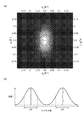
- Fig.3 (a) is a figure which shows an example of the two-dimensional scattering image of the scattering vector q of several CNT assembly 11,11, ... by small angle X ray scattering (SAXS), and FIG.3 (b) is shown.
- 6 is a graph showing an example of an azimuth plot showing the relationship between azimuth angle and scattering intensity of an arbitrary scattering vector q whose origin is the position of transmitted X-ray in a two-dimensional scattering image.
- SAXS is suitable for evaluating structures of several nm to several tens of nm in size.
- the orientation of the CNT 11a having an outer diameter of several nm and the orientation of the CNT aggregate 11 having an outer diameter of several tens nm by analyzing the information of the X-ray scattering image by the following method using SAXS Can be evaluated.
- half value width (DELTA) (theta) of the azimuth angle in the azimuth plot shown in FIG.3 (b) is 48 degrees.
- DELTA half value width
- the CNT wire 10 can adjust the heat radiation route in the longitudinal direction and the cross-sectional direction of the diameter by adjusting the orientation of the CNTs 11 a and the CNT aggregate 11, and therefore, the heat radiation characteristics superior to the metal core wire. Demonstrate.
- orientation refers to the angle difference of the vector of the CNT and the CNT assembly inside with respect to the vector V in the longitudinal direction of the stranded wire produced by twist-collecting CNTs.
- the half width ⁇ of the azimuth angle is 80 ° or less, in the CNT wire 10, the plurality of CNTs 11a, 11a, ... and the plurality of CNT aggregates 11, 11, ... have a certain degree of orientation. It is thought that The upper limit of the half value width ⁇ of the azimuth angle is not particularly limited, but from the viewpoint of enhancing the orientation of the CNTs 11a and the CNT aggregate 11 and further improving the heat dissipation characteristics of the CNT wire 10, 80 ° is preferable and 60 ° is more preferable. And 50 ° are more preferred. The lower limit of the half value width ⁇ of the azimuth angle is not particularly limited, but is preferably 40 ° from the viewpoint of improving the heat dissipation.
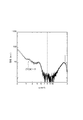
- FIG. 4 is a graph showing the q value-intensity relationship by WAXS (wide-angle X-ray scattering) of the plurality of CNTs 11a, 11a,.
- the CNTs 11a, 11a,... Form a hexagonal close-packed structure in plan view. It can be confirmed. Therefore, the diameter distribution of the plurality of CNT aggregates is narrow in the CNT wire 10, and the plurality of CNTs 11a, 11a,... Form a hexagonal close-packed structure by having a regular arrangement, ie, a high density. It can be said that it exists in high density.
- the plurality of CNT aggregates 11, 11, ... have a good orientation, and further, the plurality of CNTs 11a, 11a, ... constituting the CNT aggregate 11 are regularly arranged. Since the heat of the CNT wire 10 is smoothly transmitted along the longitudinal direction of the CNT aggregate 11 and dissipated, the heat is likely to be dissipated. Therefore, the CNT wire rod 10 can adjust the heat dissipation route in the longitudinal direction and the cross-sectional direction of the diameter by adjusting the arrangement structure and density of the CNT aggregate 11 and the CNTs 11a, so it is superior to a metal core wire. Demonstrates heat dissipation characteristics.
- the peak top q value at the (10) peak of the intensity by X-ray scattering indicating the density of the plurality of CNTs 11a, 11a, ... is 2.0 nm -1 from the viewpoint of further improving the heat dissipation characteristics by obtaining high density.
- above 5.0 nm -1 or less, and is preferably a half-value width [Delta] q (FWHM) is 0.1 nm -1 or 2.0 nm -1 or less.
- the orientation of the CNT aggregate 11 and the CNTs 11a, and the arrangement structure and density of the CNTs 11a are adjusted by appropriately selecting the spinning method such as dry spinning, wet spinning, liquid crystal spinning, and spinning conditions of the spinning method described later. be able to.
- the material used for the insulation coating layer of the covered electric wire which used the metal as a core wire can be used, for example, a thermoplastic resin and a thermosetting resin can be mentioned.
- a thermoplastic resin for example, polytetrafluoroethylene (PTFE) (Young's modulus: 0.4 GPa), polyethylene (Young's modulus: 0.1 to 1.0 GPa), polypropylene (Young's modulus: 1.1 to 1.4 GPa) ), Polyacetal (Young's modulus: 2.8 GPa), polystyrene (Young's modulus: 2.8 to 3.5 GPa), polycarbonate (Young's modulus: 2.5 GPa), polyamide (Young's modulus: 1.1 to 2.9 GPa), Polyvinyl chloride (Young's modulus: 2.5 to 4.2 GPa), polymethyl methacrylate (Young's modulus: 3.2 GPa) polyurethane (Young's modulus: 0.4
- thermosetting resin examples include polyimide (2.1 to 2.8 GPa), phenol resin (5.2 to 7.0 GPa) and the like. These may be used alone or in combination of two or more.
- Young's modulus of the material which comprises the insulation coating layer 21 is not specifically limited, For example, 0.07 GPa or more and 7 GPa or less are preferable, and 0.07 GPa or more and 4 GPa or less are especially preferable.
- the insulating covering layer 21 may be a single layer as shown in FIG. 1, or alternatively, may be two or more layers.
- a layer of a thermosetting resin may be further provided on the insulating covering layer 21 as necessary.
- the thermosetting resin may contain a filler having a fiber shape or a particle shape.
- the ratio of the cross-sectional area in the radial direction of the insulating covering layer 21 to the cross-sectional area in the radial direction of the CNT wire 10 is preferably in the range of 0.01 or more and 1.5 or less.
- the core wire is the CNT wire 10 which is lighter compared to copper, aluminum or the like, and the thickness of the insulating covering layer 21 is thinned. Since it can do, while ensuring insulation reliability fully, the heat dissipation characteristic excellent to the heat of CNT wire material 10 can be acquired.
- weight reduction can be realized as compared with a metal-coated wire such as copper or aluminum.
- the insulating covering layer 21 is coated on the outer peripheral surface of the CNT wire 10 at the ratio of the cross sectional area. Can maintain its shape in the longitudinal direction. Therefore, the handling property at the time of wiring of the CNT coated wire 1 can be enhanced.
- the adhesion between the CNT wire 10 and the insulating coating layer 21 is improved as compared to a coated wire using a core wire of aluminum or copper. Can be improved, and peeling between the CNT wire 10 and the insulating covering layer 21 can be suppressed.
- the ratio of the cross-sectional area is not particularly limited, but is preferably 0.01 or more and 1.5 or less, and from the viewpoint of further improving the insulation reliability, the lower limit thereof is preferably 0.2 and particularly preferably 0.5.
- the upper limit value of the ratio of the cross-sectional area is preferably 1.0 from the viewpoint of further improving the weight saving of the CNT-coated electric wire 1 and the heat dissipation characteristics to the heat of the CNT wire 10.
- the cross-sectional area in the radial direction of the CNT wire 10 is not particularly limited, for example, preferably 0.0005 mm 2 or more 80 mm 2 or less, 0 .0018Mm 2 or 10 mm 2 more preferably less, 0.0018mm 2 or 6.0 mm 2 or less is particularly preferred.
- the cross-sectional area in the radial direction of the insulating covering layer 21 is not particularly limited, it is preferably, for example, 0.002 mm 2 or more and 40 mm 2 or less, and 0.02 mm 2 or more, from the viewpoint of the balance between insulation reliability and heat dissipation. 2 mm 2 or less is particularly preferable.
- the cross-sectional area can be measured, for example, from an image of a scanning electron microscope (SEM) observation. Specifically, after obtaining an SEM image (100 times to 10,000 times) of a radial cross section of the CNT-coated wire 1, the CNT wire 10 was penetrated from the area of the portion surrounded by the outer periphery of the CNT wire 10.
- SEM scanning electron microscope
- the sum of the area obtained by subtracting the area of the material of the insulating covering layer 21, the area of the portion of the insulating covering layer 21 covering the outer periphery of the CNT wire 10 and the area of the material of the insulating covering layer 21 intruding inside the CNT wire 10 is
- the cross-sectional area in the radial direction of the CNT wire 10 and the cross-sectional area in the radial direction of the insulating coating layer 21 are respectively used.
- the radial cross-sectional area of the insulating covering layer 21 also includes the resin that has entered between the CNT wires 10.
- the Young's modulus of CNTs is higher than that of aluminum and copper used as conventional core wires. While the Young's modulus of aluminum is 70.3 GPa and the Young's modulus of copper is 129.8 GPa, the Young's modulus of CNT has a value of about 2 to 10 times or more, 300 to 1500 GPa. Therefore, in the CNT-coated electric wire 1, a material having a high Young's modulus (for example, a thermoplastic resin having a high Young's modulus) is used as the material of the insulating covering layer 21 as compared with the coated electric wire using aluminum or copper as the core wire. As a result, excellent wear resistance can be imparted to the insulating coating layer 21 of the CNT-coated electric wire 1, and the CNT-coated electric wire 1 exerts excellent durability.
- a material having a high Young's modulus for example, a thermoplastic resin having a high Young's modulus
- the Young's modulus of CNT is higher than that of aluminum or copper used as a conventional core wire
- the Young's modulus of the material constituting the insulating coating layer to the Young's modulus of the core is The ratio is smaller than the ratio of the Young's modulus of a coated wire using aluminum or copper as a core wire. Therefore, in the CNT-coated electric wire 1, peeling of the CNT wire 10 and the insulating covering layer 21 and cracking of the insulating covering layer 21 can be suppressed even when being repeatedly bent as compared with the covered electric wire using aluminum or copper as the core wire.
- the ratio of the Young's modulus of the material constituting the insulating coating layer 21 to the Young's modulus of the CNT wire 10 is not particularly limited, but the lower limit of the ratio of the Young's modulus is the CNT wire even if the CNT-coated wire 1 is repeatedly bent. Since the insulating covering layer 21 follows 10 to prevent peeling of the insulating covering layer 21 from the CNT wire 10, 0.00001 is preferable, and even if the CNT-coated wire 1 is bent for a long period of time, from the CNT wire 10 From the viewpoint of preventing the insulation coating layer 21 from peeling, 0.0005 is more preferable, and 0.001 is particularly preferable.
- the upper limit value of the ratio of Young's modulus is preferably 0.5 from the viewpoint of preventing the occurrence of cracks in the insulating covering layer 21 even when the CNT-coated wire 1 is repeatedly bent, 0.1 is more preferable, 0.01 is more preferable, and 0.005 is particularly preferable, from the viewpoint of preventing the occurrence of cracks in the insulating coating layer 21 even when B is bent.
- the Young's modulus of the CNT wire 10 and the Young's modulus of the material constituting the insulating covering layer 21 are obtained by, for example, peeling off the insulating covering layer of the CNT-coated electric wire, and using this as a sample, a tensile test is performed by a method It can be measured by
- the thickness in the direction (that is, the radial direction) orthogonal to the longitudinal direction of the insulating covering layer 21 be uniform in terms of improving the insulation properties and the wear resistance of the CNT-coated electric wire 1.
- the uneven thickness ratio of the insulating coating layer 21 is 50% or more from the point of improving the insulating property and the wear resistance, and is preferably 80% or more from the point of improving the handling property in addition to these.
- the value of the minimum value of the thickness / the maximum value of the thickness of the insulating coating layer 21) ⁇ 100 is calculated, which means a value obtained by averaging the ⁇ values calculated in each cross section.
- the thickness of the insulating covering layer 21 can be measured, for example, from an image of SEM observation by circular approximation of the CNT wire 10.
- the longitudinal center side refers to a region located at the center as viewed from the longitudinal direction of the line.
- the uneven thickness ratio of the insulating covering layer 21 is, for example, in the case of forming the insulating covering layer 21 on the outer peripheral surface of the CNT wire 10 by the extrusion coating method, the longitudinal direction of the CNT wire 10 when passing the CNT wire 10 through a die during the extrusion process. It can be improved by adjusting the tension applied to the When the insulating coating layer 21 is formed by the extrusion coating method, for example, it is preferable to increase the tension applied to the CNT wire 10 so that the die and the CNT wire 10 are continuously coaxial or substantially coaxial.
- the thickness deviation of the insulating covering layer 21 is to increase the roundness of the cross section in the radial direction of the wire if it is a single wire. If it is a stranded wire, it can be improved by increasing the number of twists.
- the number of twists in the case where the CNT wire 10 is a stranded wire is not particularly limited, but is preferably 40 T / m or more and 1500 T / m or less.
- the lower limit value of the number of twists is more preferably 100, and still more preferably 200, in order to obtain sufficient line strength.
- the upper limit value of the number of twists is more preferably 1000, and still more preferably 800, from the viewpoint of suppressing the blurring of the CNT wire 10 due to the stress of retwisting.
- the twist number is less than 40 T / m, the tensile strength of the CNT wire 10 is insufficient, and sufficient tension can not be applied to the CNT wire 10 during the insulation coating process, and the CNT wire 10 passing through the die is Shaking is likely to occur. Therefore, the uneven thickness ratio of the insulating covering layer tends to be low.
- the twist number exceeds 1500 T / m, the tensile strength of the CNT wire 10 is high, and it becomes possible to apply sufficient tension to the CNT wire 10 in the insulation coating process.
- the number of twists exceeds 1500 T / m, the stress of retwisting becomes large, and even if sufficient tension is applied to the CNT wire 10 during the insulation coating process, the blurring of the CNT wire 10 passing through the die is suppressed It is difficult. Therefore, the uneven thickness ratio of the insulating covering layer tends to be low.
- the number of twists is 40 T / m or more and 1500 T / m or less, the thickness deviation of the insulating coating layer is high, and the insulation property is excellent.
- the number of twists is 200 T / m or more and 1000 T / m or less, the thickness deviation of the insulation coating layer tends to be high, and the insulation properties are further excellent.
- the twist number of the CNT wire 10 is 40 T / m or more and 1500 T / m or less, preferably 200 T / m or more and 1000 T / m or less, and further, the CNT wire has a half width ⁇ of azimuth angle of 80 ° or less It is preferable that the thickness deviation of the insulating covering layer is 80% or more.
- the twist number of the CNT wire 10 is 40 T / m or more and 1500 T / m or less, the CNTs are arranged with high density. Further, when the half width ⁇ of the azimuth angle is 80 ° or less, in the CNT wire 10, the CNT aggregate 11 has high orientation.
- the heat of the CNT wire 10 can be easily transmitted along the longitudinal direction, and the CNT wire 10 exhibits excellent heat dissipation characteristics. Furthermore, when the uneven thickness ratio of the insulating coating layer is 80% or more, dielectric breakdown does not easily occur, and the insulating property is excellent.
- the CNT-coated electric wire 1 can be manufactured by first manufacturing the CNTs 11 a, forming the CNT wire 10 from the obtained plurality of CNTs 11 a, and coating the outer circumferential surface of the CNT wire 10 with the insulating covering layer 21.
- the CNTs 11a can be manufactured by a method such as a floating catalyst method (Japanese Patent No. 5819888) or a substrate method (Japanese Patent No. 5590603).
- the strands of the CNT wire 10 are, for example, dry spinning (Japanese Patent No. 5819888, Patent No. 5990202, Japanese Patent No. 5350635), wet spinning (Japanese Patent No. 5135620, Japanese Patent No. 5131571, Japanese Patent No. 5288359), liquid crystal spinning (Japanese Patent Application Publication No. 2014-530964) and the like.
- the orientation of the CNT aggregate 11 constituting the CNT wire 10 or the orientation of the CNTs 11a constituting the CNT aggregate 11 is determined by, for example, a spinning method such as dry spinning, wet spinning, liquid crystal spinning and the like. It can adjust by selecting conditions and suitably.
- twist number can be represented by a value (unit: T / m) obtained by dividing the number of twists (T) by the length of the line (m).
- a method of covering an insulating covering layer on a core wire of aluminum or copper can be used.
- a raw material of the insulating covering layer 21 The method of melt
- the CNT-coated electric wire 1 can be used as a general electric wire such as a wire harness, and a cable may be produced from a general electric wire using the CNT-coated electric wire 1.
- the coil may be produced by winding the CNT-coated wire 1.
- the space factor is preferably 60% or more.
- the coil can be used for various motors and the like, but it is particularly preferable to use the coil for precision equipment, medical equipment, portable devices and the like from the viewpoint of heat dissipation and lightness.
- an insulating coating layer is formed by extrusion coating around the conductor using a general wire extrusion extruder,
- the CNT-coated electric wire used in the example of Table 1 shown below and a comparative example was produced.
- the thickness deviation was adjusted by changing the tension applied to the CNT wire.
- (C) Twist number of CNT wire In each of Examples 2 to 10, 12 to 15, 17 to 20, and Comparative Examples 1 to 3, the CNT wire is formed by bundling a plurality of strands and fixing one end, the other end was twisted a predetermined number of times to make a stranded wire.
- the twist number is represented by a value (unit: T / m) obtained by dividing the number of twists (T) by the length of the line (m).
- the uneven thickness ratio of the insulation coating layer in the CNT-coated electric wire is 50% or more, and all of the heat dissipation, bending resistance, wear resistance and insulation reliability are all It was good.
- the uneven thickness ratio of the insulating coating layer in the CNT-coated electric wire was 60% or more and 79% or less, and the wear resistance and the insulation reliability were more favorable.
- the CNT-coated electric wire Examples 4, 5, 9, 10, 17, 19, 20
- the uneven thickness ratio of the insulating covering layer is 80% or more
- the abrasion resistance and the insulation reliability were excellent.
- the coil has a high space factor.
- the half value width ⁇ of the azimuth angle was 40 ° or more and 75 ° or less. Therefore, in the CNT-coated electric wires of Examples 1 to 20, the CNT assembly had excellent orientation. In particular, in Example 6, since the half value width ⁇ of the azimuth angle is as small as 55 °, the heat dissipation was excellent. Further, in Examples 1 to 5 and 8 to 20, since the half value width ⁇ of the azimuth angle was as small as 40 °, the heat dissipation was better.
- Examples 1 ⁇ 20 q values of the peak top in (10) peak intensity are both at 2.0 nm -1 or 5.0 nm -1 or less, the half width ⁇ q are all 0.1nm -1 or more and 2.0 nm -1 or less. Therefore, in the CNT-coated electric wires of Examples 1 to 20, the CNTs were present at a high density.
- Comparative Example 1 the uneven thickness ratio of the insulating coating layer was 42%, and both the wear resistance and the insulation reliability were inferior.
- Comparative Example 2 the uneven thickness ratio of the insulating coating layer was 38%, and the winding was not stable when processed into a coil. The space factor of the coil became low due to poor handling.
- Comparative Example 3 the uneven thickness ratio of the insulating coating layer was 41%, and both of the abrasion resistance and the insulation reliability were inferior.
- the conductor was a copper wire or an aluminum wire, and the bending resistance was inferior.
Abstract
The present invention pertains to a carbon nanotube coated electric wire and a coil, whereby excellent insulation and abrasion resistance can be achieved while having excellent conductivity comparable to a wire material comprising copper or aluminum, etc., and whereby both excellent heat dissipation and weight reduction can be achieved. The carbon nanotube coated electric wire (1) comprises: a carbon nanotube wire material (10) comprising at least one carbon nanotube aggregate (11) comprising a plurality of carbon nanotubes (11a); and an insulating coating layer (21) that coats the carbon nanotube wire material. The insulating coating layer (21) has an uneven thickness rate of at least 50%.
Description
本発明は、複数のカーボンナノチューブで構成されるカーボンナノチューブ線材を絶縁材料で被覆したカーボンナノチューブ被覆電線及びコイルに関するものである。
The present invention relates to a carbon nanotube coated wire and coil in which a carbon nanotube wire composed of a plurality of carbon nanotubes is coated with an insulating material.
カーボンナノチューブ(以下、「CNT」ということがある。)は、様々な特性を有する素材であり、多くの分野への応用が期待されている。
Carbon nanotubes (hereinafter sometimes referred to as "CNT") are materials having various properties, and their application in many fields is expected.
例えば、CNTは、六角形格子の網目構造を有する筒状体の単層、または略同軸で配された多層で構成される3次元網目構造体であり、軽量であると共に、導電性、熱伝導性、機械的強度等の諸特性に優れる。しかし、CNTを線材化することは容易ではなく、CNTを線材として利用する技術は提案されていない。
For example, CNT is a single layer of a tubular body having a network structure of a hexagonal lattice, or a three-dimensional network structure composed of multiple layers arranged substantially coaxially, which is lightweight, conductive, and thermally conductive. Excellent in various properties such as flexibility and mechanical strength. However, it is not easy to wire CNTs, and no technology has been proposed for utilizing CNTs as wires.
数少ないCNT線を利用した技術の例として、多層配線構造に形成されるビアホールの埋め込み材料である金属の代替として、CNTを使用することが検討されている。具体的には、多層配線構造の低抵抗化のために、多層CNTの成長基点から遠い側の端部へ同心状に伸延した多層CNTの複数の切り口を導電層にそれぞれ接触させた多層CNTを、2以上の導電層の層間配線として使用した配線構造が提案されている(特許文献1)。
As an example of a technology using a few CNT lines, using CNT as a substitute for metal which is a filling material of a via hole formed in a multilayer wiring structure is considered. Specifically, in order to reduce the resistance of the multilayer wiring structure, multilayer CNTs in which a plurality of incisions of the multilayer CNT concentrically extended to the end far from the growth origin of the multilayer CNT are brought into contact with the conductive layer A wiring structure used as an interlayer wiring of two or more conductive layers has been proposed (Patent Document 1).
その他の例として、CNT材料の導電性をさらに向上させるために、隣接したCNT線材の電気的接合点に、金属等からなる導電性堆積物を形成したCNT材料が提案されている。このようなCNT材料は広汎な用途に適用できることが開示されている(特許文献2)。また、CNT線材の有する優れた熱伝導性から、CNTのマトリクスから作られた熱伝導部材を有する加熱器が提案されている(特許文献3)。
As another example, in order to further improve the conductivity of the CNT material, a CNT material is proposed in which a conductive deposit made of metal or the like is formed at the electrical junction of adjacent CNT wires. It is disclosed that such a CNT material can be applied to a wide range of applications (Patent Document 2). Moreover, the heater which has a thermally-conductive member made from the matrix of CNT is proposed from the outstanding thermal conductivity which a CNT wire has (patent document 3).
一方で、自動車や産業機器などの様々な分野における電力線や信号線として、一又は複数の線材からなる芯線と、該芯線を被覆する絶縁被覆とからなる電線が用いられている。芯線を構成する線材の材料としては、通常、電気特性の観点から銅又は銅合金が使用されるが、近年、軽量化の観点からアルミニウム又はアルミニウム合金が提案されている。例えば、アルミニウムの比重は銅の比重の約1/3、アルミニウムの導電率は銅の導電率の約2/3(純銅を100%IACSの基準とした場合、純アルミニウムは約66%IACS)であり、アルミニウム線材に、銅線材と同じ電流を流すためには、アルミニウム線材の断面積を、銅線材の断面積の約1.5倍と大きくする必要があるが、そのように断面積を大きくしたアルミニウム線材を用いたとしても、アルミニウム線材の質量は、銅線材の質量の半分程度であることから、アルミニウム線材を使用することは、軽量化の観点から有利である。
On the other hand, as a power line or signal line in various fields such as automobiles and industrial equipment, an electric wire made of a core wire made of one or a plurality of wires and an insulation coating which covers the core wire is used. As a material of the wire which comprises a core wire, although a copper or copper alloy is usually used from a viewpoint of an electrical property, aluminum or an aluminum alloy is proposed from a viewpoint of weight reduction in recent years. For example, the specific gravity of aluminum is about 1/3 of the specific gravity of copper, and the conductivity of aluminum is about 2/3 of that of copper (based on 100% IACS for pure copper, about 66% IACS for pure aluminum) There is a need to increase the cross-sectional area of the aluminum wire to about 1.5 times the cross-sectional area of the copper wire in order to flow the same current as the copper wire to the aluminum wire. Even if the aluminum wire is used, since the mass of the aluminum wire is about half of the mass of the copper wire, using the aluminum wire is advantageous from the viewpoint of weight reduction.
また、自動車、産業機器等の高性能化・高機能化が進められており、これに伴い、各種電気機器、制御機器などの配設数が増加するとともに、これら機器に使用される電気配線体の配線数と芯線からの発熱も増加する傾向にある。そこで、絶縁被覆による絶縁性を損なうことなく、電線の放熱特性を向上させることが要求されている。また、その一方で、環境対応のために自動車等の移動体の燃費を向上させるため、線材の軽量化も要求されている。
In addition, with the advancement of performance and functionality of automobiles, industrial equipment, etc., along with this, the number of installation of various electrical equipments, control equipments, etc. increases, and electric wiring bodies used for these equipments The number of wires and heat generation from the core tend to increase. Therefore, it is required to improve the heat radiation characteristics of the electric wire without impairing the insulation property by the insulation coating. On the other hand, in order to improve the fuel consumption of moving bodies such as automobiles for environmental protection, weight reduction of the wire is also required.
また、被覆電線は、一般に、押出成形機などを用いて導体の外周面に絶縁被覆層を押出被覆することにより製造される。導体を被覆する絶縁被覆層は、押出工程で使用するダイスの形状により、所望の厚さで形成される。CNT線は高いヤング率を有し、CNT線を撚り線とした場合には撚り戻りの応力が生じやすい。そのため、CNT線に対して絶縁被覆処理を行う際、特にダイスにCNT線を通過させる際にぶれが生じやすい。ぶれを抑制するには、CNT線に十分な張力を加えて絶縁被覆処理を行えばよいが、引張強度の小さいCNT線に対してはあまり張力を加えることができない。絶縁被覆処理においてぶれが生じると、絶縁被覆層の厚さにばらつきが生じる、すなわち絶縁被覆層の偏肉率が低くなるといった問題がある。絶縁被覆層の厚さが薄い箇所では絶縁破壊が起こりやすいことから、絶縁性に優れたCNT被覆電線の開発が望まれている。
In addition, a coated wire is generally manufactured by extrusion-coating an insulating coating layer on the outer peripheral surface of a conductor using an extrusion molding machine or the like. The insulating covering layer covering the conductor is formed to a desired thickness depending on the shape of the die used in the extrusion process. The CNT wire has a high Young's modulus, and when the CNT wire is a stranded wire, a stress of re-twisting easily occurs. Therefore, when performing the insulation coating process with respect to a CNT line | wire, especially when passing a CNT line | wire to dice | dies, it is easy to produce blurring. In order to suppress blurring, sufficient tension may be applied to the CNT wire to perform the insulation coating treatment, but tension can not be applied so much to the CNT wire with low tensile strength. If blurring occurs in the insulation coating process, the thickness of the insulation coating layer may vary, that is, the uneven thickness ratio of the insulation coating layer may be reduced. Development of a CNT-coated electric wire having excellent insulation properties is desired because dielectric breakdown is likely to occur at a portion where the thickness of the insulating covering layer is thin.
本発明は、銅やアルミニウム等からなる線材に匹敵する優れた導電性を有しつつ、優れた絶縁性及び耐摩耗性を実現し、更には放熱性に優れ且つ軽量化を実現することができるカーボンナノチューブ被覆電線及びコイルを提供することを目的とする。
The present invention achieves excellent insulation and wear resistance while having excellent conductivity comparable to a wire made of copper, aluminum or the like, and can further realize excellent heat dissipation and weight reduction. It is an object of the present invention to provide a carbon nanotube coated wire and coil.
上記目的を達成するために、本発明のカーボンナノチューブ被覆電線は、複数のカーボンナノチューブで構成されるカーボンナノチューブ集合体の単数または複数からなるカーボンナノチューブ線材と、該カーボンナノチューブ線材を被覆する絶縁被覆層と、を備え、前記絶縁被覆層の偏肉率が50%以上である。
In order to achieve the above object, a carbon nanotube-coated electric wire of the present invention comprises a carbon nanotube wire comprising one or more carbon nanotube aggregates composed of a plurality of carbon nanotubes, and an insulating coating layer covering the carbon nanotube wire. And the uneven thickness ratio of the insulating covering layer is 50% or more.
また、前記絶縁被覆層の偏肉率が80%以上であるのが好ましい。
Moreover, it is preferable that the uneven thickness rate of the said insulation coating layer is 80% or more.
前記カーボンナノチューブ線材の撚り数が40T/m以上1500T/m以下であるのが好ましい。
The twist number of the carbon nanotube wire is preferably 40 T / m or more and 1,500 T / m or less.
前記カーボンナノチューブ線材の撚り数が200T/m以上1000T/m以下であるのが好ましい。
The number of twists of the carbon nanotube wire is preferably 200 T / m or more and 1000 T / m or less.
前記カーボンナノチューブ線材が、複数の前記カーボンナノチューブ集合体からなり、複数の該カーボンナノチューブ集合体の配向性を示す小角X線散乱によるアジマスプロットにおけるアジマス角の半値幅Δθが80°以下であり、かつ、前記絶縁被覆層の偏肉率が80%以上であるのが好ましい。
The carbon nanotube wire is composed of a plurality of the aggregate of carbon nanotubes, and the half width Δθ of an azimuth angle in an azimuth plot by small angle X-ray scattering showing the orientation of the plurality of aggregate of carbon nanotubes is 80 ° or less Preferably, the uneven thickness ratio of the insulating covering layer is 80% or more.
前記アジマス角の半値幅Δθが60°以下であるのが好ましい。
The half width Δθ of the azimuth angle is preferably 60 ° or less.
前記カーボンナノチューブ線材の径方向の断面積に対する前記絶縁被覆層の径方向の断面積の比率が、0.01以上1.5以下であるのが好ましい。
The ratio of the cross-sectional area in the radial direction of the insulating covering layer to the cross-sectional area in the radial direction of the carbon nanotube wire is preferably 0.01 or more and 1.5 or less.
前記カーボンナノチューブ線材の径方向の断面積が、0.0005mm2以上80mm2以下であるのが好ましい。
Sectional area of the radial direction of the carbon nanotube wire is is preferably a 0.0005 mm 2 or more 80 mm 2 or less.
前記カーボンナノチューブ線材のヤング率に対する前記絶縁被覆層を構成する材料のヤング率の比率が、0.00001以上0.5以下であるのが好ましい。
It is preferable that the ratio of the Young's modulus of the material which comprises the said insulation coating layer with respect to the Young's modulus of the said carbon nanotube wire is 0.00001 or more and 0.5 or less.
前記カーボンナノチューブ線材のヤング率に対する前記絶縁被覆層を構成する材料のヤング率の比率が、0.0005以上0.1以下であるのが好ましい。
It is preferable that the ratio of the Young's modulus of the material which comprises the said insulation coating layer with respect to the Young's modulus of the said carbon nanotube wire is 0.0005 or more and 0.1 or less.
前記カーボンナノチューブ線材が、複数の前記カーボンナノチューブ集合体からなり、複数の該カーボンナノチューブ集合体の配向性を示す小角X線散乱によるアジマスプロットにおけるアジマス角の半値幅Δθが40°以上であるのが好ましい。
The carbon nanotube wire is composed of a plurality of the aggregate of carbon nanotubes, and the half width Δθ of azimuth angle in an azimuth plot by small angle X-ray scattering showing the orientation of the plurality of aggregate of carbon nanotubes is 40 ° or more preferable.
複数の前記カーボンナノチューブの密度を示すX線散乱による散乱強度の(10)ピークにおけるピークトップのq値が2.0nm-1以上5.0nm-1以下であり、且つ半値幅Δqが0.1nm-1以上2.0nm-1以下であるのが好ましい。
Q value of the peak top in (10) the peak of scattering intensity by X-ray scattering shows a density of a plurality of the carbon nanotubes is at 2.0 nm -1 or 5.0 nm -1 or less, and the half-value width Δq is 0.1nm It is preferable that the wavelength is -1 or more and 2.0 nm -1 or less.
本発明のコイルは、カーボンナノチューブ被覆電線を巻回することにより形成されるのが好ましい。
The coil of the present invention is preferably formed by winding a carbon nanotube coated wire.
芯線としてカーボンナノチューブを使用したカーボンナノチューブ線材は、金属製の芯線とは異なり、熱伝導に異方性があり、径方向と比較して長手方向に優先的に熱が伝導する。すなわち、カーボンナノチューブ線材には、放熱特性に異方性があるため、金属製の芯線と比較して優れた放熱性を備えている。そのため、カーボンナノチューブを使用した芯線に被覆する絶縁被覆層の設計は、金属製の芯線の絶縁被覆層とは異なる設計とすることが必要になる。本発明によれば、絶縁被覆層の偏肉率が50%以上であるので、カーボンナノチューブ線材が偏肉し易い撚り線などの構成であっても、絶縁破壊の発生を抑制することができ、優れた絶縁性を実現することができる。また、カーボンナノチューブ被覆電線の優れた耐摩耗性を実現することができ、さらに、銅やアルミニウムなどの金属被覆電線と比較して軽量化を実現することができる。
Unlike a metal core wire, a carbon nanotube wire using a carbon nanotube as a core wire is anisotropic in thermal conduction, and heat is preferentially conducted in the longitudinal direction as compared with the radial direction. That is, since the carbon nanotube wire has anisotropic heat dissipation characteristics, it has excellent heat dissipation as compared to a metal core wire. Therefore, the design of the insulating covering layer for covering the core wire using carbon nanotubes needs to be designed differently from the insulating covering layer of the metal core wire. According to the present invention, since the uneven thickness ratio of the insulating coating layer is 50% or more, the occurrence of dielectric breakdown can be suppressed even if the carbon nanotube wire has a configuration such as a stranded wire which is easily uneven. Excellent insulation can be realized. In addition, the excellent abrasion resistance of the carbon nanotube-coated wire can be realized, and further, the weight reduction can be realized as compared with a metal-coated wire such as copper or aluminum.
また、絶縁被覆層の偏肉率が80%以上であることにより、より均一な絶縁被覆層が形成され、カーボンナノチューブ被覆電線が長手方向に関して曲がりにくくなり、設備或いは装置における電線路の形成時に容易に配索することができ、優れた絶縁性及び優れたハンドリング性を両立することができる。
In addition, when the uneven thickness ratio of the insulating covering layer is 80% or more, a more uniform insulating covering layer is formed, the carbon nanotube coated electric wire becomes difficult to bend in the longitudinal direction, and it is easy at the time of forming the electric line in equipment or equipment. Thus, it is possible to arrange the wires and to achieve both the excellent insulation and the excellent handling.
また、カーボンナノチューブ線材の撚り数が40T/m以上1500T/m以下であることにより、カーボンナノチューブ線材の引張強度が高まり、CNT線に十分な張力を加えた状態で絶縁被覆処理を行うことができる。その結果、絶縁被覆層の偏肉率が高くなる。絶縁破壊の発生を抑制することができ、優れた絶縁性を実現することができる。
In addition, when the number of twists of the carbon nanotube wire is 40 T / m or more and 1500 T / m or less, the tensile strength of the carbon nanotube wire is increased, and the insulation coating process can be performed in a state where sufficient tension is applied to the CNT wire. . As a result, the uneven thickness ratio of the insulating covering layer becomes high. The occurrence of dielectric breakdown can be suppressed, and excellent insulation can be realized.
さらに、カーボンナノチューブ線材が、複数の前記カーボンナノチューブ集合体からなり、複数の該カーボンナノチューブ集合体の配向性を示す小角X線散乱によるアジマスプロットにおけるアジマス角の半値幅Δθが80°以下であり、かつ、絶縁被覆層の偏肉率が80%以上であることにより、優れた放熱性と絶縁性を両立することができる。
Furthermore, a carbon nanotube wire is composed of a plurality of the aggregate of carbon nanotubes, and the half width Δθ of an azimuth angle in an azimuth plot by small angle X-ray scattering showing the orientation of the plurality of aggregate of carbon nanotubes is 80 ° or less. And when the thickness deviation of an insulation coating layer is 80% or more, the outstanding heat dissipation and insulation can be compatible.
また、前記カーボンナノチューブ線材の径方向の断面積に対する前記絶縁被覆層の径方向の断面積の比率が、0.01以上1.5以下であることにより、偏肉し易い薄肉の絶縁被覆層が形成される場合にも、絶縁性を損なうことなく優れた耐摩耗性を実現することができ、加えて更なる軽量化を実現することができる。
In addition, when the ratio of the cross-sectional area in the radial direction of the insulating coating layer to the cross-sectional area in the radial direction of the carbon nanotube wire is 0.01 or more and 1.5 or less, the thin insulating coating layer is easily uneven. Even when formed, excellent wear resistance can be realized without losing insulation, and further weight reduction can be realized.
また、カーボンナノチューブ線材のヤング率に対する絶縁被覆層を構成する材料のヤング率の比率が0.00001以上0.5以下であることにより、カーボンナノチューブ被覆電線を繰り返し屈曲させても、カーボンナノチューブ線材から絶縁被覆層が剥離したり、絶縁被覆層に割れが生じることを確実に防止できる。
In addition, since the ratio of the Young's modulus of the material constituting the insulating coating layer to the Young's modulus of the carbon nanotube wire is 0.00001 or more and 0.5 or less, even if the carbon nanotube coated electric wire is bent repeatedly, from the carbon nanotube wire It is possible to reliably prevent peeling of the insulating coating layer and cracking of the insulating coating layer.
更に、カーボンナノチューブ線材におけるカーボンナノチューブ集合体の、小角X線散乱によるアジマスプロットにおけるアジマス角の半値幅Δθが40°以上であることにより、カーボンナノチューブ線材においてカーボンナノチューブ集合体が高い配向性を有するので、カーボンナノチューブ線材の放熱特性がさらに向上する。
Furthermore, the carbon nanotube aggregate in the carbon nanotube wire has high orientation because the half width Δθ of the azimuth angle in the azimuth plot by small angle X-ray scattering of the carbon nanotube aggregate in the carbon nanotube wire is 40 ° or more. The heat dissipation characteristics of the carbon nanotube wire are further improved.
更に、配列したカーボンナノチューブのX線散乱による散乱強度の(10)ピークにおけるピークトップのq値が2.0nm-1以上5.0nm-1以下であり、且つ半値幅Δqが0.1nm-1以上2.0nm-1以下であることにより、カーボンナノチューブが高密度で存在しうるので、カーボンナノチューブ線材の放熱特性がさらに向上する。
Furthermore, q values of the peak top in (10) the peak of scattering intensity by X-ray scattering of aligned carbon nanotubes is at 2.0 nm -1 or 5.0 nm -1 or less, and the half-value width Δq is 0.1 nm -1 When the thickness is 2.0 nm −1 or less, carbon nanotubes can be present at high density, and thus the heat dissipation characteristics of the carbon nanotube wire are further improved.
以下、本発明の実施形態に係るカーボンナノチューブ被覆電線を、図面を参照しながら説明する。
Hereinafter, a carbon nanotube coated electric wire according to an embodiment of the present invention will be described with reference to the drawings.
[カーボンナノチューブ被覆電線の構成]
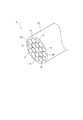
図1に示すように、本発明の実施形態に係るカーボンナノチューブ被覆電線(以下、「CNT被覆電線」ということがある。)1は、カーボンナノチューブ線材(以下、「CNT線材」ということがある。)10の外周面に絶縁被覆層21が被覆された構成となっている。すなわち、CNT線材10の長手方向に沿って絶縁被覆層21が被覆されている。CNT被覆電線1では、CNT線材10の外周面全体が、絶縁被覆層21によって被覆されている。また、CNT被覆電線1では、絶縁被覆層21はCNT線材10の外周面と直接接した態様となっている。図1では、CNT線材10は、1本のCNT線材10からなる素線(単線)となっているが、CNT線材10は、複数本のCNT線材10を撚り合わせた撚り線の状態でもよい。CNT線材10を撚り線の形態とすることで、CNT線材10の円相当直径や断面積を適宜調節することができる。 [Composition of carbon nanotube coated wire]
As shown in FIG. 1, a carbon nanotube coated electric wire (hereinafter sometimes referred to as "CNT coated electric wire") 1 according to an embodiment of the present invention is sometimes referred to as a carbon nanotube wire (hereinafter referred to as a "CNT wire"). The outer peripheral surface of 10) 10 is covered with the insulatingcovering layer 21. That is, the insulating coating layer 21 is coated along the longitudinal direction of the CNT wire 10. In the CNT-coated electric wire 1, the entire outer peripheral surface of the CNT wire 10 is covered with the insulating covering layer 21. Further, in the CNT-coated electric wire 1, the insulating covering layer 21 is in an aspect in direct contact with the outer peripheral surface of the CNT wire 10. In FIG. 1, the CNT wire 10 is a strand (single wire) formed of one CNT wire 10. However, the CNT wire 10 may be in the form of a stranded wire obtained by twisting a plurality of CNT wires 10. By setting the CNT wire 10 in the form of a stranded wire, the equivalent circle diameter and the cross-sectional area of the CNT wire 10 can be appropriately adjusted.
図1に示すように、本発明の実施形態に係るカーボンナノチューブ被覆電線(以下、「CNT被覆電線」ということがある。)1は、カーボンナノチューブ線材(以下、「CNT線材」ということがある。)10の外周面に絶縁被覆層21が被覆された構成となっている。すなわち、CNT線材10の長手方向に沿って絶縁被覆層21が被覆されている。CNT被覆電線1では、CNT線材10の外周面全体が、絶縁被覆層21によって被覆されている。また、CNT被覆電線1では、絶縁被覆層21はCNT線材10の外周面と直接接した態様となっている。図1では、CNT線材10は、1本のCNT線材10からなる素線(単線)となっているが、CNT線材10は、複数本のCNT線材10を撚り合わせた撚り線の状態でもよい。CNT線材10を撚り線の形態とすることで、CNT線材10の円相当直径や断面積を適宜調節することができる。 [Composition of carbon nanotube coated wire]
As shown in FIG. 1, a carbon nanotube coated electric wire (hereinafter sometimes referred to as "CNT coated electric wire") 1 according to an embodiment of the present invention is sometimes referred to as a carbon nanotube wire (hereinafter referred to as a "CNT wire"). The outer peripheral surface of 10) 10 is covered with the insulating
図2に示すように、CNT線材10は、1層以上の層構造を有する複数のCNT11a,11a,・・・で構成されるカーボンナノチューブ集合体(以下、「CNT集合体」ということがある。)11の単数から、または複数が束ねられて形成されている。ここで、CNT線材とはCNTの割合が90質量%以上のCNT線材を意味する。なお、CNT線材におけるCNT割合の算定においては、メッキやドーパントの質量は除く。図2では、CNT線材10は、CNT集合体11が、複数、束ねられた構成となっている。CNT集合体11の長手方向が、CNT線材10の長手方向を形成している。従って、CNT集合体11は、線状となっている。CNT線材10における複数のCNT集合体11,11,・・・は、その長軸方向がほぼ揃って配されている。従って、CNT線材10における複数のCNT集合体11,11,・・・は、配向している。素線であるCNT線材10の円相当直径は、特に限定されないが、例えば、0.01mm以上4mm以下である。また、撚り線としたCNT線材10の円相当直径は、特に限定されないが、例えば、0.1mm以上15mm以下である。
As shown in FIG. 2, the CNT wire 10 is sometimes referred to as a carbon nanotube assembly (hereinafter referred to as "CNT assembly") composed of a plurality of CNTs 11a, 11a, ... having a layer structure of one or more layers. 11) It is formed by bundling one or more of eleven. Here, the CNT wire means a CNT wire having a ratio of CNT of 90% by mass or more. In addition, in calculation of the CNT ratio in a CNT wire, the mass of plating and a dopant is remove | excluded. In FIG. 2, the CNT wire 10 has a configuration in which a plurality of CNT assemblies 11 are bundled. The longitudinal direction of the CNT assembly 11 forms the longitudinal direction of the CNT wire 10. Therefore, the CNT assembly 11 is linear. The plurality of CNT aggregates 11, 11,... In the CNT wire 10 are arranged substantially in the same longitudinal direction. Therefore, the plurality of CNT aggregates 11, 11, ... in the CNT wire 10 are oriented. Although the equivalent circle diameter of the CNT wire 10 which is a strand is not specifically limited, For example, they are 0.01 mm or more and 4 mm or less. Further, the equivalent circle diameter of the twisted CNT wire 10 is not particularly limited, and is, for example, 0.1 mm or more and 15 mm or less.
CNT線材10のヤング率は、例えば、300~1500GPaである。また、CNT線材10が素線(単線)である場合、CNT線材10のヤング率は、例えば、600~1500GPaであり、CNT線材10が撚り線である場合、CNT線材10のヤング率は、例えば300~1200GPaである。
The Young's modulus of the CNT wire 10 is, for example, 300 to 1,500 GPa. When the CNT wire 10 is a strand (single wire), the Young's modulus of the CNT wire 10 is, for example, 600 to 1500 GPa, and when the CNT wire 10 is a stranded wire, the Young's modulus of the CNT wire 10 is, for example, It is 300 to 1200 GPa.
CNT集合体11は、1層以上の層構造を有するCNT11aの束である。CNT11aの長手方向が、CNT集合体11の長手方向を形成している。CNT集合体11における複数のCNT11a,11a,・・・は、その長軸方向がほぼ揃って配されている。従って、CNT集合体11における複数のCNT11a,11a,・・・は、配向している。CNT集合体11の円相当直径は、例えば、20nm以上1000nm以下であり、より典型的には、20nm以上80nm以下である。CNT11aの最外層の幅寸法は、例えば、1.0nm以上5.0nm以下である。
The CNT assembly 11 is a bundle of CNTs 11 a having a layer structure of one or more layers. The longitudinal direction of the CNTs 11 a forms the longitudinal direction of the CNT assembly 11. The plurality of CNTs 11a, 11a,... In the CNT assembly 11 are arranged substantially in the same longitudinal direction. Therefore, the plurality of CNTs 11a, 11a,... In the CNT aggregate 11 are oriented. The equivalent circle diameter of the CNT assembly 11 is, for example, 20 nm or more and 1000 nm or less, and more typically 20 nm or more and 80 nm or less. The width dimension of the outermost layer of the CNTs 11 a is, for example, 1.0 nm or more and 5.0 nm or less.
CNT集合体11を構成するCNT11aは、単層構造又は多層構造を有する筒状体であり、それぞれ、SWNT(single-walled nanotube)、MWNT(multi-walled nanotube)と呼ばれる。図2では、便宜上、2層構造を有するCNT11aのみを記載しているが、CNT集合体11には、3層構造以上の層構造を有するCNTや単層構造の層構造を有するCNTも含まれていてもよく、3層構造以上の層構造を有するCNTまたは単層構造の層構造を有するCNTから形成されていてもよい。
The CNTs 11a constituting the CNT assembly 11 are cylindrical bodies having a single layer structure or a multilayer structure, and are respectively called SWNT (single-walled nanotubes) and MWNT (multi-walled nanotubes). In FIG. 2, for convenience, only the CNTs 11 a having a two-layer structure are described, but the CNT aggregate 11 includes CNTs having a three-layer structure or more and a CNT having a single-layer structure. It may be formed of CNT having a layer structure of three or more layer structure or CNT having a layer structure of single layer structure.
2層構造を有するCNT11aでは、六角形格子の網目構造を有する2つの筒状体T1、T2が略同軸で配された3次元網目構造体となっており、DWNT(Double-walled nanotube)と呼ばれる。構成単位である六角形格子は、その頂点に炭素原子が配された六員環であり、他の六員環と隣接してこれらが連続的に結合している。
The CNT 11a having a two-layer structure is a three-dimensional network structure in which two cylindrical bodies T1 and T2 having a network structure of a hexagonal lattice are arranged substantially coaxially, and is called DWNT (Double-walled nanotube) . The hexagonal lattice, which is a structural unit, is a six-membered ring having a carbon atom at its apex, and adjacent to another six-membered ring, these are continuously bonded.
CNT11aの性質は、上記筒状体のカイラリティ(chirality)に依存する。カイラリティは、アームチェア型、ジグザグ型、及びカイラル型に大別され、アームチェア型は金属性、ジグザグ型は半導体性および半金属性、カイラル型は半導体性および半金属性の挙動を示す。従って、CNT11aの導電性は、筒状体がいずれのカイラリティを有するかによって大きく異なる。CNT被覆電線1のCNT線材10を構成するCNT集合体11では、導電性をさらに向上させる点から、金属性の挙動を示すアームチェア型のCNT11aの割合を増大させることが好ましい。
The properties of the CNTs 11a depend on the chirality of the above-mentioned cylindrical body. The chirality is roughly classified into an armchair type, a zigzag type, and a chiral type. The armchair type is metallic, the zigzag type is semiconductive and semimetallic, and the chiral type is semiconductive and semimetallic. Therefore, the conductivity of the CNTs 11a largely differs depending on which chirality the tubular body has. In the CNT aggregate 11 constituting the CNT wire 10 of the CNT-coated electric wire 1, it is preferable to increase the proportion of armchair-type CNTs 11a exhibiting metallic behavior, in order to further improve the conductivity.
一方で、半導体性の挙動を示すカイラル型のCNT11aに電子供与性もしくは電子受容性を持つ物質(異種元素)をドープすることにより、カイラル型のCNT11aが金属的挙動を示すことが分かっている。また、一般的な金属では、異種元素をドープすることによって金属内部での伝導電子の散乱が起こって導電性が低下するが、これと同様に、金属性の挙動を示すCNT11aに異種元素をドープした場合には、導電性の低下を引き起こす。
On the other hand, it is known that the chiral CNTs 11a exhibit metallic behavior by doping the chiral CNTs 11a exhibiting a semiconducting behavior with a material having an electron donating property or an electron accepting property (different element). In addition, in general metals, the doping of different elements causes scattering of conduction electrons inside the metal to lower the conductivity, but similar to this, the CNT 11a showing metallic behavior is doped with different elements. If it does, it causes a decrease in conductivity.
このように、金属性の挙動を示すCNT11a及び半導体性の挙動を示すCNT11aへのドーピング効果は、導電性の観点からはトレードオフの関係にあることから、理論的には金属性の挙動を示すCNT11aと半導体性の挙動を示すCNT11aとを別個に作製し、半導体性の挙動を示すCNT11aにのみドーピング処理を施した後、これらを組み合わせることが望ましい。しかし、現状の製法技術では、金属性の挙動を示すCNT11aと半導体性の挙動を示すCNT11aとを選択的に作り分けることは困難であり、金属性の挙動を示すCNT11aと半導体性の挙動を示すCNT11aが混在した状態で作製される。このため、金属性の挙動を示すCNT11aと半導体性の挙動を示すCNT11aの混合物からなるCNT線材10の導電性をさらに向上させるために、異種元素・分子によるドーピング処理が効果的となるCNT11aの層構造を選択することが好ましい。
Thus, the doping effects on the CNTs 11a showing the behavior of the metal and the CNTs 11a showing the behavior of the semiconductivity are in a trade-off relationship from the viewpoint of the conductivity, and thus the behavior of the metal theoretically appears. It is desirable that the CNTs 11a and the CNTs 11a exhibiting the behavior of the semiconductor property are separately manufactured, and the doping process is performed only on the CNTs 11a exhibiting the behavior of the semiconductor property, and then these are combined. However, it is difficult to selectively make the CNT 11a showing metallic behavior and the CNT 11a showing semiconducting behavior selectively with the current manufacturing technology, and exhibits the behavior of the semiconducting and CNT 11a showing metallic behavior It is produced in a state in which the CNTs 11a are mixed. Therefore, in order to further improve the conductivity of the CNT wire 10 composed of a mixture of CNTs 11a exhibiting metallic behavior and CNTs 11a exhibiting semiconducting behavior, a layer of CNTs 11a in which doping treatment with different elements and molecules is effective It is preferred to select the structure.
例えば、2層構造又は3層構造のような層数が少ないCNTは、それより層数の多いCNTよりも比較的導電性が高く、ドーピング処理を施した際には、2層構造又は3層構造を有するCNTでのドーピング効果が最も高い。従って、CNT線材10の導電性をさらに向上させる点から、2層構造又は3層構造を有するCNTの割合を増大させることが好ましい。具体的には、CNT全体に対する2層構造又は3層構造をもつCNTの割合が50個数%以上が好ましく、75個数%以上がより好ましい。2層構造又は3層構造をもつCNTの割合は、CNT集合体11の断面を透過型電子顕微鏡(TEM)で観察及び解析し、50個~200個の範囲内の所定数の任意のCNTを選択し、それぞれのCNTの層数を測定することで算出することができる。
For example, a CNT having a smaller number of layers, such as a two-layer structure or a three-layer structure, is relatively more conductive than a CNT having a larger number of layers, and when doped, the two-layer structure or three layers The doping effect in the structured CNT is the highest. Therefore, in order to further improve the conductivity of the CNT wire 10, it is preferable to increase the proportion of CNTs having a two-layer structure or a three-layer structure. Specifically, the ratio of CNTs having a two-layer structure or a three-layer structure to the entire CNTs is preferably 50 number% or more, and more preferably 75 number% or more. The proportion of CNTs having a two-layer structure or a three-layer structure can be determined by observing and analyzing the cross section of the CNT assembly 11 with a transmission electron microscope (TEM) and measuring a predetermined number of arbitrary CNTs within the range of 50 to 200. It can be calculated by selecting and measuring the number of layers of each CNT.
次に、CNT線材10におけるCNT11a及びCNT集合体11の配向性について説明する。
Next, the orientation of the CNTs 11 a and the CNT aggregate 11 in the CNT wire 10 will be described.
図3(a)は、小角X線散乱(SAXS)による複数のCNT集合体11,11,・・・の散乱ベクトルqの二次元散乱像の一例を示す図であり、図3(b)は、二次元散乱像において、透過X線の位置を原点とする任意の散乱ベクトルqの方位角-散乱強度の関係を示すアジマスプロットの一例を示すグラフである。
Fig.3 (a) is a figure which shows an example of the two-dimensional scattering image of the scattering vector q of several CNT assembly 11,11, ... by small angle X ray scattering (SAXS), and FIG.3 (b) is shown. 6 is a graph showing an example of an azimuth plot showing the relationship between azimuth angle and scattering intensity of an arbitrary scattering vector q whose origin is the position of transmitted X-ray in a two-dimensional scattering image.
SAXSは、数nm~数十nmの大きさの構造等を評価するのに適している。例えば、SAXSを用いて、以下の方法でX線散乱画像の情報を分析することで、外径が数nmであるCNT11aの配向性及び外径が数十nmであるCNT集合体11の配向性を評価することができる。例えば、CNT線材10についてX線散乱像を分析すると、図3(a)に示すように、CNT集合体11の散乱ベクトルq(q=2π/d、dは格子面間隔)のx成分であるqxよりも、y成分であるqyの方が狭く分布している。また、図3(a)と同じCNT線材10について、SAXSのアジマスプロットを分析した結果、図3(b)に示すアジマスプロットにおけるアジマス角の半値幅Δθは、48°である。これらの分析結果から、CNT線材10において、複数のCNT11a,11a,・・・及び複数のCNT集合体11,11,・・・が良好な配向性を有しているといえる。このように、複数のCNT11a,11a,・・・及び複数のCNT集合体11,11,・・・が良好な配向性を有しているので、CNT線材10の熱は、CNT11aやCNT集合体11の長手方向に沿って円滑に伝達して行きながら放熱されやすくなる。従って、CNT線材10は、上記CNT11a及びCNT集合体11の配向性を調節することで、放熱ルートを長手方向、径の断面方向にわたり調節できるので、金属製の芯線と比較して優れた放熱特性を発揮する。なお、配向性とは、CNTを撚り集めて作製した撚り線の長手方向へのベクトルVに対する内部のCNT及びCNT集合体のベクトルの角度差のことを指す。
SAXS is suitable for evaluating structures of several nm to several tens of nm in size. For example, the orientation of the CNT 11a having an outer diameter of several nm and the orientation of the CNT aggregate 11 having an outer diameter of several tens nm by analyzing the information of the X-ray scattering image by the following method using SAXS Can be evaluated. For example, when an X-ray scattering image of the CNT wire 10 is analyzed, as shown in FIG. 3A, the x component of the scattering vector q (q = 2π / d, d is the lattice spacing) of the CNT assembly 11 The distribution of qy, which is the y component, is narrower than qx. Moreover, as a result of analyzing the azimuth plot of SAXS about the same CNT wire 10 as FIG. 3 (a), half value width (DELTA) (theta) of the azimuth angle in the azimuth plot shown in FIG.3 (b) is 48 degrees. From these analysis results, in the CNT wire 10, it can be said that the plurality of CNTs 11a, 11a,... And the plurality of CNT aggregates 11, 11,. Thus, since the plurality of CNTs 11a, 11a, ... and the plurality of CNT assemblies 11, 11, ... have a good orientation, the heat of the CNT wire 10 causes the CNTs 11a or the CNT assembly to It becomes easy to be dissipated while transmitting smoothly along the longitudinal direction of 11. Therefore, the CNT wire 10 can adjust the heat radiation route in the longitudinal direction and the cross-sectional direction of the diameter by adjusting the orientation of the CNTs 11 a and the CNT aggregate 11, and therefore, the heat radiation characteristics superior to the metal core wire. Demonstrate. In addition, orientation refers to the angle difference of the vector of the CNT and the CNT assembly inside with respect to the vector V in the longitudinal direction of the stranded wire produced by twist-collecting CNTs.
アジマス角の半値幅Δθは80°以下であれば、CNT線材10において、複数のCNT11a,11a,・・・及び複数のCNT集合体11,11,・・・がある程度の配向性を有していると考えられる。アジマス角の半値幅Δθの上限値は特に限定されないが、CNT11a及びCNT集合体11の配向性を高め、CNT線材10の放熱特性をより向上させる観点から、80°が好ましく、60°がより好ましく、50°がさらに好ましい。また、アジマス角の半値幅Δθの下限値は特に限定されないが、放熱性を向上させる観点から、40°が好ましい。
If the half width Δθ of the azimuth angle is 80 ° or less, in the CNT wire 10, the plurality of CNTs 11a, 11a, ... and the plurality of CNT aggregates 11, 11, ... have a certain degree of orientation. It is thought that The upper limit of the half value width Δθ of the azimuth angle is not particularly limited, but from the viewpoint of enhancing the orientation of the CNTs 11a and the CNT aggregate 11 and further improving the heat dissipation characteristics of the CNT wire 10, 80 ° is preferable and 60 ° is more preferable. And 50 ° are more preferred. The lower limit of the half value width Δθ of the azimuth angle is not particularly limited, but is preferably 40 ° from the viewpoint of improving the heat dissipation.
次に、CNT集合体11を構成する複数のCNT11aの配列構造及び密度について説明する。
Next, the arrangement structure and the density of the plurality of CNTs 11 a constituting the CNT assembly 11 will be described.
図4は、CNT集合体11を構成する複数のCNT11a,11a,・・・のWAXS(広角X線散乱)によるq値-強度の関係を示すグラフである。
FIG. 4 is a graph showing the q value-intensity relationship by WAXS (wide-angle X-ray scattering) of the plurality of CNTs 11a, 11a,.
WAXSは、数nm以下の大きさの物質の構造等を評価するのに適している。例えば、WAXSを用いて、以下の方法でX線散乱画像の情報を分析することで、外径が数nm以下であるCNT11aの密度を評価することができる。任意の1つのCNT集合体11について散乱ベクトルqと強度の関係を分析した結果、図4に示すように、q=3.0nm-1~4.0nm-1付近に見られる(10)ピークのピークトップのq値から見積もられる格子定数の値が測定される。この格子定数の測定値とラマン分光法やTEMなどで観測されるCNT集合体の直径とに基づいて、CNT11a,11a,・・・が平面視で六方最密充填構造を形成していることを確認することができる。従って、CNT線材10内で複数のCNT集合体の直径分布が狭く、複数のCNT11a,11a,・・・が、規則正しく配列、すなわち、高密度を有することで、六方最密充填構造を形成して高密度で存在しているといえる。
WAXS is suitable for evaluating the structure or the like of a substance having a size of several nm or less. For example, by analyzing the information of the X-ray scattering image by the following method using WAXS, it is possible to evaluate the density of the CNTs 11a having an outer diameter of several nm or less. As a result of analyzing the relationship between the scattering vector q and the intensity for any one CNT aggregate 11, as shown in FIG. 4, it can be seen that the peak of (10) appears around q = 3.0 nm- 1 to 4.0 nm- 1 . The value of the lattice constant estimated from the q value at the peak top is measured. Based on the measured values of the lattice constant and the diameter of the CNT aggregate observed by Raman spectroscopy or TEM, it is understood that the CNTs 11a, 11a,... Form a hexagonal close-packed structure in plan view. It can be confirmed. Therefore, the diameter distribution of the plurality of CNT aggregates is narrow in the CNT wire 10, and the plurality of CNTs 11a, 11a,... Form a hexagonal close-packed structure by having a regular arrangement, ie, a high density. It can be said that it exists in high density.
このように、複数のCNT集合体11,11,・・・が良好な配向性を有していると共に、更に、CNT集合体11を構成する複数のCNT11a,11a,・・・が規則正しく配列して高密度で配置されているので、CNT線材10の熱は、CNT集合体11の長手方向に沿って円滑に伝達して行きながら放熱されやすくなる。従って、CNT線材10は、上記CNT集合体11とCNT11aの配列構造や密度を調節することで、放熱ルートを長手方向、径の断面方向にわたり調節できるので、金属製の芯線と比較して優れた放熱特性を発揮する。
Thus, the plurality of CNT aggregates 11, 11, ... have a good orientation, and further, the plurality of CNTs 11a, 11a, ... constituting the CNT aggregate 11 are regularly arranged. Since the heat of the CNT wire 10 is smoothly transmitted along the longitudinal direction of the CNT aggregate 11 and dissipated, the heat is likely to be dissipated. Therefore, the CNT wire rod 10 can adjust the heat dissipation route in the longitudinal direction and the cross-sectional direction of the diameter by adjusting the arrangement structure and density of the CNT aggregate 11 and the CNTs 11a, so it is superior to a metal core wire. Demonstrates heat dissipation characteristics.
高密度を得ることで放熱特性をより向上させる点から、複数のCNT11a,11a,・・・の密度を示すX線散乱による強度の(10)ピークにおけるピークトップのq値が2.0nm-1以上5.0nm-1以下であり、且つ半値幅Δq(FWHM)が0.1nm-1以上2.0nm-1以下であることが好ましい。
The peak top q value at the (10) peak of the intensity by X-ray scattering indicating the density of the plurality of CNTs 11a, 11a, ... is 2.0 nm -1 from the viewpoint of further improving the heat dissipation characteristics by obtaining high density. above 5.0 nm -1 or less, and is preferably a half-value width [Delta] q (FWHM) is 0.1 nm -1 or 2.0 nm -1 or less.
CNT集合体11及びCNT11aの配向性、並びにCNT11aの配列構造及び密度は、後述する、乾式紡糸、湿式紡糸、液晶紡糸等の紡糸方法と該紡糸方法の紡糸条件とを適宜選択することで調節することができる。
The orientation of the CNT aggregate 11 and the CNTs 11a, and the arrangement structure and density of the CNTs 11a are adjusted by appropriately selecting the spinning method such as dry spinning, wet spinning, liquid crystal spinning, and spinning conditions of the spinning method described later. be able to.
次に、CNT線材10の外周面を被覆する絶縁被覆層21について説明する。
Next, the insulating covering layer 21 covering the outer peripheral surface of the CNT wire 10 will be described.
絶縁被覆層21の材料としては、芯線として金属を用いた被覆電線の絶縁被覆層に用いる材料を使用することができ、例えば、熱可塑性樹脂、熱硬化性樹脂を挙げることができる。熱可塑性樹脂としては、例えば、ポリテトラフルオロエチレン(PTFE)(ヤング率:0.4GPa)、ポリエチレン(ヤング率:0.1~1.0GPa)、ポリプロピレン(ヤング率:1.1~1.4GPa)、ポリアセタール(ヤング率:2.8GPa)、ポリスチレン(ヤング率:2.8~3.5GPa)、ポリカーボネート(ヤング率:2.5GPa)、ポリアミド(ヤング率:1.1~2.9GPa)、ポリ塩化ビニル(ヤング率:2.5~4.2GPa)、ポリメチルメタクリレート(ヤング率:3.2GPa)ポリウレタン(ヤング率:0.07~0.7GPa)等を挙げることができる。熱硬化性樹脂としては、例えばポリイミド(2.1~2.8GPa)、フェノール樹脂(5.2~7.0GPa)等を挙げることができる。これらは、単独で使用してもよく、2種以上を適宜混合して使用してもよい。絶縁被覆層21を構成する材料のヤング率は、特に限定されないが、例えば、0.07GPa以上7GPa以下が好ましく、0.07GPa以上4GPa以下が特に好ましい。
As a material of the insulation coating layer 21, the material used for the insulation coating layer of the covered electric wire which used the metal as a core wire can be used, for example, a thermoplastic resin and a thermosetting resin can be mentioned. As a thermoplastic resin, for example, polytetrafluoroethylene (PTFE) (Young's modulus: 0.4 GPa), polyethylene (Young's modulus: 0.1 to 1.0 GPa), polypropylene (Young's modulus: 1.1 to 1.4 GPa) ), Polyacetal (Young's modulus: 2.8 GPa), polystyrene (Young's modulus: 2.8 to 3.5 GPa), polycarbonate (Young's modulus: 2.5 GPa), polyamide (Young's modulus: 1.1 to 2.9 GPa), Polyvinyl chloride (Young's modulus: 2.5 to 4.2 GPa), polymethyl methacrylate (Young's modulus: 3.2 GPa) polyurethane (Young's modulus: 0.07 to 0.7 GPa), and the like can be mentioned. Examples of the thermosetting resin include polyimide (2.1 to 2.8 GPa), phenol resin (5.2 to 7.0 GPa) and the like. These may be used alone or in combination of two or more. Although the Young's modulus of the material which comprises the insulation coating layer 21 is not specifically limited, For example, 0.07 GPa or more and 7 GPa or less are preferable, and 0.07 GPa or more and 4 GPa or less are especially preferable.
絶縁被覆層21は、図1に示すように、一層としてもよく、これに代えて、二層以上としてもよい。また、必要に応じて、絶縁被覆層21上に、さらに、熱硬化性樹脂の層が設けられていてもよい。また、上記熱硬化性樹脂が、繊維形状或いは粒子形状を有する充填材を含有していてもよい。
The insulating covering layer 21 may be a single layer as shown in FIG. 1, or alternatively, may be two or more layers. In addition, a layer of a thermosetting resin may be further provided on the insulating covering layer 21 as necessary. The thermosetting resin may contain a filler having a fiber shape or a particle shape.
CNT被覆電線1では、CNT線材10の径方向の断面積に対する絶縁被覆層21の径方向の断面積の比率は、0.01以上1.5以下の範囲であることが好ましい。前記断面積の比率が0.01以上1.5以下の範囲であることにより、芯線が銅やアルミニウム等と比較して軽量であるCNT線材10であり、絶縁被覆層21の厚さを薄肉化できることから、絶縁信頼性を十分に確保すると共に、CNT線材10の熱に対して優れた放熱特性を得ることができる。また、肉厚な絶縁被覆層が形成されていても、銅やアルミニウムなどの金属被覆電線と比較して軽量化を実現することができる。
In the CNT-coated electric wire 1, the ratio of the cross-sectional area in the radial direction of the insulating covering layer 21 to the cross-sectional area in the radial direction of the CNT wire 10 is preferably in the range of 0.01 or more and 1.5 or less. When the ratio of the cross-sectional area is in the range of 0.01 or more and 1.5 or less, the core wire is the CNT wire 10 which is lighter compared to copper, aluminum or the like, and the thickness of the insulating covering layer 21 is thinned. Since it can do, while ensuring insulation reliability fully, the heat dissipation characteristic excellent to the heat of CNT wire material 10 can be acquired. In addition, even when a thick insulating covering layer is formed, weight reduction can be realized as compared with a metal-coated wire such as copper or aluminum.
また、CNT線材10単独では、長手方向における形状維持が難しい場合があるところ、前記断面積の比率にて絶縁被覆層21がCNT線材10の外周面に被覆されていることにより、CNT被覆電線1は、長手方向における形状を維持することができる。従って、CNT被覆電線1の配索時のハンドリング性を高めることができる。
In addition, in the case where the shape maintenance in the longitudinal direction may be difficult with the CNT wire 10 alone, the insulating covering layer 21 is coated on the outer peripheral surface of the CNT wire 10 at the ratio of the cross sectional area. Can maintain its shape in the longitudinal direction. Therefore, the handling property at the time of wiring of the CNT coated wire 1 can be enhanced.
さらに、CNT線材10は、外周面に微細な凹凸が形成されていることから、アルミニウムや銅の芯線を用いた被覆電線と比較して、CNT線材10と絶縁被覆層21との間の接着性が向上し、CNT線材10と絶縁被覆層21との間の剥離を抑制することができる。
Furthermore, since fine irregularities are formed on the outer peripheral surface of the CNT wire 10, the adhesion between the CNT wire 10 and the insulating coating layer 21 is improved as compared to a coated wire using a core wire of aluminum or copper. Can be improved, and peeling between the CNT wire 10 and the insulating covering layer 21 can be suppressed.
前記断面積の比率は特に限定されないが、0.01以上1.5以下が好ましく、絶縁信頼性をさらに向上させる点から、その下限値は0.2が好ましく、0.5が特に好ましい。一方で、前記断面積の比率の上限値は、CNT被覆電線1のさらなる軽量化とCNT線材10の熱に対する放熱特性をさらに向上させる点から1.0が好ましく、0.8が特に好ましい。
The ratio of the cross-sectional area is not particularly limited, but is preferably 0.01 or more and 1.5 or less, and from the viewpoint of further improving the insulation reliability, the lower limit thereof is preferably 0.2 and particularly preferably 0.5. On the other hand, the upper limit value of the ratio of the cross-sectional area is preferably 1.0 from the viewpoint of further improving the weight saving of the CNT-coated electric wire 1 and the heat dissipation characteristics to the heat of the CNT wire 10.
前記断面積の比率が0.01以上1.5以下の範囲である場合、CNT線材10の径方向の断面積は、特に限定されないが、例えば、0.0005mm2以上80mm2以下が好ましく、0.0018mm2以上10mm2以下が更に好ましく、0.0018mm2以上6.0mm2以下が特に好ましい。また、絶縁被覆層21の径方向の断面積は、特に限定されないが、絶縁信頼性と放熱性とのバランスの観点から、例えば、0.002mm2以上40mm2以下が好ましく、0.02mm2以上2mm2以下が特に好ましい。
断面積は、例えば、走査型電子顕微鏡(SEM)観察の画像から測定することができる。具体的には、CNT被覆電線1の径方向断面のSEM像(100倍~10,000倍)を得た後に、CNT線材10の外周で囲われた部分の面積からCNT線材10内部に入り込んだ絶縁被覆層21の材料の面積を差し引いた面積、CNT線材10の外周を被覆する絶縁被覆層21の部分の面積とCNT線材10内部に入り込んだ絶縁被覆層21の材料の面積との合計を、それぞれ、CNT線材10の径方向の断面積、絶縁被覆層21の径方向の断面積とする。絶縁被覆層21の径方向の断面積には、CNT線材10間に入り込んだ樹脂も含む。 If the ratio of the cross-sectional area is in a range of 0.01 to 1.5, the cross-sectional area in the radial direction of theCNT wire 10 is not particularly limited, for example, preferably 0.0005 mm 2 or more 80 mm 2 or less, 0 .0018Mm 2 or 10 mm 2 more preferably less, 0.0018mm 2 or 6.0 mm 2 or less is particularly preferred. Although the cross-sectional area in the radial direction of the insulating covering layer 21 is not particularly limited, it is preferably, for example, 0.002 mm 2 or more and 40 mm 2 or less, and 0.02 mm 2 or more, from the viewpoint of the balance between insulation reliability and heat dissipation. 2 mm 2 or less is particularly preferable.
The cross-sectional area can be measured, for example, from an image of a scanning electron microscope (SEM) observation. Specifically, after obtaining an SEM image (100 times to 10,000 times) of a radial cross section of the CNT-coatedwire 1, the CNT wire 10 was penetrated from the area of the portion surrounded by the outer periphery of the CNT wire 10. The sum of the area obtained by subtracting the area of the material of the insulating covering layer 21, the area of the portion of the insulating covering layer 21 covering the outer periphery of the CNT wire 10 and the area of the material of the insulating covering layer 21 intruding inside the CNT wire 10 is The cross-sectional area in the radial direction of the CNT wire 10 and the cross-sectional area in the radial direction of the insulating coating layer 21 are respectively used. The radial cross-sectional area of the insulating covering layer 21 also includes the resin that has entered between the CNT wires 10.
断面積は、例えば、走査型電子顕微鏡(SEM)観察の画像から測定することができる。具体的には、CNT被覆電線1の径方向断面のSEM像(100倍~10,000倍)を得た後に、CNT線材10の外周で囲われた部分の面積からCNT線材10内部に入り込んだ絶縁被覆層21の材料の面積を差し引いた面積、CNT線材10の外周を被覆する絶縁被覆層21の部分の面積とCNT線材10内部に入り込んだ絶縁被覆層21の材料の面積との合計を、それぞれ、CNT線材10の径方向の断面積、絶縁被覆層21の径方向の断面積とする。絶縁被覆層21の径方向の断面積には、CNT線材10間に入り込んだ樹脂も含む。 If the ratio of the cross-sectional area is in a range of 0.01 to 1.5, the cross-sectional area in the radial direction of the
The cross-sectional area can be measured, for example, from an image of a scanning electron microscope (SEM) observation. Specifically, after obtaining an SEM image (100 times to 10,000 times) of a radial cross section of the CNT-coated
CNTのヤング率は、従来の芯線として使用されるアルミニウムや銅のヤング率よりも高い。アルミニウムのヤング率が70.3GPa、銅のヤング率が129.8GPaであるのに対し、CNTのヤング率は300~1500GPaと、約2~10倍以上の値を有する。従って、CNT被覆電線1では、芯線としてアルミニウムや銅を用いた被覆電線と比較して、絶縁被覆層21の材料としてヤング率の高い材料(例えば、ヤング率の高い熱可塑性樹脂)を使用することができるので、CNT被覆電線1の絶縁被覆層21に優れた耐摩耗性を付与することができ、CNT被覆電線1は優れた耐久性を発揮する。
The Young's modulus of CNTs is higher than that of aluminum and copper used as conventional core wires. While the Young's modulus of aluminum is 70.3 GPa and the Young's modulus of copper is 129.8 GPa, the Young's modulus of CNT has a value of about 2 to 10 times or more, 300 to 1500 GPa. Therefore, in the CNT-coated electric wire 1, a material having a high Young's modulus (for example, a thermoplastic resin having a high Young's modulus) is used as the material of the insulating covering layer 21 as compared with the coated electric wire using aluminum or copper as the core wire. As a result, excellent wear resistance can be imparted to the insulating coating layer 21 of the CNT-coated electric wire 1, and the CNT-coated electric wire 1 exerts excellent durability.
上記の通り、CNTのヤング率は、従来の芯線として使用されるアルミニウムや銅のヤング率よりも高いので、CNT被覆電線1では、芯線のヤング率に対する絶縁被覆層を構成する材料のヤング率の比率が、芯線としてアルミニウムや銅を使用した被覆電線の前記ヤング率の比率よりも小さくなる。従って、CNT被覆電線1では、芯線としてアルミニウムや銅を使用した被覆電線と比較して、繰り返し屈曲させてもCNT線材10と絶縁被覆層21の剥離や絶縁被覆層21の割れを抑制できる。
As described above, since the Young's modulus of CNT is higher than that of aluminum or copper used as a conventional core wire, in the CNT-coated electric wire 1, the Young's modulus of the material constituting the insulating coating layer to the Young's modulus of the core is The ratio is smaller than the ratio of the Young's modulus of a coated wire using aluminum or copper as a core wire. Therefore, in the CNT-coated electric wire 1, peeling of the CNT wire 10 and the insulating covering layer 21 and cracking of the insulating covering layer 21 can be suppressed even when being repeatedly bent as compared with the covered electric wire using aluminum or copper as the core wire.
CNT線材10のヤング率に対する絶縁被覆層21を構成する材料のヤング率の比率は、特に限定されないが、前記ヤング率の比率の下限値は、CNT被覆電線1を繰り返し屈曲させても、CNT線材10に絶縁被覆層21が追従することでCNT線材10から絶縁被覆層21が剥離するのを防止する点から0.00001が好ましく、長期にわたりCNT被覆電線1を屈曲させても、CNT線材10から絶縁被覆層21が剥離するのを防止する点から0.0005がより好ましく、0.001が特に好ましい。一方で、前記ヤング率の比率の上限値は、CNT被覆電線1を繰り返し屈曲させても、絶縁被覆層21に割れが生じるのを防止する点から0.5が好ましく、長期にわたりCNT被覆電線1を屈曲させても、絶縁被覆層21に割れが生じるのを防止する点から0.1がより好ましく、0.01がさらに好ましく、0.005が特に好ましい。
The ratio of the Young's modulus of the material constituting the insulating coating layer 21 to the Young's modulus of the CNT wire 10 is not particularly limited, but the lower limit of the ratio of the Young's modulus is the CNT wire even if the CNT-coated wire 1 is repeatedly bent. Since the insulating covering layer 21 follows 10 to prevent peeling of the insulating covering layer 21 from the CNT wire 10, 0.00001 is preferable, and even if the CNT-coated wire 1 is bent for a long period of time, from the CNT wire 10 From the viewpoint of preventing the insulation coating layer 21 from peeling, 0.0005 is more preferable, and 0.001 is particularly preferable. On the other hand, the upper limit value of the ratio of Young's modulus is preferably 0.5 from the viewpoint of preventing the occurrence of cracks in the insulating covering layer 21 even when the CNT-coated wire 1 is repeatedly bent, 0.1 is more preferable, 0.01 is more preferable, and 0.005 is particularly preferable, from the viewpoint of preventing the occurrence of cracks in the insulating coating layer 21 even when B is bent.
CNT線材10のヤング率及び絶縁被覆層21を構成する材料のヤング率は、例えばCNT被覆電線の絶縁被覆層を剥離して、これをサンプルとしてJIS K7161-1に準拠した方法で引張試験を行うことで測定することができる。
The Young's modulus of the CNT wire 10 and the Young's modulus of the material constituting the insulating covering layer 21 are obtained by, for example, peeling off the insulating covering layer of the CNT-coated electric wire, and using this as a sample, a tensile test is performed by a method It can be measured by
絶縁被覆層21の長手方向に対し直交する方向(すなわち、径方向)の肉厚は、CNT被覆電線1の絶縁性及び耐摩耗性を向上させる点から均一化されていることが好ましい。具体的には、絶縁被覆層21の偏肉率は、絶縁性及び耐摩耗性を向上させる点から50%以上であり、また、これらに加えてハンドリング性を向上させる点から80%以上が好ましい。なお、本明細書中、「偏肉率」とは、CNT被覆電線1の長手方向中心側の任意の1.0mにおいて10cmごとに、径方向断面について、それぞれ、α=(絶縁被覆層21の肉厚の最小値/絶縁被覆層21の肉厚の最大値)×100の値を算出し、各断面にて算出したα値を平均した値を意味する。また、絶縁被覆層21の肉厚は、例えば、CNT線材10を円近似してSEM観察の画像から測定することができる。ここで、長手方向中心側とは、線の長手方向からみて中心に位置する領域をさす。
It is preferable that the thickness in the direction (that is, the radial direction) orthogonal to the longitudinal direction of the insulating covering layer 21 be uniform in terms of improving the insulation properties and the wear resistance of the CNT-coated electric wire 1. Specifically, the uneven thickness ratio of the insulating coating layer 21 is 50% or more from the point of improving the insulating property and the wear resistance, and is preferably 80% or more from the point of improving the handling property in addition to these. . In the present specification, “a non-uniform thickness ratio” means α = (insulation covering layer 21) for every 10 cm at any 1.0 m on the center side in the longitudinal direction of the CNT-coated electric wire 1. The value of the minimum value of the thickness / the maximum value of the thickness of the insulating coating layer 21) × 100 is calculated, which means a value obtained by averaging the α values calculated in each cross section. In addition, the thickness of the insulating covering layer 21 can be measured, for example, from an image of SEM observation by circular approximation of the CNT wire 10. Here, the longitudinal center side refers to a region located at the center as viewed from the longitudinal direction of the line.
絶縁被覆層21の偏肉率は、例えば、押出被覆法でCNT線材10の外周面に絶縁被覆層21を形成する場合、押出工程時にCNT線材10をダイスへ通す際にCNT線材10の長手方向に付与する張力を調整することで向上させることができる。押出被覆法により絶縁被覆層21を形成する場合、例えばダイスとCNT線材10とが連続的に同軸或いはほぼ同軸である状態を維持するようにCNT線材10に付与する張力を大きくするのが好ましい。
また、塗布法でCNT線材10の外周面に絶縁被覆層21を形成する場合、絶縁被覆層21の偏肉率は、単線であれば、線の径方向の断面の真円度を上げること、撚り線であれば、撚り数を増やすことで向上させることができる。 The uneven thickness ratio of the insulatingcovering layer 21 is, for example, in the case of forming the insulating covering layer 21 on the outer peripheral surface of the CNT wire 10 by the extrusion coating method, the longitudinal direction of the CNT wire 10 when passing the CNT wire 10 through a die during the extrusion process. It can be improved by adjusting the tension applied to the When the insulating coating layer 21 is formed by the extrusion coating method, for example, it is preferable to increase the tension applied to the CNT wire 10 so that the die and the CNT wire 10 are continuously coaxial or substantially coaxial.
In the case of forming the insulatingcovering layer 21 on the outer peripheral surface of the CNT wire 10 by a coating method, the thickness deviation of the insulating covering layer 21 is to increase the roundness of the cross section in the radial direction of the wire if it is a single wire. If it is a stranded wire, it can be improved by increasing the number of twists.
また、塗布法でCNT線材10の外周面に絶縁被覆層21を形成する場合、絶縁被覆層21の偏肉率は、単線であれば、線の径方向の断面の真円度を上げること、撚り線であれば、撚り数を増やすことで向上させることができる。 The uneven thickness ratio of the insulating
In the case of forming the insulating
CNT線材10を撚り線にした場合の撚り数は、特に限定されないが、40T/m以上1500T/m以下であることが好ましい。撚り数の下限値は、十分な線の強度を得る点で100がより好ましく、200がさらに好ましい。また、撚り数の上限値は、撚り戻りの応力によるCNT線材10のぶれを抑制する観点から、1000がより好ましく、800がさらに好ましい。撚り数が40T/m未満であると、CNT線材10の引張強度が不十分で、絶縁被覆処理の際にCNT線材10に十分な張力を加えることができず、ダイスを通過するCNT線材10のぶれが生じやすい。そのため、絶縁被覆層の偏肉率が低くなりやすい。一方、撚り数が1500T/mを超えると、CNT線材10の引張強度が高く、絶縁被覆処理の際にCNT線材10に十分な張力を加えることが可能となる。しかし、撚り数が1500T/mを超えると、撚り戻りの応力が大きくなり、絶縁被覆処理の際にCNT線材10に十分な張力を加えても、ダイスを通過するCNT線材10のぶれを抑制することが難しい。そのため、絶縁被覆層の偏肉率が低くなりやすい。撚り数が40T/m以上1500T/m以下であると、絶縁被覆層の偏肉率が高く、絶縁性に優れる。また、撚り数が200T/m以上1000T/m以下であると、絶縁被覆層の偏肉率が高くなりやすく、絶縁性にさらに優れる。
The number of twists in the case where the CNT wire 10 is a stranded wire is not particularly limited, but is preferably 40 T / m or more and 1500 T / m or less. The lower limit value of the number of twists is more preferably 100, and still more preferably 200, in order to obtain sufficient line strength. The upper limit value of the number of twists is more preferably 1000, and still more preferably 800, from the viewpoint of suppressing the blurring of the CNT wire 10 due to the stress of retwisting. If the twist number is less than 40 T / m, the tensile strength of the CNT wire 10 is insufficient, and sufficient tension can not be applied to the CNT wire 10 during the insulation coating process, and the CNT wire 10 passing through the die is Shaking is likely to occur. Therefore, the uneven thickness ratio of the insulating covering layer tends to be low. On the other hand, when the twist number exceeds 1500 T / m, the tensile strength of the CNT wire 10 is high, and it becomes possible to apply sufficient tension to the CNT wire 10 in the insulation coating process. However, when the number of twists exceeds 1500 T / m, the stress of retwisting becomes large, and even if sufficient tension is applied to the CNT wire 10 during the insulation coating process, the blurring of the CNT wire 10 passing through the die is suppressed It is difficult. Therefore, the uneven thickness ratio of the insulating covering layer tends to be low. When the number of twists is 40 T / m or more and 1500 T / m or less, the thickness deviation of the insulating coating layer is high, and the insulation property is excellent. When the number of twists is 200 T / m or more and 1000 T / m or less, the thickness deviation of the insulation coating layer tends to be high, and the insulation properties are further excellent.
CNT線材10の撚り数は40T/m以上1500T/m以下、好ましくは200T/m以上1000T/m以下であり、さらに、CNT線材は、アジマス角の半値幅Δθが80°以下であり、かつ、絶縁被覆層の偏肉率が80%以上であることが好ましい。CNT線材10の撚り数が40T/m以上1500T/m以下であると、CNTが高密度で配置される。また、アジマス角の半値幅Δθが80°以下であることで、CNT線材10においてCNT集合体11が高い配向性を有する。これにより、CNT線材10の熱は長手方向に沿って伝達しやすく、CNT線材10は優れた放熱特性を発揮する。さらに、絶縁被覆層の偏肉率が80%以上であることで、絶縁破壊が起こりにくく、絶縁性に優れる。
The twist number of the CNT wire 10 is 40 T / m or more and 1500 T / m or less, preferably 200 T / m or more and 1000 T / m or less, and further, the CNT wire has a half width Δθ of azimuth angle of 80 ° or less It is preferable that the thickness deviation of the insulating covering layer is 80% or more. When the twist number of the CNT wire 10 is 40 T / m or more and 1500 T / m or less, the CNTs are arranged with high density. Further, when the half width Δθ of the azimuth angle is 80 ° or less, in the CNT wire 10, the CNT aggregate 11 has high orientation. Thereby, the heat of the CNT wire 10 can be easily transmitted along the longitudinal direction, and the CNT wire 10 exhibits excellent heat dissipation characteristics. Furthermore, when the uneven thickness ratio of the insulating coating layer is 80% or more, dielectric breakdown does not easily occur, and the insulating property is excellent.
[カーボンナノチューブ被覆電線の製造方法]
次に、本発明の実施形態に係るCNT被覆電線1の製造方法例について説明する。CNT被覆電線1は、まず、CNT11aを製造し、得られた複数のCNT11aからCNT線材10を形成し、CNT線材10の外周面に絶縁被覆層21を被覆することで、製造することができる。 [Method of manufacturing carbon nanotube coated wire]
Next, an example of a method of manufacturing the CNT-coatedwire 1 according to the embodiment of the present invention will be described. The CNT-coated electric wire 1 can be manufactured by first manufacturing the CNTs 11 a, forming the CNT wire 10 from the obtained plurality of CNTs 11 a, and coating the outer circumferential surface of the CNT wire 10 with the insulating covering layer 21.
次に、本発明の実施形態に係るCNT被覆電線1の製造方法例について説明する。CNT被覆電線1は、まず、CNT11aを製造し、得られた複数のCNT11aからCNT線材10を形成し、CNT線材10の外周面に絶縁被覆層21を被覆することで、製造することができる。 [Method of manufacturing carbon nanotube coated wire]
Next, an example of a method of manufacturing the CNT-coated
CNT11aは、浮遊触媒法(特許第5819888号)や、基板法(特許第5590603号)などの手法で作製することができる。CNT線材10の素線は、例えば、乾式紡糸(特許第5819888号、特許第5990202号、特許第5350635号)、湿式紡糸(特許第5135620号、特許第5131571号、特許第5288359号)、液晶紡糸(特表2014-530964号公報)等で作製することができる。
The CNTs 11a can be manufactured by a method such as a floating catalyst method (Japanese Patent No. 5819888) or a substrate method (Japanese Patent No. 5590603). The strands of the CNT wire 10 are, for example, dry spinning (Japanese Patent No. 5819888, Patent No. 5990202, Japanese Patent No. 5350635), wet spinning (Japanese Patent No. 5135620, Japanese Patent No. 5131571, Japanese Patent No. 5288359), liquid crystal spinning (Japanese Patent Application Publication No. 2014-530964) and the like.
このとき、CNT線材10を構成するCNT集合体11の配向性、或いはCNT集合体11を構成するCNT11aの配向性は、例えば乾式紡糸、湿式紡糸、液晶紡糸等の紡糸方法と該紡糸方法の紡糸条件とを適宜選択することで調節することができる。
At this time, the orientation of the CNT aggregate 11 constituting the CNT wire 10 or the orientation of the CNTs 11a constituting the CNT aggregate 11 is determined by, for example, a spinning method such as dry spinning, wet spinning, liquid crystal spinning and the like. It can adjust by selecting conditions and suitably.
撚り線の場合、複数の単線を束ね、一端を固定した状態で、もう一端を所定の回数ひねることで、撚り線とすることができる。撚り数は、ひねった回数(T)を線の長さ(m)で割った値(単位:T/m)で表すことができる。
In the case of a stranded wire, it is possible to make a stranded wire by bundling a plurality of single wires and twisting the other end a predetermined number of times in a state where one end is fixed. The twist number can be represented by a value (unit: T / m) obtained by dividing the number of twists (T) by the length of the line (m).
上記のようにして得られたCNT線材10の外周面に絶縁被覆層21を被覆する方法は、アルミニウムや銅の芯線に絶縁被覆層を被覆する方法を使用でき、例えば、絶縁被覆層21の原料である熱可塑性樹脂を溶融させ、溶融した熱可塑性樹脂をCNT線材10の周りに押し出して被覆する方法や、或いはCNT線材10の周りに溶融した熱可塑性樹脂を塗布する方法を挙げることができる。
As a method of covering the insulating covering layer 21 on the outer peripheral surface of the CNT wire 10 obtained as described above, a method of covering an insulating covering layer on a core wire of aluminum or copper can be used. For example, a raw material of the insulating covering layer 21 The method of melt | dissolving the thermoplastic resin which is and extruding and covering the fuse | melted thermoplastic resin around the CNT wire 10, or the method of apply | coating the fuse | melted thermoplastic resin around the CNT wire 10 can be mentioned.
本発明の実施形態に係るCNT被覆電線1は、ワイヤハーネス等の一般電線として使用することができ、また、CNT被覆電線1を使用した一般電線からケーブルを作製してもよい。また、CNT被覆電線1を巻回することにより、コイルを作製してもよい。この場合、占積率は60%以上であることが好ましい。コイルは各種モーターなどに使用できるが、放熱性、軽量性の観点から精密機器、医療機器、ポータブルデバイスなどに使用することが特に好ましい。
The CNT-coated electric wire 1 according to an embodiment of the present invention can be used as a general electric wire such as a wire harness, and a cable may be produced from a general electric wire using the CNT-coated electric wire 1. Alternatively, the coil may be produced by winding the CNT-coated wire 1. In this case, the space factor is preferably 60% or more. The coil can be used for various motors and the like, but it is particularly preferable to use the coil for precision equipment, medical equipment, portable devices and the like from the viewpoint of heat dissipation and lightness.
次に、本発明の実施例を説明するが、本発明の趣旨を超えない限り、下記実施例に限定されるものではない。
Next, examples of the present invention will be described, but the present invention is not limited to the following examples as long as the purpose of the present invention is not exceeded.
(実施例1~20、比較例1~5について)
CNT線材の製造方法について
先ず、浮遊触媒法で作製したCNTを直接紡糸する乾式紡糸方法(特許第5819888号)または湿式紡糸する方法(特許第5135620号、特許第5131571号、特許第5288359号)で円相当直径0.2mmのCNT線材の素線(単線)を得た。また、円相当直径0.2mm超のCNT線材については、円相当直径0.2mmのCNT線材の本数を調節して適宜撚り合わせる撚り線とすることで得た。 (About Examples 1 to 20, Comparative Examples 1 to 5)
First, the dry spinning method (Japanese Patent No. 5819888) or the wet spinning method (Japanese Patent No. 5135620, Japanese Patent No. 5131571, Japanese Patent No. 5288359) directly spins the CNT produced by the floating catalyst method. A wire (single wire) of a CNT wire having an equivalent circle diameter of 0.2 mm was obtained. In addition, with respect to a CNT wire rod having a circle equivalent diameter of more than 0.2 mm, it was obtained by adjusting the number of the CNT wire rods having a circle equivalent diameter of 0.2 mm to obtain a stranded wire to be appropriately twisted.
CNT線材の外周面に絶縁被覆層を被覆する方法について
下記のいずれかの樹脂を用いて、通常の電線製造用押出成形機を用いて導体周囲に押出被覆することにより絶縁被覆層を形成し、以下に示す表1の実施例と比較例で使用するCNT被覆電線を作製した。また、CNT線材にかける張力を変化させることで、偏肉率を調整した。 Method of Coating Insulating Coating Layer on Outer Peripheral Surface of CNT Wire By using any of the following resins, an insulating coating layer is formed by extrusion coating around the conductor using a general wire extrusion extruder, The CNT-coated electric wire used in the example of Table 1 shown below and a comparative example was produced. In addition, the thickness deviation was adjusted by changing the tension applied to the CNT wire.
下記のいずれかの樹脂を用いて、通常の電線製造用押出成形機を用いて導体周囲に押出被覆することにより絶縁被覆層を形成し、以下に示す表1の実施例と比較例で使用するCNT被覆電線を作製した。また、CNT線材にかける張力を変化させることで、偏肉率を調整した。 Method of Coating Insulating Coating Layer on Outer Peripheral Surface of CNT Wire By using any of the following resins, an insulating coating layer is formed by extrusion coating around the conductor using a general wire extrusion extruder, The CNT-coated electric wire used in the example of Table 1 shown below and a comparative example was produced. In addition, the thickness deviation was adjusted by changing the tension applied to the CNT wire.
・ポリウレタン(東特塗料社製、TPU3000EA)
・ポリイミド(ユニチカ社製、Uイミド)
・ポリプロピレン(日本ポリプロ社製、ノバテックPP) -Polyurethane (made by Higashi Tokusha, TPU3000EA)
・ Polyimide (manufactured by Unitika, U-imide)
・ Polypropylene (manufactured by Japan Polypropylene Corporation, Novatec PP)
・ポリイミド(ユニチカ社製、Uイミド)
・ポリプロピレン(日本ポリプロ社製、ノバテックPP) -Polyurethane (made by Higashi Tokusha, TPU3000EA)
・ Polyimide (manufactured by Unitika, U-imide)
・ Polypropylene (manufactured by Japan Polypropylene Corporation, Novatec PP)
(a)CNT線材の断面積の測定
CNT線材の径方向の断面をイオンミリング装置(日立ハイテクノロジーズ社製IM4000)により切り出した後、走査電子顕微鏡(日立ハイテクノロジーズ社製SU8020、倍率:100~10,000倍)で得られたSEM像から、CNT線材の径方向の断面積を測定した。CNT被覆電線の長手方向中心側の任意の1.0mにおいて10cmごとに同様の測定を繰り返し、その平均値をCNT線材の径方向の断面積とした。なお、CNT線材の断面積として、CNT線材内部に入り込んだ樹脂は測定に含めなかった。 (A) Measurement of Cross-Sectional Area of CNT Wire After a radial cross-section of the CNT wire is cut out with an ion milling apparatus (IM 4000 manufactured by Hitachi High-Technologies Corporation), a scanning electron microscope (SU 8020 manufactured by Hitachi High-Technologies Corporation, magnification: 100 to 10) The cross-sectional area of the CNT wire in the radial direction was measured from the SEM image obtained in (1,000, 000). The same measurement was repeated every 10 cm at an arbitrary 1.0 m on the center side in the longitudinal direction of the CNT-coated wire, and the average value was taken as the cross-sectional area of the CNT wire in the radial direction. In addition, as a cross-sectional area of a CNT wire, the resin which got in the inside of a CNT wire was not included in measurement.
CNT線材の径方向の断面をイオンミリング装置(日立ハイテクノロジーズ社製IM4000)により切り出した後、走査電子顕微鏡(日立ハイテクノロジーズ社製SU8020、倍率:100~10,000倍)で得られたSEM像から、CNT線材の径方向の断面積を測定した。CNT被覆電線の長手方向中心側の任意の1.0mにおいて10cmごとに同様の測定を繰り返し、その平均値をCNT線材の径方向の断面積とした。なお、CNT線材の断面積として、CNT線材内部に入り込んだ樹脂は測定に含めなかった。 (A) Measurement of Cross-Sectional Area of CNT Wire After a radial cross-section of the CNT wire is cut out with an ion milling apparatus (IM 4000 manufactured by Hitachi High-Technologies Corporation), a scanning electron microscope (SU 8020 manufactured by Hitachi High-Technologies Corporation, magnification: 100 to 10) The cross-sectional area of the CNT wire in the radial direction was measured from the SEM image obtained in (1,000, 000). The same measurement was repeated every 10 cm at an arbitrary 1.0 m on the center side in the longitudinal direction of the CNT-coated wire, and the average value was taken as the cross-sectional area of the CNT wire in the radial direction. In addition, as a cross-sectional area of a CNT wire, the resin which got in the inside of a CNT wire was not included in measurement.
(b)絶縁被覆層の断面積の測定
CNT線材の径方向の断面をイオンミリング装置(日立ハイテクノロジーズ社製IM4000)により切り出した後、走査電子顕微鏡(日立ハイテクノロジーズ社製SU8020、倍率:100~10,000倍)で得られたSEM像から、絶縁被覆層の径方向の断面積を測定した。CNT被覆電線の長手方向中心側の任意の1.0mにおいて10cmごとに同様の測定を繰り返し、その平均値を絶縁被覆層の径方向の断面積とした。従って、絶縁被覆層の断面積として、CNT線材内部に入り込んだ樹脂も測定に含めた。 (B) Measurement of Cross-Sectional Area of Insulating Coating Layer A radial cross-section of the CNT wire is cut out with an ion milling apparatus (IM 4000 manufactured by Hitachi High-Technologies Corporation), and then a scanning electron microscope (SU 8020 manufactured by Hitachi High-Technologies Corporation, magnification: 100- The radial cross-sectional area of the insulation coating layer was measured from the SEM image obtained by 10,000 times). The same measurement was repeated every 10 cm at an arbitrary 1.0 m on the longitudinal center side of the CNT-coated wire, and the average value was taken as the radial cross-sectional area of the insulating covering layer. Therefore, as the cross-sectional area of the insulating covering layer, the resin which entered into the CNT wire was also included in the measurement.
CNT線材の径方向の断面をイオンミリング装置(日立ハイテクノロジーズ社製IM4000)により切り出した後、走査電子顕微鏡(日立ハイテクノロジーズ社製SU8020、倍率:100~10,000倍)で得られたSEM像から、絶縁被覆層の径方向の断面積を測定した。CNT被覆電線の長手方向中心側の任意の1.0mにおいて10cmごとに同様の測定を繰り返し、その平均値を絶縁被覆層の径方向の断面積とした。従って、絶縁被覆層の断面積として、CNT線材内部に入り込んだ樹脂も測定に含めた。 (B) Measurement of Cross-Sectional Area of Insulating Coating Layer A radial cross-section of the CNT wire is cut out with an ion milling apparatus (IM 4000 manufactured by Hitachi High-Technologies Corporation), and then a scanning electron microscope (SU 8020 manufactured by Hitachi High-Technologies Corporation, magnification: 100- The radial cross-sectional area of the insulation coating layer was measured from the SEM image obtained by 10,000 times). The same measurement was repeated every 10 cm at an arbitrary 1.0 m on the longitudinal center side of the CNT-coated wire, and the average value was taken as the radial cross-sectional area of the insulating covering layer. Therefore, as the cross-sectional area of the insulating covering layer, the resin which entered into the CNT wire was also included in the measurement.
(c)CNT線材の撚り数
実施例2~10,12~15,17~20、比較例1~3について、CNT線材は、複数の素線を束ねて、一端を固定した状態で、もう一端を所定の回数ひねることで、撚り線とした。撚り数は、ひねった回数(T)を線の長さ(m)で割った値(単位:T/m)で表される。 (C) Twist number of CNT wire In each of Examples 2 to 10, 12 to 15, 17 to 20, and Comparative Examples 1 to 3, the CNT wire is formed by bundling a plurality of strands and fixing one end, the other end Was twisted a predetermined number of times to make a stranded wire. The twist number is represented by a value (unit: T / m) obtained by dividing the number of twists (T) by the length of the line (m).
実施例2~10,12~15,17~20、比較例1~3について、CNT線材は、複数の素線を束ねて、一端を固定した状態で、もう一端を所定の回数ひねることで、撚り線とした。撚り数は、ひねった回数(T)を線の長さ(m)で割った値(単位:T/m)で表される。 (C) Twist number of CNT wire In each of Examples 2 to 10, 12 to 15, 17 to 20, and Comparative Examples 1 to 3, the CNT wire is formed by bundling a plurality of strands and fixing one end, the other end Was twisted a predetermined number of times to make a stranded wire. The twist number is represented by a value (unit: T / m) obtained by dividing the number of twists (T) by the length of the line (m).
(d)SAXSによるアジマス角の半値幅Δθの測定
小角X線散乱装置(Aichi Synchrotoron)を用いて小角X線散乱測定を行い、得られたアジマスプロットからアジマス角の半値幅Δθを求めた。 (D) Measurement of Half Angle Width Δθ of Azimuth Angle by SAXS Small angle X-ray scattering measurement was performed using a small angle X-ray scattering device (Aichi Synchrotron), and the half angle width Δθ of the azimuth angle was determined from the obtained azimuth plot.
小角X線散乱装置(Aichi Synchrotoron)を用いて小角X線散乱測定を行い、得られたアジマスプロットからアジマス角の半値幅Δθを求めた。 (D) Measurement of Half Angle Width Δθ of Azimuth Angle by SAXS Small angle X-ray scattering measurement was performed using a small angle X-ray scattering device (Aichi Synchrotron), and the half angle width Δθ of the azimuth angle was determined from the obtained azimuth plot.
(e)WAXSによるピークトップのq値及び半値幅Δqの測定
広角X線散乱装置(Aichi Synchrotoron)を用いて広角X線散乱測定を行い、得られたq値-強度グラフから、強度の(10)ピークにおけるピークトップのq値及び半値幅Δqを求めた。 (E) Measurement of peak top q value and half width Δq by WAXS Wide-angle X-ray scattering measurement was performed using a wide-angle X-ray scattering device (Aichi Synchrotron), and the q-value-intensity graph obtained showed an intensity of 10 ) The q value of the peak top at the peak and the half width Δq were determined.
広角X線散乱装置(Aichi Synchrotoron)を用いて広角X線散乱測定を行い、得られたq値-強度グラフから、強度の(10)ピークにおけるピークトップのq値及び半値幅Δqを求めた。 (E) Measurement of peak top q value and half width Δq by WAXS Wide-angle X-ray scattering measurement was performed using a wide-angle X-ray scattering device (Aichi Synchrotron), and the q-value-intensity graph obtained showed an intensity of 10 ) The q value of the peak top at the peak and the half width Δq were determined.
(f)絶縁被覆層を構成する材料のヤング率/CNT線材のヤング率
1.0mのCNT被覆電線から絶縁被覆層を剥離した。剥離した絶縁被覆層およびCNT線材について、長手方向20cmごとに5cmの試験片を5つずつ採取した。JIS K 7161-1に準拠した方法で引張試験を実施し、各試験片のヤング率を求めた。絶縁被覆層の5つの試験片のヤング率を平均した値、及びCNT線材の5つの試験片のヤング率を平均した値に基づいて、CNT線材のヤング率に対する絶縁被覆層を構成する材料のヤング率の比率を算出した。 (F) Young's modulus of material of insulating coating layer / Young's modulus of CNT wire rod The insulating coating layer was peeled off from a CNT-coated electric wire of 1.0 m. For the peeled insulating coating layer and the CNT wire, five test pieces of 5 cm were collected every 20 cm in the longitudinal direction. The tensile test was carried out in accordance with JIS K 7161-1, and the Young's modulus of each test piece was determined. Based on the average value of the Young's modulus of the five test pieces of the insulating covering layer and the average value of the Young's modulus of the five test pieces of the CNT wire, the Young of the material constituting the insulating covering layer to the Young's modulus of the CNT wire The ratio of rates was calculated.
1.0mのCNT被覆電線から絶縁被覆層を剥離した。剥離した絶縁被覆層およびCNT線材について、長手方向20cmごとに5cmの試験片を5つずつ採取した。JIS K 7161-1に準拠した方法で引張試験を実施し、各試験片のヤング率を求めた。絶縁被覆層の5つの試験片のヤング率を平均した値、及びCNT線材の5つの試験片のヤング率を平均した値に基づいて、CNT線材のヤング率に対する絶縁被覆層を構成する材料のヤング率の比率を算出した。 (F) Young's modulus of material of insulating coating layer / Young's modulus of CNT wire rod The insulating coating layer was peeled off from a CNT-coated electric wire of 1.0 m. For the peeled insulating coating layer and the CNT wire, five test pieces of 5 cm were collected every 20 cm in the longitudinal direction. The tensile test was carried out in accordance with JIS K 7161-1, and the Young's modulus of each test piece was determined. Based on the average value of the Young's modulus of the five test pieces of the insulating covering layer and the average value of the Young's modulus of the five test pieces of the CNT wire, the Young of the material constituting the insulating covering layer to the Young's modulus of the CNT wire The ratio of rates was calculated.
(g)偏肉率の測定
1.0mのCNT被覆電線を長手方向10cmごとに切断し、径方向断面における絶縁被覆層の肉厚を測定した。各断面において、α=(絶縁被覆層の肉厚の最小値/絶縁被覆層の肉厚の最大値)×100の値を算出した。各断面にて算出したα値を平均した値を偏肉率とした。また、絶縁被覆層の肉厚は、例えば、円近似したCNT線材10の界面と絶縁被覆層21の最短距離として、SEM画像から測定することができる。 (G) Measurement of Uneven-Thickness Ratio A 1.0 m CNT-coated electric wire was cut every 10 cm in the longitudinal direction, and the thickness of the insulating coating layer in the radial cross section was measured. In each cross section, a value of α = (minimum value of thickness of insulating covering layer / maximum value of thickness of insulating covering layer) × 100 was calculated. The value obtained by averaging the α values calculated in each cross section was taken as the thickness deviation rate. The thickness of the insulating covering layer can be measured from the SEM image, for example, as the shortest distance between the interface of theCNT wire 10 and the insulating covering layer 21 which is circularly approximated.
1.0mのCNT被覆電線を長手方向10cmごとに切断し、径方向断面における絶縁被覆層の肉厚を測定した。各断面において、α=(絶縁被覆層の肉厚の最小値/絶縁被覆層の肉厚の最大値)×100の値を算出した。各断面にて算出したα値を平均した値を偏肉率とした。また、絶縁被覆層の肉厚は、例えば、円近似したCNT線材10の界面と絶縁被覆層21の最短距離として、SEM画像から測定することができる。 (G) Measurement of Uneven-Thickness Ratio A 1.0 m CNT-coated electric wire was cut every 10 cm in the longitudinal direction, and the thickness of the insulating coating layer in the radial cross section was measured. In each cross section, a value of α = (minimum value of thickness of insulating covering layer / maximum value of thickness of insulating covering layer) × 100 was calculated. The value obtained by averaging the α values calculated in each cross section was taken as the thickness deviation rate. The thickness of the insulating covering layer can be measured from the SEM image, for example, as the shortest distance between the interface of the
CNT被覆電線の上記各測定の結果について、下記表1に示す。なお、表1では、CNT線材の径方向の断面積に対する絶縁被覆層の径方向の断面積の比率を単に「断面積の比率」と記し、CNT線材のヤング率に対する絶縁被覆層を構成する材料のヤング率の比率を単に「ヤング率の比率」と記す。
The results of the above measurements of the CNT-coated wire are shown in Table 1 below. In Table 1, the ratio of the cross-sectional area in the radial direction of the insulating covering layer to the cross-sectional area in the radial direction of the CNT wire is simply referred to as "ratio of cross-sectional area", and the material constituting the insulating covering layer to the Young's modulus of the CNT wire. The ratio of Young's modulus is simply referred to as "Young's modulus".
上記のようにして作製したCNT被覆電線について、以下の評価を行った。
The following evaluation was performed about the CNT coated electric wire produced as mentioned above.
(1)放熱性
100cmのCNT被覆電線の両端に4本の端子を接続し、四端子法で抵抗測定を行った。この際、印加電流は2000A/cm2となるように設定し、抵抗値の時間変化を記録した。測定開始時と10分間経過後の抵抗値を比較し、その増加率を算出した。CNT被覆電線は温度に比例して抵抗が増加するため、抵抗の増加率が小さいものほど放熱性に優れると判断することができる。抵抗の増加率が5%未満のものを良好「〇」、5%以上10%未満のものを概ね良好「△」、10%以上のものを不良「×」とした。
ただし、導体が異なる場合、温度と抵抗増加の相関係数が異なるため、本評価法ではCNT被覆電線と金属電線の比較をすることはできない。したがって、Al電線及びCu電線については、放熱性の評価を行わなかった。 (1) Heat dissipation Four terminals were connected to both ends of a 100 cm CNT-coated wire, and the resistance was measured by the four-terminal method. At this time, the applied current was set to 2000 A / cm 2 and the time change of the resistance value was recorded. The rate of increase was calculated by comparing the resistance value at the start of measurement and after 10 minutes. Since the resistance of the CNT-coated electric wire increases in proportion to the temperature, it can be judged that the smaller the rate of increase in resistance, the better the heat dissipation. Those with an increase rate of resistance of less than 5% were regarded as good "〇", those with an increase rate of 5% or more and less than 10% as substantially good "良好", and those with 10% or more as failure "x".
However, when the conductors are different, the correlation coefficient between the temperature and the increase in resistance is different, so this evaluation method can not compare CNT-coated wires with metal wires. Therefore, the heat dissipation evaluation was not performed about Al electric wire and Cu electric wire.
(2)耐屈曲性
IEC60227-2に準拠した方法で、100cmのCNT被覆電線に荷重500gfを加えた状態で90度の屈曲を1000回行った。その後、CNT被覆電線の長手方向10cmごとに断面観察を行い、CNT被覆電線と絶縁被覆層との間に剥離があるかどうかを確認した。剥離がないものを良好「〇」、一部剥離したが製品品質として許容できるレベルのものを概ね良好「△」、CNT線材が断線したものを不良「×」とした。 (2) Flexural resistance In a state of applying a load of 500 gf to a 100 cm CNT-coated wire according to the method according to IEC 60227-2, 90 degree bending was performed 1000 times. Thereafter, cross-sectional observation was performed every 10 cm in the longitudinal direction of the CNT-coated wire, and it was confirmed whether or not there was peeling between the CNT-coated wire and the insulating coating layer. Those with no peeling were regarded as good "〇", those with partial peeling but with acceptable level of product quality were generally good "「 ", and those with broken CNT wire were regarded as defective" x ".
IEC60227-2に準拠した方法で、100cmのCNT被覆電線に荷重500gfを加えた状態で90度の屈曲を1000回行った。その後、CNT被覆電線の長手方向10cmごとに断面観察を行い、CNT被覆電線と絶縁被覆層との間に剥離があるかどうかを確認した。剥離がないものを良好「〇」、一部剥離したが製品品質として許容できるレベルのものを概ね良好「△」、CNT線材が断線したものを不良「×」とした。 (2) Flexural resistance In a state of applying a load of 500 gf to a 100 cm CNT-coated wire according to the method according to IEC 60227-2, 90 degree bending was performed 1000 times. Thereafter, cross-sectional observation was performed every 10 cm in the longitudinal direction of the CNT-coated wire, and it was confirmed whether or not there was peeling between the CNT-coated wire and the insulating coating layer. Those with no peeling were regarded as good "〇", those with partial peeling but with acceptable level of product quality were generally good "「 ", and those with broken CNT wire were regarded as defective" x ".
(3)耐摩耗性
JIS C 3216-3の箇条6に準拠した方法で、耐摩耗性を評価するための試験を行った。試験結果がJIS C 3215-4の表1に記載されたグレード2を満たすものを良好「〇」、グレード1を満たすものを良好「△」、いずれのグレードにも満たないものを不良「×」とし、「△」以上であれば耐摩耗性に優れていると評価した。 (3) Wear resistance A test for evaluating the wear resistance was conducted in accordance withitem 6 of JIS C 3216-3. Test results that meet Grade 2 listed in Table 1 of JIS C 3215-4 are good "〇", those that meet Grade 1 are good "△", those that do not meet any grade are defective "×" If it is "摩 耗" or more, it was evaluated as being excellent in abrasion resistance.
JIS C 3216-3の箇条6に準拠した方法で、耐摩耗性を評価するための試験を行った。試験結果がJIS C 3215-4の表1に記載されたグレード2を満たすものを良好「〇」、グレード1を満たすものを良好「△」、いずれのグレードにも満たないものを不良「×」とし、「△」以上であれば耐摩耗性に優れていると評価した。 (3) Wear resistance A test for evaluating the wear resistance was conducted in accordance with
(4)絶縁信頼性
JIS C 3216-5の箇条4に準拠した方法で、絶縁信頼性を評価するための絶縁破壊試験を行った。試験結果がJIS C 3215-0-1の表9に記載されたグレード3を満たすものを極めて良好「◎」、グレード2を満たすものを良好「〇」、グレード1を満たすものを概ね良好「△」、いずれのグレードにも満たないものを不良「×」とした。 (4) Insulation reliability A dielectric breakdown test was conducted to evaluate the insulation reliability in accordance with JIS C 3216-5,item 4. Those with Grade 3 that meet the test results described in Table 9 of JIS C 3215-0-1 are very good "も の", those with Grade 2 are good "〇", those with Grade 1 are generally good "△ The thing which is less than any grade was made into defect "x".
JIS C 3216-5の箇条4に準拠した方法で、絶縁信頼性を評価するための絶縁破壊試験を行った。試験結果がJIS C 3215-0-1の表9に記載されたグレード3を満たすものを極めて良好「◎」、グレード2を満たすものを良好「〇」、グレード1を満たすものを概ね良好「△」、いずれのグレードにも満たないものを不良「×」とした。 (4) Insulation reliability A dielectric breakdown test was conducted to evaluate the insulation reliability in accordance with JIS C 3216-5,
(5)ハンドリング性
CNT被覆電線を、直径10mmのコアに対して一定速度で手で巻くことにより、幅10mmで5層のコイルを得た。得られたコイルの断面観察から、占積率(占積率(%)=(CNT被覆電線の断面積の和)/(コイル断面積)×100)を求めた。各CNT被覆電線についてコイルを5回作製し、占積率は5回の平均値とした。占積率が70%以上はハンドリング性が非常に良いとして「◎」、占積率が50%以上70%未満はハンドリング性が良いとして「○」、占積率が50%未満はハンドリング性が良くないとして「×」とした。 (5) Handling Property A five-layer coil of 10 mm in width was obtained by manually winding a CNT-coated electric wire around a core of 10 mm in diameter at a constant speed. From the cross-sectional observation of the obtained coil, the space factor (space factor (%) = (sum of cross-sectional area of CNT-coated wire) / (coil cross-sectional area) × 100) was determined. A coil was produced 5 times for each CNT-coated wire, and the space factor was an average value of 5 times. A space factor of 70% or more is "◎" as handling property is very good, a space factor of 50% or more and less than 70% is good handling property "O", a space factor of less than 50% is handling property Not good as "x".
CNT被覆電線を、直径10mmのコアに対して一定速度で手で巻くことにより、幅10mmで5層のコイルを得た。得られたコイルの断面観察から、占積率(占積率(%)=(CNT被覆電線の断面積の和)/(コイル断面積)×100)を求めた。各CNT被覆電線についてコイルを5回作製し、占積率は5回の平均値とした。占積率が70%以上はハンドリング性が非常に良いとして「◎」、占積率が50%以上70%未満はハンドリング性が良いとして「○」、占積率が50%未満はハンドリング性が良くないとして「×」とした。 (5) Handling Property A five-layer coil of 10 mm in width was obtained by manually winding a CNT-coated electric wire around a core of 10 mm in diameter at a constant speed. From the cross-sectional observation of the obtained coil, the space factor (space factor (%) = (sum of cross-sectional area of CNT-coated wire) / (coil cross-sectional area) × 100) was determined. A coil was produced 5 times for each CNT-coated wire, and the space factor was an average value of 5 times. A space factor of 70% or more is "◎" as handling property is very good, a space factor of 50% or more and less than 70% is good handling property "O", a space factor of less than 50% is handling property Not good as "x".
上記評価の結果を下記表1に示す。
The results of the above evaluation are shown in Table 1 below.

上記表1に示すように、実施例1~20では、CNT被覆電線における絶縁被覆層の偏肉率が50%以上であり、放熱性、耐屈曲性、耐摩耗性及び絶縁信頼性のいずれも良好であった。特に、実施例3,6,12~15,18では、CNT被覆電線における絶縁被覆層の偏肉率が60%以上79%以下であり、耐摩耗性及び絶縁信頼性がより良好であった。特に、絶縁被覆層の偏肉率が80%以上であるCNT被覆電線(実施例4,5,9,10,17,19,20)では、耐摩耗性及び絶縁信頼性に優れていた。また、コイル状に加工する際に、安定して巻くことができた。ハンドリング性が良いため、占積率が高いコイルとなった。
As shown in Table 1 above, in Examples 1 to 20, the uneven thickness ratio of the insulation coating layer in the CNT-coated electric wire is 50% or more, and all of the heat dissipation, bending resistance, wear resistance and insulation reliability are all It was good. In particular, in Examples 3, 6, 12 to 15, and 18, the uneven thickness ratio of the insulating coating layer in the CNT-coated electric wire was 60% or more and 79% or less, and the wear resistance and the insulation reliability were more favorable. In particular, in the CNT-coated electric wire (Examples 4, 5, 9, 10, 17, 19, 20) in which the uneven thickness ratio of the insulating covering layer is 80% or more, the abrasion resistance and the insulation reliability were excellent. Moreover, when processing it in a coil shape, it was able to wind stably. Since the handling property is good, the coil has a high space factor.
さらに、実施例1~20では、アジマス角の半値幅Δθは、いずれも40°以上75°以下であった。従って、実施例1~20のCNT被覆電線では、CNT集合体は優れた配向性を有していた。特に、実施例6では、アジマス角の半値幅Δθが55°と小さいため、放熱性に優れていた。また、実施例1~5,8~20では、アジマス角の半値幅Δθが40°とさらに小さいため、放熱性がより良好であった。さらに、実施例1~20では、強度の(10)ピークにおけるピークトップのq値は、いずれも2.0nm-1以上5.0nm-1以下であり、半値幅Δqは、いずれも0.1nm-1以上2.0nm-1以下であった。従って、実施例1~20のCNT被覆電線では、CNTが高密度で存在していた。
Further, in each of Examples 1 to 20, the half value width Δθ of the azimuth angle was 40 ° or more and 75 ° or less. Therefore, in the CNT-coated electric wires of Examples 1 to 20, the CNT assembly had excellent orientation. In particular, in Example 6, since the half value width Δθ of the azimuth angle is as small as 55 °, the heat dissipation was excellent. Further, in Examples 1 to 5 and 8 to 20, since the half value width Δθ of the azimuth angle was as small as 40 °, the heat dissipation was better. Further, in Examples 1 ~ 20, q values of the peak top in (10) peak intensity are both at 2.0 nm -1 or 5.0 nm -1 or less, the half width Δq are all 0.1nm -1 or more and 2.0 nm -1 or less. Therefore, in the CNT-coated electric wires of Examples 1 to 20, the CNTs were present at a high density.
一方、比較例1では、絶縁被覆層の偏肉率が42%であり、耐摩耗性及び絶縁信頼性のいずれも劣った。比較例2では、絶縁被覆層の偏肉率が38%であり、コイル状に加工する際に、巻き付けが安定しなかった。ハンドリング性が悪いため、コイルの占積率が低くなった。比較例3では、絶縁被覆層の偏肉率が41%であり、耐摩耗性及び絶縁信頼性のいずれも劣った。また、比較例4,5では、導体が銅線或いはアルミニウム線であり、耐屈曲性が劣った。
On the other hand, in Comparative Example 1, the uneven thickness ratio of the insulating coating layer was 42%, and both the wear resistance and the insulation reliability were inferior. In Comparative Example 2, the uneven thickness ratio of the insulating coating layer was 38%, and the winding was not stable when processed into a coil. The space factor of the coil became low due to poor handling. In Comparative Example 3, the uneven thickness ratio of the insulating coating layer was 41%, and both of the abrasion resistance and the insulation reliability were inferior. In Comparative Examples 4 and 5, the conductor was a copper wire or an aluminum wire, and the bending resistance was inferior.
1 カーボンナノチューブ被覆電線
10 カーボンナノチューブ線材
11 カーボンナノチューブ集合体
11a カーボンナノチューブ
21 絶縁被覆層Reference Signs List 1 carbon nanotube-coated electric wire 10 carbon nanotube wire rod 11 carbon nanotube aggregate 11a carbon nanotube 21 insulating coating layer
10 カーボンナノチューブ線材
11 カーボンナノチューブ集合体
11a カーボンナノチューブ
21 絶縁被覆層
Claims (13)
- 複数のカーボンナノチューブで構成されるカーボンナノチューブ集合体の単数または複数からなるカーボンナノチューブ線材と、該カーボンナノチューブ線材を被覆する絶縁被覆層と、を備え、
前記絶縁被覆層の偏肉率が50%以上であるカーボンナノチューブ被覆電線。 A carbon nanotube wire consisting of one or more carbon nanotube aggregates composed of a plurality of carbon nanotubes, and an insulating covering layer covering the carbon nanotube wire,
The carbon nanotube coated electric wire whose uneven thickness rate of the said insulation coating layer is 50% or more. - 前記絶縁被覆層の偏肉率が80%以上である、請求項1記載のカーボンナノチューブ被覆電線。 The carbon nanotube coated electric wire according to claim 1, wherein the uneven thickness rate of the insulating covering layer is 80% or more.
- 前記カーボンナノチューブ線材の撚り数が40T/m以上1500T/m以下である、請求項1又は2記載のカーボンナノチューブ被覆電線。 The carbon nanotube covering electric wire according to claim 1 or 2 whose twist number of said carbon nanotube wire rod is 40T / m or more and 1500T / m or less.
- 前記カーボンナノチューブ線材の撚り数が200T/m以上1000T/m以下である、請求項3記載のカーボンナノチューブ被覆電線。 The carbon nanotube coated electric wire according to claim 3, wherein a twist number of the carbon nanotube wire is 200 T / m or more and 1000 T / m or less.
- 前記カーボンナノチューブ線材が、複数の前記カーボンナノチューブ集合体からなり、複数の該カーボンナノチューブ集合体の配向性を示す小角X線散乱によるアジマスプロットにおけるアジマス角の半値幅Δθが80°以下であり、かつ、
前記絶縁被覆層の偏肉率が80%以上である、請求項3又は4記載のカーボンナノチューブ被覆電線。 The carbon nanotube wire is composed of a plurality of the aggregate of carbon nanotubes, and the half width Δθ of an azimuth angle in an azimuth plot by small angle X-ray scattering showing the orientation of the plurality of aggregate of carbon nanotubes is 80 ° or less ,
The carbon nanotube coated electric wire according to claim 3 or 4 whose uneven thickness rate of said insulating covering layer is 80% or more. - 前記アジマス角の半値幅Δθが60°以下である、請求項5記載のカーボンナノチューブ被覆電線。 The carbon nanotube coated electric wire according to claim 5, wherein the half width Δθ of the azimuth angle is 60 ° or less.
- 前記カーボンナノチューブ線材の径方向の断面積に対する前記絶縁被覆層の径方向の断面積の比率が、0.01以上1.5以下である、請求項1乃至6のいずれか1項に記載のカーボンナノチューブ被覆電線。 The carbon according to any one of claims 1 to 6, wherein the ratio of the cross-sectional area in the radial direction of the insulating covering layer to the cross-sectional area in the radial direction of the carbon nanotube wire is 0.01 or more and 1.5 or less. Nanotube coated wire.
- 前記カーボンナノチューブ線材の径方向の断面積が、0.0005mm2以上80mm2以下である、請求項1乃至7のいずれか1項に記載のカーボンナノチューブ被覆電線。 The cross-sectional area in the radial direction of the carbon nanotube wire is at 0.0005 mm 2 or more 80 mm 2 or less, the carbon nanotube covered electric wire according to any one of claims 1 to 7.
- 前記カーボンナノチューブ線材のヤング率に対する前記絶縁被覆層を構成する材料のヤング率の比率が、0.00001以上0.5以下である、請求項1乃至8のいずれか1項に記載のカーボンナノチューブ被覆電線。 The carbon nanotube coating according to any one of claims 1 to 8, wherein a ratio of a Young's modulus of a material constituting the insulating covering layer to a Young's modulus of the carbon nanotube wire is 0.00001 or more and 0.5 or less. Electrical wire.
- 前記カーボンナノチューブ線材のヤング率に対する前記絶縁被覆層を構成する材料のヤング率の比率が、0.0005以上0.1以下である請求項9記載のカーボンナノチューブ被覆電線。 The carbon nanotube coated electric wire according to claim 9, wherein a ratio of a Young's modulus of a material constituting the insulating covering layer to a Young's modulus of the carbon nanotube wire is 0.0005 or more and 0.1 or less.
- 前記カーボンナノチューブ線材が、複数の前記カーボンナノチューブ集合体からなり、複数の該カーボンナノチューブ集合体の配向性を示す小角X線散乱によるアジマスプロットにおけるアジマス角の半値幅Δθが40°以上である、請求項1乃至10のいずれか1項に記載のカーボンナノチューブ被覆電線。 The carbon nanotube wire comprises a plurality of the aggregate of carbon nanotubes, and the half width Δθ of an azimuth angle in an azimuth plot by small angle X-ray scattering indicating the orientation of the plurality of aggregate of carbon nanotubes is 40 ° or more. 11. The carbon nanotube coated electric wire according to any one of Items 1 to 10.
- 複数の前記カーボンナノチューブの密度を示すX線散乱による散乱強度の(10)ピークにおけるピークトップのq値が2.0nm-1以上5.0nm-1以下であり、且つ半値幅Δqが0.1nm-1以上2.0nm-1以下である、請求項1乃至11のいずれか1項に記載のカーボンナノチューブ被覆電線。 Q value of the peak top in (10) the peak of scattering intensity by X-ray scattering shows a density of a plurality of the carbon nanotubes is at 2.0 nm -1 or 5.0 nm -1 or less, and the half-value width Δq is 0.1nm -1 2.0nm is less than -1, the carbon nanotube covered electric wire according to any one of claims 1 to 11.
- 請求項1乃至12のいずれか1項に記載のカーボンナノチューブ被覆電線を巻回することにより形成されるコイル。 A coil formed by winding the carbon nanotube coated electric wire according to any one of claims 1 to 12.
Priority Applications (4)
| Application Number | Priority Date | Filing Date | Title |
|---|---|---|---|
| EP18870309.4A EP3703084A4 (en) | 2017-10-26 | 2018-10-26 | Carbon nanotube coated electric wire and coil |
| JP2019550347A JP7306996B2 (en) | 2017-10-26 | 2018-10-26 | Carbon nanotube coated wires and coils |
| CN201880070208.7A CN111295722B (en) | 2017-10-26 | 2018-10-26 | Carbon nanotube-coated wire and coil |
| US16/858,289 US20200265968A1 (en) | 2017-10-26 | 2020-04-24 | Coated carbon nanotube electric wire and coil |
Applications Claiming Priority (2)
| Application Number | Priority Date | Filing Date | Title |
|---|---|---|---|
| JP2017207664 | 2017-10-26 | ||
| JP2017-207664 | 2017-10-26 |
Related Child Applications (1)
| Application Number | Title | Priority Date | Filing Date |
|---|---|---|---|
| US16/858,289 Continuation US20200265968A1 (en) | 2017-10-26 | 2020-04-24 | Coated carbon nanotube electric wire and coil |
Publications (1)
| Publication Number | Publication Date |
|---|---|
| WO2019083036A1 true WO2019083036A1 (en) | 2019-05-02 |
Family
ID=66247926
Family Applications (1)
| Application Number | Title | Priority Date | Filing Date |
|---|---|---|---|
| PCT/JP2018/039978 WO2019083036A1 (en) | 2017-10-26 | 2018-10-26 | Carbon nanotube coated electric wire and coil |
Country Status (5)
| Country | Link |
|---|---|
| US (1) | US20200265968A1 (en) |
| EP (1) | EP3703084A4 (en) |
| JP (1) | JP7306996B2 (en) |
| CN (1) | CN111295722B (en) |
| WO (1) | WO2019083036A1 (en) |
Cited By (2)
| Publication number | Priority date | Publication date | Assignee | Title |
|---|---|---|---|---|
| JP2021050422A (en) * | 2019-09-20 | 2021-04-01 | トクセン工業株式会社 | Insulation coated carbon nano-tube wire |
| US20220181942A1 (en) * | 2019-04-29 | 2022-06-09 | Robert Bosch Gmbh | Stator of an electric machine |
Families Citing this family (2)
| Publication number | Priority date | Publication date | Assignee | Title |
|---|---|---|---|---|
| WO2019189925A1 (en) | 2018-03-30 | 2019-10-03 | 古河電気工業株式会社 | Carbon nanotube coated wire rod for coil, coil in which carbon nanotube coated wire rod for coil is used, and method for producing coil of carbon nanotube coated wire rod |
| US20220255384A1 (en) * | 2021-02-08 | 2022-08-11 | Honeywell International Inc. | Low losses damper bar for electric machines |
Citations (11)
| Publication number | Priority date | Publication date | Assignee | Title |
|---|---|---|---|---|
| JPS5131571B2 (en) | 1971-11-01 | 1976-09-07 | ||
| JPS5135620B2 (en) | 1973-04-04 | 1976-10-04 | ||
| JPS5819888B2 (en) | 1977-08-12 | 1983-04-20 | 本田技研工業株式会社 | disc brake device |
| JP2003303516A (en) * | 2002-04-09 | 2003-10-24 | Toyobo Co Ltd | Thin wire cord |
| JP2006120730A (en) | 2004-10-19 | 2006-05-11 | Fujitsu Ltd | Wiring structure using multilayered carbon nanotube for interlayer wiring, and its manufacturing method |
| JP5288359B2 (en) | 2010-11-22 | 2013-09-11 | 古河電気工業株式会社 | Cohesive spinning structure and electric wire |
| JP5350635B2 (en) | 2004-11-09 | 2013-11-27 | ボード・オブ・リージエンツ,ザ・ユニバーシテイ・オブ・テキサス・システム | Production and application of nanofiber ribbons and sheets and nanofiber twisted and untwisted yarns |
| JP5590603B2 (en) | 2010-04-09 | 2014-09-17 | 日本ゼオン株式会社 | Equipment for producing aligned carbon nanotubes |
| JP2015079671A (en) * | 2013-10-17 | 2015-04-23 | 株式会社 Mgコーポレーション | Conductive wire, production method thereof, and coil |
| JP2015181102A (en) | 2008-05-07 | 2015-10-15 | ナノコンプ テクノロジーズ インコーポレイテッド | Nanostructure-based heating device and method for using the same |
| JP5990202B2 (en) | 2011-02-28 | 2016-09-07 | ウィリアム・マーシュ・ライス・ユニバーシティ | Doped multi-wall carbon nanotube fiber and method for producing the same |
Family Cites Families (5)
| Publication number | Priority date | Publication date | Assignee | Title |
|---|---|---|---|---|
| CN102314964B (en) * | 2010-07-05 | 2014-04-23 | 清华大学 | Pacemaker |
| GB201116670D0 (en) * | 2011-09-27 | 2011-11-09 | Cambridge Entpr Ltd | Materials and methods for insulation of conducting fibres, and insulated products |
| JP6101200B2 (en) * | 2011-11-16 | 2017-03-22 | 住友電気工業株式会社 | Insulated varnish and insulated wire using the same |
| CN105097065B (en) * | 2014-04-23 | 2018-03-02 | 北京富纳特创新科技有限公司 | CNT compound wire |
| CN111279427A (en) * | 2017-10-26 | 2020-06-12 | 古河电气工业株式会社 | Carbon nanotube-coated wire, construction method thereof and identification mark detection method |
-
2018
- 2018-10-26 WO PCT/JP2018/039978 patent/WO2019083036A1/en unknown
- 2018-10-26 EP EP18870309.4A patent/EP3703084A4/en not_active Withdrawn
- 2018-10-26 JP JP2019550347A patent/JP7306996B2/en active Active
- 2018-10-26 CN CN201880070208.7A patent/CN111295722B/en active Active
-
2020
- 2020-04-24 US US16/858,289 patent/US20200265968A1/en not_active Abandoned
Patent Citations (11)
| Publication number | Priority date | Publication date | Assignee | Title |
|---|---|---|---|---|
| JPS5131571B2 (en) | 1971-11-01 | 1976-09-07 | ||
| JPS5135620B2 (en) | 1973-04-04 | 1976-10-04 | ||
| JPS5819888B2 (en) | 1977-08-12 | 1983-04-20 | 本田技研工業株式会社 | disc brake device |
| JP2003303516A (en) * | 2002-04-09 | 2003-10-24 | Toyobo Co Ltd | Thin wire cord |
| JP2006120730A (en) | 2004-10-19 | 2006-05-11 | Fujitsu Ltd | Wiring structure using multilayered carbon nanotube for interlayer wiring, and its manufacturing method |
| JP5350635B2 (en) | 2004-11-09 | 2013-11-27 | ボード・オブ・リージエンツ,ザ・ユニバーシテイ・オブ・テキサス・システム | Production and application of nanofiber ribbons and sheets and nanofiber twisted and untwisted yarns |
| JP2015181102A (en) | 2008-05-07 | 2015-10-15 | ナノコンプ テクノロジーズ インコーポレイテッド | Nanostructure-based heating device and method for using the same |
| JP5590603B2 (en) | 2010-04-09 | 2014-09-17 | 日本ゼオン株式会社 | Equipment for producing aligned carbon nanotubes |
| JP5288359B2 (en) | 2010-11-22 | 2013-09-11 | 古河電気工業株式会社 | Cohesive spinning structure and electric wire |
| JP5990202B2 (en) | 2011-02-28 | 2016-09-07 | ウィリアム・マーシュ・ライス・ユニバーシティ | Doped multi-wall carbon nanotube fiber and method for producing the same |
| JP2015079671A (en) * | 2013-10-17 | 2015-04-23 | 株式会社 Mgコーポレーション | Conductive wire, production method thereof, and coil |
Non-Patent Citations (1)
| Title |
|---|
| See also references of EP3703084A4 |
Cited By (4)
| Publication number | Priority date | Publication date | Assignee | Title |
|---|---|---|---|---|
| US20220181942A1 (en) * | 2019-04-29 | 2022-06-09 | Robert Bosch Gmbh | Stator of an electric machine |
| US11909288B2 (en) * | 2019-04-29 | 2024-02-20 | Robert Bosch Gmbh | Stator of an electric machine |
| JP2021050422A (en) * | 2019-09-20 | 2021-04-01 | トクセン工業株式会社 | Insulation coated carbon nano-tube wire |
| JP7311374B2 (en) | 2019-09-20 | 2023-07-19 | トクセン工業株式会社 | Insulated carbon nanotube wire |
Also Published As
| Publication number | Publication date |
|---|---|
| US20200265968A1 (en) | 2020-08-20 |
| EP3703084A4 (en) | 2021-08-04 |
| JP7306996B2 (en) | 2023-07-11 |
| CN111295722A (en) | 2020-06-16 |
| EP3703084A1 (en) | 2020-09-02 |
| CN111295722B (en) | 2022-11-01 |
| JPWO2019083036A1 (en) | 2020-12-24 |
Similar Documents
| Publication | Publication Date | Title |
|---|---|---|
| JP7306996B2 (en) | Carbon nanotube coated wires and coils | |
| WO2019083038A1 (en) | Carbon nanotube composite wire, carbon nanotube-coated electric wire, and wire harness | |
| JP7393858B2 (en) | Carbon nanotube coated wire, coil and coated wire | |
| JP7203748B2 (en) | Carbon nanotube coated wire | |
| JP7195711B2 (en) | Carbon nanotube coated wire | |
| US20200258652A1 (en) | Carbon nanotube strand wire, coated carbon nanotube electric wire, wire harness, wiring for robot, and overhead wiring for train | |
| JP7195712B2 (en) | Carbon nanotube coated wire | |
| JP7254708B2 (en) | Carbon nanotube composite wire, carbon nanotube coated wire and wire harness | |
| JP7306995B2 (en) | Carbon nanotube coated wire | |
| JP6567628B2 (en) | Carbon nanotube coated wire | |
| WO2019083032A2 (en) | Coated carbon nanotube wire | |
| JP7050719B2 (en) | Carbon nanotube-coated wire | |
| WO2019083033A2 (en) | Coated carbon nanotube wire | |
| WO2019083035A1 (en) | Carbon nanotube-coated electric wire | |
| WO2019083034A1 (en) | Carbon-nanotube covered electric wire | |
| JP2020184422A (en) | Carbon nanotube composite wire, carbon nanotube coated electric wire and wire harness | |
| JP2020184421A (en) | Carbon nanotube composite wire, carbon nanotube coated electric wire and wire harness | |
| JP2020184420A (en) | Carbon nanotube composite wire, carbon nanotube coated electric wire, wire harness, robot wiring and overhead power line for train |
Legal Events
| Date | Code | Title | Description |
|---|---|---|---|
| 121 | Ep: the epo has been informed by wipo that ep was designated in this application |
Ref document number: 18870309 Country of ref document: EP Kind code of ref document: A1 |
|
| ENP | Entry into the national phase |
Ref document number: 2019550347 Country of ref document: JP Kind code of ref document: A |
|
| NENP | Non-entry into the national phase |
Ref country code: DE |
|
| ENP | Entry into the national phase |
Ref document number: 2018870309 Country of ref document: EP Effective date: 20200526 |