WO2019082298A1 - 表示パネル用梱包トレーおよび梱包トレー積層体 - Google Patents
表示パネル用梱包トレーおよび梱包トレー積層体Info
- Publication number
- WO2019082298A1 WO2019082298A1 PCT/JP2017/038491 JP2017038491W WO2019082298A1 WO 2019082298 A1 WO2019082298 A1 WO 2019082298A1 JP 2017038491 W JP2017038491 W JP 2017038491W WO 2019082298 A1 WO2019082298 A1 WO 2019082298A1
- Authority
- WO
- WIPO (PCT)
- Prior art keywords
- display panel
- tray
- packing
- packing tray
- display
- Prior art date
- Legal status (The legal status is an assumption and is not a legal conclusion. Google has not performed a legal analysis and makes no representation as to the accuracy of the status listed.)
- Ceased
Links
Images



Classifications
-
- B—PERFORMING OPERATIONS; TRANSPORTING
- B65—CONVEYING; PACKING; STORING; HANDLING THIN OR FILAMENTARY MATERIAL
- B65D—CONTAINERS FOR STORAGE OR TRANSPORT OF ARTICLES OR MATERIALS, e.g. BAGS, BARRELS, BOTTLES, BOXES, CANS, CARTONS, CRATES, DRUMS, JARS, TANKS, HOPPERS, FORWARDING CONTAINERS; ACCESSORIES, CLOSURES, OR FITTINGS THEREFOR; PACKAGING ELEMENTS; PACKAGES
- B65D85/00—Containers, packaging elements or packages, specially adapted for particular articles or materials
- B65D85/30—Containers, packaging elements or packages, specially adapted for particular articles or materials for articles particularly sensitive to damage by shock or pressure
- B65D85/48—Containers, packaging elements or packages, specially adapted for particular articles or materials for articles particularly sensitive to damage by shock or pressure for glass sheets
Definitions
- the present invention relates to a packing tray for display panels and a packing tray laminate, and more particularly to a packing tray for display panels for packing display panels such as open cell panels and a packing tray laminate in which the packing trays for display panels are stacked. .
- the display panel (display panel (display panel)
- the display panel there is a problem that a panel chipping occurs in the corner portion).
- an object of the present invention is to provide a display capable of preventing a panel chipping even if a large impact is received by holding the display panels on the panel surface. It is providing the packing tray for panels, and a packing tray laminated body.
- a display tray for a display panel is a packing tray for display panels which can accommodate the display panel to which peripheral parts were attached, and is a packing tray for display panels which can be stacked in the state where the display panels are accommodated,
- a housing recess is formed by a rectangular plate-like bottom portion and a frame surrounding the outer peripheral edge of the bottom portion, and the display panel is housed in the housing recess so that the front surface or the back surface of the display panel faces the bottom portion.
- the display stored in the display panel packaging tray The panel and the peripheral parts are characterized in that they are sandwiched by the first shock absorbing material of the display panel packing tray and a second shock absorbing material of the other display panel packing tray.
- the first shock absorbing material on the lower side and the second side on the upper side of the stacked display panel packing trays are stacked.
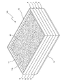
- FIG. 4 is a longitudinal cross-sectional view seen from line IV-IV of FIG. 3; It is a perspective view of the packing tray laminated body by which multiple packing trays for display panels of 1st Embodiment were laminated
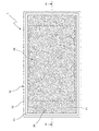
- FIG. 1 is a perspective view of a display panel packaging tray 1 according to a first embodiment of the present invention.
- the display panel packaging tray 1 of the first embodiment has a rectangular shape in which a housing recess 10 a is formed by a rectangular plate-shaped bottom 11 and a frame 12 surrounding the outer peripheral edge of the bottom 11.
- a tray body 10 a first cushioning material 20 provided on the top surface of the bottom 11 of the tray body 10, and a second cushioning material 30 (shown in FIG. 3) provided on the bottom surface of the bottom 11 of the tray body 10. Is equipped.
- the tray main body 10 is a resin molded product made of reinforced plastic or the like. Moreover, the 1st shock absorbing material 20 and the 2nd shock absorbing material 30 use the protection sheet which consists of a low resilience material as an example of a shock absorbing material.
- FIG. 2 is a top view and a side view of the display panel packaging tray 1 of the first embodiment.
- 2 (a) is a top view
- FIG. 2 (b) is a side view of the long side of the display panel packing tray 1 as viewed from the side
- FIG. 2 (c) is the display panel packing tray 1. It is the side view which looked at the short side side of from the side.
- FIG. 3 is a bottom view of the display panel packaging tray 1 of the first embodiment.
- FIG. 4 is a longitudinal sectional view seen from the line IV-IV in FIG.
- FIGS. 2 to 4 show a state in which the display panel packing tray 1 accommodates the open cell panel 40 as the packing object.
- the open cell panel 40 refers to a liquid crystal panel as an example of a display panel, COF (chip on film: chip on film) as an example of peripheral components, printed circuit board (PCB), etc. Is attached.
- the open cell panel 40 is accommodated in the accommodation recess 10 a of the tray main body 10 such that the front surface or the back surface (the front surface or the back surface of the display panel) faces the top surface of the bottom 11.
- the planar shape of the first cushioning material 20 provided on the upper surface of the bottom portion 11 is set larger than the planar shape of the open cell panel 40 (the planar shape including peripheral components of the display panel) There is.
- the entire surface of the side (lower side) opposite to the upper surface of the bottom 11 in the open cell panel 40 is supported by the first shock absorbing material 20.
- the lower surface of the bottom 11 of the tray main body 10 is provided with ribs 13 (projections) projecting downward along the outer peripheral edge (each side of the bottom 11).
- the second cushioning material 30 is provided, for example, in the entire area surrounded by the ribs 13.
- the dashed-dotted line in FIG. 3 has shown the external shape of the open cell panel 40 accommodated in the accommodation recessed part 10a. That is, the planar shape of the second cushioning material 30 is also set larger than the planar shape of the open cell panel 40 as in the case of the first cushioning material 20.
- the second buffer material 30 of the other display panel packaging tray 1 opens the display panel packaging tray 1.
- the entire surface of the second shock absorbing material 30 (upper side) of the cell panel 40 is supported.
- the display panel packaging tray 1 can be stacked in a state where the open cell panel 40 is accommodated in the accommodation recess 10 a.
- the thickness of the liquid crystal panel of the open cell panel 40 is about 1.8 mm
- the thicknesses of the first buffer 20 and the second buffer 30 are each about 3 mm
- the height of the frame 12 The distance from the upper surface of the bottom 11 to the upper end of the frame 12 is about 6 mm.
- FIG. 5 is a perspective view of a packaging tray stack 100 in which a plurality of display panel packaging trays 1 according to the first embodiment are stacked.
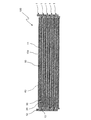
- FIG. 6 is a longitudinal sectional view of the packing tray laminate 100 of the first embodiment.
- the number of display panel packing trays 1 to be stacked is not limited to five, and 20 to 30 in actual transportation.
- the display panel packing trays 1 are stacked to form a packing tray laminate 100.
- FIG. 6 among the plurality of display panel packaging trays 1 constituting the packaging tray stack 100, display of one or more (four in the example of FIG. 6) excluding the uppermost display panel packaging tray 1 An open cell panel 40 is accommodated in each of the panel packaging trays 1. Then, in the packing tray laminate 100, the lower surface of each open cell panel 40 accommodated is supported by the first buffer material 20 of the display panel packing tray 1 in which the open cell panel 40 is accommodated. , The second buffer material of the display panel packing tray 1 (display panel packing tray 1 on the upper level) stacked on the display panel packing tray 1, the upper surface of which is housed in the open cell panel 40 Supported by 30.
- each open cell panel 40 received is the first buffer material 20 of the display panel packing tray 1 for housing the open cell panel 40, and the display panel packing tray one step higher It is clamped by the 1st 2nd shock absorbing material 30.
- each of the open cell panels 40 is formed of the first shock absorbing material 20 and the second shock absorbing material 30 in a state where the plurality of display panel packaging trays 1 accommodating the open cell panels 40 are stacked. It is pinched. That is, each open cell panel 40 is held on the panel surface by two cushioning materials. As a result, even if a large impact is received when stacking and transporting the plurality of open cell panels 40, the load is distributed to the entire panel surface of each open cell panel 40, so that it is possible to prevent the panel chipping.
- the rib 13 provided on the display panel packaging tray 1 is one step below the display panel packaging tray 1. It fits inside the frame 12 of the display panel packaging tray 1. As a result, the movement of the display panel packing tray 1 in the lateral direction is restricted.
- the vertical movement of the display panel packing tray 1 can be achieved by collectively holding the plurality of display panel packing trays 1 stacked and fastening them using, for example, a binding band, or by using a connection structure described later. It can be regulated.
- the packing tray stack 100 can be transported with a simple configuration while keeping the stacked state securely.
- the following effects can be obtained.
- the rib 13 does not protrude to the side of the frame 12, the side of the outer shape of the packing tray laminate 100 is flat and easy to handle.
- the open cell panel 40 can be held on the panel surface by the two first and second buffer members 20 and 30 by absorbing unevenness due to a substrate connector or the like in the open cell panel 40, and the substrate connector of the open cell panel 40 You can relax height restrictions such as.
- the display panel packing tray 1 since it is not necessary to position the open cell panel 40 when the open cell panel 40 is accommodated in the display panel packing tray 1, the display panel packing tray 1 accommodates a plurality of different open cell panels 40 of different sizes. can do. Therefore, the display panel packaging tray 1 having the same specification can be commonly used for a plurality of types of open cell panels 40 having different sizes.
- the planar shape of each of the first shock absorbing material 20 and the second shock absorbing material 30 is larger than the planar shape of the largest open cell panel 40 among the plurality of types of open cell panels 40.
- the ribs 13 are provided along each of the four sides of the bottom portion 11 of the tray main body 10, but the ribs 13 may be provided only on any of the four sides.
- the ribs 13 may be provided not on the entire area of the side of the bottom 11 but on part of the side.
- one open cell panel 40 is accommodated in one display panel packing tray 1, but a plurality of open cell panels 40 may be accommodated in one display panel packing tray 1. .
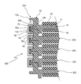
- FIG. 7 is an enlarged cross-sectional view of a main part of a packaging tray stack 400 in which a plurality of display panel packaging trays 300 according to the second embodiment of the present invention are stacked.
- the packing tray laminate 400 of the second embodiment has the same configuration as the packing tray laminate 100 of the first embodiment except for the connection structure of the display panel packing tray 300.
- the tray body 10 of the display panel packing tray 300 constituting the packing tray laminate body 400 is stacked in a stacked state.
- a connection structure for connecting the frames 12 of the plurality of display panel packaging trays 300 is provided.
- an upper flange 12a extending outward is provided at the upper end of the frame 12 of the tray main body 10, and a lower flange 12b extending outward is provided at the lower end of the frame 12 .
- the upper flange portion 12 a and the lower flange portion 12 b may be provided along the entire circumference of the frame 12 or may be provided on a part of each of the four sides of the frame 12.
- the part 12a is adjacent.
- the connecting member 50 has a U-shaped longitudinal cross section, and a base 50 a and a first bending portion 50 b which is bent from the upper end of the base 50 a and extends to the frame 12 side of the tray main body 10. , And a second bending portion 50c which is bent from the lower end of the base portion 50a and extends to the frame 12 side of the tray main body 10.
- the upper flange portion 12 a and the lower flange portion 12 b adjacent to each other are sandwiched by the first bent portion 50 b and the second bent portion 50 c of the connecting member 50.
- first bent portion 50b of the connecting member 50 is provided with an engaging claw 51 engaged with a recess 61 provided on the upper surface of the lower flange portion 12b.
- the second bent portion 50c of the connecting member 50 is provided with an engaging claw 52 engaged with a recess 62 provided on the lower surface of the upper flange portion 12a.
- the recessed portions 61 and 62 are provided in the upper flange portion 12a and the lower flange portion 12b, and the engaging claws 51 and 52 are provided in the first bent portion 50b and the second bent portion 50c, thereby forming a plurality of stacked display panels.
- the frames 12 of the packing trays 300 can be reliably connected by the connecting structure.
- the connecting structure formed by the upper flange portion 12a, the lower flange portion 12b, and the connecting member 50 Since the frames 12 of the tray body 10 are connected in a state where the plurality of tray bodies 10 are stacked, the vertical movement of the tray body 10 can be restricted without using a binding band or the like.
- the packing tray laminate of the third embodiment of the present invention has the same configuration as the packing tray laminate 400 of the second embodiment except for the connection structure, and FIG. 7 is referred to.
- the connecting member 50 magnetically attracts the upper flange portion 12a and the lower flange portion 12b while holding the upper flange portion 12a and the lower flange portion 12b adjacent to each other.
- the frame 12 in addition to the effects similar to those of the configuration of the first embodiment and the configuration of the second embodiment being obtained, the frame 12 in a state in which the plurality of tray main bodies 10 are stacked.
- a connecting member 50 that connects the two is detachably attached to the tray main body 10 by magnetic force.
- the display panel packing tray 1, 300 is A display panel packing tray 1, 300 capable of containing a display panel 40 to which peripheral parts are attached, and a display panel packing tray 1, 300 capable of being stacked in a state where the display panel 40 is contained,
- a housing recess 10 a is formed by the rectangular plate-like bottom portion 11 and the frame 12 surrounding the outer peripheral edge of the bottom portion 11, and the housing recess 10 a is formed such that the front or back surface of the display panel 40 faces the bottom 11.
- the other display panel packing tray 1, 300 having the same structure as the display panel packing tray 1, 300 is stacked on the display panel packing tray 1, 300 accommodating the display panel 40, the display The display panel 40 and the peripheral parts accommodated in the panel packing tray 1, 300 include the first buffer material 20 of the display panel packing tray 1, 300 and the other display panel packing tray 1, It is characterized in that it is held by the second shock absorbing material 30 possessed by 300.
- the bottom portion 11 of the tray main body 10 of the display panel packing trays 1, 300 is Provided on the lower surface of the bottom portion 11 of the tray main body 10 of another display panel packing tray 1, 300 having the same structure as the first buffer material 20 provided on the upper surface of the display panel packing tray 1, 300
- the display panel 40 can be held on the panel surface by the second buffer material 30.
- a plurality of types of display panels of different sizes can be accommodated in the accommodation recess 10a of the tray main body 10,
- the planar shape of each of the first shock absorber 20 and the second shock absorber 30 is larger than the planar shape including the peripheral component of the display panel with the largest size among the plurality of types of display panels.
- the tray main body 10 has projections 13 provided so as to project downward in the area along each side of the bottom 11;
- the protrusion 13 of the tray main body 10 of the other display panel packing tray 1, 300 is the above-mentioned.
- the display panel packing tray 1, 300 is fitted into the inside of the frame 12 of the tray main body 10 or the outside of the frame 12 of the display panel packing tray 1, 300 of the tray main body 10 Fit around.
- the tray main body 10 of the other display panel packaging tray 1, 300 is provided.
- the projection 13 which protrudes downward from the above restricts the lateral movement of the tray main body 10 by fitting the display panel packing tray 1, 300 into the inside of the frame 12 of the tray main body 10. .
- the protrusion 13 projecting downward of the tray body 10 of the other display panel packaging tray 1, 300 is the display panel packaging tray 1, 300. It fits so that the outer side of the frame 12 of the tray main body 10 may be enclosed.
- the display panel packing tray 1, 300 can be transported in a state where it can be transported. it can.
- the frame 12 of the display panel packing tray 1, 300 and the above A connection structure is provided for connecting with the frame 12 of another display panel packaging tray 1, 300.
- the frame 12 of the tray main body 10 is connected in a state in which the plurality of display panel packaging trays 1, 300 are stacked by the connection structure provided in the tray main body 10
- the movement of the tray main body 10 in the vertical direction can be restricted without using
- the above connection structure is An upper flange portion 12a provided at an upper end portion of the frame 12 and extending outward; A lower flange portion 12b provided at the lower end portion of the frame 12 and extending outward; A connecting member 50 for holding the upper flange portion 12a of the frame 12 of the display panel packing tray 1, 300 and the lower flange portion 12b of the frame 12 of the other display panel packing tray 1, 300 including.
- the frames 12 of the tray main body 10 are connected to each other, so that the vertical movement of the tray main body 10 can be restricted without using a binding band or the like.
- the connecting member 50 magnetically attracts the upper flange portion 12a and the lower flange portion 12b while holding the upper flange portion 12a and the lower flange portion 12b.
- the connecting members 50 connecting the frame bodies 12 with the plurality of display panel packing trays 1, 300 stacked are attracted to the upper flange portion 12a and the lower flange portion 12b by magnetic force. Are detachably attached to the tray main body 10 by this. As a result, the worker can easily attach and detach the connecting member 50, and can easily perform the packing operation and the unpacking operation of the packing tray laminate in which the plurality of display panel packing trays 1, 300 are stacked.
- the packing tray laminated body 100,400 which concerns on 1 aspect of this invention is A plurality of any one of the display panel packaging trays 1, 300 described above are stacked.
- the display panel packing tray 1, 300 is A rectangular tray main body 10 in which a housing recess 10a is formed by a plate-like bottom 11 and a frame 12 surrounding an outer peripheral edge of the bottom 11; Shock absorbers 20 and 30 provided on the upper and lower surfaces of the bottom portion 11 of the tray main body 10; The bottom portion 11 of the tray main body 10 and the cushioning members 20 and 30 are set to a shape larger than the planar shape of the open cell panel 40 which is a display panel to be packaged, The tray main body 10 provided with the shock absorbing materials 20 and 30 on the upper and lower surfaces of the bottom portion 11 can be stacked in a state in which the open cell panel 40 is sandwiched between the tray main bodies 10 It features.
- tray main body 10a accommodation recess 11: bottom 12: frame 12a: upper flange 12b: lower flange 13: rib (protrusion) 20 ... 1st shock absorbing material 30 ... 2nd shock absorbing material 40 ... open cell panel 50 ... connection member 100, 400 ... packing tray laminate
Landscapes
- Engineering & Computer Science (AREA)
- Mechanical Engineering (AREA)
- Packaging Frangible Articles (AREA)
- Buffer Packaging (AREA)
Abstract
表示パネル用梱包トレー(1)は、表示パネル(40)を収容可能で、かつ、表示パネル(40)を収容した状態で積み重ね可能であり、表示パネル(40)を収容するトレー本体10と、トレー本体10の底部(11)の上面に設けられた第1の緩衝材(20)と、トレー本体10の底部(11)の下面に設けられた第2の緩衝材(30)とを備える。表示パネル(40)を収容した表示パネル用梱包トレー(1)上に、上記表示パネル用梱包トレー(1)と同一構造を有する他の表示パネル用梱包トレー(1)を積み重ねたとき、上記表示パネル用梱包トレー(1)に収容された表示パネル(40)および周辺部品が、上記表示パネル用梱包トレー(1)の第1の緩衝材(20)と上記他の表示パネル用梱包トレー(1)が有する第2の緩衝材(30)とによって挟持される。これにより、大きな衝撃を受けてもパネル欠けを防止できる表示パネル用梱包トレーを提供する。
Description
この発明は、表示パネル用梱包トレーおよび梱包トレー積層体に関し、詳しくは、オープンセルパネルなどの表示パネルを梱包する表示パネル用梱包トレーおよびその表示パネル用梱包トレーが積層された梱包トレー積層体に関する。
従来、表示パネルなどのパネル状製品を積み重ねて搬送するときに、パネル状製品のコーナーにコーナー部材を当てて、複数のパネル状製品を所定の間隔をあけて積み重ねる方法がある(例えば、特開2012-25473号公報(特許文献1)参照)。
このような複数のパネル状製品を積み重ねる方法を用いて、表示パネルを積層して運搬する場合、表示パネルをコーナー部材により保持する面積が小さいため、運搬中に大きな衝撃を受けると、表示パネル(特にそのコーナー部分)にパネル欠けが発生するという問題がある。
そこで、この発明の課題は、複数の表示パネルを積層して運搬するための表示パネル用梱包トレーにおいて、表示パネルをパネル面で保持することによって、大きな衝撃を受けてもパネル欠けを防止できる表示パネル用梱包トレーおよび梱包トレー積層体を提供することにある。
この発明の一態様に係る表示パネル用梱包トレーは、
周辺部品が取り付けられた表示パネルを収容可能な表示パネル用梱包トレーであり、上記表示パネルを収容した状態で積み重ねることができる表示パネル用梱包トレーであって、
矩形板状の底部とその底部の外周縁を囲う枠体とによって収容凹部が形成されており、上記表示パネルの表面または裏面が上記底部に対向するように上記収容凹部に上記表示パネルを収容するトレー本体と、
上記トレー本体の上記底部の上面に設けられた第1の緩衝材と、
上記トレー本体の上記底部の下面に設けられた第2の緩衝材と
を備え、
上記表示パネルを収容した上記表示パネル用梱包トレー上に、上記表示パネル用梱包トレーと同一構造を有する他の表示パネル用梱包トレーを積み重ねたとき、上記表示パネル用梱包トレーに収容された上記表示パネルおよび上記周辺部品が、上記表示パネル用梱包トレーの上記第1の緩衝材と、上記他の表示パネル用梱包トレーが有する第2の緩衝材とによって挟持されることを特徴とする。
周辺部品が取り付けられた表示パネルを収容可能な表示パネル用梱包トレーであり、上記表示パネルを収容した状態で積み重ねることができる表示パネル用梱包トレーであって、
矩形板状の底部とその底部の外周縁を囲う枠体とによって収容凹部が形成されており、上記表示パネルの表面または裏面が上記底部に対向するように上記収容凹部に上記表示パネルを収容するトレー本体と、
上記トレー本体の上記底部の上面に設けられた第1の緩衝材と、
上記トレー本体の上記底部の下面に設けられた第2の緩衝材と
を備え、
上記表示パネルを収容した上記表示パネル用梱包トレー上に、上記表示パネル用梱包トレーと同一構造を有する他の表示パネル用梱包トレーを積み重ねたとき、上記表示パネル用梱包トレーに収容された上記表示パネルおよび上記周辺部品が、上記表示パネル用梱包トレーの上記第1の緩衝材と、上記他の表示パネル用梱包トレーが有する第2の緩衝材とによって挟持されることを特徴とする。
この発明によれば、表示パネルを複数積層して運搬するための表示パネル用梱包トレーにおいて、積み重ねられた複数の表示パネル用梱包トレーの下段側の第1の緩衝材と上段側の第2の緩衝材によって表示パネルを挟んでパネル面で保持することにより、大きな衝撃を受けてもパネル欠けを防止できる表示パネル用梱包トレーおよび梱包トレー積層体を実現することができる。
以下、この発明の表示パネル用梱包トレーおよび梱包トレー積層体を図示の実施の形態により詳細に説明する。複数の図面を通じて、同一の構成要素には同一の符号を付している。
〔第1実施形態〕
図1は、この発明の第1実施形態の表示パネル用梱包トレー1の斜視図である。
図1は、この発明の第1実施形態の表示パネル用梱包トレー1の斜視図である。
この第1実施形態の表示パネル用梱包トレー1は、図1に示すように、矩形板状の底部11と底部11の外周縁を囲う枠体12とによって収容凹部10aが形成された矩形状のトレー本体10と、トレー本体10の底部11の上面に設けられた第1の緩衝材20と、トレー本体10の底部11の下面に設けられた第2の緩衝材30(図3に示す)とを備えている。
トレー本体10は、強化プラスチックなどからなる樹脂成形品である。また、第1の緩衝材20および第2の緩衝材30は、緩衝材の一例として、低反発素材からなる保護シートを用いている。
図2は、第1実施形態の表示パネル用梱包トレー1の上面図および側面図である。図2(a)は上面図であり、図2(b)は表示パネル用梱包トレー1の長辺側を側方から見た側面図であり、図2(c)は表示パネル用梱包トレー1の短辺側を側方から見た側面図である。図3は、第1実施形態の表示パネル用梱包トレー1の下面図である。図4は、図3のIV-IV線から見た縦断面図である。
図2~図4は、表示パネル用梱包トレー1が梱包対象物であるオープンセルパネル40を収容した状態を示している。ここで、オープンセルパネル40とは、表示パネルの一例としての液晶パネルに、周辺部品の一例としてのCOF(Chip On Film:チップ・オン・フィルム)やPCB(Printed Circuit Board:プリント回路基板)などが取り付けられたものである。
トレー本体10の収容凹部10aには、オープンセルパネル40が、その表面または裏面(表示パネルの表面または裏面)が底部11の上面に対向するように収容される。図2に示すように、底部11の上面に設けられた第1の緩衝材20の平面形状は、オープンセルパネル40の平面形状(表示パネルの周辺部品を含む平面形状)よりも大きく設定されている。これにより、オープンセルパネル40における底部11の上面に対向する側(下側)の全面が第1の緩衝材20によって支持される。
図3に示すように、トレー本体10の底部11の下面には、その外周縁(底部11の各辺)に沿って下方に向けて突出するリブ13(突起部)が設けられている。底部11の下面において、第2の緩衝材30は、例えばリブ13に囲まれた全領域に設けられている。図3における一点鎖線は、収容凹部10aに収容されたオープンセルパネル40の外形を示している。すなわち、第2の緩衝材30の平面形状も、第1の緩衝材20と同様に、オープンセルパネル40の平面形状よりも大きく設定されている。これにより、オープンセルパネル40を収容した表示パネル用梱包トレー1に他の表示パネル用梱包トレー1が積み重ねられたときに、他の表示パネル用梱包トレー1の第2の緩衝材30によって、オープンセルパネル40の当該第2の緩衝材30側(上側)の全面が支持される。
図4に示すように、収容凹部10aにオープンセルパネル40が収容された状態で、オープンセルパネル40の上側の面は、枠体12の上端部よりも低い位置にある。従って、表示パネル用梱包トレー1は、オープンセルパネル40を収容凹部10aに収容した状態で積み重ねることができる。例えば、オープンセルパネル40の液晶パネルの厚さは約1.8mmであり、第1の緩衝材20および第2の緩衝材30の厚さはそれぞれ約3mmであり、枠体12の高さ(底部11の上面から枠体12の上端部までの距離)は約6mmである。
図5は、第1実施形態の表示パネル用梱包トレー1が複数積層された梱包トレー積層体100の斜視図である。図6は、第1実施形態の梱包トレー積層体100の縦断面図である。なお、図5および図6では、5つの表示パネル用梱包トレー1が積層されているが、積層される表示パネル用梱包トレー1の数は5つに限られず、実際の搬送時には20~30個の表示パネル用梱包トレー1が積層されて梱包トレー積層体100が構成される。
図6に示すように、梱包トレー積層体100を構成する複数の表示パネル用梱包トレー1のうち、最も上側の表示パネル用梱包トレー1を除く1以上(図6の例では4つ)の表示パネル用梱包トレー1のそれぞれにオープンセルパネル40が収容されている。そして、梱包トレー積層体100において、収容された各オープンセルパネル40は、その下側の面が、当該オープンセルパネル40を収容する表示パネル用梱包トレー1の第1の緩衝材20によって支持され、その上側の面が、当該オープンセルパネル40を収容する表示パネル用梱包トレー1の上に積み重ねられた表示パネル用梱包トレー1(一段上の表示パネル用梱包トレー1)の第2の緩衝材30によって支持されている。すなわち、梱包トレー積層体100において、収容された各オープンセルパネル40は、当該オープンセルパネル40を収容する表示パネル用梱包トレー1の第1の緩衝材20と、一段上の表示パネル用梱包トレー1の第2の緩衝材30とによって挟持されている。
上記構成によれば、オープンセルパネル40が収容された複数の表示パネル用梱包トレー1が積み重ねられた状態で、各オープンセルパネル40が第1の緩衝材20と第2の緩衝材30とによって挟持される。つまり、各オープンセルパネル40が2つの緩衝材によってパネル面で保持される。これによって、複数のオープンセルパネル40を積層して運搬するときに大きな衝撃を受けても、各オープンセルパネル40のパネル面全体に荷重が分散されるので、パネル欠けを防止できる。
また、オープンセルパネル40が収容された複数の表示パネル用梱包トレー1が積み重ねられた状態で、表示パネル用梱包トレー1に設けられたリブ13は、当該表示パネル用梱包トレー1の一段下の表示パネル用梱包トレー1の枠体12の内側に嵌まり込む。これによって、表示パネル用梱包トレー1の横方向への移動が規制される。なお、積み重ねられた複数の表示パネル用梱包トレー1をまとめて例えば結束バンドなどを用いて締結することにより、或いは後述する連結構造を用いることにより、表示パネル用梱包トレー1の上下方向の移動を規制することができる。このように、実施形態の構成によれば、簡易な構成で、積み重ねられた状態を確実に保持したまま梱包トレー積層体100を運搬することができる。
さらに、第1実施形態の構成によれば、以下のような効果が得られる。まず、リブ13が枠体12の側方に出っ張らないので、梱包トレー積層体100の外形の側面が平坦になり扱いやすくなる。
また、梱包トレー積層体100として運搬することでオープンセルパネル40のパネル欠けを防ぐことができるので、別途梱包箱を使用する必要がない。
また、低反発素材からなる保護シートを第1の緩衝材20および第2の緩衝材30に用いることによって、オープンセルパネル40を構成する液晶パネルの厚さよりも基板コネクタなどが高くなっても、オープンセルパネル40における基板コネクタなどによる凸凹を吸収して、2つの第1,第2の緩衝材20,30によってオープンセルパネル40をパネル面で保持することができ、オープンセルパネル40の基板コネクタなどの高さの制限を緩和することができる。
また、表示パネル用梱包トレー1にオープンセルパネル40を収容する際にオープンセルパネル40を位置決めする必要がないので、表示パネル用梱包トレー1は、サイズの異なる複数種類のオープンセルパネル40を収容することができる。従って、サイズの異なる複数種類のオープンセルパネル40に対して同一仕様の表示パネル用梱包トレー1を共通に使用することができる。ここで、第1の緩衝材20および第2の緩衝材30それぞれの平面形状は、複数種類のオープンセルパネル40のうちサイズの最も大きいオープンセルパネル40の平面形状よりも大きい。
なお、第1実施形態では、トレー本体10の底部11の4つの辺のそれぞれに沿ってリブ13を設けたが、4つの辺のうちの何れかの辺にだけリブ13を設けてもよいし、底部11の辺の全域ではなく辺の一部にリブ13を設けてもよい。また、第1実施形態では、1つの表示パネル用梱包トレー1に1つのオープンセルパネル40が収容されたが、1つの表示パネル用梱包トレー1に複数のオープンセルパネル40が収容されてもよい。
〔第2実施形態〕
図7は、この発明の第2実施形態の表示パネル用梱包トレー300が複数積層された梱包トレー積層体400の要部の拡大断面図である。第2実施形態の梱包トレー積層体400は、表示パネル用梱包トレー300の連結構造を除いて第1実施形態の梱包トレー積層体100と同一の構成である。
図7は、この発明の第2実施形態の表示パネル用梱包トレー300が複数積層された梱包トレー積層体400の要部の拡大断面図である。第2実施形態の梱包トレー積層体400は、表示パネル用梱包トレー300の連結構造を除いて第1実施形態の梱包トレー積層体100と同一の構成である。
図7に示すように、第2実施形態の梱包トレー積層体400において、該梱包トレー積層体400を構成する表示パネル用梱包トレー300のトレー本体10には、積み重ねられた状態で、積み重ねられた複数の表示パネル用梱包トレー300それぞれの枠体12間を連結するための連結構造が設けられている。
詳しくは、トレー本体10の枠体12の上端部に、外側に向かって延びる上フランジ部12aが設けられ、枠体12の下端部に、外側に向かって延びる下フランジ部12bが設けられている。上フランジ部12aおよび下フランジ部12bは、枠体12の全周に渡って設けられてもよいし、枠体12の4つの辺のそれぞれの一部に設けられてもよい。
複数の表示パネル用梱包トレー300(トレー本体10)が積み重ねられた状態で、隣接する2つのトレー本体10のうちの上側のトレー本体10の下フランジ部12bと下側のトレー本体10の上フランジ部12aとが隣接している。
この隣接する上フランジ部12aと下フランジ部12bとを連結部材50により挟み込むことにより、隣接する2つのトレー本体10それぞれの枠体12間が連結されている。
本実施形態において、連結部材50は、縦断面がコの字形状をしており、基部50aと、基部50aの上端から屈曲してトレー本体10の枠体12側に延びる第1屈曲部50bと、基部50aの下端から屈曲してトレー本体10の枠体12側に延びる第2屈曲部50cとを有する。
連結部材50の第1屈曲部50bと第2屈曲部50cとによって、隣接する上フランジ部12aと下フランジ部12bとが挟持される。
また、連結部材50の第1屈曲部50bには、下フランジ部12bの上面に設けた凹部61に係合する係合爪51が設けられている。連結部材50の第2屈曲部50cには、上フランジ部12aの下面に設けた凹部62に係合する係合爪52が設けられている。上フランジ部12aおよび下フランジ部12bに凹部61,62が設けられ、第1屈曲部50bおよび第2屈曲部50cに係合爪51,52が設けられることにより、積み重ねられた複数の表示パネル用梱包トレー300それぞれの枠体12間を連結構造により確実に連結することができる。
第2実施形態の構成によれば、第1実施形態の構成と同様の効果が得られることに加えて、上フランジ部12a、下フランジ部12b、および連結部材50により形成される連結構造により、複数のトレー本体10が積み重ねられた状態でトレー本体10の枠体12間が連結されるので、結束バンドなどを用いることなく、トレー本体10の上下方向への移動を規制することができる。
〔第3実施形態〕
この発明の第3実施形態の梱包トレー積層体は、連結構造を除いて第2実施形態の梱包トレー積層体400と同一の構成であり、図7を援用する。
この発明の第3実施形態の梱包トレー積層体は、連結構造を除いて第2実施形態の梱包トレー積層体400と同一の構成であり、図7を援用する。
第3実施形態の梱包トレー積層体では、連結部材50に永久磁石(図示せず)が埋め込まれており、トレー本体10の枠体12の上フランジ部12aおよび下フランジ部12bに鉄片(図示せず)が埋め込まれている。
これにより、連結部材50は、隣接する上フランジ部12aと下フランジ部12bとを挟持した状態で、上フランジ部12aおよび下フランジ部12bに磁力で吸着する。
第3実施形態の構成によれば、第1実施形態の構成および第2実施形態の構成と同様の効果が得られることに加えて、複数のトレー本体10が積み重ねられた状態で、枠体12間を連結する連結部材50が、磁力によりトレー本体10に着脱可能に取り付けられる。これにより、作業者は、連結構造を有する梱包トレー積層体の梱包作業および開梱作業を容易に行えるようになる。
この発明の具体的な実施の形態について説明したが、この発明は上記第1~第3実施形態に限定されるものではなく、この発明の範囲内で種々変更して実施することができる。例えば、上記第1~第3実施形態で記載した内容を適宜組み合わせたものを、この発明の一実施形態としてもよい。
この発明および実施形態をまとめると、次のようになる。
この発明の一態様に係る表示パネル用梱包トレー1,300は、
周辺部品が取り付けられた表示パネル40を収容可能な表示パネル用梱包トレー1,300であり、上記表示パネル40を収容した状態で積み重ね可能な表示パネル用梱包トレー1,300であって、
矩形板状の底部11とその底部11の外周縁を囲う枠体12とによって収容凹部10aが形成されており、上記表示パネル40の表面または裏面が上記底部11に対向するように上記収容凹部10aに上記表示パネル40を収容するトレー本体10と、
上記トレー本体10の上記底部11の上面に設けられた第1の緩衝材20と、
上記トレー本体10の上記底部11の下面に設けられた第2の緩衝材30と
を備え、
上記表示パネル40を収容した上記表示パネル用梱包トレー1,300上に、上記表示パネル用梱包トレー1,300と同一構造を有する他の表示パネル用梱包トレー1,300を積み重ねたとき、上記表示パネル用梱包トレー1,300に収容された上記表示パネル40および上記周辺部品が、上記表示パネル用梱包トレー1,300の上記第1の緩衝材20と、上記他の表示パネル用梱包トレー1,300が有する第2の緩衝材30とによって挟持されることを特徴とする。
周辺部品が取り付けられた表示パネル40を収容可能な表示パネル用梱包トレー1,300であり、上記表示パネル40を収容した状態で積み重ね可能な表示パネル用梱包トレー1,300であって、
矩形板状の底部11とその底部11の外周縁を囲う枠体12とによって収容凹部10aが形成されており、上記表示パネル40の表面または裏面が上記底部11に対向するように上記収容凹部10aに上記表示パネル40を収容するトレー本体10と、
上記トレー本体10の上記底部11の上面に設けられた第1の緩衝材20と、
上記トレー本体10の上記底部11の下面に設けられた第2の緩衝材30と
を備え、
上記表示パネル40を収容した上記表示パネル用梱包トレー1,300上に、上記表示パネル用梱包トレー1,300と同一構造を有する他の表示パネル用梱包トレー1,300を積み重ねたとき、上記表示パネル用梱包トレー1,300に収容された上記表示パネル40および上記周辺部品が、上記表示パネル用梱包トレー1,300の上記第1の緩衝材20と、上記他の表示パネル用梱包トレー1,300が有する第2の緩衝材30とによって挟持されることを特徴とする。
上記構成によれば、表示パネル40をトレー本体10間に挟んだ状態で複数の表示パネル用梱包トレー1,300を積み重ねることにより、上記表示パネル用梱包トレー1,300のトレー本体10の底部11の上面に設けられた第1の緩衝材20と、上記表示パネル用梱包トレー1,300と同一構造を有する他の表示パネル用梱包トレー1,300のトレー本体10の底部11の下面に設けられた第2の緩衝材30とによって、表示パネル40全体および周辺部品を覆うように挟持することにより、表示パネル40をパネル面で保持することが可能になる。これによって、表示パネル40を積層して運搬するときに、大きな衝撃を受けても、表示パネル40のパネル面全体に荷重が分散されるので、パネル欠けを防止できる。
また、一実施形態の表示パネル用梱包トレー1,300では、
上記トレー本体10の上記収容凹部10aに、サイズの異なる複数種類の上記表示パネルを収容可能であり、
上記第1の緩衝材20および上記第2の緩衝材30それぞれの平面形状は、上記複数種類の表示パネルのうちサイズの最も大きい表示パネルの上記周辺部品を含む平面形状よりも大きい。
上記トレー本体10の上記収容凹部10aに、サイズの異なる複数種類の上記表示パネルを収容可能であり、
上記第1の緩衝材20および上記第2の緩衝材30それぞれの平面形状は、上記複数種類の表示パネルのうちサイズの最も大きい表示パネルの上記周辺部品を含む平面形状よりも大きい。
また、一実施形態の表示パネル用梱包トレー1,300では、
上記トレー本体10は、上記底部11の各辺に沿った領域に下方に向かって突出するように設けられた突起部13を有し、
上記表示パネル用梱包トレー1,300上に上記他の表示パネル用梱包トレー1,300を積み重ねたとき、上記他の表示パネル用梱包トレー1,300が有するトレー本体10の突起部13は、上記表示パネル用梱包トレー1,300の上記トレー本体10の上記枠体12の内側に嵌まり込むか、または、上記表示パネル用梱包トレー1,300の上記トレー本体10の上記枠体12の外側を囲むように嵌まる。
上記トレー本体10は、上記底部11の各辺に沿った領域に下方に向かって突出するように設けられた突起部13を有し、
上記表示パネル用梱包トレー1,300上に上記他の表示パネル用梱包トレー1,300を積み重ねたとき、上記他の表示パネル用梱包トレー1,300が有するトレー本体10の突起部13は、上記表示パネル用梱包トレー1,300の上記トレー本体10の上記枠体12の内側に嵌まり込むか、または、上記表示パネル用梱包トレー1,300の上記トレー本体10の上記枠体12の外側を囲むように嵌まる。
上記実施形態によれば、上記表示パネル用梱包トレー1,300上に上記他の表示パネル用梱包トレー1,300を積み重ねたとき、上記他の表示パネル用梱包トレー1,300が有するトレー本体10の下方に向かって突出する突起部13は、上記表示パネル用梱包トレー1,300のトレー本体10の枠体12の内側に嵌まり込むことによって、トレー本体10の横方向への移動を規制する。または、複数のトレー本体10が積み重ねられた状態で、上記他の表示パネル用梱包トレー1,300のトレー本体10の下方に向かって突出する突起部13は、上記表示パネル用梱包トレー1,300のトレー本体10の枠体12の外側を囲むように嵌まる。
これによって、トレー本体10間を連結する構造や結束バンドなどを用いて上下方向の移動を規制するだけで、表示パネル用梱包トレー1,300が複数積層された積層体を運搬可能な状態に梱包できる。
また、一実施形態の表示パネル用梱包トレー1,300では、
上記トレー本体10には、上記表示パネル用梱包トレー1,300上に上記他の表示パネル用梱包トレー1,300を積み重ねたとき、上記表示パネル用梱包トレー1,300の上記枠体12と上記他の表示パネル用梱包トレー1,300が有する枠体12とを連結するための連結構造が設けられている。
上記トレー本体10には、上記表示パネル用梱包トレー1,300上に上記他の表示パネル用梱包トレー1,300を積み重ねたとき、上記表示パネル用梱包トレー1,300の上記枠体12と上記他の表示パネル用梱包トレー1,300が有する枠体12とを連結するための連結構造が設けられている。
上記実施形態によれば、トレー本体10に設けられた連結構造により、複数の表示パネル用梱包トレー1,300が積み重ねられた状態でトレー本体10の枠体12間を連結するので、結束バンドなどを用いることなく、トレー本体10の上下方向への移動を規制することができる。
また、一実施形態の表示パネル用梱包トレー1,300では、
上記連結構造は、
上記枠体12の上端部に設けられ、外側に向かって延びる上フランジ部12aと、
上記枠体12の下端部に設けられ、外側に向かって延びる下フランジ部12bと、
上記表示パネル用梱包トレー1,300の上記枠体12の上記上フランジ部12aと上記他の表示パネル用梱包トレー1,300が有する枠体12の下フランジ部12bとを挟持する連結部材50と
を含む。
上記連結構造は、
上記枠体12の上端部に設けられ、外側に向かって延びる上フランジ部12aと、
上記枠体12の下端部に設けられ、外側に向かって延びる下フランジ部12bと、
上記表示パネル用梱包トレー1,300の上記枠体12の上記上フランジ部12aと上記他の表示パネル用梱包トレー1,300が有する枠体12の下フランジ部12bとを挟持する連結部材50と
を含む。
上記実施形態によれば、複数の表示パネル用梱包トレー1,300が積み重ねられた状態で、連結部材50によって、上記表示パネル用梱包トレー1,300の枠体12の上フランジ部12aと上記他の表示パネル用梱包トレー1,300が有する枠体12の下フランジ部12bとを挟持する。これにより、トレー本体10の枠体12間が連結されるので、結束バンドなどを用いることなく、トレー本体10の上下方向への移動を規制することができる。
また、一実施形態の表示パネル用梱包トレー1,300では、
上記連結部材50は、上記上フランジ部12aと上記下フランジ部12bとを挟持した状態で上記上フランジ部12aおよび上記下フランジ部12bに磁力で吸着する。
上記連結部材50は、上記上フランジ部12aと上記下フランジ部12bとを挟持した状態で上記上フランジ部12aおよび上記下フランジ部12bに磁力で吸着する。
上記実施形態によれば、複数の表示パネル用梱包トレー1,300が積み重ねられた状態で枠体12間を連結する連結部材50が、上フランジ部12aおよび下フランジ部12bに磁力で吸着することによりトレー本体10に着脱可能に取り付けられる。これにより、作業者は、連結部材50の着脱が容易にでき、複数の表示パネル用梱包トレー1,300が積み重ねられた梱包トレー積層体の梱包作業および開梱作業を容易に行えるようになる。
また、この発明の一態様に係る梱包トレー積層体100,400は、
上記のいずれか1つの表示パネル用梱包トレー1,300を複数積層したことを特徴とする。
上記のいずれか1つの表示パネル用梱包トレー1,300を複数積層したことを特徴とする。
上記構成によれば、複数の表示パネル40を積層して運搬する梱包トレー積層体100,400において、表示パネル40をパネル面で保持することによって、大きな衝撃を受けてもパネル欠けを防止することができる。
また、この発明の一態様に係る表示パネル用梱包トレー1,300は、
板状の底部11とその底部11の外周縁を囲う枠体12によって収容凹部10aが形成された矩形状のトレー本体10と、
上記トレー本体10の上記底部11の上面および下面に設けられた緩衝材20,30と
を備え、
上記トレー本体10の上記底部11および上記緩衝材20,30は、梱包する表示パネルであるオープンセルパネル40の平面形状よりも大きい形状に設定されており、
上記緩衝材20,30が上記底部11の上面および下面に設けられた上記トレー本体10は、上記オープンセルパネル40を上記トレー本体10間に挟んだ状態で積み重ね可能な構成をしていることを特徴とする。
板状の底部11とその底部11の外周縁を囲う枠体12によって収容凹部10aが形成された矩形状のトレー本体10と、
上記トレー本体10の上記底部11の上面および下面に設けられた緩衝材20,30と
を備え、
上記トレー本体10の上記底部11および上記緩衝材20,30は、梱包する表示パネルであるオープンセルパネル40の平面形状よりも大きい形状に設定されており、
上記緩衝材20,30が上記底部11の上面および下面に設けられた上記トレー本体10は、上記オープンセルパネル40を上記トレー本体10間に挟んだ状態で積み重ね可能な構成をしていることを特徴とする。
1,300…表示パネル用梱包トレー
10…トレー本体
10a…収容凹部
11…底部
12…枠体
12a…上フランジ部
12b…下フランジ部
13…リブ(突起部)
20…第1の緩衝材
30…第2の緩衝材
40…オープンセルパネル
50…連結部材
100,400…梱包トレー積層体
10…トレー本体
10a…収容凹部
11…底部
12…枠体
12a…上フランジ部
12b…下フランジ部
13…リブ(突起部)
20…第1の緩衝材
30…第2の緩衝材
40…オープンセルパネル
50…連結部材
100,400…梱包トレー積層体
Claims (7)
- 周辺部品が取り付けられた表示パネルを収容可能な表示パネル用梱包トレーであり、上記表示パネルを収容した状態で積み重ねることができる表示パネル用梱包トレーであって、
矩形板状の底部とその底部の外周縁を囲う枠体とによって収容凹部が形成されており、上記表示パネルの表面または裏面が上記底部に対向するように上記収容凹部に上記表示パネルを収容するトレー本体と、
上記トレー本体の上記底部の上面に設けられた第1の緩衝材と、
上記トレー本体の上記底部の下面に設けられた第2の緩衝材と
を備え、
上記表示パネルを収容した上記表示パネル用梱包トレー上に、上記表示パネル用梱包トレーと同一構造を有する他の表示パネル用梱包トレーを積み重ねたとき、上記表示パネル用梱包トレーに収容された上記表示パネルおよび上記周辺部品が、上記表示パネル用梱包トレーの上記第1の緩衝材と、上記他の表示パネル用梱包トレーが有する第2の緩衝材とによって挟持されることを特徴とする表示パネル用梱包トレー。 - 請求項1に記載の表示パネル用梱包トレーにおいて、
上記トレー本体の上記収容凹部に、サイズの異なる複数種類の上記表示パネルを収容可能であり、
上記第1の緩衝材および上記第2の緩衝材それぞれの平面形状は、上記複数種類の表示パネルのうちサイズの最も大きい表示パネルの上記周辺部品を含む平面形状よりも大きいことを特徴とする表示パネル用梱包トレー。 - 請求項1または2に記載の表示パネル用梱包トレーにおいて、
上記トレー本体は、上記底部の各辺に沿った領域に下方に向かって突出するように設けられた突起部を有し、
上記表示パネル用梱包トレー上に上記他の表示パネル用梱包トレーを積み重ねたとき、上記他の表示パネル用梱包トレーが有するトレー本体の突起部は、上記表示パネル用梱包トレーの上記トレー本体の上記枠体の内側に嵌まり込むか、または、上記表示パネル用梱包トレーの上記トレー本体の上記枠体の外側を囲むように嵌まることを特徴とする表示パネル用梱包トレー。 - 請求項1から3までのいずれか1つに記載の表示パネル用梱包トレーにおいて、
上記トレー本体には、上記表示パネル用梱包トレー上に上記他の表示パネル用梱包トレーを積み重ねたとき、上記表示パネル用梱包トレーの上記枠体と上記他の表示パネル用梱包トレーが有する枠体とを連結するための連結構造が設けられていることを特徴とする表示パネル用梱包トレー。 - 請求項4に記載の表示パネル用梱包トレーにおいて、
上記連結構造は、
上記枠体の上端部に設けられ、外側に向かって延びる上フランジ部と、
上記枠体の下端部に設けられ、外側に向かって延びる下フランジ部と、
上記表示パネル用梱包トレーの上記枠体の上記上フランジ部と上記他の表示パネル用梱包トレーが有する枠体の下フランジ部とを挟持する連結部材と
を含むことを特徴とする表示パネル用梱包トレー。 - 請求項5に記載の表示パネル用梱包トレーにおいて、
上記連結部材は、上記上フランジ部と上記下フランジ部とを挟持した状態で上記上フランジ部および上記下フランジ部に磁力で吸着することを特徴とする表示パネル用梱包トレー。 - 請求項1から6までのいずれか1つに記載の表示パネル用梱包トレーを複数積層したことを特徴とする梱包トレー積層体。
Priority Applications (1)
| Application Number | Priority Date | Filing Date | Title |
|---|---|---|---|
| PCT/JP2017/038491 WO2019082298A1 (ja) | 2017-10-25 | 2017-10-25 | 表示パネル用梱包トレーおよび梱包トレー積層体 |
Applications Claiming Priority (1)
| Application Number | Priority Date | Filing Date | Title |
|---|---|---|---|
| PCT/JP2017/038491 WO2019082298A1 (ja) | 2017-10-25 | 2017-10-25 | 表示パネル用梱包トレーおよび梱包トレー積層体 |
Publications (1)
| Publication Number | Publication Date |
|---|---|
| WO2019082298A1 true WO2019082298A1 (ja) | 2019-05-02 |
Family
ID=66246883
Family Applications (1)
| Application Number | Title | Priority Date | Filing Date |
|---|---|---|---|
| PCT/JP2017/038491 Ceased WO2019082298A1 (ja) | 2017-10-25 | 2017-10-25 | 表示パネル用梱包トレーおよび梱包トレー積層体 |
Country Status (1)
| Country | Link |
|---|---|
| WO (1) | WO2019082298A1 (ja) |
Cited By (3)
| Publication number | Priority date | Publication date | Assignee | Title |
|---|---|---|---|---|
| CN110451064A (zh) * | 2019-08-21 | 2019-11-15 | 长虹美菱股份有限公司 | 一种曲面玻璃包装运输装置 |
| CN112249477A (zh) * | 2020-11-15 | 2021-01-22 | 苏州工业园区凯达电子材料有限公司 | 耐擦洗性防静电吸塑托盘 |
| CN112896718A (zh) * | 2021-01-15 | 2021-06-04 | 业成科技(成都)有限公司 | 包装结构及其包装方法 |
Citations (9)
| Publication number | Priority date | Publication date | Assignee | Title |
|---|---|---|---|---|
| JP2004067249A (ja) * | 2002-07-22 | 2004-03-04 | Asahi Glass Co Ltd | 大型ガラス板の搬送方法及び搬送用トレイ |
| JP2006168749A (ja) * | 2004-12-14 | 2006-06-29 | Kyokuhei Glass Kako Kk | ガラス搬送用枠体 |
| JP2006168748A (ja) * | 2004-12-14 | 2006-06-29 | Kyokuhei Glass Kako Kk | ガラス搬送用枠体 |
| JP2009298421A (ja) * | 2008-06-11 | 2009-12-24 | Sekisui Plastics Co Ltd | ガラス基板搬送用トレイとガラス基板梱包体 |
| JP2010100308A (ja) * | 2008-10-23 | 2010-05-06 | Sekisui Plastics Co Ltd | 突起を有する平板部材の搬送容器とそれを用いた平板部材搬送体 |
| JP2011063269A (ja) * | 2009-09-15 | 2011-03-31 | Fujitsu Semiconductor Ltd | 半導体素子用収容器 |
| JP2012062081A (ja) * | 2010-09-15 | 2012-03-29 | Sekisui Plastics Co Ltd | 板状体の搬送用容器 |
| JP2016000628A (ja) * | 2015-07-07 | 2016-01-07 | 大日本印刷株式会社 | 基板保持用枠体と基板の梱包体 |
| JP2016020242A (ja) * | 2015-11-06 | 2016-02-04 | 大日本印刷株式会社 | 基板保持用枠体と基板の梱包体 |
-
2017
- 2017-10-25 WO PCT/JP2017/038491 patent/WO2019082298A1/ja not_active Ceased
Patent Citations (9)
| Publication number | Priority date | Publication date | Assignee | Title |
|---|---|---|---|---|
| JP2004067249A (ja) * | 2002-07-22 | 2004-03-04 | Asahi Glass Co Ltd | 大型ガラス板の搬送方法及び搬送用トレイ |
| JP2006168749A (ja) * | 2004-12-14 | 2006-06-29 | Kyokuhei Glass Kako Kk | ガラス搬送用枠体 |
| JP2006168748A (ja) * | 2004-12-14 | 2006-06-29 | Kyokuhei Glass Kako Kk | ガラス搬送用枠体 |
| JP2009298421A (ja) * | 2008-06-11 | 2009-12-24 | Sekisui Plastics Co Ltd | ガラス基板搬送用トレイとガラス基板梱包体 |
| JP2010100308A (ja) * | 2008-10-23 | 2010-05-06 | Sekisui Plastics Co Ltd | 突起を有する平板部材の搬送容器とそれを用いた平板部材搬送体 |
| JP2011063269A (ja) * | 2009-09-15 | 2011-03-31 | Fujitsu Semiconductor Ltd | 半導体素子用収容器 |
| JP2012062081A (ja) * | 2010-09-15 | 2012-03-29 | Sekisui Plastics Co Ltd | 板状体の搬送用容器 |
| JP2016000628A (ja) * | 2015-07-07 | 2016-01-07 | 大日本印刷株式会社 | 基板保持用枠体と基板の梱包体 |
| JP2016020242A (ja) * | 2015-11-06 | 2016-02-04 | 大日本印刷株式会社 | 基板保持用枠体と基板の梱包体 |
Cited By (4)
| Publication number | Priority date | Publication date | Assignee | Title |
|---|---|---|---|---|
| CN110451064A (zh) * | 2019-08-21 | 2019-11-15 | 长虹美菱股份有限公司 | 一种曲面玻璃包装运输装置 |
| CN110451064B (zh) * | 2019-08-21 | 2024-03-12 | 长虹美菱股份有限公司 | 一种曲面玻璃包装运输装置 |
| CN112249477A (zh) * | 2020-11-15 | 2021-01-22 | 苏州工业园区凯达电子材料有限公司 | 耐擦洗性防静电吸塑托盘 |
| CN112896718A (zh) * | 2021-01-15 | 2021-06-04 | 业成科技(成都)有限公司 | 包装结构及其包装方法 |
Similar Documents
| Publication | Publication Date | Title |
|---|---|---|
| CN107521851B (zh) | 包装材及包装体 | |
| US8777008B2 (en) | Package cushioning structure for liquid crystal display module | |
| US9233787B2 (en) | Cushioning material | |
| KR102870026B1 (ko) | 기판 트레이 | |
| JP2006168749A (ja) | ガラス搬送用枠体 | |
| KR200490607Y1 (ko) | 패널 반송 용기 | |
| US20200130915A1 (en) | Packaging tray | |
| JP6357218B2 (ja) | 梱包材および梱包体 | |
| CN104386359A (zh) | 基板包装结构及基板包装结构组 | |
| CN214139756U (zh) | 一种包装箱 | |
| US20210039852A1 (en) | Packaging case | |
| KR101574610B1 (ko) | 포장상자용 덮개 | |
| JP2011235936A (ja) | 梱包用緩衝体及び梱包用緩衝体セット | |
| JP7263752B2 (ja) | 梱包装置 | |
| JP2015231860A (ja) | 梱包材 | |
| KR200477851Y1 (ko) | 보강 부재 및 패널 반송 용기 | |
| CN101214870B (zh) | 板形电子装置的承载装置及包装装置 | |
| TWI627110B (zh) | Package structure for packaging substrate storage container | |
| JP2007073871A (ja) | 薄形表示装置用基板の工程間搬送に使用するトレイ及びそれを使用した薄形表示装置用基板の出荷方法 | |
| CN110065728A (zh) | 一种异质复合缓冲包装箱及异质复合缓冲结构 | |
| US20210380366A1 (en) | Arrangement for securing plate-like material | |
| JP4064696B2 (ja) | 板状体の搬送用パッド | |
| CN107021297A (zh) | 构造体 | |
| JP2562130Y2 (ja) | 板状物包装体 | |
| CN109843733B (zh) | 加固纸板箱 |
Legal Events
| Date | Code | Title | Description |
|---|---|---|---|
| 121 | Ep: the epo has been informed by wipo that ep was designated in this application |
Ref document number: 17929594 Country of ref document: EP Kind code of ref document: A1 |
|
| NENP | Non-entry into the national phase |
Ref country code: DE |
|
| 122 | Ep: pct application non-entry in european phase |
Ref document number: 17929594 Country of ref document: EP Kind code of ref document: A1 |
|
| NENP | Non-entry into the national phase |
Ref country code: JP |