WO2019078200A1 - Press brake - Google Patents
Press brake Download PDFInfo
- Publication number
- WO2019078200A1 WO2019078200A1 PCT/JP2018/038472 JP2018038472W WO2019078200A1 WO 2019078200 A1 WO2019078200 A1 WO 2019078200A1 JP 2018038472 W JP2018038472 W JP 2018038472W WO 2019078200 A1 WO2019078200 A1 WO 2019078200A1
- Authority
- WO
- WIPO (PCT)
- Prior art keywords
- pedal
- pedal case
- case
- press brake
- foot
- Prior art date
Links
Images


Classifications
-
- B—PERFORMING OPERATIONS; TRANSPORTING
- B21—MECHANICAL METAL-WORKING WITHOUT ESSENTIALLY REMOVING MATERIAL; PUNCHING METAL
- B21D—WORKING OR PROCESSING OF SHEET METAL OR METAL TUBES, RODS OR PROFILES WITHOUT ESSENTIALLY REMOVING MATERIAL; PUNCHING METAL
- B21D5/00—Bending sheet metal along straight lines, e.g. to form simple curves
- B21D5/02—Bending sheet metal along straight lines, e.g. to form simple curves on press brakes without making use of clamping means
-
- B—PERFORMING OPERATIONS; TRANSPORTING
- B30—PRESSES
- B30B—PRESSES IN GENERAL
- B30B15/00—Details of, or accessories for, presses; Auxiliary measures in connection with pressing
Definitions
- the present invention relates to a press brake that performs bending on a plate-like work (sheet metal) in cooperation with an upper mold (punch mold) and a lower mold (die mold).
- step bending in which bending is sequentially performed based on the bending order of workpieces, is widely used.
- a movable foot switch device in which the pedal case can be moved in the longitudinal direction (the longitudinal direction of the press brake).
- the configuration of the movable foot switch device is as follows (see Patent Document 1 to Patent Document 5 and the like).
- a guide member extending in the lengthwise direction is provided on the lower portion of the lower table or on the front side thereof, and a slide member is provided on the guide member so as to be movable in the lengthwise direction.
- a pedal case is provided on the slide member, and a foot pedal that can be stepped on is provided in the pedal case.
- the pedal case is divided into a motor drive type that moves in the longitudinal direction with the slide member by driving of the electric motor and a manual type (human power type) that moves in the longitudinal direction with the slide member by manual operation (human power) .
- a motor drive type foot switch device in addition to the electric motor, the electric motor and the slide member are interlocked (linked) Therefore, an interlocking mechanism such as a screw mechanism or a belt mechanism is required as a component, and the structure of the foot switch device is complicated.
- the program for controlling the electric motor or the like must be corrected each time, and the operation becomes complicated.
- a manual type foot switch device having a manual type pedal case
- the electric motor etc. are not used, so the configuration of the foot switch device is simplified.
- Can be even if there is a change in the layout of the mold, etc., it is not necessary to modify the program etc. simply by changing the position of the pedal case manually (manually), and it is possible to cope flexibly.
- an object of this invention is to provide the press brake of a novel structure which can solve the problem of the above-mentioned manual type foot switch apparatus. More specifically, the present invention aims to provide a press brake capable of stably maintaining the processing accuracy of bending by bending the workpiece W in a stable posture.
- a lower table provided at the lower part of the main body frame and holding the lower mold at the upper side, and provided at the upper part of the main body frame so as to be vertically movable (movable vertically).
- the upper mold punctch mold
- the upper mold includes an upper table for holding an upper mold, and a movable foot switch device for moving up and down (lowering and raising operations) of the upper table by a stepping operation.
- a guide member provided on another member disposed on the front side of the table and extending in the longitudinal direction, a slide member movably provided on the guide member in the longitudinal direction, and the slide member
- a pedal case which is provided so as to be able to pivot downward and has a stopper portion (contact portion) capable of coming into contact with a floor surface, and which is manually moved (manually) together with the slide member in the longitudinal direction;
- a foot pedal which can be operated by stepping and a rolling element which is provided movably in the vertical direction on both sides in the longitudinal direction of the pedal case, and which rolls (rotates) along the longitudinal direction on the floor surface
- a press brake is provided having a rotating body) and an urging member urging each rolling element downward with respect to the pedal case.
- each rolling element ascends relative to the pedal case against the urging force of the urging member, and the pedal case
- the stopper portion is configured to be in contact with the floor surface.
- the pedal case is configured to be adjustable in height with respect to the guide member.
- the foot switch device has a post erected on the pedal case and gripped by an operator.
- step bend bending at a plurality of processing stations formed between the upper table and the lower table according to the configuration of the press brake of the present invention, the following is performed.
- the pedal case is moved longitudinally along with the slide member manually (manually) and positioned at a position corresponding to the first processing station (the first bending processing station).
- the work is positioned relative to the lower mold in the depth direction (the depth direction of the press brake).
- the upper table is moved up and down by stepping on the foot pedal by the operator.
- the first bending process can be performed on the work by the cooperation of the upper mold and the lower mold.
- the pedal case After performing the first bending process on the work, the pedal case is moved along with the slide member in the length direction manually (manually) based on the bending order of the work, and the subsequent processing stations (next and subsequent steps) Position at the position corresponding to the processing station) where bending is performed.
- the work is positioned in the depth direction with respect to the lower mold.
- the upper table is moved up and down by stepping on the foot pedal by the operator.
- the pedal case is configured to be swingable in the vertical direction on the slide member, and includes the stopper portion capable of contacting the floor surface.
- the rolling elements provided so as to be vertically movable on both sides in the longitudinal direction of the pedal case are biased downward with respect to the pedal case by the biasing member. Therefore, when the operator depresses the foot pedal, each rolling element ascends relative to the pedal case while resisting the biasing force of the biasing member, and the stopper portion of the pedal case is a floor surface Contact As a result, when the operator depresses the foot pedal, the pedal case can be prevented from slightly moving in the longitudinal direction with the slide member.
- the work when the operator steps on the foot pedal, the work can be bent in a stable posture without losing the balance, and the processing accuracy of the bending can be stably maintained. it can.
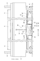
- FIG. 1 is a schematic front view of a press brake according to an embodiment of the present invention.
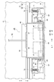
- FIG. 2 is a schematic partial side view of a press brake according to an embodiment of the present invention.
- FIG. 3 is a schematic partial enlarged front view of the press brake according to the embodiment of the present invention.
- FIG. 4 is an enlarged front view of the periphery of the foot switch device of the press brake according to the embodiment of the present invention.
- FIG. 5 is an enlarged side view of the periphery of the foot switch device of the press brake according to the embodiment of the present invention.
- 6 (a) and 6 (b) are diagrams for explaining the characterizing portion of the foot switch device of the press brake according to the embodiment of the present invention.
- FIG. 6 (a) shows the state before the lowering foot pedal or the raising foot pedal is depressed
- FIG. 6 (b) shows the state where the lowering foot pedal or the raising foot pedal is depressed. .
- the “longitudinal direction” refers to one in the horizontal direction, that is, in the longitudinal direction of the press brake, and in the embodiment of the present invention, to the lateral direction.
- the “depth direction” refers to one in the horizontal direction, that is, the depth direction of the press brake, and in the embodiment of the present invention, the front-rear direction.
- FF forward
- FR backward
- L left
- R right
- U is upward
- D is downward. Point to each.
- the press brake 1 is a plate-like work (the punch die) and the lower die (die die) 5 cooperate with each other. It is a processing machine that performs bending on a sheet metal (W).
- the press brake 1 further includes a main body frame 7.
- the main body frame 7 includes a plurality of side plates 9 that are spaced apart and opposed in the length direction (left and right direction) and a plurality of side plates 9 And only one connecting member 11 shown).
- Each side plate 9 is installed to be adjustable in height with respect to the floor surface F by a level bolt 13.
- a lower table 15 extending in the length direction (left and right direction) is provided.
- a lower mold holder 17 is provided which detachably holds a plurality of lower molds 5 spaced apart in the lengthwise direction.
- an upper table 19 extending in the length direction is provided at the upper part of the main body frame 7 so as to be vertically movable (movable in the vertical direction), and the upper table 19 is vertically opposed to the lower table 15 .
- an upper mold holder 21 for detachably holding a plurality of upper molds 3 spaced apart in the lengthwise direction is provided.
- a hydraulic cylinder 23 is provided on the upper portion of each side plate 9 as a lifting actuator for lifting and lowering the upper table 19.
- An electric motor (not shown) may be used instead of the hydraulic cylinder 23 as the lift actuator.
- a plurality of processing stations S for performing the step bending process are formed by the plurality of upper molds 3 and the plurality of lower molds 5. Further, on the back side of the lower table 15, a back gauge device 25 for positioning the work W in the depth direction (front-rear direction) with respect to the lower mold 5 at each processing station S is provided.
- the back gauge device 25 has a butt member 27 that can butt the end face of the workpiece W, and the butt member 27 is positionally adjustable in the depth direction.
- the press brake 1 includes a movable foot switch device 29 for moving the upper table 19 up and down by a stepping operation by the operator M.
- a movable foot switch device 29 for moving the upper table 19 up and down by a stepping operation by the operator M.
- the concrete composition of foot switch device 29 concerning an embodiment of the present invention is as follows.
- a guide member 31 extending in the length direction (left and right direction) is provided at the lower part of the lower table 15.
- the guide member 31 has a guide main body portion 33 provided at the lower part of the lower table 15 and a rail portion 35 provided on the front surface (front surface) of the guide main body portion 33 and formed in a U shape having an open front side. doing.
- the guide member 31 may be provided on another member (not shown) such as a fixed frame disposed on the front side of the lower table 15 instead of the lower portion of the lower table 15.
- a slide member 37 is provided on the guide member 31 so as to be movable in the longitudinal direction.
- the slide member 37 has a guided portion 39 which is guided by the rail portion 35 of the guide member 31 so as to be movable in the longitudinal direction, and a slide main body portion 41 provided on the guided portion 39.
- the slide main body portion 41 is configured to be adjustable in height with respect to the guided portion 39 by a plurality of adjustment bolts 43.
- the pedal case 45 is provided on the slide member 37 so as to be vertically swingable via a plurality of hinges 47 as hinge members.
- the pedal case 45 moves in the length direction (left and right direction) together with the slide member 37 by manual operation (manual force) such as pushing by the foot Mf of the worker M.
- the pedal case 45 is integrally erected on the upper surface of the support base 49 provided on the slide member 37 so as to be vertically swingable through the plurality of hinges 47 and on the upper surface of the support base 49 and has a length A pair of support wall portions 51 opposed in the direction, and a case main body portion 53 provided between the pair of support wall portions 51 on the upper surface of the support base portion 49 and opening on the front side (front side).
- the pedal case 45 has a stopper portion (contact portion) 55 formed on the front side of the support base portion 49 and capable of contacting the floor surface F.
- the height adjustment of the slide main body portion 41 relative to the guided portion 39 enables the pedal case 45 to adjust the height relative to the guide member 31 (the lower table 15). It is configured to be possible.
- a lowering foot pedal 57 and a raising foot pedal 59 which can be stepped on are provided.
- the upper table 19 is lowered by controlling the drive of the pair of hydraulic cylinders 23 by the stepping operation of the lowering foot pedal 57.
- the raising operation of the upper table 19 is performed.
- the upper table 19 may be automatically lifted.
- a movable bracket 61 is provided on each support wall 51 of the pedal case 45 so as to be vertically movable via a plurality of guide bolts 63 and a plurality of elongated holes 65.
- Each movable bracket 61 is provided with a caster 67 as a rolling element (rotating body) that rolls (rotates) on the floor surface F along the length direction.
- casters 67 are provided on the left and right sides (both sides in the length direction) of the pedal case 45 so as to be vertically movable via the movable bracket 61 and the like.
- Each caster 67 receives the weight acting on the pedal case 45 (including the weight of the pedal case 45, the weight of the lowering foot pedal 57, and the weight of the raising foot pedal 59). Note that instead of using the casters 67 as the rolling elements, rollers (not shown) other than the casters 67 or a flow ball (not shown) may be used.
- a cover 69 that covers the upper portions of the movable bracket 61 and the caster 67 is integrally provided on each of the support wall portions 51 of the pedal case 45.
- a movable bracket 61 in other words, a coil spring 71 as a biasing member for biasing the caster 67 downward is provided via a support bolt 73.
- the foot switch device 29 raises each caster 67 relative to the pedal case 45 against the biasing force of the coil spring 71 when the lowering foot pedal 57 or the raising foot pedal 59 is depressed.
- the stopper portion (contact portion) 55 of the pedal case 45 is configured to be in contact with the floor surface F.
- a spring (not shown) other than the coil spring 71 or an elastic member (not shown) such as a rubber member may be used.
- a post 75 which can be gripped by the operator M is provided upright on the upper surface of the case body 53 of the pedal case 45.
- the post 75 is a member for assisting movement of the pedal case 45 in the longitudinal direction (left and right direction) manually (manually).
- step bend bending in a plurality of processing stations S, the following is performed.
- the first processing station (the first bending station) S is moved by moving the pedal case 45 together with the slide member 37 in the longitudinal direction (left / right direction) manually (manually) such as pushing by the foot Mf of the worker M. Position in the corresponding position.
- the end face of the workpiece W is abutted against the abutment member 27 to position the workpiece W in the depth direction (front-rear direction) with respect to the lower mold 5.
- the upper table 19 is moved up and down by controlling the drive of the pair of hydraulic cylinders 23 by stepping on the lowering foot pedal 57 and the raising foot pedal 59 (or only the lowering foot pedal 57).
- the first bending processing can be performed on the work W by the cooperation of the upper mold 3 and the lower mold 5.
- the pedal case 45 is moved along with the slide member 37 in the length direction manually (manually) based on the bending order of the work W, and the next and subsequent processing stations (next The processing station is positioned at a position corresponding to a processing station S that performs bending processing thereafter.
- the end face of the workpiece W is abutted against the abutment member 27 to position the workpiece W in the depth direction with respect to the lower mold 5.
- the upper table 19 is moved up and down by controlling the drive of the pair of hydraulic cylinders 23 by stepping on the lowering foot pedal 57 and the raising foot pedal 59 (or only the lowering foot pedal 57).
- bending work can be performed on the workpiece W by the cooperation of the upper mold 3 and the lower mold 5.
- the pedal case 45 is vertically swingable on the slide member 37 via the plurality of hinges 47 and has the stopper portion 55 capable of contacting the floor surface F.
- the casters 67 respectively provided movably in the vertical direction on both sides (right and left sides) in the longitudinal direction of the pedal case 45 are biased downward by the coil spring 71 with respect to the pedal case 45.
- the foot switch device 29 raises each caster 67 relative to the pedal case 45 against the biasing force of the coil spring 71 when the lowering foot pedal 57 or the raising foot pedal 59 is depressed.
- the stopper portion 55 of the pedal case 45 is configured to be in contact with the floor surface F.
- each caster 67 is sufficiently grounded to the floor F, and the pedal case 45 is extended.
- the rolling state of each caster 67 can be stabilized.
- the pedal case 45 is configured to be vertically swingable in the slide member 37 via the plurality of hinges 47, even if the floor surface F has unexpected unevenness, the pedal case 45 is in the length direction. When moving the pedal case 45, the unevenness can be absorbed by the swing of the pedal case 45.
- the pedal case 45 can be lengthened by pressing or pulling in a state in which the post 75 is gripped in addition to pressing by the foot Mf of the operator M. It can be moved in the longitudinal direction.
- the pedal case 45 is prevented from slightly moving in the longitudinal direction with the slide member 37. can do. Therefore, according to the embodiment of the present invention, when the operator M steps on the lowering foot pedal 57 or the like, the work W can be bent in a stable posture without losing the balance, and bending Stable processing accuracy can be maintained.
- the pedal case 45 can be moved in the length direction, and the operability of the foot switch device 29 can be improved.
- the pedal case 45 can be moved in the length direction by pushing or pulling in a state in which the post 75 is held, the operability of the foot switch device 29 can be further improved.
Abstract
Provided is a press brake with which it is possible to perform bending of a work W in a stable attitude and to stably maintain processing accuracy of the bending. In a foot switch device 29 of the press brake, a pedal case 45 is configured to be pivotable in a vertical direction with respect to a slide member 37, and includes a stopper portion 55 contactable with a floor surface F. Casters 67 disposed moveably in the vertical direction on both sides in the length direction of the pedal case 45 are urged by means of a coil spring 71 in a downward direction with respect to the pedal case 45. The foot switch device 29 is configured such that, as a lowering foot pedal 57 or a raising foot pedal 59 is stepped on, the casters 67 rise relative to the pedal case 45 against the urging force of the coil spring 71, and the stopper portion 55 of the pedal case 45 contacts the floor surface F.
Description
本発明は、上部金型(パンチ金型)と下部金型(ダイ金型)との協働により板状のワーク(板金)に対して曲げ加工を行うプレスブレーキに関する。
The present invention relates to a press brake that performs bending on a plate-like work (sheet metal) in cooperation with an upper mold (punch mold) and a lower mold (die mold).
近年、プレスブレーキにおける上部テーブルと下部テーブルの間に形成された複数の加工ステーションにおいて、ワークの曲げ順に基づいて順次曲げ加工を行うステップベンド加工が広く普及している。それに伴い、ペダルケースを長さ方向(プレスブレーキの長さ方向)へ移動できるようにした移動式のフットスイッチ装置が開発されている。そして、移動式のフットスイッチ装置の構成は、次の通りである(特許文献1から特許文献5等参照)。
2. Description of the Related Art In recent years, in a plurality of processing stations formed between an upper table and a lower table in a press brake, step bending, in which bending is sequentially performed based on the bending order of workpieces, is widely used. Along with this, there has been developed a movable foot switch device in which the pedal case can be moved in the longitudinal direction (the longitudinal direction of the press brake). The configuration of the movable foot switch device is as follows (see Patent Document 1 to Patent Document 5 and the like).
下部テーブルの下部又はその正面側には、長さ方向に延びたガイド部材が設けられており、ガイド部材には、スライド部材が長さ方向へ移動可能に設けられている。また、スライド部材には、ペダルケースが設けられており、ペダルケース内には、足踏み操作可能なフットペダルが設けられている。ここで、ペダルケースは、電動モータの駆動によってスライド部材と共に長さ方向へ移動するモータ駆動タイプと、手動(人力)によってスライド部材と共に長さ方向へ移動する手動タイプ(人力タイプ)に分かれている。
A guide member extending in the lengthwise direction is provided on the lower portion of the lower table or on the front side thereof, and a slide member is provided on the guide member so as to be movable in the lengthwise direction. Further, a pedal case is provided on the slide member, and a foot pedal that can be stepped on is provided in the pedal case. Here, the pedal case is divided into a motor drive type that moves in the longitudinal direction with the slide member by driving of the electric motor and a manual type (human power type) that moves in the longitudinal direction with the slide member by manual operation (human power) .
ところで、モータ駆動タイプのペダルケースを有したフットスイッチ装置(以下、適宜に、モータ駆動タイプのフットスイッチ装置という)においては、電動モータの他に、電動モータとスライド部材を連動連結(連動)させるためネジ機構又はベルト機構等の連動機構が構成要素として必要になり、フットスイッチ装置の構成が複雑化する。また、金型(上部金型及び下部金型)のレイアウトの変更等があると、その都度、電動モータを制御するプログラム等の修正を行わなければならず、作業が煩雑化する。
By the way, in a foot switch device having a motor drive type pedal case (hereinafter appropriately referred to as a motor drive type foot switch device), in addition to the electric motor, the electric motor and the slide member are interlocked (linked) Therefore, an interlocking mechanism such as a screw mechanism or a belt mechanism is required as a component, and the structure of the foot switch device is complicated. In addition, whenever there is a change or the like in the layout of the mold (upper mold and lower mold), the program for controlling the electric motor or the like must be corrected each time, and the operation becomes complicated.
一方、手動タイプのペダルケースを有したフットスイッチ装置(以下、適宜に、手動タイプのフットスイッチ装置という)においては、電動モータ等を構成要素が用いていないため、フットスイッチ装置の構成の簡略化を図ることができる。また、金型のレイアウトの変更等があっても、手動(人力)によってペダルケースの位置を変更するだけで、プログラム等の修正を行う必要がなく、柔軟に対処することができる。
On the other hand, in a foot switch device having a manual type pedal case (hereinafter referred to as a manual type foot switch device as appropriate), the electric motor etc. are not used, so the configuration of the foot switch device is simplified. Can be In addition, even if there is a change in the layout of the mold, etc., it is not necessary to modify the program etc. simply by changing the position of the pedal case manually (manually), and it is possible to cope flexibly.
しかしながら、手動タイプのフットスイッチ装置においては、スライド部材の幅方向の移動が連動機構等によって拘束されていないため、作業者がフットペダルを踏み込む際に、不意に、ペダルケースがスライド部材と共に長さ方向へ僅かに移動することがある。この場合に、作業者がバランスを崩して、不安定な姿勢でワークの曲げ加工が行われ、曲げ加工の加工精度の低下を招くという問題がある。
However, in the manual type foot switch device, the movement of the slide member in the width direction is not restrained by the interlocking mechanism or the like, so when the operator steps on the foot pedal, the pedal case unexpectedly lengthens along with the slide member. May move slightly in the direction. In this case, there is a problem that the worker breaks the balance and bending of the work is performed in an unstable posture, which leads to a decrease in machining accuracy of the bending.
そこで、本発明は、前述の手動タイプのフットスイッチ装置の問題を解決することができる、新規な構成のプレスブレーキを提供することを目的とする。より詳細には、本発明は、安定した姿勢でワークWの曲げ加工を行って、曲げ加工の加工精度の安定的に維持することが可能なプレスブレーキを提供することを目的とする。
Then, an object of this invention is to provide the press brake of a novel structure which can solve the problem of the above-mentioned manual type foot switch apparatus. More specifically, the present invention aims to provide a press brake capable of stably maintaining the processing accuracy of bending by bending the workpiece W in a stable posture.
本発明の一側面によると、本体フレームの下部に設けられ、上側に下部金型を保持する下部テーブルと、前記本体フレームの上部に昇降可能(上下方向へ移動可能)に設けられ、下側に上部金型を保持する上部テーブルと、足踏み操作によって前記上部テーブルの昇降動作(下降動作と上昇動作)を行うための移動式のフットスイッチ装置と、を有し、前記上部金型(パンチ金型)と前記下部金型(ダイ金型)との協働により板状のワーク(板金)に対して曲げ加工を行うプレスブレーキであって、前記フットスイッチ装置は、前記下部テーブルの下部又は前記下部テーブルの正面側に配置された別部材に設けられ、長さ方向に延びたガイド部材と、前記ガイド部材に長さ方向へ移動可能に設けられたスライド部材と、前記スライド部材に上下方向へ揺動可能に設けられ、床面に接触可能なストッパ部(接触部)を有し、手動(人力)によって前記スライド部材と共に長さ方向へ移動するペダルケースと、前記ペダルケース内に設けられ、足踏み操作可能なフットペダルと、前記ペダルケースの長さ方向の両側に上下方向へ移動可能にそれぞれ設けられ、床面上を長さ方向に沿って転動(回転)する転動体(回転体)と、各転動体を前記ペダルケースに対して下方向へ付勢する付勢部材と、を有するプレスブレーキが提供される。
According to one aspect of the present invention, there is provided a lower table provided at the lower part of the main body frame and holding the lower mold at the upper side, and provided at the upper part of the main body frame so as to be vertically movable (movable vertically). The upper mold (punch mold) includes an upper table for holding an upper mold, and a movable foot switch device for moving up and down (lowering and raising operations) of the upper table by a stepping operation. A press brake for bending a plate-like work (sheet metal) in cooperation with the lower mold (die mold), wherein the foot switch device is a lower portion or the lower portion of the lower table A guide member provided on another member disposed on the front side of the table and extending in the longitudinal direction, a slide member movably provided on the guide member in the longitudinal direction, and the slide member A pedal case which is provided so as to be able to pivot downward and has a stopper portion (contact portion) capable of coming into contact with a floor surface, and which is manually moved (manually) together with the slide member in the longitudinal direction; A foot pedal which can be operated by stepping and a rolling element which is provided movably in the vertical direction on both sides in the longitudinal direction of the pedal case, and which rolls (rotates) along the longitudinal direction on the floor surface A press brake is provided having a rotating body) and an urging member urging each rolling element downward with respect to the pedal case.
また、好ましくは、前記フットスイッチ装置は、前記フットペダルが踏み込まれると、各転動体が前記付勢部材の付勢力に抗しつつ前記ペダルケースに対して相対的に上昇して、前記ペダルケースの前記ストッパ部が床面に接触するように構成されている。
また、好ましくは、前記ペダルケースは、前記ガイド部材に対して高さ調整可能に構成されている。
また、好ましくは、前記フットスイッチ装置は、前記ペダルケースに立設されかつ作業者が把持可能なポストを有する。 Preferably, in the foot switch device, when the foot pedal is depressed, each rolling element ascends relative to the pedal case against the urging force of the urging member, and the pedal case The stopper portion is configured to be in contact with the floor surface.
Preferably, the pedal case is configured to be adjustable in height with respect to the guide member.
In addition, preferably, the foot switch device has a post erected on the pedal case and gripped by an operator.
本発明のプレスブレーキの構成により、前記上部テーブルと前記下部テーブルの間に形成された複数の加工ステーションにおいて、ステップベンド曲げを行う場合には、次のように行う。
In the case of performing step bend bending at a plurality of processing stations formed between the upper table and the lower table according to the configuration of the press brake of the present invention, the following is performed.
手動(人力)によって前記ペダルケースを前記スライド部材と共に長さ方向へ移動させて、最初の加工ステーション(最初に曲げ加工を行う加工ステーション)に対応する位置に位置させる。次に、最初の加工ステーションにおいて、ワークを前記下部金型に対して奥行方向(前記プレスブレーキの奥行方向)に位置決めする。そして、作業者による前記フットペダルの足踏み操作によって前記上部テーブルの昇降動作を行う。これにより、最初の加工ステーションにおいて、前記上部金型と前記下部金型の協働によりワークに対して最初の曲げ加工を行うことができる。
The pedal case is moved longitudinally along with the slide member manually (manually) and positioned at a position corresponding to the first processing station (the first bending processing station). Next, in the first processing station, the work is positioned relative to the lower mold in the depth direction (the depth direction of the press brake). Then, the upper table is moved up and down by stepping on the foot pedal by the operator. Thereby, in the first processing station, the first bending process can be performed on the work by the cooperation of the upper mold and the lower mold.
ワークに対して最初の曲げ加工を行った後に、ワークの曲げ順に基づいて、手動(人力)によって前記ペダルケースを前記スライド部材と共に長さ方向へ移動させて、次以降の加工ステーション(次以降に曲げ加工を行う加工ステーション)に対応する位置に位置させる。次に、次以降の加工ステーションにおいて、ワークを前記下部金型に対して奥行方向へ位置決めする。そして、作業者による前記フットペダルの足踏み操作によって前記上部テーブルの昇降動作を行う。これにより、次以降の加工ステーションにおいて、前記上部金型と前記下部金型の協働によりワークに対して次以降の曲げ加工を行うことができる。
After performing the first bending process on the work, the pedal case is moved along with the slide member in the length direction manually (manually) based on the bending order of the work, and the subsequent processing stations (next and subsequent steps) Position at the position corresponding to the processing station) where bending is performed. Next, at the next and subsequent processing stations, the work is positioned in the depth direction with respect to the lower mold. Then, the upper table is moved up and down by stepping on the foot pedal by the operator. As a result, in the subsequent and subsequent processing stations, it is possible to perform the subsequent and subsequent bending on the work by the cooperation of the upper mold and the lower mold.
前述のように、前記ペダルケースが前記スライド部材に上下方向へ揺動可能に構成され、床面に接触可能な前記ストッパ部を有している。また、前記ペダルケースの長さ方向の両側に上下方向へ移動可能にそれぞれ設けられた前記転動体は、前記付勢部材によって前記ペダルケースに対して下方向へ付勢されている。そのため、作業者が前記フットペダルを踏み込むと、各転動体が前記付勢部材の付勢力に抗しつつ前記ペダルケースに対して相対的に上昇して、前記ペダルケースの前記ストッパ部が床面に接触する。これにより、作業者が前記フットペダルを踏み込む際に、前記ペダルケースが前記スライド部材と共に長さ方向へ僅かに移動することを防止することができる。
As described above, the pedal case is configured to be swingable in the vertical direction on the slide member, and includes the stopper portion capable of contacting the floor surface. Further, the rolling elements provided so as to be vertically movable on both sides in the longitudinal direction of the pedal case are biased downward with respect to the pedal case by the biasing member. Therefore, when the operator depresses the foot pedal, each rolling element ascends relative to the pedal case while resisting the biasing force of the biasing member, and the stopper portion of the pedal case is a floor surface Contact As a result, when the operator depresses the foot pedal, the pedal case can be prevented from slightly moving in the longitudinal direction with the slide member.
本発明によれば、作業者が前記フットペダルを踏み込む際にバランスを崩すことがなく、安定した姿勢でワークの曲げ加工を行うことができ、曲げ加工の加工精度の安定的に維持することができる。
According to the present invention, when the operator steps on the foot pedal, the work can be bent in a stable posture without losing the balance, and the processing accuracy of the bending can be stably maintained. it can.
以下、本発明の実施形態について図面を参照して説明する。
Hereinafter, embodiments of the present invention will be described with reference to the drawings.
なお、本願の明細書及び請求項において、「設けられる」とは、直接的に設けられることの他に、別部材を介して間接的に設けられることを含む意である。「長さ方向」とは、水平方向の1つである、プレスブレーキの長さ方向のことをいい、本発明の実施形態にあっては、左右方向のことをいう。「奥行方向」とは、水平方向の1つである、プレスブレーキの奥行方向のことをいい、本発明の実施形態にあっては、前後方向のことである。図面中、「FF」は、前方向、「FR」は、後方向、「L」は、左方向、「R」は、右方向、「U」は、上方向、「D」は、下方向をそれぞれ指している。
In the specification and claims of the present application, "provided" includes not only directly provided but also indirectly provided via another member. The “longitudinal direction” refers to one in the horizontal direction, that is, in the longitudinal direction of the press brake, and in the embodiment of the present invention, to the lateral direction. The “depth direction” refers to one in the horizontal direction, that is, the depth direction of the press brake, and in the embodiment of the present invention, the front-rear direction. In the drawings, “FF” is forward, “FR” is backward, “L” is left, “R” is right, “U” is upward, and “D” is downward. Point to each.
図1から図3に示すように、本発明の実施形態に係るプレスブレーキ1は、上部金型(パンチ金型)3と下部金型(ダイ金型)5の協働により板状のワーク(板金)Wに対して曲げ加工を行う加工機である。また、プレスブレーキ1は、本体フレーム7を具備しており、本体フレーム7は、長さ方向(左右方向)に離隔対向した一対のサイドプレート9と、一対のサイドプレート9を連結する複数(1つのみ図示)の連結部材11とを有している。なお、各サイドプレート9は、レベルボルト13によって床面Fに対して高さ調整可能に設置されている。
As shown in FIG. 1 to FIG. 3, the press brake 1 according to the embodiment of the present invention is a plate-like work (the punch die) and the lower die (die die) 5 cooperate with each other. It is a processing machine that performs bending on a sheet metal (W). The press brake 1 further includes a main body frame 7. The main body frame 7 includes a plurality of side plates 9 that are spaced apart and opposed in the length direction (left and right direction) and a plurality of side plates 9 And only one connecting member 11 shown). Each side plate 9 is installed to be adjustable in height with respect to the floor surface F by a level bolt 13.
本体フレーム7の下部には、長さ方向(左右方向)に延びた下部テーブル15が設けられている。下部テーブル15の上側には、長さ方向に間隔を置いて並んだ複数の下部金型5を着脱可能に保持する下部金型ホルダ17が設けられている。下部テーブル15の上面の水平度、換言すれば、下部金型の上面の水平度は、各サイドプレート9の高さ調整によって確保されている。また、本体フレーム7の上部には、長さ方向に延びた上部テーブル19が昇降可能(上下方向へ移動可能)に設けられており、上部テーブル19は、下部テーブル15に上下に対向している。上部テーブル19の下側には、長さ方向に間隔を置いて並んだ複数の上部金型3を着脱可能に保持する上部金型ホルダ21が設けられている。そして、各サイドプレート9の上部には、上部テーブル19を昇降させるための昇降アクチュエータとして油圧シリンダ23が設けられている。なお、昇降アクチュエータとして油圧シリンダ23の代わりに、電動モータ(図示省略)を用いてもよい。
At the lower part of the main body frame 7, a lower table 15 extending in the length direction (left and right direction) is provided. On the upper side of the lower table 15, a lower mold holder 17 is provided which detachably holds a plurality of lower molds 5 spaced apart in the lengthwise direction. The levelness of the upper surface of the lower table 15, in other words, the levelness of the upper surface of the lower mold, is secured by adjusting the height of each side plate 9. Further, an upper table 19 extending in the length direction is provided at the upper part of the main body frame 7 so as to be vertically movable (movable in the vertical direction), and the upper table 19 is vertically opposed to the lower table 15 . On the lower side of the upper table 19, an upper mold holder 21 for detachably holding a plurality of upper molds 3 spaced apart in the lengthwise direction is provided. A hydraulic cylinder 23 is provided on the upper portion of each side plate 9 as a lifting actuator for lifting and lowering the upper table 19. An electric motor (not shown) may be used instead of the hydraulic cylinder 23 as the lift actuator.
上部テーブル19と下部テーブル15の間には、複数の上部金型3及び複数の下部金型5によって、ステップベンド加工を行うための複数の加工ステーションSが形成されている。また、下部テーブル15の背面側には、各加工ステーションSにおいてワークWを下部金型5に対して奥行方向(前後方向)に位置決めするためのバックゲージ装置25が設けられている。バックゲージ装置25は、ワークWの端面を突き当て可能な突き当て部材27を有しており、突き当て部材27は、奥行方向へ位置調節可能になっている。
Between the upper table 19 and the lower table 15, a plurality of processing stations S for performing the step bending process are formed by the plurality of upper molds 3 and the plurality of lower molds 5. Further, on the back side of the lower table 15, a back gauge device 25 for positioning the work W in the depth direction (front-rear direction) with respect to the lower mold 5 at each processing station S is provided. The back gauge device 25 has a butt member 27 that can butt the end face of the workpiece W, and the butt member 27 is positionally adjustable in the depth direction.
プレスブレーキ1は、作業者Mによる足踏み操作によって上部テーブル19の昇降動作を行うための移動式のフットスイッチ装置29を具備している。そして、本発明の実施形態に係るフットスイッチ装置29の具体的な構成は、次の通りである。
The press brake 1 includes a movable foot switch device 29 for moving the upper table 19 up and down by a stepping operation by the operator M. And the concrete composition of foot switch device 29 concerning an embodiment of the present invention is as follows.
図3から図5に示すように、下部テーブル15の下部には、長さ方向(左右方向)に延びたガイド部材31が設けられている。ガイド部材31は、下部テーブル15の下部に設けられたガイド本体部33と、ガイド本体部33の正面(前面)に設けられかつ前側を開いたU字形状に形成されたレール部35とを有している。なお、ガイド部材31を下部テーブル15の下部に設ける代わりに、下部テーブル15の正面側に配置された固定フレーム等の別部材(図示省略)に設けてもよい。
As shown in FIGS. 3 to 5, a guide member 31 extending in the length direction (left and right direction) is provided at the lower part of the lower table 15. The guide member 31 has a guide main body portion 33 provided at the lower part of the lower table 15 and a rail portion 35 provided on the front surface (front surface) of the guide main body portion 33 and formed in a U shape having an open front side. doing. The guide member 31 may be provided on another member (not shown) such as a fixed frame disposed on the front side of the lower table 15 instead of the lower portion of the lower table 15.
ガイド部材31には、スライド部材37が長さ方向へ移動可能に設けられている。スライド部材37は、ガイド部材31のレール部35に長さ方向へ移動可能に案内される被案内部39と、被案内部39に設けられたスライド本体部41とを有している。スライド本体部41は、複数の調整ボルト43によって被案内部39に対して高さ調整可能に構成されている。
A slide member 37 is provided on the guide member 31 so as to be movable in the longitudinal direction. The slide member 37 has a guided portion 39 which is guided by the rail portion 35 of the guide member 31 so as to be movable in the longitudinal direction, and a slide main body portion 41 provided on the guided portion 39. The slide main body portion 41 is configured to be adjustable in height with respect to the guided portion 39 by a plurality of adjustment bolts 43.
スライド部材37には、ペダルケース45がヒンジ部材としての複数の蝶番47を介して上下方向へ揺動可能に設けられている。ペダルケース45は、作業者Mの足Mfによる押し等の手動(人力)によってスライド部材37と共に長さ方向(左右方向)へ移動する。また、ペダルケース45は、スライド部材37に複数の蝶番47を介して上下方向へ揺動可能に設けられた支持台部49と、支持台部49の上面に一体的に立設されかつ長さ方向に対向した一対の支持壁部51と、支持台部49の上面における一対の支持壁部51の間に設けられかつ正面側(前側)を開口したケース本体部53とを有している。更に、ペダルケース45は、支持台部49の前側に形成されかつ床面Fに接触可能なストッパ部(接触部)55を有している。ここで、前述のように、スライド本体部41が被案内部39に対して高さ調整可能に構成されることにより、ペダルケース45は、ガイド部材31(下部テーブル15)に対して高さ調整可能に構成されている。
The pedal case 45 is provided on the slide member 37 so as to be vertically swingable via a plurality of hinges 47 as hinge members. The pedal case 45 moves in the length direction (left and right direction) together with the slide member 37 by manual operation (manual force) such as pushing by the foot Mf of the worker M. Further, the pedal case 45 is integrally erected on the upper surface of the support base 49 provided on the slide member 37 so as to be vertically swingable through the plurality of hinges 47 and on the upper surface of the support base 49 and has a length A pair of support wall portions 51 opposed in the direction, and a case main body portion 53 provided between the pair of support wall portions 51 on the upper surface of the support base portion 49 and opening on the front side (front side). Further, the pedal case 45 has a stopper portion (contact portion) 55 formed on the front side of the support base portion 49 and capable of contacting the floor surface F. Here, as described above, the height adjustment of the slide main body portion 41 relative to the guided portion 39 enables the pedal case 45 to adjust the height relative to the guide member 31 (the lower table 15). It is configured to be possible.
ペダルケース45のケース本体部53内には、足踏み操作可能な下降用フットペダル57と上昇用フットペダル59が設けられている。下降用フットペダル57の足踏み操作によって一対の油圧シリンダ23の駆動を制御することによって、上部テーブル19の下降動作が行われる。上昇用フットペダル59の足踏み操作によって一対の油圧シリンダ23の駆動を制御することによって、上部テーブル19の上昇動作が行われる。なお、上部テーブル19が下死点に達すると、上部テーブル19の上昇動作を自動的に行うようにしてもよい。
In the case main body portion 53 of the pedal case 45, a lowering foot pedal 57 and a raising foot pedal 59 which can be stepped on are provided. The upper table 19 is lowered by controlling the drive of the pair of hydraulic cylinders 23 by the stepping operation of the lowering foot pedal 57. By controlling the drive of the pair of hydraulic cylinders 23 by the stepping operation of the raising foot pedal 59, the raising operation of the upper table 19 is performed. When the upper table 19 reaches the bottom dead center, the upper table 19 may be automatically lifted.
ペダルケース45の各支持壁部51には、可動ブラケット61が複数のガイドボルト63及び複数の長穴65を介して上下方向へ移動可能に設けられている。各可動ブラケット61には、床面F上を長さ方向に沿って転動(回転)する転動体(回転体)としてのキャスター67が設けられている。換言すれば、ペダルケース45の左右両側(長さ方向の両側)には、キャスター67が可動ブラケット61等を介して上下方向へ移動可能にそれぞれ設けられている。各キャスター67は、ペダルケース45に働く重量(ペダルケース45の自重、下降用フットペダル57の自重、及び上昇用フットペダル59の自重を含む)を受ける。なお、転動体としてキャスター67を用いる代わりに、キャスター67以外のローラ(図示省略)又はフローボール(図示省略)を用いてもよい。
A movable bracket 61 is provided on each support wall 51 of the pedal case 45 so as to be vertically movable via a plurality of guide bolts 63 and a plurality of elongated holes 65. Each movable bracket 61 is provided with a caster 67 as a rolling element (rotating body) that rolls (rotates) on the floor surface F along the length direction. In other words, casters 67 are provided on the left and right sides (both sides in the length direction) of the pedal case 45 so as to be vertically movable via the movable bracket 61 and the like. Each caster 67 receives the weight acting on the pedal case 45 (including the weight of the pedal case 45, the weight of the lowering foot pedal 57, and the weight of the raising foot pedal 59). Note that instead of using the casters 67 as the rolling elements, rollers (not shown) other than the casters 67 or a flow ball (not shown) may be used.
図4から図6(a)(b)に示すように、ペダルケース45の各支持壁部51には、可動ブラケット61及びキャスター67の上部を覆うカバー69が一体的に設けられている。また、各カバー69内には、可動ブラケット61、換言すれば、キャスター67を下方向へ付勢する付勢部材としてのコイルスプリング71が支持ボルト73を介して設けられている。そして、フットスイッチ装置29は、下降用フットペダル57又は上昇用フットペダル59が踏み込まれると、各キャスター67がコイルスプリング71の付勢力に抗しつつペダルケース45に対して相対的に上昇して、ペダルケース45のストッパ部(接触部)55が床面Fに接触するように構成されている。なお、付勢部材としてコイルスプリング71を用いる代わりに、コイルスプリング71以外のスプリング(図示省略)又はゴム部材等の弾性部材(図示省略)を用いてもよい。
As shown in FIGS. 4 to 6 (a) and (b), a cover 69 that covers the upper portions of the movable bracket 61 and the caster 67 is integrally provided on each of the support wall portions 51 of the pedal case 45. In each cover 69, a movable bracket 61, in other words, a coil spring 71 as a biasing member for biasing the caster 67 downward is provided via a support bolt 73. The foot switch device 29 raises each caster 67 relative to the pedal case 45 against the biasing force of the coil spring 71 when the lowering foot pedal 57 or the raising foot pedal 59 is depressed. The stopper portion (contact portion) 55 of the pedal case 45 is configured to be in contact with the floor surface F. Instead of using the coil spring 71 as the biasing member, a spring (not shown) other than the coil spring 71 or an elastic member (not shown) such as a rubber member may be used.
ペダルケース45のケース本体部53の上面には、作業者Mによる把持可能なポスト75が立設されている。ポスト75は、手動(人力)によるペダルケース45の長さ方向(左右方向)の移動を補助するための部材である。
A post 75 which can be gripped by the operator M is provided upright on the upper surface of the case body 53 of the pedal case 45. The post 75 is a member for assisting movement of the pedal case 45 in the longitudinal direction (left and right direction) manually (manually).
続いて、本発明の実施形態の作用及び効果について説明する。
Subsequently, the operation and effects of the embodiment of the present invention will be described.
複数の加工ステーションSにおいて、ステップベンド曲げを行う場合には、次のように行う。
When performing step bend bending in a plurality of processing stations S, the following is performed.
作業者Mの足Mfによる押し等の手動(人力)によってペダルケース45をスライド部材37と共に長さ方向(左右方向)へ移動させて、最初の加工ステーション(最初に曲げ加工を行う加工ステーション)Sに対応する位置に位置させる。次に、最初の加工ステーションSにおいて、ワークWの端面を突き当て部材27に突き当てることにより、ワークWを下部金型5に対して奥行方向(前後方向)に位置決めする。そして、下降用フットペダル57と上昇用フットペダル59(又は下降用フットペダル57のみ)の足踏み操作によって一対の油圧シリンダ23の駆動を制御することにより、上部テーブル19の昇降動作を行う。これにより、最初の加工ステーションSにおいて、上部金型3と下部金型5の協働によりワークWに対して最初の曲げ加工を行うことができる。
The first processing station (the first bending station) S is moved by moving the pedal case 45 together with the slide member 37 in the longitudinal direction (left / right direction) manually (manually) such as pushing by the foot Mf of the worker M. Position in the corresponding position. Next, in the first processing station S, the end face of the workpiece W is abutted against the abutment member 27 to position the workpiece W in the depth direction (front-rear direction) with respect to the lower mold 5. Then, the upper table 19 is moved up and down by controlling the drive of the pair of hydraulic cylinders 23 by stepping on the lowering foot pedal 57 and the raising foot pedal 59 (or only the lowering foot pedal 57). Thereby, in the first processing station S, the first bending processing can be performed on the work W by the cooperation of the upper mold 3 and the lower mold 5.
ワークWに対して最初の曲げ加工を行った後に、ワークWの曲げ順に基づいて、手動(人力)によってペダルケース45をスライド部材37と共に長さ方向へ移動させて、次以降の加工ステーション(次以降に曲げ加工を行う加工ステーション)Sに対応する位置に位置させる。また、次以降の加工ステーションSにおいて、ワークWの端面を突き当て部材27に突き当てることにより、ワークWを下部金型5に対して奥行方向へ位置決めする。そして、下降用フットペダル57と上昇用フットペダル59(又は下降用フットペダル57のみ)の足踏み操作によって一対の油圧シリンダ23の駆動を制御することにより、上部テーブル19の昇降動作を行う。これにより、次以降の加工ステーションSにおいて、上部金型3と下部金型5の協働によりワークWに対して次以降の曲げ加工を行うことができる。
After performing the first bending process on the work W, the pedal case 45 is moved along with the slide member 37 in the length direction manually (manually) based on the bending order of the work W, and the next and subsequent processing stations (next The processing station is positioned at a position corresponding to a processing station S that performs bending processing thereafter. In the next and subsequent processing stations S, the end face of the workpiece W is abutted against the abutment member 27 to position the workpiece W in the depth direction with respect to the lower mold 5. Then, the upper table 19 is moved up and down by controlling the drive of the pair of hydraulic cylinders 23 by stepping on the lowering foot pedal 57 and the raising foot pedal 59 (or only the lowering foot pedal 57). As a result, in the subsequent processing station S, bending work can be performed on the workpiece W by the cooperation of the upper mold 3 and the lower mold 5.
前述のように、ペダルケース45が複数の蝶番47を介してスライド部材37に上下方向へ揺動可能に構成され、床面Fに接触可能なストッパ部55を有している。また、ペダルケース45の長さ方向の両側(左右両側)に上下方向へ移動可能にそれぞれ設けられたキャスター67は、コイルスプリング71によってペダルケース45に対して下方向へ付勢されている。そして、フットスイッチ装置29は、下降用フットペダル57又は上昇用フットペダル59が踏み込まれると、各キャスター67がコイルスプリング71の付勢力に抗しつつペダルケース45に対して相対的に上昇して、ペダルケース45のストッパ部55が床面Fに接触するように構成されている。そのため、作業者Mが下降用フットペダル57又は上昇用フットペダル59を踏み込むと、各キャスター67がコイルスプリング71の付勢力に抗しつつペダルケース45に対して相対的に上昇して、ペダルケース45のストッパ部55が床面Fに接触する。これにより、作業者Mが下降用フットペダル57等を踏み込む際に、ペダルケース45がスライド部材37と共に長さ方向へ僅かに移動することを防止することができる。
As described above, the pedal case 45 is vertically swingable on the slide member 37 via the plurality of hinges 47 and has the stopper portion 55 capable of contacting the floor surface F. Further, the casters 67 respectively provided movably in the vertical direction on both sides (right and left sides) in the longitudinal direction of the pedal case 45 are biased downward by the coil spring 71 with respect to the pedal case 45. The foot switch device 29 raises each caster 67 relative to the pedal case 45 against the biasing force of the coil spring 71 when the lowering foot pedal 57 or the raising foot pedal 59 is depressed. The stopper portion 55 of the pedal case 45 is configured to be in contact with the floor surface F. Therefore, when the operator M steps on the lowering foot pedal 57 or the raising foot pedal 59, the casters 67 rise relative to the pedal case 45 while resisting the biasing force of the coil spring 71, and the pedal case The 45 stopper portions 55 come in contact with the floor surface F. Thereby, when the worker M steps on the foot pedal 57 for lowering or the like, it is possible to prevent the pedal case 45 from slightly moving in the longitudinal direction with the slide member 37.
床面Fに対するガイド部材31の高さに応じて、ペダルケース45をガイド部材31に対して高さ調整することにより、各キャスター67を床面Fに十分に接地させて、ペダルケース45を長さ方向へ移動させる際に、各キャスター67の転動状態を安定させることができる。また、ペダルケース45が複数の蝶番47を介してスライド部材37に上下方向へ揺動可能に構成されているため、床面Fに不意な凹凸があったとしても、ペダルケース45を長さ方向へ移動させる際に、ペダルケース45の揺動によってその凹凸を吸収することができる。
By adjusting the height of the pedal case 45 relative to the guide member 31 in accordance with the height of the guide member 31 with respect to the floor F, each caster 67 is sufficiently grounded to the floor F, and the pedal case 45 is extended. When moving in the longitudinal direction, the rolling state of each caster 67 can be stabilized. In addition, since the pedal case 45 is configured to be vertically swingable in the slide member 37 via the plurality of hinges 47, even if the floor surface F has unexpected unevenness, the pedal case 45 is in the length direction. When moving the pedal case 45, the unevenness can be absorbed by the swing of the pedal case 45.
ペダルケース45のケース本体部53の上面にポスト75が立設されているため、作業者Mの足Mfによる押しの他に、ポスト75を把持した状態での押し又は引っ張りによってペダルケース45を長さ方向へ移動させることができる。
Since the post 75 is provided upright on the upper surface of the case body 53 of the pedal case 45, the pedal case 45 can be lengthened by pressing or pulling in a state in which the post 75 is gripped in addition to pressing by the foot Mf of the operator M. It can be moved in the longitudinal direction.
従って、本発明の実施形態によれば、前述のように、作業者Mが下降用フットペダル57等を踏み込む際に、ペダルケース45がスライド部材37と共に長さ方向へ僅かに移動することを防止することができる。そのため、本発明の実施形態によれば、作業者Mが下降用フットペダル57等を踏み込む際にバランスを崩すことがなく、安定した姿勢でワークWの曲げ加工を行うことができ、曲げ加工の加工精度の安定的に維持することができる。
Therefore, according to the embodiment of the present invention, as described above, when the operator M steps on the lowering foot pedal 57 or the like, the pedal case 45 is prevented from slightly moving in the longitudinal direction with the slide member 37. can do. Therefore, according to the embodiment of the present invention, when the operator M steps on the lowering foot pedal 57 or the like, the work W can be bent in a stable posture without losing the balance, and bending Stable processing accuracy can be maintained.
また、本発明の実施形態によれば、前述のように、床面Fに不意な凹凸があったとしても、ペダルケース45を長さ方向へ移動させる際に、各キャスター67の転動状態を安定させつつ、ペダルケース45の揺動によってその凹凸を吸収することができる。そのため、本発明の実施形態によれば、ペダルケース45を長さ方向へズムーズに移動させることができ、フットスイッチ装置29の操作性を向上させることができる。特に、ポスト75を把持した状態での押し又は引っ張りによってペダルケース45を長さ方向へ移動させることができるため、フットスイッチ装置29の操作性をより向上させることができる。
Further, according to the embodiment of the present invention, as described above, even if the floor surface F has unexpected unevenness, when the pedal case 45 is moved in the length direction, the rolling state of each caster 67 is The irregularities can be absorbed by the swing of the pedal case 45 while being stabilized. Therefore, according to the embodiment of the present invention, the pedal case 45 can be moved in the length direction, and the operability of the foot switch device 29 can be improved. In particular, since the pedal case 45 can be moved in the length direction by pushing or pulling in a state in which the post 75 is held, the operability of the foot switch device 29 can be further improved.
なお、本発明は、前述の実施形態の説明に限られるものではなく、種々の変更を行うことにより、その他、種々の態様で実施可能である。そして、本発明に包含される権利範囲は、前述の実施形態に限定されない。
The present invention is not limited to the description of the above-described embodiment, and can be implemented in various other aspects by performing various modifications. And the scope of rights included in the present invention is not limited to the embodiment described above.
Claims (4)
- 本体フレームの下部に設けられ、上側に下部金型を保持する下部テーブルと、
前記本体フレームの上部に昇降可能に設けられ、下側に上部金型を保持する上部テーブルと、
足踏み操作によって前記上部テーブルの昇降動作を行うための移動式のフットスイッチ装置と、を有し、前記上部金型と前記下部金型との協働により板状のワークに対して曲げ加工を行うプレスブレーキであって、
前記フットスイッチ装置は、
前記下部テーブルの下部又は前記下部テーブルの正面側に配置された別部材に設けられ、長さ方向に延びたガイド部材と、
前記ガイド部材に長さ方向へ移動可能に設けられたスライド部材と、
前記スライド部材に上下方向へ揺動可能に設けられ、床面に接触可能なストッパ部を有し、手動によって前記スライド部材と共に長さ方向へ移動するペダルケースと、
前記ペダルケース内に設けられ、足踏み操作可能なフットペダルと、
前記ペダルケースの長さ方向の両側に上下方向へ移動可能にそれぞれ設けられ、床面上を長さ方向に沿って転動する転動体と、
各転動体を前記ペダルケースに対して下方向へ付勢する付勢部材と、を有する、プレスブレーキ。 A lower table provided on the lower part of the main body frame and holding the lower mold on the upper side,
An upper table which is vertically movable at an upper portion of the body frame and which holds an upper mold at a lower side;
And a movable foot switch device for moving up and down the upper table by a stepping operation, and performing bending on a plate-like work by cooperation of the upper mold and the lower mold. A press brake,
The foot switch device is
A longitudinally extending guide member provided on the lower portion of the lower table or on another member disposed on the front side of the lower table;
A slide member movably provided in the longitudinal direction on the guide member;
A pedal case which is provided on the slide member so as to be vertically swingable, has a stopper portion capable of coming into contact with a floor surface, and is manually moved along with the slide member in the longitudinal direction;
A foot pedal provided in the pedal case and capable of stepping operation;
Rolling elements provided so as to be vertically movable on both sides in the longitudinal direction of the pedal case, and rolling along the floor surface along the longitudinal direction;
And a biasing member for biasing each rolling element downward with respect to the pedal case. - 前記フットスイッチ装置は、前記フットペダルが踏み込まれると、各転動体が前記付勢部材の付勢力に抗しつつ前記ペダルケースに対して相対的に上昇して、前記ペダルケースの前記ストッパ部が床面に接触するように構成されている、請求項1に記載のプレスブレーキ。 In the foot switch device, when the foot pedal is depressed, each rolling element ascends relative to the pedal case against the urging force of the urging member, and the stopper portion of the pedal case The press brake according to claim 1, wherein the press brake is configured to contact a floor surface.
- 前記ペダルケースは、前記ガイド部材に対して高さ調整可能に構成されている、請求項1又は請求項2に記載のプレスブレーキ。 The press brake according to claim 1 or 2, wherein the pedal case is configured to be adjustable in height with respect to the guide member.
- 前記フットスイッチ装置は、前記ペダルケースに立設されかつ作業者が把持可能なポストを有する、請求項1から請求項3のうちのいずれか1項に記載のプレスブレーキ。 The press brake according to any one of claims 1 to 3, wherein the foot switch device has a post erected on the pedal case and gripped by an operator.
Priority Applications (1)
| Application Number | Priority Date | Filing Date | Title |
|---|---|---|---|
| CN201880067435.4A CN111246994B (en) | 2017-10-16 | 2018-10-16 | Plate bending machine |
Applications Claiming Priority (2)
| Application Number | Priority Date | Filing Date | Title |
|---|---|---|---|
| JP2017-200069 | 2017-10-16 | ||
| JP2017200069A JP6450820B1 (en) | 2017-10-16 | 2017-10-16 | Press brake |
Publications (1)
| Publication Number | Publication Date |
|---|---|
| WO2019078200A1 true WO2019078200A1 (en) | 2019-04-25 |
Family
ID=64960394
Family Applications (1)
| Application Number | Title | Priority Date | Filing Date |
|---|---|---|---|
| PCT/JP2018/038472 WO2019078200A1 (en) | 2017-10-16 | 2018-10-16 | Press brake |
Country Status (3)
| Country | Link |
|---|---|
| JP (1) | JP6450820B1 (en) |
| CN (1) | CN111246994B (en) |
| WO (1) | WO2019078200A1 (en) |
Families Citing this family (1)
| Publication number | Priority date | Publication date | Assignee | Title |
|---|---|---|---|---|
| JP6745940B1 (en) | 2019-04-17 | 2020-08-26 | 株式会社アマダ | Press brake |
Citations (3)
| Publication number | Priority date | Publication date | Assignee | Title |
|---|---|---|---|---|
| JP2002292430A (en) * | 2001-04-02 | 2002-10-08 | Amada Co Ltd | Work positioning device |
| JP3744593B2 (en) * | 1996-05-08 | 2006-02-15 | 株式会社アマダ | Mobile foot pedal for press brake |
| JP2016215230A (en) * | 2015-05-19 | 2016-12-22 | 株式会社アマダホールディングス | Bending apparatus |
Family Cites Families (8)
| Publication number | Priority date | Publication date | Assignee | Title |
|---|---|---|---|---|
| DE4314104A1 (en) * | 1993-04-29 | 1994-11-03 | Miele & Cie | Device for fastening a foot pedal, which initiates an operating stroke, on a punching or pressing machine, in particular a bending press |
| US5586465A (en) * | 1994-11-22 | 1996-12-24 | Alcini; Raymond R. | Press brake controller positioning system |
| JP4257885B2 (en) * | 2000-10-26 | 2009-04-22 | 株式会社アマダ | Bending machine |
| JP2004058070A (en) * | 2002-07-25 | 2004-02-26 | Amada Co Ltd | Bending machine |
| JP2004058069A (en) * | 2002-07-25 | 2004-02-26 | Amada Co Ltd | Bending work machine |
| JP2006334600A (en) * | 2005-05-31 | 2006-12-14 | Amada Co Ltd | Bending device |
| JP6408848B2 (en) * | 2014-10-01 | 2018-10-17 | 株式会社アマダホールディングス | Bending machine |
| JP6574709B2 (en) * | 2016-01-15 | 2019-09-11 | 株式会社アマダホールディングス | Mobile foot switch device and bending machine |
-
2017
- 2017-10-16 JP JP2017200069A patent/JP6450820B1/en active Active
-
2018
- 2018-10-16 WO PCT/JP2018/038472 patent/WO2019078200A1/en active Application Filing
- 2018-10-16 CN CN201880067435.4A patent/CN111246994B/en active Active
Patent Citations (3)
| Publication number | Priority date | Publication date | Assignee | Title |
|---|---|---|---|---|
| JP3744593B2 (en) * | 1996-05-08 | 2006-02-15 | 株式会社アマダ | Mobile foot pedal for press brake |
| JP2002292430A (en) * | 2001-04-02 | 2002-10-08 | Amada Co Ltd | Work positioning device |
| JP2016215230A (en) * | 2015-05-19 | 2016-12-22 | 株式会社アマダホールディングス | Bending apparatus |
Also Published As
| Publication number | Publication date |
|---|---|
| CN111246994A (en) | 2020-06-05 |
| JP6450820B1 (en) | 2019-01-09 |
| JP2019072734A (en) | 2019-05-16 |
| CN111246994B (en) | 2021-01-26 |
Similar Documents
| Publication | Publication Date | Title |
|---|---|---|
| KR101084296B1 (en) | Destacking hanger apparatus | |
| US11331817B2 (en) | Maintenance apparatus of robot and maintenance method of robot | |
| WO2019078200A1 (en) | Press brake | |
| KR20130021663A (en) | Pipe bending machine | |
| US10823328B2 (en) | Press brake in which height position of operation panel is adjustable in sitting state | |
| KR20090109003A (en) | A loading device for tire of vehicle | |
| JPH0985702A (en) | Clamping apparatus for timber and the like | |
| CN217750418U (en) | Cutting equipment is used in processing of stainless steel door | |
| CN104400058B (en) | Body axis hole special boring mill | |
| JP6401620B2 (en) | Bending method, back gauge device, and press brake | |
| JP2002143929A (en) | Portable channel steel straightening machine | |
| JP4523983B2 (en) | Ironing machine | |
| JP2017189799A (en) | Foot switch height adjustment device | |
| JPH02197331A (en) | Hemming device | |
| JP2016215230A (en) | Bending apparatus | |
| JP2022034814A (en) | Work-piece conveyance carrier and processing system | |
| WO2020213584A1 (en) | Press brake | |
| CN106734689A (en) | A kind of blanking die for automobile board welding | |
| JP2019118913A (en) | Panel bender and operation method of the same | |
| JP7474643B2 (en) | Press brake | |
| JPH01321112A (en) | Ram guide method and device of shearing machine | |
| JP4580661B2 (en) | Sheet metal processing apparatus and bending method using sheet metal processing apparatus | |
| JP2000301258A (en) | Punch press | |
| JP2577103Y2 (en) | Work transfer device in section steel processing machine | |
| JPH0224486Y2 (en) |
Legal Events
| Date | Code | Title | Description |
|---|---|---|---|
| 121 | Ep: the epo has been informed by wipo that ep was designated in this application |
Ref document number: 18867730 Country of ref document: EP Kind code of ref document: A1 |
|
| NENP | Non-entry into the national phase |
Ref country code: DE |
|
| 122 | Ep: pct application non-entry in european phase |
Ref document number: 18867730 Country of ref document: EP Kind code of ref document: A1 |