WO2019073708A1 - Vehicular driving assistance device - Google Patents
Vehicular driving assistance device Download PDFInfo
- Publication number
- WO2019073708A1 WO2019073708A1 PCT/JP2018/031750 JP2018031750W WO2019073708A1 WO 2019073708 A1 WO2019073708 A1 WO 2019073708A1 JP 2018031750 W JP2018031750 W JP 2018031750W WO 2019073708 A1 WO2019073708 A1 WO 2019073708A1
- Authority
- WO
- WIPO (PCT)
- Prior art keywords
- driver
- sleepiness
- depth
- control
- vehicle
- Prior art date
Links
- 206010041349 Somnolence Diseases 0.000 claims abstract description 107
- 208000032140 Sleepiness Diseases 0.000 claims abstract description 79
- 230000037321 sleepiness Effects 0.000 claims abstract description 79
- 238000000034 method Methods 0.000 claims abstract description 56
- 230000008569 process Effects 0.000 claims abstract description 56
- 238000001514 detection method Methods 0.000 claims abstract description 7
- 238000012545 processing Methods 0.000 claims description 18
- 230000008921 facial expression Effects 0.000 claims description 8
- 230000004936 stimulating effect Effects 0.000 claims description 6
- 230000008786 sensory perception of smell Effects 0.000 claims description 3
- 238000012544 monitoring process Methods 0.000 abstract description 2
- 230000002618 waking effect Effects 0.000 abstract description 2
- 238000004891 communication Methods 0.000 description 17
- 230000000638 stimulation Effects 0.000 description 12
- 230000006870 function Effects 0.000 description 10
- 238000010586 diagram Methods 0.000 description 6
- FFBHFFJDDLITSX-UHFFFAOYSA-N benzyl N-[2-hydroxy-4-(3-oxomorpholin-4-yl)phenyl]carbamate Chemical compound OC1=C(NC(=O)OCC2=CC=CC=C2)C=CC(=C1)N1CCOCC1=O FFBHFFJDDLITSX-UHFFFAOYSA-N 0.000 description 5
- 230000008859 change Effects 0.000 description 3
- 210000003128 head Anatomy 0.000 description 3
- 238000003384 imaging method Methods 0.000 description 3
- 238000001816 cooling Methods 0.000 description 2
- 210000000744 eyelid Anatomy 0.000 description 2
- 230000014509 gene expression Effects 0.000 description 2
- 238000005259 measurement Methods 0.000 description 2
- 230000001737 promoting effect Effects 0.000 description 2
- 241001282135 Poromitra oscitans Species 0.000 description 1
- 206010048232 Yawning Diseases 0.000 description 1
- 230000000694 effects Effects 0.000 description 1
- 230000004424 eye movement Effects 0.000 description 1
- 238000012986 modification Methods 0.000 description 1
- 230000004048 modification Effects 0.000 description 1
- 230000029058 respiratory gaseous exchange Effects 0.000 description 1
- 230000035945 sensitivity Effects 0.000 description 1
Images


Classifications
-
- G—PHYSICS
- G08—SIGNALLING
- G08B—SIGNALLING OR CALLING SYSTEMS; ORDER TELEGRAPHS; ALARM SYSTEMS
- G08B21/00—Alarms responsive to a single specified undesired or abnormal condition and not otherwise provided for
- G08B21/02—Alarms for ensuring the safety of persons
- G08B21/06—Alarms for ensuring the safety of persons indicating a condition of sleep, e.g. anti-dozing alarms
-
- A—HUMAN NECESSITIES
- A61—MEDICAL OR VETERINARY SCIENCE; HYGIENE
- A61M—DEVICES FOR INTRODUCING MEDIA INTO, OR ONTO, THE BODY; DEVICES FOR TRANSDUCING BODY MEDIA OR FOR TAKING MEDIA FROM THE BODY; DEVICES FOR PRODUCING OR ENDING SLEEP OR STUPOR
- A61M21/00—Other devices or methods to cause a change in the state of consciousness; Devices for producing or ending sleep by mechanical, optical, or acoustical means, e.g. for hypnosis
-
- B—PERFORMING OPERATIONS; TRANSPORTING
- B60—VEHICLES IN GENERAL
- B60N—SEATS SPECIALLY ADAPTED FOR VEHICLES; VEHICLE PASSENGER ACCOMMODATION NOT OTHERWISE PROVIDED FOR
- B60N2/00—Seats specially adapted for vehicles; Arrangement or mounting of seats in vehicles
- B60N2/56—Heating or ventilating devices
-
- B—PERFORMING OPERATIONS; TRANSPORTING
- B60—VEHICLES IN GENERAL
- B60W—CONJOINT CONTROL OF VEHICLE SUB-UNITS OF DIFFERENT TYPE OR DIFFERENT FUNCTION; CONTROL SYSTEMS SPECIALLY ADAPTED FOR HYBRID VEHICLES; ROAD VEHICLE DRIVE CONTROL SYSTEMS FOR PURPOSES NOT RELATED TO THE CONTROL OF A PARTICULAR SUB-UNIT
- B60W10/00—Conjoint control of vehicle sub-units of different type or different function
- B60W10/30—Conjoint control of vehicle sub-units of different type or different function including control of auxiliary equipment, e.g. air-conditioning compressors or oil pumps
-
- B—PERFORMING OPERATIONS; TRANSPORTING
- B60—VEHICLES IN GENERAL
- B60W—CONJOINT CONTROL OF VEHICLE SUB-UNITS OF DIFFERENT TYPE OR DIFFERENT FUNCTION; CONTROL SYSTEMS SPECIALLY ADAPTED FOR HYBRID VEHICLES; ROAD VEHICLE DRIVE CONTROL SYSTEMS FOR PURPOSES NOT RELATED TO THE CONTROL OF A PARTICULAR SUB-UNIT
- B60W50/00—Details of control systems for road vehicle drive control not related to the control of a particular sub-unit, e.g. process diagnostic or vehicle driver interfaces
- B60W50/08—Interaction between the driver and the control system
- B60W50/14—Means for informing the driver, warning the driver or prompting a driver intervention
-
- B—PERFORMING OPERATIONS; TRANSPORTING
- B60—VEHICLES IN GENERAL
- B60W—CONJOINT CONTROL OF VEHICLE SUB-UNITS OF DIFFERENT TYPE OR DIFFERENT FUNCTION; CONTROL SYSTEMS SPECIALLY ADAPTED FOR HYBRID VEHICLES; ROAD VEHICLE DRIVE CONTROL SYSTEMS FOR PURPOSES NOT RELATED TO THE CONTROL OF A PARTICULAR SUB-UNIT
- B60W60/00—Drive control systems specially adapted for autonomous road vehicles
- B60W60/001—Planning or execution of driving tasks
- B60W60/0015—Planning or execution of driving tasks specially adapted for safety
- B60W60/0016—Planning or execution of driving tasks specially adapted for safety of the vehicle or its occupants
-
- B—PERFORMING OPERATIONS; TRANSPORTING
- B60—VEHICLES IN GENERAL
- B60W—CONJOINT CONTROL OF VEHICLE SUB-UNITS OF DIFFERENT TYPE OR DIFFERENT FUNCTION; CONTROL SYSTEMS SPECIALLY ADAPTED FOR HYBRID VEHICLES; ROAD VEHICLE DRIVE CONTROL SYSTEMS FOR PURPOSES NOT RELATED TO THE CONTROL OF A PARTICULAR SUB-UNIT
- B60W60/00—Drive control systems specially adapted for autonomous road vehicles
- B60W60/005—Handover processes
- B60W60/0051—Handover processes from occupants to vehicle
-
- G—PHYSICS
- G06—COMPUTING; CALCULATING OR COUNTING
- G06V—IMAGE OR VIDEO RECOGNITION OR UNDERSTANDING
- G06V20/00—Scenes; Scene-specific elements
- G06V20/50—Context or environment of the image
- G06V20/59—Context or environment of the image inside of a vehicle, e.g. relating to seat occupancy, driver state or inner lighting conditions
- G06V20/597—Recognising the driver's state or behaviour, e.g. attention or drowsiness
-
- G—PHYSICS
- G08—SIGNALLING
- G08G—TRAFFIC CONTROL SYSTEMS
- G08G1/00—Traffic control systems for road vehicles
- G08G1/16—Anti-collision systems
-
- H—ELECTRICITY
- H04—ELECTRIC COMMUNICATION TECHNIQUE
- H04W—WIRELESS COMMUNICATION NETWORKS
- H04W4/00—Services specially adapted for wireless communication networks; Facilities therefor
- H04W4/30—Services specially adapted for particular environments, situations or purposes
- H04W4/40—Services specially adapted for particular environments, situations or purposes for vehicles, e.g. vehicle-to-pedestrians [V2P]
-
- B—PERFORMING OPERATIONS; TRANSPORTING
- B60—VEHICLES IN GENERAL
- B60W—CONJOINT CONTROL OF VEHICLE SUB-UNITS OF DIFFERENT TYPE OR DIFFERENT FUNCTION; CONTROL SYSTEMS SPECIALLY ADAPTED FOR HYBRID VEHICLES; ROAD VEHICLE DRIVE CONTROL SYSTEMS FOR PURPOSES NOT RELATED TO THE CONTROL OF A PARTICULAR SUB-UNIT
- B60W50/00—Details of control systems for road vehicle drive control not related to the control of a particular sub-unit, e.g. process diagnostic or vehicle driver interfaces
- B60W50/08—Interaction between the driver and the control system
- B60W50/14—Means for informing the driver, warning the driver or prompting a driver intervention
- B60W2050/143—Alarm means
-
- B—PERFORMING OPERATIONS; TRANSPORTING
- B60—VEHICLES IN GENERAL
- B60W—CONJOINT CONTROL OF VEHICLE SUB-UNITS OF DIFFERENT TYPE OR DIFFERENT FUNCTION; CONTROL SYSTEMS SPECIALLY ADAPTED FOR HYBRID VEHICLES; ROAD VEHICLE DRIVE CONTROL SYSTEMS FOR PURPOSES NOT RELATED TO THE CONTROL OF A PARTICULAR SUB-UNIT
- B60W50/00—Details of control systems for road vehicle drive control not related to the control of a particular sub-unit, e.g. process diagnostic or vehicle driver interfaces
- B60W50/08—Interaction between the driver and the control system
- B60W50/14—Means for informing the driver, warning the driver or prompting a driver intervention
- B60W2050/146—Display means
-
- B—PERFORMING OPERATIONS; TRANSPORTING
- B60—VEHICLES IN GENERAL
- B60W—CONJOINT CONTROL OF VEHICLE SUB-UNITS OF DIFFERENT TYPE OR DIFFERENT FUNCTION; CONTROL SYSTEMS SPECIALLY ADAPTED FOR HYBRID VEHICLES; ROAD VEHICLE DRIVE CONTROL SYSTEMS FOR PURPOSES NOT RELATED TO THE CONTROL OF A PARTICULAR SUB-UNIT
- B60W2420/00—Indexing codes relating to the type of sensors based on the principle of their operation
- B60W2420/40—Photo or light sensitive means, e.g. infrared sensors
- B60W2420/403—Image sensing, e.g. optical camera
-
- B—PERFORMING OPERATIONS; TRANSPORTING
- B60—VEHICLES IN GENERAL
- B60W—CONJOINT CONTROL OF VEHICLE SUB-UNITS OF DIFFERENT TYPE OR DIFFERENT FUNCTION; CONTROL SYSTEMS SPECIALLY ADAPTED FOR HYBRID VEHICLES; ROAD VEHICLE DRIVE CONTROL SYSTEMS FOR PURPOSES NOT RELATED TO THE CONTROL OF A PARTICULAR SUB-UNIT
- B60W2540/00—Input parameters relating to occupants
- B60W2540/229—Attention level, e.g. attentive to driving, reading or sleeping
-
- G—PHYSICS
- G06—COMPUTING; CALCULATING OR COUNTING
- G06V—IMAGE OR VIDEO RECOGNITION OR UNDERSTANDING
- G06V40/00—Recognition of biometric, human-related or animal-related patterns in image or video data
- G06V40/10—Human or animal bodies, e.g. vehicle occupants or pedestrians; Body parts, e.g. hands
- G06V40/16—Human faces, e.g. facial parts, sketches or expressions
- G06V40/174—Facial expression recognition
- G06V40/176—Dynamic expression
-
- G—PHYSICS
- G06—COMPUTING; CALCULATING OR COUNTING
- G06V—IMAGE OR VIDEO RECOGNITION OR UNDERSTANDING
- G06V40/00—Recognition of biometric, human-related or animal-related patterns in image or video data
- G06V40/10—Human or animal bodies, e.g. vehicle occupants or pedestrians; Body parts, e.g. hands
- G06V40/18—Eye characteristics, e.g. of the iris
-
- H—ELECTRICITY
- H04—ELECTRIC COMMUNICATION TECHNIQUE
- H04W—WIRELESS COMMUNICATION NETWORKS
- H04W4/00—Services specially adapted for wireless communication networks; Facilities therefor
- H04W4/30—Services specially adapted for particular environments, situations or purposes
- H04W4/40—Services specially adapted for particular environments, situations or purposes for vehicles, e.g. vehicle-to-pedestrians [V2P]
- H04W4/44—Services specially adapted for particular environments, situations or purposes for vehicles, e.g. vehicle-to-pedestrians [V2P] for communication between vehicles and infrastructures, e.g. vehicle-to-cloud [V2C] or vehicle-to-home [V2H]
-
- H—ELECTRICITY
- H04—ELECTRIC COMMUNICATION TECHNIQUE
- H04W—WIRELESS COMMUNICATION NETWORKS
- H04W4/00—Services specially adapted for wireless communication networks; Facilities therefor
- H04W4/30—Services specially adapted for particular environments, situations or purposes
- H04W4/40—Services specially adapted for particular environments, situations or purposes for vehicles, e.g. vehicle-to-pedestrians [V2P]
- H04W4/46—Services specially adapted for particular environments, situations or purposes for vehicles, e.g. vehicle-to-pedestrians [V2P] for vehicle-to-vehicle communication [V2V]
Definitions
- the present disclosure relates to a vehicle driving support device.
- Patent Document 1 recognizes the driver's image taken by the on-vehicle camera, determines the driver's drowsiness, and generates sound and vibration when the driver's drowsiness becomes strong. Describes a system that promotes awakening of
- the driver may be awakened by sound or vibration, but since the driver may not be awakened only by sound or vibration, it can not be said that the safety is sufficient. In addition, even if sounds or vibrations occur, the driver may not know what happened, and there was a fear that he might be confused because he did not know how to respond.
- the present disclosure can reliably warn the driver when the driver is drowsy, and can awaken the driver and can sufficiently enhance the safety. It is in providing a support device.
- a driver monitor unit that monitors a state of a driver
- a sleepiness detection unit that detects a sleepiness depth or a degree of sleepiness of the driver based on the monitored state of the driver, and awakening the driver
- a control unit that selects and executes a process corresponding to the level of sleepiness or the level of drowsiness of the detected driver from among the plurality of processes of (4).
- FIG. 1 is a block diagram of a vehicle system showing a first embodiment
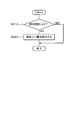
- FIG. 2 is a flowchart of detection control of sleepiness depth and control executed according to the sleepiness depth
- FIG. 3 is a table showing the definition of sleepiness depth
- FIG. 4 is a diagram (part 1) showing a display example of sleepiness warning advice
- FIG. 5 is a diagram (part 2) showing a display example of sleepiness warning advice
- FIG. 6 is a diagram (part 3) showing a display example of sleepiness warning advice
- FIG. 7 is a flowchart of control of process 1
- FIG. 7 is a flowchart of control of process 2
- FIG. 7 is a flowchart of control of process 3
- FIG. 10 shows a second embodiment and is a diagram showing a table of definition of the degree of eye opening.
- FIG. 1 is a block diagram showing an overall schematic configuration of a vehicle system 1 of the present embodiment.
- the vehicle system 1 constitutes a vehicle driving support device.
- the vehicle system 1 includes a vehicle travel control unit 2 that controls travel of the vehicle, and an on-board information control unit 3 that controls information communicated between various on-vehicle devices.
- the vehicle travel control unit 2 includes an out-of-vehicle photographing camera 4, a position measurement device 5, a radar 6, a travel control device 7, and a data processing unit 8 for DSM.
- the outside-of-vehicle photographing camera 4 photographs the periphery of the vehicle and outputs the photographed outside-vehicle image to the traveling control device 7.
- the position measurement device 5 is configured of a GPS receiver or the like, detects the current position of the vehicle, and outputs the detected current position signal to the traveling control device 7.
- the radar 6 detects the other vehicle existing around the vehicle, and outputs the detected information of the other vehicle, that is, information specifying the position of the other vehicle such as position information, distance information, angle information, etc. to the traveling control device 7 Do.
- the traveling control device 7 receives each of the detection signals and the signal output from the data processing unit 8 for DSM, and drives and controls the function as a car navigation device and the engine, brakes, steering, etc. of the vehicle. It has a function to perform automatic driving control of the vehicle.
- the DSM data processing unit 8 inputs the image data from the outside photographing camera 4 and the instruction information from the danger degree determination device 9 of the information control unit 3, and outputs a driving switching signal to the traveling control device 7.
- the information control unit 3 includes an information notification device 10, an HMI operator 11, a DSM in-vehicle shooting camera 12, a risk degree determination device 9, a communication control device 14, and an HMI control device 15.
- the information notification device 10 is configured of, for example, a display, an audio output device, and the like, and is a device that displays data or a message received from the HMI control device 15 or outputs it as sound.
- the HMI controller 11 is a device operated by the user, that is, an occupant, and is configured of a touch panel of the display screen, various switches, and the like, and transmits an operation signal, that is, an operation signal to the HMI control device 15 Do.
- the DSM in-vehicle shooting camera 12 has a function of monitoring the driver's state, that is, a function of the DSM (driver status monitor) and a function of shooting the inside of the vehicle.
- the acquired DSM information and the image data obtained by photographing the inside of a car, a driver, and the like are transmitted to the risk determination device 9.
- the DSM in-vehicle imaging camera 12 has a function as a driver monitor unit.
- the hazard level determination device 9 inputs information from the DSM in-vehicle imaging camera 12, information from the DSM data processing unit 8, and information from the communication control device 14, and based on the information, the driver travels the vehicle In particular, it has a function of calculating, that is, detecting and determining the driver's sleepiness depth. In this case, the danger level determination device 9 has a function as a sleepiness depth calculation unit or a sleepiness detection unit.
- the communication control device 14 has a function as a DCM (data communication module), and is configured by communication devices capable of executing inter-vehicle communication, road-to-vehicle communication, VICS communication, mobile telephone network communication, and the like.
- the communication control device 14 transmits the communication information obtained by the above-mentioned various communications to the risk degree determination device 9. Further, the communication control device 14 transmits the information output from the risk level determination device 9 through the various types of communication.
- the HMI control device 15 has a function of generating or controlling, that is, editing data for screen display or audio output, and transmits the generated or edited data to the information notification device 10.
- FIG. 2 shows the contents of control of the information control unit 3.
- the sleepiness depth detection unit of the danger level determination device 13 includes information from the in-vehicle imaging camera 12, information from the DSM data processing unit 8, and information from the communication control device 14. And calculate the sleepiness depth n of the driver based on the above information.
- the sleepiness depth n numerical values from 0 to 5 are defined, and the contents of the definition are shown in the table of FIG.
- the sleepiness depth 0 is a state in which the driver does not seem completely sleepy, and as the facial expression of the driver's face movement of eye gaze is fast and frequent, the blink cycle of the eye is stable The movement is active and involves movement of the body.
- the sleepiness depth 1 is an operation state in which the driver is slightly sleepy, and the facial expression of the driver is such that the lips are open and the movement of eye movement is slow.
- Sleepiness level 2 is a state where the driver is sleepy, and the driver's facial expression and body movement are said to blink slowly and frequently, have mouth movements, sit back, hand on the face, etc. It is like the operating condition.
- Drowsiness depth 3 is a state in which the driver is quite sleepy, and there are blinks that seem to be conscious as facial expressions of the driver's face and body movements, blinks and gaze movements are slow, head shake, shoulder There is useless physical movement such as up and down movement, yawning is frequent, and deep breathing is also seen.
- Sleepiness level 4 is an extremely sleepy state of the driver, and the driver's facial expression and body movement close the eyelids for a few seconds, head tilts forward, head falls backwards, etc. It is a state.
- the sleepiness depth 5 is a state in which the driver is sleeping, and is an expression operation state such as closing the eyelid for a few seconds as an operation of the facial expression of the driver.
- the driver's drowsiness depth is detected based on information from the in-vehicle photographing camera 12, for example, image data of the driver's face, body, etc., for example, continuously photographed moving image information and the table of FIG. That is, it is configured to determine.
- the sleepiness depth n is represented not only by integer values from 0 to 5 but also by decimal values obtained by equally dividing between integer values by 10, for example. Also, although the sleepiness depth n is configured to be set to six stages from 0 to 5, it is not limited to this, and is configured to be configured to three to five stages or seven or more stages. It is good.
- step S ⁇ b> 20 the danger level determination device 13 transmits the calculation result, that is, the detected sleepiness depth n to the HMI control device 15.
- step S30 the HMI control device 15 generates a sleepiness warning advice message, for example, a sleepiness warning advice message as shown in FIG. 4, FIG. 5 and FIG. 6, based on the received sleepiness depth n.
- step S40 the HMI control device 15 transmits the generated message of the sleepiness warning advice to the information notification device 10.
- step S50 it is determined whether the sleepiness depth n is 2 ⁇ n ⁇ 3. If it is determined in step S50 that the sleepiness depth is 2, that is, the sleepiness depth is a low level (YES), the process proceeds to step S60 to execute processing 1. The contents of this process 1 will be described later. When execution of process 1 is completed, the present control is ended.
- step S50 when the sleepiness depth n is not 2 ⁇ n ⁇ 3 (NO), the process proceeds to step S70, and it is determined whether the sleepiness depth n is 3 ⁇ n ⁇ 4. In this step S70, if the sleepiness depth is 3, ie, the sleepiness depth is at the middle level (YES), the process proceeds to step S80, and the processing 2 is executed. The contents of this process 2 will be described later. When execution of process 2 is completed, this control is ended.
- step S70 when the sleepiness depth n is not 3 ⁇ n ⁇ 4 (NO), the process proceeds to step S90, and it is determined whether the sleepiness depth n is 4 ⁇ n. In this step S90, if the sleepiness depth is 4, ie, the sleepiness depth is at a high level (YES), the process proceeds to step S100, and processing 3 is executed. The contents of this process 3 will be described later. When the execution of the process 3 is completed, the present control is ended.
- step S90 when the sleepiness depth n is not 4 ⁇ n, that is, when the sleepiness depth is less than 2, the driver looks completely sleepy or slightly sleepy, so proceed to “NO”, This control ends without executing anything.
- FIG. 7 is a flowchart showing control contents of a subroutine for executing process 1.
- step S210 of FIG. 7 it is determined whether the sleepiness depth n is n ⁇ 2.
- step S220 the information notification device 10 of the information control unit 3 displays a message of sleepiness warning advice on the screen of the display as shown in FIG. Display a warning message that drowsiness has been detected, and urge the driver to wake up, for example, take a break. The driver sees the warning message and tries to take a break to wake up.
- step S220 the present control is ended. If, in step S210, the sleepiness depth n is less than 2, the process proceeds to "NO", and the present control is ended.
- step S80 The control of the process 2 of step S80, that is, the control when the sleepiness depth n is 3, will be described with reference to the flowchart of FIG. FIG. 8 is a flowchart showing control contents of a subroutine for executing the process 2.
- step S310 in FIG. 8 it is determined whether the sleepiness depth n is n ⁇ 3.
- step S320 the process proceeds to step S320, and the information notification apparatus 10 of the information control unit 3 displays a warning message on the screen of the display as shown in FIG. , There is an obstacle to safe driving (all together, give some five sense stimulation and aim at awakening) "and display the message. Subsequently, the process proceeds to step S330, and the information control unit 3 executes a process of stimulating the sense of five of the driver to wake up the driver. In this case, the following stimulation is executed as processing to stimulate five senses.
- the air volume of the air conditioner is made strong, and the skin temperature is lowered to promote awakening.
- a loud warning sound or a loud warning sound or the like is output to promote awakening.
- "voice message such as” Please be careful with driving because sleepiness depth is high "is output as a warning voice.
- a high voltage current is applied to the steering wheel or the like to apply a high voltage current to the driver's hand, thereby stimulating the sense of touch and promoting awakening.
- the seat heater at the driver's seat is made strong to give high heat to the driver, that is, to increase the skin temperature of the driver and promote awakening.
- the seat cooling device may be made strong to provide cold heat to the driver, that is, to lower the skin temperature of the driver and promote awakening.
- a stimulating odor is generated from steering or the like to stimulate the sense of smell of the driver and promote awakening.
- the five stimulation processes described above may be configured to be all executed in step S330, or one to four of the five stimulation processes may be appropriately selected and executed. Also good.
- step S330 when the sleepiness depth n is less than 3, the process proceeds to "NO", and the present control is ended.
- FIG. 9 is a flow chart showing control contents of a subroutine for executing the process 3.
- step S410 in FIG. 9 it is determined whether the sleepiness depth n is n ⁇ 4.
- step S420 the process proceeds to step S420, and the information notification device 10 of the information control unit 3 displays a warning message on the screen of the display as shown in FIG. Change the mode to evacuation mode (In addition, sound an alarm and change from manual operation mode to automatic operation mode. Inform the surrounding vehicles of the operation mode change).
- step S430 the information control unit 3 switches to the retraction mode, that is, the automatic operation mode.
- the danger degree determination device 9 of the information control unit 3 transmits, to the traveling control device 7 of the traveling control unit 2, instruction information instructing to switch to the automatic operation mode.
- the traveling control device 7 receives the instruction information, switches to the automatic driving mode, and executes the automatic driving.
- the traveling control device 7 transmits information indicating that the automatic driving has been switched to the degree-of-risk determination device 9 of the information control unit 3.
- step S440 the danger degree determination device 9 of the information control unit 3 receives information indicating whether the driving mode has been changed to the retraction mode, that is, switching from the traveling control device 7 to the automatic driving mode. Determine if you If it is determined in step S440 that the mode is changed to the save mode (YES), the process proceeds to step S450, and the risk level determination device 9 of the information control unit 3 operates the save mode in the operation mode via the communication control device 14. Information indicating that the driving mode has been changed is transmitted to the surrounding vehicles via inter-vehicle communication, that is, notification is given. If it is determined in step S440 that the mode is not changed to the retraction mode (NO), the process returns to step S430, and the control described above is repeatedly executed.
- step S460 the traveling control device 7 determines whether there is an area that can be safely stopped around the current position of the vehicle, that is, a point.
- NO no area that can be safely stopped
- step S460 When there is an area in which safe stopping is possible in step S460, that is, when an area in which safe stopping is possible is found (YES), the process proceeds to step S470, where the traveling control device 7 destinations the safe stopping area. Drive towards the area as In the future, there will be an area where safe stopping is possible, even on expressways.
- step S480 the traveling control device 7 gradually decelerates the vehicle speed while traveling toward the area where safety can be stopped. Then, the process proceeds to step S490, and the traveling control device 7 stops the vehicle in an area where it can be safely stopped. This ends this control.
- step S410 when the sleepiness depth n is less than 4, the process proceeds to "NO", and the present control is finished.
- the state of the driver is monitored by the in-vehicle photographing camera 12, and the drowsiness depth of the driver is detected based on the state of the driver monitored by the danger degree determination device 9, and the information control unit
- the system is configured to select and execute the process corresponding to the level of sleepiness of the detected driver from among a plurality of processes for waking up the driver by 3.
- the driver when the driver causes drowsiness, the driver can be surely warned according to the drowsiness level of the driver, that is, the level of drowsiness, and the driver is awakened. It is also possible to enhance the safety sufficiently.
- the information control unit 3 executes a process of displaying a warning message on the screen when the sleepiness depth is at a low level, and stimulates five senses of the driver when the sleepiness depth is at a middle level. The process is executed, and when the sleepiness depth is at a high level, the operation mode is switched to the retraction mode, and the process of automatically stopping the vehicle is executed. According to this configuration, it is possible to wake up the driver, to increase the safety, or to execute the optimal sleepiness measures according to the level of sleepiness of the driver.
- control to lower the temperature of the skin by increasing the air volume of the air conditioner control to output warning sound or warning sound, and apply high voltage current to the hand It is configured to execute control to increase the temperature of the skin by making the seat heater strong, or control to generate an irritating odor to stimulate the sense of smell. According to this configuration, it is possible to wake up the driver by executing the processing for stimulating each of the five senses when the driver's sleepiness depth is 3.
- the facial expression of the driver and the motion of the body are photographed by the in-vehicle photographing camera 12 and divided into three or more levels and detected based on the photographed image information. Configured. According to this configuration, it is possible to select and execute an appropriate control according to the level of sleepiness from among three or more controls.
- the information control unit 3 when the driving mode is switched to the retraction mode, the information control unit 3 is configured to notify the surrounding vehicles of the switching to the retraction mode. According to this configuration, the surrounding vehicles can clearly recognize the vehicles whose driving mode has been switched to the retraction mode, that is, the vehicles whose sleepiness depth n of the driver is 4 or more. It can be careful and can enhance safety.
- FIG. 10 shows a second embodiment.
- the same components as those in the first embodiment are denoted by the same reference numerals.
- the drowsiness depth n of the driver is detected, and the drowsiness determination of the driver is divided into three stages according to the value of the drowsiness depth n, and instead, the second embodiment is replaced by this.
- the drowsiness level of the driver is determined in three stages based on the eye opening degree and the eye opening time of the driver's eyes.
- an opening degree is defined as an eye opening degree which is output in percent.
- the eye opening degree a representative value is obtained from the eye opening degree of each of the left and right eyes and each of the left and right eyes.
- the eye-opening degree representative value is used for the closed eye determination and the drowsiness determination.
- the degree of eye opening is output with a high resolution of, for example, 1% so that the sensitivity of the closed eye determination can be adjusted.
- smiles and anti-glare expressions treatment is performed so as not to make an erroneous determination of closed eyes.
- the eye opening degree is normalized, and the eye opening degrees 100%, 0%, and 120% are defined as shown in the table of FIG.
- the eye opening degree 100% is the average eye opening at the beginning of driving, that is, the eye opening in the normal state.
- the degree of eye opening 0% is the degree of eye opening with the eyes closed.
- the eye opening degree of 120% is the eye opening degree in a normal state, that is, the eye opening degree in a state where the eye opening degree is 100% open.
- the threshold value of the eye opening degree is 0 to 120 (%), and the resolution is 1 (%).
- the following three steps, ie, level 1, level 2 and level 3 are determined, ie, detected, based on the eye opening degree and the eye opening time as the determination of the drowsiness degree of the driver. did.
- the level 1 of the drowsiness level for example, if the eye state with an eye opening degree of 0% continues for 1 second to 2 seconds for a frequency of twice or more in 30 seconds, the drowsiness It is determined that the degree is level 1.
- the state of the eye with an eye opening degree of 0% continues for a time of around 2 seconds, even if it occurs once, it is determined that the snoozing degree is level 2. Also, for example, if the state of the eye with an eye opening degree of 0% continues for about 4 seconds, even if it occurs once, it is determined that the snoozing degree is level 3.
- processing 1 described in the first embodiment is executed.
- processing 2 described in the first embodiment is executed.
- processing 3 described in the first embodiment is executed.
- the configuration of the second embodiment other than that described above is the same as the configuration of the first embodiment. Therefore, also in the second embodiment, substantially the same effect as that of the first embodiment can be obtained.
- the driver's level of sleepiness is divided into three levels and determined.
- the present invention is not limited to this, and may be divided into two levels and determined. The determination may be made in four or more stages.
- the DSM data processing unit 8 is provided on the vehicle travel control unit 2 side, but instead of this, the DSM data processing unit 8 is provided on the information control unit 3 side. You may configure.
Abstract
A vehicular driving assistance device that comprises: a driver monitoring unit 12 that monitors the state of a driver; a sleepiness detection unit 9 that, on the basis of the monitored state of the driver, detects the depth of the sleepiness of the driver or the extent to which the driver is dozing off; and a control unit 3 that, from among a plurality of processes for waking the driver up, selects and executes a process that corresponds to the level of the detected depth of the sleepiness of the driver or extent to which the driver is dozing off.
Description
本出願は、2017年10月12日に出願された日本出願番号2017-198467号に基づくもので、ここにその記載内容を援用する。
This application is based on Japanese Patent Application No. 2017-198467 filed on October 12, 2017, the contents of which are incorporated herein by reference.
本開示は、車両用運転支援装置に関する。
The present disclosure relates to a vehicle driving support device.
特許文献1には、車載カメラで撮影した運転者の画像を認識して、運転者の眠気を判定し、運転者の眠気が強くなったときに、音と振動を発生させることにより、運転者の覚醒を促すシステムが記載されている。
Patent Document 1 recognizes the driver's image taken by the on-vehicle camera, determines the driver's drowsiness, and generates sound and vibration when the driver's drowsiness becomes strong. Describes a system that promotes awakening of
しかし、上記従来構成の場合、音や振動で運転者が覚醒することもあるが、音や振動だけでは、運転者が覚醒しない場合もあるから、安全性が十分であるとは言えなかった。また、音や振動が発生しても、運転者は何が起こったか分からないことがあり、どのように対応したらよいか分からず、混乱するおそれもあった。
However, in the case of the above-described conventional configuration, the driver may be awakened by sound or vibration, but since the driver may not be awakened only by sound or vibration, it can not be said that the safety is sufficient. In addition, even if sounds or vibrations occur, the driver may not know what happened, and there was a fear that he might be confused because he did not know how to respond.
本開示は、運転者が眠気を催したときに、運転者に確実に警告することができ、また、運転者を覚醒させることができ、また、安全性を十分に高めることができる車両用運転支援装置を提供することにある。
The present disclosure can reliably warn the driver when the driver is drowsy, and can awaken the driver and can sufficiently enhance the safety. It is in providing a support device.
本開示の第一の態様において、ドライバの状態をモニタするドライバモニタ部と、モニタされたドライバの状態に基づいてドライバの眠気深度または居眠りの度合を検出する眠気検出部と、ドライバを覚醒させるための複数の処理の中から、検出されたドライバの眠気深度または居眠りの度合のレベルに対応する処理を選択して実行する制御部とを備えるように構成されている。
In a first aspect of the present disclosure, a driver monitor unit that monitors a state of a driver, a sleepiness detection unit that detects a sleepiness depth or a degree of sleepiness of the driver based on the monitored state of the driver, and awakening the driver And a control unit that selects and executes a process corresponding to the level of sleepiness or the level of drowsiness of the detected driver from among the plurality of processes of (4).
本開示についての上記目的およびその他の目的、特徴や利点は、添付の図面を参照しながら下記の詳細な記述により、より明確になる。その図面は、
図1は、第1実施形態を示す車両システムのブロック図であり、
図2は、眠気深度の検出制御及び眠気深度に応じて実行する制御のフローチャートであり、
図3は、眠気深度の定義の表を示す図であり、
図4は、眠気警告アドバイスの表示例を示す図(その1)であり、
図5は、眠気警告アドバイスの表示例を示す図(その2)であり、
図6は、眠気警告アドバイスの表示例を示す図(その3)であり、
図7は、処理1の制御のフローチャートであり、
図7は、処理2の制御のフローチャートであり、
図7は、処理3の制御のフローチャートであり、
図10は、第2実施形態を示すもので、開眼度の定義の表を示す図である。
The above object and other objects, features and advantages of the present disclosure will become more apparent from the following detailed description with reference to the attached drawings. The drawing is
FIG. 1 is a block diagram of a vehicle system showing a first embodiment, FIG. 2 is a flowchart of detection control of sleepiness depth and control executed according to the sleepiness depth, FIG. 3 is a table showing the definition of sleepiness depth; FIG. 4 is a diagram (part 1) showing a display example of sleepiness warning advice; FIG. 5 is a diagram (part 2) showing a display example of sleepiness warning advice; FIG. 6 is a diagram (part 3) showing a display example of sleepiness warning advice; FIG. 7 is a flowchart of control of process 1; FIG. 7 is a flowchart of control of process 2; FIG. 7 is a flowchart of control of process 3; FIG. 10 shows a second embodiment and is a diagram showing a table of definition of the degree of eye opening.
(第1実施形態)
以下、第1実施形態について、図1ないし図9を参照して説明する。図1は、本実施形態の車両システム1の全体概略構成を示すブロック図である。この車両システム1は、車両用運転支援装置を構成する。車両システム1は、車両の走行を制御する車両走行制御部2と、各種の車載装置間で通信される情報を制御する車載情報制御部3とを備えている。 First Embodiment
Hereinafter, the first embodiment will be described with reference to FIGS. 1 to 9. FIG. 1 is a block diagram showing an overall schematic configuration of a vehicle system 1 of the present embodiment. The vehicle system 1 constitutes a vehicle driving support device. The vehicle system 1 includes a vehicletravel control unit 2 that controls travel of the vehicle, and an on-board information control unit 3 that controls information communicated between various on-vehicle devices.
以下、第1実施形態について、図1ないし図9を参照して説明する。図1は、本実施形態の車両システム1の全体概略構成を示すブロック図である。この車両システム1は、車両用運転支援装置を構成する。車両システム1は、車両の走行を制御する車両走行制御部2と、各種の車載装置間で通信される情報を制御する車載情報制御部3とを備えている。 First Embodiment
Hereinafter, the first embodiment will be described with reference to FIGS. 1 to 9. FIG. 1 is a block diagram showing an overall schematic configuration of a vehicle system 1 of the present embodiment. The vehicle system 1 constitutes a vehicle driving support device. The vehicle system 1 includes a vehicle
車両走行制御部2は、車外撮影カメラ4と、位置計測装置5と、レーダ6と、走行制御装置7と、DSM用データ処理部8とを備えている。車外撮影カメラ4は、車両の周辺を撮影し、撮影した車外画像を走行制御装置7へ出力する。位置計測装置5は、GPS受信機等で構成され、車両の現在位置を検出して、検出した現在位置信号を走行制御装置7へ出力する。
The vehicle travel control unit 2 includes an out-of-vehicle photographing camera 4, a position measurement device 5, a radar 6, a travel control device 7, and a data processing unit 8 for DSM. The outside-of-vehicle photographing camera 4 photographs the periphery of the vehicle and outputs the photographed outside-vehicle image to the traveling control device 7. The position measurement device 5 is configured of a GPS receiver or the like, detects the current position of the vehicle, and outputs the detected current position signal to the traveling control device 7.
レーダ6は、車両の周辺に存在する他車両を検出し、検出した他車両の情報、即ち、他車両の位置を特定する情報例えば位置情報や距離情報や角度情報等を走行制御装置7へ出力する。走行制御装置7は、上記各検出信号と、DSM用データ処理部8から出力される信号とを入力し、カーナビゲーション装置としての機能と、車両のエンジン、ブレーキ、ステアリング等を駆動制御することにより車両を自動運転制御する機能とを有している。DSM用データ処理部8は、車外撮影カメラ4からの画像データと、情報制御部3の危険度判定装置9からの指示情報とを入力し、走行制御装置7へ運転切替信号を出力する。
The radar 6 detects the other vehicle existing around the vehicle, and outputs the detected information of the other vehicle, that is, information specifying the position of the other vehicle such as position information, distance information, angle information, etc. to the traveling control device 7 Do. The traveling control device 7 receives each of the detection signals and the signal output from the data processing unit 8 for DSM, and drives and controls the function as a car navigation device and the engine, brakes, steering, etc. of the vehicle. It has a function to perform automatic driving control of the vehicle. The DSM data processing unit 8 inputs the image data from the outside photographing camera 4 and the instruction information from the danger degree determination device 9 of the information control unit 3, and outputs a driving switching signal to the traveling control device 7.
情報制御部3は、情報報知装置10と、HMI操作器11と、DSM車内撮影カメラ12と、危険度判定装置9と、通信制御装置14と、HMI制御装置15とを備えている。情報報知装置10は、例えば表示器や音声出力装置等で構成されており、HMI制御装置15から受け取ったデータやメッセージ等を表示したり、音声で出力したりする装置である。
The information control unit 3 includes an information notification device 10, an HMI operator 11, a DSM in-vehicle shooting camera 12, a risk degree determination device 9, a communication control device 14, and an HMI control device 15. The information notification device 10 is configured of, for example, a display, an audio output device, and the like, and is a device that displays data or a message received from the HMI control device 15 or outputs it as sound.
HMI操作器11は、ユーザ、即ち、乗員が操作する装置であり、表示器の画面のタッチパネルや各種のスイッチ等で構成されており、操作した結果、即ち、操作信号をHMI制御装置15に送信する。DSM車内撮影カメラ12は、ドライバの状態を監視する装置、即ち、DSM(ドライバステータスモニタ)としての機能と、車内を撮影するカメラとしての機能を有しており、このDSM車内撮影カメラ12により得られたDSM情報と、車内やドライバ等を撮影した画像データとは、危険度判定装置9に送信される。DSM車内撮影カメラ12は、ドライバモニタ部としての機能を有する。
The HMI controller 11 is a device operated by the user, that is, an occupant, and is configured of a touch panel of the display screen, various switches, and the like, and transmits an operation signal, that is, an operation signal to the HMI control device 15 Do. The DSM in-vehicle shooting camera 12 has a function of monitoring the driver's state, that is, a function of the DSM (driver status monitor) and a function of shooting the inside of the vehicle. The acquired DSM information and the image data obtained by photographing the inside of a car, a driver, and the like are transmitted to the risk determination device 9. The DSM in-vehicle imaging camera 12 has a function as a driver monitor unit.
危険度判定装置9は、DSM車内撮影カメラ12からの情報と、DSM用データ処理部8からの情報と、通信制御装置14からの情報とを入力し、これら情報に基づいて、ドライバによる車両走行の危険度、具体的には、ドライバの眠気深度を演算、即ち、検出して判定する機能を有する。この場合、危険度判定装置9は、眠気深度演算部または眠気検出部としての機能を有する。
The hazard level determination device 9 inputs information from the DSM in-vehicle imaging camera 12, information from the DSM data processing unit 8, and information from the communication control device 14, and based on the information, the driver travels the vehicle In particular, it has a function of calculating, that is, detecting and determining the driver's sleepiness depth. In this case, the danger level determination device 9 has a function as a sleepiness depth calculation unit or a sleepiness detection unit.
通信制御装置14は、DCM(データコミュニケーションモジュール)としての機能を有し、車車間通信、路車間通信、VICS通信、携帯電話網通信等を実行可能な通信機器で構成されている。通信制御装置14は、上記各種の通信により得られた通信情報を、危険度判定装置9に送信する。また、通信制御装置14は、危険度判定装置9から出力された情報を上記各種の通信を介して送信する。HMI制御装置15は、画面表示または音声出力のためのデータを生成または制御、即ち、編集する機能を有し、生成または編集したデータを情報報知装置10に送信する。
The communication control device 14 has a function as a DCM (data communication module), and is configured by communication devices capable of executing inter-vehicle communication, road-to-vehicle communication, VICS communication, mobile telephone network communication, and the like. The communication control device 14 transmits the communication information obtained by the above-mentioned various communications to the risk degree determination device 9. Further, the communication control device 14 transmits the information output from the risk level determination device 9 through the various types of communication. The HMI control device 15 has a function of generating or controlling, that is, editing data for screen display or audio output, and transmits the generated or edited data to the information notification device 10.
次に、上記構成の動作、即ち、ドライバの眠気深度を検出し、検出した眠気深度に応じて実行する制御について、図2ないし図9を参照して説明する。まず、図2のフローチャートは、情報制御部3の制御の内容を示す。
Next, the operation of the above configuration, that is, control for detecting the sleepiness depth of the driver and executing it according to the detected sleepiness depth will be described with reference to FIG. 2 to FIG. First, the flowchart of FIG. 2 shows the contents of control of the information control unit 3.
この図2のステップS10においては、危険度判定装置13の眠気深度検出部は、DSM車内撮影カメラ12からの情報と、DSM用データ処理部8からの情報と、通信制御装置14からの情報とを入力し、これら情報に基づいて、ドライバの眠気深度nを演算して求める。この場合、眠気深度nは、0~5までの数値が定義されており、定義内容を図3の表に示す。
In step S10 of FIG. 2, the sleepiness depth detection unit of the danger level determination device 13 includes information from the in-vehicle imaging camera 12, information from the DSM data processing unit 8, and information from the communication control device 14. And calculate the sleepiness depth n of the driver based on the above information. In this case, as the sleepiness depth n, numerical values from 0 to 5 are defined, and the contents of the definition are shown in the table of FIG.
図3に示すように、眠気深度0は、ドライバが全く眠くなさそうな状態であり、ドライバの顔の表情の動作としては、視線の移動が早く、頻繁である、目の瞬きの周期は安定している、動きが活発で身体の動きを伴う、というような動作状態である。眠気深度1は、ドライバがやや眠そうな状態であり、ドライバの顔の表情の動作としては、唇が開いている、視線移動の動きが遅い、というような動作状態である。
As shown in FIG. 3, the sleepiness depth 0 is a state in which the driver does not seem completely sleepy, and as the facial expression of the driver's face movement of eye gaze is fast and frequent, the blink cycle of the eye is stable The movement is active and involves movement of the body. The sleepiness depth 1 is an operation state in which the driver is slightly sleepy, and the facial expression of the driver is such that the lips are open and the movement of eye movement is slow.
眠気深度2は、ドライバが眠そうな状態であり、ドライバの顔の表情や身体の動作としては、瞬きはゆっくりと頻発、口の動きがある、座り直しがある、顔に手をやる、というような動作状態である。
Sleepiness level 2 is a state where the driver is sleepy, and the driver's facial expression and body movement are said to blink slowly and frequently, have mouth movements, sit back, hand on the face, etc. It is like the operating condition.
眠気深度3は、ドライバがかなり眠そうな状態であり、ドライバの顔の表情や身体の動作としては、意識的と思わる瞬きがある、瞬きも視線の動きも遅い、頭を振る、肩の上下運動などの無用な身体の動きがある、あくびは頻発し、深呼吸も見られる、というような動作状態である。
Drowsiness depth 3 is a state in which the driver is quite sleepy, and there are blinks that seem to be conscious as facial expressions of the driver's face and body movements, blinks and gaze movements are slow, head shake, shoulder There is useless physical movement such as up and down movement, yawning is frequent, and deep breathing is also seen.
眠気深度4は、ドライバが非常に眠そうな状態であり、ドライバの顔の表情や身体の動作としては、瞼を数秒間閉じる、頭が前に傾く、頭が後ろに倒れる、というような動作状態である。
Sleepiness level 4 is an extremely sleepy state of the driver, and the driver's facial expression and body movement close the eyelids for a few seconds, head tilts forward, head falls backwards, etc. It is a state.
眠気深度5は、ドライバが眠っている状態であり、ドライバの顔の表情の動作としては、瞼を数秒間閉じる、というような表情動作状態である。そして、本実施形態では、車内撮影カメラ12からの情報、例えばドライバの顔や身体等の画像データ、例えば連続的に撮影された動画情報と図3の表に基づいて、ドライバの眠気深度を検出、即ち、判定するように構成されている。尚、眠気深度nとしては、0から5までの整数値だけではなく、整数値間を例えば10等分した小数値で表現されるようにもなっている。また、眠気深度nを、0から5までの6段階に設定するように構成したが、これに限られるものではなく、3段階以上5段階以下、または、7段階以上に設定するように構成しても良い。
The sleepiness depth 5 is a state in which the driver is sleeping, and is an expression operation state such as closing the eyelid for a few seconds as an operation of the facial expression of the driver. In the present embodiment, the driver's drowsiness depth is detected based on information from the in-vehicle photographing camera 12, for example, image data of the driver's face, body, etc., for example, continuously photographed moving image information and the table of FIG. That is, it is configured to determine. The sleepiness depth n is represented not only by integer values from 0 to 5 but also by decimal values obtained by equally dividing between integer values by 10, for example. Also, although the sleepiness depth n is configured to be set to six stages from 0 to 5, it is not limited to this, and is configured to be configured to three to five stages or seven or more stages. It is good.
続いて、ステップS20へ進み、危険度判定装置13は、演算結果、即ち、検出された眠気深度nをHMI制御装置15へ送信する。続いて、ステップS30では、HMI制御装置15は、受信した眠気深度nに基づいて眠気警告アドバイス、例えば図4、図5、図6に示すような眠気警告アドバイスのメッセージを生成する。更に、ステップS40へ進み、HMI制御装置15は、上記生成した眠気警告アドバイスのメッセージを情報報知装置10に送信する。
Subsequently, the process proceeds to step S <b> 20, and the danger level determination device 13 transmits the calculation result, that is, the detected sleepiness depth n to the HMI control device 15. Subsequently, in step S30, the HMI control device 15 generates a sleepiness warning advice message, for example, a sleepiness warning advice message as shown in FIG. 4, FIG. 5 and FIG. 6, based on the received sleepiness depth n. Further, the process proceeds to step S40, and the HMI control device 15 transmits the generated message of the sleepiness warning advice to the information notification device 10.
この後、ステップS50へ進み、眠気深度nが、2≦n<3であるか否かを判断する。このステップS50で、眠気深度が2、即ち、眠気深度が低レベルであれば(YES)、ステップS60へ進み、処理1を実行する。この処理1の内容については、後述する。処理1を実行完了すると、本制御を終了する。
Thereafter, the process proceeds to step S50, and it is determined whether the sleepiness depth n is 2 ≦ n <3. If it is determined in step S50 that the sleepiness depth is 2, that is, the sleepiness depth is a low level (YES), the process proceeds to step S60 to execute processing 1. The contents of this process 1 will be described later. When execution of process 1 is completed, the present control is ended.
また、上記ステップS50において、眠気深度nが、2≦n<3でないときには(NO)、ステップS70へ進み、眠気深度nが、3≦n<4であるか否かを判断する。このステップS70で、眠気深度が3、即ち、眠気深度が中レベルであれば(YES)、ステップS80へ進み、処理2を実行する。この処理2の内容については、後述する。処理2を実行完了すると、本制御を終了する。
In step S50, when the sleepiness depth n is not 2 ≦ n <3 (NO), the process proceeds to step S70, and it is determined whether the sleepiness depth n is 3 ≦ n <4. In this step S70, if the sleepiness depth is 3, ie, the sleepiness depth is at the middle level (YES), the process proceeds to step S80, and the processing 2 is executed. The contents of this process 2 will be described later. When execution of process 2 is completed, this control is ended.
また、上記ステップS70において、眠気深度nが、3≦n<4でないときには(NO)、ステップS90へ進み、眠気深度nが、4≦nであるか否かを判断する。このステップS90で、眠気深度が4、即ち、眠気深度が高レベルであれば(YES)、ステップS100へ進み、処理3を実行する。この処理3の内容については、後述する。処理3を実行完了すると、本制御を終了する。
In step S70, when the sleepiness depth n is not 3 ≦ n <4 (NO), the process proceeds to step S90, and it is determined whether the sleepiness depth n is 4 ≦ n. In this step S90, if the sleepiness depth is 4, ie, the sleepiness depth is at a high level (YES), the process proceeds to step S100, and processing 3 is executed. The contents of this process 3 will be described later. When the execution of the process 3 is completed, the present control is ended.
また、上記ステップS90において、眠気深度nが、4≦nでないとき、即ち、眠気深度が2未満のときには、ドライバは全く眠くなさそう、または、やや眠そうであるから、「NO」へ進み、何も実行しないで、本制御を終了する。
Further, in the above step S90, when the sleepiness depth n is not 4 ≦ n, that is, when the sleepiness depth is less than 2, the driver looks completely sleepy or slightly sleepy, so proceed to “NO”, This control ends without executing anything.
次に、上記ステップS60の処理1の制御、即ち、眠気深度nが2のときの制御について、図7のフローチャートを参照して説明する。図7は、処理1を実行するサブルーチンの制御内容を示すフローチャートである。まず、図7のステップS210において、眠気深度nが、n≧2であるか否かを判断する。
Next, the control of process 1 of step S60, that is, the control when the sleepiness depth n is 2, will be described with reference to the flowchart of FIG. FIG. 7 is a flowchart showing control contents of a subroutine for executing process 1. First, in step S210 of FIG. 7, it is determined whether the sleepiness depth n is n ≧ 2.
ここで、眠気深度nが2であるから(YES)、ステップS220へ進み、情報制御部3の情報報知装置10は、図4に示すように、表示器の画面に眠気警告アドバイスのメッセージ例えば「眠気が検知されました」という警告メッセージを表示し、ドライバに覚醒すること、例えば休憩をとることを促す。ドライバは、この警告メッセージを視認することにより、覚醒するために休憩を取ろうとするようになる。
Here, since the sleepiness depth n is 2 (YES), the process proceeds to step S220, and the information notification device 10 of the information control unit 3 displays a message of sleepiness warning advice on the screen of the display as shown in FIG. Display a warning message that drowsiness has been detected, and urge the driver to wake up, for example, take a break. The driver sees the warning message and tries to take a break to wake up.
また、助手席に座っている乗員は、上記警告メッセージを視認することにより、休憩を取ることを、ドライバに促すことができる。尚、上記ステップS220を実行完了すると、本制御を終了する。尚、上記ステップS210において、眠気深度nが2未満であるときには、「NO」へ進み、本制御を終了する。
Further, the passenger sitting in the front passenger seat can urge the driver to take a break by visually recognizing the warning message. When the execution of step S220 is completed, the present control is ended. If, in step S210, the sleepiness depth n is less than 2, the process proceeds to "NO", and the present control is ended.
また、前記ステップS80の処理2の制御、即ち、眠気深度nが3のときの制御について、図8のフローチャートを参照して説明する。図8は、処理2を実行するサブルーチンの制御内容を示すフローチャートである。まず、図8のステップS310において、眠気深度nが、n≧3であるか否かを判断する。
The control of the process 2 of step S80, that is, the control when the sleepiness depth n is 3, will be described with reference to the flowchart of FIG. FIG. 8 is a flowchart showing control contents of a subroutine for executing the process 2. First, in step S310 in FIG. 8, it is determined whether the sleepiness depth n is n ≧ 3.
ここで、眠気深度nが3であるから(YES)、ステップS320へ進み、情報制御部3の情報報知装置10は、図5に示すように、表示器の画面に警告メッセージ例えば「眠気のため、安全運転に支障があります(あわせて、何らかの5感刺激を与えて覚醒を狙う)」というメッセージを表示する。続いて、ステップS330へ進み、情報制御部3は、ドライバの5感を刺激する処理を実行し、ドライバを覚醒させる。この場合、5感を刺激する処理として、次の通りの刺激を実行する。
Here, since the sleepiness depth n is 3 (YES), the process proceeds to step S320, and the information notification apparatus 10 of the information control unit 3 displays a warning message on the screen of the display as shown in FIG. , There is an obstacle to safe driving (all together, give some five sense stimulation and aim at awakening) "and display the message. Subsequently, the process proceeds to step S330, and the information control unit 3 executes a process of stimulating the sense of five of the driver to wake up the driver. In this case, the following stimulation is executed as processing to stimulate five senses.
まず、第1の刺激処理としては、エアコンの風量を強にし、皮膚の温度を下げることで覚醒を促す。第2の刺激処理としては、大きな警告音または大きな警告音声等を出力し、覚醒を促す。この場合、警告音声としては、例えば「眠気深度が高いので運転に注意してください等の音声メッセージ」を出力する。
First, as the first stimulation process, the air volume of the air conditioner is made strong, and the skin temperature is lowered to promote awakening. In the second stimulation process, a loud warning sound or a loud warning sound or the like is output to promote awakening. In this case, for example, "voice message such as" Please be careful with driving because sleepiness depth is high "is output as a warning voice.
第3の刺激処理としては、ステアリング等に高電圧電流を流すことによりドライバの手に高電圧電流を印加して、触覚を刺激し、覚醒を促す。第4の刺激処理としては、運転席のシートヒータを強にして、高熱をドライバに与え、即ち、ドライバの皮膚温度を高め、覚醒を促す。尚、シート冷却装置が設けられている車両の場合には、シート冷却装置を強にして、冷熱をドライバに与え、即ち、ドライバの皮膚温度を低下させ、覚醒を促すように構成しても良い。第5の刺激処理としては、刺激臭をステアリング等から発生させて、ドライバの嗅覚を刺激し、覚醒を促す。
In the third stimulation process, a high voltage current is applied to the steering wheel or the like to apply a high voltage current to the driver's hand, thereby stimulating the sense of touch and promoting awakening. As a fourth stimulation process, the seat heater at the driver's seat is made strong to give high heat to the driver, that is, to increase the skin temperature of the driver and promote awakening. In the case of a vehicle provided with a seat cooling device, the seat cooling device may be made strong to provide cold heat to the driver, that is, to lower the skin temperature of the driver and promote awakening. . In the fifth stimulation process, a stimulating odor is generated from steering or the like to stimulate the sense of smell of the driver and promote awakening.
尚、上記した5つの刺激処理を、上記ステップS330において、全て実行するように構成しても良いし、5つの刺激処理の中から1ないし4つを適宜選択して実行するように構成しても良い。
Note that the five stimulation processes described above may be configured to be all executed in step S330, or one to four of the five stimulation processes may be appropriately selected and executed. Also good.
そして、本実施形態の場合、上記した刺激処理が実行されて、ドライバが覚醒した場合、ドライバは、刺激を受けて、かなり驚くが、表示器に表示された警告メッセージを視認することにより、ドライバの覚醒を促すための刺激処理が実行されたことが容易に分かるようになり、安心感が得られ、戸惑うことがなくなる。また、ドライバは、上記警告メッセージを視認することにより、休憩を取ろうかと思うようになる。また、助手席に座っている乗員は、上記警告メッセージを視認することにより、休憩を取ることを、ドライバに促すことができる。上記ステップS330を実行完了すると、本制御を終了する。
尚、上記ステップS310において、眠気深度nが3未満であるときには、「NO」へ進み、本制御を終了する。 Then, in the case of the present embodiment, when the above-described stimulation processing is executed and the driver wakes up, the driver receives the stimulation and is considerably surprised that the driver visually recognizes the warning message displayed on the display unit. It can be easily understood that the stimulation process for promoting the awakening of the subject has been performed, and a sense of security is obtained and no confusion is caused. Also, the driver can think of taking a break by visually recognizing the warning message. Further, the passenger sitting in the front passenger seat can urge the driver to take a break by visually recognizing the warning message. When the execution of step S330 is completed, the present control is ended.
In the above-described step S310, when the sleepiness depth n is less than 3, the process proceeds to "NO", and the present control is ended.
また、前記ステップS100の処理3の制御、即ち、眠気深度nが4のときの制御について、図9のフローチャートを参照して説明する。図9は、処理3を実行するサブルーチンの制御内容を示すフローチャートである。まず、図9のステップS410において、眠気深度nが、n≧4であるか否かを判断する。
Further, the control of the process 3 of the step S100, that is, the control when the sleepiness depth n is 4, will be described with reference to the flowchart of FIG. FIG. 9 is a flow chart showing control contents of a subroutine for executing the process 3. First, in step S410 in FIG. 9, it is determined whether the sleepiness depth n is n ≧ 4.
ここで、眠気深度nが4であることから(YES)、ステップS420へ進み、情報制御部3の情報報知装置10は、図6に示すように、表示器の画面に警告メッセージ例えば「運転が危険です。退避モードに変更します。(あわせて、警報音を出し、手動運転モードから自動運転モードに変更する。運転モード変更を周辺車両に報知する)」というメッセージを表示する。
Here, since the sleepiness depth n is 4 (YES), the process proceeds to step S420, and the information notification device 10 of the information control unit 3 displays a warning message on the screen of the display as shown in FIG. Change the mode to evacuation mode (In addition, sound an alarm and change from manual operation mode to automatic operation mode. Inform the surrounding vehicles of the operation mode change).
続いて、ステップS430へ進み、情報制御部3は、退避モード、即ち、自動運転モードに切り替える。この場合、情報制御部3の危険度判定装置9は、自動運転モードに切り替えるように指示する指示情報を、走行制御部2の走行制御装置7へ送信する。走行制御装置7は、上記指示情報を入力して、自動運転モードに切り替え、自動運転を実行する。また、走行制御装置7は、自動運転に切り替えたことを示す情報を情報制御部3の危険度判定装置9へ送信する。
Subsequently, the process proceeds to step S430, and the information control unit 3 switches to the retraction mode, that is, the automatic operation mode. In this case, the danger degree determination device 9 of the information control unit 3 transmits, to the traveling control device 7 of the traveling control unit 2, instruction information instructing to switch to the automatic operation mode. The traveling control device 7 receives the instruction information, switches to the automatic driving mode, and executes the automatic driving. In addition, the traveling control device 7 transmits information indicating that the automatic driving has been switched to the degree-of-risk determination device 9 of the information control unit 3.
そして、ステップS440へ進み、情報制御部3の危険度判定装置9は、運転モードが退避モードに変更されたか否か、即ち、走行制御装置7から自動運転モードに切り替えたことを示す情報を受信したか否かを判断する。このステップS440で、退避モードに変更されたときには(YES)、ステップS450へ進み、情報制御部3の危険度判定装置9は、通信制御装置14を介して、運転モードが退避モード、即ち、自動運転モードに変更されたことを示す情報を、車車間通信を介して周辺車両へ送信する、即ち、報知する。尚、上記ステップS440にて、退避モードに変更されなかったときには(NO)、ステップS430へ戻り、上述した制御を繰り返し実行する。
Then, the process proceeds to step S440, and the danger degree determination device 9 of the information control unit 3 receives information indicating whether the driving mode has been changed to the retraction mode, that is, switching from the traveling control device 7 to the automatic driving mode. Determine if you If it is determined in step S440 that the mode is changed to the save mode (YES), the process proceeds to step S450, and the risk level determination device 9 of the information control unit 3 operates the save mode in the operation mode via the communication control device 14. Information indicating that the driving mode has been changed is transmitted to the surrounding vehicles via inter-vehicle communication, that is, notification is given. If it is determined in step S440 that the mode is not changed to the retraction mode (NO), the process returns to step S430, and the control described above is repeatedly executed.
この後、ステップS460からステップS490までの制御は、自動運転モードに切り替えられた後の制御、即ち、走行制御部2の走行制御装置7による制御を示している。まず、ステップS460においては、走行制御装置7は、車両の現在位置の周辺に安全に停止できるエリア、即ち、地点があるか否かを判断する。ここで、安全に停止できるエリアがないときには(NO)、ステップS460の処理を繰り返し実行する。
After this, the control from step S460 to step S490 indicates control after switching to the automatic operation mode, that is, control by the traveling control device 7 of the traveling control unit 2. First, in step S460, the traveling control device 7 determines whether there is an area that can be safely stopped around the current position of the vehicle, that is, a point. Here, when there is no area that can be safely stopped (NO), the process of step S460 is repeatedly executed.
上記ステップS460において、安全に停止できるエリアがあったとき、即ち、安全に停止できるエリアが発見されたときには(YES)、ステップS470へ進み、走行制御装置7は、安全に停止できるエリアを目的地として該エリアに向かって走行する。尚、将来的には、高速道路上においても、安全に停止できるエリアが設置されるようになっている。
When there is an area in which safe stopping is possible in step S460, that is, when an area in which safe stopping is possible is found (YES), the process proceeds to step S470, where the traveling control device 7 destinations the safe stopping area. Drive towards the area as In the future, there will be an area where safe stopping is possible, even on expressways.
続いて、ステップS480へ進み、走行制御装置7は、安全に停止できるエリアに向かって走行しながら、徐々に車速を減速していく。そして、ステップS490へ進み、走行制御装置7は、安全に停止できるエリアで車両を停止させる。これにより、本制御を終了する。
尚、上記ステップS410において、眠気深度nが4未満であるときには、「NO」へ進み、本制御を終了する。 Subsequently, the process proceeds to step S480, and the traveling control device 7 gradually decelerates the vehicle speed while traveling toward the area where safety can be stopped. Then, the process proceeds to step S490, and the traveling control device 7 stops the vehicle in an area where it can be safely stopped. This ends this control.
In step S410, when the sleepiness depth n is less than 4, the process proceeds to "NO", and the present control is finished.
このような構成の本実施形態においては、車内撮影カメラ12によりドライバの状態をモニタし、危険度判定装置9により上記モニタされたドライバの状態に基づいてドライバの眠気深度を検出し、情報制御部3によりドライバを覚醒させるための複数の処理の中から、検出されたドライバの眠気深度のレベルに対応する処理を選択して実行するように構成した。この構成によれば、ドライバが眠気を催したときに、ドライバの眠気の程度、即ち、眠気深度のレベルに応じて、運転者に確実に警告することができ、また、運転者を覚醒させることができ、また、安全性を十分に高めることができる。
In the present embodiment having such a configuration, the state of the driver is monitored by the in-vehicle photographing camera 12, and the drowsiness depth of the driver is detected based on the state of the driver monitored by the danger degree determination device 9, and the information control unit The system is configured to select and execute the process corresponding to the level of sleepiness of the detected driver from among a plurality of processes for waking up the driver by 3. According to this configuration, when the driver causes drowsiness, the driver can be surely warned according to the drowsiness level of the driver, that is, the level of drowsiness, and the driver is awakened. It is also possible to enhance the safety sufficiently.
また、上記実施形態では、情報制御部3によって、眠気深度が低レベルであるときには、画面に警告メッセージを表示する処理を実行し、眠気深度が中レベルであるときには、ドライバの5感を刺激する処理を実行し、眠気深度が高レベルであるときには、運転モードを退避モードに切り替え、車両を自動的に停車させる処理を実行するように構成した。この構成によれば、ドライバの眠気深度のレベルに応じて、ドライバを覚醒させたり、安全性を高くしたり、最適な眠気対策を実行することができる。
In the above embodiment, the information control unit 3 executes a process of displaying a warning message on the screen when the sleepiness depth is at a low level, and stimulates five senses of the driver when the sleepiness depth is at a middle level. The process is executed, and when the sleepiness depth is at a high level, the operation mode is switched to the retraction mode, and the process of automatically stopping the vehicle is executed. According to this configuration, it is possible to wake up the driver, to increase the safety, or to execute the optimal sleepiness measures according to the level of sleepiness of the driver.
更に、上記実施形態によれば、ドライバの5感を刺激する処理として、エアコンの風量を強にして皮膚の温度を下げる制御、警告音または警告音声を出力する制御、手に高電圧電流を印加する制御、シートヒータを強にして皮膚の温度を高める制御、または、刺激臭を発生させて嗅覚を刺激する制御を実行するように構成した。この構成によれば、ドライバの眠気深度3のときに、上記各5感を刺激する処理を実行することにより、ドライバを覚醒させることが可能になる。
Furthermore, according to the above-described embodiment, as processing to stimulate the senses of the driver, control to lower the temperature of the skin by increasing the air volume of the air conditioner, control to output warning sound or warning sound, and apply high voltage current to the hand It is configured to execute control to increase the temperature of the skin by making the seat heater strong, or control to generate an irritating odor to stimulate the sense of smell. According to this configuration, it is possible to wake up the driver by executing the processing for stimulating each of the five senses when the driver's sleepiness depth is 3.
また、上記実施形態では、眠気深度を検出するに際して、ドライバの顔の表情や身体の動作を車内撮影カメラ12で撮影し、撮影した画像情報に基づいて3段階以上のレベルに分けて検出するように構成した。この構成によれば、3つ以上の制御の中から、眠気深度のレベルに応じて適切な制御を選択して実行することができる。
Further, in the above embodiment, when the sleepiness depth is detected, the facial expression of the driver and the motion of the body are photographed by the in-vehicle photographing camera 12 and divided into three or more levels and detected based on the photographed image information. Configured. According to this configuration, it is possible to select and execute an appropriate control according to the level of sleepiness from among three or more controls.
また、上記実施形態では、情報制御部3によって、運転モードを退避モードに切り替えたときには、退避モードに切り替えたことを、周辺の車両に報知するように構成した。この構成によれば、周辺の車両は、運転モードが退避モードに切り替えられた車両、即ち、ドライバの眠気深度nが4以上である車両を明確に認識することができるから、当該車両の運転に注意することができ、安全性を高めることができる。
Further, in the above embodiment, when the driving mode is switched to the retraction mode, the information control unit 3 is configured to notify the surrounding vehicles of the switching to the retraction mode. According to this configuration, the surrounding vehicles can clearly recognize the vehicles whose driving mode has been switched to the retraction mode, that is, the vehicles whose sleepiness depth n of the driver is 4 or more. It can be careful and can enhance safety.
(第2実施形態)
図10は、第2実施形態を示すものである。尚、第1実施形態と同一構成には、同一符号を付している。第1実施形態では、ドライバの眠気深度nを検出し、ドライバの居眠り判定を、眠気深度nの値に応じて3段階に分けて判定するように構成したが、これに代えて、第2実施形態では、ドライバの眼の開眼度と開眼時間に基づいて、ドライバの居眠り度合を、3段階に分けて判定するように構成した。 Second Embodiment
FIG. 10 shows a second embodiment. The same components as those in the first embodiment are denoted by the same reference numerals. In the first embodiment, the drowsiness depth n of the driver is detected, and the drowsiness determination of the driver is divided into three stages according to the value of the drowsiness depth n, and instead, the second embodiment is replaced by this. In the embodiment, the drowsiness level of the driver is determined in three stages based on the eye opening degree and the eye opening time of the driver's eyes.
まず、眼の開眼度の定義について、図10の表も参照して説明する。まず、眼の開度をドライバの眼形状に合せてパーセント単位で出力するものを開眼度として定義する。開眼度としては、左右それぞれの眼、および、左右それぞれの眼の開眼度から代表値を求める。閉眼判定及び眠気判定には、この開眼度代表値を用いる。開眼度は、閉眼判定の感度を調整できるように例えば1%の高分解能で出力されるようになっている。また、笑顔や防眩表情に対して、閉眼誤判定をしないような処置がなされている。更に、眼の開き度合いを正規化し、開眼度100%、0%、120%を、図10の表に示すように定義している。
First, the definition of the degree of eye opening will be described with reference to the table in FIG. First, according to the eye shape of the driver, an opening degree is defined as an eye opening degree which is output in percent. As the eye opening degree, a representative value is obtained from the eye opening degree of each of the left and right eyes and each of the left and right eyes. The eye-opening degree representative value is used for the closed eye determination and the drowsiness determination. The degree of eye opening is output with a high resolution of, for example, 1% so that the sensitivity of the closed eye determination can be adjusted. In addition, for smiles and anti-glare expressions, treatment is performed so as not to make an erroneous determination of closed eyes. Furthermore, the eye opening degree is normalized, and the eye opening degrees 100%, 0%, and 120% are defined as shown in the table of FIG.
図10に示すように、開眼度100%は、運転初期の平均的な眼の開度、即ち、通常状態の眼の開度である。開眼度0%は、眼を閉じている状態の眼の開度である。開眼度120%は、通常状態の眼の開度、即ち、開眼度100%から更に見開いた状態の眼の開度である。そして、開眼度の域値は、0~120(%)であり、分解能は1(%)である。
As shown in FIG. 10, the eye opening degree 100% is the average eye opening at the beginning of driving, that is, the eye opening in the normal state. The degree of eye opening 0% is the degree of eye opening with the eyes closed. The eye opening degree of 120% is the eye opening degree in a normal state, that is, the eye opening degree in a state where the eye opening degree is 100% open. The threshold value of the eye opening degree is 0 to 120 (%), and the resolution is 1 (%).
第2実施形態において、ドライバの居眠り度合の判定としては、開眼度と開眼時間に基づいて、次の3段階、即ち、レベル1、レベル2、レベル3を判定する、即ち、検出するように構成した。まず、居眠り度合のレベル1を判定するに際しては、例えば、開眼度0%である眼の状態が1秒~2秒の時間継続することが、30秒間に2回以上起きる頻度となったら、居眠り度合がレベル1であると判定する。
In the second embodiment, the following three steps, ie, level 1, level 2 and level 3 are determined, ie, detected, based on the eye opening degree and the eye opening time as the determination of the drowsiness degree of the driver. did. First, in determining the level 1 of the drowsiness level, for example, if the eye state with an eye opening degree of 0% continues for 1 second to 2 seconds for a frequency of twice or more in 30 seconds, the drowsiness It is determined that the degree is level 1.
また、例えば、開眼度0%である眼の状態が2秒前後の時間継続することが、1回でも起きたら、居眠り度合がレベル2であると判定する。また、例えば、開眼度0%である眼の状態が4秒前後の時間継続することが、1回でも起きたら、居眠り度合がレベル3であると判定する。
Also, for example, if the state of the eye with an eye opening degree of 0% continues for a time of around 2 seconds, even if it occurs once, it is determined that the snoozing degree is level 2. Also, for example, if the state of the eye with an eye opening degree of 0% continues for about 4 seconds, even if it occurs once, it is determined that the snoozing degree is level 3.
そして、ドライバの居眠り度合がレベル1であると判定された場合、第1実施形態で説明した処理1を実行するようになっている。また、ドライバの居眠り度合がレベル2であると判定された場合、第1実施形態で説明した処理2を実行するようになっている。更に、ドライバの居眠り度合がレベル3であると判定された場合、第1実施形態で説明した処理3を実行するようになっている。
Then, when it is determined that the driver's level of sleepiness is level 1, processing 1 described in the first embodiment is executed. In addition, when it is determined that the drowsiness level of the driver is level 2, processing 2 described in the first embodiment is executed. Furthermore, when it is determined that the driver's level of sleep is level 3, processing 3 described in the first embodiment is executed.
尚、上述した以外の第2実施形態の構成は、第1実施形態の構成と同じ構成となっている。従って、第2実施形態においても、第1実施形態とほぼ同じ作用効果を得ることができる。
The configuration of the second embodiment other than that described above is the same as the configuration of the first embodiment. Therefore, also in the second embodiment, substantially the same effect as that of the first embodiment can be obtained.
また、上記各実施形態では、ドライバの居眠り度合を3段階に分けて判定するように構成したが、これに限られるものではなく、2段階に分けて判定するように構成しても良いし、4段階以上に分けて判定するように構成しても良い。
また、上記各実施形態では、DSM用データ処理部8を車両走行制御部2側に設けるように構成したが、これに代えて、DSM用データ処理部8を情報制御部3側に設けるように構成しても良い。 In each of the above-described embodiments, the driver's level of sleepiness is divided into three levels and determined. However, the present invention is not limited to this, and may be divided into two levels and determined. The determination may be made in four or more stages.
In the above embodiments, the DSM data processing unit 8 is provided on the vehicletravel control unit 2 side, but instead of this, the DSM data processing unit 8 is provided on the information control unit 3 side. You may configure.
また、上記各実施形態では、DSM用データ処理部8を車両走行制御部2側に設けるように構成したが、これに代えて、DSM用データ処理部8を情報制御部3側に設けるように構成しても良い。 In each of the above-described embodiments, the driver's level of sleepiness is divided into three levels and determined. However, the present invention is not limited to this, and may be divided into two levels and determined. The determination may be made in four or more stages.
In the above embodiments, the DSM data processing unit 8 is provided on the vehicle
本開示は、実施例に準拠して記述されたが、本開示は当該実施例や構造に限定されるものではないと理解される。本開示は、様々な変形例や均等範囲内の変形をも包含する。加えて、様々な組み合わせや形態、さらには、それらに一要素のみ、それ以上、あるいはそれ以下、を含む他の組み合わせや形態をも、本開示の範疇や思想範囲に入るものである。
Although the present disclosure has been described based on the examples, it is understood that the present disclosure is not limited to the examples and structures. The present disclosure also includes various modifications and variations within the equivalent range. In addition, various combinations and forms, and further, other combinations and forms including only one element, or more or less than these elements are also within the scope and the scope of the present disclosure.
Claims (5)
- ドライバの状態をモニタするドライバモニタ部(12)と、
モニタされたドライバの状態に基づいてドライバの眠気深度または居眠りの度合を検出する眠気検出部(9)と、
ドライバを覚醒させるための複数の処理の中から、検出されたドライバの眠気深度または居眠りの度合のレベルに対応する処理を選択して実行する制御部(3)と
を備えた車両用運転支援装置。 A driver monitor unit (12) that monitors the state of the driver;
A sleepiness detection unit (9) for detecting the sleepiness depth or the degree of sleepiness of the driver based on the monitored status of the driver;
A control unit (3) for a vehicle including: a control unit (3) that selects and executes a process corresponding to the level of sleepiness or the level of drowsiness of the detected driver among a plurality of processes for awakening the driver; . - 前記制御部は、眠気深度が低レベルであるときには、画面に警告メッセージを表示する処理を実行し、眠気深度が中レベルであるときには、ドライバの5感を刺激する処理を実行し、眠気深度が高レベルであるときには、運転モードを退避モードに切り替え、車両を自動的に停車させる処理を実行するように構成された請求項1記載の車両用運転支援装置。 The control unit executes a process of displaying a warning message on the screen when the sleepiness depth is low, and executes a process of stimulating the driver's five senses when the sleepiness depth is medium, and the sleepiness depth is 2. The driving support system for a vehicle according to claim 1, wherein when the driving level is high, the driving mode is switched to the retraction mode, and processing for automatically stopping the vehicle is executed.
- ドライバの5感を刺激する処理は、エアコンの風量を強にして皮膚の温度を下げる制御、警告音または警告音声を出力する制御、手に高電圧電流を印加する制御、シートヒータを強にして皮膚の温度を高める制御、または、刺激臭を発生させて嗅覚を刺激する制御である請求項1または2記載の車両用運転支援装置。 The process of stimulating the driver's five senses is to increase the air volume of the air conditioner and lower the skin temperature, control to output a warning sound or sound, control to apply a high voltage current to the hand, and increase the seat heater. 3. The driving support system for a vehicle according to claim 1, wherein the control for increasing the temperature of the skin or the control for generating an irritating odor to stimulate the sense of smell.
- 眠気深度は、ドライバの顔の表情や身体の動作をカメラで撮影し、撮影した画像情報に基づいて3段階以上のレベルに分けて検出されるように構成された請求項1から3のいずれか一項記載の車両用運転支援装置。 4. The drowsiness depth according to any one of claims 1 to 3, wherein the facial expression of the driver and the motion of the body are captured by a camera and detected in three or more levels based on the captured image information. The driving assistance device for a vehicle according to any one of the above.
- 前記制御部は、運転モードを退避モードに切り替えたときには、退避モードに切り替えたことを、周辺の車両に報知するように構成された請求項2記載の車両用運転支援装置。
The driving support apparatus for a vehicle according to claim 2, wherein the control unit is configured to notify surrounding vehicles of switching to the retraction mode when switching the driving mode to the retraction mode.
Priority Applications (2)
| Application Number | Priority Date | Filing Date | Title |
|---|---|---|---|
| DE112018004487.4T DE112018004487T5 (en) | 2017-10-12 | 2018-08-28 | VEHICLE DRIVING ASSISTANT DEVICE |
| US16/822,603 US20200216095A1 (en) | 2017-10-12 | 2020-03-18 | Vehicle driving assistance apparatus |
Applications Claiming Priority (2)
| Application Number | Priority Date | Filing Date | Title |
|---|---|---|---|
| JP2017198467A JP2019074791A (en) | 2017-10-12 | 2017-10-12 | Driving support device for vehicle |
| JP2017-198467 | 2017-10-12 |
Related Child Applications (1)
| Application Number | Title | Priority Date | Filing Date |
|---|---|---|---|
| US16/822,603 Continuation US20200216095A1 (en) | 2017-10-12 | 2020-03-18 | Vehicle driving assistance apparatus |
Publications (1)
| Publication Number | Publication Date |
|---|---|
| WO2019073708A1 true WO2019073708A1 (en) | 2019-04-18 |
Family
ID=66101395
Family Applications (1)
| Application Number | Title | Priority Date | Filing Date |
|---|---|---|---|
| PCT/JP2018/031750 WO2019073708A1 (en) | 2017-10-12 | 2018-08-28 | Vehicular driving assistance device |
Country Status (4)
| Country | Link |
|---|---|
| US (1) | US20200216095A1 (en) |
| JP (1) | JP2019074791A (en) |
| DE (1) | DE112018004487T5 (en) |
| WO (1) | WO2019073708A1 (en) |
Cited By (2)
| Publication number | Priority date | Publication date | Assignee | Title |
|---|---|---|---|---|
| EP3875330A1 (en) * | 2020-03-04 | 2021-09-08 | Toyota Jidosha Kabushiki Kaisha | Vehicle controller |
| WO2022124163A1 (en) * | 2020-12-11 | 2022-06-16 | 株式会社デンソー | Awakening device, and awakening stimulus control method |
Families Citing this family (7)
| Publication number | Priority date | Publication date | Assignee | Title |
|---|---|---|---|---|
| US11361560B2 (en) * | 2018-02-19 | 2022-06-14 | Mitsubishi Electric Corporation | Passenger state detection device, passenger state detection system, and passenger state detection method |
| KR102630485B1 (en) * | 2019-06-18 | 2024-02-01 | 엘지전자 주식회사 | Vehicle control methods |
| JP2021033508A (en) * | 2019-08-21 | 2021-03-01 | 株式会社東海理化電機製作所 | Information notification device, control device, and computer program |
| JP2021033506A (en) * | 2019-08-21 | 2021-03-01 | 株式会社東海理化電機製作所 | Moving support device, controller, and computer program |
| CN112569447B (en) * | 2020-12-17 | 2023-07-11 | 大陆投资(中国)有限公司 | Sleep assistance method for vehicle user and in-vehicle infotainment system |
| CN113516015B (en) * | 2021-04-15 | 2023-12-05 | 广东工业大学 | Emotion recognition method, driving assisting device and application |
| JP7460867B2 (en) | 2021-12-24 | 2024-04-03 | パナソニックオートモーティブシステムズ株式会社 | Estimation device, estimation method, and program |
Citations (2)
| Publication number | Priority date | Publication date | Assignee | Title |
|---|---|---|---|---|
| JP2005062911A (en) * | 2003-06-16 | 2005-03-10 | Fujitsu Ten Ltd | Vehicle controller |
| JP2012245091A (en) * | 2011-05-26 | 2012-12-13 | Panasonic Corp | Sleepiness-estimating device and sleepiness-estimating method |
Family Cites Families (3)
| Publication number | Priority date | Publication date | Assignee | Title |
|---|---|---|---|---|
| JP2003317197A (en) * | 2002-04-26 | 2003-11-07 | Aisin Aw Co Ltd | Alarm system |
| JP5326521B2 (en) * | 2008-11-26 | 2013-10-30 | 日産自動車株式会社 | Arousal state determination device and arousal state determination method |
| WO2011111206A1 (en) * | 2010-03-11 | 2011-09-15 | トヨタ自動車株式会社 | Biological state determination device |
-
2017
- 2017-10-12 JP JP2017198467A patent/JP2019074791A/en active Pending
-
2018
- 2018-08-28 WO PCT/JP2018/031750 patent/WO2019073708A1/en active Application Filing
- 2018-08-28 DE DE112018004487.4T patent/DE112018004487T5/en active Pending
-
2020
- 2020-03-18 US US16/822,603 patent/US20200216095A1/en not_active Abandoned
Patent Citations (2)
| Publication number | Priority date | Publication date | Assignee | Title |
|---|---|---|---|---|
| JP2005062911A (en) * | 2003-06-16 | 2005-03-10 | Fujitsu Ten Ltd | Vehicle controller |
| JP2012245091A (en) * | 2011-05-26 | 2012-12-13 | Panasonic Corp | Sleepiness-estimating device and sleepiness-estimating method |
Cited By (3)
| Publication number | Priority date | Publication date | Assignee | Title |
|---|---|---|---|---|
| EP3875330A1 (en) * | 2020-03-04 | 2021-09-08 | Toyota Jidosha Kabushiki Kaisha | Vehicle controller |
| US11472429B2 (en) | 2020-03-04 | 2022-10-18 | Toyota Jidosha Kabushiki Kaisha | Vehicle controller |
| WO2022124163A1 (en) * | 2020-12-11 | 2022-06-16 | 株式会社デンソー | Awakening device, and awakening stimulus control method |
Also Published As
| Publication number | Publication date |
|---|---|
| DE112018004487T5 (en) | 2020-10-01 |
| JP2019074791A (en) | 2019-05-16 |
| US20200216095A1 (en) | 2020-07-09 |
Similar Documents
| Publication | Publication Date | Title |
|---|---|---|
| WO2019073708A1 (en) | Vehicular driving assistance device | |
| US10875536B2 (en) | Coordinated vehicle response system and method for driver behavior | |
| US10635101B2 (en) | Methods and systems for preventing an autonomous vehicle from transitioning from an autonomous driving mode to a manual driving mode based on a risk model | |
| JP6342856B2 (en) | Vehicle control device | |
| JP7329755B2 (en) | Support method and support system and support device using the same | |
| WO2014149657A1 (en) | Coordinated vehicle response system and method for driver behavior | |
| US9977239B2 (en) | Vehicle information presentation device | |
| JP2017151637A (en) | Display device | |
| KR20150032598A (en) | System and method for responding to driver behavior | |
| JP5880740B1 (en) | Collision avoidance system and collision avoidance method | |
| US10752172B2 (en) | System and method to control a vehicle interface for human perception optimization | |
| JP2007528815A (en) | Method and mechanism for controlling automobile subsystems based on driver behavior interpretation | |
| JP6730096B2 (en) | Occupant condition monitoring device | |
| JP2017228280A (en) | Vigilance maintaining system | |
| JP2018169906A (en) | Dozing prevention device, doze prevention method, and program | |
| US10719724B2 (en) | Safety system for an automobile | |
| US11430231B2 (en) | Emotion estimation device and emotion estimation method | |
| JP2008197916A (en) | Sleep preventing device for vehicle driver | |
| JP2019008427A (en) | Wakefulness maintaining device | |
| WO2020079755A1 (en) | Information providing device and information providing method | |
| WO2018235469A1 (en) | Alertness maintenance device | |
| KR101708872B1 (en) | Anti drowsy driving system | |
| CN114037981A (en) | Fatigue driving warning method, fatigue driving warning device, storage medium and electronic equipment | |
| JP6977589B2 (en) | Vehicle alarm device | |
| KR101526116B1 (en) | System for preventing drowsy driving by one touch and method thereof |
Legal Events
| Date | Code | Title | Description |
|---|---|---|---|
| 121 | Ep: the epo has been informed by wipo that ep was designated in this application |
Ref document number: 18865858 Country of ref document: EP Kind code of ref document: A1 |
|
| 122 | Ep: pct application non-entry in european phase |
Ref document number: 18865858 Country of ref document: EP Kind code of ref document: A1 |