WO2019069785A1 - 中継装置、受信装置、及びそれらを用いた伝送システム - Google Patents
中継装置、受信装置、及びそれらを用いた伝送システム Download PDFInfo
- Publication number
- WO2019069785A1 WO2019069785A1 PCT/JP2018/035926 JP2018035926W WO2019069785A1 WO 2019069785 A1 WO2019069785 A1 WO 2019069785A1 JP 2018035926 W JP2018035926 W JP 2018035926W WO 2019069785 A1 WO2019069785 A1 WO 2019069785A1
- Authority
- WO
- WIPO (PCT)
- Prior art keywords
- terminal
- unit
- input
- hdmi
- receiving
- Prior art date
- Legal status (The legal status is an assumption and is not a legal conclusion. Google has not performed a legal analysis and makes no representation as to the accuracy of the status listed.)
- Ceased
Links
Images


Classifications
-
- H—ELECTRICITY
- H04—ELECTRIC COMMUNICATION TECHNIQUE
- H04N—PICTORIAL COMMUNICATION, e.g. TELEVISION
- H04N7/00—Television systems
- H04N7/10—Adaptations for transmission by electrical cable
- H04N7/102—Circuits therefor, e.g. noise reducers, equalisers, amplifiers
- H04N7/104—Switchers or splitters
-
- G—PHYSICS
- G06—COMPUTING OR CALCULATING; COUNTING
- G06F—ELECTRIC DIGITAL DATA PROCESSING
- G06F13/00—Interconnection of, or transfer of information or other signals between, memories, input/output devices or central processing units
- G06F13/38—Information transfer, e.g. on bus
- G06F13/40—Bus structure
- G06F13/4063—Device-to-bus coupling
- G06F13/4068—Electrical coupling
- G06F13/4072—Drivers or receivers
-
- G—PHYSICS
- G06—COMPUTING OR CALCULATING; COUNTING
- G06F—ELECTRIC DIGITAL DATA PROCESSING
- G06F13/00—Interconnection of, or transfer of information or other signals between, memories, input/output devices or central processing units
- G06F13/38—Information transfer, e.g. on bus
-
- G—PHYSICS
- G06—COMPUTING OR CALCULATING; COUNTING
- G06F—ELECTRIC DIGITAL DATA PROCESSING
- G06F13/00—Interconnection of, or transfer of information or other signals between, memories, input/output devices or central processing units
- G06F13/38—Information transfer, e.g. on bus
- G06F13/382—Information transfer, e.g. on bus using universal interface adapter
-
- H—ELECTRICITY
- H04—ELECTRIC COMMUNICATION TECHNIQUE
- H04N—PICTORIAL COMMUNICATION, e.g. TELEVISION
- H04N21/00—Selective content distribution, e.g. interactive television or video on demand [VOD]
- H04N21/40—Client devices specifically adapted for the reception of or interaction with content, e.g. set-top-box [STB]; Operations thereof
- H04N21/43—Processing of content or additional data, e.g. demultiplexing additional data from a digital video stream; Elementary client operations, e.g. monitoring of home network or synchronising decoder's clock; Client middleware
- H04N21/436—Interfacing a local distribution network, e.g. communicating with another STB or one or more peripheral devices inside the home
- H04N21/4363—Adapting the video stream to a specific local network, e.g. a Bluetooth® network
- H04N21/43632—Adapting the video stream to a specific local network, e.g. a Bluetooth® network involving a wired protocol, e.g. IEEE 1394
- H04N21/43635—HDMI
-
- H—ELECTRICITY
- H04—ELECTRIC COMMUNICATION TECHNIQUE
- H04N—PICTORIAL COMMUNICATION, e.g. TELEVISION
- H04N21/00—Selective content distribution, e.g. interactive television or video on demand [VOD]
- H04N21/60—Network structure or processes for video distribution between server and client or between remote clients; Control signalling between clients, server and network components; Transmission of management data between server and client, e.g. sending from server to client commands for recording incoming content stream; Communication details between server and client
- H04N21/61—Network physical structure; Signal processing
- H04N21/615—Signal processing at physical level
-
- H—ELECTRICITY
- H04—ELECTRIC COMMUNICATION TECHNIQUE
- H04N—PICTORIAL COMMUNICATION, e.g. TELEVISION
- H04N7/00—Television systems
- H04N7/01—Conversion of standards, e.g. involving analogue television standards or digital television standards processed at pixel level
- H04N7/0125—Conversion of standards, e.g. involving analogue television standards or digital television standards processed at pixel level one of the standards being a high definition standard
-
- H—ELECTRICITY
- H04—ELECTRIC COMMUNICATION TECHNIQUE
- H04N—PICTORIAL COMMUNICATION, e.g. TELEVISION
- H04N7/00—Television systems
- H04N7/10—Adaptations for transmission by electrical cable
- H04N7/102—Circuits therefor, e.g. noise reducers, equalisers, amplifiers
-
- G—PHYSICS
- G06—COMPUTING OR CALCULATING; COUNTING
- G06F—ELECTRIC DIGITAL DATA PROCESSING
- G06F2213/00—Indexing scheme relating to interconnection of, or transfer of information or other signals between, memories, input/output devices or central processing units
- G06F2213/0042—Universal serial bus [USB]
-
- G—PHYSICS
- G06—COMPUTING OR CALCULATING; COUNTING
- G06F—ELECTRIC DIGITAL DATA PROCESSING
- G06F2213/00—Indexing scheme relating to interconnection of, or transfer of information or other signals between, memories, input/output devices or central processing units
- G06F2213/38—Universal adapter
- G06F2213/3852—Converter between protocols
Definitions
- the present invention relates to a video signal relay device, a reception device, and a transmission system using them.
- USB Universal Serial Bus
- USB Type-C is a connector standard established by the USB standard "USB 3.1”.
- the USB Type-C connector is characterized in that the insertion port is reversible and can be inserted in either the upper or lower direction, and the same USB Type-C connector can be used on both the host side and the device side.
- Patent Document 1 describes that a mobile device provides power and video data to a projector via a USB terminal. Further, Non-Patent Document 1 describes a configuration example of a cable assembly for transmitting an image from a USB Type-C terminal of an image transmitting apparatus to an HDMI (High-Definition Multimedia Interface) (registered trademark) terminal of an image receiving apparatus.
- HDMI High-Definition Multimedia Interface
- Patent Document 1 a method of transmitting video data to a video apparatus having an HDMI terminal via a USB Type-C terminal is not described and is not considered.
- Non-Patent Document 1 does not describe or consider video transmission from the HDMI terminal of the video transmission device to the USB Type-C terminal of the video reception device.
- the present invention has been made in view of these problems, and it is possible to mutually transmit video data between a video device having an HDMI terminal and a video device having a USB Type-C terminal. It is an object of the present invention to provide a transmission system using
- the present invention is, for example, a relay device for relaying a video, and an input unit for video input from the transmission device, an output unit for video output to the reception device, A DC block element connecting the first terminal of the unit and the second terminal of the output unit, a termination element connected to the first terminal, a third terminal of the input unit, and a fourth terminal of the output unit
- the control unit includes a protection element to be pulled down, a control unit to which a fifth terminal of the input unit and a sixth terminal of the output unit are connected, and a seventh terminal of the input unit connected to the control unit.
- the protection element is disconnected from the fourth terminal and terminated. While applying a predetermined voltage to the element, the control unit waits for the reception device from the third terminal State terminating power when it detects the end device starts supplying, configured to transmit the video data from the first terminal to the second terminal.
- a relay device a receiving device, and a transmission system using them, which can mutually transmit video data between a video device having an HDMI terminal and a video device having a USB Type-C terminal.
- FIG. 7 is a diagram illustrating an example of connecting the transmission device and the reception device in the first embodiment by a conversion cable. It is explanatory drawing which shows the terminal connection of the conventional transmitter and conversion cable.
- FIG. 6 is an explanatory view showing terminal connections of the conversion cable and the receiving device in the first embodiment.
- FIG. 5 is a block diagram showing a configuration example of a conversion cable in Embodiment 1.
- FIG. 2 is a block diagram showing an example of the configuration of a receiving device in Embodiment 1.
- FIG. 5 is a circuit diagram showing a configuration example of a termination element in Embodiment 1.
- FIG. 7 is a diagram illustrating an example in which a transmission device and a reception device in Embodiment 2 are connected to a cable by a conversion dongle.
- FIG. 5 is a block diagram showing a configuration example of a conversion cable in Embodiment 1.
- FIG. 2 is a block diagram showing an example of the configuration of a receiving device in Embodiment 1.
- FIG. 18 is a diagram illustrating an example in which a transmitting device and a receiving device in Embodiment 3 are connected by a conversion dongle and a cable.
- FIG. 14 is an explanatory view showing terminal connections of a transmission device, a conversion dongle, a cable, and a reception device in a third embodiment.
- FIG. 18 is a diagram illustrating an example in which the transmission device and the reception device in the fourth embodiment are connected by a conversion cable.
- FIG. 18 is an explanatory view showing terminal connection of a conversion cable and a receiving device in a fourth embodiment.
- FIG. 18 is a block diagram illustrating an exemplary configuration of a conversion cable or conversion dongle according to a fourth embodiment.
- FIG. 18 is a diagram illustrating an example in which a transmitting device and a receiving device in Embodiment 5 are connected by a conversion dongle and a cable.
- FIG. 18 is a diagram illustrating an example in which a transmitting device and a receiving device in Embodiment 6 are connected to a cable by a conversion dongle.
- FIG. 18 is an explanatory diagram showing terminal connections of a transmission device, a conversion dongle, a cable, and a reception device in a sixth embodiment.
- FIG. 18 is a diagram illustrating an example of connecting a transmitting device and a receiving device in a cable according to a seventh embodiment;
- FIG. 18 is a block diagram illustrating an exemplary configuration of a receiving device according to a seventh embodiment.
- FIG. 1 is a block diagram for connecting the transmitting device and the receiving device in the present embodiment by a conversion cable.
- the transmitting device 10 provided with the HDMI receptacle and the receiving device 20 provided with the USB Type-C (hereinafter abbreviated as USB-C) receptacle are configured by the HDMI plug 30, the cable 31, and the USB-C plug 32. It is connected with the converted HC conversion cable.
- the HC conversion cable is a relay device, and it is determined that the receiving device 20 has a receiving function corresponding to this embodiment, and an HDMI video signal transmitted from the transmitting device is received via the USB-C plug. Transmit to
- FIG. 2 is an explanatory view showing a terminal connection of a transmission device and a conversion cable disclosed in Non-Patent Document 1.
- the HDMI format video signal (Internal HDMI) formed by the video source inside the transmitter is output to the USB-C receptacle (USB Type C Receptacle), and the USB-C plug (USB Type) of the CH conversion cable (Cable Assembly) It is transmitted to C Plug).
- the CH conversion cable outputs this video signal to an HDMI plug (HDMI Plug) and transmits it to an HDMI receptacle (not shown) of the receiving apparatus.
- the USB-C has a function of determining the front and back of the plug so that it can be inserted into the receptacle in either the front or back direction of the plug, and switching out the respective signal to either of two terminals. For example, an HPD (Hot plug Detect) signal is switched and output to B8 if the plug is on the front, or to the terminal of A8 if the plug is on the back.
- HPD Hot plug Detect
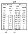
- FIG. 3 is an explanatory view showing terminal connection of the HC conversion cable and the receiving device in the present embodiment.
- the HC conversion cable receives the video signal output from the HDMI receptacle of the transmission device 10 by the HDMI plug 30 and outputs the video signal to the USB-C plug 32.
- the receiving device 20 determines the front and back of the USB-C plug 32 so that a suitable signal is input to the internal HDMI receiving unit Has a function of selecting a signal of
- the terminal connection of the HC conversion cable shown in FIG. 3 is a terminal connection in consideration of the case where the HC conversion cable is composed of a conversion dongle and a USB-C normal cable. For this reason, it differs from the terminal connection in the CH conversion cable in FIG. 2 (the connection destination of CLK + differs between B3 and A10 with reference to the dotted line frame 901 and the practice frame 902), but the details of this connection will be an example. This will be described in 3.
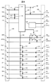
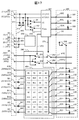
- FIG. 4 is a block diagram showing a configuration example of the HC conversion cable in the present embodiment.
- the input unit 120 is a terminal in the HDMI plug 30, and includes CEC, SCL, SDA, +5 V, HPD, Utility, CLK +, CLK ⁇ , D0 +, D0 ⁇ , D1 +, D1 ⁇ , D2 +, D2 ⁇ It is done.
- the output unit 160 is a terminal in the USB-C plug 32, and is composed of A5 and B5, A6, A7, A8, B8, A10, A11, B3, B2, B11, B10, A2 and A3. Under each terminal symbol, the respective signal names are described in italics in parentheses.
- 128 is a control unit
- 129 is a USB 2 functional unit
- 130 is a power supply terminal
- 121 and 122, 123, 124 are pull-up terminals such as resistors
- 126 and 127 are protective elements such as resistors
- 155 and 156 are switches
- 131 To 138 are termination elements such as resistors
- 161 to 168 are DC blocking elements such as capacitors.
- FIG. 5 is a block diagram showing a configuration example of the receiving apparatus in the present embodiment.
- an input unit 210 is a terminal in the USB-C receptacle of the receiving apparatus, and A5 and B5, A6, B6, A7, B7, A8, B8, A10, A11, B3, B2, B11, B10, A2 , A3.
- the input of the HDMI reception function unit 280 is configured of CEC and SCL, SDA, +5 V, HPD, Utility, CLK +, CLK-, D0 +, D0-, D1 +, D1-, D2 +, D2-.
- Reference numerals 211 and 212 denote pull-down elements such as resistors, 281, 282 and 283 denote pull-up elements such as resistors, 231 to 238 denote termination elements such as resistors, 255, 256 and 257 denote switches, and 258 denotes a termination power supply.
- 227 is a control unit
- 226 is a USB 2 function unit
- 263 and 264, 267, 268 are DC block elements such as capacitors.
- 241 to 248, 251, 252, 253, 254 are changeover switches.
- the control unit 227 of FIG. 5 is connected to the control unit 128 of FIG. 4 via the terminal A5 and the terminal B5 of the input unit 210, and the terminal A5 and the terminal B5 of the output unit 160 of FIG. Establish communication channels according to the procedures specified in the specification.
- the terminals A5 and B5 of the input unit 210 are pulled down to GND by 5.1 k ⁇ pull-down devices 211 and 212, and the A5 terminal of the output unit 160 is connected to the +5 V power supply terminal 130 by a 56 k ⁇ pull-up device 124 Therefore, the receiver shown in FIG. 5 is a sink that receives video signals, the input unit 210 is a UFP (Upstream facing Port), the relay device shown in FIG. 4 is a Source that outputs video signals, and the output unit 160 is a DFP (Downstream facing). Treated as Port).
- the B5 terminal of the output unit 160 is opened or pulled down in the control unit 128 until the output unit 160 is treated as DFP, so that the A5 terminal of the output unit 160 in FIG. 4 is 0.4 V and the B5 terminal is 0 V It becomes.
- the control unit 227 in FIG. 5 inserts a plug, and when 0.4 V is detected at the terminal B5, the plug is determined to be back-inserted.
- the switches 251 and 252 are switched according to the determination result 272. In the case of the face insertion determination, the upper side selection is shown, and in the case of the back insertion determination, the lower side selection is the reverse of the illustration.
- the DDC signal and the CEC signal transmitted by SCL and SDA are converted to the CC communication protocol of USB-C by the control unit 128, restored to the DDC signal and the CEC signal by the control unit 227, and transmitted to the HDMI reception function unit 280 Be
- the signal switching based on the front / back discrimination of the plug is switched in the state of the differential signal before the HDMI reception function unit 280, but may be switched after serial transmission decoding in the HDMI reception function unit 280.
- the signals are inverted (one's complement processing for parallel signals). Good.
- the terminal CEC of the input unit 120 is connected to the 3.3 V termination power supply 171 via the 27 k ⁇ pull-up element 121, and the terminals SCL and SDA are connected to the 5 V termination power supply 172 via the 47 k ⁇ pull up elements 122 and 123. Ru. These end power supplies 171 and 172 may supply power after the power is supplied to the terminal +5 V of the power supply terminal 130.
- DC block elements 161 to 168 are inserted in the HC conversion cable in FIG. 4 in accordance with the protection standard for USB-C data transmission that is premised on AC coupling. ing. Furthermore, termination elements 131 to 138 necessary for HDMI video signal transmission are connected to the termination power supply 139. Each termination element is, for example, a 50 ⁇ resistor, and the control unit 227 confirms the HDMI reception capability of the reception device 20 and, after confirming that +5 V is supplied from the transmission device 10, supplies 3.3 v to the termination power supply 139 .
- the terminals A8 and B8 of the output unit 160 transmitting the HPD and Utility signals are pulled down to GND by the protection elements 126 and 127 until the control unit 227 can confirm the HDMI reception capability to the receiving apparatus 20, and the USB-C element is Protect. After the control unit confirms the HDMI reception capability, the switches 155 and 156 are turned off according to the confirmation result 157, the pull-down is stopped, and the HPD and Utility signal transmission is performed.
- the HDMI reception function unit 280 in FIG. 5 is provided with 50 ⁇ termination elements 231 to 238 for impedance matching.
- the control unit 227 confirms from the information obtained at the terminal A5 or the terminal B5 of the input unit 210 that the relay apparatus has the transmission function of the HDMI video signal, and then between the 3.3 V termination power supply 258 and these termination elements By turning on the switch 257, the TMDS signals of CLK + and CLK-, D0 +, D0-, D1 +, D1-, D2 +, D2- can be received. Note that since the 50 ⁇ termination element 131 and the like in the HC conversion cable in FIG. 4 and the 50 ⁇ termination element 231 and the like in the HDMI reception function unit 280 in FIG.
- the termination impedance for the AC component is the HDMI transmitting apparatus.
- the signal amplitude is considered to be half that of a normal HDMI signal because it is apparently reduced to half as compared with the case where the HDMI receiving apparatus is connected with an HDMI cable without a 50 ⁇ termination. Therefore, the HDMI reception function unit 280 may have a reception sensitivity corresponding to half of a normal HDMI signal, or switch an input gain to have a double amplification function.
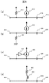
- FIG. 4 Another configuration example of the termination element 131 in the HC conversion cable of FIG. 4 is shown in FIG. These are configuration examples capable of suppressing a decrease in signal amplitude due to the impedance of the termination element.
- a constant current element 413 of 5 mA or less which is about half of 10 mA of the constant current source in the transmitter specified by HDMI, and a resistive element 412 of, for example, about 1 k ⁇ .
- constant current element 413 has a lower limit of 8 mA and a half of about 4 mA, and a difference of about 12 mA between the upper limit of 12 mA and the lower limit of 8 mA is about 2 mA from resistance element 412 Need to supply.
- the upper limit of the resistance element 412 is 350 ⁇ because the HDMI output specification permits a voltage drop of 700 mV. Since the resistance element 412 affects transmission impedance, a series inductance (not shown) may be inserted after setting the resistance element 412 to about 350 ⁇ .
- FIG. 6B shows an example in which a constant current element 423 of 5 mA or more, which is about half of the constant current source 10 mA in the transmission apparatus, is connected to a termination power supply, and a resistance element 422 of, for example, about 2 k ⁇ is connected to GND.
- the constant current element 423 is about half 6 mA of the upper limit 12 mA and about 2 mA which is half the difference 4 mA between the upper limit 12 mA and the lower limit 8 mA I need to pull it out.
- the resistance element 422 is about 1.3 k ⁇ as 2.6 V / 2 mA. Since the resistance element 422 affects transmission impedance, a series inductance (not shown) may be inserted after setting the resistance element 422 to about 1.3 k ⁇ .
- the resistance element may be provided with a series inductance in consideration of impedance matching.
- FIG. 6C shows that the current value of the constant current element 433 is subjected to feedback control by detecting an average voltage.
- the resistance elements are arranged in parallel to avoid voltage saturation. Instead, the current value is lowered when the average voltage becomes high, and the current value is raised when the average voltage becomes low,
- the average voltage range may be adjusted so that the voltage drop from the termination voltage is in the range of about 150 to 350 mV.
- FIG. 6D shows a termination element in which a resistance element 442 and an inductance 443 are connected in series.
- the resistive element 442 is 50 ⁇ and supplies 5 mA of DC current specified by HDMI.
- the AC component is interrupted by an inductance to prevent the amplitude degradation of the AC component.
- the HC conversion cable transmits the information to the receiver 20 through the CC communication channel.
- the receiving device 20 may determine whether to increase or decrease the reception sensitivity.
- the termination element 131 may be constructed on the side of the USB-C plug 32 with 100 ⁇ and notified to the receiving apparatus, and the termination element 231 of the receiving apparatus 20 may also be 100 ⁇ to secure the signal amplitude.
- the signal amplitude can be maintained while ensuring matching with the differential impedance 50 ⁇ of the cable portion.
- the power supply terminal 130 of the HC conversion cable in FIG. 4 may be supplied from an external power supply, or received as terminals A4 and B4, terminals A9 and B9 (not shown) from the receiver 20 to the output unit 160 as VBUS. Current may be used.
- power may be supplied to the receiver 20 as VBUS through the terminals A4 and B4, A9, and B9. USB-defined procedures can also be used for the use of VBUS.
- the control unit Is received by the receiver based on the information obtained from the sixth terminal.
- the protection element When it is determined that the seventh terminal has a predetermined voltage, the protection element is disconnected from the fourth terminal, a predetermined voltage is applied to the termination element, and the control unit When the standby state of the receiving apparatus is detected from the terminal, supply of the termination power to the termination element is started, and the video data is transmitted from the first terminal to the second terminal.
- an input unit (210) for video input from the relay apparatus a receiving function unit (280) for receiving and processing the input video, and a first terminal (A10, A11, etc.) of the input unit
- a first switch (241 to 248) for switching connection of the second terminal (CLK +, CLK-, etc.) of the reception function unit, a termination element (231 to 238) connected to the second terminal, and an input unit Second switch (253 to 256) for switching and opening / closing the third terminal (A8, B8) of the second terminal (HPD, Utility) of the reception function unit and the fifth terminal (A5) of the input unit , B5) and the control unit (227) to which the sixth terminal (CEC, SDL, SDA) of the reception function unit is connected, and the control unit is a relay apparatus based on the information obtained from the fifth terminal When it is determined that the device has a predetermined transmission function , Configured to apply a predetermined voltage to the terminating element.
- the transmission device has a determination function of determining mutual functions of the transmission device, the relay device, and the reception device.
- the function of the receiving device is determined to switch between the protection element provided at the input / output terminal and the termination element by enabling / disabling, the receiving device determines the function of the transmitting device and the relay device, and the front and back of the plug, The corresponding connection between the data input terminal and the reception function unit is switched, and the input gain of the reception function unit is switched.
- an HDMI video signal can be transmitted from the transmission device having the HDMI receptacle to the reception device having the USB receptacle using the HC conversion cable.
- FIG. 7 is a block diagram in which the transmitting device and the receiving device in the present embodiment are connected by a cable and a conversion dongle.
- an HR-CP conversion dongle 25 having a normal HDMI cable composed of HDMI plugs 36 and 38 and cable 37, an HDMI receptacle and a USB-C plug. To transmit the HDMI video signal from the transmission device 10 to the reception device 20.
- the HR-CP conversion dongle 25 can be realized with the same configuration as that of the HC conversion cable in FIG. 4 except that the plug 120 is changed from the plug to the receptacle.
- various types of transmission between the transmitter and the receiver can be performed using normal HDMI cables with various lengths and an HR-CP conversion dongle.
- the HDMI video signal can be transmitted according to the distance of.
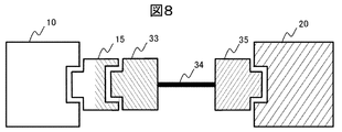
- FIG. 8 is a block diagram of connecting the transmitting device and the receiving device in the present embodiment by a conversion dongle and a cable.
- a normal HP-CR conversion dongle 15 having an HDMI plug and a USB-C receptacle, USB-C plugs 33 and 35, and a cable 34, instead of the HC conversion cable of FIG.
- the HDMI video signal is transmitted from the transmitting device 10 to the receiving device 20 using a USB-C cable.
- the HP-CR conversion dongle 15 can be realized with the same configuration except for the terminal arrangement except that the output section 160 of the HC conversion cable in FIG. 4 is changed from the plug terminal to the receptacle terminal. Since a normal USB-C cable has a so-called cross cable configuration in which transmission and reception terminals are interchanged, the connection between the terminals is different from that of the first embodiment.
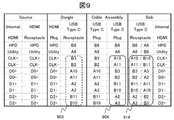
- FIG. 9 shows terminal connections in the present embodiment.
- the terminal arrangement of the HP-CR conversion dongle of FIG. 9 is matched to the CH conversion cable of FIG. 2 so that the C broken line frame 901 and the broken line frame 903 of FIG.
- the normal USB-C cable has the configuration in which the transmission terminal and the reception terminal are interchanged as described above, so the terminal arrangement of the USB-C plug on the receiver side is the same as that of FIG. 3 of the first embodiment. That is, the practice frame 902 of FIG. 3 and the practice frame 904 of FIG. 9 are in the same line.
- the receiving apparatus may have the same configuration as that of the first embodiment.
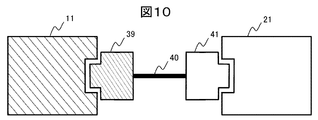
- FIG. 10 is a block diagram in which the transmitting device and the receiving device in the present embodiment are connected by a conversion cable.
- the transmitting device 11 having the USB-C receptacle and the receiving device 21 having the HDMI receptacle are connected by the C / H conversion cable configured of the USB-C plug 39, the cable 40, and the HDMI plug 41.
- the connection is similar to that of the conversion cable of Non-Patent Document 1, a function of reversing the connection direction of the conversion cable is added.
- This C / H conversion cable has a function of transmitting a video signal output from the USB-C receptacle of the transmitting apparatus shown in FIG. 10 to the HDMI receptacle of the receiving apparatus, and an output from the HDMI receptacle of the transmitting apparatus shown in FIG. It has the feature of being able to switch the function of transmitting the received video signal to the USB-C receptacle of the receiving device. That is, when the direction is reversed, it can also be used as the HC conversion cable described in the first embodiment.
- This two-way connection function has the advantage that it can be used without the user having to check which direction the conversion cable is compatible with.
- the terminal connection relationship is the same as the non-Patent Document 1 in the terminal connection of FIG.
- the terminal connection shown in FIG. 3 may be switched by determining the state to be used also as the HC conversion cable shown in FIG. 1 of the first embodiment.
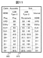
- FIG. 11 is an explanatory view showing terminal connections of the C / H conversion cable and the USB-C receptacle-equipped reception apparatus in the case where signal exchange in the conversion cable is not performed.
- the broken line frame 901 of FIG. 2 and the broken line frame 905 of FIG. 11 are arranged in the same manner.
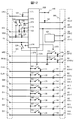
- FIG. 12 is a block diagram showing a configuration example of a C / H conversion cable in the present embodiment. Those having the same functions as those in FIG. 4 are given the same reference numerals.
- the terminal group 320 in the HDMI plug has CEC and SCL, SDA, +5 V, HPD, Utility, CLK +, CLK-, D0 +, D0-, D1 +, D1-, D2 +, and D2- terminals.
- the terminal group 360 in the USB plug has terminals A5, B5, A6, A7, B8, A8, B3, B2, A10, A11, A2, A3, B11, B10.
- 328 is a control unit
- 129 is a USB 2 function unit
- 130 is a power supply terminal
- 121 and 122, 123, 124 are pull-up terminals such as resistors
- 126 and 127 are protective elements such as resistors, 155 and 156, 181 to 188.
- switches, 131 to 138 are termination elements such as resistors, and 161 to 168 are DC blocking elements such as capacitors.
- the control unit 328 acquires connection destination information through the terminals A5 and B5, and determines whether the connection destination is an HDMI transmitting apparatus having a USB-C receptacle or an HDMI receiving apparatus. That is, in the case of the HDMI transmission apparatus, it is judged as the configuration of FIG. 10 and the terminal connection of FIG. 2 is made, and the video signal is transmitted from the terminal group 360 to the terminal group 320. If it is an HDMI receiving apparatus, it is judged as the configuration of FIG. 1 and the terminals are connected as shown in FIG.
- connection destination is an HDMI transmission device having a USB-C receptacle
- transmission may be damaged if the termination elements 131 to 138 are not removed, so termination power supply 375 and each termination may be used.
- Switches 181 to 188 may be provided between the elements 131 to 138, and each termination element may be opened at an instruction 374 of the control unit 328.
- connection destination is an HDMI transmitting device having a USB-C receptacle
- control is performed by providing a switch 324 for transmitting the +5 V power supplied to the B5 terminal of the terminal group 360 to the +5 V terminal of the terminal group 320.
- the current is transmitted at instruction 374 of the part 328.
- the switch 324 is opened.
- pull-up elements 122 and 123 of about 47 k ⁇ , pull-up elements 322 and 323 of about 1.9 k ⁇ , and switches 332 and 333 are arranged at the SCL and SDA terminals of the terminal group 320. If it is determined that the connection destination is an HDMI transmitting device having a USB-C receptacle, the switches 332 and 333 are closed by the instruction signal 373 of the control unit 328, and the pull-up resistors of SCL and SDA are 47 k ⁇ and 5.1 k ⁇ , respectively. Communication is performed with an HDMI receiver having an HDMI terminal with a parallel combined resistance value of approximately 1.8 k ⁇ .
- the control unit 328 performs SCL and SDA operations as an i2C master operation.
- connection destination is an HDMI receiving apparatus having a USB-C receptacle
- the SCL and SDA of the control unit 328 perform an i2C slave operation.
- the receiving apparatus may replace the terminal arrangement from the practice frame 912 of FIG. 3 to the dashed line frame 915 of FIG.
- the receiving device is based on the information acquisition result through the A5 terminal and the B5 terminal of USB-C, whether it is the HC conversion cable shown in FIG. 3 or the C / H conversion cable shown in FIG. A function of switching the terminal arrangement may be provided.
- the second transmission apparatus is connected to the terminal group (360) and the second reception apparatus is connected to the terminal group (320).
- the video data is detected and transmitted from the second terminal (A10, A3 etc.) to the first terminal (CLK +, D2 etc.).
- control unit (227) controls the first switch (241 to 248) based on the information obtained from the fifth terminal (A5, B5) of the connection state of the relay device. And switch the input gain of the reception function unit (280).
- the C / H conversion cable can be operated even using reverse connection, it is possible to save the trouble of confirming the transmission direction of the conversion cable, which is convenient for the user. Has the advantage of increasing
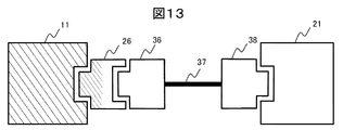
- FIG. 13 is a block diagram of connecting the transmitting device and the receiving device in the present embodiment by a conversion dongle and a cable.
- a normal HDMI cable composed of a CP / HR conversion dongle 26 having a USB-C plug and an HDMI receptacle, HDMI plugs 36 and 38, and a cable 37.
- the CP / HR conversion dongle 26 can be realized by the same configuration except that the terminal group 320 in the HDMI plug of the C / H conversion cable in FIG. 12 is changed from the plug to the receptacle.
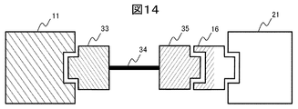
- FIG. 14 is a block diagram in which the transmitting device and the receiving device in this embodiment are connected by a cable and a conversion dongle.
- FIG. 14 instead of the C / H conversion cable of FIG. 10, a normal USB-C cable composed of USB-C plugs 33 and 35 and a cable 34, and a CR / H having a USB-C receptacle and an HDMI plug.
- the HDMI video signal is transmitted from the transmission device 11 to the reception device 21 using the HP conversion dongle 16.
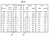
- FIG. 15 is a diagram for explaining terminal connection between the transmission device 11 and the CR / HP conversion dongle 16, the USB-C cable, and the reception device 21 in the configuration of FIG.
- the transmitting apparatus is the same as that in FIG. 2 but is cross-connected in the USB-C cable, and it becomes necessary to exchange them as indicated by the dashed frame 906 and the practical frame 907.
- the CR / HP conversion dongle 16 may change the terminal arrangement as shown in FIG. 15 in addition to changing the USB-C plug of the C / H conversion cable of FIG. 12 to a receptacle.
- the transmitter and the receiver are received using normal USB-C cables with various lengths and a CR / HP conversion dongle.
- the HDMI video signal can be transmitted according to various distances between the devices.
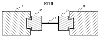
- FIG. 16 is a block diagram for connecting a transmitter and a receiver in the present embodiment by cable.
- the video transmission is performed from the transmitting device 11 having the USB-C receptacle to the receiving device 20 having the USB-C receptacle by the normal USB-C cable connecting the USB-C plugs 33 and 35 at both ends by the cable 34. It is something to do.
- the receiving device 20 corresponds to a combination of the CR / HP conversion dongle of the sixth embodiment and the HDMI receiving device.
- FIG. 17 shows a configuration example of a receiving apparatus which can cope with any of the connection configurations of FIG. 1, FIG. 7, FIG. 8 described in the first, second and third embodiments and FIG. .
- the input section 410 of the USB receptacle is composed of terminals A5 and B5, A6, B6, A7, B7, B8, A8, A10, A11, B3, B2, B11, B10, A2 and A3.
- the configuration of the HDMI reception function unit 280 is the same as that of FIG. 5, and the description with the same numbers will be omitted.
- 450 is a switching matrix.
- the control unit 427 of FIG. 17 is connected to the terminal A5 and the terminal B5 of the input unit 410 of the USB receptacle, and similarly to the control unit 227 of FIG. 5, the communication channel is established according to the procedure defined by the USB Type-C specification. I do. After establishing a communication channel, obtain the operating capability information of the transmitter with USB-C receptacle, conversion cable, conversion dongle, and USB-C cable, and grasp the configuration of Figure 1, Figure 7, Figure 8, and Figure 17, 3, FIG. 9, FIG. 11, and FIG. 15 determine which terminal connection is required, and control the conversion matrix 450.
- FIG. 3 HC conversion cable of FIG. 1, HR-CP conversion dongle of FIG. 7
- FIG. 9 HP-CR conversion dongle of FIG. It is preferable to switch # 1 and # 2 in the front / back judgment, and switch # 3 and # 4 in the front / back judgment of plug insertion if it is judged that the terminal connection of FIG. 11 (H / C conversion cable in FIG. 10) is necessary.
- the terminal arrangement is the same as in the CR / HP conversion dongle in FIG. 16 . Since the plug-in front / back determination is performed by the transmitter 11 with the USB-C receptacle, switching between the plug front / back in the USB-C receiver 20 is unnecessary. For the same reason, switching of the plug front and back by switches 253 and 254 is also unnecessary. However, it is necessary to switch the plug front and back by the switch 251 and the switch 252 based on the USB-C standard.
- the HDMI video signal can be transmitted from the USB-C transmission device to the USB-C reception device via the USB-C cable.
- HDMI video signal transmission can be performed via a USB-C cable between devices having a USB-C connector.
- the device having the USB-C connector and the HDMI reception function has an advantage of being able to operate even when various dongles are used in addition to the conversion cable and the USB-C cable.
Landscapes
- Engineering & Computer Science (AREA)
- Theoretical Computer Science (AREA)
- General Engineering & Computer Science (AREA)
- Multimedia (AREA)
- Signal Processing (AREA)
- Physics & Mathematics (AREA)
- General Physics & Mathematics (AREA)
- Computer Hardware Design (AREA)
- Computer Networks & Wireless Communication (AREA)
- Two-Way Televisions, Distribution Of Moving Picture Or The Like (AREA)
- Information Transfer Systems (AREA)
Priority Applications (2)
| Application Number | Priority Date | Filing Date | Title |
|---|---|---|---|
| CN201880064436.3A CN111164984B (zh) | 2017-10-06 | 2018-09-27 | 中继装置、接收装置以及使用它们的传输系统 |
| US16/652,683 US11503249B2 (en) | 2017-10-06 | 2018-09-27 | Relay device, receiving device, and transmission system using same |
Applications Claiming Priority (2)
| Application Number | Priority Date | Filing Date | Title |
|---|---|---|---|
| JP2017-196332 | 2017-10-06 | ||
| JP2017196332A JP6995557B2 (ja) | 2017-10-06 | 2017-10-06 | 中継装置、受信装置、及びそれらを用いた伝送システム |
Publications (1)
| Publication Number | Publication Date |
|---|---|
| WO2019069785A1 true WO2019069785A1 (ja) | 2019-04-11 |
Family
ID=65995142
Family Applications (1)
| Application Number | Title | Priority Date | Filing Date |
|---|---|---|---|
| PCT/JP2018/035926 Ceased WO2019069785A1 (ja) | 2017-10-06 | 2018-09-27 | 中継装置、受信装置、及びそれらを用いた伝送システム |
Country Status (4)
| Country | Link |
|---|---|
| US (1) | US11503249B2 (enExample) |
| JP (1) | JP6995557B2 (enExample) |
| CN (1) | CN111164984B (enExample) |
| WO (1) | WO2019069785A1 (enExample) |
Families Citing this family (3)
| Publication number | Priority date | Publication date | Assignee | Title |
|---|---|---|---|---|
| JP7437220B2 (ja) * | 2020-04-01 | 2024-02-22 | 株式会社東芝 | アダプタ装置及び通信方法 |
| TWI746083B (zh) * | 2020-07-24 | 2021-11-11 | 聯陽半導體股份有限公司 | 訊號中繼系統 |
| WO2022120385A1 (en) * | 2020-12-03 | 2022-06-09 | Sying, Inc. | Devices and methods for audio signal transmission from hdmi to usb-c |
Family Cites Families (15)
| Publication number | Priority date | Publication date | Assignee | Title |
|---|---|---|---|---|
| JP2011004215A (ja) * | 2009-06-19 | 2011-01-06 | Sony Corp | 信号供給システム、信号中継装置、電子機器、それらにおける方法およびプログラム |
| WO2011158310A1 (ja) * | 2010-06-15 | 2011-12-22 | パナソニック株式会社 | 通信装置 |
| TWM514025U (zh) | 2015-10-08 | 2015-12-11 | Sinbon Electronics Company Ltd | 具有微投影單元的可攜式擴展器 |
| US9990326B2 (en) * | 2015-10-14 | 2018-06-05 | Qualcomm Incorporated | Universal serial bus (USB) split cable |
| WO2017070941A1 (zh) * | 2015-10-30 | 2017-05-04 | 华为技术有限公司 | USB Type-C插头及线缆 |
| TWI593292B (zh) * | 2015-11-13 | 2017-07-21 | 晨星半導體股份有限公司 | 透過標準纜線傳送影音資訊的影音通訊裝置以及控制方法 |
| JP6661342B2 (ja) * | 2015-11-26 | 2020-03-11 | Dynabook株式会社 | ポート接続回路、ポート接続制御方法、電子機器 |
| CN105677611B (zh) | 2015-12-31 | 2020-02-07 | 北京小鸟看看科技有限公司 | 一种便携式设备以及控制hdmi信号输出的方法 |
| JP6840473B2 (ja) | 2016-06-24 | 2021-03-10 | 株式会社東芝 | アダプタ装置 |
| TWI615719B (zh) * | 2017-02-23 | 2018-02-21 | 宏正自動科技股份有限公司 | 自動切換裝置及自動切換方法 |
| CN107678985B (zh) * | 2017-09-06 | 2020-05-05 | 苏州佳世达光电有限公司 | 显示装置及讯号来源切换方法 |
| TWI653889B (zh) * | 2017-09-12 | 2019-03-11 | 宏正自動科技股份有限公司 | 視訊傳輸切換裝置 |
| US10317969B1 (en) * | 2018-04-27 | 2019-06-11 | Cypress Semiconductor Corporation | Dynamic VCONN swapping in dual-powered type-C cable applications |
| CN110275855B (zh) * | 2018-07-05 | 2023-09-05 | 威锋电子股份有限公司 | 信号传输方向调整方法与装置及双向信号中继器集成电路 |
| TWI700930B (zh) * | 2018-12-04 | 2020-08-01 | 宏正自動科技股份有限公司 | 切換裝置以及其影像切換系統與方法 |
-
2017
- 2017-10-06 JP JP2017196332A patent/JP6995557B2/ja active Active
-
2018
- 2018-09-27 WO PCT/JP2018/035926 patent/WO2019069785A1/ja not_active Ceased
- 2018-09-27 CN CN201880064436.3A patent/CN111164984B/zh active Active
- 2018-09-27 US US16/652,683 patent/US11503249B2/en active Active
Non-Patent Citations (2)
| Title |
|---|
| "Universal Serial Bus Type-C Cable and Connector Specification", USB, 14 July 2017 (2017-07-14), pages 1 - 6 , 14-27, 130-182, 203-210, Retrieved from the Internet <URL:https://usb.org/sites/default/files/documents/usb_type-c.zip> [retrieved on 20181016] * |
| SHENZHEN: "HDMI Over USB Type-C", LEGENDARY USB IMPLEMENTERS FORUM, 19 October 2016 (2016-10-19), pages 1 - 36, XP055589659, Retrieved from the Internet <URL:http://www.legendary.net.cn/html/downloads/HDMI_Alt_Mode_USB_Type-C.pdf> [retrieved on 20181016] * |
Also Published As
| Publication number | Publication date |
|---|---|
| US11503249B2 (en) | 2022-11-15 |
| CN111164984B (zh) | 2025-02-18 |
| JP2019071535A (ja) | 2019-05-09 |
| US20200244923A1 (en) | 2020-07-30 |
| JP6995557B2 (ja) | 2022-01-14 |
| CN111164984A (zh) | 2020-05-15 |
Similar Documents
| Publication | Publication Date | Title |
|---|---|---|
| JP5975360B2 (ja) | 汎用コネクタ及びハンドヘルド電子デバイス | |
| US8151018B2 (en) | Dual-mode data transfer of uncompressed multimedia contents or data communications | |
| KR101449229B1 (ko) | 액티브 케이블용 회로 | |
| CN107493462B (zh) | 视频处理设备 | |
| CN108509166B (zh) | 自动切换装置及自动切换方法 | |
| CN101925873A (zh) | 使用控制总线发现电子装置 | |
| US11094488B2 (en) | Port connection circuit, port connection control method and electronic device | |
| US20180011810A1 (en) | Multi-channel peripheral interconnect supporting simultaneous video and bus protocols | |
| WO2019069785A1 (ja) | 中継装置、受信装置、及びそれらを用いた伝送システム | |
| CN102201826B (zh) | 一种音频信号转接及接收装置,音频信号传输系统 | |
| WO2022012527A1 (zh) | 充电器、数据线、充电设备和电子设备 | |
| TWI511033B (zh) | 顯示系統及其操作最佳化之方法 | |
| JP6823729B2 (ja) | 映像機器および接続判定方法 | |
| CN108287289B (zh) | 共地检测电路及其检测方法 | |
| JP2020106876A (ja) | 通信インターフェース回路及びその制御方法 | |
| CN111277769B (zh) | 切换装置以及其影像切换系统与方法 | |
| CN114966134A (zh) | 一种全信号测试装置及方法 | |
| CN114609938A (zh) | 电子装置系统与电源传递方法 | |
| CN206313261U (zh) | 可扩展hdmi线 | |
| US12125457B2 (en) | Display Port (DP) sink device having main Phy circuit with plurality of DP connectors and plurality of AUX Phy circuits coupled to subsidiary link circuit | |
| CN216052679U (zh) | 一种hdmi连接线 | |
| CN108874704B (zh) | Usb接口电路及电子设备 | |
| KR20150016750A (ko) | Avn과 모바일의 인터페이스 장치 및 그 동작 방법 | |
| CN118054262A (zh) | 连接装置及其控制方法 | |
| CN118101873A (zh) | 一种hdmi接口电路 |
Legal Events
| Date | Code | Title | Description |
|---|---|---|---|
| 121 | Ep: the epo has been informed by wipo that ep was designated in this application |
Ref document number: 18863985 Country of ref document: EP Kind code of ref document: A1 |
|
| NENP | Non-entry into the national phase |
Ref country code: DE |
|
| 122 | Ep: pct application non-entry in european phase |
Ref document number: 18863985 Country of ref document: EP Kind code of ref document: A1 |
|
| WWG | Wipo information: grant in national office |
Ref document number: 201880064436.3 Country of ref document: CN |