WO2019065391A1 - Wheel loader and bucket carrying load calculation method - Google Patents
Wheel loader and bucket carrying load calculation method Download PDFInfo
- Publication number
- WO2019065391A1 WO2019065391A1 PCT/JP2018/034568 JP2018034568W WO2019065391A1 WO 2019065391 A1 WO2019065391 A1 WO 2019065391A1 JP 2018034568 W JP2018034568 W JP 2018034568W WO 2019065391 A1 WO2019065391 A1 WO 2019065391A1
- Authority
- WO
- WIPO (PCT)
- Prior art keywords
- bucket
- lift arm
- moment
- load
- wheel loader
- Prior art date
Links
Images


Classifications
-
- E—FIXED CONSTRUCTIONS
- E02—HYDRAULIC ENGINEERING; FOUNDATIONS; SOIL SHIFTING
- E02F—DREDGING; SOIL-SHIFTING
- E02F9/00—Component parts of dredgers or soil-shifting machines, not restricted to one of the kinds covered by groups E02F3/00 - E02F7/00
- E02F9/26—Indicating devices
- E02F9/264—Sensors and their calibration for indicating the position of the work tool
-
- E—FIXED CONSTRUCTIONS
- E02—HYDRAULIC ENGINEERING; FOUNDATIONS; SOIL SHIFTING
- E02F—DREDGING; SOIL-SHIFTING
- E02F9/00—Component parts of dredgers or soil-shifting machines, not restricted to one of the kinds covered by groups E02F3/00 - E02F7/00
- E02F9/26—Indicating devices
-
- E—FIXED CONSTRUCTIONS
- E02—HYDRAULIC ENGINEERING; FOUNDATIONS; SOIL SHIFTING
- E02F—DREDGING; SOIL-SHIFTING
- E02F3/00—Dredgers; Soil-shifting machines
- E02F3/04—Dredgers; Soil-shifting machines mechanically-driven
- E02F3/28—Dredgers; Soil-shifting machines mechanically-driven with digging tools mounted on a dipper- or bucket-arm, i.e. there is either one arm or a pair of arms, e.g. dippers, buckets
- E02F3/283—Dredgers; Soil-shifting machines mechanically-driven with digging tools mounted on a dipper- or bucket-arm, i.e. there is either one arm or a pair of arms, e.g. dippers, buckets with a single arm pivoted directly on the chassis
-
- G—PHYSICS
- G01—MEASURING; TESTING
- G01G—WEIGHING
- G01G19/00—Weighing apparatus or methods adapted for special purposes not provided for in the preceding groups
- G01G19/08—Weighing apparatus or methods adapted for special purposes not provided for in the preceding groups for incorporation in vehicles
- G01G19/10—Weighing apparatus or methods adapted for special purposes not provided for in the preceding groups for incorporation in vehicles having fluid weight-sensitive devices
-
- G—PHYSICS
- G01—MEASURING; TESTING
- G01G—WEIGHING
- G01G19/00—Weighing apparatus or methods adapted for special purposes not provided for in the preceding groups
- G01G19/14—Weighing apparatus or methods adapted for special purposes not provided for in the preceding groups for weighing suspended loads
- G01G19/16—Weighing apparatus or methods adapted for special purposes not provided for in the preceding groups for weighing suspended loads having fluid weight-sensitive devices
-
- G—PHYSICS
- G07—CHECKING-DEVICES
- G07C—TIME OR ATTENDANCE REGISTERS; REGISTERING OR INDICATING THE WORKING OF MACHINES; GENERATING RANDOM NUMBERS; VOTING OR LOTTERY APPARATUS; ARRANGEMENTS, SYSTEMS OR APPARATUS FOR CHECKING NOT PROVIDED FOR ELSEWHERE
- G07C5/00—Registering or indicating the working of vehicles
- G07C5/02—Registering or indicating driving, working, idle, or waiting time only
-
- G—PHYSICS
- G07—CHECKING-DEVICES
- G07C—TIME OR ATTENDANCE REGISTERS; REGISTERING OR INDICATING THE WORKING OF MACHINES; GENERATING RANDOM NUMBERS; VOTING OR LOTTERY APPARATUS; ARRANGEMENTS, SYSTEMS OR APPARATUS FOR CHECKING NOT PROVIDED FOR ELSEWHERE
- G07C5/00—Registering or indicating the working of vehicles
- G07C5/08—Registering or indicating performance data other than driving, working, idle, or waiting time, with or without registering driving, working, idle or waiting time
Definitions
- the present invention relates to the technical field of calculating the load acting on a bucket of a wheel loader.
- Patent Document 1 describes a method of calculating the load of a load such as iron scraps and scraps adsorbed on a front work device in a hydraulic excavator of a magnet specification. Specifically, “each moment in the no load state around the first and second pins is calculated from the weight of each joint angle and each movable member and the position of the center of gravity.
- Thrust calculated from the cylinder pressure around each pin The moment in the loaded condition around each pin is calculated from the boom angle and the bucket angle, and the difference between the moment in the loaded condition around the first pin and the moment in the no loading condition is the first The moment due to the load around the pin is calculated The moment due to the load around the second pin is calculated from the difference between the moment with the load around the second pin and the moment with no load. The lifting load is calculated by dividing by the horizontal distance from the first pin to the second pin.
- the working device of the hydraulic shovel includes a boom, a boom cylinder, an arm, an arm cylinder, a bucket, and a bucket cylinder.
- the front work apparatus of patent document 1 is the structure which attached the magnet instead of the bucket.
- the working device of the wheel loader includes a lift arm, a lift arm cylinder, a bucket, and a bucket cylinder, and the working device differs from the working device of the hydraulic shovel.
- the link mechanism for rotating the bucket is different between the hydraulic shovel and the wheel loader.
- Patent Document 1 discloses a load measurement method for a hydraulic shovel, but does not mention at all what it applies to a wheel loader.
- An object of the present invention is to provide a bucket loader load calculation method suitable for a wheel loader and a wheel loader that can accurately calculate the bucket load weight from the pressure of a lift arm cylinder.
- a vehicle body a lift arm provided at a front portion of the vehicle body and coupled to the vehicle body via a hinge pin, and pivoting the lift arm in the vertical direction
- a lift arm cylinder a bucket connected to the tip of the lift arm, and a working device including a bucket cylinder for rotating the bucket up and down, a lift arm angle sensor for detecting the angle of the lift arm, and the lift
- a wheel loader comprising a pressure sensor for detecting a pressure of an arm cylinder, a control device for calculating a load on the bucket, and a vehicle information database storing vehicle information including dimension data of the work device.
- the control device is configured such that the lift arm detected by the pressure sensor in an empty state of the bucket From the pressure of the cylinder, the angle of the lift arm detected by the lift arm angle sensor, and the dimension data extracted from the car body information database, an empty moment, which is a moment around the hinge pin, is calculated
- an empty moment which is a moment around the hinge pin
- the load moment which is the moment around the hinge pin, is calculated, and the difference between the empty load moment and the load moment is divided by the horizontal distance between the center of gravity of the bucket and the hinge pin to obtain the load of the bucket It is characterized by calculating.
- the loading load of the bucket can be accurately calculated from the pressure of the lift arm cylinder.
- the subject except having mentioned above, a structure, and an effect are clarified by description of the following embodiment.
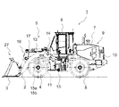
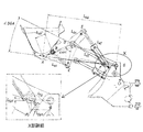
- FIG. 1 is a side view of a wheel loader 1 according to a first embodiment of the present invention.
- the wheel loader 1 comprises a front frame (vehicle body) 5 having a working device 27 and tires 4 and the like, and a rear frame (vehicle body) 9 having a cab 6, an engine compartment 7 and tires 8 and the like.
- Configured An engine (not shown) is mounted in the engine compartment 7, and a counterweight 10 is attached to the rear of the rear frame 9.
- the working device 27 includes a lift arm 2 connected to the front of the front frame 5 via a lift arm hinge pin G (see FIG. 4), a lift arm cylinder 11 for rotating the lift arm 2 in the vertical direction, and a lift arm A bucket 3 connected to the tip end of 2 and a bucket cylinder 12 for rotating the bucket 3 in the vertical direction are configured.
- the lift arm 2 is formed of a pair of left and right front and rear extending plate members
- the lift arm cylinder 11 is formed of a pair of left and right hydraulic cylinders.
- the lift arm 2 is pivoted (up and down) in the vertical direction by driving of the lift arm cylinder 11, and the bucket 3 is pivoted (cloud or dump) in the vertical direction by driving of the bucket cylinder 12.
- the front frame 5 and the rear frame 9 are rotatably connected to each other by a center pin 13, and the front frame 5 is refracted to the left and right with respect to the rear frame 9 by the expansion and contraction of a steering cylinder (not shown).
- a lift arm angle sensor 14 is attached to a connecting portion of the lift arm 2 and the front frame 5, and the pivot angle of the lift arm 2 is detected by the lift arm angle sensor 14.
- the lift arm cylinder 11 includes pressure sensors 15a and 15b. The bottom pressure of the lift arm cylinder 11 is detected by the pressure sensor 15a, and the rod pressure of the lift arm cylinder 11 is detected by the pressure sensor 15b.
- a link mechanism including a bell crank 16 and a push rod 23 is interposed between the bucket cylinder 12 and the bucket 3, and the bucket cylinder 12 rotates the bucket 3 via this link mechanism.
- the bucket cylinder 12 is provided with a bucket proximity switch 17, and when the rod of the bucket cylinder 12 is in the most contracted state, the bucket proximity switch 17 is turned on.
- the load W of the bucket 3 is calculated based on detection signals from the pressure sensors 15a and 15b, the bucket proximity switch 17, and the lift arm angle sensor 14. It has become.
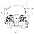
- FIG. 2 is a plan view showing the internal structure of the cab 6.
- the driver's seat 18 where the operator sits
- the steering wheel 19 for controlling the steering angle of the wheel loader 1
- the key switch 20 for starting / stopping the wheel loader 1
- a display device (monitor) 21 or the like that presents the information of Not only the engine speed and the vehicle speed of the wheel loader 1 are displayed on the display device 21, but also the loading load W of the bucket 3 calculated by the control device 30 described later is displayed.
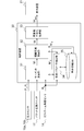
- the control device 30 that calculates the load W of the bucket 3 will be described.
- the control device 30 comprises, for example, a controller installed in the cab 6.
- the control device 30 calculates the loading weight W of the bucket 3 and executes various processes for displaying the loading weight W avg (average value) on the display device 21.
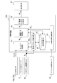
- FIG. 3 is a block diagram of the control device 30.
- the control device 30 includes a moment calculator 31, a load calculator 32, a load value averaging processor 33, a vehicle parameter extraction unit 34, and a vehicle information database (DB) 35. including.
- the various processes performed by the control device 30 are realized by loading a program stored in a storage device such as an HDD or the like into a memory by a CPU (not shown) and executing the program.
- the car body information database 35 is provided in the storage device.
- the moment calculation unit 31 receives the detection signal of the lift arm angle sensor 14, the detection signals of the pressure sensors 15a and 15b, the on / off signal of the bucket proximity switch 17, and the work device extracted by the vehicle body parameter extraction unit 34. 27 is input and the dimension data of, in the normal operation of the wheel loader 1, the moment M 1 about the lift arm hinge pin G in load state of the bucket 3 according to the operation equation to be described later (hereinafter, referred to as cargo moment M 1) for computing the. Further, at the time of initial operation of the wheel loader 1, the moment calculation unit 31 calculates a moment M 0 (hereinafter referred to as an empty moment M 0 ) around the lift arm hinge pin G in an empty state of the bucket 3. 0 is stored in the vehicle information database 35 as an initial learning value.
- a moment M 0 hereinafter referred to as an empty moment M 0
- the load calculation unit 32 calculates the loading moment M 1 calculated by the moment calculation unit 31, the dimension data of the work device 27 extracted by the vehicle body parameter extraction unit 34, and the initial learning value (empty moment M 0 ). Is input, and the load weight W of the bucket 3 is calculated according to an arithmetic expression described later.
- the load value averaging processing unit 33 receives the load W of the bucket 3 calculated by the load calculation unit 32, and performs a process of averaging the input values of the load W of the bucket 3. Then, the data of the averaged load load Wavg of the bucket 3 is output to the display device 21.
- the vehicle body parameter extraction unit 34 receives the detection signal from the lift arm angle sensor 14, extracts the dimension data of the working device 27 according to the lift arm angle ⁇ g (see FIG. 5) from the vehicle body information database 35, and It is output to the arithmetic unit 31.
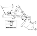
- 4 to 6 are calculation model diagrams for calculating the load W of the bucket 3.
- Equation (2) the relationship between the load load W of the bucket 3, the horizontal length L W between the lift arm hinge pin G and the center of gravity position of the load load W , the empty load moment M 0 and the load moment M 1 is from the balance of moments, Equation (2) below is obtained.
- the load W can be calculated by calculating the right side of the equation (2). It will be described later calculation method of horizontal length L W of the center of gravity of the live load W.
- a formula for calculating the moment M around the lift arm hinge pin G is derived from the bottom pressure and the rod pressure of the lift arm cylinder 11 measured by the pressure sensors 15a and 15b.
- the force F applied to the lift arm cylinder 11 can be calculated from the bottom pressure of the lift arm cylinder 11 and the rod pressure using the following equation (3).
- the force F b applied to the bucket cylinder 12 can be set as the following equation (4) from the balance equation of moments.
- the loading moment M 1 can be calculated by the following equation (5).
- W is 0 when the bucket 3 is in the empty state
- the influence on the bucket cylinder 12 is not considered when calculating the empty moment M 0 .
- P b represents the bottom pressure of the lift arm cylinder 11 detected by the pressure sensor 15 a
- P r represents the rod pressure of the lift arm cylinder 11 detected by the pressure sensor 15 b
- a, b In c, d, e, f, and L W , values of distances between links obtained from dimension data (constant data) stored in advance in the vehicle information database 35, and M 0 indicate the vehicle body at the time of initial operation of the wheel loader 1
- the values of empty moments stored in the information database 35 as initial learning values are substituted.
- the value of the denominator of equation (6) which is a variable, is a table previously associated with the value of lift arm angle sensor 14 (lift arm angle ⁇ g ). It is stored in the vehicle information database 35 as data. Therefore, if sensor data from pressure sensors 15a and 15b and lift arm angle sensor 14 are input, control device 30 can calculate the load W of bucket 3 according to equation (6).
- the inter-link distances a, b, c, d, e, f, and L W are variables depending on the lift arm angle ⁇ g and can be calculated using a trigonometric function.
- the calculation method of each link distance will be described.
- Table 1 the definitions of variables and constants used in the following equation are shown in Table 1.
- the constants shown in Table 1 are stored in advance in the vehicle information database 35.
- variables shown in Table 1 is a value that varies with the lift arm angle theta g, obtained by the following equation.
- inter-link distances L df and L af are determined by the cosine theorem, respectively, as in equations (15) and (16).
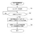
- FIG. 7 is a flowchart showing the procedure of the initial learning calculation process. The process shown in FIG. 7 is executed, for example, only when the control device 30 is set to the initial learning setting mode at the time of shipment of the wheel loader 1, and when the key switch 20 for starting / stopping the wheel loader 1 is turned on. Processing is started.
- the setting change to the initial learning setting mode can be performed, for example, by the operator outputting a mode change command from the dedicated terminal device to the control device 30.
- the moment calculation unit 31 acquires sensor data from the pressure sensors 15a and 15b and the lift arm angle sensor 14 (S1).
- the moment calculation unit 31 determines that the bucket 3 is in a posture in which the load such as earth and sand can be loaded, and the vehicle parameter extraction unit 34 It requests the extraction of the dimensional data of the device 27.
- Body parameter extraction unit 34 based on the lift arm angle theta g from the lift arm angle sensor 14, and extracts the size data corresponding to the lift arm angle theta g from the vehicle information database 35, outputs to the moment calculating unit 31 Do.
- the moment calculation unit 31 calculates an empty moment M 0 based on the input sensor data and dimension data (S 3). Then, the moment calculation unit 31 stores the empty load moment M 0 in the vehicle information database 35 as an initial learning value (S 4).
- the process waits in step S2 until the on signal is input.
- FIG. 8 is a flowchart showing the procedure of the load calculation process.
- the process shown in FIG. 8 is started when the key switch 20 for starting and stopping the wheel loader 1 is turned on during normal operation, and the processes of steps S1 to S4 are repeatedly executed in a predetermined cycle (for example, every several seconds). Ru.
- the moment calculator 31 acquires sensor data from the pressure sensors 15a and 15b and the lift arm angle sensor 14 (S11).
- the moment calculation unit 31 determines that the bucket 3 is in the posture in which the load such as earth and sand can be loaded, and the vehicle parameter extraction unit 34 It requests the extraction of the dimensional data of the device 27.
- Body parameter extraction unit 34 based on the lift arm angle theta g from the lift arm angle sensor 14, and extracts the size data corresponding to the lift arm angle theta g from the vehicle information database 35, outputs to the moment calculating unit 31 Do.
- the input sensor data on the basis of the dimension data, and calculates the load moment M 1, and outputs a load torque M 1 in the live load calculation unit 32 (S13).
- the load calculation unit 32 acquires dimension data stored in the vehicle information database 35 via the vehicle parameter extraction unit 34, and further acquires an empty moment M 0 from the vehicle information database 35. Then, the load calculation unit 32 calculates the load W of the bucket 3 from the difference between the load moment M 1 and the empty load moment M 0 using the above equation (6), and averages the load value W It outputs to the process part 33 (S14).
- the load value averaging processing unit 33 averages the loading weight W periodically input from the loading weight calculation unit 32 (S15), and outputs the averaged loading weight W avg to the display device 21 (S16). Thus, the load of the bucket 3 during the loading operation of the wheel loader 1 is displayed on the display device 21.
- the on signal is not input from the bucket proximity switch 17 (S12 / No), the process ends.
- the wheel loader 1 supporting the load of the bucket 3 by the lift arm cylinder 11 and the bucket cylinder 12 can use the above-described arithmetic expression to
- the loading load W of the bucket 3 can be calculated with high accuracy from the dimension data of the working device 27, the bottom pressure and the rod pressure of the lift arm cylinder 11, and the angle of the lift arm 2 without detecting the pressure.
- a sensor for detecting the pressure of the bucket cylinder 12 is not often provided, but in the present embodiment, it is not necessary to detect the pressure of the bucket cylinder 12, so the controller of the conventional wheel loader It is possible to easily calculate the load W of the bucket 3 simply by incorporating the load calculation program of the present invention.
- the loading load W of the bucket 3 can be calculated and displayed on the display device 21.
- a load such as a calibration weight
- initial learning was very time-consuming.
- the bucket is replaced at the site, the same initial learning is required again, but at the site, in many cases, it is not possible to prepare a heavy object such as a calibration weight, and the initial learning is difficult.
- the control device 30 automatically calculates the empty moment M 0 .
- a load such as a calibration weight. Therefore, even when the bucket 3 is replaced in the field, the bottom pressure and rod pressure of the lift arm cylinder 11 detected by the pressure sensors 15a and 15b only once at the initial operation after the bucket replacement and the lift arm angle and a lift arm angle theta g detected by the sensor 14, if calculating the unladen moment M 0 time, it calculates the loading weight W of the bucket 3 was replaced with high accuracy.
- the second embodiment is different from the first embodiment in the configuration of the control device. Therefore, the following description mainly demonstrates the difference between control devices, and the description of the same configuration as that of the first embodiment is omitted.
- FIG. 9 is a block diagram of a control device 130 according to the second embodiment.
- an engine rotational speed detection sensor 25 is provided to detect the rotational speed of the engine, and the value of the empty moment M 0 is calculated as the engine rotational speed.
- a plurality of points are stored in the vehicle information database 35 according to the second embodiment, unlike the first embodiment. Therefore, as the initial learning, the moment calculation unit 31 calculates a plurality of empty load moments M 0 corresponding to the engine rotational speed and stores the plurality of empty load moments M 0 in the vehicle information database 35.
- the loading load calculation unit 32 When calculating the loading load W of the bucket 3, the loading load calculation unit 32 causes the initial learning value selection unit 36 to extract an empty moment M 0 corresponding to the engine speed input from the engine speed sensor 24. To request. The output from the initial learning value selector 36, unladen moment M 0 stacking load calculating unit 32 using the corresponding to the engine speed for calculating the live load W.
- the second embodiment it is possible to use the unloaded moment M 0 corresponding to the engine speed, it is possible to more accurately calculating the live load W of the bucket 3 as compared with the first embodiment. More specifically, the bottom pressure and the rod pressure of the lift arm cylinder 11 detected by the pressure sensors 15a and 15b also change with the number of revolutions of the engine. Therefore, by storing a plurality of idle moments M 0 corresponding to the number of revolutions of the engine in the vehicle body information database 35, the load weight W of the bucket 3 is more accurately calculated in consideration of the number of revolutions of the engine. be able to.
Abstract
Provided is a wheel loader that can accurately calculate the carrying load of a bucket from the pressure of a lifting arm cylinder. A control device (30): calculates, with a bucket (3) being in an unloaded state, an unloaded moment (M0) around a hinge pin G from a lifting arm cylinder pressure detected by pressure sensors (15a, 15b), a lifting arm angle detected by a lifting arm angle sensor 14, and dimension data extracted from a vehicle body information database (35); calculates, with the bucket (3) being in a loaded state, a loaded moment (M1) around the hinge pin G from the lifting arm cylinder pressure, the lifting arm angle, and the dimension data extracted from the vehicle information database; and calculates a bucket carrying load (W) by dividing the difference between the unloaded moment and the loaded moment by the horizontal distance (LW) between the position of the center of gravity of the bucket and the hinge pin.
Description
本発明は、ホイールローダのバケットに作用する荷重を演算する技術分野に関する。
The present invention relates to the technical field of calculating the load acting on a bucket of a wheel loader.
本技術分野の背景技術として、例えば特許文献1には、マグネット仕様の油圧ショベルにおいて、フロント作業装置に吸着した鉄屑やスクラップ等の荷の荷重を演算する方法が記載されている。具体的には、「各関節角および各可動部材の重量および重心位置データから、第1、第2ピン回りの荷重無し状態での各モーメントを演算する。各ピン回りのシリンダ圧から演算した推力と、ブーム角およびバケット角とから、各ピン回りの荷重有り状態での各モーメントを演算する。第1ピン回りの荷重有り状態でのモーメントと荷重無し状態でのモーメントとの差より、第1ピン回りの荷重によるモーメントを演算する。第2ピン回りの荷重有り状態でのモーメントと荷重無し状態でのモーメントとの差より、第2ピン回りの荷重によるモーメントを演算する。各モーメントの差を、第1ピンから第2ピンまでの水平距離で割ることで吊上げ荷重を演算する。」という荷重測定方法が記載されている(要約参照)。
As a background art of the present technical field, for example, Patent Document 1 describes a method of calculating the load of a load such as iron scraps and scraps adsorbed on a front work device in a hydraulic excavator of a magnet specification. Specifically, “each moment in the no load state around the first and second pins is calculated from the weight of each joint angle and each movable member and the position of the center of gravity. Thrust calculated from the cylinder pressure around each pin The moment in the loaded condition around each pin is calculated from the boom angle and the bucket angle, and the difference between the moment in the loaded condition around the first pin and the moment in the no loading condition is the first The moment due to the load around the pin is calculated The moment due to the load around the second pin is calculated from the difference between the moment with the load around the second pin and the moment with no load. The lifting load is calculated by dividing by the horizontal distance from the first pin to the second pin.
油圧ショベルの作業装置は、ブームと、ブームシリンダと、アームと、アームシリンダと、バケットと、バケットシリンダと、を備えている。なお、特許文献1に記載のフロント作業装置は、バケットの代わりにマグネットを取り付けた構成である。一方、ホイールローダの作業装置は、リフトアームと、リフトアームシリンダと、バケットと、バケットシリンダと、を備えて構成されており、油圧ショベルの作業装置と構成要素が相違する。さらに、バケットを回動させるリンク機構が油圧ショベルとホイールローダとでは異なっている。
The working device of the hydraulic shovel includes a boom, a boom cylinder, an arm, an arm cylinder, a bucket, and a bucket cylinder. In addition, the front work apparatus of patent document 1 is the structure which attached the magnet instead of the bucket. On the other hand, the working device of the wheel loader includes a lift arm, a lift arm cylinder, a bucket, and a bucket cylinder, and the working device differs from the working device of the hydraulic shovel. Furthermore, the link mechanism for rotating the bucket is different between the hydraulic shovel and the wheel loader.
油圧ショベルでは、バケットに作用する荷重を最終的にブームシリンダで受けているため、ブームシリンダのシリンダ圧からバケットに作用する荷重を演算することができる。しかしながら、ホイールローダでは、バケットに作用する荷重を、リフトアームシリンダとバケットシリンダとで受けているため、油圧ショベルにおける荷重計測方法を、直ちにホイールローダに適用することはできない。特許文献1では、油圧ショベルについての荷重計測方法を開示しているが、ホイールローダに適用することについて何ら言及されていない。
In the hydraulic shovel, since the load acting on the bucket is finally received by the boom cylinder, the load acting on the bucket can be calculated from the cylinder pressure of the boom cylinder. However, in the wheel loader, since the load acting on the bucket is received by the lift arm cylinder and the bucket cylinder, the load measurement method in the hydraulic shovel can not be immediately applied to the wheel loader. Patent Document 1 discloses a load measurement method for a hydraulic shovel, but does not mention at all what it applies to a wheel loader.
本発明は、バケットの積載荷重をリフトアームシリンダの圧力から精度良く演算できるホイールローダおよびホイールローダに好適なバケット積載荷重演算方法を提供することを目的とする。
An object of the present invention is to provide a bucket loader load calculation method suitable for a wheel loader and a wheel loader that can accurately calculate the bucket load weight from the pressure of a lift arm cylinder.
上記の目的を達成するために、代表的な本発明は、車体と、前記車体の前部に設けられ、前記車体にヒンジピンを介して連結されるリフトアーム、前記リフトアームを上下方向に回動させるリフトアームシリンダ、前記リフトアームの先端に連結されるバケット、および前記バケットを上下方向に回動させるバケットシリンダを含む作業装置と、前記リフトアームの角度を検出するリフトアーム角度センサと、前記リフトアームシリンダの圧力を検出する圧力センサと、前記バケットの積載荷重を演算する制御装置と、前記作業装置の寸法データを含む車体情報が格納された車体情報データベースと、を備えたホイールローダにおいて、前記制御装置は、前記バケットの空荷状態において、前記圧力センサにて検出された前記リフトアームシリンダの圧力と、前記リフトアーム角度センサにて検出された前記リフトアームの角度と、前記車体情報データベースから抽出した前記寸法データとから、前記ヒンジピン周りのモーメントである空荷モーメントを演算し、前記バケットの積荷状態において、前記圧力センサにて検出された前記リフトアームシリンダの圧力と、前記リフトアーム角度センサにて検出された前記リフトアームの角度と、前記車体情報データベースから抽出した前記寸法データとから、前記ヒンジピン周りのモーメントである積荷モーメントを演算し、前記空荷モーメントと前記積荷モーメントとの差を前記バケットの重心位置と前記ヒンジピンとの水平距離で除算して、前記バケットの積載荷重を演算することを特徴とする。
In order to achieve the above object, according to a typical present invention, a vehicle body, a lift arm provided at a front portion of the vehicle body and coupled to the vehicle body via a hinge pin, and pivoting the lift arm in the vertical direction A lift arm cylinder, a bucket connected to the tip of the lift arm, and a working device including a bucket cylinder for rotating the bucket up and down, a lift arm angle sensor for detecting the angle of the lift arm, and the lift A wheel loader comprising a pressure sensor for detecting a pressure of an arm cylinder, a control device for calculating a load on the bucket, and a vehicle information database storing vehicle information including dimension data of the work device. The control device is configured such that the lift arm detected by the pressure sensor in an empty state of the bucket From the pressure of the cylinder, the angle of the lift arm detected by the lift arm angle sensor, and the dimension data extracted from the car body information database, an empty moment, which is a moment around the hinge pin, is calculated In the loading state of the bucket, the pressure of the lift arm cylinder detected by the pressure sensor, the angle of the lift arm detected by the lift arm angle sensor, and the dimension data extracted from the vehicle information database The load moment, which is the moment around the hinge pin, is calculated, and the difference between the empty load moment and the load moment is divided by the horizontal distance between the center of gravity of the bucket and the hinge pin to obtain the load of the bucket It is characterized by calculating.
本発明によれば、バケットの積載荷重をリフトアームシリンダの圧力から精度良く演算できる。なお、前述した以外の課題、構成、および効果は、以下の実施形態の説明により明らかにされる。
According to the present invention, the loading load of the bucket can be accurately calculated from the pressure of the lift arm cylinder. In addition, the subject except having mentioned above, a structure, and an effect are clarified by description of the following embodiment.
以下、本発明に係るホイールローダの実施形態について、図面を参照しつつ説明する。
Hereinafter, embodiments of a wheel loader according to the present invention will be described with reference to the drawings.
[第1実施形態]
図1は、本発明の第1実施形態に係るホイールローダ1の側面図である。図1に示すように、ホイールローダ1は、作業装置27、タイヤ4等を有する前フレーム(車体)5と、運転室6、エンジン室7、タイヤ8等を有する後フレーム(車体)9とで構成される。エンジン室7にはエンジン(不図示)が搭載されており、後フレーム9の後方にはカウンタウェイト10が取り付けられている。 First Embodiment
FIG. 1 is a side view of awheel loader 1 according to a first embodiment of the present invention. As shown in FIG. 1, the wheel loader 1 comprises a front frame (vehicle body) 5 having a working device 27 and tires 4 and the like, and a rear frame (vehicle body) 9 having a cab 6, an engine compartment 7 and tires 8 and the like. Configured An engine (not shown) is mounted in the engine compartment 7, and a counterweight 10 is attached to the rear of the rear frame 9.
図1は、本発明の第1実施形態に係るホイールローダ1の側面図である。図1に示すように、ホイールローダ1は、作業装置27、タイヤ4等を有する前フレーム(車体)5と、運転室6、エンジン室7、タイヤ8等を有する後フレーム(車体)9とで構成される。エンジン室7にはエンジン(不図示)が搭載されており、後フレーム9の後方にはカウンタウェイト10が取り付けられている。 First Embodiment
FIG. 1 is a side view of a
作業装置27は、前フレーム5の前部にリフトアームヒンジピンG(図4参照)を介して連結されるリフトアーム2と、リフトアーム2を上下方向に回動させるリフトアームシリンダ11と、リフトアーム2の先端に連結されるバケット3と、バケット3を上下方向に回動させるバケットシリンダ12とを含んで構成される。なお、リフトアーム2は左右一対の前後に延びる板材より構成され、リフトアームシリンダ11は、左右一対の2つの油圧シリンダにより構成されている。
The working device 27 includes a lift arm 2 connected to the front of the front frame 5 via a lift arm hinge pin G (see FIG. 4), a lift arm cylinder 11 for rotating the lift arm 2 in the vertical direction, and a lift arm A bucket 3 connected to the tip end of 2 and a bucket cylinder 12 for rotating the bucket 3 in the vertical direction are configured. The lift arm 2 is formed of a pair of left and right front and rear extending plate members, and the lift arm cylinder 11 is formed of a pair of left and right hydraulic cylinders.
リフトアーム2はリフトアームシリンダ11の駆動により上下方向に回動(俯仰動)し、バケット3はバケットシリンダ12の駆動により上下方向に回動(クラウドまたはダンプ)する。前フレーム5と後フレーム9とはセンタピン13により互いに回動自在に連結され、ステアリングシリンダ(不図示)の伸縮により後フレーム9に対し前フレーム5が左右に屈折する。
The lift arm 2 is pivoted (up and down) in the vertical direction by driving of the lift arm cylinder 11, and the bucket 3 is pivoted (cloud or dump) in the vertical direction by driving of the bucket cylinder 12. The front frame 5 and the rear frame 9 are rotatably connected to each other by a center pin 13, and the front frame 5 is refracted to the left and right with respect to the rear frame 9 by the expansion and contraction of a steering cylinder (not shown).
リフトアーム2と前フレーム5の連結部分にはリフトアーム角度センサ14が取り付けられており、このリフトアーム角度センサ14によってリフトアーム2の回動角度が検出される。リフトアームシリンダ11は圧力センサ15a,15bを備えており、圧力センサ15aによってリフトアームシリンダ11のボトム圧が検出され、圧力センサ15bによってリフトアームシリンダ11のロッド圧が検出される。バケットシリンダ12とバケット3の間にはベルクランク16、プッシュロッド23を含むリンク機構が介設されており、このリンク機構を介してバケットシリンダ12はバケット3を回動させる。バケットシリンダ12はバケット近接スイッチ17を備えており、バケットシリンダ12のロッドが最も収縮された状態になると、このバケット近接スイッチ17がオン動作するようになっている。
A lift arm angle sensor 14 is attached to a connecting portion of the lift arm 2 and the front frame 5, and the pivot angle of the lift arm 2 is detected by the lift arm angle sensor 14. The lift arm cylinder 11 includes pressure sensors 15a and 15b. The bottom pressure of the lift arm cylinder 11 is detected by the pressure sensor 15a, and the rod pressure of the lift arm cylinder 11 is detected by the pressure sensor 15b. A link mechanism including a bell crank 16 and a push rod 23 is interposed between the bucket cylinder 12 and the bucket 3, and the bucket cylinder 12 rotates the bucket 3 via this link mechanism. The bucket cylinder 12 is provided with a bucket proximity switch 17, and when the rod of the bucket cylinder 12 is in the most contracted state, the bucket proximity switch 17 is turned on.
なお、詳しくは後述するが、本実施形態では、圧力センサ15a,15b、バケット近接スイッチ17、およびリフトアーム角度センサ14からの検出信号に基づいて、バケット3の積載荷重Wが演算される構成となっている。
Although the details will be described later, in the present embodiment, the load W of the bucket 3 is calculated based on detection signals from the pressure sensors 15a and 15b, the bucket proximity switch 17, and the lift arm angle sensor 14. It has become.
図2は運転室6の内部構造を示す平面図である。図2に示すように、運転室6には、オペレータが座る運転席18と、ホイールローダ1の操舵角を制御するステアリングホイール19と、ホイールローダ1を始動・停止させるキースイッチ20と、オペレータへの情報を提示する表示装置(モニタ)21等が設置されている。表示装置21には、ホイールローダ1のエンジン回転数や車速が表示されるだけでなく、後述する制御装置30によって演算されるバケット3の積載荷重Wも表示される。
FIG. 2 is a plan view showing the internal structure of the cab 6. As shown in FIG. 2, the driver's seat 18 where the operator sits, the steering wheel 19 for controlling the steering angle of the wheel loader 1, the key switch 20 for starting / stopping the wheel loader 1, and the operator A display device (monitor) 21 or the like that presents the information of Not only the engine speed and the vehicle speed of the wheel loader 1 are displayed on the display device 21, but also the loading load W of the bucket 3 calculated by the control device 30 described later is displayed.
次に、バケット3の積載荷重Wを演算する制御装置30について説明する。制御装置30は、例えば運転室6内に設置されるコントローラから成る。制御装置30は、バケット3の積載荷重Wを演算し、表示装置21に積載荷重Wavg(平均値)を表示させるための各種処理を実行する。図3は制御装置30のブロック図である。図3に示すように、制御装置30は、モーメント演算部31と、積載荷重演算部32と、荷重値平均化処理部33と、車体パラメータ抽出部34と、車体情報データベース(DB)35と、を含む。制御装置30による各種処理は、HDD等の記憶装置などに記憶されたプログラムを、図示しないCPUがメモリにロードして実行することにより実現される。なお、車体情報データベース35は、記憶装置に設けられている。
Next, the control device 30 that calculates the load W of the bucket 3 will be described. The control device 30 comprises, for example, a controller installed in the cab 6. The control device 30 calculates the loading weight W of the bucket 3 and executes various processes for displaying the loading weight W avg (average value) on the display device 21. FIG. 3 is a block diagram of the control device 30. As shown in FIG. As shown in FIG. 3, the control device 30 includes a moment calculator 31, a load calculator 32, a load value averaging processor 33, a vehicle parameter extraction unit 34, and a vehicle information database (DB) 35. including. The various processes performed by the control device 30 are realized by loading a program stored in a storage device such as an HDD or the like into a memory by a CPU (not shown) and executing the program. The car body information database 35 is provided in the storage device.
モーメント演算部31には、リフトアーム角度センサ14の検出信号と、圧力センサ15a,15bの検出信号と、バケット近接スイッチ17のオン/オフ信号と、車体パラメータ抽出部34にて抽出された作業装置27の寸法データとが入力され、ホイールローダ1の通常運転時には、後述する演算式に従ってバケット3の積荷状態におけるリフトアームヒンジピンG周りのモーメントM1(以下、積荷モーメントM1という)を演算する。また、ホイールローダ1の初期運転時には、モーメント演算部31は、バケット3の空荷状態におけるリフトアームヒンジピンG周りのモーメントM0(以下、空荷モーメントM0という)を演算し、空荷モーメントM0を初期学習値として車体情報データベース35に記憶させる。
The moment calculation unit 31 receives the detection signal of the lift arm angle sensor 14, the detection signals of the pressure sensors 15a and 15b, the on / off signal of the bucket proximity switch 17, and the work device extracted by the vehicle body parameter extraction unit 34. 27 is input and the dimension data of, in the normal operation of the wheel loader 1, the moment M 1 about the lift arm hinge pin G in load state of the bucket 3 according to the operation equation to be described later (hereinafter, referred to as cargo moment M 1) for computing the. Further, at the time of initial operation of the wheel loader 1, the moment calculation unit 31 calculates a moment M 0 (hereinafter referred to as an empty moment M 0 ) around the lift arm hinge pin G in an empty state of the bucket 3. 0 is stored in the vehicle information database 35 as an initial learning value.
積載荷重演算部32には、モーメント演算部31にて演算された積荷モーメントM1と、車体パラメータ抽出部34にて抽出された作業装置27の寸法データおよび初期学習値(空荷モーメントM0)が入力され、後述する演算式に従ってバケット3の積載荷重Wを演算する。
The load calculation unit 32 calculates the loading moment M 1 calculated by the moment calculation unit 31, the dimension data of the work device 27 extracted by the vehicle body parameter extraction unit 34, and the initial learning value (empty moment M 0 ). Is input, and the load weight W of the bucket 3 is calculated according to an arithmetic expression described later.
荷重値平均化処理部33には、積載荷重演算部32により演算されたバケット3の積載荷重Wが入力され、入力されたバケット3の積載荷重Wの値を平均化する処理を行う。そして、平均化したバケット3の積載荷重Wavgのデータを表示装置21に出力する。
The load value averaging processing unit 33 receives the load W of the bucket 3 calculated by the load calculation unit 32, and performs a process of averaging the input values of the load W of the bucket 3. Then, the data of the averaged load load Wavg of the bucket 3 is output to the display device 21.
車体パラメータ抽出部34は、リフトアーム角度センサ14からの検出信号が入力され、リフトアーム角度θg(図5参照)に応じた作業装置27の寸法データを車体情報データベース35から抽出して、モーメント演算部31に出力する。
The vehicle body parameter extraction unit 34 receives the detection signal from the lift arm angle sensor 14, extracts the dimension data of the working device 27 according to the lift arm angle θ g (see FIG. 5) from the vehicle body information database 35, and It is output to the arithmetic unit 31.
車体情報データベース35には、バケット3の積載荷重Wを演算するために必要な作業装置27の各種寸法データや、空荷モーメントM0の値(初期学習値)等が記憶されている。
The vehicle information database 35, and various dimension data of the working device 27 required for calculating the live load W of the bucket 3, like the value of the tare moment M 0 (initial learning value) is stored.
次に、バケット3の積載荷重Wの演算方法について説明する。図4~図6は、バケット3の積載荷重Wを演算するための計算モデル図である。
Next, a method of calculating the load W of the bucket 3 will be described. 4 to 6 are calculation model diagrams for calculating the load W of the bucket 3.
(モーメントを用いた荷重演算式の概要と導出)
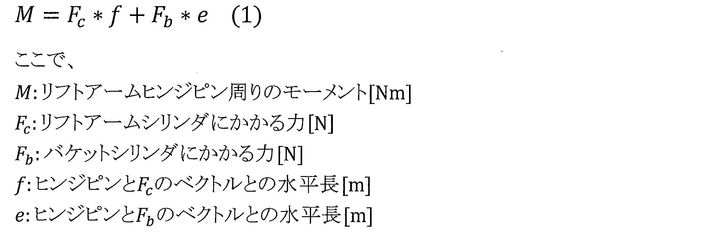
本実施形態で用いるバケット3の積載荷重Wの演算式を導出するためには、まずリフトアームヒンジピンG周りのモーメントMから、リフトアームシリンダ圧力と積載荷重Wの関係式が必要になる。そのために、まず各シリンダ11,12にかかる力とモーメントの関係を明確化する。リフトアームヒンジピンG周りのモーメントMは、図4のようにバケットシリンダ12とリフトアームシリンダ11に支えられており、その関係式は以下の式(1)となる。 (Outline and derivation of load calculation formula using moment)
In order to derive an arithmetic expression of the loading load W of thebucket 3 used in the present embodiment, first, from the moment M around the lift arm hinge pin G, a relational expression of the lift arm cylinder pressure and the loading load W is required. For that purpose, first, the relationship between the force applied to each of the cylinders 11 and 12 and the moment is clarified. The moment M around the lift arm hinge pin G is supported by the bucket cylinder 12 and the lift arm cylinder 11 as shown in FIG. 4, and the relational expression is given by the following equation (1).
本実施形態で用いるバケット3の積載荷重Wの演算式を導出するためには、まずリフトアームヒンジピンG周りのモーメントMから、リフトアームシリンダ圧力と積載荷重Wの関係式が必要になる。そのために、まず各シリンダ11,12にかかる力とモーメントの関係を明確化する。リフトアームヒンジピンG周りのモーメントMは、図4のようにバケットシリンダ12とリフトアームシリンダ11に支えられており、その関係式は以下の式(1)となる。 (Outline and derivation of load calculation formula using moment)
In order to derive an arithmetic expression of the loading load W of the
次に、バケット3の積載荷重W、リフトアームヒンジピンGと積載荷重Wの重心位置との間の水平長LW、空荷モーメントM0、積荷モーメントM1との関係は、モーメントの釣り合いから、以下の式(2)となる。
Next, the relationship between the load load W of the bucket 3, the horizontal length L W between the lift arm hinge pin G and the center of gravity position of the load load W , the empty load moment M 0 and the load moment M 1 is from the balance of moments, Equation (2) below is obtained.
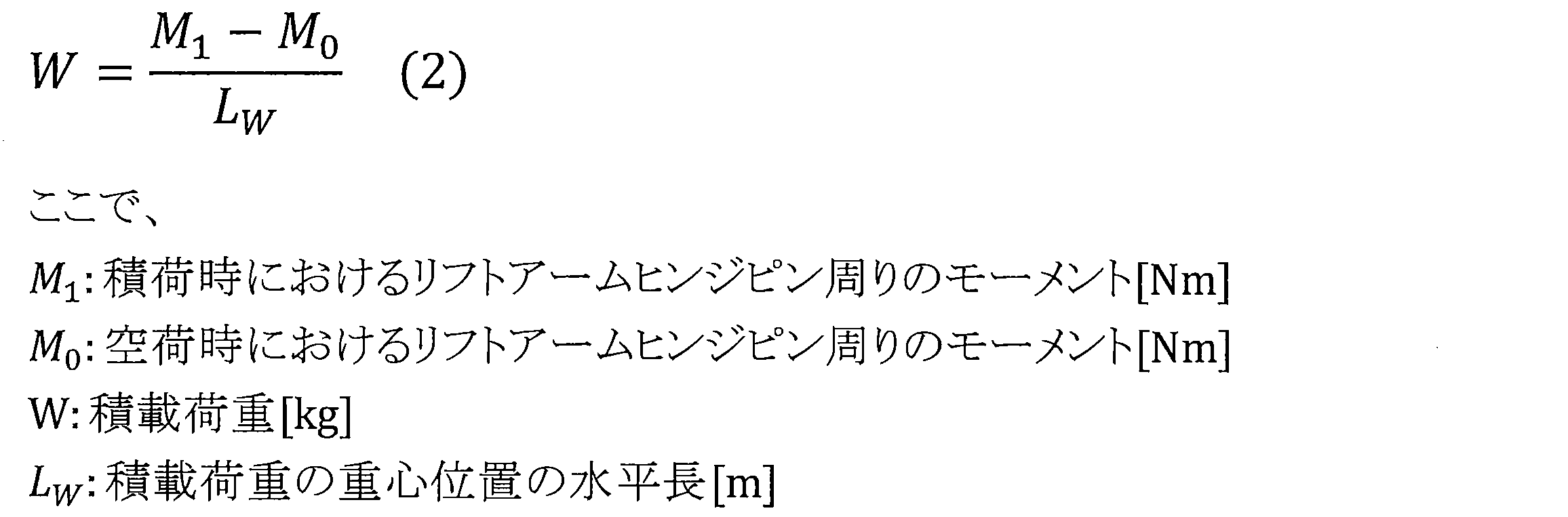
式(2)の右辺を計算することで、積載荷重Wを演算することができる。なお、積載荷重Wの重心位置の水平長LWの演算方法については後述する。
The load W can be calculated by calculating the right side of the equation (2). It will be described later calculation method of horizontal length L W of the center of gravity of the live load W.
(シリンダボトム圧を用いたモーメント演算式)
次に、圧力センサ15a,15bにより実測したリフトアームシリンダ11のボトム圧とロッド圧から、リフトアームヒンジピンG周りのモーメントMを演算する式を導出する。まず、リフトアームシリンダ11にかかる力Fは、リフトアームシリンダ11のボトム圧とロッド圧から以下の式(3)を用いて演算することができる。 (Moment calculation formula using cylinder bottom pressure)
Next, a formula for calculating the moment M around the lift arm hinge pin G is derived from the bottom pressure and the rod pressure of thelift arm cylinder 11 measured by the pressure sensors 15a and 15b. First, the force F applied to the lift arm cylinder 11 can be calculated from the bottom pressure of the lift arm cylinder 11 and the rod pressure using the following equation (3).
次に、圧力センサ15a,15bにより実測したリフトアームシリンダ11のボトム圧とロッド圧から、リフトアームヒンジピンG周りのモーメントMを演算する式を導出する。まず、リフトアームシリンダ11にかかる力Fは、リフトアームシリンダ11のボトム圧とロッド圧から以下の式(3)を用いて演算することができる。 (Moment calculation formula using cylinder bottom pressure)
Next, a formula for calculating the moment M around the lift arm hinge pin G is derived from the bottom pressure and the rod pressure of the

また、バケットシリンダ12にかかる力Fbは、モーメントの釣り合い式より、以下の式(4)と置くことができる。

Further, the force F b applied to the bucket cylinder 12 can be set as the following equation (4) from the balance equation of moments.
式(1)、式(3)、式(4)から、積荷モーメントM1は以下の式(5)により演算できる。なお、バケット3が空荷状態のときはW=0であるため、空荷モーメントM0を演算する際、バケットシリンダ12に対する影響は考えないものとする。

From the equation (1), the equation (3) and the equation (4), the loading moment M 1 can be calculated by the following equation (5). In addition, since W is 0 when the bucket 3 is in the empty state, the influence on the bucket cylinder 12 is not considered when calculating the empty moment M 0 .
(荷重演算式)
式(2)に式(5)を代入することで、リフトアームシリンダ圧と積載荷重Wの関係式を以下の式(6)のように導くことができる。この式(6)を解くことにより、バケット3の積載荷重Wを求めることができる。

(Load calculation formula)
By substituting the equation (5) into the equation (2), the relational equation between the lift arm cylinder pressure and the load W can be derived as the following equation (6). The loading load W of thebucket 3 can be obtained by solving the equation (6).
式(2)に式(5)を代入することで、リフトアームシリンダ圧と積載荷重Wの関係式を以下の式(6)のように導くことができる。この式(6)を解くことにより、バケット3の積載荷重Wを求めることができる。
By substituting the equation (5) into the equation (2), the relational equation between the lift arm cylinder pressure and the load W can be derived as the following equation (6). The loading load W of the
式(6)において、Pbには圧力センサ15aにて検出されたリフトアームシリンダ11のボトム圧、Prには圧力センサ15bにて検出されたリフトアームシリンダ11のロッド圧、a,b,c,d,e,f,LWには車体情報データベース35に予め記憶されている寸法データ(定数データ)から求めた各リンク間距離の値、M0にはホイールローダ1の初期運転時に車体情報データベース35に初期学習値として記憶された空荷モーメントの値が、それぞれ代入される。なお、本実施形態では、記憶装置の容量を削減するため、変数である式(6)の分母の値は、リフトアーム角度センサ14の値(リフトアーム角度θg)と予め対応付けられたテーブルデータとして車体情報データベース35に記憶されている。よって、制御装置30は、圧力センサ15a,15bとリフトアーム角度センサ14からのセンサデータが入力されれば、式(6)によりバケット3の積載荷重Wを演算することができる。
In equation (6), P b represents the bottom pressure of the lift arm cylinder 11 detected by the pressure sensor 15 a, P r represents the rod pressure of the lift arm cylinder 11 detected by the pressure sensor 15 b, a, b, In c, d, e, f, and L W , values of distances between links obtained from dimension data (constant data) stored in advance in the vehicle information database 35, and M 0 indicate the vehicle body at the time of initial operation of the wheel loader 1 The values of empty moments stored in the information database 35 as initial learning values are substituted. In the present embodiment, in order to reduce the capacity of the storage device, the value of the denominator of equation (6), which is a variable, is a table previously associated with the value of lift arm angle sensor 14 (lift arm angle θ g ). It is stored in the vehicle information database 35 as data. Therefore, if sensor data from pressure sensors 15a and 15b and lift arm angle sensor 14 are input, control device 30 can calculate the load W of bucket 3 according to equation (6).
ここで、各リンク間距離a,b,c,d,e,f,LWは、リフトアーム角度θgに依存する変数であり、三角関数を用いて演算することができる。以下、各リンク間距離の演算方法について説明する。
Here, the inter-link distances a, b, c, d, e, f, and L W are variables depending on the lift arm angle θ g and can be calculated using a trigonometric function. Hereinafter, the calculation method of each link distance will be described.
まず、以下の式に用いられる変数、定数の定義を表1に示す。表1に示す定数は、車体情報データベース35に予め記憶されている。一方、表1に示す変数は、リフトアーム角度θgによって変化する値であり、以下の式により求められる。
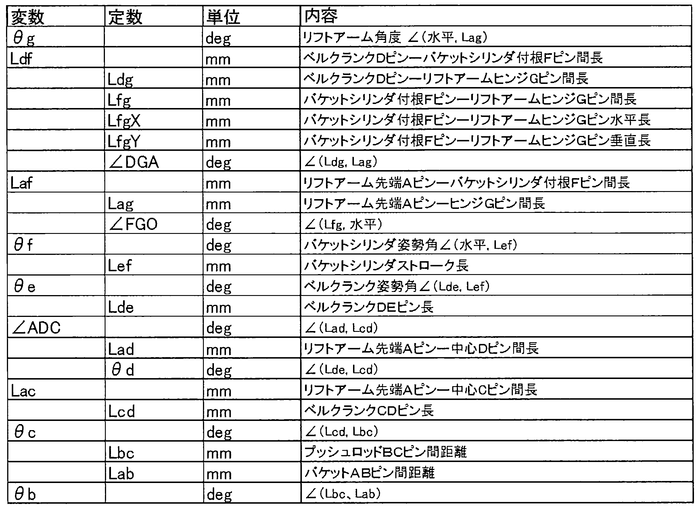
First, the definitions of variables and constants used in the following equation are shown in Table 1. The constants shown in Table 1 are stored in advance in the vehicle information database 35. Meanwhile, variables shown in Table 1 is a value that varies with the lift arm angle theta g, obtained by the following equation.
(リンク間距離の演算式)
各リンク間距離a,b,c,d,e,f,LWは、三角関数を用いて式(7)~式(13)により導かれる。 (Expression of distance between links)
The inter-link distances a, b, c, d, e, f, and L W are derived from equations (7) to (13) using trigonometric functions.
各リンク間距離a,b,c,d,e,f,LWは、三角関数を用いて式(7)~式(13)により導かれる。 (Expression of distance between links)
The inter-link distances a, b, c, d, e, f, and L W are derived from equations (7) to (13) using trigonometric functions.

ただし、θiは式(14)により求められる。

However, θ i can be obtained by equation (14).
(リンク姿勢角の演算式)
上記式(7)~(13)に用いられる各リンクの姿勢角(以下、リンク角という)θf,θe,θc,θbの演算方法について説明する。各リンク角は、車体情報データベース35に記憶されている作業装置27の寸法データ(定数)と、リフトアーム角度センサ14にて検出されたリフトアーム角度θgとに基づき、余弦定理を用いて幾何学的に演算できる。 (Calculation formula of link attitude angle)
A method of calculating the attitude angles θ f , θ e , θ c , and θ b of the links (hereinafter referred to as link angles) used in the equations (7) to (13) will be described. Each link angle, the size data of the workingdevice 27 stored in the body information database 35 (constant), based on the detected lift arm angle theta g at the lift arm angle sensor 14, using the cosine theorem geometric It can be calculated scientifically.
上記式(7)~(13)に用いられる各リンクの姿勢角(以下、リンク角という)θf,θe,θc,θbの演算方法について説明する。各リンク角は、車体情報データベース35に記憶されている作業装置27の寸法データ(定数)と、リフトアーム角度センサ14にて検出されたリフトアーム角度θgとに基づき、余弦定理を用いて幾何学的に演算できる。 (Calculation formula of link attitude angle)
A method of calculating the attitude angles θ f , θ e , θ c , and θ b of the links (hereinafter referred to as link angles) used in the equations (7) to (13) will be described. Each link angle, the size data of the working
リンク間距離LdfおよびLafは余弦定理により、それぞれ式(15)、式(16)のように決定される。

The inter-link distances L df and L af are determined by the cosine theorem, respectively, as in equations (15) and (16).
このとき、リンク角θfおよびθeは、それぞれ式(17)、式(18)のように導出される。
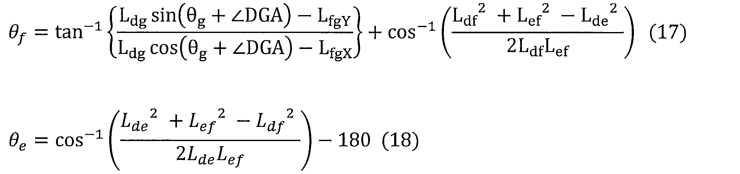
In this case, the link angle theta f and theta e are each formula (17) is derived as equation (18).
また、式(15)、式(16)で求めたリンク間距離LdfおよびLafによって、角度∠ADCおよび距離Lacが、それぞれ余弦定理により式(19)、式(20)のように決定される。
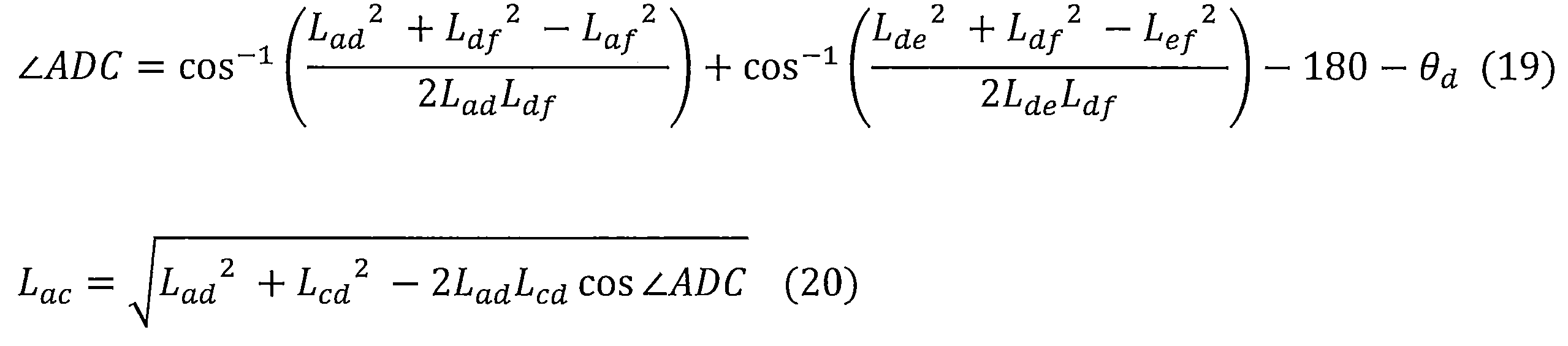
Further, by the inter-link distances L df and L af obtained by the equations (15) and (16), the angle ∠ ADC and the distance Lac are respectively determined by the cosine theorem as in the equations (19) and (20) Ru.
このとき、リンク角θcおよびθbは、それぞれ式(21)、式(22)のように導出される。
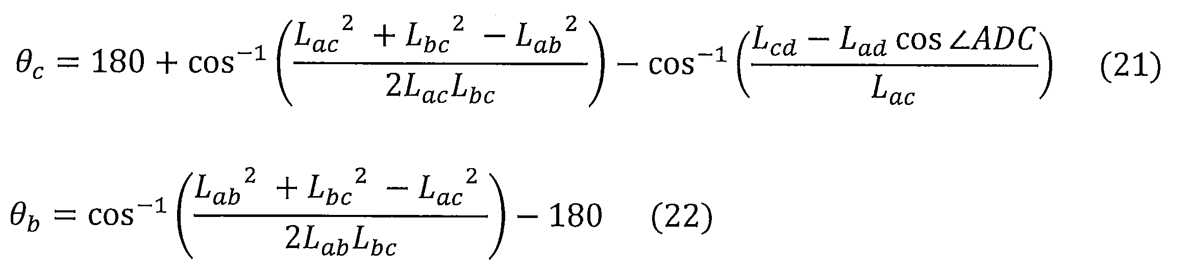
At this time, the link angles θ c and θ b are derived as shown in the equations (21) and (22), respectively.
式(15)~式(22)により求められた各変数を、式(7)~式(13)に代入することで、各リンク間距離a,b,c,d,e,f,LWは求まる。
By substituting the variables obtained by the equations (15) to (22) into the equations (7) to (13), the distances between the links a, b, c, d, e, f, L W are obtained. Is required.
次に、制御装置30により演算処理の手順について説明する。まず、ホイールローダ1の初期運転時に行う初期学習演算処理について説明する。図7は、初期学習演算処理の手順を示すフローチャートである。図7に示す処理は、例えばホイールローダ1の出荷時において制御装置30が初期学習設定モードに設定されている場合にのみ実行され、ホイールローダ1を始動・停止させるキースイッチ20がオンされると処理が開始される。なお、初期学習設定モードへの設定変更は、例えばオペレータが専用端末装置から制御装置30にモード変更指令を出力することにより可能である。
Next, the procedure of arithmetic processing by the control device 30 will be described. First, initial learning calculation processing performed at the time of initial operation of the wheel loader 1 will be described. FIG. 7 is a flowchart showing the procedure of the initial learning calculation process. The process shown in FIG. 7 is executed, for example, only when the control device 30 is set to the initial learning setting mode at the time of shipment of the wheel loader 1, and when the key switch 20 for starting / stopping the wheel loader 1 is turned on. Processing is started. The setting change to the initial learning setting mode can be performed, for example, by the operator outputting a mode change command from the dedicated terminal device to the control device 30.
図7に示すように、モーメント演算部31は、圧力センサ15a,15b、リフトアーム角度センサ14からセンサデータを取得する(S1)。モーメント演算部31は、バケット近接スイッチ17からオン信号が入力されると(S2/Yes)、バケット3が土砂等の積載物を積載可能な姿勢にあると判断し、車体パラメータ抽出部34に作業装置27の寸法データの抽出を要求する。車体パラメータ抽出部34は、リフトアーム角度センサ14からのリフトアーム角度θgに基づいて、車体情報データベース35の中からリフトアーム角度θgに対応する寸法データを抽出し、モーメント演算部31に出力する。モーメント演算部31は、入力されたセンサデータ、寸法データに基づき、空荷モーメントM0を演算する(S3)。そして、モーメント演算部31は、空荷モーメントM0を車体情報データベース35に初期学習値として記憶させる(S4)。なお、バケット近接スイッチ17からオン信号が入力されない場合(S2/No)、オン信号の入力があるまでステップS2で待機する。
As shown in FIG. 7, the moment calculation unit 31 acquires sensor data from the pressure sensors 15a and 15b and the lift arm angle sensor 14 (S1). When the on signal is input from the bucket proximity switch 17 (S2 / Yes), the moment calculation unit 31 determines that the bucket 3 is in a posture in which the load such as earth and sand can be loaded, and the vehicle parameter extraction unit 34 It requests the extraction of the dimensional data of the device 27. Body parameter extraction unit 34, based on the lift arm angle theta g from the lift arm angle sensor 14, and extracts the size data corresponding to the lift arm angle theta g from the vehicle information database 35, outputs to the moment calculating unit 31 Do. The moment calculation unit 31 calculates an empty moment M 0 based on the input sensor data and dimension data (S 3). Then, the moment calculation unit 31 stores the empty load moment M 0 in the vehicle information database 35 as an initial learning value (S 4). When the on signal is not input from the bucket proximity switch 17 (S2 / No), the process waits in step S2 until the on signal is input.
次に、バケット3の積載荷重Wの演算処理について説明する。図8は、積載荷重演算処理の手順を示すフローチャートである。図8に示す処理は、通常運転時において、ホイールローダ1を始動・停止させるキースイッチ20がオンされると開始され、所定の周期(例えば数秒毎)でステップS1~S4の処理が繰り返し実行される。
Next, calculation processing of the load W of the bucket 3 will be described. FIG. 8 is a flowchart showing the procedure of the load calculation process. The process shown in FIG. 8 is started when the key switch 20 for starting and stopping the wheel loader 1 is turned on during normal operation, and the processes of steps S1 to S4 are repeatedly executed in a predetermined cycle (for example, every several seconds). Ru.
図8に示すように、モーメント演算部31は、圧力センサ15a,15b、リフトアーム角度センサ14からセンサデータを取得する(S11)。モーメント演算部31は、バケット近接スイッチ17からオン信号が入力されると(S12/Yes)、バケット3が土砂等の積載物を積載可能な姿勢にあると判断し、車体パラメータ抽出部34に作業装置27の寸法データの抽出を要求する。車体パラメータ抽出部34は、リフトアーム角度センサ14からのリフトアーム角度θgに基づいて、車体情報データベース35の中からリフトアーム角度θgに対応する寸法データを抽出し、モーメント演算部31に出力する。モーメント演算部31は、入力されたセンサデータ、寸法データに基づき、積荷モーメントM1を演算し、積荷モーメントM1を積載荷重演算部32に出力する(S13)。
As shown in FIG. 8, the moment calculator 31 acquires sensor data from the pressure sensors 15a and 15b and the lift arm angle sensor 14 (S11). When the on signal is input from the bucket proximity switch 17 (S12 / Yes), the moment calculation unit 31 determines that the bucket 3 is in the posture in which the load such as earth and sand can be loaded, and the vehicle parameter extraction unit 34 It requests the extraction of the dimensional data of the device 27. Body parameter extraction unit 34, based on the lift arm angle theta g from the lift arm angle sensor 14, and extracts the size data corresponding to the lift arm angle theta g from the vehicle information database 35, outputs to the moment calculating unit 31 Do. Moment calculating unit 31, the input sensor data, on the basis of the dimension data, and calculates the load moment M 1, and outputs a load torque M 1 in the live load calculation unit 32 (S13).
積載荷重演算部32は、車体パラメータ抽出部34を介して車体情報データベース35に記憶されている寸法データを取得し、さらに、車体情報データベース35から空荷モーメントM0を取得する。そして、積載荷重演算部32は、上記式(6)を用いて、積荷モーメントM1と空荷モーメントM0との差からバケット3の積載荷重Wを演算し、積載荷重Wを荷重値平均化処理部33に出力する(S14)。
The load calculation unit 32 acquires dimension data stored in the vehicle information database 35 via the vehicle parameter extraction unit 34, and further acquires an empty moment M 0 from the vehicle information database 35. Then, the load calculation unit 32 calculates the load W of the bucket 3 from the difference between the load moment M 1 and the empty load moment M 0 using the above equation (6), and averages the load value W It outputs to the process part 33 (S14).
荷重値平均化処理部33は、積載荷重演算部32から周期的に入力される積載荷重Wを平均化し(S15)、平均化された積載荷重Wavgを表示装置21に出力する(S16)。こうして、ホイールローダ1の積込み作業中におけるバケット3の積載荷重が表示装置21に表示される。なお、バケット近接スイッチ17からオン信号が入力されない場合(S12/No)、処理は終了する。
The load value averaging processing unit 33 averages the loading weight W periodically input from the loading weight calculation unit 32 (S15), and outputs the averaged loading weight W avg to the display device 21 (S16). Thus, the load of the bucket 3 during the loading operation of the wheel loader 1 is displayed on the display device 21. When the on signal is not input from the bucket proximity switch 17 (S12 / No), the process ends.
以上説明したように、第1実施形態によれば、バケット3の荷重をリフトアームシリンダ11とバケットシリンダ12とにより支えるホイールローダ1に対して、上記した演算式を用いることで、バケットシリンダ12の圧力を検出することなく、作業装置27の寸法データと、リフトアームシリンダ11のボトム圧とロッド圧と、リフトアーム2の角度とからバケット3の積載荷重Wを高精度に演算することができる。
As described above, according to the first embodiment, the wheel loader 1 supporting the load of the bucket 3 by the lift arm cylinder 11 and the bucket cylinder 12 can use the above-described arithmetic expression to The loading load W of the bucket 3 can be calculated with high accuracy from the dimension data of the working device 27, the bottom pressure and the rod pressure of the lift arm cylinder 11, and the angle of the lift arm 2 without detecting the pressure.
また、従来のホイールローダでは、バケットシリンダ12の圧力を検出するセンサが設けられていないことが多いが、本実施形態ではバケットシリンダ12の圧力を検出する必要がないので、従来のホイールローダのコントローラに本発明の積載荷重演算プログラムを組み込むだけで、簡単にバケット3の積載荷重Wを演算することが可能である。
In addition, in the conventional wheel loader, a sensor for detecting the pressure of the bucket cylinder 12 is not often provided, but in the present embodiment, it is not necessary to detect the pressure of the bucket cylinder 12, so the controller of the conventional wheel loader It is possible to easily calculate the load W of the bucket 3 simply by incorporating the load calculation program of the present invention.
また、本実施形態では、ホイールローダ1の初期運転時に1度だけ空荷モーメントM0を求めておけば、バケット3の積載荷重Wを演算して表示装置21に表示させることができる。ちなみに、従来であれば、校正ウェイトなど重量が正確な積載物をバケットに積み、リフトアームシリンダの圧力とリフトアームの角度と積載物の重量との関係を初期学習させる必要があるが、この初期学習は積載物の重量を代えて何度も行う必要があった。そのため、初期学習が非常に手間であった。しかも、現場でバケットを交換した場合には、再度同様の初期学習が必要であるが、現場では校正ウェイトなどの重量物を準備できない場合が殆どで、初期学習が困難であった。
Further, in the present embodiment, when the empty moment M 0 is obtained only once at the time of initial operation of the wheel loader 1, the loading load W of the bucket 3 can be calculated and displayed on the display device 21. By the way, conventionally, it is necessary to load a load such as a calibration weight with an accurate weight on a bucket, and initially learn the relationship between the pressure of the lift arm cylinder and the angle of the lift arm and the weight of the load. Learning had to be done many times, changing the weight of the load. Therefore, initial learning was very time-consuming. Moreover, when the bucket is replaced at the site, the same initial learning is required again, but at the site, in many cases, it is not possible to prepare a heavy object such as a calibration weight, and the initial learning is difficult.
これに対して、第1実施形態に係るホイールローダ1では、リフトアーム2を上げて、バケット3をクラウド姿勢に保持すれば、制御装置30が自動的に空荷モーメントM0を演算するので、そもそも校正ウェイト等の積載物を用いて初期学習する必要はない。よって、バケット3を現場で交換した場合であっても、バケット交換後の初期運転時に1度だけ、圧力センサ15a,15bにより検出されるリフトアームシリンダ11のボトム圧およびロッド圧と、リフトアーム角度センサ14により検出されるリフトアーム角度θgとから、空荷モーメントM0を一度演算しておけば、交換したバケット3の積載荷重Wを高精度に演算できる。
On the other hand, in the wheel loader 1 according to the first embodiment, when the lift arm 2 is raised and the bucket 3 is held in the cloud attitude, the control device 30 automatically calculates the empty moment M 0 . In the first place, it is not necessary to initially learn using a load such as a calibration weight. Therefore, even when the bucket 3 is replaced in the field, the bottom pressure and rod pressure of the lift arm cylinder 11 detected by the pressure sensors 15a and 15b only once at the initial operation after the bucket replacement and the lift arm angle and a lift arm angle theta g detected by the sensor 14, if calculating the unladen moment M 0 time, it calculates the loading weight W of the bucket 3 was replaced with high accuracy.
[第2実施形態]
次に、本発明の第2実施形態に係るホイールローダについて説明する。第2実施形態は第1実施形態と制御装置の構成が相違する。よって、以下の説明は、主に制御装置の相違点を説明し、第1実施形態と同一の構成についての説明は省略する。 Second Embodiment
Next, a wheel loader according to a second embodiment of the present invention will be described. The second embodiment is different from the first embodiment in the configuration of the control device. Therefore, the following description mainly demonstrates the difference between control devices, and the description of the same configuration as that of the first embodiment is omitted.
図9は第2実施形態に係る制御装置130のブロック図である。図9に示すように、第2実施形態に係るホイールローダでは、エンジンの回転数を検出するために、エンジン回転数検出センサ25が設けられており、空荷モーメントM0の値をエンジン回転数に応じて複数、車体情報データベース35に格納している点が第1実施形態と相違する。そのため、モーメント演算部31は、初期学習として、エンジン回転数に応じた複数の空荷モーメントM0を演算して車体情報データベース35に記憶させる。積載荷重演算部32は、バケット3の積載荷重Wを演算する際に、エンジン回転数センサ24から入力されるエンジン回転数に応じた空荷モーメントM0を抽出するよう初期学習値選択部36に要求する。そして、初期学習値選択部36から出力された、エンジン回転数に対応する空荷モーメントM0を用いて積載荷重演算部32が積載荷重Wを演算する。
FIG. 9 is a block diagram of a control device 130 according to the second embodiment. As shown in FIG. 9, in the wheel loader according to the second embodiment, an engine rotational speed detection sensor 25 is provided to detect the rotational speed of the engine, and the value of the empty moment M 0 is calculated as the engine rotational speed. A plurality of points are stored in the vehicle information database 35 according to the second embodiment, unlike the first embodiment. Therefore, as the initial learning, the moment calculation unit 31 calculates a plurality of empty load moments M 0 corresponding to the engine rotational speed and stores the plurality of empty load moments M 0 in the vehicle information database 35. When calculating the loading load W of the bucket 3, the loading load calculation unit 32 causes the initial learning value selection unit 36 to extract an empty moment M 0 corresponding to the engine speed input from the engine speed sensor 24. To request. The output from the initial learning value selector 36, unladen moment M 0 stacking load calculating unit 32 using the corresponding to the engine speed for calculating the live load W.
この第2実施形態によれば、エンジン回転数に対応する空荷モーメントM0を用いることができるため、バケット3の積載荷重Wを第1実施形態と比べてより精度良く演算することができる。より詳細に説明すると、圧力センサ15a,15bによって検出されるリフトアームシリンダ11のボトム圧、ロッド圧は、エンジンの回転数によっても変化する。そのため、エンジンの回転数に応じた空荷モーメントM0を複数、車体情報データベース35に格納しておくことで、エンジンの回転数を考慮して、より正確にバケット3の積載荷重Wを演算することができる。
According to the second embodiment, it is possible to use the unloaded moment M 0 corresponding to the engine speed, it is possible to more accurately calculating the live load W of the bucket 3 as compared with the first embodiment. More specifically, the bottom pressure and the rod pressure of the lift arm cylinder 11 detected by the pressure sensors 15a and 15b also change with the number of revolutions of the engine. Therefore, by storing a plurality of idle moments M 0 corresponding to the number of revolutions of the engine in the vehicle body information database 35, the load weight W of the bucket 3 is more accurately calculated in consideration of the number of revolutions of the engine. be able to.
なお、上記した実施形態は、本発明の説明のための例示であり、本発明の範囲をそれらの実施形態にのみ限定する趣旨ではない。当業者は、本発明の要旨を逸脱することなしに、他の様々な態様で本発明を実施することができる。
In addition, the above-mentioned embodiment is an illustration for description of this invention, and it is not the meaning which limits the scope of the present invention only to those embodiments. Those skilled in the art can practice the present invention in various other aspects without departing from the scope of the present invention.
1 ホイールローダ
2 リフトアーム
3 バケット
5 前フレーム(車体)
9 後フレーム(車体)
11 リフトアームシリンダ
12 バケットシリンダ
14 リフトアーム角度センサ
15a,15b 圧力センサ
16 ベルクランク
17 バケット近接スイッチ
21 表示装置
23 プッシュロッド
25 エンジン回転数センサ
30 制御装置
31 モーメント演算部
32 積載荷重演算部
33 荷重値平均化処理部
34 車体パラメータ抽出部
35 車体情報データベース(DB)
36 初期学習値選択部
130 制御装置 1wheel loader 2 lift arm 3 bucket 5 front frame (vehicle body)
9 Rear frame (vehicle body)
11lift arm cylinder 12 bucket cylinder 14 lift arm angle sensor 15a, 15b pressure sensor 16 bell crank 17 bucket proximity switch 21 display device 23 push rod 25 engine rotational speed sensor 30 control device 31 moment calculator 32 load value calculator 33 load value Averaging processing unit 34 Body parameter extraction unit 35 Body information database (DB)
36 Initial learningvalue selection unit 130 Controller
2 リフトアーム
3 バケット
5 前フレーム(車体)
9 後フレーム(車体)
11 リフトアームシリンダ
12 バケットシリンダ
14 リフトアーム角度センサ
15a,15b 圧力センサ
16 ベルクランク
17 バケット近接スイッチ
21 表示装置
23 プッシュロッド
25 エンジン回転数センサ
30 制御装置
31 モーメント演算部
32 積載荷重演算部
33 荷重値平均化処理部
34 車体パラメータ抽出部
35 車体情報データベース(DB)
36 初期学習値選択部
130 制御装置 1
9 Rear frame (vehicle body)
11
36 Initial learning
Claims (6)
- 車体と、前記車体の前部に設けられ、前記車体にヒンジピンを介して連結されるリフトアーム、前記リフトアームを上下方向に回動させるリフトアームシリンダ、前記リフトアームの先端に連結されるバケット、および前記バケットを上下方向に回動させるバケットシリンダを含む作業装置と、前記リフトアームの角度を検出するリフトアーム角度センサと、前記リフトアームシリンダの圧力を検出する圧力センサと、前記バケットの積載荷重を演算する制御装置と、前記作業装置の寸法データを含む車体情報が格納された車体情報データベースと、を備えたホイールローダにおいて、
前記制御装置は、
前記バケットの空荷状態において、前記圧力センサにて検出された前記リフトアームシリンダの圧力と、前記リフトアーム角度センサにて検出された前記リフトアームの角度と、前記車体情報データベースから抽出した前記寸法データとから、前記ヒンジピン周りのモーメントである空荷モーメントを演算し、
前記バケットの積荷状態において、前記圧力センサにて検出された前記リフトアームシリンダの圧力と、前記リフトアーム角度センサにて検出された前記リフトアームの角度と、前記車体情報データベースから抽出した前記寸法データとから、前記ヒンジピン周りのモーメントである積荷モーメントを演算し、
前記空荷モーメントと前記積荷モーメントとの差を前記バケットの重心位置と前記ヒンジピンとの水平距離で除算して、前記バケットの積載荷重を演算することを特徴とするホイールローダ。 A vehicle body, a lift arm provided at a front portion of the vehicle body and connected to the vehicle body via a hinge pin, a lift arm cylinder that vertically rotates the lift arm, a bucket connected to a tip of the lift arm; And a working device including a bucket cylinder for rotating the bucket in the vertical direction, a lift arm angle sensor for detecting an angle of the lift arm, a pressure sensor for detecting a pressure of the lift arm cylinder, and a load of the bucket A wheel loader comprising a control device for calculating the vehicle speed and a car body information database storing car body information including dimension data of the work device,
The controller is
In the empty state of the bucket, the pressure of the lift arm cylinder detected by the pressure sensor, the angle of the lift arm detected by the lift arm angle sensor, and the dimension extracted from the vehicle information database From the data, calculate the empty moment which is the moment around the hinge pin,
In the loading state of the bucket, the pressure of the lift arm cylinder detected by the pressure sensor, the angle of the lift arm detected by the lift arm angle sensor, and the dimension data extracted from the vehicle information database And calculate the loading moment which is the moment around the hinge pin from
A wheel loader characterized by calculating a loading load of the bucket by dividing a difference between the idle moment and the loading moment by a horizontal distance between a center of gravity position of the bucket and the hinge pin. - 請求項1に記載のホイールローダにおいて、
前記制御装置は、
前記ホイールローダの初期運転時に、前記空荷モーメントを演算して、前記車体情報データベースに記憶させ、
前記ホイールローダの通常運転時に前記バケットの積載荷重を演算する際には、前記車体情報データベースに記憶されている前記空荷モーメントと、前記圧力センサおよび前記リフトアーム角度センサからの実測データに基づき演算された前記積荷モーメントとから、前記バケットの積載荷重を演算することを特徴とするホイールローダ。 In the wheel loader according to claim 1,
The controller is
At the initial operation of the wheel loader, the empty load moment is calculated and stored in the vehicle information database.
When calculating the loading load of the bucket during normal operation of the wheel loader, calculation is performed based on the empty moment stored in the vehicle body information database and the measured data from the pressure sensor and the lift arm angle sensor A wheel loader, characterized in that the loading load of the bucket is calculated from the loaded load moment. - 請求項1に記載のホイールローダにおいて、
前記バケットシリンダのロッドが最も収縮された状態になるとオン動作するバケット近接スイッチをさらに備え、
前記制御装置は、前記バケット近接スイッチからのオン信号に基づき、前記空荷モーメントと前記積荷モーメントとを演算することを特徴とするホイールローダ。 In the wheel loader according to claim 1,
The apparatus further comprises a bucket proximity switch that is turned on when the rod of the bucket cylinder is in the most contracted state,
The wheel loader, wherein the control device calculates the unloading moment and the loading moment based on an on signal from the bucket proximity switch. - 請求項2に記載のホイールローダにおいて、
前記車体を走行駆動させるためのエンジンと、前記エンジンの回転数を検出するエンジン回転数センサと、をさらに備え、
前記制御装置は、
前記ホイールローダの初期運転時に前記エンジンの回転数に応じた前記空荷モーメントを複数演算し、前記車体情報データベースに前記空荷モーメントを前記エンジンの回転数と対応付けて記憶させ、
前記ホイールローダの通常運転時に前記バケットの積載荷重を演算する際には、前記エンジン回転数センサにて検出された前記エンジンの回転数に対応する前記空荷モーメントと、実測値に基づき演算された前記積荷モーメントとから、前記バケットの積載荷重を演算することを特徴とするホイールローダ。 In the wheel loader according to claim 2,
The engine further includes an engine for driving the vehicle and an engine rotational speed sensor for detecting the rotational speed of the engine.
The controller is
At the initial operation of the wheel loader, a plurality of empty moments according to the number of revolutions of the engine are calculated, and the empty moments are stored in the vehicle information database in association with the number of revolutions of the engine.
When calculating the loading load of the bucket during normal operation of the wheel loader, it is calculated based on the empty moment corresponding to the number of revolutions of the engine detected by the engine revolution number sensor and the actual value. A wheel loader, characterized in that the loading load of the bucket is calculated from the loading moment. - 請求項2に記載のホイールローダにおいて、
前記バケットシリンダのロッドが最も収縮された状態になるとオン動作するバケット近接スイッチをさらに備え、
前記制御装置は、前記バケット近接スイッチからのオン信号に基づき、前記空荷モーメントと前記積荷モーメントとを演算することを特徴とするホイールローダ。 In the wheel loader according to claim 2,
The apparatus further comprises a bucket proximity switch that is turned on when the rod of the bucket cylinder is in the most contracted state,
The wheel loader, wherein the control device calculates the unloading moment and the loading moment based on an on signal from the bucket proximity switch. - 車体と、前記車体の前部に設けられ、前記車体にヒンジピンを介して連結されるリフトアーム、前記リフトアームを上下方向に回動させるリフトアームシリンダ、前記リフトアームの先端に連結されるバケット、および前記バケットを上下方向に回動させるバケットシリンダを含む作業装置と、前記リフトアームの角度を検出するリフトアーム角度センサと、前記リフトアームシリンダの圧力を検出する圧力センサと、前記作業装置の寸法データを含む各種の車体情報が格納された車体情報データベースと、を備えたホイールローダに使用され、前記バケットの積載荷重を演算するバケット積載荷重演算方法であって、
前記バケットの空荷状態において、前記圧力センサにて検出された前記リフトアームシリンダの圧力と、前記リフトアーム角度センサにて検出された前記リフトアームの角度と、前記車体情報データベースから抽出した前記寸法データとから、前記ヒンジピン周りのモーメントである空荷モーメントを演算し、前記空荷モーメントを初期学習値として前記車体情報データベースに記憶させる第1手順と、
前記バケットの積荷状態において、前記圧力センサにて検出された前記リフトアームシリンダの圧力と、前記リフトアーム角度センサにて検出された前記リフトアームの角度と、前記車体情報データベースから抽出した前記寸法データとから、前記ヒンジピン周りのモーメントである積荷モーメントを演算する第2手順と、
前記第1手順により前記車体情報データベースに記憶された前記空荷モーメントと、前記第2手順により演算された前記積荷モーメントとの差を前記バケットの重心位置と前記ヒンジピンとの水平距離で除算して、前記バケットの積載荷重を演算する第3手順を含むことを特徴とするバケット積載荷重演算方法。 A vehicle body, a lift arm provided at a front portion of the vehicle body and connected to the vehicle body via a hinge pin, a lift arm cylinder that vertically rotates the lift arm, a bucket connected to a tip of the lift arm; And a working device including a bucket cylinder for rotating the bucket in the vertical direction, a lift arm angle sensor for detecting the angle of the lift arm, a pressure sensor for detecting the pressure of the lift arm cylinder, dimensions of the working device It is used for a wheel loader provided with a car body information database in which various car body information including data is stored, and is a bucket carrying load calculation method for calculating the load of the bucket,
In the empty state of the bucket, the pressure of the lift arm cylinder detected by the pressure sensor, the angle of the lift arm detected by the lift arm angle sensor, and the dimension extracted from the vehicle information database A first procedure for calculating an empty moment, which is a moment around the hinge pin, from the data, and storing the empty moment as an initial learning value in the vehicle information database;
In the loading state of the bucket, the pressure of the lift arm cylinder detected by the pressure sensor, the angle of the lift arm detected by the lift arm angle sensor, and the dimension data extracted from the vehicle information database And a second procedure for calculating a loading moment, which is a moment around the hinge pin,
The difference between the empty moment stored in the car body information database by the first procedure and the load moment calculated by the second procedure is divided by the horizontal distance between the position of the center of gravity of the bucket and the hinge pin. And a third method of calculating the loading weight of the bucket.
Priority Applications (3)
| Application Number | Priority Date | Filing Date | Title |
|---|---|---|---|
| EP18860107.4A EP3690409B1 (en) | 2017-09-29 | 2018-09-19 | Wheel loader and bucket carrying load calculation method |
| US16/493,410 US11293169B2 (en) | 2017-09-29 | 2018-09-19 | Wheel loader and bucket load calculation method |
| CN201880018247.2A CN110431388B (en) | 2017-09-29 | 2018-09-19 | Wheel loader and bucket load calculation method |
Applications Claiming Priority (2)
| Application Number | Priority Date | Filing Date | Title |
|---|---|---|---|
| JP2017191801A JP6749878B2 (en) | 2017-09-29 | 2017-09-29 | Wheel loader and bucket load calculation method |
| JP2017-191801 | 2017-09-29 |
Publications (1)
| Publication Number | Publication Date |
|---|---|
| WO2019065391A1 true WO2019065391A1 (en) | 2019-04-04 |
Family
ID=65901385
Family Applications (1)
| Application Number | Title | Priority Date | Filing Date |
|---|---|---|---|
| PCT/JP2018/034568 WO2019065391A1 (en) | 2017-09-29 | 2018-09-19 | Wheel loader and bucket carrying load calculation method |
Country Status (5)
| Country | Link |
|---|---|
| US (1) | US11293169B2 (en) |
| EP (1) | EP3690409B1 (en) |
| JP (1) | JP6749878B2 (en) |
| CN (1) | CN110431388B (en) |
| WO (1) | WO2019065391A1 (en) |
Cited By (1)
| Publication number | Priority date | Publication date | Assignee | Title |
|---|---|---|---|---|
| US11585072B2 (en) | 2020-11-06 | 2023-02-21 | Cnh Industrial America Llc | System and method for estimating the weight of a load carried by an implement of a work vehicle |
Families Citing this family (12)
| Publication number | Priority date | Publication date | Assignee | Title |
|---|---|---|---|---|
| JP7245099B2 (en) * | 2019-03-29 | 2023-03-23 | 株式会社小松製作所 | WORK MACHINE CALIBRATION METHOD, WORK MACHINE CONTROLLER, AND WORK MACHINE |
| JPWO2021006349A1 (en) * | 2019-07-11 | 2021-01-14 | ||
| JP7455568B2 (en) * | 2019-12-16 | 2024-03-26 | 株式会社小松製作所 | Working machines, measuring methods and systems |
| JP7353958B2 (en) * | 2019-12-16 | 2023-10-02 | 株式会社小松製作所 | Working machines, measuring methods and systems |
| JP7382255B2 (en) * | 2020-02-27 | 2023-11-16 | 国立大学法人広島大学 | External force estimating device for a working machine, working machine equipped with the external force estimating device, parameter estimating device for a working device, and external force estimating method for a working machine |
| US11788258B2 (en) | 2020-03-20 | 2023-10-17 | Caterpillar Inc. | Systems and methods for determining a locational value of a load associated with an implement |
| DE102020124867A1 (en) * | 2020-09-24 | 2022-03-24 | Danfoss Power Solutions Gmbh & Co. Ohg | Improved hydraulic device |
| US11891772B2 (en) | 2021-03-29 | 2024-02-06 | Joy Global Surface Mining Inc | System and method for estimating a payload of an industrial machine |
| CN113323044B (en) * | 2021-06-10 | 2023-02-28 | 矿冶科技集团有限公司 | Autonomous shoveling device, scraper and shoveling method |
| CN113267246B (en) * | 2021-06-17 | 2022-07-05 | 特百佳动力科技有限公司 | Dynamic weighing loader and weighing method |
| KR102561948B1 (en) * | 2022-12-06 | 2023-07-31 | 건설기계부품연구원 | Soil Weight Prediction System in Excavator Bucket Using Fine-tuning Module of Transition Model Using GA |
| CN117306617B (en) * | 2023-11-28 | 2024-03-12 | 四川鼎鸿智电装备科技有限公司 | Device for positioning working device of engineering machinery and positioning method thereof |
Citations (10)
| Publication number | Priority date | Publication date | Assignee | Title |
|---|---|---|---|---|
| JPS5721637A (en) * | 1980-07-11 | 1982-02-04 | Furukawa Mining Co Ltd | Controller for operation of loading machine |
| JPS6082595A (en) * | 1983-10-11 | 1985-05-10 | 日立建機株式会社 | Arithmetic unit for load of working machine |
| JPS6140455U (en) * | 1984-08-10 | 1986-03-14 | 株式会社小松製作所 | Loading device |
| JP2003269205A (en) * | 2002-03-15 | 2003-09-25 | Hitachi Constr Mach Co Ltd | Operation control device of wheel construction machinery |
| JP2006078348A (en) | 2004-09-09 | 2006-03-23 | Shin Caterpillar Mitsubishi Ltd | Load measurement method |
| WO2006098218A1 (en) * | 2005-03-15 | 2006-09-21 | Komatsu Ltd. | Device and method for measuring load weight on working machine |
| JP2006336390A (en) * | 2005-06-06 | 2006-12-14 | Tcm Corp | Method and device for detecting load of working vehicle |
| JP2012220216A (en) * | 2011-04-04 | 2012-11-12 | Hitachi Constr Mach Co Ltd | Wheel loader load measurement method and measurement apparatus |
| US20150354177A1 (en) * | 2014-06-09 | 2015-12-10 | Caterpillar Inc. | Method and System for Estimating Payload Weight with Tilt Position Compensation |
| US20170131134A1 (en) * | 2015-11-09 | 2017-05-11 | Doosan Infracore Co., Ltd. | Load weighing method and system for wheel loader |
Family Cites Families (11)
| Publication number | Priority date | Publication date | Assignee | Title |
|---|---|---|---|---|
| US5067572A (en) * | 1990-08-20 | 1991-11-26 | Caterpillar Inc. | Dynamic payload monitor |
| ES2161794T3 (en) * | 1995-04-03 | 2001-12-16 | Ascorel Controle Et Regulation | WEIGHING PROCEDURE AND LIFTING VEHICLE FOR THE PRACTICE OF THE PROCEDURE. |
| JPH11230821A (en) * | 1998-02-17 | 1999-08-27 | Shin Caterpillar Mitsubishi Ltd | Suspension load detection device of shovel crane |
| US6960056B2 (en) * | 2003-10-17 | 2005-11-01 | Deere & Company | Geometry for a sugar cane loader boom including a top-supported swivel mast |
| US8560181B2 (en) * | 2006-01-26 | 2013-10-15 | Volvo Construction Equipment Ab | Method for controlling a movement of a vehicle component |
| US8515627B2 (en) * | 2008-12-23 | 2013-08-20 | Caterpillar Inc. | Method and apparatus for calculating payload weight |
| US8428832B2 (en) * | 2008-12-23 | 2013-04-23 | Caterpillar Inc. | Method and apparatus for calculating payload weight |
| JP5969380B2 (en) * | 2012-12-21 | 2016-08-17 | 住友建機株式会社 | Excavator and excavator control method |
| GB2515033A (en) * | 2013-06-11 | 2014-12-17 | Caterpillar Inc | Method and apparatus for computing payload weight |
| US9200432B1 (en) * | 2014-06-09 | 2015-12-01 | Caterpillar Inc. | Method and system for estimating payload weight with hydraulic fluid temperature compensation |
| JP6450268B2 (en) | 2015-06-24 | 2019-01-09 | 株式会社小松製作所 | Wheel loader and automatic accumulation method of transportation work information of the wheel loader |
-
2017
- 2017-09-29 JP JP2017191801A patent/JP6749878B2/en active Active
-
2018
- 2018-09-19 US US16/493,410 patent/US11293169B2/en active Active
- 2018-09-19 WO PCT/JP2018/034568 patent/WO2019065391A1/en unknown
- 2018-09-19 EP EP18860107.4A patent/EP3690409B1/en active Active
- 2018-09-19 CN CN201880018247.2A patent/CN110431388B/en active Active
Patent Citations (10)
| Publication number | Priority date | Publication date | Assignee | Title |
|---|---|---|---|---|
| JPS5721637A (en) * | 1980-07-11 | 1982-02-04 | Furukawa Mining Co Ltd | Controller for operation of loading machine |
| JPS6082595A (en) * | 1983-10-11 | 1985-05-10 | 日立建機株式会社 | Arithmetic unit for load of working machine |
| JPS6140455U (en) * | 1984-08-10 | 1986-03-14 | 株式会社小松製作所 | Loading device |
| JP2003269205A (en) * | 2002-03-15 | 2003-09-25 | Hitachi Constr Mach Co Ltd | Operation control device of wheel construction machinery |
| JP2006078348A (en) | 2004-09-09 | 2006-03-23 | Shin Caterpillar Mitsubishi Ltd | Load measurement method |
| WO2006098218A1 (en) * | 2005-03-15 | 2006-09-21 | Komatsu Ltd. | Device and method for measuring load weight on working machine |
| JP2006336390A (en) * | 2005-06-06 | 2006-12-14 | Tcm Corp | Method and device for detecting load of working vehicle |
| JP2012220216A (en) * | 2011-04-04 | 2012-11-12 | Hitachi Constr Mach Co Ltd | Wheel loader load measurement method and measurement apparatus |
| US20150354177A1 (en) * | 2014-06-09 | 2015-12-10 | Caterpillar Inc. | Method and System for Estimating Payload Weight with Tilt Position Compensation |
| US20170131134A1 (en) * | 2015-11-09 | 2017-05-11 | Doosan Infracore Co., Ltd. | Load weighing method and system for wheel loader |
Non-Patent Citations (1)
| Title |
|---|
| See also references of EP3690409A4 |
Cited By (1)
| Publication number | Priority date | Publication date | Assignee | Title |
|---|---|---|---|---|
| US11585072B2 (en) | 2020-11-06 | 2023-02-21 | Cnh Industrial America Llc | System and method for estimating the weight of a load carried by an implement of a work vehicle |
Also Published As
| Publication number | Publication date |
|---|---|
| CN110431388A (en) | 2019-11-08 |
| EP3690409A4 (en) | 2021-07-28 |
| US11293169B2 (en) | 2022-04-05 |
| CN110431388B (en) | 2022-01-07 |
| JP6749878B2 (en) | 2020-09-02 |
| JP2019066310A (en) | 2019-04-25 |
| EP3690409B1 (en) | 2023-12-27 |
| EP3690409A1 (en) | 2020-08-05 |
| US20200131739A1 (en) | 2020-04-30 |
Similar Documents
| Publication | Publication Date | Title |
|---|---|---|
| WO2019065391A1 (en) | Wheel loader and bucket carrying load calculation method | |
| KR102479557B1 (en) | Load weighing method and system for wheel loader | |
| EP2511678B1 (en) | Measurement system for a material transfer vehicle | |
| EP2982639B1 (en) | A lateral stability system | |
| US9630822B2 (en) | Method of weighing a load lifted by a lifting arm of a machine | |
| US20080169131A1 (en) | Device And Method For Measuring Load Weight On Working Machine | |
| US9091586B2 (en) | Payload determination system and method | |
| EP2910912A1 (en) | Improved monitoring system | |
| CN110023231B (en) | Method for determining a load and control device for a hydraulic lifting device for carrying out said method | |
| EP3845713B1 (en) | Work machine | |
| CN113566943A (en) | Material weighing method and device for excavator, excavator and readable storage medium | |
| US7082375B2 (en) | System for detecting an incorrect payload lift | |
| US11788258B2 (en) | Systems and methods for determining a locational value of a load associated with an implement | |
| JP6731365B2 (en) | Work machine operation support device | |
| CN102556851B (en) | For hoisting apparatus compensating measurement errors | |
| US20220145592A1 (en) | System and method for estimating the weight of a load carried by an implement of a work vehicle | |
| JP2019066306A (en) | Wheel loader | |
| JPH066399U (en) | Work device load calculator |
Legal Events
| Date | Code | Title | Description |
|---|---|---|---|
| 121 | Ep: the epo has been informed by wipo that ep was designated in this application |
Ref document number: 18860107 Country of ref document: EP Kind code of ref document: A1 |
|
| NENP | Non-entry into the national phase |
Ref country code: DE |
|
| ENP | Entry into the national phase |
Ref document number: 2018860107 Country of ref document: EP Effective date: 20200429 |