WO2019059355A1 - 電動アクチュエータ - Google Patents
電動アクチュエータ Download PDFInfo
- Publication number
- WO2019059355A1 WO2019059355A1 PCT/JP2018/035076 JP2018035076W WO2019059355A1 WO 2019059355 A1 WO2019059355 A1 WO 2019059355A1 JP 2018035076 W JP2018035076 W JP 2018035076W WO 2019059355 A1 WO2019059355 A1 WO 2019059355A1
- Authority
- WO
- WIPO (PCT)
- Prior art keywords
- nut
- screw shaft
- electric actuator
- disc spring
- face
- Prior art date
Links
Images


Classifications
-
- F—MECHANICAL ENGINEERING; LIGHTING; HEATING; WEAPONS; BLASTING
- F16—ENGINEERING ELEMENTS AND UNITS; GENERAL MEASURES FOR PRODUCING AND MAINTAINING EFFECTIVE FUNCTIONING OF MACHINES OR INSTALLATIONS; THERMAL INSULATION IN GENERAL
- F16H—GEARING
- F16H25/00—Gearings comprising primarily only cams, cam-followers and screw-and-nut mechanisms
- F16H25/18—Gearings comprising primarily only cams, cam-followers and screw-and-nut mechanisms for conveying or interconverting oscillating or reciprocating motions
- F16H25/20—Screw mechanisms
- F16H25/22—Screw mechanisms with balls, rollers, or similar members between the co-operating parts; Elements essential to the use of such members
-
- F—MECHANICAL ENGINEERING; LIGHTING; HEATING; WEAPONS; BLASTING
- F16—ENGINEERING ELEMENTS AND UNITS; GENERAL MEASURES FOR PRODUCING AND MAINTAINING EFFECTIVE FUNCTIONING OF MACHINES OR INSTALLATIONS; THERMAL INSULATION IN GENERAL
- F16H—GEARING
- F16H25/00—Gearings comprising primarily only cams, cam-followers and screw-and-nut mechanisms
- F16H25/18—Gearings comprising primarily only cams, cam-followers and screw-and-nut mechanisms for conveying or interconverting oscillating or reciprocating motions
- F16H25/20—Screw mechanisms
- F16H25/24—Elements essential to such mechanisms, e.g. screws, nuts
-
- H—ELECTRICITY
- H02—GENERATION; CONVERSION OR DISTRIBUTION OF ELECTRIC POWER
- H02K—DYNAMO-ELECTRIC MACHINES
- H02K7/00—Arrangements for handling mechanical energy structurally associated with dynamo-electric machines, e.g. structural association with mechanical driving motors or auxiliary dynamo-electric machines
- H02K7/06—Means for converting reciprocating motion into rotary motion or vice versa
-
- F—MECHANICAL ENGINEERING; LIGHTING; HEATING; WEAPONS; BLASTING
- F16—ENGINEERING ELEMENTS AND UNITS; GENERAL MEASURES FOR PRODUCING AND MAINTAINING EFFECTIVE FUNCTIONING OF MACHINES OR INSTALLATIONS; THERMAL INSULATION IN GENERAL
- F16D—COUPLINGS FOR TRANSMITTING ROTATION; CLUTCHES; BRAKES
- F16D65/00—Parts or details
- F16D65/14—Actuating mechanisms for brakes; Means for initiating operation at a predetermined position
-
- F—MECHANICAL ENGINEERING; LIGHTING; HEATING; WEAPONS; BLASTING
- F16—ENGINEERING ELEMENTS AND UNITS; GENERAL MEASURES FOR PRODUCING AND MAINTAINING EFFECTIVE FUNCTIONING OF MACHINES OR INSTALLATIONS; THERMAL INSULATION IN GENERAL
- F16H—GEARING
- F16H25/00—Gearings comprising primarily only cams, cam-followers and screw-and-nut mechanisms
- F16H25/18—Gearings comprising primarily only cams, cam-followers and screw-and-nut mechanisms for conveying or interconverting oscillating or reciprocating motions
- F16H25/20—Screw mechanisms
- F16H2025/204—Axial sliding means, i.e. for rotary support and axial guiding of nut or screw shaft
-
- F—MECHANICAL ENGINEERING; LIGHTING; HEATING; WEAPONS; BLASTING
- F16—ENGINEERING ELEMENTS AND UNITS; GENERAL MEASURES FOR PRODUCING AND MAINTAINING EFFECTIVE FUNCTIONING OF MACHINES OR INSTALLATIONS; THERMAL INSULATION IN GENERAL
- F16H—GEARING
- F16H25/00—Gearings comprising primarily only cams, cam-followers and screw-and-nut mechanisms
- F16H25/18—Gearings comprising primarily only cams, cam-followers and screw-and-nut mechanisms for conveying or interconverting oscillating or reciprocating motions
- F16H25/20—Screw mechanisms
- F16H2025/2062—Arrangements for driving the actuator
- F16H2025/2081—Parallel arrangement of drive motor to screw axis
-
- F—MECHANICAL ENGINEERING; LIGHTING; HEATING; WEAPONS; BLASTING
- F16—ENGINEERING ELEMENTS AND UNITS; GENERAL MEASURES FOR PRODUCING AND MAINTAINING EFFECTIVE FUNCTIONING OF MACHINES OR INSTALLATIONS; THERMAL INSULATION IN GENERAL
- F16H—GEARING
- F16H25/00—Gearings comprising primarily only cams, cam-followers and screw-and-nut mechanisms
- F16H25/18—Gearings comprising primarily only cams, cam-followers and screw-and-nut mechanisms for conveying or interconverting oscillating or reciprocating motions
- F16H25/20—Screw mechanisms
- F16H25/22—Screw mechanisms with balls, rollers, or similar members between the co-operating parts; Elements essential to the use of such members
- F16H25/2204—Screw mechanisms with balls, rollers, or similar members between the co-operating parts; Elements essential to the use of such members with balls
-
- F—MECHANICAL ENGINEERING; LIGHTING; HEATING; WEAPONS; BLASTING
- F16—ENGINEERING ELEMENTS AND UNITS; GENERAL MEASURES FOR PRODUCING AND MAINTAINING EFFECTIVE FUNCTIONING OF MACHINES OR INSTALLATIONS; THERMAL INSULATION IN GENERAL
- F16H—GEARING
- F16H25/00—Gearings comprising primarily only cams, cam-followers and screw-and-nut mechanisms
- F16H25/18—Gearings comprising primarily only cams, cam-followers and screw-and-nut mechanisms for conveying or interconverting oscillating or reciprocating motions
- F16H25/20—Screw mechanisms
- F16H25/24—Elements essential to such mechanisms, e.g. screws, nuts
- F16H25/2418—Screw seals, wipers, scrapers or the like
Definitions
- the present invention relates to an electric actuator.
- one of a screw shaft and a nut functions as a rotating member rotated by the driving force from the electric motor, and the other functions as a linear moving member linearly moved by rotation of the rotating member.
- the linear movement member is often restricted in rotation around its axis.
- a rotation restricting member (locking pin) projecting outward in an outer diameter direction is provided at an end portion of a screw shaft as a rotation preventing mechanism that restricts rotation of a screw shaft which is a linear moving member.
- a structure has been proposed in which the rotation of a screw shaft is restricted by engaging a member with a concave groove formed in a sleeve which is a stationary member.
- an object of the present invention is to provide an electric actuator capable of preventing biting between a screw shaft and a nut caused by a rotation restricting member provided on the screw shaft colliding with an end face of the nut. .
- the present invention provides an electric actuator including a motor unit and a motion conversion mechanism that converts rotational motion of the motor unit into linear motion, wherein the motion conversion mechanism includes a rotatably supported nut; A rotation restricting member for restricting the rotation around the axial center of the screw shaft is provided so as to protrude in the outer diameter direction, and the rotation restricting member An elastic member is provided between the and the end face of the nut.
- the elastic member is provided between the rotation restricting member and the end face of the nut, thereby avoiding direct collision of the rotation restricting member with the end face of the nut. be able to.
- the elastic member functions as a buffer member between the rotation restricting member and the end face of the nut, biting between the nut and the screw shaft can be prevented.
- the elastic member is constituted by a disc spring and provided on the end face of the nut.
- the disc spring functions as a buffer member to prevent biting between the nut and the screw shaft.
- the rotation restricting member may be provided with a guide roller, and the guide roller may be configured as an elastic member.
- the guide roller functions as a buffer member to prevent biting between the nut and the screw shaft.
- Hard rubber can be adopted as a material of the guide roller.
- the present invention since it is possible to prevent biting between the screw shaft and the nut caused by the rotation restricting member colliding with the end face of the nut, handling of parts at the time of assembly becomes easy, and workability is improved. improves. Moreover, biting can be prevented without major structural changes. In addition, since it is possible to prevent the parts from being incorporated while the biting between the nut and the screw shaft accidentally occurs, the reliability of the electric actuator is also improved.
- FIG. 2 is a cross-sectional view of the electric actuator taken along line AA of FIG. 1; It is sectional drawing which expands and shows the rear end surface of a nut, the rear end part of a screw shaft, and its periphery structure.
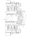
- FIG. 1 is a longitudinal sectional view of an electric actuator according to an embodiment of the present invention.
- the electric actuator 1 shown in FIG. 1 includes a motor unit 2 as a drive source, a driving force transmission mechanism 3 for transmitting the rotational motion of the motor unit 2, and a motion conversion mechanism 4 for converting the rotational motion of the motor unit 2 into linear motion. And is the main component.
- the motor unit 2 is configured of an electric motor 5 such as a DC motor.
- the electric motor 5 is accommodated in a cylindrical motor case 6.
- a connector 7 for connecting a power line or a signal line to the electric motor 5 is attached to one end of the motor case 6 (left end in FIG. 1).
- the driving force transmission mechanism 3 is composed of a drive gear 8 on the drive side and a driven gear 9 on the driven side meshing with the drive gear 8.
- the drive gear 8 and the driven gear 9 are accommodated in the gear case 10.
- the drive gear 8 is a small diameter gear having a smaller number of teeth than the driven gear 9, and is fixed so as not to rotate with respect to the outer peripheral surface of the rotation shaft 5 a of the electric motor 5.
- the driven gear 9 is a large diameter gear having a larger number of teeth than the drive gear 8 and is fixed so as not to rotate with respect to the outer peripheral surface of a nut 17 described later constituting the motion conversion mechanism 4. .
- the drive gear 8 is rotatably supported by two bearings 11 and 12 at both axial ends.
- the two bearings 11 and 12 one (left in FIG. 1) of the bearing 11 is held by being fitted into a cylindrical bearing holding member 13 fixed to the end of the electric motor 5, and the other (see FIG.
- the bearing 12 (right side in 1) is held by being fitted into a bearing holding portion 10 a provided in the gear case 10.
- the driven gear 9 is rotatably supported together with the nut 17 by double-row bearings 14 provided on the outer peripheral surface of the nut 17.
- the double-row bearings 14 are accommodated in a cylindrical sleeve 15 provided on the gear case 10 and fixed by a snap ring 16 mounted on the inner circumferential surface of the sleeve 15.
- the double row bearings 14 are preferably double row angular contact ball bearings. In that case, since the double-row bearing 14 can support axial loads in both directions in addition to the radial load, the motion conversion mechanism 4 can be stably and reliably supported
- the motion conversion mechanism 4 is configured by a ball screw mechanism having a nut 17 as a rotating member, a screw shaft 18 as a linear moving member, and a large number of balls 19. Spiral grooves are formed on the inner peripheral surface of the nut 17 and the outer peripheral surface of the screw shaft 18, respectively, and balls 19 are rollably accommodated between these spiral grooves. Further, the nut 17 is provided with a circulation member (not shown), and the ball 19 is configured to circulate along the spiral groove by this circulation member.
- the screw shaft 18 is inserted into the inner periphery of the nut 17 and disposed parallel to the rotation shaft 5 a of the electric motor 5.
- a hole (connection portion) 18a is provided at the front end (left end in FIG. 1) of the screw shaft 18.
- a fastener such as a bolt
- the corresponding part of the target use device (not shown) is linked.
- the rear end portion (right end portion in FIG. 1) of the screw shaft 18 is covered by a screw shaft case 20.
- the screw shaft case 20 is fixed to the gear case 10 on the opposite side to the motor case 6.
- a detent pin 21 as a rotation restricting member for restricting the rotation of the screw shaft 18 is provided.
- FIG. 2 is a cross-sectional view of the electric actuator taken along line AA of FIG.
- both ends of the locking pin 21 protrude radially outward from the screw shaft 18, and the guide rollers 22 made of resin are separated from the outer peripheral surfaces of both ends of the locking pin 21. And is rotatably inserted. Further, both end portions of the locking pin 21 and the guide rollers 22 are inserted into a pair of guide grooves 20 a provided in the screw shaft case 20.
- the guide groove 20a is formed to extend in the axial direction of the screw shaft 18, and the detent pin 21 and the guide roller 22 are configured to be movable in the axial direction along the guide groove 20a.
- a boot 23 for preventing foreign matter from entering the ball screw mechanism and a boot cover 25 for protecting the boot 23 are provided on the tip end side of the nut 17.
- the boot 23 is composed of a small diameter end 23a, a large diameter end 23b, and a bellows 23c which connects and extends these to extend and contract in the axial direction.
- the small diameter end 23 a is fixed to the outer peripheral surface of the screw shaft 18, and the large diameter end 23 b is fixed to the outer peripheral surface of the cylindrical boot mounting member 24 attached to the boot cover 25.
- the boot cover 25 is disposed so as to cover the outside of the boot 23 and is integrally molded with the motor case 6.
- a magnet 26 for identifying the axial position of the screw shaft 18 is provided on the outer peripheral surface of the screw shaft 18.
- the screw shaft 18 moves in one of the axial directions (forward direction or reverse direction).
- the electric motor 5 is reversely rotated, the driving force is transmitted through the same path as described above, and the screw shaft 18 moves in the other axial direction.
- the rotational torque is increased by the reduction of speed between the drive gear 8 and the driven gear 9, so that the output of the screw shaft 18 can be obtained large, and the electric motor can be miniaturized.
- the drive gear 8 and the driven gear 9 may be configured by gears having the same number of teeth, and rotational motion from the electric motor 5 may be transmitted without decelerating.
- the disc spring 27 is a ring-shaped metal member formed in a truncated cone.
- the small diameter end 27a of the disc spring 27 is disposed so as to face the rear end surface 17a of the nut 17, and the large diameter end 27b opposite thereto is disposed so as to face the locking pin 21.
- an annular protrusion 17 b is provided on the rear end surface 17 a of the nut 17, and the protrusion 17 b is engaged with the inner peripheral surface on the small diameter end 27 a side of the disc spring 27.
- the projection 17 b may not necessarily be formed annularly as long as the radial movement of the disc spring 27 can be restricted.
- the plurality of protrusions 17 b may be provided intermittently along the inner peripheral surface of the disc spring 27.
- the disc spring is disposed between the locking pin and the rear end surface of the nut, so that the locking pin can By contacting the disc spring), a direct collision between the locking pin and the rear end surface of the nut can be avoided.
- the disc spring functions as a buffer member to prevent biting between the nut and the screw shaft.
- the electric actuator according to the present embodiment since biting between the nut and the screw shaft at the time of component assembly can be prevented, handling of the component becomes easy, and workability is improved. Moreover, it is possible to prevent biting without major structural changes. In addition, since it is possible to prevent the parts from being incorporated while the biting between the nut and the screw shaft accidentally occurs, the reliability of the electric actuator is also improved.
- the ball screw mechanism when the ball screw mechanism operates by receiving the driving force from the electric motor, the operation is stopped at a position where biting does not occur between the nut and the screw shaft. It is controlled.
- a coned disc spring is also provided on the front end face of the nut even in the configuration where the locking pin is provided at the front end of the screw shaft.
- elastic members such as a wave spring or a rubber ring.
- the guide roller provided on the locking pin may be made of an elastic member such as hard rubber.
- an elastic member such as a disc spring may be provided on the end face of the nut.
- the elastic member may be provided on one or both of the locking pin and the end face of the nut.
- the present invention is not limited at all to the above-mentioned embodiment, and within the range which does not deviate from the gist of the present invention, it can carry out with various forms. Of course it is.
- a configuration using a ball screw mechanism as the motion conversion mechanism is taken as an example, but the present invention is also applied to an electric actuator provided with a slide screw mechanism having a screw shaft and a nut screwed thereto. It is applicable.
Abstract
モータ部と、モータ部の回転運動を直線運動に変換する運動変換機構とを備える電動アクチュエータにおいて、運動変換機構は、回転可能に支持されたナット17と、ナット17の回転に伴って軸方向に移動するねじ軸18とを有し、ねじ軸18には、その軸心周りの回転を規制する回転規制部材21が外径方向に突出するように設けられ、回転規制部材21とナット17の端面17aとの間に、弾性部材27を設けた。
Description
本発明は、電動アクチュエータに関する。
近年、車両等の省力化、低燃費化のために電動化が進み、例えば、自動車の自動変速機やブレーキ、ステアリング等の操作を電動機の力で行うシステムが開発され、市場に投入されている。このような用途に使用されるアクチュエータとして、電動機の回転運動を直線方向の運動に変換するボールねじ又はすべりねじ等の送りねじ機構を用いた電動アクチュエータが知られている。
送りねじ機構では、ねじ軸とナットのうち、一方が電動モータからの駆動力により回転する回転部材として機能し、他方が回転部材の回転によって直動する直動部材として機能する。一般的に、直動部材は、回転部材の回転運動を効率良く直動運動に変換するため、その軸心周りの回転が規制されていることが多い。
例えば、特許文献1には、直動部材であるねじ軸の回転を規制する回り止め機構として、ねじ軸の端部に外径方向に突出する回転規制部材(係止ピン)を設け、回転規制部材を静止部材であるスリーブに形成された凹溝に係合させることで、ねじ軸の回転を規制する構成が提案されている。
上記特許文献1に提案されている構成では、ナットが回転することにより、ねじ軸が直動方向の力を受けると、ねじ軸に設けられた回転規制部材(係止ピン)が凹溝に係合しつつ凹溝に沿って移動することで、ねじ軸の回転を規制しつつ直動を許容する。
しかしながら、このような回転規制部材を設けた構成においては、回転規制部材がねじ軸の外径方向に突出しているため、部品組立時などにおいて、ねじ軸が外力を受けて軸方向に動かされ、回転規制部材がナットの端面に衝突すると、ねじ軸とナットとの間で噛み込みが発生するといった課題があった。そして、噛み込みが生じたまま送りねじ機構が組み付けられてしまうと、その後、電動モータを駆動させる際に、電動モータによる駆動力では噛み込みを解除することができない場合があった。
そこで、本発明は、ねじ軸に設けられた回転規制部材がナットの端面に衝突することにより発生するねじ軸とナットとの間での噛み込みを防止できる電動アクチュエータを提供することを目的とする。
上記課題を解決するため、本発明は、モータ部と、モータ部の回転運動を直線運動に変換する運動変換機構とを備える電動アクチュエータにおいて、運動変換機構は、回転可能に支持されたナットと、ナットの回転に伴って軸方向に移動するねじ軸とを有し、ねじ軸には、その軸心周りの回転を規制する回転規制部材が外径方向に突出するように設けられ、回転規制部材とナットの端面との間に、弾性部材を設けたことを特徴とする。
このように、本発明に係る電動アクチュエータにおいては、回転規制部材とナットの端面との間に弾性部材が設けられていることで、回転規制部材とナットの端面とが直接衝突するのを回避することができる。このとき、弾性部材が回転規制部材とナットの端面との間で緩衝部材として機能することで、ナットとねじ軸との間の噛み込みを防止することができる。
より具体的には、弾性部材を、皿ばねで構成し、ナットの端面に設ける。この場合、皿ばねが緩衝部材として機能することで、ナットとねじ軸との間の噛み込みを防止することができる。
さらに、ナットの端面に、皿ばねの内周面に係合して皿ばねを支持する突起部を設けることで、ナットの端面から皿ばねが脱落するのを防止することができる。
また、回転規制部材にガイドローラを設け、ガイドローラを弾性部材として構成してもよい。この場合、ガイドローラが緩衝部材として機能することで、ナットとねじ軸との間の噛み込みを防止できるようになる。
ガイドローラの材料として、硬質ゴムを採用することができる。
本発明によれば、回転規制部材がナットの端面に衝突することにより発生するねじ軸とナットとの間での噛み込みを防止できるので、組立時の部品の取り扱いが容易になり、作業性が向上する。しかも、大きな構造変更を伴わずに噛み込みを防止できる。また、誤ってナットとねじ軸との間で噛み込みが生じたまま部品が組み込まれることも回避できるので、電動アクチュエータの信頼性も向上する。
以下、添付の図面に基づき、本発明について説明する。なお、本発明を説明するための各図面において、同一の機能もしくは形状を有する部材や構成部品等の構成要素については、判別が可能な限り同一符号を付すことにより一度説明した後ではその説明を省略する。
図1は、本発明の実施の一形態に係る電動アクチュエータの縦断面図である。
図1に示す電動アクチュエータ1は、駆動源としてのモータ部2と、モータ部2の回転運動を伝達する駆動力伝達機構3と、モータ部2の回転運動を直線運動に変換する運動変換機構4とを主な構成としている。
モータ部2は、DCモータ等の電動モータ5で構成されている。電動モータ5は、筒状のモータケース6内に収容されている。モータケース6の一端部(図1における左端部)には、電動モータ5に動力線あるいは信号線を接続するためのコネクタ部7が取り付けられている。
駆動力伝達機構3は、駆動側のドライブギヤ8と、これと噛み合う被駆動側のドリブンギヤ9とで構成されている。ドライブギヤ8及びドリブンギヤ9は、ギヤケース10内に収容されている。ドライブギヤ8は、ドリブンギヤ9よりも歯数の少ない小径のギヤであり、電動モータ5の回転軸5aの外周面に対して回転しないように固定されている。これに対して、ドリブンギヤ9は、ドライブギヤ8よりも歯数の多い大径のギヤであり、運動変換機構4を構成する後述のナット17の外周面に対して回転しないように固定されている。
また、ドライブギヤ8は、その軸方向の両端部にて2つの軸受11,12によって回転可能に支持されている。2つの軸受11,12のうち、一方(図1において左側)の軸受11は、電動モータ5の端部に固定された筒状の軸受保持部材13内に嵌め込まれることによって保持され、他方(図1において右側)の軸受12は、ギヤケース10に設けられた軸受保持部10a内に嵌め込まれることによって保持されている。ドリブンギヤ9は、ナット17の外周面に設けられた複列の軸受14によってナット17と共に回転可能に支持されている。複列の軸受14は、ギヤケース10に設けられた筒状のスリーブ15内に収容され、スリーブ15の内周面に装着された止め輪16によって固定されている。また、複列の軸受14は、複列アンギュラ玉軸受であることが望ましい。その場合、複列の軸受14は、ラジアル荷重に加えて、両方向のアキシャル荷重を支承できるので、運動変換機構4を安定的かつ確実に支持することができる。
運動変換機構4は、回転部材としてのナット17と、直動部材としてのねじ軸18と、多数のボール19とを有するボールねじ機構で構成されている。ナット17の内周面とねじ軸18の外周面には、それぞれ螺旋状溝が形成されており、これらの螺旋状溝の間にボール19が転動可能に収容されている。また、ナット17には図示しない循環部材が設けられており、この循環部材によってボール19が螺旋状溝に沿って循環するように構成されている。
ねじ軸18は、ナット17の内周に挿通され、電動モータ5の回転軸5aと平行に配置されている。ねじ軸18の前端部(図1における左端部)には、孔部(連結部)18aが設けられており、この孔部18aにボルト等の締結具を挿入することで、ねじ軸18と操作対象である図示しない使用機器の対応部位とが連結される。ねじ軸18の後端部(図1における右端部)は、ねじ軸ケース20によって覆われている。ねじ軸ケース20は、ギヤケース10に対してモータケース6とは反対側に固定されている。
また、ねじ軸18の後端部には、ねじ軸18の回転を規制する回転規制部材としての回り止めピン21が設けられている。
図2は、図1のA-A線で矢視した電動アクチュエータの横断面図である。
図2に示すように、回り止めピン21は、その両端部がねじ軸18から外径方向に突出しており、回り止めピン21の両端部の外周面には、樹脂製のガイドローラ22が隙間を有して回転可能に挿入されている。また、回り止めピン21の両端部及び各ガイドローラ22は、ねじ軸ケース20に設けられた一対のガイド溝20a内に挿入されている。ガイド溝20aは、ねじ軸18の軸方向に延びるように形成されており、回り止めピン21及びガイドローラ22は、ガイド溝20aに沿って軸方向に移動可能に構成されている。
また、ねじ軸18において、ナット17よりも先端部側には、ボールねじ機構内に異物が侵入するのを防止するブーツ23と、ブーツ23を保護するためのブーツカバー25とが設けられている。ブーツ23は、小径端部23aと大径端部23bとこれらを繋いで軸方向に伸縮する蛇腹部23cとで構成されている。小径端部23aはねじ軸18の外周面に固定され、大径端部23bはブーツカバー25に取り付けられた筒状のブーツ装着部材24の外周面に固定されている。ブーツカバー25は、ブーツ23の外側を覆うように配置され、モータケース6と一体成型されている。
また、ねじ軸18の外周面には、ねじ軸18の軸方向位置を特定するための磁石26が設けられている。ねじ軸18が進退すると、これに伴って変化する磁力線の向きを図示しないストロークセンサによって検出することで、ねじ軸18の軸方向位置を把握する仕組みである。
続いて、図1を参照しつつ本実施形態に係る電動アクチュエータの基本動作を説明する。
電動モータ5が駆動を開始し、電動モータ5の回転軸5aが回転すると、回転軸5aに固定されたドライブギヤ8が回転し、これに連動してドリブンギヤ9が回転する。このとき、電動モータ5からの回転運動は、歯数の少ないドライブギヤ8から歯数の多いドリブンギヤ9へ伝達されるので、減速されて回転トルクが増加する。
そして、ドリブンギヤ9と一体的にナット17が回転することで、ねじ軸18が軸方向の一方(前進方向又は後退方向)へ移動する。また、電動モータ5が逆回転した場合は、上記と同様の経路で駆動力が伝達されて、ねじ軸18が軸方向の他方へ移動する。本実施形態では、ドライブギヤ8とドリブンギヤ9間の減速により回転トルクが増加するので、ねじ軸18の出力が大きく得られるようになり、電動モータの小型化を図ることが可能である。なお、これに限らず、ドライブギヤ8とドリブンギヤ9とを同じ歯数のギヤで構成し、電動モータ5からの回転運動を減速せずに伝達するようにしてもよい。
ところで、上述のように、従来の構成では、部品組み立て時などにおいて、ねじ軸が軸方向の力を受けることにより移動すると、回り止めピン(係止ピン)がナットの端面に衝突することにより、ナットとねじ軸との間で噛み込みが発生する場合があった。これに対して、本実施形態に係る電動アクチュエータにおいては、ナットとねじ軸との間の噛み込みを防止するため、図3に示すように、回り止めピン21とナット17の後端面17aとの間に、弾性部材としての皿ばね27を設けている。
皿ばね27は、円錐台に形成されたリング状の金属部材である。本実施形態では、皿ばね27の小径端部27aがナット17の後端面17aの方を向き、これとは反対側の大径端部27bが回り止めピン21の方を向くように配置されている。また、ナット17の後端面17aには環状の突起部17bが設けられており、この突起部17bが皿ばね27の小径端部27a側の内周面に係合している。これにより、皿ばね27は径方向に移動(落下)してねじ軸18と干渉することがないように支持されている。なお、突起部17bは、皿ばね27の径方向の移動を規制できれば、必ずしも環状に形成されていなくてもよい。例えば、皿ばね27の内周面に沿って複数の突起部17bを断続的に設けてもよい。
上記のように、回り止めピンとナットの後端面との間に皿ばねが配置されていることで、部品組み立て時に、ねじ軸が外力を受けて前進したとしても、回り止めピンが(ガイドローラを介して)皿ばねに接触することで、回り止めピンとナットの後端面との直接衝突を回避できる。このとき、皿ばねが緩衝部材として機能することで、ナットとねじ軸との間の噛み込みを防止することができる。
このように、本実施形態に係る電動アクチュエータにおいては、部品組み立て時におけるナットとねじ軸との間の噛み込みを防止することができるので、部品の取り扱いが容易になり、作業性が向上する。しかも、大きな構造変更を伴わずに噛み込みを防止することが可能である。また、誤ってナットとねじ軸との間で噛み込みが生じたまま部品が組み込まれることも回避できるので、電動アクチュエータの信頼性も向上する。
なお、本実施形態に係る電動アクチュエータにおいて、電動モータからの駆動力を受けてボールねじ機構が作動する際は、ナットとねじ軸との間で噛み込みが生じない位置で作動を停止するように制御されている。
本実施形態では、回り止めピンがねじ軸の後端部に設けられているが、反対にねじ軸の前端部に回り止めピンが設けられている構成においても、ナットの前端面に皿ばねを設けることで、同様に回り止めピンとナットの前端面との直接衝突を回避できる。また、皿ばねに代えて、ウェーブスプリング、あるいはゴムリング等の弾性部材を用いることも可能である。
また、回り止めピンに設けられたガイドローラを、硬質ゴム等の弾性部材で構成してもよい。この場合、ねじ軸が外力を受けて前進したとしても、ガイドローラがナットの端面に接触して緩衝部材として機能することで、ナットとねじ軸との間の噛み込みを防止できる。さらに、ガイドローラを弾性部材で構成することに加え、ナットの端面に皿ばね等の弾性部材を設けてもよい。このように、弾性部材は、回り止めピンとナットの端面の両方又は一方に設ければよい。
以上、本発明に係る電動アクチュエータの実施形態について説明したが、本発明は上記実施形態に何ら限定されるものではなく、本発明の要旨を逸脱しない範囲内において、さらに種々なる形態で実施し得ることは勿論のことである。
上記実施形態では、運動変換機構としてボールねじ機構を用いた構成を例に挙げているが、ねじ軸とこれに螺合するナットとを有するすべりねじ機構を備える電動アクチュエータに対しても本発明を適用可能である。
1 電動アクチュエータ
2 モータ部
4 運動変換機構
17 ナット
17b 突起部
18 ねじ軸
21 回り止めピン(回転規制部材)
22 ガイドローラ
27 皿ばね(弾性部材)
2 モータ部
4 運動変換機構
17 ナット
17b 突起部
18 ねじ軸
21 回り止めピン(回転規制部材)
22 ガイドローラ
27 皿ばね(弾性部材)
Claims (5)
- モータ部と、前記モータ部の回転運動を直線運動に変換する運動変換機構とを備える電動アクチュエータにおいて、
前記運動変換機構は、回転可能に支持されたナットと、前記ナットの回転に伴って軸方向に移動するねじ軸とを有し、
前記ねじ軸には、その軸心周りの回転を規制する回転規制部材が外径方向に突出するように設けられ、
前記回転規制部材と前記ナットの端面との間に、弾性部材を設けたことを特徴とする電動アクチュエータ。 - 前記弾性部材を、皿ばねで構成し、前記ナットの端面に設けた請求項1に記載の電動アクチュエータ。
- 前記ナットの端面に、前記皿ばねの内周面に係合して前記皿ばねを支持する突起部を設けた請求項2に記載の電動アクチュエータ。
- 前記回転規制部材にガイドローラを設け、
前記ガイドローラを前記弾性部材として構成した請求項1から3のいずれか1項に記載の電動アクチュエータ。 - 前記ガイドローラを、硬質ゴムで構成した請求項4に記載の電動アクチュエータ。
Applications Claiming Priority (2)
| Application Number | Priority Date | Filing Date | Title |
|---|---|---|---|
| JP2017182337A JP2019056460A (ja) | 2017-09-22 | 2017-09-22 | 電動アクチュエータ |
| JP2017-182337 | 2017-09-22 |
Publications (1)
| Publication Number | Publication Date |
|---|---|
| WO2019059355A1 true WO2019059355A1 (ja) | 2019-03-28 |
Family
ID=65810289
Family Applications (1)
| Application Number | Title | Priority Date | Filing Date |
|---|---|---|---|
| PCT/JP2018/035076 WO2019059355A1 (ja) | 2017-09-22 | 2018-09-21 | 電動アクチュエータ |
Country Status (2)
| Country | Link |
|---|---|
| JP (1) | JP2019056460A (ja) |
| WO (1) | WO2019059355A1 (ja) |
Families Citing this family (1)
| Publication number | Priority date | Publication date | Assignee | Title |
|---|---|---|---|---|
| WO2023204016A1 (ja) * | 2022-04-22 | 2023-10-26 | 日本精工株式会社 | 直動アクチュエータ |
Citations (7)
| Publication number | Priority date | Publication date | Assignee | Title |
|---|---|---|---|---|
| JPH04128523U (ja) * | 1991-05-16 | 1992-11-24 | エヌテイエヌ株式会社 | 直線駆動装置 |
| JPH10119795A (ja) * | 1996-10-17 | 1998-05-12 | Toyota Motor Corp | 回転伝達機構 |
| JPH11150912A (ja) * | 1997-11-19 | 1999-06-02 | Shinko Electric Co Ltd | 電動リニアアクチュエータのメカニカルストップ機構 |
| US20080246421A1 (en) * | 2007-04-04 | 2008-10-09 | Goodrich Actuation Systems Limited | Actuator Arrangement |
| DE102011014922A1 (de) * | 2011-03-24 | 2012-09-27 | Volkswagen Aktiengesellschaft | Elektromechanische Lenkung für ein Fahrzeug und elastischer Endanschlag dazu |
| JP2014088920A (ja) * | 2012-10-30 | 2014-05-15 | Ntn Corp | 電動リニアアクチュエータ |
| JP2016065605A (ja) * | 2014-09-25 | 2016-04-28 | セイコークロック株式会社 | 直線駆動装置及び施錠装置 |
-
2017
- 2017-09-22 JP JP2017182337A patent/JP2019056460A/ja active Pending
-
2018
- 2018-09-21 WO PCT/JP2018/035076 patent/WO2019059355A1/ja active Application Filing
Patent Citations (7)
| Publication number | Priority date | Publication date | Assignee | Title |
|---|---|---|---|---|
| JPH04128523U (ja) * | 1991-05-16 | 1992-11-24 | エヌテイエヌ株式会社 | 直線駆動装置 |
| JPH10119795A (ja) * | 1996-10-17 | 1998-05-12 | Toyota Motor Corp | 回転伝達機構 |
| JPH11150912A (ja) * | 1997-11-19 | 1999-06-02 | Shinko Electric Co Ltd | 電動リニアアクチュエータのメカニカルストップ機構 |
| US20080246421A1 (en) * | 2007-04-04 | 2008-10-09 | Goodrich Actuation Systems Limited | Actuator Arrangement |
| DE102011014922A1 (de) * | 2011-03-24 | 2012-09-27 | Volkswagen Aktiengesellschaft | Elektromechanische Lenkung für ein Fahrzeug und elastischer Endanschlag dazu |
| JP2014088920A (ja) * | 2012-10-30 | 2014-05-15 | Ntn Corp | 電動リニアアクチュエータ |
| JP2016065605A (ja) * | 2014-09-25 | 2016-04-28 | セイコークロック株式会社 | 直線駆動装置及び施錠装置 |
Also Published As
| Publication number | Publication date |
|---|---|
| JP2019056460A (ja) | 2019-04-11 |
Similar Documents
| Publication | Publication Date | Title |
|---|---|---|
| JP5293887B2 (ja) | 直動アクチュエータ | |
| US8893847B2 (en) | Electric power steering system | |
| US8272284B2 (en) | Electronically driven linear actuator | |
| US11204081B2 (en) | Screw shaft, feed screw mechanism, and electric actuator | |
| CN109891723B (zh) | 电动致动器 | |
| WO2018123564A1 (ja) | 電動アクチュエータ | |
| WO2019059355A1 (ja) | 電動アクチュエータ | |
| JP2017180681A (ja) | センサターゲットとこのターゲットを備えた可動部ユニット、並びに電動アクチュエータ | |
| US11428300B2 (en) | Electric actuator | |
| JP7195069B2 (ja) | 電動アクチュエータ | |
| JP2014178023A (ja) | ボールねじ機構及びアクチュエータ | |
| JP2009074623A (ja) | ボールねじ装置および電動パワーステアリング装置 | |
| JP2017180677A (ja) | 電動アクチュエータ | |
| JP2012229800A (ja) | 直動アクチュエータ | |
| JP2019058032A (ja) | 電動アクチュエータ | |
| JP2020048392A (ja) | 電動アクチュエータ | |
| JP2019115159A (ja) | 電動アクチュエータ | |
| JP5866852B2 (ja) | アクチュエータ | |
| JP7152913B2 (ja) | 電動式直動アクチュエータ及び電動ブレーキ装置 | |
| JP2008069793A (ja) | 電動リニアアクチュエータ | |
| JP7224145B2 (ja) | 電動アクチュエータ | |
| JP2020139616A (ja) | 電動アクチュエータ | |
| WO2020004377A1 (ja) | 電動アクチュエータ | |
| JP2023043476A (ja) | 電動アクチュエータ | |
| JP2024034084A (ja) | ねじ機構及びこれを備える直動アクチュエータ |
Legal Events
| Date | Code | Title | Description |
|---|---|---|---|
| 121 | Ep: the epo has been informed by wipo that ep was designated in this application |
Ref document number: 18858123 Country of ref document: EP Kind code of ref document: A1 |
|
| NENP | Non-entry into the national phase |
Ref country code: DE |
|
| 122 | Ep: pct application non-entry in european phase |
Ref document number: 18858123 Country of ref document: EP Kind code of ref document: A1 |