WO2019059353A1 - 表示装置及びテレビジョン受信機 - Google Patents
表示装置及びテレビジョン受信機 Download PDFInfo
- Publication number
- WO2019059353A1 WO2019059353A1 PCT/JP2018/035068 JP2018035068W WO2019059353A1 WO 2019059353 A1 WO2019059353 A1 WO 2019059353A1 JP 2018035068 W JP2018035068 W JP 2018035068W WO 2019059353 A1 WO2019059353 A1 WO 2019059353A1
- Authority
- WO
- WIPO (PCT)
- Prior art keywords
- light guide
- guide plate
- display device
- display panel
- liquid crystal
- Prior art date
- Legal status (The legal status is an assumption and is not a legal conclusion. Google has not performed a legal analysis and makes no representation as to the accuracy of the status listed.)
- Ceased
Links
Images

Classifications
-
- G—PHYSICS
- G02—OPTICS
- G02F—OPTICAL DEVICES OR ARRANGEMENTS FOR THE CONTROL OF LIGHT BY MODIFICATION OF THE OPTICAL PROPERTIES OF THE MEDIA OF THE ELEMENTS INVOLVED THEREIN; NON-LINEAR OPTICS; FREQUENCY-CHANGING OF LIGHT; OPTICAL LOGIC ELEMENTS; OPTICAL ANALOGUE/DIGITAL CONVERTERS
- G02F1/00—Devices or arrangements for the control of the intensity, colour, phase, polarisation or direction of light arriving from an independent light source, e.g. switching, gating or modulating; Non-linear optics
- G02F1/01—Devices or arrangements for the control of the intensity, colour, phase, polarisation or direction of light arriving from an independent light source, e.g. switching, gating or modulating; Non-linear optics for the control of the intensity, phase, polarisation or colour
- G02F1/13—Devices or arrangements for the control of the intensity, colour, phase, polarisation or direction of light arriving from an independent light source, e.g. switching, gating or modulating; Non-linear optics for the control of the intensity, phase, polarisation or colour based on liquid crystals, e.g. single liquid crystal display cells
- G02F1/133—Constructional arrangements; Operation of liquid crystal cells; Circuit arrangements
- G02F1/1333—Constructional arrangements; Manufacturing methods
Definitions
- One embodiment of the present invention relates to a display device and a television receiver.
- Priority is claimed on Japanese Patent Application No. 2017-183857, filed September 25, 2017, the content of which is incorporated herein by reference.
- liquid crystal display devices are widely used as display devices for displaying images.
- the liquid crystal display device is configured such that a backlight is disposed on the back of the liquid crystal panel, light emission of the backlight is modulated by the liquid crystal panel and transmitted, and an image is displayed on the front of the liquid crystal panel.
- an edge light type backlight using an LED (light emitting diode) as a light source is adopted in order to realize reduction in power consumption and thinning.
- the edge light type backlight is configured by storing a light guide plate and a light source in a rectangular plate shaped storage container.
- the light guide plate has a reflective sheet attached to one surface of a transparent resin flat plate such as acrylic, and the storage container is oriented such that the adherend surface of the reflective sheet faces the bottom surface of the storage container and covers the bottom surface.
- Housed in The liquid crystal display device includes a bezel disposed around the periphery of the liquid crystal panel, and the storage container and the bezel are fixed by screws (see, for example, Patent Document 1).
- the storage container provided in the display device described in Patent Document 1 includes a metal frame such as aluminum having a side surface portion and a back surface portion, and a back surface plate (bottom surface) that covers the light guide plate from the back surface. Since the back plate is slidable with respect to the back of the frame and is not fixed to the frame, distortion due to thermal expansion occurs even if the coefficients of thermal expansion of the back plate and the frame are different. Occurrence is suppressed.
- One embodiment of the present invention is made in view of such circumstances, and an object thereof is to provide a display device and the like which can fix a light guide plate and a display panel with a simple configuration.
- a display panel that displays an image on the front and a back surface of the display panel are disposed to face each other, and light emitted from the one surface is irradiated to the back surface of the display panel
- the display panel and the light guide plate are fixed by bonding the respective peripheral edge portions with a gap between the opposing surfaces being separated by an optical sheet.
- a display device or the like which can fix a light guide plate and a display panel with a simple configuration can be provided.
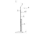
- FIG. 1 is a perspective view schematically illustrating a display device according to Embodiment 1.
- FIG. It is a side view which briefly displays a display apparatus.
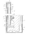
- FIG. 3 is a partial longitudinal sectional view taken along line III-III of FIG.
- FIG. 1 is a perspective view schematically illustrating the display device according to the first embodiment.
- FIG. 2 is a side view schematically illustrating the display device.
- the display device is the liquid crystal display device 1 including the liquid crystal panel 2 as a display panel for image display.
- the liquid crystal display device 1 includes a backlight 4 for irradiating the liquid crystal panel 2 with light.
- the liquid crystal panel 2 has a rectangular plate shape, and includes a display unit that displays an image on the front.
- the back side of the liquid crystal panel 2 is covered by a backlight chassis 43 (storage container) which constitutes an outer casing of the backlight 4.
- the backlight chassis 43 constitutes an exterior body of the liquid crystal display device 1.
- the liquid crystal display device 1 shown in FIG. 1 is configured as a television receiver including a receiving unit 9 and a signal processing unit 10.
- the receiving unit 9 is connected to an antenna (not shown) and receives television broadcast through the antenna.
- the signal processing unit 10 demodulates the data related to the television broadcast received by the receiving unit 9, separates the image data from the demodulated data, and outputs the separated image data.
- the liquid crystal panel 2 displays an image based on the image data output from the signal processing unit 10.
- the liquid crystal display device 1 includes the legs 7.
- the liquid crystal display device 1 is supported by the legs 7 and placed on a flat table, and is used while keeping the display surface of the liquid crystal panel 2 in the vertical posture.
- the display surface side of the liquid crystal panel 2 is referred to as the front, and the other surface is referred to as the rear.
- upper and lower correspond to upper and lower in the above-mentioned use state
- left and right correspond to left and right as viewed from the front side in use.
- FIG. 3 is a partial longitudinal sectional view taken along line III-III of FIG. In this partial longitudinal sectional view, parts of the upper and lower portions of the liquid crystal display device 1 are shown.
- the backlight 4 includes a light guide plate 41 inside the backlight chassis 43.
- the back light chassis 43 is a metal case formed in a shallow bottom dish shape by raising the peripheral edge of a rectangular bottom plate substantially vertically to surround short side walls.
- the light guide plate 41 is a flat plate made of glass or a translucent resin such as an acrylic resin, and is formed in a rectangular shape.
- the light guide plate 41 and the liquid crystal panel 2 are made of materials having substantially the same coefficient of thermal expansion.
- the light guide plate 41 is an optical member in which a reflective sheet is attached to the rear surface (rear surface) of the flat plate, and the reflective sheet 42 is attached to the remaining portion of the light guide plate 41 excluding the peripheral portion.
- the light guide plate 41 is accommodated in the backlight chassis 43 so that the adhesion surface (rear surface) of the reflection sheet 42 faces the side of the bottom plate of the backlight chassis 43 and covers substantially the entire surface of the bottom plate.
- the adhesive layer 13 is provided between the peripheral portion of the light guide plate 41 and the backlight chassis 43, and the light guide plate 41 and the backlight chassis 43 are adhered and fixed by the adhesive layer 13.
- the adhesive layer 13 is, for example, a long strip-shaped double-sided tape.
- the adhesive layer 13 is provided on the entire periphery of the peripheral portion of the surface of the light guide plate 41 on which the reflective sheet 42 is attached, that is, the upper and lower edges and the left and right edges.
- the adhesive layer 13 is not limited to a double-sided tape, but may be formed by applying an adhesive in a long strip shape to form a thickness, and bonding the light guide plate 41 and the backlight chassis 43.
- the light guide plate 41 has a front surface (front surface) facing the liquid crystal panel 2, and the light guide plate 41 and the liquid crystal panel 2 are bonded by an adhesive member 12 provided on the peripheral edge of the facing surface.
- the bonding member 12 is, for example, a long strip-shaped double-sided tape in which the bonding layer 13 is provided on both sides of a thick base material.
- the bonding members 12 are provided all around the periphery of the facing surface, that is, the upper and lower edges and the left and right edges.
- the bonding member 12 is provided in a region corresponding to the black matrix 21 of the liquid crystal panel 2 described later.
- a gap corresponding to the thickness of the bonding member 12 is formed between the light guide plate 41 and the liquid crystal panel 2, and the optical sheet group 3 is interposed in the gap.
- the size of the gap is preferably larger than the thickness of the optical sheet group 3 in the range of 0.2 mm to 0.6 mm. Furthermore, it is desirable to set the distance between the optical sheet group 3 and the liquid crystal panel 2 to about 0.4 mm.
- the bonding member 12 is not limited to the double-sided tape, but may be a thick strip by applying a bonding agent to form a thickness, and bonding the light guide plate 41 and the liquid crystal panel 2.
- the backlight 4 includes an LED 45 and a light source substrate 44 on which the LED 45 is mounted.
- the light source substrate 44 is fixed to the heat spreader 8 screwed to the lower portion on the back side of the backlight chassis 43, and the mounting surface of the LED 45 is provided to face the lower edge of the light guide plate 41.
- the light source substrate 44 is in the form of a long strip having a length corresponding to the lower edge of the light guide plate 41, and the LEDs 45 are mounted side by side in the longitudinal direction of the light source substrate 441.
- the heat generated by the lighting of the LED 45 is dissipated through the heat spreader 8 and the back light chassis 43.
- the liquid crystal panel 2 has a known configuration in which liquid crystal is sealed between an array substrate and a color filter substrate, and polarizing plates are laminated on both sides of these.
- the liquid crystal panel 2 is made of glass or a transparent resin such as an acrylic resin.
- a black matrix 21 for forming an area through which light for displaying an image is not transmitted is provided in the peripheral portion of the liquid crystal panel 2.
- the liquid crystal sealed between the array substrate and the color filter substrate is driven by the liquid crystal drive substrate 11 connected to the liquid crystal panel 2 via a lead.
- a side plate 5 is provided to face the outer surface of the side wall of the back light chassis 43.
- the side plate 5 has a rectangular plate shape, is made of resin or metal, and forms an outer shell of the side surface of the liquid crystal display device 1.
- the side plates 5 are provided on the upper portion and the left and right side walls of the backlight chassis 43.
- the length in the longitudinal direction of the side plate 5 is set to be substantially the same as the length of the side wall of the corresponding backlight chassis 43.
- the backlight chassis 43 and the side plate 5 are adhered and fixed by a double-sided tape or an adhesive provided between the outer surface of the side wall of the backlight chassis 43 and the inner surface of the side plate 5.
- the side plate 5 is made of resin, the backlight chassis 43 and the side plate 5 may be welded and fixed.
- the liquid crystal display device 1 includes a box-shaped cover 6.
- the cover 6 is disposed on the lower side of the liquid crystal display panel, and is provided to cover the backlight chassis 43 from the rear side.
- the light emitted from the LED 45 is incident on the light guide plate 41 through the lower edge facing the light source substrate 44, and is totally reflected by the reflection sheet attached to the rear surface (other surface) inside the light guide plate 41 and the front surface (one surface). The partial reflection is repeated and proceeds to be distributed over the entire front surface of the light guide plate 41 and emitted.
- the emitted light is diffused by the optical sheet group 3 and irradiated to the back surface of the liquid crystal panel 2, and the liquid crystal panel 2 modulates and transmits the emitted light from the backlight 4 by driving of the liquid crystal sealed therein. Display the image on the front.
- the light guide plate 41 and the liquid crystal panel 2 are bonded by the adhesive member 12 provided on the peripheral portion between the facing surfaces, the light guide plate 41 and the liquid crystal panel 2 can be fixed with a simple configuration.
- the thickness of the bonding member 12 is set so that the gap between the facing surfaces of the light guide plate 41 and the liquid crystal panel 2 is larger than the thickness of the optical sheet group 3 in the range of 0.2 mm to 0.6 mm. Is desirable.
- the thickness of the bonding member 12 is set by setting the thickness of the bonding member 12 so that the gap between the facing surfaces of the light guide plate 41 and the liquid crystal panel 2 is larger than the thickness of the optical sheet group 3 in the range of 0.2 mm to 0.6 mm. An appropriate distance between the optical sheet group 3 and the liquid crystal panel 2 can be secured while reducing the thickness of the display device 1.
- the light guide plate 41 and the liquid crystal panel 2 thermally expand and expand in the respective thickness directions, a sufficient distance between the light guide plate 41 and the liquid crystal panel 2 can be secured.
- an appropriate distance by setting the distance between the optical sheet group 3 and the liquid crystal panel 2 to, for example, 0.4 mm, an image can be clearly displayed on the display unit of the liquid crystal display panel.
- the gap between the facing surfaces of the light guide plate 41 and the liquid crystal panel 2 may be 0.1 mm to 2 mm. By setting the gap to 2 mm or less, the tolerance to the change of the optical sheet group 3 can be increased. Further, by setting the gap to 0.1 mm or more, the load on the optical sheet group 3 can be reduced while the optical sheet group 3 and the liquid crystal panel 2 are substantially in close contact with each other. Thinning can be further promoted.
- the bonding members 12 are provided in the region of the black matrix 21 of the liquid crystal panel 2, it is possible to avoid affecting the image displayed on the display unit of the liquid crystal panel 2.
- the light guide plate 41 and the liquid crystal panel 2 are made of materials having substantially the same coefficient of thermal expansion. Even if the light guide plate 41 and the liquid crystal panel 2 thermally expand due to the heat generated with the light emission of the LED 45, the shear stress generated in the adhesive member 12 can be reduced, and the adhesive function of the adhesive member 12 can be secured.
- the thermal expansion coefficient is substantially the same, when a shear stress is generated in the bonding member 12 due to the difference between the respective thermal expansion coefficients, the thermal expansion coefficient of each bonding member 12 is not impaired by the shearing stress. Means that the difference between Therefore, materials made of materials having substantially the same coefficient of thermal expansion are not limited to the case where the light guide plate 41 and the liquid crystal panel 2 are made of the same material such as glass or acrylic resin, etc. Also, the thermal expansion coefficients may be substantially the same.
- the back light chassis 43 and the light guide plate 41 are bonded by the adhesive layer 13 provided on the peripheral portion between the facing surfaces, it is possible to fix the light guide plate 41 and the back light chassis 43 with a simple configuration. it can.
- fixing the light guide plate 41 to the liquid crystal panel 2 and the backlight chassis 43 it is possible to suppress the occurrence of positional deviation among the light guide plate 41, the liquid crystal panel 2 and the backlight chassis 43.
- the back light chassis 43 of iron and making the light guide plate 41 of glass the difference in thermal expansion coefficient between the back light chassis 43 and the light guide plate 41 can be reduced.
- the difference in thermal expansion coefficient between the backlight chassis 43 and the light guide plate 41 By reducing the difference in thermal expansion coefficient between the backlight chassis 43 and the light guide plate 41, when the backlight chassis 43 and the light guide plate 41 thermally expand, the shear stress generated in the adhesive layer 13 is reduced, and the adhesive layer 13 adhesive functions can be secured. Further, by reducing the difference in thermal expansion coefficient between the backlight chassis 43 and the light guide plate 41, the distance between the inner surface of the side wall of the backlight chassis 43 and the side surface of the light guide plate 41 facing the inner surface is reduced. It is possible to reduce the amount of money. Further, for example, by making the back light chassis 43 of iron and making the liquid crystal display panel of glass, the difference in thermal expansion coefficient between the back light chassis 43 and the liquid crystal display panel can be reduced.
- the inner surface of the side plate 5 bonded to the side wall of the backlight chassis 43 and the side surface of the liquid crystal panel 2 facing the inner surface It is possible to reduce the distance by reducing the distance.
- the appearance of the liquid crystal display device 1 can be improved.
- the side plate 5 and the back light chassis 43 are bonded by a double-sided tape or an adhesive provided between the outer surface of the side wall of the back light chassis 43 and the inner surface of the side plate 5. And the side plate 5 can be fixed.
- a display panel 2 for displaying an image on the front and a back surface of the display panel 2 are disposed opposite to each other, and light emitted from the one surface is the display panel
- the display panel 2 and the light guide plate 41 separate the gap between the opposing surfaces by the adhesion of the respective peripheral portions. It is characterized in that it is fixed.
- the display panel 2 and the light guide plate 41 can be fixed with a simple configuration by bonding at the periphery of the facing surface of the display panel 2 and the light guide plate 41.
- the display device 1 is characterized in that the display panel 2 and the light guide plate 41 are made of materials having substantially the same coefficient of thermal expansion.
- the display panel 2 and the light guide plate 41 made of materials having substantially the same coefficient of thermal expansion, excessive shear stress is generated at the bonded portion even if the display panel 2 and the light guide plate 41 thermally expand. Can be suppressed, and secure fixing of the display panel 2 and the light guide plate 41 can be secured.
- the display device 1 is characterized in that the width of the gap is larger than the thickness of the optical sheet 3 in a range of 0.2 mm or more and 0.6 mm or less.
- the width of the gap between the facing surfaces where the display panel 2 and the light guide plate 41 are bonded is thicker than the thickness of the optical sheet 3 in the range of 0.1 mm or more and 2 mm or less . Therefore, an appropriate distance can be secured between the optical sheet 3 and the display panel 2, and an image can be clearly displayed on the display unit of the liquid crystal panel.
- the display device 1 according to the embodiment of the present disclosure is characterized in that the width of the gap is 0.1 mm or more and 2 mm or less.
- the width of the gap between the facing surfaces where the display panel 2 and the light guide plate 41 are bonded is set in the range of 0.1 mm or more and 2 mm or less. Therefore, the tolerance to the change of the optical sheet 3 can be increased, and while the optical sheet 3 and the display panel 2 are in close contact with each other, the load on the optical sheet 3 is reduced, and the display device 1 is thinned. Can proceed.
- the display device 1 is characterized in that the light guide plate 41 and the display panel 2 are bonded in a region of the black matrix 21 of the display panel 2.
- the portion of the display panel 2 bonded to the light guide plate 41 is in the area of the black matrix 21 of the display panel 2, and thus the image on the display portion of the display panel 2 is affected. It can be avoided.
- the display device 1 includes a plate-shaped storage container 43 that stores the light guide plate 41 so as to cover the other surface side, and the storage container 43 and the light guide plate 41 have opposing surfaces. It is characterized in that it is bonded at the periphery.
- the light guide plate 41 stored in the storage container 43 can be fixed with a simple configuration.
- the occurrence of positional deviation between the light guide plate 41, the display panel 2 and the storage container 43 can be suppressed.
- the display device 1 is characterized by including a side plate 5 fixed to the outer side surface of the storage container 43.
- the appearance of the display device 1 can be improved.
- a display device 1 according to an embodiment of the present disclosure includes the display device 1 according to an embodiment of the present disclosure, and a receiving unit 9 that receives a television broadcast, and based on the television broadcast received by the receiving unit 9 An image is displayed on the display panel 2.
- the present embodiment by using the above-described display device 1, it is possible to provide a television receiver in which the display panel 2 and the light guide plate 41 are fixed with a simple configuration.
Landscapes
- Physics & Mathematics (AREA)
- Nonlinear Science (AREA)
- Liquid Crystal (AREA)
- Mathematical Physics (AREA)
- Chemical & Material Sciences (AREA)
- Crystallography & Structural Chemistry (AREA)
- General Physics & Mathematics (AREA)
- Optics & Photonics (AREA)
- Planar Illumination Modules (AREA)
Abstract
本発明は、簡易な構成で導光板及び表示パネルを固定することができる表示装置を提供することを目的とする。 本発明の表示装置は、正面に画像を表示する表示パネル(2)と、該表示パネル(2)の背面に一面を対向させて配してあり、前記一面からの出射光を表示パネル(2)の背面に照射させる導光板(41)とを備える。表示装置の前記表示パネル(2)と前記導光板(41)とは、夫々の周縁部の接着により、対向面間に光学シート(3)が介在する隙間を隔てて、固定してある。
Description
本発明の一態様は、表示装置及びテレビジョン受信機に関する。
本願は、2017年9月25日に、日本に出願された特願2017-183857号に基づき優先権を主張し、その内容をここに援用する。
本願は、2017年9月25日に、日本に出願された特願2017-183857号に基づき優先権を主張し、その内容をここに援用する。
近年、画像を表示する表示装置として、液晶表示装置が広く普及している。液晶表示装置は、液晶パネルの背面にバックライトを配置し、バックライトの発光を液晶パネルにより変調して透過させ、液晶パネルの正面に画像を表示するように構成されている。表示装置においては、近年、消費電力の低減と薄型化とを併せて実現するために、LED(発光ダイオード)を光源とするエッジライト型のバックライトが採用されている。
エッジライト型のバックライトは、矩形皿形の収納容器内に導光板及び光源を収納して構成されている。導光板は、アクリル等の透光性を有する樹脂製の平板の一面に反射シートを被着してなり、反射シートの被着面を収納容器の底面に向け、該底面を覆うように収納容器に収納されている。液晶表示装置は、液晶パネルの周縁に配されるベゼルを備え、収納容器とベゼルとは、ネジによって固定してある(例えば、特許文献1参照)。
特許文献1に記載の表示装置が備える収納容器は、側面部及び背面部を有するアルミ等の金属製のフレームと、導光板を背面から覆う背面プレート(底面)を有している。背面プレートは、フレームの背面部に対して摺動可能であり、フレームに対して固定されていないため、背面プレートとフレームとの熱膨張率が異なる場合であっても、熱膨張に起因した歪みの発生が抑制される。
しかしながら、特許文献1の表示装置は、収納容器のフレームとベゼルとをネジによって固定し、導光板及び液晶パネルを挟持しているため、固定構造が複雑になるという問題がある。
本発明の一態様は、斯かる事情に鑑みてされたものであり、簡易な構成で導光板及び表示パネルを固定することができる表示装置等を提供することを目的とする。
本開示の実施形態に係る表示装置は、正面に画像を表示する表示パネルと、該表示パネルの背面に一面を対向させて配してあり、前記一面からの出射光を表示パネルの背面に照射させる導光板とを備える表示装置において、前記表示パネルと前記導光板とは、夫々の周縁部の接着により、対向面間に光学シートが介在する隙間を隔てて、固定してあることを特徴とする。
本発明の一態様によれば、簡易な構成で導光板及び表示パネルを固定することができる表示装置等を提供することができる。
以下、本発明の実施の形態について説明する。図1は、実施形態1に係る表示装置を略示する斜視図である。図2は、表示装置を略示する側面図である。表示装置は、画像表示用の表示パネルとして液晶パネル2を備えた液晶表示装置1である。液晶表示装置1は、該液晶パネル2に光を照射するバックライト4を備えている。
液晶パネル2は、矩形板状をなし、正面に画像を表示する表示部を備えている。液晶パネル2の背面側は、バックライト4の外筐を構成するバックライトシャーシ43(収納容器)により覆われている。バックライトシャーシ43は、液晶表示装置1の外装体を構成している。
図1に示す液晶表示装置1は、受信部9及び信号処理部10を備えるテレビジョン受信機として構成されている。受信部9には、図示しないアンテナに接続され、該アンテナを介してテレビジョン放送を受信する。信号処理部10は、受信部9が受信したテレビジョン放送に係るデータを復調し、復調したデータから画像データを分離し、分離した画像データを出力する。液晶パネル2は、信号処理部10が出力した画像データに基づく画像を表示する。
液晶表示装置1は、脚7を備えている。液晶表示装置1は、脚7で支えられて平坦な台上に載置され、液晶パネル2の表示面を縦姿勢に保って使用される。以下の説明においては、液晶パネル2の表示面側を前、他面を後とする。また、以下の説明において使用する上、下は、前述した使用状態での上、下に対応し、同じく左、右は、使用状態において前側から見て左、右に対応する。
図3は、図1のIII-III線による部分縦断面図である。この部分縦断面図には、液晶表示装置1の上下夫々の一部が示されている。バックライト4は、バックライトシャーシ43の内部に導光板41を備えている。バックライトシャーシ43は、矩形の底板の周縁を略垂直に立ち上げて短寸の側壁を周設し、浅底皿形に成形された金属製の筐体である。
導光板41は、ガラス製、又はアクリル樹脂等の透光性を有する樹脂製の平板であり、矩形に成形されている。導光板41と液晶パネル2とは、熱膨張率が略同じ材料製である。導光板41は、平板の後側の面(後面)に反射シートを被着した光学部材であり、反射シート42は、導光板41の周縁部を除いた残部に被着してある。
導光板41は、反射シート42の被着面(後面)を、バックライトシャーシ43の底板の側に向け、該底板の略全面を覆うようにバックライトシャーシ43に収容されている。導光板41の周縁部とバックライトシャーシ43との間には、接着層13が設けられてあり、導光板41とバックライトシャーシ43とは、接着層13によって接着され固定してある。接着層13は、例えば、長寸短冊状の両面テープである。接着層13は、反射シート42の被着された側の導光板41の面の周縁部の全周、すなわち上下縁部及び左右縁部に設けられている。接着層13は、両面テープに限定されず、接着剤を長寸短冊状に塗布して厚みを形成し、導光板41とバックライトシャーシ43とを接着するものであってもよい。
導光板41は、前側の面(前面)を液晶パネル2に対向しており、導光板41と液晶パネル2とは、対向面の周縁部に設けられた接着部材12によって、接着されている。接着部材12は、例えば、厚肉の基材の両面に接着層13を設けた長寸短冊状の両面テープである。接着部材12は、対向面の周縁部の全周、すなわち上下縁部及び左右縁部に設けられている。接着部材12は、後述する液晶パネル2のブラックマトリックス21に対応する領域に設けられている。導光板41と液晶パネル2との間には、接着部材12の厚さ相当分の隙間が形成され、この隙間に光学シート群3が介装されている。隙間の寸法の大きさは、光学シート群3の厚みの寸法より、0.2mmから0.6mmの範囲で大きくしてあることが望ましい。更に、光学シート群3と液晶パネル2との距離を0.4mm程度に設定することが望ましい。なお、接着部材12は、両面テープに限定されず、接着剤を長寸短冊状に塗布して厚みを形成し、導光板41と液晶パネル2とを接着するものであってもよい。
バックライト4は、LED45、及び一面にLED45を実装した光源基板44を備えている。光源基板44は、バックライトシャーシ43の背面側の下部にネジ止めされたヒートスプレッタ8に固定され、LED45の実装面を導光板41の下縁に対向させて設けられている。光源基板44は、導光板41の下縁に対応する長さを有する長寸短冊状をなし、LED45は、光源基板441の長手方向に複数並べて実装されている。LED45が点灯することによって発生した熱は、ヒートスプレッタ8及びバックライトシャーシ43を介して、放熱される。
液晶パネル2は、アレー基板とカラーフィルタ基板との間に液晶を封入し、これらの両面に偏光板を積層してなる公知の構成を有している。液晶パネル2は、ガラス製又はアクリル樹脂等の透明な樹脂製である。液晶パネル2の周縁部には、画像を表示するための光が透過しない領域を形成するためのブラックマトリックス21が設けられている。アレー基板とカラーフィルタ基板との間に封入された液晶は、液晶パネル2にリードを介して接続された液晶駆動基板11によって駆動される。
バックライトシャーシ43の側壁の外面に対向して、側板5が設けられている。側板5は、矩形板状をなし、樹脂製又は金属製であり、液晶表示装置1の側面の外郭を構成する。側板5は、バックライトシャーシ43の上部及び左右の側壁に設けられている。側板5の長手方向の長さは、対応するバックライトシャーシ43の側壁の長さと略同じに設定してある。バックライトシャーシ43と側板5とは、バックライトシャーシ43の側壁の外面と側板5の内面との間に設けた両面テープ又は接着剤によって接着させ固着してある。側板5が樹脂製の場合、バックライトシャーシ43と側板5とは、溶着させ固着してもよい。
液晶表示装置1は、箱状のカバー6を備える。カバー6は、液晶表示パネルの下部側に配され、バックライトシャーシ43を背面側から覆うように設けられている。
LED45の発光は、光源基板44に対向する下縁を経て導光板41に入射し、導光板41の内部で後面(他面)に被着した反射シートでの全反射と前面(一面)での部分反射を繰り返して進行し、導光板41の前面全体に分布して出射される。この出射光は、光学シート群3により拡散されて液晶パネル2の背面に照射され、液晶パネル2は、バックライト4からの出射光を内部に封入された液晶の駆動により変調して透過させ、前面に画像を表示する。
導光板41と液晶パネル2とは、対向面の間の周縁部に設けられた接着部材12によって接着してあるので、簡易な構成で導光板41と液晶パネル2とを固定することができる。
導光板41と液晶パネル2との対向面間の隙間は、光学シート群3の厚みよりも0.2mmから0.6mmの範囲で大きくなるように、接着部材12の厚みを設定してあることが望ましい。導光板41と液晶パネル2との対向面間の隙間を、光学シート群3の厚みよりも0.2mmから0.6mmの範囲で大きくなるように接着部材12の厚みを設定することで、液晶表示装置1の厚みを薄くしつつ、光学シート群3と液晶パネル2との適切な距離を確保することができる。又、導光板41と液晶パネル2とが熱膨張し、夫々の厚み方向に膨張した場合であっても、導光板41と液晶パネル2との十分な距離を確保することができる。光学シート群3と液晶パネル2との距離を例えば0.4mmとして適切な距離を確保することによって、液晶表示パネルの表示部に画像を鮮明に表示することができる。また、導光板41と液晶パネル2との対向面間の隙間を0.1mmから2mmとしてもよい。当該隙間を2mm以下とすることで、光学シート群3の変化への許容を大きくすることができる。また、当該隙間を0.1mm以上とすることで、光学シート群3と液晶パネル2とをほぼ密着しつつ、光学シート群3への押さえつける負荷を低減することができ、更に液晶表示装置1の薄型化をより進めることができる。
接着部材12は、液晶パネル2のブラックマトリックス21の領域に設けられてあるので、液晶パネル2の表示部に表示される画像に影響を与えることを回避することができる。
導光板41及び液晶パネル2は熱膨張率が略同じ材料製である。LED45の発光に伴って発生する熱によって、導光板41及び液晶パネル2が熱膨張しても、接着部材12に発生する剪断応力を小さくし、接着部材12の接着機能を担保することができる。熱膨張率が略同じとは、夫々の熱膨張率の差異によって接着部材12に剪断応力が発生した際、当該剪断応力によって接着部材12の接着機能が損なわれない程度に、夫々の熱膨張率の差異が小さいことを意味する。従って、熱膨張率が略同じ材料製とは、導光板41及び液晶パネル2を、共にガラス製、又はアクリル樹脂製等として、同一の材料製とする場合に限定されず、異なる材料であっても、熱膨張率が略同じであればよい。
バックライトシャーシ43と導光板41とは、対向面の間の周縁部に設けられた接着層13によって接着してあるので、簡易な構成で導光板41とバックライトシャーシ43とを固定することができる。導光板41と、液晶パネル2及びバックライトシャーシ43とを夫々固定することによって、導光板41、液晶パネル2及びバックライトシャーシ43の夫々の間における位置ずれの発生を抑制することができる。また、例えば、バックライトシャーシ43を鉄製とし、導光板41をガラス製とすることで、バックライトシャーシ43と導光板41との熱膨張率の差異を小さくすることができる。バックライトシャーシ43と導光板41との熱膨張率の差異を小さくすることで、バックライトシャーシ43及び導光板41とが熱膨張した場合、接着層13に発生する剪断応力を小さくし、接着層13の接着機能を担保することができる。また、バックライトシャーシ43と導光板41との熱膨張率の差異を小さくすることによって、バックライトシャーシ43の側壁の内面と、当該内面に対向する導光板41の側面との距離を小さくし、狭額化を図ることができる。また、例えば、バックライトシャーシ43を鉄製とし、液晶表示パネルをガラス製とすることで、バックライトシャーシ43と液晶表示パネルとの熱膨張率の差異を小さくすることができる。バックライトシャーシ43と液晶表示パネルとの熱膨張率の差異を小さくすることで、バックライトシャーシ43の側壁に接着してある側板5の内面と、当該内面に対向する液晶パネル2の側面との距離を小さくし、狭額化を図ることができる。
側板5をバックライトシャーシ43の側壁の外面に接着することによって、液晶表示装置1の美観を向上させることができる。側板5とバックライトシャーシ43とは、バックライトシャーシ43の側壁の外面と側板5の内面との間に設けられた両面テープ又は接着剤によって接着してあるので、簡易な構成でバックライトシャーシ43と側板5とを固定することができる。
本開示の実施形態に係る表示装置1は、正面に画像を表示する表示パネル2と、該表示パネル2の背面に一面を対向させて配してあり、前記一面からの出射光を前記表示パネル2の背面に照射させる導光板41とを備える表示装置1において、前記表示パネル2と前記導光板41とは、夫々の周縁部の接着により、対向面間に光学シート3が介在する隙間を隔てて、固定してあることを特徴とする。
本実施形態によれば、表示パネル2と導光板41との対向面の周縁部にて、接着することによって、簡易な構成で表示パネル2と導光板41とを固定することができる。
本開示の実施形態に係る表示装置1は、前記表示パネル2及び導光板41は、熱膨張率が略同じ材料製であることを特徴とする。
本実施形態によれば、表示パネル2及び導光板41を熱膨張率が略同じ材料製とすることで、表示パネル2及び導光板41が熱膨張しても、接着した箇所に過度な剪断応力が発生することを抑制し、表示パネル2及び導光板41の確実な固定を担保することができる。
本開示の実施形態に係る表示装置1は、前記隙間の幅は、前記光学シート3の厚みよりも0.2mm以上、0.6mm以下の範囲で大きくしてあることを特徴とする。
本実施形態によれば、表示パネル2と導光板41とが接着してある対向面間の隙間の幅は、光学シート3の厚みよりも0.1mm以上、2mm以下の範囲で厚くしてある。従って、光学シート3と表示パネル2との間で適切な距離を確保でき、液晶パネルの表示部に画像を鮮明に表示することができる。
本開示の実施形態に係る表示装置1は、前記隙間の幅は、0.1mm以上、2mm以下であることを特徴とする。
本実施形態によれば、表示パネル2と導光板41とが接着してある対向面間の隙間の幅は、0.1mm以上、2mm以下の範囲で設定してある。従って、光学シート3の変化への許容を大きくすることができ、また光学シート3と表示パネル2とを、略密着させつつ、光学シート3への押さえつける負荷を低減し、表示装置1の薄型化を進めることができる。
本開示の実施形態に係る表示装置1は、前記導光板41と前記表示パネル2とは、該表示パネル2のブラックマトリックス21の領域内で接着してあることを特徴とする。
本実施形態によれば、導光板41と接着している表示パネル2の箇所は、表示パネル2のブラックマトリックス21の領域内にあるので、表示パネル2の表示部における画像に影響を与えることを回避することができる。
本開示の実施形態に係る表示装置1は、前記導光板41を他面側から覆うように収納する皿形の収納容器43を備え、前記収納容器43と前記導光板41とは、対向面の周縁部にて接着してあることを特徴とする。
本実施形態によれば、簡易な構成で、収納容器43に収納した導光板41を固定することができる。導光板41と、表示パネル2及び収納容器43とを夫々固定することによって、導光板41、表示パネル2及び収納容器43の夫々の間における位置ずれの発生を抑制することができる。
本開示の実施形態に係る表示装置1は、前記収納容器43の外側の側面に固着された側板5を備えることを特徴とする。
本実施形態によれば、収納容器43の外側の側面に側板5を固着し、収納容器43の外側の側面を露出させないようにすることによって、表示装置1の美観を向上させることができる。
本開示の実施形態に係る表示装置1は、本開示の実施形態に係る表示装置1と、テレビジョン放送を受信する受信部9とを備え、前記受信部9で受信したテレビジョン放送に基づいて前記表示パネル2に画像を表示するようにしてあることを特徴とする。
本実施形態によれば、上述の表示装置1を用いることにより、簡易な構成で表示パネル2と導光板41とを固定してあるテレビジョン受信機を提供することができる。
今回開示された実施形態はすべての点で例示であって、制限的なものではないと考えられるべきである。本発明の範囲は、上述した意味ではなく、特許請求の範囲によって示され、特許請求の範囲と均等の意味及び範囲内でのすべての変更が含まれることが意図される。
Claims (8)
- 正面に画像を表示する表示パネルと、
該表示パネルの背面に一面を対向させて配してあり、前記一面からの出射光を前記表示パネルの背面に照射させる導光板と
を備える表示装置において、
前記表示パネルと前記導光板とは、夫々の周縁部の接着により、対向面間に光学シートが介在する隙間を隔てて、固定してあることを特徴とする表示装置。 - 前記表示パネル及び導光板は、熱膨張率が略同じ材料製である
ことを特徴とする請求項1に記載の表示装置。 - 前記隙間の幅は、前記光学シートの厚みよりも0.2mm以上、0.6mm以下の範囲で大きくしてある
ことを特徴とする請求項1又は請求項2に記載の表示装置。 - 前記隙間の幅は、0.1mm以上、2mm以下である
ことを特徴とする請求項1又は請求項2に記載の表示装置。 - 前記導光板と前記表示パネルとは、該表示パネルのブラックマトリックスの領域内で接着してある
ことを特徴とする請求項1から請求項4のいずれか一つに記載の表示装置。 - 前記導光板を他面側から覆うように収納する皿形の収納容器を備え、
前記収納容器と前記導光板とは、対向面の周縁部にて接着してある
ことを特徴とする請求項1から請求項5のいずれか一つに記載の表示装置。 - 前記収納容器の外側の側面に固着された側板を備えることを特徴とする請求項6に記載の表示装置。
- 請求項1から請求項7のいずれか1つに記載の表示装置と、
テレビジョン放送を受信する受信部と
を備え、
前記受信部で受信したテレビジョン放送に基づいて前記表示パネルに画像を表示するようにしてあることを特徴とするテレビジョン受信機。
Applications Claiming Priority (2)
| Application Number | Priority Date | Filing Date | Title |
|---|---|---|---|
| JP2017183857A JP6531146B2 (ja) | 2017-09-25 | 2017-09-25 | 表示装置及びテレビジョン受信機 |
| JP2017-183857 | 2017-09-25 |
Publications (1)
| Publication Number | Publication Date |
|---|---|
| WO2019059353A1 true WO2019059353A1 (ja) | 2019-03-28 |
Family
ID=65809891
Family Applications (1)
| Application Number | Title | Priority Date | Filing Date |
|---|---|---|---|
| PCT/JP2018/035068 Ceased WO2019059353A1 (ja) | 2017-09-25 | 2018-09-21 | 表示装置及びテレビジョン受信機 |
Country Status (2)
| Country | Link |
|---|---|
| JP (1) | JP6531146B2 (ja) |
| WO (1) | WO2019059353A1 (ja) |
Cited By (1)
| Publication number | Priority date | Publication date | Assignee | Title |
|---|---|---|---|---|
| CN112859448A (zh) * | 2021-03-17 | 2021-05-28 | 重庆京东方显示照明有限公司 | 胶带、背光模组、显示装置和背光模组的制备方法 |
Families Citing this family (2)
| Publication number | Priority date | Publication date | Assignee | Title |
|---|---|---|---|---|
| WO2019230515A1 (ja) * | 2018-05-31 | 2019-12-05 | パナソニックIpマネジメント株式会社 | 画像表示装置 |
| JP6889816B1 (ja) * | 2019-08-23 | 2021-06-18 | ミネベアミツミ株式会社 | 面状照明装置 |
Citations (4)
| Publication number | Priority date | Publication date | Assignee | Title |
|---|---|---|---|---|
| US20140176867A1 (en) * | 2012-11-14 | 2014-06-26 | Shenzhen China Star Optoelectronics Technology Co, Ltd. | Edge type backlight module and liquid crystal display for preventing light leakage |
| US20150355506A1 (en) * | 2014-06-09 | 2015-12-10 | Samsung Display Co., Ltd. | Liquid crystal display |
| WO2016139718A1 (ja) * | 2015-03-02 | 2016-09-09 | 堺ディスプレイプロダクト株式会社 | 表示装置及び表示装置の製造方法 |
| CN206209230U (zh) * | 2016-10-12 | 2017-05-31 | 合肥惠科金扬科技有限公司 | 无边框显示器防漏光结构及无边框显示器 |
-
2017
- 2017-09-25 JP JP2017183857A patent/JP6531146B2/ja active Active
-
2018
- 2018-09-21 WO PCT/JP2018/035068 patent/WO2019059353A1/ja not_active Ceased
Patent Citations (4)
| Publication number | Priority date | Publication date | Assignee | Title |
|---|---|---|---|---|
| US20140176867A1 (en) * | 2012-11-14 | 2014-06-26 | Shenzhen China Star Optoelectronics Technology Co, Ltd. | Edge type backlight module and liquid crystal display for preventing light leakage |
| US20150355506A1 (en) * | 2014-06-09 | 2015-12-10 | Samsung Display Co., Ltd. | Liquid crystal display |
| WO2016139718A1 (ja) * | 2015-03-02 | 2016-09-09 | 堺ディスプレイプロダクト株式会社 | 表示装置及び表示装置の製造方法 |
| CN206209230U (zh) * | 2016-10-12 | 2017-05-31 | 合肥惠科金扬科技有限公司 | 无边框显示器防漏光结构及无边框显示器 |
Cited By (3)
| Publication number | Priority date | Publication date | Assignee | Title |
|---|---|---|---|---|
| CN112859448A (zh) * | 2021-03-17 | 2021-05-28 | 重庆京东方显示照明有限公司 | 胶带、背光模组、显示装置和背光模组的制备方法 |
| CN112859448B (zh) * | 2021-03-17 | 2023-03-14 | 重庆京东方显示照明有限公司 | 胶带、背光模组、显示装置和背光模组的制备方法 |
| US11709311B2 (en) | 2021-03-17 | 2023-07-25 | Chongqing Boe Display Lighting Co., Ltd. | Adhesive tape, backlight module, display device and method for manufacturing backlight module |
Also Published As
| Publication number | Publication date |
|---|---|
| JP6531146B2 (ja) | 2019-06-12 |
| JP2019060969A (ja) | 2019-04-18 |
Similar Documents
| Publication | Publication Date | Title |
|---|---|---|
| US10371887B2 (en) | Display apparatus with U-shaped coupling member | |
| KR20070042909A (ko) | 백라이트 장치 | |
| US20140036197A1 (en) | Liquid Crystal Module and Liquid Crystal Display Device | |
| US20120162566A1 (en) | Television and electronic apparatus | |
| CN102022673A (zh) | 背光单元和具有该背光单元的液晶显示设备 | |
| KR101994014B1 (ko) | 액정 패널 및 백라이트 모듈 위치설정 접착 구조체와 디스플레이 장치 | |
| US9897747B2 (en) | Display apparatus | |
| EP3226070B1 (en) | Liquid crystal module and display device | |
| US9952458B2 (en) | Display apparatus | |
| JP2004119369A (ja) | バックライトアセンブリ及びこれを利用した液晶表示装置 | |
| TWI391740B (zh) | 液晶顯示裝置及液晶顯示裝置之防塵方法及液晶顯示裝置之製造方法 | |
| JP6531146B2 (ja) | 表示装置及びテレビジョン受信機 | |
| WO2016170620A1 (ja) | 光源装置及び表示装置 | |
| CN103713404B (zh) | 液晶显示装置及其装配方法 | |
| CN100487536C (zh) | 液晶显示装置 | |
| WO2013099765A1 (ja) | 表示装置及び枠部材 | |
| JP2016045362A (ja) | 表示装置 | |
| US20150022759A1 (en) | Display with Radioluminescent Backlight Unit | |
| US9651824B2 (en) | Image display apparatus | |
| CN212781605U (zh) | 背光模组及液晶显示装置 | |
| JP2019060968A (ja) | 表示装置及びテレビジョン受信機 | |
| US10718896B2 (en) | Display device and television receiver | |
| JP7084741B2 (ja) | 表示装置、テレビジョン受信機及び表示装置の製造方法 | |
| CN111694186A (zh) | 显示装置 | |
| KR102009799B1 (ko) | 백 라이트 유닛과 이를 이용한 액정 표시장치 |
Legal Events
| Date | Code | Title | Description |
|---|---|---|---|
| 121 | Ep: the epo has been informed by wipo that ep was designated in this application |
Ref document number: 18858959 Country of ref document: EP Kind code of ref document: A1 |
|
| NENP | Non-entry into the national phase |
Ref country code: DE |
|
| 122 | Ep: pct application non-entry in european phase |
Ref document number: 18858959 Country of ref document: EP Kind code of ref document: A1 |