WO2019059193A1 - User terminal and wireless communication method - Google Patents
User terminal and wireless communication method Download PDFInfo
- Publication number
- WO2019059193A1 WO2019059193A1 PCT/JP2018/034525 JP2018034525W WO2019059193A1 WO 2019059193 A1 WO2019059193 A1 WO 2019059193A1 JP 2018034525 W JP2018034525 W JP 2018034525W WO 2019059193 A1 WO2019059193 A1 WO 2019059193A1
- Authority
- WO
- WIPO (PCT)
- Prior art keywords
- user terminal
- signal
- information
- rlf
- unit
- Prior art date
Links
Images


Classifications
-
- H—ELECTRICITY
- H04—ELECTRIC COMMUNICATION TECHNIQUE
- H04B—TRANSMISSION
- H04B7/00—Radio transmission systems, i.e. using radiation field
- H04B7/02—Diversity systems; Multi-antenna system, i.e. transmission or reception using multiple antennas
- H04B7/04—Diversity systems; Multi-antenna system, i.e. transmission or reception using multiple antennas using two or more spaced independent antennas
- H04B7/06—Diversity systems; Multi-antenna system, i.e. transmission or reception using multiple antennas using two or more spaced independent antennas at the transmitting station
- H04B7/0686—Hybrid systems, i.e. switching and simultaneous transmission
- H04B7/0695—Hybrid systems, i.e. switching and simultaneous transmission using beam selection
-
- H—ELECTRICITY
- H04—ELECTRIC COMMUNICATION TECHNIQUE
- H04B—TRANSMISSION
- H04B7/00—Radio transmission systems, i.e. using radiation field
- H04B7/02—Diversity systems; Multi-antenna system, i.e. transmission or reception using multiple antennas
- H04B7/04—Diversity systems; Multi-antenna system, i.e. transmission or reception using multiple antennas using two or more spaced independent antennas
- H04B7/08—Diversity systems; Multi-antenna system, i.e. transmission or reception using multiple antennas using two or more spaced independent antennas at the receiving station
- H04B7/0868—Hybrid systems, i.e. switching and combining
- H04B7/088—Hybrid systems, i.e. switching and combining using beam selection
-
- H—ELECTRICITY
- H04—ELECTRIC COMMUNICATION TECHNIQUE
- H04W—WIRELESS COMMUNICATION NETWORKS
- H04W76/00—Connection management
- H04W76/10—Connection setup
- H04W76/19—Connection re-establishment
-
- H—ELECTRICITY
- H04—ELECTRIC COMMUNICATION TECHNIQUE
- H04W—WIRELESS COMMUNICATION NETWORKS
- H04W16/00—Network planning, e.g. coverage or traffic planning tools; Network deployment, e.g. resource partitioning or cells structures
- H04W16/24—Cell structures
- H04W16/28—Cell structures using beam steering
Definitions
- the present disclosure relates to a user terminal and a wireless communication method in a next-generation mobile communication system.
- LTE Long Term Evolution
- Non-Patent Document 1 LTE Advanced, LTE Rel. 10, 11, 12, 13
- LTE Rel. 8, 9 LTE Rel. 8, 9
- LTE successor system for example, FRA (Future Radio Access), 5G (5th generation mobile communication system), 5G + (plus), NR (New Radio), NX (New radio access), FX (Future generation radio access), LTE Also referred to as Rel. 14 or 15).
- Radio link quality monitoring Radio Link Monitoring (RLM)
- RLM Radio Link Monitoring
- RLM Radio Link Failure
- re-establishment Radio Resource Control
- UE User Equipment
- E-UTRA Evolved Universal Terrestrial Radio Access
- E-UTRAN Evolved Universal Terrestrial Radio Access Network
- BF Beam Forming
- a procedure for detecting a beam failure and switching to another beam referred to as a beam recovery (BR) procedure etc. May be considered).
- BR beam recovery
- the present invention has been made in view of the foregoing, and an object thereof is to provide a user terminal and a wireless communication method capable of appropriately controlling detection of beam failure.
- a user terminal is a receiver configured to receive configuration information on radio link failure (RLF) and / or beam recovery (BR), and the RLF and the BR configured based on the configuration information.
- a control unit configured to control detection of a beam failure in the BR based on a relationship between
- detection of beam impairment can be appropriately controlled.
- FIGS. 4A and 4B are flowcharts showing an example of detection of a beam failure according to the present embodiment. It is a figure which shows an example of schematic structure of the radio
- BF Beam Forming
- a user terminal and / or a radio base station may be a beam used to transmit a signal (also referred to as a transmit beam or Tx beam), a beam used to receive a signal (receive beam, Rx Alternatively, a beam may be used.
- a beam may be used.
- the combination of the transmit beam on the transmitting side and the receive beam on the receiving side may be referred to as a beam pair link (BPL).
- BPL beam pair link
- the BPL may be one in which the base station and the terminal autonomously select mutually preferable beams, or information in which a mutually preferable combination is known is exchanged via RRC, MAC CE, L1 signaling, etc. It is good also as what is selected based on.
- an antenna device for example, antenna panel, antenna element set, transmission and reception point (TRP: Transmission and Reception Point, TxRP: Transmission and Reception Point, TRxP: Transmission and Receiver Point) used for transmission or reception either or both Etc.
- TRP Transmission and Reception Point
- TxRP Transmission and Reception Point
- TRxP Transmission and Receiver Point
- different co-locations QCL: Quasi-co-location
- the QCLs may be the same or different, and the information whether the QCLs are the same or different may be identified by the transceiver by signaling or measurement.
- Radio link failure may occur frequently due to deterioration of radio link quality. Since occurrence of RLF requires cell reconnection, frequent occurrence of RLF results in degradation of system throughput.
- RLM Radio Link Monitoring
- DL-RS Reference Signal
- a DL-RS resource is associated with a resource and / or a port for a synchronization signal block (SSB: Synchronization Signal Block) or a channel state measurement RS (CSI-RS: Channel State Information RS) May be
- SSB Synchronization Signal Block
- CSI-RS Channel State Information RS
- the SSB may be called an SS / PBCH (Physical Broadcast Channel) block or the like.
- DL-RS is a primary synchronization signal (PSS: Primary SS), secondary synchronization signal (SSS: Secondary SS), mobility reference signal (MRS: Mobility RS), CSI-RS, demodulation reference signal (DMRS: DeModulation Reference Signal) , At least one of beam-specific signals, etc., or a signal configured by extending and / or changing them (for example, a signal configured by changing density and / or period).
- PSS Primary SS
- SSS Secondary SS
- MRS Mobility RS
- CSI-RS mobility reference signal
- DMRS Demodulation reference signal
- the user terminal may be configured to perform measurement using DL-RS resources by upper layer signaling. It is assumed that the user terminal for which the measurement is set determines whether the radio link is in synchronization (IS: In-Sync) or asynchronous (OOS: Out-Of-Sync) based on the measurement result in the DL-RS resource. You may The specification may define a default DL-RS resource in which the user terminal performs RLM when the DL-RS resource is not set from the radio base station.
- the user terminal determines that the radio link is IS You may judge.
- the radio link quality when the radio link quality is estimated based on at least one of the DL-RS resources configured is less than a predetermined threshold value Q out, the radio link may be determined to be OOS.
- these radio link qualities may be, for example, radio link qualities corresponding to a block error rate (BLER) of virtual PDCCH (hypothetical PDCCH).
- BLER block error rate
- the IS and / or OOS (IS / OOS) is notified from the physical layer to the upper layer (for example, MAC layer, RRC layer, etc.) at the user terminal,
- the RLF is determined based on the IS / OOS notification.
- the user terminal starts (starts) the timer T310 when receiving an OOS notification for a predetermined cell (for example, a primary cell) N310 times.
- a predetermined cell for example, a primary cell
- the timer T310 is stopped. If the timer T310 has expired, the user terminal determines that RLF has been detected for the given cell.
- N310, N311 and T310 are not limited to these.
- T310 may be called a timer for RLF detection or the like.
- N310 may be referred to as the number of OOS notifications for timer T310 activation.
- N311 may be called the number of IS notifications for stopping the timer T310 or the like.
- FIG. 2 is a diagram showing an example of a beam recovery procedure.
- the number of beams is an example, and is not limited thereto.
- the radio base station receives a downlink control channel (PDCCH: Physical Downlink Control Channel) transmitted using two beams.
- PDCCH Physical Downlink Control Channel
- step S102 the user terminal can not detect the PDCCH because the radio wave from the radio base station is disturbed.
- Such interference may occur, for example, due to the effects of obstacles, fading, interference, etc. between the user terminal and the radio base station.
- the user terminal detects beam failure when a predetermined condition is satisfied.
- the wireless base station may determine that the user terminal has detected a beam failure by not receiving notification from the user terminal, or may receive a predetermined signal from the user terminal (a beam recovery request in step S104). It may be determined that a beam failure has been detected.
- step S103 the user terminal starts searching for a new candidate beam to be newly used for communication for beam recovery. Specifically, upon detection of a beam failure, the user terminal performs measurement based on preset DL-RS resources, and identifies one or more desired (eg, good quality) new candidate beams. In this example, one beam is identified as a new candidate beam.
- desired eg, good quality
- the user terminal that has identified the new candidate beam transmits a beam recovery request (beam recovery request signal).
- the beam recovery request is transmitted, for example, using at least one of an uplink control channel (PUCCH: Physical Uplink Control Channel), a random access channel (PRACH: Physical Random Access Channel), and a UL grant free PUSCH (Physical Uplink Shared Channel).
- PUCCH Physical Uplink Control Channel
- PRACH Physical Random Access Channel
- UL grant free PUSCH Physical Uplink Shared Channel
- the beam recovery request may include information on the new candidate beam identified in step S103.
- Resources for a beam recovery request may be associated with the new candidate beam.
- Beam information is notified using a beam index (BI: Beam Index), a port of a predetermined reference signal and / or a resource index (eg, CSI-RS Resource Indicator (CRI: CSI-RS Resource Indicator)), etc. It is also good.
- BI Beam Index
- CRI CSI-RS Resource Indicator
- the radio base station that has detected the beam recovery request transmits a response signal to the beam recovery request from the user terminal.
- the response signal may include reconfiguration information (for example, configuration information of DL-RS resources) for one or more beams.
- the response signal may be transmitted, for example, in the user terminal common search space of the PDCCH.
- the user terminal may determine the transmit beam and / or the receive beam to use based on the beam reconstruction information.
- the user terminal may transmit, to the radio base station, a message indicating that beam reconstruction has been completed.
- the message may be sent by PUCCH, for example.
- the beam recovery success refers to, for example, the case where the process reaches step S106.
- beam recovery failure refers to, for example, the case where no candidate beam can be identified in step S103.
- the user terminal monitors DL-RS resources (eg, CSI-RS resources and / or SS / PBCH blocks) for beam management and determines whether PDCCH can be detected or not. to decide.
- DL-RS resources eg, CSI-RS resources and / or SS / PBCH blocks
- a control resource set (CORESET: Control Resource Set) of PDCCH may be configured for each DL-RS resource.
- the user terminal measures DL-RS resources associated with each CORESET to estimate PDCH channel quality and detect beam impairment.
- the method based on the radio link quality of the virtual PDCCH is similar to and / or highly compatible with the control of RLF. Consistent metrics are used for beam impairment assessment and RLF.
- RSRP is not a direct criterion of control channel quality. Also, RSRP takes a long time to filter to ensure that it is not affected by fading dip.
- the L1-RSRP based method is similar to and / or more affinity to control of beam management. Consistent metrics are used for beam impairment assessment and beam management. As the origin of beam recovery is to deal with blockage (e.g. blockage by obstacles), it is well represented by the RSRP of the signal and / or channel. If the beam change in adjacent cells is fast, the change in interferometric measurement is also fast. In such a case, it takes a relatively long time to obtain stable results and is not suitable for L1. The complexity of the UE can be reduced since no noise and / or interference estimation (measurement) is required.
- the method based on the radio link quality of the virtual PDCCH and (2) the method based on L1-RSRP have different advantages and disadvantages, and the optimal detection method of beam impairment differs depending on the situation . Therefore, the inventors conceived of controlling the detection of beam failure by selecting an appropriate method according to the situation.
- the demodulation control signal (DMRS) for the downlink control channel (PDCCH) is assumed to be pseudo co-location (QCL: Quasi-Co-Location) with the DL-RS resource of the active set.
- the active set may be referred to as a set of beams available for PDCCH transmission, or may be referred to as a first set or the like.
- the information indicating the DL-RS resource of the active set may be notified from the radio base station to the user terminal using higher layer signaling and / or physical layer signaling (eg, DCI).
- pseudo co-location means that it is possible to assume that at least one of space, average gain, delay and Doppler parameters is the same among different signals.
- QCL pseudo co-location
- the user terminal may be notified of information indicating the candidate set of DL-RS resources from the radio base station to the user terminal using higher layer signaling and / or physical layer signaling (for example, DCI).
- the candidate set may be referred to as a set of beams to be switching candidates in BR, or may be referred to as a second set or the like.
- the active set DL-RS resources and the candidate set DL-RS resources may be CSI-RS resources and / or SS / PBCH blocks, respectively.
- CSI-RS resources may be identified by CSI-RS resource indicator (CRI), and SS / PBCH blocks may be identified by index in time direction (SS / PBCH index).
- CRI CSI-RS resource indicator
- SS / PBCH blocks may be identified by index in time direction (SS / PBCH index).
- FIG. 3 is a diagram illustrating an example of the active set and the candidate set.
- DL-RS resources respectively associated with PDCCHs transmitted by beams B11 to B13 in the active set are monitored.
- the user terminal detects a beam failure based on the measurement result of the DL-RS resource, and performs switching to a beam in the candidate set (for example, switching from beam B12 to beam B22 in FIG. 3). It is also good.
- the user terminal controls detection of beam failure in the BR based on the relationship with radio link failure (RLF) and / or beam recovery (BR).
- RLF radio link failure
- BR beam recovery
- the user terminal receives configuration information regarding RLF and / or BR.
- RLF and / or BR are configured to the user terminal based on the configuration information.
- the configuration information may be notified from the radio base station to the user terminal by higher layer signaling (for example, at least one of RRC signaling, system information (eg, RMSI etc., broadcast information)).
- the BR and RLF set in the user terminal may be independently controlled (coupled) or may be coupled and controlled (coupled).
- BR and RLF are controlled independently, regardless of the result of beam failure recovery, the user terminal does not transmit a specific notification (such as beam failure recovery failure notification) from the physical layer to the upper layer.
- a specific notification such as beam failure recovery failure notification
- the radio base station for example, gNB
- the user terminal When BR and RLF are controlled in cooperation, if recovery from beam failure fails, the user terminal sends a specific notification (for example, beam failure recovery failure notification) to upper layers, and further beams Failure recovery may be suppressed.
- a specific notification for example, beam failure recovery failure notification
- the user terminal When BR and RLF are controlled in cooperation, if recovery from beam failure is successful, the user terminal sends a specific notification (for example, beam failure recovery success notification) to the upper layer, and further beam failure Recovery may be suppressed.
- a specific notification for example, beam failure recovery success notification
- the user terminal detects a beam failure based on the relationship between BR and RLF (for example, whether BR and RLF are controlled independently (or in cooperation)). You may switch the method.
- the user terminal may detect beam impairment using a method based on received power (eg, L1-RSRP) (first beam) Failure detection).
- L1-RSRP is used in the first beam failure detection, but the present invention is not limited to this, and is a value (a measured value indicating the reception power and / or the reception strength of one or more downlink signals (DL-RS) And / or calculated values).
- the value may be the value of the physical layer (L1).
- the user terminal may detect a beam failure using a method based on radio link quality (eg, SINR of virtual PDCCH) (second beam Failure detection).
- radio link quality eg, SINR of virtual PDCCH
- SINR is used in the second beam failure detection
- the present invention is not limited to this, and a value (measured value and / or calculated value) indicating the radio link quality of one or more downlink signals (DL-RS) If it is
- BR First beam failure detection
- the user terminal may control the detection of the beam failure based on RSRP (Reference Signal Received Power) (first beam failure detection).
- RSRP Reference Signal Received Power
- the BR and RLF may be configured by higher layer signaling (for example, at least one of RRC signaling, system information (eg, RMSI, etc., broadcast information).
- the RSRP may be, for example, L1-RSRP.
- the RSRP may be measured using DL-RS resources (for example, DLRS resources in which DMRS and QCL of PDCCH are assumed) associated with each beam.
- the DL-RS resource may be CSI-RS and / or SS / PBCH block.
- Beam impairment may be detected. For example, if the RSRP of all DL-RS resources in the active set is below (or below) a predetermined threshold, beam impairment may be detected.
- a predetermined time window may be used in the first beam impairment detection.
- the time window may be set by higher layer signaling.
- the beam failure since the beam failure is detected based on the RSRP of the physical layer, the beam failure can be detected quickly.
- BR Signal to Interference plus Noise Ratio
- SINR Signal to Interference plus Noise Ratio
- the BR and RLF may be configured by higher layer signaling (for example, at least one of RRC signaling, system information (eg, RMSI, etc., broadcast information).
- the SINR may be, for example, a SINR in which a virtual PDCCH (hypothetical PDCCH) satisfies a predetermined block error rate (BLER).
- the SINR is measured using DL-RS resources associated with each beam in the active set (e.g., DL-RS resources in which DMRS and QCL of PDCCH transmitted by beams B11 to B13 in FIG. 3 are assumed) May be
- the DL-RS resource may be CSI-RS and / or SS / PBCH block.
- the user terminal is used for judgment of threshold Q out_1 (also referred to as first threshold, Q out etc.) and / or IS used for judgment of SINR (radio link quality) and OOS.
- the threshold value Q in — 1 (also referred to as a second threshold value, or Q in ) may be compared.
- radio link IS when at least one (may be referred to as a measurement) estimated on the basis of the SINR of the DL-RS resources configured exceeds a predetermined threshold value Q IN_1, radio link IS It may be determined that
- the user terminal may determine that the wireless link is OOS when the SINR estimated based on at least one of the configured DL-RS resources is less than a predetermined threshold Q out_1 .
- the IS and / or OOS is notified from the physical layer to the upper layer (for example, MAC layer, RRC layer, etc.) at the user terminal, and beam failure (ie , RLF) may be detected.
- the upper layer for example, MAC layer, RRC layer, etc.
- the user terminal starts (starts) timer T310.
- the IS notification is detected N311 times while the timer T310 is activated, the user terminal stops the timer T310. If timer T310 expires, the user terminal may detect beam failure in the active set.
- the thresholds Q out — 1 and / or Q in — 1 used for detection of beam failure in the second beam failure detection will be described.
- An example of the second beam failure detection will be described with reference to FIG.
- the threshold Q out — 1 is defined as the level at which the radio link quality associated with the active set of DL-RS resources can not be reliably received.
- the user terminal receives information on the virtual PDCCH (also referred to as first virtual PDCCH information or a first parameter set).
- the first virtual PDCCH information is notified to the user terminal by higher layer signaling and / or physical layer signaling (eg, DCI).
- the user terminal may control the threshold Q out_1 based on the first virtual PDCCH information.
- the first virtual PDCCH information includes, for example, information indicating a specific resource set (for example, the number of symbols of a specific CORESET), information indicating a specific aggregation level, information indicating a specific DCI format, physical layer of PDCCH And / or the information indicating the arrangement pattern of DMRSs of the virtual PDCCH, and at least one of information indicating a predetermined BLER (X 1 ). May be.
- the first virtual PDCCH may be a specific DCI format of a specific CORESET set by system information (Remaining Minimum System Information (RMSI) or System Information Block (SIB)). In this case, upper layer signaling overhead for recognizing virtual PDCCH information can be partially reduced.
- RMSI Remaining Minimum System Information
- SIB System Information Block
- the first virtual PDCCH information is information on relationship between DMRS of PDCCH and CSI-RS (for example, density of DMRS of PDCCH and CSI- It may include information indicating the ratio to the density of RS and / or the ratio of energy per resource element (RE) of PDCCH to energy per RE of CSI-RS.
- the user terminal may demodulate the PDCCH based on the information on the relationship.
- the first virtual PDCCH information is information on the relationship between the DMRS of the PDCCH and the SS / PBCH block (for example, energy per RE of the PDCCH) Information indicating the ratio of energy per RE of the signal in the SS / PBCH block may be included.
- the signal in the SS / PBCH block is a DMRS of PSS, SSS or PBCH.
- the user terminal may demodulate the PDCCH based on the QCL information.
- the threshold Q in — 1 is defined as a level at which the radio link quality associated with the active set of DL-RS resources can be received significantly more reliably than the level indicated by the threshold Q out — 1.
- the user terminal receives information on the virtual PDCCH (also referred to as second virtual PDCCH information or a second parameter set).
- the second virtual PDCCH information is notified to the user terminal by higher layer signaling and / or physical layer signaling (eg, DCI).
- the user terminal may control the threshold Q IN_1 based on the second virtual PDCCH information.
- the second virtual PDCCH information is, for example, information indicating a specific resource set (for example, the number of symbols of a specific CORESET), information indicating a resource mapping method to the physical layer of the PDCCH (for example, distributed interleave in CORESET) Or not, information indicating a specific aggregation level, information indicating a specific DCI format, information indicating an arrangement pattern of DMRSs of the virtual PDCCH, and information indicating a predetermined BLER (Y 1 ) May be.
- the second virtual PDCCH may be a specific DCI format of a specific CORESET set by the RMSI or SIB. In this case, upper layer signaling overhead for recognizing virtual PDCCH information can be partially reduced.
- the second virtual PDCCH information is information on relationship between DMRS of PDCCH and CSI-RS (for example, density of DMRS of PDCCH and CSI- Information indicating the ratio to the density of RS and / or the ratio of energy per RE of PDCCH to energy per RE of CSI-RS may be included.
- the user terminal may demodulate the PDCCH based on the information on the relationship.
- the second virtual PDCCH information is information on the relationship between the DMRS of the PDCCH and the SS / PBCH block (for example, energy per RE of the PDCCH)
- Information indicating the ratio of energy per RE of the signal in the SS / PBCH block may be included.
- the signal in the SS / PBCH block is a DMRS of PSS, SSS or PBCH.
- the user terminal may demodulate the PDCCH based on the QCL information.
- the first and second pieces of virtual PDCCH information may be different from each other or may be common. If common, the user terminal recognizes the first and second virtual PDCCH information based on one parameter set, and manages whether or not each threshold is satisfied. In this case, the overhead of higher layer signaling can be reduced.
- the user terminal transmits the threshold Q out_1 , the radio link quality of one or more DL-RS resources in the active set (first set), and the radio link of the DL-RS resources in the candidate set (second set)
- the detection of beam impairment may be controlled based on at least one of the quality.
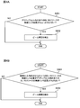
- FIGS. 4A and 4B are flowcharts showing an example of detection of beam impairment according to the second aspect.
- a user terminal may detect beam failure, when the radio link quality linked
- step S301 if the radio link quality associated with at least one DL-RS resource in the candidate set is greater than the radio link quality associated with all DL-RS resources in the active set (step S301; Yes), beam failure may be detected (step 302).
- At least one of the radio link qualities corresponding to the BLER of the virtual PDCCH transmitted by beams B21 to B23 is based on the radio link quality corresponding to the BLER of the virtual PDCCH transmitted by beams B11 to B13. If too large, beam impairment is detected.
- the beam failure since the beam failure is detected based on the control of the upper layer as well as the physical layer, the beam failure can be detected more appropriately.
- wireless communication system Hereinafter, the configuration of the radio communication system according to the present embodiment will be described.
- communication is performed using a combination of at least one of the above aspects.
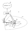
- FIG. 5 is a diagram showing an example of a schematic configuration of a wireless communication system according to the present embodiment.
- the radio communication system 1 applies carrier aggregation (CA) and / or dual connectivity (DC) in which a plurality of basic frequency blocks (component carriers) each having a system bandwidth (for example, 20 MHz) of the LTE system as one unit are integrated. can do.
- CA carrier aggregation
- DC dual connectivity
- the wireless communication system 1 includes LTE (Long Term Evolution), LTE-A (LTE-Advanced), LTE-B (LTE-Beyond), SUPER 3G, IMT-Advanced, 4G (4th generation mobile communication system), and 5G. It may be called (5th generation mobile communication system), NR (New Radio), FRA (Future Radio Access), New-RAT (Radio Access Technology) or the like, or may be called a system for realizing these.
- the radio communication system 1 includes a radio base station 11 forming a macrocell C1 with a relatively wide coverage, and radio base stations 12 (12a to 12c) disposed in the macrocell C1 and forming a small cell C2 narrower than the macrocell C1. And. Moreover, the user terminal 20 is arrange
- the user terminal 20 can be connected to both the radio base station 11 and the radio base station 12. It is assumed that the user terminal 20 simultaneously uses the macro cell C1 and the small cell C2 using CA or DC. Also, the user terminal 20 may apply CA or DC using a plurality of cells (CCs) (for example, 5 or less CCs, 6 or more CCs).
- CCs cells
- Communication can be performed between the user terminal 20 and the radio base station 11 using a relatively low frequency band (for example, 2 GHz) and a narrow bandwidth carrier (also called an existing carrier, legacy carrier, etc.).
- a carrier having a wide bandwidth in a relatively high frequency band for example, 3.5 GHz, 5 GHz, etc.
- the configuration of the frequency band used by each wireless base station is not limited to this.
- the user terminal 20 can perform communication in each cell using time division duplex (TDD) and / or frequency division duplex (FDD). Also, in each cell (carrier), a single numerology may be applied, or a plurality of different numerologies may be applied.
- TDD time division duplex
- FDD frequency division duplex
- Numerology may be communication parameters applied to transmission and / or reception of a certain signal and / or channel, for example, subcarrier spacing, bandwidth, symbol length, cyclic prefix length, subframe length , TTI length, number of symbols per TTI, radio frame configuration, filtering process, windowing process, etc. may be indicated.
- the wireless base station 11 and the wireless base station 12 are connected by wire (for example, an optical fiber conforming to CPRI (Common Public Radio Interface), X2 interface, etc.) or wirelessly It may be done.
- wire for example, an optical fiber conforming to CPRI (Common Public Radio Interface), X2 interface, etc.
- CPRI Common Public Radio Interface
- X2 interface etc.
- the radio base station 11 and each radio base station 12 are connected to the higher station apparatus 30 and connected to the core network 40 via the higher station apparatus 30.
- the upper station apparatus 30 includes, for example, an access gateway apparatus, a radio network controller (RNC), a mobility management entity (MME), and the like, but is not limited thereto. Further, each wireless base station 12 may be connected to the higher station apparatus 30 via the wireless base station 11.
- RNC radio network controller
- MME mobility management entity
- the radio base station 11 is a radio base station having a relatively wide coverage, and may be called a macro base station, an aggregation node, an eNB (eNodeB), a transmission / reception point, or the like.
- the radio base station 12 is a radio base station having local coverage, and is a small base station, a micro base station, a pico base station, a femto base station, a HeNB (Home eNodeB), an RRH (Remote Radio Head), transmission and reception It may be called a point or the like.
- the radio base stations 11 and 12 are not distinguished, they are collectively referred to as the radio base station 10.
- Each user terminal 20 is a terminal compatible with various communication schemes such as LTE and LTE-A, and may include not only mobile communication terminals (mobile stations) but also fixed communication terminals (fixed stations).
- orthogonal frequency division multiple access (OFDMA) is applied to the downlink as a radio access scheme, and single carrier frequency division multiple access (SC-FDMA: single carrier) to the uplink.
- SC-FDMA single carrier frequency division multiple access
- Frequency Division Multiple Access and / or OFDMA is applied.
- OFDMA is a multicarrier transmission scheme in which a frequency band is divided into a plurality of narrow frequency bands (subcarriers) and data is mapped to each subcarrier to perform communication.
- SC-FDMA is a single carrier transmission that reduces interference between terminals by dividing the system bandwidth into a band configured by one or continuous resource blocks for each terminal, and a plurality of terminals use different bands. It is a system.
- the uplink and downlink radio access schemes are not limited to these combinations, and other radio access schemes may be used.
- a downlink shared channel (PDSCH: Physical Downlink Shared Channel) shared by each user terminal 20, a broadcast channel (PBCH: Physical Broadcast Channel), a downlink L1 / L2 control channel, etc. are used as downlink channels. Used. User data, upper layer control information, SIB (System Information Block), etc. are transmitted by the PDSCH. Also, a MIB (Master Information Block) is transmitted by the PBCH.
- PDSCH Physical Downlink Shared Channel
- PBCH Physical Broadcast Channel
- SIB System Information Block
- MIB Master Information Block
- the downlink L1 / L2 control channel is a downlink control channel (PDCCH (Physical Downlink Control Channel) and / or EPDCCH (Enhanced Physical Downlink Control Channel)), PCFICH (Physical Control Format Indicator Channel), PHICH (Physical Hybrid-ARQ Indicator Channel)
- PDCCH Physical Downlink Control Channel
- DCI Downlink control information
- scheduling information may be notified by DCI.
- DCI scheduling DL data reception may be referred to as DL assignment
- DCI scheduling UL data transmission may be referred to as UL grant.
- the number of OFDM symbols used for PDCCH is transmitted by PCFICH.
- Delivery confirmation information (for example, also referred to as retransmission control information, HARQ-ACK, and ACK / NACK) of HARQ (Hybrid Automatic Repeat reQuest) for the PUSCH is transmitted by the PHICH.
- the EPDCCH is frequency division multiplexed with a PDSCH (downlink shared data channel), and is used for transmission such as DCI, similarly to the PDCCH.
- an uplink shared channel (PUSCH: Physical Uplink Shared Channel) shared by each user terminal 20, an uplink control channel (PUCCH: Physical Uplink Control Channel), a random access channel (PRACH: Physical Random Access Channel) or the like is used.
- User data, upper layer control information, etc. are transmitted by PUSCH.
- downlink radio link quality information (CQI: Channel Quality Indicator), delivery confirmation information, scheduling request (SR: Scheduling Request), etc. are transmitted by the PUCCH.
- the PRACH transmits a random access preamble for establishing a connection with a cell.
- a cell-specific reference signal (CRS: Cell-specific Reference Signal), a channel state information reference signal (CSI-RS: Channel State Information-Reference Signal), a demodulation reference signal (DMRS: DeModulation Reference Signal, positioning reference signal (PRS), etc.
- CRS Cell-specific Reference Signal
- CSI-RS Channel State Information-Reference Signal
- DMRS DeModulation Reference Signal
- PRS positioning reference signal
- SRS Sounding Reference Signal
- DMRS demodulation reference signal
- PRS positioning reference signal
- DMRS Demodulation reference signal
- PRS positioning reference signal
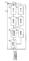
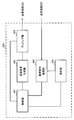
- FIG. 6 is a diagram showing an example of the entire configuration of the radio base station according to the present embodiment.
- the radio base station 10 includes a plurality of transmitting and receiving antennas 101, an amplifier unit 102, a transmitting and receiving unit 103, a baseband signal processing unit 104, a call processing unit 105, and a transmission path interface 106. Note that each of the transmitting and receiving antenna 101, the amplifier unit 102, and the transmitting and receiving unit 103 may be configured to include one or more.
- User data transmitted from the radio base station 10 to the user terminal 20 by downlink is input from the higher station apparatus 30 to the baseband signal processing unit 104 via the transmission path interface 106.
- the baseband signal processing unit 104 performs packet data convergence protocol (PDCP) layer processing, user data division / combination, RLC layer transmission processing such as RLC (Radio Link Control) retransmission control, and MAC (Medium Access) for user data.
- Control Transmission processing such as retransmission control (for example, HARQ transmission processing), scheduling, transmission format selection, channel coding, inverse fast Fourier transform (IFFT) processing, precoding processing, etc. It is transferred to 103. Further, transmission processing such as channel coding and inverse fast Fourier transform is also performed on the downlink control signal and transferred to the transmission / reception unit 103.
- the transmission / reception unit 103 converts the baseband signal output from the baseband signal processing unit 104 for each antenna into a radio frequency band and transmits the baseband signal.
- the radio frequency signal frequency-converted by the transmitting and receiving unit 103 is amplified by the amplifier unit 102 and transmitted from the transmitting and receiving antenna 101.
- the transmission / reception unit 103 can be configured of a transmitter / receiver, a transmission / reception circuit, or a transmission / reception device described based on the common recognition in the technical field according to the present disclosure.
- the transmitting and receiving unit 103 may be configured as an integrated transmitting and receiving unit, or may be configured from a transmitting unit and a receiving unit.
- the radio frequency signal received by the transmission / reception antenna 101 is amplified by the amplifier unit 102.
- the transmitting and receiving unit 103 receives the upstream signal amplified by the amplifier unit 102.
- the transmission / reception unit 103 frequency-converts the received signal into a baseband signal and outputs the result to the baseband signal processing unit 104.
- the baseband signal processing unit 104 performs Fast Fourier Transform (FFT) processing, Inverse Discrete Fourier Transform (IDFT) processing, and error correction on user data included in the input upstream signal. Decoding, reception processing of MAC retransmission control, and reception processing of RLC layer and PDCP layer are performed, and are transferred to the higher station apparatus 30 via the transmission path interface 106.
- the call processing unit 105 performs call processing (setting, release, etc.) of the communication channel, state management of the radio base station 10, management of radio resources, and the like.
- the transmission path interface 106 transmits and receives signals to and from the higher station apparatus 30 via a predetermined interface. Also, the transmission path interface 106 transmits / receives signals (backhaul signaling) to / from the other wireless base station 10 via an inter-base station interface (for example, an optical fiber conforming to CPRI (Common Public Radio Interface), X2 interface). May be
- an inter-base station interface for example, an optical fiber conforming to CPRI (Common Public Radio Interface), X2 interface.
- the transmitting and receiving unit 103 may further include an analog beam forming unit that performs analog beam forming.
- the analog beamforming unit comprises an analog beamforming circuit (eg, phase shifter, phase shift circuit) or an analog beamforming apparatus (eg, phase shifter) described based on common recognition in the technical field according to the present invention can do.
- the transmitting and receiving antenna 101 can be configured by, for example, an array antenna. Further, the transmission / reception unit 103 is configured to be able to apply single BF and multi BF.
- the transmission / reception unit 103 may transmit a signal using a transmission beam, or may receive a signal using a reception beam.
- the transmitting and receiving unit 103 may transmit and / or receive a signal using a predetermined beam determined by the control unit 301.
- the transmitting and receiving unit 103 may receive the various information described in the above respective aspects from the user terminal 20 and / or transmit the various information to the user terminal 20.
- the transmission / reception unit 103 may use the first and second virtual PDCCH information, information indicating the configuration of DL-RS resources for measurement (for example, CSI-RS resources and / or SS / PBCH blocks), DMRS port, and CSI- Send at least one of the information indicating the association of RS.
- the transceiver unit 103 may transmit configuration information on radio link failure (RLF) and / or beam recovery (BR).
- RLF radio link failure
- BR beam recovery
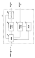
- FIG. 7 is a diagram showing an example of a functional configuration of the radio base station according to the present embodiment.
- the functional block of the characteristic part in this Embodiment is mainly shown, and it may be assumed that the wireless base station 10 also has another functional block required for wireless communication.
- the baseband signal processing unit 104 at least includes a control unit (scheduler) 301, a transmission signal generation unit 302, a mapping unit 303, a reception signal processing unit 304, and a measurement unit 305. Note that these configurations may be included in the wireless base station 10, and some or all of the configurations may not be included in the baseband signal processing unit 104.
- a control unit (scheduler) 301 performs control of the entire radio base station 10.
- the control unit 301 can be configured of a controller, a control circuit, or a control device described based on the common recognition in the technical field according to the present disclosure.
- the control unit 301 controls, for example, generation of a signal in the transmission signal generation unit 302, assignment of a signal in the mapping unit 303, and the like. Further, the control unit 301 controls reception processing of a signal in the reception signal processing unit 304, measurement of a signal in the measurement unit 305, and the like.
- the control unit 301 schedules (for example, resources) system information, downlink data signals (for example, signals transmitted on PDSCH), downlink control signals (for example, signals transmitted on PDCCH and / or EPDCCH, delivery confirmation information, etc.) Control allocation). Further, the control unit 301 controls generation of the downlink control signal, the downlink data signal, and the like based on the result of determining whether the retransmission control for the uplink data signal is necessary or not.
- the control unit 301 controls scheduling of synchronization signals (for example, PSS / SSS), downlink reference signals (for example, CRS, CSI-RS, DMRS) and the like.
- synchronization signals for example, PSS / SSS
- downlink reference signals for example, CRS, CSI-RS, DMRS
- the control unit 301 performs control of forming a transmission beam and / or a reception beam by using the digital BF (for example, precoding) by the baseband signal processing unit 104 and / or the analog BF (for example, phase rotation) by the transmission / reception unit 103.
- the control unit 301 may control the setting of RLF and / or BR based on configuration information on radio link failure (RLF) and / or beam recovery (BR).
- the control unit 301 may control detection of a beam failure in the BR based on the relationship between the RLF and the BR.
- the control unit 301 may control radio link monitoring (RLM) and / or beam recovery (BR) for the user terminal 20.
- RLM radio link monitoring
- BR beam recovery
- the control unit 301 controls generation and / or transmission of information (virtual PDCCH information) related to a virtual PDCCH (downlink control channel).
- Virtual PDCCH information includes information indicating a specific control resource set, information indicating a specific aggregation level, information indicating a format of downlink control information, information indicating a demodulation reference signal pattern, and information indicating the predetermined block error rate. And at least one of
- the transmission signal generation unit 302 generates a downlink signal (downlink control signal, downlink data signal, downlink reference signal or the like) based on an instruction from the control unit 301, and outputs the downlink signal to the mapping unit 303.
- the transmission signal generation unit 302 can be configured from a signal generator, a signal generation circuit, or a signal generation device described based on the common recognition in the technical field according to the present disclosure.
- the transmission signal generation unit 302 generates, for example, DL assignment for notifying downlink data allocation information and / or UL grant for notifying uplink data allocation information, based on an instruction from the control unit 301.
- DL assignment and UL grant are both DCI and follow DCI format.
- coding processing, modulation processing, and the like are performed on the downlink data signal according to a coding rate, a modulation method, and the like determined based on channel state information (CSI: Channel State Information) and the like from each user terminal 20.
- CSI Channel State Information
- Mapping section 303 maps the downlink signal generated by transmission signal generation section 302 to a predetermined radio resource based on an instruction from control section 301, and outputs the mapped downlink signal to transmission / reception section 103.
- the mapping unit 303 can be configured from a mapper, a mapping circuit or a mapping device described based on the common recognition in the technical field according to the present disclosure.
- the reception signal processing unit 304 performs reception processing (for example, demapping, demodulation, decoding, and the like) on the reception signal input from the transmission / reception unit 103.
- the reception signal is, for example, an uplink signal (uplink control signal, uplink data signal, uplink reference signal, etc.) transmitted from the user terminal 20.
- the received signal processing unit 304 can be configured from a signal processor, a signal processing circuit or a signal processing device described based on the common recognition in the technical field according to the present disclosure.
- the reception signal processing unit 304 outputs the information decoded by the reception process to the control unit 301. For example, when the PUCCH including the HARQ-ACK is received, the HARQ-ACK is output to the control unit 301. Further, the reception signal processing unit 304 outputs the reception signal and / or the signal after reception processing to the measurement unit 305.
- the measurement unit 305 performs measurement on the received signal.
- the measuring unit 305 can be configured from a measuring device, a measuring circuit, or a measuring device described based on the common recognition in the technical field according to the present disclosure.
- the measurement unit 305 may perform Radio Resource Management (RRM) measurement, Channel State Information (CSI) measurement, and the like based on the received signal.
- the measurement unit 305 may use received power (for example, reference signal received power (RSRP)), received quality (for example, reference signal received quality (RSRQ), signal to interference plus noise ratio (SINR), signal to noise ratio (SNR)). , Signal strength (e.g., received signal strength indicator (RSSI)), channel information (e.g., CSI), and the like.
- RSRP reference signal received power
- RSSI received signal strength indicator
- CSI channel information
- the measurement result may be output to the control unit 301.
- FIG. 8 is a diagram showing an example of the entire configuration of the user terminal according to the present embodiment.
- the user terminal 20 includes a plurality of transmitting and receiving antennas 201, an amplifier unit 202, a transmitting and receiving unit 203, a baseband signal processing unit 204, and an application unit 205.
- each of the transmitting and receiving antenna 201, the amplifier unit 202, and the transmitting and receiving unit 203 may be configured to include one or more.
- the radio frequency signal received by the transmission / reception antenna 201 is amplified by the amplifier unit 202.
- the transmitting and receiving unit 203 receives the downlink signal amplified by the amplifier unit 202.
- the transmission / reception unit 203 frequency-converts the received signal into a baseband signal and outputs the result to the baseband signal processing unit 204.
- the transmission / reception unit 203 can be configured of a transmitter / receiver, a transmission / reception circuit, or a transmission / reception device described based on the common recognition in the technical field according to the present disclosure.
- the transmission / reception unit 203 may be configured as an integrated transmission / reception unit, or may be configured from a transmission unit and a reception unit.
- the baseband signal processing unit 204 performs reception processing of FFT processing, error correction decoding, retransmission control, and the like on the input baseband signal.
- the downlink user data is transferred to the application unit 205.
- the application unit 205 performs processing on a layer higher than the physical layer and the MAC layer. Moreover, broadcast information may also be transferred to the application unit 205 among downlink data.
- uplink user data is input from the application unit 205 to the baseband signal processing unit 204.
- the baseband signal processing unit 204 performs transmission processing of retransmission control (for example, transmission processing of HARQ), channel coding, precoding, discrete Fourier transform (DFT) processing, IFFT processing, etc. It is transferred to 203.
- the transmission / reception unit 203 converts the baseband signal output from the baseband signal processing unit 204 into a radio frequency band and transmits it.
- the radio frequency signal frequency-converted by the transmitting and receiving unit 203 is amplified by the amplifier unit 202 and transmitted from the transmitting and receiving antenna 201.
- the transmitting and receiving unit 203 may further include an analog beam forming unit that performs analog beam forming.
- the analog beamforming unit comprises an analog beamforming circuit (eg, phase shifter, phase shift circuit) or an analog beamforming apparatus (eg, phase shifter) described based on common recognition in the technical field according to the present invention can do.
- the transmitting and receiving antenna 201 can be configured by, for example, an array antenna.
- the transmission / reception unit 203 is configured to be able to apply single BF and multi BF.
- the transmission / reception unit 203 may transmit a signal using a transmission beam, or may receive a signal using a reception beam.
- the transmitting and receiving unit 203 may transmit and / or receive a signal using a predetermined beam determined by the control unit 401.
- the transmitting and receiving unit 203 may receive the various information described in the above respective aspects from the wireless base station 10 and / or transmit the various information to the wireless base station 10.
- the transmission / reception unit 203 may use the first and second virtual PDCCH information, information indicating the configuration of DL-RS resources for measurement (for example, CSI-RS resources and / or SS / PBCH blocks), DMRS port, and CSI- At least one of the information indicating the association of RS may be transmitted.
- the transceiver unit 203 may receive configuration information regarding radio link failure (RLF) and / or beam recovery (BR).
- RLF radio link failure
- BR beam recovery
- FIG. 9 is a diagram showing an example of a functional configuration of the user terminal according to the present embodiment.
- the functional block of the characteristic part in this Embodiment is mainly shown, and it may be assumed that the user terminal 20 also has another functional block required for wireless communication.
- the baseband signal processing unit 204 included in the user terminal 20 at least includes a control unit 401, a transmission signal generation unit 402, a mapping unit 403, a reception signal processing unit 404, and a measurement unit 405. Note that these configurations may be included in the user terminal 20, and some or all of the configurations may not be included in the baseband signal processing unit 204.
- the control unit 401 controls the entire user terminal 20.
- the control unit 401 can be configured of a controller, a control circuit, or a control device described based on the common recognition in the technical field according to the present disclosure.
- the control unit 401 controls, for example, generation of a signal in the transmission signal generation unit 402, assignment of a signal in the mapping unit 403, and the like. Further, the control unit 401 controls reception processing of signals in the reception signal processing unit 404, measurement of signals in the measurement unit 405, and the like.
- the control unit 401 acquires the downlink control signal and the downlink data signal transmitted from the radio base station 10 from the reception signal processing unit 404.
- the control unit 401 controls the generation of the uplink control signal and / or the uplink data signal based on the result of determining the necessity of the retransmission control for the downlink control signal and / or the downlink data signal.
- the control unit 401 performs control of forming a transmission beam and / or a reception beam using digital BF (for example, precoding) by the baseband signal processing unit 204 and / or analog BF (for example, phase rotation) by the transmission / reception unit 203.
- digital BF for example, precoding
- analog BF for example, phase rotation
- the control unit 401 may control radio link monitoring (RLM) and / or beam recovery (BR) based on the measurement result of the measurement unit 405.
- RLM radio link monitoring
- BR beam recovery
- the control unit 401 determines, based on the virtual PDCCH information notified from the radio base station 10, the radio link quality of the downlink signal of the first set (active set) where pseudo colocation with the DMRS of the PDCCH is assumed, and / or The radio link quality monitoring (RLM) of the downlink signal of the second set (candidate set) set by the radio base station 10 may be controlled.
- the downlink signal may be a CSI-RS (resource) and / or an SS / PBCH block.
- Controller 401 may determine a first threshold value Q out_1 and / or the second threshold value Q IN_1 corresponding to the predetermined block error rate of the virtual downlink control channel based on the virtual PDCCH information (first Aspect of
- Controller 401 may determine a third threshold Q OUT_2 and / or fourth threshold value Q IN_2 corresponding to the downlink control channel predetermined block error rate of the virtual based on the virtual PDCCH information (first Aspect).
- the control unit 401 performs beam failure based on at least one of the first threshold Q out_1 , the radio link quality of the downlink signal in the first set, and the radio link quality of the downlink signal in the second set. Control the detection of ( Figure 4).
- the control unit 401 may control the setting of RLF and / or BR based on configuration information on radio link failure (RLF) and / or beam recovery (BR).
- the control unit 401 may control detection of a beam failure in the BR based on the relationship between the RLF and the BR.
- control unit 401 When the control unit 401 acquires various types of information notified from the radio base station 10 from the received signal processing unit 404, the control unit 401 may update parameters used for control based on the information.
- the transmission signal generation unit 402 generates an uplink signal (uplink control signal, uplink data signal, uplink reference signal or the like) based on an instruction from the control unit 401, and outputs the uplink signal to the mapping unit 403.
- the transmission signal generation unit 402 can be configured from a signal generator, a signal generation circuit or a signal generation device described based on the common recognition in the technical field according to the present disclosure.
- the transmission signal generation unit 402 generates, for example, an uplink control signal related to delivery confirmation information, channel state information (CSI), and the like based on an instruction from the control unit 401. Further, the transmission signal generation unit 402 generates an uplink data signal based on an instruction from the control unit 401. For example, when the downlink control signal notified from the radio base station 10 includes a UL grant, the transmission signal generation unit 402 is instructed by the control unit 401 to generate an uplink data signal.
- CSI channel state information
- Mapping section 403 maps the uplink signal generated by transmission signal generation section 402 to a radio resource based on an instruction from control section 401, and outputs the uplink signal to transmission / reception section 203.
- the mapping unit 403 can be configured from a mapper, a mapping circuit, or a mapping device described based on the common recognition in the technical field according to the present disclosure.
- the reception signal processing unit 404 performs reception processing (for example, demapping, demodulation, decoding, and the like) on the reception signal input from the transmission / reception unit 203.
- the reception signal is, for example, a downlink signal (a downlink control signal, a downlink data signal, a downlink reference signal, or the like) transmitted from the radio base station 10.
- the received signal processing unit 404 can be configured from a signal processor, a signal processing circuit or a signal processing device described based on the common recognition in the technical field according to the present disclosure. Further, the received signal processing unit 404 can configure a receiving unit according to the present disclosure.
- the reception signal processing unit 404 outputs the information decoded by the reception process to the control unit 401.
- the received signal processing unit 404 outputs, for example, broadcast information, system information, RRC signaling, DCI, and the like to the control unit 401. Further, the reception signal processing unit 404 outputs the reception signal and / or the signal after reception processing to the measurement unit 405.
- the measurement unit 405 performs measurement on the received signal.
- the measuring unit 405 can be configured from a measuring device, a measuring circuit, or a measuring device described based on the common recognition in the technical field according to the present disclosure.
- the measurement unit 405 may perform RRM measurement, CSI measurement, and the like based on the received signal.
- the measurement unit 405 may measure reception power (for example, RSRP), reception quality (for example, RSRQ, SINR, SNR), signal strength (for example, RSSI), channel information (for example, CSI), and the like.
- the measurement result may be output to the control unit 401.
- each functional block may be realized using one physically and / or logically coupled device, or directly and / or two or more physically and / or logically separated devices. Or it may connect indirectly (for example, using a wire communication and / or radio), and it may be realized using a plurality of these devices.
- the radio base station, the user terminal, and the like in the present embodiment may function as a computer that performs the processing of each aspect of the present embodiment.
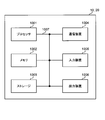
- FIG. 10 is a diagram showing an example of the hardware configuration of the radio base station and the user terminal according to the present embodiment.
- the above-described wireless base station 10 and user terminal 20 may be physically configured as a computer device including a processor 1001, a memory 1002, a storage 1003, a communication device 1004, an input device 1005, an output device 1006, a bus 1007 and the like. Good.
- the term “device” can be read as a circuit, a device, a unit, or the like.
- the hardware configuration of the radio base station 10 and the user terminal 20 may be configured to include one or more of the devices illustrated in the figure, or may be configured without including some devices.
- processor 1001 may be implemented by one or more chips.
- Each function in the radio base station 10 and the user terminal 20 is calculated by causing the processor 1001 to read predetermined software (program) on hardware such as the processor 1001 and the memory 1002, and the communication device 1004 is performed. This is realized by controlling communication, and controlling reading and / or writing of data in the memory 1002 and the storage 1003.
- the processor 1001 operates, for example, an operating system to control the entire computer.
- the processor 1001 may be configured by a central processing unit (CPU) including an interface with a peripheral device, a control device, an arithmetic device, a register, and the like.
- CPU central processing unit
- the above-described baseband signal processing unit 104 (204), call processing unit 105, and the like may be realized by the processor 1001.
- the processor 1001 reads a program (program code), a software module, data, and the like from the storage 1003 and / or the communication device 1004 to the memory 1002, and executes various processing according to these.
- a program a program that causes a computer to execute at least a part of the operation described in the above-described embodiment is used.
- the control unit 401 of the user terminal 20 may be realized by a control program stored in the memory 1002 and operating in the processor 1001, or may be realized similarly for other functional blocks.
- the memory 1002 is a computer readable recording medium, and for example, at least at least a read only memory (ROM), an erasable programmable ROM (EPROM), an electrically EPROM (EEPROM), a random access memory (RAM), or any other suitable storage medium. It may be configured by one.
- the memory 1002 may be called a register, a cache, a main memory (main storage device) or the like.
- the memory 1002 can store a program (program code), a software module, and the like that can be executed to implement the wireless communication method according to the present embodiment.
- the storage 1003 is a computer readable recording medium, and for example, a flexible disk, a floppy (registered trademark) disk, a magneto-optical disk (for example, a compact disk (CD-ROM (Compact Disc ROM), etc.), a digital versatile disk, Blu-ray® disc), removable disc, hard disc drive, smart card, flash memory device (eg card, stick, key drive), magnetic stripe, database, server, at least one other suitable storage medium May be configured by The storage 1003 may be called an auxiliary storage device.
- a computer readable recording medium for example, a flexible disk, a floppy (registered trademark) disk, a magneto-optical disk (for example, a compact disk (CD-ROM (Compact Disc ROM), etc.), a digital versatile disk, Blu-ray® disc), removable disc, hard disc drive, smart card, flash memory device (eg card, stick, key drive), magnetic stripe, database, server, at least one other suitable storage medium May be configured by
- the communication device 1004 is hardware (transmission / reception device) for performing communication between computers via a wired and / or wireless network, and is also called, for example, a network device, a network controller, a network card, a communication module, or the like.
- the communication device 1004 includes, for example, a high frequency switch, a duplexer, a filter, a frequency synthesizer, and the like to realize, for example, frequency division duplex (FDD) and / or time division duplex (TDD). It may be configured.
- FDD frequency division duplex
- TDD time division duplex
- the transmission / reception antenna 101 (201), the amplifier unit 102 (202), the transmission / reception unit 103 (203), the transmission path interface 106, and the like described above may be realized by the communication device 1004.
- the input device 1005 is an input device (for example, a keyboard, a mouse, a microphone, a switch, a button, a sensor, and the like) that receives an input from the outside.
- the output device 1006 is an output device (for example, a display, a speaker, a light emitting diode (LED) lamp, and the like) that performs output to the outside.
- the input device 1005 and the output device 1006 may be integrated (for example, a touch panel).
- each device such as the processor 1001 and the memory 1002 is connected by a bus 1007 for communicating information.
- the bus 1007 may be configured using a single bus, or may be configured using different buses between devices.
- radio base station 10 and the user terminal 20 may be microprocessors, digital signal processors (DSPs), application specific integrated circuits (ASICs), programmable logic devices (PLDs), field programmable gate arrays (FPGAs), etc.
- DSPs digital signal processors
- ASICs application specific integrated circuits
- PLDs programmable logic devices
- FPGAs field programmable gate arrays
- Hardware may be included, and part or all of each functional block may be realized using the hardware.
- processor 1001 may be implemented using at least one of these hardware.
- the channels and / or symbols may be signaling.
- the signal may be a message.
- the reference signal may be abbreviated as RS (Reference Signal), and may be referred to as a pilot (Pilot), a pilot signal or the like according to an applied standard.
- a component carrier CC: Component Carrier
- CC Component Carrier
- the radio frame may be configured by one or more periods (frames) in the time domain.
- Each of the one or more periods (frames) that constitute a radio frame may be referred to as a subframe.
- a subframe may be configured by one or more slots in the time domain.
- the subframes may be of a fixed time length (e.g., 1 ms) independent of the neurology.
- the slot may be configured by one or more symbols in the time domain (such as orthogonal frequency division multiplexing (OFDM) symbols, single carrier frequency division multiple access (SC-FDMA) symbols, etc.).
- the slot may be a time unit based on the neurology.
- the slot may include a plurality of minislots. Each minislot may be configured by one or more symbols in the time domain. Minislots may also be referred to as subslots.
- a radio frame, a subframe, a slot, a minislot and a symbol all represent time units when transmitting a signal.
- subframes, slots, minislots and symbols other names corresponding to each may be used.
- one subframe may be referred to as a transmission time interval (TTI)
- TTI transmission time interval
- a plurality of consecutive subframes may be referred to as a TTI
- one slot or one minislot may be referred to as a TTI.
- TTI transmission time interval
- the subframe and / or TTI may be a subframe (1 ms) in existing LTE, a period shorter than 1 ms (eg, 1-13 symbols), or a period longer than 1 ms. It may be.
- the unit representing TTI may be called a slot, a minislot, etc. instead of a subframe.
- TTI refers to, for example, the minimum time unit of scheduling in wireless communication.
- the radio base station performs scheduling to assign radio resources (frequency bandwidth usable in each user terminal, transmission power, etc.) to each user terminal in TTI units.
- radio resources frequency bandwidth usable in each user terminal, transmission power, etc.
- the TTI may be a transmission time unit of a channel encoded data packet (transport block), a code block, and / or a codeword, or may be a processing unit such as scheduling and link adaptation. Note that, when a TTI is given, the time interval (eg, the number of symbols) in which the transport block, the code block, and / or the codeword is actually mapped may be shorter than the TTI.
- one or more TTIs may be the minimum time unit of scheduling.
- the number of slots (the number of minislots) constituting the minimum time unit of the scheduling may be controlled.
- a TTI having a time length of 1 ms may be referred to as a normal TTI (TTI in LTE Rel. 8-12), a normal TTI, a long TTI, a normal subframe, a normal subframe, a long subframe, or the like.
- a TTI shorter than a normal TTI may be referred to as a shortened TTI, a short TTI, a partial TTI (partial or fractional TTI), a shortened subframe, a short subframe, a minislot, a subslot, or the like.
- a long TTI for example, a normal TTI, a subframe, etc.
- a short TTI eg, a shortened TTI, etc.
- a resource block is a resource allocation unit in time domain and frequency domain, and may include one or more consecutive subcarriers (subcarriers) in the frequency domain. Also, an RB may include one or more symbols in the time domain, and may be one slot, one minislot, one subframe, or one TTI in length. One TTI and one subframe may be respectively configured by one or more resource blocks. Note that one or more RBs may be a physical resource block (PRB: Physical RB), a subcarrier group (SCG: Sub-Carrier Group), a resource element group (REG: Resource Element Group), a PRB pair, an RB pair, etc. It may be called.
- PRB Physical resource block
- SCG Sub-Carrier Group
- REG Resource Element Group
- a resource block may be configured by one or more resource elements (RE: Resource Element).
- RE Resource Element
- one RE may be one subcarrier and one symbol radio resource region.
- the above-described structures such as the radio frame, subframe, slot, minislot and symbol are merely examples.
- the number of subframes included in a radio frame the number of slots per subframe or radio frame, the number of minislots included in a slot, the number of symbols and RBs included in a slot or minislot, included in an RB
- the number of subcarriers, as well as the number of symbols in a TTI, the symbol length, the cyclic prefix (CP) length, and other configurations can be variously changed.
- the information, parameters, etc. described in the present specification may be expressed using absolute values, may be expressed using relative values from predetermined values, or other corresponding information. May be represented.
- radio resources may be indicated by a predetermined index.
- the names used for parameters and the like in the present specification are not limited names in any respect.
- various channels PUCCH (Physical Uplink Control Channel), PDCCH (Physical Downlink Control Channel), etc.
- information elements can be identified by any suitable names, various assignments are made to these various channels and information elements.
- the name is not limited in any way.
- data, instructions, commands, information, signals, bits, symbols, chips etc may be voltage, current, electromagnetic waves, magnetic fields or particles, optical fields or photons, or any of these May be represented by a combination of
- information, signals, etc. may be output from the upper layer to the lower layer and / or from the lower layer to the upper layer.
- Information, signals, etc. may be input / output via a plurality of network nodes.
- the input / output information, signals and the like may be stored in a specific place (for example, a memory) or may be managed using a management table. Information, signals, etc. input and output can be overwritten, updated or added. The output information, signals and the like may be deleted. The input information, signals and the like may be transmitted to other devices.
- notification of information is not limited to the aspect / embodiment described herein, and may be performed using other methods.
- notification of information may be physical layer signaling (eg, downlink control information (DCI), uplink control information (UCI)), upper layer signaling (eg, RRC (Radio Resource Control) signaling, It may be implemented by broadcast information (Master Information Block (MIB), System Information Block (SIB), etc.), MAC (Medium Access Control) signaling, other signals, or a combination thereof.
- DCI downlink control information
- UCI uplink control information
- RRC Radio Resource Control
- MIB Master Information Block
- SIB System Information Block
- MAC Medium Access Control
- the physical layer signaling may be called L1 / L2 (Layer 1 / Layer 2) control information (L1 / L2 control signal), L1 control information (L1 control signal), or the like.
- RRC signaling may be referred to as an RRC message, and may be, for example, an RRC connection setup (RRC Connection Setup) message, an RRC connection reconfiguration (RRC Connection Reconfiguration) message, or the like.
- MAC signaling may be notified using, for example, a MAC control element (MAC CE (Control Element)).
- notification of predetermined information is not limited to explicit notification, but implicitly (for example, by not notifying the predetermined information or other information Notification may be performed).
- the determination may be performed by a value (0 or 1) represented by one bit, or may be performed by a boolean value represented by true or false. , Numerical comparison (for example, comparison with a predetermined value) may be performed.
- Software may be called software, firmware, middleware, microcode, hardware description language, or any other name, and may be instructions, instruction sets, codes, code segments, program codes, programs, subprograms, software modules. Should be interpreted broadly to mean applications, software applications, software packages, routines, subroutines, objects, executables, threads of execution, procedures, functions, etc.
- software, instructions, information, etc. may be sent and received via a transmission medium.
- software may use a wired technology (coaxial cable, fiber optic cable, twisted pair, digital subscriber line (DSL), etc.) and / or a wireless technology (infrared, microwave, etc.), a website, a server
- wired technology coaxial cable, fiber optic cable, twisted pair, digital subscriber line (DSL), etc.
- wireless technology infrared, microwave, etc.
- system and "network” as used herein are used interchangeably.
- base station Base Station
- radio base station eNB
- gNB gigad Generation
- cell cell
- cell group cell group
- carrier carrier
- carrier may be used interchangeably.
- a base station may also be called in terms of a fixed station (Node station), NodeB, eNodeB (eNB), access point (access point), transmission point, reception point, femtocell, small cell, and so on.
- a base station may accommodate one or more (e.g., three) cells (also called sectors). If the base station accommodates multiple cells, the entire coverage area of the base station can be partitioned into multiple smaller areas, each smaller area being a base station subsystem (eg, a small base station for indoor use (RRH: Communication service can also be provided by Remote Radio Head).
- RRH Communication service can also be provided by Remote Radio Head.
- the terms "cell” or “sector” refer to part or all of the coverage area of a base station and / or a base station subsystem serving communication services in this coverage.
- MS mobile station
- UE user equipment
- the mobile station may be a subscriber station, a mobile unit, a subscriber unit, a wireless unit, a remote unit, a mobile device, a wireless device, a wireless communication device, a remote device, a mobile subscriber station, an access terminal, a mobile terminal, a wireless terminal, by those skilled in the art. It may also be called a terminal, a remote terminal, a handset, a user agent, a mobile client, a client or some other suitable term.
- the radio base station in the present specification may be replaced with a user terminal.
- each aspect / this embodiment of the present disclosure is applied to a configuration in which communication between a wireless base station and a user terminal is replaced with communication between a plurality of user terminals (D2D: Device-to-Device).
- the user terminal 20 may have a function that the above-described radio base station 10 has.
- the wordings such as "up” and “down” may be read as "side".
- the upstream channel may be read as a side channel.
- a user terminal herein may be read at a radio base station.
- the radio base station 10 may have a function that the above-described user terminal 20 has.
- the operation supposed to be performed by the base station may be performed by its upper node in some cases.
- various operations performed for communication with a terminal may be a base station, one or more network nodes other than the base station (eg, It is apparent that this can be performed by MME (Mobility Management Entity), S-GW (Serving-Gateway), etc. but not limited thereto or a combination thereof.
- MME Mobility Management Entity
- S-GW Serving-Gateway
- Each aspect / embodiment described in the present specification is LTE (Long Term Evolution), LTE-A (LTE-Advanced), LTE-B (LTE-Beyond), SUPER 3G, IMT-Advanced, 4G (4th (4th) Generation mobile communication system (5G), 5th generation mobile communication system (5G), Future Radio Access (FRA), Radio Access Technology (New RAT), New Radio (NR), New radio access (NX), Future generation radio access (FX) ), GSM (registered trademark) (Global System for Mobile communications), CDMA2000, UMB (Ultra Mobile Broadband), IEEE 802.11 (Wi-Fi (registered trademark)), IEEE 802.16 (WiMAX (registered trademark)), IEEE 802.20, UWB (Ultra-Wide Band), Bluetooth (Registration The present invention may be applied to a system using a trademark, another appropriate wireless communication method, and / or an advanced next-generation system based on these.
- 5G Fifth Generation mobile communication system
- 5G 5th generation mobile communication system
- any reference to an element using the designation "first”, “second” and the like as used herein does not generally limit the quantity or order of those elements. These designations may be used herein as a convenient way of distinguishing between two or more elements. Thus, reference to the first and second elements does not mean that only two elements can be taken or that the first element must somehow precede the second element.
- determining may encompass a wide variety of operations. For example, “determination” may be calculating, computing, processing, deriving, investigating, looking up (eg, table, database or other data) A search on structure), ascertaining, etc. may be considered as “determining”. Also, “determination” may be receiving (e.g. receiving information), transmitting (e.g. transmitting information), input (input), output (output), access (access) It may be considered as “determining” (eg, accessing data in memory) and the like. Also, “determination” is considered to be “determination” to resolve, select, choose, choose, establish, compare, etc. It is also good. That is, “determination” may be considered as “determining” some action.
- connection refers to any direct or indirect connection between two or more elements or It means a bond and can include the presence of one or more intermediate elements between two elements “connected” or “connected” to each other.
- the coupling or connection between elements may be physical, logical or a combination thereof. For example, “connection” may be read as "access”.
- the radio frequency domain It can be considered as “connected” or “coupled” with one another using electromagnetic energy or the like having wavelengths in the microwave region and / or the light (both visible and invisible) regions.
- a and B are different may mean “A and B are different from each other”.
- the terms “leave”, “combined” and the like may be interpreted similarly.
- the recovery mechanism for UE beam failure includes the following aspects: ⁇ Beam failure detection (Beam failure detection) ⁇ New candidate beam identification ⁇ Beam failure recovery request transmission (Beam failure recovery request transmission) Detection of beam failure UE monitors gNB response to beam failure recovery request (UE monitors gNB response for beam failure recovery request).
- beam failure recovery may be called recovery from beam failure, beam recovery (BR: beam recovery) or the like.
- Beam failure is only declared when all serving control channels fail. • It may also be treated as a beam failure when the serving control channel subset fails.
- the UE sends higher notification to the upper layer (for example, beam failure recovery indication) and suppresses further beam failure recovery .
- Associate Radio Link Failure (RLF) and the above specific notification (if any). For example, it defines whether the beam failure recovery procedure affects RLF events, is affected by RLF events, etc.
- the UE should monitor the beam management reference signal to judge whether the Physical Downlink Control Channel (PDCCH) can be detected or not.
- the beam management reference signal may be, for example, a channel state information reference signal (CSI-RS), a synchronization signal block (SSB), or the like.
- CSI-RS channel state information reference signal
- SSB synchronization signal block
- -The CORESET of each PDCCH is configured (and / or associated) with one RS resource by gNB.
- the UE is associated with each CORESET in order to estimate the PDCCH channel quality based on certain criteria or to determine if the Beam Pair Link (BPL) has failed Measure RS resources.
- BPL Beam Pair Link
- the first option is the hypothetical performance of PDCCH (NR-PDCCH), which is similar to that of radio link monitoring (RLM: Radio Link Monitoring) in existing LTE, in synchronization state (IS: In- It is evaluated based on Sync) and out-of-sync (OOS).
- the determination of the IS / OOS may be performed based on, for example, a Signal to Interference plus Noise Ratio (SINR) corresponding to a block error rate (BLER) of a virtual PDCCH.
- SINR Signal to Interference plus Noise Ratio
- the second option is L1-RSRP (Reference Signal Received Power (RSRP) in the physical layer) based metric.
- RSRP Reference Signal Received Power
- Parameters for evaluation such as threshold values, evaluation time windows (periods), etc. can be set.
- the advantages and disadvantages of the existing proposals for these metrics are:
- the first option is similar to and / or more like the control of RLF. Consistent metrics are used for beam impairment assessment and RLF.
- RSRP is not a direct criterion of control channel quality. Also, RSRP takes a long time to filter to ensure that it is not affected by fading dip.
- the second option is similar and / or more like control of beam management. Consistent metrics are used for beam impairment assessment and beam management. As the origin of beam recovery is to deal with blockage (e.g. blockage by obstacles), it is well represented by the RSRP of the signal and / or channel. If the beam change in adjacent cells is fast, the change in interferometric measurement is also fast. In such a case, it takes a relatively long time to obtain stable results and is not suitable for L1. The complexity of the UE can be reduced since no noise and / or interference estimation (measurement) is required.
- RLF and beam recovery Support the case where RLF and beam recovery decouple. In this case, a specific notification (such as beam failure recovery failure notification) is not transmitted to the upper layer regardless of the detection status of beam failure, the result of beam failure recovery, and the like. Note that gNB may set whether or not the UE transmits a specific notification to the upper layer.
- the correspondence between RLF and beam recovery for example, processing associated with RLF and beam recovery
- the UE may notify an upper layer of a specific notification (for example, , Beam failure recovery failure notification) to suppress further beam failure recovery.
- a specific notification for example, a beam failure recovery success notification
- criteria (metrics) for detection of beam impairment may be determined based on the correspondence between RLF and beam recovery:
- RLF settings, beam recovery settings, RLF and beam recovery correspondence settings, etc. can be upper layer signaling (for example, RRC (Radio Resource Control) signaling, broadcast information (Master Information Block (MIB: Master Information Block)) , System Information Block (SIB), etc., MAC (Medium Access Control) signaling), or a combination thereof.
- RRC Radio Resource Control
- MIB Master Information Block
- SIB System Information Block
- MAC Medium Access Control
- the criteria for detection of beam impairment may be based on L1-RSRP.
- the criteria for detection of beam failure is the virtual performance of PDCCH (NR-PDCCH) Similarly to RLMRLM in existing LTE, it may be evaluated based on notification of IS / OOS.
- the threshold may be defined as the level at which the downlink radio link quality associated with the first DL RS resource set is not reliably received.
- the threshold may correspond to an X1% BLER of virtual PDCCH transmission at least in a subset of a particular set of parameters.
- X1 may be, for example, ten.
- DCI downlink control information
- OFDM Orthogonal Frequency Division Multiplexing
- aggregation level aggregation level
- DMRS DeModulation Reference Signal
- ratio of DMRS density and CSI-RS density for PDCCH, energy (power) of RE (Resource Element) of PDCCH and average of RE of CSI-RS may be used as an additional parameter.
- first signal and the second signal being QCL may indicate that the pseudo geographical relationships of these signals are identical (can be considered identical).
- the "signal" here may be read by a channel, an antenna port, a beam or the like. For example, if the long-term propagation path characteristics are the same between different antenna ports, these antenna ports may be assumed to be QCL.
- RS is a primary synchronization signal (PSS: Primary SS), a secondary synchronization signal (SSS: Secondary SS), a demodulation reference signal for PBCH (Physical Broadcast Channel) (DMRS: DeModulation Reference Signal), or a combination thereof. It may be
- [Configuration 1] A receiver for receiving configuration information regarding radio link failure (RLF) and / or beam recovery (BR); A control unit configured to control detection of a beam failure in the BR based on a relationship between the RLF and the BR set based on the configuration information; A user terminal characterized by comprising.
- [Configuration 2] The user terminal according to Configuration 1, wherein, when the BR is set separately from the RLF, the detection of the beam failure is controlled based on RSRP (Reference Signal Received Power).
- RSRP Reference Signal Received Power
- [Configuration 5] Receiving at the user terminal configuration information regarding radio link failure (RLF) and / or beam recovery (BR); Controlling detection of beam impairment in the BR based on the relationship between the RLF and the BR set based on the configuration information;
- a wireless communication method comprising:
Abstract
The present invention appropriately controls detection of a beam failure. The user terminal according to one aspect of the present disclosure is characterized by comprising: a reception unit that receives configuration information about a radio link failure (RLF) and/or beam recovery (BR); and a control unit that controls detection of a beam failure in the BR on the basis of the relationship between the RLF and the BR set on the basis of the configuration information.
Description
本開示は、次世代移動通信システムにおけるユーザ端末及び無線通信方法に関する。
The present disclosure relates to a user terminal and a wireless communication method in a next-generation mobile communication system.
UMTS(Universal Mobile Telecommunications System)ネットワークにおいて、更なる高速データレート、低遅延などを目的としてロングタームエボリューション(LTE:Long Term Evolution)が仕様化された(非特許文献1)。また、LTE(LTE Rel.8、9)の更なる大容量、高度化などを目的として、LTE-A(LTEアドバンスト、LTE Rel.10、11、12、13)が仕様化された。
In Universal Mobile Telecommunications System (UMTS) networks, Long Term Evolution (LTE) has been specified for the purpose of further high data rates, low delays, etc. (Non-Patent Document 1). In addition, LTE-A (LTE Advanced, LTE Rel. 10, 11, 12, 13) has been specified for the purpose of further increasing the capacity and upgrading the LTE (LTE Rel. 8, 9).
LTEの後継システム(例えば、FRA(Future Radio Access)、5G(5th generation mobile communication system)、5G+(plus)、NR(New Radio)、NX(New radio access)、FX(Future generation radio access)、LTE Rel.14又は15以降などともいう)も検討されている。
LTE successor system (for example, FRA (Future Radio Access), 5G (5th generation mobile communication system), 5G + (plus), NR (New Radio), NX (New radio access), FX (Future generation radio access), LTE Also referred to as Rel. 14 or 15).
既存のLTEシステム(LTE Rel.8-13)では、無線リンク品質のモニタリング(無線リンクモニタリング(RLM:Radio Link Monitoring))が行われる。RLMより無線リンク障害(RLF:Radio Link Failure)が検出されると、RRC(Radio Resource Control)コネクションの再確立(re-establishment)がユーザ端末(UE:User Equipment)に要求される。
Radio link quality monitoring (Radio Link Monitoring (RLM)) is performed in the existing LTE system (LTE Rel. 8-13). When Radio Link Failure (RLF) is detected from RLM, re-establishment (Radio Resource Control) of RRC (Radio Resource Control) connection is requested from the user terminal (UE: User Equipment).
また、将来の無線通信システム(例えば、LTE Rel.14以降、NR又は5G等)では、ビームフォーミング(BF:Beam Forming)を利用して通信を行うことが検討されている。
In addition, in future radio communication systems (for example, LTE Rel. 14 or later, NR or 5G, etc.), it is considered to perform communication using beam forming (BF: Beam Forming).
また、当該将来の無線通信システムでは、無線リンク障害(RLF)の発生を抑制するために、ビーム障害を検出して他のビームへの切り替える手順(ビーム回復(BR:Beam Recovery)手順などと呼ばれてもよい)を実施することが検討されている。当該ビーム回復手順では、どのようにビーム障害を検出するかが問題となる。
Also, in the future wireless communication system, in order to suppress the occurrence of radio link failure (RLF), a procedure for detecting a beam failure and switching to another beam (referred to as a beam recovery (BR) procedure etc. May be considered). In the beam recovery procedure, how to detect a beam failure becomes a problem.
本発明はかかる点に鑑みてなされたものであり、ビーム障害の検出を適切に制御可能なユーザ端末及び無線通信方法を提供することを目的の1つとする。
The present invention has been made in view of the foregoing, and an object thereof is to provide a user terminal and a wireless communication method capable of appropriately controlling detection of beam failure.
本開示の一態様に係るユーザ端末は、無線リンク障害(RLF)及び/又はビーム回復(BR)に関する構成情報を受信する受信部と、前記構成情報に基づいて設定される前記RLFと前記BRとの間の関係に基づいて、前記BRにおけるビーム障害の検出を制御する制御部と、を具備することを特徴とする。
A user terminal according to an aspect of the present disclosure is a receiver configured to receive configuration information on radio link failure (RLF) and / or beam recovery (BR), and the RLF and the BR configured based on the configuration information. And a control unit configured to control detection of a beam failure in the BR based on a relationship between
本開示の一態様によれば、ビーム障害の検出を適切に制御できる。
According to one aspect of the present disclosure, detection of beam impairment can be appropriately controlled.
将来の無線通信システム(例えば、LTE Rel.14以降、NR又は5Gなど)では、ビームフォーミング(BF:Beam Forming)を利用して通信を行うことが検討されている。
In future radio communication systems (for example, LTE Rel. 14 or later, NR or 5G, etc.), it is considered to perform communication using beam forming (BF: Beam Forming).
例えば、ユーザ端末及び/又は無線基地局(例えば、gNB(gNodeB))は、信号の送信に用いられるビーム(送信ビーム、Txビームなどともいう)、信号の受信に用いられるビーム(受信ビーム、Rxビームなどともいう)を用いてもよい。送信側の送信ビームと受信側の受信ビームとの組み合わせは、ビームペアリンク(BPL:Beam Pair Link)と呼ばれてもよい。
For example, a user terminal and / or a radio base station (for example, gNB (gNodeB)) may be a beam used to transmit a signal (also referred to as a transmit beam or Tx beam), a beam used to receive a signal (receive beam, Rx Alternatively, a beam may be used. The combination of the transmit beam on the transmitting side and the receive beam on the receiving side may be referred to as a beam pair link (BPL).
BPLは、基地局と端末が相互に好適なビームを自律的に選択するものとしてもよいし、互いに好適な組み合わせがわかる情報をRRC、MAC CE、L1シグナリング等を介して交換し、その情報に基づいて選択するものとしてもよい。
The BPL may be one in which the base station and the terminal autonomously select mutually preferable beams, or information in which a mutually preferable combination is known is exchanged via RRC, MAC CE, L1 signaling, etc. It is good also as what is selected based on.
異なるBPL間では、送受信いずれか一方又は両方で、送受信に用いるアンテナ装置(例えばアンテナパネル、アンテナエレメントセット、送受信ポイント(TRP:Transmission and Reception Point、TxRP:Transmitter and Reception Point、TRxP:Transmission and Receiver Pointなどとも呼ばれる))が異なっていてもよい。この場合、異なるBPLではチャネルの統計的性質を示す擬似コロケーション(QCL:Quasi-co-location)が異なることとなる。したがって、異なるBPL間では、互いにQCLが同じかまたは違っていてもよく、QCLが同じか違うかという情報は、シグナリングまたは測定によって、送受信機によって識別されるものとしてもよい。
Between different BPLs, an antenna device (for example, antenna panel, antenna element set, transmission and reception point (TRP: Transmission and Reception Point, TxRP: Transmission and Reception Point, TRxP: Transmission and Receiver Point) used for transmission or reception either or both Etc.) may be different. In this case, different co-locations (QCL: Quasi-co-location) indicating statistical properties of channels are different in different BPLs. Thus, between different BPLs, the QCLs may be the same or different, and the information whether the QCLs are the same or different may be identified by the transceiver by signaling or measurement.
BFを用いる環境では、障害物による妨害の影響を受けやすくなるため、無線リンク品質が悪化することが想定される。無線リンク品質の悪化によって、無線リンク障害(RLF:Radio Link Failure)が頻繁に発生するおそれがある。RLFが発生するとセルの再接続が必要となるため、頻繁なRLFの発生は、システムスループットの劣化を招く。
In an environment using BF, it is assumed that the radio link quality is degraded because it is more susceptible to obstructions. Radio link failure (RLF) may occur frequently due to deterioration of radio link quality. Since occurrence of RLF requires cell reconnection, frequent occurrence of RLF results in degradation of system throughput.
このため、当該将来の無線通信システムでは、無線リンクモニタリング(RLM:Radio Link Monitoring)の方法について議論されている。例えば、将来の無線通信システムではRLM用の一以上の下り信号(DL-RS(Reference Signal)等ともいう)をサポートすることが検討されている。
For this reason, in the future wireless communication system, a method of Radio Link Monitoring (RLM) is being discussed. For example, in the future wireless communication system, it is considered to support one or more downlink signals (also referred to as DL-RS (Reference Signal) or the like) for RLM.
DL-RSのリソース(DL-RSリソース)は、同期信号ブロック(SSB:Synchronization Signal Block)又はチャネル状態測定用RS(CSI-RS:Channel State Information RS)のためのリソース及び/又はポートに関連付けられてもよい。なお、SSBは、SS/PBCH(Physical Broadcast Channel)ブロック等と呼ばれてもよい。
A DL-RS resource (DL-RS resource) is associated with a resource and / or a port for a synchronization signal block (SSB: Synchronization Signal Block) or a channel state measurement RS (CSI-RS: Channel State Information RS) May be The SSB may be called an SS / PBCH (Physical Broadcast Channel) block or the like.
DL-RSは、プライマリ同期信号(PSS:Primary SS)、セカンダリ同期信号(SSS:Secondary SS)、モビリティ参照信号(MRS:Mobility RS)、CSI-RS、復調用参照信号(DMRS:DeModulation Reference Signal)、ビーム固有信号などの少なくとも1つ、又はこれらを拡張及び/又は変更して構成される信号(例えば、密度及び/又は周期を変更して構成される信号)であってもよい。
DL-RS is a primary synchronization signal (PSS: Primary SS), secondary synchronization signal (SSS: Secondary SS), mobility reference signal (MRS: Mobility RS), CSI-RS, demodulation reference signal (DMRS: DeModulation Reference Signal) , At least one of beam-specific signals, etc., or a signal configured by extending and / or changing them (for example, a signal configured by changing density and / or period).
ユーザ端末は、DL-RSリソースを用いた測定を上位レイヤシグナリングによって設定(configure)されてもよい。当該測定が設定されたユーザ端末は、DL-RSリソースにおける測定結果に基づいて、無線リンクが同期状態(IS:In-Sync)か非同期状態(OOS:Out-Of-Sync)かを判断すると想定してもよい。無線基地局からDL-RSリソースが設定されない場合にユーザ端末がRLMを行うデフォルトDL-RSリソースを、仕様で定めてもよい。
The user terminal may be configured to perform measurement using DL-RS resources by upper layer signaling. It is assumed that the user terminal for which the measurement is set determines whether the radio link is in synchronization (IS: In-Sync) or asynchronous (OOS: Out-Of-Sync) based on the measurement result in the DL-RS resource. You may The specification may define a default DL-RS resource in which the user terminal performs RLM when the DL-RS resource is not set from the radio base station.
ユーザ端末は、設定されたDL-RSリソースの少なくとも一つに基づいて推定(測定と呼ばれてもよい)された無線リンク品質が所定の閾値Qinを超える場合、無線リンクがISであると判断してもよい。
If the radio link quality estimated (may be referred to as measurement) based on at least one of the configured DL-RS resources exceeds a predetermined threshold value Q in , the user terminal determines that the radio link is IS You may judge.
ユーザ端末は、設定されたDL-RSリソースの少なくとも一つに基づいて推定された無線リンク品質が所定の閾値Qout未満である場合、無線リンクがOOSであると判断してもよい。なお、これらの無線リンク品質は、例えば、仮想のPDCCH(hypothetical PDCCH)のブロック誤り率(BLER:Block Error Rate)に対応する無線リンク品質であってもよい。
User terminal, when the radio link quality is estimated based on at least one of the DL-RS resources configured is less than a predetermined threshold value Q out, the radio link may be determined to be OOS. Note that these radio link qualities may be, for example, radio link qualities corresponding to a block error rate (BLER) of virtual PDCCH (hypothetical PDCCH).
既存のLTEシステム(LTE Rel.8-13)では、IS及び/又はOOS(IS/OOS)は、ユーザ端末において物理レイヤから上位レイヤ(例えばMACレイヤ、RRCレイヤなど)に通知(indicate)され、IS/OOS通知に基づいてRLFが判断される。
In the existing LTE system (LTE Rel. 8-13), the IS and / or OOS (IS / OOS) is notified from the physical layer to the upper layer (for example, MAC layer, RRC layer, etc.) at the user terminal, The RLF is determined based on the IS / OOS notification.
具体的には、ユーザ端末は、所定のセル(例えば、プライマリセル)に対するOOS通知をN310回受けた場合、タイマT310を起動(開始)する。タイマT310の起動中に、当該所定のセルに関するIS通知をN311回受けた場合、タイマT310を停止する。タイマT310が満了した場合、ユーザ端末は当該所定のセルに関してRLFが検出されたと判断する。
Specifically, the user terminal starts (starts) the timer T310 when receiving an OOS notification for a predetermined cell (for example, a primary cell) N310 times. When the IS notification regarding the predetermined cell is received N311 times while the timer T310 is activated, the timer T310 is stopped. If the timer T310 has expired, the user terminal determines that RLF has been detected for the given cell.
なお、N310、N311及びT310などの呼称はこれらに限られない。T310は、RLF検出のためのタイマなどと呼ばれてもよい。N310は、タイマT310起動のためのOOS通知の回数などと呼ばれてもよい。N311は、タイマT310停止のためのIS通知の回数などと呼ばれてもよい。
The names such as N310, N311 and T310 are not limited to these. T310 may be called a timer for RLF detection or the like. N310 may be referred to as the number of OOS notifications for timer T310 activation. N311 may be called the number of IS notifications for stopping the timer T310 or the like.
図1は、IS/OOSに基づくRLFの判断の模式図である。本図では、N310=N311=4と想定する。T310は、タイマT310の起動から満了までの期間を表しており、タイマのカウンタを示しているわけではない。
FIG. 1 is a schematic diagram of RLF determination based on IS / OOS. In this figure, it is assumed that N310 = N311 = 4. T310 represents a period from the start to the end of the timer T310, and does not indicate the timer counter.
図1の上部には、推定された無線リンク品質の変化の2つのケース(ケース1、ケース2)が示されている。図1の下部には、上記2つのケースに対応するIS/OOS通知が示されている。
At the top of FIG. 1, two cases (Case 1, Case 2) of estimated radio link quality change are shown. In the lower part of FIG. 1, IS / OOS notifications corresponding to the above two cases are shown.
ケース1においては、まずOOSがN310回発生したことによってタイマT310が起動する。その後も無線リンク品質は閾値Qinを上回ることなくT310が満了したことによって、RLFが検出される。
In Case 1, the timer T310 is started by the occurrence of OOS N310 times. Thereafter by T310 has expired without the wireless link quality above a threshold Q in, RLF is detected.
ケース2においては、ケース1と同様にタイマT310が起動するものの、その後無線リンク品質が閾値Qinを上回り、ISがN311回発生したことによってT310が停止する。
In case 2, although the case 1 in the same manner as the timer T310 is activated, then exceed the radio link quality is the threshold Q in, IS is T310 is stopped by occurring N311 times.
ところで、将来の無線通信システム(例えば、LTE Rel.14以降、NR又は5G等)においては、RLFの発生を抑制するために、特定のビームの品質が悪化する場合、他のビームへの切り替え(ビーム回復(BR:Beam Recovery)、L1/L2ビームリカバリなどと呼ばれてもよい)手順を実施することが検討されている。RLFは前記のように、物理レイヤにおけるRS測定と上位レイヤにおけるタイマの起動・満了を制御して判断され、かつRLFからの回復には、ランダムアクセスと同等の手順が必要となるが、他のビームへの切り替え(BR、L1/L2ビームリカバリ)では、RLFからの回復より少なくとも一部のレイヤにおける手順が簡略化されることが期待されている。
By the way, in the future radio communication system (for example, LTE Rel. 14 or later, NR or 5G, etc.), when the quality of a specific beam is deteriorated to suppress the occurrence of RLF, switching to another beam ( It is considered to carry out a procedure such as beam recovery (BR: Beam Recovery) or L1 / L2 beam recovery. As described above, RLF is determined by controlling RS measurement in the physical layer and timer activation and expiration in the upper layer, and recovery from RLF requires a procedure equivalent to random access, but Switching to beams (BR, L1 / L2 beam recovery) is expected to simplify the procedure in at least some layers than recovery from RLF.
図2は、ビーム回復手順の一例を示す図である。ビームの数などは一例であって、これに限られない。図2の初期状態(ステップS101)において、ユーザ端末は、無線基地局は2つのビームを用いて送信される下り制御チャネル(PDCCH:Physical Downlink Control Channel)を受信している。
FIG. 2 is a diagram showing an example of a beam recovery procedure. The number of beams is an example, and is not limited thereto. In the initial state (step S101) of FIG. 2, in the user terminal, the radio base station receives a downlink control channel (PDCCH: Physical Downlink Control Channel) transmitted using two beams.
ステップS102において、無線基地局からの電波が妨害されたことによって、ユーザ端末はPDCCHを検出できない。このような妨害は、例えばユーザ端末及び無線基地局間の障害物、フェージング、干渉などの影響によって発生し得る。
In step S102, the user terminal can not detect the PDCCH because the radio wave from the radio base station is disturbed. Such interference may occur, for example, due to the effects of obstacles, fading, interference, etc. between the user terminal and the radio base station.
ユーザ端末は、所定の条件が満たされると、ビーム障害を検出する。無線基地局は、ユーザ端末からの通知がないことによって、当該ユーザ端末がビーム障害を検出したと判断してもよいし、ユーザ端末からの所定の信号(ステップS104におけるビーム回復要求)を受けてビーム障害を検出したと判断してもよい。
The user terminal detects beam failure when a predetermined condition is satisfied. The wireless base station may determine that the user terminal has detected a beam failure by not receiving notification from the user terminal, or may receive a predetermined signal from the user terminal (a beam recovery request in step S104). It may be determined that a beam failure has been detected.
ステップS103において、ユーザ端末はビーム回復のため、新たに通信に用いるための新候補ビーム(new candidate beam)のサーチを開始する。具体的には、ユーザ端末は、ビーム障害を検出すると、予め設定されたDL-RSリソースに基づく測定を実施し、望ましい(例えば品質の良い)1つ以上の新候補ビームを特定する。本例の場合、1つのビームが新候補ビームとして特定されている。
In step S103, the user terminal starts searching for a new candidate beam to be newly used for communication for beam recovery. Specifically, upon detection of a beam failure, the user terminal performs measurement based on preset DL-RS resources, and identifies one or more desired (eg, good quality) new candidate beams. In this example, one beam is identified as a new candidate beam.
ステップS104において、新候補ビームを特定したユーザ端末は、ビーム回復要求(ビーム回復要求信号)を送信する。ビーム回復要求は、例えば、上り制御チャネル(PUCCH:Physical Uplink Control Channel)、ランダムアクセスチャネル(PRACH:Physical Random Access Channel)、ULグラントフリーPUSCH(Physical Uplink Shared Channel)の少なくとも1つを用いて送信されてもよい。
In step S104, the user terminal that has identified the new candidate beam transmits a beam recovery request (beam recovery request signal). The beam recovery request is transmitted, for example, using at least one of an uplink control channel (PUCCH: Physical Uplink Control Channel), a random access channel (PRACH: Physical Random Access Channel), and a UL grant free PUSCH (Physical Uplink Shared Channel). May be
ビーム回復要求は、ステップS103において特定された新候補ビームの情報を含んでもよい。ビーム回復要求のためのリソースが、当該新候補ビームに関連付けられてもよい。ビームの情報は、ビームインデックス(BI:Beam Index)、所定の参照信号のポート及び/又はリソースインデックス(例えば、CSI-RSリソース指標(CRI:CSI-RS Resource Indicator))などを用いて通知されてもよい。
The beam recovery request may include information on the new candidate beam identified in step S103. Resources for a beam recovery request may be associated with the new candidate beam. Beam information is notified using a beam index (BI: Beam Index), a port of a predetermined reference signal and / or a resource index (eg, CSI-RS Resource Indicator (CRI: CSI-RS Resource Indicator)), etc. It is also good.
ステップS105において、ビーム回復要求を検出した無線基地局は、ユーザ端末からのビーム回復要求に対する応答信号を送信する。当該応答信号には、1つ又は複数のビームについての再構成情報(例えば、DL-RSリソースの構成情報)が含まれてもよい。当該応答信号は、例えばPDCCHのユーザ端末共通サーチスペースにおいて送信されてもよい。ユーザ端末は、ビーム再構成情報に基づいて、使用する送信ビーム及び/又は受信ビームを判断してもよい。
In step S105, the radio base station that has detected the beam recovery request transmits a response signal to the beam recovery request from the user terminal. The response signal may include reconfiguration information (for example, configuration information of DL-RS resources) for one or more beams. The response signal may be transmitted, for example, in the user terminal common search space of the PDCCH. The user terminal may determine the transmit beam and / or the receive beam to use based on the beam reconstruction information.
ステップS106において、ユーザ端末は、無線基地局に対してビーム再構成が完了した旨を示すメッセージを送信してもよい。当該メッセージは、例えば、PUCCHによって送信されてもよい。
In step S106, the user terminal may transmit, to the radio base station, a message indicating that beam reconstruction has been completed. The message may be sent by PUCCH, for example.
ビーム回復成功(BR success)は、例えばステップS106まで到達した場合をいう。一方で、ビーム回復失敗(BR failure)は、例えばステップS103において1つも候補ビームが特定できなかった場合をいう。
The beam recovery success (BR success) refers to, for example, the case where the process reaches step S106. On the other hand, beam recovery failure (BR failure) refers to, for example, the case where no candidate beam can be identified in step S103.
以上のようなビーム回復手順において、ユーザ端末は、ビーム管理用のDL-RSリソース(例えば、CSI-RSリソース及び/又はSS/PBCHブロック)を監視して、PDCCHが検出され得るか否かを判断する。PDCCHの制御リソースセット(CORESET:Control Resource Set)は、DL-RSリソース毎に設定されてもよい。ユーザ端末は、各CORESETに関連付けられるDL-RSリソースを測定して、PDCHのチャネル品質を推定し、ビーム障害を検出する。
In the above-described beam recovery procedure, the user terminal monitors DL-RS resources (eg, CSI-RS resources and / or SS / PBCH blocks) for beam management and determines whether PDCCH can be detected or not. to decide. A control resource set (CORESET: Control Resource Set) of PDCCH may be configured for each DL-RS resource. The user terminal measures DL-RS resources associated with each CORESET to estimate PDCH channel quality and detect beam impairment.
このようなビーム障害の検出基準としては、(1)仮想のPDCCHの無線リンク品質に基づく方法(図1参照)と、(2)L1-RSRP(物理レイヤにおける参照信号受信電力(RSRP:Reference Signal Received Power))に基づく方法とが検討されている。
As detection criteria for such a beam failure, (1) a method based on the radio link quality of a virtual PDCCH (see FIG. 1), and (2) L1-RSRP (reference signal received power in physical layer (RSRP: Reference Signal) A method based on Received Power) is being considered.
(1)仮想のPDCCHの無線リンク品質に基づく方法は、RLFの制御に類似する及び/又は親和性が高い。ビーム障害評価及びRLFについて、一貫したメトリックが利用される。一方、RSRPは制御チャネルの品質の直接のクライテリアではない。また、RSRPは、フェージングディップ(fading dip)によって影響されていないことを保証するためのフィルタリングに長時間を要する。
(1) The method based on the radio link quality of the virtual PDCCH is similar to and / or highly compatible with the control of RLF. Consistent metrics are used for beam impairment assessment and RLF. On the other hand, RSRP is not a direct criterion of control channel quality. Also, RSRP takes a long time to filter to ensure that it is not affected by fading dip.
(2)L1-RSRPに基づく方法は、ビーム管理(beam management)の制御に類似する及び/又は親和性が高い。ビーム障害評価及びビーム管理について、一貫したメトリックが利用される。ビームリカバリの起源はブロッケージ(blockage、例えば障害物による妨害)に対処することであるため、信号及び/又はチャネルのRSRPによってよく表される。隣接セルにおけるビーム変化が速い場合、干渉測定の変化も速い。このような場合には、安定した結果を得るために比較的長時間を要し、L1には適さない。ノイズ及び/又は干渉推定(測定)が不要であるため、UEの複雑性は低減できる。
(2) The L1-RSRP based method is similar to and / or more affinity to control of beam management. Consistent metrics are used for beam impairment assessment and beam management. As the origin of beam recovery is to deal with blockage (e.g. blockage by obstacles), it is well represented by the RSRP of the signal and / or channel. If the beam change in adjacent cells is fast, the change in interferometric measurement is also fast. In such a case, it takes a relatively long time to obtain stable results and is not suitable for L1. The complexity of the UE can be reduced since no noise and / or interference estimation (measurement) is required.
このように、(1)仮想のPDCCHの無線リンク品質に基づく方法と、(2)L1-RSRPに基づく方法とは、異なる利点及び欠点を有し、状況によってビーム障害の最適な検出方法は異なる。そこで、本発明者らは、状況に応じて適切な方法を選択して、ビーム障害を検出を制御することを着想した。
Thus, (1) the method based on the radio link quality of the virtual PDCCH and (2) the method based on L1-RSRP have different advantages and disadvantages, and the optimal detection method of beam impairment differs depending on the situation . Therefore, the inventors conceived of controlling the detection of beam failure by selecting an appropriate method according to the situation.
以下、本実施の形態について、図面を参照して詳細に説明する。ここで、本実施の形態におけるビーム障害の検出のためのPDCCHの想定(assumption)について説明する。
Hereinafter, the present embodiment will be described in detail with reference to the drawings. Here, the assumption of PDCCH for detection of a beam failure in the present embodiment will be described.
本実施の形態において、下り制御チャネル(PDCCH)の復調用参照信号(DMRS)は、アクティブセットのDL-RSリソースとの疑似コロケーション(QCL:Quasi-Co-Location)が想定される。ここで、アクティブセットは、PDCCHの送信に利用可能なビームの集合ともいえ、第1のセット等とも呼ばれる。当該アクティブセットのDL-RSリソースを示す情報は、上位レイヤシグナリング及び/又は物理レイヤシグナリング(例えば、DCI)を用いて、無線基地局からユーザ端末に通知されてもよい。
In the present embodiment, the demodulation control signal (DMRS) for the downlink control channel (PDCCH) is assumed to be pseudo co-location (QCL: Quasi-Co-Location) with the DL-RS resource of the active set. Here, the active set may be referred to as a set of beams available for PDCCH transmission, or may be referred to as a first set or the like. The information indicating the DL-RS resource of the active set may be notified from the radio base station to the user terminal using higher layer signaling and / or physical layer signaling (eg, DCI).
ここで、疑似コロケーション(QCL)とは、異なる複数の信号間において空間、平均ゲイン、遅延及びドップラーパラメータの少なくとも一つが同一であると仮定できることをいう。例えば、PDCCHのDMRSとのQCLが想定されるアクティブセットのDL-RSリソースは、PDCCHと同一のビーム(アンテナポート)を用いて送信されると想定することができる。
Here, pseudo co-location (QCL) means that it is possible to assume that at least one of space, average gain, delay and Doppler parameters is the same among different signals. For example, it can be assumed that DL-RS resources of an active set in which QCL with PDCCH DMRS is assumed are transmitted using the same beam (antenna port) as PDCCH.
また、ユーザ端末には、候補セットのDL-RSリソースを示す情報は、上位レイヤシグナリング及び/又は物理レイヤシグナリング(例えば、DCI)を用いて、無線基地局からユーザ端末に通知されてもよい。ここで、候補セットは、BRにおける切り替え候補となるビームの集合ともいえ、第2のセット等とも呼ばれる。
In addition, the user terminal may be notified of information indicating the candidate set of DL-RS resources from the radio base station to the user terminal using higher layer signaling and / or physical layer signaling (for example, DCI). Here, the candidate set may be referred to as a set of beams to be switching candidates in BR, or may be referred to as a second set or the like.
なお、アクティブセットのDL-RSリソース及び候補セットのDL-RSリソースは、それぞれ、CSI-RSリソース、及び/又は、SS/PBCHブロックであってもよい。CSI-RSリソースは、CSI-RSリソース指標(CRI)で識別され、SS/PBCHブロックは、時間方向のインデックス(SS/PBCHインデックス)で識別されてもよい。
The active set DL-RS resources and the candidate set DL-RS resources may be CSI-RS resources and / or SS / PBCH blocks, respectively. CSI-RS resources may be identified by CSI-RS resource indicator (CRI), and SS / PBCH blocks may be identified by index in time direction (SS / PBCH index).
図3は、アクティブセット及び候補セットの一例を示す図である。図3において、アクティブセット内のビームB11~B13で送信されるPDCCHにそれぞれ関連付けられるDL-RSリソースを監視する。ユーザ端末は、当該DL-RSリソースの測定結果に基づいて、ビーム障害を検出し、候補セット内のビームへの切り替え(例えば、図3では、ビームB12からビームB22への切り替え)を実施してもよい。
FIG. 3 is a diagram illustrating an example of the active set and the candidate set. In FIG. 3, DL-RS resources respectively associated with PDCCHs transmitted by beams B11 to B13 in the active set are monitored. The user terminal detects a beam failure based on the measurement result of the DL-RS resource, and performs switching to a beam in the candidate set (for example, switching from beam B12 to beam B22 in FIG. 3). It is also good.
本実施の形態において、ユーザ端末は、無線リンク障害(RLF)及び/又はビーム回復(BR)との関係に基づいて、当該BRにおけるビーム障害の検出を制御する。
In the present embodiment, the user terminal controls detection of beam failure in the BR based on the relationship with radio link failure (RLF) and / or beam recovery (BR).
具体的には、ユーザ端末は、RLF及び/又はBRに関する構成(configuration)情報を受信する。当該構成情報に基づいてRLF及び/又はBRがユーザ端末に対して設定(configure)される。当該構成情報は、上位レイヤシグナリング(例えば、RRCシグナリング、システム情報(例えば、RMSIなど)、ブロードキャスト情報の少なくとも一つ)により無線基地局からユーザ端末に通知されてもよい。
Specifically, the user terminal receives configuration information regarding RLF and / or BR. RLF and / or BR are configured to the user terminal based on the configuration information. The configuration information may be notified from the radio base station to the user terminal by higher layer signaling (for example, at least one of RRC signaling, system information (eg, RMSI etc., broadcast information)).
ユーザ端末に設定されるBRとRLFとは、独立に制御されてもよいし(decoupled)、又は、連携して制御されてもよい(coupled)。BRとRLFとが独立に制御される場合、ビーム障害リカバリの結果などに関わらず、ユーザ端末において上位レイヤには物理レイヤからの特定の通知(ビーム障害リカバリ不成功通知など)が送信されなくともよい。なお、無線基地局(例えば、gNB)によって、ユーザ端末が上位レイヤに特定の通知を送信するか否かが設定されてもよい。
The BR and RLF set in the user terminal may be independently controlled (coupled) or may be coupled and controlled (coupled). When BR and RLF are controlled independently, regardless of the result of beam failure recovery, the user terminal does not transmit a specific notification (such as beam failure recovery failure notification) from the physical layer to the upper layer. Good. Note that whether or not the user terminal transmits a specific notification to the upper layer may be set by the radio base station (for example, gNB).
BRとRLFとが連携して制御される場合、ビーム障害からのリカバリが失敗した場合、ユーザ端末は、は上位レイヤに特定の通知(例えば、ビーム障害リカバリ不成功通知)を送信し、さらなるビーム障害リカバリを抑制してもよい。
When BR and RLF are controlled in cooperation, if recovery from beam failure fails, the user terminal sends a specific notification (for example, beam failure recovery failure notification) to upper layers, and further beams Failure recovery may be suppressed.
BRとRLFとが連携して制御される場合、ビーム障害からのリカバリが成功した場合、ユーザ端末は、は上位レイヤに特定の通知(例えば、ビーム障害リカバリ成功通知)を送信し、さらなるビーム障害リカバリを抑制してもよい。
When BR and RLF are controlled in cooperation, if recovery from beam failure is successful, the user terminal sends a specific notification (for example, beam failure recovery success notification) to the upper layer, and further beam failure Recovery may be suppressed.
本実施の形態において、ユーザ端末は、BRとRLFとの間の関係(例えば、BRとRLFとが独立して(又は連携して)制御されるか否か)に基づいて、ビーム障害の検出方法を切り替えてもよい。
In this embodiment, the user terminal detects a beam failure based on the relationship between BR and RLF (for example, whether BR and RLF are controlled independently (or in cooperation)). You may switch the method.
具体的には、BRとRLFとが独立して制御される場合、ユーザ端末は、受信電力(例えば、L1-RSRP)に基づく方法を用いてビーム障害を検出してもよい(第1のビーム障害検出)。以下では、第1のビーム障害検出において、L1-RSRPを用いるものとするが、これに限られず、一以上の下り信号(DL-RS)の受信電力及び/又は受信強度を示す値(測定値及び/又は計算値)であればよい。当該値は、物理レイヤ(L1)の値であってもよい。
Specifically, when BR and RLF are controlled independently, the user terminal may detect beam impairment using a method based on received power (eg, L1-RSRP) (first beam) Failure detection). Hereinafter, L1-RSRP is used in the first beam failure detection, but the present invention is not limited to this, and is a value (a measured value indicating the reception power and / or the reception strength of one or more downlink signals (DL-RS) And / or calculated values). The value may be the value of the physical layer (L1).
一方、BRとRLFとが連携して制御される場合、ユーザ端末は、無線リンク品質(例えば、仮想のPDCCHのSINR)に基づく方法を用いてビーム障害を検出してもよい(第2のビーム障害検出)。以下では、第2のビーム障害検出において、SINRを用いるものとするが、これに限られず、一以上の下り信号(DL-RS)の無線リンク品質を示す値(測定値及び/又は演算値)であればよい。
On the other hand, when BR and RLF are controlled in cooperation, the user terminal may detect a beam failure using a method based on radio link quality (eg, SINR of virtual PDCCH) (second beam Failure detection). Although in the following, SINR is used in the second beam failure detection, the present invention is not limited to this, and a value (measured value and / or calculated value) indicating the radio link quality of one or more downlink signals (DL-RS) If it is
(第1のビーム障害検出)
BRがRLFとは別に設定される場合、ユーザ端末は、RSRP(Reference Signal Received Power)に基づいて、前記ビーム障害の検出を制御してもよい(第1のビーム障害検出)。当該BRとRLFは、上位レイヤシグナリング(例えば、RRCシグナリング、システム情報(例えば、RMSIなど)、ブロードキャスト情報の少なくとも一つ)により設定されてもよい。 (First beam failure detection)
If BR is set separately from RLF, the user terminal may control the detection of the beam failure based on RSRP (Reference Signal Received Power) (first beam failure detection). The BR and RLF may be configured by higher layer signaling (for example, at least one of RRC signaling, system information (eg, RMSI, etc., broadcast information).
ここで、当該RSRPは、例えば、L1-RSRPであってもよい。当該RSRPは、各ビームに関連付けられるDL-RSリソース(例えば、PDCCHのDMRSとQCLが想定されるDL-RSリソース)を用いて測定されてもよい。当該DL-RSリソースは、CSI-RS、及び/又は、SS/PBCHブロックであってもよい。
Here, the RSRP may be, for example, L1-RSRP. The RSRP may be measured using DL-RS resources (for example, DLRS resources in which DMRS and QCL of PDCCH are assumed) associated with each beam. The DL-RS resource may be CSI-RS and / or SS / PBCH block.
第1のビーム障害検出では、一以上のDL-RSリソース(例えば、図3のB11~13で送信されるPDCCHのDMRSに関連づけられるDL-RSリソース)と所定の閾値との比較結果に基づいて、ビーム障害が検出されてもよい。例えば、アクティブセット内の全DL-RSリソースのRSRPが所定の閾値よりも低い(以下である)場合、ビーム障害が検出されてもよい。
In the first beam failure detection, based on the comparison result of one or more DL-RS resources (for example, DL-RS resources associated with DMRS of PDCCH transmitted in B11 to 13 in FIG. 3) and a predetermined threshold , Beam impairment may be detected. For example, if the RSRP of all DL-RS resources in the active set is below (or below) a predetermined threshold, beam impairment may be detected.
また、第1のビーム障害検出では、所定の時間ウィンドウが用いられてもよい。当該時間ウィンドウは、上位レイヤシグナリングにより設定されてもよい。
Also, a predetermined time window may be used in the first beam impairment detection. The time window may be set by higher layer signaling.
第1のビーム障害検出では、物理レイヤのRSRPに基づいてビーム障害が検出されるので、迅速にビーム障害を検出できる。
In the first beam failure detection, since the beam failure is detected based on the RSRP of the physical layer, the beam failure can be detected quickly.
(第2のビーム障害検出)
BRがRLFと連携して設定される場合、SINR(Signal to Interference plus Noise Ratio)に基づいて、前記ビーム障害の検出を制御してもよい(第2のビーム障害検出)。当該BRとRLFは、上位レイヤシグナリング(例えば、RRCシグナリング、システム情報(例えば、RMSIなど)、ブロードキャスト情報の少なくとも一つ)により設定されてもよい。 (Second beam failure detection)
When BR is set in cooperation with RLF, detection of the beam failure may be controlled based on Signal to Interference plus Noise Ratio (SINR) (second beam failure detection). The BR and RLF may be configured by higher layer signaling (for example, at least one of RRC signaling, system information (eg, RMSI, etc., broadcast information).
ここで、SINRは、例えば、仮想のPDCCH(hypothetical PDCCH)が所定のブロック誤り率(BLER:Block Error Rate)を満たすSINRであってもよい。当該SINRは、アクティブセット内の各ビームに関連付けられるDL-RSリソース(例えば、図3のビームB11~B13で送信されるPDCCHのDMRSとQCLが想定されるDL-RSリソース)を用いて測定されてもよい。当該DL-RSリソースは、CSI-RS、及び/又は、SS/PBCHブロックであってもよい。
Here, the SINR may be, for example, a SINR in which a virtual PDCCH (hypothetical PDCCH) satisfies a predetermined block error rate (BLER). The SINR is measured using DL-RS resources associated with each beam in the active set (e.g., DL-RS resources in which DMRS and QCL of PDCCH transmitted by beams B11 to B13 in FIG. 3 are assumed) May be The DL-RS resource may be CSI-RS and / or SS / PBCH block.
第2のビーム障害検出例において、ユーザ端末は、SINR(無線リンク品質)とOOSの判断に用いられる閾値Qout_1(第1の閾値、Qout等ともいう)及び/又はISの判断に用いられる閾値Qin_1(第2の閾値、Qin等ともいう)とを比較してもよい。
In the second beam failure detection example, the user terminal is used for judgment of threshold Q out_1 (also referred to as first threshold, Q out etc.) and / or IS used for judgment of SINR (radio link quality) and OOS. The threshold value Q in — 1 (also referred to as a second threshold value, or Q in ) may be compared.
具体的には、ユーザ端末は、設定されたDL-RSリソースの少なくとも一つに基づいて推定(測定と呼ばれてもよい)されたSINRが所定の閾値Qin_1を超える場合、無線リンクがISであると判断してもよい。
Specifically, the user terminal, when at least one (may be referred to as a measurement) estimated on the basis of the SINR of the DL-RS resources configured exceeds a predetermined threshold value Q IN_1, radio link IS It may be determined that
ユーザ端末は、設定されたDL-RSリソースの少なくとも一つに基づいて推定されたSINRが所定の閾値Qout_1未満である場合、無線リンクがOOSであると判断してもよい。
The user terminal may determine that the wireless link is OOS when the SINR estimated based on at least one of the configured DL-RS resources is less than a predetermined threshold Q out_1 .
IS及び/又はOOS(IS/OOS)は、ユーザ端末において物理レイヤから上位レイヤ(例えばMACレイヤ、RRCレイヤなど)に通知(indicate)され、IS/OOS通知に基づいて上位レイヤにおいてビーム障害(すなわち、RLF)が検出されてもよい。
The IS and / or OOS (IS / OOS) is notified from the physical layer to the upper layer (for example, MAC layer, RRC layer, etc.) at the user terminal, and beam failure (ie , RLF) may be detected.
たとえば、上位レイヤにおいてOOS通知がN310回検出される場合、ユーザ端末は、タイマT310を起動(開始)する。タイマT310の起動中に、IS通知をN311回検出される場合、ユーザ端末は、タイマT310を停止する。タイマT310が満了した場合、ユーザ端末はアクティブセットにおけるビーム障害を検出してもよい。
For example, when the OOS notification is detected N310 times in the upper layer, the user terminal starts (starts) timer T310. When the IS notification is detected N311 times while the timer T310 is activated, the user terminal stops the timer T310. If timer T310 expires, the user terminal may detect beam failure in the active set.
第2のビーム障害検出においてビーム障害の検出に用いられる閾値Qout_1及び/又はQin_1について説明する。また、図4を参照し、第2のビーム障害検出の一例を説明する。
The thresholds Q out — 1 and / or Q in — 1 used for detection of beam failure in the second beam failure detection will be described. An example of the second beam failure detection will be described with reference to FIG.
<閾値Qout_1>
閾値Qout_1は、アクティブセットのDL-RSリソースに関連づけられる無線リンク品質が信頼して受信できないレベルとして規定される。当該閾値Qout_1は、仮想のPDCCHのX1%(例えば、X1=10%)のBLERに対応する無線リンク品質であってもよい。 <Threshold Q out_1 >
The threshold Q out — 1 is defined as the level at which the radio link quality associated with the active set of DL-RS resources can not be reliably received. The threshold Q out — 1 may be a radio link quality corresponding to a BLER of X 1 % (eg, X 1 = 10%) of the virtual PDCCH.
ユーザ端末は、当該仮想のPDCCHに関する情報(第1の仮想PDCCH情報又は第1のパラメータセット等ともいう)を受信する。当該第1の仮想PDCCH情報は、上位レイヤシグナリング及び/又は物理レイヤシグナリング(例えば、DCI)によりユーザ端末に通知される。ユーザ端末は、当該第1の仮想PDCCH情報に基づいて閾値Qout_1を制御してもよい。
The user terminal receives information on the virtual PDCCH (also referred to as first virtual PDCCH information or a first parameter set). The first virtual PDCCH information is notified to the user terminal by higher layer signaling and / or physical layer signaling (eg, DCI). The user terminal may control the threshold Q out_1 based on the first virtual PDCCH information.
当該第1の仮想PDCCH情報は、例えば、特定のリソースセット(例えば、特定のCORESETのシンボル数)を示す情報、特定のアグリゲーションレベルを示す情報、特定のDCIフォーマットを示す情報、PDCCHの物理レイヤへのリソースマッピング方法を示す情報(例えばCORESET内で分散インターリーブされるか否か)、当該仮想のPDCCHのDMRSの配置パターンを示す情報、所定のBLER(X1)を示す情報の少なくとも一つを含んでもよい。あるいは、当該第1の仮想PDCCHは、システム情報(RMSI(Remaining Minimum System Information)またはSIB(System Information Block))によって設定される特定のCORESETの特定のDCIフォーマットであるとしてもよい。この場合、仮想PDCCH情報を認識するための上位レイヤシグナリングオーバーヘッドを一部削減することができる。
The first virtual PDCCH information includes, for example, information indicating a specific resource set (for example, the number of symbols of a specific CORESET), information indicating a specific aggregation level, information indicating a specific DCI format, physical layer of PDCCH And / or the information indicating the arrangement pattern of DMRSs of the virtual PDCCH, and at least one of information indicating a predetermined BLER (X 1 ). May be. Alternatively, the first virtual PDCCH may be a specific DCI format of a specific CORESET set by system information (Remaining Minimum System Information (RMSI) or System Information Block (SIB)). In this case, upper layer signaling overhead for recognizing virtual PDCCH information can be partially reduced.
また、PDCCHのDMRSとCSI-RSリソースとのQCLが想定される場合、上記第1の仮想PDCCH情報は、PDCCHのDMRS及びCSI-RSの関係に関する情報(例えば、PDCCHのDMRSの密度とCSI-RSの密度との比、及び/又は、PDCCHのリソース要素(RE)あたりのエネルギー(energy)とCSI-RSのREあたりのエネルギーとの比を示す情報)を含んでもよい。ユーザ端末は、当該関係に関する情報に基づいてPDCCHを復調してもよい。
Moreover, when QCL of DMRS of PDCCH and CSI-RS resource is assumed, the first virtual PDCCH information is information on relationship between DMRS of PDCCH and CSI-RS (for example, density of DMRS of PDCCH and CSI- It may include information indicating the ratio to the density of RS and / or the ratio of energy per resource element (RE) of PDCCH to energy per RE of CSI-RS. The user terminal may demodulate the PDCCH based on the information on the relationship.
また、PDCCHのDMRSとSS/PBCHブロックとのQCLが想定される場合、上記第1の仮想PDCCH情報は、PDCCHのDMRS及びSS/PBCHブロックの関係に関する情報(例えば、PDCCHのREあたりのエネルギーとSS/PBCHブロック内の信号のREあたりのエネルギーとの比を示す情報)を含んでもよい。ここで、SS/PBCHブロック内の信号は、PSS、SSS又はPBCHのDMRSである。ユーザ端末は、当該QCL情報に基づいてPDCCHを復調してもよい。
Also, in the case where QCLs of the DMRS of the PDCCH and the SS / PBCH block are assumed, the first virtual PDCCH information is information on the relationship between the DMRS of the PDCCH and the SS / PBCH block (for example, energy per RE of the PDCCH) Information indicating the ratio of energy per RE of the signal in the SS / PBCH block may be included. Here, the signal in the SS / PBCH block is a DMRS of PSS, SSS or PBCH. The user terminal may demodulate the PDCCH based on the QCL information.
<閾値Qin_1>
閾値Qin_1は、アクティブセットのDL-RSリソースに関連づけられる無線リンク品質が、閾値Qout_1が示すレベルよりもかなり信頼して(significantly more reliably)受信できるレベルとして規定される。当該閾値Qin_1は、仮想のPDCCHのY1%(例えば、Y1=2%)のBLERに対応する無線リンク品質であってもよい。 <Threshold Q in_1 >
The threshold Q in — 1 is defined as a level at which the radio link quality associated with the active set of DL-RS resources can be received significantly more reliably than the level indicated by the threshold Q out — 1. The threshold Q IN_1 is, Y 1% of the virtual PDCCH (e.g., Y 1 = 2%) may be a wireless link quality corresponding to the BLER of.
ユーザ端末は、当該仮想のPDCCHに関する情報(第2の仮想PDCCH情報又は第2のパラメータセット等ともいう)を受信する。当該第2の仮想PDCCH情報は、上位レイヤシグナリング及び/又は物理レイヤシグナリング(例えば、DCI)によりユーザ端末に通知される。ユーザ端末は、当該第2の仮想PDCCH情報に基づいて閾値Qin_1を制御してもよい。
The user terminal receives information on the virtual PDCCH (also referred to as second virtual PDCCH information or a second parameter set). The second virtual PDCCH information is notified to the user terminal by higher layer signaling and / or physical layer signaling (eg, DCI). The user terminal may control the threshold Q IN_1 based on the second virtual PDCCH information.
当該第2の仮想PDCCH情報は、例えば、特定のリソースセット(例えば、特定のCORESETのシンボル数)を示す情報、PDCCHの物理レイヤへのリソースマッピング方法を示す情報(例えばCORESET内で分散インターリーブされるか否か)、特定のアグリゲーションレベルを示す情報、特定のDCIフォーマットを示す情報、当該仮想のPDCCHのDMRSの配置パターンを示す情報、所定のBLER(Y1)を示す情報の少なくとも一つを含んでもよい。あるいは、当該第2の仮想PDCCHは、RMSIまたはSIBによって設定される特定のCORESETの特定のDCIフォーマットであるとしてもよい。この場合、仮想PDCCH情報を認識するための上位レイヤシグナリングオーバーヘッドを一部削減することができる。
The second virtual PDCCH information is, for example, information indicating a specific resource set (for example, the number of symbols of a specific CORESET), information indicating a resource mapping method to the physical layer of the PDCCH (for example, distributed interleave in CORESET) Or not, information indicating a specific aggregation level, information indicating a specific DCI format, information indicating an arrangement pattern of DMRSs of the virtual PDCCH, and information indicating a predetermined BLER (Y 1 ) May be. Alternatively, the second virtual PDCCH may be a specific DCI format of a specific CORESET set by the RMSI or SIB. In this case, upper layer signaling overhead for recognizing virtual PDCCH information can be partially reduced.
また、PDCCHのDMRSとCSI-RSリソースとのQCLが想定される場合、上記第2の仮想PDCCH情報は、PDCCHのDMRS及びCSI-RSの関係に関する情報(例えば、PDCCHのDMRSの密度とCSI-RSの密度との比、及び/又は、PDCCHのREあたりのエネルギーとCSI-RSのREあたりのエネルギーとの比を示す情報)を含んでもよい。ユーザ端末は、当該関係に関する情報に基づいてPDCCHを復調してもよい。
Moreover, when QCL of DMRS of PDCCH and CSI-RS resource is assumed, the second virtual PDCCH information is information on relationship between DMRS of PDCCH and CSI-RS (for example, density of DMRS of PDCCH and CSI- Information indicating the ratio to the density of RS and / or the ratio of energy per RE of PDCCH to energy per RE of CSI-RS may be included. The user terminal may demodulate the PDCCH based on the information on the relationship.
また、PDCCHのDMRSとSS/PBCHブロックとのQCLが想定される場合、上記第2の仮想PDCCH情報は、PDCCHのDMRS及びSS/PBCHブロックの関係に関する情報(例えば、PDCCHのREあたりのエネルギーとSS/PBCHブロック内の信号のREあたりのエネルギーとの比を示す情報)を含んでもよい。ここで、SS/PBCHブロック内の信号は、PSS、SSS又はPBCHのDMRSである。ユーザ端末は、当該QCL情報に基づいてPDCCHを復調してもよい。
In addition, when QCLs of the DMRS of the PDCCH and the SS / PBCH block are assumed, the second virtual PDCCH information is information on the relationship between the DMRS of the PDCCH and the SS / PBCH block (for example, energy per RE of the PDCCH) Information indicating the ratio of energy per RE of the signal in the SS / PBCH block may be included. Here, the signal in the SS / PBCH block is a DMRS of PSS, SSS or PBCH. The user terminal may demodulate the PDCCH based on the QCL information.
なお、第1~第2の仮想PDCCH情報は、それぞれ異なるものであってもよいし、共通のものであってもよい。共通とする場合、ユーザ端末は、1つのパラメータセットに基づいて前記第1~第2の仮想PDCCH情報を認識し、各閾値を満たすか否かを管理する。この場合、上位レイヤシグナリングのオーバーヘッドを削減することができる。
The first and second pieces of virtual PDCCH information may be different from each other or may be common. If common, the user terminal recognizes the first and second virtual PDCCH information based on one parameter set, and manages whether or not each threshold is satisfied. In this case, the overhead of higher layer signaling can be reduced.
<ビーム障害の検出>
ユーザ端末は、上記閾値Qout_1と、アクティブセット(第1のセット)内の一以上のDL-RSリソースの無線リンク品質と、候補セット(第2のセット)内のDL-RSリソースの無線リンク品質との少なくとも一つに基づいて、ビーム障害の検出を制御してもよい。 <Detection of beam failure>
The user terminal transmits the threshold Q out_1 , the radio link quality of one or more DL-RS resources in the active set (first set), and the radio link of the DL-RS resources in the candidate set (second set) The detection of beam impairment may be controlled based on at least one of the quality.
図4A及び4Bは、第2の態様に係るビーム障害の検出の一例を示すフローチャートである。図4Aに示すように、ユーザ端末は、アクティブセット内の全てのDL-RSリソースに関連付けられる無線リンク品質が閾値QOUT_1よりも小さい場合(ステップS201;Yes)、ビーム障害を検出してもよい(ステップS202)。
FIGS. 4A and 4B are flowcharts showing an example of detection of beam impairment according to the second aspect. As shown to FIG. 4A, a user terminal may detect beam failure, when the radio link quality linked | related with all the DL-RS resources in an active set is smaller than threshold value Q OUT_1 (step S201; Yes) (Step S202).
例えば、図3では、ビームB11-B13で送信される仮想のPDCCHのBLERに対応する無線リンク品質が閾値QOUT_1よりも小さい場合、ビーム障害が検出される。
For example, in FIG. 3, when the radio link quality corresponding to the BLER of the virtual PDCCH transmitted by beams B11 to B13 is smaller than the threshold Q OUT_1 , a beam failure is detected.
或いは、図4Bに示すように、候補セット内の少なくとも一つのDL-RSリソースに関連付けられる無線リンク品質が、アクティブセット内の全てのDL-RSリソースに関連付けられる無線リンク品質よりも大きい場合(ステップS301;Yes)、ビーム障害を検出してもよい(ステップ302)。
Alternatively, as shown in FIG. 4B, if the radio link quality associated with at least one DL-RS resource in the candidate set is greater than the radio link quality associated with all DL-RS resources in the active set (step S301; Yes), beam failure may be detected (step 302).
例えば、図3では、ビームB21-B23で送信される仮想のPDCCHのBLERに対応する無線リンク品質の少なくとも一つが、ビームB11-B13で送信される仮想のPDCCHのBLERに対応する無線リンク品質よりも大きい場合、ビーム障害が検出される。
For example, in FIG. 3, at least one of the radio link qualities corresponding to the BLER of the virtual PDCCH transmitted by beams B21 to B23 is based on the radio link quality corresponding to the BLER of the virtual PDCCH transmitted by beams B11 to B13. If too large, beam impairment is detected.
第2のビーム障害検出では、物理レイヤだけでなく上位レイヤの制御に基づいてビーム障害が検出されるので、より適切にビーム障害を検出できる。
In the second beam failure detection, since the beam failure is detected based on the control of the upper layer as well as the physical layer, the beam failure can be detected more appropriately.
(無線通信システム)
以下、本実施の形態に係る無線通信システムの構成について説明する。この無線通信システムでは、上記複数の態様の少なくとも一つの組み合わせを用いて通信が行われる。 (Wireless communication system)
Hereinafter, the configuration of the radio communication system according to the present embodiment will be described. In this wireless communication system, communication is performed using a combination of at least one of the above aspects.
図5は、本実施の形態に係る無線通信システムの概略構成の一例を示す図である。無線通信システム1では、LTEシステムのシステム帯域幅(例えば、20MHz)を1単位とする複数の基本周波数ブロック(コンポーネントキャリア)を一体としたキャリアアグリゲーション(CA)及び/又はデュアルコネクティビティ(DC)を適用することができる。
FIG. 5 is a diagram showing an example of a schematic configuration of a wireless communication system according to the present embodiment. The radio communication system 1 applies carrier aggregation (CA) and / or dual connectivity (DC) in which a plurality of basic frequency blocks (component carriers) each having a system bandwidth (for example, 20 MHz) of the LTE system as one unit are integrated. can do.
なお、無線通信システム1は、LTE(Long Term Evolution)、LTE-A(LTE-Advanced)、LTE-B(LTE-Beyond)、SUPER 3G、IMT-Advanced、4G(4th generation mobile communication system)、5G(5th generation mobile communication system)、NR(New Radio)、FRA(Future Radio Access)、New-RAT(Radio Access Technology)などと呼ばれてもよいし、これらを実現するシステムと呼ばれてもよい。
The wireless communication system 1 includes LTE (Long Term Evolution), LTE-A (LTE-Advanced), LTE-B (LTE-Beyond), SUPER 3G, IMT-Advanced, 4G (4th generation mobile communication system), and 5G. It may be called (5th generation mobile communication system), NR (New Radio), FRA (Future Radio Access), New-RAT (Radio Access Technology) or the like, or may be called a system for realizing these.
無線通信システム1は、比較的カバレッジの広いマクロセルC1を形成する無線基地局11と、マクロセルC1内に配置され、マクロセルC1よりも狭いスモールセルC2を形成する無線基地局12(12a-12c)と、を備えている。また、マクロセルC1及び各スモールセルC2には、ユーザ端末20が配置されている。各セル及びユーザ端末20の配置、数などは、図に示す態様に限定されない。
The radio communication system 1 includes a radio base station 11 forming a macrocell C1 with a relatively wide coverage, and radio base stations 12 (12a to 12c) disposed in the macrocell C1 and forming a small cell C2 narrower than the macrocell C1. And. Moreover, the user terminal 20 is arrange | positioned at macro cell C1 and each small cell C2. The arrangement, the number, and the like of each cell and the user terminal 20 are not limited to the aspect illustrated in the drawing.
ユーザ端末20は、無線基地局11及び無線基地局12の双方に接続することができる。ユーザ端末20は、マクロセルC1及びスモールセルC2を、CA又はDCを用いて同時に使用することが想定される。また、ユーザ端末20は、複数のセル(CC)(例えば、5個以下のCC、6個以上のCC)を用いてCA又はDCを適用してもよい。
The user terminal 20 can be connected to both the radio base station 11 and the radio base station 12. It is assumed that the user terminal 20 simultaneously uses the macro cell C1 and the small cell C2 using CA or DC. Also, the user terminal 20 may apply CA or DC using a plurality of cells (CCs) (for example, 5 or less CCs, 6 or more CCs).
ユーザ端末20と無線基地局11との間は、相対的に低い周波数帯域(例えば、2GHz)で帯域幅が狭いキャリア(既存キャリア、legacy carrierなどとも呼ばれる)を用いて通信を行うことができる。一方、ユーザ端末20と無線基地局12との間は、相対的に高い周波数帯域(例えば、3.5GHz、5GHzなど)で帯域幅が広いキャリアが用いられてもよいし、無線基地局11との間と同じキャリアが用いられてもよい。なお、各無線基地局が利用する周波数帯域の構成はこれに限られない。
Communication can be performed between the user terminal 20 and the radio base station 11 using a relatively low frequency band (for example, 2 GHz) and a narrow bandwidth carrier (also called an existing carrier, legacy carrier, etc.). On the other hand, between the user terminal 20 and the radio base station 12, a carrier having a wide bandwidth in a relatively high frequency band (for example, 3.5 GHz, 5 GHz, etc.) may be used. And the same carrier may be used. The configuration of the frequency band used by each wireless base station is not limited to this.
また、ユーザ端末20は、各セルで、時分割複信(TDD:Time Division Duplex)及び/又は周波数分割複信(FDD:Frequency Division Duplex)を用いて通信を行うことができる。また、各セル(キャリア)では、単一のニューメロロジーが適用されてもよいし、複数の異なるニューメロロジーが適用されてもよい。
Also, the user terminal 20 can perform communication in each cell using time division duplex (TDD) and / or frequency division duplex (FDD). Also, in each cell (carrier), a single numerology may be applied, or a plurality of different numerologies may be applied.
ニューメロロジーとは、ある信号及び/又はチャネルの送信及び/又は受信に適用される通信パラメータであってもよく、例えば、サブキャリア間隔、帯域幅、シンボル長、サイクリックプレフィックス長、サブフレーム長、TTI長、TTIあたりのシンボル数、無線フレーム構成、フィルタリング処理、ウィンドウイング処理などの少なくとも1つを示してもよい。
Numerology may be communication parameters applied to transmission and / or reception of a certain signal and / or channel, for example, subcarrier spacing, bandwidth, symbol length, cyclic prefix length, subframe length , TTI length, number of symbols per TTI, radio frame configuration, filtering process, windowing process, etc. may be indicated.
無線基地局11と無線基地局12との間(又は、2つの無線基地局12間)は、有線(例えば、CPRI(Common Public Radio Interface)に準拠した光ファイバ、X2インターフェースなど)又は無線によって接続されてもよい。
The wireless base station 11 and the wireless base station 12 (or between the two wireless base stations 12) are connected by wire (for example, an optical fiber conforming to CPRI (Common Public Radio Interface), X2 interface, etc.) or wirelessly It may be done.
無線基地局11及び各無線基地局12は、それぞれ上位局装置30に接続され、上位局装置30を介してコアネットワーク40に接続される。なお、上位局装置30には、例えば、アクセスゲートウェイ装置、無線ネットワークコントローラ(RNC)、モビリティマネジメントエンティティ(MME)などが含まれるが、これに限定されない。また、各無線基地局12は、無線基地局11を介して上位局装置30に接続されてもよい。
The radio base station 11 and each radio base station 12 are connected to the higher station apparatus 30 and connected to the core network 40 via the higher station apparatus 30. The upper station apparatus 30 includes, for example, an access gateway apparatus, a radio network controller (RNC), a mobility management entity (MME), and the like, but is not limited thereto. Further, each wireless base station 12 may be connected to the higher station apparatus 30 via the wireless base station 11.
なお、無線基地局11は、相対的に広いカバレッジを有する無線基地局であり、マクロ基地局、集約ノード、eNB(eNodeB)、送受信ポイント、などと呼ばれてもよい。また、無線基地局12は、局所的なカバレッジを有する無線基地局であり、スモール基地局、マイクロ基地局、ピコ基地局、フェムト基地局、HeNB(Home eNodeB)、RRH(Remote Radio Head)、送受信ポイントなどと呼ばれてもよい。以下、無線基地局11及び12を区別しない場合は、無線基地局10と総称する。
The radio base station 11 is a radio base station having a relatively wide coverage, and may be called a macro base station, an aggregation node, an eNB (eNodeB), a transmission / reception point, or the like. Also, the radio base station 12 is a radio base station having local coverage, and is a small base station, a micro base station, a pico base station, a femto base station, a HeNB (Home eNodeB), an RRH (Remote Radio Head), transmission and reception It may be called a point or the like. Hereinafter, when the radio base stations 11 and 12 are not distinguished, they are collectively referred to as the radio base station 10.
各ユーザ端末20は、LTE、LTE-Aなどの各種通信方式に対応した端末であり、移動通信端末(移動局)だけでなく固定通信端末(固定局)を含んでもよい。
Each user terminal 20 is a terminal compatible with various communication schemes such as LTE and LTE-A, and may include not only mobile communication terminals (mobile stations) but also fixed communication terminals (fixed stations).
無線通信システム1においては、無線アクセス方式として、下りリンクに直交周波数分割多元接続(OFDMA:Orthogonal Frequency Division Multiple Access)が適用され、上りリンクにシングルキャリア-周波数分割多元接続(SC-FDMA:Single Carrier Frequency Division Multiple Access)及び/又はOFDMAが適用される。
In the radio communication system 1, orthogonal frequency division multiple access (OFDMA) is applied to the downlink as a radio access scheme, and single carrier frequency division multiple access (SC-FDMA: single carrier) to the uplink. Frequency Division Multiple Access and / or OFDMA is applied.
OFDMAは、周波数帯域を複数の狭い周波数帯域(サブキャリア)に分割し、各サブキャリアにデータをマッピングして通信を行うマルチキャリア伝送方式である。SC-FDMAは、システム帯域幅を端末毎に1つ又は連続したリソースブロックによって構成される帯域に分割し、複数の端末が互いに異なる帯域を用いることで、端末間の干渉を低減するシングルキャリア伝送方式である。なお、上り及び下りの無線アクセス方式は、これらの組み合わせに限らず、他の無線アクセス方式が用いられてもよい。
OFDMA is a multicarrier transmission scheme in which a frequency band is divided into a plurality of narrow frequency bands (subcarriers) and data is mapped to each subcarrier to perform communication. SC-FDMA is a single carrier transmission that reduces interference between terminals by dividing the system bandwidth into a band configured by one or continuous resource blocks for each terminal, and a plurality of terminals use different bands. It is a system. The uplink and downlink radio access schemes are not limited to these combinations, and other radio access schemes may be used.
無線通信システム1では、下りリンクのチャネルとして、各ユーザ端末20で共有される下り共有チャネル(PDSCH:Physical Downlink Shared Channel)、ブロードキャストチャネル(PBCH:Physical Broadcast Channel)、下りL1/L2制御チャネルなどが用いられる。PDSCHによって、ユーザデータ、上位レイヤ制御情報、SIB(System Information Block)などが伝送される。また、PBCHによって、MIB(Master Information Block)が伝送される。
In the radio communication system 1, a downlink shared channel (PDSCH: Physical Downlink Shared Channel) shared by each user terminal 20, a broadcast channel (PBCH: Physical Broadcast Channel), a downlink L1 / L2 control channel, etc. are used as downlink channels. Used. User data, upper layer control information, SIB (System Information Block), etc. are transmitted by the PDSCH. Also, a MIB (Master Information Block) is transmitted by the PBCH.
下りL1/L2制御チャネルは、下り制御チャネル(PDCCH(Physical Downlink Control Channel)及び/又はEPDCCH(Enhanced Physical Downlink Control Channel))、PCFICH(Physical Control Format Indicator Channel)、PHICH(Physical Hybrid-ARQ Indicator Channel)の少なくとも一つを含む。PDCCHによって、PDSCH及び/又はPUSCHのスケジューリング情報を含む下り制御情報(DCI:Downlink Control Information)などが伝送される。
The downlink L1 / L2 control channel is a downlink control channel (PDCCH (Physical Downlink Control Channel) and / or EPDCCH (Enhanced Physical Downlink Control Channel)), PCFICH (Physical Control Format Indicator Channel), PHICH (Physical Hybrid-ARQ Indicator Channel) At least one of Downlink control information (DCI) including scheduling information of PDSCH and / or PUSCH is transmitted by PDCCH.
なお、DCIによってスケジューリング情報が通知されてもよい。例えば、DLデータ受信をスケジューリングするDCIは、DLアサインメントと呼ばれてもよいし、ULデータ送信をスケジューリングするDCIは、ULグラントと呼ばれてもよい。
In addition, scheduling information may be notified by DCI. For example, DCI scheduling DL data reception may be referred to as DL assignment, and DCI scheduling UL data transmission may be referred to as UL grant.
PCFICHによって、PDCCHに用いるOFDMシンボル数が伝送される。PHICHによって、PUSCHに対するHARQ(Hybrid Automatic Repeat reQuest)の送達確認情報(例えば、再送制御情報、HARQ-ACK、ACK/NACKなどともいう)が伝送される。EPDCCHは、PDSCH(下り共有データチャネル)と周波数分割多重され、PDCCHと同様にDCIなどの伝送に用いられる。
The number of OFDM symbols used for PDCCH is transmitted by PCFICH. Delivery confirmation information (for example, also referred to as retransmission control information, HARQ-ACK, and ACK / NACK) of HARQ (Hybrid Automatic Repeat reQuest) for the PUSCH is transmitted by the PHICH. The EPDCCH is frequency division multiplexed with a PDSCH (downlink shared data channel), and is used for transmission such as DCI, similarly to the PDCCH.
無線通信システム1では、上りリンクのチャネルとして、各ユーザ端末20で共有される上り共有チャネル(PUSCH:Physical Uplink Shared Channel)、上り制御チャネル(PUCCH:Physical Uplink Control Channel)、ランダムアクセスチャネル(PRACH:Physical Random Access Channel)などが用いられる。PUSCHによって、ユーザデータ、上位レイヤ制御情報などが伝送される。また、PUCCHによって、下りリンクの無線リンク品質情報(CQI:Channel Quality Indicator)、送達確認情報、スケジューリングリクエスト(SR:Scheduling Request)などが伝送される。PRACHによって、セルとの接続確立のためのランダムアクセスプリアンブルが伝送される。
In the radio communication system 1, as uplink channels, an uplink shared channel (PUSCH: Physical Uplink Shared Channel) shared by each user terminal 20, an uplink control channel (PUCCH: Physical Uplink Control Channel), a random access channel (PRACH: Physical Random Access Channel) or the like is used. User data, upper layer control information, etc. are transmitted by PUSCH. Also, downlink radio link quality information (CQI: Channel Quality Indicator), delivery confirmation information, scheduling request (SR: Scheduling Request), etc. are transmitted by the PUCCH. The PRACH transmits a random access preamble for establishing a connection with a cell.
無線通信システム1では、下り参照信号として、セル固有参照信号(CRS:Cell-specific Reference Signal)、チャネル状態情報参照信号(CSI-RS:Channel State Information-Reference Signal)、復調用参照信号(DMRS:DeModulation Reference Signal)、位置決定参照信号(PRS:Positioning Reference Signal)などが伝送される。また、無線通信システム1では、上り参照信号として、測定用参照信号(SRS:Sounding Reference Signal)、復調用参照信号(DMRS)などが伝送される。なお、DMRSはユーザ端末固有参照信号(UE-specific Reference Signal)と呼ばれてもよい。また、伝送される参照信号は、これらに限られない。
In the radio communication system 1, as a downlink reference signal, a cell-specific reference signal (CRS: Cell-specific Reference Signal), a channel state information reference signal (CSI-RS: Channel State Information-Reference Signal), a demodulation reference signal (DMRS: DeModulation Reference Signal, positioning reference signal (PRS), etc. are transmitted. Further, in the wireless communication system 1, a measurement reference signal (SRS: Sounding Reference Signal), a demodulation reference signal (DMRS), and the like are transmitted as uplink reference signals. In addition, DMRS may be called a user terminal specific reference signal (UE-specific Reference Signal). Also, reference signals to be transmitted are not limited to these.
<無線基地局>
図6は、本実施の形態に係る無線基地局の全体構成の一例を示す図である。無線基地局10は、複数の送受信アンテナ101と、アンプ部102と、送受信部103と、ベースバンド信号処理部104と、呼処理部105と、伝送路インターフェース106と、を備えている。なお、送受信アンテナ101、アンプ部102、送受信部103は、それぞれ1つ以上を含むように構成されればよい。 <Wireless base station>
FIG. 6 is a diagram showing an example of the entire configuration of the radio base station according to the present embodiment. Theradio base station 10 includes a plurality of transmitting and receiving antennas 101, an amplifier unit 102, a transmitting and receiving unit 103, a baseband signal processing unit 104, a call processing unit 105, and a transmission path interface 106. Note that each of the transmitting and receiving antenna 101, the amplifier unit 102, and the transmitting and receiving unit 103 may be configured to include one or more.
図6は、本実施の形態に係る無線基地局の全体構成の一例を示す図である。無線基地局10は、複数の送受信アンテナ101と、アンプ部102と、送受信部103と、ベースバンド信号処理部104と、呼処理部105と、伝送路インターフェース106と、を備えている。なお、送受信アンテナ101、アンプ部102、送受信部103は、それぞれ1つ以上を含むように構成されればよい。 <Wireless base station>
FIG. 6 is a diagram showing an example of the entire configuration of the radio base station according to the present embodiment. The
下りリンクによって無線基地局10からユーザ端末20に送信されるユーザデータは、上位局装置30から伝送路インターフェース106を介してベースバンド信号処理部104に入力される。
User data transmitted from the radio base station 10 to the user terminal 20 by downlink is input from the higher station apparatus 30 to the baseband signal processing unit 104 via the transmission path interface 106.
ベースバンド信号処理部104では、ユーザデータに関して、PDCP(Packet Data Convergence Protocol)レイヤの処理、ユーザデータの分割・結合、RLC(Radio Link Control)再送制御などのRLCレイヤの送信処理、MAC(Medium Access Control)再送制御(例えば、HARQの送信処理)、スケジューリング、伝送フォーマット選択、チャネル符号化、逆高速フーリエ変換(IFFT:Inverse Fast Fourier Transform)処理、プリコーディング処理などの送信処理が行われて送受信部103に転送される。また、下り制御信号に関しても、チャネル符号化、逆高速フーリエ変換などの送信処理が行われて、送受信部103に転送される。
The baseband signal processing unit 104 performs packet data convergence protocol (PDCP) layer processing, user data division / combination, RLC layer transmission processing such as RLC (Radio Link Control) retransmission control, and MAC (Medium Access) for user data. Control) Transmission processing such as retransmission control (for example, HARQ transmission processing), scheduling, transmission format selection, channel coding, inverse fast Fourier transform (IFFT) processing, precoding processing, etc. It is transferred to 103. Further, transmission processing such as channel coding and inverse fast Fourier transform is also performed on the downlink control signal and transferred to the transmission / reception unit 103.
送受信部103は、ベースバンド信号処理部104からアンテナ毎にプリコーディングして出力されたベースバンド信号を無線周波数帯に変換して送信する。送受信部103で周波数変換された無線周波数信号は、アンプ部102によって増幅され、送受信アンテナ101から送信される。送受信部103は、本開示に係る技術分野での共通認識に基づいて説明されるトランスミッター/レシーバー、送受信回路又は送受信装置から構成することができる。なお、送受信部103は、一体の送受信部として構成されてもよいし、送信部及び受信部から構成されてもよい。
The transmission / reception unit 103 converts the baseband signal output from the baseband signal processing unit 104 for each antenna into a radio frequency band and transmits the baseband signal. The radio frequency signal frequency-converted by the transmitting and receiving unit 103 is amplified by the amplifier unit 102 and transmitted from the transmitting and receiving antenna 101. The transmission / reception unit 103 can be configured of a transmitter / receiver, a transmission / reception circuit, or a transmission / reception device described based on the common recognition in the technical field according to the present disclosure. The transmitting and receiving unit 103 may be configured as an integrated transmitting and receiving unit, or may be configured from a transmitting unit and a receiving unit.
一方、上り信号については、送受信アンテナ101で受信された無線周波数信号がアンプ部102で増幅される。送受信部103はアンプ部102で増幅された上り信号を受信する。送受信部103は、受信信号をベースバンド信号に周波数変換して、ベースバンド信号処理部104に出力する。
On the other hand, for the uplink signal, the radio frequency signal received by the transmission / reception antenna 101 is amplified by the amplifier unit 102. The transmitting and receiving unit 103 receives the upstream signal amplified by the amplifier unit 102. The transmission / reception unit 103 frequency-converts the received signal into a baseband signal and outputs the result to the baseband signal processing unit 104.
ベースバンド信号処理部104では、入力された上り信号に含まれるユーザデータに対して、高速フーリエ変換(FFT:Fast Fourier Transform)処理、逆離散フーリエ変換(IDFT:Inverse Discrete Fourier Transform)処理、誤り訂正復号、MAC再送制御の受信処理、RLCレイヤ及びPDCPレイヤの受信処理がなされ、伝送路インターフェース106を介して上位局装置30に転送される。呼処理部105は、通信チャネルの呼処理(設定、解放など)、無線基地局10の状態管理、無線リソースの管理などを行う。
The baseband signal processing unit 104 performs Fast Fourier Transform (FFT) processing, Inverse Discrete Fourier Transform (IDFT) processing, and error correction on user data included in the input upstream signal. Decoding, reception processing of MAC retransmission control, and reception processing of RLC layer and PDCP layer are performed, and are transferred to the higher station apparatus 30 via the transmission path interface 106. The call processing unit 105 performs call processing (setting, release, etc.) of the communication channel, state management of the radio base station 10, management of radio resources, and the like.
伝送路インターフェース106は、所定のインターフェースを介して、上位局装置30と信号を送受信する。また、伝送路インターフェース106は、基地局間インターフェース(例えば、CPRI(Common Public Radio Interface)に準拠した光ファイバ、X2インターフェース)を介して他の無線基地局10と信号を送受信(バックホールシグナリング)してもよい。
The transmission path interface 106 transmits and receives signals to and from the higher station apparatus 30 via a predetermined interface. Also, the transmission path interface 106 transmits / receives signals (backhaul signaling) to / from the other wireless base station 10 via an inter-base station interface (for example, an optical fiber conforming to CPRI (Common Public Radio Interface), X2 interface). May be
なお、送受信部103は、アナログビームフォーミングを実施するアナログビームフォーミング部をさらに有してもよい。アナログビームフォーミング部は、本発明に係る技術分野での共通認識に基づいて説明されるアナログビームフォーミング回路(例えば、位相シフタ、位相シフト回路)又はアナログビームフォーミング装置(例えば、位相シフト器)から構成することができる。また、送受信アンテナ101は、例えばアレーアンテナにより構成することができる。また、送受信部103は、シングルBF、マルチBFを適用できるように構成されている。
The transmitting and receiving unit 103 may further include an analog beam forming unit that performs analog beam forming. The analog beamforming unit comprises an analog beamforming circuit (eg, phase shifter, phase shift circuit) or an analog beamforming apparatus (eg, phase shifter) described based on common recognition in the technical field according to the present invention can do. The transmitting and receiving antenna 101 can be configured by, for example, an array antenna. Further, the transmission / reception unit 103 is configured to be able to apply single BF and multi BF.
送受信部103は、送信ビームを用いて信号を送信してもよいし、受信ビームを用いて信号を受信してもよい。送受信部103は、制御部301によって決定された所定のビームを用いて信号を送信及び/又は受信してもよい。
The transmission / reception unit 103 may transmit a signal using a transmission beam, or may receive a signal using a reception beam. The transmitting and receiving unit 103 may transmit and / or receive a signal using a predetermined beam determined by the control unit 301.
送受信部103は、上記各態様で述べた各種情報を、ユーザ端末20から受信及び/又はユーザ端末20に対して送信してもよい。例えば、送受信部103は、第1、第2の仮想PDCCH情報、測定用のDL-RSリソース(例えば、CSI-RSリソース及び/又はSS/PBCHブロック)の構成を示す情報、DMRSポート及びCSI-RSの関連付けを示す情報の少なくとも一つを送信する。
The transmitting and receiving unit 103 may receive the various information described in the above respective aspects from the user terminal 20 and / or transmit the various information to the user terminal 20. For example, the transmission / reception unit 103 may use the first and second virtual PDCCH information, information indicating the configuration of DL-RS resources for measurement (for example, CSI-RS resources and / or SS / PBCH blocks), DMRS port, and CSI- Send at least one of the information indicating the association of RS.
送受信部103は、無線リンク障害(RLF)及び/又はビーム回復(BR)に関する構成情報を送信してもよい。
The transceiver unit 103 may transmit configuration information on radio link failure (RLF) and / or beam recovery (BR).
図7は、本実施の形態に係る無線基地局の機能構成の一例を示す図である。なお、本例では、本実施の形態における特徴部分の機能ブロックを主に示しており、無線基地局10は、無線通信に必要な他の機能ブロックも有すると想定されてもよい。
FIG. 7 is a diagram showing an example of a functional configuration of the radio base station according to the present embodiment. In addition, in this example, the functional block of the characteristic part in this Embodiment is mainly shown, and it may be assumed that the wireless base station 10 also has another functional block required for wireless communication.
ベースバンド信号処理部104は、制御部(スケジューラ)301と、送信信号生成部302と、マッピング部303と、受信信号処理部304と、測定部305と、を少なくとも備えている。なお、これらの構成は、無線基地局10に含まれていればよく、一部又は全部の構成がベースバンド信号処理部104に含まれなくてもよい。
The baseband signal processing unit 104 at least includes a control unit (scheduler) 301, a transmission signal generation unit 302, a mapping unit 303, a reception signal processing unit 304, and a measurement unit 305. Note that these configurations may be included in the wireless base station 10, and some or all of the configurations may not be included in the baseband signal processing unit 104.
制御部(スケジューラ)301は、無線基地局10全体の制御を実施する。制御部301は、本開示に係る技術分野での共通認識に基づいて説明されるコントローラ、制御回路又は制御装置から構成することができる。
A control unit (scheduler) 301 performs control of the entire radio base station 10. The control unit 301 can be configured of a controller, a control circuit, or a control device described based on the common recognition in the technical field according to the present disclosure.
制御部301は、例えば、送信信号生成部302における信号の生成、マッピング部303における信号の割り当てなどを制御する。また、制御部301は、受信信号処理部304における信号の受信処理、測定部305における信号の測定などを制御する。
The control unit 301 controls, for example, generation of a signal in the transmission signal generation unit 302, assignment of a signal in the mapping unit 303, and the like. Further, the control unit 301 controls reception processing of a signal in the reception signal processing unit 304, measurement of a signal in the measurement unit 305, and the like.
制御部301は、システム情報、下りデータ信号(例えば、PDSCHで送信される信号)、下り制御信号(例えば、PDCCH及び/又はEPDCCHで送信される信号。送達確認情報など)のスケジューリング(例えば、リソース割り当て)を制御する。また、制御部301は、上りデータ信号に対する再送制御の要否を判定した結果などに基づいて、下り制御信号、下りデータ信号などの生成を制御する。
The control unit 301 schedules (for example, resources) system information, downlink data signals (for example, signals transmitted on PDSCH), downlink control signals (for example, signals transmitted on PDCCH and / or EPDCCH, delivery confirmation information, etc.) Control allocation). Further, the control unit 301 controls generation of the downlink control signal, the downlink data signal, and the like based on the result of determining whether the retransmission control for the uplink data signal is necessary or not.
制御部301は、同期信号(例えば、PSS/SSS)、下り参照信号(例えば、CRS、CSI-RS、DMRS)などのスケジューリングの制御を行う。
The control unit 301 controls scheduling of synchronization signals (for example, PSS / SSS), downlink reference signals (for example, CRS, CSI-RS, DMRS) and the like.
制御部301は、ベースバンド信号処理部104によるデジタルBF(例えば、プリコーディング)及び/又は送受信部103によるアナログBF(例えば、位相回転)を用いて、送信ビーム及び/又は受信ビームを形成する制御を行ってもよい。
The control unit 301 performs control of forming a transmission beam and / or a reception beam by using the digital BF (for example, precoding) by the baseband signal processing unit 104 and / or the analog BF (for example, phase rotation) by the transmission / reception unit 103. You may
制御部301は、無線リンク障害(RLF)及び/又はビーム回復(BR)に関する構成情報に基づいてRLF及び/又はBRの設定を制御してもよい。制御部301は、当該RLFと前記BRとの間の関係に基づいて、前記BRにおけるビーム障害の検出を制御してもよい。
The control unit 301 may control the setting of RLF and / or BR based on configuration information on radio link failure (RLF) and / or beam recovery (BR). The control unit 301 may control detection of a beam failure in the BR based on the relationship between the RLF and the BR.
制御部301は、ユーザ端末20のための無線リンクモニタリング(RLM)及び/又はビーム回復(BR:Beam Recovery)を制御してもよい。
The control unit 301 may control radio link monitoring (RLM) and / or beam recovery (BR) for the user terminal 20.
具体的には、制御部301は、仮想のPDCCH(下り制御チャネル)に関する情報(仮想PDCCH情報)の生成及び/又は送信を制御する。仮想PDCCH情報は、特定の制御リソースセットを示す情報、特定のアグリゲーションレベルを示す情報、下り制御情報のフォーマットを示す情報、復調用参照信号のパターンを示す情報、前記所定のブロック誤り率を示す情報の少なくとも一つを含んでもよい。
Specifically, the control unit 301 controls generation and / or transmission of information (virtual PDCCH information) related to a virtual PDCCH (downlink control channel). Virtual PDCCH information includes information indicating a specific control resource set, information indicating a specific aggregation level, information indicating a format of downlink control information, information indicating a demodulation reference signal pattern, and information indicating the predetermined block error rate. And at least one of
送信信号生成部302は、制御部301からの指示に基づいて、下り信号(下り制御信号、下りデータ信号、下り参照信号など)を生成して、マッピング部303に出力する。送信信号生成部302は、本開示に係る技術分野での共通認識に基づいて説明される信号生成器、信号生成回路又は信号生成装置から構成することができる。
The transmission signal generation unit 302 generates a downlink signal (downlink control signal, downlink data signal, downlink reference signal or the like) based on an instruction from the control unit 301, and outputs the downlink signal to the mapping unit 303. The transmission signal generation unit 302 can be configured from a signal generator, a signal generation circuit, or a signal generation device described based on the common recognition in the technical field according to the present disclosure.
送信信号生成部302は、例えば、制御部301からの指示に基づいて、下りデータの割り当て情報を通知するDLアサインメント及び/又は上りデータの割り当て情報を通知するULグラントを生成する。DLアサインメント及びULグラントは、いずれもDCIであり、DCIフォーマットに従う。また、下りデータ信号には、各ユーザ端末20からのチャネル状態情報(CSI:Channel State Information)などに基づいて決定された符号化率、変調方式などに従って符号化処理、変調処理などが行われる。
The transmission signal generation unit 302 generates, for example, DL assignment for notifying downlink data allocation information and / or UL grant for notifying uplink data allocation information, based on an instruction from the control unit 301. DL assignment and UL grant are both DCI and follow DCI format. Also, coding processing, modulation processing, and the like are performed on the downlink data signal according to a coding rate, a modulation method, and the like determined based on channel state information (CSI: Channel State Information) and the like from each user terminal 20.
マッピング部303は、制御部301からの指示に基づいて、送信信号生成部302で生成された下り信号を、所定の無線リソースにマッピングして、送受信部103に出力する。マッピング部303は、本開示に係る技術分野での共通認識に基づいて説明されるマッパー、マッピング回路又はマッピング装置から構成することができる。
Mapping section 303 maps the downlink signal generated by transmission signal generation section 302 to a predetermined radio resource based on an instruction from control section 301, and outputs the mapped downlink signal to transmission / reception section 103. The mapping unit 303 can be configured from a mapper, a mapping circuit or a mapping device described based on the common recognition in the technical field according to the present disclosure.
受信信号処理部304は、送受信部103から入力された受信信号に対して、受信処理(例えば、デマッピング、復調、復号など)を行う。ここで、受信信号は、例えば、ユーザ端末20から送信される上り信号(上り制御信号、上りデータ信号、上り参照信号など)である。受信信号処理部304は、本開示に係る技術分野での共通認識に基づいて説明される信号処理器、信号処理回路又は信号処理装置から構成することができる。
The reception signal processing unit 304 performs reception processing (for example, demapping, demodulation, decoding, and the like) on the reception signal input from the transmission / reception unit 103. Here, the reception signal is, for example, an uplink signal (uplink control signal, uplink data signal, uplink reference signal, etc.) transmitted from the user terminal 20. The received signal processing unit 304 can be configured from a signal processor, a signal processing circuit or a signal processing device described based on the common recognition in the technical field according to the present disclosure.
受信信号処理部304は、受信処理によって復号された情報を制御部301に出力する。例えば、HARQ-ACKを含むPUCCHを受信した場合、HARQ-ACKを制御部301に出力する。また、受信信号処理部304は、受信信号及び/又は受信処理後の信号を、測定部305に出力する。
The reception signal processing unit 304 outputs the information decoded by the reception process to the control unit 301. For example, when the PUCCH including the HARQ-ACK is received, the HARQ-ACK is output to the control unit 301. Further, the reception signal processing unit 304 outputs the reception signal and / or the signal after reception processing to the measurement unit 305.
測定部305は、受信した信号に関する測定を実施する。測定部305は、本開示に係る技術分野での共通認識に基づいて説明される測定器、測定回路又は測定装置から構成することができる。
The measurement unit 305 performs measurement on the received signal. The measuring unit 305 can be configured from a measuring device, a measuring circuit, or a measuring device described based on the common recognition in the technical field according to the present disclosure.
例えば、測定部305は、受信した信号に基づいて、RRM(Radio Resource Management)測定、CSI(Channel State Information)測定などを行ってもよい。測定部305は、受信電力(例えば、RSRP(Reference Signal Received Power))、受信品質(例えば、RSRQ(Reference Signal Received Quality)、SINR(Signal to Interference plus Noise Ratio)、SNR(Signal to Noise Ratio))、信号強度(例えば、RSSI(Received Signal Strength Indicator))、伝搬路情報(例えば、CSI)などについて測定してもよい。測定結果は、制御部301に出力されてもよい。
For example, the measurement unit 305 may perform Radio Resource Management (RRM) measurement, Channel State Information (CSI) measurement, and the like based on the received signal. The measurement unit 305 may use received power (for example, reference signal received power (RSRP)), received quality (for example, reference signal received quality (RSRQ), signal to interference plus noise ratio (SINR), signal to noise ratio (SNR)). , Signal strength (e.g., received signal strength indicator (RSSI)), channel information (e.g., CSI), and the like. The measurement result may be output to the control unit 301.
<ユーザ端末>
図8は、本実施の形態に係るユーザ端末の全体構成の一例を示す図である。ユーザ端末20は、複数の送受信アンテナ201と、アンプ部202と、送受信部203と、ベースバンド信号処理部204と、アプリケーション部205と、を備えている。なお、送受信アンテナ201、アンプ部202、送受信部203は、それぞれ1つ以上を含むように構成されればよい。 <User terminal>
FIG. 8 is a diagram showing an example of the entire configuration of the user terminal according to the present embodiment. Theuser terminal 20 includes a plurality of transmitting and receiving antennas 201, an amplifier unit 202, a transmitting and receiving unit 203, a baseband signal processing unit 204, and an application unit 205. Note that each of the transmitting and receiving antenna 201, the amplifier unit 202, and the transmitting and receiving unit 203 may be configured to include one or more.
図8は、本実施の形態に係るユーザ端末の全体構成の一例を示す図である。ユーザ端末20は、複数の送受信アンテナ201と、アンプ部202と、送受信部203と、ベースバンド信号処理部204と、アプリケーション部205と、を備えている。なお、送受信アンテナ201、アンプ部202、送受信部203は、それぞれ1つ以上を含むように構成されればよい。 <User terminal>
FIG. 8 is a diagram showing an example of the entire configuration of the user terminal according to the present embodiment. The
送受信アンテナ201で受信された無線周波数信号は、アンプ部202で増幅される。送受信部203は、アンプ部202で増幅された下り信号を受信する。送受信部203は、受信信号をベースバンド信号に周波数変換して、ベースバンド信号処理部204に出力する。送受信部203は、本開示に係る技術分野での共通認識に基づいて説明されるトランスミッター/レシーバー、送受信回路又は送受信装置から構成することができる。なお、送受信部203は、一体の送受信部として構成されてもよいし、送信部及び受信部から構成されてもよい。
The radio frequency signal received by the transmission / reception antenna 201 is amplified by the amplifier unit 202. The transmitting and receiving unit 203 receives the downlink signal amplified by the amplifier unit 202. The transmission / reception unit 203 frequency-converts the received signal into a baseband signal and outputs the result to the baseband signal processing unit 204. The transmission / reception unit 203 can be configured of a transmitter / receiver, a transmission / reception circuit, or a transmission / reception device described based on the common recognition in the technical field according to the present disclosure. The transmission / reception unit 203 may be configured as an integrated transmission / reception unit, or may be configured from a transmission unit and a reception unit.
ベースバンド信号処理部204は、入力されたベースバンド信号に対して、FFT処理、誤り訂正復号、再送制御の受信処理などを行う。下りリンクのユーザデータは、アプリケーション部205に転送される。アプリケーション部205は、物理レイヤ及びMACレイヤより上位のレイヤに関する処理などを行う。また、下りリンクのデータのうち、ブロードキャスト情報もアプリケーション部205に転送されてもよい。
The baseband signal processing unit 204 performs reception processing of FFT processing, error correction decoding, retransmission control, and the like on the input baseband signal. The downlink user data is transferred to the application unit 205. The application unit 205 performs processing on a layer higher than the physical layer and the MAC layer. Moreover, broadcast information may also be transferred to the application unit 205 among downlink data.
一方、上りリンクのユーザデータについては、アプリケーション部205からベースバンド信号処理部204に入力される。ベースバンド信号処理部204では、再送制御の送信処理(例えば、HARQの送信処理)、チャネル符号化、プリコーディング、離散フーリエ変換(DFT:Discrete Fourier Transform)処理、IFFT処理などが行われて送受信部203に転送される。
On the other hand, uplink user data is input from the application unit 205 to the baseband signal processing unit 204. The baseband signal processing unit 204 performs transmission processing of retransmission control (for example, transmission processing of HARQ), channel coding, precoding, discrete Fourier transform (DFT) processing, IFFT processing, etc. It is transferred to 203.
送受信部203は、ベースバンド信号処理部204から出力されたベースバンド信号を無線周波数帯に変換して送信する。送受信部203で周波数変換された無線周波数信号は、アンプ部202によって増幅され、送受信アンテナ201から送信される。
The transmission / reception unit 203 converts the baseband signal output from the baseband signal processing unit 204 into a radio frequency band and transmits it. The radio frequency signal frequency-converted by the transmitting and receiving unit 203 is amplified by the amplifier unit 202 and transmitted from the transmitting and receiving antenna 201.
なお、送受信部203は、アナログビームフォーミングを実施するアナログビームフォーミング部をさらに有してもよい。アナログビームフォーミング部は、本発明に係る技術分野での共通認識に基づいて説明されるアナログビームフォーミング回路(例えば、位相シフタ、位相シフト回路)又はアナログビームフォーミング装置(例えば、位相シフト器)から構成することができる。また、送受信アンテナ201は、例えばアレーアンテナにより構成することができる。また、送受信部203は、シングルBF、マルチBFを適用できるように構成されている。
The transmitting and receiving unit 203 may further include an analog beam forming unit that performs analog beam forming. The analog beamforming unit comprises an analog beamforming circuit (eg, phase shifter, phase shift circuit) or an analog beamforming apparatus (eg, phase shifter) described based on common recognition in the technical field according to the present invention can do. Further, the transmitting and receiving antenna 201 can be configured by, for example, an array antenna. Further, the transmission / reception unit 203 is configured to be able to apply single BF and multi BF.
送受信部203は、送信ビームを用いて信号を送信してもよいし、受信ビームを用いて信号を受信してもよい。送受信部203は、制御部401によって決定された所定のビームを用いて信号を送信及び/又は受信してもよい。
The transmission / reception unit 203 may transmit a signal using a transmission beam, or may receive a signal using a reception beam. The transmitting and receiving unit 203 may transmit and / or receive a signal using a predetermined beam determined by the control unit 401.
送受信部203は、上記各態様で述べた各種情報を無線基地局10から受信及び/又は無線基地局10に対して送信してもよい。例えば、送受信部203は、第1、第2の仮想PDCCH情報、測定用のDL-RSリソース(例えば、CSI-RSリソース及び/又はSS/PBCHブロック)の構成を示す情報、DMRSポート及びCSI-RSの関連付けを示す情報の少なくとも一つを送信してもよい。
The transmitting and receiving unit 203 may receive the various information described in the above respective aspects from the wireless base station 10 and / or transmit the various information to the wireless base station 10. For example, the transmission / reception unit 203 may use the first and second virtual PDCCH information, information indicating the configuration of DL-RS resources for measurement (for example, CSI-RS resources and / or SS / PBCH blocks), DMRS port, and CSI- At least one of the information indicating the association of RS may be transmitted.
送受信部203は、無線リンク障害(RLF)及び/又はビーム回復(BR)に関する構成情報を受信してもよい。
The transceiver unit 203 may receive configuration information regarding radio link failure (RLF) and / or beam recovery (BR).
図9は、本実施の形態に係るユーザ端末の機能構成の一例を示す図である。なお、本例においては、本実施の形態における特徴部分の機能ブロックを主に示しており、ユーザ端末20は、無線通信に必要な他の機能ブロックも有すると想定されてもよい。
FIG. 9 is a diagram showing an example of a functional configuration of the user terminal according to the present embodiment. In addition, in this example, the functional block of the characteristic part in this Embodiment is mainly shown, and it may be assumed that the user terminal 20 also has another functional block required for wireless communication.
ユーザ端末20が有するベースバンド信号処理部204は、制御部401と、送信信号生成部402と、マッピング部403と、受信信号処理部404と、測定部405と、を少なくとも備えている。なお、これらの構成は、ユーザ端末20に含まれていればよく、一部又は全部の構成がベースバンド信号処理部204に含まれなくてもよい。
The baseband signal processing unit 204 included in the user terminal 20 at least includes a control unit 401, a transmission signal generation unit 402, a mapping unit 403, a reception signal processing unit 404, and a measurement unit 405. Note that these configurations may be included in the user terminal 20, and some or all of the configurations may not be included in the baseband signal processing unit 204.
制御部401は、ユーザ端末20全体の制御を実施する。制御部401は、本開示に係る技術分野での共通認識に基づいて説明されるコントローラ、制御回路又は制御装置から構成することができる。
The control unit 401 controls the entire user terminal 20. The control unit 401 can be configured of a controller, a control circuit, or a control device described based on the common recognition in the technical field according to the present disclosure.
制御部401は、例えば、送信信号生成部402における信号の生成、マッピング部403における信号の割り当てなどを制御する。また、制御部401は、受信信号処理部404における信号の受信処理、測定部405における信号の測定などを制御する。
The control unit 401 controls, for example, generation of a signal in the transmission signal generation unit 402, assignment of a signal in the mapping unit 403, and the like. Further, the control unit 401 controls reception processing of signals in the reception signal processing unit 404, measurement of signals in the measurement unit 405, and the like.
制御部401は、無線基地局10から送信された下り制御信号及び下りデータ信号を、受信信号処理部404から取得する。制御部401は、下り制御信号及び/又は下りデータ信号に対する再送制御の要否を判定した結果などに基づいて、上り制御信号及び/又は上りデータ信号の生成を制御する。
The control unit 401 acquires the downlink control signal and the downlink data signal transmitted from the radio base station 10 from the reception signal processing unit 404. The control unit 401 controls the generation of the uplink control signal and / or the uplink data signal based on the result of determining the necessity of the retransmission control for the downlink control signal and / or the downlink data signal.
制御部401は、ベースバンド信号処理部204によるデジタルBF(例えば、プリコーディング)及び/又は送受信部203によるアナログBF(例えば、位相回転)を用いて、送信ビーム及び/又は受信ビームを形成する制御を行ってもよい。
The control unit 401 performs control of forming a transmission beam and / or a reception beam using digital BF (for example, precoding) by the baseband signal processing unit 204 and / or analog BF (for example, phase rotation) by the transmission / reception unit 203. You may
制御部401は、測定部405の測定結果に基づいて、無線リンクモニタリング(RLM:Radio Link Monitoring)及び/又はビーム回復(BR:Beam Recovery)を制御してもよい。
The control unit 401 may control radio link monitoring (RLM) and / or beam recovery (BR) based on the measurement result of the measurement unit 405.
制御部401は、無線基地局10から通知される仮想PDCCH情報に基づいて、PDCCHのDMRSとの疑似コロケーションが想定される第1のセット(アクティブセット)の下り信号の無線リンク品質、及び/又は、無線基地局10によって設定される第2のセット(候補セット)の下り信号の無線リンク品質のモニタリング(RLM)を制御してもよい。当該下り信号は、CSI-RS(リソース)及び/又はSS/PBCHブロックであってもよい。
The control unit 401 determines, based on the virtual PDCCH information notified from the radio base station 10, the radio link quality of the downlink signal of the first set (active set) where pseudo colocation with the DMRS of the PDCCH is assumed, and / or The radio link quality monitoring (RLM) of the downlink signal of the second set (candidate set) set by the radio base station 10 may be controlled. The downlink signal may be a CSI-RS (resource) and / or an SS / PBCH block.
制御部401は、仮想PDCCH情報に基づいて前記仮想の下り制御チャネルの所定のブロック誤り率に対応する第1の閾値Qout_1及び/又は第2の閾値Qin_1を決定してもよい(第1の態様)。
Controller 401 may determine a first threshold value Q out_1 and / or the second threshold value Q IN_1 corresponding to the predetermined block error rate of the virtual downlink control channel based on the virtual PDCCH information (first Aspect of
制御部401は、仮想PDCCH情報に基づいて前記仮想の下り制御チャネル所定のブロック誤り率に対応する第3の閾値Qout_2及び/又は第4の閾値Qin_2を決定してもよい(第1の態様)。
Controller 401 may determine a third threshold Q OUT_2 and / or fourth threshold value Q IN_2 corresponding to the downlink control channel predetermined block error rate of the virtual based on the virtual PDCCH information (first Aspect).
制御部401は、第1の閾値Qout_1と前記第1のセット内の下り信号の無線リンク品質と前記第2のセット内の下り信号の無線リンク品質との少なくとも一つに基づいて、ビーム障害の検出を制御してもよい(図4)。
The control unit 401 performs beam failure based on at least one of the first threshold Q out_1 , the radio link quality of the downlink signal in the first set, and the radio link quality of the downlink signal in the second set. Control the detection of (Figure 4).
制御部401は、無線リンク障害(RLF)及び/又はビーム回復(BR)に関する構成情報に基づいてRLF及び/又はBRの設定を制御してもよい。制御部401は、当該RLFと前記BRとの間の関係に基づいて、前記BRにおけるビーム障害の検出を制御してもよい。
The control unit 401 may control the setting of RLF and / or BR based on configuration information on radio link failure (RLF) and / or beam recovery (BR). The control unit 401 may control detection of a beam failure in the BR based on the relationship between the RLF and the BR.
また、制御部401は、無線基地局10から通知された各種情報を受信信号処理部404から取得した場合、当該情報に基づいて制御に用いるパラメータを更新してもよい。
When the control unit 401 acquires various types of information notified from the radio base station 10 from the received signal processing unit 404, the control unit 401 may update parameters used for control based on the information.
送信信号生成部402は、制御部401からの指示に基づいて、上り信号(上り制御信号、上りデータ信号、上り参照信号など)を生成して、マッピング部403に出力する。送信信号生成部402は、本開示に係る技術分野での共通認識に基づいて説明される信号生成器、信号生成回路又は信号生成装置から構成することができる。
The transmission signal generation unit 402 generates an uplink signal (uplink control signal, uplink data signal, uplink reference signal or the like) based on an instruction from the control unit 401, and outputs the uplink signal to the mapping unit 403. The transmission signal generation unit 402 can be configured from a signal generator, a signal generation circuit or a signal generation device described based on the common recognition in the technical field according to the present disclosure.
送信信号生成部402は、例えば、制御部401からの指示に基づいて、送達確認情報、チャネル状態情報(CSI)などに関する上り制御信号を生成する。また、送信信号生成部402は、制御部401からの指示に基づいて上りデータ信号を生成する。例えば、送信信号生成部402は、無線基地局10から通知される下り制御信号にULグラントが含まれている場合に、制御部401から上りデータ信号の生成を指示される。
The transmission signal generation unit 402 generates, for example, an uplink control signal related to delivery confirmation information, channel state information (CSI), and the like based on an instruction from the control unit 401. Further, the transmission signal generation unit 402 generates an uplink data signal based on an instruction from the control unit 401. For example, when the downlink control signal notified from the radio base station 10 includes a UL grant, the transmission signal generation unit 402 is instructed by the control unit 401 to generate an uplink data signal.
マッピング部403は、制御部401からの指示に基づいて、送信信号生成部402で生成された上り信号を無線リソースにマッピングして、送受信部203へ出力する。マッピング部403は、本開示に係る技術分野での共通認識に基づいて説明されるマッパー、マッピング回路又はマッピング装置から構成することができる。
Mapping section 403 maps the uplink signal generated by transmission signal generation section 402 to a radio resource based on an instruction from control section 401, and outputs the uplink signal to transmission / reception section 203. The mapping unit 403 can be configured from a mapper, a mapping circuit, or a mapping device described based on the common recognition in the technical field according to the present disclosure.
受信信号処理部404は、送受信部203から入力された受信信号に対して、受信処理(例えば、デマッピング、復調、復号など)を行う。ここで、受信信号は、例えば、無線基地局10から送信される下り信号(下り制御信号、下りデータ信号、下り参照信号など)である。受信信号処理部404は、本開示に係る技術分野での共通認識に基づいて説明される信号処理器、信号処理回路又は信号処理装置から構成することができる。また、受信信号処理部404は、本開示に係る受信部を構成することができる。
The reception signal processing unit 404 performs reception processing (for example, demapping, demodulation, decoding, and the like) on the reception signal input from the transmission / reception unit 203. Here, the reception signal is, for example, a downlink signal (a downlink control signal, a downlink data signal, a downlink reference signal, or the like) transmitted from the radio base station 10. The received signal processing unit 404 can be configured from a signal processor, a signal processing circuit or a signal processing device described based on the common recognition in the technical field according to the present disclosure. Further, the received signal processing unit 404 can configure a receiving unit according to the present disclosure.
受信信号処理部404は、受信処理によって復号された情報を制御部401に出力する。受信信号処理部404は、例えば、ブロードキャスト情報、システム情報、RRCシグナリング、DCIなどを、制御部401に出力する。また、受信信号処理部404は、受信信号及び/又は受信処理後の信号を、測定部405に出力する。
The reception signal processing unit 404 outputs the information decoded by the reception process to the control unit 401. The received signal processing unit 404 outputs, for example, broadcast information, system information, RRC signaling, DCI, and the like to the control unit 401. Further, the reception signal processing unit 404 outputs the reception signal and / or the signal after reception processing to the measurement unit 405.
測定部405は、受信した信号に関する測定を実施する。測定部405は、本開示に係る技術分野での共通認識に基づいて説明される測定器、測定回路又は測定装置から構成することができる。
The measurement unit 405 performs measurement on the received signal. The measuring unit 405 can be configured from a measuring device, a measuring circuit, or a measuring device described based on the common recognition in the technical field according to the present disclosure.
例えば、測定部405は、受信した信号に基づいて、RRM測定、CSI測定などを行ってもよい。測定部405は、受信電力(例えば、RSRP)、受信品質(例えば、RSRQ、SINR、SNR)、信号強度(例えば、RSSI)、伝搬路情報(例えば、CSI)などについて測定してもよい。測定結果は、制御部401に出力されてもよい。
For example, the measurement unit 405 may perform RRM measurement, CSI measurement, and the like based on the received signal. The measurement unit 405 may measure reception power (for example, RSRP), reception quality (for example, RSRQ, SINR, SNR), signal strength (for example, RSSI), channel information (for example, CSI), and the like. The measurement result may be output to the control unit 401.
<ハードウェア構成>
なお、本実施の形態の説明に用いたブロック図は、機能単位のブロックを示している。これらの機能ブロック(構成部)は、ハードウェア及び/又はソフトウェアの任意の組み合わせによって実現される。また、各機能ブロックの実現方法は特に限定されない。すなわち、各機能ブロックは、物理的及び/又は論理的に結合した1つの装置を用いて実現されてもよいし、物理的及び/又は論理的に分離した2つ以上の装置を直接的及び/又は間接的に(例えば、有線及び/又は無線を用いて)接続し、これら複数の装置を用いて実現されてもよい。 <Hardware configuration>
The block diagram used in the description of the present embodiment shows blocks in units of functions. These functional blocks (components) are realized by any combination of hardware and / or software. Moreover, the implementation method of each functional block is not particularly limited. That is, each functional block may be realized using one physically and / or logically coupled device, or directly and / or two or more physically and / or logically separated devices. Or it may connect indirectly (for example, using a wire communication and / or radio), and it may be realized using a plurality of these devices.
例えば、本実施の形態における無線基地局、ユーザ端末などは、本実施の形態の各態様の処理を行うコンピュータとして機能してもよい。図10は、本実施の形態に係る無線基地局及びユーザ端末のハードウェア構成の一例を示す図である。上述の無線基地局10及びユーザ端末20は、物理的には、プロセッサ1001、メモリ1002、ストレージ1003、通信装置1004、入力装置1005、出力装置1006、バス1007などを含むコンピュータ装置として構成されてもよい。
For example, the radio base station, the user terminal, and the like in the present embodiment may function as a computer that performs the processing of each aspect of the present embodiment. FIG. 10 is a diagram showing an example of the hardware configuration of the radio base station and the user terminal according to the present embodiment. The above-described wireless base station 10 and user terminal 20 may be physically configured as a computer device including a processor 1001, a memory 1002, a storage 1003, a communication device 1004, an input device 1005, an output device 1006, a bus 1007 and the like. Good.
なお、以下の説明では、「装置」という文言は、回路、デバイス、ユニットなどに読み替えることができる。無線基地局10及びユーザ端末20のハードウェア構成は、図に示した各装置を1つ又は複数含むように構成されてもよいし、一部の装置を含まずに構成されてもよい。
In the following description, the term "device" can be read as a circuit, a device, a unit, or the like. The hardware configuration of the radio base station 10 and the user terminal 20 may be configured to include one or more of the devices illustrated in the figure, or may be configured without including some devices.
例えば、プロセッサ1001は1つだけ図示されているが、複数のプロセッサがあってもよい。また、処理は、1のプロセッサによって実行されてもよいし、処理が同時に、逐次に、又はその他の手法を用いて、1以上のプロセッサによって実行されてもよい。なお、プロセッサ1001は、1以上のチップによって実装されてもよい。
For example, although only one processor 1001 is illustrated, there may be a plurality of processors. Also, the processing may be performed by one processor, or the processing may be performed by one or more processors simultaneously, sequentially or using other techniques. The processor 1001 may be implemented by one or more chips.
無線基地局10及びユーザ端末20における各機能は、例えば、プロセッサ1001、メモリ1002などのハードウェア上に所定のソフトウェア(プログラム)を読み込ませることによって、プロセッサ1001が演算を行い、通信装置1004を介する通信を制御したり、メモリ1002及びストレージ1003におけるデータの読み出し及び/又は書き込みを制御したりすることによって実現される。
Each function in the radio base station 10 and the user terminal 20 is calculated by causing the processor 1001 to read predetermined software (program) on hardware such as the processor 1001 and the memory 1002, and the communication device 1004 is performed. This is realized by controlling communication, and controlling reading and / or writing of data in the memory 1002 and the storage 1003.
プロセッサ1001は、例えば、オペレーティングシステムを動作させてコンピュータ全体を制御する。プロセッサ1001は、周辺装置とのインターフェース、制御装置、演算装置、レジスタなどを含む中央処理装置(CPU:Central Processing Unit)によって構成されてもよい。例えば、上述のベースバンド信号処理部104(204)、呼処理部105などは、プロセッサ1001によって実現されてもよい。
The processor 1001 operates, for example, an operating system to control the entire computer. The processor 1001 may be configured by a central processing unit (CPU) including an interface with a peripheral device, a control device, an arithmetic device, a register, and the like. For example, the above-described baseband signal processing unit 104 (204), call processing unit 105, and the like may be realized by the processor 1001.
また、プロセッサ1001は、プログラム(プログラムコード)、ソフトウェアモジュール、データなどを、ストレージ1003及び/又は通信装置1004からメモリ1002に読み出し、これらに従って各種の処理を実行する。プログラムとしては、上述の本実施の形態において説明した動作の少なくとも一部をコンピュータに実行させるプログラムが用いられる。例えば、ユーザ端末20の制御部401は、メモリ1002に格納され、プロセッサ1001において動作する制御プログラムによって実現されてもよく、他の機能ブロックについても同様に実現されてもよい。
Also, the processor 1001 reads a program (program code), a software module, data, and the like from the storage 1003 and / or the communication device 1004 to the memory 1002, and executes various processing according to these. As a program, a program that causes a computer to execute at least a part of the operation described in the above-described embodiment is used. For example, the control unit 401 of the user terminal 20 may be realized by a control program stored in the memory 1002 and operating in the processor 1001, or may be realized similarly for other functional blocks.
メモリ1002は、コンピュータ読み取り可能な記録媒体であり、例えば、ROM(Read Only Memory)、EPROM(Erasable Programmable ROM)、EEPROM(Electrically EPROM)、RAM(Random Access Memory)、その他の適切な記憶媒体の少なくとも1つによって構成されてもよい。メモリ1002は、レジスタ、キャッシュ、メインメモリ(主記憶装置)などと呼ばれてもよい。メモリ1002は、本実施の形態に係る無線通信方法を実施するために実行可能なプログラム(プログラムコード)、ソフトウェアモジュールなどを保存することができる。
The memory 1002 is a computer readable recording medium, and for example, at least at least a read only memory (ROM), an erasable programmable ROM (EPROM), an electrically EPROM (EEPROM), a random access memory (RAM), or any other suitable storage medium. It may be configured by one. The memory 1002 may be called a register, a cache, a main memory (main storage device) or the like. The memory 1002 can store a program (program code), a software module, and the like that can be executed to implement the wireless communication method according to the present embodiment.
ストレージ1003は、コンピュータ読み取り可能な記録媒体であり、例えば、フレキシブルディスク、フロッピー(登録商標)ディスク、光磁気ディスク(例えば、コンパクトディスク(CD-ROM(Compact Disc ROM)など)、デジタル多用途ディスク、Blu-ray(登録商標)ディスク)、リムーバブルディスク、ハードディスクドライブ、スマートカード、フラッシュメモリデバイス(例えば、カード、スティック、キードライブ)、磁気ストライプ、データベース、サーバ、その他の適切な記憶媒体の少なくとも1つによって構成されてもよい。ストレージ1003は、補助記憶装置と呼ばれてもよい。
The storage 1003 is a computer readable recording medium, and for example, a flexible disk, a floppy (registered trademark) disk, a magneto-optical disk (for example, a compact disk (CD-ROM (Compact Disc ROM), etc.), a digital versatile disk, Blu-ray® disc), removable disc, hard disc drive, smart card, flash memory device (eg card, stick, key drive), magnetic stripe, database, server, at least one other suitable storage medium May be configured by The storage 1003 may be called an auxiliary storage device.
通信装置1004は、有線及び/又は無線ネットワークを介してコンピュータ間の通信を行うためのハードウェア(送受信デバイス)であり、例えばネットワークデバイス、ネットワークコントローラ、ネットワークカード、通信モジュールなどともいう。通信装置1004は、例えば周波数分割複信(FDD:Frequency Division Duplex)及び/又は時分割複信(TDD:Time Division Duplex)を実現するために、高周波スイッチ、デュプレクサ、フィルタ、周波数シンセサイザなどを含んで構成されてもよい。例えば、上述の送受信アンテナ101(201)、アンプ部102(202)、送受信部103(203)、伝送路インターフェース106などは、通信装置1004によって実現されてもよい。
The communication device 1004 is hardware (transmission / reception device) for performing communication between computers via a wired and / or wireless network, and is also called, for example, a network device, a network controller, a network card, a communication module, or the like. The communication device 1004 includes, for example, a high frequency switch, a duplexer, a filter, a frequency synthesizer, and the like to realize, for example, frequency division duplex (FDD) and / or time division duplex (TDD). It may be configured. For example, the transmission / reception antenna 101 (201), the amplifier unit 102 (202), the transmission / reception unit 103 (203), the transmission path interface 106, and the like described above may be realized by the communication device 1004.
入力装置1005は、外部からの入力を受け付ける入力デバイス(例えば、キーボード、マウス、マイクロフォン、スイッチ、ボタン、センサなど)である。出力装置1006は、外部への出力を実施する出力デバイス(例えば、ディスプレイ、スピーカー、LED(Light Emitting Diode)ランプなど)である。なお、入力装置1005及び出力装置1006は、一体となった構成(例えば、タッチパネル)であってもよい。
The input device 1005 is an input device (for example, a keyboard, a mouse, a microphone, a switch, a button, a sensor, and the like) that receives an input from the outside. The output device 1006 is an output device (for example, a display, a speaker, a light emitting diode (LED) lamp, and the like) that performs output to the outside. The input device 1005 and the output device 1006 may be integrated (for example, a touch panel).
また、プロセッサ1001、メモリ1002などの各装置は、情報を通信するためのバス1007によって接続される。バス1007は、単一のバスを用いて構成されてもよいし、装置間ごとに異なるバスを用いて構成されてもよい。
Also, each device such as the processor 1001 and the memory 1002 is connected by a bus 1007 for communicating information. The bus 1007 may be configured using a single bus, or may be configured using different buses between devices.
また、無線基地局10及びユーザ端末20は、マイクロプロセッサ、デジタル信号プロセッサ(DSP:Digital Signal Processor)、ASIC(Application Specific Integrated Circuit)、PLD(Programmable Logic Device)、FPGA(Field Programmable Gate Array)などのハードウェアを含んで構成されてもよく、当該ハードウェアを用いて各機能ブロックの一部又は全てが実現されてもよい。例えば、プロセッサ1001は、これらのハードウェアの少なくとも1つを用いて実装されてもよい。
Also, the radio base station 10 and the user terminal 20 may be microprocessors, digital signal processors (DSPs), application specific integrated circuits (ASICs), programmable logic devices (PLDs), field programmable gate arrays (FPGAs), etc. Hardware may be included, and part or all of each functional block may be realized using the hardware. For example, processor 1001 may be implemented using at least one of these hardware.
(変形例)
なお、本明細書において説明した用語及び/又は本明細書の理解に必要な用語については、同一の又は類似する意味を有する用語と置き換えてもよい。例えば、チャネル及び/又はシンボルは信号(シグナリング)であってもよい。また、信号はメッセージであってもよい。参照信号は、RS(Reference Signal)と略称することもでき、適用される標準によってパイロット(Pilot)、パイロット信号などと呼ばれてもよい。また、コンポーネントキャリア(CC:Component Carrier)は、セル、周波数キャリア、キャリア周波数などと呼ばれてもよい。 (Modification)
The terms described in the present specification and / or the terms necessary for the understanding of the present specification may be replaced with terms having the same or similar meanings. For example, the channels and / or symbols may be signaling. Also, the signal may be a message. The reference signal may be abbreviated as RS (Reference Signal), and may be referred to as a pilot (Pilot), a pilot signal or the like according to an applied standard. Also, a component carrier (CC: Component Carrier) may be called a cell, a frequency carrier, a carrier frequency or the like.
また、無線フレームは、時間領域において1つ又は複数の期間(フレーム)によって構成されてもよい。無線フレームを構成する当該1つ又は複数の各期間(フレーム)は、サブフレームと呼ばれてもよい。さらに、サブフレームは、時間領域において1つ又は複数のスロットによって構成されてもよい。サブフレームは、ニューメロロジーに依存しない固定の時間長(例えば、1ms)であってもよい。
Also, the radio frame may be configured by one or more periods (frames) in the time domain. Each of the one or more periods (frames) that constitute a radio frame may be referred to as a subframe. Furthermore, a subframe may be configured by one or more slots in the time domain. The subframes may be of a fixed time length (e.g., 1 ms) independent of the neurology.
さらに、スロットは、時間領域において1つ又は複数のシンボル(OFDM(Orthogonal Frequency Division Multiplexing)シンボル、SC-FDMA(Single Carrier Frequency Division Multiple Access)シンボルなど)によって構成されてもよい。また、スロットは、ニューメロロジーに基づく時間単位であってもよい。また、スロットは、複数のミニスロットを含んでもよい。各ミニスロットは、時間領域において1つ又は複数のシンボルによって構成されてもよい。また、ミニスロットは、サブスロットと呼ばれてもよい。
Furthermore, the slot may be configured by one or more symbols in the time domain (such as orthogonal frequency division multiplexing (OFDM) symbols, single carrier frequency division multiple access (SC-FDMA) symbols, etc.). Also, the slot may be a time unit based on the neurology. Also, the slot may include a plurality of minislots. Each minislot may be configured by one or more symbols in the time domain. Minislots may also be referred to as subslots.
無線フレーム、サブフレーム、スロット、ミニスロット及びシンボルは、いずれも信号を伝送する際の時間単位を表す。無線フレーム、サブフレーム、スロット、ミニスロット及びシンボルは、それぞれに対応する別の呼称が用いられてもよい。例えば、1サブフレームは送信時間間隔(TTI:Transmission Time Interval)と呼ばれてもよいし、複数の連続したサブフレームがTTIと呼ばれてよいし、1スロット又は1ミニスロットがTTIと呼ばれてもよい。つまり、サブフレーム及び/又はTTIは、既存のLTEにおけるサブフレーム(1ms)であってもよいし、1msより短い期間(例えば、1-13シンボル)であってもよいし、1msより長い期間であってもよい。なお、TTIを表す単位は、サブフレームではなくスロット、ミニスロットなどと呼ばれてもよい。
A radio frame, a subframe, a slot, a minislot and a symbol all represent time units when transmitting a signal. For radio frames, subframes, slots, minislots and symbols, other names corresponding to each may be used. For example, one subframe may be referred to as a transmission time interval (TTI), a plurality of consecutive subframes may be referred to as a TTI, and one slot or one minislot may be referred to as a TTI. May be That is, the subframe and / or TTI may be a subframe (1 ms) in existing LTE, a period shorter than 1 ms (eg, 1-13 symbols), or a period longer than 1 ms. It may be. The unit representing TTI may be called a slot, a minislot, etc. instead of a subframe.
ここで、TTIは、例えば、無線通信におけるスケジューリングの最小時間単位のことをいう。例えば、LTEシステムでは、無線基地局が各ユーザ端末に対して、無線リソース(各ユーザ端末において使用することが可能な周波数帯域幅、送信電力など)を、TTI単位で割り当てるスケジューリングを行う。なお、TTIの定義はこれに限られない。
Here, TTI refers to, for example, the minimum time unit of scheduling in wireless communication. For example, in the LTE system, the radio base station performs scheduling to assign radio resources (frequency bandwidth usable in each user terminal, transmission power, etc.) to each user terminal in TTI units. Note that the definition of TTI is not limited to this.
TTIは、チャネル符号化されたデータパケット(トランスポートブロック)、コードブロック、及び/又はコードワードの送信時間単位であってもよいし、スケジューリング、リンクアダプテーションなどの処理単位となってもよい。なお、TTIが与えられたとき、実際にトランスポートブロック、コードブロック、及び/又はコードワードがマッピングされる時間区間(例えば、シンボル数)は、当該TTIよりも短くてもよい。
The TTI may be a transmission time unit of a channel encoded data packet (transport block), a code block, and / or a codeword, or may be a processing unit such as scheduling and link adaptation. Note that, when a TTI is given, the time interval (eg, the number of symbols) in which the transport block, the code block, and / or the codeword is actually mapped may be shorter than the TTI.
なお、1スロット又は1ミニスロットがTTIと呼ばれる場合、1以上のTTI(すなわち、1以上のスロット又は1以上のミニスロット)が、スケジューリングの最小時間単位となってもよい。また、当該スケジューリングの最小時間単位を構成するスロット数(ミニスロット数)は制御されてもよい。
If one slot or one minislot is referred to as TTI, one or more TTIs (ie, one or more slots or one or more minislots) may be the minimum time unit of scheduling. In addition, the number of slots (the number of minislots) constituting the minimum time unit of the scheduling may be controlled.
1msの時間長を有するTTIは、通常TTI(LTE Rel.8-12におけるTTI)、ノーマルTTI、ロングTTI、通常サブフレーム、ノーマルサブフレーム、又はロングサブフレームなどと呼ばれてもよい。通常TTIより短いTTIは、短縮TTI、ショートTTI、部分TTI(partial又はfractional TTI)、短縮サブフレーム、ショートサブフレーム、ミニスロット、又は、サブスロットなどと呼ばれてもよい。
A TTI having a time length of 1 ms may be referred to as a normal TTI (TTI in LTE Rel. 8-12), a normal TTI, a long TTI, a normal subframe, a normal subframe, a long subframe, or the like. A TTI shorter than a normal TTI may be referred to as a shortened TTI, a short TTI, a partial TTI (partial or fractional TTI), a shortened subframe, a short subframe, a minislot, a subslot, or the like.
なお、ロングTTI(例えば、通常TTI、サブフレームなど)は、1msを超える時間長を有するTTIで読み替えてもよいし、ショートTTI(例えば、短縮TTIなど)は、ロングTTIのTTI長未満かつ1ms以上のTTI長を有するTTIで読み替えてもよい。
Note that a long TTI (for example, a normal TTI, a subframe, etc.) may be replaced with a TTI having a time length exceeding 1 ms, and a short TTI (eg, a shortened TTI, etc.) is less than the TTI length of long TTI and 1 ms. It may replace with TTI which has the above TTI length.
リソースブロック(RB:Resource Block)は、時間領域及び周波数領域のリソース割当単位であり、周波数領域において、1つ又は複数個の連続した副搬送波(サブキャリア(subcarrier))を含んでもよい。また、RBは、時間領域において、1つ又は複数個のシンボルを含んでもよく、1スロット、1ミニスロット、1サブフレーム又は1TTIの長さであってもよい。1TTI、1サブフレームは、それぞれ1つ又は複数のリソースブロックによって構成されてもよい。なお、1つ又は複数のRBは、物理リソースブロック(PRB:Physical RB)、サブキャリアグループ(SCG:Sub-Carrier Group)、リソースエレメントグループ(REG:Resource Element Group)、PRBペア、RBペアなどと呼ばれてもよい。
A resource block (RB: Resource Block) is a resource allocation unit in time domain and frequency domain, and may include one or more consecutive subcarriers (subcarriers) in the frequency domain. Also, an RB may include one or more symbols in the time domain, and may be one slot, one minislot, one subframe, or one TTI in length. One TTI and one subframe may be respectively configured by one or more resource blocks. Note that one or more RBs may be a physical resource block (PRB: Physical RB), a subcarrier group (SCG: Sub-Carrier Group), a resource element group (REG: Resource Element Group), a PRB pair, an RB pair, etc. It may be called.
また、リソースブロックは、1つ又は複数のリソースエレメント(RE:Resource Element)によって構成されてもよい。例えば、1REは、1サブキャリア及び1シンボルの無線リソース領域であってもよい。
Also, a resource block may be configured by one or more resource elements (RE: Resource Element). For example, one RE may be one subcarrier and one symbol radio resource region.
なお、上述した無線フレーム、サブフレーム、スロット、ミニスロット及びシンボルなどの構造は例示に過ぎない。例えば、無線フレームに含まれるサブフレームの数、サブフレーム又は無線フレームあたりのスロットの数、スロット内に含まれるミニスロットの数、スロット又はミニスロットに含まれるシンボル及びRBの数、RBに含まれるサブキャリアの数、並びにTTI内のシンボル数、シンボル長、サイクリックプレフィックス(CP:Cyclic Prefix)長などの構成は、様々に変更することができる。
The above-described structures such as the radio frame, subframe, slot, minislot and symbol are merely examples. For example, the number of subframes included in a radio frame, the number of slots per subframe or radio frame, the number of minislots included in a slot, the number of symbols and RBs included in a slot or minislot, included in an RB The number of subcarriers, as well as the number of symbols in a TTI, the symbol length, the cyclic prefix (CP) length, and other configurations can be variously changed.
また、本明細書において説明した情報、パラメータなどは、絶対値を用いて表されてもよいし、所定の値からの相対値を用いて表されてもよいし、対応する別の情報を用いて表されてもよい。例えば、無線リソースは、所定のインデックスによって指示されてもよい。
Also, the information, parameters, etc. described in the present specification may be expressed using absolute values, may be expressed using relative values from predetermined values, or other corresponding information. May be represented. For example, radio resources may be indicated by a predetermined index.
本明細書においてパラメータなどに使用する名称は、いかなる点においても限定的な名称ではない。例えば、様々なチャネル(PUCCH(Physical Uplink Control Channel)、PDCCH(Physical Downlink Control Channel)など)及び情報要素は、あらゆる好適な名称によって識別できるので、これらの様々なチャネル及び情報要素に割り当てている様々な名称は、いかなる点においても限定的な名称ではない。
The names used for parameters and the like in the present specification are not limited names in any respect. For example, since various channels (PUCCH (Physical Uplink Control Channel), PDCCH (Physical Downlink Control Channel), etc.) and information elements can be identified by any suitable names, various assignments are made to these various channels and information elements. The name is not limited in any way.
本明細書において説明した情報、信号などは、様々な異なる技術のいずれかを使用して表されてもよい。例えば、上記の説明全体に渡って言及され得るデータ、命令、コマンド、情報、信号、ビット、シンボル、チップなどは、電圧、電流、電磁波、磁界若しくは磁性粒子、光場若しくは光子、又はこれらの任意の組み合わせによって表されてもよい。
The information, signals, etc. described herein may be represented using any of a variety of different techniques. For example, data, instructions, commands, information, signals, bits, symbols, chips etc that may be mentioned throughout the above description may be voltage, current, electromagnetic waves, magnetic fields or particles, optical fields or photons, or any of these May be represented by a combination of
また、情報、信号などは、上位レイヤから下位レイヤ、及び/又は下位レイヤから上位レイヤへ出力され得る。情報、信号などは、複数のネットワークノードを介して入出力されてもよい。
Also, information, signals, etc. may be output from the upper layer to the lower layer and / or from the lower layer to the upper layer. Information, signals, etc. may be input / output via a plurality of network nodes.
入出力された情報、信号などは、特定の場所(例えば、メモリ)に保存されてもよいし、管理テーブルを用いて管理してもよい。入出力される情報、信号などは、上書き、更新又は追記をされ得る。出力された情報、信号などは、削除されてもよい。入力された情報、信号などは、他の装置へ送信されてもよい。
The input / output information, signals and the like may be stored in a specific place (for example, a memory) or may be managed using a management table. Information, signals, etc. input and output can be overwritten, updated or added. The output information, signals and the like may be deleted. The input information, signals and the like may be transmitted to other devices.
情報の通知は、本明細書において説明した態様/本実施の形態に限られず、他の方法を用いて行われてもよい。例えば、情報の通知は、物理レイヤシグナリング(例えば、下り制御情報(DCI:Downlink Control Information)、上り制御情報(UCI:Uplink Control Information))、上位レイヤシグナリング(例えば、RRC(Radio Resource Control)シグナリング、ブロードキャスト情報(マスタ情報ブロック(MIB:Master Information Block)、システム情報ブロック(SIB:System Information Block)など)、MAC(Medium Access Control)シグナリング)、その他の信号又はこれらの組み合わせによって実施されてもよい。
The notification of information is not limited to the aspect / embodiment described herein, and may be performed using other methods. For example, notification of information may be physical layer signaling (eg, downlink control information (DCI), uplink control information (UCI)), upper layer signaling (eg, RRC (Radio Resource Control) signaling, It may be implemented by broadcast information (Master Information Block (MIB), System Information Block (SIB), etc.), MAC (Medium Access Control) signaling, other signals, or a combination thereof.
なお、物理レイヤシグナリングは、L1/L2(Layer 1/Layer 2)制御情報(L1/L2制御信号)、L1制御情報(L1制御信号)などと呼ばれてもよい。また、RRCシグナリングは、RRCメッセージと呼ばれてもよく、例えば、RRC接続セットアップ(RRCConnectionSetup)メッセージ、RRC接続再構成(RRCConnectionReconfiguration)メッセージなどであってもよい。また、MACシグナリングは、例えば、MAC制御要素(MAC CE(Control Element))を用いて通知されてもよい。
The physical layer signaling may be called L1 / L2 (Layer 1 / Layer 2) control information (L1 / L2 control signal), L1 control information (L1 control signal), or the like. Also, RRC signaling may be referred to as an RRC message, and may be, for example, an RRC connection setup (RRC Connection Setup) message, an RRC connection reconfiguration (RRC Connection Reconfiguration) message, or the like. Also, MAC signaling may be notified using, for example, a MAC control element (MAC CE (Control Element)).
また、所定の情報の通知(例えば、「Xであること」の通知)は、明示的な通知に限られず、暗示的に(例えば、当該所定の情報の通知を行わないことによって又は別の情報の通知によって)行われてもよい。
In addition, notification of predetermined information (for example, notification of "being X") is not limited to explicit notification, but implicitly (for example, by not notifying the predetermined information or other information Notification may be performed).
判定は、1ビットで表される値(0か1か)によって行われてもよいし、真(true)又は偽(false)で表される真偽値(boolean)によって行われてもよいし、数値の比較(例えば、所定の値との比較)によって行われてもよい。
The determination may be performed by a value (0 or 1) represented by one bit, or may be performed by a boolean value represented by true or false. , Numerical comparison (for example, comparison with a predetermined value) may be performed.
ソフトウェアは、ソフトウェア、ファームウェア、ミドルウェア、マイクロコード、ハードウェア記述言語と呼ばれるか、他の名称で呼ばれるかを問わず、命令、命令セット、コード、コードセグメント、プログラムコード、プログラム、サブプログラム、ソフトウェアモジュール、アプリケーション、ソフトウェアアプリケーション、ソフトウェアパッケージ、ルーチン、サブルーチン、オブジェクト、実行可能ファイル、実行スレッド、手順、機能などを意味するよう広く解釈されるべきである。
Software may be called software, firmware, middleware, microcode, hardware description language, or any other name, and may be instructions, instruction sets, codes, code segments, program codes, programs, subprograms, software modules. Should be interpreted broadly to mean applications, software applications, software packages, routines, subroutines, objects, executables, threads of execution, procedures, functions, etc.
また、ソフトウェア、命令、情報などは、伝送媒体を介して送受信されてもよい。例えば、ソフトウェアが、有線技術(同軸ケーブル、光ファイバケーブル、ツイストペア、デジタル加入者回線(DSL:Digital Subscriber Line)など)及び/又は無線技術(赤外線、マイクロ波など)を使用してウェブサイト、サーバ、又は他のリモートソースから送信される場合、これらの有線技術及び/又は無線技術は、伝送媒体の定義内に含まれる。
Also, software, instructions, information, etc. may be sent and received via a transmission medium. For example, software may use a wired technology (coaxial cable, fiber optic cable, twisted pair, digital subscriber line (DSL), etc.) and / or a wireless technology (infrared, microwave, etc.), a website, a server These or other wired and / or wireless technologies are included within the definition of the transmission medium, as transmitted from a remote source, or other remote source.
本明細書において使用する「システム」及び「ネットワーク」という用語は、互換的に使用される。
The terms "system" and "network" as used herein are used interchangeably.
本明細書においては、「基地局(BS:Base Station)」、「無線基地局」、「eNB」、「gNB」、「セル」、「セクタ」、「セルグループ」、「キャリア」及び「コンポーネントキャリア」という用語は、互換的に使用され得る。基地局は、固定局(fixed station)、NodeB、eNodeB(eNB)、アクセスポイント(access point)、送信ポイント、受信ポイント、フェムトセル、スモールセルなどの用語で呼ばれる場合もある。
As used herein, “base station (BS: Base Station)”, “radio base station”, “eNB”, “gNB”, “cell”, “sector”, “cell group”, “carrier” and “component” The term "carrier" may be used interchangeably. A base station may also be called in terms of a fixed station (Node station), NodeB, eNodeB (eNB), access point (access point), transmission point, reception point, femtocell, small cell, and so on.
基地局は、1つ又は複数(例えば、3つ)のセル(セクタとも呼ばれる)を収容することができる。基地局が複数のセルを収容する場合、基地局のカバレッジエリア全体は複数のより小さいエリアに区分でき、各々のより小さいエリアは、基地局サブシステム(例えば、屋内用の小型基地局(RRH:Remote Radio Head))によって通信サービスを提供することもできる。「セル」又は「セクタ」という用語は、このカバレッジにおいて通信サービスを行う基地局及び/又は基地局サブシステムのカバレッジエリアの一部又は全体を指す。
A base station may accommodate one or more (e.g., three) cells (also called sectors). If the base station accommodates multiple cells, the entire coverage area of the base station can be partitioned into multiple smaller areas, each smaller area being a base station subsystem (eg, a small base station for indoor use (RRH: Communication service can also be provided by Remote Radio Head). The terms "cell" or "sector" refer to part or all of the coverage area of a base station and / or a base station subsystem serving communication services in this coverage.
本明細書においては、「移動局(MS:Mobile Station)」、「ユーザ端末(user terminal)」、「ユーザ装置(UE:User Equipment)」及び「端末」という用語は、互換的に使用され得る。
As used herein, the terms "mobile station (MS)," user terminal "," user equipment (UE) "and" terminal "may be used interchangeably. .
移動局は、当業者によって、加入者局、モバイルユニット、加入者ユニット、ワイヤレスユニット、リモートユニット、モバイルデバイス、ワイヤレスデバイス、ワイヤレス通信デバイス、リモートデバイス、モバイル加入者局、アクセス端末、モバイル端末、ワイヤレス端末、リモート端末、ハンドセット、ユーザエージェント、モバイルクライアント、クライアント又はいくつかの他の適切な用語で呼ばれる場合もある。
The mobile station may be a subscriber station, a mobile unit, a subscriber unit, a wireless unit, a remote unit, a mobile device, a wireless device, a wireless communication device, a remote device, a mobile subscriber station, an access terminal, a mobile terminal, a wireless terminal, by those skilled in the art. It may also be called a terminal, a remote terminal, a handset, a user agent, a mobile client, a client or some other suitable term.
また、本明細書における無線基地局は、ユーザ端末で読み替えてもよい。例えば、無線基地局及びユーザ端末間の通信を、複数のユーザ端末間(D2D:Device-to-Device)の通信に置き換えた構成について、本開示の各態様/本実施の形態を適用してもよい。この場合、上述の無線基地局10が有する機能をユーザ端末20が有する構成としてもよい。また、「上り」及び「下り」などの文言は、「サイド」と読み替えられてもよい。例えば、上りチャネルは、サイドチャネルと読み替えられてもよい。
Also, the radio base station in the present specification may be replaced with a user terminal. For example, each aspect / this embodiment of the present disclosure is applied to a configuration in which communication between a wireless base station and a user terminal is replaced with communication between a plurality of user terminals (D2D: Device-to-Device). Good. In this case, the user terminal 20 may have a function that the above-described radio base station 10 has. Moreover, the wordings such as "up" and "down" may be read as "side". For example, the upstream channel may be read as a side channel.
同様に、本明細書におけるユーザ端末は、無線基地局で読み替えてもよい。この場合、上述のユーザ端末20が有する機能を無線基地局10が有する構成としてもよい。
Similarly, a user terminal herein may be read at a radio base station. In this case, the radio base station 10 may have a function that the above-described user terminal 20 has.
本明細書において、基地局によって行われるとした動作は、場合によってはその上位ノード(upper node)によって行われることもある。基地局を有する1つ又は複数のネットワークノード(network nodes)を含むネットワークにおいて、端末との通信のために行われる様々な動作は、基地局、基地局以外の1つ以上のネットワークノード(例えば、MME(Mobility Management Entity)、S-GW(Serving-Gateway)などが考えられるが、これらに限られない)又はこれらの組み合わせによって行われ得ることは明らかである。
In the present specification, the operation supposed to be performed by the base station may be performed by its upper node in some cases. In a network including one or more network nodes having a base station, various operations performed for communication with a terminal may be a base station, one or more network nodes other than the base station (eg, It is apparent that this can be performed by MME (Mobility Management Entity), S-GW (Serving-Gateway), etc. but not limited thereto or a combination thereof.
本明細書において説明した各態様/本実施の形態は単独で用いてもよいし、組み合わせて用いてもよいし、実行に伴って切り替えて用いてもよい。また、本明細書で説明した各態様/本実施の形態の処理手順、シーケンス、フローチャートなどは、矛盾の無い限り、順序を入れ替えてもよい。例えば、本明細書で説明した方法については、例示的な順序で様々なステップの要素を提示しており、提示した特定の順序に限定されない。
Each aspect / this embodiment described in this specification may be used alone, may be used in combination, and may be switched and used along with execution. In addition, the order of the processing procedures, sequences, flowcharts, and the like of the aspects / embodiments described in the present specification may be changed as long as there is no contradiction. For example, for the methods described herein, elements of the various steps are presented in an exemplary order and are not limited to the particular order presented.
本明細書において説明した各態様/本実施の形態は、LTE(Long Term Evolution)、LTE-A(LTE-Advanced)、LTE-B(LTE-Beyond)、SUPER 3G、IMT-Advanced、4G(4th generation mobile communication system)、5G(5th generation mobile communication system)、FRA(Future Radio Access)、New-RAT(Radio Access Technology)、NR(New Radio)、NX(New radio access)、FX(Future generation radio access)、GSM(登録商標)(Global System for Mobile communications)、CDMA2000、UMB(Ultra Mobile Broadband)、IEEE 802.11(Wi-Fi(登録商標))、IEEE 802.16(WiMAX(登録商標))、IEEE 802.20、UWB(Ultra-WideBand)、Bluetooth(登録商標)、その他の適切な無線通信方法を利用するシステム及び/又はこれらに基づいて拡張された次世代システムに適用されてもよい。
Each aspect / embodiment described in the present specification is LTE (Long Term Evolution), LTE-A (LTE-Advanced), LTE-B (LTE-Beyond), SUPER 3G, IMT-Advanced, 4G (4th (4th) Generation mobile communication system (5G), 5th generation mobile communication system (5G), Future Radio Access (FRA), Radio Access Technology (New RAT), New Radio (NR), New radio access (NX), Future generation radio access (FX) ), GSM (registered trademark) (Global System for Mobile communications), CDMA2000, UMB (Ultra Mobile Broadband), IEEE 802.11 (Wi-Fi (registered trademark)), IEEE 802.16 (WiMAX (registered trademark)), IEEE 802.20, UWB (Ultra-Wide Band), Bluetooth (Registration The present invention may be applied to a system using a trademark, another appropriate wireless communication method, and / or an advanced next-generation system based on these.
本明細書において使用する「に基づいて」という記載は、別段に明記されていない限り、「のみに基づいて」を意味しない。言い換えれば、「に基づいて」という記載は、「のみに基づいて」と「に少なくとも基づいて」の両方を意味する。
The phrase "based on", as used herein, does not mean "based only on," unless expressly stated otherwise. In other words, the phrase "based on" means both "based only on" and "based at least on."
本明細書において使用する「第1の」、「第2の」などの呼称を使用した要素へのいかなる参照も、それらの要素の量又は順序を全般的に限定しない。これらの呼称は、2つ以上の要素間を区別する便利な方法として本明細書において使用され得る。したがって、第1及び第2の要素の参照は、2つの要素のみが採用され得ること又は何らかの形で第1の要素が第2の要素に先行しなければならないことを意味しない。
Any reference to an element using the designation "first", "second" and the like as used herein does not generally limit the quantity or order of those elements. These designations may be used herein as a convenient way of distinguishing between two or more elements. Thus, reference to the first and second elements does not mean that only two elements can be taken or that the first element must somehow precede the second element.
本明細書において使用する「判断(決定)(determining)」という用語は、多種多様な動作を包含する場合がある。例えば、「判断(決定)」は、計算(calculating)、算出(computing)、処理(processing)、導出(deriving)、調査(investigating)、探索(looking up)(例えば、テーブル、データベース又は別のデータ構造での探索)、確認(ascertaining)などを「判断(決定)」することであるとみなされてもよい。また、「判断(決定)」は、受信(receiving)(例えば、情報を受信すること)、送信(transmitting)(例えば、情報を送信すること)、入力(input)、出力(output)、アクセス(accessing)(例えば、メモリ中のデータにアクセスすること)などを「判断(決定)」することであるとみなされてもよい。また、「判断(決定)」は、解決(resolving)、選択(selecting)、選定(choosing)、確立(establishing)、比較(comparing)などを「判断(決定)」することであるとみなされてもよい。つまり、「判断(決定)」は、何らかの動作を「判断(決定)」することであるとみなされてもよい。
The term "determining" as used herein may encompass a wide variety of operations. For example, “determination” may be calculating, computing, processing, deriving, investigating, looking up (eg, table, database or other data) A search on structure), ascertaining, etc. may be considered as "determining". Also, "determination" may be receiving (e.g. receiving information), transmitting (e.g. transmitting information), input (input), output (output), access (access) It may be considered as "determining" (eg, accessing data in memory) and the like. Also, “determination” is considered to be “determination” to resolve, select, choose, choose, establish, compare, etc. It is also good. That is, "determination" may be considered as "determining" some action.
本明細書において使用する「接続された(connected)」、「結合された(coupled)」という用語、又はこれらのあらゆる変形は、2又はそれ以上の要素間の直接的又は間接的なあらゆる接続又は結合を意味し、互いに「接続」又は「結合」された2つの要素間に1又はそれ以上の中間要素が存在することを含むことができる。要素間の結合又は接続は、物理的であっても、論理的であっても、あるいはこれらの組み合わせであってもよい。例えば、「接続」は「アクセス」と読み替えられてもよい。
As used herein, the terms "connected", "coupled", or any variation thereof, refers to any direct or indirect connection between two or more elements or It means a bond and can include the presence of one or more intermediate elements between two elements "connected" or "connected" to each other. The coupling or connection between elements may be physical, logical or a combination thereof. For example, "connection" may be read as "access".
本明細書において、2つの要素が接続される場合、1又はそれ以上の電線、ケーブル及び/又はプリント電気接続を用いて、並びにいくつかの非限定的かつ非包括的な例として、無線周波数領域、マイクロ波領域及び/又は光(可視及び不可視の両方)領域の波長を有する電磁エネルギーなどを用いて、互いに「接続」又は「結合」されると考えることができる。
As used herein, when two elements are connected, using one or more wires, cables and / or printed electrical connections, and as some non-limiting and non-exclusive examples, the radio frequency domain It can be considered as "connected" or "coupled" with one another using electromagnetic energy or the like having wavelengths in the microwave region and / or the light (both visible and invisible) regions.
本明細書において、「AとBが異なる」という用語は、「AとBが互いに異なる」ことを意味してもよい。「離れる」、「結合される」などの用語も同様に解釈されてもよい。
As used herein, the term "A and B are different" may mean "A and B are different from each other". The terms "leave", "combined" and the like may be interpreted similarly.
本明細書又は請求の範囲において、「含む(including)」、「含んでいる(comprising)」、及びそれらの変形が使用されている場合、これらの用語は、用語「備える」と同様に、包括的であることが意図される。さらに、本明細書あるいは請求の範囲において使用されている用語「又は(or)」は、排他的論理和ではないことが意図される。
As used herein and in the appended claims, when "including", "comprising", and variations thereof are used, these terms as well as the term "comprising" are inclusive. Intended to be Further, it is intended that the term "or" as used herein or in the claims is not an exclusive OR.
(付記)
以下、本開示の補足事項について付記する。 (Supplementary note)
Hereinafter, supplementary matters of the present disclosure will be additionally stated.
以下、本開示の補足事項について付記する。 (Supplementary note)
Hereinafter, supplementary matters of the present disclosure will be additionally stated.
UEビーム障害(beam failure)のリカバリメカニズムが、以下の態様を含むことが検討されている:
・ビーム障害の検出(Beam failure detection)
・新しい候補ビームの識別(New candidate beam identification)
・ビーム障害リカバリ要求の送信(Beam failure recovery request transmission)
・ビーム障害の検出
・UEは、ビーム障害リカバリ要求に対するgNBの応答をモニタ(UE monitors gNB response for beam failure recovery request)。 It is contemplated that the recovery mechanism for UE beam failure includes the following aspects:
・ Beam failure detection (Beam failure detection)
・ New candidate beam identification
・ Beam failure recovery request transmission (Beam failure recovery request transmission)
Detection of beam failure UE monitors gNB response to beam failure recovery request (UE monitors gNB response for beam failure recovery request).
なお、ビーム障害リカバリは、ビーム障害からのリカバリ、ビームリカバリ(BR:Beam Recovery)などと呼ばれてもよい。
Note that beam failure recovery may be called recovery from beam failure, beam recovery (BR: beam recovery) or the like.
以下が検討されている:
・ビーム障害は、全てのサービング制御チャネルが失敗(fail)したときにのみ宣言(declare)される。
・サービング制御チャネルのサブセットが失敗したときにも、ビーム障害として処理されてもよい。 The following are considered:
Beam failure is only declared when all serving control channels fail.
• It may also be treated as a beam failure when the serving control channel subset fails.
・ビーム障害は、全てのサービング制御チャネルが失敗(fail)したときにのみ宣言(declare)される。
・サービング制御チャネルのサブセットが失敗したときにも、ビーム障害として処理されてもよい。 The following are considered:
Beam failure is only declared when all serving control channels fail.
• It may also be treated as a beam failure when the serving control channel subset fails.
以下が検討されている:
・ビーム障害からのリカバリ(回復)が失敗した場合、UEは上位レイヤに特定の通知(例えば、ビーム障害リカバリ不成功通知(unsuccessful beam failure recovery indication))を送信し、さらなるビーム障害リカバリを抑制する。
・無線リンク障害(RLF:Radio Link Failure)及び上記特定の通知(もしあれば)を関連付ける。例えば、ビーム障害リカバリ手順がRLFイベントに影響するか、RLFイベントによって影響されるか、などを規定する。 The following are considered:
-If recovery from beam failure fails, the UE sends higher notification to the upper layer (for example, beam failure recovery indication) and suppresses further beam failure recovery .
Associate Radio Link Failure (RLF) and the above specific notification (if any). For example, it defines whether the beam failure recovery procedure affects RLF events, is affected by RLF events, etc.
ビーム障害が生じた場合には、全ての設定されたCORESETに関連する1つ以上のビームの品質が、閾値より劣化すると想定されてもよい。
If beam impairment occurs, it may be assumed that the quality of one or more beams associated with all configured CORESETs degrades below a threshold.
また、ビーム障害の検出に関して以下のような課題が検討されている:
・UEは下り制御チャネル(PDCCH:Physical Downlink Control Channel)が検出され得るか否かを判断(judge)するために、ビーム管理参照信号(beam management reference signal)をモニタすべきである。なお、ビーム管理参照信号は、例えばチャネル状態情報参照信号(CSI-RS:Channel State Information Reference Signal)、同期信号ブロック(SSB:Synclonization Signal Block)などであってもよい。
・各PDCCHのCORESETはgNBによって1つのRSリソースとともに(及び/又は関連付けられて)設定される。
・UEは、PDCCHのチャネル品質を特定の基準(criteria)に基づいて推定したり、ビームペアリンク(BPL:Beam Pair Link)が失敗したか否かを判断するために、各CORESETに関連付けられたRSリソースを測定する。 In addition, the following issues have been considered for the detection of beam impairment:
The UE should monitor the beam management reference signal to judge whether the Physical Downlink Control Channel (PDCCH) can be detected or not. The beam management reference signal may be, for example, a channel state information reference signal (CSI-RS), a synchronization signal block (SSB), or the like.
-The CORESET of each PDCCH is configured (and / or associated) with one RS resource by gNB.
The UE is associated with each CORESET in order to estimate the PDCCH channel quality based on certain criteria or to determine if the Beam Pair Link (BPL) has failed Measure RS resources.
ビーム障害の検出に関して、2つの品質メトリックが提案されている。1つ目の選択肢は、PDCCH(NR-PDCCH)の仮想的な性能(hypothetical performance)であって、既存のLTEにおける無線リンクモニタリング(RLM:Radio Link Monitoring)と同様に同期状態(IS:In-Sync)及び非同期状態(OOS:Out-Of-Sync)に基づいて評価される。IS/OOSの判断は、例えば仮想的なPDCCHのブロック誤り率(BLER:Block Error Rate)に対応するSINR(Signal to Interference plus Noise Ratio)に基づいて行われてもよい。
Two quality metrics have been proposed for the detection of beam impairments. The first option is the hypothetical performance of PDCCH (NR-PDCCH), which is similar to that of radio link monitoring (RLM: Radio Link Monitoring) in existing LTE, in synchronization state (IS: In- It is evaluated based on Sync) and out-of-sync (OOS). The determination of the IS / OOS may be performed based on, for example, a Signal to Interference plus Noise Ratio (SINR) corresponding to a block error rate (BLER) of a virtual PDCCH.
2つ目の選択肢は、L1-RSRP(物理レイヤにおける参照信号受信電力(RSRP:Reference Signal Received Power))ベースメトリックである。評価のためのパラメータ、例えば閾値、評価時間ウィンドウ(期間)などは設定可能である。
The second option is L1-RSRP (Reference Signal Received Power (RSRP) in the physical layer) based metric. Parameters for evaluation, such as threshold values, evaluation time windows (periods), etc. can be set.
これらのメトリックに関する既存の提案の利点及び欠点は以下の通りである。
1つ目の選択肢は、RLFの制御に類似する及び/又は親和性が高い。ビーム障害評価及びRLFについて、一貫したメトリックが利用される。
一方、RSRPは制御チャネルの品質の直接のクライテリアではない。また、RSRPは、フェージングディップ(fading dip)によって影響されていないことを保証するためのフィルタリングに長時間を要する。 The advantages and disadvantages of the existing proposals for these metrics are:
The first option is similar to and / or more like the control of RLF. Consistent metrics are used for beam impairment assessment and RLF.
On the other hand, RSRP is not a direct criterion of control channel quality. Also, RSRP takes a long time to filter to ensure that it is not affected by fading dip.
2つ目の選択肢は、ビーム管理(beam management)の制御に類似する及び/又は親和性が高い。ビーム障害評価及びビーム管理について、一貫したメトリックが利用される。
ビームリカバリの起源はブロッケージ(blockage、例えば障害物による妨害)に対処することであるため、信号及び/又はチャネルのRSRPによってよく表される。
隣接セルにおけるビーム変化が速い場合、干渉測定の変化も速い。このような場合には、安定した結果を得るために比較的長時間を要し、L1には適さない。ノイズ及び/又は干渉推定(測定)が不要であるため、UEの複雑性は低減できる。 The second option is similar and / or more like control of beam management. Consistent metrics are used for beam impairment assessment and beam management.
As the origin of beam recovery is to deal with blockage (e.g. blockage by obstacles), it is well represented by the RSRP of the signal and / or channel.
If the beam change in adjacent cells is fast, the change in interferometric measurement is also fast. In such a case, it takes a relatively long time to obtain stable results and is not suitable for L1. The complexity of the UE can be reduced since no noise and / or interference estimation (measurement) is required.
以上を考慮すると、RLF及びビームリカバリの対応関係に基づいて、以下のどの選択肢が適用されるかが判断されてもよい:
(1)RLF及びビームリカバリが分離(decouple)したケースをサポートする。この場合、ビーム障害の検出状況、ビーム障害リカバリの結果などに関わらず、上位レイヤには特定の通知(ビーム障害リカバリ不成功通知など)が送信されない。なお、gNBによって、UEが上位レイヤに特定の通知を送信するか否かが設定されてもよい。
(2)RLF及びビームリカバリの対応関係(例えば、RLF及びビームリカバリが関連付けられた処理)がサポートされる場合において、ビーム障害からのリカバリが失敗した場合、UEは上位レイヤに特定の通知(例えば、ビーム障害リカバリ不成功通知)を送信し、さらなるビーム障害リカバリを抑制する。
(3)RLF及びビームリカバリの対応関係がサポートされる場合において、ビーム障害からのリカバリが成功した場合、UEは上位レイヤに特定の通知(例えば、ビーム障害リカバリ成功通知)を送信し、さらなるビーム障害リカバリを抑制する。 In view of the above, it may be determined which of the following options apply based on the correspondence between RLF and beam recovery:
(1) Support the case where RLF and beam recovery decouple. In this case, a specific notification (such as beam failure recovery failure notification) is not transmitted to the upper layer regardless of the detection status of beam failure, the result of beam failure recovery, and the like. Note that gNB may set whether or not the UE transmits a specific notification to the upper layer.
(2) In the case where the correspondence between RLF and beam recovery (for example, processing associated with RLF and beam recovery) is supported, if recovery from beam failure fails, the UE may notify an upper layer of a specific notification (for example, , Beam failure recovery failure notification) to suppress further beam failure recovery.
(3) When the RLF and beam recovery correspondence are supported, if recovery from a beam failure is successful, the UE transmits a specific notification (for example, a beam failure recovery success notification) to the upper layer and further beams Suppress failure recovery.
また、RLF及びビームリカバリの対応関係に基づいて、ビーム障害の検出のためのクライテリア(メトリック)が判断されてもよい:
(A)ビームリカバリがRLFと別々に設定(configure)される場合(例えば、RLF及びビームリカバリの対応関係がサポートされない場合)、ビームリカバリ及び/又はビーム障害の検出のためのクライテリアはL1-RSRPに基づく。
(B)ビームリカバリがRLFと結び付けられて設定される場合(例えば、RLF及びビームリカバリの対応関係がサポートされる場合)、ビームリカバリ及び/又はビーム障害の検出のためのクライテリアはSINR(IS/OOS)に基づく。 Also, criteria (metrics) for detection of beam impairment may be determined based on the correspondence between RLF and beam recovery:
(A) When beam recovery is configured separately from RLF (eg, RLF and beam recovery correspondence is not supported), the criteria for detection of beam recovery and / or beam failure are L1-RSRP based on.
(B) If beam recovery is configured in conjunction with RLF (e.g., RLF and beam recovery correspondence is supported), the criteria for detection of beam recovery and / or beam failure are SINR (IS / IS Based on OOS).
なお、RLFの設定、ビームリカバリの設定、RLF及びビームリカバリの対応関係の設定などは、上位レイヤシグナリング(例えば、RRC(Radio Resource Control)シグナリング、ブロードキャスト情報(マスタ情報ブロック(MIB:Master Information Block)、システム情報ブロック(SIB:System Information Block)など)、MAC(Medium Access Control)シグナリング)のいずれか又はこれらの組み合わせによって行われてもよい。
Note that RLF settings, beam recovery settings, RLF and beam recovery correspondence settings, etc., can be upper layer signaling (for example, RRC (Radio Resource Control) signaling, broadcast information (Master Information Block (MIB: Master Information Block)) , System Information Block (SIB), etc., MAC (Medium Access Control) signaling), or a combination thereof.
例えば、UEが、gNBによって、RRCシグナリング又はシステム情報を介して、ビームリカバリをRLFと別々に設定される場合、ビーム障害の検出のためのクライテリアはL1-RSRPに基づいてもよい。
For example, if the UE is configured with beam recovery separately from RLF by gNB, via RRC signaling or system information, the criteria for detection of beam impairment may be based on L1-RSRP.
UEが、gNBによって、RRCシグナリング又はシステム情報を介して、ビームリカバリをRLFと合わせて設定される場合、ビーム障害の検出のためのクライテリアはPDCCH(NR-PDCCH)の仮想的な性能であって、既存のLTEにおけるRLMRLMと同様に、IS/OOSの通知に基づいて評価されてもよい。
When the UE is configured to combine beam recovery with RLF by gNB, via RRC signaling or system information, the criteria for detection of beam failure is the virtual performance of PDCCH (NR-PDCCH) Similarly to RLMRLM in existing LTE, it may be evaluated based on notification of IS / OOS.
なお、閾値は、第1のDL RSリソースセットに関連した下り無線リンク品質が確実には受信されないレベルとして定義されてもよい。当該閾値は、少なくとも特定のパラメータセットのサブセットにおける仮想的なPDCCH送信のX1% BLERに対応してもよい。ここで、X1は、例えば10であってもよい。
Note that the threshold may be defined as the level at which the downlink radio link quality associated with the first DL RS resource set is not reliably received. The threshold may correspond to an X1% BLER of virtual PDCCH transmission at least in a subset of a particular set of parameters. Here, X1 may be, for example, ten.
パラメータセットにおいて、下り制御情報(DCI:Downlink Control Information)フォーマット、OFDM(Orthogonal Frequency Division Multiplexing)シンボル数、アグリゲーションレベル、復調用参照信号(DMRS:DeModulation Reference Signal)パターン(設定)などは、共通のパラメータであってもよい。
In the parameter set, downlink control information (DCI) format, OFDM (Orthogonal Frequency Division Multiplexing) symbol number, aggregation level, demodulation reference signal (DMRS: DeModulation Reference Signal) pattern (setting), etc. are common parameters. It may be
PDCCHがCSI-RSとQCL(Quasi-Co-Located)な場合、PDCCH用のDMRS密度及びCSI-RS密度の比、PDCCHのRE(Resource Element)のエネルギー(電力)とCSI-RSのREの平均エネルギー(電力)との比などが、追加のパラメータとして用いられてもよい。
When PDCCH is CSI-RS and QCL (Quasi-Co-Located), ratio of DMRS density and CSI-RS density for PDCCH, energy (power) of RE (Resource Element) of PDCCH and average of RE of CSI-RS The ratio to energy (power) may be used as an additional parameter.
なお、第1の信号と第2の信号がQCLであるとは、これらの信号の疑似的な地理関係が同一である(同一とみなせる)ことを示してもよい。ここでの「信号」は、チャネル、アンテナポート、ビームなどで読み替えられてもよい。例えば、異なるアンテナポート間で長期的伝搬路特性が同一である場合、これらのアンテナポートはQCLであると想定されてもよい。
Note that the first signal and the second signal being QCL may indicate that the pseudo geographical relationships of these signals are identical (can be considered identical). The "signal" here may be read by a channel, an antenna port, a beam or the like. For example, if the long-term propagation path characteristics are the same between different antenna ports, these antenna ports may be assumed to be QCL.
PDCCHがSSBとQCLな場合、PDCCHのREのエネルギー(電力)とSSB内の特定のRSのREの平均エネルギー(電力)との比などが、追加のパラメータとして用いられてもよい。ここでのRSは、プライマリ同期信号(PSS:Primary SS)、セカンダリ同期信号(SSS:Secondary SS)、PBCH(Physical Broadcast Channel)のための復調用参照信号(DMRS:DeModulation Reference Signal)又はこれらの組み合わせであってもよい。
When PDCCH is SSB and QCL, a ratio of energy (power) of RE of PDCCH to average energy (power) of RE of a specific RS in SSB may be used as an additional parameter. Here, RS is a primary synchronization signal (PSS: Primary SS), a secondary synchronization signal (SSS: Secondary SS), a demodulation reference signal for PBCH (Physical Broadcast Channel) (DMRS: DeModulation Reference Signal), or a combination thereof. It may be
以上、本発明について詳細に説明したが、当業者にとっては、本発明が本明細書中に説明した本実施の形態に限定されないということは明らかである。本発明は、請求の範囲の記載に基づいて定まる本発明の趣旨及び範囲を逸脱することなく修正及び変更態様として実施することができる。したがって、本明細書の記載は、例示説明を目的とし、本発明に対して何ら制限的な意味をもたらさない。
Although the present invention has been described above in detail, it is apparent to those skilled in the art that the present invention is not limited to the embodiments described herein. The present invention can be implemented as modifications and changes without departing from the spirit and scope of the present invention defined based on the description of the claims. Therefore, the description in the present specification is for the purpose of illustration and does not provide any limiting meaning to the present invention.
[構成1]
無線リンク障害(RLF)及び/又はビーム回復(BR)に関する構成情報を受信する受信部と、
前記構成情報に基づいて設定される前記RLFと前記BRとの間の関係に基づいて、前記BRにおけるビーム障害の検出を制御する制御部と、
を具備することを特徴とするユーザ端末。
[構成2]
前記BRが前記RLFとは別に設定される場合、RSRP(Reference Signal Received Power)に基づいて、前記ビーム障害の検出を制御することを特徴とする構成1に記載のユーザ端末。
[構成3]
前記BRが前記RLFと連携して設定される場合、SINR(Signal to Interference plus Noise Ratio)に基づいて、前記ビーム障害の検出を制御することを特徴とする構成1又は構成2に記載のユーザ端末。
[構成4]
前記SINRは、仮想の下り制御チャネルの所定のブロック誤り率に対応することを特徴とする構成3に記載のユーザ端末。
[構成5]
ユーザ端末において、無線リンク障害(RLF)及び/又はビーム回復(BR)に関する構成情報を受信する工程と、
前記構成情報に基づいて設定される前記RLFと前記BRの関係に基づいて、前記BRにおけるビーム障害の検出を制御する工程と、
を具備することを特徴とする無線通信方法。 [Configuration 1]
A receiver for receiving configuration information regarding radio link failure (RLF) and / or beam recovery (BR);
A control unit configured to control detection of a beam failure in the BR based on a relationship between the RLF and the BR set based on the configuration information;
A user terminal characterized by comprising.
[Configuration 2]
The user terminal according toConfiguration 1, wherein, when the BR is set separately from the RLF, the detection of the beam failure is controlled based on RSRP (Reference Signal Received Power).
[Configuration 3]
When the BR is set in cooperation with the RLF, the user terminal according to theconfiguration 1 or 2, wherein the detection of the beam failure is controlled based on a signal to interference plus noise ratio (SINR). .
[Configuration 4]
The user terminal according to Configuration 3, wherein the SINR corresponds to a predetermined block error rate of a virtual downlink control channel.
[Configuration 5]
Receiving at the user terminal configuration information regarding radio link failure (RLF) and / or beam recovery (BR);
Controlling detection of beam impairment in the BR based on the relationship between the RLF and the BR set based on the configuration information;
A wireless communication method comprising:
無線リンク障害(RLF)及び/又はビーム回復(BR)に関する構成情報を受信する受信部と、
前記構成情報に基づいて設定される前記RLFと前記BRとの間の関係に基づいて、前記BRにおけるビーム障害の検出を制御する制御部と、
を具備することを特徴とするユーザ端末。
[構成2]
前記BRが前記RLFとは別に設定される場合、RSRP(Reference Signal Received Power)に基づいて、前記ビーム障害の検出を制御することを特徴とする構成1に記載のユーザ端末。
[構成3]
前記BRが前記RLFと連携して設定される場合、SINR(Signal to Interference plus Noise Ratio)に基づいて、前記ビーム障害の検出を制御することを特徴とする構成1又は構成2に記載のユーザ端末。
[構成4]
前記SINRは、仮想の下り制御チャネルの所定のブロック誤り率に対応することを特徴とする構成3に記載のユーザ端末。
[構成5]
ユーザ端末において、無線リンク障害(RLF)及び/又はビーム回復(BR)に関する構成情報を受信する工程と、
前記構成情報に基づいて設定される前記RLFと前記BRの関係に基づいて、前記BRにおけるビーム障害の検出を制御する工程と、
を具備することを特徴とする無線通信方法。 [Configuration 1]
A receiver for receiving configuration information regarding radio link failure (RLF) and / or beam recovery (BR);
A control unit configured to control detection of a beam failure in the BR based on a relationship between the RLF and the BR set based on the configuration information;
A user terminal characterized by comprising.
[Configuration 2]
The user terminal according to
[Configuration 3]
When the BR is set in cooperation with the RLF, the user terminal according to the
[Configuration 4]
The user terminal according to Configuration 3, wherein the SINR corresponds to a predetermined block error rate of a virtual downlink control channel.
[Configuration 5]
Receiving at the user terminal configuration information regarding radio link failure (RLF) and / or beam recovery (BR);
Controlling detection of beam impairment in the BR based on the relationship between the RLF and the BR set based on the configuration information;
A wireless communication method comprising:
本出願は、2017年9月19日出願の特願2017-195458に基づく。この内容は、全てここに含めておく。
This application is based on Japanese Patent Application No. 2017-195458 filed on September 19, 2017. All this content is included here.
Claims (5)
- 無線リンク障害(RLF)及び/又はビーム回復(BR)に関する構成情報を受信する受信部と、
前記構成情報に基づいて設定される前記RLFと前記BRとの間の関係に基づいて、前記BRにおけるビーム障害の検出を制御する制御部と、
を具備することを特徴とするユーザ端末。 A receiver for receiving configuration information regarding radio link failure (RLF) and / or beam recovery (BR);
A control unit configured to control detection of a beam failure in the BR based on a relationship between the RLF and the BR set based on the configuration information;
A user terminal characterized by comprising. - 前記BRが前記RLFとは別に設定される場合、RSRP(Reference Signal Received Power)に基づいて、前記ビーム障害の検出を制御することを特徴とする請求項1に記載のユーザ端末。 The user terminal according to claim 1, wherein when the BR is configured separately from the RLF, the detection of the beam failure is controlled based on a reference signal received power (RSRP).
- 前記BRが前記RLFと連携して設定される場合、SINR(Signal to Interference plus Noise Ratio)に基づいて、前記ビーム障害の検出を制御することを特徴とする請求項1又は請求項2に記載のユーザ端末。 The detection of the beam failure is controlled based on a Signal to Interference plus Noise Ratio (SINR) when the BR is set in cooperation with the RLF. User terminal.
- 前記SINRは、仮想の下り制御チャネルの所定のブロック誤り率に対応することを特徴とする請求項3に記載のユーザ端末。 The user terminal according to claim 3, wherein the SINR corresponds to a predetermined block error rate of a virtual downlink control channel.
- ユーザ端末において、無線リンク障害(RLF)及び/又はビーム回復(BR)に関する構成情報を受信する工程と、
前記構成情報に基づいて設定される前記RLFと前記BRの関係に基づいて、前記BRにおけるビーム障害の検出を制御する工程と、
を具備することを特徴とする無線通信方法。 Receiving at the user terminal configuration information regarding radio link failure (RLF) and / or beam recovery (BR);
Controlling detection of beam impairment in the BR based on the relationship between the RLF and the BR set based on the configuration information;
A wireless communication method comprising:
Priority Applications (1)
| Application Number | Priority Date | Filing Date | Title |
|---|---|---|---|
| EP18859129.1A EP3687211A4 (en) | 2017-09-19 | 2018-09-18 | User terminal and wireless communication method |
Applications Claiming Priority (2)
| Application Number | Priority Date | Filing Date | Title |
|---|---|---|---|
| JP2017195458 | 2017-09-19 | ||
| JP2017-195458 | 2017-09-19 |
Publications (1)
| Publication Number | Publication Date |
|---|---|
| WO2019059193A1 true WO2019059193A1 (en) | 2019-03-28 |
Family
ID=65811219
Family Applications (1)
| Application Number | Title | Priority Date | Filing Date |
|---|---|---|---|
| PCT/JP2018/034525 WO2019059193A1 (en) | 2017-09-19 | 2018-09-18 | User terminal and wireless communication method |
Country Status (2)
| Country | Link |
|---|---|
| EP (1) | EP3687211A4 (en) |
| WO (1) | WO2019059193A1 (en) |
Cited By (2)
| Publication number | Priority date | Publication date | Assignee | Title |
|---|---|---|---|---|
| WO2020202398A1 (en) * | 2019-03-29 | 2020-10-08 | 株式会社Nttドコモ | User terminal and wireless communication method |
| CN114586399A (en) * | 2019-08-15 | 2022-06-03 | 株式会社Ntt都科摩 | Terminal and wireless communication method |
Citations (1)
| Publication number | Priority date | Publication date | Assignee | Title |
|---|---|---|---|---|
| JP2017195458A (en) | 2016-04-19 | 2017-10-26 | キヤノン株式会社 | Motion vector detection apparatus, imaging apparatus, motion vector detection method, program, and storage medium |
-
2018
- 2018-09-18 EP EP18859129.1A patent/EP3687211A4/en not_active Withdrawn
- 2018-09-18 WO PCT/JP2018/034525 patent/WO2019059193A1/en unknown
Patent Citations (1)
| Publication number | Priority date | Publication date | Assignee | Title |
|---|---|---|---|---|
| JP2017195458A (en) | 2016-04-19 | 2017-10-26 | キヤノン株式会社 | Motion vector detection apparatus, imaging apparatus, motion vector detection method, program, and storage medium |
Non-Patent Citations (5)
| Title |
|---|
| "Evolved Universal Terrestrial Radio Access (E-UTRA) and Evolved Universal Terrestrial Radio Access Network (E-UTRAN); Overall Description; Stage 2 (Release 8", 3GPP TS36.300 V8.12.0, April 2010 (2010-04-01) |
| MEDIATEK INC: "RLM/RLF and Beam Failure Recovery", 3GPP TSG RAN WG2 ADHOC_2017_06_NR R2-1706437, 16 June 2017 (2017-06-16), XP051306460 * |
| NTT DOCOMO: "Views on beam recovery", 3GPP TSG RAN WG1 ADHOC_NR_AH_1709 R1-1716083, 12 September 2017 (2017-09-12), XP051329742 * |
| NTT DOCOMO; INC: "Discussion on NR RLM and RLF", 3GPP TSG RAN WG1 ADHOC_NR_AH_1709 R1-1716076, 12 September 2017 (2017-09-12), XP051329735 * |
| See also references of EP3687211A4 |
Cited By (3)
| Publication number | Priority date | Publication date | Assignee | Title |
|---|---|---|---|---|
| WO2020202398A1 (en) * | 2019-03-29 | 2020-10-08 | 株式会社Nttドコモ | User terminal and wireless communication method |
| CN114586399A (en) * | 2019-08-15 | 2022-06-03 | 株式会社Ntt都科摩 | Terminal and wireless communication method |
| CN114586399B (en) * | 2019-08-15 | 2023-12-26 | 株式会社Ntt都科摩 | Terminal, wireless communication method and system |
Also Published As
| Publication number | Publication date |
|---|---|
| EP3687211A1 (en) | 2020-07-29 |
| EP3687211A4 (en) | 2021-06-09 |
Similar Documents
| Publication | Publication Date | Title |
|---|---|---|
| JP7197371B2 (en) | Terminal, wireless communication method, base station and system | |
| JP7227150B2 (en) | Terminal, wireless communication method, base station and system | |
| JP7157513B2 (en) | Terminal, wireless communication method and system | |
| WO2019138531A1 (en) | User terminal and wireless communication method | |
| JP7176959B2 (en) | Terminal, wireless communication method and system | |
| WO2019138499A1 (en) | User terminal and wireless communication method | |
| JP7104067B2 (en) | Terminals, wireless communication methods, base stations and systems | |
| WO2019146498A1 (en) | User terminal and wireless communication method | |
| WO2019097643A1 (en) | User terminal and wireless communications method | |
| WO2019049282A1 (en) | User terminal and radio communication method | |
| WO2019049369A1 (en) | User terminal and radio communication method | |
| WO2019111301A1 (en) | User equipment and radio communication method | |
| WO2019146497A1 (en) | User terminal and wireless communication method | |
| CN111886891B (en) | User terminal and wireless communication method | |
| WO2019102599A1 (en) | User equipment and wireless communication method | |
| JPWO2019159370A1 (en) | User terminal and wireless communication method | |
| WO2019138555A1 (en) | User terminal and wireless communication method | |
| WO2019135287A1 (en) | User terminal and wireless communication method | |
| WO2019135288A1 (en) | User terminal and wireless communication method | |
| EP3681053A1 (en) | User terminal and wireless communication method | |
| WO2019215897A1 (en) | User terminal and wireless bass station | |
| WO2019092835A1 (en) | User terminal and wireless communication method | |
| WO2019059193A1 (en) | User terminal and wireless communication method | |
| JP7210673B2 (en) | Terminal, wireless communication method and wireless base station | |
| JP7320848B2 (en) | Terminal, wireless communication method, base station and system |
Legal Events
| Date | Code | Title | Description |
|---|---|---|---|
| 121 | Ep: the epo has been informed by wipo that ep was designated in this application |
Ref document number: 18859129 Country of ref document: EP Kind code of ref document: A1 |
|
| NENP | Non-entry into the national phase |
Ref country code: DE |
|
| ENP | Entry into the national phase |
Ref document number: 2018859129 Country of ref document: EP Effective date: 20200420 |
|
| NENP | Non-entry into the national phase |
Ref country code: JP |