WO2019059181A1 - 脱硫装置 - Google Patents
脱硫装置 Download PDFInfo
- Publication number
- WO2019059181A1 WO2019059181A1 PCT/JP2018/034496 JP2018034496W WO2019059181A1 WO 2019059181 A1 WO2019059181 A1 WO 2019059181A1 JP 2018034496 W JP2018034496 W JP 2018034496W WO 2019059181 A1 WO2019059181 A1 WO 2019059181A1
- Authority
- WO
- WIPO (PCT)
- Prior art keywords
- pipe
- absorption tower
- flange
- spray
- spray pipe
- Prior art date
- Legal status (The legal status is an assumption and is not a legal conclusion. Google has not performed a legal analysis and makes no representation as to the accuracy of the status listed.)
- Ceased
Links
Images


Classifications
-
- B—PERFORMING OPERATIONS; TRANSPORTING
- B01—PHYSICAL OR CHEMICAL PROCESSES OR APPARATUS IN GENERAL
- B01D—SEPARATION
- B01D53/00—Separation of gases or vapours; Recovering vapours of volatile solvents from gases; Chemical or biological purification of waste gases, e.g. engine exhaust gases, smoke, fumes, flue gases, aerosols
- B01D53/34—Chemical or biological purification of waste gases
- B01D53/46—Removing components of defined structure
- B01D53/48—Sulfur compounds
- B01D53/50—Sulfur oxides
- B01D53/501—Sulfur oxides by treating the gases with a solution or a suspension of an alkali or earth-alkali or ammonium compound
- B01D53/504—Sulfur oxides by treating the gases with a solution or a suspension of an alkali or earth-alkali or ammonium compound characterised by a specific device
-
- B—PERFORMING OPERATIONS; TRANSPORTING
- B01—PHYSICAL OR CHEMICAL PROCESSES OR APPARATUS IN GENERAL
- B01D—SEPARATION
- B01D53/00—Separation of gases or vapours; Recovering vapours of volatile solvents from gases; Chemical or biological purification of waste gases, e.g. engine exhaust gases, smoke, fumes, flue gases, aerosols
- B01D53/34—Chemical or biological purification of waste gases
- B01D53/46—Removing components of defined structure
- B01D53/48—Sulfur compounds
- B01D53/50—Sulfur oxides
- B01D53/501—Sulfur oxides by treating the gases with a solution or a suspension of an alkali or earth-alkali or ammonium compound
- B01D53/505—Sulfur oxides by treating the gases with a solution or a suspension of an alkali or earth-alkali or ammonium compound in a spray drying process
-
- B—PERFORMING OPERATIONS; TRANSPORTING
- B01—PHYSICAL OR CHEMICAL PROCESSES OR APPARATUS IN GENERAL
- B01D—SEPARATION
- B01D53/00—Separation of gases or vapours; Recovering vapours of volatile solvents from gases; Chemical or biological purification of waste gases, e.g. engine exhaust gases, smoke, fumes, flue gases, aerosols
- B01D53/34—Chemical or biological purification of waste gases
- B01D53/74—General processes for purification of waste gases; Apparatus or devices specially adapted therefor
- B01D53/77—Liquid phase processes
- B01D53/78—Liquid phase processes with gas-liquid contact
-
- B—PERFORMING OPERATIONS; TRANSPORTING
- B05—SPRAYING OR ATOMISING IN GENERAL; APPLYING FLUENT MATERIALS TO SURFACES, IN GENERAL
- B05B—SPRAYING APPARATUS; ATOMISING APPARATUS; NOZZLES
- B05B1/00—Nozzles, spray heads or other outlets, with or without auxiliary devices such as valves, heating means
- B05B1/14—Nozzles, spray heads or other outlets, with or without auxiliary devices such as valves, heating means with multiple outlet openings; with strainers in or outside the outlet opening
- B05B1/20—Perforated pipes or troughs, e.g. spray booms; Outlet elements therefor
-
- B—PERFORMING OPERATIONS; TRANSPORTING
- B01—PHYSICAL OR CHEMICAL PROCESSES OR APPARATUS IN GENERAL
- B01D—SEPARATION
- B01D2247/00—Details relating to the separation of dispersed particles from gases, air or vapours by liquid as separating agent
- B01D2247/04—Regenerating the washing fluid
-
- B—PERFORMING OPERATIONS; TRANSPORTING
- B01—PHYSICAL OR CHEMICAL PROCESSES OR APPARATUS IN GENERAL
- B01D—SEPARATION
- B01D2247/00—Details relating to the separation of dispersed particles from gases, air or vapours by liquid as separating agent
- B01D2247/08—Means for controlling the separation process
-
- B—PERFORMING OPERATIONS; TRANSPORTING
- B01—PHYSICAL OR CHEMICAL PROCESSES OR APPARATUS IN GENERAL
- B01D—SEPARATION
- B01D2247/00—Details relating to the separation of dispersed particles from gases, air or vapours by liquid as separating agent
- B01D2247/10—Means for removing the washing fluid dispersed in the gas or vapours
- B01D2247/107—Means for removing the washing fluid dispersed in the gas or vapours using an unstructured demister, e.g. a wire mesh demister
-
- B—PERFORMING OPERATIONS; TRANSPORTING
- B01—PHYSICAL OR CHEMICAL PROCESSES OR APPARATUS IN GENERAL
- B01D—SEPARATION
- B01D2251/00—Reactants
- B01D2251/40—Alkaline earth metal or magnesium compounds
- B01D2251/404—Alkaline earth metal or magnesium compounds of calcium
-
- B—PERFORMING OPERATIONS; TRANSPORTING
- B01—PHYSICAL OR CHEMICAL PROCESSES OR APPARATUS IN GENERAL
- B01D—SEPARATION
- B01D2252/00—Absorbents, i.e. solvents and liquid materials for gas absorption
- B01D2252/10—Inorganic absorbents
- B01D2252/103—Water
- B01D2252/1035—Sea water
-
- B—PERFORMING OPERATIONS; TRANSPORTING
- B01—PHYSICAL OR CHEMICAL PROCESSES OR APPARATUS IN GENERAL
- B01D—SEPARATION
- B01D2257/00—Components to be removed
- B01D2257/30—Sulfur compounds
- B01D2257/302—Sulfur oxides
-
- B—PERFORMING OPERATIONS; TRANSPORTING
- B01—PHYSICAL OR CHEMICAL PROCESSES OR APPARATUS IN GENERAL
- B01D—SEPARATION
- B01D2257/00—Components to be removed
- B01D2257/30—Sulfur compounds
- B01D2257/304—Hydrogen sulfide
-
- B—PERFORMING OPERATIONS; TRANSPORTING
- B01—PHYSICAL OR CHEMICAL PROCESSES OR APPARATUS IN GENERAL
- B01D—SEPARATION
- B01D2258/00—Sources of waste gases
- B01D2258/02—Other waste gases
- B01D2258/0283—Flue gases
-
- B—PERFORMING OPERATIONS; TRANSPORTING
- B01—PHYSICAL OR CHEMICAL PROCESSES OR APPARATUS IN GENERAL
- B01D—SEPARATION
- B01D47/00—Separating dispersed particles from gases, air or vapours by liquid as separating agent
- B01D47/06—Spray cleaning
-
- B—PERFORMING OPERATIONS; TRANSPORTING
- B01—PHYSICAL OR CHEMICAL PROCESSES OR APPARATUS IN GENERAL
- B01D—SEPARATION
- B01D53/00—Separation of gases or vapours; Recovering vapours of volatile solvents from gases; Chemical or biological purification of waste gases, e.g. engine exhaust gases, smoke, fumes, flue gases, aerosols
- B01D53/14—Separation of gases or vapours; Recovering vapours of volatile solvents from gases; Chemical or biological purification of waste gases, e.g. engine exhaust gases, smoke, fumes, flue gases, aerosols by absorption
- B01D53/18—Absorbing units; Liquid distributors therefor
-
- F—MECHANICAL ENGINEERING; LIGHTING; HEATING; WEAPONS; BLASTING
- F16—ENGINEERING ELEMENTS AND UNITS; GENERAL MEASURES FOR PRODUCING AND MAINTAINING EFFECTIVE FUNCTIONING OF MACHINES OR INSTALLATIONS; THERMAL INSULATION IN GENERAL
- F16B—DEVICES FOR FASTENING OR SECURING CONSTRUCTIONAL ELEMENTS OR MACHINE PARTS TOGETHER, e.g. NAILS, BOLTS, CIRCLIPS, CLAMPS, CLIPS OR WEDGES; JOINTS OR JOINTING
- F16B5/00—Joining sheets or plates, e.g. panels, to one another or to strips or bars parallel to them
- F16B5/02—Joining sheets or plates, e.g. panels, to one another or to strips or bars parallel to them by means of fastening members using screw-thread
Definitions
- the present disclosure relates to a desulfurization apparatus provided with an absorption tower and a spray pipe.
- An exhaust gas system such as a boiler installed in a power plant etc. is provided with a desulfurization device for removing sulfur oxides from the exhaust gas.
- a desulfurization device for removing sulfur oxides from the exhaust gas.
- sulfur oxides contained in the exhaust gas discharged to the atmosphere can be reduced.
- the absorbing liquid is discharged upward from a plurality of nozzles provided on a spray pipe (branch pipe, header) installed horizontally, and the chemical reaction between the combustion exhaust gas and the absorbing liquid is performed.
- a liquid column desulfurization apparatus for removing sulfur oxides in combustion exhaust gas.
- a reaction force directed downward is applied to the spray pipe as the absorbent is discharged upward. Also, when the absorbing liquid discharged upward falls and contacts the spray pipe, a downward impact force is applied to the spray pipe. Therefore, it is necessary to install a spray pipe in the absorption tower so as not to be damaged even if it receives such reaction force or impact force.
- the liquid column desulfurization apparatus in order to effectively bring the absorbent into gas-liquid contact with the exhaust gas, it is necessary to discharge the absorbent from the nozzle of the spray pipe along the vertical direction. In particular, in the case where the height of the liquid column is high, when the liquid head is inclined, a distribution is generated in the gas resistance, which affects the desulfurization performance.
- the discharge angle is shifted by 0.5 ° from the vertical direction at a liquid height of 13 m
- the liquid head is shifted by 0.1 m in the horizontal direction. Therefore, it is necessary to correctly install the spray pipe inside the absorption tower which is a passage of the exhaust gas.
- Patent Document 1 shows a diagram in which the spray branch pipe 5 of the absorbent slurry supply pipe 4 penetrates the absorption tower 2.
- the open hole and the spray branch pipe 5 are joined by welding, or It is necessary to fill the caulking material with the spray branch pipe 5.
- Patent Document 2 also shows that the branch pipes (headers) 14 and 15 penetrate the shell 12.
- the clearance gap between an opening hole and branch pipes 14 and 15 is eliminated by providing penetration port 18 and 19 in the opening hole of shell 12 which branch pipes 14 and 15 penetrate.
- the present disclosure has been made in view of such circumstances, and when a failure such as damage or clogging occurs in part of the spray pipe, the spray pipe can be easily replaced or inspected. It aims at providing a desulfurization device.
- a desulfurization apparatus includes: an absorption tower which is a passage of exhaust gas; and a spray pipe disposed inside the absorption tower, wherein the spray pipe has a tubular shape whose tip end is closed.
- An open hole having a pipe portion and a first flange portion attached to the pipe portion, the absorption tower being opened to the side, and a second flange portion disposed around the open hole. And the first flange portion and the second flange portion are detachably attached.
- the first flange portion of the spray pipe disposed inside the absorption tower and the second flange portion disposed around the opening hole of the absorption tower are attached and detached. Is mounted possible.
- the spray pipe can be easily removed from the absorption tower for replacement or inspection, so that it is easy to replace or inspect the spray pipe in the event of a failure such as damage or clogging in a part of the spray pipe It becomes possible.
- a desulfurization apparatus includes a predetermined number of the spray pipes, the absorption tower includes the predetermined number of the opening holes, and the predetermined number of the second flange portions.
- the predetermined number of first flange portions may be attached to each of the plurality of second flange portions in a one-to-one manner.
- the axis of the pipe portion may extend along the horizontal direction, and the vertical position of the axis may be disposed lower than the vertical center of the opening. .
- the installation operation can be performed while moving the pipe portion downward along the gravity after inserting the pipe portion into the opening hole, the installation operation of the pipe portion becomes easy and the installation accuracy is also improved.
- the pipe portion may be disposed in a state in which a lower end portion does not contact the opening hole.
- the spray pipe includes a leg portion attached to a lower portion in the vertical direction of the pipe portion, and a position of a lower end in the vertical direction of the leg portion is the vertical direction of the opening hole. It may be arranged lower than the position of the lower end of the direction. In this way, the installation work can be performed while moving the leg pulled up to the upper side of the opening hole downward along the gravity when passing the opening hole of the absorption tower. Therefore, the installation work at the time of installing the leg part of a spray pipe in the support part provided in the absorption tower can be performed easily and correctly.
- the open hole may be configured to be rectangular.
- the shapes of the first flange portion and the second flange portion may be rectangular.
- the opening hole is rectangular, the position of the splay pipe can be changed and adjusted in a wide range in both the vertical direction and the horizontal direction.
- a fastening portion for fastening the first flange portion and the second flange portion can be efficiently arranged around the opening hole.
- the spray pipe is attached to a lower portion in the vertical direction of the pipe portion and has a leg portion having a first surface as an installation surface, and an upper portion in the vertical direction of the pipe portion.
- a plurality of nozzle holders disposed at a plurality of locations for guiding the absorbent flowing in the horizontal direction through the pipe portion vertically, and the plurality of nozzle holders are detachably attached to each of the plurality of nozzle holders to vertically absorb the absorbent
- the vertical height of the spray pipe is from the first surface of the leg portion It becomes the height to the upper end of the nozzle holder.
- the height from the lower end to the upper end of the opening hole is higher than the vertical height of the spray pipe. Therefore, a spray pipe having legs can be inserted into the absorption tower from the outside through the opening hole.
- it can be made the state which can discharge absorption liquid from a spray pipe by attaching a spray nozzle to each of a several nozzle holder.
- the first flange portion and the second flange portion are horizontal lines passing the upper end and the lower end in the vertical direction and the left end in the horizontal direction and
- the configuration may be such that four corners where the right end intersects with the passing vertical line are cut away.
- the first flange portion and the second flange portion have a shape in which four corner portions are notched. Therefore, compared with the case where the four corner portions are not cut out, the work space of the worker is sufficiently secured, and the installation work of the spray pipe becomes easy.
- the center position of the left end and the right end in the horizontal direction of the first flange portion and the center position of the pipe portion Horizontally spaced.
- FIG. 3 is an II arrow view of a spray pipe portion of the desulfurization apparatus shown in FIG. 2; It is the elements on larger scale of the nozzle part shown in FIG. It is an II-II arrow line view of the spray pipe part of the desulfurization apparatus shown in FIG. It is an III-III arrow line view of the spray pipe part of the desulfurization apparatus shown in FIG.
- FIG. 9 is a VV view of a spray pipe portion of the desulfurization apparatus shown in FIG. 8;
- FIG. 10 is a cross-sectional view of the leg shown in FIG. 9 taken along the line VI-VI.
- FIG. 10 is a VI-VI arrow view of the plate-like member shown in FIG. 9; It is the elements on larger scale of the mounting flange part of the spray pipe of the desulfurization apparatus shown in FIG.
- It is the figure which saw the desulfurization apparatus from the side of an absorption tower.
- It is the figure which saw the desulfurization apparatus from the side of an absorption tower.
- It is a side view of the absorption tower shown in FIG.
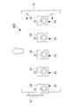
- the desulfurization apparatus 100 of the present embodiment includes an absorption tower 10, a spray pipe 20, a demister 30, and a circulation pump 40.
- the absorption tower 10 is a cylindrical casing which is formed to extend in the vertical direction and serves as a passage for exhaust gas.
- the absorption tower 10 guides the exhaust gas containing the sulfur oxide introduced from the exhaust gas introducing portion 11 formed on the side surface upward in the vertical direction.
- the absorption tower 10 discharges the exhaust gas from which sulfur oxides have been removed from the exhaust gas discharge portion 12 formed above in the vertical direction.
- the spray pipe 20 is a cylindrical member disposed along the horizontal direction inside the absorption tower 10. As shown in FIG. 1, the spray pipe 20 discharges the absorbing liquid upward in the vertical direction to bring the exhaust gas introduced from the exhaust gas introducing unit 11 into gas-liquid contact with the absorbing liquid.
- the absorbing liquid is a liquid containing lime, and the limestone method removes sulfur oxides contained in the exhaust gas.
- the absorbing liquid discharged from the spray pipe 20 upward in the vertical direction falls and accumulates at the bottom 13 of the absorption tower 10.
- the absorption liquid accumulated in the bottom 13 is supplied to the spray pipe 20 by the circulation pump 40.
- the demister 30 is, for example, a folded plate type demister, and removes the mist of the absorbing liquid generated inside the absorption tower 10 by physical collision.
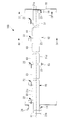
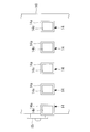
- FIG. 2 is a side view of the spray pipe 20 of the desulfurization apparatus 100 shown in FIG.
- a plurality of spray pipes 20 are inserted from the outside of the absorber 10 into the inside of the absorber 10.
- five spray pipes 20 arranged at predetermined positions in the vertical direction are arranged at equal intervals in the horizontal direction.
- the number of spray pipes 20 included in the desulfurization apparatus 100 may be any number other than five depending on the size of the absorption tower 10 or the like. Further, the spray pipes 20 may be disposed in a plurality of stages at different positions in the vertical direction.
- the spray pipe 20 is provided with a mounting flange (first flange portion) 24 and a supply port 25.
- the mounting flange 24 is a member for attaching the spray pipe 20 to the opening 14 (see FIG. 4) provided in the absorption tower 10.
- the mounting flange 24 is mounted to a mounting flange (second flange portion) (see FIGS. 12 and 17) disposed around the opening hole 14e of the opening 14 of the absorption tower 10 by a plurality of fasteners (not shown). .
- a manhole 15 is provided for a worker to pass through. The manhole 15 can be used also when bringing in parts for maintenance from the outside of the absorption tower 10 to the inside or when carrying out used parts from the inside of the absorption tower 10 to the outside.
- FIG. 3 is a plan view of the five spray pipes 20 shown in FIG. 2 as viewed from above.
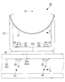
- FIG. 4 is a view on arrow II of the spray pipe 20 of the desulfurization apparatus 100 shown in FIG.
- the spray pipe 20 has a pipe portion 21, a plurality of nozzle portions 22 (nozzle holders 22 b), and a plurality of leg portions 23.
- the pipe portion 21 is a cylindrical member extending linearly from the proximal end 21b to the distal end 21a along the horizontal axis X1 and having the distal end 21a closed.
- the proximal end 21b of the pipe portion 21 is provided with a supply port 25 to which the absorbent is supplied from the circulation pump 40, and an absorbent liquid supply pipe 41 (see FIG. 1) is connected around the supply port 25.
- a flange 26 is formed for this purpose.
- the absorbent supplied from the supply port 25 to the inside of the pipe 21 is guided to the plurality of nozzles 22.
- the length from the proximal end 21b to the distal end 21a along the axis X1 of the pipe portion 21 is 3 m or more and 15 m or less.
- the outer diameter of the pipe part 21 is 200 mm or more and 400 mm or less.
- the plurality of nozzle portions 22 are members disposed at equal intervals along the axis X1 at a plurality of locations on the upper end portion (upper portion) 21c in the vertical direction of the pipe portion 21.
- FIG. 5 is a partially enlarged view of the nozzle portion 22 shown in FIG. As shown in FIG. 5, the nozzle portion 22 has a spray nozzle 22a, a nozzle holder 22b, and a gasket 22c.
- the spray nozzle 22a is a member for guiding the absorbent flowing in the horizontal direction along the axis X1 along the axis X1 along the axis X2 in the vertical direction.
- the spray nozzle 22 a discharges the absorption liquid supplied from the circulation pump 40 upward in the vertical direction, and brings the exhaust gas and the absorption liquid into gas-liquid contact inside the absorption tower 10.
- the spray nozzle 22a is detachably attached to the nozzle holder 22b, and is formed of, for example, SiC (silicon carbide).
- the nozzle holder 22 b is a member which is disposed at a plurality of locations on the upper end portion 21 c of the pipe portion 21 and which is formed in a cylindrical shape along the axis X 2 in the vertical direction.
- the nozzle holder 22 b guides the absorbing liquid flowing in the pipe portion 21 in the horizontal direction to the upper side in the vertical direction.
- the lower end side of the spray nozzle 22a is inserted into the nozzle holder 22b.
- a flange is formed at the upper end of the nozzle holder 22b.
- a flange having the same shape as that of the nozzle holder 22b is formed on the spray nozzle 22a.
- the flange of the spray nozzle 22a and the flange of the nozzle holder 22b are fastened by a plurality of fasteners (not shown) while sandwiching an annular gasket 22c (for example, made of butyl rubber) There is.
- the plurality of leg portions 23 are members attached to the lower end portion (lower portion) 21 d of the pipe portion 21.
- the legs 23 are attached to a plurality of places including the tip 21 a of the pipe 21.
- the plurality of leg portions 23 transmit the load of the pipe portion 21 to the pipe support (support portion) 91, the support beam (support portion) 92, and the support beam (support portion) 93 installed in the absorption tower 10.
- the pipe support 91, the support beam 92, and the support beam 93 are members installed in the absorption tower 10 to support the spray pipe 20.
- the reaction force when discharging the absorbing liquid applied to the pipe portion 21 and the impact force caused by the falling and contacting of the absorbing liquid are transmitted to the absorption tower 10 through the plurality of leg portions 23.
- the position of the lower end in the vertical direction of the leg portion 23 corresponds to the opening hole 14 e of the opening portion 14 in a state where the leg portion 23 is supported by the pipe support 91 and the support beams 92 and 93. It is installed in the absorption tower 10 so as to be lower than the lower end in the vertical direction (see FIG. 12).
- FIG. 6 is a II-II arrow view of the spray pipe 20 portion of the desulfurization apparatus 100 shown in FIG.
- FIG. 7 is a III-III arrow view of the spray pipe 20 portion of the desulfurization apparatus 100 shown in FIG.
- the leg 23 shown in FIG. 6 and FIG. 7 is attached to the lower end 21 d of the tip 21 a of the pipe 21.
- the upper end of the leg portion 23 is attached to the pipe portion 21.
- the leg part 23 has the installation surface (1st surface) 23a in the lower end.
- the installation surface 23a is a flat installation surface along a horizontal surface, it may be another aspect.
- the installation surface 23a may have a polygonal or arc shape in cross section orthogonal to the axis X1.
- a pipe support 91 formed of a metal material or the like is installed on the inner wall surface of the absorption tower 10.
- the pipe support 91 has a support surface (second surface) 91 a for supporting the spray pipe 20 at its upper end.
- the support surface 91a is a flat installation surface along a horizontal surface, but may be in another aspect.
- the support surface 91a may have a polygonal or arc shape in cross section orthogonal to the axis X1.
- the upper surface of the support surface 91a may be coated with a resin lining to protect the support surface 91a from corrosion and the like.
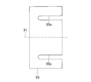
- a shim plate (plate member) 99 is disposed between the mounting surface 23a at the lower end of the leg portion 23 and the support surface 91a at the upper end of the pipe support 91.
- the leg portion 23 is disposed in a state where the installation surface 23 a is opposed to the support surface 91 a. That is, the spray pipe 20 is supported by the pipe support 91 in a state where the installation surface 23 a is opposed to the support surface 91 a. Therefore, the rotation direction angle around the axial center of the pipe portion 21 is determined based on the support surface 91a.
- the axis of the spray nozzle 22a attached to the pipe portion 21 has a rotational direction angle along the vertical direction
- the time and effort of adjusting the rotational direction angle of the pipe portion 21 becomes unnecessary.
- the pipe portion 21 is supported by the pipe support 91 by the “face” via the leg portion attached to the pipe portion 21, for example, when the pipe portion is directly supported by the pipe support without providing the leg portion Compared to the above, the local stress applied to the portion of the pipe portion 21 in contact with the pipe support 91 can be reduced, and further, the pipe portion 21 is subjected to the reaction force accompanying the discharge of the absorbing liquid and the impact force due to the falling absorbing liquid. It is possible to reduce the possibility that the rotational direction angle of the above is deviated and the discharge direction of the absorbing liquid does not follow the vertical direction.
- the shim plate 99 is a member for adjusting the position of the installation surface 23 a in the vertical direction with respect to the support surface 91 a in order to install the pipe portion 21 in the horizontal direction. 6 and 7, the shim plate 99 is disposed between the installation surface 23a and the support surface 91a, but if it is not necessary to install the pipe portion 21 in the horizontal direction, the shim plate 99 is used. It does not have to be arranged. In that case, the installation surface 23a and the support surface 91a are disposed in direct contact with each other. Further, the shim plate 99 can be used with the appropriate thickness in the vertical direction in order to install the pipe portion 21 in the horizontal direction. In addition, a plurality of shim plates 99 may be stacked and disposed.
- the fastening portion 70 includes a fastening bolt 71 having a head and a shaft, a washer 72 disposed between the head of the fastening bolt 71 and the pipe support 91, and a fastening that is fastened to the shaft of the fastening bolt 71. It has nuts 73 and 74 and a washer 75 disposed between the fastening nut 74 and the leg 23.
- a clearance is provided below the fastening nut 74, and the fastening nut 73 is tightened in that state, or after the fastening nut 74 is tightened, the fastening nut 73 is tightened and the fastening nut 74 is loosened.
- the fastening nut 73 and the fastening nut 74 can be in a fastening state in which they do not move in the vertical direction. In this case, even when the pipe portion 21 is deformed by thermal expansion, it is possible to suppress a defect that the deformation or breakage occurs in the fastening portion.
- FIG. 8 is a view on arrow IV-IV of the spray pipe 20 of the desulfurization apparatus 100 shown in FIG.
- FIG. 9 is a VV arrow view of the spray pipe 20 portion of the desulfurization apparatus 100 shown in FIG.
- the leg portion 23 shown in FIGS. 8 and 9 is attached to an intermediate portion between the distal end portion 21 a and the proximal end portion 21 b of the pipe portion 21.
- the upper end of the leg portion 23 is attached to the pipe portion 21.
- the leg part 23 has the installation surface (1st surface) 23a in the lower end.
- the installation surface 23a is a flat installation surface along a horizontal surface, it may be another aspect.
- the installation surface 23a may have a polygonal or arc shape in cross section orthogonal to the axis X1.
- a support beam 92 and a support beam 93 which are formed of a metal material or the like and extend in the horizontal direction are installed.
- the support beam 92 has a support surface (second surface) 92a at its upper end.
- the support beam 93 has a support surface (second surface) 93a at its upper end.
- the support surfaces 92a and 93a are flat installation surfaces along the horizontal surface, but may be other embodiments.
- the support surfaces 92a and 93a may have a polygonal or arc shape in cross section orthogonal to the axis X1.
- the upper surfaces of the support surfaces 92a, 93a may be coated with a resin lining to protect the support surfaces 92a, 93a from corrosion and the like.
- a shim plate 99 is disposed between the mounting surface 23 a at the lower end of the leg 23 and the support surfaces 92 a and 93 a at the upper end of the support beams 92 and 93.
- the leg portion 23 is disposed in a state in which the mounting surface 23a is opposed to the support surfaces 92a and 93a.
- the spray pipe 20 is supported by the support beams 92, 93 in a state where the installation surface 23a is opposed to the support surfaces 92a, 93a.
- the rotation direction angle around the axial center of the pipe portion 21 is determined based on the support surfaces 92a and 93a.
- the axial center of the spray nozzle 22a attached to the pipe portion 21 (nozzle holder 22b) has a rotational direction angle along the vertical direction
- the pipe portion 21 is supported by the support beams 92 and 93 in a “face” manner via the leg portions attached to the pipe portion 21, for example, the support beam 92 directly without providing the leg portion in the pipe portion Compared with the case of supporting by 93, the local stress applied to the portion of the pipe portion 21 in contact with the support beams 92, 93 can be reduced, and further, the reaction force accompanying the discharge of the absorbing liquid and the impact force due to the falling of the absorbing liquid As a result, it is possible to reduce the possibility that the rotational direction angle of the pipe portion 21 is deviated and the discharge direction of the absorbing liquid is not along the vertical direction.
- the shim plate 99 is a member that adjusts the vertical position of the installation surface 23a with respect to the support surfaces 92a and 93a in order to install the pipe portion 21 in the horizontal direction.
- the shim plate 99 is disposed between the installation surface 23a and the support surfaces 92a and 93a, but if it is not necessary to install the pipe portion 21 along the horizontal direction, the shim plate It is not necessary to place 99.
- the installation surface 23a and the support surfaces 92a and 93a are disposed in direct contact with each other.
- the shim plate 99 can be used with the appropriate thickness in the vertical direction in order to install the pipe portion 21 in the horizontal direction.
- a plurality of shim plates 99 may be stacked and disposed.
- the leg portion 23, the support beams 92 and 93, and the shim plate 99 are fastened by a fastening portion (second fastening portion) 80.
- the fastening portion 80 is fastened to a fastening bolt 81 having a head and a shaft, a washer 82 disposed between the head of the fastening bolt 81 and the support beams 92 and 93, and a shaft of the fastening bolt 81 And a washer 85 disposed between the fastening nut 84 and the leg 23.
- the reason why the two fastening nuts 83 and 84 are fastened to the shaft portion of the fastening bolt 81 is to make it possible to provide a gap below the fastening nut 84.
- the spray pipe 20 is formed by integrally forming the pipe portion 21, the nozzle holder 22b of the nozzle portion 22, and the leg portion 23 with fiber-reinforced plastic.
- the spray nozzle 22a attached to the nozzle holder 22b is made of, for example, SiC (silicon carbide).
- the spray pipe 20 of the present embodiment is manufactured by integrally forming the pipe portion 21, the nozzle holder 22b of the nozzle portion 22, and the leg portion 23 of fiber reinforced plastic.
- the spray pipe 20 is highly likely to be abraded due to the absorption liquid discharged upward falling and colliding.
- the fiber reinforced plastic since the fiber reinforced plastic is used for the spray pipe 20, the wear resistance is high. Furthermore, the resistance to corrosion is also high.
- a metal material for example, UNS S31254 or Hastelloy C-276 may be used instead of the fiber reinforced plastic.
- 316 L or the like may be used.
- the leg portion 23 may be separately manufactured of a metal material and attached to the spray pipe 20 by welding or screw connection.
- the leg portion 23 is a rigid body.
- FIG. 10 is a cross-sectional view of the leg 23 shown in FIG. 9 taken along the line VI-VI.
- the installation surface 23a of the leg portion 23 is formed with an insertion hole 23b into which the fastening bolt 81 is inserted.
- the insertion hole 23b has a length L2 in the direction along the axis X1 longer than the length L1 in the direction orthogonal to the axis X1.
- the reason why the insertion hole 23b is a long hole is that the insertion hole 23b contacts the fastening bolt 81 when the spray pipe 20 is thermally expanded and the leg 23 moves toward the tip 21a of the pipe 21. It is for suppressing.
- the insertion holes 23b provided in the installation surface 23a of the legs 23 are elongated holes, and the insertion holes (not shown) provided in the pipe support 91 and the support beams 92 and 93 are circular holes.
- the insertion hole 23b provided in the installation surface 23a of the leg portion 23 is a circular round hole, and the insertion hole provided in the pipe support 91 and the support beams 92, 93 has an axial line rather than the length L1 in the direction orthogonal to the axial line X1.
- the length L2 in the direction along X1 may be a long hole.
- both the insertion holes 23b provided in the installation surface 23a of the legs 23 and the insertion holes provided in the pipe support 91 and the support beams 92 and 93 may be long holes.
- FIG. 11 is a VI-VI arrow view of the plate-like member shown in FIG.
- the shim plate 99 is formed with a notch 99a opening toward one end.
- the cutaway portion 99a is a portion which allows the fastening bolt 81 to be inserted in a state of being disposed between the installation surface 23a of the leg portion 23 and the support surfaces 92a and 93a of the support beams 92 and 93.
- the notch 99a is a portion that enables the fastening bolt 71 to be inserted in a state (see FIG. 7) disposed between the installation surface 23a of the leg 23 and the support surface 91a of the pipe support 91.
- the shim plate 99 Since the shim plate 99 has the notch 99 a, it can be inserted between the mounting surface 23 a of the leg 23 and the support surface 91 a of the pipe support 91 without removing the fastening bolt 71. Similarly, since the shim plate 99 has the notch 99a, the shim plate 99 can be inserted between the mounting surface 23a of the leg 23 and the support surfaces 92a, 93a of the support beams 92, 93 without removing the fastening bolt 81. it can. As described above, when installing the leg portion 23 of the spray pipe 20 to the pipe support 91 and the support beams 92 and 93, the spray pipe 20 is disposed in the horizontal direction by installing the shim plate 99 at an appropriate position. Can be adjusted to
- the shim plate 99 is disposed in a state in which the notch 99a is open toward the tip 21a of the pipe portion 21 along the axis X1. That is, the notch 99 a of the shim plate 99 is not open at the proximal end 21 b side of the pipe portion 21. Therefore, the shim plate 99 does not move toward the tip 21a because the shim plate 99 contacts the fastening bolts 71 and 81 even if a force directed to the tip 21a is applied from the leg 23. Therefore, the problem that the shim plate 99 moves toward the tip end portion 21a and falls off the pipe support 91 and the support beams 92 and 93 can be prevented.
- a clearance CL is formed between the tip 21 a of the pipe portion 21 and the inner wall surface of the absorber 10.
- the clearance CL is a distance necessary for the tip 21 a of the pipe portion 21 not to contact the inner wall surface of the absorption tower 10.
- the spray pipe 20 is thermally expanded by the high temperature exhaust gas. Therefore, the pipe portion 21 of the present embodiment is disposed such that the clearance CL can be secured even in the state where the spray pipe 20 is heated by the exhaust gas.
- the pipe portion 21 is installed so that the clearance CL can be secured even if the thermal expansion occurs.
- the clearance CL between the tip 21 a of the pipe portion 21 and the inner wall surface of the absorption tower 10 is 10 mm or more and 100 mm or less in a state where the exhaust gas is not heated.
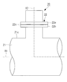
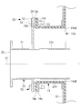
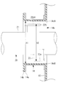
- FIG. 12 is a partially enlarged view of the mounting flange 24 portion of the spray pipe 20 of the desulfurization apparatus 100 shown in FIG.
- the opening 14 of the absorption tower 10 is formed in a tubular shape so as to open toward the side of the absorption tower 10 and to extend along the axis X1.
- the opening 14 has an opening 14 e that opens to the side.
- a flange (second flange portion) 14 a disposed around the opening hole 14 e is formed.
- a resin-made lining portion 14b is provided on the inner peripheral surface of the flange 14a to protect the flange 14a from corrosion or the like due to exhaust gas.
- the mounting flange 24 of the spray pipe 20 has a mounting surface (first mounting surface) 24 a that protrudes from the outer peripheral surface of the pipe portion 21 and extends in the vertical direction.
- first mounting surface first mounting surface
- second mounting surface second mounting surface
- the mounting surface 24a and the mounting surface 14d are mounted in a state of facing each other across the gasket 14c.
- the mounting flange 24 of the spray pipe 20 is attached to the flange 14 a of the opening 14 by a fastening portion (first fastening portion) 50 with the gasket 14 c (for example, made of butyl rubber) interposed therebetween.
- the first fastening portion 50 includes a fastening bolt 51 having a head and a shaft, a washer 52 disposed between the head of the fastening bolt 51 and the mounting flange 24, and a fastening bolt And a fastening nut 53 fastened to the shaft portion 51.
- the first fastening portions 50 are shown only at the two upper and lower places in the vertical direction, but the first fastening portions 50 are provided at a plurality of places so as to surround the outer peripheral end of the mounting flange 24. .
- the mounting flange 24 of the spray pipe 20 and the flange 14 a of the opening 14 are detachably mounted by a fastener including a fastening bolt 51 and a fastening nut 53. Therefore, when replacing or inspecting the spray pipe 20, the spray pipe 20 can be easily removed from the absorption tower 10 by releasing the fastening between the fastening bolt 51 and the fastening nut 53.
- the desulfurization apparatus 100 of this embodiment is provided with five spray pipes 20 as shown in FIG. Moreover, the absorption tower 10 with which the desulfurization apparatus 100 of this embodiment is equipped has five flanges 14a disposed around the opening hole 14e formed at five places equal to the number of the spray pipes 20 and five flanges 14a. Equipped with And five attachment flanges 24 of five spray pipes 20 are attached to each of five flange 14a by one to one.
- the desulfurization apparatus 100 according to the present embodiment includes five spray pipes 20, the number may be an arbitrary number. In this case, the absorption tower 10 is provided with the same number of opening holes 14 e as the spray pipes 20 and the flanges 14 a disposed around the opening holes 14 e.
- the spray pipe 20 attached to the opening 14 via the mounting flange 24 is inclined from the horizontal direction. Therefore, the thickness of the portion of the lining portion 14b to be held by the mounting flange 24 is appropriately adjusted so that the end face of the opening portion 14 coincides with the vertical direction.
- a sealing material may be applied between the mounting flange 24 and the gasket 14 c so that the end face of the opening 14 coincides with the vertical direction. The application of the sealing material may be performed instead of adjusting the thickness of the lining portion 14b, or may be performed in addition to adjusting the thickness of the lining portion 14b.
- the mounting surface 14d of the opening 14 and the mounting surface 24a formed on the mounting flange 24 of the spray pipe 20 are opposed to each other with the gasket 14c interposed therebetween. It is attached to the opening 14 of the absorber 10.
- the lower end 14eB of the opening 14e is lower than the lower end 21d of the pipe 21 in the vertical direction, and the upper end 14eA of the opening 14e is higher than the upper end 21c of the pipe 21.
- the pipe portion 21 is disposed in such a state that the lower end portion 21d does not contact the inner peripheral surface of the opening portion 14 and the opening hole 14e.
- the spray pipe 20 is attached to the opening portion 14 so that the position in the vertical direction of the axis X1 along which the pipe portion 21 extends is lower than the vertical center position of the opening hole 14e. ing.
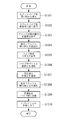
- FIG. 13 is a flowchart showing an installation method of installing the spray pipe 20 inside the absorption tower 10.
- Each process shown in FIG. 13 is a process executed by a worker or work equipment such as a crane operated by the worker.
- step S1301 the operator lifts the spray pipe 20 placed outside the absorption tower 10 by a crane (not shown) and inserts the spray pipe 20 into the opening 14 of the absorption tower 10 in the horizontal direction. Do. The worker adjusts the position of the pipe portion 21 with a guide rope (not shown) connected to the pipe portion 21 so that the spray pipe 20 does not contact the absorption tower 10. As shown in FIG. 14, the spray pipe 20 is inserted into the opening 14 of the absorption tower 10 in a state where the spray nozzle 22a is not attached to the nozzle holder 22b.
- the height H1 in the vertical direction from the lower end 14eB to the upper end 14eA of the opening hole 14e is from the installation surface 23a of the leg 23 to the nozzle holder 22b. It is higher than the height H2 in the vertical direction up to the upper end 22bA. This is done to allow the spray pipe 20 to be inserted into the interior of the absorber 10 through the opening 14 without the spray nozzle 22a attached to the nozzle holder 22b.
- step S1302 the worker arranges the spray pipe 20 inserted into the inside of the absorption tower 10 from the opening 14 inside the absorption tower 10 so as to be supported by the plurality of legs 23. As shown in FIG. 2, the worker sprays so that the installation surfaces 23 a of the plurality of legs 23 face the support surface 91 a of the pipe support 91 and the support surfaces 92 a and 93 a of the support beams 92 and 93. Arrange the pipe 20.
- step S1303 the operator corrects the verticality of the mounting surface 14d such that the mounting surface 24a of the mounting flange 24 is disposed along the vertical direction.
- the correction of the vertical degree of the mounting surface 14d is performed, for example, by adjusting the thickness of the lining portion 14b.
- the thickness of the sealant for example, made of silicone
- the mounting surface 24a of the mounting flange 24 is disposed along the vertical direction.
- step S1304 temporary tightening process
- the operator temporarily tightens the mounting flange 24 of the spray pipe 20 and the flange 14a of the opening 14 of the absorption tower 10 using the first fastening portion 50.
- the plurality of first fastening portions 50 are provisionally It is connected by tightening.
- step S1305 the operator temporarily tightens the mounting flange 24 and the flange 14a of the opening 14 so that the axis X1 of the pipe portion 21 coincides with the horizontal direction. Adjust the degree.
- the term “horizontal direction” as used herein includes an angle within the range of desired tolerance from the horizontal direction (the same applies hereinafter).
- the worker inserts the thickness of the shim plate 99 inserted between the pipe support 91 and the leg 23, the thickness of the shim plate 99 inserted between the support beam 92 and the leg 23, the support beam
- the thickness of the shim plate 99 to be inserted between 93 and the leg 23 is appropriately selected, and the height of the mounting surface 23a with respect to the support surfaces 91a, 92a, 93a is adjusted.
- the operator arranges a horizontal scale (not shown) on the upper surface of the nozzle holder 22b of the spray pipe 20 and visually checks the horizontal scale to check whether the axis X1 of the pipe portion 21 coincides with the horizontal direction Do. When the operator confirms that the levelness indicated by the leveler is within the desired tolerance, the operator ends the adjustment of the levelness.
- step S1305 adjusts the levelness of the pipe portion 21 in step S1305 (adjustment step), and then, the leg disposed adjacent to the pipe support 91 and the tip 21a of the spray pipe 20 in step S1306 (connection step)
- the part 23 is connected by the fastening part 70.
- the operator inserts the shaft portion of the fastening bolt 71 from the lower side of the pipe support 91, and fastens the fastening nuts 73 and 74 to the shaft portion which penetrates the leg portion 23, thereby the pipe support 91 and the leg portion Connect 23
- the pipe support 91 and the leg 23 may be temporarily tightened in the connecting step of step S1306 so that the distance between the mounting flange 24 and the opening 14 can be finely adjusted in step S1308 (final tightening step) to be performed later.
- step S1306 even when the pipe portion 21 is thermally expanded, the pipe support 91 and the leg portion 23 are connected in a state in which the leg portion 23 attached to the pipe portion 21 can move along the axis X1. Be done.
- step S1307 connection step
- the worker connects the support beams 92 and 93 and the leg portion 23 by the fastening portion 80. Specifically, the worker inserts the shaft portion of the fastening bolt 81 from the lower side of the support beams 92 and 93, and fastens the fastening nuts 83 and 84 to the shaft portion penetrating the leg portion 23, thereby supporting the support beam 92, 93 and the leg 23 are connected.
- the support beams 92 and 93 and the leg portion 23 are temporarily tightened so that the distance between the mounting flange 24 and the opening 14 can be finely adjusted in step S1308 (final tightening step) to be performed later. Good.
- step S1307 even when the pipe portion 21 is thermally expanded, the support beams 92 and 93 and the leg portion 23 can be moved with the leg portion 23 attached to the pipe portion 21 movable along the axis X1. Are linked.
- connection between the support beam 92 and the leg 23 is performed prior to the connection between the support beam 93 and the leg 23.
- the connection process of step S1307 is performed in order from the distal end portion 21a of the pipe portion 21 to the proximal end portion 21b.
- step S1308 the final tightening step
- the operator checks the gap between the mounting flange 24 of the spray pipe 20 and the opening 14 of the absorption tower 10, and confirms that there is no excessive gap. If a gap is present, the position of the spray pipe 20 is finely adjusted to eliminate the gap. Thereafter, the mounting flange 24 and the flange 14 a of the opening 14 are fully tightened using the first fastening portion 50.
- the mounting flange 24 of the spray pipe 20 and the flange 14a of the opening 14 face each other with the mounting surface 24a of the mounting flange 24 and the mounting surface 14d of the flange 14a sandwiching the gasket 14c.
- the plurality of first fastening portions 50 are connected by being fully tightened.
- full tightening refers to increasing the torque (Nm) and tightening the first fastening portion 50 temporarily tightened in step S1304.
- steps S1301 to S1308 the method for installing one spray pipe 20 has been described. However, by repeating steps S1301 to S1308, a plurality of spray pipes 20 are installed.
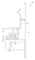
- step S1309 installation step
- the worker carries in a plurality of scaffolding boards (scaffolding members) 60 from the outside of the absorption tower 10 via the manhole 15 into the interior of the absorption tower 10, and as shown in FIG. It is installed at the upper end 21 c of the pipe portion 21 of the pipe 20.
- the scaffolding plate 60 is placed around each of the plurality of spray pipes 20.
- the scaffolding plate 60 is a member on which a worker rests and works to attach the spray nozzle 22a to the nozzle holder 22b of the pipe portion 21.
- step S1310 the worker mounts the spray nozzle 22a on the nozzle holder 22b in a state of being placed on the scaffolding plate 60.
- the operator attaches the spray nozzle 22a to the nozzle holder 22b while moving on the scaffold plate 60 with respect to the plurality of nozzle holders 22b provided in the plurality of spray pipes 20.
- step S1306 connection process
- step S1307 connection process
- the worker After attaching the spray nozzles 22a to all the nozzle holders 22b, and after the final tightening is completed, the worker takes a plurality of scaffolding plates 60 through the manholes 15 as the absorber 10. Take out of the Then, the worker moves from the manhole 15 to the outside of the absorber 10 and ends the process according to the present flow.
- the mounting flange 24 of the spray pipe 20 disposed inside the absorption tower 10 and the flange 14 a disposed around the opening hole 14 e of the absorption tower 10 are removable. Is attached to The spray pipe 20 can be easily removed from the absorption tower 10 for replacement or inspection, so that it is easy to replace or inspect the spray pipe 20 if a failure such as damage or clogging occurs in part of the spray pipe 20. It is possible to do
- the mounting surface 24a of the mounting flange 24 of the spray pipe 20 is made to face the mounting surface 14d of the flange 14a of the opening 14 of the absorption tower 10, and mounting along the vertical direction
- the spray pipe 20 can be attached to the opening 14 of the absorber 10 using the surface 14 d as a reference surface. Therefore, it is possible to reduce the number of steps for adjusting the axial direction of the pipe portion 21 of the splay pipe 20 in the horizontal direction so that the rotation direction angle about the axial center becomes a predetermined angle. The work when inserting from the outside of the tower 10 and installing inside becomes easy.
- the mounting flange 24 of the spray pipe 20 is fastened to the flange 14 a of the opening 14 of the absorption tower 10, and the spray pipe 20 is attached to the absorption tower 10. It is possible to prevent the absorption liquid and the exhaust gas from leaking out through the opening 14 (opening hole 14 e) of the tower 10.
- the desulfurization apparatus 100 of the present embodiment includes a predetermined number (five) of spray pipes 20, and the absorption tower 10 has a predetermined number (five places) of opening holes 14e and a predetermined number (five) of flanges 14a. And a predetermined number (five) of mounting flanges 24 are attached to each of a predetermined number (five) of the flanges 14 a in a one-to-one manner. By doing this, it is possible to remove from the absorption tower 10 only the spray pipes 20 that need to be replaced or inspected among the predetermined number of spray pipes 20.
- the position in the vertical direction of the axis X1 in which the pipe portion 21 extends is disposed lower than the central position in the vertical direction of the opening hole 14e.
- a sufficient space is secured above the pipe portion 21, so the installation work of the pipe portion 21 can be easily performed.
- the installation work can be performed while moving the pipe part 21 downward along the gravity after inserting the pipe part 21 into the opening hole 14e, the installation work of the pipe part 21 is facilitated and the installation accuracy is also improved.
- the pipe part 21 is arrange
- the spray pipe 20 includes the leg portion 23 attached to the lower portion in the vertical direction of the pipe portion 21 and having the installation surface 23a, and the position of the lower end in the vertical direction of the leg portion 23 is , And the lower end of the opening hole 14e in the vertical direction.
- the installation work can be performed while moving the leg portion 23 pulled up above the opening hole 14 e downward along the gravity when passing the opening hole 14 e of the absorption tower 10. Therefore, the installation work at the time of installing the leg portion 23 of the spray pipe 20 on the pipe support 91 and the support beams 92 and 93 provided in the absorption tower 10 can be easily and accurately performed.
- the lower end 14eB of the opening 14e is lower than the lower end 21d of the pipe 21 in the vertical direction, and the upper end of the opening 14e is lower than the upper end 21c of the pipe 21.
- the part 14eA is disposed high. Therefore, after the pipe portion 21 is inserted from the outside of the absorption tower 10 to the inside along the horizontal direction from the opening hole 14e of the opening portion 14, the pipe portion 21 is positioned vertically at the upper end 14eA and the lower end 14eB of the opening 14e. It is installed in the inside of the absorber 10 in the state maintained between.
- the amount of movement of the spray pipe 20 in the vertical direction from the insertion into the interior of the absorption tower 10 to the installation thereof is small. Therefore, when the spray pipe 20 is inserted from the outside of the absorber 10 and installed inside, the levelness of the spray pipe 20 can be accurately maintained.
- a gap is secured between the upper end 21c of the pipe portion 21 and the upper end 14eA of the opening hole 14e, and a gap is secured between the lower end 21d of the pipe portion 21 and the lower end 14eB of the opening hole 14e. . Therefore, when the spray pipe 20 is inserted from the outside of the absorption tower 10, it is possible to allow the pipe portion 21 to move in the vertical direction to some extent.
- the height of the perpendicular direction of the spray pipe 20 Is the height H2 from the mounting surface 23a of the leg 23 to the upper end 22bA of the nozzle holder 22b.
- the height H1 from the lower end portion 14eB of the opening hole 14e to the upper end portion 14eA is higher than the height H2 of the spray pipe 20 in the vertical direction. Therefore, the spray pipe 20 having the legs 23 can be inserted from the outside to the inside of the absorber 10 through the opening hole 14e.
- the spray nozzle 22a is attached to each of the plurality of nozzle holders 22b, so that the absorbing liquid can be discharged from the spray pipe 20.
- the opening 14 formed on the side surface of the absorption tower 10 is configured by a rectangular opening 14 e and a rectangular flange 14 a around the opening 14 e.
- the opening hole 14e is rectangular, the position of the spray pipe 20 can be changed and adjusted in a wide range in both the vertical direction and the horizontal direction, and the installation of the spray pipe 20 becomes easy.
- the shapes of the mounting flange 24 and the flange 14a may be rectangular.
- the rectangle includes not only a shape in which four corners are orthogonal but also a partially rounded shape.
- the flanges 14a and the mounting flanges 24 are the upper left and right two places in the vertical direction and the lower left and right in the vertical direction. Although it was a rectangular shape which has a corner in each of two places, another aspect may be sufficient.
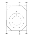
- the flange 14a and the mounting flange 24 may be shaped as shown in FIG.
- FIG. 15 is a view of the desulfurization apparatus from the side of the absorption tower 10.
- the flange 14a and the mounting flange 24A are horizontal with the horizontal line passing through the upper end and the lower end in the vertical direction.
- the four corner portions CP1, CP2, CP3, and CP4 where the left end and the right end of the direction intersect with each other may be cut away.
- the flange 14a is not shown in figure, suppose that it is the same shape as the attachment flange 24A.
- the work space of the worker is sufficiently secured.
- the worker cuts off the corner parts.
- the installation work of the spray pipe 20 is facilitated, for example, since it is possible to work by putting a hand on the back side of the flange from an essential part.
- the flange 14a and the mounting flange 24A may have other shapes as long as the corner portions CP1, CP2, CP3, and CP4 are notched. For example, instead of the octagonal shape shown in FIG. 15, each corner may be rounded. Also, the flange 14a and the mounting flange 24A may be formed in an elliptical shape.
- the center position of the left end and the right end of the mounting flange 24 and the center position of the pipe portion 21 are horizontal.
- the center position C1 of the left end l and the right end r of the mounting flange 24B and the center position C2 of the pipe portion 21 are horizontal. It may be separated.
- the center position C1 of the left end l and the right end r of the mounting flange 24B and the center position C3 of the pipe portion 21 are horizontal. It may be spaced apart in the direction.
- the desulfurization apparatus 100 is an apparatus using a lime gypsum method in which an absorbing liquid containing lime is brought into gas-liquid contact with exhaust gas to remove sulfur oxides contained in the exhaust gas. May be For example, it may be a desulfurization apparatus using a seawater desulfurization method that uses seawater containing an alkaline component as an absorbent.
- the spray pipe 20 is disposed along the horizontal direction inside the absorption tower 10, but the spray pipe 20 may be disposed inclined at an angle from the horizontal direction. .
- the mounting flange 24 of the spray pipe 20 is attached to the flange 14 a of the opening 14 of the absorption tower 10, but another embodiment may be employed.
- the mounting flange 24 may be directly attached to the side wall of the absorption tower 10 using a fastener.
- the portion surrounding the opening in the side wall of the absorption tower 10 is a flange portion to which the mounting flange 24 of the spray pipe 20 is attached.
Landscapes
- Chemical & Material Sciences (AREA)
- Engineering & Computer Science (AREA)
- Chemical Kinetics & Catalysis (AREA)
- Environmental & Geological Engineering (AREA)
- Analytical Chemistry (AREA)
- General Chemical & Material Sciences (AREA)
- Oil, Petroleum & Natural Gas (AREA)
- Health & Medical Sciences (AREA)
- Biomedical Technology (AREA)
- Treating Waste Gases (AREA)
- Gas Separation By Absorption (AREA)
- Nozzles (AREA)
Priority Applications (4)
| Application Number | Priority Date | Filing Date | Title |
|---|---|---|---|
| US16/603,931 US11364467B2 (en) | 2017-09-20 | 2018-09-18 | Desulfurization device |
| CN201880025253.0A CN110536738B (zh) | 2017-09-20 | 2018-09-18 | 脱硫装置 |
| EP18859520.1A EP3685906A4 (en) | 2017-09-20 | 2018-09-18 | DESULFURIZING DEVICE |
| KR1020197030209A KR102310398B1 (ko) | 2017-09-20 | 2018-09-18 | 탈황 장치 |
Applications Claiming Priority (2)
| Application Number | Priority Date | Filing Date | Title |
|---|---|---|---|
| JP2017180339A JP6679548B2 (ja) | 2017-09-20 | 2017-09-20 | 脱硫装置 |
| JP2017-180339 | 2017-09-20 |
Publications (1)
| Publication Number | Publication Date |
|---|---|
| WO2019059181A1 true WO2019059181A1 (ja) | 2019-03-28 |
Family
ID=65809795
Family Applications (1)
| Application Number | Title | Priority Date | Filing Date |
|---|---|---|---|
| PCT/JP2018/034496 Ceased WO2019059181A1 (ja) | 2017-09-20 | 2018-09-18 | 脱硫装置 |
Country Status (6)
| Country | Link |
|---|---|
| US (1) | US11364467B2 (enExample) |
| EP (1) | EP3685906A4 (enExample) |
| JP (1) | JP6679548B2 (enExample) |
| KR (1) | KR102310398B1 (enExample) |
| CN (1) | CN110536738B (enExample) |
| WO (1) | WO2019059181A1 (enExample) |
Families Citing this family (4)
| Publication number | Priority date | Publication date | Assignee | Title |
|---|---|---|---|---|
| FI128639B (en) * | 2019-12-20 | 2020-09-15 | Valmet Technologies Oy | Washer for cleaning exhaust gases |
| KR102564381B1 (ko) * | 2021-11-02 | 2023-08-07 | 고등기술연구원연구조합 | 대용량 가스에 함유된 황화수소의 제거를 위한 대용량 용매분사 장치 |
| JP2025187358A (ja) * | 2024-06-13 | 2025-12-25 | 三菱重工業株式会社 | 集塵装置 |
| CN119771135A (zh) * | 2025-01-17 | 2025-04-08 | 华能陇东能源有限责任公司正宁电厂 | 具有复合人孔装置的碳捕集吸收塔 |
Citations (6)
| Publication number | Priority date | Publication date | Assignee | Title |
|---|---|---|---|---|
| JPH01184023A (ja) * | 1988-01-19 | 1989-07-21 | Babcock Hitachi Kk | 脱硫装置 |
| JPH09225256A (ja) | 1996-02-21 | 1997-09-02 | Mitsubishi Heavy Ind Ltd | 排煙脱硫装置 |
| JPH11104449A (ja) * | 1997-10-03 | 1999-04-20 | Babcock Hitachi Kk | スプレ式吸収塔と該吸収塔を備えた湿式排煙脱硫装置 |
| US6613133B2 (en) | 2001-10-01 | 2003-09-02 | The Babcock & Wilcox Company | Single spray level for flue gas desulfurization system with internal main feed headers |
| JP2012005978A (ja) * | 2010-06-25 | 2012-01-12 | Mitsubishi Heavy Ind Ltd | 噴霧装置及び水銀除去システム |
| JP2012179533A (ja) * | 2011-02-28 | 2012-09-20 | Mitsubishi Heavy Ind Ltd | 排煙脱硫装置 |
Family Cites Families (13)
| Publication number | Priority date | Publication date | Assignee | Title |
|---|---|---|---|---|
| JPH0773658B2 (ja) | 1988-04-07 | 1995-08-09 | 三菱重工業株式会社 | 排ガスの脱硫方法 |
| US5271873A (en) * | 1992-05-21 | 1993-12-21 | The Babcock & Wilcox Company | Support of interspaced, opposed feed headers for FGD systems |
| DE4224691C2 (de) * | 1992-07-25 | 1995-02-23 | Gewerk Keramchemie | Aufnahmevorrichtung für Spritzrohre |
| JP3785659B2 (ja) | 1995-10-26 | 2006-06-14 | 石川島播磨重工業株式会社 | 塔内循環スプレ管構造 |
| US6550751B1 (en) | 1997-11-26 | 2003-04-22 | Marsulex Environmental Technologies Corp. | Gas-liquid contactor with liquid redistribution device |
| DE19757438B4 (de) * | 1997-12-23 | 2008-03-27 | Rag Ag | Einrichtung zur lösbaren Montage von Sprühdüsenlanzen in Gaswaschern |
| US7731100B2 (en) | 2008-08-12 | 2010-06-08 | Walsh Jr William Arthur | Joining the mixing and variable gas atomizing of reactive chemicals in flue gas cleaning systems for removal of sulfur oxides, nitrogen oxides and mercury |
| CN102151471B (zh) * | 2011-02-10 | 2013-09-04 | 于晓林 | 循环雾化装置及其制作模具和制作方法 |
| CN102225308A (zh) * | 2011-04-25 | 2011-10-26 | 上海中芬新能源投资有限公司 | 一种湿法烟气脱硫吸收塔 |
| CN202666682U (zh) * | 2012-07-20 | 2013-01-16 | 陈元芝 | 新型工业烟气脱硫塔喷淋装置 |
| CN104780994A (zh) * | 2013-10-17 | 2015-07-15 | 富士电机株式会社 | 气体吸收塔、气体吸收塔的制造方法以及船舶 |
| JP2014149148A (ja) | 2014-03-10 | 2014-08-21 | Mitsubishi Heavy Ind Ltd | 水銀除去システム及び水銀含有高温排ガスの水銀除去方法 |
| CN105169915A (zh) * | 2015-09-18 | 2015-12-23 | 江苏华星电力环保设备有限公司 | 一种新型脱硫吸收塔 |
-
2017
- 2017-09-20 JP JP2017180339A patent/JP6679548B2/ja active Active
-
2018
- 2018-09-18 EP EP18859520.1A patent/EP3685906A4/en not_active Withdrawn
- 2018-09-18 US US16/603,931 patent/US11364467B2/en active Active
- 2018-09-18 WO PCT/JP2018/034496 patent/WO2019059181A1/ja not_active Ceased
- 2018-09-18 CN CN201880025253.0A patent/CN110536738B/zh active Active
- 2018-09-18 KR KR1020197030209A patent/KR102310398B1/ko active Active
Patent Citations (6)
| Publication number | Priority date | Publication date | Assignee | Title |
|---|---|---|---|---|
| JPH01184023A (ja) * | 1988-01-19 | 1989-07-21 | Babcock Hitachi Kk | 脱硫装置 |
| JPH09225256A (ja) | 1996-02-21 | 1997-09-02 | Mitsubishi Heavy Ind Ltd | 排煙脱硫装置 |
| JPH11104449A (ja) * | 1997-10-03 | 1999-04-20 | Babcock Hitachi Kk | スプレ式吸収塔と該吸収塔を備えた湿式排煙脱硫装置 |
| US6613133B2 (en) | 2001-10-01 | 2003-09-02 | The Babcock & Wilcox Company | Single spray level for flue gas desulfurization system with internal main feed headers |
| JP2012005978A (ja) * | 2010-06-25 | 2012-01-12 | Mitsubishi Heavy Ind Ltd | 噴霧装置及び水銀除去システム |
| JP2012179533A (ja) * | 2011-02-28 | 2012-09-20 | Mitsubishi Heavy Ind Ltd | 排煙脱硫装置 |
Non-Patent Citations (1)
| Title |
|---|
| See also references of EP3685906A4 |
Also Published As
| Publication number | Publication date |
|---|---|
| KR102310398B1 (ko) | 2021-10-07 |
| EP3685906A4 (en) | 2021-06-23 |
| CN110536738B (zh) | 2022-02-18 |
| EP3685906A1 (en) | 2020-07-29 |
| KR20190122858A (ko) | 2019-10-30 |
| US20200061533A1 (en) | 2020-02-27 |
| US11364467B2 (en) | 2022-06-21 |
| JP6679548B2 (ja) | 2020-04-15 |
| JP2019055355A (ja) | 2019-04-11 |
| CN110536738A (zh) | 2019-12-03 |
Similar Documents
| Publication | Publication Date | Title |
|---|---|---|
| WO2019059181A1 (ja) | 脱硫装置 | |
| JP3320931B2 (ja) | 沸騰水型原子炉シュラウドの修理方法 | |
| JP6215503B1 (ja) | スプレイパイプおよびそれを備えた脱硫装置 | |
| JP5032404B2 (ja) | 原子炉内計測用配管の固定装置およびそれを用いた固定工法 | |
| KR20170004022A (ko) | 그리드 노즐 어셈블리, 그리드 노즐 어셈블리를 갖는 유동층 반응기 및 그리드 노즐 어셈블리의 사용 방법 | |
| KR102281417B1 (ko) | 스프레이 파이프의 설치 방법 | |
| JP2012179533A (ja) | 排煙脱硫装置 | |
| JP7043276B2 (ja) | スプレイパイプ及び脱硫装置 | |
| JPH08271673A (ja) | ジェットポンプシール装置および同装置を用いたジェットポンプ点検補修方法 | |
| JP2010126979A (ja) | 垂直式の水冷ダクト内部の作業用の足場設置機構 | |
| JP5211016B2 (ja) | 鋼板コンクリート構造体における後打ちアンカー構造及び鋼板コンクリート構造体におけるアンカーの後打ち工法 | |
| JPH08211187A (ja) | 複数の長い部材を伴うタイロッドを使用する沸騰水型原子炉シュラウドの修理方法およびその装置 | |
| JP4776361B2 (ja) | 沸騰水型原子炉 | |
| KR200431884Y1 (ko) | 선박의 파이프 압력테스트용 구속장치 |
Legal Events
| Date | Code | Title | Description |
|---|---|---|---|
| 121 | Ep: the epo has been informed by wipo that ep was designated in this application |
Ref document number: 18859520 Country of ref document: EP Kind code of ref document: A1 |
|
| ENP | Entry into the national phase |
Ref document number: 20197030209 Country of ref document: KR Kind code of ref document: A |
|
| NENP | Non-entry into the national phase |
Ref country code: DE |
|
| ENP | Entry into the national phase |
Ref document number: 2018859520 Country of ref document: EP Effective date: 20200420 |